US11528526B2 - Entry device for communicating external network signals and in-home network signals - Google Patents
Entry device for communicating external network signals and in-home network signalsDownload PDFInfo
- Publication number
- US11528526B2 US11528526B2US17/159,919US202117159919AUS11528526B2US 11528526 B2US11528526 B2US 11528526B2US 202117159919 AUS202117159919 AUS 202117159919AUS 11528526 B2US11528526 B2US 11528526B2
- Authority
- US
- United States
- Prior art keywords
- network
- signals
- port
- catv
- ihe
- Prior art date
- Legal status (The legal status is an assumption and is not a legal conclusion. Google has not performed a legal analysis and makes no representation as to the accuracy of the status listed.)
- Active
Links
- 230000006854communicationEffects0.000claimsabstractdescription97
- 238000004891communicationMethods0.000claimsabstractdescription97
- 238000011144upstream manufacturingMethods0.000claimsabstractdescription88
- 230000000903blocking effectEffects0.000claimsdescription8
- 230000007175bidirectional communicationEffects0.000claimsdescription3
- 230000037361pathwayEffects0.000claims1
- 230000002457bidirectional effectEffects0.000description18
- 230000000116mitigating effectEffects0.000description15
- 230000006870functionEffects0.000description10
- 238000010586diagramMethods0.000description9
- 230000002411adverseEffects0.000description7
- 238000009434installationMethods0.000description6
- 230000002441reversible effectEffects0.000description6
- 230000003321amplificationEffects0.000description5
- 230000008901benefitEffects0.000description5
- 238000003199nucleic acid amplification methodMethods0.000description5
- 230000003750conditioning effectEffects0.000description4
- 238000002955isolationMethods0.000description4
- 230000007257malfunctionEffects0.000description4
- 230000009286beneficial effectEffects0.000description3
- 230000008859changeEffects0.000description3
- 230000008878couplingEffects0.000description3
- 238000010168coupling processMethods0.000description3
- 238000005859coupling reactionMethods0.000description3
- 230000002401inhibitory effectEffects0.000description3
- 238000000034methodMethods0.000description3
- 230000004048modificationEffects0.000description3
- 238000012986modificationMethods0.000description3
- 230000001143conditioned effectEffects0.000description2
- 238000010276constructionMethods0.000description2
- 230000006735deficitEffects0.000description2
- 230000000593degrading effectEffects0.000description2
- 238000005516engineering processMethods0.000description2
- 230000002708enhancing effectEffects0.000description2
- 230000009191jumpingEffects0.000description2
- 238000004519manufacturing processMethods0.000description2
- 230000013011matingEffects0.000description2
- 206010027175memory impairmentDiseases0.000description2
- 230000001010compromised effectEffects0.000description1
- 230000002542deteriorative effectEffects0.000description1
- 230000003292diminished effectEffects0.000description1
- 239000000284extractSubstances0.000description1
- 238000001914filtrationMethods0.000description1
- 230000002452interceptive effectEffects0.000description1
- 230000006855networkingEffects0.000description1
- 230000002028prematureEffects0.000description1
- 230000008569processEffects0.000description1
- 230000001629suppressionEffects0.000description1
- 230000000007visual effectEffects0.000description1
Images


Classifications
- H—ELECTRICITY
- H04—ELECTRIC COMMUNICATION TECHNIQUE
- H04N—PICTORIAL COMMUNICATION, e.g. TELEVISION
- H04N21/00—Selective content distribution, e.g. interactive television or video on demand [VOD]
- H04N21/40—Client devices specifically adapted for the reception of or interaction with content, e.g. set-top-box [STB]; Operations thereof
- H04N21/43—Processing of content or additional data, e.g. demultiplexing additional data from a digital video stream; Elementary client operations, e.g. monitoring of home network or synchronising decoder's clock; Client middleware
- H04N21/436—Interfacing a local distribution network, e.g. communicating with another STB or one or more peripheral devices inside the home
- H04N21/43615—Interfacing a Home Network, e.g. for connecting the client to a plurality of peripherals
- H—ELECTRICITY
- H04—ELECTRIC COMMUNICATION TECHNIQUE
- H04L—TRANSMISSION OF DIGITAL INFORMATION, e.g. TELEGRAPHIC COMMUNICATION
- H04L12/00—Data switching networks
- H04L12/28—Data switching networks characterised by path configuration, e.g. LAN [Local Area Networks] or WAN [Wide Area Networks]
- H04L12/2801—Broadband local area networks
- H—ELECTRICITY
- H04—ELECTRIC COMMUNICATION TECHNIQUE
- H04N—PICTORIAL COMMUNICATION, e.g. TELEVISION
- H04N21/00—Selective content distribution, e.g. interactive television or video on demand [VOD]
- H04N21/60—Network structure or processes for video distribution between server and client or between remote clients; Control signalling between clients, server and network components; Transmission of management data between server and client, e.g. sending from server to client commands for recording incoming content stream; Communication details between server and client
- H04N21/61—Network physical structure; Signal processing
- H04N21/6106—Network physical structure; Signal processing specially adapted to the downstream path of the transmission network
- H04N21/6118—Network physical structure; Signal processing specially adapted to the downstream path of the transmission network involving cable transmission, e.g. using a cable modem
- H—ELECTRICITY
- H04—ELECTRIC COMMUNICATION TECHNIQUE
- H04N—PICTORIAL COMMUNICATION, e.g. TELEVISION
- H04N21/00—Selective content distribution, e.g. interactive television or video on demand [VOD]
- H04N21/60—Network structure or processes for video distribution between server and client or between remote clients; Control signalling between clients, server and network components; Transmission of management data between server and client, e.g. sending from server to client commands for recording incoming content stream; Communication details between server and client
- H04N21/61—Network physical structure; Signal processing
- H04N21/6156—Network physical structure; Signal processing specially adapted to the upstream path of the transmission network
- H04N21/6168—Network physical structure; Signal processing specially adapted to the upstream path of the transmission network involving cable transmission, e.g. using a cable modem
- H—ELECTRICITY
- H04—ELECTRIC COMMUNICATION TECHNIQUE
- H04N—PICTORIAL COMMUNICATION, e.g. TELEVISION
- H04N21/00—Selective content distribution, e.g. interactive television or video on demand [VOD]
- H04N21/60—Network structure or processes for video distribution between server and client or between remote clients; Control signalling between clients, server and network components; Transmission of management data between server and client, e.g. sending from server to client commands for recording incoming content stream; Communication details between server and client
- H04N21/63—Control signaling related to video distribution between client, server and network components; Network processes for video distribution between server and clients or between remote clients, e.g. transmitting basic layer and enhancement layers over different transmission paths, setting up a peer-to-peer communication via Internet between remote STB's; Communication protocols; Addressing
- H—ELECTRICITY
- H04—ELECTRIC COMMUNICATION TECHNIQUE
- H04N—PICTORIAL COMMUNICATION, e.g. TELEVISION
- H04N7/00—Television systems
- H04N7/10—Adaptations for transmission by electrical cable
- H04N7/102—Circuits therefor, e.g. noise reducers, equalisers, amplifiers
- H04N7/104—Switchers or splitters
Definitions
- This inventionrelates to community access television or cable television (CATV) networks and to in-home entertainment (HE) networks. More particularly, the present invention relates to a new and improved CATV entry adapter which conducts active CATV signals to active ports, conducts passive CATV signals to passive ports, and which maintains the privacy of IHE data at the premises of one CATV subscriber or customer and prevents the IHE data from one subscriber from reaching the premises of another CATV subscriber and/or interfering with the IHE network functionality at the other premises, among other improvements.
- CATVcommunity access television or cable television
- HEin-home entertainment
- CATV networksuse an infrastructure of interconnected coaxial cables, signal splitters and combiners, repeating amplifiers, filters, trunk lines, cable taps, drop lines and other signal-conducting devices to supply and distribute high frequency CATV “downstream” signals from a main signal distribution facility, known as a “headend,” to the premises (homes and offices) of CATV subscribers.
- the CATV downstream signalsoperate the subscriber equipment, such as television sets, telephone sets and computers.
- most CATV networksalso transmit CATV “upstream” signals from the subscriber equipment back to the headend of the CATV network.
- the subscriberuses a set top box to select programs for display on the television set.
- two-way communicationis essential when using a personal computer connected through the CATV infrastructure to the public Internet.
- Voice Over Internet Protocol (VOIP) telephone setsuse the CATV infrastructure and the public Internet as the communication medium for two-way telephone conversations.
- VOIPVoice Over Internet Protocol
- CATV downstream and the CATV upstream signalsare confined to two different frequency ranges.
- the CATV downstream signal frequency rangeis within the range of 54-1002 megahertz (MHz) and the CATV upstream signal frequency range is within the range of 5-42 MHz, in most CATV networks.
- the CATV downstream signalsare delivered from the CATV network infrastructure to the subscriber premises at a CATV entry adapter, which is also commonly referred to as an entry device, terminal adapter or a drop amplifier.
- the entry adapteris a multi-port device which connects at an entry port to a CATV drop cable from the CATV network infrastructure and which connects at a multiplicity of other distribution ports to coaxial cables which extend throughout the subscriber premises to cable outlets.
- Each cable outletis available to be connected to subscriber equipment.
- most homeshave coaxial cables extending to cable outlets in almost every room, because different types of subscriber equipment may be used in different rooms. For example, television sets, computer and telephone sets are commonly used in many different rooms of a home or office.
- the multiple distribution ports of the entry adapterdeliver the downstream signals to each cable outlet and conduct the upstream signals from the subscriber equipment through the entry adapter to the drop cable of the CATV infrastructure.
- a digital video recorder(DVR) is used to record broadcast programming, still photography and moving pictures in a memory medium so that the content can be replayed on a display or television set at a later time selected by the user.
- DVRdigital video recorder
- computer gamesare also played at displays or on television sets. Such computer games may be those obtained over the Internet from the CATV network or from media played on play-back devices connected to displays or television sets.
- signals from a receiver of satellite-broadcast signalsmay be distributed for viewing or listening throughout the home.
- IHEIn-Home Entertainment
- home networking technologiesthat can be used to create In-Home Entertainment networks include Ethernet, HomePlug, HPNA, and 802.11n.
- the user data networkmay employ technology standards developed by the Multimedia over Coax Alliance.
- the Multimedia over Coax AllianceMoCA has developed specifications for products to create an In-Home Entertainment (IHE) network for interconnecting presently-known and future multimedia devices.
- An IHE networkuses the subscriber premise or in-home coaxial cable infrastructure originally established for distribution of CATV signals within the subscriber premises, principally because that coaxial cable infrastructure already exists in most homes and is capable of carrying much more information than is carried in the CATV frequency ranges.
- An IHE networkis established by connecting IHE-enabled devices or IHE interface devices at the cable outlets in the rooms of the subscriber premises.
- the IHE devices and the IHE interface devicesimplement an IHE communication protocol which encapsulates the signals normally used by the multimedia devices within IHE signal packets and then communicates the IHE signal packets between other IHE interface devices connected at other cable outlets.
- the receiving IHE interface deviceremoves the encapsulated multimedia signals from the IHE signal packets, and delivers the multimedia signals to the connected display, computer or other multimedia device from which the content is presented to the user.
- Each IHE-enabled deviceis capable of communicating with every other IHE-enabled device in the in-home or subscriber premises network to deliver the multimedia content throughout the home or subscriber premises.
- the multimedia content that is available from one multimedia devicecan be displayed, played or otherwise used on a different IHE-enabled device at a different location within the home, thereby avoiding physically relocating the originating multimedia device from one location to another within the subscriber premises.
- the communication of multimedia content over the IHE networkis considered beneficial in more fully utilizing the multimedia devices present in modern homes.
- the IHE signalsutilize a frequency range different from the frequency ranges of the CATV upstream and CATV downstream signals.
- a typical IHE signal frequency rangeis 1125-1675 megahertz (MHz).
- a telephone serviceIn addition to traditional cable television service, a telephone service, known as “lifeline telephone service.” is also available to many CATV subscribers. Lifeline telephone service remains operative in emergency situations, even during a loss of power to the subscriber premises.
- An embedded multimedia terminal adapter (eMTA) devicewhich includes a cable modem and a telephone adapter is used to receive the telephone service.
- the telephone serviceis typically implemented using a voice over Internet protocol (VOIP) communicated by the CATV upstream and downstream signals. Since the telephone service is expected to be available during a loss of power to the subscriber premises.
- CATV entry adapters adapted for use with an eMTA devicehave a passive port to which passive CATV upstream and downstream signals are conducted without amplification or other conditioning by an active electronic component. As a consequence, the loss of power at the subscriber premises does not adversely affect the communication of passive CATV signals to and from the passive port.
- CATV entry adaptersIn addition to the passive port.
- CATV entry adapterstypically have an active signal communication path which amplifies the CATV downstream signals and conducts them to a plurality of active ports of the CATV entry adapter.
- Subscriber equipment connected to the active portstypically benefits from the amplification of the CATV downstream signals.
- the loss of power to the entry adapteradversely influences the active signals conducted to and from the active ports through power-consuming components which become inoperative when power is lost.
- the communication of active CATV signals under power loss conditionsis severely compromised or impossible.
- IHE-enabled eMTA devicesare recognized as useful for expanding the number of multimedia devices in the IHE network.
- telephony multimedia devicessuch as auxiliary telephone sets and answering machines could interact with an IHE-enabled eMTA device and provide telephony services throughout the subscriber premises.
- the CATV entry adapterIn order for multimedia devices to communicate with the IHE-enabled eMTA device, the CATV entry adapter must be capable of communicating IHE signals between the passive and active ports.
- a disadvantage of implementing the IHE network with the in-home coaxial cable systemis that the IHE frequencies have the capability of passing through the CATV entry device and entering the CATV network, where they may then pass through a cable drop and enter an adjoining subscriber's premises.
- the presence of the IHE signals at an adjoining subscriber's premisescompromises the privacy and security of the information originally intended to be confined only within the original subscriber premises.
- the IHE signals from the original subscriber premiseswhich enter through the CATV network to an adjoining subscriber premises, also have the potential to adversely affect the performance of an IHE network in the adjoining subscriber premises.
- the conflict of the signals from the original and adjoining subscriber premisesmay cause the IHE interface devices to malfunction or not operate properly on a consistent basis.
- CATV networksare subject to adverse influences from so-called ingress noise which enters the CATV network from external sources, many of which are located at the subscriber premises.
- the typical range of ingress noiseis in the frequency range of 0-15 MHz, but can also exist in other upstream or downstream frequencies.
- Ingress noise mitigation deviceshave been developed to suppress or reduce ingress noise from the subscriber premises before it enters the CATV network.
- the IHE frequency rangeis considerably outside the range of the normal ingress noise, and ingress noise suppression devices are ineffectual in inhibiting IHE signals.
- IHE signalsbeing outside of the CATV signal frequency range, may also constitute another source of noise for the CATV network.
- Separate IHE frequency rejection filtershave been developed for external connection to CATV entry adapters. However, the use of such devices is subject to unauthorized removal, tampering, forgetfulness in original installation, and physical exposure which could lead to premature failure or malfunction.
- the CATV network and the in-home cable infrastructurewere originally intended for the distribution of CATV signals to the cable outlets.
- the typical in-home cable infrastructureuses signal splitters to divide a single CATV downstream signal into multiple CATV downstream signals and to combine multiple CATV upstream signals into a single CATV upstream signal or range of signals. Distribution of the CATV signals to and from the cable outlets occurs in this manner.
- the CATV cable infrastructurewas not intended for communication between cable outlets. But to implement the IHE communication protocol, the IHE signals must traverse between the multiple cable outlets by communication through each splitter in a traversal process referred to as “splitter jumping.”
- the typical signal splitterhas a high degree of signal rejection or isolation between its multiple output ports (the signal splitter output ports are also referred to as signal component legs).
- the degree of signal rejection or isolationgreatly diminishes the strength of the signals which effectively jump the output ports.
- the physical signal communication paths between the cable outletsare also highly variable because of the differences in the in-home cable infrastructure in most homes.
- the IHE communication protocolrecognizes the possibility of variable strength signals, and provides a facility to boost the strength of IHE signals under certain circumstances. However, the substantial differences in the in-home cable infrastructure may nevertheless negatively impact the strength of the IHE signals conducted.
- Passive-active CATV entry adapterssupply both passive CATV signals and amplified or active CATV signals at the subscriber premises for delivery to passive and active types of CATV subscriber equipment, respectively.
- Passive-active entry adaptersinclude a splitter which essentially divides or branches the downstream signals from the CATV network into passive signals and into active signals. The passive signals are conducted through the entry adapter without amplification, conditioning or modification before they are delivered from a passive port to passive subscriber equipment, often the voice modem of a “life-line” telephone set. Because life-line telephone services are intended to remain useful in emergency conditions, the functionality of the telephone set cannot depend on the proper functionality of an amplifier or other active signal conditioner in the signal path.
- the active signalsare conducted through a forward path amplifier, where the amplifier amplifies the strength of the signals or modifies or conditions some characteristic of the signals before delivery from active ports to active subscriber equipment. Because most subscriber equipment benefits from amplified signals, the majority of ports on a CATV entry adapter are active ports. Usually only one passive port is provided for each entry adapter.
- passive portfor passive equipment
- active equipmentmay be connected to the passive port and that active equipment may function properly if the strength of the signal from the passive port is sufficient.
- the passive portsimply may not be connected, and only the active ports of the CATV entry adapter are used.
- Embodiments of the disclosureinclude an entry device for communicating external network signals between an in-home network and an external network, for communicating in-home network signals within the in-home network, and for preventing the in-home network signals from being communicated from the in-home network to the external network.
- the entry deviceincludes an entry port configured to communicate the external network signals with the external network, a first network port configured to be coupled to a server network interface of the in-home network, a plurality of second network ports each configured to be coupled to a client network interface of the in-home network, and a first splitter electrically connected the entry port having a first leg and a second leg.
- the first network portis electrically connected to the first leg.
- the entry devicealso includes an in-home network signal blocking device that is upstream of the first splitter and downstream of the entry port.
- the in-home network rejection deviceis configured to permit the external network signals to pass therethrough depending on the external network signals being in a first frequency band, and to block the in-home network signals from passing therethrough depending on the in-home network signals being in a second frequency band that is different from the first frequency band.
- the entry devicefurther includes a second splitter electrically connected to the second leg of the first splitter, and having a plurality of output legs each being electrically connected to respective second network ports of the plurality of second network ports. The second splitter is configured to provide bidirectional communication of the in-home network signals among the plurality of second network ports.
- the entry deviceincludes a signal attenuation and communication device including one or more directional couplers.
- the signal attenuation and communication deviceis configured to permit the external network signals to communicate between the entry port and the first network work, and between the entry port and the second network ports, at least partially depending on the external network signals being in the first frequency band.
- the signal attenuation and communication deviceis also configured to block and permit communication of the in-home network signals between the first network port, the second network port, and the entry port at least partially depending on a direction in which the in-home network signals are travelling and at least partially depending on the in-home network signals being in the second frequency band and not in the first frequency band, such that the signal attenuation and communication device is configured to block at least some of the in-home network signals from reaching the entry port, and permit the in-home network signals to communicate between the first and second network ports.
- the first frequency bandis 5-1002 MHz
- the second frequency bandis 1125-1675 MHz.
- Embodiments of the disclosurealso include an entry device for communicating external network signals between an in-home network and an external network, for communicating in-home network signals within the in-home network, and for preventing the in-home network signals from being communicated from the in-home network to the external network.
- the entry deviceincludes an entry port configured to communicate the external network signals with the external network, a first network port configured to be coupled to a server network interface of the in-home network, a plurality of second network ports each configured to be coupled to a client network interface of the in-home network, a first splitter electrically connected the entry port and having a first leg and a second leg, wherein the first network port is electrically connected with the first leg, and a signal attenuation and communication device comprising one or more directional couplers.
- the signal attenuation and communication deviceis configured to permit upstream and downstream external network signals to communicate between the entry port and the first network work, and between the entry port and the second network ports, and block and permit communication of in-home network signals between the first network port, the second network port, and the entry port at least partially depending on a direction in which the in-home network signals are travelling, so as to block the in-home network signals from reaching the entry port, and permit the in-home network signals to communicate between the first and second network ports.
- Embodiments of the disclosurefurther include an entry device for communicating external network signals between an in-home network and an external network, for communicating in-home network signals within the in-home network, and for preventing the in-home network signals from being communicated from the in-home network to the external network.
- the entry deviceincludes a signal attenuation and communication device having one or more directional couplers.
- the signal attenuation and communication deviceis configured to permit upstream and downstream external network signals to communicate between an entry port and a first network port, and between the entry port and a second network port, and block and permit communication of in-home network signals between the first network port, the second network port, and the entry port at least partially depending on a direction in which the in-home network signals are travelling, so as to block the in-home network signals from reaching the entry port, and permit the in-home network signals to communicate between the first and second network ports.
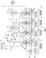
- FIG. 1is a block diagram illustrating a plurality of CATV entry adapters 10 according to the invention, shown interconnecting CATV network 20 and a plurality of IHE networks 14 , each located at subscriber premises 12 .
- FIG. 2is a generalized perspective view of one embodiment of CATV entry adapter 10 of FIG. 1 , connected to IHE network 14 in one subscriber premises 12 , with more details of IHE network 14 and active and passive subscriber equipment 16 connected to CATV entry adapter 10 shown in block diagram form, and also showing components forming nodes of IHE network 14 .
- FIG. 3is a block diagram of functional components of one embodiment of CATV entry adapter 10 shown in FIG. 2 , shown connected to CATV network 20 .
- FIG. 4is a block diagram similar to FIG. 3 , illustrating the connection of additional IHE nodes 74 of IHE network 14 to passive port 45 of CATV entry adapter 10 .
- FIG. 6is a block diagram illustrating a further embodiment of a plurality of CATV entry adapters 10 according to the invention, shown interconnecting CATV network 20 and a plurality of In-Home Entertainment networks 14 each located at one of a plurality of subscriber premises 12 .
- FIG. 7is a generalized perspective view of another embodiment of CATV entry adapter 10 according to the invention, connected to IHE network 14 in one subscriber premises 12 , with more details of IHE network 14 and active and passive subscriber equipment 16 and 21 connected to CATV entry adapter 10 shown in block diagram form, and also showing components forming nodes 74 of IHE network 14 .
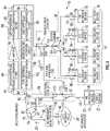
- FIG. 8is a block diagram of functional components of an embodiment of CATV entry adapter 10 shown in FIG. 7 , shown connected to CATV network 20 .
- Each CATV entry adapter 10is located at a subscriber premises 12 and forms a part of an In-Home Entertainment (IHE) network 14 .
- Multimedia devices 16are connected to each IHE network 14 in each subscriber premises 12 .
- Each multimedia device 16communicates multimedia content, or IHE signals, between itself and other IHE multimedia devices using IHE network 14 , which is formed in part by the preexisting coaxial cable infrastructure (represented generally by coaxial cables 18 ) present in subscriber premises 12 .
- Examples of multimedia devices 16are digital video recorders, computers, data modems, computer game playing devices, television sets, television set-top boxes, and other audio and visual entertainment devices. Often, but not by way of limitation, the multimedia devices 16 constitute active subscriber equipment.
- CATV entry adapter 10is also a part of conventional CATV network 20 .
- Each CATV entry adapter 10delivers CATV content or signals from CATV network 20 to subscriber equipment at the subscriber premises 12 .
- the subscriber equipmentincludes the multimedia devices 16 , but may also include other devices which do not operate as a part of the IHE network 14 but which are intended to function as a result of connection to CATV network 20 .
- Examples of subscriber equipment which are normally not part of the IHE network 14are voice modems 46 and connected telephone sets 48 .
- subscriber equipmentincludes any equipment located at a subscriber premises 12 that is coupled to the passive or active entry ports of entry adapter 10 .
- CATV entry adapter 10has beneficial characteristics which allow it to function in multiple roles simultaneously in both IHE network 14 and in CATV network 20 , thereby benefiting both the IHE network 14 and the CATV network 20 .
- CATV entry adapter 10functions as a hub in IHE network 14 , to effectively transfer IHE signals between multimedia devices 16 , including those that might be connected to passive ports of the CATV entry adapter 10 , as will be described in greater detail below.
- CATV entry adapter 10also functions in a conventional role as an interface between CATV network 20 and the subscriber equipment located at the subscriber premises 12 , thereby facilitating CATV service to the subscriber.
- CATV network 20 shown in FIG. 1has a typical topology.
- Downstream signals 22originate from programming sources at headend 24 of CATV network 20 , and are conducted to CATV entry adapter 10 in a sequential path through main trunk cable 26 , signal splitter/combiner 28 , secondary trunk cables 30 , another signal splitter/combiner 32 , distribution cable branches 34 , cable taps 36 , and drop cables 38 .
- Upstream signals 40are delivered from CATV entry adapter 10 to CATV network 20 , and are conducted to headend 24 in a reverse sequential path.
- Interspersed at appropriate locations within the topology of CATV network 20are conventional repeater amplifiers 42 , which amplify both the downstream signals 22 and the upstream signals 40 .
- Conventional repeater amplifiersmay also be included in cable taps 36 . Cable taps 36 and signal splitter/combiners 28 and 32 divide a single downstream signal 22 into multiple separate downstream signals, and combine multiple upstream signals 40 into a single upstream signal.
- FIG. 3are divided into multiple copies and delivered from a plurality of active ports (collectively referenced at 49 in FIG. 1 , but individually referenced at 50 , 52 , 54 and 56 in FIG. 2 and FIG. 3 ) to subscriber equipment located at subscriber premises 12 .
- CATV subscriber equipmenttypically generates CATV upstream signals and delivers them to CATV entry adapter 10 for delivery to CATV network 20 .
- the CATV upstream signals 40may be passive CATV upstream signals 82 (see FIG. 3 ) generated by passive subscriber equipment, exemplified by voice modem 46 and the telephone set 48 , or the CATV upstream signals 40 may be active CATV upstream signals 96 (See FIG. 3 ) generated by active subscriber equipment exemplified by set-top boxes connected to television sets (neither shown). Set top boxes allow the subscriber/viewer to make programming and viewing selections.
- CATV entry adapter 10is located at each subscriber premises 12 .
- the number of active and passive ports 45 , 50 , 52 , 54 and 56is dictated by the number of coaxial cables 18 which are muted throughout the subscriber premises. Passive and active ports 45 , 50 , 52 , 54 are used to each connect to at least one of the plurality of pieces of subscriber equipment at subscriber premises 12 .
- the CATV entry adapter 10 shown in FIG. 2includes seven ports, other entry adapters 10 according to the invention have a larger or smaller number of ports.
- the number and routing of the coaxial cables 18 within subscriber premises 12constitute the in-home or subscriber premise cable infrastructure that is used by IHE network 14 ( FIG. 1 ).
- CATV service providersupplies CATV entry adapter 10 for use by each subscriber, it is advantageous to reduce the number of different configurations of CATV entry adapters. Doing so offers economies of scale in mass production, reduces the opportunity for errors in installation, allows the subscriber to expand and change the in-home cable infrastructure, and reduces inventory costs, among other things.
- CATV entry adapter 10also functions as a hub in IHE network 14 ( FIG. 1 ). With built-in hub capability as described below, and with the capability to use all of the available ports for connection to multimedia devices 16 . CATV entry adapter 10 is more useful and economical to both the CATV service provider and the subscriber who wishes to implement an IHE network at his or her premises.
- Each of coaxial cables 18 of the in-home cable infrastructureterminates at a cable outlet 70 .
- Those coaxial cables 18 which are not currently in useare terminated with an appropriate termination resistor (not shown) located at cable outlet 70 of these coaxial cables 18 .
- Cable outlet 70 of coaxial cables 18 being used by the subscriberare connected to either an IHE interface device 72 where a multimedia device 16 is connected, to a multimedia device 16 which is IHE-enabled, or to some other form of subscriber equipment.
- Each IHE interface device 72contains a controller which is programmed with the necessary functionality to implement the IHE communication protocol. Each IHE interface device 72 is connected between the cable outlet 70 and a multimedia device 16 . When the multimedia device 16 creates output signals, those output signals are encapsulated or otherwise embodied in IHE signals 105 created by the IHE interface device 72 , and then IHE signals 105 are communicated by one IHE interface device 72 through coaxial cables 18 of the in-home cable infrastructure, through CATV entry adapter 10 , and to another IHE interface device 72 . The other IHE-enabled device 16 or IHE interface device 72 that is receiving IHE signals 105 extracts the original output signals that were encapsulated or otherwise embodied in IHE signals 105 .
- IHE interface device 72supplies those original output signals to the multimedia device 16 to which the IHE interface device 72 is attached. In this manner, IHE signals or multimedia content 105 from one multimedia device 16 are/is communicated through IHE network 14 to another multimedia device 16 for use at its location. Functioning in this manner, and in terms of the conventional terminology used in the field of networks, the IHE interface device 72 and the multimedia device 16 form one node 74 of the IHE network 14 . IE signals 105 are therefore communicated between the different IHE nodes 74 of the IHE network 14 .
- CATV entry adapter 10The internal functional components of one embodiment of CATV entry adapter 10 are shown in FIG. 3 .
- Those internal circuit componentsinclude conventional bi-directional signal splitter/combiner 76 which separates downstream signals 22 from CATV network 20 at entry pot 44 into passive CATV downstream signals 78 and active CATV downstream signals 80 .
- Bidirectional splitters/combiners as described in this documentinclude an input or common terminal, and two output or signal component leg terminals. Signals received at the input or common terminal of a bidirectional splitter/combiner are divided into two signals, with one each presented to each of the output or signal component leg terminals. Signals received at the output or signal component legs of the bidirectional splitter/combiner are combined into a single signal and presented to the input or common terminal.
- Bidirectional splitter/combiner 76includes input or common terminal 75 , first signal component leg or output terminal 81 , and second signal component leg or output terminal 77 . Bidirectional splitter/combiner 76 in this embodiment conducts CATV downstream signals in the CATV downstream signal frequency range. CATV upstream signals in the CATV upstream signal frequency range, and IHE signals in the IHE signal frequency range between the common terminal and the first and second signal component legs.
- Passive CATV downstream signals 78are conducted directly to and through passive port 45 to passive subscriber equipment 46 and 48 .
- Passive CATV upstream signals 82are created by passive subscriber equipment 46 and 48 and are conducted through passive port 45 directly through CATV passive signal communication path 77 to signal splitter/combiner 76 to become upstream signals 40 in CATV network 20 .
- the direct CATV passive signal communication path 79 for passive signals 82 in CATV entry adapter 10contains no active electronic components that might fail or malfunction, thereby enhancing the reliability of CATV passive communications.
- CATV passive signal communication path 79is intended to be as reliable as possible since it may be used in emergency and critical circumstances.
- Active CATV downstream signals 80are conducted to first CATV downstream frequency bandpass filter 84 in CATV active downstream signal communication path 85 .
- Downstream filter 84passes signals having frequencies in the CATV downstream signal frequency range of 54-1002 MHz. and rejects signals having frequencies in other ranges.
- the CATV downstream signals passed by the filter 84are amplified by amplifier 86 and then supplied to second CATV downstream signal frequency bandpass filter 88 , both of which are also part of CATV active downstream signal communication path 85 .
- the amplified and further filtered CATV downstream signals 80are then conducted to bidirectional splitter/combiner 90 , which splits or divides those signals into two identical CATV downstream signals 80 .
- the two signals 80 from bidirectional splitter/combiner 90are supplied as inputs to two other bidirectional splitters/combiners 92 and 94 , respectively, which are connected in cascade with bidirectional splitter/combiner 90 .
- Splitters/combiners 92 and 94again split or divide each of their two input signals into two identical CATV downstream signals 80 .
- the four output signals from the cascade-connected splitters/combiners 90 , 92 and 94are applied at the active ports 50 , 52 , 54 and 56 of CATV entry adapter 10 .
- those signals 96are likewise passed through IHE interface device 72 without change or influence and are then conducted through cable outlet 70 , coaxial cable 18 and active ports 50 , 52 , 54 or 56 to splitters/combiners 92 and 94 .
- the splitters/combiners 92 and 94combine all CATV upstream signals 96 and supply those upstream signals 96 to splitter 90 .
- Splitter 90combines the CATV upstream signals 96 from splitters 92 and 94 and supplies them to first CATV upstream frequency bandpass filter 98 , which forms a part of CATV active upstream signal communication path 99 .
- Filter 98passes signals having frequencies in the CATV upstream signal frequency range of 5-42 MHz.
- CATV upstream signals 96 passed by filter 84are then preferably supplied to an ingress noise mitigation circuit 100 .
- Ingress noise mitigation circuit 100suppresses ingress noise in the range of 0-5 MHz that may have originated from noise sources within the subscriber premises.
- Ingress noise mitigation circuit 100is optional in in the CATV entry adapter 10 , but if employed, is preferably employed in the form described in U.S. patent application Ser. No. 12/250,227, filed Oct. 13, 2008, and titled Ingress Noise Inhibiting Network Interface Device and Method for Cable Television Networks, which is assigned to the assignee hereof.
- CATV upstream signals 96 leaving circuit 100are applied to second CATV upstream frequency bandpass filter 102 .
- Ingress noise mitigation circuit 100 and second CATV upstream bandpass filter 102are part of CATV active upstream signal communication path 99 .
- the filtered active upstream signals 96 leaving second filter 102are supplied to first signal component leg 81 of bidirectional splitter/combiner 76 , and are conducted through CATV entry port 44 to CATV network 20 .
- IHE network 14exists only between and through the active ports 50 , 52 , 54 and 56 , as is shown in FIG. 3 .
- IHE signals 105 from IHE interface devices 72are communicated through cable outlets 70 , coaxial cables 18 , active ports 50 , 52 , 54 and 56 , and splitters/combiners 92 , 94 and 90 .
- IHE signals 105traverse or jump between the outputs of the splitters/combiners.
- splitters/combiners 90 , 92 and 94connect all of the coaxial cables 18 at a common location so that all the IHE signals 105 may be conducted between all of the IHE interface devices 72 .
- splitter/combiner 104Whenever there is no life-line voice service connected to passive port 45 of CATV entry adapter 10 , passive port 45 becomes available for use as part of IHE network 14 , as is shown in FIG. 4 .
- splitter/combiner 104has been connected externally to passive port 45 of CATV entry adapter 10 . Consequently, splitter/combiner 104 is not built-in or incorporated within CATV entry adapter 10 , but instead, splitter/combiner 104 is part of the in-home cable infrastructure.
- Coaxial cables 18connect to splitter/combiner 104 and cable outlets 70 of those those coaxial cables connect to IHE interface devices 72 which are connected to multimedia devices 16 in the manner previously described.
- IHE signals 105 generated by the two IHE interface devices 72are also conducted to splitter/combiner 76 where those signals will jump or traverse the legs of splitter/combiner 76 .
- IHE frequency bandpass filter 106passes IHE signals in the 1125-1675 MHz frequency range without significant attenuation. Consequently. IHE signals 105 pass freely through filter 106 without substantial attenuation, where IHE signals 105 jump or traverse splitter/combiner 76 in substantially the same way that IHE signals jump or traverse splitters 90 , 92 , 94 and 104 .
- IHE signals 105traverse signal bidirectional splitter/combiner 76 between first signal component leg 81 and second signal component leg 77 .
- IHE signals 105traverse signal bidirectional splitter/combiner 76 between first signal component leg 81 and second signal component leg 77 to enable conduction of IHE signals 105 between IHE signal communication path 107 and CATV passive signal communication path 79 .
- CATV passive signal communication path 79conducts CATV downstream signals in the CATV downstream signal frequency range and CATV upstream signals in the CATV upstream signal frequency range between second signal component leg 77 and passive port 45 .
- all of the subscriber equipment multimedia devices 16may communicate with each other through CATV entry adapter 10 without significant attenuation created by the active circuit components in the CATV upstream and downstream signal communication paths 85 and 99 .
- including bidirectional IHE frequency bandpass filter 106 in the CATV entry adapter 10has no adverse influence over its functionality in distributing CATV signals, because IHE frequency bandpass filter 106 rejects CATV active downstream and upstream signals 80 and 96 conducted through CATV active signal communication paths 85 and 99 .
- Bidirectional IHE frequency bandpass filter 106can also be connected to the input side of the splitter combiner 76 , as shown in FIG. 5 .
- CATV entry adapter 10includes IHE frequency rejection filter 108 connected between splitter/combiner 76 and CATV network entry port 44 .
- IHE frequency rejection filter 108is directly connected between signal bidirectional splitter/combiner 76 and CATV entry port 44 .
- IHE frequency rejection filter 108is formed internal to housing 58 . IHE frequency rejection filter 108 prevents signals in the HE frequency range from passing from splitter/combiner 76 into CATV network 20 , but allows CATV downstream and CATV upstream signals to pass without impairment.
- IHE frequency rejection filter 108absorbs the energy of any IHE signals, thereby preventing IHE signals 105 from reaching CATV network 20 . Eliminating IHE signals by use of IHE frequency rejection filter 108 prevents IHE signals from IHE network 14 from being received and comprehended at an adjacent subscriber premises. Without IHE frequency rejection filter 108 and as understood from FIG. 1 . IHE signals from one CATV entry adapter 10 could traverse the drop cables 38 to the cable tap 36 , and from the cable tap through another drop cable 38 of that cable tap 36 to an adjacent CATV entry adapter 10 . IHE frequency rejection filter 108 prevents this from happening.
- IHE frequency rejection filter 108In addition to protecting the security and privacy of IHE signals within IHE network 14 in each subscriber premises 12 , IHE frequency rejection filter 108 also prevents IHE signals from one subscriber premise from adversely influencing or deteriorating the quality of IHE signals in an adjacent IHE network connected to a cable tap 36 ( FIG. 1 ).
- CATV entry adapter 10beneficially contributes to establishing an in-home entertainment (IHE) network. All of the active and passive ports of the CATV entry adapter are usable in the IHE network.
- CATV entry adapter 10is therefore fully functional as an IHE network hub to communicate all IHE signals 105 between all IHE interface devices without substantially attenuating the strength of the IHE signals in such a way that the IHE interface devices are unable to compensate in the manner intended by the IHE communication protocol.
- CATV entry adapter 10prevents or greatly inhibits IHE signals from reaching CATV network 20 . Doing so does not compromise the privacy and security of IHE content which is expected to be maintained only within the IHE network of the subscriber premises.
- CATV entry adapter 10By confining the IHE signals to the 11iE network at the subscriber premises, IHE signals are not available over the CATV network to interfere with other IHE networks established at other subscriber premises.
- the advantageous functionality of CATV entry adapter 10 in regard to IHE network communicationsis protected within the housing of the CATV entry adapter, to shield it from unauthorized removal, tampering, forgetfulness in original installation, and physical exposure.
- CATV entry adapter 10does not inhibit or otherwise adversely influence normal CATV signal distribution functionality.
- the multi-functional aspects of CATV entry adapter 10allow it to be used in a wide variety of situations, thereby increasing its economies of scale and facilitating greater convenience in installation by the CATV service provider.
- use of CATV entry adapter 10allows subscribers more flexibility in expanding and changing both their CATV subscriber equipment and their IHE network and multimedia devices.
- FIG. 6shows a block diagram of a further embodiment of CATV network 20 , subscriber premises 12 and a plurality of CATV entry devices 10 according to the invention, some of which have eMTA device 21 connected to passive port 45 of CATV entry adapter 10 .
- EMTA device 21includes voice modem 46 and telephone set 48 in this embodiment.
- Subscriber equipment 16 and eMTA device 21receive CATV downstream signals from CATV network 20 , and subscriber equipment 16 and eMTA device 21 send CATV upstream signals to CATV network 20 .
- CATV upstream and downstream signals communicated between CATV network 20 and eMTA device 21are passive CATV signals 82 and 78 respectively.
- the CATV upstream and downstream signals sent to and received by CATV network 20 by the other subscriber equipmentare active CATV signals 96 and 80 , respectively.
- An IHE-enabled eMTA device 23also communicates IHE signals 105 using IHE network 14 .
- An IHE-enabled eMTA device 23includes a conventional eMTA device 21 and an IHE interface device 73 .
- the IHE interface device 73permits communication of IHE signals among all IHE-enabled multimedia devices 16 .
- CATV entry adapter 10functions as a hub in IHE network 14 , to effectively transfer or distribute IHE signals between multimedia devices 16 and eMTA interface device 73 .
- CATV entry adapter 10 in this embodimenteffectively communicates IHE signals 105 between the IHE-enabled eMTA device 23 —a first one of the plurality of pieces of subscriber equipment coupled to entry adapter 10 - and multimedia devices 16 coupled to the active ports—one of which is a second one of the plurality of pieces of subscriber equipment coupled to entry adapter 10 —thereby distributing the functionality of the eMTA device 23 to the multimedia devices 16 throughout the subscriber premises.
- CATV entry adapter 10also functions in a conventional role as an interface between CATV network 20 and subscriber equipment 16 and 23 located at subscriber premises 12 , communicating CATV signals between subscriber equipment 16 and CATV network 20 . These and other improvements and functions are described in greater detail below.
- CATV entry adapter 10receives CATV downstream signals 22 from the CATV network 20 at CATV network connection or entry port 44 as described above. Passive CATV downstream signals 78 are conducted through CATV entry adapter 10 to eMTA device 21 without amplification, enhancement, modification or other substantial conditioning ( FIG. 3 ). Passive CATV downstream signals 78 are delivered from passive port 45 to passive subscriber equipment, i.e. eMTA device 23 represented by the voice modem 46 connected to telephone set 48 through HE-enabled eMTA device 21 .
- CATV subscriber equipment 16generates upstream signals 40 and delivers them to the CATV entry adapter 10 for delivery to the CATV network 20 as described above.
- CATV entry adapter 10includes a housing 58 which encloses internal electronic circuit components (shown in one embodiment in FIG. 8 ).
- a mounting flange 60surrounds the housing 58 and holes 62 in the flange 60 allow attachment of the CATV entry adapter 10 to a support structure at the subscriber premises, as described earlier.
- CATV network 20is connected to the CATV network connection entry port 44 of CATV entry adapter 10 .
- the ports 44 , 45 , 50 , 52 , 54 , 56 and 68are each preferably formed by a conventional female coaxial cable connector which is mechanically connected the housing 58 and which is electrically connected to internal components of CATV entry adapter 10 .
- Coaxial cables 18 from subscriber premises 12 cable infrastructure and drop cables 38( FIG. 1 and FIG. 6 ) are connected to CATV entry adapter 10 by mechanically connecting the corresponding mating male coaxial cable connectors (not shown) on these coaxial cables to the female coaxial cable connectors forming the ports 44 , 45 , 50 , 52 , 54 , 56 and 68 .
- CATV entry adapter 10is located at each subscriber premises.
- the number of active and passive ports 45 , 50 , 52 , 54 and 56is dictated by the number of coaxial cables 18 which are routed throughout the subscriber premises.
- CATV entry adapter 10 shown in FIG. 7 and FIG. 8includes seven ports, other entry adapters may have a larger or smaller number of ports.
- the number and routing of the coaxial cables 18 within the subscriber premisesconstitute the in-home or subscriber premise cable infrastructure that is used by the IHE network 14 ( FIG. 6 ).
- CATV entry adapter 10in the embodiment shown in FIG. 6 through FIG. 8 permits the effective use of subscriber equipment that includes both eMTA devices 23 and multimedia devices 16 connected in IHE network 14 , without degrading or compromising the VOIP service supplied to IHE-enabled eMTA device 23 .
- IHE interface devices 72are shown as separate from multimedia devices 16 , in some embodiments an IHE interface device 72 is incorporated within or is an integral part of an IHE-IHE-enabled multimedia device 16 . However, for those multimedia devices 16 which do not include a built-in IHE interface device 72 , a separate IHE-enabled device 72 is connected to the multimedia device 16 to thereby allow it to participate as a node in IHE network 14 .
- EMTA device 21participates in IE network 14 due to the connection of eMTA device 21 to IHE interface device 73 .
- the combination of eMTA device 21 and the connected IHE interface device 73constitutes IHE-enabled eMTA device 23 .
- IHE interface device 73may be an integral part of eMTA device 23 .
- IHE interface device 73is similar to the IHE interface devices 72 in communicating IHE signals, but IHE interface device 73 has the additional functional capability of communicating passive CATV signals to and from eMTA device 23 when no electrical power is available to IHE interface device 73 .
- FIG. 8The internal functional components of CATV entry adapter 10 according to the invention of FIG. 6 through FIG. 8 are shown in FIG. 8 .
- Those internal circuit componentsinclude first conventional bi-directional signal splitter/combiner 76 which splits downstream signals 22 from CATV network 20 received at common terminal 75 from entry port 44 .
- Downstream signals 22are split into passive CATV downstream signals 78 at second signal component leg 77 and into active CATV downstream signals 80 at first signal component leg 81 .
- Passive CATV downstream signals 78are conducted in CATV passive signal communication path 79 to and through passive port 45 , through IHE interface device 73 and to eMTA device 21 .
- Passive CATV upstream signals 82are created by eMTA device 21 and are conducted through IHE interface device 73 , passive port 45 and CATV passive signal communication path 79 to second signal component leg 77 of signal splitter/combiner 76 to become CATV upstream signals 40 in CATV network 20 .
- CATV passive signal communication path 79 for the passive CATV signals in CATV entry adapter 10contains no power-consuming active electronic components that might fail or malfunction, thereby enhancing the reliability of CATV passive communications.
- CATV passive signal communication path 79is intended to be as reliable as possible since it is used in emergency and critical circumstances.
- Active CATV downstream signals 80 from first signal component leg 81 of splitter/combiner 76are conducted to first CATV downstream frequency bandpass filter 84 in CATV active downstream signal communication path 85 .
- Downstream filter 84passes signals having frequencies in the CATV downstream frequency range of 54-1002 MHz, and rejects signals having frequencies in other ranges.
- Downstream signals 80 passed by filter 84are amplified by amplifier 86 and then supplied to second CATV downstream frequency bandpass filter 88 , both of which are also part of CATV active downstream signal communication path 85 .
- the amplified and further filtered active CATV downstream signals 80are conducted through active-side directional coupler 89 which forms part of combined signal communication path 90 .
- CATV downstream signals 80are conducted through active-side directional coupler 89 to a common terminal of second conventional bidirectional splitter/combiner 94 which also forms part of combined signal communication path 90 .
- Second splitter/combiner 94splits or divides active CATV downstream signals 80 into four identical CATV downstream signals, each of which has approximately one-fourth of the power or signal strength of CATV downstream signal 80 initially applied to the splitter/combiner 94 .
- Each of the split signalsis delivered from one of four separate signal component legs 91 , 92 , 93 and 95 of splitter/combiner 94 .
- the four split signals from signal component legs 91 , 92 , 93 and 95 of the splitter/combiner 94are applied at active ports 50 , 52 , 54 and 56 of CATV entry adapter 10 , respectively.
- active ports 50 , 52 , 54 and 56are shown, more active ports are achieved by use of a splitter/combiner with a different number of signal component legs, or by use of multiple cascaded splitters/combiners, to derive the desired number of split signals to be applied to all of the active ports of CATV entry adapter 10 .
- each IHE interface device 72passes those downstream signals directly to connected multimedia device 16 .
- the IHE interface device 72does not modify or otherwise influence CATV downstream signals 80 passing through it.
- those CATV upstream signals 96are likewise passed through the IHE interface device 72 without change or influence and are then conducted through cable outlet 70 , coaxial cable 18 and active ports 50 , 52 , 54 or 56 to splitter/combiner 94 .
- Splitter/combiner 94combines all CATV upstream signals 96 and supplies those signals as combined active upstream signals 96 to active-side directional coupler 89 .
- CATV upstream signals 96 from active-side directional coupler 89are supplied to first CATV upstream frequency bandpass filter 98 , which forms a part of CATV active upstream signal communication path 99 .
- Filter 98passes signals having frequencies in the CATV upstream frequency range of 5-42 MHz, and rejects signals having frequencies in other ranges.
- CATV upstream signals 96 passed by filter 98are then supplied to ingress noise mitigation circuit 100 .
- Ingress noise mitigation circuit 100suppresses ingress noise in the range of 0-42 MHz that may have originated from noise sources within subscriber premises 12 .
- Use of ingress noise mitigation circuit 100is optional in CATV entry adapter 10 , but if employed, noise mitigation circuit 100 is preferably employed in the form described in US patent application Ser. No. 12/250,227, filed Oct. 13, 2008, and titled Ingress Noise Inhibiting Network Interface Device and Method for Cable Television Networks, which is assigned to the assignee hereof.
- CATV upstream signals 96 leaving ingress noise mitigation circuit 100are then applied to second CATV upstream frequency bandpass filter 102 .
- Second CATV upstream frequency bandpass filter 102is also optional for use. Second upstream bandpass filter 102 may not be necessary if first upstream bandpass filter 98 provides sufficient frequency filtering characteristics and ingress noise mitigation circuit 100 is not used. Second upstream bandpass filter 102 may also be eliminated under certain circumstances, even when ingress noise mitigation circuit 100 is used. Ingress noise mitigation circuit 100 and second CATV upstream bandpass filter 102 are part of CATV active upstream signal communication path 99 .
- Active CATV upstream signals 96 from CATV active upstream signal communication path 99are supplied to first signal component leg 81 of first splitter/combiner 76 .
- Passive CATV upstream signals 82 from CATV passive signal communication path 79are supplied to second signal component leg 77 of first splitter/combiner 76 .
- Splitter/combiner 76combines the signals supplied to its signal component legs 77 and 81 to form a single combined upstream signal 40 which is supplied through entry port 44 to CATV network 20 .
- IHE network 14exists only between and through active ports 50 , 52 , 54 and 56 .
- IHE signals 105 from IHE interface devices 72are communicated through the cable outlets 70 , the coaxial cables 18 , the active ports 50 , 52 , 54 and 56 , and the splitter 94 .
- Splitter 94has a conventional construction with relatively low isolation between all of its signal component legs 91 , 92 , 93 and 95 in the HE signal frequency range to facilitate IHE signal communication between its signal component legs of 91 , 92 , 93 and 95 . In this manner, splitter 94 conducts IHE signals 105 to all of the coaxial cables 18 connected to entry adapter 10 to achieve IHE signal communication among all of the IHE interface devices 72 .
- Attaching non-IHE-enabled eMTA subscriber equipment to the passive port 45deprives the subscriber of the benefits of using passive port 45 as part of IHE network 14 .
- Connecting IHE-enabled subscriber equipment, such as IHE-enabled eMTA device 23 , to passive port 45allows IHE-enabled eMTA device 23 to participate in IHE network 14 .
- the subscriberobtains the capability to distribute the telephony and other services to other multimedia devices 16 in IHE network 14 .
- Exemplary multimedia devices 16which may receive the distributed telephone service include auxiliary telephones and answering machines, among other devices.
- IHE network 14includes passive port 45 and active ports 50 , 52 , 54 and 56 .
- IHE signals 105are not conducted through CATV active upstream and downstream signal communication paths 99 and 85 because filters 84 , 88 , 98 and 102 severely attenuate IHE signals in the 1125-1675 MHZ frequency range.
- filters 84 , 88 , 98 and 102severely attenuate IHE signals in the 1125-1675 MHZ frequency range.
- attempting to conduct IHE signals in the reverse direction through amplifier 86results in severe attenuation of those signals, if such conduction is even possible.
- a similar resultapplies when attempting to conduct IHE signals through ingress noise mitigation circuit 100 .
- IHE signal bypass path 106is established between CATV passive signal communication path 79 and combined signal communication path 90 .
- IHE signal bypass path 106includes active-side directional coupler 89 and passive-side directional coupler 112 .
- IHE signal bypass path 106extends between coupled port 108 of active-side directional coupler 89 and coupled port 110 of passive-side directional coupler 112 .
- passive-side directional coupler 112is part of CATV passive signal communication path 79
- active-side directional coupler 89is part of combined signal communication path 90
- IHE signal bypass path 106connects to CATV active signal communication paths 85 and 99 .
- Directional couplers 89 and 112are of conventional construction, and each has four ports; coupled ports 108 and 110 ; input ports 116 and 117 , through ports 118 and 119 , and isolated ports 121 and 123 , respectively. Isolated ports 121 and 123 are terminated in their appropriate characteristic impedance (not shown) in entry adapter 10 .
- the conventional functionality of each coupler 89 and 112causes the majority of power incident at input ports 116 and 117 to flow through the directional couplers to through ports 118 and 119 , with a residual amount of the input power flowing to coupled ports 108 and 110 . Substantially none of the power incident at input ports 116 and 117 is coupled to isolated ports 121 and 123 .
- IHE signals 105 from IHE interface devices 72 and 73are readily conducted through coupled ports 108 and 110 and through IHE signal bypass path 106 , thereby assuring relatively strong IHE signal communication between the IHE-enabled devices connected to ports 45 and 70 .
- each coupler 89 and 112causes the majority of power incident at through ports 118 and 119 to flow to input ports 116 and 117 . Substantially none of the power incident at through ports 118 and 119 is coupled to coupled ports 108 and 110 .
- the amount of the incident power applied at input ports 116 and 117 which flows to coupled ports 108 and 110is established by the coupling factor associated with each directional coupler.
- the extent of the power rejected at the isolated portsis established by a rejection factor associated with each directional coupler.
- the coupling and rejection factorsalso apply respectively to the coupling and isolation of incident power at through ports 118 and 119 with respect to isolated ports 121 and 123 and coupled ports 108 and 110 .
- Signal paths through directional couplers 89 and 112 from input ports 116 and 117 to through ports 118 and 119 , respectively,are referred to herein as “main legs.” Signals passing in either direction through the main legs incur a small amount of signal attenuation, preferably less than one or two decibels (dB), as described above. Signal paths through directional couplers 89 and 112 from input ports 116 and 117 to coupled ports 108 and 110 are referred to herein as “directional legs.” Signals passing in either direction through the directional legs incur a modest amount of signal attenuation of around 10 to 20 dB, as described above. Signals are substantially prevented from passing between through ports 118 and 119 and coupled ports 108 and 110 , respectively, due to the normal functionality of directional couplers 89 and 112 , as described above.
- Input ports 116 and 117 of directional couplers 89 and 112are connected to the common terminal of splitter 94 and passive port 45 , respectively.
- Through port 118 of directional coupler 89is operatively connected to first signal component leg 81 of splitter/combiner 76 through CATV active downstream and upstream signal communication paths 85 and 99 .
- Through port 119 of directional coupler 112is operatively connected to second signal component leg 77 of splitter/combiner 76 .
- the small amount of signal attenuation which the CATV signals incur passing through the main legs of directional couplers 89 and 112does not impact the functionality of IHE-enabled eMTA device 23 or the other subscriber equipment which may be connected to the active ports of CATV entry adapter 10 .
- IHE signals 105which originate from IHE interface device 73 are communicated to IHE interface devices 72 by passing through IHE signal bypass path 106 . i.e. through passive port 45 , input port 117 of passive-side directional coupler 112 , the directional leg and coupled port 110 of passive-side directional coupler 112 , IHE signal bypass path 106 , coupled port 108 and directional leg of active-side directional coupler 89 , and input port 116 of active-side directional coupler 112 .
- the signalsare then conducted through splitter 94 , and active ports 50 , 52 , 54 and 56 to IHE interface devices 72 .
- IHE signals 105which originate from the HE interface devices 72 are communicated to IHE interface device 73 . These HE signals 105 pass through splitter 94 , input port 116 of active-side directional coupler 89 , coupled port 108 and the directional leg of active-side directional coupler 89 , IHE signal bypass path 106 , coupled port 110 and the directional leg of passive-side directional coupler 112 , and input port 117 of passive-side directional coupler 112 , to passive port 45 . In this manner. IHE-enabled eMTA device 23 communicates with IHE interface devices 72 and multimedia devices 16 within IHE network 14 .
- CATV upstream signals 82 and 96 as well as IHE signals 105are conducted through IHE signal bypass path 106 . However, any CATV upstream signals which are communicated through IHE signal bypass path 106 are ignored by IHE-enabled eMTA device 23 and/or IHE interface devices 72 and 73 which receive them.
- IHE signal bypass path 106does not contain a frequency filter, the problems of tuning a third frequency filter in parallel with the two active downstream and upstream signal communication paths 85 and 99 is avoided. Using only two parallel frequency specific signal communication paths 85 and 99 greatly simplifies the tuning of the bandpass filters in those signal communication paths compared to the complexity of tuning filters in three parallel frequency-specific signal communication paths.
- the directional couplers 89 and 112do not require power to operate, thereby allowing IHE-enabled eMTA device 23 to communicate with CATV network 20 in situations where power to CATV entry adapter 10 is interrupted.
- Directional couplers 89 and 112are readily available components which simplify the manufacturing of CATV entry adapter 10 .
- IHE signal bypass path 106 and directional couplers 89 and 112effectively extend IHE network 14 to include IHE compatible devices connected to passive port 45 , in addition to those connected to active ports 50 , 52 , 54 and 56 .
- passive port 45within IHE network 14 enables an IHE compatible device connected to passive port 45 , such as IHE-enabled eMTA device 23 , to communicate with multimedia devices 16 within IHE network 14 .
- Multimedia devices 16which may beneficially communicate with IHE-enabled eMTA device 23 include auxiliary phones and automated answering machines, among other multimedia devices.
- CATV entry adapter 10also includes an IHE frequency rejection filter 108 connected between splitter/combiner 76 and CATV network entry port 44 .
- IHE frequency rejection filter 108prevents IHE signals from passing from entry adapter 10 into CATV network 20 , but allows upstream and downstream CATV signals to pass without significant impairment.
- IHE frequency rejection filter 108absorbs the energy of IHE signals, thereby preventing IHE signals from reaching CATV network 20 .
- IHE frequency rejection filter 108also prevents the IHE signals from IHE network 14 ( FIG. 1 and FIG. 6 ) from being received at an adjacent subscriber premises 12 , as discussed earlier.
- CATV entry adapter 10beneficially contributes to the quality of service available from CATV network 20 and from IHE network 14 .
- CATV entry adapter 10is fully functional as an IHE network hub to communicate adequate strength IHE signals between all IHE interface devices and multimedia devices, while simultaneously preserving the intended CATV functionality.
- IHE frequency rejection filter 108avoids compromising the privacy and security of the IHE content which is expected to be maintained only within the IHE network of each subscriber's premises.
- the advantageous functionality of the CATV entry adapteris obtained within the housing of the CATV entry adapter, thereby shielding that desirable functionality from unauthorized tampering, negligence in installation, and physical exposure.
- the multi-functional aspects of the CATV entry adapterallow it to be used in many situations, thereby increasing its economies of scale and use and facilitating greater convenience in installation by the CATV service provider.
- the CATV entry adapter 10allows subscribers more flexibility in expanding and changing both their CATV subscriber equipment and their HE network and multimedia devices.
Landscapes
- Engineering & Computer Science (AREA)
- Signal Processing (AREA)
- Multimedia (AREA)
- Computer Networks & Wireless Communication (AREA)
- Two-Way Televisions, Distribution Of Moving Picture Or The Like (AREA)
- Small-Scale Networks (AREA)
Abstract
Description
Claims (18)
Priority Applications (2)
| Application Number | Priority Date | Filing Date | Title |
|---|---|---|---|
| US17/159,919US11528526B2 (en) | 2008-10-21 | 2021-01-27 | Entry device for communicating external network signals and in-home network signals |
| US18/080,188US11910052B2 (en) | 2008-10-21 | 2022-12-13 | Entry device for communicating external network signals and in-home network signals |
Applications Claiming Priority (10)
| Application Number | Priority Date | Filing Date | Title |
|---|---|---|---|
| US12/255,008US8286209B2 (en) | 2008-10-21 | 2008-10-21 | Multi-port entry adapter, hub and method for interfacing a CATV network and a MoCA network |
| US12/563,719US8356322B2 (en) | 2009-09-21 | 2009-09-21 | Passive multi-port entry adapter and method for preserving downstream CATV signal strength within in-home network |
| US12/704,833US8429695B2 (en) | 2008-10-21 | 2010-02-12 | CATV entry adapter and method utilizing directional couplers for MoCA signal communication |
| US13/688,420US9167286B2 (en) | 2009-09-21 | 2012-11-29 | Passive multi-port entry adapter and method for preserving downstream CATV signal strength within in-home network |
| US13/863,693US9351051B2 (en) | 2008-10-13 | 2013-04-16 | CATV entry adapter and method for distributing CATV and in-home entertainment signals |
| US15/133,948US9781472B2 (en) | 2008-10-13 | 2016-04-20 | CATV entry adapter and method for distributing CATV and in-home entertainment signals |
| US15/722,302US10154302B2 (en) | 2008-10-13 | 2017-10-02 | CATV entry adapter and method for distributing CATV and in-home entertainment signals |
| US15/880,231US10419813B2 (en) | 2008-10-21 | 2018-01-25 | Passive multi-port entry adapter for preserving downstream CATV signal strength |
| US16/564,949US10917685B2 (en) | 2008-10-21 | 2019-09-09 | Entry device for communicating signals between an external network and an in-home network |
| US17/159,919US11528526B2 (en) | 2008-10-21 | 2021-01-27 | Entry device for communicating external network signals and in-home network signals |
Related Parent Applications (1)
| Application Number | Title | Priority Date | Filing Date |
|---|---|---|---|
| US16/564,949ContinuationUS10917685B2 (en) | 2008-10-21 | 2019-09-09 | Entry device for communicating signals between an external network and an in-home network |
Related Child Applications (1)
| Application Number | Title | Priority Date | Filing Date |
|---|---|---|---|
| US18/080,188ContinuationUS11910052B2 (en) | 2008-10-21 | 2022-12-13 | Entry device for communicating external network signals and in-home network signals |
Publications (2)
| Publication Number | Publication Date |
|---|---|
| US20210219014A1 US20210219014A1 (en) | 2021-07-15 |
| US11528526B2true US11528526B2 (en) | 2022-12-13 |
Family
ID=62190605
Family Applications (12)
| Application Number | Title | Priority Date | Filing Date |
|---|---|---|---|
| US15/722,302ActiveUS10154302B2 (en) | 2008-10-13 | 2017-10-02 | CATV entry adapter and method for distributing CATV and in-home entertainment signals |
| US15/880,231Active2028-12-04US10419813B2 (en) | 2008-10-21 | 2018-01-25 | Passive multi-port entry adapter for preserving downstream CATV signal strength |
| US15/880,166ActiveUS10154303B2 (en) | 2008-10-21 | 2018-01-25 | Entry adapter that blocks different frequency bands and preserves downstream signal strength |
| US15/880,400ActiveUS10284904B2 (en) | 2008-10-21 | 2018-01-25 | Entry adapters for conducting can signals and in-home network signals |
| US15/880,381ActiveUS10284903B2 (en) | 2008-10-21 | 2018-01-25 | Entry adapters for frequency band blocking internal network signals |
| US15/880,363ActiveUS10154304B2 (en) | 2008-10-21 | 2018-01-25 | Methods for controlling CATV signal communication between a CATV network and an in-home network, and preserving downstream CATV signal strength within the in-home network |
| US15/886,800ActiveUS10341718B2 (en) | 2008-10-21 | 2018-02-01 | Passive multi-port entry adapter and method for preserving downstream CATV signal strength within in-home network |
| US15/886,788ActiveUS10149004B2 (en) | 2008-10-21 | 2018-02-01 | Entry device and method for communicating CATV signals and MoCA in-home network signals in an entry device |
| US15/890,573ActiveUS10142677B2 (en) | 2008-10-21 | 2018-02-07 | Entry device for a CATV network |
| US15/891,441ActiveUS10341719B2 (en) | 2008-10-21 | 2018-02-08 | Entry adapter for communicating external signals to an internal network and communicating client signals in the client network |
| US16/564,949ActiveUS10917685B2 (en) | 2008-10-21 | 2019-09-09 | Entry device for communicating signals between an external network and an in-home network |
| US17/159,919ActiveUS11528526B2 (en) | 2008-10-21 | 2021-01-27 | Entry device for communicating external network signals and in-home network signals |
Family Applications Before (11)
| Application Number | Title | Priority Date | Filing Date |
|---|---|---|---|
| US15/722,302ActiveUS10154302B2 (en) | 2008-10-13 | 2017-10-02 | CATV entry adapter and method for distributing CATV and in-home entertainment signals |
| US15/880,231Active2028-12-04US10419813B2 (en) | 2008-10-21 | 2018-01-25 | Passive multi-port entry adapter for preserving downstream CATV signal strength |
| US15/880,166ActiveUS10154303B2 (en) | 2008-10-21 | 2018-01-25 | Entry adapter that blocks different frequency bands and preserves downstream signal strength |
| US15/880,400ActiveUS10284904B2 (en) | 2008-10-21 | 2018-01-25 | Entry adapters for conducting can signals and in-home network signals |
| US15/880,381ActiveUS10284903B2 (en) | 2008-10-21 | 2018-01-25 | Entry adapters for frequency band blocking internal network signals |
| US15/880,363ActiveUS10154304B2 (en) | 2008-10-21 | 2018-01-25 | Methods for controlling CATV signal communication between a CATV network and an in-home network, and preserving downstream CATV signal strength within the in-home network |
| US15/886,800ActiveUS10341718B2 (en) | 2008-10-21 | 2018-02-01 | Passive multi-port entry adapter and method for preserving downstream CATV signal strength within in-home network |
| US15/886,788ActiveUS10149004B2 (en) | 2008-10-21 | 2018-02-01 | Entry device and method for communicating CATV signals and MoCA in-home network signals in an entry device |
| US15/890,573ActiveUS10142677B2 (en) | 2008-10-21 | 2018-02-07 | Entry device for a CATV network |
| US15/891,441ActiveUS10341719B2 (en) | 2008-10-21 | 2018-02-08 | Entry adapter for communicating external signals to an internal network and communicating client signals in the client network |
| US16/564,949ActiveUS10917685B2 (en) | 2008-10-21 | 2019-09-09 | Entry device for communicating signals between an external network and an in-home network |
Country Status (1)
| Country | Link |
|---|---|
| US (12) | US10154302B2 (en) |
Cited By (1)
| Publication number | Priority date | Publication date | Assignee | Title |
|---|---|---|---|---|
| US20230109851A1 (en)* | 2008-10-21 | 2023-04-13 | Ppc Broadband, Inc. | Entry Device for Communicating External Network Signals and In-Home Network Signals |
Families Citing this family (7)
| Publication number | Priority date | Publication date | Assignee | Title |
|---|---|---|---|---|
| US9356796B2 (en) | 2013-04-23 | 2016-05-31 | Times Fiber Communications, Inc. | MoCA gateway splitter |
| US20170142030A1 (en)* | 2015-11-12 | 2017-05-18 | ComplexIQ Inc. | Digital coax network splitter |
| US10425617B2 (en)* | 2016-10-03 | 2019-09-24 | Enseo, Inc. | Distribution element for a self-calibrating RF network and system and method for use of the same |
| WO2019143628A1 (en) | 2018-01-16 | 2019-07-25 | Ppc Broadband, Inc. | Entry adapter for a cable television network |
| US11075472B2 (en)* | 2019-02-05 | 2021-07-27 | Cox Communications, LLC | Systems and methods for active taps in cable networks |
| US11044440B2 (en) | 2019-11-04 | 2021-06-22 | Times Fiber Communications, Inc. | Universal MoCA gateway splitter |
| BR112022025905A2 (en)* | 2020-06-23 | 2023-03-14 | Ppc Broadband Inc | FREQUENCY CONVERTER CABLE NETWORK SIGNAL TRANSMISSION DEVICES |
Citations (205)
| Publication number | Priority date | Publication date | Assignee | Title |
|---|---|---|---|---|
| US2662217A (en) | 1949-03-30 | 1953-12-08 | Rca Corp | Multiple-neck filter |
| US3790909A (en) | 1973-01-26 | 1974-02-05 | Gte Sylvania Inc | Varactor tuner band switch circuitry |
| US3939431A (en) | 1974-11-25 | 1976-02-17 | Motorola, Inc. | Muting circuit for a radio receiver |
| US4027219A (en) | 1974-11-14 | 1977-05-31 | U.S. Philips Corporation | Device for displaying color television images |
| JPS5580989A (en) | 1978-12-15 | 1980-06-18 | Nec Corp | Automatic balancing system for exchange |
| JPS55132126A (en) | 1979-03-31 | 1980-10-14 | Fujitsu Ltd | Selective switching circuit of signal transmission line |
| US4306403A (en) | 1980-10-17 | 1981-12-22 | Deere & Company | Overload sensor for a cotton harvester unit drive |
| JPS5791055A (en) | 1980-11-27 | 1982-06-07 | Toshiba Corp | Branching device |
| US4344499A (en) | 1978-12-08 | 1982-08-17 | C. Van Der Lely N.V. | Tractor with anti-slipping and overloading controls |
| JPS5899913A (en) | 1981-12-10 | 1983-06-14 | 松下電工株式会社 | Chair |
| JPS58101582A (en) | 1981-12-12 | 1983-06-16 | Murata Mfg Co Ltd | Catv system |
| JPS5926709A (en) | 1982-08-04 | 1984-02-13 | Minolta Camera Co Ltd | Control device for driving of lens of automatic focus adjustment type camera |
| US4512033A (en) | 1982-11-29 | 1985-04-16 | C-Cor Labs, Inc. | Remote level adjustment system for use in a multi-terminal communications system |
| US4520508A (en) | 1982-12-21 | 1985-05-28 | General Instrument Corporation | Subscriber terminal for monitoring radio-frequency signal ingress into cable television systems |
| JPS61157035A (en) | 1984-12-28 | 1986-07-16 | Fujitsu Ltd | Impedance matching system |
| US4648123A (en) | 1982-11-29 | 1987-03-03 | C-Cor Labs, Inc. | Remote level measurement system for use in a multi-terminal communications system |
| US4677390A (en) | 1985-05-31 | 1987-06-30 | Texscan Corporation | Low-power feedforward amplifier |
| US4715012A (en) | 1980-10-15 | 1987-12-22 | Massey-Ferguson Services N.V. | Electronic tractor control |
| US4961218A (en) | 1989-05-17 | 1990-10-02 | Tollgrade Communications, Inc. | Enhanced line powered amplifier |
| US4982440A (en) | 1988-04-21 | 1991-01-01 | Videotron Ltee | CATV network with addressable filters receiving MSK upstream signals |
| US5010399A (en) | 1989-07-14 | 1991-04-23 | Inline Connection Corporation | Video transmission and control system utilizing internal telephone lines |
| US5126840A (en) | 1988-04-21 | 1992-06-30 | Videotron Ltee | Filter circuit receiving upstream signals for use in a CATV network |
| US5126686A (en) | 1989-08-15 | 1992-06-30 | Astec International, Ltd. | RF amplifier system having multiple selectable power output levels |
| US5214505A (en) | 1991-04-08 | 1993-05-25 | Hughes Aircraft Company | Automatic rf equalization in passenger aircraft video distribution system |
| US5231660A (en) | 1988-03-10 | 1993-07-27 | Scientific-Atlanta, Inc. | Compensation control for off-premises CATV system |
| JPH05191416A (en) | 1992-01-10 | 1993-07-30 | Matsushita Electric Ind Co Ltd | Automatic termination resistor connector |
| US5245300A (en) | 1991-04-17 | 1993-09-14 | Kokusai Electric Co., Ltd. | Intermediate frequency filter having a ceramic filter |
| US5369642A (en) | 1992-05-29 | 1994-11-29 | Nec Corporation | Switcher for redundant signal transmission system |
| JPH0738580A (en) | 1993-06-28 | 1995-02-07 | Nec Corp | Variable terminating system |
| US5485630A (en) | 1994-03-31 | 1996-01-16 | Panasonic Technologies, Inc. | Audio/video distribution system |
| US5548255A (en) | 1995-06-23 | 1996-08-20 | Microphase Corporation | Compact diplexer connection circuit |
| US5557319A (en) | 1994-12-28 | 1996-09-17 | U.S. Philips Corporation | Subscriber return system for CATV full service networks |
| US5557510A (en) | 1993-11-29 | 1996-09-17 | Gehl Company | Control system for a large round baler |
| US5604528A (en) | 1992-06-10 | 1997-02-18 | Scientific-Atlanta, Inc. | Method and apparatus for providing periodic subscription television services |
| US5719792A (en) | 1995-10-17 | 1998-02-17 | Trilithic, Inc. | Isolator |
| US5740044A (en) | 1995-06-16 | 1998-04-14 | Caterpillar Inc. | Torque limiting power take off control and method of operating same |
| US5745836A (en) | 1995-09-01 | 1998-04-28 | Cable Television Laboratories, Inc. | Undesirable energy suppression system in a contention based communication network |
| US5745838A (en) | 1997-03-14 | 1998-04-28 | Tresness Irrevocable Patent Trust | Return path filter |
| US5815794A (en) | 1995-09-01 | 1998-09-29 | Cable Television Laboratories, Inc. | Undesirable energy suppression system in the return path of a bidirectional cable network having dynamically allocated time slots |
| US5839052A (en) | 1996-02-08 | 1998-11-17 | Qualcom Incorporated | Method and apparatus for integration of a wireless communication system with a cable television system |
| JPH1169334A (en) | 1997-08-19 | 1999-03-09 | Miharu Tsushin Kk | Standby tv modulator for catv head end |
| US5893024A (en) | 1996-08-13 | 1999-04-06 | Motorola, Inc. | Data communication apparatus and method thereof |
| US5937330A (en) | 1997-02-18 | 1999-08-10 | General Instrument Corporation | Settop terminal controlled return path filter for minimizing noise ingress on bidirectional cable systems |
| US5950111A (en) | 1997-09-25 | 1999-09-07 | Lucent Technologies Inc. | Self-terminating coaxial to unshielded twisted-pair cable passive CATV distribution panel |
| US5970053A (en) | 1996-12-24 | 1999-10-19 | Rdl, Inc. | Method and apparatus for controlling peak factor of coherent frequency-division-multiplexed systems |
| US6014547A (en) | 1997-04-28 | 2000-01-11 | General Instrument Corporation | System for enhancing the performance of a CATV settop terminal |
| US6012271A (en) | 1997-01-17 | 2000-01-11 | Welger Gmbh | Round baler with a load sensor for actuating the wrapping apparatus and for turning off at least one delivery element |
| US6049693A (en) | 1996-08-15 | 2000-04-11 | Com21, Inc. | Upstream ingress noise blocking filter for cable television system |
| WO2000024124A1 (en) | 1998-10-22 | 2000-04-27 | Ericsson, Inc. | Dual-band, dual-mode power amplifier with reduced power loss |
| US6069960A (en) | 1996-09-05 | 2000-05-30 | Sony Corporation | Connector device for information-handling apparatus and connector device for stereophonic audio/video apparatus |
| US6101932A (en) | 1997-11-05 | 2000-08-15 | Welger Gmbh | Channel bale press for agricultural harvest crop and device and method for controlling operation of the bale press |
| US6128040A (en) | 1988-02-12 | 2000-10-03 | Canon Kabushiki Kaisha | Record medium erasing device with variable control in accordance with power supply characteristics |
| US6129187A (en) | 1996-11-15 | 2000-10-10 | Agco Sa | PTO shaft monitoring and control system |
| US6173225B1 (en) | 1999-04-20 | 2001-01-09 | Case Corporation | Power takeoff control system |
| US6185432B1 (en) | 1997-10-13 | 2001-02-06 | Qualcomm Incorporated | System and method for selecting power control modes |
| US6205138B1 (en) | 1998-04-24 | 2001-03-20 | International Business Machines Corporation | Broadband any point to any point switch matrix |
| US6229375B1 (en) | 1999-08-18 | 2001-05-08 | Texas Instruments Incorporated | Programmable low noise CMOS differentially voltage controlled logarithmic attenuator and method |
| JP2001177580A (en) | 1999-12-20 | 2001-06-29 | Sony Corp | Impedance adapting system |
| US20010016950A1 (en) | 2000-02-14 | 2001-08-23 | Syuuji Matsuura | Cable modem tuner |
| WO2001072005A1 (en) | 2000-03-17 | 2001-09-27 | Transcorp Systems Pty Ltd | Digital data splitter with switch and automatic termination restoration |
| US6348837B1 (en) | 2000-08-08 | 2002-02-19 | Scientific-Atlanta, Inc. | Bi-directional amplifier having a single gain block for amplifying both forward and reverse signals |
| US6348955B1 (en) | 1998-02-23 | 2002-02-19 | Zenith Electronics Corporation | Tuner with switched analog and digital demodulators |
| US6373349B2 (en) | 2000-03-17 | 2002-04-16 | Bae Systems Information And Electronic Systems Integration Inc. | Reconfigurable diplexer for communications applications |
| US6377316B1 (en) | 1998-02-23 | 2002-04-23 | Zenith Electronics Corporation | Tuner with switched analog and digital modulators |
| WO2002033969A1 (en) | 2000-10-16 | 2002-04-25 | Xtend Networks Ltd. | System and method for expanding the operational bandwidth of a communication system |
| US6388539B1 (en) | 2001-04-16 | 2002-05-14 | At&T Corp. | Broadband switch/coupler |
| US20020069417A1 (en) | 2000-08-30 | 2002-06-06 | Avi Kliger | Home network system and method |
| US6425132B1 (en) | 1998-04-06 | 2002-07-23 | Wavetek Corporation | Ingress testing of CATV system utilizing remote selection of CATV node |
| US6430904B1 (en) | 2001-05-09 | 2002-08-13 | Deere & Company | Platform auger torque sensing brake activation |
| US20020141347A1 (en) | 2001-03-30 | 2002-10-03 | Harp Jeffrey C. | System and method of reducing ingress noise |
| US20020144292A1 (en) | 2001-02-19 | 2002-10-03 | Jun Uemura | Bi-directional CATV system, line equipment, center equipment |
| US20020166124A1 (en) | 2001-05-04 | 2002-11-07 | Itzhak Gurantz | Network interface device and broadband local area network using coaxial cable |
| WO2002091676A1 (en) | 2001-05-08 | 2002-11-14 | Hoseo Telecom Co., Ltd | Subscriber tap-off capable of monitoring state of transmission line at subscriber end, and remote control system and method using the same |
| US20020174423A1 (en) | 2001-05-17 | 2002-11-21 | David Fifield | Apparatus for transporting home networking frame-based communications signals over coaxial cables |
| US6495998B1 (en) | 2000-09-28 | 2002-12-17 | Sunrise Telecom Corp. | Selectable band-pass filtering apparatus and method |
| US6498925B1 (en) | 1999-05-13 | 2002-12-24 | Denso Corporation | Transmit power control circuit |
| US20030005450A1 (en) | 2001-07-01 | 2003-01-02 | Gordon Smith | Method and system for connecting high speed data communication signals to a residentual gateway |
| US6510152B1 (en) | 1997-12-31 | 2003-01-21 | At&T Corp. | Coaxial cable/twisted pair fed, integrated residence gateway controlled, set-top box |
| US6545564B1 (en) | 2000-04-25 | 2003-04-08 | Signal Technology Corporation | RF signal divider |
| US6546705B2 (en) | 2000-05-13 | 2003-04-15 | New Holland North America, Inc. | Method and apparatus for controlling a tractor/baler combination |
| US6550063B1 (en) | 1998-05-21 | 2003-04-15 | Sharp Kabushiki Kaisha | Network interface module for receiving cable television broadcasting |
| US20030084458A1 (en) | 1999-12-14 | 2003-05-01 | Ljungdahl Kjell Arne | Local network forming part of a cable tv system |
| US6560778B1 (en) | 1999-03-29 | 2003-05-06 | Masprodenkoh Kabushikikaisha | Tap device of cable broadcasting system |
| US6570928B1 (en) | 1999-01-05 | 2003-05-27 | Masprodenkoh Kabushikikaisha | Cable broadcasting system |
| US6587012B1 (en) | 1999-10-01 | 2003-07-01 | Arris International, Inc. | Automatic slope and gain (ASG) detector technique including a pilot signal |
| US6622304B1 (en)* | 1996-09-09 | 2003-09-16 | Thomas W. Carhart | Interface system for computing apparatus and communications stations |
| US6640338B1 (en) | 1999-01-27 | 2003-10-28 | Masprodenkoh Kabushikikaisha | Electronic device for cable broadcasting system |
| US6678893B1 (en) | 1997-12-26 | 2004-01-13 | Samsung Electronics Co., Ltd. | Bidirectional trunk amplifier and cable modem for cable hybrid fiber and coax network which utilizes an upstream pilot signal |
| US6683513B2 (en) | 2000-10-26 | 2004-01-27 | Paratek Microwave, Inc. | Electronically tunable RF diplexers tuned by tunable capacitors |
| JP2004080483A (en) | 2002-08-20 | 2004-03-11 | Ntt Communications Kk | Adapter for VoIP |
| US6725462B1 (en) | 2000-04-19 | 2004-04-20 | At&T Corp. | Optimizing upstream transmission in a cable television distribution plant |
| US6728968B1 (en) | 1999-06-17 | 2004-04-27 | Fujitsu Limited | Upward-joining-noise decreasing method and apparatus |
| US6737935B1 (en) | 2002-12-03 | 2004-05-18 | John Mezzalingua Associates, Inc. | Diplex circuit forming bandstop filter |
| US6757910B1 (en) | 2000-06-08 | 2004-06-29 | C-Cor.Net Corporation | Adaptive filter for reducing ingress noise in CATV return signals |
| US6758292B2 (en) | 2002-08-12 | 2004-07-06 | Deere & Company | Interlock system and a detent switch therefor |
| US20040147273A1 (en) | 2003-01-28 | 2004-07-29 | Morphy William F. | Vehicle intercom controller |
| US20040172659A1 (en) | 2001-07-13 | 2004-09-02 | Ljungdahl Kjell Arne | Arrangement for reduction of noise transmitted from a local cable tv network |
| US6804828B1 (en) | 1998-12-03 | 2004-10-12 | Masprodenkoh Kabushikikaisha | Tap device of cable broadcasting system |
| US20040229561A1 (en) | 2003-02-28 | 2004-11-18 | Cowley Nicholas Paul | Tuner |
| JP2005005875A (en) | 2003-06-10 | 2005-01-06 | Nec Tohoku Ltd | VoIP SWITCHING DEVICE |
| US6845232B2 (en) | 2002-03-25 | 2005-01-18 | Broadcom Corporation | Analog peak detection circuitry for radio receivers |
| US6843044B2 (en) | 2002-09-06 | 2005-01-18 | Deere & Company | Detection arrangement for the detection of a crop jam in a harvesting machine |
| US20050034168A1 (en) | 1993-05-28 | 2005-02-10 | Mediaone Group, Inc. | Method and apparatus for delivering secured telephony service in a hybrid coaxial cable network |
| US20050047051A1 (en) | 2003-08-26 | 2005-03-03 | Eagle Comtronics, Inc. | Voltage limiter for coaxial cable carrying RF signals and voltage |
| US6868552B1 (en) | 1999-06-07 | 2005-03-15 | Fujitsu Limited | Ingress noise control system and ingress noise blocking device |
| US6877166B1 (en) | 2000-01-18 | 2005-04-05 | Cisco Technology, Inc. | Intelligent power level adjustment for cable modems in presence of noise |
| US20050144649A1 (en) | 2003-11-25 | 2005-06-30 | James Bertonis | Apparatus and method for reduction of wireless links noise injection to a DOCSIS cable modem service |
| US6915530B1 (en) | 1994-11-30 | 2005-07-05 | General Instrument Corporation | Ingress detection and characterization by time/frequency map |
| US6920614B1 (en) | 1995-07-17 | 2005-07-19 | Gateway Inc. | Computer user interface for product selection |
| US6928175B1 (en) | 2000-06-14 | 2005-08-09 | Creative Technology Ltd. | Audio system with optional auto-switching secondary connector, and method for same |
| US20050183130A1 (en) | 2004-02-12 | 2005-08-18 | Sadja Aran L. | Cable diagnostic and monitoring system |
| US6942595B2 (en) | 2001-09-15 | 2005-09-13 | Cnh America Llc | Control system for the drive of a pto for an agricultural vehicle |
| US20050210977A1 (en) | 2004-03-28 | 2005-09-29 | Hai Yan | A phase-locked mechanical resonator pair and its application in micromachined vibration gyroscope |
| US20050283815A1 (en) | 2004-06-01 | 2005-12-22 | Brooks Paul D | Apparatus and methods for network interface and spectrum management |
| US20050289632A1 (en) | 2004-06-01 | 2005-12-29 | Brooks Paul D | Controlled isolation splitter apparatus and methods |
| US20060015921A1 (en) | 2004-07-19 | 2006-01-19 | Jay Vaughan | VoIP drop amplifier |
| US7003275B1 (en) | 2000-05-18 | 2006-02-21 | Broadband Innovations, Inc. | Agile frequency converter for multichannel systems using IF-RF level exhange and tunable filters |
| US20060041918A9 (en) | 1999-08-31 | 2006-02-23 | Currivan Bruce J | Signal processing under attenuated transmission conditions |
| US7029293B2 (en) | 2004-08-20 | 2006-04-18 | Extreme Broadband Engineering, Llc | Ground block connector |
| US7039432B2 (en) | 2001-12-04 | 2006-05-02 | General Instrument Corporation | Dynamic upstream attenuation for ingress noise reduction |
| US7048106B2 (en) | 2004-03-26 | 2006-05-23 | Cnh America Llc | Power take-off control system and method |
| US20060117371A1 (en) | 2001-03-15 | 2006-06-01 | Digital Display Innovations, Llc | Method for effectively implementing a multi-room television system |
| US20060191359A1 (en) | 2005-01-21 | 2006-08-31 | Nicolai Tarasinski | Agricultural machine with PTO torque limiting feature |
| US20060205442A1 (en) | 2005-03-10 | 2006-09-14 | Neil Phillips | Bi-directional amplifier with non-interruptible port |
| US7127734B1 (en) | 1999-04-12 | 2006-10-24 | Texas Instruments Incorporated | System and methods for home network communications |
| US20060241838A1 (en) | 2005-04-20 | 2006-10-26 | Marcello Mongiardo | Input device for agricultural vehicle information display |
| US20060282871A1 (en) | 2005-06-13 | 2006-12-14 | Yao-Tsan Yo | Distribution method for noise control |
| US7162731B2 (en) | 2002-02-07 | 2007-01-09 | Advent Networks, Inc. | Radio frequency characterization of cable plant and corresponding calibration of communication equipment communicating via the cable plant |
| US20070024393A1 (en) | 2005-07-27 | 2007-02-01 | Forse Roger J | Tunable notch duplexer |
| JP2007166110A (en) | 2005-12-12 | 2007-06-28 | Matsushita Electric Works Ltd | Transmission system and branch device thereof |
| JP2007166109A (en) | 2005-12-12 | 2007-06-28 | Matsushita Electric Works Ltd | Branch device of transmission system, and transmission system |
| US7254827B1 (en) | 2000-05-08 | 2007-08-07 | Sunrise Telecom Incorporated | Ingress monitoring system and method |
| CN200941620Y (en) | 2006-07-31 | 2007-08-29 | 武汉诚源科技有限责任公司 | Ethernet transmitter based on wired TV coaxial cable |
| US7283479B2 (en) | 2000-02-16 | 2007-10-16 | Spacenet Proxilliant Systems Ab | Cable TV system or other similar communication system |
| US20070288981A1 (en) | 2006-06-13 | 2007-12-13 | Hwa Lin Electronic (Shenzhen)Co., Ltd. | CATV system and automatic noise controller |
| US20070288982A1 (en) | 2006-06-13 | 2007-12-13 | Comcast Cable Holdings, Llc | Dynamic ingress arrester |
| US20080001645A1 (en) | 2006-06-29 | 2008-01-03 | Nec Electronics Corporation | Phase shifter |
| US20080013612A1 (en) | 2006-06-19 | 2008-01-17 | Acterna Llc | Home Network Testing |
| US20080022344A1 (en) | 2006-07-07 | 2008-01-24 | Scientific-Atlanta, Inc. | Format Converter with Smart Multitap with Digital Forward and Reverse |
| US20080040764A1 (en) | 2001-07-20 | 2008-02-14 | Hillel Weinstein | System, apparatus and method for expanding the operational bandwidth of a communication system |
| CN201048432Y (en) | 2007-05-14 | 2008-04-16 | 杨子文 | Frequency division section type broadband splitter |
| US20080120667A1 (en)* | 2006-11-17 | 2008-05-22 | Texas Instruments Incorporated | Hybrid mpeg/ip digital cable gateway device and architecture associated therewith |
| US20080127287A1 (en) | 2006-11-28 | 2008-05-29 | John Mezzalingua Associates, Inc. | Apparatus and method for embedding/detecting an auxiliary signal within a catv traffic stream |
| US20080157898A1 (en) | 2006-12-27 | 2008-07-03 | John Mezzalingua Associates, Inc. | Low-Pass Step Attenuator |
| US20080168518A1 (en) | 2007-01-05 | 2008-07-10 | Hitron Technologies Inc. | Method of reducing upstream ingress noise in cable data system |
| US7399255B1 (en) | 2005-06-10 | 2008-07-15 | Polaris Industries Inc. | Engine and transmission control system and method for a vehicle accessory |
| US7404355B2 (en) | 2006-01-31 | 2008-07-29 | Deere & Company | Tractor and baler combination with automatic baling and tractor halt control |
| US7416068B2 (en) | 2004-11-03 | 2008-08-26 | Borgwarner Inc. | Power take-off clutch control system |
| US20080225902A1 (en)* | 2007-03-13 | 2008-09-18 | Ycl Electronics Co., Ltd. | MoCA-compliant multiplexer circuit |
| US20080247401A1 (en) | 2007-04-06 | 2008-10-09 | Texas Instruments Incorporated | Remote Access to Home Communication Services |
| US20080247541A1 (en) | 2006-03-16 | 2008-10-09 | Chris Cholas | Methods and apparatus for connecting a cable network to other network and/or devices |
| US20080271094A1 (en)* | 2000-08-30 | 2008-10-30 | Broadcom Corporation | Home network system and method |
| US7454252B2 (en) | 2006-03-08 | 2008-11-18 | Moore Industries International, Inc. | Redundant fieldbus system |
| US7464526B2 (en) | 2001-09-14 | 2008-12-16 | Gkn Walterscheid Gmbh | Drive assembly for locking one or several operating units of an agricultural implement or of a self-propelled implement |
| US20080313691A1 (en) | 2007-06-13 | 2008-12-18 | Chris Cholas | Premises gateway apparatus and methods for use in a content-based network |
| US20090031391A1 (en) | 2007-03-08 | 2009-01-29 | Emerson Network Power Connectivity Solutions | Electronically controlled catv system |
| CN101369818A (en) | 2008-08-01 | 2009-02-18 | 京信通信系统(中国)有限公司 | Multi-band duplex simplex switching combiner and splitter and method thereof |
| US20090047919A1 (en) | 2007-08-14 | 2009-02-19 | Whikehart J William | Radio with automatic tuning to modulated audio device |
| CN101374285A (en) | 2008-10-15 | 2009-02-25 | 耿直 | Base station shared transceiver transmission system and method |
| US7505819B2 (en) | 2006-02-08 | 2009-03-17 | Moore Industries International, Inc. | Redundant fieldbus system |
| US20090077608A1 (en) | 2007-09-14 | 2009-03-19 | Romerein Robert L | Constant input port impedance for CATV amplifier with passive modem port |
| US7508284B2 (en) | 2006-08-30 | 2009-03-24 | John Mezzalingua Associates, Inc. | Hybrid low pass diplex filter |
| US20090153263A1 (en) | 2007-12-12 | 2009-06-18 | Cheng-I Lin | Modulized wave filter |
| US20090165070A1 (en) | 2007-12-19 | 2009-06-25 | Broadcom Corporation | SYSTEMS AND METHODS FOR PROVIDING A MoCA COMPATABILITY STRATEGY |
| US20090180782A1 (en) | 2008-01-14 | 2009-07-16 | Tellabs Vienna, Inc. | Apparatus, system, computer program, and method for providing a multimedia-over-coax-alliance network in conjunction with an optical network |
| US7592883B2 (en) | 2007-02-22 | 2009-09-22 | John Mezzalingua Associates, Inc. | Dual bandstop filter with enhanced upper passband response |
| US20090320086A1 (en)* | 2008-06-23 | 2009-12-24 | Technetix Group Limited | Loss reduction in a coaxial network |
| US20100017842A1 (en) | 2008-07-17 | 2010-01-21 | Wells Chad T | Passive-Active Terminal Adapter and Method Having Automatic Return Loss Control |
| US20100095344A1 (en) | 2008-10-13 | 2010-04-15 | Newby Charles F | Ingress Noise Inhibiting Network Interface Device and Method for Cable Television Networks |
| US20100100918A1 (en) | 2008-10-21 | 2010-04-22 | Egan Jr John M | Multi-Port Entry Adapter, Hub and Method for Interfacing a CATV Network and a MoCA Network |
| US20100125877A1 (en) | 2008-10-21 | 2010-05-20 | Wells Chad T | CATV Entry Adapter and Method for Preventing Interference with eMTA Equipment from MoCA Signals |
| US20100146564A1 (en) | 2008-10-21 | 2010-06-10 | Halik Gregory F | CATV Entry Adapter and Method Utilizing Directional Couplers for MoCA Signal Communication |
| US20100162340A1 (en) | 2008-12-18 | 2010-06-24 | Robert Ryan Riggsby | Power Divider Networks for Cable Television Networks that Include Multimedia Over Coax Bypass Circuits and Signal Amplifiers that Include Such Power Divider Networks |
| US20100194489A1 (en) | 2009-01-30 | 2010-08-05 | Tdk Corporation | Directional coupler including impedance matching and impedance transforming attenuator |
| US20100225813A1 (en) | 2009-03-03 | 2010-09-09 | Hitachi Consumer Electronics Co., Ltd. | Television receiver |
| US20110002245A1 (en) | 2009-07-06 | 2011-01-06 | Cisco Technology, Inc. | In-network home gateway for hybrid fiber-coax network |
| US20110010749A1 (en) | 2009-07-10 | 2011-01-13 | John Mezzalingua Associates, Inc. | Filter circuit |
| US20110051014A1 (en) | 2009-09-02 | 2011-03-03 | Mstar Semiconductor, Inc. | Tuner and Front-end Circuit Thereof |
| US7912431B2 (en) | 2005-03-10 | 2011-03-22 | Commscope, Inc. Of North Carolina | Signal amplifiers having non-interruptible communication paths |
| US20110069740A1 (en) | 2009-09-23 | 2011-03-24 | Nicholas Cowley | Methods and systems to digitally switch between frequencies and corresponding bandwidths in a transceiver |
| US20110072472A1 (en) | 2009-09-21 | 2011-03-24 | Wells Chad T | Passive Multi-Port Entry Adapter and Method for Preserving Downstream CATV Signal Strength within In-Home Network |
| US20110181371A1 (en) | 2010-01-26 | 2011-07-28 | John Mezzalingua Associates, Inc. | Band selective isolation bridge for splitter |
| CN102164255A (en) | 2010-01-21 | 2011-08-24 | 约翰·梅扎林瓜联合有限公司 | CATV entry adapter and method for preventing interference with eMTA equipment from MoCA signals |
| US20110258677A1 (en) | 2010-04-14 | 2011-10-20 | John Mezzalingua Associates, Inc. | Upstream bandwidth conditioning device |
| US20120054805A1 (en) | 2010-08-30 | 2012-03-01 | John Mezzalingua Associates, Inc. | Home network frequency conditioning device |
| US20120054819A1 (en) | 2010-08-30 | 2012-03-01 | John Mezzalingua Associates, Inc. | Home network frequency conditioning device and method |
| US20120081190A1 (en) | 2009-05-22 | 2012-04-05 | Technetix Group Limited | Signal splitter for use in moca/catv networks |
| US8181208B1 (en)* | 2002-08-07 | 2012-05-15 | Entropic Communications, Inc. | Media server and network for coaxial cable supporting legacy set top boxes |
| US8179814B2 (en) | 2009-03-30 | 2012-05-15 | John Mezzalingua Associates, Inc. | Automatic return path switching for a signal conditioning device |
| US20120159556A1 (en) | 2010-12-21 | 2012-06-21 | John Mezzalingua Associates, Inc. | Method and apparatus for reducing isolation in a home network |
| EP2536137A1 (en) | 2011-06-17 | 2012-12-19 | Teleste Oyj | A splitter/combiner for CATV networks |
| US20120331501A1 (en) | 2011-06-23 | 2012-12-27 | John Mezzalingua Associates, Inc. | Low-pass filter circuit |
| US20130081096A1 (en) | 2011-09-26 | 2013-03-28 | John Mezzalingua Associates, Inc. | Cable television entry adapter |
| US20130181789A1 (en) | 2010-09-14 | 2013-07-18 | Technetix Group Limited | Signal splitter for use in moca/catv networks |
| US20130227632A1 (en) | 2008-10-13 | 2013-08-29 | Ppc Broadband, Inc. | CATV Entry Adapter and Method for Distributing CATV and In-Home Entertainment Signals |
| US20130283334A1 (en) | 2008-08-12 | 2013-10-24 | Unihan Corporation | Cable Modem for Supporting Multimedia Over Coax Alliance and Data Over Cable Service Interface Specification Standards |
| US8752114B1 (en) | 2013-04-23 | 2014-06-10 | Extreme Broadband Engineering, Llc | MoCA gateway splitter |
| US20150207525A1 (en)* | 2014-01-21 | 2015-07-23 | Commscope, Inc. Of North Carolina | Signal amplifiers that support moca communications at both active and passive output ports |
| US20150303891A1 (en) | 2014-04-21 | 2015-10-22 | Thomson Licensing | Apparatus and method for filtering a signal |
| US20150304732A1 (en) | 2013-04-23 | 2015-10-22 | Times Fiber Communications, Inc. | MoCA gateway splitter |
| US20180007318A1 (en) | 2016-06-30 | 2018-01-04 | Ppc Broadband, Inc. | Passive enhanced moca entry device |
| US20180097540A1 (en) | 2015-06-03 | 2018-04-05 | Murata Manufacturing Co., Ltd. | High-frequency front-end circuit |
| US20180205910A1 (en) | 2017-01-13 | 2018-07-19 | Commscope Technologies Llc | Hybrid splitter passing catv+moca and moca signals |
| US20180288491A1 (en) | 2017-04-04 | 2018-10-04 | Times Fiber Communications, Inc. | Moca gateway splitter with single diplex filter |
| US20190074904A1 (en) | 2017-09-01 | 2019-03-07 | Pct International Inc. | CATV Point Of Entry Adapter |
Family Cites Families (4)
| Publication number | Priority date | Publication date | Assignee | Title |
|---|---|---|---|---|
| US1027219A (en) | 1910-09-23 | 1912-05-21 | Robert E Springle | Stop device for gravity-motors. |
| US1512033A (en) | 1922-08-05 | 1924-10-21 | Littleway Process Co | Boot and shoe |
| US8181205B2 (en) | 2002-09-24 | 2012-05-15 | Russ Samuel H | PVR channel and PVR IPG information |
| US7671265B2 (en)* | 2007-07-03 | 2010-03-02 | Mark Herrick | System and method for teaching music theory |
- 2017
- 2017-10-02USUS15/722,302patent/US10154302B2/enactiveActive
- 2018
- 2018-01-25USUS15/880,231patent/US10419813B2/enactiveActive
- 2018-01-25USUS15/880,166patent/US10154303B2/enactiveActive
- 2018-01-25USUS15/880,400patent/US10284904B2/enactiveActive
- 2018-01-25USUS15/880,381patent/US10284903B2/enactiveActive
- 2018-01-25USUS15/880,363patent/US10154304B2/enactiveActive
- 2018-02-01USUS15/886,800patent/US10341718B2/enactiveActive
- 2018-02-01USUS15/886,788patent/US10149004B2/enactiveActive
- 2018-02-07USUS15/890,573patent/US10142677B2/enactiveActive
- 2018-02-08USUS15/891,441patent/US10341719B2/enactiveActive
- 2019
- 2019-09-09USUS16/564,949patent/US10917685B2/enactiveActive
- 2021
- 2021-01-27USUS17/159,919patent/US11528526B2/enactiveActive
Patent Citations (220)
| Publication number | Priority date | Publication date | Assignee | Title |
|---|---|---|---|---|
| US2662217A (en) | 1949-03-30 | 1953-12-08 | Rca Corp | Multiple-neck filter |
| US3790909A (en) | 1973-01-26 | 1974-02-05 | Gte Sylvania Inc | Varactor tuner band switch circuitry |
| US4027219A (en) | 1974-11-14 | 1977-05-31 | U.S. Philips Corporation | Device for displaying color television images |
| US3939431A (en) | 1974-11-25 | 1976-02-17 | Motorola, Inc. | Muting circuit for a radio receiver |
| US4344499A (en) | 1978-12-08 | 1982-08-17 | C. Van Der Lely N.V. | Tractor with anti-slipping and overloading controls |
| JPS5580989A (en) | 1978-12-15 | 1980-06-18 | Nec Corp | Automatic balancing system for exchange |
| JPS55132126A (en) | 1979-03-31 | 1980-10-14 | Fujitsu Ltd | Selective switching circuit of signal transmission line |
| US4715012A (en) | 1980-10-15 | 1987-12-22 | Massey-Ferguson Services N.V. | Electronic tractor control |
| US4306403A (en) | 1980-10-17 | 1981-12-22 | Deere & Company | Overload sensor for a cotton harvester unit drive |
| JPS5791055A (en) | 1980-11-27 | 1982-06-07 | Toshiba Corp | Branching device |
| JPS5899913A (en) | 1981-12-10 | 1983-06-14 | 松下電工株式会社 | Chair |
| JPS58101582A (en) | 1981-12-12 | 1983-06-16 | Murata Mfg Co Ltd | Catv system |
| JPS5926709A (en) | 1982-08-04 | 1984-02-13 | Minolta Camera Co Ltd | Control device for driving of lens of automatic focus adjustment type camera |
| US4512033A (en) | 1982-11-29 | 1985-04-16 | C-Cor Labs, Inc. | Remote level adjustment system for use in a multi-terminal communications system |
| US4648123A (en) | 1982-11-29 | 1987-03-03 | C-Cor Labs, Inc. | Remote level measurement system for use in a multi-terminal communications system |
| US4520508A (en) | 1982-12-21 | 1985-05-28 | General Instrument Corporation | Subscriber terminal for monitoring radio-frequency signal ingress into cable television systems |
| JPS61157035A (en) | 1984-12-28 | 1986-07-16 | Fujitsu Ltd | Impedance matching system |
| US4677390A (en) | 1985-05-31 | 1987-06-30 | Texscan Corporation | Low-power feedforward amplifier |
| US6128040A (en) | 1988-02-12 | 2000-10-03 | Canon Kabushiki Kaisha | Record medium erasing device with variable control in accordance with power supply characteristics |
| US5231660A (en) | 1988-03-10 | 1993-07-27 | Scientific-Atlanta, Inc. | Compensation control for off-premises CATV system |
| US4982440A (en) | 1988-04-21 | 1991-01-01 | Videotron Ltee | CATV network with addressable filters receiving MSK upstream signals |
| US5126840A (en) | 1988-04-21 | 1992-06-30 | Videotron Ltee | Filter circuit receiving upstream signals for use in a CATV network |
| US4961218A (en) | 1989-05-17 | 1990-10-02 | Tollgrade Communications, Inc. | Enhanced line powered amplifier |
| US5010399A (en) | 1989-07-14 | 1991-04-23 | Inline Connection Corporation | Video transmission and control system utilizing internal telephone lines |
| US5126686A (en) | 1989-08-15 | 1992-06-30 | Astec International, Ltd. | RF amplifier system having multiple selectable power output levels |
| US5214505A (en) | 1991-04-08 | 1993-05-25 | Hughes Aircraft Company | Automatic rf equalization in passenger aircraft video distribution system |
| US5245300A (en) | 1991-04-17 | 1993-09-14 | Kokusai Electric Co., Ltd. | Intermediate frequency filter having a ceramic filter |
| JPH05191416A (en) | 1992-01-10 | 1993-07-30 | Matsushita Electric Ind Co Ltd | Automatic termination resistor connector |
| US5369642A (en) | 1992-05-29 | 1994-11-29 | Nec Corporation | Switcher for redundant signal transmission system |
| US5604528A (en) | 1992-06-10 | 1997-02-18 | Scientific-Atlanta, Inc. | Method and apparatus for providing periodic subscription television services |
| US20050034168A1 (en) | 1993-05-28 | 2005-02-10 | Mediaone Group, Inc. | Method and apparatus for delivering secured telephony service in a hybrid coaxial cable network |
| JPH0738580A (en) | 1993-06-28 | 1995-02-07 | Nec Corp | Variable terminating system |
| US5557510A (en) | 1993-11-29 | 1996-09-17 | Gehl Company | Control system for a large round baler |
| US5485630A (en) | 1994-03-31 | 1996-01-16 | Panasonic Technologies, Inc. | Audio/video distribution system |
| US6915530B1 (en) | 1994-11-30 | 2005-07-05 | General Instrument Corporation | Ingress detection and characterization by time/frequency map |
| US5557319A (en) | 1994-12-28 | 1996-09-17 | U.S. Philips Corporation | Subscriber return system for CATV full service networks |
| US5740044A (en) | 1995-06-16 | 1998-04-14 | Caterpillar Inc. | Torque limiting power take off control and method of operating same |
| US5548255A (en) | 1995-06-23 | 1996-08-20 | Microphase Corporation | Compact diplexer connection circuit |
| US6920614B1 (en) | 1995-07-17 | 2005-07-19 | Gateway Inc. | Computer user interface for product selection |
| US5745836A (en) | 1995-09-01 | 1998-04-28 | Cable Television Laboratories, Inc. | Undesirable energy suppression system in a contention based communication network |
| US5815794A (en) | 1995-09-01 | 1998-09-29 | Cable Television Laboratories, Inc. | Undesirable energy suppression system in the return path of a bidirectional cable network having dynamically allocated time slots |
| US5719792A (en) | 1995-10-17 | 1998-02-17 | Trilithic, Inc. | Isolator |
| US5839052A (en) | 1996-02-08 | 1998-11-17 | Qualcom Incorporated | Method and apparatus for integration of a wireless communication system with a cable television system |
| US5893024A (en) | 1996-08-13 | 1999-04-06 | Motorola, Inc. | Data communication apparatus and method thereof |
| US6094211A (en) | 1996-08-15 | 2000-07-25 | Com21, Inc. | TV and data cable system ingress noise blocker |
| US6049693A (en) | 1996-08-15 | 2000-04-11 | Com21, Inc. | Upstream ingress noise blocking filter for cable television system |
| US6069960A (en) | 1996-09-05 | 2000-05-30 | Sony Corporation | Connector device for information-handling apparatus and connector device for stereophonic audio/video apparatus |
| US6622304B1 (en)* | 1996-09-09 | 2003-09-16 | Thomas W. Carhart | Interface system for computing apparatus and communications stations |
| US6129187A (en) | 1996-11-15 | 2000-10-10 | Agco Sa | PTO shaft monitoring and control system |
| US5970053A (en) | 1996-12-24 | 1999-10-19 | Rdl, Inc. | Method and apparatus for controlling peak factor of coherent frequency-division-multiplexed systems |
| US6012271A (en) | 1997-01-17 | 2000-01-11 | Welger Gmbh | Round baler with a load sensor for actuating the wrapping apparatus and for turning off at least one delivery element |
| US5937330A (en) | 1997-02-18 | 1999-08-10 | General Instrument Corporation | Settop terminal controlled return path filter for minimizing noise ingress on bidirectional cable systems |
| US5745838A (en) | 1997-03-14 | 1998-04-28 | Tresness Irrevocable Patent Trust | Return path filter |
| US6014547A (en) | 1997-04-28 | 2000-01-11 | General Instrument Corporation | System for enhancing the performance of a CATV settop terminal |
| JPH1169334A (en) | 1997-08-19 | 1999-03-09 | Miharu Tsushin Kk | Standby tv modulator for catv head end |
| US5950111A (en) | 1997-09-25 | 1999-09-07 | Lucent Technologies Inc. | Self-terminating coaxial to unshielded twisted-pair cable passive CATV distribution panel |
| US6185432B1 (en) | 1997-10-13 | 2001-02-06 | Qualcomm Incorporated | System and method for selecting power control modes |
| US6101932A (en) | 1997-11-05 | 2000-08-15 | Welger Gmbh | Channel bale press for agricultural harvest crop and device and method for controlling operation of the bale press |
| US6678893B1 (en) | 1997-12-26 | 2004-01-13 | Samsung Electronics Co., Ltd. | Bidirectional trunk amplifier and cable modem for cable hybrid fiber and coax network which utilizes an upstream pilot signal |
| US6510152B1 (en) | 1997-12-31 | 2003-01-21 | At&T Corp. | Coaxial cable/twisted pair fed, integrated residence gateway controlled, set-top box |
| US6348955B1 (en) | 1998-02-23 | 2002-02-19 | Zenith Electronics Corporation | Tuner with switched analog and digital demodulators |
| US6377316B1 (en) | 1998-02-23 | 2002-04-23 | Zenith Electronics Corporation | Tuner with switched analog and digital modulators |
| US6425132B1 (en) | 1998-04-06 | 2002-07-23 | Wavetek Corporation | Ingress testing of CATV system utilizing remote selection of CATV node |
| US6205138B1 (en) | 1998-04-24 | 2001-03-20 | International Business Machines Corporation | Broadband any point to any point switch matrix |
| US6550063B1 (en) | 1998-05-21 | 2003-04-15 | Sharp Kabushiki Kaisha | Network interface module for receiving cable television broadcasting |
| WO2000024124A1 (en) | 1998-10-22 | 2000-04-27 | Ericsson, Inc. | Dual-band, dual-mode power amplifier with reduced power loss |
| US6804828B1 (en) | 1998-12-03 | 2004-10-12 | Masprodenkoh Kabushikikaisha | Tap device of cable broadcasting system |
| US6570928B1 (en) | 1999-01-05 | 2003-05-27 | Masprodenkoh Kabushikikaisha | Cable broadcasting system |
| US6640338B1 (en) | 1999-01-27 | 2003-10-28 | Masprodenkoh Kabushikikaisha | Electronic device for cable broadcasting system |
| US6560778B1 (en) | 1999-03-29 | 2003-05-06 | Masprodenkoh Kabushikikaisha | Tap device of cable broadcasting system |
| US7127734B1 (en) | 1999-04-12 | 2006-10-24 | Texas Instruments Incorporated | System and methods for home network communications |
| US6173225B1 (en) | 1999-04-20 | 2001-01-09 | Case Corporation | Power takeoff control system |
| US6498925B1 (en) | 1999-05-13 | 2002-12-24 | Denso Corporation | Transmit power control circuit |
| US6868552B1 (en) | 1999-06-07 | 2005-03-15 | Fujitsu Limited | Ingress noise control system and ingress noise blocking device |
| US6728968B1 (en) | 1999-06-17 | 2004-04-27 | Fujitsu Limited | Upward-joining-noise decreasing method and apparatus |
| US6229375B1 (en) | 1999-08-18 | 2001-05-08 | Texas Instruments Incorporated | Programmable low noise CMOS differentially voltage controlled logarithmic attenuator and method |
| US20060041918A9 (en) | 1999-08-31 | 2006-02-23 | Currivan Bruce J | Signal processing under attenuated transmission conditions |
| US6587012B1 (en) | 1999-10-01 | 2003-07-01 | Arris International, Inc. | Automatic slope and gain (ASG) detector technique including a pilot signal |
| US20030084458A1 (en) | 1999-12-14 | 2003-05-01 | Ljungdahl Kjell Arne | Local network forming part of a cable tv system |
| JP2001177580A (en) | 1999-12-20 | 2001-06-29 | Sony Corp | Impedance adapting system |
| US6877166B1 (en) | 2000-01-18 | 2005-04-05 | Cisco Technology, Inc. | Intelligent power level adjustment for cable modems in presence of noise |
| US20010016950A1 (en) | 2000-02-14 | 2001-08-23 | Syuuji Matsuura | Cable modem tuner |
| US7283479B2 (en) | 2000-02-16 | 2007-10-16 | Spacenet Proxilliant Systems Ab | Cable TV system or other similar communication system |
| US6373349B2 (en) | 2000-03-17 | 2002-04-16 | Bae Systems Information And Electronic Systems Integration Inc. | Reconfigurable diplexer for communications applications |
| WO2001072005A1 (en) | 2000-03-17 | 2001-09-27 | Transcorp Systems Pty Ltd | Digital data splitter with switch and automatic termination restoration |
| US6725462B1 (en) | 2000-04-19 | 2004-04-20 | At&T Corp. | Optimizing upstream transmission in a cable television distribution plant |
| US6545564B1 (en) | 2000-04-25 | 2003-04-08 | Signal Technology Corporation | RF signal divider |
| US7254827B1 (en) | 2000-05-08 | 2007-08-07 | Sunrise Telecom Incorporated | Ingress monitoring system and method |
| US6546705B2 (en) | 2000-05-13 | 2003-04-15 | New Holland North America, Inc. | Method and apparatus for controlling a tractor/baler combination |
| US7003275B1 (en) | 2000-05-18 | 2006-02-21 | Broadband Innovations, Inc. | Agile frequency converter for multichannel systems using IF-RF level exhange and tunable filters |
| US6757910B1 (en) | 2000-06-08 | 2004-06-29 | C-Cor.Net Corporation | Adaptive filter for reducing ingress noise in CATV return signals |
| US6928175B1 (en) | 2000-06-14 | 2005-08-09 | Creative Technology Ltd. | Audio system with optional auto-switching secondary connector, and method for same |
| US6348837B1 (en) | 2000-08-08 | 2002-02-19 | Scientific-Atlanta, Inc. | Bi-directional amplifier having a single gain block for amplifying both forward and reverse signals |
| US20090217325A1 (en) | 2000-08-30 | 2009-08-27 | Broadcom Corporation | Home network system and method |
| US20020069417A1 (en) | 2000-08-30 | 2002-06-06 | Avi Kliger | Home network system and method |
| US20080271094A1 (en)* | 2000-08-30 | 2008-10-30 | Broadcom Corporation | Home network system and method |
| US6495998B1 (en) | 2000-09-28 | 2002-12-17 | Sunrise Telecom Corp. | Selectable band-pass filtering apparatus and method |
| WO2002033969A1 (en) | 2000-10-16 | 2002-04-25 | Xtend Networks Ltd. | System and method for expanding the operational bandwidth of a communication system |
| US6683513B2 (en) | 2000-10-26 | 2004-01-27 | Paratek Microwave, Inc. | Electronically tunable RF diplexers tuned by tunable capacitors |
| US20020144292A1 (en) | 2001-02-19 | 2002-10-03 | Jun Uemura | Bi-directional CATV system, line equipment, center equipment |
| US20060117371A1 (en) | 2001-03-15 | 2006-06-01 | Digital Display Innovations, Llc | Method for effectively implementing a multi-room television system |
| US20020141347A1 (en) | 2001-03-30 | 2002-10-03 | Harp Jeffrey C. | System and method of reducing ingress noise |
| US6388539B1 (en) | 2001-04-16 | 2002-05-14 | At&T Corp. | Broadband switch/coupler |
| US20020166124A1 (en) | 2001-05-04 | 2002-11-07 | Itzhak Gurantz | Network interface device and broadband local area network using coaxial cable |
| WO2002091676A1 (en) | 2001-05-08 | 2002-11-14 | Hoseo Telecom Co., Ltd | Subscriber tap-off capable of monitoring state of transmission line at subscriber end, and remote control system and method using the same |
| US6430904B1 (en) | 2001-05-09 | 2002-08-13 | Deere & Company | Platform auger torque sensing brake activation |
| US20020174423A1 (en) | 2001-05-17 | 2002-11-21 | David Fifield | Apparatus for transporting home networking frame-based communications signals over coaxial cables |
| US20030005450A1 (en) | 2001-07-01 | 2003-01-02 | Gordon Smith | Method and system for connecting high speed data communication signals to a residentual gateway |
| US20040172659A1 (en) | 2001-07-13 | 2004-09-02 | Ljungdahl Kjell Arne | Arrangement for reduction of noise transmitted from a local cable tv network |
| US20080040764A1 (en) | 2001-07-20 | 2008-02-14 | Hillel Weinstein | System, apparatus and method for expanding the operational bandwidth of a communication system |
| US7464526B2 (en) | 2001-09-14 | 2008-12-16 | Gkn Walterscheid Gmbh | Drive assembly for locking one or several operating units of an agricultural implement or of a self-propelled implement |
| US6942595B2 (en) | 2001-09-15 | 2005-09-13 | Cnh America Llc | Control system for the drive of a pto for an agricultural vehicle |
| US7742777B2 (en) | 2001-12-04 | 2010-06-22 | General Instrument Corporation | Dynamic upstream attenuation for ingress noise reduction |
| US7039432B2 (en) | 2001-12-04 | 2006-05-02 | General Instrument Corporation | Dynamic upstream attenuation for ingress noise reduction |
| US7162731B2 (en) | 2002-02-07 | 2007-01-09 | Advent Networks, Inc. | Radio frequency characterization of cable plant and corresponding calibration of communication equipment communicating via the cable plant |
| US6845232B2 (en) | 2002-03-25 | 2005-01-18 | Broadcom Corporation | Analog peak detection circuitry for radio receivers |
| US8181208B1 (en)* | 2002-08-07 | 2012-05-15 | Entropic Communications, Inc. | Media server and network for coaxial cable supporting legacy set top boxes |
| US6758292B2 (en) | 2002-08-12 | 2004-07-06 | Deere & Company | Interlock system and a detent switch therefor |
| JP2004080483A (en) | 2002-08-20 | 2004-03-11 | Ntt Communications Kk | Adapter for VoIP |
| US6843044B2 (en) | 2002-09-06 | 2005-01-18 | Deere & Company | Detection arrangement for the detection of a crop jam in a harvesting machine |
| US6737935B1 (en) | 2002-12-03 | 2004-05-18 | John Mezzalingua Associates, Inc. | Diplex circuit forming bandstop filter |
| US20040147273A1 (en) | 2003-01-28 | 2004-07-29 | Morphy William F. | Vehicle intercom controller |
| US20040229561A1 (en) | 2003-02-28 | 2004-11-18 | Cowley Nicholas Paul | Tuner |
| JP2005005875A (en) | 2003-06-10 | 2005-01-06 | Nec Tohoku Ltd | VoIP SWITCHING DEVICE |
| US20050047051A1 (en) | 2003-08-26 | 2005-03-03 | Eagle Comtronics, Inc. | Voltage limiter for coaxial cable carrying RF signals and voltage |
| US20050144649A1 (en) | 2003-11-25 | 2005-06-30 | James Bertonis | Apparatus and method for reduction of wireless links noise injection to a DOCSIS cable modem service |
| US20050183130A1 (en) | 2004-02-12 | 2005-08-18 | Sadja Aran L. | Cable diagnostic and monitoring system |
| US7048106B2 (en) | 2004-03-26 | 2006-05-23 | Cnh America Llc | Power take-off control system and method |
| US20050210977A1 (en) | 2004-03-28 | 2005-09-29 | Hai Yan | A phase-locked mechanical resonator pair and its application in micromachined vibration gyroscope |
| US20050283815A1 (en) | 2004-06-01 | 2005-12-22 | Brooks Paul D | Apparatus and methods for network interface and spectrum management |
| US20050289632A1 (en) | 2004-06-01 | 2005-12-29 | Brooks Paul D | Controlled isolation splitter apparatus and methods |
| US20060015921A1 (en) | 2004-07-19 | 2006-01-19 | Jay Vaughan | VoIP drop amplifier |
| US7530091B2 (en) | 2004-07-19 | 2009-05-05 | Pct International, Inc. | VOIP drop amplifier |
| US7029293B2 (en) | 2004-08-20 | 2006-04-18 | Extreme Broadband Engineering, Llc | Ground block connector |
| US7416068B2 (en) | 2004-11-03 | 2008-08-26 | Borgwarner Inc. | Power take-off clutch control system |
| US20060191359A1 (en) | 2005-01-21 | 2006-08-31 | Nicolai Tarasinski | Agricultural machine with PTO torque limiting feature |
| US7912431B2 (en) | 2005-03-10 | 2011-03-22 | Commscope, Inc. Of North Carolina | Signal amplifiers having non-interruptible communication paths |
| US20060205442A1 (en) | 2005-03-10 | 2006-09-14 | Neil Phillips | Bi-directional amplifier with non-interruptible port |
| US20060241838A1 (en) | 2005-04-20 | 2006-10-26 | Marcello Mongiardo | Input device for agricultural vehicle information display |
| US7399255B1 (en) | 2005-06-10 | 2008-07-15 | Polaris Industries Inc. | Engine and transmission control system and method for a vehicle accessory |
| US20060282871A1 (en) | 2005-06-13 | 2006-12-14 | Yao-Tsan Yo | Distribution method for noise control |
| US20070024393A1 (en) | 2005-07-27 | 2007-02-01 | Forse Roger J | Tunable notch duplexer |
| JP2007166110A (en) | 2005-12-12 | 2007-06-28 | Matsushita Electric Works Ltd | Transmission system and branch device thereof |
| JP2007166109A (en) | 2005-12-12 | 2007-06-28 | Matsushita Electric Works Ltd | Branch device of transmission system, and transmission system |
| US7404355B2 (en) | 2006-01-31 | 2008-07-29 | Deere & Company | Tractor and baler combination with automatic baling and tractor halt control |
| US7505819B2 (en) | 2006-02-08 | 2009-03-17 | Moore Industries International, Inc. | Redundant fieldbus system |
| US7454252B2 (en) | 2006-03-08 | 2008-11-18 | Moore Industries International, Inc. | Redundant fieldbus system |
| US20080247541A1 (en) | 2006-03-16 | 2008-10-09 | Chris Cholas | Methods and apparatus for connecting a cable network to other network and/or devices |
| US20070288981A1 (en) | 2006-06-13 | 2007-12-13 | Hwa Lin Electronic (Shenzhen)Co., Ltd. | CATV system and automatic noise controller |
| US20070288982A1 (en) | 2006-06-13 | 2007-12-13 | Comcast Cable Holdings, Llc | Dynamic ingress arrester |
| US20080013612A1 (en) | 2006-06-19 | 2008-01-17 | Acterna Llc | Home Network Testing |
| US20080001645A1 (en) | 2006-06-29 | 2008-01-03 | Nec Electronics Corporation | Phase shifter |
| US20080022344A1 (en) | 2006-07-07 | 2008-01-24 | Scientific-Atlanta, Inc. | Format Converter with Smart Multitap with Digital Forward and Reverse |
| US7783195B2 (en) | 2006-07-07 | 2010-08-24 | Scientific-Atlanta, Llc | Format converter with smart multitap with digital forward and reverse |
| CN200941620Y (en) | 2006-07-31 | 2007-08-29 | 武汉诚源科技有限责任公司 | Ethernet transmitter based on wired TV coaxial cable |
| US7508284B2 (en) | 2006-08-30 | 2009-03-24 | John Mezzalingua Associates, Inc. | Hybrid low pass diplex filter |
| US20080120667A1 (en)* | 2006-11-17 | 2008-05-22 | Texas Instruments Incorporated | Hybrid mpeg/ip digital cable gateway device and architecture associated therewith |
| US20080127287A1 (en) | 2006-11-28 | 2008-05-29 | John Mezzalingua Associates, Inc. | Apparatus and method for embedding/detecting an auxiliary signal within a catv traffic stream |
| US20080157898A1 (en) | 2006-12-27 | 2008-07-03 | John Mezzalingua Associates, Inc. | Low-Pass Step Attenuator |
| US20080168518A1 (en) | 2007-01-05 | 2008-07-10 | Hitron Technologies Inc. | Method of reducing upstream ingress noise in cable data system |
| US7592883B2 (en) | 2007-02-22 | 2009-09-22 | John Mezzalingua Associates, Inc. | Dual bandstop filter with enhanced upper passband response |
| US20090031391A1 (en) | 2007-03-08 | 2009-01-29 | Emerson Network Power Connectivity Solutions | Electronically controlled catv system |
| US20080225902A1 (en)* | 2007-03-13 | 2008-09-18 | Ycl Electronics Co., Ltd. | MoCA-compliant multiplexer circuit |
| US20080247401A1 (en) | 2007-04-06 | 2008-10-09 | Texas Instruments Incorporated | Remote Access to Home Communication Services |
| CN201048432Y (en) | 2007-05-14 | 2008-04-16 | 杨子文 | Frequency division section type broadband splitter |
| US20080313691A1 (en) | 2007-06-13 | 2008-12-18 | Chris Cholas | Premises gateway apparatus and methods for use in a content-based network |
| US20090047919A1 (en) | 2007-08-14 | 2009-02-19 | Whikehart J William | Radio with automatic tuning to modulated audio device |
| US20090077608A1 (en) | 2007-09-14 | 2009-03-19 | Romerein Robert L | Constant input port impedance for CATV amplifier with passive modem port |
| US7675381B2 (en)* | 2007-12-12 | 2010-03-09 | Soontai Tech Co., Ltd. | Modulized wave filter |
| US20090153263A1 (en) | 2007-12-12 | 2009-06-18 | Cheng-I Lin | Modulized wave filter |
| US20090165070A1 (en) | 2007-12-19 | 2009-06-25 | Broadcom Corporation | SYSTEMS AND METHODS FOR PROVIDING A MoCA COMPATABILITY STRATEGY |
| US20090180782A1 (en) | 2008-01-14 | 2009-07-16 | Tellabs Vienna, Inc. | Apparatus, system, computer program, and method for providing a multimedia-over-coax-alliance network in conjunction with an optical network |
| US20090320086A1 (en)* | 2008-06-23 | 2009-12-24 | Technetix Group Limited | Loss reduction in a coaxial network |
| US20100017842A1 (en) | 2008-07-17 | 2010-01-21 | Wells Chad T | Passive-Active Terminal Adapter and Method Having Automatic Return Loss Control |
| CN101369818A (en) | 2008-08-01 | 2009-02-18 | 京信通信系统(中国)有限公司 | Multi-band duplex simplex switching combiner and splitter and method thereof |
| US20130283334A1 (en) | 2008-08-12 | 2013-10-24 | Unihan Corporation | Cable Modem for Supporting Multimedia Over Coax Alliance and Data Over Cable Service Interface Specification Standards |
| US9351051B2 (en) | 2008-10-13 | 2016-05-24 | Ppc Broadband, Inc. | CATV entry adapter and method for distributing CATV and in-home entertainment signals |
| US20100095344A1 (en) | 2008-10-13 | 2010-04-15 | Newby Charles F | Ingress Noise Inhibiting Network Interface Device and Method for Cable Television Networks |
| US20130227632A1 (en) | 2008-10-13 | 2013-08-29 | Ppc Broadband, Inc. | CATV Entry Adapter and Method for Distributing CATV and In-Home Entertainment Signals |
| US9781472B2 (en) | 2008-10-13 | 2017-10-03 | Ppc Broadband, Inc. | CATV entry adapter and method for distributing CATV and in-home entertainment signals |
| CN101374285A (en) | 2008-10-15 | 2009-02-25 | 耿直 | Base station shared transceiver transmission system and method |
| US20100100918A1 (en) | 2008-10-21 | 2010-04-22 | Egan Jr John M | Multi-Port Entry Adapter, Hub and Method for Interfacing a CATV Network and a MoCA Network |
| US20100146564A1 (en) | 2008-10-21 | 2010-06-10 | Halik Gregory F | CATV Entry Adapter and Method Utilizing Directional Couplers for MoCA Signal Communication |
| US20100125877A1 (en) | 2008-10-21 | 2010-05-20 | Wells Chad T | CATV Entry Adapter and Method for Preventing Interference with eMTA Equipment from MoCA Signals |
| US8510782B2 (en) | 2008-10-21 | 2013-08-13 | Ppc Broadband, Inc. | CATV entry adapter and method for preventing interference with eMTA equipment from MoCA Signals |
| US8429695B2 (en) | 2008-10-21 | 2013-04-23 | Ppc Broadband, Inc. | CATV entry adapter and method utilizing directional couplers for MoCA signal communication |
| US8286209B2 (en) | 2008-10-21 | 2012-10-09 | John Mezzalingua Associates, Inc. | Multi-port entry adapter, hub and method for interfacing a CATV network and a MoCA network |
| US20100162340A1 (en) | 2008-12-18 | 2010-06-24 | Robert Ryan Riggsby | Power Divider Networks for Cable Television Networks that Include Multimedia Over Coax Bypass Circuits and Signal Amplifiers that Include Such Power Divider Networks |
| US20100194489A1 (en) | 2009-01-30 | 2010-08-05 | Tdk Corporation | Directional coupler including impedance matching and impedance transforming attenuator |
| US20100225813A1 (en) | 2009-03-03 | 2010-09-09 | Hitachi Consumer Electronics Co., Ltd. | Television receiver |
| US8179814B2 (en) | 2009-03-30 | 2012-05-15 | John Mezzalingua Associates, Inc. | Automatic return path switching for a signal conditioning device |
| US20120081190A1 (en) | 2009-05-22 | 2012-04-05 | Technetix Group Limited | Signal splitter for use in moca/catv networks |
| US20110002245A1 (en) | 2009-07-06 | 2011-01-06 | Cisco Technology, Inc. | In-network home gateway for hybrid fiber-coax network |
| US20110010749A1 (en) | 2009-07-10 | 2011-01-13 | John Mezzalingua Associates, Inc. | Filter circuit |
| US20110051014A1 (en) | 2009-09-02 | 2011-03-03 | Mstar Semiconductor, Inc. | Tuner and Front-end Circuit Thereof |
| US9516376B2 (en) | 2009-09-21 | 2016-12-06 | Ppc Broadband, Inc. | Passive multi-port entry adapter and method for preserving downstream CATV signal strength within in-home network |
| US9167286B2 (en) | 2009-09-21 | 2015-10-20 | Ppc Broadband, Inc. | Passive multi-port entry adapter and method for preserving downstream CATV signal strength within in-home network |
| US8356322B2 (en) | 2009-09-21 | 2013-01-15 | John Mezzalingua Associates, Inc. | Passive multi-port entry adapter and method for preserving downstream CATV signal strength within in-home network |
| US20110072472A1 (en) | 2009-09-21 | 2011-03-24 | Wells Chad T | Passive Multi-Port Entry Adapter and Method for Preserving Downstream CATV Signal Strength within In-Home Network |
| US20110069740A1 (en) | 2009-09-23 | 2011-03-24 | Nicholas Cowley | Methods and systems to digitally switch between frequencies and corresponding bandwidths in a transceiver |
| CN102164255A (en) | 2010-01-21 | 2011-08-24 | 约翰·梅扎林瓜联合有限公司 | CATV entry adapter and method for preventing interference with eMTA equipment from MoCA signals |
| US20110181371A1 (en) | 2010-01-26 | 2011-07-28 | John Mezzalingua Associates, Inc. | Band selective isolation bridge for splitter |
| US20110258677A1 (en) | 2010-04-14 | 2011-10-20 | John Mezzalingua Associates, Inc. | Upstream bandwidth conditioning device |
| US20120054819A1 (en) | 2010-08-30 | 2012-03-01 | John Mezzalingua Associates, Inc. | Home network frequency conditioning device and method |
| US20120054805A1 (en) | 2010-08-30 | 2012-03-01 | John Mezzalingua Associates, Inc. | Home network frequency conditioning device |
| US20130181789A1 (en) | 2010-09-14 | 2013-07-18 | Technetix Group Limited | Signal splitter for use in moca/catv networks |
| US20120159556A1 (en) | 2010-12-21 | 2012-06-21 | John Mezzalingua Associates, Inc. | Method and apparatus for reducing isolation in a home network |
| US20130002958A1 (en) | 2011-06-17 | 2013-01-03 | Marc Labro | Splitter/Combiner for CATV Networks |
| EP2536137A1 (en) | 2011-06-17 | 2012-12-19 | Teleste Oyj | A splitter/combiner for CATV networks |
| US20120331501A1 (en) | 2011-06-23 | 2012-12-27 | John Mezzalingua Associates, Inc. | Low-pass filter circuit |
| US20130081096A1 (en) | 2011-09-26 | 2013-03-28 | John Mezzalingua Associates, Inc. | Cable television entry adapter |
| US20150304732A1 (en) | 2013-04-23 | 2015-10-22 | Times Fiber Communications, Inc. | MoCA gateway splitter |
| US8752114B1 (en) | 2013-04-23 | 2014-06-10 | Extreme Broadband Engineering, Llc | MoCA gateway splitter |
| US20150207525A1 (en)* | 2014-01-21 | 2015-07-23 | Commscope, Inc. Of North Carolina | Signal amplifiers that support moca communications at both active and passive output ports |
| US20150303891A1 (en) | 2014-04-21 | 2015-10-22 | Thomson Licensing | Apparatus and method for filtering a signal |
| US20180097540A1 (en) | 2015-06-03 | 2018-04-05 | Murata Manufacturing Co., Ltd. | High-frequency front-end circuit |
| US20180007318A1 (en) | 2016-06-30 | 2018-01-04 | Ppc Broadband, Inc. | Passive enhanced moca entry device |
| US20180205910A1 (en) | 2017-01-13 | 2018-07-19 | Commscope Technologies Llc | Hybrid splitter passing catv+moca and moca signals |
| US20180288491A1 (en) | 2017-04-04 | 2018-10-04 | Times Fiber Communications, Inc. | Moca gateway splitter with single diplex filter |
| US20190074904A1 (en) | 2017-09-01 | 2019-03-07 | Pct International Inc. | CATV Point Of Entry Adapter |
Non-Patent Citations (25)
| Title |
|---|
| Author Unknown, Office Action dated Jul. 31, 2014, Chinese Application No. 201110037086.1, filed Jan. 21, 2011, pp. 1-6. |
| Final Office Action dated Jan. 30, 2019, U.S. Appl. No. 15/891,441, filed Feb. 8, 2018, pp. 1-24. |
| First Action Interview Office Action dated Aug. 10, 2018, U.S. Appl. No. 15/890,573, filed Feb. 7, 2018, pp. 1-15. |
| First Action Interview Office Action dated Aug. 10, 2018, U.S. Appl. No. 15/891,441, filed Feb. 8, 2018, pp. 1-15. |
| First Action Interview Office action dated Sep. 21, 2018, U.S. Appl. No. 15/880,166, filed Jan. 25, 2018, pp. 1-14. |
| First Office Action dated Jun. 1, 2021, Chinese Application No. 201980006075.1, pp. 1-14 (including English translation). |
| Gallo, A., "Basics of RF Electronics", CERN Yellow Report CERN-2011-007, Dec. 14, 2011, pp. 223-275. |
| Non-Final Office Action dated Feb. 26, 2016, U.S. Appl. No. 14/881,686, pp. 1-6. |
| Non-Final Office Action dated May 18, 2018, U.S. Appl. No. 15/722,302, pp. 1-34. |
| Notice of Allowance dated Oct. 17, 2018, U.S. Appl. No. 15/890,573, filed Feb. 7, 2018, pp. 1-20. |
| Notice of Allowance dated Oct. 18, 2018, U.S. Appl. No. 15/880,166, filed Jan. 25, 2018, pp. 1-38. |
| Notice of Allowance dated Oct. 18, 2018, U.S. Appl. No. 15/886,788, filed Feb. 1, 2018, pp. 1-30. |
| Notice of Allowance dated Sep. 28, 2018, U.S. Appl. No. 15/880,363, filed Jan. 25, 2018, pp. 1-70. |
| Office Action Summary dated Jan. 23, 2012, U.S. Appl. No. 12/250,229, filed Oct. 13, 2008, pp. 1-25. |
| Office Action Summary dated Mar. 6, 2012, U.S. Appl. No. 12/563,719, filed Sep. 21, 2009, pp. 1-13. |
| Office Action Summary dated Nov. 11, 2011, U.S. Appl. No. 12/255,008, filed Oct. 21, 2008, pp. 1-22. |
| Pre-Interview First Office Action dated Aug. 10, 2018, U.S. Appl. No. 15/886,788, filed Feb. 1, 2018, pp. 1-30. |
| Pre-Interview First Office Action dated Aug. 15, 2018, U.S. Appl. No. 15/886,800, filed Feb. 1, 2018, pp. 1-30. |
| Pre-Interview First Office Action dated Aug. 3, 2018, U.S. Appl. No. 15/880,363, filed Jan. 25, 2018, pp. 1-30. |
| Pre-Interview First Office Action dated Jul. 16, 2018, U.S. Appl. No. 15/880,166, filed Jan. 25, 2018, pp. 1-10. |
| Pre-Interview First Office Action dated Jun. 18, 2018, U.S. Appl. No. 15/891,441, pp. 1-24. |
| Pre-Interview First Office Action dated Jun. 8, 2018, U.S. Appl. No. 15/890,573, pp. 1-24. |
| Shane Thomas (Authorized Officer), International Search Report and Written Opinion dated Nov. 2, 2017, PCT Application No. PCT/US2017/040260, pp. 1-18. |
| Sung Lark Kwon (Authorized Officer), International Search Report dated May 31, 2011, PCT Application No. PCT/US2010/049568, filed Sep. 21, 2010, pp. 1-3. |
| Wells, "Cable Television Entry Adapter", U.S. Appl. No. 13/245,510, filed Sep. 26, 2011. |
Cited By (2)
| Publication number | Priority date | Publication date | Assignee | Title |
|---|---|---|---|---|
| US20230109851A1 (en)* | 2008-10-21 | 2023-04-13 | Ppc Broadband, Inc. | Entry Device for Communicating External Network Signals and In-Home Network Signals |
| US11910052B2 (en)* | 2008-10-21 | 2024-02-20 | Ppc Broadband, Inc. | Entry device for communicating external network signals and in-home network signals |
Also Published As
| Publication number | Publication date |
|---|---|
| US10917685B2 (en) | 2021-02-09 |
| US20180160172A1 (en) | 2018-06-07 |
| US20180160170A1 (en) | 2018-06-07 |
| US10284904B2 (en) | 2019-05-07 |
| US20210219014A1 (en) | 2021-07-15 |
| US20180167668A1 (en) | 2018-06-14 |
| US20180152753A1 (en) | 2018-05-31 |
| US10154304B2 (en) | 2018-12-11 |
| US20180167669A1 (en) | 2018-06-14 |
| US10284903B2 (en) | 2019-05-07 |
| US20180160171A1 (en) | 2018-06-07 |
| US10419813B2 (en) | 2019-09-17 |
| US10142677B2 (en) | 2018-11-27 |
| US20180152755A1 (en) | 2018-05-31 |
| US10149004B2 (en) | 2018-12-04 |
| US20180152756A1 (en) | 2018-05-31 |
| US20180027287A1 (en) | 2018-01-25 |
| US10341719B2 (en) | 2019-07-02 |
| US10154303B2 (en) | 2018-12-11 |
| US20180152754A1 (en) | 2018-05-31 |
| US20200068252A1 (en) | 2020-02-27 |
| US10341718B2 (en) | 2019-07-02 |
| US10154302B2 (en) | 2018-12-11 |
Similar Documents
| Publication | Publication Date | Title |
|---|---|---|
| US9781472B2 (en) | CATV entry adapter and method for distributing CATV and in-home entertainment signals | |
| US11528526B2 (en) | Entry device for communicating external network signals and in-home network signals | |
| US8429695B2 (en) | CATV entry adapter and method utilizing directional couplers for MoCA signal communication | |
| US8286209B2 (en) | Multi-port entry adapter, hub and method for interfacing a CATV network and a MoCA network | |
| US8510782B2 (en) | CATV entry adapter and method for preventing interference with eMTA equipment from MoCA Signals | |
| US20210344870A1 (en) | Method and apparatus for reducing isolation in a home network | |
| US9167286B2 (en) | Passive multi-port entry adapter and method for preserving downstream CATV signal strength within in-home network | |
| US20130081096A1 (en) | Cable television entry adapter | |
| US11792362B2 (en) | Entry adapter for a cable television network | |
| TW201145907A (en) | CATV entry adapter and method for preventing interference with eMTA equipment from MoCA signals | |
| US11910052B2 (en) | Entry device for communicating external network signals and in-home network signals |
Legal Events
| Date | Code | Title | Description |
|---|---|---|---|
| AS | Assignment | Owner name:JOHN MEZZALINGUA ASSOCIATES, INC., NEW YORK Free format text:ASSIGNMENT OF ASSIGNORS INTEREST;ASSIGNOR:EVOLUTION BROADBAND, LLC;REEL/FRAME:055051/0314 Effective date:20100317 Owner name:EVOLUTION BROADBAND, LLC, COLORADO Free format text:ASSIGNMENT OF ASSIGNORS INTEREST;ASSIGNORS:WELLS, CHAD T.;EGAN, JOHN M., JR.;HALIK, GREGORY F.;AND OTHERS;SIGNING DATES FROM 20100201 TO 20100211;REEL/FRAME:055051/0188 Owner name:PPC BROADBAND, INC., NEW YORK Free format text:CHANGE OF NAME;ASSIGNOR:MR ADVISERS LIMITED;REEL/FRAME:055139/0782 Effective date:20121105 Owner name:MR ADVISERS LIMITED, NEW YORK Free format text:CHANGE OF NAME;ASSIGNOR:JOHN MEZZALINGUA ASSOCIATES, INC.;REEL/FRAME:055139/0775 Effective date:20120911 | |
| FEPP | Fee payment procedure | Free format text:ENTITY STATUS SET TO UNDISCOUNTED (ORIGINAL EVENT CODE: BIG.); ENTITY STATUS OF PATENT OWNER: LARGE ENTITY | |
| STPP | Information on status: patent application and granting procedure in general | Free format text:APPLICATION DISPATCHED FROM PREEXAM, NOT YET DOCKETED | |
| STPP | Information on status: patent application and granting procedure in general | Free format text:DOCKETED NEW CASE - READY FOR EXAMINATION | |
| STPP | Information on status: patent application and granting procedure in general | Free format text:NON FINAL ACTION MAILED | |
| STPP | Information on status: patent application and granting procedure in general | Free format text:RESPONSE TO NON-FINAL OFFICE ACTION ENTERED AND FORWARDED TO EXAMINER | |
| STPP | Information on status: patent application and granting procedure in general | Free format text:NOTICE OF ALLOWANCE MAILED -- APPLICATION RECEIVED IN OFFICE OF PUBLICATIONS | |
| STPP | Information on status: patent application and granting procedure in general | Free format text:DOCKETED NEW CASE - READY FOR EXAMINATION | |
| STPP | Information on status: patent application and granting procedure in general | Free format text:NOTICE OF ALLOWANCE MAILED -- APPLICATION RECEIVED IN OFFICE OF PUBLICATIONS | |
| STPP | Information on status: patent application and granting procedure in general | Free format text:PUBLICATIONS -- ISSUE FEE PAYMENT VERIFIED | |
| STCF | Information on status: patent grant | Free format text:PATENTED CASE |