US11528165B2 - Remote sensor data acquisition - Google Patents
Remote sensor data acquisitionDownload PDFInfo
- Publication number
- US11528165B2 US11528165B2US16/225,056US201816225056AUS11528165B2US 11528165 B2US11528165 B2US 11528165B2US 201816225056 AUS201816225056 AUS 201816225056AUS 11528165 B2US11528165 B2US 11528165B2
- Authority
- US
- United States
- Prior art keywords
- sensors
- sensor
- sensor interface
- data
- subsystems
- Prior art date
- Legal status (The legal status is an assumption and is not a legal conclusion. Google has not performed a legal analysis and makes no representation as to the accuracy of the status listed.)
- Active
Links
Images


Classifications
- H—ELECTRICITY
- H04—ELECTRIC COMMUNICATION TECHNIQUE
- H04L—TRANSMISSION OF DIGITAL INFORMATION, e.g. TELEGRAPHIC COMMUNICATION
- H04L12/00—Data switching networks
- H04L12/28—Data switching networks characterised by path configuration, e.g. LAN [Local Area Networks] or WAN [Wide Area Networks]
- H04L12/40—Bus networks
- H04L12/403—Bus networks with centralised control, e.g. polling
- H—ELECTRICITY
- H04—ELECTRIC COMMUNICATION TECHNIQUE
- H04L—TRANSMISSION OF DIGITAL INFORMATION, e.g. TELEGRAPHIC COMMUNICATION
- H04L67/00—Network arrangements or protocols for supporting network services or applications
- H04L67/01—Protocols
- H04L67/12—Protocols specially adapted for proprietary or special-purpose networking environments, e.g. medical networks, sensor networks, networks in vehicles or remote metering networks
- B—PERFORMING OPERATIONS; TRANSPORTING
- B64—AIRCRAFT; AVIATION; COSMONAUTICS
- B64D—EQUIPMENT FOR FITTING IN OR TO AIRCRAFT; FLIGHT SUITS; PARACHUTES; ARRANGEMENT OR MOUNTING OF POWER PLANTS OR PROPULSION TRANSMISSIONS IN AIRCRAFT
- B64D45/00—Aircraft indicators or protectors not otherwise provided for
- B—PERFORMING OPERATIONS; TRANSPORTING
- B64—AIRCRAFT; AVIATION; COSMONAUTICS
- B64F—GROUND OR AIRCRAFT-CARRIER-DECK INSTALLATIONS SPECIALLY ADAPTED FOR USE IN CONNECTION WITH AIRCRAFT; DESIGNING, MANUFACTURING, ASSEMBLING, CLEANING, MAINTAINING OR REPAIRING AIRCRAFT, NOT OTHERWISE PROVIDED FOR; HANDLING, TRANSPORTING, TESTING OR INSPECTING AIRCRAFT COMPONENTS, NOT OTHERWISE PROVIDED FOR
- B64F5/00—Designing, manufacturing, assembling, cleaning, maintaining or repairing aircraft, not otherwise provided for; Handling, transporting, testing or inspecting aircraft components, not otherwise provided for
- B64F5/60—Testing or inspecting aircraft components or systems
- H—ELECTRICITY
- H04—ELECTRIC COMMUNICATION TECHNIQUE
- H04L—TRANSMISSION OF DIGITAL INFORMATION, e.g. TELEGRAPHIC COMMUNICATION
- H04L12/00—Data switching networks
- H04L12/28—Data switching networks characterised by path configuration, e.g. LAN [Local Area Networks] or WAN [Wide Area Networks]
- H04L12/46—Interconnection of networks
- H04L12/4604—LAN interconnection over a backbone network, e.g. Internet, Frame Relay
- H04L12/462—LAN interconnection over a bridge based backbone
- H04L12/4625—Single bridge functionality, e.g. connection of two networks over a single bridge
- B—PERFORMING OPERATIONS; TRANSPORTING
- B64—AIRCRAFT; AVIATION; COSMONAUTICS
- B64D—EQUIPMENT FOR FITTING IN OR TO AIRCRAFT; FLIGHT SUITS; PARACHUTES; ARRANGEMENT OR MOUNTING OF POWER PLANTS OR PROPULSION TRANSMISSIONS IN AIRCRAFT
- B64D45/00—Aircraft indicators or protectors not otherwise provided for
- B64D2045/0085—Devices for aircraft health monitoring, e.g. monitoring flutter or vibration
- B—PERFORMING OPERATIONS; TRANSPORTING
- B64—AIRCRAFT; AVIATION; COSMONAUTICS
- B64D—EQUIPMENT FOR FITTING IN OR TO AIRCRAFT; FLIGHT SUITS; PARACHUTES; ARRANGEMENT OR MOUNTING OF POWER PLANTS OR PROPULSION TRANSMISSIONS IN AIRCRAFT
- B64D31/00—Power plant control systems; Arrangement of power plant control systems in aircraft
- H—ELECTRICITY
- H04—ELECTRIC COMMUNICATION TECHNIQUE
- H04L—TRANSMISSION OF DIGITAL INFORMATION, e.g. TELEGRAPHIC COMMUNICATION
- H04L12/00—Data switching networks
- H04L12/28—Data switching networks characterised by path configuration, e.g. LAN [Local Area Networks] or WAN [Wide Area Networks]
- H04L12/40—Bus networks
- H04L2012/40267—Bus for use in transportation systems
- H04L2012/4028—Bus for use in transportation systems the transportation system being an aircraft
Definitions
- Embodiments of this disclosurerelate generally to embedded electronics, and more specifically to remote sensor data acquisition for critical systems electronics.
- U.S. Pat. No. 6,035,240 to Moorehead et al.discloses a distributed processing system for sensor data acquisition and control; however, Moorehead does not include a multiple controller architecture.
- U.S. Pat. No. 6,047,222 to Burns et al.discloses a process control network with redundant field devices and buses; however, Burns does not include a multiple controller architecture. Also, Burns requires redundant sensors and data flow is via two-way communication.
- a remote sensor data acquisition system for an aircraftincludes a plurality of remote sensors co-located onboard the aircraft and adapted to measure one or more aircraft-related parameters.
- a remote sensor interfaceis co-located with the plurality of remote sensors.
- the remote sensor interfaceincludes a communication bus having a plurality of nodes to receive data from the plurality of remote sensors.
- a plurality of subsystemsare each adapted to receive data from the plurality of remote sensors simultaneously and in real time via the remote sensor interface.
- a remote sensor data acquisition method for an aircraftincludes providing a remote sensor interface co-located with a plurality of remote sensors onboard the aircraft.
- the remote sensor interfacecomprises a communication bus adapted to accommodate a plurality of nodes.
- the methodfurther includes sensing one or more parameters onboard the aircraft via the plurality of remote sensors and transmitting sensor data from the plurality of remote sensors to a plurality of subsystems independently and in real time via the plurality of nodes.
- a remote sensor data acquisition system onboard an aircraftincludes a first plurality of sensors co-located in a first location for measuring a plurality of parameters, respectively.
- a first remote sensor interfaceis co-located in the first location with the first plurality of sensors, the first remote sensor interface being adapted to provide data from each of the first plurality of sensors independently to a plurality of subsystems in a first time slot.
- a second plurality of sensorsis co-located in a second location, distal from the first location, for measuring a plurality of parameters, respectively.
- a second remote sensor interfaceis co-located in the second location with the second plurality of sensors, the second remote sensor interface being adapted to provide data from each of the second plurality of sensors independently to the plurality of subsystems in a second time slot different from the first time slot.
- FIG. 1is a diagram showing a prior art system for sensor data acquisition, in an embodiment
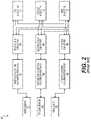
- FIG. 2is a diagram showing a prior art network distributed system for sensor data acquisition, in an embodiment
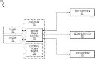
- FIG. 3is a diagram showing a remote sensor data acquisition system, in an embodiment.
- Embodiments of the present disclosureprovide a remote sensor data acquisition system that uses a plurality of serial peripheral interface (SPI) buses to operate each sensor remotely and to provide sensor data to a plurality of control devices simultaneously and in real time.
- Embodiments of the present disclosurealso allow multiple sensor interfaces to share the same data bus for sharing sensor data with a plurality of subsystems.
- Example sensorsinclude but are not limited to light sensors used to determine a need for exterior lighting, position sensors to determine a control-wheel position, and temperature and pressure sensors to provide temperature and pressure from a turbine engine to a full-authority-digital-engine-control (FADEC) subsystem.
- FADECfull-authority-digital-engine-control
- Example subsystemsinclude but are not limited to entertainment subsystems, HVAC subsystems, lighting subsystems (e.g., exterior and cabin), environmental subsystems, pitch, roll, and yaw control subsystems, spoiler subsystems, flap subsystems, rudder subsystems, horizontal stabilizer subsystems, hydraulic subsystems, landing gear subsystems, a FADEC subsystem, and navigational subsystems. Additionally, the sensor data may be used to determine aircraft control variables such as weight-on-wheels, angle-of-attack, Mach number, dynamic pressure, etc.
- FIG. 1is a diagram showing a prior art system 100 for sensor data acquisition.
- System 100includes a plurality of N sensors used to measure one or more parameters and provide measurement data from the plurality of N sensors to a plurality of M subsystems, where N and M are non-negative integers.
- a key feature of system 100is that each sensor communicates with a subsystem via a dedicated channel for each parameter measured.
- each of the plurality of N sensorsis adapted to measure a single parameter, which may be the same for each of the plurality of N sensors or the plurality of N sensors may be used to measure different parameters.
- Exemplary parametersinclude light intensity, position, velocity, acceleration, humidity, temperature, pressure, fluid level etc.
- the plurality of N sensorsincludes a first sensor 101 , a second sensor 102 , and so on up to an Nth sensor 109 .
- the first sensor 101is communicatively coupled with a first subsystem 111 via a first data acquisition and sensor interface 121
- the second sensor 102is communicatively coupled with a second subsystem 112 via a second data acquisition and sensor interface 122
- the Nth sensor 109which is communicatively coupled with an Mth subsystem 119 via an Mth data acquisition and sensor interface 129
- Nequals M such that each sensor is communicatively coupled with a respective subsystem.
- Nis greater than M such that more than one sensor is communicatively coupled to a subsystem.
- Exchange of data (e.g., local sensor values) between each pair of subsystemsis performed by a device adapted to transfer data between different components, such as an exchange bus.
- a first exchange bus 131is used to exchange data between first data acquisition and sensor interface 121 and second data acquisition and sensor interface 122 .
- subsystem 111is a full-authority-digital-engine-control (FADEC) Channel A
- subsystem 112is a FADEC Channel B.
- Sensors 101 and 102are independent throttle lever angle measurement devices.
- FADEC Channel A and FADEC Channel Btrade data from sensors 101 and 102 over data exchange bus 131 .
- a second exchange bus 132may be used to exchange data between second data acquisition and sensor interface 122 and Mth data acquisition and sensor interface 129 , and so on.
- remote sensorsare located distally from subsystems that receive sensor data.
- engine-indicating sensorsare located in an aircraft engine while a flight controller that receives engine-indicating data may be located in a cockpit.
- the data acquisition and sensor interfacesare co-located with the subsystems. This configuration requires a large number of wires to be run a relatively longer distance from the sensors to the data acquisition and sensor interfaces which causes a weight penalty and environmental complications due to electromagnetic interference (EMI).
- EMIelectromagnetic interference
- System 100includes additional disadvantages such as a high cost associated with a large number of sensors and associated connections. Additionally, comparison of data between sensors measuring the same parameter introduces an uncertainty.
- each subsystemis configured independently, arrival times of data transferred between any of the subsystems (e.g., via exchange buses) is not guaranteed and the sensor data may be randomly old.
- parameters being measurede.g., direction and speed
- correlation between the sensorsis much more difficult to achieve due to a transfer repetition rate of sensor data on cross-channel buses.
- System 100also provides an inherent reliance on subsystem communication for sensor data.
- first subsystem 111e.g., a FADEC channel A
- second subsystem 112e.g., a FADEC channel B
- each subsystemrelies on the other for data from its respective throttle-lever-angle sensor.
- FIG. 2is a diagram showing a prior art network distributed system 200 for sensor data acquisition. Similar to system 100 , one or more parameters are measured with the plurality of N sensors 101 - 109 . As depicted in the embodiment of FIG. 2 , each of the plurality of N sensors 101 - 109 is communicatively coupled via a dedicated channel with a respective one of the plurality of M data acquisition and sensor interfaces 121 - 129 . A plurality of Input/Output (I/O) bus converters 141 , 142 , . . . 149 enable sensor data to be shared between subsystems. Similar to system 100 , system 200 may include the same number of sensors as subsystems (N equals M), or a greater number of sensors may be included (N is greater than M), without departing from the scope hereof.
- I/OInput/Output
- system 200may be located closer to one or more sensors compared to system 100 .
- system 200also includes disadvantages such as the high cost associated with a large number of sensors and associated connections that redundantly measure the same parameter. Because each subsystem is independent, arrival times of data transferred between any of the subsystems is not guaranteed. When parameters being measured are rapidly changing, correlation of data between redundant sensors is much more difficult due to a transfer repetition rate of sensor data on cross-channel buses.
- FIG. 3is a diagram showing a remote sensor data acquisition system 300 .
- System 300may be provided onboard an aircraft/rotorcraft, in an automobile, in a home or other building, and with heating, ventilation, and air conditioning (HVAC) systems. Additionally, system 300 may be used with entertainment systems and internet-of-things (IoT) devices, in which subsystems include remote sensors such that the devices (e.g., lights, furnace, humidifier, and position indicators for garage door closed or main door locked, etc.) may be controlled from a computer without requiring Internet access.
- IoTinternet-of-things
- system 300uses fewer sensors for a given parameter to be measured and each subsystem is independent of every other subsystem. At least one remote sensor is used per parameter to be measured. In certain embodiments, a single sensor is used to measure each parameter. In some embodiments intended for providing critical data (e.g., onboard aircraft), redundant sensors are preferred to avoid failure modes resulting from faulty or missing sensor data. For example, duplicate sensors may be used to measure the same parameter at one location. Alternatively, three or more redundant sensors may be used with a voting algorithm to exclude faulty or missing data from a minority of sensors.
- duplicate sensorsare provided (e.g., sensor 301 and sensor 302 ) as an example of redundant sensors measuring the same parameter in substantially the same location (e.g., two engine-indicating sensors measuring the same parameter at the same aircraft engine).
- a remote sensor interface 321is locally provided with sensor 301 and sensor 302 , meaning that remote sensor interface 321 is located in substantially the same location as sensor 301 and sensor 302 (e.g., at or near the engine).
- remote sensor interface 321is physically co-located with sensors 301 and 302 .
- remote sensor interface 321is provided in a convenient mounting location that is in immediate proximity with sensors 301 and 302 .
- Remote sensor interface 321is for example a communication bus adapted to accommodate a plurality of nodes. This enables remote sensor interface 321 to make available sensor data (e.g., from sensors 301 and 302 ) for transmitting to a plurality of subsystems (e.g., subsystems 1 , 2 , . . . M) independently, simultaneously and in real time.
- sensor datae.g., from sensors 301 and 302
- subsystemse.g., subsystems 1 , 2 , . . . M
- first subsystem 111e.g., FADEC channel A
- second subsystem 112e.g., FADEC channel B
- first subsystem 111e.g., FADEC channel A
- second subsystem 112e.g., FADEC channel B
- Providing data independenceis an important criterion for safety-critical systems.
- the plurality of nodes within remote sensor interface 321include a plurality of serial peripheral interface (SPI) buses.
- the plurality of SPIsmay include an SPI for each of the M subsystems, respectively.
- the SPIshave been hardened to withstand challenging environments (e.g., a flight environment) and may be powered independently (e.g., via dedicated batteries).
- the plurality of SPIsmake sensor data accessible to M subsystems (e.g., control devices) and transmit the sensor data simultaneously and in real time.
- SPIsprovide uni-directional connections and can be buffered for flow in one direction, and no bits are added to the data sent for clock recovery. These features simplify implementation with standard register gates, reducing overhead.
- the interface hardwareis reusable and may easily be modified to work with a variety of sensor types whose output can be converted and transmitted on multiple digital data buses.
- an additional remote sensor interfaceis provided for each location (not shown).
- a first plurality of sensorsmay be co-located in a first location for measuring one or more parameters.
- a first remote sensor interfaceis co-located in the first location with the first plurality of sensors.
- the first remote sensor interfaceprovides data from each of the first plurality of sensors independently to a plurality of subsystems in a first time slot.
- a second plurality of sensorsis co-located in a second location, distal from the first location, for measuring one or more parameters.
- a second remote sensor interfaceis co-located in the second location with the second plurality of sensors, the second remote sensor interface being adapted to provide data from each of the second plurality of sensors independently to the plurality of subsystems in a second time slot different from the first time slot. Regardless of the number of remote sensor interfaces, they may each communicate independently with each of the plurality of subsystems.
- remote sensor interface 321is located within an enclosure 351 (e.g., a metallic enclosure) that includes a source of electrical power for powering remote sensor interface 321 and signal processing circuitry (e.g., for filtering/conditioning sensor signals, and for converting analog signals to digital signals).
- the enclosurealso includes circuitry for excitation of sensors 301 and 302 and for receiving feedback from sensors 301 and 302 , as further described in the example below.
- a number of wires running to sensors 301 and 302 from the metallic enclosuremay exceed those running to each of subsystems 111 - 119 .
- Having fewer wires running to the subsystems 111 - 119further incentivizes locating remote sensor interface 321 in proximity with sensors 301 and 302 and distant from the subsystems 111 - 119 .
- a significant weight savingsmay be realized by arranging larger wire bundles to have shorter lengths, which not only reduces weight but also reduces environmental issues such as EMI.
- sensors 301 and 302form a dual rotary-variable-differential transformer (RVDT) package located at a control wheel for sensing a position of the control wheel in duplicate.
- Remote sensor interface 321is located in proximity with the control wheel and electrical power source 361 provides an excitation voltage to primary coils of each RVDT. Secondary coils of the RVDTs receive a feedback signal indicative of a position of the control wheel. The feedback signal is received by remote sensor interface 321 after passing through conditioning, an analog arithmetic circuit, and an analog-to-digital converter to digitize the feedback signal.
- the digitized feedback signalis made available by remote sensor interface 321 via independent SPI buses such that both values (e.g., positions) from sensors 301 and 302 are made available simultaneously and in real time. Inputs and outputs of the SPI buses are buffered and protected from outside interference (e.g., noise and effects from lightning).
- the SPI busesallow multiple subsystems to access duplicate control wheel position data for use in control algorithms.
- the SPI buses of remote sensor interface 321are adapted to accommodate multiple sensor units, which enables data sharing from multiple sensors connected with each SPI bus.
- a remote sensor interfacemay share a set of control wheel position data (e.g., from duplicate sensors) and control lever position data on the same SPI bus and provide both sets of data to the same subsystem (e.g., a flight control subsystem).
- system 300is used to perform a method that measures a parameter using at least one remote sensor (e.g., sensor 301 ).
- a remote sensor interfacee.g., remote sensor interface 321
- a remote sensor interfaceis co-located with the at least one remote sensor and includes a communication bus adapted to accommodate a plurality of nodes.
- Dataare transmitted from the at least one sensor to a plurality of subsystems (e.g., subsystems 111 - 119 ) via the plurality of nodes simultaneously and in real time.
- transmitting of data from the at least one sensorincludes transferring data to the plurality of subsystems with guaranteed arrival times for ensuring the data are fresh.
- rapidly changing dataare correlated between redundant sensors at the remote sensor interface to avoid latency of the data.
- One or more parametersmay be measured using at least one remote sensor per parameter.
- the one or more parametersmay include light intensity, position, velocity, acceleration, humidity, temperature, pressure, and fluid level.
- Transmitting sensor data to a subsystemmay include transmitting data to at least one of a lighting subsystem, a pitch-control subsystem, a roll-control subsystem, a yaw-control subsystem, a FADEC subsystem, and a navigational subsystem. Accessing data via the plurality of subsystems occurs from the at least one remote sensor within appropriate time slots. Providing data from the at least one sensor to a plurality of channels of embedded control maintains independence and reduces latency.
- Advantages of system 300include cost reductions due to a substantial reduction in the number of sensors used to provide adequate measurement of a given parameter for a critical system while maintaining functional independence.
- the reduced number of sensorsalso provides a reduction in data conversion steps from each sensor to a control subsystem. Independent measurement is maintained by each sensor while providing data from the respective sensor to a plurality of channels of embedded control, thereby maintaining independence and reducing latency.
- No programmingis required for different implementations of remote sensor interface 321 .
- the resulting embedded electronicsprovide a more generic architecture, needing only to interface with a digital bus, therefore requiring less design effort and being applicable to multiple configurations.
- Timing uncertainty of the parameter measurementsis eliminated because each subsystem may access any sensor at the appropriate time slot and each subsystem receives signals from all of the sensors within appropriate time slots.
- Each subsystemis independent and the arrival time of data transferred to any of the subsystems is guaranteed, ensuring that the data are fresh. In other words, the age of the data is only the time needed for data transfer from the sensors.
- the correlation between sensorsoccurs at the remote sensor interface, which simplifies the correlation because latency (e.g., latency of transfer repetition rate) has been eliminated.
- no subsystemmay deny access to any sensor by any other subsystem. For example, no wiring fault or subsystem crash may deny any subsystem access to any sensor.
Landscapes
- Engineering & Computer Science (AREA)
- Computer Networks & Wireless Communication (AREA)
- Signal Processing (AREA)
- Health & Medical Sciences (AREA)
- Computing Systems (AREA)
- General Health & Medical Sciences (AREA)
- Medical Informatics (AREA)
- Aviation & Aerospace Engineering (AREA)
- Manufacturing & Machinery (AREA)
- Transportation (AREA)
- Arrangements For Transmission Of Measured Signals (AREA)
Abstract
Description
Claims (19)
Priority Applications (1)
| Application Number | Priority Date | Filing Date | Title |
|---|---|---|---|
| US16/225,056US11528165B2 (en) | 2018-01-19 | 2018-12-19 | Remote sensor data acquisition |
Applications Claiming Priority (2)
| Application Number | Priority Date | Filing Date | Title |
|---|---|---|---|
| US201862619272P | 2018-01-19 | 2018-01-19 | |
| US16/225,056US11528165B2 (en) | 2018-01-19 | 2018-12-19 | Remote sensor data acquisition |
Publications (2)
| Publication Number | Publication Date |
|---|---|
| US20190229947A1 US20190229947A1 (en) | 2019-07-25 |
| US11528165B2true US11528165B2 (en) | 2022-12-13 |
Family
ID=67299488
Family Applications (1)
| Application Number | Title | Priority Date | Filing Date |
|---|---|---|---|
| US16/225,056ActiveUS11528165B2 (en) | 2018-01-19 | 2018-12-19 | Remote sensor data acquisition |
Country Status (1)
| Country | Link |
|---|---|
| US (1) | US11528165B2 (en) |
Cited By (1)
| Publication number | Priority date | Publication date | Assignee | Title |
|---|---|---|---|---|
| US20250108936A1 (en)* | 2023-09-29 | 2025-04-03 | General Electric Company | Aircraft monitoring system |
Families Citing this family (2)
| Publication number | Priority date | Publication date | Assignee | Title |
|---|---|---|---|---|
| US11882508B2 (en)* | 2020-03-23 | 2024-01-23 | Sap Se | Data processing system for smart devices |
| CN111963322A (en)* | 2020-08-26 | 2020-11-20 | 四川海特亚美航空技术有限公司 | Turboshaft engine binary channels electronic control system data acquisition system |
Citations (23)
| Publication number | Priority date | Publication date | Assignee | Title |
|---|---|---|---|---|
| US6035240A (en) | 1998-11-12 | 2000-03-07 | Moorehead; Jack | Flexible distributed processing system for sensor data acquisition and control |
| US6047222A (en) | 1996-10-04 | 2000-04-04 | Fisher Controls International, Inc. | Process control network with redundant field devices and buses |
| US6760309B1 (en)* | 2000-03-28 | 2004-07-06 | 3Com Corporation | Method of dynamic prioritization of time sensitive packets over a packet based network |
| US20080162972A1 (en)* | 2006-12-29 | 2008-07-03 | Yen-Cheng Liu | Optimizing power usage by factoring processor architecutral events to pmu |
| US20090222148A1 (en)* | 2006-06-21 | 2009-09-03 | Calspan Corporation | Autonomous Outer Loop Control of Man-Rated Fly-By-Wire Aircraft |
| US20100025544A1 (en)* | 2006-10-12 | 2010-02-04 | Beaufrere Henry L | Aircraft backup control |
| US20120016623A1 (en)* | 2010-07-19 | 2012-01-19 | Hayner David A | Use of Multiple Internal Sensors for Measurement Validation |
| US20120176124A1 (en)* | 2011-01-07 | 2012-07-12 | Woodward Mpc, Inc. | Method and Apparatus for a Half-Bridge Variable Differential Transformer Position Sensing System |
| US8311778B2 (en) | 2009-09-22 | 2012-11-13 | Rosemount Inc. | Industrial process control transmitter with multiple sensors |
| US20140067192A1 (en)* | 2012-08-28 | 2014-03-06 | GM Global Technology Operations LLC | Active safety systems of vehicles with graphical microprocessors |
| US20140281130A1 (en)* | 2013-03-15 | 2014-09-18 | The Boeing Company | Accessing non-volatile memory through a volatile shadow memory |
| US20140297155A1 (en)* | 2012-07-12 | 2014-10-02 | Pratt & Whitney Canada Corp. | Aircraft power outtake management |
| US20140365702A1 (en)* | 2013-06-05 | 2014-12-11 | The Boeing Company | Sensor network using pulse width modulated signals |
| US20150042321A1 (en)* | 2012-01-27 | 2015-02-12 | Kavlico Corporation | Rotary variable differential transformer (rvdt) sensor assembly with auxiliary output signal |
| US20160214730A1 (en)* | 2013-08-29 | 2016-07-28 | Bombardier Inc. | Electronic throttle system for an aircraft |
| US20160334786A1 (en)* | 2015-05-14 | 2016-11-17 | Honeywell International Inc. | External aircraft ground control |
| US20170168975A1 (en)* | 2014-09-09 | 2017-06-15 | Fujitsu Limited | Modular Computer System, Server Module and Rack Arrangement |
| US20170208420A1 (en)* | 2016-01-20 | 2017-07-20 | Desheng Wang | Universal smart device |
| US20180284735A1 (en)* | 2016-05-09 | 2018-10-04 | StrongForce IoT Portfolio 2016, LLC | Methods and systems for industrial internet of things data collection in a network sensitive upstream oil and gas environment |
| US20180288080A1 (en)* | 2017-03-31 | 2018-10-04 | The Boeing Company | On-board networked anomaly detection (onad) modules |
| US20190109600A1 (en)* | 2017-10-10 | 2019-04-11 | The Boeing Company | Data collection device with efficient data compression |
| US20190112050A1 (en)* | 2017-10-17 | 2019-04-18 | The Boeing Company | Artificially intelligent flight crew systems and methods |
| US20190163178A1 (en)* | 2017-11-29 | 2019-05-30 | Nio Usa, Inc. | Method and apparatus for simultaneous processing and logging of automotive vision system with controls and fault monitoring |
- 2018
- 2018-12-19USUS16/225,056patent/US11528165B2/enactiveActive
Patent Citations (23)
| Publication number | Priority date | Publication date | Assignee | Title |
|---|---|---|---|---|
| US6047222A (en) | 1996-10-04 | 2000-04-04 | Fisher Controls International, Inc. | Process control network with redundant field devices and buses |
| US6035240A (en) | 1998-11-12 | 2000-03-07 | Moorehead; Jack | Flexible distributed processing system for sensor data acquisition and control |
| US6760309B1 (en)* | 2000-03-28 | 2004-07-06 | 3Com Corporation | Method of dynamic prioritization of time sensitive packets over a packet based network |
| US20090222148A1 (en)* | 2006-06-21 | 2009-09-03 | Calspan Corporation | Autonomous Outer Loop Control of Man-Rated Fly-By-Wire Aircraft |
| US20100025544A1 (en)* | 2006-10-12 | 2010-02-04 | Beaufrere Henry L | Aircraft backup control |
| US20080162972A1 (en)* | 2006-12-29 | 2008-07-03 | Yen-Cheng Liu | Optimizing power usage by factoring processor architecutral events to pmu |
| US8311778B2 (en) | 2009-09-22 | 2012-11-13 | Rosemount Inc. | Industrial process control transmitter with multiple sensors |
| US20120016623A1 (en)* | 2010-07-19 | 2012-01-19 | Hayner David A | Use of Multiple Internal Sensors for Measurement Validation |
| US20120176124A1 (en)* | 2011-01-07 | 2012-07-12 | Woodward Mpc, Inc. | Method and Apparatus for a Half-Bridge Variable Differential Transformer Position Sensing System |
| US20150042321A1 (en)* | 2012-01-27 | 2015-02-12 | Kavlico Corporation | Rotary variable differential transformer (rvdt) sensor assembly with auxiliary output signal |
| US20140297155A1 (en)* | 2012-07-12 | 2014-10-02 | Pratt & Whitney Canada Corp. | Aircraft power outtake management |
| US20140067192A1 (en)* | 2012-08-28 | 2014-03-06 | GM Global Technology Operations LLC | Active safety systems of vehicles with graphical microprocessors |
| US20140281130A1 (en)* | 2013-03-15 | 2014-09-18 | The Boeing Company | Accessing non-volatile memory through a volatile shadow memory |
| US20140365702A1 (en)* | 2013-06-05 | 2014-12-11 | The Boeing Company | Sensor network using pulse width modulated signals |
| US20160214730A1 (en)* | 2013-08-29 | 2016-07-28 | Bombardier Inc. | Electronic throttle system for an aircraft |
| US20170168975A1 (en)* | 2014-09-09 | 2017-06-15 | Fujitsu Limited | Modular Computer System, Server Module and Rack Arrangement |
| US20160334786A1 (en)* | 2015-05-14 | 2016-11-17 | Honeywell International Inc. | External aircraft ground control |
| US20170208420A1 (en)* | 2016-01-20 | 2017-07-20 | Desheng Wang | Universal smart device |
| US20180284735A1 (en)* | 2016-05-09 | 2018-10-04 | StrongForce IoT Portfolio 2016, LLC | Methods and systems for industrial internet of things data collection in a network sensitive upstream oil and gas environment |
| US20180288080A1 (en)* | 2017-03-31 | 2018-10-04 | The Boeing Company | On-board networked anomaly detection (onad) modules |
| US20190109600A1 (en)* | 2017-10-10 | 2019-04-11 | The Boeing Company | Data collection device with efficient data compression |
| US20190112050A1 (en)* | 2017-10-17 | 2019-04-18 | The Boeing Company | Artificially intelligent flight crew systems and methods |
| US20190163178A1 (en)* | 2017-11-29 | 2019-05-30 | Nio Usa, Inc. | Method and apparatus for simultaneous processing and logging of automotive vision system with controls and fault monitoring |
Cited By (1)
| Publication number | Priority date | Publication date | Assignee | Title |
|---|---|---|---|---|
| US20250108936A1 (en)* | 2023-09-29 | 2025-04-03 | General Electric Company | Aircraft monitoring system |
Also Published As
| Publication number | Publication date |
|---|---|
| US20190229947A1 (en) | 2019-07-25 |
Similar Documents
| Publication | Publication Date | Title |
|---|---|---|
| US11528165B2 (en) | Remote sensor data acquisition | |
| US10065583B2 (en) | Integrated power distribution, data network, and control architectures for a vehicle | |
| US8036805B2 (en) | Distributed engine control system | |
| US8600583B2 (en) | Distributed flight control system | |
| RU2670941C9 (en) | Dual-channel architecture with ccdl excess links | |
| US5809220A (en) | Fault tolerant distributed control system | |
| EP3210889B1 (en) | Wireless aircraft cabin pressure control system utilizing smart pressure sensors | |
| US20170355449A1 (en) | Electrical architecture for slat/flap control using smart sensors and effectors | |
| EP2394417B1 (en) | Aircraft hybrid cockpit control panel system | |
| US20130179622A1 (en) | System and method for transmitting and receiving data using an industrial expansion bus | |
| JP2014527209A (en) | Dynamically reconfigurable electrical interface | |
| WO2023045067A1 (en) | Flight control unit, aircraft control system and method, and aircraft | |
| US8903569B2 (en) | Method for controlling a high-lift device or a flight control surface, system and aircraft or spacecraft | |
| US8370004B2 (en) | Control panel for an aircraft | |
| CN102422599B (en) | Control architecture and interface method for cockpit control panel system | |
| EP3447502A1 (en) | Air data system architectures using integrated pressure probes | |
| CA3028053A1 (en) | Aircraft communication system and protocol | |
| EP2077477B1 (en) | Failsafe remote data concentrator | |
| Jose | An FPGA implementation of 1553 protocol controller | |
| CN110466741A (en) | System for controlling, adjusting and/or monitor aviation aircraft | |
| Song et al. | Study of a vehicular drive-by-wire system based on FlexRay protocol | |
| KR102579809B1 (en) | Apparatus for real-time storage | |
| Antunes et al. | A modular CAN based data acquisition system for flight simulators | |
| Xin et al. | Typical Redundancy Architecture Design of UAV Flight Control System | |
| Zhang et al. | Design of a real-time substation communication system for integrated protection |
Legal Events
| Date | Code | Title | Description |
|---|---|---|---|
| AS | Assignment | Owner name:TEXTRON AVIATION INC., KANSAS Free format text:ASSIGNMENT OF ASSIGNORS INTEREST;ASSIGNORS:OHOL, JOSEPH ANDREW;YOUNG, ROBIN L.;REEL/FRAME:047814/0157 Effective date:20181210 | |
| FEPP | Fee payment procedure | Free format text:ENTITY STATUS SET TO UNDISCOUNTED (ORIGINAL EVENT CODE: BIG.); ENTITY STATUS OF PATENT OWNER: LARGE ENTITY | |
| AS | Assignment | Owner name:TEXTRON AVIATION RHODE ISLAND INC., RHODE ISLAND Free format text:ASSIGNMENT OF ASSIGNORS INTEREST;ASSIGNOR:TEXTRON AVIATION INC.;REEL/FRAME:048560/0420 Effective date:20190110 Owner name:TEXTRON INNOVATIONS, INC., RHODE ISLAND Free format text:ASSIGNMENT OF ASSIGNORS INTEREST;ASSIGNOR:TEXTRON AVIATION RHODE ISLAND INC.;REEL/FRAME:048560/0606 Effective date:20190110 | |
| STPP | Information on status: patent application and granting procedure in general | Free format text:NON FINAL ACTION MAILED | |
| STPP | Information on status: patent application and granting procedure in general | Free format text:FINAL REJECTION MAILED | |
| STPP | Information on status: patent application and granting procedure in general | Free format text:NON FINAL ACTION MAILED | |
| STPP | Information on status: patent application and granting procedure in general | Free format text:RESPONSE TO NON-FINAL OFFICE ACTION ENTERED AND FORWARDED TO EXAMINER | |
| STPP | Information on status: patent application and granting procedure in general | Free format text:FINAL REJECTION MAILED | |
| STPP | Information on status: patent application and granting procedure in general | Free format text:DOCKETED NEW CASE - READY FOR EXAMINATION | |
| STPP | Information on status: patent application and granting procedure in general | Free format text:NON FINAL ACTION MAILED | |
| STPP | Information on status: patent application and granting procedure in general | Free format text:RESPONSE TO NON-FINAL OFFICE ACTION ENTERED AND FORWARDED TO EXAMINER | |
| STPP | Information on status: patent application and granting procedure in general | Free format text:FINAL REJECTION MAILED | |
| STPP | Information on status: patent application and granting procedure in general | Free format text:RESPONSE AFTER FINAL ACTION FORWARDED TO EXAMINER | |
| STPP | Information on status: patent application and granting procedure in general | Free format text:NOTICE OF ALLOWANCE MAILED -- APPLICATION RECEIVED IN OFFICE OF PUBLICATIONS | |
| STPP | Information on status: patent application and granting procedure in general | Free format text:NOTICE OF ALLOWANCE MAILED -- APPLICATION RECEIVED IN OFFICE OF PUBLICATIONS | |
| STPP | Information on status: patent application and granting procedure in general | Free format text:PUBLICATIONS -- ISSUE FEE PAYMENT VERIFIED | |
| STCF | Information on status: patent grant | Free format text:PATENTED CASE |