US11524147B2 - Valve system for inflatable devices - Google Patents
Valve system for inflatable devicesDownload PDFInfo
- Publication number
- US11524147B2 US11524147B2US17/071,342US202017071342AUS11524147B2US 11524147 B2US11524147 B2US 11524147B2US 202017071342 AUS202017071342 AUS 202017071342AUS 11524147 B2US11524147 B2US 11524147B2
- Authority
- US
- United States
- Prior art keywords
- pressure
- valve
- inflatable portion
- relief valve
- pressure relief
- Prior art date
- Legal status (The legal status is an assumption and is not a legal conclusion. Google has not performed a legal analysis and makes no representation as to the accuracy of the status listed.)
- Active
Links
- 239000012530fluidSubstances0.000claimsdescription96
- 238000005336crackingMethods0.000claimsdescription63
- 238000000034methodMethods0.000claimsdescription33
- 238000004891communicationMethods0.000claimsdescription14
- 230000001419dependent effectEffects0.000claimsdescription5
- 230000000007visual effectEffects0.000claimsdescription5
- 230000014759maintenance of locationEffects0.000abstractdescription82
- 230000010354integrationEffects0.000abstractdescription3
- 230000002550fecal effectEffects0.000description19
- 238000007789sealingMethods0.000description10
- 230000002485urinary effectEffects0.000description8
- XLYOFNOQVPJJNP-UHFFFAOYSA-NwaterSubstancesOXLYOFNOQVPJJNP-UHFFFAOYSA-N0.000description8
- 239000007788liquidSubstances0.000description6
- 229920003052natural elastomerPolymers0.000description6
- 229920001194natural rubberPolymers0.000description6
- 239000000806elastomerSubstances0.000description5
- 238000003780insertionMethods0.000description5
- 230000037431insertionEffects0.000description5
- -1polyethylenePolymers0.000description5
- 229920001296polysiloxanePolymers0.000description5
- 238000012360testing methodMethods0.000description5
- 244000043261Hevea brasiliensisSpecies0.000description4
- 239000004676acrylonitrile butadiene styreneSubstances0.000description4
- 239000003814drugSubstances0.000description4
- 229920001971elastomerPolymers0.000description4
- 239000000463materialSubstances0.000description4
- ORQBXQOJMQIAOY-UHFFFAOYSA-NnobeliumChemical compound[No]ORQBXQOJMQIAOY-UHFFFAOYSA-N0.000description4
- 239000002699waste materialSubstances0.000description4
- 239000004677NylonSubstances0.000description3
- 230000008901benefitEffects0.000description3
- 230000005294ferromagnetic effectEffects0.000description3
- 239000006260foamSubstances0.000description3
- 208000015181infectious diseaseDiseases0.000description3
- 238000012423maintenanceMethods0.000description3
- 229920001778nylonPolymers0.000description3
- 230000002265preventionEffects0.000description3
- 229910001220stainless steelInorganic materials0.000description3
- 239000010935stainless steelSubstances0.000description3
- 239000004215Carbon black (E152)Substances0.000description2
- 206010011224CoughDiseases0.000description2
- 208000018672DilatationDiseases0.000description2
- 208000034347Faecal incontinenceDiseases0.000description2
- 239000002033PVDF binderSubstances0.000description2
- 241000405070PercophidaeSpecies0.000description2
- 239000004698PolyethyleneSubstances0.000description2
- 239000004743PolypropyleneSubstances0.000description2
- 208000004210Pressure UlcerDiseases0.000description2
- DHKHKXVYLBGOIT-UHFFFAOYSA-Nacetaldehyde Diethyl AcetalNatural productsCCOC(C)OCCDHKHKXVYLBGOIT-UHFFFAOYSA-N0.000description2
- 125000002777acetyl groupChemical class[H]C([H])([H])C(*)=O0.000description2
- 210000004204blood vesselAnatomy0.000description2
- 230000001276controlling effectEffects0.000description2
- 230000008878couplingEffects0.000description2
- 238000010168coupling processMethods0.000description2
- 238000005859coupling reactionMethods0.000description2
- 229940079593drugDrugs0.000description2
- 229920002313fluoropolymerPolymers0.000description2
- 239000004811fluoropolymerSubstances0.000description2
- 229920005560fluorosilicone rubberPolymers0.000description2
- 210000001035gastrointestinal tractAnatomy0.000description2
- 230000009931harmful effectEffects0.000description2
- 229930195733hydrocarbonNatural products0.000description2
- 150000002430hydrocarbonsChemical class0.000description2
- 230000003993interactionEffects0.000description2
- 230000002262irrigationEffects0.000description2
- 238000003973irrigationMethods0.000description2
- 239000002184metalSubstances0.000description2
- 230000017074necrotic cell deathEffects0.000description2
- 230000037361pathwayEffects0.000description2
- 229920000573polyethylenePolymers0.000description2
- 229920001155polypropylenePolymers0.000description2
- 229920002981polyvinylidene fluoridePolymers0.000description2
- 210000000664rectumAnatomy0.000description2
- 208000017520skin diseaseDiseases0.000description2
- 210000004872soft tissueAnatomy0.000description2
- 229920003051synthetic elastomerPolymers0.000description2
- 210000001519tissueAnatomy0.000description2
- 230000001960triggered effectEffects0.000description2
- 210000000626ureterAnatomy0.000description2
- 241000894006BacteriaSpecies0.000description1
- 241000193163Clostridioides difficileSpecies0.000description1
- 208000034656ContusionsDiseases0.000description1
- 206010011469CryingDiseases0.000description1
- 206010011985Decubitus ulcerDiseases0.000description1
- 206010012735DiarrhoeaDiseases0.000description1
- 206010021639IncontinenceDiseases0.000description1
- 229920000079Memory foamPolymers0.000description1
- 229920005830Polyurethane FoamPolymers0.000description1
- FAPWRFPIFSIZLT-UHFFFAOYSA-MSodium chlorideChemical compound[Na+].[Cl-]FAPWRFPIFSIZLT-UHFFFAOYSA-M0.000description1
- 208000025865UlcerDiseases0.000description1
- 206010052428WoundDiseases0.000description1
- 208000027418Wounds and injuryDiseases0.000description1
- 230000002159abnormal effectEffects0.000description1
- 230000008081blood perfusionEffects0.000description1
- 239000000919ceramicSubstances0.000description1
- 230000008859changeEffects0.000description1
- 238000011109contaminationMethods0.000description1
- 230000008602contractionEffects0.000description1
- 238000013461designMethods0.000description1
- 238000011161developmentMethods0.000description1
- 239000013013elastic materialSubstances0.000description1
- 238000002474experimental methodMethods0.000description1
- 230000006870functionEffects0.000description1
- 238000010348incorporationMethods0.000description1
- 230000002458infectious effectEffects0.000description1
- 230000002452interceptive effectEffects0.000description1
- 238000002595magnetic resonance imagingMethods0.000description1
- 238000005259measurementMethods0.000description1
- 239000012528membraneSubstances0.000description1
- 239000008210memory foamSubstances0.000description1
- 229910052753mercuryInorganic materials0.000description1
- 210000000056organAnatomy0.000description1
- 230000008855peristalsisEffects0.000description1
- 239000004033plasticSubstances0.000description1
- 229920003023plasticPolymers0.000description1
- 239000011496polyurethane foamSubstances0.000description1
- 230000001105regulatory effectEffects0.000description1
- 239000005060rubberSubstances0.000description1
- 206010041232sneezingDiseases0.000description1
- 238000006467substitution reactionMethods0.000description1
- 230000000451tissue damageEffects0.000description1
- 231100000827tissue damageToxicity0.000description1
- 230000036269ulcerationEffects0.000description1
Images


Classifications
- A—HUMAN NECESSITIES
- A61—MEDICAL OR VETERINARY SCIENCE; HYGIENE
- A61M—DEVICES FOR INTRODUCING MEDIA INTO, OR ONTO, THE BODY; DEVICES FOR TRANSDUCING BODY MEDIA OR FOR TAKING MEDIA FROM THE BODY; DEVICES FOR PRODUCING OR ENDING SLEEP OR STUPOR
- A61M25/00—Catheters; Hollow probes
- A61M25/10—Balloon catheters
- A61M25/1018—Balloon inflating or inflation-control devices
- A61M25/10184—Means for controlling or monitoring inflation or deflation
- A61M25/10185—Valves
- A61M25/10186—One-way valves
- A—HUMAN NECESSITIES
- A61—MEDICAL OR VETERINARY SCIENCE; HYGIENE
- A61F—FILTERS IMPLANTABLE INTO BLOOD VESSELS; PROSTHESES; DEVICES PROVIDING PATENCY TO, OR PREVENTING COLLAPSING OF, TUBULAR STRUCTURES OF THE BODY, e.g. STENTS; ORTHOPAEDIC, NURSING OR CONTRACEPTIVE DEVICES; FOMENTATION; TREATMENT OR PROTECTION OF EYES OR EARS; BANDAGES, DRESSINGS OR ABSORBENT PADS; FIRST-AID KITS
- A61F5/00—Orthopaedic methods or devices for non-surgical treatment of bones or joints; Nursing devices ; Anti-rape devices
- A61F5/0093—Rectal devices, e.g. for the treatment of haemorrhoids
- A—HUMAN NECESSITIES
- A61—MEDICAL OR VETERINARY SCIENCE; HYGIENE
- A61F—FILTERS IMPLANTABLE INTO BLOOD VESSELS; PROSTHESES; DEVICES PROVIDING PATENCY TO, OR PREVENTING COLLAPSING OF, TUBULAR STRUCTURES OF THE BODY, e.g. STENTS; ORTHOPAEDIC, NURSING OR CONTRACEPTIVE DEVICES; FOMENTATION; TREATMENT OR PROTECTION OF EYES OR EARS; BANDAGES, DRESSINGS OR ABSORBENT PADS; FIRST-AID KITS
- A61F5/00—Orthopaedic methods or devices for non-surgical treatment of bones or joints; Nursing devices ; Anti-rape devices
- A61F5/44—Devices worn by the patient for reception of urine, faeces, catamenial or other discharge; Colostomy devices
- A61F5/4404—Details or parts
- A61F5/4405—Valves or valve arrangements specially adapted therefor ; Fluid inlets or outlets
- A—HUMAN NECESSITIES
- A61—MEDICAL OR VETERINARY SCIENCE; HYGIENE
- A61F—FILTERS IMPLANTABLE INTO BLOOD VESSELS; PROSTHESES; DEVICES PROVIDING PATENCY TO, OR PREVENTING COLLAPSING OF, TUBULAR STRUCTURES OF THE BODY, e.g. STENTS; ORTHOPAEDIC, NURSING OR CONTRACEPTIVE DEVICES; FOMENTATION; TREATMENT OR PROTECTION OF EYES OR EARS; BANDAGES, DRESSINGS OR ABSORBENT PADS; FIRST-AID KITS
- A61F5/00—Orthopaedic methods or devices for non-surgical treatment of bones or joints; Nursing devices ; Anti-rape devices
- A61F5/44—Devices worn by the patient for reception of urine, faeces, catamenial or other discharge; Colostomy devices
- A61F5/451—Genital or anal receptacles
- A—HUMAN NECESSITIES
- A61—MEDICAL OR VETERINARY SCIENCE; HYGIENE
- A61M—DEVICES FOR INTRODUCING MEDIA INTO, OR ONTO, THE BODY; DEVICES FOR TRANSDUCING BODY MEDIA OR FOR TAKING MEDIA FROM THE BODY; DEVICES FOR PRODUCING OR ENDING SLEEP OR STUPOR
- A61M16/00—Devices for influencing the respiratory system of patients by gas treatment, e.g. ventilators; Tracheal tubes
- A61M16/04—Tracheal tubes
- A61M16/0434—Cuffs
- A61M16/044—External cuff pressure control or supply, e.g. synchronisation with respiration
- A—HUMAN NECESSITIES
- A61—MEDICAL OR VETERINARY SCIENCE; HYGIENE
- A61M—DEVICES FOR INTRODUCING MEDIA INTO, OR ONTO, THE BODY; DEVICES FOR TRANSDUCING BODY MEDIA OR FOR TAKING MEDIA FROM THE BODY; DEVICES FOR PRODUCING OR ENDING SLEEP OR STUPOR
- A61M25/00—Catheters; Hollow probes
- A61M25/0017—Catheters; Hollow probes specially adapted for long-term hygiene care, e.g. urethral or indwelling catheters to prevent infections
- A—HUMAN NECESSITIES
- A61—MEDICAL OR VETERINARY SCIENCE; HYGIENE
- A61M—DEVICES FOR INTRODUCING MEDIA INTO, OR ONTO, THE BODY; DEVICES FOR TRANSDUCING BODY MEDIA OR FOR TAKING MEDIA FROM THE BODY; DEVICES FOR PRODUCING OR ENDING SLEEP OR STUPOR
- A61M25/00—Catheters; Hollow probes
- A61M25/10—Balloon catheters
- A61M25/1018—Balloon inflating or inflation-control devices
- A61M25/10184—Means for controlling or monitoring inflation or deflation
- A61M25/10187—Indicators for the level of inflation or deflation
- A—HUMAN NECESSITIES
- A61—MEDICAL OR VETERINARY SCIENCE; HYGIENE
- A61F—FILTERS IMPLANTABLE INTO BLOOD VESSELS; PROSTHESES; DEVICES PROVIDING PATENCY TO, OR PREVENTING COLLAPSING OF, TUBULAR STRUCTURES OF THE BODY, e.g. STENTS; ORTHOPAEDIC, NURSING OR CONTRACEPTIVE DEVICES; FOMENTATION; TREATMENT OR PROTECTION OF EYES OR EARS; BANDAGES, DRESSINGS OR ABSORBENT PADS; FIRST-AID KITS
- A61F5/00—Orthopaedic methods or devices for non-surgical treatment of bones or joints; Nursing devices ; Anti-rape devices
- A61F5/44—Devices worn by the patient for reception of urine, faeces, catamenial or other discharge; Colostomy devices
- A61F5/445—Colostomy, ileostomy or urethrostomy devices
- A61F2005/4455—Implantable
- A—HUMAN NECESSITIES
- A61—MEDICAL OR VETERINARY SCIENCE; HYGIENE
- A61M—DEVICES FOR INTRODUCING MEDIA INTO, OR ONTO, THE BODY; DEVICES FOR TRANSDUCING BODY MEDIA OR FOR TAKING MEDIA FROM THE BODY; DEVICES FOR PRODUCING OR ENDING SLEEP OR STUPOR
- A61M2210/00—Anatomical parts of the body
- A61M2210/10—Trunk
- A61M2210/1042—Alimentary tract
- A61M2210/1064—Large intestine
- Y—GENERAL TAGGING OF NEW TECHNOLOGICAL DEVELOPMENTS; GENERAL TAGGING OF CROSS-SECTIONAL TECHNOLOGIES SPANNING OVER SEVERAL SECTIONS OF THE IPC; TECHNICAL SUBJECTS COVERED BY FORMER USPC CROSS-REFERENCE ART COLLECTIONS [XRACs] AND DIGESTS
- Y10—TECHNICAL SUBJECTS COVERED BY FORMER USPC
- Y10T—TECHNICAL SUBJECTS COVERED BY FORMER US CLASSIFICATION
- Y10T137/00—Fluid handling
- Y10T137/3584—Inflatable article [e.g., tire filling chuck and/or stem]
- Y10T137/36—With pressure-responsive pressure-control means
- Y—GENERAL TAGGING OF NEW TECHNOLOGICAL DEVELOPMENTS; GENERAL TAGGING OF CROSS-SECTIONAL TECHNOLOGIES SPANNING OVER SEVERAL SECTIONS OF THE IPC; TECHNICAL SUBJECTS COVERED BY FORMER USPC CROSS-REFERENCE ART COLLECTIONS [XRACs] AND DIGESTS
- Y10—TECHNICAL SUBJECTS COVERED BY FORMER USPC
- Y10T—TECHNICAL SUBJECTS COVERED BY FORMER US CLASSIFICATION
- Y10T137/00—Fluid handling
- Y10T137/7722—Line condition change responsive valves
- Y10T137/7771—Bi-directional flow valves
- Y10T137/7779—Axes of ports parallel
Definitions
- Indwelling medical devicesare a common and indispensable part of medical care. Indwelling devices may be placed within a bodily organ or passage to promote drainage of fluid matter from the body, for example, via a catheter. Indwelling medical devices may have an inflatable portion such as a retention balloon for retaining and/or sealing the catheter within the body. Proper inflation is used for retaining the catheter within the body and deflated for insertion into and removal from the body, without harming the patient.
- Indwelling medical devicesare used in fecal management systems (FMS) to enable the temporary diversion and containment of waste fluids in patients who are often bed-ridden, immobilized, and/or fecal incontinent.
- FMScan protect wounds from fecal contamination, reduce the risk of skin breakdown, reduce the spread of infection, and provide a safe and effective alternative to traditional methods of fecal incontinence such as pads, diapers, and fecal pouches.
- Fecal incontinenceis a common condition affecting patients in intensive care units and places a heavy burden on hospital personnel and carries significant risks to patients. Complicated and harmful effects include skin breakdown and the development of pressure ulcers, as well as the spread of C. difficile , an infectious bacterium that can be found in diarrhea.
- a retention balloonis located at the distal end of a catheter.
- the retention balloonmay be inserted into the body in a deflated condition and positioned inside the rectal cavity. Once properly positioned, the retention balloon may be inflated via an inflation port which may be located on a distal end of a tube that provides a passageway to the retention balloon and extends along the catheter on the outside of the body. It is important that the retention balloon is not over-inflated and does not exceed pre-determined pressures.
- the present disclosureprovides valves and valve systems for the prevention of over-inflation of inflatable indwelling medical devices, including fecal management systems.
- Additional indwelling medical devicesinclude catheter balloon dilatations which am widely used to dilate areas of narrowing in blood vessels, ureters, and in the gastrointestinal tract, such as urinary catheters, airway catheters, tracheal catheters, drainage devices, patency devices, devices for the administration of therapeutics and drugs, feeding tubes, and the like.
- an apparatus for limiting fluid pressure within an inflatable portion of an inflatable devicewherein the inflatable device comprises a supply fluid path and a return fluid path individually connecting the inflatable portion to the apparatus, the apparatus comprising: a body comprising a fluid inlet port and a fluid outlet port connected by a first passage, wherein the first passage is connected to the supply fluid path at the fluid outlet port; a second passage connected to the return fluid path, wherein the first passage and the second passage are not in fluid communication within the apparatus; and wherein a pressure relief valve is located such that when the fluid pressure in the inflatable portion and the second passage exceeds a predetermined pressure, the pressure relief valve opens and excess fluid is released from the inflatable portion.
- the first passage of the apparatusis not obstructed when the pressure within the inflatable portion exceeds the predetermined pressure, such that the apparatus is configured to allow for the inflatable portion to receive fluid via the first passage when the pressure within the inflatable portion exceeds the predetermined pressure.
- the predetermined pressureis the cracking pressure of the pressure relief valve.
- the predetermined pressureis from about 30 mm Hg to about 90 mm Hg, or born about 50 mm Hg to about 70 mm Hg.
- the pressure relief valvecomprises an umbrella valve, spring loaded ball valve, spring loaded poppet valve, rupturing disk, or a combination thereof.
- the pressure relief valvehas a height no greater than about 20, 15, 10, 9, 8, 7, 6 or 5 mm.
- the pressure relief valveis positioned within the second passage.
- the apparatusfurther comprises a fill indicator located at the second passage of the apparatus.
- the pressure relief valveis not ferromagnetic.
- the fill indicatoris a pressure indicator comprising a mechanical element configured to alternate between a first physical state and a second physical state when a pressure within the inflatable portion meets or exceeds an optimal fill pressure.
- the optimal fill pressureis from about 10 mm Hg to about 60 mm Hg.
- the inflatable medical devicehas a maximum fill volume, at which point the pressure within the inflatable portion is the predetermined pressure. In some embodiments, the maximum fill volume is from about 35 ml to about 50 ml. In some embodiments, the maximum fill volume is about 50 ml ⁇ 5 ml.
- an inflatable indwelling medical devicecomprising: (a) an apparatus comprising a fluid inlet port and a fluid outlet port connected by a first passage, and a second passage; wherein the first passage and the second passage are not connected within the apparatus; and (b) a retention balloon; wherein a supply fluid path connects the first passage of the apparatus at the fluid outlet port to the retention balloon, and a return fluid path connects the second passage of the apparatus to the retention balloon, wherein the second passage comprises a pressure relief valve that opens to relieve pressure within the retention balloon when the pressure within the retention balloon reaches a predetermined pressure.
- the predetermined pressureis from about 30 mm Hg to about 90 mm Hg, or from about 50 mm Hg to about 70 mm Hg.
- the apparatusfurther comprises a fill indicator that provides notification when the retention balloon is filled to or above an optimal fill pressure, the fill indicator positioned within the second passage.
- the optimal fill pressureis from about 30 mm Hg to about 60 mm Hg.
- the pressure relief valvecomprises an umbrella valve, spring loaded ball valve, spring loaded poppet valve, rupturing disk, or a combination thereof.
- the retention balloonis positioned at the distal end of a catheter for insertion into a body cavity of a patient, and the proximal end of the catheter is configured for coupling to a collection bag.
- a method of filling an inflatable portion of a device to a predetermined operating rangecomprising: (a) providing the device comprising the inflatable portion, the inflatable portion being in fluid communication with (i) an inflation port via a first passage, and (ii) a fill indicator and a pressure relief valve in a closed configuration, via a second passage; wherein the inflatable portion has a minimum operating fill volume and a maximum operating fill volume, and a fill volume between and including the minimum and maximum operating fill volumes is the predetermined operating range of the inflatable portion, and wherein the first passage and the second passage are enclosed within an apparatus, and the first passage and the second passage are not in fluid communication within the apparatus, (b) providing a fluid to the inflatable portion through the inflation port and the first passage to fill the inflatable portion until the fill indicator indicates that the minimum operating fill volume is achieved; and (c) optionally continuing to provide the fluid to the inflation portion through the inflation port and the first fluid passage until: (i) the pressure relief valve opens into an open configuration to restrict the inflation portion from being
- the pressure relief valveopens at a cracking pressure from about 30 mm Hg to about 90 mm Hg, or from about 50 mm Hg to about 70 mm Hg.
- the inflatable portionis inserted into a cavity of a subject.
- the pre-determined operating range of the inflatable portionis determined by the identity and/or dimensions of the cavity of the subject.
- the methodcomprises selecting a cracking pressure of the pressure relief valve depending on the cavity of the subject.
- the minimum operating fill volumeis from about 30 ml to about 45 ml, or from about 35 ml to about 45 ml.
- the maximum operating fill volumeis from about 45 ml to about 70 ml, or from about 45 ml to about 55 ml.
- the pressure relief valveis positioned on a valve seat, and wherein a cracking pressure of the pressure relief valve is dependent on the height of the valve seat.
- the pressure relief valvecomprises an umbrella valve, spring loaded ball valve, spring loaded poppet valve, rupturing disk, or a combination thereof.
- the pressure relief valvehas a height no greater than about 20, 15, 10, 9, 8, 7, 6 or 5 mm.
- the fill indicatoris a pressure indicator comprising a mechanical element configured to alternate between a first physical stale and a second physical state when a pressure within the inflatable portion meets or exceeds minimum operating fill volume.
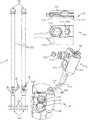
- FIG. 1is an embodiment of an inflatable indwelling medical device comprising a retention balloon and a valve system B for preventing over-inflation of the retention balloon.
- FIG. 2 Ais an embodiment of a valve system B comprising an umbrella valve.
- FIG. 2 Bis an embodiment of an umbrella valve for use in a valve system provided herein.
- FIG. 3 Ais an embodiment of a valve system B comprising a spring loaded ball valve.
- FIG. 3 Bis an embodiment of a spring loaded ball valve for use in a valve system provided herein.
- FIG. 4 Ais an embodiment of a valve system B comprising a spring loaded poppet valve.
- FIG. 4 Bis an embodiment of a spring loaded poppet valve for use in a valve system provided herein.
- FIG. 5is an embodiment of a rupturing disc for use in a valve system provided herein.
- FIG. 6is a plot of balloon diameter versus the inflated volume of the balloon when the balloon is inflated with air in a system having or not having a pressure relief valve.
- FIG. 7is a plot of balloon pressure versus the inflated volume of the balloon when the balloon is inflated with air in a system having or not having a pressure relief valve.
- FIG. 8is a plot of balloon diameter versus the inflated volume of the balloon when the balloon is inflated with water in a system having or not having a pressure relief valve.
- FIG. 9is a plot of balloon pressure versus the inflated volume of the balloon when the balloon is inflated with water in a system having or not having a pressure relief valve.
- FIG. 10is a plot of balloon pressure versus the inflated volume of the balloon when the balloon is inflated with water in systems having or not having a pressure relief valve.
- One systemcomprised a pressure relief valve having a 60 mm Hg cracking pressure, and another system comprised a pressure relief valve having a 75 mm Hg cracking pressure.
- a distally placed retention balloonmay be inserted into the body in a deflated condition and positioned inside the rectal cavity. It is important that the retention balloon is not over-inflated and does not exceed pre-determined pressures in the patient. Complications of over-inflation include bruising, ulceration, tissue necrosis and infection in the patient.
- Challenges for controlling and maintaining proper and adequate pressure in the retention ballooninclude a limited footprint in the medical devices to incorporate pressure relief and maintenance systems, including safety concerns for patients, adequate pressure control and prevention of pressure spikes if incorporated into the inlet or inflation lumen of the retention balloon, and the low pressure maintained in the retention balloon, presenting a technical challenge in maintaining pressures in the range of 10 mm Hg to 100 mm Hg (approximately 0.2 psi to 2 psi).
- the present inventionprovides valves and valve systems, including pressure relief valves, for the prevention of over-inflation of inflatable indwelling medical devices, including fecal management systems.
- the pressure relief valveis incorporated into the outlet or returning lumen of the retention balloon system in order to address the challenges presented in low pressure maintenance and control.
- the pressure relief valves described hereinmay be mechanical, with a small footprint or dimension, allowing operation within the low pressure maintenance systems used in these indwelling medical devices.
- Additional indwelling medical devicesinclude catheter balloon dilatations which are widely used to dilate areas of narrowing in blood vessels, ureters, and in the gastrointestinal tract, such as urinary catheters, airway catheters, tracheal catheters, drainage devices, patency devices, devices for the administration of therapeutics and drugs, feeding tubes, and the like.
- an embodiment of an inflatable indwelling medical device Acomprising a valve system B and an elongated flexible tubular element 102 having a distal end 104 for positioning the device A into a body cavity of a patient.
- the proximal end 106 of tubular element 102may connect to a receptacle to collect waste from the patient that drains through an interior of the tubular element 102 when the device A is positioned within the patient.
- Affixed to the exterior surface of the distal end 104 of the tubular element 102is an inflatable retention balloon 108 , shown in its inflated state, that serves to anchor the distal end 104 of the device A in the body cavity.
- Retention balloon 108is connected to a valve system B through a supply fluid path provided by a supply lumen 110 and return fluid path provided by a return lumen 122 .
- Valve system Bis designed for limiting fluid pressure within the retention balloon 108 during inflation and when the retention balloon 108 is held within the body cavity.
- the body 112 of valve system Bcomprises an inlet port 116 for receiving a connector associated with a source of fluid for inflation of the retention balloon 108 , and an outlet port 114 connected to the supply fluid path, the inlet port 116 and outlet port 114 connected via a first passage within body 112 .
- Valve system Bfurther comprises a second passage connected to the return fluid path, the second passage composing a fill indicator 118 and pressure relief valve 120 .
- the second passageis connected to the retention balloon 108 via the return fluid path such that the second passage receives the pressure from retention balloon 108 . If the pressure within the retention balloon 108 exceeds a first pressure, for example, during inflation, the fill indicator 118 provides a notification, such as a visual and/or audible notification, to the practitioner filling the retention balloon 108 to remove excess fluid from the retention balloon 108 via the inflation port 116 . If the pressure within the retention balloon 108 exceeds a second pressure, the pressure relief valve 120 will open, releasing excess fluid from the retention balloon 108 through the second passage of the valve system.
- a first pressurefor example, during inflation
- the fill indicator 118provides a notification, such as a visual and/or audible notification, to the practitioner filling the retention balloon 108 to remove excess fluid from the retention balloon 108 via the inflation port 116 .
- the second pressuremay be the same or greater than the first pressure.
- the first pressureis an optimal pressure of the retention balloon 108 , so that the fill indicator 118 notifies a practitioner filling the retention balloon 108 that the optimal pressure has been met and to halt inflation. If the fill indicator 118 is a mechanical element, a first state of the fill indicator 118 may indicate under-inflation whereas the second state may indicate both optimal inflation and over-inflation.
- the pressure relief valve 120 and the fill indicator 118are situated in the second passage and the inflation port 116 is within the first passage to the retention balloon 108 .
- the fill indicator 118 shown in FIG. 1comprises a dome positioned over the second fluid passage. When the first pressure is reached, the dome expands outward to provide a visual indication that the first pressure has been reached.
- fill indicator 118may alternatively or additionally provide a pneumatic or electronic indication of when the first pressure is reached, for example, via a solenoid valve, pneumatic valve, light emitting diode (LED) or other light, audible sound, wireless beeping, or the like.
- the pressure relief valve 120 shown in FIG. 1is an umbrella valve situated on a valve seat 124 .
- a valve systemmay comprise a spring loaded ball valve, a spring loaded poppet valve, a rupturing disc, or a combination thereof.
- the pressure relief valveis selected to have a cracking pressure (i.e. minimum pressure required to open the valve) within the valve system that corresponds to a maximum pressure of the retention balloon 108 to which it is connected.
- valve system B shown in FIG. 1is useful for limiting the pressure of retention balloon 108 during inflation or when device A is maintained within the body cavity of the patient.
- Methods of using valve system B for this purposeinclude: (a) providing an inflatable indwelling medical device A as generally shown in FIG.
- the inflation port 116comprises a Luer fitting that connects to a Luer lock syringe that serves as a source of fluid.
- engagement of the source of inflation fluid to the inflation port 116allows access of fluid to a Leur check valve, and when a certain pressure is met, allows for the opening of the Leur check valve.
- engagement of the source of inflation fluid to the inflation port 116opens a seal, allowing for access to a Leur check valve.
- the Luer check valvemay comprise a body, stem and plug. In some cases, the stem comprises an elastic rubber.
- the Luer check valvemay be normally closed such that when the stem of the valve is compressed by the Luer tip of the source of inflation fluid (i.e., syringe), it opens up a fluid path to allow for passage of the fluid into the first passage of the valve system B.
- the source of inflation fluidi.e., syringe
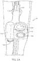
- valve system Bcomprising an umbrella valve 132 as a pressure relief valve is shown in FIG. 2 A .
- valve system Bcomprises first and second passages enclosed within a body 112 .
- a fill indicator 118situated within the second passage is a fill indicator 118 and an umbrella valve 132 seated on a valve seat 134 .
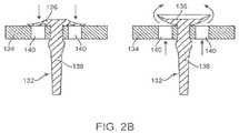
- a detailed view of umbrella valve 132 and valve seat 134is shown in FIG. 2 B .
- Umbrella valve 132comprises a sealing disk 136 which flattens against the valve seat 134 with a certain sealing force, and a stem 138 .
- the sealing disk 136may have elastic material properties and convex shape to create the sealing force, while the stem 138 is used to hold the umbrella valve 132 in place so as to avoid the need for additional components such as a spring or positioner.
- the valve seat 134comprises vents 140 . When a force exerted on the sealing disk 136 through vents 140 is sufficient to lift the convex diaphragm from the seat 134 , the umbrella valve 132 allows for flow to occur in a forward direction ( FIG. 2 B , right panel), while preventing back flow in the opposite direction ( FIG. 2 B , left panel).
- the umbrella valve 132is orientated such that the forward direction is the direction that fluid takes as it leaves the body 112 from the second passage, through umbrella valve 132 .
- Umbrella valve 132may be selected such that the force necessary to open the umbrella valve 132 corresponds to a predetermined pressure of retention balloon 108 that is conferred to the second passage of the valve system B.
- the predetermined pressuremay correspond to the cracking pressure of the umbrella valve 132 , which may be from about 30 mm Hg to about 90 mm Hg, or from about 50 mm Hg to about 70 mm Hg.
- FIG. 3 AAn embodiment of a valve system B is shown in FIG. 3 A , comprising a spring loaded ball valve 142 that releases fluid when a predetermined pressure is exceeded, and then closes when the pressure drops below the predetermined level.
- FIG. 3 BA detailed view of the spring loaded ball valve is shown in FIG. 3 B .
- the spring loaded ball valve 142comprises a ball 144 positioned against a spring 146 , such that when the pressure of fluid within the balloon 108 exceeds a predetermined level, the fluid exerts a force on the ball 144 that compresses spring 146 to allow the fluid to move in a forward direction.
- a spring loaded ball valve 142may be selected such that the force necessary to compress ball 144 corresponds to a predetermined pressure of balloon 108 that is recognized at the valve system B.
- the predetermined pressuremay correspond to the cracking pressure of the spring loaded ball valve 142 , which may be from about 30 mm Hg to about 90 mm Hg, or from about 50 mm Hg to about 70 mm Hg. In some embodiments, the cracking pressure is about 60 mm Hg.
- FIG. 4 AAn embodiment of a valve system B comprising a spring loaded poppet valve 148 is shown in FIG. 4 A .
- the spring loaded poppet valve 148( FIG. 4 B ) is positioned within the valve system B such that the spring of the poppet valve 148 and the pressure from within the second passage apply opposing forces on the spring loaded poppet valve 148 .
- the force from the second passageexerts a greater force than the spring force (i.e. the cracking pressure)
- the poppetmoves away from a valve seat, allowing thud to pass through an outlet port of the spring loaded poppet valve 148 .
- the valvecloses.
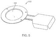
- a rupturing disc 150Another type of pressure relief valve useful in a valve system B provided herein is a rupturing disc 150 , as shown in FIG. 5 .
- the rupturing disccomprises a one-time-use membrane 152 that ruptures at a predetermined differential pressure.
- a valve system provided hereincomprises a first pressure relief valve and as a backup device, a rupturing disc. For instance, if the pressure increases and the first pressure relief valve fails to operate or does not relieve enough pressure fast enough, the rupturing disc will burst.
- valve systems provided hereinhave a first and a second passage that are non-interfering or non-interacting. This is distinctively different from previously described valve systems, such as those described in US 2015/0051542.
- the first passagecan continue to be filled in the present disclosure if the cracking pressure is set as such.
- the systems hereinallow for the cracking pressure to be set above the pre-determined filled pressure, while the valve system described in US 2015/0051542 would stop the flow from the first passage as soon as the pressure in the second passage reaches the pre-determined filled pressure.
- Such a design in the present disclosurehas an advantage in a clinical use not achievable through the valve system in US 2015/0051542.
- valve systems with restricted flexibility of the operating windowallow the fill pressure to be varied due to patients.
- the rectal pressure in an obese patientmay be higher than the rectal pressure of a patent with an average weight and rectum size.
- the fill pressure in an obese patient populationmay need to be adjusted above the optimum fill pressure in order to allow the balloon to be inflated and thus anchored inside the rectum.
- the present described systemsallow for the balloon to be filled at a pressure range above the optimum fill pressure.
- the optional fill indicator in the deviceoffers a cue or signal to the proper fill volume.
- FIG. 10shows that there is a range of from 40 ml to 50 ml filled volume to allow for balloon inflation when a 60-mm-Hg pressure relief valve is used in one embodiment of the present invention.
- FIG. 10also shows dial in this embodiment, there is a range of from 40 ml to 60 ml filled volume to allow for balloon inflation when a 75-mm-Hg pressure relief valve is used.
- Such a wider operating range of the present systemsallows a clinician to inflate rectal balloon in most patients without the restrictions necessary using the systems of US 2015/0051542, where the operating range of the filled volume on a specific patient was very narrow.
- the use of the optional fill indicatoradds another safety feature to allow clinician to judge the onset of optimum filled volume (thus balloon pressure).
- valve systemscomprising a pressure relief valve having an open configuration and a closed configuration to permit or deny, respectively, the passage of fluid to and/or from an inflatable portion of an inflatable indwelling medical device.
- a pressure relief valveis located within a second passage of the valve system so that any pressure spikes that may occur during inflation via the first passage do not prematurely open the valve.
- the pressure relief valveis selected in part to have a limited footprint in the valve system of an inflatable indwelling medical device.
- a small footprintminimizes the chance of developing a pressure sore when a patient lies over the valve system or rubs against it such as may be the case with a fecal catheter.
- Foley catheter and air way catheterwhich are intimately close to sensitive areas of the body.
- the height of a valve system comprising a pressure relief valveis less than or about 50 mm, 40 mm, 30 mm, 20 mm, 15 mm or 10 mm. In some embodiments, the height of a pressure relief valve is less than or about 50 mm, 40 mm, 30 mm, 20 mm, 15 mm or 10 mm.
- the height of a valve systemis less than about 20 mm. In some cases, the height of a pressure relief valve is less than about 20 mm. In some cases, the height of a pressure relief valve is less than about 15 mm. In some cases, the height of a pressure relief valve is less than about 10 mm.
- the pressure relief valveis also selected for the cracking pressure, or the minimum pressure within the second passage to force the valve open.
- the pressure relief valvemay be selected so that its cracking pressure corresponds to the pressure limitations required for the particular inflatable indwelling medical device.
- the cracking pressureis met during inflation of the inflatable portion of the device.
- the cracking pressureis met after balloon inflation, for example, the cracking pressure is achieved by pressure changes within the inflatable portion which may be caused by pressure changes within a patient's body, including pressure changes caused by coughing, sneezing, peristalsis, movement, sitting, and crying.
- a c nicking pressure of a valve in a system described hereinis from about 10 mm Hg to about 120 mm Hg, about 10 mm Hg to about 100 mm Hg, about 10 mm Hg to about 90 mm Hg, about 10 mm Hg to about 80 mm Hg, about 10 mm Hg to about 70 mm Hg, about 20 mm Hg to about 90 mm Hg, about 20 mm Hg to about 80 mm Hg, about 30 mm Hg to about 90 mm Hg, about 30 mm Hg to about 80 mm Hg, about 40 mm Hg to about 90 mm Hg, about 40 mm Hg to about 80 mm Hg, about 50 mm Hg to about 80 mm Hg, or about 50 mm Hg to about 70 mm Hg.
- the cracking pressuremay be from about 50 mm Hg to about 70 mm Hg. In some cases, the cracking pressure of a valve is about within a system described herein is about 30 mm Hg to about 90 mm Hg.
- the tolerancemay be about ⁇ 5%, 6%, 7%, 8%, 9%, 10%, 11%, 12%, 13%, 14%, 15%, 16%, 17%, 18%, 19% or 20%. In some cases, the tolerance is about a ⁇ 15%.
- the cracking pressuremay be from about 50 mm Hg to about 70 mm Hg with a tolerance of about ⁇ 15%.
- the cracking pressure of a valveis about 30, 35, 40, 45, 50, 55, 60, 65, 70, 75, 80, 85 or 90 mm Hg with a tolerance of ⁇ 10 mm Hg or preferably ⁇ 5 mm Hg.
- a rate of fluid flow within a lumen of a valve systemis dependent on the cracking pressure of a valve of the system.
- Pressure relief valves useful in the systems provided hereininclude blow-off valves or cracking pressure check valves, wherein the valves open when a set pressure is reached. For example, once a predetermined pressure is reached within a valve system, the valve opens to release the pressure, preventing over-inflation of an inflatable portion of an inflatable indwelling medical device.
- Non-limiting examples of pressure relief valves useful in the valve systems described hereininclude umbrella valves, duckbill valves, split valves, metal spring valves, film valves, and Belleville valves.
- the valveis flanged.
- the valveis sleeved.
- the valveis a combination valve, for example, a valve comprising two or more valves in one single component. In some cases, a combination valve comprises a duckbill and an umbrella.
- the pressure relief valvemay be a one-way valve that creates unidirectional flow in a device.
- the pressure relief valvemay comprise elastomeric sealing elements that allow forward flow and prevent backflow.
- one-way valvesinclude an umbrella valve, spring loaded ball valve, spring loaded poppet valve and rupturing disc.
- the pressure relief valveis a two-way valve that allows for the passage of fluid in two directions when open.
- Pressure relief valvesmay be made of any material suitable for integration within an indwelling medical device.
- Materialsinclude, without limitation, silicone, elastomers, fluoropolymers, synthetic or natural rubbers, polyethylene, polypropylene, nylon, acetal, PVDF, ABS, and hydrocarbon-resistant fluorosilicone rubber.
- Elastomeric materialsare often characterized with a hardness of less than Shore A 75, less than Shore A 60, or preferably, less than Shore A 50.
- a pressure relief valveis not ferromagnetic. In some cases, ferromagnetic valves are not used to allow a patient using a valve system within an indwelling medical device to be scanned by magnetic resonance imaging.
- a pressure relief valveis mechanically held within a valve system, for example, the valve is positioned on a seat.
- a pressure relief valveis glued or otherwise held within a valve system.
- a pressure relief valveis welded to another component of a valve system.
- a pressure relief valveis an umbrella valve
- the umbrella valvecomprises a diaphragm shaped scaling disk, i.e., umbrella shape, and a stem.
- the convex diaphragmflattens out against the valve seat and absorbs a certain amount of seat irregularities and creates a certain sealing force.
- the umbrella valvewill allow forward flow once the head pressure creates enough force to lift the convex diaphragm from the seat and so it will allow flow at a predetermined pressure in one way and prevent back flow immediately in the opposite way.
- the opening pressureis variable by varying seat thickness.
- the stem heightis from about 1 mm to about 20 mm, or about 1, 2, 3, 4, 5, 6, 7, 8, 9, 10, 11, 12, 13, 14, 15, 16, 17, 18, 19 or 20 mm.
- the valve seat heightis at least about 1, 2, 3, 4, or 5 mm.
- the sealing diskhas a diameter from about 5 mm to about 20 mm.
- the cracking pressure of an umbrella valvemay vary according to the configuration of the valve and/or the valve seat.
- the height of a valve seatcontributes to the cracking pressure of a valve residing in the seat.
- the size of a vent in the valve seatcontributes to a cracking pressure of the valve. For instance, for a valve requiring a high flow rate, the flow vents in the seat are larger and for a valve requiring a low flow rate, the flow vents in the seat are smaller.
- the flow vents in the seatare smaller, the seat is taller and the umbrella is more substantial such that the edge of the umbrella would be more difficult to lift up.
- a valve seatis selected for a valve system herein having a thickness of about 0.5 mm to about 5 mm, about 0.5 mm to about 4 mm, about 0.5 mm to about 3 mm, about 0.5 mm to about 2 mm, about 0.5 mm to about 1 mm, about 1 mm to about 5 mm, about 1 mm to about 4 mm, about 1 mm to about 3 mm, or about 1 mm to about 2 mm.
- a valve seathas a seat height of about 0.5, 0.6, 0.7, 0.8, 0.9, 1, 1.1, 1.2, 1.3, 1.4, 1.5, 1.6, 1.7, 1.8, 1.9, 2, or 2.5 mm.
- the cracking pressure of the umbrella valvemay be from about 30 mm Hg to about 90 mm Hg, or from about 50 mm Hg to about 70 mm Hg.
- an umbrella valveis a Belleville valve comprising a stem that is held in place in a seat by a retainer Hus retainer could be a separate component or an integral part of the device in which it is integrated such as a cap or lid just above the umbrella valve.
- a pressure relief valveis a duckbill valve.
- the duckbill valvecomprises elastomeric lips in the shape of a duckbill which prevent backflow and allow forward flow.
- Duckbill valvesmay not require integration with a seat surface to form a seal. Instead, the sealing function of the valve is an integral component of the valve.
- a pressure relief valveis a split valve.
- a split valvecomprises a distal slit partially across a transverse valve section, wherein the slit is configured to be open by receipt of a force pushed against one side of the valve, and then closed when the force is removed.
- the forceis the pressure exerted by fluid within the valve system during inflation.
- the forceis the pressure within the valve system caused by application of another external force on an inflatable portion of an inflatable indwelling medical device.
- the valve sealcomprises two opposing halves, either molded separately or formed from an integrally molded valve seal that is bisected and then fused together to form a weak bond that is easily broken during splitting.
- a pressure relief valveis a cartridge type in which a rigid seating is incorporated.
- a cartridge type valvetypically comprises a body. O-ring, poppet, cartridge and a metal spring.
- a cartridge type valvecomprises a body, O-ring, and an umbrella valve.
- a cartridge type valvecomprises a body, O-ring, and a duckbill valve.
- a pressure relief valveis a film valve or cracking pressure check valve.
- a pressure relief valveis an umbrella valve.
- a cracking pressure check valvecomprises multiple components that are integrated into a single, molded valve. By changing the tension on the valve stem, a different cracking pressure can be achieved. The flow rate is controlled by varying the size of the valve orifices.
- a pressure relief valveis a spring loaded ball valve that releases fluid when its cracking pressure is reached, and then closes when the pressure drops below the cracking pressure.
- the spring loaded ball valvemay comprise a ball positioned against a spring such that when the cracking pressure is reached, the pressure exerts a force on the ball that compresses the spring to allow the fluid to move in a forward direction.
- the cracking pressure of the spring loaded ball valvemay be from about 30 mm Hg to about 90 mm Hg, or from about 50 mm Hg to about 70 mm Hg.
- a pressure relief valveis a spring loaded poppet valve positioned within the valve system such that the spring of the poppet valve and the pressure from within the second passage apply opposing forces on the spring loaded poppet valve.
- the force from the second passageexerts a greater force than the spring force (i.e. the cracking pressure)
- the poppetmoves away from a valve seat, allowing fluid to pass through an outlet port of the spring loaded poppet valve.
- the cracking pressure of the spring loaded poppet valvemay be from about 30 mm Hg to about 90 mm Hg, or from about 50 mm Hg to about 70 mm Hg.
- a valve systemcomprises, or is operably connected to, a fill indicator that indicates to a clinician and/or user once an inflatable portion has reached and/or exceeded an optimal fill volume; an optimal fill pressure; or either an optimal fill volume or optimal fill pressure, whichever is reached first.
- the fill indicatormay reside within the body of the valve system or be a separate component from the body. If the system comprises a return fluid path and an enclosure (e.g., return lumen), the fill indicator may reside within the enclosure. In some instances, the fill indicator resides within the body of a valve system in fluid communication with a return fluid path.
- a fill indicatoris a visual and/or audible indicator that provides notification once an inflatable portion has reached or surpassed an optimal fill volume and/or pressure.
- a fill indicatoris a mechanical element configured to alternate between a first physical state and a second physical state depending on a pressure within the second passage corresponding to the pressure within the inflatable portion.
- the mechanical elementis in a first physical state when the optimal fill volume and/or pressure within the inflation portion has not been met, and in a second physical state when the optimal fill volume and/or pressure has been met or exceeded.
- the mechanical elementis in a first physical state when the inflatable portion is under-inflated.
- the mechanical elementis in a second physical state when the inflatable portion is over-inflated.
- the mechanical elementis in a second physical state when the inflatable portion is filled to an optimal fill volume and/or pressure.
- a valve systemcomprises both a fill indicator and a pressure relief valve, such that the fill indicator indicates when a first pressure is achieved and the pressure relief valve prevents over-inflation when a second pressure is achieved.
- the pressure relief valveprevents over-inflation by opening once the second pressure is reached.
- the second pressureis a predetermined fill pressure corresponding to the cracking pressure of the pressure relief valve.
- the second pressureis a maximum fill pressure.
- the first pressureis an optimal fill pressure.
- the pressure relief valveprevents over-inflation by not allowing the inflatable portion to reach a pressure higher than the first pressure.
- the pressure relief valveprevents over-inflation by not allowing the inflatable portion to reach a pressure higher than a desirable pressure, which is higher than the optimal fill pressure, and is defined by the pressure that could cause significant tissue damage over an extended period of tissue contact. In some cases, the pressure relief valve prevents over-inflation by not allowing the inflatable portion to reach a pressure that is 5%, 10%, 15%, 20%, 25%, 30%, 50%, or 100% higher than the first pressure. In some cases, the first pressure is different from the second pressure. In some cases, the first pressure is lower than the second pressure. In some cases, the first and second pressures differ by less than about 100%, 75%, 50%, 40%, 30%, 20%, 15%, 10%, 5%, or 1%.
- the medical devicecomprises a rectal catheter.
- the medical devicecomprises a urinary catheter in some cases, the medical device comprises an airway catheter.
- the medical devicecomprises a tracheal catheter.
- the inflatable portionis a retention balloon configured to retain a distal end of device within a body cavity.
- an inflatable portione.g., retention balloon, has a fill capacity less than about 70 ml, 60 ml, 50 ml, 45 ml, 40 ml, 35 ml, 30 ml, 25 ml, 20 ml, 15 ml, 10 ml or less.
- the inflatable portionis a retention balloon of a fecal management system comprising a rectal catheter and has a fill capacity from about 25 ml, to about 60 ml, from about 25 ml to about 50 ml, from about 35 ml to about 45 ml, from about 30 ml to about 60 ml, from about 30 ml to about 50 ml, from about 30 ml to about 45 ml, from about 35 ml to about, 55 ml, from about 35 ml to about 50 ml, from about 35 ml to about 45 ml, or from about 40 ml to about 50 ml.
- the inflatable portioninflates with no more than about 55, 54, 53, 52, 51, 50, 49, 48, 47, 46, 45, 44, 43, 42, 41 or 40 mL of liquid. In some cases, the inflatable portion inflates with no more than about 45 mL of liquid. In such cases where the inflatable portion is inflated with no more than 45 mL of liquid, the pressure within the inflatable portion may be about 50 mm Hg ⁇ 5 mm Hg when the pressure relief valve is triggered to open. In some cases, the inflatable portion inflates with no more than about 50 mL of liquid.
- the pressure within the inflatable portionmay be about 50 mm Hg ⁇ 5 mm Hg when the pressure relief valve is triggered to open.
- the pressure at which the pressure relief valve opens, the cracking pressuremay be tailored to each patient.
- the range of cracking pressures for a pressure relief valvemay be from about 50 mm Hg to about 70 mm Hg. This may allow for variation between patients and pressure relief valves.
- the inflatable portionis a retention balloon of a urinary catheter that has a fill capacity from about 5 ml to about 20 ml, from about 5 mi to about 15 ml, from about 8 ml to about 12 ml.
- the inflatable portioncomprises a foam filling.
- the foamwill self-inflate the inflatable portion. This enables the inflatable portion to return to its original size following a pressure change. For example, the pressure changes with a contraction and expansion cycle within the body, such as occurs during and following a cough.
- Suitable foamsinclude polyurethane foams and memory foams.
- a valve system described hereinallows for an inflatable portion of an inflatable medical device to be filled with fluid to an optimal volume and/or pressure to prevent under-inflation or over-inflation of the inflatable portion.
- the fluidis air.
- the fluidis a liquid, for example, water or saline solution.
- an optimal fill pressureis a pressure between a minimum pressure and a maximum pressure within an inflatable portion of an inflatable indwelling medical device.
- the minimum pressurecorresponds to a minimum pressure necessary to retain the inflatable portion within a body cavity.
- the maximum pressureis the highest amount of pressure an inflatable portion can handle before the inflatable portion is over-inflated. Over-inflation may result in abnormal blood perfusion in the soft tissue contacted by the inflatable portion, and/or pressure necrosis of the soft tissue.
- an optimal fill pressureis from about 20 mm Hg to about 90 mm Hg, from about 20 mm Hg to about 80 mm Hg, from about 20 mm Hg to about 70 mm Hg, from about 20 mm Hg to about 60 mm Hg, from about 20 mm Hg to about 50 mm Hg, from about 30 mm Hg to about 90 mm Hg, from about 30 mm Hg to about 80 mm Hg, from about 30 mm Hg to about 70 mm Hg, or from about 30 mm Hg to about 50 mm Hg.
- a minimum fill pressureis from about 20 mm Hg to about 50 mm Hg, for example, about 20, 25, 30, 35, 40, 45 or 50 mm Hg.
- a maximum fill pressureis from about 40 to about 90 mm Hg, for example, about 40, 45, 50, 55, 60, 65, 70, 75, 80, 85, or 90 mm Hg.
- a maximum pressurecorresponds to the cracking pressure of a valve used within the system.
- a maximum pressurecorresponds to a pressure about 5%, 10%, 15%, 20%, 30%, 40%, or 50% greater than the cracking pressure of a valve used within the system.
- a maximum pressurecorresponds to the cracking pressure of a valve used within the system.
- a preferred operation pressurecorresponds to a pressure about 5%, 10%, 15%, 20%, 30%, 40%, or 50% lower than the cracking pressure of a pressure relief valve used within the system.
- an optimal fill volumeis a volume between a minimum fill volume and a maximum fill volume.
- the minimum fill volumeis the minimum volume of an inflatable portion necessary to retain the inflatable portion within a cavity of a patient.
- the maximum fill volumeis the maximum volume an inflatable portion can contain at a maximum pressure.
- the optimal fill volumeis patient dependent, for example, if the cavity of the patient is small or is under pressure (e.g., in obese patients), the optimal fill volume is lower than that of a patient with a larger cavity or a cavity that is not under said pressure.
- the optimal fill volume fora retention balloon of an indwelling medical deviceis dependent on the characteristics of the body cavity, for example, the optimal fill volume for a urinary catheter system is smaller than that of a fecal catheter system.
- minimum fill volumes for inflatable portions of rectal catheter systemsinclude 5 ml, 10 ml, 20 ml, 25 ml, 26 ml, 27 ml, 28 ml, 29 ml, 30 ml, 31 ml, 32 ml, 33 ml, 34 ml, 35 ml, 40 ml, 45 ml, 50 ml, and 60 ml.
- Non-limiting examples of maximum fill volumes for inflatable portions of rectal catheter systemsinclude 25 ml, 30 ml, 35 ml, 36 ml, 37 ml, 38 ml, 39 ml, 40 ml, 41 ml, 42 ml, 43 ml, 44 ml, 45 ml, 50 ml, 75 ml, and 100 ml.
- an optimal fill volume for an inflatable portion of a rectal catheter system comprising a valve system described hereinis from about 20 ml to about 50 ml, from about 30 ml to about 50 ml, from about 35 ml to about 45 ml, from about 30 ml to about 45 ml, and from about 35 ml to about 45 ml.
- a pressure relief valveis configured to prevent over-inflation of an inflatable portion of an inflatable indwelling medical device past a predetermined fill volume.
- the predetermined fill volumeis the maximum fill volume or about 100%, 75%, 50%, 30%, 25%, 20%, 15%, 10%, 5% or 1% less than the maximum fill volume.
- the predetermined fill volumeis the optimal fill volume or about 5%, 10%, 15%, 20%, 25%, 50%, 75% greater than the optimal fill volume.
- a valve of a valve systemprevents the over-inflation of the inflatable portion past a predetermined fill pressure.
- the predetermined fill pressureis the maximum fill pressure or about 100%, 75%, 50%, 30%, 25%, 20%, 15%, 10%, 5% or 1% less than the maximum fill pressure. In other cases, the predetermined fill pressure is the optimal fill pressure or about 5%, 10%, 15%, 20%, 25%, 50%, 75% greater than the optimal fill pressure.
- a pressure relief valveprevents the inflation of the inflatable portion past either a predetermined fill volume or a predetermined fill pressure, whichever occurs first. As one example, the pressure relief valve prevents the over-inflation of the inflatable portion once it reaches a predetermined fill pressure, even if the predetermined fill volume has not been met. This may occur in catheter devices, wherein the size of the body cavity (e.g., rectal cavity, bladder) is smaller or under more pressure in some patients than in others.
- an indwelling medical deviceis a fecal catheter or a urinary catheter.
- a cathetercomprises an inflation port, a balloon, a catheter tube, a drainable bag, a sample port, an irrigation port, etc.
- the balloonis made from elastomers such as a silicone, natural rubber, or elastomers.
- the catheteris made from silicone, natural rubber, or elastomers.
- the inflation portcomprises a Luer access check valve to allow for balloon inflation.
- Balloon materialsinclude, without limitation, plastic, silicone, elastomers, fluoropolymers, synthetic or natural rubbers, polyethylene, polypropylene, nylon, acetal, PVDF, ABS, and hydrocarbon-resistant fluorosilicone rubber.
- An inflatable indwelling medical devicemay comprise: (a) an apparatus composing a fluid inlet port and a fluid outlet port connected by a first passage, and a second passage, wherein the first passage and the second passage are not connected within the apparatus; (b) a retention balloon; (c) a supply fluid path connecting the first passage of the apparatus at the fluid outlet port to the retention balloon; (d) a return fluid path connecting the second passage to the retention balloon; wherein the second passage comprises a pressure relief valve that opens at a predetermined pressure.
- the predetermined pressureis from about 30 mm Hg to about 90 mm Hg, or from about 50 mm Hg to about 70 mm Hg.
- the inflatable indwelling medical devicefurther comprises a fill indicator that provides notification when the retention balloon is filled to or above an optimal fill level.
- the fill indicatormay be positioned at the second passage.
- the retention balloonmay be positioned at the distal end of a catheter for insertion into a body cavity of a patient.
- the proximal end of the cathetermay be configured for coupling to a collection bag.
- the inflatable indwelling medical deviceis a fecal management system (FMS) and the catheter is a rectal catheter.
- the inflatable indwelling medical deviceis a urinary management system and the catheter is a urinary catheter.
- the retention balloonis configured for insertion within the body cavity so that when the balloon is inflated to a minimum volume and/or pressure, the inflated balloon maintains the distal end of the catheter within the body cavity, allowing for body waste to flow from the body cavity, through the drain channel of the catheter, and into the collection bag.
- Methods of preventing over-inflation of a retention balloon of the indwelling medical devicemay comprise: (a) providing an indwelling medical device comprising (i) a tubular element defining a drain passage for effluent from a body cavity; (ii) a retention balloon located at a distal end of the tubular element for insertion into the body cavity; (iii) a housing comprising a pressure relief valve and an inflation port; (iv) an inflation lumen providing a First fluid path between the retention balloon and the housing, wherein the retention balloon is located at a distal end of the inflation lumen and the inflation port is located at a proximal end of the inflation lumen; and (v) a return lumen providing a second fluid path between the retention balloon and the housing, wherein the retention balloon is located at a distal end of the return lumen and the housing is located a proximal end of the return lumen, and wherein the valve is in fluid communication with the second fluid path; (b) inserting the retention balloon
- a valve systemis integrated within a fecal management system (FMS) to prevent over-inflation of the retention balloon of the FMS.
- the FMShas the configuration generally shown in FIG. 1 .
- the FMScomprises a retention balloon 108 that is configured for placement within the rectal cavity to retain a catheter having a drain channel 102 for the diversion of waste fluids from the rectal cavity of a patient to a fluid collection bag.
- the FMS of this examplefurther comprises an auxiliary lumen to provide irrigation to the rectal cavity.
- the valve system Bcomposes first passage connecting an inflation port 116 to an inflation lumen 110 , which is further connected to the retention balloon 108 .
- the inflation port 116comprises an opening to allow for the passage of fluid between a syringe and the retention balloon 108 via a first fluid pathway comprising the first passage within the valve system B, and a supply fluid path within inflation lumen 110 .
- the valve system Bfurther comprises a second passage.
- a second fluid pathwayconnects the retention balloon 108 , a return lumen 122 , and the second passage. In this example, the second passage and the first passage do not interact.
- the second passagecomprises a fill indicator that provides a notification, such as a visual notification, when an optimal pressure within the retention balloon 108 has been met.
- the second passagefurther comprises an umbrella valve having open and closed configurations. The umbrella valve opens when the pressure within the system reaches the cracking pressure of the valve, releasing pressure from within the system. The cracking pressure was selected to correspond to an over-inflation pressure within the retention balloon 108 .
- a FMS as described in Example 1was equipped with a pressure relief valve set at 60 mm Hg.
- a cartridge valve having an outside diameter of 10 mm with a 7 mm umbrella valve made from a Shore A 50 siliconewas glued into the valve system.
- the height of the cartridge valvewas 6 mm.
- the cartridge valvewas made from ABS.
- the retention balloons of the FMS with and without the pressure relief valveswere filled with air from 5 cc up to 100 cc to observe the balloon diameter and the filled balloon pressure, respectively.
- the datawas plotted as shown in FIGS. 6 - 9 .
- the balloon diameterexpands linearly with the filled volume in the control device lacking the pressure relief valve.
- the balloon diameterexpands linearly with the filled volume until it reaches at around 58.3 mm diameter, it then stays at around 58.3 mm upon further increase in fill volume.
- the measurement of the balloon pressure versus the filled volume with airis shown in FIG. 7 .
- the balloon pressurestayed near zero initially because the balloon was molded with a set diameter of around 51 mm.
- the balloon pressurebegan to rise exponentially at around 35 ml filled volume, and continued to rise to about 93 mm Hg in the control system.
- the balloon pressurefollowed about the same trend as the control device at a filled volume from 0 ml to around 50 ml. After 50 ml, the balloon pressure stayed at around 60 mm Hg because of the control by the pressure relief valve.
- the same testwas repeated with the water instead of air.
- the plots of FIG. 8 and FIG. 9show that similar trends were observed as FIG. 6 and FIG. 4 , respectively.
- a FMS as described in Example 1was equipped with a pressure relief valve set at 60 mm Hg (as in Example 2), 75 mm Hg, or no pressure relief valve (control device).
- the cartridge valvehad an outside diameter of 10 mm with a 7 mm umbrella valve.
- the height of the cartridgewas 6 mm.
- the cartridge valvewas made from ABS. The cartridge valve was glued into the valve system of the FMS of Example 1.
- the balloons of each systemwere filled with water from 5 cc up to 100 cc to observe the balloon pressure among three systems, respectively.
- the datawas plotted as shown in FIG. 10 .
- the balloon pressurestayed near zero initially since the balloon was molded with a set diameter of around 51 mm.
- the balloon pressurebegan to rise exponentially at around 35 ml filled volume, and then continue to rise to about 93 mm Hg in the control system.
- the balloon pressurefollowed about the same trend as the control device at a filled volume from 0 ml to around 50 ml. After 50 ml, the balloon pressure stayed at around 60 mm Hg.
- An FMS as described in Example 1was equipped with a spring loaded ball valve having a critical relief pressure set at 75 mm Hg.
- the spring loaded ball valvewas purchased from Lee Co. (Westbrook, Conn., USA).
- the pressure relief valvehas a diameter of 5.46 mm and a length of 7.3 mm.
- the ball valvewas built from ceramic with a stainless steel housing, a stainless steel cage, and stainless steel spring.
- the critical relief pressurewas controlled by the selection of the spring.
- the spring loaded ball valvewas glued into the fill indicator of the FMS (Example 1), and is shown in FIGS. 3 A and 3 B .
- the balloons of each systemwere filled with water from 5 cc up to 100 cc to observe the balloon pressure.
- the data generatedwas similar to the plot in FIG. 10 in that the pressure relief valve systems were effective in shutting off the pressure above the cracking pressure of the valve (75 mm Hg), while allowing the test device to be functional above 40 ml optimum filled volume, in which the fill indicator dome would begin to indicate the onset of the balloon inflation.
- Example 1An FMS as described in Example 1 was equipped with a spring loaded poppet valve having a critical relief pressure set at 75 mm Hg.
- the spring loaded poppet valvewas purchased from Check Valve, Inc. (Maplewood, Minn., USA).
- the pressure relief valvehas a diameter of 6.35 mm (1 ⁇ 4′′) and a length of 12.2 mm.
- the poppet valvewas built from nylon.
- the spring loaded poppet valvewas glued into the fill indicator of the FMS (Example 1), and is shown in FIGS. 4 A and 4 B .
- the balloons of each systemwore filled with water from 5 cc up to 100 cc to observe the balloon pressure.
- the datawas similar to the plot in FIG. 10 in that the pressure relief valve systems were effective in shutting off the pressure above the cracking pressure of the valve (75 mm Hg), while allowing the test device to be functional above 40 ml optimum filled volume, in which the fill indicator dome would begin to indicate the onset of the balloon inflation. Due to the height of poppet valve, the profile of the mounted pressure relief valve is slightly higher than the spring loaded ball valve in Example 4.
Landscapes
- Health & Medical Sciences (AREA)
- Life Sciences & Earth Sciences (AREA)
- Heart & Thoracic Surgery (AREA)
- Animal Behavior & Ethology (AREA)
- Veterinary Medicine (AREA)
- Public Health (AREA)
- Engineering & Computer Science (AREA)
- General Health & Medical Sciences (AREA)
- Biomedical Technology (AREA)
- Pulmonology (AREA)
- Anesthesiology (AREA)
- Hematology (AREA)
- Vascular Medicine (AREA)
- Nursing (AREA)
- Orthopedic Medicine & Surgery (AREA)
- Biophysics (AREA)
- Epidemiology (AREA)
- Child & Adolescent Psychology (AREA)
- Emergency Medicine (AREA)
- Urology & Nephrology (AREA)
- Infusion, Injection, And Reservoir Apparatuses (AREA)
- External Artificial Organs (AREA)
- Media Introduction/Drainage Providing Device (AREA)
Abstract
Description
Claims (24)
Priority Applications (1)
| Application Number | Priority Date | Filing Date | Title |
|---|---|---|---|
| US17/071,342US11524147B2 (en) | 2015-10-29 | 2020-10-15 | Valve system for inflatable devices |
Applications Claiming Priority (4)
| Application Number | Priority Date | Filing Date | Title |
|---|---|---|---|
| US201562247934P | 2015-10-29 | 2015-10-29 | |
| PCT/US2016/059132WO2017075226A1 (en) | 2015-10-29 | 2016-10-27 | Valve system for inflatable devices |
| US201815772020A | 2018-04-27 | 2018-04-27 | |
| US17/071,342US11524147B2 (en) | 2015-10-29 | 2020-10-15 | Valve system for inflatable devices |
Related Parent Applications (2)
| Application Number | Title | Priority Date | Filing Date |
|---|---|---|---|
| PCT/US2016/059132DivisionWO2017075226A1 (en) | 2015-10-29 | 2016-10-27 | Valve system for inflatable devices |
| US15/772,020DivisionUS10842976B2 (en) | 2015-10-29 | 2016-10-27 | Valve system for inflatable devices |
Publications (2)
| Publication Number | Publication Date |
|---|---|
| US20210038870A1 US20210038870A1 (en) | 2021-02-11 |
| US11524147B2true US11524147B2 (en) | 2022-12-13 |
Family
ID=58630783
Family Applications (2)
| Application Number | Title | Priority Date | Filing Date |
|---|---|---|---|
| US15/772,020Active2037-02-04US10842976B2 (en) | 2015-10-29 | 2016-10-27 | Valve system for inflatable devices |
| US17/071,342ActiveUS11524147B2 (en) | 2015-10-29 | 2020-10-15 | Valve system for inflatable devices |
Family Applications Before (1)
| Application Number | Title | Priority Date | Filing Date |
|---|---|---|---|
| US15/772,020Active2037-02-04US10842976B2 (en) | 2015-10-29 | 2016-10-27 | Valve system for inflatable devices |
Country Status (8)
| Country | Link |
|---|---|
| US (2) | US10842976B2 (en) |
| EP (1) | EP3368136B1 (en) |
| JP (1) | JP7018389B2 (en) |
| CN (1) | CN108430562B (en) |
| AU (1) | AU2016344123B2 (en) |
| CA (1) | CA3003289C (en) |
| TW (1) | TW201720482A (en) |
| WO (1) | WO2017075226A1 (en) |
Families Citing this family (47)
| Publication number | Priority date | Publication date | Assignee | Title |
|---|---|---|---|---|
| CA2916746C (en)* | 2006-10-17 | 2018-11-27 | C.R. Bard, Inc. | Waste management system |
| BR112014011877A2 (en) | 2011-11-16 | 2017-05-16 | Convatec Technologies Inc | device to prevent excessive balloon inflation in catheters and medical airway devices |
| PL3027266T3 (en) | 2013-08-01 | 2023-09-04 | Convatec Technologies Inc. | Self-closing bag connector |
| US10952889B2 (en) | 2016-06-02 | 2021-03-23 | Purewick Corporation | Using wicking material to collect liquid for transport |
| US10226376B2 (en) | 2014-03-19 | 2019-03-12 | Purewick Corporation | Apparatus and methods for receiving discharged urine |
| US11376152B2 (en) | 2014-03-19 | 2022-07-05 | Purewick Corporation | Apparatus and methods for receiving discharged urine |
| US10390989B2 (en) | 2014-03-19 | 2019-08-27 | Purewick Corporation | Apparatus and methods for receiving discharged urine |
| JP6921003B2 (en) | 2015-05-18 | 2021-08-18 | コンバテック・テクノロジーズ・インコーポレイテッドConvatec Technologies Inc | Spring-loaded bag connector |
| EP3368136B1 (en) | 2015-10-29 | 2025-08-06 | ConvaTec Technologies Inc. | Valve system for inflatable devices |
| US10376406B2 (en) | 2016-07-27 | 2019-08-13 | Purewick Corporation | Male urine collection device using wicking material |
| JP2020510464A (en) | 2017-01-31 | 2020-04-09 | ピュアウィック コーポレイション | Apparatus and method for receiving excreted urine |
| WO2019075326A1 (en)* | 2017-10-13 | 2019-04-18 | Generations International Asset Management Company Llc D/B/A International Private Bank | Hemostatic port cuff |
| EP4368156A3 (en) | 2017-11-09 | 2024-11-06 | ConvaTec Technologies Inc. | Ostomy monitoring system and method |
| WO2019212952A1 (en) | 2018-05-01 | 2019-11-07 | Purewick Corporation | Fluid collection devices, related systems, and related methods |
| KR102492111B1 (en) | 2018-05-01 | 2023-01-27 | 퓨어윅 코포레이션 | Fluid Collection Devices and Methods of Using The Same |
| KR102513810B1 (en) | 2018-05-01 | 2023-03-24 | 퓨어윅 코포레이션 | Fluid collection devices, systems and methods |
| WO2019212950A1 (en) | 2018-05-01 | 2019-11-07 | Purewick Corporation | Fluid collection devices, related systems, and related methods |
| WO2020072837A1 (en)* | 2018-10-03 | 2020-04-09 | Ostial Corporation | Inflation devices and systems for balloon catheters and methods for use |
| USD893514S1 (en) | 2018-11-08 | 2020-08-18 | 11 Health And Technologies Limited | Display screen or portion thereof with graphical user interface |
| CN109646728A (en)* | 2019-01-14 | 2019-04-19 | 上海市肺科医院 | A kind of multifunctional drainage device with anti-drop structure |
| GB2584270B (en)* | 2019-03-26 | 2022-04-20 | Prosys International Ltd | Waste management appliance |
| WO2020256865A1 (en) | 2019-06-21 | 2020-12-24 | Purewick Corporation | Fluid collection devices including a base securement area, and related systems and methods |
| US12329364B2 (en) | 2019-07-19 | 2025-06-17 | Purewick Corporation | Fluid collection devices including at least one shape memory material |
| US12350190B2 (en) | 2020-01-03 | 2025-07-08 | Purewick Corporation | Urine collection devices having a relatively wide portion and an elongated portion and related methods |
| ES2969642T3 (en) | 2020-04-10 | 2024-05-21 | Purewick Corp | Fluid collection assemblies that include one or more leak prevention features |
| US12048643B2 (en)* | 2020-05-27 | 2024-07-30 | Purewick Corporation | Fluid collection assemblies including at least one inflation device and methods and systems of using the same |
| US20220047410A1 (en) | 2020-08-11 | 2022-02-17 | Purewick Corporation | Fluid collection assemblies defining waist and leg openings |
| US12156792B2 (en) | 2020-09-10 | 2024-12-03 | Purewick Corporation | Fluid collection assemblies including at least one inflation device |
| WO2022066468A1 (en)* | 2020-09-24 | 2022-03-31 | Boston Scientific Scimed, Inc. | Stent devices and methods to increase patency of a body opening |
| US12042423B2 (en) | 2020-10-07 | 2024-07-23 | Purewick Corporation | Fluid collection systems including at least one tensioning element |
| US12357494B2 (en) | 2020-10-15 | 2025-07-15 | Convatec Technologies Inc. | Ostomy systems and methods |
| US12257174B2 (en) | 2020-10-21 | 2025-03-25 | Purewick Corporation | Fluid collection assemblies including at least one of a protrusion or at least one expandable material |
| US12208031B2 (en) | 2020-10-21 | 2025-01-28 | Purewick Corporation | Adapters for fluid collection devices |
| US12048644B2 (en) | 2020-11-03 | 2024-07-30 | Purewick Corporation | Apparatus for receiving discharged urine |
| US12070432B2 (en) | 2020-11-11 | 2024-08-27 | Purewick Corporation | Urine collection system including a flow meter and related methods |
| US12245967B2 (en) | 2020-11-18 | 2025-03-11 | Purewick Corporation | Fluid collection assemblies including an adjustable spine |
| US12268627B2 (en) | 2021-01-06 | 2025-04-08 | Purewick Corporation | Fluid collection assemblies including at least one securement body |
| CA3162613A1 (en) | 2021-01-19 | 2022-07-19 | Purewick Corporation | Variable fit fluid collection devices, systems, and methods |
| US12178735B2 (en) | 2021-02-09 | 2024-12-31 | Purewick Corporation | Noise reduction for a urine suction system |
| EP4274524B1 (en) | 2021-02-26 | 2024-08-28 | Purewick Corporation | A male fluid collection device configured as a male urine collection device |
| US12029677B2 (en) | 2021-04-06 | 2024-07-09 | Purewick Corporation | Fluid collection devices having a collection bag, and related systems and methods |
| PL4477194T3 (en)* | 2021-04-12 | 2025-09-08 | Convatec Limited | Catheter |
| JP2024517086A (en)* | 2021-04-12 | 2024-04-19 | コンバテック リミティド | Catheter system with pressure management device |
| US12233003B2 (en) | 2021-04-29 | 2025-02-25 | Purewick Corporation | Fluid collection assemblies including at least one length adjusting feature |
| US12251333B2 (en) | 2021-05-21 | 2025-03-18 | Purewick Corporation | Fluid collection assemblies including at least one inflation device and methods and systems of using the same |
| US12324767B2 (en) | 2021-05-24 | 2025-06-10 | Purewick Corporation | Fluid collection assembly including a customizable external support and related methods |
| US12150885B2 (en) | 2021-05-26 | 2024-11-26 | Purewick Corporation | Fluid collection system including a cleaning system and methods |
Citations (86)
| Publication number | Priority date | Publication date | Assignee | Title |
|---|---|---|---|---|
| US851530A (en) | 1906-03-28 | 1907-04-23 | Edward John Lamport | Vaginal douche. |
| US2254997A (en) | 1938-12-10 | 1941-09-02 | Avery Equipment Ltd | Pipe coupling |
| US2845930A (en) | 1954-09-07 | 1958-08-05 | Brown John William | Means for determining patency in the uterus of cows and similar animals |
| US3127148A (en) | 1964-03-31 | Valved coupling | ||
| US3211150A (en)* | 1963-08-15 | 1965-10-12 | Foderick John Walter | Balloon catheter with integral valves controlling inflation |
| US3446245A (en) | 1966-02-28 | 1969-05-27 | Srm Co | Threaded fluid coupling |
| US3721726A (en) | 1971-02-16 | 1973-03-20 | G Schwartzman | Method of making an integrally molded applicator and valve therefor |
| US3777757A (en) | 1971-01-08 | 1973-12-11 | R Gray | Sucking wound plug and chest aspirator |
| JPS52158920U (en) | 1976-05-27 | 1977-12-02 | ||
| US4102342A (en) | 1975-12-29 | 1978-07-25 | Taichiro Akiyama | Valved device |
| US4116201A (en)* | 1976-12-20 | 1978-09-26 | The Kendall Company | Catheter with inflation control device |
| US4178938A (en) | 1977-06-24 | 1979-12-18 | Au Anthony S | Pressure control systems |
| US4185638A (en) | 1975-06-30 | 1980-01-29 | Sandoz, Inc. | Pressure indicators for inflatable cuff-type catheters |
| US4280498A (en) | 1979-10-22 | 1981-07-28 | Hollister Incorporated | Valved drain assembly for urostomy pouch |
| WO1983000070A1 (en) | 1981-06-25 | 1983-01-06 | Baxter Travenol Lab | Fluid flow control device |
| US4541457A (en) | 1982-03-17 | 1985-09-17 | Colder Products Company | Two-way uncoupling valve assembly |
| JPS61192991A (en) | 1985-01-08 | 1986-08-27 | アストラ・テック・アクチエボラーグ | Connector with valve |
| US4948092A (en) | 1990-03-07 | 1990-08-14 | Royce Medical Company | Combined check valve and fluid pressure relief valve |
| US4955879A (en) | 1987-03-20 | 1990-09-11 | Rehabilitation Institute Of Chicago | Urinary drainage device |
| JPH0629590Y2 (en) | 1990-05-30 | 1994-08-10 | 三桜工業株式会社 | Pseudo coupling prevention structure for joints |
| US5350364A (en) | 1991-10-18 | 1994-09-27 | Ethicon, Inc. | Universal seal for trocar assembly |
| US5454784A (en) | 1994-06-10 | 1995-10-03 | Zimmer, Inc. | Control valve for a fluid set |
| WO1995030856A1 (en) | 1994-05-10 | 1995-11-16 | Scholle Corporation | Two-part coupling structure having cooperating parts effecting fluid flow upon connection and mutual resealing upon disconnection |
| US5496300A (en) | 1994-08-26 | 1996-03-05 | Hirsch; Michael P. | Coupling device for a leg urinal |
| US5628726A (en) | 1995-02-16 | 1997-05-13 | Duxbury Scientific, Inc. | Blood collection system |
| JPH09327519A (en) | 1996-03-15 | 1997-12-22 | Becton Dickinson & Co | Separation device for access device for medical use |
| US5709244A (en) | 1995-10-06 | 1998-01-20 | Condiment Master, Inc. | Collapsible container connector |
| US5957151A (en) | 1998-01-23 | 1999-09-28 | Dalcourt; Rene | Automatic pressure regulating valve |
| US6045542A (en) | 1999-01-13 | 2000-04-04 | Cawood Family Limited Partnership | Urine collection device |
| US6050973A (en) | 1998-09-14 | 2000-04-18 | Ave Connaught | Pressure limiting device |
| US6298873B1 (en) | 2000-01-31 | 2001-10-09 | Illinois Tool Works Inc. | Two-way check valve |
| US20020134428A1 (en) | 2001-03-26 | 2002-09-26 | Volker Gabelmann | Tire valve for the rim of a pneumatic tire on a vehicle |
| JP2003502588A (en) | 1999-06-10 | 2003-01-21 | ユニリーバー・ナームローゼ・ベンノートシヤープ | Joint |
| US20030079752A1 (en) | 2001-10-29 | 2003-05-01 | Scimed Life Systems, Inc. | Dual balloon valve control with pressure indicator |
| US20030106610A1 (en) | 2000-06-21 | 2003-06-12 | Roos Paul Francois | Self closing coupling |
| US6655656B2 (en) | 2000-11-10 | 2003-12-02 | Parker Hannifan Corporation | Quick disconnect coupling |
| US20030221728A1 (en)* | 2002-06-01 | 2003-12-04 | Enerson Jon R. | Modular pressure relief valve |
| US20030229259A1 (en) | 1994-10-27 | 2003-12-11 | Novoste Corporation | Method and apparatus for treating a desired area in the vascular system of a patient |
| US20040010238A1 (en) | 2002-04-05 | 2004-01-15 | Manera David A. | Dispenser for medicaments and method and apparatus for making same |
| US20040039374A1 (en) | 2002-08-22 | 2004-02-26 | Gerry Tighe | Sterile docking apparatus and method |
| WO2004045704A2 (en) | 2002-11-19 | 2004-06-03 | Biometrix Ltd. | A manifold hub for patient fluid administration |
| US20040158197A1 (en) | 1994-12-23 | 2004-08-12 | Powderject Research Limited | Particle delivery |
| US20040176703A1 (en) | 2003-03-04 | 2004-09-09 | Christensen Mark C. | Apparatus for monitoring intra-abdominal pressure |
| US20050054996A1 (en) | 2003-09-09 | 2005-03-10 | Gregory Christopher C. | Fecal management appliance and method and apparatus for introducing same |
| US20050082828A1 (en) | 2003-09-12 | 2005-04-21 | Wicks Jeffrey C. | Releasable connection assembly for joining tubing sections |
| US20050101939A1 (en) | 2003-11-07 | 2005-05-12 | Mitchell Martin S. | Releasable tubing connector |
| US20050124932A1 (en) | 2003-12-05 | 2005-06-09 | Kimberly-Clark Worldwide, Inc. | Venting catheter |
| US20050256460A1 (en) | 2004-05-12 | 2005-11-17 | Guy Rome | Valved connector |
| US20050273083A1 (en) | 2003-03-27 | 2005-12-08 | Lebel Ronald J | Implantable medication delivery device using pressure regulator |
| WO2006043883A1 (en) | 2004-10-22 | 2006-04-27 | Nhi Consulting Ab | Coupling device for transferring a fluid |
| US20070123832A1 (en) | 2005-11-30 | 2007-05-31 | Bristol-Myers Squibb Company | Controlled evacuation ostomy appliance |
| US20070142700A1 (en) | 2005-12-19 | 2007-06-21 | Fogarty Terence M | Pump with one-touch release |
| US20070149922A1 (en) | 2005-12-28 | 2007-06-28 | Bowel Management Systems, Llc | Combined fixed volume retention cuff and relief valve |
| US20070155224A1 (en) | 2004-01-19 | 2007-07-05 | Gerard Marot | System for connecting the ends of fluid conduits |
| US7261125B1 (en) | 2006-03-16 | 2007-08-28 | Taiwan Vertex Production Corp. | Valve assembly for liquid containers |
| US20080009794A1 (en) | 2005-04-22 | 2008-01-10 | Accessclosure, Inc. | Apparatus and method for temporary hemostasis |
| US20080103463A1 (en) | 2006-10-26 | 2008-05-01 | Bristol-Myers Squibb Company | Silicone based tube for transporting malodoriforous matter from the |
| US20080114316A1 (en) | 2004-10-11 | 2008-05-15 | Wolfe Tory Medical, Inc | Intra-Abdominal Pressure Monitoring Device and Method |
| JP2008117545A (en) | 2006-11-01 | 2008-05-22 | Nix Inc | Joint device for liquid feeding and receiving and fuel cell system equipped with this |
| US20080147012A1 (en) | 2004-05-12 | 2008-06-19 | C.R.Bard, Inc. | Catheter with Removable Extension |
| US20080175719A1 (en) | 2006-04-14 | 2008-07-24 | Deka Products Limited Partnership | Fluid pumping systems, devices and methods |
| US20090163892A1 (en) | 2007-12-19 | 2009-06-25 | Kimberly-Clark Worldwide, Inc. | Automatic Shut-Off Connector for Enteral Feeding Devices |
| WO2009135141A1 (en) | 2008-05-01 | 2009-11-05 | Bristol-Myers Squibb Company | Rectal drain appliance |
| US7727188B2 (en) | 2003-12-17 | 2010-06-01 | Convatec Technologies Inc. | Balloon catheter with positioning pocket |
| US20100191192A1 (en) | 2009-01-28 | 2010-07-29 | Jayanthi Prasad | Three-way Valve for Power Injection in Vascular Access Devices |
| US20100217189A1 (en) | 2009-02-23 | 2010-08-26 | Pepper Lanny R | Balloon catheter pressure relief valve |
| US20100274189A1 (en) | 2009-04-22 | 2010-10-28 | Pressure Products Medical Supplies Inc. | Balloon catheter and method of manufacture of the same |
| US20100292640A1 (en) | 2009-05-15 | 2010-11-18 | Tai Kien | Relief valve for use with a balloon catheter |
| US20110152762A1 (en) | 2009-12-23 | 2011-06-23 | Hershey Adrienne A | Enteral Feeding Catheter Assembly Incorporating An Indicator |
| US20110196341A1 (en)* | 2010-02-09 | 2011-08-11 | C. R. Bard, Inc. | Deflation indicator for a medical device bolster |
| WO2011100187A1 (en) | 2010-02-11 | 2011-08-18 | Hollister Incorporated | Inflation cuff with transient-resistant over-pressure preventor |
| US8012132B2 (en) | 2009-02-24 | 2011-09-06 | Becton, Dickinson And Company | Luer-snap connection and luer-snap syringe |
| US20130030387A1 (en) | 2011-07-28 | 2013-01-31 | Applied Medical Technology, Inc. | Coupling for medical fluids |
| US20130071170A1 (en) | 2011-09-21 | 2013-03-21 | Richard Jondall Mehus | Two-Part, Touchless Mixing with Collapsible Bellows Container/Connector |
| WO2013074763A1 (en) | 2011-11-16 | 2013-05-23 | Convatec Technologies, Inc. | Apparatus for preventing over inflation of the retention balloon in medical catheters and airway devices |
| WO2013109293A1 (en) | 2011-02-17 | 2013-07-25 | Convatec Technologies Inc. | Valve system for inflatable medical device |
| US20130204125A1 (en)* | 2012-02-03 | 2013-08-08 | Ninepoint Medical, Inc. | Inflation apparatus with pressure relief, related systems, methods and kits |
| US20130237965A1 (en)* | 2006-01-25 | 2013-09-12 | Leonard Pinchuk | Stretch Valve Balloon Catheter and Methods for Producing and Using Same |
| US20140276497A1 (en) | 2013-03-13 | 2014-09-18 | Kci Licensing, Inc. | System and method for bodily fluid collection |
| WO2015017646A1 (en) | 2013-08-01 | 2015-02-05 | Convatec Technologies Inc. | Self-closing bag connector |
| US20150080794A1 (en) | 2013-09-13 | 2015-03-19 | Horizon Scientific Corp. | Automated balloon catheter fluid purging system |
| US20160325593A1 (en) | 2015-05-06 | 2016-11-10 | Jeremy Austin | Self-Regulating Tire Valve |
| US20160339227A1 (en) | 2015-05-18 | 2016-11-24 | Convatec Technologies Inc. | Spring-loaded bag connector |
| WO2017075226A1 (en) | 2015-10-29 | 2017-05-04 | Convatec Technologies Inc. | Valve system for inflatable devices |
| US9770577B2 (en)* | 2014-09-15 | 2017-09-26 | Medtronic Xomed, Inc. | Pressure relief for a catheter balloon device |
| US9993250B2 (en)* | 2013-12-19 | 2018-06-12 | Kyungpook National University Industry-Academic Cooperation Foundation | Device for protecting the rectal anastomosis |
Family Cites Families (3)
| Publication number | Priority date | Publication date | Assignee | Title |
|---|---|---|---|---|
| JPH08215303A (en)* | 1995-02-10 | 1996-08-27 | Nippon Zeon Co Ltd | Intestinal catheter |
| JP5194214B2 (en) | 2007-02-09 | 2013-05-08 | 静岡県 | Rectal deaerator |
| WO2011139499A1 (en)* | 2010-05-03 | 2011-11-10 | Convatec Technologies Inc. | Indwelling drainage appliance for body waste |
- 2016
- 2016-10-27EPEP16860793.5Apatent/EP3368136B1/enactiveActive
- 2016-10-27CACA3003289Apatent/CA3003289C/enactiveActive
- 2016-10-27JPJP2018521933Apatent/JP7018389B2/enactiveActive
- 2016-10-27USUS15/772,020patent/US10842976B2/enactiveActive
- 2016-10-27CNCN201680077290.7Apatent/CN108430562B/enactiveActive
- 2016-10-27WOPCT/US2016/059132patent/WO2017075226A1/ennot_activeCeased
- 2016-10-27AUAU2016344123Apatent/AU2016344123B2/enactiveActive
- 2016-10-28TWTW105135162Apatent/TW201720482A/enunknown
- 2020
- 2020-10-15USUS17/071,342patent/US11524147B2/enactiveActive
Patent Citations (119)
| Publication number | Priority date | Publication date | Assignee | Title |
|---|---|---|---|---|
| US3127148A (en) | 1964-03-31 | Valved coupling | ||
| US851530A (en) | 1906-03-28 | 1907-04-23 | Edward John Lamport | Vaginal douche. |
| US2254997A (en) | 1938-12-10 | 1941-09-02 | Avery Equipment Ltd | Pipe coupling |
| US2845930A (en) | 1954-09-07 | 1958-08-05 | Brown John William | Means for determining patency in the uterus of cows and similar animals |
| US3211150A (en)* | 1963-08-15 | 1965-10-12 | Foderick John Walter | Balloon catheter with integral valves controlling inflation |
| US3446245A (en) | 1966-02-28 | 1969-05-27 | Srm Co | Threaded fluid coupling |
| US3777757A (en) | 1971-01-08 | 1973-12-11 | R Gray | Sucking wound plug and chest aspirator |
| US3721726A (en) | 1971-02-16 | 1973-03-20 | G Schwartzman | Method of making an integrally molded applicator and valve therefor |
| US4185638A (en) | 1975-06-30 | 1980-01-29 | Sandoz, Inc. | Pressure indicators for inflatable cuff-type catheters |
| US4102342A (en) | 1975-12-29 | 1978-07-25 | Taichiro Akiyama | Valved device |
| JPS52158920U (en) | 1976-05-27 | 1977-12-02 | ||
| US4116201A (en)* | 1976-12-20 | 1978-09-26 | The Kendall Company | Catheter with inflation control device |
| US4178938A (en) | 1977-06-24 | 1979-12-18 | Au Anthony S | Pressure control systems |
| US4280498A (en) | 1979-10-22 | 1981-07-28 | Hollister Incorporated | Valved drain assembly for urostomy pouch |
| WO1983000070A1 (en) | 1981-06-25 | 1983-01-06 | Baxter Travenol Lab | Fluid flow control device |
| US4431019A (en) | 1981-06-25 | 1984-02-14 | Baxter Travenol Laboratories, Inc. | Fluid flow control device |
| US4541457A (en) | 1982-03-17 | 1985-09-17 | Colder Products Company | Two-way uncoupling valve assembly |
| US4629159A (en) | 1985-01-08 | 1986-12-16 | Astra Meditec Ab | Valve-provided connecting device |
| JPS61192991A (en) | 1985-01-08 | 1986-08-27 | アストラ・テック・アクチエボラーグ | Connector with valve |
| US4955879A (en) | 1987-03-20 | 1990-09-11 | Rehabilitation Institute Of Chicago | Urinary drainage device |
| US4948092A (en) | 1990-03-07 | 1990-08-14 | Royce Medical Company | Combined check valve and fluid pressure relief valve |
| JPH0629590Y2 (en) | 1990-05-30 | 1994-08-10 | 三桜工業株式会社 | Pseudo coupling prevention structure for joints |
| US5350364A (en) | 1991-10-18 | 1994-09-27 | Ethicon, Inc. | Universal seal for trocar assembly |
| JPH09512892A (en) | 1994-05-10 | 1997-12-22 | スコール・コーポレーション | Two-piece joint structure having cooperating portions that allow fluid to flow when connected and reseal to each other when disconnected. |
| WO1995030856A1 (en) | 1994-05-10 | 1995-11-16 | Scholle Corporation | Two-part coupling structure having cooperating parts effecting fluid flow upon connection and mutual resealing upon disconnection |
| US5609195A (en) | 1994-05-10 | 1997-03-11 | Scholle Corporation | Two-part coupling structure having cooperating parts effecting fluid flow upon connection and mutual resealing upon disconnection |
| US5454784A (en) | 1994-06-10 | 1995-10-03 | Zimmer, Inc. | Control valve for a fluid set |
| US5496300A (en) | 1994-08-26 | 1996-03-05 | Hirsch; Michael P. | Coupling device for a leg urinal |
| US20030229259A1 (en) | 1994-10-27 | 2003-12-11 | Novoste Corporation | Method and apparatus for treating a desired area in the vascular system of a patient |
| US20040158197A1 (en) | 1994-12-23 | 2004-08-12 | Powderject Research Limited | Particle delivery |
| US5628726A (en) | 1995-02-16 | 1997-05-13 | Duxbury Scientific, Inc. | Blood collection system |
| US5709244A (en) | 1995-10-06 | 1998-01-20 | Condiment Master, Inc. | Collapsible container connector |
| JPH09327519A (en) | 1996-03-15 | 1997-12-22 | Becton Dickinson & Co | Separation device for access device for medical use |
| US5848997A (en) | 1996-03-15 | 1998-12-15 | Becton Dickinson And Company | Disconnect for medical access devices |
| US6146374A (en) | 1996-03-15 | 2000-11-14 | Becton, Dickinson And Company | Disconnect for medical access devices |
| US5957151A (en) | 1998-01-23 | 1999-09-28 | Dalcourt; Rene | Automatic pressure regulating valve |
| US6050973A (en) | 1998-09-14 | 2000-04-18 | Ave Connaught | Pressure limiting device |
| US6045542A (en) | 1999-01-13 | 2000-04-04 | Cawood Family Limited Partnership | Urine collection device |
| JP2003502588A (en) | 1999-06-10 | 2003-01-21 | ユニリーバー・ナームローゼ・ベンノートシヤープ | Joint |
| US6298873B1 (en) | 2000-01-31 | 2001-10-09 | Illinois Tool Works Inc. | Two-way check valve |
| US20030106610A1 (en) | 2000-06-21 | 2003-06-12 | Roos Paul Francois | Self closing coupling |
| US6655656B2 (en) | 2000-11-10 | 2003-12-02 | Parker Hannifan Corporation | Quick disconnect coupling |
| US20020134428A1 (en) | 2001-03-26 | 2002-09-26 | Volker Gabelmann | Tire valve for the rim of a pneumatic tire on a vehicle |
| US20030079752A1 (en) | 2001-10-29 | 2003-05-01 | Scimed Life Systems, Inc. | Dual balloon valve control with pressure indicator |
| US20040010238A1 (en) | 2002-04-05 | 2004-01-15 | Manera David A. | Dispenser for medicaments and method and apparatus for making same |
| US20030221728A1 (en)* | 2002-06-01 | 2003-12-04 | Enerson Jon R. | Modular pressure relief valve |
| US20040039374A1 (en) | 2002-08-22 | 2004-02-26 | Gerry Tighe | Sterile docking apparatus and method |
| WO2004045704A2 (en) | 2002-11-19 | 2004-06-03 | Biometrix Ltd. | A manifold hub for patient fluid administration |
| US20040176703A1 (en) | 2003-03-04 | 2004-09-09 | Christensen Mark C. | Apparatus for monitoring intra-abdominal pressure |
| US20050273083A1 (en) | 2003-03-27 | 2005-12-08 | Lebel Ronald J | Implantable medication delivery device using pressure regulator |
| EP1514572A2 (en) | 2003-09-09 | 2005-03-16 | Bristol-Myers Squibb Company | Fecal management appliance and method and apparatus for introducing same |
| US20050054996A1 (en) | 2003-09-09 | 2005-03-10 | Gregory Christopher C. | Fecal management appliance and method and apparatus for introducing same |
| US8016816B2 (en)* | 2003-09-09 | 2011-09-13 | Convatec Technologies Inc. | Fecal management appliance and method and apparatus for introducing same |
| US20050082828A1 (en) | 2003-09-12 | 2005-04-21 | Wicks Jeffrey C. | Releasable connection assembly for joining tubing sections |
| US20050101939A1 (en) | 2003-11-07 | 2005-05-12 | Mitchell Martin S. | Releasable tubing connector |
| US20050124932A1 (en) | 2003-12-05 | 2005-06-09 | Kimberly-Clark Worldwide, Inc. | Venting catheter |
| US7727188B2 (en) | 2003-12-17 | 2010-06-01 | Convatec Technologies Inc. | Balloon catheter with positioning pocket |
| US20070155224A1 (en) | 2004-01-19 | 2007-07-05 | Gerard Marot | System for connecting the ends of fluid conduits |
| JP2007523296A (en) | 2004-01-19 | 2007-08-16 | レール・リキード−ソシエテ・アノニム・ア・ディレクトワール・エ・コンセイユ・ドゥ・スールベイランス・プール・レテュード・エ・レクスプロワタシオン・デ・プロセデ・ジョルジュ・クロード | System for connecting the ends of fluid conduits |
| US20050256460A1 (en) | 2004-05-12 | 2005-11-17 | Guy Rome | Valved connector |
| US20080147012A1 (en) | 2004-05-12 | 2008-06-19 | C.R.Bard, Inc. | Catheter with Removable Extension |
| US8052671B2 (en) | 2004-10-11 | 2011-11-08 | Abviser Medical, Llc | Intra-abdominal pressure monitoring device and method |
| US20080114316A1 (en) | 2004-10-11 | 2008-05-15 | Wolfe Tory Medical, Inc | Intra-Abdominal Pressure Monitoring Device and Method |
| WO2006043883A1 (en) | 2004-10-22 | 2006-04-27 | Nhi Consulting Ab | Coupling device for transferring a fluid |
| US20080009794A1 (en) | 2005-04-22 | 2008-01-10 | Accessclosure, Inc. | Apparatus and method for temporary hemostasis |
| US20070123832A1 (en) | 2005-11-30 | 2007-05-31 | Bristol-Myers Squibb Company | Controlled evacuation ostomy appliance |
| US20070142700A1 (en) | 2005-12-19 | 2007-06-21 | Fogarty Terence M | Pump with one-touch release |
| US20070149922A1 (en) | 2005-12-28 | 2007-06-28 | Bowel Management Systems, Llc | Combined fixed volume retention cuff and relief valve |
| US20130237965A1 (en)* | 2006-01-25 | 2013-09-12 | Leonard Pinchuk | Stretch Valve Balloon Catheter and Methods for Producing and Using Same |
| US20070215221A1 (en) | 2006-03-16 | 2007-09-20 | Taiwan Vertex Production Corp. | Valve assembly for liquid containers |
| US7261125B1 (en) | 2006-03-16 | 2007-08-28 | Taiwan Vertex Production Corp. | Valve assembly for liquid containers |
| US20080175719A1 (en) | 2006-04-14 | 2008-07-24 | Deka Products Limited Partnership | Fluid pumping systems, devices and methods |
| US20080103463A1 (en) | 2006-10-26 | 2008-05-01 | Bristol-Myers Squibb Company | Silicone based tube for transporting malodoriforous matter from the |
| US20090029224A1 (en) | 2006-11-01 | 2009-01-29 | Nix, Inc. | Liquid send/receive joint device and fuel cell system using the same |
| JP2008117545A (en) | 2006-11-01 | 2008-05-22 | Nix Inc | Joint device for liquid feeding and receiving and fuel cell system equipped with this |
| US20090163892A1 (en) | 2007-12-19 | 2009-06-25 | Kimberly-Clark Worldwide, Inc. | Automatic Shut-Off Connector for Enteral Feeding Devices |
| US20110295236A1 (en)* | 2008-05-01 | 2011-12-01 | Convatec Technologies, Inc. | Rectal drain appliance |
| JP2011519629A (en) | 2008-05-01 | 2011-07-14 | コンバテック テクノロジーズ インコーポレイテッド | Rectal drainage device |
| WO2009135141A1 (en) | 2008-05-01 | 2009-11-05 | Bristol-Myers Squibb Company | Rectal drain appliance |
| US20100191192A1 (en) | 2009-01-28 | 2010-07-29 | Jayanthi Prasad | Three-way Valve for Power Injection in Vascular Access Devices |
| US20100217189A1 (en) | 2009-02-23 | 2010-08-26 | Pepper Lanny R | Balloon catheter pressure relief valve |
| US8814899B2 (en) | 2009-02-23 | 2014-08-26 | Futurematrix Interventional, Inc. | Balloon catheter pressure relief valve |
| US8012132B2 (en) | 2009-02-24 | 2011-09-06 | Becton, Dickinson And Company | Luer-snap connection and luer-snap syringe |
| US20100274189A1 (en) | 2009-04-22 | 2010-10-28 | Pressure Products Medical Supplies Inc. | Balloon catheter and method of manufacture of the same |
| US20100292640A1 (en) | 2009-05-15 | 2010-11-18 | Tai Kien | Relief valve for use with a balloon catheter |
| US20110152762A1 (en) | 2009-12-23 | 2011-06-23 | Hershey Adrienne A | Enteral Feeding Catheter Assembly Incorporating An Indicator |
| US20110196341A1 (en)* | 2010-02-09 | 2011-08-11 | C. R. Bard, Inc. | Deflation indicator for a medical device bolster |
| WO2011100187A1 (en) | 2010-02-11 | 2011-08-18 | Hollister Incorporated | Inflation cuff with transient-resistant over-pressure preventor |
| US20140107572A1 (en) | 2011-02-17 | 2014-04-17 | Convatec Technologies Inc. | Valve system for inflatable medical device |
| US9808606B2 (en) | 2011-02-17 | 2017-11-07 | Convatec Technologies Inc. | Valve system for inflatable medical device |
| WO2013109293A1 (en) | 2011-02-17 | 2013-07-25 | Convatec Technologies Inc. | Valve system for inflatable medical device |
| US9072875B2 (en) | 2011-02-17 | 2015-07-07 | Yun Jin | Valve system for inflatable medical device |
| US20170259046A9 (en) | 2011-02-17 | 2017-09-14 | Convatec Technologies Inc. | Valve system for inflatable medical device |
| US20130030387A1 (en) | 2011-07-28 | 2013-01-31 | Applied Medical Technology, Inc. | Coupling for medical fluids |
| US20130071170A1 (en) | 2011-09-21 | 2013-03-21 | Richard Jondall Mehus | Two-Part, Touchless Mixing with Collapsible Bellows Container/Connector |
| US20140052063A1 (en)* | 2011-11-16 | 2014-02-20 | Convatec Technologies, Inc. | Apparatus for preventing over inflation of the retention balloon in medical catheters and airway devices |
| CN104105524A (en) | 2011-11-16 | 2014-10-15 | 康沃特克科技公司 | Apparatus for preventing over inflation of the retention balloon in medical catheters and airway devices |
| US8888739B2 (en) | 2011-11-16 | 2014-11-18 | Convatec Technologies, Inc. | Apparatus for preventing over inflation of the retention balloon in medical catheters and airway devices |
| US20150051542A1 (en) | 2011-11-16 | 2015-02-19 | Convatec Technologies Inc. | Apparatus for preventing over inflation of the retention balloon in medical catheters and airway devices |
| US9623201B2 (en) | 2011-11-16 | 2017-04-18 | Convatec Technologies Inc. | Apparatus for preventing over inflation of the retention balloon in medical catheters and airway devices |
| US20170173310A1 (en) | 2011-11-16 | 2017-06-22 | Christopher Gregory | Apparatus for preventing over inflation of the retention balloon in medical catheters and airway devices |
| WO2013074763A1 (en) | 2011-11-16 | 2013-05-23 | Convatec Technologies, Inc. | Apparatus for preventing over inflation of the retention balloon in medical catheters and airway devices |
| US20130204125A1 (en)* | 2012-02-03 | 2013-08-08 | Ninepoint Medical, Inc. | Inflation apparatus with pressure relief, related systems, methods and kits |
| US20140276497A1 (en) | 2013-03-13 | 2014-09-18 | Kci Licensing, Inc. | System and method for bodily fluid collection |
| CN105407961A (en) | 2013-08-01 | 2016-03-16 | 康沃特克科技公司 | Self-closing bag connector |
| US9669205B2 (en) | 2013-08-01 | 2017-06-06 | Convatec Technologies Inc. | Self-closing bag connector |
| WO2015017646A1 (en) | 2013-08-01 | 2015-02-05 | Convatec Technologies Inc. | Self-closing bag connector |
| US20150059901A1 (en) | 2013-08-01 | 2015-03-05 | Convatec Technologies Inc. | Self-closing bag connector |
| EP3027266A1 (en) | 2013-08-01 | 2016-06-08 | ConvaTec Technologies Inc. | Self-closing bag connector |
| US20170252549A1 (en) | 2013-08-01 | 2017-09-07 | Convatec Technologies Inc. | Self-closing bag connector |
| US20150080794A1 (en) | 2013-09-13 | 2015-03-19 | Horizon Scientific Corp. | Automated balloon catheter fluid purging system |
| US9993250B2 (en)* | 2013-12-19 | 2018-06-12 | Kyungpook National University Industry-Academic Cooperation Foundation | Device for protecting the rectal anastomosis |
| US9770577B2 (en)* | 2014-09-15 | 2017-09-26 | Medtronic Xomed, Inc. | Pressure relief for a catheter balloon device |
| US20160325593A1 (en) | 2015-05-06 | 2016-11-10 | Jeremy Austin | Self-Regulating Tire Valve |
| WO2016187350A1 (en) | 2015-05-18 | 2016-11-24 | Convatec Technologies Inc. | Spring-loaded bag connector |
| US20160339227A1 (en) | 2015-05-18 | 2016-11-24 | Convatec Technologies Inc. | Spring-loaded bag connector |
| EP3297585A1 (en) | 2015-05-18 | 2018-03-28 | ConvaTec Technologies Inc. | Spring-loaded bag connector |
| WO2017075226A1 (en) | 2015-10-29 | 2017-05-04 | Convatec Technologies Inc. | Valve system for inflatable devices |
| US20180229013A1 (en) | 2015-10-29 | 2018-08-16 | Convatec Technologies Inc. | Valve system for inflatable devices |
Non-Patent Citations (55)
| Title |
|---|
| Australian Patent Application No. 2012340411 Examiner's First Report dated Jul. 14, 2016. |
| Australian Patent Application No. 2014296130 Office Action dated Apr. 13, 2018. |
| Australian Patent Application No. 2017200016 Examination Report No. 1 dated Nov. 14, 2017. |
| Australian Patent Application No. 2017204860 Examination Report No. 1 dated May 29, 2018. |
| Canadian Patent Application No. 2,855,366 Office Action dated Aug. 29, 2018. |
| Chinese Office Action; The State Intellectual Property Office of the People's Republic of China; Chinese Application No. 201680077290.7; dated Dec. 15, 2020; 16 pages. |
| Chinese Patent Application No. 201280067212.0 Second Office Action dated Jul. 12, 2016. |
| Chinese Patent Application No. 201280067212.0 Third Office Action dated Feb. 27, 2017. |
| Chinese Patent Application No. 201480043509.2 Office Action dated Aug. 30, 2018. |
| EP16797245.4 Extended European Search Report dated Nov. 12, 2018. |
| European Patent Application No. 12849279.0 Communication dated Aug. 18, 2016. |
| European Patent Application No. 12849279.0 Communication dated Mar. 23, 2016. |
| European Patent Application No. 14832568.1 Supplementary European Search Report dated Feb. 15, 2017. |
| Examination Report No. 1 for Standard Patent Application; Australian Government; IP Australia; Australian Patent Application No. 2016344123; dated Sep. 8, 2020; 5 pages. |
| Japanese Patent Application No. 2014-542455 Office Action dated Dec. 6, 2016. |
| Japanese Patent Application No. 2014-542455 Office Action dated Nov. 14, 2017. |
| Japanese Patent Application No. 2016-531895 Office Action dated Jul. 10, 2018. |
| Japanese Patent Application No. 2016-531895 Office Action dated Jun. 11, 2019. |
| Mexican Patent Application No. MX/a/2014/005934 Office Action dated Jul. 14, 2016. |
| New Zealand Patent Application No. 727366 First Examiner's Report dated Jan. 17, 2017. |
| New Zealand Patent Application No. 727366 Office Action dated Aug. 20, 2018. |
| New Zealand Patent Application No. 744299 Office Action dated Aug. 20, 2018. |
| PCT/US2012/025420 International Preliminary Report on Patentability dated Aug. 21, 2013. |
| PCT/US2012/025420 International Search Report and Written Opinion dated Jun. 6, 2012. |
| PCT/US2012/065239 International Preliminary Report on Patentability dated May 20, 2014. |
| PCT/US2012/065239 International Search Report dated Mar. 8, 2013. |
| PCT/US2012/065239 Written Opinion dated Mar. 8, 2013. |
| PCT/US2014/049115 International Preliminary Report on Patentability dated Feb. 11, 2016. |
| PCT/US2014/049115 International Search Report dated Oct. 28, 2014. |
| PCT/US2014/049115 Written Opinion dated Oct. 28, 2014. |
| PCT/US2016/033147 International Preliminary Report on Patentability dated Nov. 30, 2017. |
| PCT/US2016/033147 International Search Report and Written Opinion dated Aug. 16, 2016. |
| PCT/US2016/059132 International Preliminary Report on Patentability dated May 1, 2018. |
| PCT/US2016/059132 International Search Report and Written Opinion dated Jan. 6, 2017. |
| Russian Patent Application No. 2014124144 Office Action dated Nov. 14, 2016. |
| Russian Patent Application No. 2016107147 Office Action dated Apr. 24, 2018. |
| Taiwanese Patent Application No. 101142959 Office Action dated Mar. 21, 2016. |
| Taiwanese Patent Application No. 105113600 Office Action dated Jan. 16, 2017. |
| U.S. Appl. No. 13/877,890 Office Action dated Mar. 27, 2014. |
| U.S. Appl. No. 14/000,384 Office Action dated Sep. 11, 2014. |
| U.S. Appl. No. 14/341,647 Office Action dated May 5, 2016. |
| U.S. Appl. No. 14/449,035 Office Action dated Feb. 12, 2016. |
| U.S. Appl. No. 14/449,035 Office Action dated Sep. 14, 2016. |
| U.S. Appl. No. 14/745,312 Office Action dated Feb. 17, 2016. |
| U.S. Appl. No. 15/158,426 Office Action dated Aug. 27, 2018. |
| U.S. Appl. No. 15/158,426 Office Action dated Jun. 25, 2019. |
| U.S. Appl. No. 15/158,426 Office Action dated Mar. 4, 2019. |
| U.S. Appl. No. 15/448,274 Office Action dated Jul. 17, 2019. |
| U.S. Appl. No. 15/448,274 Office Action dated Mar. 5, 2019. |
| U.S. Appl. No. 15/448,274 Restriction Requirement dated Nov. 15, 2018. |
| U.S. Appl. No. 15/495,712 Advisory Action dated Dec. 13, 2018. |
| U.S. Appl. No. 15/495,712 Office Action dated Jan. 24, 2019. |
| U.S. Appl. No. 15/495,712 Office Action dated Jan. 5, 2018. |
| U.S. Appl. No. 15/495,712 Office Action dated Sep. 5, 2018. |
| U.S. Appl. No. 15/495,712 Restriction Requirement dated Oct. 6, 2017. |
Also Published As
| Publication number | Publication date |
|---|---|
| US20180229013A1 (en) | 2018-08-16 |
| CA3003289A1 (en) | 2017-05-04 |
| US10842976B2 (en) | 2020-11-24 |
| TW201720482A (en) | 2017-06-16 |
| CN108430562A (en) | 2018-08-21 |
| US20210038870A1 (en) | 2021-02-11 |
| EP3368136A1 (en) | 2018-09-05 |
| JP2018531743A (en) | 2018-11-01 |
| AU2016344123A1 (en) | 2018-05-17 |
| CN108430562B (en) | 2021-08-10 |
| CA3003289C (en) | 2024-05-07 |
| AU2016344123B2 (en) | 2020-11-26 |
| JP7018389B2 (en) | 2022-02-10 |
| EP3368136B1 (en) | 2025-08-06 |
| EP3368136A4 (en) | 2019-06-05 |
| EP3368136C0 (en) | 2025-08-06 |
| WO2017075226A1 (en) | 2017-05-04 |
Similar Documents
| Publication | Publication Date | Title |
|---|---|---|
| US11524147B2 (en) | Valve system for inflatable devices | |
| US10751493B2 (en) | Apparatus for preventing over inflation of the retention balloon in medical catheters and airway devices | |
| AU634321B2 (en) | Female incontinence control device with magnetically operable valve and method | |
| US8016816B2 (en) | Fecal management appliance and method and apparatus for introducing same | |
| US3642004A (en) | Urethral valve | |
| JPH0624550B2 (en) | Implantable sphincter device | |
| US9808606B2 (en) | Valve system for inflatable medical device | |
| WO1990004431A1 (en) | Incontinence device | |
| EP1965850A1 (en) | Combined fixed volume retention cuff and relief valve | |
| AU2011216042A1 (en) | Inflation cuff with transient-resistant over-pressure preventor |
Legal Events
| Date | Code | Title | Description |
|---|---|---|---|
| FEPP | Fee payment procedure | Free format text:ENTITY STATUS SET TO UNDISCOUNTED (ORIGINAL EVENT CODE: BIG.); ENTITY STATUS OF PATENT OWNER: LARGE ENTITY | |
| STPP | Information on status: patent application and granting procedure in general | Free format text:APPLICATION DISPATCHED FROM PREEXAM, NOT YET DOCKETED | |
| STPP | Information on status: patent application and granting procedure in general | Free format text:DOCKETED NEW CASE - READY FOR EXAMINATION | |
| STPP | Information on status: patent application and granting procedure in general | Free format text:NON FINAL ACTION MAILED | |
| STPP | Information on status: patent application and granting procedure in general | Free format text:RESPONSE TO NON-FINAL OFFICE ACTION ENTERED AND FORWARDED TO EXAMINER | |
| STPP | Information on status: patent application and granting procedure in general | Free format text:FINAL REJECTION MAILED | |
| STPP | Information on status: patent application and granting procedure in general | Free format text:ADVISORY ACTION MAILED | |
| STPP | Information on status: patent application and granting procedure in general | Free format text:DOCKETED NEW CASE - READY FOR EXAMINATION | |
| STPP | Information on status: patent application and granting procedure in general | Free format text:NON FINAL ACTION MAILED | |
| STPP | Information on status: patent application and granting procedure in general | Free format text:RESPONSE TO NON-FINAL OFFICE ACTION ENTERED AND FORWARDED TO EXAMINER | |
| STPP | Information on status: patent application and granting procedure in general | Free format text:NOTICE OF ALLOWANCE MAILED -- APPLICATION RECEIVED IN OFFICE OF PUBLICATIONS | |
| STPP | Information on status: patent application and granting procedure in general | Free format text:PUBLICATIONS -- ISSUE FEE PAYMENT VERIFIED | |
| STCF | Information on status: patent grant | Free format text:PATENTED CASE |