US11523857B2 - Multiplexing algorithm with power allocation - Google Patents
Multiplexing algorithm with power allocationDownload PDFInfo
- Publication number
- US11523857B2 US11523857B2US16/472,092US201716472092AUS11523857B2US 11523857 B2US11523857 B2US 11523857B2US 201716472092 AUS201716472092 AUS 201716472092AUS 11523857 B2US11523857 B2US 11523857B2
- Authority
- US
- United States
- Prior art keywords
- channels
- electrosurgical
- power
- generator
- probes
- Prior art date
- Legal status (The legal status is an assumption and is not a legal conclusion. Google has not performed a legal analysis and makes no representation as to the accuracy of the status listed.)
- Active, expires
Links
- 239000000523sampleSubstances0.000claimsabstractdescription84
- 238000000034methodMethods0.000claimsabstractdescription38
- 238000009529body temperature measurementMethods0.000claimsdescription4
- 238000012544monitoring processMethods0.000claimsdescription4
- 230000001934delayEffects0.000abstract1
- 238000011217control strategyMethods0.000description11
- 238000007726management methodMethods0.000description5
- 238000002679ablationMethods0.000description2
- 238000012986modificationMethods0.000description2
- 230000004048modificationEffects0.000description2
- 241001631457CannulaSpecies0.000description1
- 230000002411adverseEffects0.000description1
- 238000010276constructionMethods0.000description1
- 230000001276controlling effectEffects0.000description1
- 239000012809cooling fluidSubstances0.000description1
- 230000003247decreasing effectEffects0.000description1
- 230000003111delayed effectEffects0.000description1
- 239000012530fluidSubstances0.000description1
- 238000010438heat treatmentMethods0.000description1
- 230000037361pathwayEffects0.000description1
- 230000001105regulatory effectEffects0.000description1
- 238000001356surgical procedureMethods0.000description1
Images


Classifications
- A—HUMAN NECESSITIES
- A61—MEDICAL OR VETERINARY SCIENCE; HYGIENE
- A61B—DIAGNOSIS; SURGERY; IDENTIFICATION
- A61B18/00—Surgical instruments, devices or methods for transferring non-mechanical forms of energy to or from the body
- A61B18/04—Surgical instruments, devices or methods for transferring non-mechanical forms of energy to or from the body by heating
- A61B18/12—Surgical instruments, devices or methods for transferring non-mechanical forms of energy to or from the body by heating by passing a current through the tissue to be heated, e.g. high-frequency current
- A61B18/1206—Generators therefor
- A—HUMAN NECESSITIES
- A61—MEDICAL OR VETERINARY SCIENCE; HYGIENE
- A61B—DIAGNOSIS; SURGERY; IDENTIFICATION
- A61B18/00—Surgical instruments, devices or methods for transferring non-mechanical forms of energy to or from the body
- A61B18/04—Surgical instruments, devices or methods for transferring non-mechanical forms of energy to or from the body by heating
- A61B18/12—Surgical instruments, devices or methods for transferring non-mechanical forms of energy to or from the body by heating by passing a current through the tissue to be heated, e.g. high-frequency current
- A61B18/14—Probes or electrodes therefor
- A—HUMAN NECESSITIES
- A61—MEDICAL OR VETERINARY SCIENCE; HYGIENE
- A61B—DIAGNOSIS; SURGERY; IDENTIFICATION
- A61B18/00—Surgical instruments, devices or methods for transferring non-mechanical forms of energy to or from the body
- A61B2018/00636—Sensing and controlling the application of energy
- A61B2018/00696—Controlled or regulated parameters
- A61B2018/00702—Power or energy
- A—HUMAN NECESSITIES
- A61—MEDICAL OR VETERINARY SCIENCE; HYGIENE
- A61B—DIAGNOSIS; SURGERY; IDENTIFICATION
- A61B18/00—Surgical instruments, devices or methods for transferring non-mechanical forms of energy to or from the body
- A61B2018/00636—Sensing and controlling the application of energy
- A61B2018/00773—Sensed parameters
- A61B2018/00779—Power or energy
- A—HUMAN NECESSITIES
- A61—MEDICAL OR VETERINARY SCIENCE; HYGIENE
- A61B—DIAGNOSIS; SURGERY; IDENTIFICATION
- A61B18/00—Surgical instruments, devices or methods for transferring non-mechanical forms of energy to or from the body
- A61B2018/00636—Sensing and controlling the application of energy
- A61B2018/00773—Sensed parameters
- A61B2018/00791—Temperature
- A61B2018/00797—Temperature measured by multiple temperature sensors
Definitions
- the disclosurerelates to the field of surgical procedures. More specifically, it relates to delivering energy to tissue through energy delivery devices.
- the problem of a number of probes substantially reaching a set temperature (a pre-determined threshold) in the shortest time (i.e. with the shortest delay introduced due to power limitations) when powered by a generator having a maximum powermay be solved by a control system allocating power proportionally to the probes such that all of the probes reach the pre-determined threshold at approximately the same time.
- embodiments of the present inventioncomprise an electrosurgical system for delivering energy to tissue, the system including; a generator having a maximum output and at least two channels; at least two probes operable to be connected to the at least two channels and to deliver energy; and a control system.
- the control systemwhen the at least two probes are connected to the at least two channels, is operable to (a) define a channel requested power for each of the at least two channels, (b) calculate a total requested power using the channel requested power for each of the at least two channels, and (c) determine the power allocated for each of the at least two channels by multiplying the channel requested power of each of the at least two channels with the maximum output and dividing by the total requested power.
- control systemis a component of the generator. In some embodiments, the generator is operable to provide the power allocated for each of the at least two channels.
- the electrosurgical systemcomprise each of the at least two probes having a temperature sensor for providing a measured temperature to the control system.
- the control systemdefines the channel requested power for each of the at least two channels based on a temperature error of each of the at least two probes which are attached to the at least two channels, wherein the temperature error of a probe comprises a difference between a set point of the probe and the measured temperature of the probe.
- At least one of the at least two probescomprises a monopolar probe.
- the at least two probescomprise at least two pairs of bipolar probes, each pair of bipolar probes being operable to be connected to one of the at least two channels.
- the generatorcomprises four channels.
- the maximum output of the generatoris from about 1 watt to about 300 watts, while in other embodiments the maximum output is about 50 watts, and in others the maximum output is about 100 watts.
- embodiments of the inventioncomprise a method of delivering energy to at least two electrosurgical devices connected to at least two channels of an electrosurgical generator wherein the electrosurgical generator has a maximum output.
- the methodcomprises: defining a channel requested power for each of the at least two channels to which devices are connected; calculating a total requested power using the channel requested power for each of the at least two channels; and determining the power allocated for each of the at least two channels by multiplying the channel requested power of each of the at least two channels with the maximum output and dividing by the total requested power.
- the methodmay further comprise the step of a generator providing the power allocated for each of the at least two channels to the at least two electrosurgical devices.
- the electrosurgical generatoris operable to receive a temperature measurement from each of the at least two electrosurgical devices connected thereto, the method further comprising monitoring the temperature measurements with a fixed interval of time between readings.
- the fixed interval of timeis about 10 milliseconds to about 100 milliseconds. In some specific embodiments, the fixed interval of time is about 24 milliseconds.
- Some embodiments of the methodfurther comprise, if the total requested power is determined to be less than the maximum output, determining the power allocated for each of the at least two electrosurgical devices to be equal to the channel requested power for that respective electrosurgical device.
- At least one of the at least two electrosurgical devicescomprises a monopolar electrosurgical device is connected to a channel. In some embodiments, the at least two electrosurgical devices comprise at least a pair of bipolar electrosurgical devices connected to a channel.
- Some embodiments of the second broad aspectfurther comprise setting each of the at least two electrosurgical devices to an identical set temperature.
- the identical set temperatureis between about 70 degrees Celsius to about 90 degrees Celsius. In some examples, the identical set temperature is about 80 degrees Celsius.
- embodiments of the present inventioncomprise an electrosurgical system for use with at least two probes.
- the electrosurgical systemcomprises: a generator having a maximum output and at least two channels which are operable to be connected to the at least two probes, for delivering energy via the at least two probes; and a control system.
- the control systemis operable to, when the at least two probes are connected to the at least two channels, (a) define a channel requested power for each of the at least two channels, (b) calculate a total requested power using the channel requested power for each of the at least two channels, and (c) determine the power allocated for each of the at least two channels by multiplying the channel requested power of each of the at least two channels with the maximum output and dividing by the total requested power.
- the control systemis a component of the generator.
- the generatoris operable to provide the power allocated for each of the at least two channels. In some embodiments, the generator defines four channels for delivering energy. In some embodiments, the generator has a maximum output of about 1 watt to about 300 watts. In some specific embodiments the generator has a maximum output of about 50 watts, and in others, of about 100 watts.
- the electrosurgical systemis operable to read a temperature associated with at least one probe.
- FIG. 1is an illustration of a flowchart of a control algorithm in accordance with an embodiment of the present invention
- FIGS. 2 A to 2 Cillustrate an algorithm in use in accordance with an embodiment of the present invention
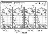
- FIGS. 3 A to 3 Cillustrate graphs showing examples of control strategy options
- FIG. 4illustrates an embodiment of a system in accordance with the present invention.
- probesi.e. electrosurgical devices
- Real-time temperature monitoringis achieved through the use of probe sensors e.g. thermocouples at the probe tip.
- probe sensorse.g. thermocouples at the probe tip.
- these systemsemploy a multiplexing technique involving rapid switching between active channels so as to facilitate effective temperature-controlled energy delivery to multiple channels within a single procedure.
- a channelis an energy delivery pathway.
- pain management generatorsare limited to certain maximum power output levels. For example, for regulatory reasons, many pain management generators have in the past been limited to 50 watts total power output.
- the present inventorshave conceived of and reduced to practice embodiments of systems and methods for all of a number of probes substantially reaching a set temperature (a pre-determined threshold) in the shortest time (i.e. with the shortest delay introduced due to power limitations) when powered by a generator, the systems and methods including a controller of a generator system allocating power proportionally to the probes such that all of the probes reach the pre-determined threshold at approximately the same time.
- the generatorprovides the allocated power to channels associated with the probes.
- a control systemi.e. a controller
- the control systemincludes an algorithm for determining how to apportion average power effectively between energy delivery channels in an underpowered situation so as to minimize overall procedure time.
- the algorithmassists in ensuring that all relevant probes complete ramping and reach and maintain a set temperature with minimal delay due to power restrictions.
- the types of energyinclude, at least, electrical energy, electrical power, electrical RF (radiofrequency) energy, and pulsed radiofrequency signals.
- Some embodimentsinclude a bipolar channel comprising two monopolar probes. Some embodiments include a monopolar channel comprising a monopolar probe and a grounding pad. Some embodiments include a combination of monopolar and bipolar channels.
- the inventionincludes an algorithm that uses proportional power allocation when the total power requested by the generator's control strategy to maintain the desired temperature profile across active channels exceeds the maximum capacity of the generator (e.g. nominally 50 watts) i.e. total power required first exceeds the total available power.
- This algorithmassigns power to the active channels proportionally based on the generator's requested power for each channel.
- the delivered power to each channelis calculated by dividing the real-time controller requested power for each channel by the total requested power across all channels at the time and then multiplying by the total power limit (e.g. nominally 50 watts).
- the controllerdefines the requested power for each channel based on the temperature error of the channel and the controller parameters assigned by the generator specific to that channel.
- the requested power for each channelis the power the controller algorithm determines the channel should receive to allow for the minimum heating time.
- temperature erroris the difference between the control temperature (i.e. the chosen set point) and the measured temperature wherein the temperature is often measured by a sensor in a probe connected to the channel. Certain factors could impact the controller parameters applied to a specific channel including the probe size, probe type and channel configuration (monopolar or bipolar).
- This algorithmwill update in real-time so as to continually scale the delivered power proportionally based on the power requirements of each channel. In some embodiments, updating in real-time comprises monitoring the temperature every 24 ms (milliseconds).
- the algorithmis often useful during the ramping phase of energy delivery, during which underpowered situations are common.
- This algorithmensures that each channel should ramp up towards the set temperature at similar rates of temperature change, thus all reaching the set temperature at approximately the same time in typical situations.
- each channelhas the same (i.e. identical) set temperature.
- the situation where one or more channels are delayed to facilitate other channels completing the rampis substantially minimized.
- situations in which different channels are running at the set temperature for substantially different durationsare substantially avoided, as is the need to provide additional time for one or more channels. As a result, the total procedure time is minimized.
- a feature of the inventionis a control strategy that ensures that power is applied proportionately to the channel(s) that require it most, based on the relative requested powers determined by the generator for each channel in real-time.
- This control strategycould be achieved through various means, including (1) by varying the instantaneous power delivered to each channel, (2) by varying the relative duration (i.e., duty cycle) of power delivery to each channel, or (3) through a hybrid strategy that involves varying both instantaneous power and relative duration in which switching between channels is achieved. All 3 options can apply in underpowered situations. Any of these options can be used as a method of ensuring that the proportional power scaling described herein is applied appropriately.
- Each of the 3 optionscan utilize a control strategy based on discrete time periods.
- these time periodsare in of the order of 24 ms each and are made up of individual frames of shorter duration (e.g., 2 ms each).
- the controllerdetermines which channel will deliver energy during each frame, as well as how much instantaneous power will be delivered for the duration of each frame. At the beginning of each time period, the controller can assign the power output for each frame within the longer time periods.
- the examples described hereingenerally use a time period of 24 ms and a frame of 2 ms, this is not intended to be limiting, and alternative embodiments comprise a time period of about 10 ms to about 100 ms and a frame of about 1 ms to about 5 ms.
- option (2)which includes varying duty cycle
- the power output within each frameremains constant but the division of frames between active channels may vary.
- This optionis pertinent in underpowered situations to help continually apply a maximum power (e.g. 50 watts) in times of high power requirements.
- a maximum powere.g. 50 watts
- this techniquetypically does not require spikes in instantaneous power, which can be complex to achieve and potentially dangerous.
- the control strategymanages the requirements of the channel(s) with the most need, while also ensuring that the other channels continue to receive power at sufficient intervals so as not to be adversely affected.
- Option (3)which combines options (1) and (2), offers the greatest flexibility.
- One particular embodiment that utilizes a version of this hybrid methodis detailed herein below with respect to FIG. 3 C .
- the control algorithmuses the proportional power allocation as described herein. For example, in some embodiments, a time period of 24 ms is divided into discrete frames of 2 ms each and the division of frames within a time period by the control algorithm defines the duty cycles of the channels. If needed, the duty cycles can vary from one time period to the next, so as to ensure that the power is proportionally scaled based on requested power. Within each of these discrete frames, the power is delivered to one of the active channels and is typically maintained at close to 50 watts instantaneous power. In this way, the maximum instantaneous power will not typically need to be much above 50 watts.
- instantaneous powercan rise slightly above 50 watts (but never above approximately 70 watts) to compensate for some brief down time when switching between channels.
- the algorithmalso ensures that each active channel receives at least 1 frame within a 24 ms time period. This is to ensure that all channels continue to perform effectively, even those that require very little power. As a result of this, channels that do require more power will be able to receive higher instantaneous power to ensure that the full 50 watts average power is utilized.
- each channel's controller parameterswill be identical and power will be apportioned based solely on the relative differences between the current temperature and the control temperature for each probe.
- the control temperatureis the temperature that the probe should ideally be at during any given time period based on a PID (proportional-integral-derivative) control strategy used when the total power required is less than the total available power. This control temperature varies during ramping but matches the set temperature after the ramp time has completed.
- the algorithmdetermines in real time which channel requires the most power and allocates proportionally higher power to that channel.
- the algorithmcontinues to track total power required. When this drops below 50 watts, the control system switches back to regular power control, with the allotment of power determined by actual need without the proportional power allocation described herein i.e. non-proportional power allocation.
- the inventionis applicable to different types of probes, including internally cooled probes.
- the inventionis pertinent to multi-channel internally cooled RF electrical procedures since the power requirements of internally cooled probes are typically higher than those of their non-cooled counterparts.
- FIG. 4illustrates an example of a system 110 the algorithm may be used with.
- System 110includes a generator 112 having four channels as indicated by GUI 113 .
- FIG. 4illustrates two probes 116 (rather than three or four probes) which are connected to the channels of generator 112 via way of hub 111 , enabling the probes 116 to deliver energy.
- Hub 111is connected to the generator 112 via a single cable (not shown in FIG. 4 ) i.e. there is no cable directly connecting a probe to a channel connector.
- the hub 111comprises a plurality of connectors (four) each defining a respective channel. Alternative hub embodiments have less than or more than four connectors.
- the probes 116are connected directly to generator 112 via a plurality of physical connectors on the generator i.e. without the use of a hub such as hub 111 .
- the system of FIG. 4includes a pump 114 and tubing 115 for providing cooling fluid to probes 116 .
- Some alternative systemsonly include uncooled probes and accordingly do not include a pump or fluid tubing.
- the algorithmis applicable to systems comprising cooled probes, uncooled probes, or a combination of cooled and uncooled probes.
- FIG. 1provides a flowchart summarizing the algorithm.
- the controllerdefines the requested power for each channel based on the temperature error of the channel and the controller parameters for that channel.
- temperature erroris the difference between the control temperature (i.e. the chosen set point) and the measured temperature with the temperature being measured by a temperature sensor.
- the controllercalculates the total requested power, which is the sum of the channel requested power for each of the channels.
- the P total total power requested for all active channelsis compared to the Maximum Output of the generator. If the Maximum Output of the generator is greater than the total power requested, then each channel is provided (in step 230 ) with the requested power as calculated by the controller. From step 230 , the algorithm loops back to step 200 .
- step 220If in step 220 , the total P total power requested for all active channels is greater than the Maximum Output of the generator, the power allocated for a channel is determined (in step 240 ) by multiplying the P channel requested channel requested channel P requested power of a channel with the Maximum Output of the generator and dividing the product by the total P total total power requested for all active channels. Step 240 is performed for each channel requiring power. From step 240 , the algorithm loops back to step 200 . Following the allocation of power by the controller algorithm, the generator provides the allocated power to each of the channels.
- FIGS. 2 A to 2 Cprovide graphical examples of power being delivered.
- Channel indicator 100corresponds with a channel A.
- the temperature of each channelis ramping at the specified rate.
- the controlleris currently defining a requested power of 12 watts for each channel and 12 watts is being supplied to each channel, as indicated by output power 104 . Since the generator system has a 50 watts power limit, there is sufficient power for each channel at this stage.
- the temperature plots 101plot the temperatures of the probes attached to the channels.
- Power plots 103plot the power levels delivered to the probes.
- an underpowered situationhas been reached as indicated by the total power across the 4 channels totaling 50 watts (the total shown by the output power 104 ), resulting in the rate of temperature ramp for each channel decreasing slightly (temperature plot 101 ).
- the controllerdetermines Probe A requires more power than the other probes and therefore more power is delivered to channel A than the other channels.
- the power requested by the controller for channel Ais 30 watts, and the power requested for each of the other channels is 10 watts. As a result, a total of 60 watts is requested which is not feasible since the generator system has a 50 watts power limit.
- the requested power of each channelwill be scaled down by a factor of 50/60 i.e. each of the requested powers is multiplied by 50/60.
- Probe Ais delivering 25 watts while the other channels (and associated probes) are each delivering 8.3 watts.
- the rate of temperature rampstays the same across all four channels (temperature plot 101 ).
- each channelreaches the set temperature 105 at approximately the same time (see temperature plot 101 ).
- the durations at the set temperature 105 for each channelwill be the same.
- having all channels reach set temperature at the same timewill minimize the overall procedure duration.
- Some embodiments using standard (un-cooled) probeshave a set point of about 80° C., while other embodiments have a set point ranging from about 70° C. to about 90° C. Some embodiments using cooled probes have a set point ranging from about 60° C. to about 75° C.
- FIG. 3provides an example of some different options for the method of controlling power output.
- the proportional power scaling algorithmcould function with any of these methods.
- FIGS. 3 A, 3 B, and 3 Can example is illustrated in which two channels (and the corresponding probes) are active and being allocated a total of 50 watts average power, and Probe A is being allocated three times more power than Probe B.
- FIG. 3 Adepicts a control strategy in which the duty cycle is fixed and the instantaneous power is adjusted to accommodate the average power requirements.
- each probeis active for the same duration.
- Probe Ais provided with an instantaneous power of 75 watts.
- FIG. 3 Bdepicts a control strategy in which the instantaneous power is fixed and the duty cycle is adjusted.
- the duty cycle of probe Ais three times the duty cycle of probe B.
- the benefit hereis that the instantaneous power doesn't have to increase above 50 watts.
- FIG. 3 Cdepicts a hybrid control strategy in which both the instantaneous power and the duty cycle of channel A is increased above that of channel B.
Landscapes
- Health & Medical Sciences (AREA)
- Surgery (AREA)
- Engineering & Computer Science (AREA)
- Life Sciences & Earth Sciences (AREA)
- Biomedical Technology (AREA)
- Otolaryngology (AREA)
- Nuclear Medicine, Radiotherapy & Molecular Imaging (AREA)
- Plasma & Fusion (AREA)
- Physics & Mathematics (AREA)
- Heart & Thoracic Surgery (AREA)
- Medical Informatics (AREA)
- Molecular Biology (AREA)
- Animal Behavior & Ethology (AREA)
- General Health & Medical Sciences (AREA)
- Public Health (AREA)
- Veterinary Medicine (AREA)
- Surgical Instruments (AREA)
Abstract
Description
Claims (30)
Priority Applications (1)
| Application Number | Priority Date | Filing Date | Title |
|---|---|---|---|
| US16/472,092US11523857B2 (en) | 2016-12-22 | 2017-12-21 | Multiplexing algorithm with power allocation |
Applications Claiming Priority (3)
| Application Number | Priority Date | Filing Date | Title |
|---|---|---|---|
| US201662438336P | 2016-12-22 | 2016-12-22 | |
| US16/472,092US11523857B2 (en) | 2016-12-22 | 2017-12-21 | Multiplexing algorithm with power allocation |
| PCT/IB2017/058296WO2018116247A1 (en) | 2016-12-22 | 2017-12-21 | Multiplexing algorithm with power allocation |
Publications (2)
| Publication Number | Publication Date |
|---|---|
| US20200085487A1 US20200085487A1 (en) | 2020-03-19 |
| US11523857B2true US11523857B2 (en) | 2022-12-13 |
Family
ID=62626360
Family Applications (1)
| Application Number | Title | Priority Date | Filing Date |
|---|---|---|---|
| US16/472,092Active2040-02-17US11523857B2 (en) | 2016-12-22 | 2017-12-21 | Multiplexing algorithm with power allocation |
Country Status (2)
| Country | Link |
|---|---|
| US (1) | US11523857B2 (en) |
| WO (1) | WO2018116247A1 (en) |
Families Citing this family (136)
| Publication number | Priority date | Publication date | Assignee | Title |
|---|---|---|---|---|
| US11871901B2 (en) | 2012-05-20 | 2024-01-16 | Cilag Gmbh International | Method for situational awareness for surgical network or surgical network connected device capable of adjusting function based on a sensed situation or usage |
| US11504192B2 (en) | 2014-10-30 | 2022-11-22 | Cilag Gmbh International | Method of hub communication with surgical instrument systems |
| US11911045B2 (en) | 2017-10-30 | 2024-02-27 | Cllag GmbH International | Method for operating a powered articulating multi-clip applier |
| US11801098B2 (en) | 2017-10-30 | 2023-10-31 | Cilag Gmbh International | Method of hub communication with surgical instrument systems |
| US11510741B2 (en) | 2017-10-30 | 2022-11-29 | Cilag Gmbh International | Method for producing a surgical instrument comprising a smart electrical system |
| US11026687B2 (en) | 2017-10-30 | 2021-06-08 | Cilag Gmbh International | Clip applier comprising clip advancing systems |
| US11564756B2 (en) | 2017-10-30 | 2023-01-31 | Cilag Gmbh International | Method of hub communication with surgical instrument systems |
| US11317919B2 (en) | 2017-10-30 | 2022-05-03 | Cilag Gmbh International | Clip applier comprising a clip crimping system |
| US11925373B2 (en) | 2017-10-30 | 2024-03-12 | Cilag Gmbh International | Surgical suturing instrument comprising a non-circular needle |
| US11311342B2 (en) | 2017-10-30 | 2022-04-26 | Cilag Gmbh International | Method for communicating with surgical instrument systems |
| US11291510B2 (en) | 2017-10-30 | 2022-04-05 | Cilag Gmbh International | Method of hub communication with surgical instrument systems |
| US11419630B2 (en) | 2017-12-28 | 2022-08-23 | Cilag Gmbh International | Surgical system distributed processing |
| US11571234B2 (en) | 2017-12-28 | 2023-02-07 | Cilag Gmbh International | Temperature control of ultrasonic end effector and control system therefor |
| US11364075B2 (en) | 2017-12-28 | 2022-06-21 | Cilag Gmbh International | Radio frequency energy device for delivering combined electrical signals |
| US20190201090A1 (en) | 2017-12-28 | 2019-07-04 | Ethicon Llc | Capacitive coupled return path pad with separable array elements |
| US11304763B2 (en) | 2017-12-28 | 2022-04-19 | Cilag Gmbh International | Image capturing of the areas outside the abdomen to improve placement and control of a surgical device in use |
| US11786245B2 (en) | 2017-12-28 | 2023-10-17 | Cilag Gmbh International | Surgical systems with prioritized data transmission capabilities |
| US11633237B2 (en) | 2017-12-28 | 2023-04-25 | Cilag Gmbh International | Usage and technique analysis of surgeon / staff performance against a baseline to optimize device utilization and performance for both current and future procedures |
| US10918310B2 (en) | 2018-01-03 | 2021-02-16 | Biosense Webster (Israel) Ltd. | Fast anatomical mapping (FAM) using volume filling |
| US20190201112A1 (en) | 2017-12-28 | 2019-07-04 | Ethicon Llc | Computer implemented interactive surgical systems |
| US20190201142A1 (en) | 2017-12-28 | 2019-07-04 | Ethicon Llc | Automatic tool adjustments for robot-assisted surgical platforms |
| US11744604B2 (en) | 2017-12-28 | 2023-09-05 | Cilag Gmbh International | Surgical instrument with a hardware-only control circuit |
| US11389164B2 (en) | 2017-12-28 | 2022-07-19 | Cilag Gmbh International | Method of using reinforced flexible circuits with multiple sensors to optimize performance of radio frequency devices |
| US11559308B2 (en) | 2017-12-28 | 2023-01-24 | Cilag Gmbh International | Method for smart energy device infrastructure |
| US11026751B2 (en) | 2017-12-28 | 2021-06-08 | Cilag Gmbh International | Display of alignment of staple cartridge to prior linear staple line |
| US11284936B2 (en) | 2017-12-28 | 2022-03-29 | Cilag Gmbh International | Surgical instrument having a flexible electrode |
| US11013563B2 (en) | 2017-12-28 | 2021-05-25 | Ethicon Llc | Drive arrangements for robot-assisted surgical platforms |
| US11308075B2 (en) | 2017-12-28 | 2022-04-19 | Cilag Gmbh International | Surgical network, instrument, and cloud responses based on validation of received dataset and authentication of its source and integrity |
| US10892995B2 (en) | 2017-12-28 | 2021-01-12 | Ethicon Llc | Surgical network determination of prioritization of communication, interaction, or processing based on system or device needs |
| US11304745B2 (en) | 2017-12-28 | 2022-04-19 | Cilag Gmbh International | Surgical evacuation sensing and display |
| US11179175B2 (en) | 2017-12-28 | 2021-11-23 | Cilag Gmbh International | Controlling an ultrasonic surgical instrument according to tissue location |
| US11696760B2 (en) | 2017-12-28 | 2023-07-11 | Cilag Gmbh International | Safety systems for smart powered surgical stapling |
| US11464535B2 (en) | 2017-12-28 | 2022-10-11 | Cilag Gmbh International | Detection of end effector emersion in liquid |
| US11234756B2 (en) | 2017-12-28 | 2022-02-01 | Cilag Gmbh International | Powered surgical tool with predefined adjustable control algorithm for controlling end effector parameter |
| US11202570B2 (en) | 2017-12-28 | 2021-12-21 | Cilag Gmbh International | Communication hub and storage device for storing parameters and status of a surgical device to be shared with cloud based analytics systems |
| US11304699B2 (en) | 2017-12-28 | 2022-04-19 | Cilag Gmbh International | Method for adaptive control schemes for surgical network control and interaction |
| US11076921B2 (en) | 2017-12-28 | 2021-08-03 | Cilag Gmbh International | Adaptive control program updates for surgical hubs |
| US11659023B2 (en) | 2017-12-28 | 2023-05-23 | Cilag Gmbh International | Method of hub communication |
| US11324557B2 (en) | 2017-12-28 | 2022-05-10 | Cilag Gmbh International | Surgical instrument with a sensing array |
| WO2019133144A1 (en) | 2017-12-28 | 2019-07-04 | Ethicon Llc | Detection and escalation of security responses of surgical instruments to increasing severity threats |
| US11376002B2 (en) | 2017-12-28 | 2022-07-05 | Cilag Gmbh International | Surgical instrument cartridge sensor assemblies |
| US11291495B2 (en) | 2017-12-28 | 2022-04-05 | Cilag Gmbh International | Interruption of energy due to inadvertent capacitive coupling |
| US11786251B2 (en) | 2017-12-28 | 2023-10-17 | Cilag Gmbh International | Method for adaptive control schemes for surgical network control and interaction |
| US11166772B2 (en) | 2017-12-28 | 2021-11-09 | Cilag Gmbh International | Surgical hub coordination of control and communication of operating room devices |
| US11464559B2 (en) | 2017-12-28 | 2022-10-11 | Cilag Gmbh International | Estimating state of ultrasonic end effector and control system therefor |
| US20190206569A1 (en) | 2017-12-28 | 2019-07-04 | Ethicon Llc | Method of cloud based data analytics for use with the hub |
| US20190201039A1 (en) | 2017-12-28 | 2019-07-04 | Ethicon Llc | Situational awareness of electrosurgical systems |
| US11903601B2 (en) | 2017-12-28 | 2024-02-20 | Cilag Gmbh International | Surgical instrument comprising a plurality of drive systems |
| US11317937B2 (en) | 2018-03-08 | 2022-05-03 | Cilag Gmbh International | Determining the state of an ultrasonic end effector |
| US11529187B2 (en) | 2017-12-28 | 2022-12-20 | Cilag Gmbh International | Surgical evacuation sensor arrangements |
| US11602393B2 (en) | 2017-12-28 | 2023-03-14 | Cilag Gmbh International | Surgical evacuation sensing and generator control |
| US11857152B2 (en) | 2017-12-28 | 2024-01-02 | Cilag Gmbh International | Surgical hub spatial awareness to determine devices in operating theater |
| US11832899B2 (en) | 2017-12-28 | 2023-12-05 | Cilag Gmbh International | Surgical systems with autonomously adjustable control programs |
| US11419667B2 (en) | 2017-12-28 | 2022-08-23 | Cilag Gmbh International | Ultrasonic energy device which varies pressure applied by clamp arm to provide threshold control pressure at a cut progression location |
| US11540855B2 (en) | 2017-12-28 | 2023-01-03 | Cilag Gmbh International | Controlling activation of an ultrasonic surgical instrument according to the presence of tissue |
| US12396806B2 (en) | 2017-12-28 | 2025-08-26 | Cilag Gmbh International | Adjustment of a surgical device function based on situational awareness |
| US11969216B2 (en) | 2017-12-28 | 2024-04-30 | Cilag Gmbh International | Surgical network recommendations from real time analysis of procedure variables against a baseline highlighting differences from the optimal solution |
| US11832840B2 (en) | 2017-12-28 | 2023-12-05 | Cilag Gmbh International | Surgical instrument having a flexible circuit |
| US11410259B2 (en) | 2017-12-28 | 2022-08-09 | Cilag Gmbh International | Adaptive control program updates for surgical devices |
| US11864728B2 (en) | 2017-12-28 | 2024-01-09 | Cilag Gmbh International | Characterization of tissue irregularities through the use of mono-chromatic light refractivity |
| US10758310B2 (en) | 2017-12-28 | 2020-09-01 | Ethicon Llc | Wireless pairing of a surgical device with another device within a sterile surgical field based on the usage and situational awareness of devices |
| US11666331B2 (en) | 2017-12-28 | 2023-06-06 | Cilag Gmbh International | Systems for detecting proximity of surgical end effector to cancerous tissue |
| US11311306B2 (en) | 2017-12-28 | 2022-04-26 | Cilag Gmbh International | Surgical systems for detecting end effector tissue distribution irregularities |
| US12376855B2 (en) | 2017-12-28 | 2025-08-05 | Cilag Gmbh International | Safety systems for smart powered surgical stapling |
| US11896322B2 (en) | 2017-12-28 | 2024-02-13 | Cilag Gmbh International | Sensing the patient position and contact utilizing the mono-polar return pad electrode to provide situational awareness to the hub |
| US11432885B2 (en) | 2017-12-28 | 2022-09-06 | Cilag Gmbh International | Sensing arrangements for robot-assisted surgical platforms |
| US11132462B2 (en) | 2017-12-28 | 2021-09-28 | Cilag Gmbh International | Data stripping method to interrogate patient records and create anonymized record |
| US12062442B2 (en) | 2017-12-28 | 2024-08-13 | Cilag Gmbh International | Method for operating surgical instrument systems |
| US11969142B2 (en) | 2017-12-28 | 2024-04-30 | Cilag Gmbh International | Method of compressing tissue within a stapling device and simultaneously displaying the location of the tissue within the jaws |
| US12127729B2 (en) | 2017-12-28 | 2024-10-29 | Cilag Gmbh International | Method for smoke evacuation for surgical hub |
| US11266468B2 (en) | 2017-12-28 | 2022-03-08 | Cilag Gmbh International | Cooperative utilization of data derived from secondary sources by intelligent surgical hubs |
| US11109866B2 (en) | 2017-12-28 | 2021-09-07 | Cilag Gmbh International | Method for circular stapler control algorithm adjustment based on situational awareness |
| US12096916B2 (en) | 2017-12-28 | 2024-09-24 | Cilag Gmbh International | Method of sensing particulate from smoke evacuated from a patient, adjusting the pump speed based on the sensed information, and communicating the functional parameters of the system to the hub |
| US11304720B2 (en) | 2017-12-28 | 2022-04-19 | Cilag Gmbh International | Activation of energy devices |
| US11818052B2 (en) | 2017-12-28 | 2023-11-14 | Cilag Gmbh International | Surgical network determination of prioritization of communication, interaction, or processing based on system or device needs |
| US11424027B2 (en) | 2017-12-28 | 2022-08-23 | Cilag Gmbh International | Method for operating surgical instrument systems |
| US11257589B2 (en) | 2017-12-28 | 2022-02-22 | Cilag Gmbh International | Real-time analysis of comprehensive cost of all instrumentation used in surgery utilizing data fluidity to track instruments through stocking and in-house processes |
| US11998193B2 (en) | 2017-12-28 | 2024-06-04 | Cilag Gmbh International | Method for usage of the shroud as an aspect of sensing or controlling a powered surgical device, and a control algorithm to adjust its default operation |
| US11937769B2 (en) | 2017-12-28 | 2024-03-26 | Cilag Gmbh International | Method of hub communication, processing, storage and display |
| US11446052B2 (en) | 2017-12-28 | 2022-09-20 | Cilag Gmbh International | Variation of radio frequency and ultrasonic power level in cooperation with varying clamp arm pressure to achieve predefined heat flux or power applied to tissue |
| US11559307B2 (en) | 2017-12-28 | 2023-01-24 | Cilag Gmbh International | Method of robotic hub communication, detection, and control |
| US11612444B2 (en) | 2017-12-28 | 2023-03-28 | Cilag Gmbh International | Adjustment of a surgical device function based on situational awareness |
| US11576677B2 (en) | 2017-12-28 | 2023-02-14 | Cilag Gmbh International | Method of hub communication, processing, display, and cloud analytics |
| US11278281B2 (en) | 2017-12-28 | 2022-03-22 | Cilag Gmbh International | Interactive surgical system |
| US11896443B2 (en) | 2017-12-28 | 2024-02-13 | Cilag Gmbh International | Control of a surgical system through a surgical barrier |
| US11423007B2 (en) | 2017-12-28 | 2022-08-23 | Cilag Gmbh International | Adjustment of device control programs based on stratified contextual data in addition to the data |
| US11589888B2 (en) | 2017-12-28 | 2023-02-28 | Cilag Gmbh International | Method for controlling smart energy devices |
| US11253315B2 (en) | 2017-12-28 | 2022-02-22 | Cilag Gmbh International | Increasing radio frequency to create pad-less monopolar loop |
| US11678881B2 (en) | 2017-12-28 | 2023-06-20 | Cilag Gmbh International | Spatial awareness of surgical hubs in operating rooms |
| US12303159B2 (en) | 2018-03-08 | 2025-05-20 | Cilag Gmbh International | Methods for estimating and controlling state of ultrasonic end effector |
| US11534196B2 (en) | 2018-03-08 | 2022-12-27 | Cilag Gmbh International | Using spectroscopy to determine device use state in combo instrument |
| US11259830B2 (en) | 2018-03-08 | 2022-03-01 | Cilag Gmbh International | Methods for controlling temperature in ultrasonic device |
| US11986233B2 (en) | 2018-03-08 | 2024-05-21 | Cilag Gmbh International | Adjustment of complex impedance to compensate for lost power in an articulating ultrasonic device |
| US11278280B2 (en) | 2018-03-28 | 2022-03-22 | Cilag Gmbh International | Surgical instrument comprising a jaw closure lockout |
| US11090047B2 (en) | 2018-03-28 | 2021-08-17 | Cilag Gmbh International | Surgical instrument comprising an adaptive control system |
| US11589865B2 (en) | 2018-03-28 | 2023-02-28 | Cilag Gmbh International | Methods for controlling a powered surgical stapler that has separate rotary closure and firing systems |
| US11471156B2 (en) | 2018-03-28 | 2022-10-18 | Cilag Gmbh International | Surgical stapling devices with improved rotary driven closure systems |
| US11213294B2 (en) | 2018-03-28 | 2022-01-04 | Cilag Gmbh International | Surgical instrument comprising co-operating lockout features |
| US10980599B2 (en)* | 2018-07-05 | 2021-04-20 | Avent, Inc. | System and method for adjusting available power per probe during an ablation procedure |
| US11804679B2 (en) | 2018-09-07 | 2023-10-31 | Cilag Gmbh International | Flexible hand-switch circuit |
| US11923084B2 (en) | 2018-09-07 | 2024-03-05 | Cilag Gmbh International | First and second communication protocol arrangement for driving primary and secondary devices through a single port |
| US12144136B2 (en) | 2018-09-07 | 2024-11-12 | Cilag Gmbh International | Modular surgical energy system with module positional awareness with digital logic |
| US20200078113A1 (en) | 2018-09-07 | 2020-03-12 | Ethicon Llc | Port presence detection system for modular energy system |
| US11510720B2 (en) | 2018-09-07 | 2022-11-29 | Cilag Gmbh International | Managing simultaneous monopolar outputs using duty cycle and synchronization |
| WO2020132423A1 (en)* | 2018-12-20 | 2020-06-25 | Medtronic, Inc. | Method of power distribution |
| US11464511B2 (en) | 2019-02-19 | 2022-10-11 | Cilag Gmbh International | Surgical staple cartridges with movable authentication key arrangements |
| US11369377B2 (en) | 2019-02-19 | 2022-06-28 | Cilag Gmbh International | Surgical stapling assembly with cartridge based retainer configured to unlock a firing lockout |
| US11331100B2 (en) | 2019-02-19 | 2022-05-17 | Cilag Gmbh International | Staple cartridge retainer system with authentication keys |
| US11357503B2 (en) | 2019-02-19 | 2022-06-14 | Cilag Gmbh International | Staple cartridge retainers with frangible retention features and methods of using same |
| US11317915B2 (en) | 2019-02-19 | 2022-05-03 | Cilag Gmbh International | Universal cartridge based key feature that unlocks multiple lockout arrangements in different surgical staplers |
| US11218822B2 (en) | 2019-03-29 | 2022-01-04 | Cilag Gmbh International | Audio tone construction for an energy module of a modular energy system |
| US11331152B2 (en)* | 2019-05-20 | 2022-05-17 | Avent, Inc. | System and method for an improved graphical user interface that provides independent control of multiple radiofrequency probes during an ablation procedure |
| USD952144S1 (en) | 2019-06-25 | 2022-05-17 | Cilag Gmbh International | Surgical staple cartridge retainer with firing system authentication key |
| USD950728S1 (en) | 2019-06-25 | 2022-05-03 | Cilag Gmbh International | Surgical staple cartridge |
| USD964564S1 (en) | 2019-06-25 | 2022-09-20 | Cilag Gmbh International | Surgical staple cartridge retainer with a closure system authentication key |
| US11036277B2 (en)* | 2019-08-15 | 2021-06-15 | Intel Corporation | Methods and apparatus to dynamically throttle compute engines |
| USD924139S1 (en) | 2019-09-05 | 2021-07-06 | Ethicon Llc | Energy module with a backplane connector |
| USD939545S1 (en) | 2019-09-05 | 2021-12-28 | Cilag Gmbh International | Display panel or portion thereof with graphical user interface for energy module |
| USD928725S1 (en) | 2019-09-05 | 2021-08-24 | Cilag Gmbh International | Energy module |
| USD928726S1 (en) | 2019-09-05 | 2021-08-24 | Cilag Gmbh International | Energy module monopolar port |
| US12127777B2 (en) | 2021-03-30 | 2024-10-29 | Cilag Gmbh International | Energy delivery mitigations for modular energy systems |
| US11980411B2 (en) | 2021-03-30 | 2024-05-14 | Cilag Gmbh International | Header for modular energy system |
| US11950860B2 (en) | 2021-03-30 | 2024-04-09 | Cilag Gmbh International | User interface mitigation techniques for modular energy systems |
| US11857252B2 (en) | 2021-03-30 | 2024-01-02 | Cilag Gmbh International | Bezel with light blocking features for modular energy system |
| US11968776B2 (en) | 2021-03-30 | 2024-04-23 | Cilag Gmbh International | Method for mechanical packaging for modular energy system |
| US11978554B2 (en) | 2021-03-30 | 2024-05-07 | Cilag Gmbh International | Radio frequency identification token for wireless surgical instruments |
| US12228987B2 (en) | 2021-03-30 | 2025-02-18 | Cilag Gmbh International | Method for energy delivery for modular energy system |
| US12004824B2 (en) | 2021-03-30 | 2024-06-11 | Cilag Gmbh International | Architecture for modular energy system |
| US12235697B2 (en) | 2021-03-30 | 2025-02-25 | Cilag Gmbh International | Backplane connector attachment mechanism for modular energy system |
| US12369994B2 (en) | 2021-03-30 | 2025-07-29 | Cilag Gmbh International | Modular energy system with multi-energy port splitter for multiple energy devices |
| US12329437B2 (en) | 2021-03-30 | 2025-06-17 | Cilag Gmbh International | Surgical proceduralization via modular energy system |
| US11963727B2 (en) | 2021-03-30 | 2024-04-23 | Cilag Gmbh International | Method for system architecture for modular energy system |
| US12142373B2 (en) | 2021-03-30 | 2024-11-12 | Cilag Gmbh International | Modular energy system with hardware mitigated communication |
| US12040749B2 (en) | 2021-03-30 | 2024-07-16 | Cilag Gmbh International | Modular energy system with dual amplifiers and techniques for updating parameters thereof |
| US20220331051A1 (en) | 2021-04-14 | 2022-10-20 | Cilag Gmbh International | Utilizing contextual parameters of one or more surgical devices to predict a frequency interval for displaying surgical information |
| US12079460B2 (en) | 2022-06-28 | 2024-09-03 | Cilag Gmbh International | Profiles for modular energy system |
Citations (10)
| Publication number | Priority date | Publication date | Assignee | Title |
|---|---|---|---|---|
| US5300068A (en) | 1992-04-21 | 1994-04-05 | St. Jude Medical, Inc. | Electrosurgical apparatus |
| US6346104B2 (en)* | 1996-04-30 | 2002-02-12 | Western Sydney Area Health Service | System for simultaneous unipolar multi-electrode ablation |
| US6936047B2 (en)* | 2000-05-12 | 2005-08-30 | Agility Capital Llc | Multi-channel RF energy delivery with coagulum reduction |
| US20070129726A1 (en) | 2005-05-12 | 2007-06-07 | Eder Joseph C | Electrocautery method and apparatus |
| US20100324548A1 (en)* | 2007-02-25 | 2010-12-23 | Baylis Medical Company Inc. | Methods for control of energy delivery to multiple energy delivery devices |
| US20110152853A1 (en) | 2009-12-18 | 2011-06-23 | Prakash Manley | Microwave Ablation System With Dielectric Temperature Probe |
| WO2016014198A1 (en) | 2014-07-24 | 2016-01-28 | Arthrocare Corporation | Electrosurgical system and method having enhanced arc prevention |
| US20170049513A1 (en)* | 2009-11-06 | 2017-02-23 | Cosman Medical, Inc. | Multiple electrode generator |
| US20200197070A1 (en)* | 2018-12-20 | 2020-06-25 | Medtronic, Inc. | Method of power distribution |
| US10980599B2 (en)* | 2018-07-05 | 2021-04-20 | Avent, Inc. | System and method for adjusting available power per probe during an ablation procedure |
- 2017
- 2017-12-21USUS16/472,092patent/US11523857B2/enactiveActive
- 2017-12-21WOPCT/IB2017/058296patent/WO2018116247A1/ennot_activeCeased
Patent Citations (10)
| Publication number | Priority date | Publication date | Assignee | Title |
|---|---|---|---|---|
| US5300068A (en) | 1992-04-21 | 1994-04-05 | St. Jude Medical, Inc. | Electrosurgical apparatus |
| US6346104B2 (en)* | 1996-04-30 | 2002-02-12 | Western Sydney Area Health Service | System for simultaneous unipolar multi-electrode ablation |
| US6936047B2 (en)* | 2000-05-12 | 2005-08-30 | Agility Capital Llc | Multi-channel RF energy delivery with coagulum reduction |
| US20070129726A1 (en) | 2005-05-12 | 2007-06-07 | Eder Joseph C | Electrocautery method and apparatus |
| US20100324548A1 (en)* | 2007-02-25 | 2010-12-23 | Baylis Medical Company Inc. | Methods for control of energy delivery to multiple energy delivery devices |
| US20170049513A1 (en)* | 2009-11-06 | 2017-02-23 | Cosman Medical, Inc. | Multiple electrode generator |
| US20110152853A1 (en) | 2009-12-18 | 2011-06-23 | Prakash Manley | Microwave Ablation System With Dielectric Temperature Probe |
| WO2016014198A1 (en) | 2014-07-24 | 2016-01-28 | Arthrocare Corporation | Electrosurgical system and method having enhanced arc prevention |
| US10980599B2 (en)* | 2018-07-05 | 2021-04-20 | Avent, Inc. | System and method for adjusting available power per probe during an ablation procedure |
| US20200197070A1 (en)* | 2018-12-20 | 2020-06-25 | Medtronic, Inc. | Method of power distribution |
Non-Patent Citations (2)
| Title |
|---|
| International Preliminary Report on Patentability from International Application No. PCT/IB2017/058296, dated Jun. 25, 2019, 4 pp. |
| International Search Report and Written Opinion of International Application No. PCT/IB2017/058296, dated Apr. 19, 2018, 8 pp. |
Also Published As
| Publication number | Publication date |
|---|---|
| WO2018116247A1 (en) | 2018-06-28 |
| US20200085487A1 (en) | 2020-03-19 |
Similar Documents
| Publication | Publication Date | Title |
|---|---|---|
| US11523857B2 (en) | Multiplexing algorithm with power allocation | |
| US7252664B2 (en) | System and method for multi-channel RF energy delivery with coagulum reduction | |
| US20210275825A1 (en) | Rf device for skin and fat treatment | |
| WO2018116273A1 (en) | Electrosurgical system with coordinated energy and fluid delivery | |
| US8821487B2 (en) | Temperature regulating patient return electrode and return electrode monitoring system | |
| EP1280467B1 (en) | Multi-channel rf energy delivery with coagulum reduction | |
| EP2653128B1 (en) | Control of energy delivery to multiple energy delivery devices | |
| US20070078502A1 (en) | Method and apparatus for estimating a local impedance factor | |
| WO2005110263A2 (en) | Radiofrequency ablation with independently controllable ground pad conductors | |
| IL272265B2 (en) | Energy-guided radiofrequency (rf) ablation | |
| AU2019240677A1 (en) | Irrigation control during ablation | |
| CN111887974B (en) | Adjusting irrigation rate in radiofrequency (RF) ablation in response to contact force changes | |
| CN102164555B (en) | Device for devitalizing biological tissue | |
| US11871981B2 (en) | Method of power distribution | |
| US20200155223A1 (en) | Irrigation control during ablation | |
| CN114901181A (en) | Modulating renal denervation energy delivery | |
| RU2780122C1 (en) | Method for controlling an ablation apparatus for biological tissues (2 variants) | |
| AU2019417426B2 (en) | System and method for measuring heat transfer due to local tissue perfusion prior to an ablation procedure | |
| HK1053047B (en) | Multi-channel rf energy delivery with coagulum reduction |
Legal Events
| Date | Code | Title | Description |
|---|---|---|---|
| FEPP | Fee payment procedure | Free format text:ENTITY STATUS SET TO UNDISCOUNTED (ORIGINAL EVENT CODE: BIG.); ENTITY STATUS OF PATENT OWNER: LARGE ENTITY | |
| STPP | Information on status: patent application and granting procedure in general | Free format text:APPLICATION DISPATCHED FROM PREEXAM, NOT YET DOCKETED | |
| AS | Assignment | Owner name:MEDTRONIC, INC., MINNESOTA Free format text:ASSIGNMENT OF ASSIGNORS INTEREST;ASSIGNOR:9764135 CANADA INC.;REEL/FRAME:052353/0341 Effective date:20190222 | |
| STPP | Information on status: patent application and granting procedure in general | Free format text:DOCKETED NEW CASE - READY FOR EXAMINATION | |
| AS | Assignment | Owner name:MEDTRONIC, INC., MINNESOTA Free format text:ASSIGNMENT OF ASSIGNORS INTEREST;ASSIGNOR:9764135 CANADA INC.;REEL/FRAME:057782/0705 Effective date:20190222 Owner name:9764135 CANADA INC., CANADA Free format text:ASSIGNMENT OF ASSIGNORS INTEREST;ASSIGNOR:BAYLIS MEDICAL COMPANY INC.;REEL/FRAME:057782/0508 Effective date:20171219 Owner name:BAYLIS MEDICAL COMPANY INC., CANADA Free format text:ASSIGNMENT OF ASSIGNORS INTEREST;ASSIGNORS:GODARA, NEIL;SAME, MICHAEL;KHAYER DASTJERDI, AHMAD;SIGNING DATES FROM 20180222 TO 20180306;REEL/FRAME:057782/0392 | |
| STPP | Information on status: patent application and granting procedure in general | Free format text:NON FINAL ACTION MAILED | |
| STPP | Information on status: patent application and granting procedure in general | Free format text:RESPONSE TO NON-FINAL OFFICE ACTION ENTERED AND FORWARDED TO EXAMINER | |
| STPP | Information on status: patent application and granting procedure in general | Free format text:NOTICE OF ALLOWANCE MAILED -- APPLICATION RECEIVED IN OFFICE OF PUBLICATIONS | |
| STPP | Information on status: patent application and granting procedure in general | Free format text:PUBLICATIONS -- ISSUE FEE PAYMENT VERIFIED | |
| STCF | Information on status: patent grant | Free format text:PATENTED CASE |