US11523810B2 - Percutaneous compression and distraction system - Google Patents
Percutaneous compression and distraction systemDownload PDFInfo
- Publication number
- US11523810B2 US11523810B2US16/662,515US201916662515AUS11523810B2US 11523810 B2US11523810 B2US 11523810B2US 201916662515 AUS201916662515 AUS 201916662515AUS 11523810 B2US11523810 B2US 11523810B2
- Authority
- US
- United States
- Prior art keywords
- shaft
- displacement device
- another
- vertebrae
- members
- Prior art date
- Legal status (The legal status is an assumption and is not a legal conclusion. Google has not performed a legal analysis and makes no representation as to the accuracy of the status listed.)
- Active, expires
Links
Images


Classifications
- A—HUMAN NECESSITIES
- A61—MEDICAL OR VETERINARY SCIENCE; HYGIENE
- A61B—DIAGNOSIS; SURGERY; IDENTIFICATION
- A61B17/00—Surgical instruments, devices or methods
- A61B17/02—Surgical instruments, devices or methods for holding wounds open, e.g. retractors; Tractors
- A61B17/025—Joint distractors
- A—HUMAN NECESSITIES
- A61—MEDICAL OR VETERINARY SCIENCE; HYGIENE
- A61B—DIAGNOSIS; SURGERY; IDENTIFICATION
- A61B17/00—Surgical instruments, devices or methods
- A61B17/56—Surgical instruments or methods for treatment of bones or joints; Devices specially adapted therefor
- A61B17/58—Surgical instruments or methods for treatment of bones or joints; Devices specially adapted therefor for osteosynthesis, e.g. bone plates, screws or setting implements
- A61B17/68—Internal fixation devices, including fasteners and spinal fixators, even if a part thereof projects from the skin
- A61B17/70—Spinal positioners or stabilisers, e.g. stabilisers comprising fluid filler in an implant
- A61B17/7001—Screws or hooks combined with longitudinal elements which do not contact vertebrae
- A—HUMAN NECESSITIES
- A61—MEDICAL OR VETERINARY SCIENCE; HYGIENE
- A61B—DIAGNOSIS; SURGERY; IDENTIFICATION
- A61B17/00—Surgical instruments, devices or methods
- A61B17/56—Surgical instruments or methods for treatment of bones or joints; Devices specially adapted therefor
- A61B17/58—Surgical instruments or methods for treatment of bones or joints; Devices specially adapted therefor for osteosynthesis, e.g. bone plates, screws or setting implements
- A61B17/68—Internal fixation devices, including fasteners and spinal fixators, even if a part thereof projects from the skin
- A61B17/70—Spinal positioners or stabilisers, e.g. stabilisers comprising fluid filler in an implant
- A61B17/7074—Tools specially adapted for spinal fixation operations other than for bone removal or filler handling
- A61B17/7076—Tools specially adapted for spinal fixation operations other than for bone removal or filler handling for driving, positioning or assembling spinal clamps or bone anchors specially adapted for spinal fixation
- A61B17/7077—Tools specially adapted for spinal fixation operations other than for bone removal or filler handling for driving, positioning or assembling spinal clamps or bone anchors specially adapted for spinal fixation for moving bone anchors attached to vertebrae, thereby displacing the vertebrae
- A61B17/7079—Tools requiring anchors to be already mounted on an implanted longitudinal or transverse element, e.g. where said element guides the anchor motion
- A—HUMAN NECESSITIES
- A61—MEDICAL OR VETERINARY SCIENCE; HYGIENE
- A61B—DIAGNOSIS; SURGERY; IDENTIFICATION
- A61B17/00—Surgical instruments, devices or methods
- A61B17/02—Surgical instruments, devices or methods for holding wounds open, e.g. retractors; Tractors
- A61B17/025—Joint distractors
- A61B2017/0256—Joint distractors for the spine
Definitions
- the present inventionrelates to a percutaneous compression and distraction system, more particularly to a system for percutaneous compression or distraction of vertebral bodies via pedicle screws.
- the present inventionprovides a compression and distraction shaft A assembly and a compression and distraction shaft B assembly.
- An assembly of the shaft A assembly and shaft B assemblyforms a compression and distraction shaft assembly used to apply compression and distraction to bones including vertebrae.
- Shaft A assembly and shaft B assemblyare attached together in use via a polyaxial fulcrum.
- the polyaxial fulcrumallows all rotational degrees of freedom between shaft A assembly and shaft B assembly. Such fulcrum, during compression and distraction, does not impart ancillary stresses or motion to vertebrae.
- An hourglass-shaped bore for engaging pliersis formed in approximately middle of both the shaft A assembly and the shaft B assembly.
- Distraction pliershaving cylindrical tips are used to apply distraction to vertebrae.
- the tips of the distraction pliersare inserted in hourglass-shaped bores and handles of the pliers pressed together to move the tips away from each other. This results in distraction of the vertebrae that are connected to the arcuate-shaped end of the shaft A assembly and shaft B assembly. Once handles are pressed to impart an appropriate amount of distraction to the vertebrae, they are locked in this position.
- Compression pliershaving cylindrical tips are used to apply compression to vertebrae.
- the tips of the compression pliersare inserted in hourglass-shaped bores and handles of the pliers pressed together to move the tips towards each other. This results in compression of the vertebrae that are connected to the arcuate-shaped end of the shaft A assembly and shaft B assembly. Once handles are pressed to impart an appropriate amount of compression to the vertebrae, they are locked in this position.
- An object of the preset inventionis to provide a bone compression system having a first shaft and a second shaft.
- the first shafthas a first end and the second shaft has a second end.
- the first shaftis adapted to engage with an attachment to a first bone and the second shaft adapted to engage with an attachment to a second bone.
- the systemincludes compression pliers for compressing together the first shaft and the second shaft. The compression pliers engage the first shaft and the second shaft such that the first shaft and the second shaft can move in all directions independent of each other.
- Another object of the inventionis to provide a bone distraction system having a first shaft and a second shaft.
- the first shafthas a first end and the second shaft has a second end.
- the first end of the first shaft and the second end of the second shaftare adapted to mate with each other to provide a polyaxial fulcrum point about which the first shaft and the second shaft articulate.
- the systemalso includes distraction pliers for distracting the first shaft and the second shaft from each other. The distraction pliers engage the first shaft and the second shaft such that the movement of the polyaxial fulcrum is not restricted by the distraction pliers.
- Another object of the inventionis to provide a bone compression and distraction system that includes all the components of the bone compression and bone distraction system described above.
- Another object of the inventionis to provide a method of compressing or distracting vertebral bodies.
- the methodincludes providing a first pedicle screw, a second pedicle screw, a compression and a distraction device.
- the compression and the distraction deviceeach have a first shaft having a first end and a second end and a second shaft having a third end and a fourth end.
- the first end of the first shaft and the third end of the second shaftare mated with each other to provide a polyaxial fulcrum point about which the first shaft and the second shaft articulate.
- the second end of the first shaft and the fourth end of the second shaftare engaged with the first pedicle screw and the second pedicle screw respectively.
- Compression pliers or distraction pliersare engaged with the first shaft and the second shaft, and the vertebrae are compressed or distracted by operating the pliers.
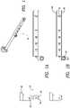
- FIG. 1is an isometric view of compression and distraction shaft A subassembly.
- FIGS. 1 A and 1 Bare side views of the shaft A subassembly.
- FIG. 2is a side view of the shaft of FIG. 1 .
- FIG. 2 Ais a top view of the shaft of FIG. 1 .
- FIG. 2 Bis a sectional view along line A-A of shaft of FIG. 1 .
- FIG. 3is an isometric view of compression and distraction shaft B subassembly.
- FIGS. 3 A and 3 Bare side views of the shaft B subassembly.
- FIG. 4is a side view of the shaft of FIG. 3 .
- FIG. 4 Ais a top view of the shaft of FIG. 3 .
- FIG. 4 Bis a sectional view along line A-A of shaft of FIG. 3 .
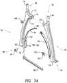
- FIG. 5shows compression pliers engaged with compression distraction shafts.
- FIG. 5 Aalso shows compression pliers engaged with compression distraction shafts.
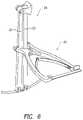
- FIG. 6shows distraction pliers engaged with compression distraction shafts.
- FIG. 6 Aalso shows distraction pliers engaged with compression distraction shafts.
- FIG. 7is an assembly drawing showing a distraction pliers assembly.
- FIG. 7 Ashows details of the distraction pliers assembly of FIG. 7 .
- FIG. 8is an assembly drawing of a compression pliers assembly.
- FIG. 8 Ashows details of the compression pliers assembly of FIG. 8 .
- FIGS. 1 , 1 A and 1 Bshow a compression and distraction shaft A assembly 20 .
- FIGS. 3 , 3 A and 3 Bshow a compression and distraction shaft B assembly 22 .
- a further assembly of the shaft A assembly 20 and shaft B assembly 22forms a compression and distraction shaft assembly 24 seen in FIGS. 5 , 5 A, 6 and 6 A .
- Assembly 20includes a shaft 26 .
- FIG. 2shows the details of construction of shaft 26 .
- Shaft 26has two long plates 28 attached to it in diametrically opposed location. One end of each of the plates 28 overhangs from the first end 30 of shaft 26 .
- the overhanging portionsare located opposite each other and have an arcuate shape at the very tip. The arcuate shape allows shaft 26 to lay over a rod that may be implanted on the vertebrae.
- a tab 32is attached in approximately middle of shaft 26 .
- Tab 32has a bore 34 .
- Bore 34has an hourglass shape along its central axis.
- a second end 36 of shaft 26is on the opposing side from end 30 .
- a fulcrum 38is attached at second end 36 .
- the means for attaching fulcrum 38may be a bore 40 formed in shaft 26 and bore 42 formed in fulcrum 38 with a pin driven through bores 40 and 42 to connect fulcrum 38 to shaft 26 .
- Assembly 22includes a shaft 44 .
- FIGS. 4 , 4 A and 4 Bshow the details of construction of shaft 44 .
- Shaft 44has a first end 46 and a second end 48 .
- First end 46is similar in construction to first end 30 of shaft 26 .
- Shaft 44has two long plates 50 attached to it in diametrically opposed location. One end of each of the plates 50 overhangs from the first end 46 of shaft 44 .
- the overhanging portionsare located opposite each other and have an arcuate shape at the very tip. The arcuate shape allows shaft 44 to lay over a rod that may be implanted on a vertebrae.
- a tab 52is attached in approximately middle of shaft 44 .
- Tab 52has a bore 54 .
- Bore 54has an hourglass shape along its central axis.
- a ball 56is formed at second end 48 .
- Ball 56mates with fulcrum 38 to form a polyaxial fulcrum point.
- FIGS. 7 and 7 Ashow distraction pliers 60 .
- Distraction pliers 60have a first handle 62 and a second handle 64 .
- First handle 62has a tip end 66 and a ratchet end 68 .
- First handle 62has an elongate shape with a cylindrical tip 70 formed at tip end 66 .
- At a distance below tip end 66two tabs 72 and 74 extend from the body of first handle 62 .
- Tabs 72 and 74are parallel to each other and have a bore 75 formed through them.
- the handle end opposing tip end 66also has two tabs 76 and 78 extend from the body of first handle 62 .
- a bore 80is formed through tabs 76 and 78 .
- a screw hole 82is formed at a distance from the ratchet end and above tabs 76 and 78 .
- a leaf spring 84is attached to first handle 62 by inserting a screw 86 in a hole in leaf spring 84 and threading screw 86 in screw hole 82 .
- Leaf spring 82has a far end that projects away from first handle 62 . The far end has a notch 88 formed at its tip.
- a ratchet 89is attached to ratchet end 68 of the first handle 62 .
- the ratchet 89has a bore 91 that aligns with bore 80 in tabs 76 and 78 .
- a pin 93is driven through bores 80 and 91 to attach ratchet 89 to first handle 62 .
- Ratchet 89has triangular projections formed on its surface.
- Second handle 64has a tip end 92 and a ratchet end 94 .
- Second handle 64has an elongate shape with a cylindrical tip 90 formed at tip end 92 .
- a tab 96extends from the body of second handle 64 .
- Tab 96has a bore 98 formed through it.
- a leaf spring 100is attached to second handle 64 .
- Second handle 64has two screw holes (not shown) formed above the ratchet end 94 .
- Leaf spring 100is attached to second handle 64 by threading two screws 102 and 104 via two holes in leaf spring 100 and into the screw holes in second handle 64 .
- Leaf spring 100has a far end that projects away from first handle 64 .
- Leaf spring 100has notch 108 formed at its tip.
- Notch 108engages notch 88 thereby engaging leaf springs 84 and 100 .
- leaf springs 84 and 100keep the distraction pliers biased in a closed position.
- a tooth 106is formed at the tip of ratchet end 94 .
- First handle 62 and second handle 64are rotatably joined together by aligning bores 75 and 80 and inserting a screw 108 through them.
- cylindrical tips 70 and 90are inserted in hourglass-shaped bores 34 and 54 and first handle 62 and second handle 64 pressed together.
- first handle 62 and the second handle 64are pressed together, the cylindrical tip 70 and 90 are moved away from each other. This results in distraction of the vertebrae that are connected to the arcuate-shaped end of the shaft A assembly 20 and shaft B assembly 22 .
- the connection between the arcuate end of the shaft assemblies 20 and 22 and the vertebraemay be made in any known manner.
- each of the shaft assemblies 20 and 22may be connected to a cup of a pedicle screw mounted on the vertebra via a latch or a threaded connection.
- first handle 62 and second handle 64are pressed to impart an appropriate amount of distraction to the vertebrae, they are locked in this position. Tooth 106 engages ratchet 89 to lock first handle 62 and second handle 64 in their pressed position, thereby holding the vertebrae in a distracted position while the surgeon fixes a rod in the pedicle screws.
- FIGS. 8 and 8 Ashow compression pliers 110 .
- Compression pliers 110have a third handle 112 and a fourth handle 114 .
- Third handle 112has a tip end 116 and a ratchet end 118 .
- a cylindrical tip 120is formed at tip end 116 .
- a hole 122is formed in the body of third handle 112 below tip end 116 .
- the end of third handle 112 opposing tip end 116has two tabs 124 and 126 .
- a bore 128is formed through tabs 124 and 126 .
- a screw hole 130is formed in body of third handle 112 above tabs 124 and 126 .
- a leaf spring 132is attached to third handle 112 by inserting a screw 134 in a hole 136 formed in leaf spring 132 and threading the screw in the hole 130 .
- Leaf spring 132has a far end that projects away from third handle 112 .
- the far endhas a notch 138 formed at its tip.
- a ratchet 140is attached to ratchet end 118 of the third handle 112 .
- the ratchet 140has a bore 142 that aligns with bore 128 in tabs 124 and 126 .
- a pin 144is driven through bores 128 and 142 to attach ratchet 140 to third handle 112 .
- Ratchet 140has triangular projections formed on its surface.
- Fourth handle 114has a tip end 146 and a ratchet end 148 .
- Fourth handle 114has a cylindrical tip 150 formed at tip end 146 .
- a bore 152is formed in the body of third handle 114 .
- a leaf spring 154is attached to fourth handle 114 .
- Fourth handle 114has two screw holes (not shown) formed above the ratchet end 148 .
- Leaf spring 154is attached to fourth handle 114 by threading two screws 156 and 158 via two holes in leaf spring 154 and into the screw holes in fourth handle 114 .
- Leaf spring 154has a far end that projects away from fourth handle 114 .
- Leaf spring 154has notch 160 formed at its tip.
- Notch 160engages notch 138 thereby engaging leaf springs 154 and 132 .
- leaf springs 132 and 154keep the compression pliers biased in an open position.
- a tooth 162is formed at the tip of ratchet end 148 .
- Third handle 112 and fourth handle 114are rotatably joined together by aligning bores 122 and 152 and inserting a screw 164 through them.
- cylindrical tips 120 and 150are inserted in hourglass-shaped bores 34 and 54 and third handle 112 and fourth handle 114 pressed together.
- cylindrical tips 120 and 150are moved towards each other. This results in compression of the vertebrae that are connected to the arcuate-shaped end of the shaft assembly 20 and shaft assembly 22 .
- the connection between the arcuate end of the shaft assemblies 20 and 22 and the vertebraemay be made in any known manner.
- each of the shaft assemblies 20 and 22may be connected to a cup of a pedicle screw mounted on the vertebrae via a latch or a threaded connection.
- third handle 112 and fourth handle 114are pressed to impart an appropriate amount of compression to the vertebrae, they are locked in this position. Tooth 162 engages ratchet 140 to lock third handle 112 and fourth handle 114 in their pressed position, thereby holding the vertebrae in compressed position while the surgeon fixes a rod in the pedicle screws.
- the compression and distraction pliersmay also be used with compression distraction shafts that are not attached to each other. These shafts can be attached rigidly to the tips of the compression or distraction pliers and impart compression or distraction to the bones.
- the compression and distraction systemmay also be used with minimally invasive surgery as described, for example, in commonly assigned U.S. Patent Application Publication No. 2007/0233079, entitled “Rod Contouring Apparatus And Method For Percutaneous Pedicle Screw Extension,” which is incorporated herein by reference in its entirety.
Landscapes
- Health & Medical Sciences (AREA)
- Orthopedic Medicine & Surgery (AREA)
- Neurology (AREA)
- Life Sciences & Earth Sciences (AREA)
- Surgery (AREA)
- Heart & Thoracic Surgery (AREA)
- Engineering & Computer Science (AREA)
- Biomedical Technology (AREA)
- Nuclear Medicine, Radiotherapy & Molecular Imaging (AREA)
- Medical Informatics (AREA)
- Molecular Biology (AREA)
- Animal Behavior & Ethology (AREA)
- General Health & Medical Sciences (AREA)
- Public Health (AREA)
- Veterinary Medicine (AREA)
- Surgical Instruments (AREA)
- Prostheses (AREA)
Abstract
Description
Claims (21)
Priority Applications (2)
| Application Number | Priority Date | Filing Date | Title |
|---|---|---|---|
| US16/662,515US11523810B2 (en) | 2006-09-25 | 2019-10-24 | Percutaneous compression and distraction system |
| US17/990,033US12156646B2 (en) | 2006-09-25 | 2022-11-18 | Percutaneous compression and distraction system |
Applications Claiming Priority (7)
| Application Number | Priority Date | Filing Date | Title |
|---|---|---|---|
| US84717406P | 2006-09-25 | 2006-09-25 | |
| US11/904,030US8157809B2 (en) | 2006-09-25 | 2007-09-25 | Percutaneous compression and distraction system |
| US13/419,919US8506574B2 (en) | 2006-09-25 | 2012-03-14 | Percutaneous compression and distraction system |
| US13/942,071US8915925B2 (en) | 2006-09-25 | 2013-07-15 | Percutaneous compression and distraction system |
| US14/547,482US9345463B2 (en) | 2006-09-25 | 2014-11-19 | Percutaneous compression and distraction system |
| US15/141,238US10470752B2 (en) | 2006-09-25 | 2016-04-28 | Percutaneous compression and distraction system |
| US16/662,515US11523810B2 (en) | 2006-09-25 | 2019-10-24 | Percutaneous compression and distraction system |
Related Parent Applications (1)
| Application Number | Title | Priority Date | Filing Date |
|---|---|---|---|
| US15/141,238ContinuationUS10470752B2 (en) | 2006-09-25 | 2016-04-28 | Percutaneous compression and distraction system |
Related Child Applications (1)
| Application Number | Title | Priority Date | Filing Date |
|---|---|---|---|
| US17/990,033ContinuationUS12156646B2 (en) | 2006-09-25 | 2022-11-18 | Percutaneous compression and distraction system |
Publications (2)
| Publication Number | Publication Date |
|---|---|
| US20200121310A1 US20200121310A1 (en) | 2020-04-23 |
| US11523810B2true US11523810B2 (en) | 2022-12-13 |
Family
ID=38869782
Family Applications (7)
| Application Number | Title | Priority Date | Filing Date |
|---|---|---|---|
| US11/904,030Active2030-10-31US8157809B2 (en) | 2006-09-25 | 2007-09-25 | Percutaneous compression and distraction system |
| US13/419,919Expired - Fee RelatedUS8506574B2 (en) | 2006-09-25 | 2012-03-14 | Percutaneous compression and distraction system |
| US13/942,071ActiveUS8915925B2 (en) | 2006-09-25 | 2013-07-15 | Percutaneous compression and distraction system |
| US14/547,482ActiveUS9345463B2 (en) | 2006-09-25 | 2014-11-19 | Percutaneous compression and distraction system |
| US15/141,238Active2029-07-14US10470752B2 (en) | 2006-09-25 | 2016-04-28 | Percutaneous compression and distraction system |
| US16/662,515Active2029-03-03US11523810B2 (en) | 2006-09-25 | 2019-10-24 | Percutaneous compression and distraction system |
| US17/990,033Active2027-12-02US12156646B2 (en) | 2006-09-25 | 2022-11-18 | Percutaneous compression and distraction system |
Family Applications Before (5)
| Application Number | Title | Priority Date | Filing Date |
|---|---|---|---|
| US11/904,030Active2030-10-31US8157809B2 (en) | 2006-09-25 | 2007-09-25 | Percutaneous compression and distraction system |
| US13/419,919Expired - Fee RelatedUS8506574B2 (en) | 2006-09-25 | 2012-03-14 | Percutaneous compression and distraction system |
| US13/942,071ActiveUS8915925B2 (en) | 2006-09-25 | 2013-07-15 | Percutaneous compression and distraction system |
| US14/547,482ActiveUS9345463B2 (en) | 2006-09-25 | 2014-11-19 | Percutaneous compression and distraction system |
| US15/141,238Active2029-07-14US10470752B2 (en) | 2006-09-25 | 2016-04-28 | Percutaneous compression and distraction system |
Family Applications After (1)
| Application Number | Title | Priority Date | Filing Date |
|---|---|---|---|
| US17/990,033Active2027-12-02US12156646B2 (en) | 2006-09-25 | 2022-11-18 | Percutaneous compression and distraction system |
Country Status (4)
| Country | Link |
|---|---|
| US (7) | US8157809B2 (en) |
| EP (1) | EP2066242B1 (en) |
| DE (1) | DE602007014385D1 (en) |
| WO (1) | WO2008039447A1 (en) |
Families Citing this family (27)
| Publication number | Priority date | Publication date | Assignee | Title |
|---|---|---|---|---|
| US7955355B2 (en) | 2003-09-24 | 2011-06-07 | Stryker Spine | Methods and devices for improving percutaneous access in minimally invasive surgeries |
| DE602007008112D1 (en) | 2006-09-25 | 2010-09-09 | Stryker Spine | ALIGNMENT CONNECTION FOR BAR CONTOURING |
| EP3009089B1 (en) | 2007-05-18 | 2017-06-21 | Stryker European Holdings I, LLC | System for direct vertebral rotation |
| US9907582B1 (en) | 2011-04-25 | 2018-03-06 | Nuvasive, Inc. | Minimally invasive spinal fixation system and related methods |
| US9125703B2 (en) | 2012-01-16 | 2015-09-08 | K2M, Inc. | Rod reducer, compressor, distractor system |
| US8951258B2 (en) | 2013-03-01 | 2015-02-10 | Warsaw Orthopedic, Inc. | Spinal correction system and method |
| CA2846149C (en) | 2013-03-14 | 2018-03-20 | Stryker Spine | Systems and methods for percutaneous spinal fusion |
| US9827020B2 (en) | 2013-03-14 | 2017-11-28 | Stryker European Holdings I, Llc | Percutaneous spinal cross link system and method |
| US9744050B1 (en) | 2013-12-06 | 2017-08-29 | Stryker European Holdings I, Llc | Compression and distraction system for percutaneous posterior spinal fusion |
| US10159579B1 (en) | 2013-12-06 | 2018-12-25 | Stryker European Holdings I, Llc | Tubular instruments for percutaneous posterior spinal fusion systems and methods |
| US9408716B1 (en) | 2013-12-06 | 2016-08-09 | Stryker European Holdings I, Llc | Percutaneous posterior spinal fusion implant construction and method |
| CA2874390C (en) | 2013-12-13 | 2018-03-06 | Stryker European Holdings I, Llc | Tissue retraction and vertebral displacement devices, systems, and methods for posterior spinal fusion |
| CN105720036A (en)* | 2014-12-03 | 2016-06-29 | 恒劲科技股份有限公司 | Packaging structure and its manufacturing method |
| CA3008161C (en) | 2014-12-09 | 2023-09-26 | John A. Heflin | Spine alignment system |
| US10194960B1 (en) | 2015-12-03 | 2019-02-05 | Nuvasive, Inc. | Spinal compression instrument and related methods |
| WO2017109540A1 (en) | 2015-12-21 | 2017-06-29 | Arcelormittal | Method for producing a high strength steel sheet having improved ductility and formability, and obtained steel sheet |
| US10617449B2 (en) | 2016-01-08 | 2020-04-14 | Stryker European Holdings I, Llc | Tap marker |
| US10779866B2 (en) | 2016-12-29 | 2020-09-22 | K2M, Inc. | Rod reducer assembly |
| US10736672B2 (en) | 2017-05-25 | 2020-08-11 | Warsaw Orthopedic, Inc. | Spinal implant system and method |
| EP3517062B1 (en)* | 2018-01-26 | 2021-03-17 | Aesculap AG | Spinal repositioning instrument and spinal repositioning system |
| US10285742B1 (en) | 2018-06-22 | 2019-05-14 | Avanti Orthopaedics Llc | Bone manipulator system and method |
| EP3669801B1 (en) | 2018-12-21 | 2024-03-06 | Stryker European Operations Limited | Tap marker with flexible extension and associated instruments |
| US11382671B2 (en) | 2019-06-25 | 2022-07-12 | Warsaw Orthopedic, Inc. | Surgical instrument and method |
| EP3838197B1 (en)* | 2019-12-18 | 2024-03-13 | Biedermann Technologies GmbH & Co. KG | Instrument for use with a bone anchoring device |
| US11350922B1 (en) | 2021-02-03 | 2022-06-07 | Warsaw Orthopedic, Inc. | Modular surgical instrument system and method for shank-based retraction and distraction |
| US11432852B1 (en) | 2021-03-22 | 2022-09-06 | Warsaw Orthopedic, Inc. | Screw shank based tissue retraction |
| US12324610B2 (en) | 2021-04-28 | 2025-06-10 | Spinal Elements, Inc. | Lever reducer |
Citations (52)
| Publication number | Priority date | Publication date | Assignee | Title |
|---|---|---|---|---|
| US3997138A (en) | 1974-06-18 | 1976-12-14 | Henry Vernon Crock | Securing devices and structures |
| SU839513A1 (en) | 1979-09-14 | 1981-06-23 | Центральный Ордена Трудовогокрасного Знамени Научно-Исследова-Тельский Институт Травматологии Иортопедии Им. H.H.Приорова | Device for guiding wires |
| US4382438A (en) | 1979-09-11 | 1983-05-10 | Synthes Ag | Instrument for treatment of spinal fractures, scoliosis and the like |
| US4409968A (en) | 1980-02-04 | 1983-10-18 | Drummond Denis S | Method and apparatus for engaging a hook assembly to a spinal column |
| US4411259A (en) | 1980-02-04 | 1983-10-25 | Drummond Denis S | Apparatus for engaging a hook assembly to a spinal column |
| US4957495A (en) | 1987-04-01 | 1990-09-18 | Patrick Kluger | Device for setting the spinal column |
| US5010879A (en) | 1989-03-31 | 1991-04-30 | Tanaka Medical Instrument Manufacturing Co. | Device for correcting spinal deformities |
| US5059194A (en) | 1990-02-12 | 1991-10-22 | Michelson Gary K | Cervical distractor |
| US5167662A (en) | 1992-01-24 | 1992-12-01 | Zimmer, Inc. | Temporary clamp and inserter for a posterior midline spinal clamp |
| EP0528177A2 (en) | 1991-08-17 | 1993-02-24 | Aesculap Ag | Internal fixator for the correction of a lumbar spondyldisthesis |
| US5242443A (en) | 1991-08-15 | 1993-09-07 | Smith & Nephew Dyonics, Inc. | Percutaneous fixation of vertebrae |
| US5281223A (en) | 1992-09-21 | 1994-01-25 | Ray R Charles | Tool and method for derotating scoliotic spine |
| WO1994009726A1 (en) | 1992-10-23 | 1994-05-11 | Smith & Nephew Richards Inc. | Internal fixators |
| EP0611116A1 (en) | 1993-02-11 | 1994-08-17 | SMITH & NEPHEW RICHARDS, INC. | Spinal column retaining apparatus |
| US5478340A (en) | 1992-01-31 | 1995-12-26 | Kluger; Patrick | Vertebral column implant and repositioning instrument |
| US5487743A (en) | 1994-02-15 | 1996-01-30 | Sofamore, S.N.C. | Anterior dorso-lumbar spinal osteosynthesis instrumentation for the correction of kyphosis |
| DE29710979U1 (en) | 1997-06-24 | 1997-08-21 | Aesculap AG & Co. KG, 78532 Tuttlingen | Implant for fixing bone parts and tool for this implant |
| USRE36221E (en) | 1989-02-03 | 1999-06-01 | Breard; Francis Henri | Flexible inter-vertebral stabilizer as well as process and apparatus for determining or verifying its tension before installation on the spinal column |
| US6090113A (en) | 1996-12-27 | 2000-07-18 | Stryker France S.A. | Adjustable osteosynthesis system of the rachis |
| US6123707A (en) | 1999-01-13 | 2000-09-26 | Spinal Concepts, Inc. | Reduction instrument |
| US6146386A (en) | 1999-02-04 | 2000-11-14 | Sdgi Holdings, Inc. | Cable operated bone anchor compressor |
| WO2001041681A1 (en) | 1999-12-10 | 2001-06-14 | Nuvasive, Inc. | Facet screw and bone allograft intervertebral support and fusion system |
| DE10027988A1 (en) | 2000-06-06 | 2002-01-10 | Arkadiusz Kosmala | Appliance for percutaneous insertion of connection of pedicle screws has two arms of equal length with transverse connection, circular arm and circular support, |
| US6506151B2 (en) | 1998-04-09 | 2003-01-14 | Sdgi Holdings, Inc. | Method and instrumentation for posterior interbody fusion |
| US6530929B1 (en) | 1999-10-20 | 2003-03-11 | Sdgi Holdings, Inc. | Instruments for stabilization of bony structures |
| US20030055430A1 (en) | 2001-09-14 | 2003-03-20 | Kim Kee D. | System and method for fusing spinal vertebrae |
| US20030073998A1 (en) | 2000-08-01 | 2003-04-17 | Endius Incorporated | Method of securing vertebrae |
| US6616666B1 (en) | 1997-02-11 | 2003-09-09 | Gary K. Michelson | Apparatus for compressing a spinal disc space disposed between two adjacent vertebral bodies of a cervical spine |
| US6616667B1 (en) | 1999-11-25 | 2003-09-09 | Sulzer Orthopedics, Ltd. | Surgical instrument for tensioning a cable-like tensioning element |
| US20030187436A1 (en) | 1999-07-01 | 2003-10-02 | Ciaran Bolger | Interbody spinal stabilization cage and spinal stabilization method |
| US20040034351A1 (en) | 2002-08-14 | 2004-02-19 | Sherman Michael C. | Techniques for spinal surgery and attaching constructs to vertebral elements |
| WO2004021899A1 (en) | 2002-09-05 | 2004-03-18 | Endius Incorporated | System and methods for performing minimally-invasive surgical procedures |
| WO2004041100A1 (en) | 2002-10-30 | 2004-05-21 | Spinal Concepts, Inc. | Spinal stabilization system insertion and methods |
| US20040147928A1 (en) | 2002-10-30 | 2004-07-29 | Landry Michael E. | Spinal stabilization system using flexible members |
| WO2004080318A1 (en) | 2003-03-10 | 2004-09-23 | Sdgi Holdings Inc. | Posterior pedicle screw and plate system and methods |
| US20040215190A1 (en) | 2003-04-25 | 2004-10-28 | Nguyen Thanh V. | System and method for minimally invasive posterior fixation |
| US20040260287A1 (en) | 2001-03-26 | 2004-12-23 | Nuvasive, Inc. | Spinal alignment system and related methods |
| US20050010221A1 (en) | 2003-07-07 | 2005-01-13 | Dalton Brian E. | Spinal stabilization implant and method of application |
| US20050010220A1 (en) | 2003-04-24 | 2005-01-13 | Simon Casutt | Instrument system for pedicle screws |
| WO2005018466A2 (en) | 2003-08-26 | 2005-03-03 | Endius, Inc. | Access systems and methods for minimally invasive surgery |
| WO2005023123A1 (en) | 2003-09-09 | 2005-03-17 | Endius, Inc. | Apparatuses and methods for treating the spine through an access device |
| US20050070917A1 (en) | 2003-09-29 | 2005-03-31 | Justis Jeff R. | Instruments and methods for securing a connecting element along a bony segment |
| WO2005032358A2 (en) | 2003-10-02 | 2005-04-14 | Endius, Inc. | Methods, systems and apparatuses for performing minimally invasive spinal procedures |
| US20050090822A1 (en) | 2003-10-24 | 2005-04-28 | Dipoto Gene | Methods and apparatus for stabilizing the spine through an access device |
| US20050090833A1 (en) | 2003-10-24 | 2005-04-28 | Dipoto Gene | Methods and apparatuses for fixation of the spine through an access device |
| US20050131421A1 (en) | 2003-12-16 | 2005-06-16 | Anderson David G. | Methods and devices for minimally invasive spinal fixation element placement |
| US20050131422A1 (en) | 2003-12-16 | 2005-06-16 | Anderson David G. | Methods and devices for spinal fixation element placement |
| WO2005060534A2 (en) | 2003-12-16 | 2005-07-07 | Depuy Spine, Inc. | Methods and devices for minimally invasive spinal fixation element placement |
| US20050245928A1 (en) | 2004-05-03 | 2005-11-03 | Innovative Spinal Technologies | System and method for displacement of bony structures |
| WO2006060430A1 (en) | 2004-12-02 | 2006-06-08 | Abbott Laboratories | Instruments and methods for adjusting separation distance of vertebral bodies with a minimally invasive spinal stabilization procedure |
| US20060264934A1 (en) | 2005-05-18 | 2006-11-23 | Medicinelodge, Inc. | System and method for orthopedic implant configuration |
| US8894655B2 (en) | 2006-02-06 | 2014-11-25 | Stryker Spine | Rod contouring apparatus and method for percutaneous pedicle screw extension |
- 2007
- 2007-09-25USUS11/904,030patent/US8157809B2/enactiveActive
- 2007-09-25WOPCT/US2007/020660patent/WO2008039447A1/enactiveApplication Filing
- 2007-09-25EPEP07838793Apatent/EP2066242B1/enactiveActive
- 2007-09-25DEDE602007014385Tpatent/DE602007014385D1/enactiveActive
- 2012
- 2012-03-14USUS13/419,919patent/US8506574B2/ennot_activeExpired - Fee Related
- 2013
- 2013-07-15USUS13/942,071patent/US8915925B2/enactiveActive
- 2014
- 2014-11-19USUS14/547,482patent/US9345463B2/enactiveActive
- 2016
- 2016-04-28USUS15/141,238patent/US10470752B2/enactiveActive
- 2019
- 2019-10-24USUS16/662,515patent/US11523810B2/enactiveActive
- 2022
- 2022-11-18USUS17/990,033patent/US12156646B2/enactiveActive
Patent Citations (71)
| Publication number | Priority date | Publication date | Assignee | Title |
|---|---|---|---|---|
| US3997138A (en) | 1974-06-18 | 1976-12-14 | Henry Vernon Crock | Securing devices and structures |
| US4382438A (en) | 1979-09-11 | 1983-05-10 | Synthes Ag | Instrument for treatment of spinal fractures, scoliosis and the like |
| SU839513A1 (en) | 1979-09-14 | 1981-06-23 | Центральный Ордена Трудовогокрасного Знамени Научно-Исследова-Тельский Институт Травматологии Иортопедии Им. H.H.Приорова | Device for guiding wires |
| US4409968A (en) | 1980-02-04 | 1983-10-18 | Drummond Denis S | Method and apparatus for engaging a hook assembly to a spinal column |
| US4411259A (en) | 1980-02-04 | 1983-10-25 | Drummond Denis S | Apparatus for engaging a hook assembly to a spinal column |
| US4957495A (en) | 1987-04-01 | 1990-09-18 | Patrick Kluger | Device for setting the spinal column |
| USRE36221E (en) | 1989-02-03 | 1999-06-01 | Breard; Francis Henri | Flexible inter-vertebral stabilizer as well as process and apparatus for determining or verifying its tension before installation on the spinal column |
| US5010879A (en) | 1989-03-31 | 1991-04-30 | Tanaka Medical Instrument Manufacturing Co. | Device for correcting spinal deformities |
| US5059194A (en) | 1990-02-12 | 1991-10-22 | Michelson Gary K | Cervical distractor |
| US5242443A (en) | 1991-08-15 | 1993-09-07 | Smith & Nephew Dyonics, Inc. | Percutaneous fixation of vertebrae |
| EP0528177A2 (en) | 1991-08-17 | 1993-02-24 | Aesculap Ag | Internal fixator for the correction of a lumbar spondyldisthesis |
| US5167662A (en) | 1992-01-24 | 1992-12-01 | Zimmer, Inc. | Temporary clamp and inserter for a posterior midline spinal clamp |
| US5478340A (en) | 1992-01-31 | 1995-12-26 | Kluger; Patrick | Vertebral column implant and repositioning instrument |
| US5281223A (en) | 1992-09-21 | 1994-01-25 | Ray R Charles | Tool and method for derotating scoliotic spine |
| US5385565A (en) | 1992-09-21 | 1995-01-31 | Danek Medical, Inc. | Tool and method for derotating scoliotic spine |
| EP0665731A1 (en) | 1992-10-23 | 1995-08-09 | Smith & Nephew, Inc. | Internal fixators |
| WO1994009726A1 (en) | 1992-10-23 | 1994-05-11 | Smith & Nephew Richards Inc. | Internal fixators |
| EP0611116A1 (en) | 1993-02-11 | 1994-08-17 | SMITH & NEPHEW RICHARDS, INC. | Spinal column retaining apparatus |
| US5487743A (en) | 1994-02-15 | 1996-01-30 | Sofamore, S.N.C. | Anterior dorso-lumbar spinal osteosynthesis instrumentation for the correction of kyphosis |
| US5591167A (en) | 1994-02-15 | 1997-01-07 | Sofamor, S.N.C. | Anterior dorso-lumbar spinal osteosynthesis instrumentation for the correction of kyphosis |
| US6090113A (en) | 1996-12-27 | 2000-07-18 | Stryker France S.A. | Adjustable osteosynthesis system of the rachis |
| US20050038436A1 (en) | 1997-02-11 | 2005-02-17 | Michelson Gary K. | System and method for stabilizing a portion of the spine |
| US6712818B1 (en) | 1997-02-11 | 2004-03-30 | Gary K. Michelson | Method for connecting adjacent vertebral bodies of a human spine with a plating system |
| US6616666B1 (en) | 1997-02-11 | 2003-09-09 | Gary K. Michelson | Apparatus for compressing a spinal disc space disposed between two adjacent vertebral bodies of a cervical spine |
| DE29710979U1 (en) | 1997-06-24 | 1997-08-21 | Aesculap AG & Co. KG, 78532 Tuttlingen | Implant for fixing bone parts and tool for this implant |
| DE19726754A1 (en) | 1997-06-24 | 1999-02-04 | Aesculap Ag & Co Kg | Implant for fixing parts of bones in particular at spine |
| US6506151B2 (en) | 1998-04-09 | 2003-01-14 | Sdgi Holdings, Inc. | Method and instrumentation for posterior interbody fusion |
| US6123707A (en) | 1999-01-13 | 2000-09-26 | Spinal Concepts, Inc. | Reduction instrument |
| US6146386A (en) | 1999-02-04 | 2000-11-14 | Sdgi Holdings, Inc. | Cable operated bone anchor compressor |
| US20030187436A1 (en) | 1999-07-01 | 2003-10-02 | Ciaran Bolger | Interbody spinal stabilization cage and spinal stabilization method |
| US20050021031A1 (en) | 1999-10-20 | 2005-01-27 | Foley Kevin T. | Instruments and methods for stabilization of bony structures |
| US7011660B2 (en) | 1999-10-20 | 2006-03-14 | Sdgi Holdings, Inc. | Instruments and methods for stabilization of bony structures |
| US7008422B2 (en) | 1999-10-20 | 2006-03-07 | Sdgi Holdings, Inc. | Instruments and methods for stabilization of bony structures |
| US20060111714A1 (en) | 1999-10-20 | 2006-05-25 | Foley Kevin T | Instruments and methods for stabilization of bony structures |
| US6530929B1 (en) | 1999-10-20 | 2003-03-11 | Sdgi Holdings, Inc. | Instruments for stabilization of bony structures |
| US20060200135A1 (en) | 1999-10-20 | 2006-09-07 | Sherman Michael C | Instruments and methods for stabilization of bony structures |
| US7188626B2 (en) | 1999-10-20 | 2007-03-13 | Warsaw Orthopedic, Inc. | Instruments and methods for stabilization of bony structures |
| US6616667B1 (en) | 1999-11-25 | 2003-09-09 | Sulzer Orthopedics, Ltd. | Surgical instrument for tensioning a cable-like tensioning element |
| US6485518B1 (en) | 1999-12-10 | 2002-11-26 | Nuvasive | Facet screw and bone allograft intervertebral support and fusion system |
| WO2001041681A1 (en) | 1999-12-10 | 2001-06-14 | Nuvasive, Inc. | Facet screw and bone allograft intervertebral support and fusion system |
| DE10027988A1 (en) | 2000-06-06 | 2002-01-10 | Arkadiusz Kosmala | Appliance for percutaneous insertion of connection of pedicle screws has two arms of equal length with transverse connection, circular arm and circular support, |
| US20030073998A1 (en) | 2000-08-01 | 2003-04-17 | Endius Incorporated | Method of securing vertebrae |
| US20050021030A1 (en) | 2000-08-01 | 2005-01-27 | Endius Incorporated | Method of securing vertebrae |
| US20040260287A1 (en) | 2001-03-26 | 2004-12-23 | Nuvasive, Inc. | Spinal alignment system and related methods |
| US20030055430A1 (en) | 2001-09-14 | 2003-03-20 | Kim Kee D. | System and method for fusing spinal vertebrae |
| US20040034351A1 (en) | 2002-08-14 | 2004-02-19 | Sherman Michael C. | Techniques for spinal surgery and attaching constructs to vertebral elements |
| WO2004021899A1 (en) | 2002-09-05 | 2004-03-18 | Endius Incorporated | System and methods for performing minimally-invasive surgical procedures |
| WO2004037074A2 (en) | 2002-10-25 | 2004-05-06 | Endius Incorporated | Method of securing vertebrae |
| US20040143265A1 (en) | 2002-10-30 | 2004-07-22 | Landry Michael E. | Spinal stabilization systems and methods using minimally invasive surgical procedures |
| WO2004041100A1 (en) | 2002-10-30 | 2004-05-21 | Spinal Concepts, Inc. | Spinal stabilization system insertion and methods |
| US20040138662A1 (en) | 2002-10-30 | 2004-07-15 | Landry Michael E. | Spinal stabilization systems and methods |
| US20040147928A1 (en) | 2002-10-30 | 2004-07-29 | Landry Michael E. | Spinal stabilization system using flexible members |
| US20040172022A1 (en) | 2002-10-30 | 2004-09-02 | Landry Michael E. | Bone fastener assembly for a spinal stabilization system |
| WO2004080318A1 (en) | 2003-03-10 | 2004-09-23 | Sdgi Holdings Inc. | Posterior pedicle screw and plate system and methods |
| US20050010220A1 (en) | 2003-04-24 | 2005-01-13 | Simon Casutt | Instrument system for pedicle screws |
| US20040215190A1 (en) | 2003-04-25 | 2004-10-28 | Nguyen Thanh V. | System and method for minimally invasive posterior fixation |
| US20050010221A1 (en) | 2003-07-07 | 2005-01-13 | Dalton Brian E. | Spinal stabilization implant and method of application |
| WO2005018466A2 (en) | 2003-08-26 | 2005-03-03 | Endius, Inc. | Access systems and methods for minimally invasive surgery |
| WO2005023123A1 (en) | 2003-09-09 | 2005-03-17 | Endius, Inc. | Apparatuses and methods for treating the spine through an access device |
| US20050070917A1 (en) | 2003-09-29 | 2005-03-31 | Justis Jeff R. | Instruments and methods for securing a connecting element along a bony segment |
| WO2005032358A2 (en) | 2003-10-02 | 2005-04-14 | Endius, Inc. | Methods, systems and apparatuses for performing minimally invasive spinal procedures |
| US20050090833A1 (en) | 2003-10-24 | 2005-04-28 | Dipoto Gene | Methods and apparatuses for fixation of the spine through an access device |
| US20050090822A1 (en) | 2003-10-24 | 2005-04-28 | Dipoto Gene | Methods and apparatus for stabilizing the spine through an access device |
| WO2005060534A2 (en) | 2003-12-16 | 2005-07-07 | Depuy Spine, Inc. | Methods and devices for minimally invasive spinal fixation element placement |
| US20050154389A1 (en) | 2003-12-16 | 2005-07-14 | Depuy Spine, Inc. | Methods and devices for minimally invasive spinal fixation element placement |
| US20050131422A1 (en) | 2003-12-16 | 2005-06-16 | Anderson David G. | Methods and devices for spinal fixation element placement |
| US20050131421A1 (en) | 2003-12-16 | 2005-06-16 | Anderson David G. | Methods and devices for minimally invasive spinal fixation element placement |
| US20050245928A1 (en) | 2004-05-03 | 2005-11-03 | Innovative Spinal Technologies | System and method for displacement of bony structures |
| WO2006060430A1 (en) | 2004-12-02 | 2006-06-08 | Abbott Laboratories | Instruments and methods for adjusting separation distance of vertebral bodies with a minimally invasive spinal stabilization procedure |
| US20060264934A1 (en) | 2005-05-18 | 2006-11-23 | Medicinelodge, Inc. | System and method for orthopedic implant configuration |
| US8894655B2 (en) | 2006-02-06 | 2014-11-25 | Stryker Spine | Rod contouring apparatus and method for percutaneous pedicle screw extension |
Non-Patent Citations (10)
| Title |
|---|
| Arnett et al., U.S. Appl. No. 11/904,029, filed Sep. 25, 2007, titled "Rod Contouring Alignment Linkage". |
| Charles Hartjen; The Atavi System, Surgical Technique Brochure. Endius, p. 1-17, undated. |
| Diapason, Surgical Texchnique Catalog, Diapasan Spinal System, Jan. 2002. |
| Fallin et al., U.S. Appl. No. 11/526,785, filed Sep. 25, 2006, titled "Rod contouring apparatus and method for percutaneous pedicle screw extension". |
| Fallin et al., U.S. Appl. No. 12/316,637, filed Dec. 15, 2008, titled "Rod contouring apparatus for percutaneous pedicle screw extension". |
| Kambin et al, "Percutaneous Posterolateral Lumbar Discectomy and Decompression with a 6.9-millimeter cannula", The Journal of Bone and Joint Surgery, pp. 822-831, Jul. 1991. |
| Kambin, Minimally Invasive Techniques in Spinal Surgery Current Practice, Neurosurgical Focus, wwwspineuniversecom, 16 pages, printed Aug. 24, 2005. |
| Leu et al., Percutaneous Fusion of the Lumbar Spine, State of the Art Reviews, vol. 6, No. 3, pp. 593-604, Sep. 1992. |
| Pathfinder; Minimally Invasive Pedicie Fixation System. Spinal Concepts Product Brochure p. 1-4, May 2003. |
| T. Wade Fallin., U.S. Appl. No. 11/178,035, filed Jul. 8, 2005, titled "System and Method for Orthopedic Implant Configuration". |
Also Published As
| Publication number | Publication date |
|---|---|
| US8506574B2 (en) | 2013-08-13 |
| EP2066242A1 (en) | 2009-06-10 |
| EP2066242B1 (en) | 2011-05-04 |
| US20200121310A1 (en) | 2020-04-23 |
| DE602007014385D1 (en) | 2011-06-16 |
| US12156646B2 (en) | 2024-12-03 |
| US20080125789A1 (en) | 2008-05-29 |
| US20120191137A1 (en) | 2012-07-26 |
| US8915925B2 (en) | 2014-12-23 |
| US9345463B2 (en) | 2016-05-24 |
| US20230082047A1 (en) | 2023-03-16 |
| US20140018860A1 (en) | 2014-01-16 |
| US20160338683A1 (en) | 2016-11-24 |
| US20150073428A1 (en) | 2015-03-12 |
| US8157809B2 (en) | 2012-04-17 |
| WO2008039447A1 (en) | 2008-04-03 |
| US10470752B2 (en) | 2019-11-12 |
Similar Documents
| Publication | Publication Date | Title |
|---|---|---|
| US12156646B2 (en) | Percutaneous compression and distraction system | |
| US11596455B2 (en) | Reduction instrument, surgical assembly including a reduction instrument and related method | |
| US8460308B2 (en) | Insertion and reduction tool for pedicle screw assembly | |
| US9387017B2 (en) | System and method for manipulating a spinal construct | |
| US9820779B2 (en) | Spinal stabilization system | |
| EP3741307B1 (en) | Soft tissue retractor | |
| US7988695B2 (en) | Articulated delivery instrument | |
| US8192438B2 (en) | Rod reducer | |
| US8105329B2 (en) | Reducing instrument for spinal surgery | |
| US8747409B2 (en) | Surgical instrument for positioning a spinal rod | |
| US20080077155A1 (en) | System and method for displacement of bony structures | |
| AU2005274115A1 (en) | Reducing instrument for spinal surgery | |
| US20230329758A1 (en) | Adjustable, modular instrument and method for spinal manipulation |
Legal Events
| Date | Code | Title | Description |
|---|---|---|---|
| FEPP | Fee payment procedure | Free format text:ENTITY STATUS SET TO UNDISCOUNTED (ORIGINAL EVENT CODE: BIG.); ENTITY STATUS OF PATENT OWNER: LARGE ENTITY | |
| AS | Assignment | Owner name:STRYKER SPINE, FRANCE Free format text:ASSIGNMENT OF ASSIGNORS INTEREST;ASSIGNORS:BUTTERS, JOSHUA A.;ARNETT, JEFFERY;REEL/FRAME:050861/0864 Effective date:20071213 Owner name:STRYKER EUROPEAN HOLDINGS I, LLC, MICHIGAN Free format text:NUNC PRO TUNC ASSIGNMENT;ASSIGNOR:STRYKER EUROPEAN HOLDINGS VI, LLC;REEL/FRAME:050874/0692 Effective date:20151008 Owner name:STRYKER EUROPEAN HOLDINGS VI, LLC, MICHIGAN Free format text:NUNC PRO TUNC ASSIGNMENT;ASSIGNOR:STRYKER SPINE;REEL/FRAME:050874/0831 Effective date:20151008 | |
| STPP | Information on status: patent application and granting procedure in general | Free format text:DOCKETED NEW CASE - READY FOR EXAMINATION | |
| AS | Assignment | Owner name:STRYKER EUROPEAN OPERATIONS HOLDINGS LLC, MICHIGAN Free format text:CHANGE OF NAME;ASSIGNOR:STRYKER EUROPEAN HOLDINGS III, LLC;REEL/FRAME:053973/0918 Effective date:20190226 Owner name:STRYKER EUROPEAN HOLDINGS III, LLC, DELAWARE Free format text:NUNC PRO TUNC ASSIGNMENT;ASSIGNOR:STRYKER EUROPEAN HOLDINGS I, LLC;REEL/FRAME:054252/0089 Effective date:20200519 | |
| STPP | Information on status: patent application and granting procedure in general | Free format text:NON FINAL ACTION MAILED | |
| STPP | Information on status: patent application and granting procedure in general | Free format text:RESPONSE TO NON-FINAL OFFICE ACTION ENTERED AND FORWARDED TO EXAMINER | |
| STPP | Information on status: patent application and granting procedure in general | Free format text:NOTICE OF ALLOWANCE MAILED -- APPLICATION RECEIVED IN OFFICE OF PUBLICATIONS | |
| STPP | Information on status: patent application and granting procedure in general | Free format text:PUBLICATIONS -- ISSUE FEE PAYMENT VERIFIED | |
| STCF | Information on status: patent grant | Free format text:PATENTED CASE | |
| AS | Assignment | Owner name:STRYKER EUROPEAN OPERATIONS HOLDINGS LLC, MICHIGAN Free format text:CHANGE OF ADDRESS;ASSIGNOR:STRYKER EUROPEAN OPERATIONS HOLDINGS LLC;REEL/FRAME:069730/0754 Effective date:20241217 | |
| AS | Assignment | Owner name:VB SPINE US OPCO LLC, DELAWARE Free format text:ASSIGNMENT OF ASSIGNORS INTEREST;ASSIGNOR:STRYKER EUROPEAN OPERATIONS HOLDINGS LLC;REEL/FRAME:071267/0099 Effective date:20250401 | |
| AS | Assignment | Owner name:ANKURA TRUST COMPANY, LLC, AS COLLATERAL AGENT, CONNECTICUT Free format text:PATENT SECURITY AGREEMENT;ASSIGNORS:K2M, INC.;VB SPINE US OPCO LLC;VB SPINE LLC;REEL/FRAME:071682/0116 Effective date:20250616 | |
| AS | Assignment | Owner name:TEXAS CAPITAL BANK, AS COLLATERAL AGENT, TEXAS Free format text:SECURITY INTEREST;ASSIGNORS:K2M, INC.;VB SPINE US OPCO LLC;REEL/FRAME:072340/0397 Effective date:20250401 |