US11523707B2 - Sequential broiling - Google Patents
Sequential broilingDownload PDFInfo
- Publication number
- US11523707B2 US11523707B2US16/120,100US201816120100AUS11523707B2US 11523707 B2US11523707 B2US 11523707B2US 201816120100 AUS201816120100 AUS 201816120100AUS 11523707 B2US11523707 B2US 11523707B2
- Authority
- US
- United States
- Prior art keywords
- heating
- power
- cooking
- zone
- cooking instrument
- Prior art date
- Legal status (The legal status is an assumption and is not a legal conclusion. Google has not performed a legal analysis and makes no representation as to the accuracy of the status listed.)
- Active, expires
Links
Images


Classifications
- A—HUMAN NECESSITIES
- A47—FURNITURE; DOMESTIC ARTICLES OR APPLIANCES; COFFEE MILLS; SPICE MILLS; SUCTION CLEANERS IN GENERAL
- A47J—KITCHEN EQUIPMENT; COFFEE MILLS; SPICE MILLS; APPARATUS FOR MAKING BEVERAGES
- A47J37/00—Baking; Roasting; Grilling; Frying
- A47J37/06—Roasters; Grills; Sandwich grills
- A47J37/067—Horizontally disposed broiling griddles
- A47J37/0676—Horizontally disposed broiling griddles electrically heated
- F—MECHANICAL ENGINEERING; LIGHTING; HEATING; WEAPONS; BLASTING
- F24—HEATING; RANGES; VENTILATING
- F24C—DOMESTIC STOVES OR RANGES ; DETAILS OF DOMESTIC STOVES OR RANGES, OF GENERAL APPLICATION
- F24C7/00—Stoves or ranges heated by electric energy
- F24C7/06—Arrangement or mounting of electric heating elements
- F24C7/067—Arrangement or mounting of electric heating elements on ranges
- F—MECHANICAL ENGINEERING; LIGHTING; HEATING; WEAPONS; BLASTING
- F24—HEATING; RANGES; VENTILATING
- F24C—DOMESTIC STOVES OR RANGES ; DETAILS OF DOMESTIC STOVES OR RANGES, OF GENERAL APPLICATION
- F24C7/00—Stoves or ranges heated by electric energy
- F24C7/08—Arrangement or mounting of control or safety devices
- F24C7/087—Arrangement or mounting of control or safety devices of electric circuits regulating heat
- H—ELECTRICITY
- H05—ELECTRIC TECHNIQUES NOT OTHERWISE PROVIDED FOR
- H05B—ELECTRIC HEATING; ELECTRIC LIGHT SOURCES NOT OTHERWISE PROVIDED FOR; CIRCUIT ARRANGEMENTS FOR ELECTRIC LIGHT SOURCES, IN GENERAL
- H05B6/00—Heating by electric, magnetic or electromagnetic fields
- H05B6/02—Induction heating
- H05B6/10—Induction heating apparatus, other than furnaces, for specific applications
- H05B6/12—Cooking devices
- H05B6/1209—Cooking devices induction cooking plates or the like and devices to be used in combination with them
- H05B6/1236—Cooking devices induction cooking plates or the like and devices to be used in combination with them adapted to induce current in a coil to supply power to a device and electrical heating devices powered in this way
Definitions
- Various embodimentsrelate to cooking instruments, such as ovens.
- FIG. 1is a structural diagram of a perspective view of a cooking instrument, in accordance with various embodiments.
- FIG. 2is a block diagram illustrating physical components of a cooking instrument, in accordance with various embodiments.
- FIG. 3is a block diagram illustrating functional components of a cooking instrument, in accordance with various embodiments.
- FIG. 4is a flowchart illustrating a method of operating a cooking instrument to cook food, in accordance with various embodiments.
- FIG. 5 Ais a cross-sectional front view of a first example of a cooking instrument, in accordance with various embodiments.
- FIG. 5 Bis a cross-sectional top view of the cooking instrument of FIG. 5 A along lines A-A′, in accordance with various embodiments.
- FIG. 5 Cis a cross-sectional top view of the cooking instrument of FIG. 5 A along lines B-B′, in accordance with various embodiments.
- FIG. 5 Dis a cross-sectional top view of the cooking instrument of FIG. 5 A along lines C-C′, in accordance with various embodiments.
- FIG. 6is a cross-sectional front view of a second example of a cooking instrument, in accordance with various embodiments.
- FIG. 7is a circuit diagram of a heating system of a cooking instrument, in accordance with various embodiments.
- FIG. 8is a flow chart illustrating a method of operating a cooking instrument, in accordance with various embodiments.
- FIG. 9is a flowchart illustrating a method of operating a cooking appliance to cook an edible substance in different modes, in accordance with various embodiments.
- Conventional cooking instrumentssuch as a convection oven, aims to cook food evenly. These conventional cooking instruments achieve even cooking by avoiding directional heating. As a result, the exterior surface of a target food substance would be cooked evenly by heating elements of a conventional cooking instrument.
- omnidirectional heatingrequires a higher power consumption compared to directional heating.
- the speed in which a conventional cooking instrument can cook foodis often capped by how much power the conventional instrument can draw from a household outlet without triggering the circuit breaker.
- a cooking instrumentis configured to sequentially focus its total available power of its heating system (“total transferable power”) toward respective subsections of the exterior surface of the target food substance.
- total transferable powertotal available power of its heating system
- the cooking instrumentcan include: a cooking chamber (e.g., the chamber 102 ); a power component (e.g., relay, an inverter, a converter, or any combination thereof, such as the power source 202 ); a heating system (e.g., the heating elements 114 ); and a control system (e.g., the computing device 206 ).
- the power componentcan be adapted to draw from an alternating current (AC) power source (e.g., alternating current power line 710 ) substantially at a maximum limit of the power source and convert and/or provide the drawn AC power to a maximum transferable power to an infrared-based heating system.
- ACalternating current
- the power componentcan be a variable DC power component.
- the power componentcan be a relay that provides the external AC power directly to the heating elements of the heating system.
- the power componentcan be configured to supply power at a predefined power level that is a maximum amount capable of being drawn from a power source without triggering a circuit breaker of the power source.
- the maximum transferable poweris the drawn AC power reduced by power conversion/relay inefficiency and the power draw of other components of the cooking instrument during each step of a heating sequence.
- the heating systemcan emit wireless waves that directly transfer heat to food. These wireless waves can include waves with peak wavelengths in the infrared spectrum.
- the heating systemcan be referred to as the “infrared-based heating system.
- the infrared-based heating systemcan include: multiple heating elements on a side of the cooking chamber; and one or more heat element drivers (e.g., filament drivers 224 ) for the multiple heating elements.
- each of the one or more heat element driverscorresponds to a single one of the multiple heating elements.
- each of the one or more heat element driverscorresponds to more than one of the multiple heating elements.
- the control systemis configured to drive subsets of the multiple heating elements in sequence. In each step of the sequence, the control system is configured to drive each subset utilizing the maximum transferable power. In one example, the maximum limit is 1500 W of continuous draw and 1800 W of temporary draw. In some cases, each of the subsets is a single heating element. In other cases, each subset includes more than one heating element. In some examples, the subsets have at least one different heating element from one another.
- the power componenthas the hardware capability of drawing power that is more than the maximum limit from the AC power source but for that it is configured with a feedback loop to prevent drawing more than the maximum limit.
- the power component and the heating elementswhen subjected to a compliant AC power source, would stabilize at the maximum transferable power because it would have single impedance/resistance level and characteristic power load that prevent further power draw.
- the power componentcan be referred to as a power supply.
- the control systemis configured to utilize a feedback control loop to achieve even heating of at least one side of food in the cooking chamber after completion of the sequence.
- the control systemis configured to dynamically adjust duration and/or intensity of a step or heating intensity of a subset of the heating elements in the sequence based on a sensor input.
- the control systemcan be configured to monitor power consumption of the heating system as an input to the feedback control loop.
- the control systemcan ensure that power consumption of each subset of the heating elements is substantially equal amongst steps in the sequence.
- the control systemcan configure the sequence to prevent no more power draw than the maximum transferable power.
- the cooking instrumentincludes an image sensor.
- the control systemis configured to analyze an image from the image sensor to produce an input to the feedback control loop such that the control system ensures to continue heating with each subset of the heating elements until the target food is visually equivalent in browning level as the food targeted by another subset.
- the cooking instrumentincludes one or more temperature sensors configured to monitor temperature of the food respectively targeted by the subsets.
- the control systemis configured to compare the temperature of the targeted food against a preset temperature and utilize the detected temperature as an input to the feedback control loop such that the control system ensures to continue heating with each subset of the heating elements until the target food is reaches the predetermined temperature.
- control systemis configured to reduce said heating between sequential steps in the sequence for a predetermined constant duration.
- a cooking instrumentcomprising: a heating system with multiple heating elements; at least one heating element driver; a power component capable of providing power (e.g., variable power) to a heating system up to a maximum limit; and a controller configured to select a heating sequence to operate the heating system.
- the at least one heating element driveris configured to be able to, at a given step of the heating sequence, divert the provided power at the maximum limit (e.g., equally or unequally) to the heating elements or to converge the provided power at the maximum limit to only a subset of the multiple heating elements.
- the cooking instrumentcan include an input interface (e.g., the input component 234 ).
- the cooking instrumentcan also include a cooking chamber.
- the at least one heating element driveris configured by the controller to heat, according to a digital recipe received via the input interface, food in the cooking chamber.
- the input interfacecan be a user interface (e.g., one or more buttons, a touch screen, a microphone, or any combination thereof) or a wireless communication interface that communicates with another device.
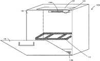
- FIG. 1is a structural diagram of a perspective view of a cooking instrument 100 , in accordance with various embodiments.
- the cooking instrument 100can include a chamber 102 having a door 106 .
- At least one cooking platform 110is disposed inside the chamber 102 .
- the cooking platform 110can be a tray, a rack, or any combination thereof.
- the chamber 102can be lined with one or more heating elements 114 (e.g., a heating element 114 A, a heating element 114 B, etc., collectively as the “heating elements 114 ”).
- Each of heating elements 114can include a wavelength controllable filament assembly.
- the wavelength controllable filament assemblyis capable of independently adjusting an emission frequency/wavelength, emission power, and/or emission signal pattern in response to a command from a computing device (not shown) of the cooking instrument 100 .
- the chamber 102is windowless. That is, the chamber 102 , including the door 106 , is entirely enclosed without any transparent (and/or semitransparent) parts when the door 106 is closed.
- the chamber 102can be sealed within a metal enclosure (e.g., with thermal insulation from/to the outside of the chamber 102 ) when the door 106 is closed.
- a camera 118can be attached to an interior of the chamber 102 . In some embodiments, the camera 118 is attached to the door 106 . For example, the camera 118 can face inward toward the interior of the chamber 102 when the door 106 is closed and upward when the door 106 is opened as illustrated.
- the camera 118is installed on the ceiling (e.g., top interior surface) of the chamber 102 .
- the camera 118can be attached to the door 106 or proximate (e.g., within three inches) to the door 106 on the ceiling of the chamber 102 to enable easy cleaning, convenient scanning of labels, privacy, heat damage avoidance, etc.
- the heating elements 114include one or more wavelength-controllable filament assemblies at one or more locations in the chamber.
- each of the one or more wavelength-controllable filament assembliesis capable of independently adjusting its emission frequency (e.g., peak emission frequency) and/or its emission power.
- the peak emission frequency of the wavelength-controllable filament assembliescan be tuned within a broad band range (e.g. from 20 terahertz to 300 terahertz). Different frequencies can correspond to different penetration depth for heating the food substances, other items within the chamber 102 , and/or parts of the cooking instrument 100 .
- the heating elementscan be controlled to have varying power, either by using a rapidly switching pulse width modulation (PWM)-like electronics by having a relay-like control that turns on and off relatively quickly compared to the thermal inertia of the heating filament itself.
- PWMpulse width modulation
- the change in peak emission frequencycan be directly correlated with the amount of power delivered into the heating element. More power correlates to higher peak emission frequency.
- the cooking instrument 100can hold the power constant while lowering the peak emission frequency by activating more heating elements, each at a lower power.
- the cooking instrument 100can independently control peak emission frequencies of the filament assemblies and power them by driving these filament assemblies individually.
- using the max power for each individual heating element to achieve the highest emission frequencyis challenging because the power consumption may be insufficiently supplied by the AC power supply (e.g., because it would trip the fuse). In some embodiments, this is resolved by sequentially driving each individual heating element at maximum power instead of driving them in parallel with reduced power. Intermediate peak emission frequency can be achieved by having a combination of sequential driving and parallel driving.
- the camera 118includes an infrared sensor to provide thermal images to the computing device as feedback to a heat adjustment algorithm.
- the cooking instrument 100includes multiple cameras.
- the camera 118includes a protective shell.
- the heating elements 114 and the camera 118are disposed in the chamber 102 such that the camera 118 is not directly between any pairing of the heating elements.
- the heating elements 114can be disposed along two vertical walls perpendicular to the door 106 .
- the heating elements 114can be quartz tubes (e.g., with heating filaments therein) that run horizontally on the vertical walls and perpendicular to the door 106 .
- a display 122is attached to the door 106 .
- the display 122can be a touchscreen display.
- the display 122can be attached to an exterior of the chamber 102 on an opposite side of the door 106 from the camera 118 .
- the display 122can be configured to display a real-time image or a real-time video of the interior of the chamber captured by and/or streamed from the camera 118 .
- FIG. 2is a block diagram illustrating physical components of a cooking instrument 200 (e.g., the cooking instrument 100 ), in accordance with various embodiments.
- the cooking instrument 200can include a power source 202 , a computing device 206 , an operational memory 210 , a persistent memory 214 , one or more heating elements 218 (e.g., the heating elements 114 ), a cooling system 220 , a camera 222 (e.g., the camera 118 ), a network interface 226 , a display 230 (e.g., the display 122 ), an input component 234 , an output component 238 , a light source 242 , a microphone 244 , one or more environment sensors 246 , a chamber thermometer 250 , a temperature probe 254 , or any combination thereof.
- a power source 202e.g., a computing device 206 , an operational memory 210 , a persistent memory 214 , one or more heating elements 218 (e.g
- the computing device 206can be a control circuit.
- the control circuitcan be an application-specific integrated circuit or a circuit with a general-purpose processor configured by executable instructions stored in the operational memory 210 and/or the persistent memory 214 .
- the computing device 106can control all or at least a subset of the physical components and/or functional components of the cooking instrument 200 .
- the power source 202provides the power necessary to operate the physical components of the cooking instrument 200 .
- the power source 202can convert alternating current (AC) power to direct current (DC) power for the physical components.
- the power source 202can run a first powertrain to the heating elements 218 and a second powertrain to the other components.
- the computing device 206can control peak wavelengths and/or spectral power distributions (e.g., across different wavelengths) of the heating elements 218 .
- the computing device 206can implement various functional components (e.g., see FIG. 3 ) to facilitate operations (e.g., automated or semi-automated operations) of the cooking instrument 200 .
- the persistent memory 214can store one or more cooking recipes, which are sets of operational instructions and schedules to drive the heating elements 218 .
- the operational memory 210can provide runtime memory to execute the functional components of the computing device 206 .
- the persistent memory 214 and/or the operational memory 210can store image files or video files captured by the camera 222 .
- the heating elements 218can be wavelength controllable.
- the heating elements 218can include quartz tubes, each enclosing one or more heating filaments.
- the side of the quartz tubes facing toward the chamber wall instead of the interior of the chamberis coated with a heat resistant coating.
- the cooling system 220provides convection cooling to prevent the heat resistant coating from melting or vaporizing.
- the heating elements 218can respectively include filament drivers 224 , filament assemblies 228 , and containment vessels 232 .
- each heating elementcan include a filament assembly housed by a containment vessel.
- the filament assemblycan be driven by a filament driver.
- the filament drivercan be controlled by the computing device 206 .
- the computing device 206can instruct the power source 202 to provide a set amount of DC power to the filament driver.
- the computing device 306can instruct the filament driver to drive the filament assembly to generate electromagnetic waves at a set peak wavelength.
- the camera 222serves various functions in the operation of the cooking instrument 200 .
- the camera 222 and the display 230 togethercan provide a virtual window to the inside of the chamber despite the cooking instrument 200 being windowless.
- the camera 222can serve as a food package label scanner that configures the cooking instrument 200 by recognizing a machine-readable optical label of the food packages.
- the camera 222can enable the computing device 206 to use optical feedback when executing a cooking recipe.
- the light source 242can illuminate the interior of the cooking instrument 200 such that the camera 222 can clearly capture an image of the food substance therein.
- the network interface 226enables the computing device 206 to communicate with external computing devices.
- the network interface 226can enable Wi-Fi or Bluetooth.
- a user devicecan connect with the computing device 206 directly via the network interface 226 or indirectly via a router or other network devices.
- the network interface 226can connect the computing device 206 to an external device with Internet connection, such as a router or a cellular device.
- the computing device 206can have access to a cloud service over the Internet connection.
- the network interface 226can provide cellular access to the Internet.
- the display 230 , the input component 234 , and the output component 238enable a user to directly interact with the functional components of the computing device 206 .
- the display 230can present images from the camera 222 .
- the display 230can also present a control interface implemented by the computing device 206 .
- the input component 234can be a touch panel overlaid with the display 230 (e.g., collectively as a touchscreen display).
- the input component 234is one or more mechanical buttons.
- the output component 238is the display 230 .
- the output component 238is a speaker or one or more external lights.
- the cooking instrument 200includes the microphone 244 , and/or the one or more environment sensors 246 .
- the computing device 206can utilize the audio signal, similar to images from the camera 222 , from the microphone 244 as dynamic feedback to adjust the controls of the heating elements 218 in real-time according to a heat adjustment algorithm.
- the audio signalcan signify a fire alarm, a smoke alarm, popcorn being popped, or any combination thereof.
- the environment sensors 246can include a pressure sensor, a humidity sensor, a smoke sensor, a pollutant sensor, or any combination thereof.
- the computing device 206can also utilize the outputs of the environment sensors 246 as dynamic feedback to adjust the controls of the heating elements 218 in real-time according to a heat adjustment algorithm.
- the cooking instrument 200includes the chamber thermometer 250 , and/or the temperature probe 254 .
- the computing device 206can utilize the temperature readings from the chamber thermometer 250 as dynamic feedback to adjust the controls of the heating elements 218 in real-time according to a heat adjustment algorithm.
- the temperature probe 254can be adapted to be inserted into food to be cooked by the cooking instrument 200 .
- the computing device 206can also utilize the outputs of the temperature probe 254 as dynamic feedback to adjust the controls of the heating elements 218 in real-time according to a heat adjustment algorithm.
- the heat adjustment algorithm of a cooking recipecan dictate that the food should be heated at a preset temperature for a preset amount time according to the cooking recipe.
- FIG. 3is a block diagram illustrating functional components of a cooking instrument 300 (e.g., the cooking instrument 100 and/or the cooking instrument 200 ), in accordance with various embodiments.
- the functional componentscan run on the computing device 206 or one or more specialized circuits.
- the cooking instrument 300can implement at least a cooking recipe library 302 , a recipe execution engine 306 , a remote control interface 310 , a cloud access engine 314 , or any combination thereof.
- the recipe execution engine 306can analyze an image from a camera (e.g., the camera 222 ) to determine whether a door (e.g., the door 106 ) is open.
- the image from the cameramay be illuminated by a specific color of a specific light source (e.g., the light source 242 ) when facing toward an interior of the cooking instrument 300 .
- the recipe execution engine 306is configured to analyze an image from the camera to determine whether a machine-readable optical label is within the image.
- the recipe execution engine 306can be configured to select a cooking recipe from the cooking recipe library 302 based on the machine-readable optical label.
- the remote control interface 310is configured to send a message to a user device to confirm the automatically selected cooking recipe.
- the recipe execution engine 306is configured to present the cooking recipe for confirmation on a local display and to receive the confirmation a local input component when the cooking recipe is displayed.
- the recipe execution engine 306can execute a heating configuration schedule by controlling the heating elements according to the cooking recipe and a heat adjustment algorithm specified therein.
- the heat adjustment algorithmis capable of dynamically controlling the heating elements 218 (e.g., adjusting output power, spectral power distribution, and/or peak wavelength) in real-time in response to changing input variables.
- the remote control interface 310can be used to interact with a user.
- a user devicee.g., a computer or a mobile device
- the remote control interfacevia the network interface 226 .
- the usercan configure the cooking instrument 300 in real-time.
- the usercan select a cooking recipe via a user-device-side application.
- the user-device-side applicationcan communicate the remote control interface 310 to cause the cooking instrument 300 to execute the selected cooking recipe.
- the cloud access engine 314can enable the cooking instrument 300 to access a cloud service to facilitate execution of a cooking recipe or update the cooking recipes in the cooking recipe library 302 .
- Componentsassociated with the cooking instrument can be implemented as devices, modules, circuitry, firmware, software, or other functional instructions.
- the functional componentscan be implemented in the form of special-purpose circuitry, in the form of one or more appropriately programmed processors, a single board chip, a field programmable gate array, a network-capable computing device, a virtual machine, a cloud computing environment, or any combination thereof.
- the functional components describedcan be implemented as instructions on a tangible storage memory capable of being executed by a processor or other integrated circuit chip.
- the tangible storage memorymay be volatile or non-volatile memory. In some embodiments, the volatile memory may be considered “non-transitory” in the sense that it is not a transitory signal.
- Memory space and storages described in the figurescan be implemented with the tangible storage memory as well, including volatile or non-volatile memory.
- Each of the componentsmay operate individually and independently of other components. Some or all of the components may be executed on the same host device or on separate devices. The separate devices can be coupled through one or more communication channels (e.g., wireless or wired channel) to coordinate their operations. Some or all of the components may be combined as one component. A single component may be divided into sub-components, each sub-component performing separate method step or method steps of the single component.
- At least some of the componentsshare access to a memory space. For example, one component may access data accessed by or transformed by another component.
- the componentsmay be considered “coupled” to one another if they share a physical connection or a virtual connection, directly or indirectly, allowing data accessed or modified by one component to be accessed in another component.
- at least some of the componentscan be upgraded or modified remotely (e.g., by reconfiguring executable instructions that implements a portion of the functional components).
- the systems, engines, or devices described hereinmay include additional, fewer, or different components for various applications.
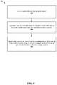
- FIG. 4is a flowchart illustrating a method 400 of operating the cooking instrument (e.g., the cooking instrument 100 , the cooking instrument 200 , and/or the cooking instrument 300 ) to cook a food, in accordance with various embodiments.
- the method 400can be controlled by a computing device (e.g., the computing device 206 ).
- the computing devicecan select a cooking recipe (e.g., from a local cooking recipe library stored in the local memory (e.g., the operational memory 210 and/or the persistent memory 214 ) of the computing device and/or the cooking instrument, a heating library implemented by a cloud service accessible through a network interface (e.g., the network interface 226 ), or another external source connected to the computing device).
- a cooking recipee.g., from a local cooking recipe library stored in the local memory (e.g., the operational memory 210 and/or the persistent memory 214 ) of the computing device and/or the cooking instrument, a heating library implemented by a cloud service accessible through a network interface (e.g., the network interface 226 ), or another external source connected to the computing device).
- the computing devicecan identify a food profile of an food in or about to be in the cooking instrument.
- the computing devicecan utilize a camera to identify the food profile (e.g., performing image recognition of the food or scanning a digital label attached to an outer
- the computing devicecan instantiate and/or configure, based on the cooking recipe and/or the food profile, a heat adjustment algorithm to control a heating process of the food.
- the heat adjustment algorithmspecifies how to adjust the driving parameters of one or more heating elements in the cooking instrument based on input variables that may change over time.
- Input variablescan include time lapsed (e.g., from when the heating elements are first driven and/or when the heating process first begins), temperature (e.g., detected by a temperature sensor therein) within the cooking instrument, user input (e.g., via an external device connected to the computing device or a control panel of the cooking instrument), temperature within the food (e.g., as reported by a temperature probe inserted into the food and communicatively coupled to the computing device), real-time or asynchronous image analysis of the food, real-time or asynchronous audio signal analysis from a microphone inside or outside of the cooking instrument, real-time or asynchronous environment sensor output analysis, other data received over a network, other data generated by a component of the cooking instrument, or any combination thereof.
- the computing devicecan update, in real-time, the input variables and, at step 410 , re-adjust the driving parameters to the heating elements according to the heating adjustment algorithm.
- Part of the adjustment made by the heat adjustment algorithmcan include heat intensity, peak wavelength (e.g., for targeting different food or material within the cooking chamber), heat duration, topical heat location (e.g., zones), or any combination thereof.
- the computing devicecan configured the heating elements to apply different heating patterns to different zones on a tray in the cooking instrument.
- the different zonescan be portions of the tray or regions of food resting on the tray.
- the computing devicecan configure the heating elements to apply, simultaneously or sequentially, different heating patterns (e.g., heating levels) to different zones (e.g., areas above the tray) on the support tray by supplying different amount of power to different heating elements.
- the computing devicecan configure the heating elements to apply different heating patterns to different zones on the support tray by driving the heating elements of the heating system at varying peak wavelengths.
- the cooking instrumentcan include a perforated metallic sheet between the tray and at least one of the heating elements.
- the computing devicecan configure the heating elements to apply different heating patterns to different zones on the support tray by using the perforated metallic sheet to spatially block portions of waves emitted by the at least one of the heating elements.
- the computing devicecan compute, based on the heating adjustment algorithm, when to terminate the heating process (e.g., when the cooking instrument stops supplying power to the heating elements).
- the heating adjustment algorithmtakes into account whether the food is expected to be extracted out of the cooking instrument substantially immediately after the termination of the heating process (e.g., a high-speed mode). For example, the heating adjustment algorithm can shorten the expected termination time if the user indicates that the food will remain in the cooking instrument a preset duration after the termination of the heating process (e.g., a low stress mode).
- processes or methodsare presented in a given order, alternative embodiments may perform routines having steps, or employ systems having blocks, in a different order, and some processes or blocks may be deleted, moved, added, subdivided, combined, and/or modified to provide alternative or subcombinations. Each of these processes or blocks may be implemented in a variety of different ways. In addition, while processes or blocks are at times shown as being performed in series, these processes or blocks may instead be performed in parallel, or may be performed at different times. When a process or step is “based on” a value or a computation, the process or step should be interpreted as based at least on that value or that computation.
- FIG. 5 Ais a cross-sectional front view of a first example of a cooking instrument 500 (e.g., the cooking instrument 100 , the cooking instrument 200 , and/or the cooking instrument 300 ), in accordance with various embodiments.
- the cooking instrument 500includes a chamber 502 and one or more filament assemblies 506 (e.g., a filament assembly 506 A, a filament assembly 506 B, a filament assembly 506 C, a filament assembly 506 D, a filament assembly 506 E, a filament assembly 506 F, etc., collectively as the “filament assemblies 506 ”) at one or more locations in the chamber 502 .
- the filament assemblies 506can be part of the heating elements of the cooking instrument 500 .
- Each of the filament assemblies 506can include a containment vessel 508 surrounding a filament 510 .
- the containment vessel 508can be coated with reflective material to serve as a reflector 511 . This way, the reflector 511 is prevented from being fouled by debris.
- the containment vessel 508can be made of quartz.
- the reflective materialcan be gold or white ceramics, such as zirconium oxide, silicon oxide, etc.
- the filament assemblies 506can be tungsten halogen assemblies.
- the reflective materialcan be coated on a portion of an outer surface of each heating element that faces away from a tray 516 .
- the reflector 511is a separate component than each of the filament assemblies 506 and the containment vessel 508 .
- each of the reflector 511can be positioned adjacent to each of the filament assemblies 506 away from the center of the cooking chamber.
- the reflector 511is placed close enough to each of the filament assemblies 506 such that during normal operations (e.g., approximately 450 Fahrenheit or above), debris is burnt off between the reflector 511 and the filament assembly.
- at least one of the filament assemblies 506is between the reflector 511 and a glass covering.
- a glass coveringis between at least one of the filament assemblies 506 and the reflector 511 .
- a computing device(e.g., the computing device 206 ) can be configured to control the peak emission wavelengths of the filament assemblies 506 .
- the computing devicecan be configured to identify a food profile associated with food (e.g., in the chamber 502 ) based on sensor input (e.g., camera scanning a label) or the user input.
- the computing devicecan then determine one or more excitable wavelengths associated with the food profile.
- the computing devicecan drive the filament assemblies 506 to emit at a peak emission wavelength corresponding to at least one of the excitable wavelengths to heat the food.
- the chamber 502is entirely enclosed in metal. In some embodiments, the chamber 502 has the door. In some embodiments, the chamber 502 has one or more transparent windows (e.g., glass windows). In some embodiments, one or more perforated metal sheets 512 (e.g., a perforated metal sheet 512 A and/or a perforated metal sheet 512 B, collectively as the “perforated metal sheets 512 ”) are disposed within the chamber 502 . In some embodiments, there is only a single perforated metal sheet in the chamber 502 (e.g., above the tray 516 or below the tray 516 ). In some embodiments, there are two perforated metal sheets (as shown).
- Each of the perforated metal sheets 512can be a removable or fixated panel.
- the perforated metal sheets 512can enable control of heating concentration along a horizontal plane parallel its surface.
- Perforated metal sheetssuch as a perforated aluminum foil, can be used to shield certain food items from the intense radiant heat generated by the heating elements. For example, when cooking a steak and vegetables side-by-side, the perforated metal sheets can shield the vegetables from being overcooked and enable the steak to receive the full power from the heating elements. Longer wavelength emission from the filament assemblies 506 can penetrate perforations more equally compared to shorter wavelength. Hence even if the perforations were designed to shield, for example, 90% of direct radiant heat, the cooking instrument can still independently tune the heating by varying the wavelength. This enables some control of side-by-side cooking in addition to direct radiant heating.
- the chamber 502includes the tray 516 (e.g., the cooking platform 110 ) in the chamber 502 .
- the tray 516includes or is part of at least one of the one or more perforated metal sheets 512 .
- the computing devicecan be configured to drive the heating elements to emit at a peak emission wavelength corresponding to excitable wavelength for the tray 516 . By tuning the peak emission wavelength to the excitable wavelength of the tray 516 , the computing device can heat up the tray 516 without directly heating the air or the food inside the chamber 502 .
- the tray 516can be made of glass.
- the tray 516can include an optically transparent region enabling visible light to substantially travel through two opposing surfaces of the tray 516 .
- a user of the cooking instrument 500can place an instruction sheet beneath the tray 516 while arranging food on the tray 516 to be cooked. The user can directly overlay specific food at the desired location according to the instruction sheet.
- the tray 516can include a reflective portion 518 to enable a top side camera 522 to capture a bottom view of food resting on the tray 516 .
- the cooking instrument 500can include an airflow-based cooling system 520 .
- the airflow-based cooling system 520can blow directly onto a reflector portion of the containment vessel 508 to cool (e.g., prevent vaporization of the reflective coating) and improve performance of the reflector 511 .
- the airflowcan be controlled to provide impingement convection heating.
- the airflow-based cooling system 520can have an air path that filters steam and thus prevents hot air from escaping when the door of the cooking instrument 500 is opened.
- the air pathcan also be configured to go over a camera (not shown) of the cooking instrument 500 to keep the lens of the camera condensation free.
- a fancan be installed away from the filament assemblies 506 .
- the fancan stir the air within the chamber 502 to ensure that heated air adjacent to the containment vessels 508 is moved to other parts of the chamber 502 to cook the food.
- the cooking instrument 500lacks a crumb tray.
- the cooking instrument 500can use quartz or other heat resistant sheet to cover the heating elements so that the bottom of the cooking instrument chamber has no heating elements to trip over.
- the heat resistant sheetcan be transparent at the operating wavelengths of the filament assemblies 506 to enable for the emission from the heating elements to penetrate through without much loss.
- the computing device within the cooking instrument 500can drive the filament assemblies 506 according to instructions in a cooking recipe.
- the computing devicecan drive at least one of the filament assemblies 506 at a specific peak wavelength.
- the specific peak wavelengthcan correspond to excitable wavelengths of the materials in the support tray, the containment vessel 508 (e.g., envelope of the filament assembly), a specific type of edible material, water molecules, or any combination thereof.
- the computing devicecan target specific material for heating.
- the computing devicecan drive at least one of the heating elements at a peak wavelength (e.g., 3 ⁇ m or above for glass trays) such that the support tray is substantially opaque to waves emitted from the at least one of the heating elements.
- the computing devicecan drive at least one of the heating elements at a peak wavelength (e.g., 3 ⁇ m or less for glass trays) such that the support tray is substantially transparent to waves emitted from the at least one of the heating elements.
- the computing devicecan drive at least one of the heating elements at a peak wavelength (e.g., between 3 ⁇ m and 4 ⁇ m for glass trays) such that the support tray is heated by waves emitted from the at least one of the heating elements without heating any organic food in the cooking chamber.
- FIG. 5 Bis a cross-sectional top view of the cooking instrument 500 of FIG. 5 A along lines A-A′, in accordance with various embodiments.
- FIG. 5 Bcan illustrate the perforated metal sheet 512 A and cavities within the perforated metal sheet 512 A that exposes the tray 516 .
- FIG. 5 Cis a cross-sectional top view of the cooking instrument 500 of FIG. 5 A along lines B-B′, in accordance with various embodiments.
- FIG. 5 Ccan illustrate the tray 516 .
- FIG. 5 Dis a cross-sectional top view of the cooking instrument 500 of FIG. 5 A along lines C-C′, in accordance with various embodiments.
- FIG. 5 Dcan illustrate the filament assemblies 506 .
- FIG. 6is a cross-sectional front view of a second example of a cooking instrument 600 , in accordance with various embodiments.
- This second examplecan illustrate various features in various embodiments of the disclosed cooking instrument.
- a particular feature, structure, or characteristic described in connection with the second examplecan be included in the first example. All of the described examples have features that are not mutually exclusive from other examples.
- the cooking instrument 600includes heating elements, and therefore filament assemblies (e.g., a filament assembly 606 A, a filament assembly 606 B, a filament assembly 606 C, and a filament assembly 606 D, collectively as the “filament assemblies 606 ”).
- the filament assemblies 606can differ from the filament assemblies 506 in that an upper set (e.g., the filament assemblies 606 A, 606 B, and 606 B) extends longitudinally at a substantially perpendicular angle from a lower set (e.g., the filament assembly 606 D and other filament assemblies not shown). Further unlike the filament assemblies 506 , the filament assemblies 606 are not uniformly spaced apart from each other.
- a reflector 611can be positioned to be spaced apart from each of the filament assemblies 606 .
- the reflector 611can be a standalone structure unlike the coating of the reflector 511 .
- the reflector 611can be spaced within a distance from a filament assembly (e.g., therefore a heating element) to have anti-fouling characteristics and to vaporize any food debris.
- the cooking instrument 600can include a fan 620 . Unlike the cooling system 520 , the fan 620 is not specifically directed to any of the filament assemblies 606 .
- a chamber 602is substantially similar to the chamber 502 .
- Perforated metal sheets 612 A and 612 Bare substantially similar to the perforated metal sheets 512 .
- a tray 616is substantially similar to the tray 516 , but does not include a reflective portion.
- the camera 622is substantially similar to the camera 522 .
- FIG. 7is a circuit diagram of a heating system 700 of a cooking instrument (e.g., the cooking instrument 100 , the cooking instrument 200 , and/or the cooking instrument 300 ), in accordance with various embodiments.
- the heating system 700can include a plurality of heating elements (e.g., a heating element 702 A, a heating element 702 B, etc., collectively the “heating elements 702 ”) configured to generate electromagnetic waves.
- Each heating elementis configurable to operate over a range of peak wavelengths.
- An alternating current (AC) power supply circuit 706is configured to provide, pipe, and/or convert AC power from an AC power line 710 to direct current (DC) power.
- the AC power line 710provides up to a maximum power threshold before triggering a circuit breaker.
- the AC power supply circuit 706can include a power factor correction (PFC) circuit.
- the AC power supply circuit 706can divide an AC power cycle from the AC power line into two half waves.
- a plurality of relay switchescan respectively correspond to the plurality of heating elements 702 .
- the relay switches 714can be TRIAC switches.
- the DC power from the AC power supply circuit 706is routed to a heating element when a corresponding relay switch is switched on.
- a control circuit 718is configured to switch on a subset of the plurality of relay switches 714 such that a total power drawn through the relay switches is equal to or below the maximum power threshold.
- the control circuit 718can be configured to switch on a single relay switch at a time to concentrate the DC power provided via the AC power supply at the maximum power threshold to a single heating element.
- the control circuit 718can include a processor (e.g., the computing device 206 ).
- the relay switches 714can be configured by the control circuit 718 to provide one half wave to a first heating element and another half wave to a second heating element.
- FIG. 8is a flow chart illustrating a method 800 of operating a cooking instrument (e.g., the cooking instrument 100 ), in accordance with various embodiments.
- the cooking instrumentcan draw alternating current (AC) power from an external power source (e.g., the AC power line 710 , such as an AC utility grid) substantially at an expected maximum power draw limit (e.g., circuit breaker limit) of the external power source.
- ACalternating current
- the expected maximum power drawcan be embodied in the implementation or configuration of a power component (e.g., the power source 202 ).
- the cooking instrumentcan include an electronic component (e.g., a power relay, triac circuit, thyristor circuit, etc.), specifically selected, configured, or adapted to gate the incoming current from the external power source substantially at the expected maximum power draw limit.
- an electronic componente.g., a power relay, triac circuit, thyristor circuit, etc.
- the cooking instrumentcan generate a maximum available power for a heating system (e.g., the heating elements 114 ) of the cooking instrument via the power component (e.g., the power source 202 ) that provides the drawn AC power.
- the maximum available power for the heating systemis less than or equal to the expected maximum power draw limit from the external power source.
- the maximum available power for the heating systemis approximately the total power drawn (e.g., set at the expected maximum power draw limit) by the power component minus both power dissipation in the power component and power distributed to one or more other loads (e.g., a computing system, a camera, etc.) in the cooking instrument.
- the cooking instrumentcan directionally heat each of different zones in a cooking chamber (e.g., the chamber 102 ) of the cooking instrument in sequence using one or more heating elements (e.g., the heating elements 114 ) of the heating system from at least one side of the cooking chamber such that each step in the sequence utilizes the maximum available power for the heating system.
- each step of the sequenceincludes heating directionally to a first zone for the same duration and/or same intensity as heating directionally to a second zone in another step in the sequence.
- consecutive stepsdo not necessarily have the same duration or intensity.
- a cooking platform holding food in the cooking chamberremains stationary. This advantageously ensures that each zone corresponds to an area of the target food.
- Directionally heatingcan be achieved by emitting electromagnetic waves with a planar intensity distribution that is substantially uneven at a cooking platform surface and that is substantially parallel to the at least one side.
- the different zonescan be respectively targeted by different heating elements/filament assemblies (e.g., the heating elements 114 or the heating elements 218 ). These heating elements can be directional heating elements facing toward the different zones (e.g., areas above a support tray, such as the cooking platform 110 or the tray 516 ).
- the different zonescan be respectively targeted by a single directional heating element (e.g., by redirecting the emitted wireless power or by turning the single directional heating element mechanically).
- the heating systemcan heat food using at least one of the heating elements.
- a heating elementcan emit wireless waves (e.g., electromagnetic energy).
- the cooking instrumentcan heat by alternatingly activating or rotating through different subsets of the heating elements on the at least one side of the cooking instrument. Each different subset can include at least a single heating element.
- the cooking instrumentcan activate each different subset by at least configuring each different subset with the same spectral emission configuration.
- the alternation of the subsetsis cyclical (e.g., by repeating the sequence of the subsets).
- the cooking instrumentcan control the spectral emission configuration of a heating element by specifying the spectral distribution of the emitted waves.
- the cooking instrumenttargets the different zones using different spectral emission configurations.
- the cooking instrumentheats food by emitting electromagnetic waves with an emission spectrum configured to directly transfer heat to food in the cooking chamber. “Direct transfer” of heat can be accomplished by ensuring that a substantial peak emission wavelength of the emission spectrum corresponds to a resonant frequency of the food.
- Other types of heatingincludes heating a tray holding the food or heating the air and thus indirectly heating the food.
- the heating elementsinclude at least three heating elements spaced equally apart.
- each step of the sequencelasts at least a second in time. That is, the cooking instrument (e.g., via the computing device 206 ) is configured to drive each of the subsets at the same power level for a duration at 1 second or longer to transfer sufficient heat to cook food in the respective target zone of each subset.
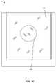
- FIG. 9is a flowchart illustrating a method 900 of operating a cooking appliance to cook an edible substance in different modes, in accordance with various embodiments.
- a computing device of the cooking appliancecan be configured to execute a heat adjustment algorithm/process based on a cooking recipe that specifies driving logic for operating one or more heating elements of the cooking appliance.
- the cooking recipecan specify which of the heating elements to turn on (e.g., controlling the directionality of heating).
- the cooking recipecan dictate that heating elements from below a tray are turned on and heating elements from above the tray are turned off.
- the cooking appliancecan be simulating a range top.
- the cooking appliancecan heat up the edible substance in a number of ways.
- the cooking appliancecan be configured to heat the edible substance directly.
- the cooking appliancecan be configured to directly heat its internal chamber (e.g., its chamber walls and its tray) and let the blackbody-like emission from the walls of its internal chamber heat the edible substance.
- the blackbody-like emissionis not the reflection of the wireless waves emitted from the heating elements, rather it is the emission/radiation released from the walls being heated.
- the spectral distribution of the blackbody-like emissionwould be different from the spectral distribution of the reflected waves from the heating elements.
- the cooking appliancecan be configured to heat the internal chamber and the edible substance simultaneously. The heated air in the internal chamber can also heat up the edible substance.
- the cooking appliancecan further be configured to provide airflow of heated air to cook the food as an impingement convection oven. At a lower airflow speed, the cooking appliance can be configured as a regular convection oven.
- the computing devicecan specifically target different items to heat up. Because an item can have multiple excitable wavelengths, the computing device can select different peak emission wavelengths to control the cooking speed/efficiency provided by the heating elements.
- the disclosed cooking appliancecan include a choke circuit that caps the power drawn to be within the limit of typical circuit breakers.
- typical circuit breakerscan tolerate sudden large surges, but not a relatively consistent draw above 1800 Watt).
- the choke circuitcan cause the cooking appliance to warm up slower initially to prevent blowing a fuse in a circuit breaker.
- the computing devicecan configure the heat adjustment algorithm to operate according to either a low-stress mode or a high speed mode.
- the computing devicecan monitor one or more feedback control signals from one or more sensors of the cooking appliance.
- the feedback control signalscan include a temperature reading signal from a temperature probe, an optical feedback signal from an optical sensor (e.g., a camera), or a combination thereof.
- the computing devicecan drive the one or more heating elements to cook the edible substance based on the cooking recipe and whether the cooking recipe is configured to operate in the low-stress mode or the high speed mode.
- the computing devicecan drive the one or more heating elements further based on the feedback control signals.
- the computing devicecan calculate a projection (e.g., heating trajectory) of when to complete cooking and turn off the heating elements.
- the control of the heating elementsis dynamic (e.g., based on feedback control signals from the temperature probe or from the camera), and hence completion time is not yet known.
- the computing devicecan turn off power to the heating elements.
- the computing devicecan determine when to present a completion indicator of the heat adjustment algorithm according to whether the cooking recipe is configured to be in the low-stress mode or the high speed mode. In some embodiments, the computing device can determine when to present the completion indicator based on the feedback control signals (e.g., when the searing is “visually” done according to an optical sensor or when the edible substance has reached a certain temperature for a certain period of time).
- the high speed moderequires extraction of the edible substance from the cooking appliance when the completion indicator is presented (e.g., otherwise the edible substance will overcook).
- the low-stress modeallows for the extraction to occur within a preset time range (e.g., from immediately to within 30 minutes or from immediately to within two to three hours).
- the cooking appliancecan present the completion indicator when the computing device turns off the power to the heating elements.
- the computing devicecan present the completion indicator a certain amount of time after the computing device turns off the power to the heating elements. For example, after the power to the heating elements is turned off, the tray and/or the chamber walls of the cooking appliance remain as blackbody-like emission sources. The internal air is also still at a high temperature.
- the computing devicecan simulate a blackbody emitter and the hot air using a computerized model to compute/predict the heating trajectory of the edible substance.
- the computing devicecan present the completion indicator once the heating trajectory has reached a point where the blackbody emission has died down sufficiently and the hot air has cooled such that they do not cause the edible substance to be overcooked or go stale even if the edible substance remains in the chamber for a preset range of time.
- processes or methodsare presented in a given order, alternative embodiments may perform routines having steps, or employ systems having blocks, in a different order, and some processes or blocks may be deleted, moved, added, subdivided, combined, and/or modified to provide alternative or subcombinations. Each of these processes or blocks may be implemented in a variety of different ways. In addition, while processes or blocks are at times shown as being performed in series, these processes or blocks may instead be performed in parallel, or may be performed at different times. When a process or step is “based on” a value or a computation, the process or step should be interpreted as based at least on that value or that computation.
Landscapes
- Engineering & Computer Science (AREA)
- Chemical & Material Sciences (AREA)
- Combustion & Propulsion (AREA)
- Mechanical Engineering (AREA)
- General Engineering & Computer Science (AREA)
- Food Science & Technology (AREA)
- Physics & Mathematics (AREA)
- Electromagnetism (AREA)
- Electric Stoves And Ranges (AREA)
Abstract
Description
Claims (22)
Priority Applications (1)
| Application Number | Priority Date | Filing Date | Title |
|---|---|---|---|
| US16/120,100US11523707B2 (en) | 2015-09-10 | 2018-08-31 | Sequential broiling |
Applications Claiming Priority (9)
| Application Number | Priority Date | Filing Date | Title |
|---|---|---|---|
| US201562216859P | 2015-09-10 | 2015-09-10 | |
| US201562218942P | 2015-09-15 | 2015-09-15 | |
| US201562240794P | 2015-10-13 | 2015-10-13 | |
| US201562249456P | 2015-11-02 | 2015-11-02 | |
| US201562256626P | 2015-11-17 | 2015-11-17 | |
| US201662370076P | 2016-08-02 | 2016-08-02 | |
| US15/261,784US10760794B2 (en) | 2015-09-10 | 2016-09-09 | In-oven camera |
| US15/659,543US10085592B1 (en) | 2015-09-10 | 2017-07-25 | Sequential broiling |
| US16/120,100US11523707B2 (en) | 2015-09-10 | 2018-08-31 | Sequential broiling |
Related Parent Applications (1)
| Application Number | Title | Priority Date | Filing Date |
|---|---|---|---|
| US15/659,543ContinuationUS10085592B1 (en) | 2015-09-10 | 2017-07-25 | Sequential broiling |
Publications (2)
| Publication Number | Publication Date |
|---|---|
| US20190008320A1 US20190008320A1 (en) | 2019-01-10 |
| US11523707B2true US11523707B2 (en) | 2022-12-13 |
Family
ID=63639351
Family Applications (2)
| Application Number | Title | Priority Date | Filing Date |
|---|---|---|---|
| US15/659,543Active2036-09-10US10085592B1 (en) | 2015-09-10 | 2017-07-25 | Sequential broiling |
| US16/120,100Active2037-01-29US11523707B2 (en) | 2015-09-10 | 2018-08-31 | Sequential broiling |
Family Applications Before (1)
| Application Number | Title | Priority Date | Filing Date |
|---|---|---|---|
| US15/659,543Active2036-09-10US10085592B1 (en) | 2015-09-10 | 2017-07-25 | Sequential broiling |
Country Status (1)
| Country | Link |
|---|---|
| US (2) | US10085592B1 (en) |
Families Citing this family (12)
| Publication number | Priority date | Publication date | Assignee | Title |
|---|---|---|---|---|
| US11388788B2 (en)* | 2015-09-10 | 2022-07-12 | Brava Home, Inc. | In-oven camera and computer vision systems and methods |
| KR20170053947A (en)* | 2015-11-09 | 2017-05-17 | 삼성전자주식회사 | Cooking apparatus, and control method for the same |
| DE102015225928A1 (en)* | 2015-12-18 | 2017-06-22 | BSH Hausgeräte GmbH | Radiator arrangement for a cooking appliance and cooking appliance with a corresponding radiator arrangement |
| KR101968553B1 (en) | 2017-01-04 | 2019-04-12 | 엘지전자 주식회사 | Induction heat cooking apparatus to implement wpt and pfc power converter |
| WO2019090260A1 (en)* | 2017-11-06 | 2019-05-09 | Brava Home, Inc. | Spectral power density configuration in a cooking instrument |
| US12402982B2 (en) | 2017-12-28 | 2025-09-02 | Iveneer Ltd | Matrices including crowns for dental restoration |
| US10952815B2 (en) | 2017-12-28 | 2021-03-23 | Itay MISHAELOFF | Matrices for dental restoration |
| US11422037B2 (en)* | 2018-03-15 | 2022-08-23 | Brava Home, Inc. | Temperature probe systems and methods |
| US11047578B2 (en) | 2019-01-04 | 2021-06-29 | Whirlpool Corporation | Automatic oven |
| CN110613363B (en)* | 2019-04-17 | 2021-02-19 | 广东格兰仕集团有限公司 | Camera module mounting structure of steaming and baking oven and steaming and baking oven |
| EP4269875A3 (en)* | 2019-11-20 | 2023-11-08 | Guangdong Midea Kitchen Appliances Manufacturing Co., Ltd. | Cooking apparatus, control method thereof, heating control method, and server |
| CN111035276B (en)* | 2019-12-31 | 2021-12-10 | 广东美的厨房电器制造有限公司 | A embedded oven that is used for oven door subassembly of embedded oven and has it |
Citations (105)
| Publication number | Priority date | Publication date | Assignee | Title |
|---|---|---|---|---|
| US3407285A (en) | 1965-10-23 | 1968-10-22 | Gen Motors Corp | Domestic range with variable area cooking regions |
| FR2284243A1 (en) | 1974-09-05 | 1976-04-02 | Dietrich & Cie De | Power switching between oven heating elements - by bimetal strips controlling members alternately powering elements |
| US4117294A (en) | 1975-06-12 | 1978-09-26 | U.S. Philips Corporation | Safety arrangement for microwave ovens |
| US4335293A (en) | 1976-02-17 | 1982-06-15 | Matsushita Electric Industrial Co., Ltd. | Heating control apparatus by humidity detection |
| US4441015A (en) | 1982-01-04 | 1984-04-03 | General Electric Company | Cooking apparatus employing a rotisserie mode with stationary food |
| US4473732A (en) | 1981-01-07 | 1984-09-25 | General Electric Company | Power circuit for induction cooking |
| US4475024A (en) | 1978-04-10 | 1984-10-02 | Sharp Kabushiki Kaisha | Wireless food temperature-sensing assembly |
| US4771154A (en) | 1985-12-11 | 1988-09-13 | Thorn Emi Appliances Limited | Oven with fluid heat transfer for browning food including a microwave energy source |
| US4800090A (en) | 1987-03-11 | 1989-01-24 | Musser's Potato Chips, Inc. | Infrared and microwave energy treatment of food |
| JPH03136619A (en) | 1989-07-18 | 1991-06-11 | Tsuguto Yamazaki | Far infrared radiation heat cooking method and device therefor |
| JPH03504891A (en) | 1988-05-19 | 1991-10-24 | カドラックス・インク | Oven and cooking method using this oven |
| WO1993003310A1 (en) | 1991-07-30 | 1993-02-18 | Quadlux, Inc. | Cooking apparatus using electron and molecular excitation mode |
| JPH05303629A (en) | 1991-11-29 | 1993-11-16 | Nec Corp | Shape synthesis method |
| JPH0624147A (en) | 1993-06-15 | 1994-02-01 | Mitsubishi Rayon Co Ltd | Optical information recording medium |
| JPH06201137A (en) | 1992-12-28 | 1994-07-19 | Matsushita Electric Ind Co Ltd | Cooker |
| US5349163A (en) | 1990-08-17 | 1994-09-20 | Samsung Electronics Co., Ltd. | Method of automatically cooking food by detecting the amount of gas or smoke being exhausted from a cooking device during cooking |
| US5517005A (en) | 1988-05-19 | 1996-05-14 | Quadlux, Inc. | Visible light and infra-red cooking apparatus |
| WO1997009865A1 (en) | 1995-09-08 | 1997-03-13 | Boddy Victor R | Oven with selectively energized heating elements |
| US5665259A (en) | 1988-05-19 | 1997-09-09 | Quadlux, Inc. | Method of cooking food in a lightwave oven using visible light without vaporizing all surface water on the food |
| WO1998030941A1 (en) | 1997-01-13 | 1998-07-16 | Merloni Elettrodomestici S.P.A. | Control system for a household appliance |
| US5877477A (en) | 1996-12-18 | 1999-03-02 | Amana Company, L.P. | Oven with high power radiant cooking elements and methods of developing, optimizing, storing, and retrieving recipes for the operation of the oven |
| US5990454A (en) | 1997-09-23 | 1999-11-23 | Quadlux, Inc. | Lightwave oven and method of cooking therewith having multiple cook modes and sequential lamp operation |
| US6011242A (en) | 1993-11-01 | 2000-01-04 | Quadlux, Inc. | Method and apparatus of cooking food in a lightwave oven |
| US6013900A (en) | 1997-09-23 | 2000-01-11 | Quadlux, Inc. | High efficiency lightwave oven |
| US6069345A (en) | 1997-12-11 | 2000-05-30 | Quadlux, Inc. | Apparatus and method for cooking food with a controlled spectrum |
| JP2001506360A (en) | 1997-09-05 | 2001-05-15 | カドラックス・インク | Lightwave oven and method of cooking with lightwave oven having multiple cooking modes and continuous lamp operation |
| JP2001263679A (en) | 2000-03-23 | 2001-09-26 | Lg Electronics Inc | Device and method for controlling halogen heater of microwave oven |
| US6302095B1 (en) | 2000-03-29 | 2001-10-16 | Tibs, Inc. | Burn prevention screen for use with an outdoor cooking grill |
| JP2002107317A (en) | 2000-10-02 | 2002-04-10 | Sanyo Seiko Kk | Device for observing high-temperature |
| JP2002156117A (en) | 2000-11-17 | 2002-05-31 | Matsushita Electric Ind Co Ltd | Method for providing a heating pattern of lunch-like food by information processing device, and information processing device |
| JP2002165550A (en) | 2000-11-29 | 2002-06-11 | Matsushita Electric Ind Co Ltd | Heating equipment |
| US6417494B1 (en) | 1999-01-08 | 2002-07-09 | Quadlux, Inc. | Scanning lightwave oven and method of operating the same |
| JP2002206753A (en) | 2001-01-09 | 2002-07-26 | Matsushita Electric Ind Co Ltd | Cooking utensils |
| US6448540B1 (en) | 1998-10-15 | 2002-09-10 | Whirlpool Corporation | Microwave oven with browning device |
| US20020171674A1 (en) | 2001-05-15 | 2002-11-21 | Paris Harry G. | Kitchen internet appliance |
| JP2003142247A (en) | 2001-10-31 | 2003-05-16 | Hitachi Hometec Ltd | Combined cooking device |
| JP2003215470A (en) | 2002-12-10 | 2003-07-30 | Asahi Glass Co Ltd | In-furnace observation device |
| US6843207B2 (en) | 2002-09-03 | 2005-01-18 | Matsushita Electric Industrial Co., Ltd. | Water supply tank unit |
| US20050173400A1 (en) | 2004-02-10 | 2005-08-11 | Hp Intellectual Corporation | Multi-purpose oven using infrared heating for reduced cooking time |
| US7075442B2 (en) | 2003-07-07 | 2006-07-11 | Mastrad Sa | Food temperature monitoring device |
| JP2006275489A (en) | 2005-03-30 | 2006-10-12 | Toshiba Corp | Cooking system |
| US20060289436A1 (en) | 2005-05-06 | 2006-12-28 | Viking Range Corporation | Multi-mode convection oven with flow control baffles |
| EP1740018A1 (en) | 2005-06-27 | 2007-01-03 | Samsung Electronics Co., Ltd. | Microwave oven using bar code and method for controlling the same |
| USD541578S1 (en) | 2006-09-15 | 2007-05-01 | Samsung Electronics Co., Ltd. | Oven |
| EP1793171A1 (en) | 2004-08-31 | 2007-06-06 | Sharp Kabushiki Kaisha | Heating cooking apparatus |
| RU2006102663A (en) | 2006-01-31 | 2007-08-20 | Григорий Григорьевич Губриенко (RU) | MICROWAVE WITH A BUILT-IN TV |
| US20080259995A1 (en) | 2007-04-23 | 2008-10-23 | Miele & Cie. Kg | Temperature measuring probe, in particular for a household appliance |
| US20090034944A1 (en) | 2007-07-30 | 2009-02-05 | Burtea Sanda | Conveyor oven with multiple heating zones |
| USD586180S1 (en) | 2008-08-05 | 2009-02-10 | Sunbeam Products, Inc. | Toaster oven |
| CN101371756A (en) | 2007-08-24 | 2009-02-25 | Lg电子株式会社 | Electric oven with multiple baking heaters and method for preheating the same |
| JP2009052817A (en) | 2007-08-28 | 2009-03-12 | Panasonic Corp | Cooking equipment |
| CN101398197A (en) | 2008-10-20 | 2009-04-01 | 郭恒勋 | Micro-wave oven without microwave radiation |
| JP2009068734A (en) | 2007-09-11 | 2009-04-02 | Panasonic Corp | Heating device with steam generating function |
| US20090102083A1 (en) | 2007-06-08 | 2009-04-23 | Cochran Don W | Method and System for Wavelength Specific Thermal Irradiation and Treatment |
| WO2009091145A2 (en) | 2008-01-03 | 2009-07-23 | Lg Electronics Inc. | Cooker and controlling method for the same |
| RU2008111110A (en) | 2008-03-25 | 2009-09-27 | Закрытое акционерное общество "Тулаторгтехника" (RU) | KITCHEN ELECTRIC PLATE BOILER AND KITCHEN ELECTRIC PLATE |
| USD602306S1 (en) | 2008-09-25 | 2009-10-20 | Danny Lavy | Toaster oven |
| US20090272814A1 (en) | 2008-05-05 | 2009-11-05 | Recco Systems Ab | Passive Transponder and an Item with a Passive Transponder |
| US7619186B2 (en) | 2004-02-10 | 2009-11-17 | Applica Consumer Products, Inc. | Intelligent user interface for multi-purpose oven using infrared heating for reduced cooking time |
| US20100186600A1 (en) | 2009-01-29 | 2010-07-29 | Bradly Joel Lewis | Multi device programmable cooking timer and method of use |
| US20100199857A1 (en) | 2007-07-10 | 2010-08-12 | Paul Storiz | Multi-zone composite cooking griddle with unitary thermally conductive plate |
| WO2010102261A1 (en) | 2009-03-05 | 2010-09-10 | Pressco Technology, Inc. | A method and system for digital narrowband, wavelength specific cooking, curing, food preparation, and processing |
| EP2243407A1 (en) | 2008-02-04 | 2010-10-27 | Crambo, S.a. | Device and method for controlling toasting and baking |
| USD629639S1 (en) | 2009-12-14 | 2010-12-28 | Juan Fernandez | Electric oven with adjustable heating element |
| US20110002677A1 (en) | 2004-12-03 | 2011-01-06 | Cochran Don W | Method and system for digital narrowband, wavelength specific cooking, curing, food preparation, and processing |
| US20110002675A1 (en) | 2009-03-05 | 2011-01-06 | Cochran Don W | Digital heat injection by way of surface emitting semi-conductor devices |
| US20110114633A1 (en) | 2009-11-18 | 2011-05-19 | Whirlpool Corporation | Microwave oven and related method |
| US20110114627A1 (en) | 2008-09-15 | 2011-05-19 | General Electric Company | System and method for minimizing consumer impact during demand responses |
| RU110892U1 (en) | 2011-06-20 | 2011-11-27 | Евгений Александрович Патыков | HOUSEHOLD MICROWAVE FURNACE EQUIPPED WITH A CCTV DEVICE |
| US20120063753A1 (en) | 2010-06-11 | 2012-03-15 | Cochran Don W | Cookware and cook-packs for narrowband irradiation cooking and systems and methods thereof |
| US8200548B2 (en) | 2009-08-31 | 2012-06-12 | Peter Wiedl | Recipe engine system and method |
| US20120180775A1 (en) | 2011-01-17 | 2012-07-19 | Cleveland Range LLC. | Impingement oven with a plurality of variable airflow cooking zones |
| EP2515044A1 (en) | 2011-04-20 | 2012-10-24 | Miele & Cie. KG | Cooking system |
| JP2013081773A (en) | 2011-09-30 | 2013-05-09 | Gac Corp | Showcase apparatus |
| US20130202754A1 (en) | 2010-06-11 | 2013-08-08 | Pressco Ip Llc | Cookware and cook-packs for narrowband irradiation cooking and systems and methods thereof |
| DE102012204229A1 (en) | 2012-03-16 | 2013-09-19 | BSH Bosch und Siemens Hausgeräte GmbH | Cooking appliance device e.g. baking oven, for cooking food, has recognition unit recognizing food in cooking chamber, and selection unit selecting determined cooking programs from predetermined cooking programs in dependence of image |
| EP2662628A1 (en) | 2012-05-08 | 2013-11-13 | Electrolux Home Products Corporation N.V. | Appliance for processing food and method of operating the same |
| WO2014086487A1 (en) | 2012-12-04 | 2014-06-12 | Ingo Stork Genannt Wersborg | Heat treatment device with monitoring system |
| CN103860037A (en) | 2012-12-11 | 2014-06-18 | 加兰工商业有限责任公司 | Cooking grill with multiple gas heating zones front to back for improved grill plate temperature management |
| US8791398B2 (en) | 2010-03-03 | 2014-07-29 | Bsh Bosch Und Siemens Hausgeraete Gmbh | Hob having at least one cooking zone and method for operating a hob |
| US8929724B1 (en)* | 2011-02-07 | 2015-01-06 | J.C. Penney Purchasing Corporation, Inc. | High efficiency oven and method of use |
| KR101520232B1 (en) | 2014-10-15 | 2015-05-13 | 성진하이쿨(주) | Fried apparatus |
| JP2015226662A (en) | 2014-06-02 | 2015-12-17 | 富士電機株式会社 | Showcase |
| JP2016011763A (en) | 2014-06-27 | 2016-01-21 | 東芝ホームテクノ株式会社 | Electric heater |
| US20160033140A1 (en) | 2014-07-30 | 2016-02-04 | General Electric Company | Oven appliance with interior cleanliness sensor |
| US9414444B2 (en) | 2011-02-11 | 2016-08-09 | Goji Ltd. | Interface for controlling energy application apparatus |
| US9460633B2 (en) | 2012-04-16 | 2016-10-04 | Eugenio Minvielle | Conditioner with sensors for nutritional substances |
| US20160327279A1 (en) | 2015-05-05 | 2016-11-10 | June Life, Inc. | Connected food preparation system and method of use |
| USD771996S1 (en) | 2015-06-08 | 2016-11-22 | June Life, Inc. | Countertop oven with cooling features |
| USD771995S1 (en) | 2015-06-08 | 2016-11-22 | June Life, Inc. | Countertop oven |
| US20160348918A1 (en) | 2015-06-01 | 2016-12-01 | June Life, Inc. | Thermal management system and method for a connected oven |
| US9528972B2 (en) | 2012-04-16 | 2016-12-27 | Eugenio Minvielle | Dynamic recipe control |
| USD777504S1 (en) | 2015-06-08 | 2017-01-31 | June Life, Inc. | Countertop oven with bumper |
| WO2017044876A1 (en) | 2015-09-10 | 2017-03-16 | Brava Home, Inc. | In-oven camera |
| USD782864S1 (en) | 2015-06-08 | 2017-04-04 | June Life, Inc. | Countertop oven |
| USD783336S1 (en) | 2015-07-09 | 2017-04-11 | Samsung Electronics Co., Ltd. | Microwave oven |
| US20170099988A1 (en) | 2015-10-09 | 2017-04-13 | Geniuss Inc. | INTEGRATED OVEN with a TABLET COMPUTER/FLAT PANEL DISPLAY |
| US20170215233A1 (en) | 2016-01-22 | 2017-07-27 | Pressco Ip Llc | System and method for producing an engineered irradiation pattern in a narrowband system |
| US20170211819A1 (en) | 2015-06-08 | 2017-07-27 | Alto-Shaam, Inc. | Low-Profile Multi-Zone Oven |
| US20170223774A1 (en) | 2015-09-10 | 2017-08-03 | Brava Home, Inc. | Variable peak wavelength cooking instrument with support tray |
| USD802996S1 (en) | 2015-06-08 | 2017-11-21 | June Life, Inc. | Door for a countertop oven |
| WO2018026846A1 (en) | 2016-08-02 | 2018-02-08 | Brava Home, Inc. | Variable peak wavelength cooking instrument with support tray |
| US20180128493A1 (en) | 2016-06-09 | 2018-05-10 | Electrolux Home Products, Inc. | Appliance with intuitive cooking temperature feedback interface |
| US20180172510A1 (en) | 2016-12-08 | 2018-06-21 | Verifood, Ltd. | Spectrometry system applications |
| US20180184668A1 (en) | 2014-06-05 | 2018-07-05 | Ingo Stork Genannt Wersborg | Heat treatment monitoring system |
- 2017
- 2017-07-25USUS15/659,543patent/US10085592B1/enactiveActive
- 2018
- 2018-08-31USUS16/120,100patent/US11523707B2/enactiveActive
Patent Citations (114)
| Publication number | Priority date | Publication date | Assignee | Title |
|---|---|---|---|---|
| US3407285A (en) | 1965-10-23 | 1968-10-22 | Gen Motors Corp | Domestic range with variable area cooking regions |
| FR2284243A1 (en) | 1974-09-05 | 1976-04-02 | Dietrich & Cie De | Power switching between oven heating elements - by bimetal strips controlling members alternately powering elements |
| US4117294A (en) | 1975-06-12 | 1978-09-26 | U.S. Philips Corporation | Safety arrangement for microwave ovens |
| US4335293A (en) | 1976-02-17 | 1982-06-15 | Matsushita Electric Industrial Co., Ltd. | Heating control apparatus by humidity detection |
| US4475024A (en) | 1978-04-10 | 1984-10-02 | Sharp Kabushiki Kaisha | Wireless food temperature-sensing assembly |
| US4473732A (en) | 1981-01-07 | 1984-09-25 | General Electric Company | Power circuit for induction cooking |
| US4441015A (en) | 1982-01-04 | 1984-04-03 | General Electric Company | Cooking apparatus employing a rotisserie mode with stationary food |
| US4771154A (en) | 1985-12-11 | 1988-09-13 | Thorn Emi Appliances Limited | Oven with fluid heat transfer for browning food including a microwave energy source |
| US4800090A (en) | 1987-03-11 | 1989-01-24 | Musser's Potato Chips, Inc. | Infrared and microwave energy treatment of food |
| JPH03504891A (en) | 1988-05-19 | 1991-10-24 | カドラックス・インク | Oven and cooking method using this oven |
| US5517005A (en) | 1988-05-19 | 1996-05-14 | Quadlux, Inc. | Visible light and infra-red cooking apparatus |
| US5665259A (en) | 1988-05-19 | 1997-09-09 | Quadlux, Inc. | Method of cooking food in a lightwave oven using visible light without vaporizing all surface water on the food |
| JPH03136619A (en) | 1989-07-18 | 1991-06-11 | Tsuguto Yamazaki | Far infrared radiation heat cooking method and device therefor |
| US5349163A (en) | 1990-08-17 | 1994-09-20 | Samsung Electronics Co., Ltd. | Method of automatically cooking food by detecting the amount of gas or smoke being exhausted from a cooking device during cooking |
| WO1993003310A1 (en) | 1991-07-30 | 1993-02-18 | Quadlux, Inc. | Cooking apparatus using electron and molecular excitation mode |
| JPH05303629A (en) | 1991-11-29 | 1993-11-16 | Nec Corp | Shape synthesis method |
| JPH06201137A (en) | 1992-12-28 | 1994-07-19 | Matsushita Electric Ind Co Ltd | Cooker |
| JPH0624147A (en) | 1993-06-15 | 1994-02-01 | Mitsubishi Rayon Co Ltd | Optical information recording medium |
| US6011242A (en) | 1993-11-01 | 2000-01-04 | Quadlux, Inc. | Method and apparatus of cooking food in a lightwave oven |
| WO1997009865A1 (en) | 1995-09-08 | 1997-03-13 | Boddy Victor R | Oven with selectively energized heating elements |
| US5877477A (en) | 1996-12-18 | 1999-03-02 | Amana Company, L.P. | Oven with high power radiant cooking elements and methods of developing, optimizing, storing, and retrieving recipes for the operation of the oven |
| WO1998030941A1 (en) | 1997-01-13 | 1998-07-16 | Merloni Elettrodomestici S.P.A. | Control system for a household appliance |
| JP2001506360A (en) | 1997-09-05 | 2001-05-15 | カドラックス・インク | Lightwave oven and method of cooking with lightwave oven having multiple cooking modes and continuous lamp operation |
| US6013900A (en) | 1997-09-23 | 2000-01-11 | Quadlux, Inc. | High efficiency lightwave oven |
| US5990454A (en) | 1997-09-23 | 1999-11-23 | Quadlux, Inc. | Lightwave oven and method of cooking therewith having multiple cook modes and sequential lamp operation |
| US6069345A (en) | 1997-12-11 | 2000-05-30 | Quadlux, Inc. | Apparatus and method for cooking food with a controlled spectrum |
| EP1121837B1 (en) | 1998-10-15 | 2004-01-21 | Whirlpool Corporation | Microwave oven with browning device |
| US6448540B1 (en) | 1998-10-15 | 2002-09-10 | Whirlpool Corporation | Microwave oven with browning device |
| US6417494B1 (en) | 1999-01-08 | 2002-07-09 | Quadlux, Inc. | Scanning lightwave oven and method of operating the same |
| JP2001263679A (en) | 2000-03-23 | 2001-09-26 | Lg Electronics Inc | Device and method for controlling halogen heater of microwave oven |
| US6302095B1 (en) | 2000-03-29 | 2001-10-16 | Tibs, Inc. | Burn prevention screen for use with an outdoor cooking grill |
| JP2002107317A (en) | 2000-10-02 | 2002-04-10 | Sanyo Seiko Kk | Device for observing high-temperature |
| JP2002156117A (en) | 2000-11-17 | 2002-05-31 | Matsushita Electric Ind Co Ltd | Method for providing a heating pattern of lunch-like food by information processing device, and information processing device |
| JP2002165550A (en) | 2000-11-29 | 2002-06-11 | Matsushita Electric Ind Co Ltd | Heating equipment |
| JP2002206753A (en) | 2001-01-09 | 2002-07-26 | Matsushita Electric Ind Co Ltd | Cooking utensils |
| US20020171674A1 (en) | 2001-05-15 | 2002-11-21 | Paris Harry G. | Kitchen internet appliance |
| JP2003142247A (en) | 2001-10-31 | 2003-05-16 | Hitachi Hometec Ltd | Combined cooking device |
| US6843207B2 (en) | 2002-09-03 | 2005-01-18 | Matsushita Electric Industrial Co., Ltd. | Water supply tank unit |
| JP2003215470A (en) | 2002-12-10 | 2003-07-30 | Asahi Glass Co Ltd | In-furnace observation device |
| US7075442B2 (en) | 2003-07-07 | 2006-07-11 | Mastrad Sa | Food temperature monitoring device |
| US20050173400A1 (en) | 2004-02-10 | 2005-08-11 | Hp Intellectual Corporation | Multi-purpose oven using infrared heating for reduced cooking time |
| US7683292B2 (en) | 2004-02-10 | 2010-03-23 | Applica Consumer Products, Inc. | Method for cooking a food with infrared radiant heat |
| US7619186B2 (en) | 2004-02-10 | 2009-11-17 | Applica Consumer Products, Inc. | Intelligent user interface for multi-purpose oven using infrared heating for reduced cooking time |
| US7323663B2 (en) | 2004-02-10 | 2008-01-29 | Applica Consumer Products, Inc. | Multi-purpose oven using infrared heating for reduced cooking time |
| RU2007111953A (en) | 2004-08-31 | 2008-10-10 | Шарп Кабусики Кайся (Jp) | OVEN |
| EP1793171A1 (en) | 2004-08-31 | 2007-06-06 | Sharp Kabushiki Kaisha | Heating cooking apparatus |
| US20110002677A1 (en) | 2004-12-03 | 2011-01-06 | Cochran Don W | Method and system for digital narrowband, wavelength specific cooking, curing, food preparation, and processing |
| JP2006275489A (en) | 2005-03-30 | 2006-10-12 | Toshiba Corp | Cooking system |
| US20060289436A1 (en) | 2005-05-06 | 2006-12-28 | Viking Range Corporation | Multi-mode convection oven with flow control baffles |
| CN1892673A (en) | 2005-06-27 | 2007-01-10 | 三星电子株式会社 | Microwave oven using bar code and method for controlling the same |
| EP1740018A1 (en) | 2005-06-27 | 2007-01-03 | Samsung Electronics Co., Ltd. | Microwave oven using bar code and method for controlling the same |
| RU2006102663A (en) | 2006-01-31 | 2007-08-20 | Григорий Григорьевич Губриенко (RU) | MICROWAVE WITH A BUILT-IN TV |
| USD541578S1 (en) | 2006-09-15 | 2007-05-01 | Samsung Electronics Co., Ltd. | Oven |
| US20080259995A1 (en) | 2007-04-23 | 2008-10-23 | Miele & Cie. Kg | Temperature measuring probe, in particular for a household appliance |
| US20090102083A1 (en) | 2007-06-08 | 2009-04-23 | Cochran Don W | Method and System for Wavelength Specific Thermal Irradiation and Treatment |
| US20100199857A1 (en) | 2007-07-10 | 2010-08-12 | Paul Storiz | Multi-zone composite cooking griddle with unitary thermally conductive plate |
| US20090034944A1 (en) | 2007-07-30 | 2009-02-05 | Burtea Sanda | Conveyor oven with multiple heating zones |
| CN101371756A (en) | 2007-08-24 | 2009-02-25 | Lg电子株式会社 | Electric oven with multiple baking heaters and method for preheating the same |
| JP2009052817A (en) | 2007-08-28 | 2009-03-12 | Panasonic Corp | Cooking equipment |
| JP2009068734A (en) | 2007-09-11 | 2009-04-02 | Panasonic Corp | Heating device with steam generating function |
| WO2009091145A2 (en) | 2008-01-03 | 2009-07-23 | Lg Electronics Inc. | Cooker and controlling method for the same |
| EP2243407A1 (en) | 2008-02-04 | 2010-10-27 | Crambo, S.a. | Device and method for controlling toasting and baking |
| RU2008111110A (en) | 2008-03-25 | 2009-09-27 | Закрытое акционерное общество "Тулаторгтехника" (RU) | KITCHEN ELECTRIC PLATE BOILER AND KITCHEN ELECTRIC PLATE |
| US20090272814A1 (en) | 2008-05-05 | 2009-11-05 | Recco Systems Ab | Passive Transponder and an Item with a Passive Transponder |
| USD586180S1 (en) | 2008-08-05 | 2009-02-10 | Sunbeam Products, Inc. | Toaster oven |
| US20110114627A1 (en) | 2008-09-15 | 2011-05-19 | General Electric Company | System and method for minimizing consumer impact during demand responses |
| USD602306S1 (en) | 2008-09-25 | 2009-10-20 | Danny Lavy | Toaster oven |
| CN101398197A (en) | 2008-10-20 | 2009-04-01 | 郭恒勋 | Micro-wave oven without microwave radiation |
| US20100186600A1 (en) | 2009-01-29 | 2010-07-29 | Bradly Joel Lewis | Multi device programmable cooking timer and method of use |
| US20110002675A1 (en) | 2009-03-05 | 2011-01-06 | Cochran Don W | Digital heat injection by way of surface emitting semi-conductor devices |
| WO2010102261A1 (en) | 2009-03-05 | 2010-09-10 | Pressco Technology, Inc. | A method and system for digital narrowband, wavelength specific cooking, curing, food preparation, and processing |
| CN102413712A (en) | 2009-03-05 | 2012-04-11 | 派拉斯科技术公司 | Methods and systems for digital narrowband wavelength specific cooking, ripening, food preparation and processing |
| US8200548B2 (en) | 2009-08-31 | 2012-06-12 | Peter Wiedl | Recipe engine system and method |
| US20110114633A1 (en) | 2009-11-18 | 2011-05-19 | Whirlpool Corporation | Microwave oven and related method |
| USD629639S1 (en) | 2009-12-14 | 2010-12-28 | Juan Fernandez | Electric oven with adjustable heating element |
| US8791398B2 (en) | 2010-03-03 | 2014-07-29 | Bsh Bosch Und Siemens Hausgeraete Gmbh | Hob having at least one cooking zone and method for operating a hob |
| US20130202754A1 (en) | 2010-06-11 | 2013-08-08 | Pressco Ip Llc | Cookware and cook-packs for narrowband irradiation cooking and systems and methods thereof |
| US20120063753A1 (en) | 2010-06-11 | 2012-03-15 | Cochran Don W | Cookware and cook-packs for narrowband irradiation cooking and systems and methods thereof |
| US20120180775A1 (en) | 2011-01-17 | 2012-07-19 | Cleveland Range LLC. | Impingement oven with a plurality of variable airflow cooking zones |
| US8929724B1 (en)* | 2011-02-07 | 2015-01-06 | J.C. Penney Purchasing Corporation, Inc. | High efficiency oven and method of use |
| US9414444B2 (en) | 2011-02-11 | 2016-08-09 | Goji Ltd. | Interface for controlling energy application apparatus |
| EP2515044A1 (en) | 2011-04-20 | 2012-10-24 | Miele & Cie. KG | Cooking system |
| RU110892U1 (en) | 2011-06-20 | 2011-11-27 | Евгений Александрович Патыков | HOUSEHOLD MICROWAVE FURNACE EQUIPPED WITH A CCTV DEVICE |
| JP2013081773A (en) | 2011-09-30 | 2013-05-09 | Gac Corp | Showcase apparatus |
| DE102012204229A1 (en) | 2012-03-16 | 2013-09-19 | BSH Bosch und Siemens Hausgeräte GmbH | Cooking appliance device e.g. baking oven, for cooking food, has recognition unit recognizing food in cooking chamber, and selection unit selecting determined cooking programs from predetermined cooking programs in dependence of image |
| US9528972B2 (en) | 2012-04-16 | 2016-12-27 | Eugenio Minvielle | Dynamic recipe control |
| US9460633B2 (en) | 2012-04-16 | 2016-10-04 | Eugenio Minvielle | Conditioner with sensors for nutritional substances |
| EP2662628A1 (en) | 2012-05-08 | 2013-11-13 | Electrolux Home Products Corporation N.V. | Appliance for processing food and method of operating the same |
| WO2014086486A2 (en) | 2012-12-04 | 2014-06-12 | Ingo Stork Genannt Wersborg | Heat treatment monitoring system |
| WO2014086487A1 (en) | 2012-12-04 | 2014-06-12 | Ingo Stork Genannt Wersborg | Heat treatment device with monitoring system |
| CN103860037A (en) | 2012-12-11 | 2014-06-18 | 加兰工商业有限责任公司 | Cooking grill with multiple gas heating zones front to back for improved grill plate temperature management |
| JP2015226662A (en) | 2014-06-02 | 2015-12-17 | 富士電機株式会社 | Showcase |
| US20180184668A1 (en) | 2014-06-05 | 2018-07-05 | Ingo Stork Genannt Wersborg | Heat treatment monitoring system |
| JP2016011763A (en) | 2014-06-27 | 2016-01-21 | 東芝ホームテクノ株式会社 | Electric heater |
| US20160033140A1 (en) | 2014-07-30 | 2016-02-04 | General Electric Company | Oven appliance with interior cleanliness sensor |
| KR101520232B1 (en) | 2014-10-15 | 2015-05-13 | 성진하이쿨(주) | Fried apparatus |
| US20160327279A1 (en) | 2015-05-05 | 2016-11-10 | June Life, Inc. | Connected food preparation system and method of use |
| US9927129B2 (en) | 2015-06-01 | 2018-03-27 | June Life, Inc. | Thermal management system and method for a connected oven |
| US20160348918A1 (en) | 2015-06-01 | 2016-12-01 | June Life, Inc. | Thermal management system and method for a connected oven |
| USD771995S1 (en) | 2015-06-08 | 2016-11-22 | June Life, Inc. | Countertop oven |
| US20170211819A1 (en) | 2015-06-08 | 2017-07-27 | Alto-Shaam, Inc. | Low-Profile Multi-Zone Oven |
| USD771996S1 (en) | 2015-06-08 | 2016-11-22 | June Life, Inc. | Countertop oven with cooling features |
| USD782864S1 (en) | 2015-06-08 | 2017-04-04 | June Life, Inc. | Countertop oven |
| USD777504S1 (en) | 2015-06-08 | 2017-01-31 | June Life, Inc. | Countertop oven with bumper |
| USD802996S1 (en) | 2015-06-08 | 2017-11-21 | June Life, Inc. | Door for a countertop oven |
| USD783336S1 (en) | 2015-07-09 | 2017-04-11 | Samsung Electronics Co., Ltd. | Microwave oven |
| US20170223774A1 (en) | 2015-09-10 | 2017-08-03 | Brava Home, Inc. | Variable peak wavelength cooking instrument with support tray |
| WO2017044876A1 (en) | 2015-09-10 | 2017-03-16 | Brava Home, Inc. | In-oven camera |
| US20170074522A1 (en) | 2015-09-10 | 2017-03-16 | Brava Home, Inc. | In-oven camera |
| US20170099988A1 (en) | 2015-10-09 | 2017-04-13 | Geniuss Inc. | INTEGRATED OVEN with a TABLET COMPUTER/FLAT PANEL DISPLAY |
| US20170215233A1 (en) | 2016-01-22 | 2017-07-27 | Pressco Ip Llc | System and method for producing an engineered irradiation pattern in a narrowband system |
| US20180128493A1 (en) | 2016-06-09 | 2018-05-10 | Electrolux Home Products, Inc. | Appliance with intuitive cooking temperature feedback interface |
| WO2018026846A1 (en) | 2016-08-02 | 2018-02-08 | Brava Home, Inc. | Variable peak wavelength cooking instrument with support tray |
| US20180172510A1 (en) | 2016-12-08 | 2018-06-21 | Verifood, Ltd. | Spectrometry system applications |
Also Published As
| Publication number | Publication date |
|---|---|
| US20190008320A1 (en) | 2019-01-10 |
| US10085592B1 (en) | 2018-10-02 |
Similar Documents
| Publication | Publication Date | Title |
|---|---|---|
| US12035428B2 (en) | Variable peak wavelength cooking instrument with support tray | |
| US11523707B2 (en) | Sequential broiling | |
| US11257394B2 (en) | Multizone cooking utilizing a spectral-configurable cooking instrument | |
| EP3494760B1 (en) | Cooking instrument with variable peak wavelength and support tray | |
| US12137510B2 (en) | Power density emission manipulation in a cooking instrument | |
| US20240255151A1 (en) | Spectral power density configuration in a cooking instrument | |
| CA3070682C (en) | Sequential broiling |
Legal Events
| Date | Code | Title | Description |
|---|---|---|---|
| FEPP | Fee payment procedure | Free format text:ENTITY STATUS SET TO UNDISCOUNTED (ORIGINAL EVENT CODE: BIG.); ENTITY STATUS OF PATENT OWNER: SMALL ENTITY | |
| FEPP | Fee payment procedure | Free format text:ENTITY STATUS SET TO SMALL (ORIGINAL EVENT CODE: SMAL); ENTITY STATUS OF PATENT OWNER: SMALL ENTITY | |
| STPP | Information on status: patent application and granting procedure in general | Free format text:DOCKETED NEW CASE - READY FOR EXAMINATION | |
| STPP | Information on status: patent application and granting procedure in general | Free format text:NON FINAL ACTION MAILED | |
| STPP | Information on status: patent application and granting procedure in general | Free format text:NON FINAL ACTION MAILED | |
| STPP | Information on status: patent application and granting procedure in general | Free format text:RESPONSE TO NON-FINAL OFFICE ACTION ENTERED AND FORWARDED TO EXAMINER | |
| STPP | Information on status: patent application and granting procedure in general | Free format text:NOTICE OF ALLOWANCE MAILED -- APPLICATION RECEIVED IN OFFICE OF PUBLICATIONS | |
| AS | Assignment | Owner name:BRAVA HOME, INC., CALIFORNIA Free format text:ASSIGNMENT OF ASSIGNORS INTEREST;ASSIGNOR:CHENG, SHIH-YU;REEL/FRAME:061734/0478 Effective date:20171201 | |
| STPP | Information on status: patent application and granting procedure in general | Free format text:PUBLICATIONS -- ISSUE FEE PAYMENT RECEIVED | |
| STPP | Information on status: patent application and granting procedure in general | Free format text:PUBLICATIONS -- ISSUE FEE PAYMENT VERIFIED | |
| STCF | Information on status: patent grant | Free format text:PATENTED CASE | |
| FEPP | Fee payment procedure | Free format text:ENTITY STATUS SET TO UNDISCOUNTED (ORIGINAL EVENT CODE: BIG.); ENTITY STATUS OF PATENT OWNER: LARGE ENTITY |