US11523556B2 - Particle delivery system of an agricultural row unit - Google Patents
Particle delivery system of an agricultural row unitDownload PDFInfo
- Publication number
- US11523556B2 US11523556B2US16/726,598US201916726598AUS11523556B2US 11523556 B2US11523556 B2US 11523556B2US 201916726598 AUS201916726598 AUS 201916726598AUS 11523556 B2US11523556 B2US 11523556B2
- Authority
- US
- United States
- Prior art keywords
- particle
- belt
- speed
- particles
- target
- Prior art date
- Legal status (The legal status is an assumption and is not a legal conclusion. Google has not performed a legal analysis and makes no representation as to the accuracy of the status listed.)
- Active, expires
Links
Images


Classifications
- A—HUMAN NECESSITIES
- A01—AGRICULTURE; FORESTRY; ANIMAL HUSBANDRY; HUNTING; TRAPPING; FISHING
- A01C—PLANTING; SOWING; FERTILISING
- A01C7/00—Sowing
- A01C7/20—Parts of seeders for conducting and depositing seed
- A—HUMAN NECESSITIES
- A01—AGRICULTURE; FORESTRY; ANIMAL HUSBANDRY; HUNTING; TRAPPING; FISHING
- A01C—PLANTING; SOWING; FERTILISING
- A01C7/00—Sowing
- A01C7/08—Broadcast seeders; Seeders depositing seeds in rows
- A01C7/081—Seeders depositing seeds in rows using pneumatic means
- A01C7/082—Ducts, distribution pipes or details thereof for pneumatic seeders
- A—HUMAN NECESSITIES
- A01—AGRICULTURE; FORESTRY; ANIMAL HUSBANDRY; HUNTING; TRAPPING; FISHING
- A01C—PLANTING; SOWING; FERTILISING
- A01C7/00—Sowing
- A01C7/04—Single-grain seeders with or without suction devices
- A01C7/042—Single-grain seeders with or without suction devices using pneumatic means
- A01C7/044—Pneumatic seed wheels
- A01C7/0445—Seed ejectors
- A—HUMAN NECESSITIES
- A01—AGRICULTURE; FORESTRY; ANIMAL HUSBANDRY; HUNTING; TRAPPING; FISHING
- A01C—PLANTING; SOWING; FERTILISING
- A01C7/00—Sowing
- A01C7/04—Single-grain seeders with or without suction devices
- A01C7/042—Single-grain seeders with or without suction devices using pneumatic means
- A01C7/044—Pneumatic seed wheels
- A01C7/046—Pneumatic seed wheels with perforated seeding discs
- A—HUMAN NECESSITIES
- A01—AGRICULTURE; FORESTRY; ANIMAL HUSBANDRY; HUNTING; TRAPPING; FISHING
- A01C—PLANTING; SOWING; FERTILISING
- A01C7/00—Sowing
- A01C7/08—Broadcast seeders; Seeders depositing seeds in rows
- A01C7/10—Devices for adjusting the seed-box ; Regulation of machines for depositing quantities at intervals
- A01C7/102—Regulating or controlling the seed rate
Definitions
- the present disclosurerelates generally to a particle delivery system of an agricultural row unit.
- planting implementse.g., planters
- Planting implementstypically include multiple row units distributed across a width of the implement. Each row unit is configured to deposit seeds at a desired depth beneath the soil surface of a field, thereby establishing rows of planted seeds.
- each row unittypically includes a ground engaging tool or opener that forms a seeding path (e.g., trench) for seed deposition into the soil.
- An agricultural product delivery systeme.g., including a metering system and a seed tube
- the opener/agricultural product delivery systemis followed by closing discs that move displaced soil back into the trench and/or a packer wheel that packs the soil on top of the deposited seeds/other agricultural products.
- Certain row units, or planting implementsgenerally, include a seed storage area configured to store the seeds.
- the agricultural product delivery systemis configured to transfer the seeds from the seed storage area into the trench.
- the agricultural product delivery systemmay include a metering system that meters the seeds from the seed storage area into a seed tube for subsequent delivery to the trench.
- Certain types of seedsmay benefit from a particular spacing along the trench.
- the planting implement having the row unitsmay travel at varying speeds based on the type of seed being deposited into the soil, the type and structure of the soil within the field, and other factors.
- the row unitsoutput the seeds to the trench at the speed that the implement is traveling through the field, which may affect the spacing between the seeds and may cause the seeds to be deposited at locations along the trench other than target locations (e.g., outside the target locations).
- a particle delivery system of an agricultural row unitincludes a first particle belt configured to receive a particle from a particle metering and singulation unit, a second particle belt configured to receive the particle from the first particle belt and to expel the particle to a trench in soil, and a particle transfer assembly configured to facilitate transfer of the particle from the first particle belt to the second particle belt.
- the first particle beltis configured to accelerate the particle to a target particle transfer speed
- the second particle beltis configured to accelerate the particle to a target particle exit speed greater than the target particle transfer speed.
- FIG. 1is a perspective view of an embodiment of an agricultural implement having multiple row units distributed across a width of the agricultural implement, in accordance with an aspect of the present disclosure
- FIG. 2is a side view of an embodiment of a row unit that may be employed on the agricultural implement of FIG. 1 , in accordance with an aspect of the present disclosure
- FIG. 3is a side view of an embodiment of a particle delivery system that may be employed within the row unit of FIG. 2 , in accordance with an aspect of the present disclosure
- FIG. 4is a side view of another embodiment of a particle delivery system that may be employed within the row unit of FIG. 2 , in accordance with an aspect of the present disclosure
- FIG. 5is a flow diagram of an embodiment of a process for controlling a particle delivery system, in accordance with an aspect of the present disclosure
- FIG. 6is a flow diagram of an embodiment of a process for controlling a particle delivery system, in accordance with an aspect of the present disclosure
- FIG. 7is a side view of another embodiment of a particle delivery system that may be employed within the row unit of FIG. 2 , in accordance with an aspect of the present disclosure
- FIG. 8is a side view of another embodiment of a particle delivery system that may be employed within the row unit of FIG. 2 , in accordance with an aspect of the present disclosure
- FIG. 9is a flow diagram of an embodiment of a process for controlling a particle delivery system, in accordance with an aspect of the present disclosure.
- FIG. 10is a flow diagram of an embodiment of a process for controlling a particle delivery system, in accordance with an aspect of the present disclosure.
- Certain embodiments of the present disclosureinclude a particle delivery system for a row unit of an agricultural implement.
- Certain agricultural implementsinclude row units configured to deliver particles (e.g., seeds) to trenches in soil.
- a particle distribution systemmay transport the particles from a storage tank of the agricultural implement to the row units (e.g., to a hopper assembly of each row unit or directly to a particle delivery system of each row unit), and/or the particles may be delivered from a hopper assembly of each row unit to a respective particle delivery system.
- Each particle delivery systemmay output the particles to a respective trench as the agricultural implement travels over the soil.
- Certain agricultural implementsare configured to travel at particular speeds (e.g., between four kilometers per hour (kph) and thirty kph) while delivering the particles to the trenches. Additionally, a particular spacing between the particles when disposed within the soil may enhance plant development and/or yield.
- At least one row unit of the agricultural implementincludes a particle delivery system configured to deliver the particles to the respective trench in the soil at a particular spacing while reducing the relative ground speed of the particles (e.g., the speed of the particles relative to the ground).
- the particle delivery systemincludes a particle disc configured to meter individual particles, thereby establishing the particular spacing between particles.
- the particle discis configured to release each particle at a release point of the particle disc, thereby enabling the particle to move to a particle engagement section of a first particle belt of the particle delivery system.
- the first particle beltinclude the particle engagement section and a particle exit section.
- the first particle beltis configured to receive each particle at the particle engagement section and to expel each particle toward a second particle belt at the particle exit section.
- the second particle beltincludes a particle engagement section (e.g., a second particle engagement section) and a particle exit section (e.g., a second particle engagement section).
- the second particle beltis configured to receive each particle at the particle engagement section and to expel each particle toward the trench in the soil at the particle exit section.
- the first particle belt and the second particle beltmay accelerate the particles to a speed greater than a speed resulting from gravitational acceleration alone.
- the first particle belt and the second particle beltmay accelerate the particles such that the relative ground speed of the particles is reduced.
- the first particle belt and the second particle beltmay enable the row unit to more accurately deposit the particles into the trench and/or to travel faster than traditional row units that utilize seed tubes which rely on gravity to accelerate the particles (e.g., seeds) for delivery to soil.
- the particle delivery systemmay include an air flow system configured to secure the particles to the particle disc, to remove the particles from the particle disc, to accelerate the particles downwardly from the first particle belt toward the second particle belt, or a combination thereof.
- the air flow systemmay include a vacuum source configured to reduce the air pressure within a vacuum passage positioned along a portion of the particle disc, thereby securing the particles to the particle disc.
- the air flow systemmay provide an air flow configured to remove the particles from the particle disc at the release point.
- the particle delivery systemmay include a particle transfer assembly configured to facilitate transferring the particles from the first particle belt to the second particle belt.
- the particle transfer assemblymay include a guide wheel disposed between the first particle belt and the second particle belt and configured to rotate to guide the particles from the first particle belt toward the second particle belt.
- the particle transfer assemblymay include a particle tube extending from the particle exit section of the first particle belt to the particle engagement section of the second particle belt and configured to guide the particles from the first particle belt to the second particle belt.
- the particle transfer assemblymay be configured to accelerate the particles flowing from the first particle belt to the second particle belt.
- the particle delivery systemmay include a particle belt configured to receive the particles from the particle disc or another particle belt and to deposit the particle into the trench in soil.
- the particle beltmay include a particle engagement section configured to receive the particles from the particle disc and a particle exit section configured to expel the particles toward the trench.
- the particle belt at the particle engagement sectionmay extend at an angle (e.g., at an acute angle) relative to the particle belt at the particle exit section to facilitate receipt/engagement of the particles at the particle engagement section.
- the particle belt at the particle exit sectionmay extend generally parallel to the ground/trench to facilitate deposition of the particles from the exit section into the trench.
- FIG. 1is a perspective view of an embodiment of an agricultural implement 10 having multiple row units 12 distributed across a width of the agricultural implement 10 .
- the implement 10is configured to be towed through a field behind a work vehicle, such as a tractor.
- the implement 10includes a tongue assembly 14 , which includes a hitch configured to couple the implement 10 to an appropriate tractor hitch (e.g., via a ball, clevis, or other coupling).
- the tongue assembly 14is coupled to a tool bar 16 which supports multiple row units 12 .
- Each row unit 12may include one or more opener discs configured to form a particle path (e.g., trench) within soil of a field.
- the row unit 12may also include a particle delivery system (e.g., particle discs) configured to deposit particles (e.g., seeds, fertilizer, and/or other agricultural product(s)) into the particle path/trench.
- the row unit 12may include closing disc(s) and/or a packer wheel positioned behind the particle delivery system. The closing disc(s) are configured to move displaced soil back into the particle path/trench, and the packer wheel is configured to pack soil on top of the deposited particles.
- the agricultural implement 10may travel at a particular speed along the soil surface while depositing the particles to the trenches.
- a speed of the agricultural implementmay be selected and/or controlled based on soil conditions, a type of the particles delivered by the agricultural implement 10 to the soil, weather conditions, a size/type of the agricultural implement, or a combination thereof.
- a particular spacing between the particles when disposed within the soilmay enhance plant development and/or yield.
- at least one row unit 12may include a particle delivery system configured to deposit the particles at the particular spacing while reducing the ground speed of the particles (e.g., as compared to a row unit that employs a particle tube to delivery particles to the soil).
- the particle delivery systemmay include a first particle belt configured to accelerate and deliver the particles to a second particle belt.
- the second particle beltmay accelerate the particles to a speed greater than a speed resulting from gravitational acceleration alone (e.g., a speed resulting from the particle falling directly from the first particle belt to the ground with the second particle belt omitted) and may reduce the relative ground speed of the particles (e.g., the speed of the particles relative to the ground).
- the particle delivery systemmay include a particle belt (e.g., a single particle belt) having a particle engagement section configured to receive the particles from the particle disc and a particle exit section configured to expel the particles toward the trench.
- the particle belt at the particle engagement sectionmay extend at an angle (e.g., at an acute angle) relative to the particle belt at the particle exit section to facilitate receipt/engagement of the particles at the particle engagement section. Additionally, the particle belt at the particle exit section may extend generally parallel to the ground/trench to facilitate deposition of the particles from the exit section into the trench. As such, the particle delivery system may enable the row unit 12 to travel faster through the field and may reduce the relative ground speed of the particles.
- FIG. 2is a side view of an embodiment of a row unit 12 (e.g., agricultural row unit) that may be employed on the agricultural implement of FIG. 1 .
- the row unit 12includes a mount 18 configured to secure the row unit 12 to the tool bar of the agricultural implement.
- the mount 18includes a U-bolt that secures a bracket 20 of the row unit 12 to the tool bar.
- the mountmay include another suitable device that couples the row unit to the tool bar.
- a linkage assembly 22extends from the bracket 20 to a frame 24 of the row unit 12 .
- the linkage assembly 22is configured to enable vertical movement of the frame 24 relative to the tool bar in response to variations in a soil surface 26 .
- a down pressure system(e.g., including a hydraulic actuator, a pneumatic actuator, etc.) may be coupled to the linkage assembly 22 and configured to urge the frame 24 toward the soil surface 26 .
- a down pressure systeme.g., including a hydraulic actuator, a pneumatic actuator, etc.
- the illustrated linkage assembly 22is a parallel linkage assembly (e.g., a four-bar linkage assembly)
- another suitable linkage assemblymay extend between the bracket and the frame.
- the row unit 12includes an opener assembly 30 that forms a trench 31 in the soil surface 26 for particle deposition into the soil.
- the opener assembly 30includes gauge wheels 32 , arms 34 that pivotally couple the gauge wheels 32 to the frame 24 , and opener discs 36 .
- the opener discs 36are configured to excavate the trench 31 into the soil, and the gauge wheels 32 are configured to control a penetration depth of the opener discs 36 into the soil.
- the row unit 12includes a depth control system 38 configured to control the vertical position of the gauge wheels 32 (e.g., by blocking rotation of the arms in the upward direction beyond a selected orientation), thereby controlling the penetration depth of the opener discs 36 into the soil.
- the row unit 12includes a particle delivery system 40 configured to deposit particles (e.g., seeds, fertilizer, and/or other agricultural product(s)) into the trench 31 as the row unit 12 traverses the field along a direction of travel 42 .
- the particle delivery system 40includes a particle metering and singulation unit 44 configured to receive the particles (e.g., seeds) from a hopper assembly 46 (e.g., a particle storage area).
- a hopper of the hopper assemblymay be integrally formed with a housing of the particle metering and singulation unit.
- the hopper assembly 46is configured to store the particles for subsequent metering by the particle metering and singulation unit 44 .
- the particle metering and singulation unit 44includes a particle disc configured to rotate to transfer the particles from the hopper assembly 46 toward a particle belt of the particle delivery system 40 .
- the particle beltmay generally be disposed between the particle metering and singulation unit 44 and the trench 31 (e.g., adjacent to another particle belt of the particle delivery system 40 ).
- the opener assembly 30 and the particle delivery system 40are followed by a closing assembly 48 that moves displaced soil back into the trench 31 .
- the closing assembly 48includes two closing discs 50 .
- the closing assemblymay include other closing devices (e.g., a single closing disc, etc.).
- the closing assemblymay be omitted.
- the closing assembly 48is followed by a packing assembly 52 configured to pack soil on top of the deposited particles.
- the packing assembly 52includes a packer wheel 54 , an arm 56 that pivotally couples the packer wheel 54 to the frame 24 , and a biasing member 58 configured to urge the packer wheel 54 toward the soil surface 26 , thereby causing the packer wheel to pack soil on top of the deposited particles (e.g., seeds and/or other agricultural product(s)).
- the illustrated biasing member 58includes a spring
- the biasing membermay include another suitable biasing device, such as a hydraulic cylinder or a pneumatic cylinder, among others.
- the direction of travel 42 of the row unit 12may be generally along the longitudinal axis 60 .
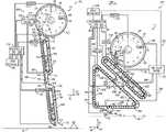
- FIG. 3is a side view of an embodiment of a particle delivery system 40 that may be employed within the row unit of FIG. 2 .
- the particle delivery system 40is configured to meter and accelerate particles 80 (e.g., seeds, fertilizer, other particulate material, or a combination thereof) toward the trench 31 for deposition into the trench 31 .
- particles 80e.g., seeds, fertilizer, other particulate material, or a combination thereof
- the particle delivery system 40includes a particle disc 82 (e.g., of the particle metering and singulation unit 44 ) configured to meter the particles 80 , a first particle belt 84 (e.g., an endless member) configured to accelerate and move the particles 80 to a second particle belt 86 (e.g., an endless member), and the second particle belt 86 configured to accelerate and move the particles 80 toward the trench 31 .
- a particle disc 82e.g., of the particle metering and singulation unit 44
- a first particle belt 84e.g., an endless member
- second particle belt 86e.g., an endless member
- the particle disc 82has apertures 90 configured to receive the particles 80 from a particle hopper 92 of the particle delivery system 40 .
- each aperture 90may receive a single particle 80 .
- the particle hopper 92is a particle storage area configured to store the particles 80 for subsequent metering and distribution.
- the particle hopper 92may be coupled to and/or included as part of a housing of the particle metering and singulation unit 44 .
- the hopper assemblymay provide the particles 80 to the particle hopper 92 , and/or the hopper assembly (e.g., the hopper of the hopper assembly) may be coupled to the particle hopper 92 .
- the particle disc 82is configured to rotate, as indicated by arrow 94 , to move the particles 80 from the particle hopper 92 to a release point 96 , where the particles 80 are released such that the particles 80 move downwardly toward the first particle belt 84 .
- the first particle belt 84is configured to rotate, as indicated by arrow 97 , to move the particles 80 to the second particle belt 86 .
- the second particle belt 86is configured to rotate, as indicated by arrows 98 , to expel the particles 80 into the trench 31 .
- the disc 82 having the apertures 90may be any suitable shape configured to rotate/move to transfer the particles 80 from the particle hopper 92 to the release point 96 .
- the disc 82may be generally flat, may have a curved portion and a flat portion, may be entirely curved, may be a drum, or may include other suitable shapes, geometries, and/or configurations.
- an inner portion of the disc 82may curved/raised related to an outer portion of the disc 82 having the apertures 90 (e.g., the disc 82 may be generally bowl-shaped), such that the particles 80 may be directed toward the apertures 90 (e.g., away from the raised inner portion and/or toward the flat outer portion) as the disc 82 rotates.
- the disc 82may be a drum having the apertures 90 disposed along an outer portion and/or an exterior of the drum.
- the particle delivery system 40includes an air flow system 100 having an air flow device 102 , a first air tube 104 fluidly coupled to the air flow device 102 , a second air tube 106 fluidly coupled to the air flow device 102 , and a third air tube 108 fluidly coupled to the air flow device 102 .
- the air flow system 100is configured to reduce the air pressure within a vacuum passage 110 positioned along a portion of the particle disc 82 , thereby drawing the particles 80 from the particle hopper 92 toward and against the apertures 90 .
- the first air tube 104is fluidly coupled to the air flow device 102 and to the vacuum passage 110 .
- the air flow device 102is configured to draw air through the apertures 90 aligned with the vacuum passage 110 , via the first air tube 104 .
- the vacuum formed at the apertures 90secures the particles 80 to the particle disc 82 at the apertures 90 , such that the particle disc 82 moves each particle 80 from the particle hopper 92 to the release point 96 .
- the air flow system 100provides, via the second air tube 106 , a first air flow 112 configured to remove each particle 80 from the respective aperture 90 (e.g., by overcoming the vacuum formed at the respective aperture 90 ).
- the first air flow 112may be omitted, and the particles 80 may be released from the apertures 90 due to the vacuum passage 110 ending.
- the vacuum passage 110may end (e.g., the air flow device 102 may no longer draw air through the apertures 90 of the particle disc 82 at the release point 96 ), and the particles 80 may no longer be secured in the apertures 90 .
- the particles 80are released from the particle disc 82 along a release trajectory 114 . Rotation of the particle disc 82 imparts a velocity on the particles along the release trajectory 114 , and the particles 80 accelerate downwardly along the release trajectory 114 under the influence of gravity.
- an angle between the release trajectory 114 and the vertical axis 62may be zero degrees, one degree, two degrees, five degrees, ten degrees, twenty degrees, or other suitable angles.
- vacuumrefers to an air pressure that is less than the ambient atmospheric air pressure, and not necessarily 0 pa.
- the particle delivery system 40includes a disc housing 120 , a first belt housing 122 , and a second belt housing 124 .
- the particle disc 82is disposed within and configured to rotate within the disc housing 120 .
- the first particle belt 84is disposed within and configured to rotate within the first belt housing 122 .
- the second particle belt 86is disposed within and configured to rotate within the second belt housing 124 .
- the vacuum passage 110 of the particle metering and singulation unit 44 and the particle hopper 92e.g., the particle storage area
- the particle metering and singulation unit 44includes the particle disc 82 and the disc housing 120 .
- the first belt housing and the second belt housingmay be a single belt housing, such that both the first particle belt and the second particle belt may be disposed within and configured to rotate within the single belt housing.
- the particle delivery system 40includes a particle tube 130 coupled to the disc housing 120 and the first belt housing 122 .
- the particle tube 130extends generally from the release point 96 to a particle engagement section 132 (e.g., a first particle engagement section) of the first particle belt 84 and is configured to at least partially direct the particles 80 from the particle disc 82 (e.g., from the release point 96 of the particle disc 82 ) to the first particle belt 84 (e.g., to the particle engagement section 132 of the first particle belt 84 ) along the release trajectory 114 .
- the particle tubemay include any suitable shape and/or configuration configured to at least particle direct the particles, such as a channel, a cylindrical tube, a rectangular tube, and/or other suitable shapes/configurations.
- the particle tubee.g., particle channel
- the particle tubemay be integrally formed with the disc housing and/or the first belt housing.
- the particle tubemay be omitted, such that the particles flow from the release point to the engagement point without guidance from the particle tube.
- the first particle belt 84includes the particle engagement section 132 and a particle exit section 134 (e.g., a first particle exit section) at generally opposite end portions of the first particle belt 84 .
- the particle engagement section and/or the particle exit sectionmay be at other portions of the first particle belt, such as a side portion extending between the end portions of the first particle belt.
- the first particle belt 84is configured to receive the particles 80 from the particle metering and singulation unit 44 at the particle engagement section 132 and to expel the particles 80 toward the second particle belt 86 along a transfer trajectory 136 at the particle exit section 134 .
- the second particle belt 86includes a particle engagement section 138 (e.g., a second particle engagement section) and a particle exit section 140 (e.g., a second particle engagement section) at generally opposite end portions of the second particle belt 86 .
- the particle engagement section and/or the particle exit sectionmay be at other portions of the second particle belt, such as a side portion extending between the end portions of the second particle belt.
- the second particle belt 86is configured to receive the particles 80 from the first particle belt 84 at the particle engagement section 138 and to expel the particles 80 to the trench 31 in soil at the particle exit section 140 and along a release trajectory 142 .
- the first particle belt 84includes a base 150 (e.g., a first base) and flights 152 (e.g., first flights) coupled to and extending from the base 150
- the second particle belt 86includes a base 154 (e.g., a second base) and flights 156 (e.g., second flights) coupled to and extending from the base 154 .
- Each pair of opposing flights 152 of the first particle belt 84is configured to receive a respective particle 80 at the particle engagement section 132 of the first particle belt 84 and to move the respective particle 80 to the particle exit section 134 of the first particle belt 84
- each pair of opposing flights 156 of the second particle belt 86is configured to receive a respective particle 80 at the particle engagement section 138 of the second particle belt 86 and to move the respective particle 80 to the particle exit section 140 of the second particle belt 86 .
- the particle delivery system 40includes a particle transfer assembly 160 configured to facilitate transfer of the particles 80 from the particle exit section 134 of the first particle belt 84 to the particle engagement section 138 of the second particle belt 86 .
- the particle transfer assembly 160includes a particle tube 162 configured to at least partially direct the particles 80 from the particle exit section 134 to the particle engagement section 138 to facilitate transferring the particles 80 .
- the particle tube 162is coupled to and extends between the first belt housing 122 and the second belt housing 124 .
- the air flow system 100is configured to provide a second air flow 164 from the third air tube 108 and toward the particle tube 162 to accelerate the particles 80 downwardly along the transfer trajectory 136 into the particle tube 162 (e.g., the air flow system 100 may apply a force to the particles 80 via the second air flow 164 ).
- the air flow system 100may provide the second air flow 164 into and/or through the particle tube 162 .
- the particle delivery system 40is configured to enable the particles 80 to accelerate under the influence of gravity as the particles 80 travel between the first particle belt and the second particle belt 86 (e.g., through the particle tube 162 ).
- the air flow system or portion(s) of the air flow systemmay be included from the particle transfer assembly.
- the particle transfer assemblymay include the air flow device, the third air tube, the second air flow provided via the third air tube, or a combination thereof.
- the particle disc 82is configured to meter the particles 80 and to provide a spacing between the particles 80 . Establishing a target spacing between the particles 80 when disposed within the trench 31 may enhance plant development and/or yield. Additionally, the particle delivery system 40 is configured to accelerate the particles 80 generally toward and along the trench 31 . The acceleration of the particles 80 by the particle delivery system 40 may reduce a relative ground speed of the particles 80 compared to traditional row units that utilize seed tubes which rely solely on gravity to accelerate the particles 80 for delivery to soil. For example, the particle delivery system 40 is configured to accelerate the particles 80 via the air flow system 100 , gravity, the first particle belt 84 , and the second particle belt 86 .
- the air flow system 100is configured to provide the first air flow 112 from the second air tube 106 to accelerate the particles 80 downwardly along the release trajectory 114 (e.g., the air flow system 100 may apply a force to the particles 80 via the first air flow 112 ).
- the particle delivery system 40is configured to enable the particles 80 to accelerate under the influence of gravity as the particles 80 travel between the particle disc 82 and the first particle belt 84 .
- the first particle belt 84is configured to accelerate the particles 80 received from the particle disc 82 , such that a particle transfer speed of the particles 80 expelled from the first particle belt 84 along the transfer trajectory 136 toward the particle engagement section 138 of the second particle belt 86 reaches a target particle transfer speed at the particle engagement section 138 .
- the second air flow 164 of the particle transfer assembly 160may accelerate the particles 80 , such that the particle transfer speed reaches the target particle transfer speed.
- the particle transfer speed of the particles 80may reach the target particle transfer speed when the particle transfer speed is equal to the target particle transfer speed, when the particle transfer speed passes (e.g., becomes greater than or less than) the target particle transfer speed, or when the particle transfer speed is within a threshold range of the target particle transfer speed (e.g., when a difference between the particle transfer speed and the target particle transfer speed is less than a threshold value associated with the threshold range).
- the second particle belt 86is configured to accelerate the particles 80 received from the first particle belt 84 , such that a particle exit speed of the particles 80 expelled from the second particle belt 86 along the release trajectory 142 toward the trench 31 reaches a target particle exit speed.
- the particle exit speed of the particles 80may reach the target particle exit speed when the particle exit speed is equal to the target particle exit speed, when the particle exit speed passes (e.g., becomes greater than or less than) the target particle exit speed, or when the particle exit speed is within a threshold range of the target particle exit speed (e.g., when a difference between the particle exit speed and the target particle exit speed is less than a threshold value associated with the threshold range).
- the second particle belt 86is configured to rotate faster than the first particle belt 84 to accelerate the particles 80 .
- the first particle belt 84may rotate at a first belt speed
- the second particle belt 86may rotate at a second belt speed, faster than the first belt speed (e.g., the target particle exit speed may be greater than the target particle transfer speed).
- the first belt speed of the first particle belt 84may be generally equal to the second belt speed of the second particle belt 86 (e.g., the target particle transfer speed may be generally equal to the target particle exit speed).
- the particle delivery systemmay include additional particle belts (e.g., in addition to the first particle belt 84 and the second particle belt 86 ) configured to accelerate the particles toward and/or along the trench.
- Each particle belt(from the particle belt adjacent to the hopper to the particle belt adjacent to the trench) may rotate progressively faster, such that each progressive particle belt imparts a greater velocity on each particle as the particle is released from the respective particle belt.
- the particle delivery system 40includes a controller 170 configured to control the rotation rate (e.g., the rotational speed) of the particle disc 82 to adjust/control the spacing between the particles 80 .
- the controller 170may control a motor 172 , which is configured to drive rotation of the particle disc 82 , to adjust/control the rotation rate of the particle disc 82 (e.g., by outputting an output signal to the motor 172 indicative of instructions to adjust the rotation rate of the particle disc 82 ).
- the controller 170may control the motor 172 to achieve a target spacing between the particles 80 .
- the controller 170may determine the target spacing between the particles 80 based on a type of the particles 80 , a size of the particles 80 (e.g., a nominal size and/or an average size of each particle), an input received from a user interface, or a combination thereof.
- the spacingmay be any suitable spacing, such as one centimeter, two centimeters, five centimeters, ten centimeters, fifty centimeters, one meter, two meters, five meters, etc.
- the controller 170may control the rotation rate of the particle disc 82 (e.g., via control of the motor 172 ) to achieve the target spacing based on a reference table identifying rotational speeds of the particle disc 82 that will achieve particular spacings, based on an empirical formula, in response to sensor feedback, or a combination thereof.
- the controller 170is configured to control the first air flow 112 provided by the air flow system 100 to adjust/control a particle transfer speed of each particle 80 expelled from the particle disc 82 (e.g., from the release point 96 of the particle disc 82 , along the release trajectory 114 , and toward the particle engagement section 132 of the first particle belt 84 ), such that the particle transfer speed reaches a target particle transfer speed at the particle engagement section 132 .
- the controller 170may control the air flow device 102 , which is configured to provide the first air flow 112 to accelerate each particle 80 along the release trajectory 114 .
- the controller 170may control a valve configured to adjust a flow rate of the first air flow 112 .
- the controller 170may determine the target particle transfer speed of the particles 80 based on the belt speed of the first particle belt 84 and/or the type of the particles 80 .
- the target particle transfer speedmay be any suitable speed, such one-tenth kph, one-half kph, one kph, two kph, three kph, five kph, ten kph, fifteen kph, twenty kph, etc.
- the controller 170may determine the target particle transfer speed as a target percentage of the belt speed of the first particle belt 84 (e.g., thirty percent, fifty percent, seventy percent, eighty percent, ninety percent, ninety-five percent, etc.).
- the controller 170may receive an input signal indicative of the particle transfer speed of the particle 80 at the particle engagement section 132 of the first particle belt 84 .
- the controller 170may receive the input signal from a particle sensor 178 of the particle delivery system 40 disposed within the particle tube 130 .
- the particle sensor 178may include an infrared sensor or another suitable type of sensor configured to output the input signal indicative of the particle transfer speed of each particle 80 at the particle engagement section 132 .
- the particle sensor 178may be positioned a fixed distance from the particle engagement section 132 , such that the controller 170 may determine the particle transfer speed of the particle 80 at the particle engagement section 132 based on the fixed distance and the input signal indicative of the particle transfer speed received from the particle sensor 178 (e.g., based on gravitational acceleration of the particle 80 traveling the fixed distance from the particle sensor 178 to the particle engagement section 132 and/or based on acceleration due to the first air flow 112 ).
- the controller 170may compare the particle transfer speed of the particle 80 at the particle engagement section 132 to the target particle transfer speed to determine whether a difference between the particle transfer speed and the target particle transfer speed exceeds a threshold value. In response to determining that the particle transfer speed at the particle engagement section 132 is less than the target particle transfer speed and the difference between the particle transfer speed and the target particle transfer speed exceeds the threshold value, the controller 170 may output an output signal indicative of instructions to increase the flow rate of the first air flow 112 provided by the air flow system 100 through the second air tube 106 . For example, the controller 170 may output the output signal to the air flow device 102 to cause the air flow device 102 to increase the flow rate of the first air flow 112 . The increase in the air flow rate may increase the particle transfer speed, such that the particle transfer speed reaches the target particle transfer speed (e.g., such that the difference between the particle transfer speed and the target particle transfer speed is less than the threshold value).
- the controller 170may output an output signal indicative of instructions to decrease the flow rate of the first air flow 112 provided by the air flow system 100 .
- the controller 170may output the output signal to the air flow device 102 to cause the air flow device 102 to decrease the flow rate of the first air flow 112 .
- the decrease in the air flow ratemay decrease the particle transfer speed, such that the particle transfer speed reaches the target particle transfer speed (e.g., such that the difference between the particle transfer speed and the target particle transfer speed is less than the threshold value).
- the controller 170is configured to control the belt speed of the first particle belt 84 to adjust/control the particle transfer speed of the particles 80 expelled from the particle exit section 134 of the first particle belt 84 , such that the particle transfer speed reaches a target particle transfer speed at the particle engagement section 138 of the second particle belt 86 .
- the controller 170may control a wheel 174 , via a motor 176 which is configured to drive rotation of the first particle belt 84 , to adjust/control the belt speed of the first particle belt 84 (e.g., by outputting an output signal to the motor 176 indicative of instructions to adjust the belt speed of the first particle belt 84 ), thereby enabling the controller 170 to adjust/control the particle transfer speed of the particles 80 .
- the controller 170may control the particle transfer speed of the particles 80 , such that the particle transfer speed reaches the target particle transfer speed.
- the controller 170may determine the target particle transfer speed of the particles 80 based on the type of the particles 80 , a size of the particles 80 (e.g., a nominal size and/or an average size of each particle), an input received from a user interface, the ground speed of the row unit, or a combination thereof.
- the target particle transfer speedmay be any suitable speed, such one kilometer per hour (kph), two kph, three kph, five kph, ten kph, fifteen kph, twenty kph, etc.
- the controller 170may determine the target particle transfer speed as a target percentage of a belt speed of the second particle belt 86 (e.g., a second belt speed) or of the ground speed of the row unit (e.g., thirty percent, fifty percent, seventy percent, eighty percent, ninety percent, ninety-five percent, etc.).
- the controller 170may receive an input signal indicative of the particle transfer speed of the particle 80 at the particle engagement section 138 of the second particle belt 86 .
- the controller 170may receive the input signal from a particle sensor 180 of the particle delivery system 40 disposed proximate to the particle engagement section 138 and along the transfer trajectory 136 .
- the particle sensor 180may include an infrared sensor or another suitable type of sensor configured to output the input signal indicative of the particle transfer speed of each particle 80 at the particle engagement section 138 .
- the particle sensor 180may be positioned a fixed distance from the particle engagement section 138 , such that the controller 170 may determine the particle transfer speed of the particle 80 at the particle engagement section 138 based on the fixed distance and the input signal indicative of the particle transfer speed received from the particle sensor 180 (e.g., based on acceleration and/or deceleration of the particle 80 traveling the fixed distance and/or based on acceleration due to the second air flow 164 ). As illustrated, the particle sensor 180 is disposed within the particle tube 162 . In certain embodiments, the particle sensor may be partially or entirely disposed with the first belt housing or the second belt housing.
- the controller 170may compare the particle transfer speed of the particle 80 at the particle engagement section 138 to the target particle transfer speed to determine whether a difference between the particle transfer speed and the target particle transfer speed exceeds a threshold value. In response to determining that the particle transfer speed at the particle engagement section 138 is less than the target particle transfer speed and the difference between the particle transfer speed and the target particle transfer speed exceeds the threshold value, the controller 170 may output an output signal indicative of instructions to increase the belt speed of the first particle belt 84 . For example, the controller 170 may output the output signal to the motor 176 to cause the motor 176 to increase the belt speed of the first particle belt 84 . The increase in the belt speed of the first particle belt 84 may increase the particle transfer speed, such that the particle transfer speed reaches the target particle transfer speed (e.g., such that the difference between the particle transfer speed and the target particle transfer speed is less than the threshold value).
- the controller 170may output an output signal indicative of instructions to decrease the belt speed of the first particle belt 84 .
- the controller 170may output the output signal to the motor 176 to cause the motor 176 to decrease the belt speed of the first particle belt 84 .
- the decrease in the belt speed of the first particle belt 84may decrease the particle transfer speed, such that the particle transfer speed reaches the target particle transfer speed (e.g., such that the difference between the particle transfer speed and the target particle transfer speed is less than the threshold value).
- the controller 170is configured to control the second air flow 164 provided by the air flow system 100 , to adjust/control the particle transfer speed of the particles 80 expelled from the particle exit section 134 of the first particle belt 84 , such that the particle transfer speed reaches the target particle transfer speed (e.g., in addition to or as an alternative to controlling the first belt speed of the first particle belt 84 ).
- the controller 170may control the second air flow 164 by outputting an output signal to the air flow device 102 indicative of instructions to adjust a flow rate of the second air flow 164 , thereby enabling the controller 170 to adjust/control the particle transfer speed of the particles 80 .
- the controller 170may compare the particle transfer speed of the particle 80 at the particle engagement section 138 to the target particle transfer speed to determine whether a difference between the particle transfer speed and the target particle transfer speed exceeds a threshold value. In response to determining that the particle transfer speed at the particle engagement section 138 is less than the target particle transfer speed and the difference between the particle transfer speed and the target particle transfer speed exceeds the threshold value, the controller 170 may output an output signal indicative of instructions to increase the flow rate of the second air flow 164 . For example, the controller 170 may output the output signal to the air flow device 102 to cause the air flow device 102 to increase the flow rate of the second air flow 164 . The increase in the flow rate of the second air flow 164 may increase the particle transfer speed, such that the particle transfer speed reaches the target particle transfer speed.
- the controller 170may output an output signal indicative of instructions to decrease the flow rate of the second air flow 164 .
- the controller 170may output the output signal to the air flow device 102 to cause the air flow device 102 to decrease the flow rate of the second air flow 164 .
- the decrease in the flow rate of the second air flow 164may decrease the particle transfer speed, such that the particle transfer speed reaches the target particle transfer speed.
- controller 170is configured to control the belt speed of the second particle belt 86 to adjust/control the particle exit speed of the particles 80 expelled from the second particle belt 86 (e.g., from the particle exit section 140 of the second particle belt 86 , along the release trajectory 142 , and toward and/or along the trench 31 ), such that the particle exit speed reaches a target particle exit speed.
- the controller 170may control a wheel 182 , via a motor 184 which is configured to drive rotation of the second particle belt 86 , to adjust/control the belt speed of the second particle belt 86 (e.g., by outputting an output signal to the motor 184 indicative of instructions to adjust the belt speed of the second particle belt 86 ), thereby enabling the controller 170 to adjust/control the particle exit speed of the particles 80 .
- the controller 170may control the particle exit speed of the particles 80 , such that the particle exit speed reaches the target particle exit speed.
- the controller 170may determine the target particle exit speed of the particles 80 based on the type of the particles 80 , a size of the particles 80 (e.g., a nominal size and/or an average size of each particle), an input received from a user interface, the ground speed of the row unit, or a combination thereof.
- the target particle exit speedmay be any suitable speed, such one kilometer per hour (kph), two kph, three kph, five kph, ten kph, fifteen kph, twenty kph, etc.
- the controller 170may determine the target particle exit speed as a target percentage of the ground speed of the row unit (e.g., thirty percent, fifty percent, seventy percent, eighty percent, ninety percent, ninety-five percent, one hundred percent, etc.).
- the controller 170may receive an input signal indicative of the particle exit speed of the particle 80 at the particle exit section 140 of the second particle belt 86 .
- the controller 170may receive the input signal from a particle sensor 186 of the particle delivery system 40 disposed proximate to the particle exit section 140 and along the release trajectory 142 .
- the particle sensor 186may include an infrared sensor or another suitable type of sensor configured to output the input signal indicative of the particle exit speed of each particle 80 at the particle exit section 140 .
- the particle sensor 186may be positioned a fixed distance from the particle exit section 140 , such that the controller 170 may determine the particle exit speed of the particle 80 at the particle exit section 140 based on the fixed distance and the input signal indicative of the particle exit speed received from the particle sensor 186 (e.g., based on acceleration and/or deceleration of the particle 80 traveling the fixed distance).
- the particle sensor 186may be configured output a signal indicative of the ground speed of the agricultural row unit to the controller 170 , and/or the controller 170 may receive the signal indicative of the ground speed from another source.
- the particle sensor 178 , the particle sensor 180 , the particle sensor 186 , or a combination thereofmay be omitted from the particle delivery system 40 .
- the controller 170may compare the particle exit speed of the particle 80 at the particle exit section 140 to the target particle exit speed to determine whether a difference between the particle exit speed and the target particle exit speed exceeds a threshold value. In response to determining that the particle exit speed at the particle exit section 140 is less than the target particle exit speed and the difference between the particle exit speed and the target particle exit speed exceeds the threshold value, the controller 170 may output an output signal indicative of instructions to increase the belt speed of the second particle belt 86 . For example, the controller 170 may output the output signal to the motor 184 to cause the motor 184 to increase the belt speed of the second particle belt 86 . The increase in the belt speed of the second particle belt 86 may increase the particle exit speed, such that the particle exit speed reaches the target particle exit speed (e.g., such that the difference between the particle exit speed and the target particle exit speed is less than the threshold value).
- the controller 170may output an output signal indicative of instructions to decrease the belt speed of the second particle belt 86 .
- the controller 170may output the output signal to the motor 184 to cause the motor 184 to decrease the belt speed of the second particle belt 86 .
- the decrease in the belt speed of the second particle belt 86may decrease the particle exit speed, such that the particle exit speed reaches the target particle exit speed (e.g., such that the difference between the particle exit speed and the target particle exit speed is less than the threshold value).
- the controller 170 of the particle delivery system 40includes a processor 190 and a memory 192 .
- the processor 190e.g., a microprocessor
- the processor 190may be used to execute software, such as software stored in the memory 192 for controlling the particle delivery system 40 (e.g., for controlling the rotation rate of the particle disc 82 , the belt speeds of the first particle belt 84 and the second particle belt 86 , and the first air flow 112 and the second air flow 164 provided by the air flow system 100 , etc.).
- the processor 190may include multiple microprocessors, one or more “general-purpose” microprocessors, one or more special-purpose microprocessors, and/or one or more application specific integrated circuits (ASICS), or some combination thereof.
- the processor 190may include one or more reduced instruction set (RISC) or complex instruction set (CISC) processors.
- RISCreduced instruction set
- CISCcomplex instruction set
- the memory device 192may include a volatile memory, such as random access memory (RAM), and/or a nonvolatile memory, such as read-only memory (ROM).
- the memory device 192may store a variety of information and may be used for various purposes.
- the memory device 192may store processor-executable instructions (e.g., firmware or software) for the processor 190 to execute, such as instructions for controlling the particle delivery system 40 .
- the controller 170may also include one or more storage devices and/or other suitable components.
- the storage device(s)e.g., nonvolatile storage
- the storage device(s)may store data (e.g., the target particle transfer speed(s) and the target particle exit speed), instructions (e.g., software or firmware for controlling the particle delivery system 40 ), and any other suitable data.
- the processor 190 and/or the memory device 192 , and/or an additional processor and/or memory device,may be located in any suitable portion of the system.
- a memory device for storing instructionse.g., software or firmware for controlling portions of the particle delivery system 40
- the particle delivery system 40includes a user interface 194 that is communicatively coupled to the controller 170 .
- the user interface 194may be configured to inform an operator of the particle transfer speed(s) of the particles 80 , the particle exit speed of the particles 80 , to enable the operator to adjust the rotation rate of the particle disc 82 and/or the spacing between the particles 80 , to enable the operator to adjust the belt speeds of the first particle belt 84 and the second particle belt 86 and/or the acceleration of the particles 80 , to enable the operator to adjust the first air flow 112 and the second air flow 164 provided by the air flow system 100 , to provide the operator with selectable options of the type of particles 80 , and to enable other operator interactions.
- the user interface 194may include a display and/or other user interaction devices (e.g., buttons) configured to enable operator interactions.
- the controller 170may determine other information related to the particles 80 based on feedback from the sensor 186 , such as skips (e.g., the particle 80 not being present during an expected time period), multiple particles 80 (e.g., multiple particles 80 being present when only a single particle 80 is expected), an amount of particles 80 deposited over a given area (e.g., an amount of particles 80 deposited per acre), and other information related to the particles 80 .
- the controller 170may control the particle delivery system based on such determinations.
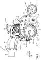
- FIG. 4is a side view of another embodiment of a particle delivery system 200 that may be employed within the row unit of FIG. 2 .
- the particle delivery system 200includes the particle metering and singulation unit 44 , which includes the particle disc 82 , configured to meter and establish the spacing between the particles 80 .
- the particle delivery system 200also includes the first particle belt 84 configured to receive the particles from the particle metering and singulation unit 44 and to expel the particles 80 to the second particle belt 86 .
- the particle delivery system 200includes the second particle belt 86 configured to receive the particles 80 from the first particle belt 84 and to expel the particles 80 to the trench 31 .
- the particle delivery system 200includes the air flow system 100 configured to provide the vacuum along the vacuum passage 110 adjacent to the particle disc 82 , and to remove the particles 80 from the particle disc 82 and accelerate the particles 80 along the release trajectory 114 using the first air flow 112 .
- the particle delivery system 200includes a particle transfer assembly 202 disposed generally between the particle exit section 134 of the first particle belt 84 and the particle engagement section 138 of the second particle belt 86 .
- the particle transfer assembly 202includes a particle transfer housing 204 coupled to the first belt housing 122 and to the second belt housing 124 .
- the particle transfer assembly 202is configured to accelerate and at least partially direct the particles 80 toward the particle engagement section 138 along a transfer trajectory 206 .
- the particle transfer assembly 202includes guide wheels 210 configured to rotate (e.g., in opposite directions) to drive the particles 80 downwardly along the transfer trajectory 206 .
- each guide wheel 210includes a wheel base 212 (e.g., a wheel, a gear, etc.) and paddles 214 coupled to the wheel base 212 .
- the wheel base 212is configured to rotate to drive rotation of the paddles 214 .
- the paddles 214are configured to contact the particles 80 flowing between the guide wheels 210 . As a paddle 214 contacts a respective particle 80 , the paddle 214 directs the particle 80 along the transfer trajectory 206 . Additionally, the paddles 214 are configured to accelerate the particles 80 , such that the particle transfer speed of the particles 80 reaches the target particle transfer speed.
- the paddles 214may be formed from a resilient and flexible material (e.g., rubber, plastic, fabric, other materials, or a combination thereof) that enables the paddles 214 to flex in response to contact with the particles 80 and/or in response to rotation of the guide wheels 210 .
- the particle delivery systemmay include more or fewer guide wheels disposed generally between the particle discs and configured to guide and to accelerate the particles along the transfer trajectory (e.g., zero guide wheels, one guide wheel, three guide wheels, four guide wheels, six guide wheels, ten guide wheels, etc.).
- the controller 170is configured to control a rotation rate of the guide wheels 210 to adjust/control the particle transfer speed of the particles 80 along the transfer trajectory 206 and toward the particle engagement section 138 of the second particle belt 86 , such that the particle transfer speed reaches a target particle transfer speed at the particle engagement section 138 .
- the controller 170may receive an input signal indicative of the particle transfer speed of the particle 80 at the particle engagement section 138 .
- the controller 170may receive the input signal from the particle sensor 180 of the particle delivery system 40 disposed within the particle transfer housing 204 proximate to the guide wheels 210 .
- the particle sensor 180may be positioned a fixed distance from the particle engagement section 138 , such that the controller 170 may determine the particle transfer speed of the particle 80 at the particle engagement section 138 based on the fixed distance and the input signal indicative of the particle transfer speed received from the particle sensor 180 .
- the controller 170may compare the particle transfer speed of the particle 80 at the particle engagement section 138 to the target particle transfer speed to determine whether a difference between the particle transfer speed and the target particle transfer speed exceeds a threshold value. In response to determining that the particle transfer speed at the particle engagement section 138 is less than the target particle transfer speed and the difference between the particle transfer speed and the target particle transfer speed exceeds the threshold value, the controller 170 may output an output signal indicative of instructions to increase the rotation rate of the guide wheels 210 . For example, the controller 170 may output the output signal to a motor 216 of the particle delivery system 200 coupled to and configured to drive rotation of the wheel base 212 of each guide wheel 210 to cause the motor 216 to increase the rotation rate of each guide wheel 210 .
- the increase in the rotation rate of the guide wheels 210may increase the particle transfer speed, such that the particle transfer speed reaches the target particle transfer speed (e.g., such that the difference between the particle transfer speed and the target particle transfer speed is less than the threshold value).
- the particle delivery systemmay include an additional motor (e.g., two motors) with each motor configured to drive rotation of a respective guide wheel.
- the controllermay control each motor to control the rotation rate of each guide wheel.
- the controller 170may output an output signal indicative of instructions to decrease the rotation rate of the guide wheels 210 .
- the controller 170may output the output signal to the motor 216 to cause the motor 216 to decrease the rotation rate of each guide wheel 210 .
- the decrease in the rotation rate of the guide wheels 210may decrease the particle transfer speed, such that the particle transfer speed reaches the target particle transfer speed (e.g., such that the difference between the particle transfer speed and the target particle transfer speed is less than the threshold value).
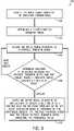
- FIG. 5is a flow diagram of an embodiment of a process 220 for controlling a particle delivery system.
- the process 220may be performed by the controller of the particle delivery system.
- the process 220begins at block 222 , in which an input signal indicative of operating parameter(s) is received.
- the operating parametersmay include the type of the particles, the ground speed of the row unit, a spacing between flights of one or more particle belts, a size of the particles, or a combination thereof.
- the input signalmay be received from the user interface communicatively coupled to the controller, may be stored in the memory of the controller, may be received via sensor(s) of the row unit and/or the agricultural implement, may be received from a transceiver, or a combination thereof.
- the target particle transfer speedis determined.
- the controllermay determine the target particle transfer speed of the particles based on the type of the particles, the belt speed of the second particle belt (e.g., the second particle belt having the particle engagement section configured to receive the particles traveling at the particle transfer speed), the spacing between flight of the second particle belt, the size of the particles, and/or other operating parameters.
- an input signal indicative of the particle transfer speed of the particle at the particle engagement section of the second particle beltis received.
- the controllermay receive the input signal indicative of the particle transfer speed from the particle sensor disposed proximate to the particle engagement section.
- the controllermay receive multiple input signals from the particle sensor, in which each input signal is indicative of a particle transfer speed of a respective particle.
- the controllermay determine an average of the multiple particle transfer speeds to determine the average particle transfer speed of the particles at the particle engagement section.
- the controllermay account for variance among the particle transfer speeds of multiple particles at the particle engagement section to reduce excessive control actions (e.g., adjustments to the belt speed of the first particle belt, the second air flow provided by the air flow system, the or rotation rate of the guide wheels, or a combination thereof).
- a determination of whether a difference between the particle transfer speed and the target particle transfer speed exceeds a threshold valueis made (e.g., by the controller). Additionally, a determination of whether the particle transfer speed is less than or greater than the target particle transfer speed is made (e.g., by the controller).
- the threshold valuemay be determined based on the type of the particles and/or the belt speed of the second particle belt.
- the process 220proceeds to block 230 .
- the process 220returns to block 226 and receives the next input signal indicative of the particle transfer speed.
- an output signal indicative of instructions to adjust the belt speed of the first particle belt, the second air flow provided by the air flow system, the rotation rate of the guide wheels, or a combination thereof,is output by the controller.
- the controllermay output the output signal indicative of instructions to increase the belt speed of the first particle belt in response to a determination that the particle transfer speed is less than the target particle transfer speed and the difference between the particle transfer speed and the target particle transfer speed exceeds the threshold value, or the controller may output the output signal indicative of instructions to decrease the belt speed of the first particle belt in response to a determination that the particle transfer speed is greater than the target particle transfer speed and the difference between the particle transfer speed and the target particle transfer speed exceeds the threshold value.
- the controllermay output the output signal indicative of instructions to increase the flow rate of the second air flow in response to the determination that the particle transfer speed is less than the target particle transfer speed and the difference between the particle transfer speed and the target particle transfer speed exceeds the threshold value, or the controller may output the output signal indicative of instructions to decrease the flow rate of the second air flow in response to the determination that the particle transfer speed is greater than the target particle transfer speed and the difference between the particle transfer speed and the target particle transfer speed exceeds the threshold value.
- the controllermay output the output signal indicative of instructions to increase the rotation rate of the guide wheels in response to the determination that the particle transfer speed is less than the target particle transfer speed and the difference between the particle transfer speed and the target particle transfer speed exceeds the threshold value, or the controller may output the output signal indicative of instructions to decrease the rotation rate of the guide wheels in response to the determination that the particle transfer speed is greater than the target particle transfer speed and the difference between the particle transfer speed and the target particle transfer speed exceeds the threshold value.
- the controllermay determine whether the particle transfer speed is within a first threshold value of the target particle transfer speed and whether the particle transfer speed is within a second threshold value of the target particle transfer speed. For example, in response to the difference between the particle transfer speed and the target particle transfer speed exceeding a first threshold value, the controller may perform a first control action, such as adjusting the belt speed of the first particle belt.
- the controllermay perform a second control action (e.g., in addition to or in place of the first control action), such as adjusting the flow rate of the second air flow provided by the air flow system and/or the rotation rate of the guide wheels.
- a second control actione.g., in addition to or in place of the first control action
- the process 220After completing block 230 , the process 220 returns to block 226 and receives the next input signal indicative of the particle transfer speed of the particle at the particle engagement section of the second particle belt.
- the next determinationis made of whether the difference between the particle transfer speed and the target particle transfer speed exceeds the threshold value (e.g., block 228 ), and the belt speed of the second particle belt, the flow rate of the second air flow, the rotation rate of the guide wheels, or the combination thereof, may be adjusted in response to the determination.
- blocks 226 - 230 of the process 220may be iteratively performed (e.g., by the controller of the particle delivery system and/or by another suitable controller) to facilitate acceleration of the particles to the target particle transfer speed and transfer of the particles between the first and second particle belts.
- certain blocks of the blocks 222 - 230may be omitted from the process 220 , and/or the order of the blocks 222 - 230 may be different.
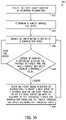
- FIG. 6is a flow diagram of an embodiment of a process 240 for controlling a particle delivery system.
- the process 240may be performed by the controller of the particle delivery system.
- the process 240begins at block 242 , in which an input signal indicative of operating parameter(s) is received.
- the operating parametersmay include the type of the particles, the ground speed of the row unit, a spacing between flights of one or more particle belts, a size of the particles, or a combination thereof.
- the input signalmay be received from the user interface communicatively coupled to the controller, may be stored in the memory of the controller, may be received via sensor(s) of the row unit and/or the agricultural implement, may be received from a transceiver, or a combination thereof.
- the target particle exit speedis determined.
- the controllermay determine the target particle exit speed of the particles based on the type of the particles, the ground speed of the row unit, the size of the particles, and/or other operating parameters.
- an input signal indicative of the particle exit speed of the particle at the particle exit section of the second particle beltis received.
- the controllermay receive the input signal indicative of the particle exit speed from the particle sensor disposed proximate to the particle exit section of the second particle belt.
- the controllermay receive multiple input signals from the particle sensor, in which each input signal is indicative of a particle exit speed of a respective particle.
- the controllermay determine an average of the multiple particle exit speeds to determine the average particle exit speed of the particles at the particle exit section. As such, the controller may account for variance among the particle exit speeds of multiple particles at the particle exit section to reduce excessive control actions (e.g., adjustments to the belt speed of the second particle belt).
- a determination of whether a difference between the particle exit speed and the target particle exit speed exceeds a threshold valueis made (e.g., by the controller). Additionally, a determination of whether the particle exit speed is less than or greater than the target particle exit speed is made (e.g., by the controller). The threshold value may be determined based on the type of the particles, the ground speed of the row unit, and/or other factors.
- the process 240proceeds to block 250 .
- the process 240returns to block 246 and receives the next input signal indicative of the particle exit speed.
- an output signal indicative of instructions to adjust the belt speed of the second particle beltis output to the motor configured to drive rotation of the second particle belt (e.g., the motor configured to drive rotation of the wheel coupled to and configured to drive rotation of the second particle belt).
- the controllermay output the output signal indicative of instructions to increase the belt speed of the second particle belt in response to a determination that the particle exit speed is less than the target particle exit speed and the difference between the particle exit speed and the target particle exit speed exceeds the threshold value.
- the controllermay output the output signal indicative of instructions to decrease the belt speed of the second particle belt in response to a determination that the particle exit speed is greater than the target particle exit speed and the difference between the particle exit speed and the target particle exit speed exceeds the threshold value.
- the process 240After completing block 250 , the process 240 returns to block 246 and receives the next input signal indicative of the particle exit speed of the particle at the particle exit section of the second particle belt.
- the next determinationis made of whether the difference between the particle exit speed and the target particle exit speed exceeds the threshold value (e.g., block 248 ), and the belt speed of the second particle belt may be adjusted in response to the determination.
- blocks 246 - 250 of the process 240may be iteratively performed (e.g., by the controller of the particle delivery system and/or by another suitable controller) to facilitate acceleration of the particles to the target particle exit speed.
- certain blocks of the blocks 242 - 250may be omitted from the process 240 , and/or the order of the blocks 242 - 250 may be different.
- FIG. 7is a side view of another embodiment of a particle delivery system 260 that may be employed within the row unit of FIG. 2 .
- the particle delivery system 260is configured to meter and accelerate the particles 80 toward the trench 31 for deposition into the trench 31 .
- the particle delivery system 260includes a particle disc 262 (e.g., of a particle metering and singulation unit 264 ) configured to meter the particles 80 and a particle belt 266 (e.g., an endless member) configured to receive the particles 80 from the particle disc 262 and to accelerate and move the particles 80 toward the trench 31 .
- a particle disc 262e.g., of a particle metering and singulation unit 264
- a particle belt 266e.g., an endless member
- the particle disc 262has apertures 268 configured to receive the particles 80 from a particle hopper 270 of the particle delivery system 260 .
- each aperture 268may receive a single particle 80 .
- the particle hopper 270is a particle storage area configured to store the particles 80 for subsequent metering and distribution.
- the particle hopper 270may be coupled to and/or included as part of a housing of the particle metering and singulation unit 264 .
- a hopper assemblymay provide the particles 80 to the particle hopper 270 , and/or the hopper assembly (e.g., the hopper of the hopper assembly) may be coupled to the particle hopper 270 .
- the particle disc 262is configured to rotate, as indicated by arrow 272 , to move the particles 80 from the particle hopper 270 to a release point 274 , where the particles 80 are released such that the particles 80 move downwardly toward the particle belt 266 along a transfer trajectory 276 .
- the particle belt 266is configured to rotate, as indicated by arrows 278 , to move the particles 80 toward the trench 31 and to expel the particles 80 into the trench 31 along a release trajectory 280 .
- the disc 262 having the apertures 268may be any suitable shape configured to rotate/move to transfer the particles 80 from the particle hopper 270 to the release point 274 .
- the disc 262may be generally flat, may have a curved portion and a flat portion, may be entirely curved, may be a drum, or may include other suitable shapes, geometries, and/or configurations.
- an inner portion of the disc 262may curved/raised related to an outer portion of the disc 262 having the apertures 268 (e.g., the disc 262 may be generally bowl-shaped), such that the particles 80 may be directed toward the apertures 268 (e.g., away from the raised inner portion and/or toward the flat outer portion) as the disc 262 rotates.
- the disc 262may be a drum having the apertures 268 disposed along an outer portion and/or an exterior of the drum.
- the particle delivery system 260includes an air flow system 290 having the air flow device 102 , a first air tube 292 fluidly coupled to the air flow device 102 , a second air tube 294 fluidly coupled to the air flow device 102 , and a third air tube 296 fluidly coupled to the air flow device 102 .
- the air flow system 290is configured to reduce the air pressure within a vacuum passage 298 positioned along a portion of the particle disc 262 , thereby drawing the particles 80 from the particle hopper 270 toward and against the apertures 268 .
- the first air tube 292is fluidly coupled to the air flow device 102 and to the vacuum passage 298 .
- the air flow device 102is configured to draw air through the apertures 268 aligned with the vacuum passage 298 , via the first air tube 292 .
- the vacuum formed at the apertures 268secures the particles 80 to the particle disc 262 at the apertures 268 , such that the particle disc 262 moves each particle 80 from the particle hopper 270 to the release point 274 .
- the air flow system 290provides, via the second air tube 294 , a first air flow 300 configured to remove each particle 80 from the respective aperture 268 (e.g., by overcoming the vacuum formed at the respective aperture 268 ).
- the first air flow 300may be omitted, and the particles 80 may be released from the apertures 268 due to the vacuum passage 298 ending.
- the vacuum passage 298may end (e.g., the air flow device 102 may no longer draw air through the apertures 268 of the particle disc 262 at the release point 274 ), and the particles 80 may no longer be secured in the apertures 268 .
- Rotation of the particle disc 82imparts a velocity on the particles 80 , and the particles 80 accelerate downwardly along the transfer trajectory 276 under the influence of gravity.
- an angle between the transfer trajectory 276 and the vertical axis 62may be zero degrees, one degree, two degrees, five degrees, ten degrees, twenty degrees, thirty degrees, forty-five degrees, sixty degrees, seventy-five degrees, eighty-five degrees, ninety degrees, or other suitable angles.
- vacuumrefers to an air pressure that is less than the ambient atmospheric air pressure, and not necessarily 0 pa.
- the particle delivery system 260includes a disc housing 310 and a belt housing 312 .
- the particle disc 262is disposed within and configured to rotate within the disc housing 310 .
- the particle belt 266is disposed within and configured to rotate within the belt housing 312 .
- the vacuum passage 298 of the particle metering and singulation unit 264 and the particle hopper 270are formed within the disc housing 310 .
- the particle metering and singulation unit 44includes the particle disc 262 and the disc housing 310 .
- the belt housing 312has a particle reception aperture 320 and a particle exit aperture 322 .
- the particle belt 266is configured to receive the particles 80 at a particle engagement section 324 of the particle belt 266 . Accordingly, the particles 80 flow from the release point 274 , along the transfer trajectory 276 , through the particle reception aperture 320 , and to the particle engagement section 324 .
- the air flow system 290may provide the first air flow 300 through the particle reception aperture 320 to accelerate the particles 80 from the particle disc 262 toward the particle belt 266 . Further, the particle belt 266 is configured to expel the particles 80 at a particle exit section 326 of the particle belt 266 .
- the air flow system 290is also configured to provide a second air flow 328 from the third air tube 296 to accelerate the particles 80 along the release trajectory 280 (e.g., the air flow system 290 may apply a force to the particles 80 via the second air flow 328 ).
- the air flow system 290provides the second air flow 328 through the particle exit aperture 322 to accelerate the particles 80 away from the particle exit section 326 of the particle belt 266 and toward the trench 31 .
- the air flow system or portion(s) of the air flow systemmay be omitted from the particle delivery system.
- the particle delivery systemmay only include the air flow device, the first air tube, and the third air tube.
- the air flow systemmay be entirely omitted from the particle delivery system.
- the particle belt 266includes a base 340 and flights 342 coupled to and extending from the base 340 . Each pair of opposing flights 342 of the particle belt 266 is configured to receive a respective particle 80 at the particle engagement section 324 and to move the respective particle 80 to the particle exit section 326 .
- the particle belt 266extends generally parallel to the trench 31 at the particle exit section 326 , which may facilitate deposition of the particles 80 into the trench 31 .
- a belt speed of the particle belt 266may be controlled to generally match a ground speed of the row unit having the particle delivery system 260 , which may enable the particles 80 to be deposited into the trench 31 at a speed (e.g., a speed relative to the trench 31 ) that is zero or that is negligible.
- the zero/negligible speed of the particles 80 relative to the trench 31may enable consistent placement of the particles 80 within the trench and/or a softer impact between the particles 80 and soil within the trench 31 .
- the particle belt at the particle exit sectionmay extend at an angle relative to the trench (e.g., one degree, two degrees, five degrees, ten degrees, twenty degrees, forty-five degrees, between zero degrees and five degrees, between zero degrees and ten degrees, between five degrees and twenty degrees, between ten degrees and forty-five degrees, etc.). Additionally, the particle belt 266 at the particle engagement section 324 extends at an angle 344 of about forty-five degrees relative to the particle belt 266 at the particle exit section 326 .
- the angle between the particle belt at the particle engagement section and the particle belt at the particle exit sectionmay be one degree, two degrees, five degrees, ten degrees, twenty degrees, thirty degrees, fifty degrees, sixty degrees, seventy-five degrees, between zero degrees and five degrees, between zero degrees and ten degrees, between five degrees and twenty degrees, between ten degrees and forty-five degrees, between thirty degrees and sixty degrees, between zero and ninety degrees, etc.
- the particle belt 266 at the particle engagement section 324 disposed at the angle 344may facilitate transfer of the particles 80 from the particle disc 262 to the particle belt 266 .
- the particle belt 266 at the particle engagement section 324 disposed at the angle 344may facilitate receipt of the particles 80 at the particle engagement section 324 .
- the particle disc 262is configured to meter the particles 80 and to provide a spacing between the particles 80 within the trench 31 .
- the spacing between the particles 80 when disposed within the trench 31may enhance plant development and/or yield.
- the particle delivery system 260is configured to accelerate the particles 80 generally toward and along the trench 31 .
- the acceleration of the particles 80 by the particle delivery system 260may enable the row unit to reduce a relative ground speed of the particles 80 compared to traditional row units that utilize seed tubes, which rely solely on gravity to accelerate the particles 80 for delivery to soil.
- the particle delivery system 260is configured to accelerate the particles 80 via the air flow system 290 , gravity, and the particle belt 266 .
- the air flow system 290is configured to accelerate the particles 80 via the first air flow 300 , such that a particle transfer speed of the particles 80 expelled from the particle disc 262 toward the particle engagement section 324 of the particle belt 266 reaches a target particle transfer speed at the particle engagement section 324 .
- the particle transfer speed of the particles 80may reach the target particle transfer speed when the particle transfer speed is equal to the target particle transfer speed, when the particle transfer speed passes (e.g., becomes greater than or less than) the target particle transfer speed, or when the particle transfer speed is within a threshold range of the target particle transfer speed.
- the particle belt 266is configured to accelerate the particles 80 received from the particle disc 262 , such that a particle exit speed of the particles 80 expelled from the particle belt 266 along the release trajectory 280 toward the trench 31 reaches a target particle exit speed.
- the particle exit speed of the particles 80may reach the target particle exit speed when the particle exit speed is equal to the target particle exit speed, when the particle exit speed passes the target particle exit speed, or when the particle exit speed is within a threshold range of the target particle exit speed (e.g., the difference between the particle exit speed and the target particle exit speed is less than a threshold value).
- the particle delivery system 260includes the controller 170 configured to control the rotation rate (e.g., the rotational speed) of the particle disc 262 to adjust/control the spacing between the particles 80 .
- the controller 170may control the motor 172 , which is configured to drive rotation of the particle disc 262 , to adjust/control the rotation rate of the particle disc 262 (e.g., by outputting an output signal to the motor 172 indicative of instructions to adjust the rotation rate of the particle disc 262 ).
- the controller 170may control the motor 172 to achieve a target spacing between the particles 80 .
- the controller 170may determine the target spacing between the particles 80 based on a type of the particles 80 , an input received from a user interface, or a combination thereof.
- the controller 170may control the rotation rate of the particle disc 262 (e.g., via control of the motor 172 ) to achieve the target spacing based on a reference table identifying rotational speeds of the particle disc 262 that achieve particular spacings, based on an empirical formula, in response to sensor feedback, or a combination thereof.
- the controller 170is configured to control the first air flow 300 provided by the air flow system 290 to adjust/control a particle transfer speed of each particle 80 expelled from the particle disc 262 (e.g., from the release point 274 of the particle disc 82 toward the particle engagement section 324 of the particle belt 266 ), such that the particle transfer speed reaches a target particle transfer speed at the particle engagement section 324 .
- the controller 170may control the air flow device 102 , which is configured to provide the first air flow 300 to accelerate each particle 80 along the transfer trajectory 276 .
- the controller 170may determine the target particle transfer speed of the particles 80 based on the belt speed of the particle belt 266 and/or the type of the particles 80 .
- the target particle transfer speedmay be any suitable speed, such one-tenth kph, one-half kph, one kph, two kph, three kph, five kph, ten kph, fifteen kph, twenty kph, etc.
- the controller 170may determine the target particle transfer speed as a target percentage of the belt speed of the particle belt 266 (e.g., thirty percent, fifty percent, seventy percent, eighty percent, ninety percent, ninety-five percent, etc.).
- the controller 170may receive an input signal indicative of the particle transfer speed of the particle 80 at the particle engagement section 324 of the particle belt 266 .
- the controller 170may receive the input signal from the particle sensor 178 of the particle delivery system 260 .
- the particle sensor 178may be positioned a fixed distance from the particle engagement section 324 , such that the controller 170 may determine the particle transfer speed of the particle 80 at the particle engagement section 324 based on the fixed distance and the input signal indicative of the particle transfer speed received from the particle sensor 178 (e.g., based on gravitational acceleration of the particle 80 traveling the fixed distance from the particle sensor 178 to the particle engagement section 324 and/or based on acceleration due to the first air flow 300 ).
- the controller 170may control valves configured to enable/restrict the first air flow 300 and/or the second air flow 328 (e.g., in addition or as an alternative to controlling the flow rates of the first air flow 300 and/or the second air flow 328 ).
- the controller 170may compare the particle transfer speed of the particle 80 at the particle engagement section 324 to the target particle transfer speed to determine whether a difference between the particle transfer speed and the target particle transfer speed exceeds a threshold value. In response to determining that the particle transfer speed at the particle engagement section 324 is less than the target particle transfer speed and the difference between the particle transfer speed and the target particle transfer speed exceeds the threshold value, the controller 170 may output an output signal indicative of instructions to increase the flow rate of the first air flow 300 from the second air tube 294 . For example, the controller 170 may output the output signal to the air flow device 102 to cause the air flow device 102 to increase the flow rate of the first air flow 300 . The increase in the air flow rate may increase the particle transfer speed, such that the particle transfer speed reaches the target particle transfer speed (e.g., such that the difference between the particle transfer speed and the target particle transfer speed is less than the threshold value).
- the controller 170may output an output signal indicative of instructions to decrease the flow rate of the first air flow 300 provided by the air flow system 290 .
- the controller 170may output the output signal to the air flow device 102 to cause the air flow device 102 to decrease the flow rate of the first air flow 300 .
- the decrease in the air flow ratemay decrease the particle transfer speed, such that the particle transfer speed reaches the target particle transfer speed (e.g., such that the difference between the particle transfer speed and the target particle transfer speed is less than the threshold value).
- the controller 170is configured to control the belt speed of the particle belt 266 to adjust/control the particle exit speed of the particles 80 expelled from the particle belt 266 , such that the particle exit speed reaches a target particle exit speed at the particle exit section 326 .
- the controller 170may control a wheel 350 , via the motor 176 which is configured to drive rotation of the particle belt 266 , to adjust/control the belt speed of the particle belt 266 (e.g., by outputting an output signal to the motor 176 indicative of instructions to adjust the belt speed of the particle belt 266 ), thereby enabling the controller 170 to adjust/control the particle exit speed of the particles 80 .
- the controller 170may control the particle exit speed of the particles 80 , such that the particle exit speed reaches the target particle exit speed.
- the controller 170may determine the target particle exit speed of the particles 80 based on the type of the particles 80 , an input received from a user interface, the ground speed of the row unit, or a combination thereof.
- the target particle exit speedmay be any suitable speed, such one kilometer per hour (kph), two kph, three kph, five kph, ten kph, fifteen kph, twenty kph, etc.
- the controller 170may determine the target particle exit speed as a target percentage of the ground speed of the row unit (e.g., thirty percent, fifty percent, seventy percent, eighty percent, ninety percent, ninety-five percent, one hundred percent, etc.).
- the controller 170may receive an input signal indicative of the particle exit speed of the particle 80 at the particle exit section 326 of the particle belt 266 .
- the controller 170may receive the input signal from the particle sensor 186 of the particle delivery system 260 disposed proximate to the particle exit section 326 and along the release trajectory 280 .
- the particle sensor 186may be positioned a fixed distance from the particle exit section 326 , such that the controller 170 may determine the particle exit speed of the particle 80 at the particle exit section 326 based on the fixed distance and the input signal indicative of the particle exit speed received from the particle sensor 186 (e.g., based on acceleration and/or deceleration of the particle 80 traveling the fixed distance).
- the controller 170may compare the particle exit speed of the particle 80 at the particle exit section 326 to the target particle exit speed to determine whether a difference between the particle exit speed and the target particle exit speed exceeds a threshold value. In response to determining that the particle exit speed at the particle exit section 326 is less than the target particle exit speed and the difference between the particle exit speed and the target particle exit speed exceeds the threshold value, the controller 170 may output an output signal indicative of instructions to increase the belt speed of the particle belt 266 . For example, the controller 170 may output the output signal to the motor 176 to cause the motor 176 to increase the belt speed of the particle belt 266 . The increase in the belt speed of the particle belt 266 may increase the particle exit speed, such that the particle exit speed reaches the target particle exit speed (e.g., such that the difference between the particle exit speed and the target particle exit speed is less than the threshold value).
- the controller 170may output an output signal indicative of instructions to decrease the belt speed of the particle belt 266 .
- the controller 170may output the output signal to the motor 176 to cause the motor 176 to decrease the belt speed of the particle belt 266 .
- the decrease in the belt speed of the particle belt 266may decrease the particle exit speed, such that the particle exit speed reaches the target particle exit speed (e.g., such that the difference between the particle exit speed and the target particle exit speed is less than the threshold value).
- the controller 170is configured to control the second air flow 328 provided by the air flow system 290 to adjust/control the particle exit speed of the particles 80 expelled from the particle belt 266 , such that the particle exit speed reaches the target particle exit speed.
- the controller 170may control the air flow device 102 , which is configured to provide the second air flow 328 to accelerate each particle 80 along the release trajectory 280 .
- the controller 170may receive the input signal indicative of the particle exit speed of the particle 80 at the particle exit section 326 of the particle belt 266 from the particle sensor 186 .
- the controller 170may compare the particle exit speed of the particle 80 at the particle exit section 326 to the target particle exit speed to determine whether a difference between the particle exit speed and the target particle exit speed exceeds the threshold value.
- the controller 170may output an output signal indicative of instructions to increase the flow rate of the second air flow 328 .
- the controller 170may output the output signal to the air flow device 102 to cause the air flow device 102 to increase the flow rate of the second air flow 328 .
- the increase in the air flow ratemay increase the particle exit speed, such that the particle exit speed reaches the target particle exit speed (e.g., such that the difference between the particle exit speed and the target particle exit speed is less than the threshold value).
- the controller 170may output an output signal indicative of instructions to decrease the flow rate of the second air flow 328 .
- the controller 170may output the output signal to the air flow device 102 to cause the air flow device 102 to decrease the flow rate of the second air flow 328 .
- the decrease in the air flow ratemay decrease the particle exit speed, such that the particle exit speed reaches the target particle exit speed (e.g., such that the difference between the particle exit speed and the target particle exit speed is less than the threshold value).
- the controller 170may determine the target particle exit speed based on a ground speed of the row unit having the particle delivery system 260 .
- the controller 170may set the target particle exit speed to be equal to ground speed of the row unit.
- the controller 170may control the belt speed of the particle belt 266 , via control of the wheel 350 /motor 176 , to adjust/control the belt speed of the particle belt 266 , thereby enabling the controller 170 to adjust/control the particle exit speed of the particles 80 to generally match the ground speed of the row unit (e.g., to be within the threshold range of the target particle exit speed that generally matches the ground speed of the row unit).
- the particle belt 266 at the particle exit section 326moves in the direction indicated by arrow 278 , which is generally opposite a direction of travel of the particle delivery system 260 (e.g., of the row unit having the particle delivery system 260 ), as indicated by arrow 346 , and generally parallel to the trench 31 , thereby facilitating deposition of the particles 80 into the trench.
- the belt speed of the particle belt 266 at the particle exit section 326is controlled to generally match a ground speed of the row unit
- the particle exit speed of the particles 80e.g., a horizontal component of the particle exit speed
- the particle exit speed of the particles 80 relative to the trench 31being zero/negligible may reduce/prevent rolling of the particles 80 within the trench 31 , thereby facilitating accurate deposition of the particles 80 within the trench 31 at particular spacings.
- FIG. 8is a side view of another embodiment of a particle delivery system 360 that may be employed within the row unit of FIG. 2 .
- the particle delivery system 360includes the particle metering and singulation unit 44 , which includes the particle disc 82 and is configured to meter and establish the spacing between the particles 80 .
- the particle delivery system 360also includes a first particle belt 362 (e.g., an endless member) configured to accelerate and move the particles 80 to a second particle belt 364 (e.g., an endless member).
- the particle delivery system 360includes the second particle belt 364 configured to accelerate and move the particles 80 toward the trench 31 .
- the first particle belt 362is configured to rotate, as indicated by arrows 366 , to move the particles 80 to the second particle belt 364 .
- the second particle belt 86is configured to rotate, as indicated by arrows 368 , to expel the particles 80 into the trench 31 .
- the particle delivery system 360includes an air flow system 380 having the air flow device 102 , the first air tube 104 fluidly coupled to the air flow device 102 , the second air tube 106 fluidly coupled to the air flow device 102 , a third air tube 382 fluidly coupled to the air flow device 102 , and a fourth air tube 384 fluidly coupled to the air flow device 102 .
- the air flow system 380is configured to reduce the air pressure within the vacuum passage 110 positioned along a portion of the particle disc 82 , thereby drawing the particles 80 from the particle hopper 92 toward and against the apertures 90 .
- the first air tube 104is fluidly coupled to the air flow device 102 and to the vacuum passage 110 , and the air flow device 102 is configured to draw air through the apertures 90 aligned with the vacuum passage 110 , via the first air tube 104 .
- the air flow system 380provides, via the second air tube 106 , the first air flow 112 configured to remove each particle 80 from the respective aperture 90 (e.g., by overcoming the vacuum formed at the respective aperture 90 ).
- the particles 80are released from the particle disc 82 , and rotation of the particle disc 82 imparts a velocity on the particles along the release trajectory 114 .
- the particles 80accelerate along the release trajectory 114 under the influence of gravity.
- the first air flow 112may be omitted, such that the particles 80 are released from respective apertures 90 as the vacuum at each aperture 90 terminates (e.g., at an end of the vacuum passage 110 ).
- the particle delivery system 360includes the disc housing 120 , a first belt housing 390 , and a second belt housing 392 .
- the particle disc 82is disposed within and configured to rotate within the disc housing 120 .
- the first particle belt 362is disposed within and configured to rotate within the first belt housing 390 .
- the second particle belt 364is disposed within and configured to rotate within the second belt housing 392 .
- the first belt housing 390is coupled to the second belt housing 392 .
- the particle delivery system 360includes the particle tube 130 coupled to the disc housing 120 and to the first belt housing 390 .
- the particle tube 130extends generally from the release point 96 to a particle engagement section 394 (e.g., a first particle engagement section) of the first particle belt 362 and is configured to at least partially direct the particles 80 from the particle disc 82 (e.g., from the release point 96 of the particle disc 82 ) to the first particle belt 362 (e.g., to the particle engagement section 394 of the first particle belt 362 ) along the release trajectory 114 .
- the particle tubemay be omitted.
- the first particle belt 362includes the particle engagement section 394 and a particle exit section 396 (e.g., a first particle exit section) on generally opposite sides of the first particle belt 362 .
- the first particle belt 362is configured to receive the particles 80 from the particle metering and singulation unit 44 at the particle engagement section 394 and to expel the particles 80 toward the second particle belt 364 along a transfer trajectory 398 at the particle exit section 396 .
- the second particle belt 364includes a particle engagement section 400 (e.g., a second particle engagement section) and a particle exit section 402 (e.g., a second particle engagement section) on generally opposite sides of the second particle belt 364 .
- the second particle belt 364is configured to receive the particles 80 from the first particle belt 362 at the particle engagement section 400 and to expel the particles 80 to the trench 31 in soil along a release trajectory 403 at the particle exit section 402 .
- the first particle belt 362receives the particles 80 through a particle reception aperture 404 of the first belt housing 390 and expels the particles 80 toward the second particle belt 364 through a particle exit aperture 405 of the first belt housing 390 .
- first particle belt 362 and the second particle belt 364are configured to rotate in generally opposite directions, as indicated by arrows 366 and 368 , respectively.
- first particle belt 362 at the particle exit section 396 and the second particle belt 364 at the particle engagement sectionmove in a similar/same linear direction, which may facilitate transfer of the particles 80 from the first particle belt 362 to the second particle belt 364 .
- the second belt housing 392has a particle reception aperture 406 and a particle exit aperture 407 .
- the second particle belt 364is configured to receive the particles 80 at the particle engagement section 400 of the second particle belt 364 . Accordingly, the particles 80 flow along the transfer trajectory 398 , through the particle reception aperture 406 , and to the particle engagement section 400 .
- the air flow system 290may provide the second air flow 420 through the particle reception aperture 406 to accelerate the particles 80 from the first particle belt 362 toward the second particle belt 364 .
- the second particle belt 364is configured to expel the particles 80 at the particle exit section 402 of the second particle belt 364 .
- the air flow system 380is also configured to provide a third air flow 408 from the fourth air tube 384 to accelerate the particles 80 along the release trajectory 403 (e.g., the air flow system 380 may apply a force to the particles 80 via the third air flow 408 ).
- the air flow system 380may provide the third air flow 408 through the particle exit aperture 407 to accelerate the particles 80 away from the particle exit section 402 of the second particle belt 364 and toward the trench 31 .
- the air flow system or portion(s) of the air flow systemmay be omitted from the particle delivery system.
- the particle delivery systemmay only include the air flow device, the third air tube, and the fourth air tube.
- the air flow systemmay be entirely omitted from the particle delivery system.
- the first particle belt 362includes a base 410 (e.g., a first base) and flights 412 (e.g., first flights) coupled to and extending from the base 410
- the second particle belt 364includes a base 414 (e.g., a second base) and flights 416 (e.g., second flights) coupled to and extending from the base 414 .
- Each pair of opposing flights 412 of the first particle belt 362is configured to receive a respective particle 80 at the particle engagement section 394 of the first particle belt 362 and to move the respective particle 80 to the particle exit section 396 of the first particle belt 362 .
- each pair of opposing flights 416 of the second particle belt 364is configured to receive a respective particle 80 at the particle engagement section 400 of the second particle belt 364 and to move the respective particle 80 to the particle exit section 402 of the second particle belt 364 .
- the air flow system 380is configured to provide a second air flow 420 from the third air tube 382 to accelerate the particles 80 along the transfer trajectory 398 (e.g., the air flow system 380 may apply a force to the particles 80 via the second air flow 420 ).
- the second particle belt 364extends generally parallel to the trench 31 at the particle exit section 402 , which may facilitate deposition of the particles 80 into the trench 31 .
- a belt speed of the second particle belt 364may be controlled to generally match a ground speed of the row unit having the particle delivery system 360 , which may enable the particles 80 to be deposited into the trench 31 at a speed (e.g., a speed relative to the trench 31 ) that is zero or that is negligible.
- the zero/negligible speed of the particles 80 relative to the trench 31may enable consistent placement of the particles 80 within the trench and/or a softer impact between the particles 80 and soil within the trench 31 .
- the zero/negligible speed of the particles 80 relative to the trench 31refers to a horizontal component of a velocity of the particles 80 generally matching the ground speed of the row unit, such that a difference between the horizontal component of the velocity and the ground speed is zero/negligible.
- the horizontal component of the velocitymay generally match the ground speed of the row unit.
- the second particle belt at the particle exit sectionmay extend at an angle relative to the trench and about the longitudinal axis (e.g., one degree, two degrees, five degrees, ten degrees, twenty degrees, forty-five degrees, between zero degrees and five degrees, between zero degrees and ten degrees, between five degrees and twenty degrees, between ten degrees and forty-five degrees, etc.). Additionally, the second particle belt 364 at the particle engagement section 400 extends at an angle 422 of forty-five degrees (e.g., about the longitudinal axis 60 ) relative to the second particle belt 364 at the particle exit section 402 .
- the angle between the second particle belt at the particle engagement section and the second particle belt at the particle exit sectionmay be one degree, two degrees, five degrees, ten degrees, twenty degrees, thirty degrees, fifty degrees, sixty degrees, seventy-five degrees, between zero degrees and five degrees, between zero degrees and ten degrees, between five degrees and twenty degrees, between ten degrees and forty-five degrees, between thirty degrees and sixty degrees, between zero and ninety degrees, etc.
- the second particle belt 364 at the particle engagement section 400 being disposed at the angle 422may facilitate transfer of the particles 80 from the first particle belt 362 to the second particle belt 364 .
- the second particle belt 364 at the particle engagement section 400 being disposed at the angle 422may facilitate receipt of the particles 80 at the particle engagement section 400 .
- the first particle belt 362may extend generally parallel to the second particle belt 364 at the particle engagement section 400 of the second particle belt 364 , such that the first particle belt 362 is disposed at the angle 422 relative to the second particle belt 364 at the particle exit section 402 of the second particle belt 364 .
- the particle disc 82is configured to meter the particles 80 and to provide a spacing between the particles 80 within the trench 31 .
- the spacing between the particles 80 when disposed within the trench 31may enhance plant development and/or yield.
- the particle delivery system 360is configured to accelerate the particles 80 generally toward and along the trench 31 .
- the acceleration of the particles 80 by the particle delivery system 360may enable the row unit to reduce a relative ground speed of the particles 80 compared to traditional row units that utilize seed tubes, which rely solely on gravity to accelerate the particles 80 for delivery to soil.
- the particle delivery system 360is configured to accelerate the particles 80 via the air flow system 380 , gravity, the first particle belt 362 , the second particle belt 364 , or a combination thereof (e.g., in certain embodiments, portions of the air flow system 380 may be omitted from the particle delivery system 360 ).
- the air flow system 380is configured to provide the first air flow 112 from the second air tube 106 to accelerate the particles 80 along the release trajectory 114 (e.g., the air flow system 380 may apply a force to the particles 80 via the first air flow 112 ).
- the particle delivery system 360is configured to enable the particles 80 to accelerate under the influence of gravity as the particles 80 travel between the particle disc 82 and the first particle belt 362 .
- the first particle belt 362is configured to accelerate the particles 80 received from the particle disc 82 , such that a particle transfer speed of the particles 80 expelled from the first particle belt 362 along the transfer trajectory 398 toward the particle engagement section 400 of the second particle belt 364 reaches a target particle transfer speed at the particle engagement section 400 .
- the second air flow 420 provided by the air flow system 380may accelerate the particles 80 , such that the particle transfer speed reaches the target particle transfer speed.
- the particle transfer speed of the particles 80may reach the target particle transfer speed when the particle transfer speed is equal to the target particle transfer speed, when the particle transfer speed passes the target particle transfer speed, or when the particle transfer speed is within a threshold range of the target particle transfer speed (e.g., the difference between the particle transfer speed and the target particle transfer speed is less than a threshold value).
- the second particle belt 364is configured to accelerate the particles 80 received from the first particle belt 362 , such that a particle exit speed of the particles 80 expelled from the second particle belt 364 along the release trajectory 403 toward the trench 31 reaches a target particle exit speed.
- the particle exit speed of the particles 80may reach the target particle exit speed when the particle exit speed is equal to the target particle exit speed, when the particle exit speed passes the target particle exit speed, or when the particle exit speed is within a threshold value of the target particle exit speed (e.g., the difference between the particle exit speed and the target particle exit speed is less than a threshold value).
- the second particle belt 364is configured to rotate faster than the first particle belt 362 to accelerate the particles 80 .
- the first particle belt 362may rotate at a first belt speed
- the second particle belt 364may rotate at a second belt speed faster than the first belt speed (e.g., the target particle exit speed may be greater than the target particle transfer speed).
- the first belt speed of the first particle belt 362may be generally equal to the second belt speed of the second particle belt 364 , such that the target particle exit speed and the target particle transfer speed are generally equal.
- the particle delivery systemmay include additional particle belts (e.g., in addition to the first particle belt 362 and the second particle belt 364 ) configured to accelerate the particles toward and/or along the trench.
- Each particle belt(from the particle belt adjacent to the hopper to the particle belt adjacent to the trench) may rotate progressively faster, such that each progressive particle belt imparts a greater velocity on each particle as the particle is released from the respective particle belt.
- some or all of the particle beltsmay rotate at generally similar belt speeds.
- the particle delivery system 360includes the controller 170 configured to control the rotation rate (e.g., the rotational speed) of the particle disc 82 to adjust/control the spacing between the particles 80 .
- the controller 170may control the motor 172 , which is configured to drive rotation of the particle disc 82 , to adjust/control the rotation rate of the particle disc 82 (e.g., by outputting an output signal to the motor 172 indicative of instructions to adjust the rotation rate of the particle disc 82 ).
- the controller 170may be configured to control the first air flow 112 to adjust/control a particle transfer speed of each particle 80 expelled from the particle disc 82 (e.g., from the release point 96 of the particle disc 82 , along the release trajectory 114 , and toward the particle engagement section 394 of the first particle belt 362 ), such that the particle transfer speed reaches the target particle transfer speed at the particle engagement section 394 .
- the controller 170is configured to control the belt speed of the first particle belt 362 to adjust/control the particle transfer speed of the particles 80 expelled from the particle exit section 396 of the first particle belt 362 , such that the particle transfer speed reaches a target particle transfer speed.
- the controller 170may control a wheel 430 , via a motor 432 , which is configured to drive rotation of the first particle belt 362 , to adjust/control the belt speed of the first particle belt 362 (e.g., by outputting an output signal to the motor 432 indicative of instructions to adjust the belt speed of the first particle belt 362 ), thereby enabling the controller 170 to adjust/control the particle transfer speed of the particles 80 .
- the controller 170may control the particle transfer speed of the particles 80 , such that the particle transfer speed reaches the target particle transfer speed.
- the controller 170may determine the target particle transfer speed of the particles 80 based on the type of the particles 80 , a size of the particles 80 (e.g., a nominal size and/or an average size of each particle), an input received from a user interface, the ground speed of the row unit, or a combination thereof.
- the target particle transfer speedmay be any suitable speed, such one kilometer per hour (kph), two kph, three kph, five kph, ten kph, fifteen kph, twenty kph, etc.
- the controller 170may determine the target particle transfer speed as a target percentage of a belt speed of the second particle belt 364 (e.g., a second belt speed) and/or the ground speed of the row unit (e.g., thirty percent, fifty percent, seventy percent, eighty percent, ninety percent, ninety-five percent, etc.).
- a target percentage of a belt speed of the second particle belt 364e.g., a second belt speed
- the ground speed of the row unite.g., thirty percent, fifty percent, seventy percent, eighty percent, ninety percent, ninety-five percent, etc.
- the controller 170may receive an input signal indicative of the particle transfer speed of the particle 80 at the particle engagement section 400 of the second particle belt 364 .
- the controller 170may receive the input signal from the particle sensor 180 of the particle delivery system 360 disposed proximate to the particle engagement section 400 and along the transfer trajectory 398 .
- the particle sensor 180may be positioned a fixed distance from the particle engagement section 400 , such that the controller 170 may determine the particle transfer speed of the particle 80 at the particle engagement section 400 based on the fixed distance and the input signal indicative of the particle transfer speed received from the particle sensor 180 (e.g., based on acceleration and/or deceleration of the particle 80 traveling the fixed distance).
- the controller 170may compare the particle transfer speed of the particle 80 at the particle engagement section 400 to the target particle transfer speed to determine whether a difference between the particle transfer speed and the target particle transfer speed exceeds a threshold value. In response to determining that the particle transfer speed at the particle engagement section 400 is less than the target particle transfer speed and the difference between the particle transfer speed and the target particle transfer speed exceeds the threshold value, the controller 170 may output an output signal indicative of instructions to increase the belt speed of the first particle belt 362 . For example, the controller 170 may output the output signal to the motor 432 to cause the motor 432 to increase the belt speed of the first particle belt 362 . The increase in the belt speed of the first particle belt 362 may increase the particle transfer speed, such that the particle transfer speed reaches the target particle transfer speed (e.g., such that the difference between the particle transfer speed and the target particle transfer speed is less than the threshold value).
- the controller 170may output an output signal indicative of instructions to decrease the belt speed of the first particle belt 362 .
- the controller 170may output the output signal to the motor 432 to cause the motor 432 to decrease the belt speed of the first particle belt 362 .
- the decrease in the belt speed of the first particle belt 362may decrease the particle transfer speed, such that the particle transfer speed reaches the target particle transfer speed (e.g., such that the difference between the particle transfer speed and the target particle transfer speed is less than the threshold value).
- the controller 170is configured to control the second air flow 420 provided by the air flow system 380 to adjust/control the particle transfer speed of the particles 80 expelled from the particle exit section 396 of the first particle belt 362 , such that the particle transfer speed reaches the target particle transfer speed.
- the controller 170may control the second air flow 420 by outputting an output signal to the air flow device 102 indicative of instructions to adjust a flow rate of the second air flow 420 , thereby enabling the controller 170 to adjust/control the particle transfer speed of the particles 80 .
- the controller 170may compare the particle transfer speed of the particle 80 at the particle exit section 396 to the target particle transfer speed to determine whether a difference between the particle transfer speed and the target particle transfer speed exceeds a threshold value. In response to determining that the particle transfer speed at the particle exit section 396 is less than the target particle transfer speed and the difference between the particle transfer speed and the target particle transfer speed exceeds the threshold value, the controller 170 may output an output signal indicative of instructions to increase the flow rate of the second air flow 420 . For example, the controller 170 may output the output signal to the air flow device 102 to cause the air flow device 102 to increase the flow rate of the second air flow 420 . The increase in the flow rate of the second air flow 420 may increase the particle transfer speed, such that the particle transfer speed reaches the target particle transfer speed.
- the controller 170may output an output signal indicative of instructions to decrease the flow rate of the second air flow 420 .
- the controller 170may output the output signal to the air flow device 102 to cause the air flow device 102 to decrease the flow rate of the second air flow 420 .
- the decrease in the flow rate of the second air flow 420may decrease the particle transfer speed, such that the particle transfer speed reaches the target particle transfer speed.
- the controller 170may control valve(s) configured to enable/restrict the second air flow 420 (e.g., in addition or as an alternative to controlling the flow rate of the second air flow 420 ).
- controller 170is configured to control the belt speed of the second particle belt 364 to adjust/control the particle exit speed of the particles 80 expelled from the second particle belt 364 (e.g., from the particle exit section 402 of the second particle belt 364 , along the release trajectory 403 , and toward and/or along the trench 31 ), such that the particle exit speed reaches a target particle exit speed.
- the controller 170may control a wheel 434 , via a motor 436 , which is configured to drive rotation of the second particle belt 364 , to adjust/control the belt speed of the second particle belt 364 (e.g., by outputting an output signal to the motor 436 indicative of instructions to adjust the belt speed of the second particle belt 364 ), thereby enabling the controller 170 to adjust/control the particle exit speed of the particles 80 .
- the controller 170may control the particle exit speed of the particles 80 , such that the particle exit speed reaches the target particle exit speed.
- the controller 170may determine the target particle exit speed of the particles 80 based on the type of the particles 80 , an input received from a user interface, the ground speed of the row unit, or a combination thereof.
- the target particle exit speedmay be any suitable speed, such one kilometer per hour (kph), two kph, three kph, five kph, ten kph, fifteen kph, twenty kph, etc.
- the controller 170may determine the target particle exit speed as a target percentage of the ground speed of the row unit (e.g., thirty percent, fifty percent, seventy percent, eighty percent, ninety percent, ninety-five percent, one hundred percent, etc.).
- the controller 170may receive an input signal indicative of the particle exit speed of the particle 80 at the particle exit section 402 of the second particle belt 364 .
- the controller 170may receive the input signal from the particle sensor 186 of the particle delivery system 360 disposed proximate to the particle exit section 140 and along the release trajectory 142 .
- the particle sensor 186may be positioned a fixed distance from the particle exit section 402 , such that the controller 170 may determine the particle exit speed of the particle 80 at the particle exit section 402 based on the fixed distance and the input signal indicative of the particle exit speed received from the particle sensor 186 (e.g., based on acceleration and/or deceleration of the particle 80 traveling the fixed distance).
- the controller 170may compare the particle exit speed of the particle 80 at the particle exit section 402 to the target particle exit speed to determine whether a difference between the particle exit speed and the target particle exit speed exceeds a threshold value. In response to determining that the particle exit speed at the particle exit section 402 is less than the target particle exit speed and the difference between the particle exit speed and the target particle exit speed exceeds the threshold value, the controller 170 may output an output signal indicative of instructions to increase the belt speed of the second particle belt 364 . For example, the controller 170 may output the output signal to the motor 436 to cause the motor 436 to increase the belt speed of the second particle belt 364 . The increase in the belt speed of the second particle belt 364 may increase the particle exit speed, such that the particle exit speed reaches the target particle exit speed (e.g., such that the difference between the particle exit speed and the target particle exit speed is less than the threshold value).
- the controller 170may output an output signal indicative of instructions to decrease the belt speed of the second particle belt 364 .
- the controller 170may output the output signal to the motor 436 to cause the motor 436 to decrease the belt speed of the second particle belt 364 .
- the decrease in the belt speed of the second particle belt 364may decrease the particle exit speed, such that the particle exit speed reaches the target particle exit speed (e.g., such that the difference between the particle exit speed and the target particle exit speed is less than the threshold value).
- the controller 170is configured to control the third air flow 408 provided by the air flow system 380 to adjust/control the particle exit speed of the particles 80 expelled from the second particle belt 364 , such that the particle exit speed reaches the target particle exit speed.
- the controller 170may control the air flow device 102 , which is configured to provide the third air flow 408 to accelerate each particle 80 along the release trajectory 403 .
- the controller 170may receive the input signal indicative of the particle exit speed of the particle 80 at the particle exit section 402 of the second particle belt 364 from the particle sensor 186 .
- the controller 170may compare the particle exit speed of the particle 80 at the particle exit section 402 to the target particle exit speed to determine whether a difference between the particle exit speed and the target particle exit speed exceeds the threshold value.
- the controller 170may output an output signal indicative of instructions to increase the flow rate of the third air flow 408 .
- the controller 170may output the output signal to the air flow device 102 to cause the air flow device 102 to increase the flow rate of the third air flow 408 .
- the increase in the air flow ratemay increase the particle exit speed, such that the particle exit speed reaches the target particle exit speed (e.g., such that the difference between the particle exit speed and the target particle exit speed is less than the threshold value).
- the controller 170may output an output signal indicative of instructions to decrease the flow rate of the third air flow 408 .
- the controller 170may output the output signal to the air flow device 102 to cause the air flow device 102 to decrease the flow rate of the third air flow 408 .
- the decrease in the air flow ratemay decrease the particle exit speed, such that the particle exit speed reaches the target particle exit speed (e.g., such that the difference between the particle exit speed and the target particle exit speed is less than the threshold value).
- the controller 170may determine the target particle exit speed based on a ground speed of the row unit having the particle delivery system 360 . For example, the controller 170 may set the target particle exit speed to be equal to ground speed of the row unit. As such, the controller 170 may control the belt speed of the second particle belt 364 , via control of the wheel 434 /motor 436 , to adjust/control the belt speed of the second particle belt 364 , thereby enabling the controller 170 to adjust/control the particle exit speed of the particles 80 to generally match the ground speed of the row unit (e.g., to be within the threshold range of the target particle exit speed that generally matches the ground speed of the row unit).
- the second particle belt 364 at the particle exit section 402moves in the direction indicated by arrow 368 , which is generally opposite a direction of travel of the particle delivery system 360 (e.g., of the row unit having the particle delivery system 360 ), as indicated by arrow 438 , and generally parallel to the trench 31 , thereby facilitating deposition of the particles 80 into the trench.
- the belt speed of the second particle belt 364 at the particle exit section 402is controlled to generally match a ground speed of the row unit
- the particle exit speed of the particles 80e.g., a horizontal component of the particle exit speed
- the particle exit speed of the particles 80 relative to the trench 31being zero/negligible may reduce/prevent rolling of the particles 80 within the trench 31 , thereby facilitating accurate deposition of the particles 80 within the trench 31 at particular spacings.
- FIG. 9is a flow diagram of an embodiment of a process 460 for controlling a particle delivery system.
- the process 460may be performed by the controller of the particle delivery system.
- the process 460begins at block 462 , in which an input signal indicative of operating parameter(s) is received.
- the operating parametersmay include the type of the particles, the ground speed of the row unit, a spacing between flights of one or more particle belts, a size of the particles, or a combination thereof.
- the input signalmay be received from the user interface communicatively coupled to the controller, may be stored in the memory of the controller, may be received via sensor(s) of the row unit and/or the agricultural implement, may be received from a transceiver, or a combination thereof.
- the target particle transfer speedis determined.
- the controllermay determine the target particle transfer speed of the particles based on the type of the particles, the belt speed of the particle belt (e.g., the particle belt having the particle engagement section configured to receive the particles traveling at the particle transfer speed), the spacing between flights of the second particle belt, the size of the particles, and/or other operating parameters.
- an input signal indicative of the particle transfer speed of the particle at the particle engagement section of the particle beltis received.
- the controllermay receive the input signal indicative of the particle transfer speed from the particle sensor disposed proximate to the particle engagement section.
- the controllermay receive multiple input signals from the particle sensor, in which each input signal is indicative of a particle transfer speed of a respective particle.
- the controllermay determine an average of the multiple particle transfer speeds to determine the average particle transfer speed of the particles at the particle engagement section. As such, the controller may account for variance among the particle transfer speeds of multiple particles at the particle engagement section to reduce excessive control actions (e.g., adjustments to the belt speed of the particle belt and/or the air flow provided by the air flow system).
- a determination of whether a difference between the particle transfer speed and the target particle transfer speed exceeds a threshold valueis made (e.g., by the controller). Additionally, a determination of whether the particle transfer speed is less than or greater than the target particle transfer speed is made (e.g., by the controller).
- the threshold valuemay be determined based on the type of the particles and/or the belt speed of the particle belt.
- the process 460proceeds to block 470 . In response to the difference not exceeding the threshold, the process 460 returns to block 466 and receives the next input signal indicative of the particle transfer speed.
- an output signal indicative of instructions to adjust the belt speed of the particle belt and/or the air flow (e.g., the first air flow and/or the second air flow) provided by the air flow systemis output by the controller.
- the controllermay output the output signal indicative of instructions to increase the belt speed of the particle belt in response to a determination that the particle transfer speed is less than the target particle transfer speed and the difference between the particle transfer speed and the target particle transfer speed exceeds the threshold value, or the controller may output the output signal indicative of instructions to decrease the belt speed of the particle belt in response to a determination that the particle transfer speed is greater than the target particle transfer speed and the difference between the particle transfer speed and the target particle transfer speed exceeds the threshold value.
- the controllermay output the output signal indicative of instructions to increase the flow rate of the air flow provided by the air flow system in response to the determination that the particle transfer speed is less than the target particle transfer speed and the difference between the particle transfer speed and the target particle transfer speed exceeds the threshold value, or the controller may output the output signal indicative of instructions to decrease the flow rate of the air flow provided by the air flow system in response to the determination that the particle transfer speed is greater than the target particle transfer speed and the difference between the particle transfer speed and the target particle transfer speed exceeds the threshold value.
- the controllermay determine whether the particle transfer speed is within a first threshold value of the target particle transfer speed and whether the particle transfer speed is within a second threshold value of the target particle transfer speed. For example, in response to the difference between the particle transfer speed and the target particle transfer speed exceeding a first threshold value, the controller may perform a first control action, such as adjusting the belt speed of the particle belt.
- the controllermay perform a second control action (e.g., in addition to or in place of the first control action), such as adjusting the flow rate of the air flow provided by the air flow system.
- a second control actione.g., in addition to or in place of the first control action
- the process 460returns to block 466 and receives the next input signal indicative of the particle transfer speed of the particle at the particle engagement section of the particle belt.
- the next determinationis made of whether the difference between the particle transfer speed and the target particle transfer speed exceeds the threshold value (e.g., block 468 ), and the belt speed of the particle belt and/or the flow rate of the air flow may be adjusted in response to the determination.
- blocks 466 - 470 of the process 460may be iteratively performed (e.g., by the controller of the particle delivery system and/or by another suitable controller) to facilitate acceleration of the particles to the target particle transfer speed and transfer of the particles to the particle engagement section of the particle belt.
- certain blocks of the blocks 462 - 470may be omitted from the process 460 , and/or the order of the blocks 462 - 470 may be different.
- FIG. 10is a flow diagram of an embodiment of a process 480 for controlling a particle delivery system.
- the process 480may be performed by the controller of the particle delivery system.
- the process 480begins at block 482 , in which an input signal indicative of operating parameter(s) is received.
- the operating parametersmay include the type of the particles, the ground speed of the row unit, a spacing between flights of one or more particle belts, a size of the particles, or a combination thereof.
- the input signalmay be received from the user interface communicatively coupled to the controller, may be stored in the memory of the controller, may be received via sensor(s) of the row unit and/or the agricultural implement, may be received from a transceiver, or a combination thereof.
- the target particle exit speedis determined.
- the controllermay determine the target particle exit speed of the particles based on the type of the particles, the ground speed of the row unit, the size of the particles, and/or other operating parameters.
- an input signal indicative of the particle exit speed of the particle at the particle exit section of the particle beltis received.
- the controllermay receive the input signal indicative of the particle exit speed from the particle sensor disposed proximate to the particle exit section of the particle belt.
- the controllermay receive multiple input signals from the particle sensor, in which each input signal is indicative of a particle exit speed of a respective particle.
- the controllermay determine an average of the multiple particle exit speeds to determine the average particle exit speed of the particles at the particle exit section.
- the controllermay account for variance among the particle exit speeds of multiple particles at the particle exit section to reduce excessive control actions (e.g., adjustments to the belt speed of the particle belt and/or the air flow provided by the air flow system).
- a determination of whether a difference between the particle exit speed and the target particle exit speed exceeds a threshold valueis made (e.g., by the controller). Additionally, a determination of whether the particle exit speed is less than or greater than the target particle exit speed is made (e.g., by the controller). The threshold value may be determined based on the type of the particles, the ground speed of the row unit, and/or other factors.
- the process 480proceeds to block 490 .
- the process 480returns to block 486 and receives the next input signal indicative of the particle exit speed.
- an output signal indicative of instructions to adjust the belt speed of the particle beltis output to the motor configured to drive rotation of the particle belt (e.g., the motor configured to drive rotation of the wheel coupled to and configured to drive rotation of the particle belt).
- the controllermay output the output signal indicative of instructions to increase the belt speed of the particle belt in response to a determination that the particle exit speed is less than the target particle exit speed and the difference between the particle exit speed and the target particle exit speed exceeds the threshold value.
- the controllermay output the output signal indicative of instructions to decrease the belt speed of the particle belt in response to a determination that the particle exit speed is greater than the target particle exit speed and the difference between the particle exit speed and the target particle exit speed exceeds the threshold value. Additionally, the controller may output the output signal indicative of instructions to increase the flow rate of the air flow provided by the air flow system in response to the determination that the particle exit speed is less than the target particle exit speed and the difference between the particle exit speed and the target particle exit speed exceeds the threshold value, or the controller may output the output signal indicative of instructions to decrease the flow rate of the air flow provided by the air flow system in response to the determination that the particle exit speed is greater than the target particle exit speed and the difference between the particle exit speed and the target particle exit speed exceeds the threshold value.
- the controllermay determine whether the particle exit speed is within a first threshold value of the target particle transfer speed and whether the particle transfer speed is within a second threshold value of the target particle transfer speed. For example, in response to the difference between the particle exit speed and the target particle exit speed exceeding a first threshold value, the controller may perform a first control action, such as adjusting the belt speed of the particle belt.
- the controllermay perform a second control action (e.g., in addition to or in place of the first control action), such as adjusting the flow rate of the air flow provided by the air flow system.
- a second control actione.g., in addition to or in place of the first control action
- the process 480returns to block 486 and receives the next input signal indicative of the particle exit speed of the particle at the particle exit section of the particle belt.
- the next determinationis made of whether the difference between the particle exit speed and the target particle exit speed exceeds the threshold value (e.g., block 488 ), and the belt speed of the particle belt and/or the flow rate of the air flow may be adjusted in response to the determination.
- blocks 486 - 490 of the process 480may be iteratively performed (e.g., by the controller of the particle delivery system and/or by another suitable controller) to facilitate acceleration of the particles to the target particle exit speed.
- certain blocks of the blocks 482 - 490may be omitted from the process 480 , and/or the order of the blocks 482 - 490 may be different.
- Embodiments of a particle delivery system described hereinmay facilitate deposition of particles into a trench in soil.
- the particle delivery systemmay be configured to accelerate the particles downwardly toward and along the trench and to provide particular spacings between the particles along the trench.
- the particle delivery systemmay include a particle disc configured to meter individual particles, thereby establishing a particular spacing between particles.
- the particle discmay be configured to release the particles from a release point of the particle disc.
- a first particle beltmay be configured to receive the particles from the particle disc at a particle engagement section of the first particle belt.
- the first particle beltmay be configured to transport the particles from the particle engagement section toward a particle exit section of the first particle belt.
- the first particle beltmay be configured to deliver and/or propel the particles toward a particle engagement section of a second particle belt.
- the first particle beltmay accelerate the particles to a speed greater than a speed resulting from gravitational acceleration alone.
- the second particle beltmay be configured to receive the particles from the first particle belt at a particle engagement section of the second particle belt.
- the second particle beltmay be configured to transport the particles from the particle engagement section toward a particle exit section of the second particle belt.
- the second particle beltmay be configured to deliver and/or propel the particles toward the trench in soil.
- the second particle beltmay accelerate the particles to a speed greater than a speed resulting from gravitational acceleration alone.
- the second particle beltmay rotate faster than the first particle belt, such that the first particle belt and the second particle belt progressively accelerate the particles toward the trench.
- the particle delivery systemmay include an air flow system that provides air flow(s) to accelerate the particles from the first particle belt toward the second particle and/or from the second particle belt toward the trench.
- the particle delivery systemmay include guide wheels that accelerate the particles from the first particle belt toward the second particle belt. The first particle belt, the second particle belt, the air flow system, the guide wheels, or a combination thereof, may accelerate the particles such that the particle delivery system reduces the relative ground speed of the particles.
- the first particle belt, the second particle belt, the air flow system, the guide wheels, or the combination thereofmay enable the row unit to travel faster than traditional row units that utilize seed tubes, which rely on gravity to accelerate the particles (e.g., seeds) for delivery to soil.
- the particle delivery systemmay achieve higher application rates of the particles compared to traditional row units, thereby enabling the row unit having the particle delivery system to travel faster than traditional row units.
- the particle exit section of the particle belt of the particle delivery systemmay extend generally parallel to the trench in soil, and the particle belt(s) of the particle delivery system may accelerate the particles, such that the particle exit speed of the particles generally matches the ground speed of the row unit.
- the particlesmay be released at a velocity of zero relative to the trench (e.g., a horizontal component of the velocity), which may reduce rolling of the particles in the trench and facilitate placement of the particles with particular spacings between each particle.
- the particle transfer assembly of FIG. 3e.g., including the particle tube
- the particle transfer assembly of FIG. 4e.g., including the guide wheels
- the particle delivery assembly of FIG. 7 and 8may be included in the particle delivery systems of FIGS. 7 and 8 .
- the air flow provided by the air flow system of FIG. 8 that accelerates the particles from the particle exit section of the second particle belt to the trenchmay be included in the particle delivery systems of FIGS. 3 and 4 .
- the particle belt having the particle exit section of FIGS. 7 and 8 extending generally parallel to the trench and/or the particle belt having the particle engagement section of FIGS. 7 and 8 extending at an angle relative to the particle of sectionmay be included in the particle delivery systems of FIGS. 3 and 4 .
- the embodiments of the particle delivery systems described herein, or portions thereofmay be combined in other suitable manners.
Landscapes
- Life Sciences & Earth Sciences (AREA)
- Soil Sciences (AREA)
- Environmental Sciences (AREA)
- Fertilizing (AREA)
- Catching Or Destruction (AREA)
Abstract
Description
Claims (12)
Priority Applications (2)
| Application Number | Priority Date | Filing Date | Title |
|---|---|---|---|
| US16/726,598US11523556B2 (en) | 2019-12-24 | 2019-12-24 | Particle delivery system of an agricultural row unit |
| BR102020025179-1ABR102020025179A2 (en) | 2019-12-24 | 2020-12-10 | agricultural row unit particle delivery system |
Applications Claiming Priority (1)
| Application Number | Priority Date | Filing Date | Title |
|---|---|---|---|
| US16/726,598US11523556B2 (en) | 2019-12-24 | 2019-12-24 | Particle delivery system of an agricultural row unit |
Publications (2)
| Publication Number | Publication Date |
|---|---|
| US20210185900A1 US20210185900A1 (en) | 2021-06-24 |
| US11523556B2true US11523556B2 (en) | 2022-12-13 |
Family
ID=76437094
Family Applications (1)
| Application Number | Title | Priority Date | Filing Date |
|---|---|---|---|
| US16/726,598Active2040-12-04US11523556B2 (en) | 2019-12-24 | 2019-12-24 | Particle delivery system of an agricultural row unit |
Country Status (2)
| Country | Link |
|---|---|
| US (1) | US11523556B2 (en) |
| BR (1) | BR102020025179A2 (en) |
Cited By (1)
| Publication number | Priority date | Publication date | Assignee | Title |
|---|---|---|---|---|
| US20230371420A1 (en)* | 2018-08-10 | 2023-11-23 | Great Plains Manufacturing, Inc. | Seed-flow adjustment system |
Families Citing this family (1)
| Publication number | Priority date | Publication date | Assignee | Title |
|---|---|---|---|---|
| CN110063109B (en)* | 2019-05-28 | 2024-01-19 | 山东理工大学 | Opposite belt type precise seed feeding device |
Citations (528)
| Publication number | Priority date | Publication date | Assignee | Title |
|---|---|---|---|---|
| US222042A (en) | 1879-11-25 | Improvement in corn-planters | ||
| US285413A (en) | 1883-09-25 | johnson | ||
| US716408A (en) | 1902-10-18 | 1902-12-23 | Parlin And Orendorff Company | Corn-planter. |
| US2646191A (en) | 1951-09-06 | 1953-07-21 | Dearborn Motors Corp | Seed ejector for planters |
| US2852995A (en) | 1954-09-07 | 1958-09-23 | Otto W Domries | Marcel ditcher |
| US3176636A (en) | 1958-06-02 | 1965-04-06 | Ray V Bailey | Planter mechanism |
| US3343507A (en) | 1965-05-11 | 1967-09-26 | James R Goodlett | Planter |
| US3561380A (en) | 1968-08-28 | 1971-02-09 | Fmc Corp | Seed planter |
| GB1253688A (en) | 1968-04-12 | 1971-11-17 | Deere & Co | Discharge assembly for a seed planter |
| US3627050A (en) | 1970-06-18 | 1971-12-14 | Deere & Co | Seed conveyor |
| US3659746A (en) | 1970-02-09 | 1972-05-02 | James C Winslow | Seed planter |
| US3913503A (en) | 1972-12-15 | 1975-10-21 | Becker Karl Masch | Apparatus for planting individual seeds in predetermined locations |
| US4023509A (en) | 1975-11-12 | 1977-05-17 | Hanson Morris R | Apparatus for planting a plurality of individual seeds in a planting furrow |
| US4026437A (en) | 1974-11-22 | 1977-05-31 | Cambridge Consultants Ltd. | Seed drill |
| US4029235A (en) | 1975-03-27 | 1977-06-14 | Nodet-Gougis | One-by-one pneumatic seeder |
| US4094444A (en) | 1977-03-18 | 1978-06-13 | Stanhay (Ashford) Limited | Seed metering device having high friction material on rotating wheel |
| GB2057835A (en) | 1979-09-03 | 1981-04-08 | New Zealand Dev Finance | Precision seeder |
| DE3003919A1 (en) | 1980-02-04 | 1981-08-13 | Karl Becker GmbH & Co KG Maschinenfabrik, 3525 Oberweser | Individual seeds positioning on conical radial bores in wheel - using suction below bores, whilst removing excess seeds by suction above bores |
| DE3441704A1 (en) | 1984-11-15 | 1986-05-22 | Franz Kleine Maschinenfabrik Gmbh & Co, 4796 Salzkotten | Pneumatic single grain sowing apparatus |
| US4600122A (en) | 1984-03-23 | 1986-07-15 | Deere & Company | Seed meter disk for use with sunflower and other seeds of long, slender shape |
| US4628841A (en) | 1983-10-10 | 1986-12-16 | Hansherger Powilleit | Single grain sowing machine |
| EP0237766A1 (en) | 1986-02-14 | 1987-09-23 | Amazonen-Werke H. Dreyer GmbH & Co. KG | Pneumatic spacing drill |
| US4928607A (en) | 1988-03-16 | 1990-05-29 | Gaspardo S.P.A. | Electronically controlled pneumatic seeder |
| US5231940A (en) | 1992-03-11 | 1993-08-03 | Elton A. Rokusek | Seed planter attachment for selective row shut off |
| WO1994026090A2 (en) | 1993-05-19 | 1994-11-24 | British Technology Group Limited | Dibber drills |
| US5842428A (en) | 1996-08-20 | 1998-12-01 | Case Corporation | Vacuum seed metering apparatus having housing openings |
| US5938071A (en) | 1998-07-28 | 1999-08-17 | Sauder; Gregg A. | Test stand for calibrating seed meters |
| US5992338A (en) | 1997-10-15 | 1999-11-30 | Romans; William W. | Belted seed metering device |
| US6192813B1 (en) | 1999-05-21 | 2001-02-27 | Flexi-Coil Ltd. | Apparatus for controlling the flow rate of an air seeder |
| US6269758B1 (en) | 2000-08-23 | 2001-08-07 | Gregg A. Sauder | Seed selection mechanism |
| US6283051B1 (en) | 1998-12-30 | 2001-09-04 | Elvis D. Yoss | Small seed dispenser |
| US6332413B1 (en) | 1995-12-29 | 2001-12-25 | Case Corporation | Seed tube for seed metering apparatus |
| US6564730B2 (en) | 1995-12-29 | 2003-05-20 | Case Corporation | Seed planter apparatus and method |
| US6564729B1 (en) | 2002-03-01 | 2003-05-20 | Mark R. Petzoldt | Vacuum seed metering assembly |
| US6581535B2 (en) | 2000-12-07 | 2003-06-24 | Kinze Manufacturing, Inc. | Agricultural seed meter |
| US6615754B2 (en) | 2000-11-30 | 2003-09-09 | Seed Research Equipment Solutions, Llc | Vacuum seed planter for test plots and method of use |
| US6644225B2 (en) | 2002-01-17 | 2003-11-11 | Deere & Company | Electronically controlled tuning orifice for seed meter tuning |
| US6681706B2 (en) | 2002-02-26 | 2004-01-27 | Precision Planting, Inc. | Apparatus and method for controlled delivery of seeds to an open furrow |
| WO2004017712A1 (en) | 2002-08-08 | 2004-03-04 | Deere & Company | Seeding machine |
| US6748885B2 (en) | 2001-12-21 | 2004-06-15 | Precision Planting, Inc. | Vacuum seed meter and dispensing apparatus |
| RU2230446C1 (en) | 2002-09-24 | 2004-06-20 | Азово-Черноморская государственная агроинженерная академия | Pneumatic seeding unit |
| US6752095B1 (en) | 2003-01-10 | 2004-06-22 | Deere & Company | Seed metering system for use in a seeding machine |
| US6827029B1 (en) | 2003-11-04 | 2004-12-07 | Cnh America Llc | Method and apparatus for automatically maintaining seed trench depth during seed planting operations |
| US6863006B2 (en) | 2003-04-08 | 2005-03-08 | Cnh America Llc | Drive mechanism for agricultural planters |
| DE202005002495U1 (en) | 2005-02-14 | 2005-05-12 | Horsch Maschinen Gmbh | Distributor for seeds or fertilizer with pneumatic mixing, conveying and spreading system, includes speed-controlled, electrically-driven dispenser motor |
| DE202005005276U1 (en) | 2005-03-20 | 2005-06-02 | Horsch Maschinen Gmbh | Pneumatically operated seed or fertilizer distributing device, comprising air outlet between measuring unit and distributing elements |
| JP2005333895A (en) | 2004-05-27 | 2005-12-08 | National Agriculture & Bio-Oriented Research Organization | Precision seeding device for spot seeding |
| US7162963B2 (en) | 2004-08-16 | 2007-01-16 | Precision Planting, Inc. | Adjustable singulating brush assembly and method of singulating seeds |
| CN2857433Y (en) | 2005-12-21 | 2007-01-17 | 朱新辉 | Air suction type intensive rate sowing implement for seeding colored kidney bean |
| CA2291598C (en) | 1999-11-30 | 2007-02-13 | Flexi-Coil Ltd. | Apparatus for dispensing particles |
| US7273016B2 (en) | 2004-05-20 | 2007-09-25 | Deere & Company | Variable speed drive for agricultural seeding machines |
| US7334532B2 (en) | 2005-08-19 | 2008-02-26 | Precision Planting, Inc. | Vacuum seed meter and retrofit kit for celled-disk vacuum meters |
| US7343868B2 (en) | 2003-01-10 | 2008-03-18 | Deere & Company | Seed placement system for use in a seeding machine |
| US7377221B1 (en) | 2006-11-10 | 2008-05-27 | Monosem, Inc. | Twin row planter with adjustable seed metering |
| DE202008008487U1 (en) | 2008-06-26 | 2008-08-28 | Horsch Maschinen Gmbh | Pneumatic distribution machine for granulated material |
| US7448334B2 (en) | 2005-11-14 | 2008-11-11 | Deere & Company | Flat type seed meter disk with axially offset surface |
| US7490565B2 (en) | 2003-08-05 | 2009-02-17 | John Holly | Seed distribution method and apparatus |
| US7571688B1 (en) | 2008-04-03 | 2009-08-11 | Deere & Company | Integrated clutches for a seeding machine |
| US7617785B2 (en) | 2007-06-27 | 2009-11-17 | Cnh America Llc | Direct drive electric seed metering system |
| US20090292426A1 (en) | 2008-05-23 | 2009-11-26 | Frederick William Nelson | System and method for controlling a planter |
| US7631606B2 (en) | 2005-08-19 | 2009-12-15 | Precision Planting, Inc. | Seed belt for an agricultural planter |
| US7631607B2 (en) | 2007-07-25 | 2009-12-15 | Deere & Company | Agricultural seeding system |
| US7665409B2 (en) | 2007-07-06 | 2010-02-23 | Cnh America Llc | Planter with structural air manifold |
| US7669538B2 (en) | 2007-12-26 | 2010-03-02 | Cnh Canada, Ltd. | Air velocity indicator and control device |
| US7717048B2 (en) | 2007-10-09 | 2010-05-18 | Deere & Company | Agricultural seeding system |
| US7726251B1 (en) | 2009-03-11 | 2010-06-01 | Deere & Company | Agricultural seeding apparatus and method for seed placement synchronization between multiple rows |
| US7735438B2 (en) | 2007-10-05 | 2010-06-15 | Deere & Company | Ground driven seed metering system with a continuously variable transmission |
| WO2010088703A1 (en) | 2009-02-02 | 2010-08-05 | Deere & Company | Differential pressure seed meter with an endless belt seed transport member |
| US7775167B2 (en) | 2006-08-22 | 2010-08-17 | Monsanto Technology Llc | Custom planter and method of custom planting |
| US20100224110A1 (en) | 2009-03-06 | 2010-09-09 | Nathan A Mariman | Seed Meter And Seed Disk With Peripheral Edge Seed Pick-Up |
| US20110067260A1 (en) | 2009-09-22 | 2011-03-24 | Su-Hwan Kim | Lamp heater and drying apparatus including the same |
| US7938074B2 (en) | 2009-01-22 | 2011-05-10 | Deere & Company | Pressure sensing system for a planter |
| US8078367B2 (en) | 2007-01-08 | 2011-12-13 | Precision Planting, Inc. | Planter monitor system and method |
| US8074586B2 (en) | 2009-02-02 | 2011-12-13 | Deere & Company | Seed delivery apparatus with sensor and moving member to capture and move seed to a lower outlet opening |
| FR2961058A1 (en) | 2010-06-11 | 2011-12-16 | Ribouleau Monosem | Single-grain seeder for culturing e.g. corn, has depression chamber sealed by dispensing disk, and exerting unit exerting constraint on obturating disk to maintain obturating disk in support against dispensing disk along angular portion |
| AU2012201380A1 (en) | 2003-08-05 | 2012-03-29 | John Holly | Seed Distribution Method and Apparatus |
| US8166896B2 (en) | 2010-03-22 | 2012-05-01 | Kinze Manufacturing, Inc. | Low friction seed meter |
| US8275525B2 (en) | 2010-06-22 | 2012-09-25 | Cnh Canada, Ltd. | Automatic down pressure adjustment system for set of ganged disc openers |
| US8281725B2 (en) | 2009-11-24 | 2012-10-09 | Cnh America Llc | Directly driven seed meter hub drive |
| US20120265410A1 (en) | 2011-03-25 | 2012-10-18 | Graham Toby E | Method and apparatus for controlling seed population |
| US8297210B2 (en) | 2008-12-05 | 2012-10-30 | Wintersteiger Ag | Individual-grain seeding machine |
| CN102763507A (en) | 2012-08-01 | 2012-11-07 | 新疆科神农业装备科技开发有限公司 | Seed metering and distributing device for precision drill |
| US8365679B2 (en) | 2010-08-20 | 2013-02-05 | Deere & Company | Seed spacing monitoring system for use in an agricultural seeder |
| US20130032363A1 (en) | 2011-08-01 | 2013-02-07 | Curry Keith A | Supplemental down force system and ground working implement with same |
| JP2013027389A (en) | 2011-07-26 | 2013-02-07 | Deere & Co | Planting unit drive for planter |
| US8418636B2 (en) | 2010-08-20 | 2013-04-16 | Deere & Company | In-ground seed spacing monitoring system for use in an agricultural seeder |
| US8418634B2 (en) | 2010-05-07 | 2013-04-16 | Kenneth E. Shoup | Vacuum seed meter |
| EP2374342B1 (en) | 2010-04-09 | 2013-05-22 | Horsch Maschinen GmbH | Single-grain seeder and method for controlling a metering device of such a seeder |
| US8448587B2 (en) | 2010-01-26 | 2013-05-28 | Cnh Canada, Ltd. | Row unit bounce monitoring system |
| US8522889B2 (en) | 2010-08-30 | 2013-09-03 | Cnh America Llc | Agricultural implement with combined down force and depth control |
| CN203233664U (en) | 2013-04-07 | 2013-10-16 | 现代农装科技股份有限公司 | Seed guide device and seeding monomer with same |
| US8618465B2 (en) | 2008-11-13 | 2013-12-31 | Deere & Company | Seed sensor system and method for improved seed count and seed spacing |
| US8671856B2 (en) | 2009-02-02 | 2014-03-18 | Deere & Company | Planting unit for a seeding machine having blocking member to control hand-off of seed from a seed meter to a seed delivery system |
| US8677914B2 (en) | 2009-12-23 | 2014-03-25 | Vaderstad-Verken Aktiebolag | Method and device at a planter or a seed drill |
| US8746159B2 (en) | 2011-03-25 | 2014-06-10 | Deere & Company | Metering member for a seed meter |
| US8770121B2 (en) | 2010-11-12 | 2014-07-08 | Maschio Gaspardo S.P.A. | Seed distribution element for precision seed drills, seed drill including said element |
| US8813663B2 (en) | 2009-02-02 | 2014-08-26 | Deere & Company | Seeding machine with seed delivery system |
| US8825310B2 (en) | 2011-01-05 | 2014-09-02 | Cnh Industrial Canada, Ltd. | Method and apparatus for signaling to an operator of a farm implement that the farm implement is traversing a previously seeded area |
| US8825311B2 (en) | 2011-01-05 | 2014-09-02 | Cnh Industrial Canada, Ltd. | Method and apparatus for signaling to an operator of a farm implement that the farm implement is traversing a seeded area |
| CN203801244U (en) | 2014-04-04 | 2014-09-03 | 昆明理工大学 | Air-suction-type precision seed metering device |
| US20140277959A1 (en) | 2013-03-15 | 2014-09-18 | Jesse L. Wagers | Multi-seed planter control system and method for the same |
| US8843281B2 (en) | 2010-09-17 | 2014-09-23 | Kinze Manufacturing, Inc. | Seed characteristic sensor |
| US8850997B2 (en) | 2011-04-25 | 2014-10-07 | Deere & Company | Planter and method of operating a planter with individual meter control |
| US8850998B2 (en) | 2011-03-25 | 2014-10-07 | Deere & Company | Planting unit for a seeding machine having a seed meter and seed delivery system |
| US8863676B2 (en) | 2012-07-12 | 2014-10-21 | Deere & Company | Twin-row multiple variety planter and method of use |
| US8869719B2 (en) | 2011-03-25 | 2014-10-28 | Deere & Company | Air pressure differential seed meter |
| US8869629B2 (en) | 2012-03-08 | 2014-10-28 | Cnh Industrial Canada, Ltd. | System and method for monitoring agricultural product delivery |
| US8893630B2 (en) | 2011-09-29 | 2014-11-25 | Cnh Industrial Canada, Ltd. | System for controlling air flow within an agricultural product metering system |
| US8910582B2 (en) | 2011-04-11 | 2014-12-16 | Deere & Company | Row unit for a seeding machine having active downforce control for the closing wheels |
| US8928486B2 (en) | 2012-08-14 | 2015-01-06 | Cnh Industrial Canada, Ltd. | Pressure-based blockage detection system and method in crop production systems |
| US8925471B2 (en) | 2012-09-14 | 2015-01-06 | Cnh Industrial America Llc | Low torque and vacuum seed meter |
| US8942894B2 (en) | 2012-12-14 | 2015-01-27 | Deere & Company | Seeding machine for planting multiple seed varieties and prescription for multiple varieties seeding machine |
| US8942896B2 (en) | 2013-03-14 | 2015-01-27 | Cnh Industrial Canada, Ltd. | Seed meter control system |
| US8948980B2 (en) | 2012-12-14 | 2015-02-03 | Deere & Company | Seeding machine for planting multiple seed varieties |
| US8985037B2 (en) | 2011-09-27 | 2015-03-24 | Precision Planting Llc | Seed delivery apparatus, systems, and methods |
| WO2015048867A1 (en) | 2013-10-03 | 2015-04-09 | Silvestri Janice | Seed planter and seed and fertilizer dosing and distribution device |
| US9010258B1 (en) | 2013-01-23 | 2015-04-21 | Leroy Richard | Seed singulator system |
| US9043950B2 (en) | 2013-01-02 | 2015-06-02 | Cnh Industrial America Llc | Seed delivery system |
| US20150223392A1 (en) | 2014-02-11 | 2015-08-13 | Kinze Manufacturing, Inc. | Planter with seed delivery apparatus |
| US20150237793A1 (en) | 2014-02-26 | 2015-08-27 | Agco Corporation | Dual belt seed delivery mechanism |
| US9119339B2 (en) | 2012-06-07 | 2015-09-01 | Ribouleau Monosem | Pneumatic seeder comprising means for damping and/or diverting the flow of extracted air coming from the suction fan |
| US9137942B2 (en) | 2013-01-02 | 2015-09-22 | Cnh Industrial America Llc | Low torque and vacuum seed meter |
| US9144190B2 (en) | 2012-01-23 | 2015-09-29 | Cnh Industrial Canada, Ltd. | Particulate material delivery system for variable rate sectional control |
| US9148992B2 (en) | 2010-01-18 | 2015-10-06 | Kinze Manufacturing, Inc. | Seed variety changer for a planter |
| CN104956815A (en) | 2015-07-08 | 2015-10-07 | 中国农业大学 | Accurate seed throwing mechanism and accurate seed throwing method of corn planter |
| US9155242B2 (en) | 2013-01-02 | 2015-10-13 | Cnh Industrial America Llc | Low torque and vacuum seed meter |
| US9179594B2 (en) | 2012-12-14 | 2015-11-10 | Deere & Company | Seeding machine controller for automatically switching between multiple seed varieties |
| US9179595B2 (en) | 2012-03-09 | 2015-11-10 | Deere & Company | Assembly and method for the precision drilling of seed grains |
| US9198343B2 (en) | 2013-07-12 | 2015-12-01 | Deere & Company | Implement weight transfer with feedback control |
| US9216860B2 (en) | 2014-01-31 | 2015-12-22 | Deere & Company | Belt tensioner for a planting unit |
| US9237687B2 (en) | 2013-06-21 | 2016-01-19 | Precision Planting Llc | Crop input variety selection systems, methods, and apparatus |
| US9265191B2 (en) | 2011-03-22 | 2016-02-23 | Precision Planting Llc | Seed disc with seed aperture path having interspersed agitation cavities |
| US9277688B2 (en) | 2012-10-23 | 2016-03-08 | Kinze Manufacturing, Inc. | Air seed meter with adjustable singulator |
| US9288937B2 (en) | 2011-08-05 | 2016-03-22 | Precision Planting Llc | Apparatus, systems and methods for row unit downforce control |
| US9313941B2 (en) | 2009-02-02 | 2016-04-19 | Deere & Company | Alignment system for a blocking member of a planting unit |
| BR122012026494B1 (en) | 2004-11-02 | 2016-04-19 | Cnh America Llc | seed planting set |
| US9313943B2 (en) | 2014-01-31 | 2016-04-19 | Deere & Company | Seed-double eliminator for a planting unit |
| US9326441B2 (en) | 2011-03-25 | 2016-05-03 | Maschio Gaspardo S.P.A. | Calibration device for pneumatic seed drill |
| US9332688B2 (en) | 2014-01-31 | 2016-05-10 | Deere & Company | Seed-double eliminator for a planting unit |
| WO2016071269A1 (en) | 2014-11-05 | 2016-05-12 | Amazonen-Werke H. Dreyer Gmbh & Co. Kg | Pneumatic sowing machine |
| US9345188B2 (en) | 2009-02-02 | 2016-05-24 | Deere & Company | Transitional blocking member of planting unit to control hand-off of seed from a seed meter to a seed delivery system |
| US9345189B2 (en) | 2014-01-31 | 2016-05-24 | Deere & Company | Sensor and sensor mount assembly for seed delivery system |
| US9357689B2 (en) | 2013-11-11 | 2016-06-07 | Cnh Industrial America Llc | Pressure control system and method for an agricultural planter |
| US9357692B2 (en) | 2014-06-04 | 2016-06-07 | Cnh Industrial America Llc | Depth adjustment for controlling planting depth |
| DE102015101256A1 (en) | 2015-01-28 | 2016-07-28 | Horsch Maschinen Gmbh | Dosing system of an agricultural machine |
| US20160229575A1 (en) | 2015-02-10 | 2016-08-11 | Robin Lapointe | Belt sorting system |
| CN105850308A (en) | 2016-04-11 | 2016-08-17 | 吉林大学 | Air suction type seed discharging plate with coupling bionic suction holes |
| US9426940B2 (en) | 2014-11-13 | 2016-08-30 | Cnh Industrial America Llc | Direct vacuum seed metering system and method |
| US9426939B2 (en) | 2014-01-31 | 2016-08-30 | Deere & Company | Vibrational seed-double eliminator for a planting unit |
| US9451740B2 (en) | 2013-03-15 | 2016-09-27 | Cnh Industrial Canada, Ltd. | Singulation-style seeding system |
| US9475497B2 (en) | 2013-10-31 | 2016-10-25 | Deere & Company | Electric implement power management system |
| CN205755411U (en) | 2016-04-28 | 2016-12-07 | 华中农业大学 | Centrifugal small particle seed precision planter |
| US20170000008A1 (en) | 2015-06-30 | 2017-01-05 | Cnh Industrial America Llc | Transport wing attachment |
| WO2017004074A1 (en) | 2015-06-30 | 2017-01-05 | Precision Planting Llc | Systems and methods for image capture and analysis of agricultural fields |
| US9554503B2 (en) | 2014-05-07 | 2017-01-31 | Miguel Humberto Noer | Seed dispenser and conveyance system for agricultural machinery |
| EP3127415A1 (en) | 2015-08-05 | 2017-02-08 | Horsch Maschinen GmbH | Method for dosing granular goods, and control system for a dosing unit of a distributing and/or sowing device |
| US20170049040A1 (en) | 2015-08-20 | 2017-02-23 | Kinze Manufacturing, Inc. | Planter with seed delivery apparatus |
| US9578799B2 (en) | 2013-09-30 | 2017-02-28 | Precision Planting Llc | Seed meter unloading systems, methods, and apparatus |
| EP3135089A1 (en) | 2015-08-26 | 2017-03-01 | Amazonen-Werke H. Dreyer GmbH & Co. KG | Sowing machine and method for operating a sowing machine |
| US9585304B2 (en) | 2014-10-17 | 2017-03-07 | Cnh Industrial America Llc | 3-way seed flow splitter for planters |
| CN205993088U (en) | 2016-08-19 | 2017-03-08 | 河源市李旭农业机械设备有限公司 | A kind of sowing discharging mechanism of groundnut planter |
| WO2017040533A1 (en) | 2015-08-31 | 2017-03-09 | Precision Planting Llc | Systems, methods, and apparatus for multi-row agricultural implement control and monitoring |
| US9591800B2 (en) | 2014-11-19 | 2017-03-14 | Cnh Industrial Canada, Ltd. | Agricultural implement metering system and method |
| US9596803B2 (en) | 2014-10-03 | 2017-03-21 | Cnh Industrial America Llc | Agricultural implement with system for seeding or planting multiple seed types |
| US9603298B2 (en) | 2014-02-07 | 2017-03-28 | Cnh Industrial America Llc | Multiple seed-type planting system with charging system |
| US9615504B2 (en) | 2012-12-21 | 2017-04-11 | Precision Planting Llc | Agricultural input selection system, methods and apparatus |
| US9622401B2 (en) | 2014-01-27 | 2017-04-18 | Kinze Manufacturing, Inc. | Meter for dispensing a granular product |
| US9629298B2 (en) | 2014-06-04 | 2017-04-25 | Cnh Industrial America Llc | Zeroing adjustment for depth control system |
| US9635802B2 (en) | 2015-10-02 | 2017-05-02 | Deere & Company | Automatic seeding system motor reversal |
| US9635804B2 (en) | 2012-06-18 | 2017-05-02 | Gary W. Clem, Inc. | Drop tube system for planting field seeds in rows with different varieties of seeds |
| CN106612772A (en) | 2017-03-03 | 2017-05-10 | 山东农业大学 | Air-suction type precision seed sowing device for vegetables |
| US9648802B2 (en) | 2014-11-26 | 2017-05-16 | Cnh Industrial America Llc | Multiple seed-type planter with on-row selector assembly |
| US9648800B2 (en) | 2014-11-07 | 2017-05-16 | Deere & Company | Row unit for a seeding machine with dual seed meters |
| US20170142891A1 (en) | 2015-11-23 | 2017-05-25 | Cnh Industrial America Llc | Product and variety tracking and tank mix integration for an agricultural system |
| US9675004B2 (en) | 2015-09-30 | 2017-06-13 | Deere & Company | Soil moisture-based planter downforce control |
| US9675002B2 (en) | 2015-06-22 | 2017-06-13 | Cnh Industrial America Llc | Seed meter system with singulator control |
| DE102015121600A1 (en) | 2015-12-11 | 2017-06-14 | Horsch Maschinen Gmbh | Method and device for discharging granular material |
| EP2853141B1 (en) | 2013-09-26 | 2017-06-21 | Amazonen-Werke H. Dreyer GmbH & Co. KG | Sowing machine |
| US9693498B2 (en) | 2011-03-25 | 2017-07-04 | Deere & Company | Seed-double eliminator for a planting unit |
| US9693496B2 (en) | 2015-09-30 | 2017-07-04 | Deere & Company | Agricultural planting depth sensor |
| WO2017117638A1 (en) | 2016-01-08 | 2017-07-13 | Noer Miguel Humberto | Structural arrangement in seed metering and conveying system, used in a sowing machine |
| US9706702B2 (en) | 2015-02-11 | 2017-07-18 | Cnh Industrial America Llc | Planter seed meter with accelerator wheel system |
| US9706705B2 (en) | 2014-12-12 | 2017-07-18 | Cnh Industrial America Llc | Twin-row multiple seed-type planter |
| US9706701B2 (en) | 2014-11-19 | 2017-07-18 | Cnh Industrial America Llc | Agricultural implement having power assist wing wheels |
| US9723779B2 (en) | 2014-08-11 | 2017-08-08 | Cnh Industrial America Llc | Multiple seed-type seed meter |
| US9730379B2 (en) | 2014-06-10 | 2017-08-15 | Cnh Industrial America Llc | Multiple seed-type seed meter |
| US9733634B2 (en) | 2015-06-30 | 2017-08-15 | Cnh Industrial America Llc | Air pressure differential control system of agricultural planters |
| US9730377B2 (en) | 2015-06-26 | 2017-08-15 | Cnh Industrial Canada, Ltd. | Planter with on-board seed treatment |
| CN107087462A (en) | 2017-07-06 | 2017-08-25 | 湖州丰腾工贸有限公司 | A kind of air-suction seeding unit belt conducting device |
| US9750174B2 (en) | 2012-10-24 | 2017-09-05 | Precision Planting Llc | Agricultural trench depth sensing systems, methods, and apparatus |
| US9763380B2 (en) | 2014-04-04 | 2017-09-19 | Kinze Manufacturing, Inc. | Row unit with integrated pressure source |
| EP2974582B1 (en) | 2014-07-17 | 2017-09-20 | Amazonen-Werke H. Dreyer GmbH & Co. KG | Agricultural seeding machine and method for sowing with such an agricultural seeding machine |
| US9769978B2 (en) | 2013-08-30 | 2017-09-26 | Precision Planting Llc | Seed delivery apparatus, systems, and methods |
| US9775279B2 (en) | 2014-05-09 | 2017-10-03 | Deere & Company | Seed valve and planting method for multiple seed types |
| BR202016000413U2 (en) | 2016-01-08 | 2017-10-10 | Humberto Noer Miguel | CONSTRUCTIVE DISPOSITION IN MECHANICAL SYSTEM CONVEYOR OF SEEDS THROUGH TALISED BELT APPLIED IN SEMIADORA |
| US9781874B2 (en) | 2015-10-27 | 2017-10-10 | Cnh Industrial America Llc | Precision farming system utilizing seed vendor data |
| BR202016001378U2 (en) | 2016-01-21 | 2017-10-10 | Humberto Noer Miguel | CONSTRUCTIVE DISPOSITION IN SEED CONVEYOR SYSTEM THROUGH DOUBLE BELT APPLIED IN SEMIADORA |
| US9795077B2 (en) | 2014-06-27 | 2017-10-24 | Kinze Manufacturing, Inc. | Row unit with tracks |
| US9795076B2 (en) | 2014-11-06 | 2017-10-24 | Kinze Manufacturing, Inc. | Quick connect pneumatic coupler |
| US9801332B2 (en) | 2015-09-30 | 2017-10-31 | Deere & Company | System and method for consistent depth seeding to moisture |
| DE102016207510A1 (en) | 2016-05-02 | 2017-11-02 | Deere & Company | Pneumatic seed drill |
| EP2901838B1 (en) | 2014-01-31 | 2017-11-08 | Deere & Company | Seed delivery system housing and planting unit with such |
| US9814172B2 (en) | 2014-03-21 | 2017-11-14 | Kinze Manufacturing, Inc. | Apparatuses, methods, and systems for providing down force for an agricultural implement |
| US9814176B2 (en) | 2014-11-26 | 2017-11-14 | Cnh Industrial Canada, Ltd. | Belted seed transfer mechanism |
| US9826677B2 (en) | 2014-12-16 | 2017-11-28 | Cnh Industrial Canada, Ltd. | Seed implement incorporating a down pressure sensing and adjustment system |
| US9826676B2 (en) | 2015-09-30 | 2017-11-28 | Deere & Company | Seed dispersion unit |
| US20170339819A1 (en) | 2016-05-27 | 2017-11-30 | Cnh Industrial Canada, Ltd. | Independent ground engaging tool depth control |
| US9836036B2 (en) | 2013-04-09 | 2017-12-05 | Cnh Industrial America Llc | Agricultural implement with automated recognition of seed attributes |
| US9832921B2 (en) | 2015-07-10 | 2017-12-05 | Cnh Industrial America Llc | Toolbar wing support system for an agricultural implement |
| US9848524B2 (en) | 2012-10-24 | 2017-12-26 | Precision Planting Llc | Agricultural seed trench closing systems, methods and apparatus |
| US9848528B2 (en) | 2015-09-14 | 2017-12-26 | Deere & Company | Method for planting seeds or plants and a corresponding machine |
| US9854732B2 (en) | 2015-08-31 | 2018-01-02 | Cnh Industrial Canada, Ltd. | Metering system for an agricultural vehicle |
| US9861025B2 (en) | 2014-11-12 | 2018-01-09 | Precision Planting Llc | Seed planting apparatus, systems and methods |
| US9861030B2 (en) | 2015-09-23 | 2018-01-09 | Deere & Company | Biased guide to reduce variation in a volumetric meter |
| US9867328B2 (en) | 2016-01-08 | 2018-01-16 | Deere & Company | Systems for monitoring seeds and methods thereof |
| US9869571B2 (en) | 2013-10-21 | 2018-01-16 | Mueller-Elektronik Gmbh & Co. Kg | Device for detecting mass particles and method for control |
| WO2018013859A1 (en) | 2016-07-14 | 2018-01-18 | Precision Planting Llc | Systems, implements, and methods for seed orientation within agricultural fields |
| US20180014457A1 (en) | 2016-07-18 | 2018-01-18 | Juniper Systems, Inc. | Research seed planter calibration |
| US9883626B2 (en) | 2015-10-02 | 2018-02-06 | Deere & Company | Controlling an agricultural vehicle based on sensed inputs |
| US9883625B2 (en) | 2014-08-21 | 2018-02-06 | Precision Planting Llc | Crop input variety selection systems |
| US20180035622A1 (en) | 2016-08-05 | 2018-02-08 | Deere & Company | Method for optimizing an operating parameter of a machine for application of agricultural material to a field and a corresponding machine |
| US20180035603A1 (en) | 2016-08-05 | 2018-02-08 | Deere & Company | Arrangement for detection of the amount of material in a supply container of a machine for application of material to a field |
| CN107667630A (en) | 2017-09-13 | 2018-02-09 | 吉林大学 | A kind of Pneumatic type ultra-speed precise feed mechanism for seed |
| US9888624B2 (en) | 2015-06-30 | 2018-02-13 | Cnh Industrial America Llc | Individual row lift system for planters |
| US9894830B2 (en) | 2014-09-26 | 2018-02-20 | Horsch Maschinen Gmbh | Distribution device for granular material |
| US9902571B2 (en) | 2016-02-29 | 2018-02-27 | Cnh Industrial Canada, Ltd. | Air distribution system for a pneumatic conveying system |
| US9918427B2 (en) | 2015-07-10 | 2018-03-20 | Cnh Industrial America Llc | Depth control system for front pivot and rear pivot gauge wheel assemblies |
| WO2018054624A1 (en) | 2016-09-22 | 2018-03-29 | Agco International Gmbh | Seed planter |
| WO2018054625A1 (en) | 2016-09-22 | 2018-03-29 | Agco International Gmbh | Seed planter |
| DE102016218859A1 (en) | 2016-09-29 | 2018-03-29 | Deere & Company | Agricultural machine with a tool-free removable reservoir for granular material |
| RU2649332C1 (en) | 2017-02-27 | 2018-04-02 | Федеральное государственное бюджетное образовательное учреждение высшего образования "Донской государственный аграрный университет" (ФГБОУ ВО Донской ГАУ) | Pneumatic seeding apparatus |
| US9936630B2 (en) | 2016-01-29 | 2018-04-10 | Cnh Industrial America Llc | Mounting assembly for an agricultural product conveying system |
| US9936625B2 (en) | 2015-04-20 | 2018-04-10 | Cnh Industrial America Llc | Multiple seed-type planting system with seed delivery speed control |
| US9936631B1 (en) | 2016-09-30 | 2018-04-10 | Deere & Company | Device and method for detecting and reporting seed placement |
| US9943027B2 (en) | 2013-03-14 | 2018-04-17 | Precision Planting Llc | Systems, methods, and apparatus for agricultural implement trench depth control and soil monitoring |
| US9949427B2 (en) | 2015-09-30 | 2018-04-24 | Deere & Company | System and method of distributing seeds and agricultural particles |
| US20180110186A1 (en) | 2015-04-14 | 2018-04-26 | Rijk Zwaan Zaadteelt En Zaadhandel B.V. | System and method for sowing seeds |
| US9955625B2 (en) | 2010-07-27 | 2018-05-01 | Precision Planting Llc | Seeding control system and method |
| US20180116102A1 (en) | 2016-11-01 | 2018-05-03 | Kinze Manufacturing, Inc. | Control units, nodes, system, and method for transmitting and communicating data |
| US9964124B2 (en) | 2015-09-02 | 2018-05-08 | Deere & Company | Piston accumulator with integrated cylinder rod |
| US9969569B2 (en) | 2015-09-22 | 2018-05-15 | Deere & Company | Agricultural vehicle pneumatic distribution system |
| US9968029B2 (en) | 2013-08-01 | 2018-05-15 | Horsch Maschinen Gmbh | Method for metering granular material and apparatus for metering granular material |
| US9970490B2 (en) | 2015-08-31 | 2018-05-15 | Cnh Industrial Canada, Ltd. | Agricultural metering system having a magnetorheological fluid clutch assembly |
| EP3065529B1 (en) | 2013-11-07 | 2018-05-16 | Amazonen-Werke H. Dreyer GmbH & Co. KG | Sowing machine |
| US9979338B2 (en) | 2015-06-30 | 2018-05-22 | Cnh Industrial America Llc | Alternator control system for a planter |
| US9974230B2 (en) | 2013-01-21 | 2018-05-22 | Precision Planting Llc | Agricultural input selection systems, methods and apparatus |
| WO2018093568A2 (en) | 2016-11-16 | 2018-05-24 | Precision Planting Llc | Seed delivery apparatus |
| CN108064507A (en) | 2016-11-15 | 2018-05-25 | 江苏宝晨泽生物技术有限公司 | A kind of air-suction seeding unit belt cultivation apparatus |
| EP2832200B1 (en) | 2013-08-01 | 2018-05-30 | Horsch Maschinen GmbH | Method for dosing a granular material and dosing device for granular materials |
| US20180153094A1 (en) | 2015-07-14 | 2018-06-07 | Precision Planting Llc | Seed delivery apparatus, systems, and methods |
| EP3332624A1 (en) | 2016-12-06 | 2018-06-13 | Horsch Maschinen GmbH | Agricultural machine and method for its operation |
| US9999174B2 (en) | 2013-08-01 | 2018-06-19 | Horsch Maschinen Gmbh | Method for metering granular material and apparatus for metering granular material |
| US9999175B2 (en) | 2012-07-25 | 2018-06-19 | Precision Planting Llc | Systems, methods and apparatus for multi-row agricultural implement control and monitoring |
| US20180168104A1 (en) | 2016-12-19 | 2018-06-21 | Ag Growth International Inc. | Drive system for paddle belt conveyor |
| EP3338524A1 (en) | 2016-12-22 | 2018-06-27 | Amazonen-Werke H. Dreyer GmbH & Co. KG | Agricultural precision seed drill and method |
| US10010025B2 (en) | 2016-01-29 | 2018-07-03 | Cnh Industrial America Llc | Opener attachment for an agricultural row unit |
| CN207573891U (en) | 2017-12-01 | 2018-07-06 | 中国农业科学院作物科学研究所 | A kind of conveyer belt seeding evenness device |
| CN108243683A (en) | 2018-03-20 | 2018-07-06 | 金再欣 | A kind of particulate species crop seeding cylinder |
| US20180192577A1 (en) | 2015-06-23 | 2018-07-12 | Inflexion Point Technologies, Llc | System and Method for Prescriptive Seed Treatment |
| US10028428B2 (en) | 2016-12-07 | 2018-07-24 | Deere & Company | Control system and method for automatically determining characteristic for optimum machine performance |
| US10028436B2 (en) | 2014-05-08 | 2018-07-24 | Cnh Industrial America Llc | Adjustable gathering chain assembly for a header of an agricultural harvester |
| US10028427B2 (en) | 2014-04-15 | 2018-07-24 | Great Plains Manufacturing, Inc. | Dual-seed metering device, system, and method of use |
| EP2932818B1 (en) | 2014-04-16 | 2018-08-01 | Horsch Maschinen GmbH | Distribution device and method for delivery of granular goods |
| CN108353582A (en) | 2018-04-18 | 2018-08-03 | 青岛农业大学 | Eccentric rotary bores disk ordering type precision seeding machine |
| US20180224537A1 (en) | 2017-01-31 | 2018-08-09 | Kinze Manufacturing, Inc. | Radar based seed sensor for use with agricultural systems, methods, and apparatus |
| US10045478B2 (en) | 2016-07-19 | 2018-08-14 | Cnh Industrial America Llc | Metering system for an agricultural system |
| US10045474B2 (en) | 2012-06-28 | 2018-08-14 | Kinze Manufacturing, Inc. | Weight distribution system for seed planters and product applicators |
| EP3360403A1 (en) | 2017-02-10 | 2018-08-15 | Amazonen-Werke H. Dreyer GmbH & Co. KG | Sowing unit for a sowing machine |
| US10051782B2 (en) | 2015-08-07 | 2018-08-21 | Kinze Manufacturing, Inc. | Row unit for an agricultural planting implement |
| EP3366098A1 (en) | 2017-02-22 | 2018-08-29 | Horsch Maschinen GmbH | Method and control system for an agricultural distribution machine for dosing and dispensing of granulate distributed goods |
| US10064323B2 (en) | 2014-01-24 | 2018-09-04 | Kinze Manufacturing, Inc. | Agricultural implement with electro-hydraulic cylinders |
| US20180249621A1 (en) | 2015-08-28 | 2018-09-06 | Horsch Maschinen Gmbh | Sowing coulter arrangement of an agricultural machine |
| DE102017203854A1 (en) | 2017-03-08 | 2018-09-13 | Horsch Maschinen Gmbh | Distribution tower of an agricultural machine, agricultural machine and method of operating such an agricultural machine |
| US20180259979A1 (en) | 2017-03-08 | 2018-09-13 | Cnh Industrial America Llc | Pre-Metering System For Feeding Different Types Of Seed Into A Seed Meter |
| US20180263177A1 (en) | 2017-03-14 | 2018-09-20 | Cote Ag Technologies, Llc | Seed delivery system |
| US10085375B2 (en) | 2016-06-28 | 2018-10-02 | Cnh Industrial Canada, Ltd. | Sectional control system for delivery of agricultural product according to location |
| US10091926B2 (en) | 2016-08-12 | 2018-10-09 | Deere & Company | Downforce sensing and control with acceleration correction |
| CN108650948A (en) | 2018-05-22 | 2018-10-16 | 东北农业大学 | A kind of clear kind of aspirated-air type discharge plate of the self-adapting flexible based on collision theory |
| US10104830B2 (en) | 2016-05-06 | 2018-10-23 | Cote Ag Technologies, Llc | Row planter assembly |
| DE102017109042A1 (en) | 2017-04-27 | 2018-10-31 | Horsch Maschinen Gmbh | ROW UNIT AND AGRICULTURAL DISTRIBUTION MACHINE FOR THE DISTRIBUTION OF AGRICULTURAL DISTRIBUTION GOODS |
| US20180310468A1 (en) | 2017-04-27 | 2018-11-01 | Cnh Industrial America Llc | Pneumatic Seed Delivery System |
| US10117377B2 (en) | 2016-07-18 | 2018-11-06 | Cnh Industrial America Llc | Wheel position control system for an agricultural implement |
| CN108781647A (en) | 2018-06-21 | 2018-11-13 | 任丘市超鹰农机有限公司 | Kind of a feed mechanism for seed is sent before one kind |
| US10123524B2 (en) | 2014-06-19 | 2018-11-13 | Cnh Industrial Canada, Ltd. | Active system for optimization and plugging avoidance of seed/fertilizer in transport conducts |
| EP3219186B1 (en) | 2016-03-17 | 2018-11-28 | Horsch Maschinen GmbH | Row unit of an agricultural machine, and method for operating an agricultural machine |
| US10154622B2 (en) | 2016-10-06 | 2018-12-18 | Cnh Industrial America Llc | Port interface for a pneumatic distribution system |
| US10159176B2 (en) | 2015-01-22 | 2018-12-25 | Monsanto Technology Llc | Crop input variety selection systems, methods, and apparatus |
| US10165724B2 (en) | 2016-10-07 | 2019-01-01 | Crary Industries, Inc. | Potato seed planting apparatus and method of planting potato seed using the apparatus |
| CN208317369U (en) | 2018-01-16 | 2019-01-04 | 张亚萍 | Electricity drives the wheeled aspiration precision seeder of the general cylinder of single-double-row |
| US10172277B2 (en) | 2016-10-06 | 2019-01-08 | Cnh Industrial Canada, Ltd. | Port interface for a pneumatic distribution system |
| CN109168453A (en) | 2018-09-19 | 2019-01-11 | 安徽农业大学 | A kind of Pneumatic type feed mechanism and its strength band of application send formula essence amount dispenser |
| US10188027B2 (en) | 2015-05-20 | 2019-01-29 | Kinze Manufacturing, Inc. | Row unit with shank opener |
| US20190029165A1 (en) | 2017-07-28 | 2019-01-31 | Kinze Manufacturing, Inc. | Agricultural implement and row units including double acting actuator systems, methods, and apparatus |
| EP3440911A1 (en) | 2017-08-08 | 2019-02-13 | Amazonen-Werke H. Dreyer GmbH & Co. KG | Sowing machine with monitored grain flow |
| EP3440910A1 (en) | 2017-08-08 | 2019-02-13 | Amazonen-Werke H. Dreyer GmbH & Co. KG | System for spreading seeds in a seeder |
| US10206325B2 (en) | 2017-02-07 | 2019-02-19 | Cnh Industrial America Llc | Multiple seed type seed meter with seed switching mechanism |
| US10227998B2 (en) | 2015-12-31 | 2019-03-12 | Cnh Industrial America Llc | System for controlling the supply of hydraulic fluid to a work vehicle implement |
| CN109451928A (en) | 2018-12-19 | 2019-03-12 | 黑龙江精播科技开发有限公司 | A kind of intelligence pneumatic seeder monomer |
| US10225978B1 (en) | 2017-09-14 | 2019-03-12 | Cnh Industrial America Llc | System and method for switching between seed types during a multi-variety seed planting operation |
| CN109451931A (en) | 2018-12-19 | 2019-03-12 | 黑龙江精播科技开发有限公司 | A kind of intelligent high-speed kind pipe |
| WO2019050944A1 (en) | 2017-09-05 | 2019-03-14 | Precision Planting Llc | Targeted fluid/solid dispensing based on sensed seed data or sensed plant data |
| US20190075714A1 (en) | 2016-05-13 | 2019-03-14 | Precision Planting Llc | Seed trench closing sensors |
| US10231376B1 (en) | 2017-08-31 | 2019-03-19 | Cnh Industrial America Llc | Systems and method for determining trench closure by a planter or seeder |
| US20190098828A1 (en) | 2017-09-29 | 2019-04-04 | Kinze Manufacturing, Inc. | Planter with high speed seed delivery apparatus |
| US10257974B1 (en) | 2017-09-22 | 2019-04-16 | Cnh Industrial America Llc | Seed meter with multiple sensors for seed cell status monitoring |
| US10264723B2 (en) | 2016-09-29 | 2019-04-23 | Deere & Company | Method for calculating optimized filling amounts for a machine for application of agricultural material and for creation of an optimized path |
| US20190116721A1 (en) | 2016-04-22 | 2019-04-25 | Maschio Gaspardo S.P.A. | Sowing element for precision pneumatic seed drills |
| WO2019079205A1 (en) | 2017-10-17 | 2019-04-25 | Precision Planting Llc | Soil sensing systems and implements for sensing different soil parameters |
| US20190116722A1 (en) | 2016-04-22 | 2019-04-25 | Maschio Gaspardo S.P.A. | Sowing element for precision pneumatic seed drills |
| EP2959762B1 (en) | 2014-06-24 | 2019-05-01 | Amazonen-Werke H. Dreyer GmbH & Co. KG | Pneumatic sowing machine |
| US20190124824A1 (en) | 2017-10-31 | 2019-05-02 | Deere & Company | Method of managing planter row unit downforce |
| US10278325B2 (en) | 2016-08-19 | 2019-05-07 | Cnh Industrial America Llc | In-furrow agricultural product applicator |
| WO2019091732A1 (en) | 2017-11-09 | 2019-05-16 | Agco International Gmbh | Seed placement unit |
| US20190141880A1 (en) | 2017-11-13 | 2019-05-16 | Cnh Industrial America Llc | System For Treatment Of An Agricultural Field With Real Time Sensing Of Soil Variability And/or Clod Stability |
| US20190150350A1 (en) | 2017-11-21 | 2019-05-23 | Cnh Industrial Canada, Ltd. | Independent ground engaging tool depth control |
| US10299424B2 (en) | 2016-06-23 | 2019-05-28 | Agco Corporation | Adjustable dampening for planter row unit |
| US20190162164A1 (en) | 2017-11-27 | 2019-05-30 | Deere & Company | Agricultural machine with a hydraulically driven generator |
| US20190159398A1 (en) | 2015-12-23 | 2019-05-30 | Precision Planting Llc | Agricultural input placement systems, methods, and apparatus |
| US10306824B2 (en) | 2014-10-17 | 2019-06-04 | Great Plains Manufacturing, Inc. | System and method for dispensing seeds and treatment |
| US10308116B2 (en) | 2017-01-26 | 2019-06-04 | Cnh Industrial America Llc | System and method for providing implement-based speed control for a work vehicle |
| JP6523898B2 (en) | 2015-09-25 | 2019-06-05 | 株式会社クボタ | Farm work machine |
| WO2019108881A1 (en) | 2017-12-01 | 2019-06-06 | Kinze Manufacturing, Inc. | Agricultural planter with seed delivery |
| US20190183036A1 (en) | 2017-12-15 | 2019-06-20 | Kinze Manufacturing, Inc. | Systems, methods, and apparatus for controlling downforce of an agricultural implement |
| US10337645B2 (en) | 2014-11-04 | 2019-07-02 | Cnh Industrial Canada, Ltd. | Seed gate assembly for an agricultural product distribution system |
| EP3305054B1 (en) | 2016-10-10 | 2019-07-03 | Amazonen-Werke H. Dreyer GmbH & Co. KG | Volumetrically dosable sowing machine and method for detecting a metering roller type that does not suit the seed type |
| US10351364B2 (en) | 2016-08-05 | 2019-07-16 | Deere & Company | Automatic vehicle and conveyor positioning |
| JP6545240B2 (en) | 2017-12-07 | 2019-07-17 | 株式会社クボタ | Seedling planter and seedling planting method using the seedling planter |
| JP6546363B2 (en) | 2019-03-05 | 2019-07-17 | 株式会社クボタ | Seedling planter and seedling planting method using the seedling planter |
| US20190230847A1 (en) | 2018-01-30 | 2019-08-01 | Cnh Industrial Canada, Ltd. | System for leveling particulate material |
| US20190230845A1 (en) | 2016-09-22 | 2019-08-01 | Agco International Gmbh | Self-propelled seed planter |
| US20190230846A1 (en) | 2016-07-14 | 2019-08-01 | Precision Planting Llc | Systems, implements, and methods for seed orientation with adjustable singulators during planting |
| US10368478B2 (en) | 2017-06-14 | 2019-08-06 | Cnh Industrial America Llc | Multiple variety seed meter with segmented sump arrangement and seed switching arrangement |
| US20190239425A1 (en) | 2018-02-05 | 2019-08-08 | Deere & Company | Row unit for a seeding machine with pneumatic seed loading |
| US10375879B2 (en) | 2015-10-02 | 2019-08-13 | Deere & Company | Soil characteristic sensors on ground-engaging elements of a planting machine |
| US10379547B2 (en) | 2017-07-26 | 2019-08-13 | Cnh Industrial Canada, Ltd. | System and method for calibrating a material metering system |
| US20190246551A1 (en) | 2018-02-09 | 2019-08-15 | Ag Leader Technology | Seed Spacing Device For An Agricultural Planter And Related Systems And Methods |
| US20190246552A1 (en) | 2013-04-30 | 2019-08-15 | Precision Planting, Llc | Application control and monitoring apparatus, systems and methods |
| US20190254222A1 (en) | 2018-02-21 | 2019-08-22 | Deere & Company | Depth sensing with absolute position and temperature compensation |
| CN209314270U (en) | 2018-12-19 | 2019-08-30 | 黑龙江精播科技开发有限公司 | A kind of intelligent high-speed kind pipe |
| CN209314271U (en) | 2018-12-19 | 2019-08-30 | 黑龙江精播科技开发有限公司 | A kind of air-suction seeding unit |
| US10408667B2 (en) | 2017-12-22 | 2019-09-10 | Cnh Industrial America Llc | Calibration methods for multi-variety seed meters and related systems |
| JP2019150070A (en) | 2019-06-20 | 2019-09-12 | 株式会社クボタ | Seedling planting machine |
| US20190289776A1 (en) | 2018-03-23 | 2019-09-26 | Cnh Industrial Canada, Ltd. | Method and system for preventing plugging of an agricultural particulate material |
| US20190289774A1 (en) | 2018-03-21 | 2019-09-26 | 10691976 Canada Ltd. | Crop Growth System Including a Seeder and Associated Harvester |
| US20190289779A1 (en) | 2016-07-14 | 2019-09-26 | Precision Planting Llc | Systems, implements, and methods for passive seed orientation within agricultural fields |
| US20190289778A1 (en) | 2016-07-14 | 2019-09-26 | Precision Planting Llc | Systems, implements, and methods for seed orientation within agricultural fields using a seed firmer |
| US10426073B2 (en) | 2016-08-17 | 2019-10-01 | Cnh Industrial America Llc | Adjustable lift assist frame for an agricultural implement |
| JP2019165712A (en) | 2018-03-26 | 2019-10-03 | 株式会社クボタ | Granule feeding device |
| US10433475B2 (en) | 2016-01-25 | 2019-10-08 | Jorge Alberto GENTILI | Dual seed metering device |
| EP3284332B1 (en) | 2016-08-17 | 2019-10-16 | Horsch Maschinen GmbH | Distribution machine and method for sowing of granular material |
| WO2019197963A1 (en) | 2018-04-10 | 2019-10-17 | Maschio Gaspardo S.P.A. | Agricultural seeder |
| US10455758B2 (en) | 2017-05-11 | 2019-10-29 | Cnh Industrial America Llc | Seed level detection in a seed meter |
| US10455757B2 (en) | 2013-09-30 | 2019-10-29 | Precision Planting Llc | Methods and systems for seed variety selection |
| US10455760B2 (en) | 2016-11-30 | 2019-10-29 | Precision Planting Llc | Systems, methods, and apparatus for crop input variety selection |
| US10462960B2 (en) | 2015-09-22 | 2019-11-05 | Özdöken Tarim Makinalari Sanayi Ve Ticaret Anonim | Twin row seed distributor system |
| US10462956B2 (en) | 2016-06-28 | 2019-11-05 | Agco Corporation | Down force control to allow for easier depth adjustment |
| EP3278649B1 (en) | 2016-08-01 | 2019-11-06 | Horsch Maschinen GmbH | Sowing unit and sowing machine with a plurality of such sowing units |
| US10470355B2 (en) | 2013-09-30 | 2019-11-12 | Kuhn Sa | Sowing element equipped with an own pneumatic device and pneumatic single-seed sowing machine having at least one such sowing element |
| EP3281509B1 (en) | 2016-08-09 | 2019-11-13 | Amazonen-Werke H. Dreyer GmbH & Co. KG | Single seed drill |
| US20190343038A1 (en) | 2018-05-11 | 2019-11-14 | Kinze Manufacturing, Inc. | Seed drill with electric metering system |
| US20190343037A1 (en) | 2018-05-09 | 2019-11-14 | Deere & Company | Seeding machine to provide transverse tramlines |
| US10477757B2 (en) | 2017-08-29 | 2019-11-19 | Cnh Industrial America Llc | Dual-disk seed meter for multi-variety seed planting |
| US10481617B2 (en) | 2017-08-10 | 2019-11-19 | Cnh Industrial Canada, Ltd. | Metering system for an agricultural system |
| DE102018111584A1 (en) | 2018-05-15 | 2019-11-21 | Amazonen-Werke H. Dreyer Gmbh & Co. Kg | Pneumatic precision seed drill |
| US10485154B2 (en) | 2017-05-12 | 2019-11-26 | Deere & Company | Ground-engaging implement with lateral position adjustment |
| DE102018112948A1 (en) | 2018-05-30 | 2019-12-05 | Horsch Maschinen Gmbh | Separation system and method for isolated delivery of granular material |
| US20190373801A1 (en) | 2018-06-12 | 2019-12-12 | Cnh Industrial America Llc | Adjustable closing system |
| US20190373797A1 (en) | 2018-06-12 | 2019-12-12 | Cnh Industrial America Llc | Adjustable closing system with downforce control |
| US20190380259A1 (en) | 2016-10-20 | 2019-12-19 | Precision Planting Llc | Air seeder press wheel and closing wheel force control |
| US20190387663A1 (en) | 2018-06-26 | 2019-12-26 | Cnh Industrial America Llc | Individual row vacuum system |
| WO2020001964A1 (en) | 2018-06-27 | 2020-01-02 | Ribouleau Monosem | Assembly for dispensing granular products |
| US20200000012A1 (en) | 2018-06-27 | 2020-01-02 | Deere & Company | Seeding system |
| US20200000003A1 (en) | 2018-07-02 | 2020-01-02 | Cnh Industrial Canada, Ltd. | Depth adjustment features for a seed planting unit of an agricultural implement |
| US20200000016A1 (en) | 2018-06-27 | 2020-01-02 | Deere & Company | Seeding system |
| US20200000009A1 (en) | 2018-06-27 | 2020-01-02 | Cnh Industrial Canada, Ltd. | Flow splitting control valve for secondary header |
| US20200000011A1 (en) | 2018-06-27 | 2020-01-02 | Deere & Company | Seeding system |
| US20200000013A1 (en) | 2014-07-10 | 2020-01-02 | Deere & Company | Map Based Seed Vacuum Control |
| US10524409B2 (en) | 2017-05-01 | 2020-01-07 | Cnh Industrial America Llc | System and method for controlling agricultural product application based on residue coverage |
| US10524410B2 (en) | 2017-08-16 | 2020-01-07 | Cnh Industrial America Llc | Multiple variety seed meter with segmented feed pipe system |
| US20200008340A1 (en) | 2018-07-05 | 2020-01-09 | Cnh Industrial America Llc | System and method for controlling the speed of an agricultural implement |
| US10531606B2 (en) | 2016-07-19 | 2020-01-14 | Cnh Industrial America Llc | Metering system for an agricultural system |
| US20200015405A1 (en) | 2018-07-10 | 2020-01-16 | Cnh Industrial Canada, Ltd. | Depth adjustment system for seed planting units of an agricultural implement and related assemblies |
| WO2020011386A1 (en) | 2018-07-10 | 2020-01-16 | Horsch Maschinen Gmbh | Individualizing device for individualizing grains on the basis of a pressure difference, method for individualizing grains, and agricultural row unit |
| US20200015406A1 (en) | 2018-07-12 | 2020-01-16 | CNH Industrial Canada, LTD | Precision depth control of seed planting units of an agricultural implement |
| US10537055B2 (en) | 2017-10-13 | 2020-01-21 | Deere & Company | Actuated seed depth setting for a planter row unit |
| US20200022300A1 (en) | 2018-07-19 | 2020-01-23 | Cnh Industrial Canada, Ltd. | System for controlling the operation of an actuator mounted on a seed planting implement |
| WO2020016047A1 (en) | 2018-07-19 | 2020-01-23 | Amazonen-Werke H. Dreyer Gmbh & Co. Kg | Seed-depositing device for a sowing machine |
| US10548259B2 (en) | 2016-05-06 | 2020-02-04 | Cote Ag Technologies, Llc | Seed meter assembly |
| US10555454B2 (en) | 2016-09-30 | 2020-02-11 | Deere & Company | Planter row unit furrow depth sensing apparatus and method |
| US20200045869A1 (en) | 2018-08-07 | 2020-02-13 | Cnh Industrial America Llc | System and related methods for adjusting a down force applied to a row unit of an agricultural implement |
| US20200045877A1 (en) | 2018-08-10 | 2020-02-13 | Great Plains Manufacturing, Inc. | Seed-flow adjustment system |
| US10561052B2 (en) | 2017-04-25 | 2020-02-18 | Cnh Industrial Canada, Ltd. | Automatic fore/aft leveling trim function in a towable tillage implement |
| DE102018120184A1 (en) | 2018-08-20 | 2020-02-20 | Amazonen-Werke H. Dreyer Gmbh & Co. Kg | Seed placement device for a seeder |
| US20200053955A1 (en) | 2016-10-11 | 2020-02-20 | Deere & Company | Seeding system |
| WO2020035337A1 (en) | 2018-08-17 | 2020-02-20 | Amazonen-Werke H. Dreyer Gmbh & Co. Kg | Sowing unit for a single-grain sowing machine |
| EP3372064B1 (en) | 2017-03-08 | 2020-02-26 | Horsch Maschinen GmbH | Agricultural machine and method for operating an agricultural machine, distributor tower of an agricultural machine |
| WO2020039322A1 (en) | 2018-08-24 | 2020-02-27 | Precision Planting Llc | Agricultural trench depth sensing systems, methods, and apparatus |
| US10575460B2 (en) | 2017-02-28 | 2020-03-03 | Deere & Company | Adjustable row unit and vehicle with adjustable row unit |
| US10575459B2 (en) | 2017-07-03 | 2020-03-03 | Cnh Industrial Canada, Ltd. | Product distribution control system for an agricultural system |
| US10575456B2 (en) | 2017-08-16 | 2020-03-03 | Cnh Industrial America Llc | Purging system for multiple variety seed meter |
| US20200068788A1 (en) | 2017-05-05 | 2020-03-05 | Precision Planting Llc | Control system for air seeder venting system |
| US20200068778A1 (en) | 2018-08-31 | 2020-03-05 | Cnh Industrial America Llc | System and method of adjusting closing disc penetration depth of a seed-planting implement |
| WO2020046586A1 (en) | 2018-08-25 | 2020-03-05 | Amvac C.V. | System and method for dispensing multiple low rate agricultural products |
| US10582655B2 (en) | 2017-08-23 | 2020-03-10 | Cnh Industrial Canada, Ltd. | System and method for spraying fluid onto seeds dispensed from a planter |
| WO2020049387A1 (en) | 2018-09-07 | 2020-03-12 | Precision Planting Llc | Apparatus, system and method for monitoring and mapping seeder performance |
| US10602656B2 (en) | 2017-08-04 | 2020-03-31 | Deere & Company | Skip compensation system |
| US20200100421A1 (en) | 2018-10-02 | 2020-04-02 | Cnh Industrial Canada, Ltd. | Row unit position control system |
| US20200100423A1 (en) | 2018-09-28 | 2020-04-02 | Cnh Industrial America Llc | Calibrating A Depth Control System Of A Row Unit In An Agricultural Planter |
| US20200107498A1 (en) | 2018-10-08 | 2020-04-09 | Cnh Industrial America Llc | System and method for monitoring the performance of rotating ground engaging components of an agricultural implement based on the rotational speeds of such components |
| US20200107492A1 (en) | 2018-10-05 | 2020-04-09 | Cnh Industrial America Llc | System and related methods for monitoring and adjusting actual seed depths during a planting operation |
| US20200107487A1 (en) | 2018-10-05 | 2020-04-09 | Cnh Industrial America Llc | System and related methods for monitoring and adjusting actual seed depths during a planting operation based on soil moisture content |
| EP3417689B1 (en) | 2017-06-20 | 2020-04-15 | Amazonen-Werke H. Dreyer GmbH & Co. KG | Agricultural pneumatic distributor |
| US20200113169A1 (en) | 2018-10-11 | 2020-04-16 | Cnh Industrial America Llc | Automatic Application Rate And Section Control Based On Actual Planting Data |
| US20200113118A1 (en) | 2018-10-10 | 2020-04-16 | Cnh Industrial America Llc | System and method for monitoring an orientation of an agricultural implement during an agricultural operation |
| EP3372065B1 (en) | 2017-03-08 | 2020-04-22 | Horsch Maschinen GmbH | Agricultural machine and method for operating an agricultural machine, distributor tower of an agricultural machine |
| EP3440909B1 (en) | 2017-08-08 | 2020-04-29 | Amazonen-Werke H. Dreyer GmbH & Co. KG | Method and system for dosing seeds in a seeder |
| US20200128724A1 (en) | 2017-07-10 | 2020-04-30 | Precision Planting Llc | Seed injector |
| US20200132654A1 (en) | 2018-10-25 | 2020-04-30 | Cnh Industrial Canada, Ltd. | System for monitoring soil conditions based on acoustic data and associated methods for adjusting operating parameters of a seed-planting implement based on monitored soil conditions |
| US20200128725A1 (en) | 2018-10-31 | 2020-04-30 | Deere & Company | Seed positioning device, seed dispensing system, and method of dispensing seed |
| US10645863B2 (en) | 2012-08-20 | 2020-05-12 | Capstan Ag Systems, Inc. | System and method for spraying seeds dispensed from a planter |
| EP3127414B1 (en) | 2015-08-03 | 2020-05-13 | Horsch Maschinen GmbH | Metering assembly for granular materials |
| US20200146200A1 (en) | 2018-11-14 | 2020-05-14 | Cnh Industrial America Llc | Trench detection system for an agricultural implement |
| US10653056B2 (en) | 2015-09-30 | 2020-05-19 | Deere & Company | Seed metering system and method of operating the same |
| US20200156470A1 (en) | 2018-11-20 | 2020-05-21 | Cnh Industrial America Llc | System and method for pre-emptively adjusting machine parameters based on predicted field conditions |
| US10660261B2 (en) | 2017-12-06 | 2020-05-26 | Cnh Industrial America Llc | Multiple variety seed planter with direct vacuum system |
| US10667461B2 (en) | 2010-06-22 | 2020-06-02 | Cnh Industrial Canada, Ltd. | Down pressure adjustment device and method for use with a disc opener assembly of an agricultural implement |
| WO2020109881A1 (en) | 2018-11-28 | 2020-06-04 | Precision Planting Llc | Systems, methods, and apparatus for crop input variety selection |
| DE202020102846U1 (en) | 2020-05-19 | 2020-06-04 | Amazonen-Werke H.Dreyer Gmbh & Co.Kg | Sowing unit for a seeder |
| US20200196515A1 (en) | 2018-12-20 | 2020-06-25 | Cnh Industrial Canada, Ltd. | Agricultural Product Application In Overlap Areas |
| US20200196520A1 (en) | 2018-12-20 | 2020-06-25 | Cnh Industrial America Llc | Flow Monitoring And Error Detection In A Mobile Liquid Agricultural Product Applicator |
| US20200205337A1 (en) | 2018-12-28 | 2020-07-02 | Cnh Industrial Canada, Ltd. | Flow control for agricultural implement pneumatic system |
| US20200214193A1 (en) | 2012-06-18 | 2020-07-09 | Raven Industries, Inc. | Implement for adjustably metering an agricultural field input according to different frame sections |
| US10709058B2 (en) | 2015-08-31 | 2020-07-14 | Cnh Industrial Canada, Ltd. | Flow control system for an agricultural metering system |
| CN111406477A (en) | 2020-04-17 | 2020-07-14 | 山东省农业机械科学研究院 | Intelligent electric-driven pneumatic type wheat wide seedling belt precise uniform row sowing device |
| BR102019000833A2 (en) | 2019-01-15 | 2020-07-28 | Cnh Industrial America Llc | multiple variety seed planters and multiple variety seed planting method |
| US20200236842A1 (en) | 2019-01-25 | 2020-07-30 | Ag Leader Technology | Dual Seed Meter And Related Systems And Methods |
| DE202020104231U1 (en) | 2020-04-01 | 2020-07-30 | Horsch Maschinen Gmbh | Agricultural pneumatic distributor |
| US10729054B2 (en) | 2018-02-07 | 2020-08-04 | Cnh Industrial America Llc | Tracked agricultural implement having a caster wheel assembly |
| US20200245529A1 (en) | 2019-01-31 | 2020-08-06 | Cnh Industrial Canada, Ltd. | Multi-product sensing system for a common conduit of an agricultural product distribution system |
| US20200245535A1 (en) | 2019-02-01 | 2020-08-06 | Cnh Industrial Canada, Ltd. | Distribution and leveling system for an agricultural product storage compartment |
| US20200253107A1 (en) | 2019-02-13 | 2020-08-13 | Capstan Ag Systems, Inc. | Systems and methods for applying fluid to groups of seeds dispensed from a planter |
| WO2020161566A1 (en) | 2019-02-04 | 2020-08-13 | Precision Planting Llc | Systems, apparatuses, and methods for monitoring soil characteristics and determining soil color |
| US10743460B2 (en) | 2017-10-03 | 2020-08-18 | Ag Leader Technology | Controlled air pulse metering apparatus for an agricultural planter and related systems and methods |
| US20200267355A1 (en) | 2019-02-20 | 2020-08-20 | Deere & Company | System and method for visual confirmation of planter performance |
| US20200260630A1 (en) | 2019-02-14 | 2020-08-20 | CNH Industrial America, LLC | Row unit for dispensing a plurality of agricultural products into an inter-row area of a field and associated agricultural implements |
| US20200260633A1 (en) | 2019-02-18 | 2020-08-20 | Cnh Industrial Canada, Ltd. | System and method for monitoring soil conditions within a field |
| US20200260634A1 (en) | 2019-02-18 | 2020-08-20 | Cnh Industrial Canada, Ltd. | System and method for monitoring soil conditions within a field |
| US20200260637A1 (en) | 2019-02-19 | 2020-08-20 | Cnh Industrial Canada, Ltd. | Look-ahead functionality tuning for independent sections |
| US10750663B2 (en) | 2018-06-01 | 2020-08-25 | Deere & Company | Methods and devices for limiting rain ingress |
| US10750658B2 (en) | 2018-03-08 | 2020-08-25 | Cnh Industrial America Llc | Multi-variety seed meter with priority delivery of earlier supplied seed |
| US10750662B2 (en) | 2018-06-01 | 2020-08-25 | Deere & Company | Seed sensor |
| US20200267882A1 (en) | 2019-02-27 | 2020-08-27 | Cnh Industrial America Llc | Scraper assembly of an agricultural row unit |
| US10757854B2 (en) | 2018-08-27 | 2020-09-01 | Cnh Industrial America Llc | Determining forces exerted on rolling agricultural components based on an applied braking force |
| CN111630983A (en) | 2020-06-05 | 2020-09-08 | 沈阳传斯罗伊人工智能技术研发有限公司 | Electric control high-speed precision seed sowing device for seeder |
| US10768331B2 (en) | 2016-11-07 | 2020-09-08 | The Climate Corporation | Work layer imaging and analysis for implement monitoring, control and operator feedback |
| US20200281112A1 (en) | 2019-03-08 | 2020-09-10 | Deere & Company | Planter row unit with load sensing depth stop assembly |
| US20200281182A1 (en) | 2016-05-24 | 2020-09-10 | Amazonen-Werke H. Dreyer Gmbh & Co. Kg | Regulating and/or control system, agricultural machine comprising such a system, and method for operating an agricultural machine |
| US20200281111A1 (en) | 2019-03-05 | 2020-09-10 | Deere & Company | Planter row unit downforce control with ground view sensor |
| EP3530095B1 (en) | 2018-02-21 | 2020-09-16 | Amazonen-Werke H. Dreyer GmbH & Co. KG | Sowing machine |
| US10779462B2 (en) | 2017-10-13 | 2020-09-22 | Deere & Company | Calibrating an actuator for setting a seed depth for a row unit on a planter |
| US10779460B2 (en) | 2015-09-28 | 2020-09-22 | Horsch Maschinen Gmbh | Distributing tower of an agricultural distributing machine and method for series cut-off on such a distributing tower |
| US10779456B2 (en) | 2018-03-26 | 2020-09-22 | Cnh Industrial Canada, Ltd. | System and related methods for adjusting down pressure loads on a disc opener of a seeder |
| WO2020187380A1 (en) | 2019-03-20 | 2020-09-24 | Farmdroid Aps | Method and system for placement of single seeds one by one |
| US20200296882A1 (en) | 2019-03-22 | 2020-09-24 | Capstan Ag Systems, Inc. | Systems and methods for spraying seeds dispensed from a high-speed planter |
| WO2020194150A1 (en) | 2019-03-22 | 2020-10-01 | Precision Planting Llc | Particle counting apparatus, systems and methods |
| US20200315081A1 (en) | 2017-07-03 | 2020-10-08 | Precision Planting, Llc | Air seeder downforce control |
| DE102019108987A1 (en) | 2019-04-05 | 2020-10-08 | Horsch Maschinen Gmbh | Agricultural machine with a large working width |
| US10806071B2 (en) | 2018-04-24 | 2020-10-20 | Cnh Industrial Canada, Ltd. | Agricultural implement having self-contained hoppers for singulating row units |
| US10806062B2 (en) | 2018-06-12 | 2020-10-20 | Cnh Industrial America Llc | Self cleaning gauge wheel assembly |
| US20200329627A1 (en) | 2019-04-18 | 2020-10-22 | Cnh Industrial America Llc | System and method for controlling the operation of a residue removal device of a seed-planting implement based on a residue characteristic of the field |
| US20200329628A1 (en) | 2019-04-17 | 2020-10-22 | Cnh Industrial America Llc | Vacuum system |
| US20200329631A1 (en) | 2019-04-18 | 2020-10-22 | Cnh Industrial America Llc | System and method for controlling the operation of a seed-planting implement based on the operation of its furrow-closing assembly |
| US20200337218A1 (en) | 2019-04-25 | 2020-10-29 | Deere & Company | Seeding machine including variable force trench closer |
| US20200337200A1 (en) | 2019-04-25 | 2020-10-29 | Cnh Industrial America Llc | System and method for detecting plugging of an agricultural implement based on disc scraper acceleration |
| US20200337222A1 (en) | 2019-04-23 | 2020-10-29 | Cnh Industrial America Llc | Vacuum system |
| US20200337223A1 (en) | 2019-04-26 | 2020-10-29 | Deere & Company | Agricultural seed sensing and control system |
| US20200337209A1 (en) | 2019-04-29 | 2020-10-29 | Cnh Industrial Canada, Ltd. | Implement mounted sensors to increase seeding productivity |
| US20200337213A1 (en) | 2019-04-25 | 2020-10-29 | Cnh Industrial America Llc | System and method for controlling the operation of rotating ground-engaging components of an agricultural implement based on the rotational speeds of such components |
| US10820489B2 (en) | 2018-02-05 | 2020-11-03 | Deere & Company | Row unit for a seeding machine with pneumatic seed loading |
| US10823748B2 (en) | 2018-01-15 | 2020-11-03 | Precision Planting Llc | Seed delivery systems and mapping of row speeds |
| US10820465B2 (en) | 2018-07-10 | 2020-11-03 | Cnh Industrial Canada, Ltd. | Depth adjustment features for a seed planting unit of an agricultural implement |
| US10820464B2 (en) | 2018-07-10 | 2020-11-03 | Cnh Industrial Canada, Ltd. | Depth adjustment features for a seed planting unit of an agricultural implement |
| US10820483B2 (en) | 2018-09-07 | 2020-11-03 | Cnh Industrial Canada, Ltd. | Air cart fan control |
| US10820490B2 (en) | 2018-10-03 | 2020-11-03 | Cnh Industrial America Llc | System and method for controlling the operation of a residue removal device of a seed-planting implement based on furrow closing assembly performance |
| US10820485B2 (en) | 2015-07-10 | 2020-11-03 | Precision Planting Llc | Crop input variety selection systems, methods, and apparatus |
| US10820488B2 (en) | 2018-03-16 | 2020-11-03 | Cnh Industrial America Llc | Systems and methods for monitoring the operation of a seed meter |
| US20200344943A1 (en) | 2019-05-01 | 2020-11-05 | Deere & Company | System for distributing seeds and agricultural particles |
| US20200344944A1 (en) | 2019-04-30 | 2020-11-05 | Deere & Company | Planter row unit adjustment control |
| CN111886974A (en) | 2020-09-07 | 2020-11-06 | 农业农村部南京农业机械化研究所 | An electronically controlled pneumatic socket wheel-type precision seed metering device for Chinese medicinal materials and a seed metering method |
| US10827666B2 (en) | 2018-10-09 | 2020-11-10 | Cnh Industrial America Llc | System and method for controlling the speed of a seed-planting implement based on furrow closing assembly performance |
| US10827663B2 (en) | 2017-10-13 | 2020-11-10 | Deere & Company | Actuator for setting a seed depth for a row unit on a planter |
| US10827671B2 (en) | 2018-07-10 | 2020-11-10 | Cnh Industrial Canada, Ltd. | Depth adjustment system for seed planting units of an agricultural implement and related assemblies |
| US10827740B2 (en) | 2018-08-03 | 2020-11-10 | Deere & Company | Sensing flow and control of liquid application using an agricultural machine with row pressure sensors |
| EP3501250B1 (en) | 2017-12-23 | 2020-11-11 | Horsch Maschinen GmbH | Agricultural distributor and method for individual row and group control of such an agricultural distributor |
| US20200355667A1 (en) | 2019-05-10 | 2020-11-12 | Cnh Industrial America Llc | System and method for managing material accumulation relative to a ground engaging assembly of an agricultural implement based on the accumulation type |
| WO2020227608A1 (en) | 2019-05-09 | 2020-11-12 | Deere & Company | Acceleration compensation in controlling a seeding machine |
| US20200352081A1 (en) | 2019-05-10 | 2020-11-12 | Great Plains Manufacturing, Inc. | Tillage implement with vision sensors |
| US20200352087A1 (en) | 2019-05-10 | 2020-11-12 | Deere & Company | Seed meter assembly and metering member for small grains |
| US20200359557A1 (en) | 2017-11-09 | 2020-11-19 | Agco International Gmbh | Seed placement unit |
| US20200359559A1 (en) | 2017-11-15 | 2020-11-19 | Precision Planting Llc | Seed trench closing sensors |
| US20200359551A1 (en) | 2017-11-10 | 2020-11-19 | Maschio Gaspardo S.P.A. | Precision pneumatic seed drill and method of regulating same |
| US10842068B2 (en) | 2018-08-07 | 2020-11-24 | Cnh Industrial America Llc | System and method for controlling the direction of travel of an agricultural implement |
| US10842073B2 (en) | 2018-06-01 | 2020-11-24 | Deere & Company | Seed meter and method of mounting the same |
| US20200375079A1 (en) | 2019-05-31 | 2020-12-03 | Cnh Industrial America Llc | System and method for detecting the operational status of a residue removal device of a seed-planting implement |
| US20200375090A1 (en) | 2016-01-18 | 2020-12-03 | The Climate Corporation | Agricultural operation monitoring apparatus, systems and methods |
| US20200375088A1 (en) | 2017-11-09 | 2020-12-03 | Agco International Gmbh | Seed planter transfer unit |
| WO2020240301A1 (en) | 2019-05-31 | 2020-12-03 | Precision Planting Llc | Methods and systems for using duty cycle of sensors to determine seed or particle flow rate |
| US10860189B2 (en) | 2018-01-11 | 2020-12-08 | Precision Planting Llc | Systems and methods for customizing scale and corresponding views of data displays |
| EP3520592B1 (en) | 2018-02-06 | 2020-12-09 | Amazonen-Werke H. Dreyer GmbH & Co. KG | Method for applying granular material |
| US20200387720A1 (en) | 2019-06-06 | 2020-12-10 | Cnh Industrial America Llc | Detecting plugging of ground-engaging tools of an agricultural implement from imagery of a field using a machine-learned classification model |
| WO2020247985A1 (en) | 2019-06-07 | 2020-12-10 | Deere & Company | Site-specific seed orientation for optimal crop growth |
| US20200383262A1 (en) | 2019-06-06 | 2020-12-10 | Cnh Industrial America Llc | System and method for controlling the operation of a seed-planting implement based on cover crop density |
| US20200390026A1 (en) | 2019-06-11 | 2020-12-17 | Deere & Company | Planting characteristic detection and control using a seed sensor |
| US20200390025A1 (en) | 2019-06-14 | 2020-12-17 | Cnh Industrial America Llc | System and method for monitoring soil conditions based on data received from a sensor mounted within a ground-engaging tool tooth |
| US20200390022A1 (en) | 2019-06-11 | 2020-12-17 | Cnh Industrial America Llc | System and method for controlling the operation of a seed-planting implement based on topographical features present within a field |
| US20200396888A1 (en) | 2019-06-21 | 2020-12-24 | Cnh Industrial America Llc | Row unit for selectively dispensing a plurality of agricultural products and associated agricultural implements |
| US20200396897A1 (en) | 2018-03-08 | 2020-12-24 | Precision Planting Llc | Fluid control system |
| US20200396896A1 (en) | 2017-11-10 | 2020-12-24 | Maschio Gaspardo S.P.A. | Sowing element for precision agricultural seeders and seeder including element of this kind |
| US20200396889A1 (en) | 2019-06-24 | 2020-12-24 | Cnh Industrial Canada, Ltd. | Smart sensor system for agricultural implements |
| US20200404837A1 (en) | 2019-06-28 | 2020-12-31 | Cnh Industrial Canada, Ltd. | Downforce monitoring system for an agricultural row unit |
| US20200404831A1 (en) | 2019-06-26 | 2020-12-31 | Cnh Industrial Canada, Ltd. | Smart sensor system for seeding implement |
| US20200404832A1 (en) | 2019-06-25 | 2020-12-31 | Cnh Industrial America Llc | System and method for dispensing agricultural products into a field using an agricultural machine based on cover crop density |
| US20200404833A1 (en) | 2019-06-28 | 2020-12-31 | Cnh Industrial Llc | System and method for reducing material accumulation relative to a closing assembly of an agricultural implement |
| DE102019118149A1 (en) | 2019-07-04 | 2021-01-07 | Amazonen-Werke H. Dreyer Gmbh & Co. Kg | Seed drill |
| US20210007271A1 (en) | 2019-07-09 | 2021-01-14 | Cnh Industrial America Llc | Methods and related systems for automatically calibrating seed meters |
| US20210007272A1 (en) | 2019-07-09 | 2021-01-14 | Cnh Industrial America Llc | Methods and related systems for automatically calibrating seed meters |
| CN212393213U (en) | 2020-06-05 | 2021-01-26 | 沈阳传斯罗伊人工智能技术研发有限公司 | Electric control high-speed precision seed sowing device for seeder |
| WO2021014231A1 (en) | 2019-07-24 | 2021-01-28 | Precision Planting Llc | Agricultural implements and method of planting |
- 2019
- 2019-12-24USUS16/726,598patent/US11523556B2/enactiveActive
- 2020
- 2020-12-10BRBR102020025179-1Apatent/BR102020025179A2/enunknown
Patent Citations (569)
| Publication number | Priority date | Publication date | Assignee | Title |
|---|---|---|---|---|
| US222042A (en) | 1879-11-25 | Improvement in corn-planters | ||
| US285413A (en) | 1883-09-25 | johnson | ||
| US716408A (en) | 1902-10-18 | 1902-12-23 | Parlin And Orendorff Company | Corn-planter. |
| US2646191A (en) | 1951-09-06 | 1953-07-21 | Dearborn Motors Corp | Seed ejector for planters |
| US2852995A (en) | 1954-09-07 | 1958-09-23 | Otto W Domries | Marcel ditcher |
| US3176636A (en) | 1958-06-02 | 1965-04-06 | Ray V Bailey | Planter mechanism |
| US3343507A (en) | 1965-05-11 | 1967-09-26 | James R Goodlett | Planter |
| GB1253688A (en) | 1968-04-12 | 1971-11-17 | Deere & Co | Discharge assembly for a seed planter |
| US3561380A (en) | 1968-08-28 | 1971-02-09 | Fmc Corp | Seed planter |
| US3659746A (en) | 1970-02-09 | 1972-05-02 | James C Winslow | Seed planter |
| US3627050A (en) | 1970-06-18 | 1971-12-14 | Deere & Co | Seed conveyor |
| US3913503A (en) | 1972-12-15 | 1975-10-21 | Becker Karl Masch | Apparatus for planting individual seeds in predetermined locations |
| US4026437A (en) | 1974-11-22 | 1977-05-31 | Cambridge Consultants Ltd. | Seed drill |
| US4029235A (en) | 1975-03-27 | 1977-06-14 | Nodet-Gougis | One-by-one pneumatic seeder |
| US4023509A (en) | 1975-11-12 | 1977-05-17 | Hanson Morris R | Apparatus for planting a plurality of individual seeds in a planting furrow |
| US4094444A (en) | 1977-03-18 | 1978-06-13 | Stanhay (Ashford) Limited | Seed metering device having high friction material on rotating wheel |
| GB2057835A (en) | 1979-09-03 | 1981-04-08 | New Zealand Dev Finance | Precision seeder |
| DE3003919A1 (en) | 1980-02-04 | 1981-08-13 | Karl Becker GmbH & Co KG Maschinenfabrik, 3525 Oberweser | Individual seeds positioning on conical radial bores in wheel - using suction below bores, whilst removing excess seeds by suction above bores |
| US4628841A (en) | 1983-10-10 | 1986-12-16 | Hansherger Powilleit | Single grain sowing machine |
| US4600122A (en) | 1984-03-23 | 1986-07-15 | Deere & Company | Seed meter disk for use with sunflower and other seeds of long, slender shape |
| DE3441704A1 (en) | 1984-11-15 | 1986-05-22 | Franz Kleine Maschinenfabrik Gmbh & Co, 4796 Salzkotten | Pneumatic single grain sowing apparatus |
| EP0237766A1 (en) | 1986-02-14 | 1987-09-23 | Amazonen-Werke H. Dreyer GmbH & Co. KG | Pneumatic spacing drill |
| US4928607A (en) | 1988-03-16 | 1990-05-29 | Gaspardo S.P.A. | Electronically controlled pneumatic seeder |
| US5231940A (en) | 1992-03-11 | 1993-08-03 | Elton A. Rokusek | Seed planter attachment for selective row shut off |
| WO1994026090A2 (en) | 1993-05-19 | 1994-11-24 | British Technology Group Limited | Dibber drills |
| US6332413B1 (en) | 1995-12-29 | 2001-12-25 | Case Corporation | Seed tube for seed metering apparatus |
| US6564730B2 (en) | 1995-12-29 | 2003-05-20 | Case Corporation | Seed planter apparatus and method |
| US5842428A (en) | 1996-08-20 | 1998-12-01 | Case Corporation | Vacuum seed metering apparatus having housing openings |
| US6237514B1 (en) | 1997-10-15 | 2001-05-29 | William W. Romans | Belted seed metering device |
| US5992338A (en) | 1997-10-15 | 1999-11-30 | Romans; William W. | Belted seed metering device |
| US5938071A (en) | 1998-07-28 | 1999-08-17 | Sauder; Gregg A. | Test stand for calibrating seed meters |
| US6283051B1 (en) | 1998-12-30 | 2001-09-04 | Elvis D. Yoss | Small seed dispenser |
| US6192813B1 (en) | 1999-05-21 | 2001-02-27 | Flexi-Coil Ltd. | Apparatus for controlling the flow rate of an air seeder |
| CA2291598C (en) | 1999-11-30 | 2007-02-13 | Flexi-Coil Ltd. | Apparatus for dispensing particles |
| US6269758B1 (en) | 2000-08-23 | 2001-08-07 | Gregg A. Sauder | Seed selection mechanism |
| US6615754B2 (en) | 2000-11-30 | 2003-09-09 | Seed Research Equipment Solutions, Llc | Vacuum seed planter for test plots and method of use |
| US6581535B2 (en) | 2000-12-07 | 2003-06-24 | Kinze Manufacturing, Inc. | Agricultural seed meter |
| US6748885B2 (en) | 2001-12-21 | 2004-06-15 | Precision Planting, Inc. | Vacuum seed meter and dispensing apparatus |
| US6644225B2 (en) | 2002-01-17 | 2003-11-11 | Deere & Company | Electronically controlled tuning orifice for seed meter tuning |
| US6681706B2 (en) | 2002-02-26 | 2004-01-27 | Precision Planting, Inc. | Apparatus and method for controlled delivery of seeds to an open furrow |
| US6564729B1 (en) | 2002-03-01 | 2003-05-20 | Mark R. Petzoldt | Vacuum seed metering assembly |
| WO2004017712A1 (en) | 2002-08-08 | 2004-03-04 | Deere & Company | Seeding machine |
| RU2230446C1 (en) | 2002-09-24 | 2004-06-20 | Азово-Черноморская государственная агроинженерная академия | Pneumatic seeding unit |
| US6752095B1 (en) | 2003-01-10 | 2004-06-22 | Deere & Company | Seed metering system for use in a seeding machine |
| US7343868B2 (en) | 2003-01-10 | 2008-03-18 | Deere & Company | Seed placement system for use in a seeding machine |
| US6863006B2 (en) | 2003-04-08 | 2005-03-08 | Cnh America Llc | Drive mechanism for agricultural planters |
| US7490565B2 (en) | 2003-08-05 | 2009-02-17 | John Holly | Seed distribution method and apparatus |
| AU2012201380A1 (en) | 2003-08-05 | 2012-03-29 | John Holly | Seed Distribution Method and Apparatus |
| US6827029B1 (en) | 2003-11-04 | 2004-12-07 | Cnh America Llc | Method and apparatus for automatically maintaining seed trench depth during seed planting operations |
| US7273016B2 (en) | 2004-05-20 | 2007-09-25 | Deere & Company | Variable speed drive for agricultural seeding machines |
| JP2005333895A (en) | 2004-05-27 | 2005-12-08 | National Agriculture & Bio-Oriented Research Organization | Precision seeding device for spot seeding |
| US7162963B2 (en) | 2004-08-16 | 2007-01-16 | Precision Planting, Inc. | Adjustable singulating brush assembly and method of singulating seeds |
| BR122012026494B1 (en) | 2004-11-02 | 2016-04-19 | Cnh America Llc | seed planting set |
| DE202005002495U1 (en) | 2005-02-14 | 2005-05-12 | Horsch Maschinen Gmbh | Distributor for seeds or fertilizer with pneumatic mixing, conveying and spreading system, includes speed-controlled, electrically-driven dispenser motor |
| DE202005005276U1 (en) | 2005-03-20 | 2005-06-02 | Horsch Maschinen Gmbh | Pneumatically operated seed or fertilizer distributing device, comprising air outlet between measuring unit and distributing elements |
| US7631606B2 (en) | 2005-08-19 | 2009-12-15 | Precision Planting, Inc. | Seed belt for an agricultural planter |
| US7334532B2 (en) | 2005-08-19 | 2008-02-26 | Precision Planting, Inc. | Vacuum seed meter and retrofit kit for celled-disk vacuum meters |
| US7699009B2 (en) | 2005-08-19 | 2010-04-20 | Precision Planting, Inc. | Seed singulator |
| US7448334B2 (en) | 2005-11-14 | 2008-11-11 | Deere & Company | Flat type seed meter disk with axially offset surface |
| CN2857433Y (en) | 2005-12-21 | 2007-01-17 | 朱新辉 | Air suction type intensive rate sowing implement for seeding colored kidney bean |
| US7775167B2 (en) | 2006-08-22 | 2010-08-17 | Monsanto Technology Llc | Custom planter and method of custom planting |
| US7377221B1 (en) | 2006-11-10 | 2008-05-27 | Monosem, Inc. | Twin row planter with adjustable seed metering |
| US8078367B2 (en) | 2007-01-08 | 2011-12-13 | Precision Planting, Inc. | Planter monitor system and method |
| US7617785B2 (en) | 2007-06-27 | 2009-11-17 | Cnh America Llc | Direct drive electric seed metering system |
| US7665409B2 (en) | 2007-07-06 | 2010-02-23 | Cnh America Llc | Planter with structural air manifold |
| US7631607B2 (en) | 2007-07-25 | 2009-12-15 | Deere & Company | Agricultural seeding system |
| US7735438B2 (en) | 2007-10-05 | 2010-06-15 | Deere & Company | Ground driven seed metering system with a continuously variable transmission |
| US7717048B2 (en) | 2007-10-09 | 2010-05-18 | Deere & Company | Agricultural seeding system |
| US7669538B2 (en) | 2007-12-26 | 2010-03-02 | Cnh Canada, Ltd. | Air velocity indicator and control device |
| US7571688B1 (en) | 2008-04-03 | 2009-08-11 | Deere & Company | Integrated clutches for a seeding machine |
| US20090292426A1 (en) | 2008-05-23 | 2009-11-26 | Frederick William Nelson | System and method for controlling a planter |
| DE202008008487U1 (en) | 2008-06-26 | 2008-08-28 | Horsch Maschinen Gmbh | Pneumatic distribution machine for granulated material |
| US8618465B2 (en) | 2008-11-13 | 2013-12-31 | Deere & Company | Seed sensor system and method for improved seed count and seed spacing |
| US8297210B2 (en) | 2008-12-05 | 2012-10-30 | Wintersteiger Ag | Individual-grain seeding machine |
| US7938074B2 (en) | 2009-01-22 | 2011-05-10 | Deere & Company | Pressure sensing system for a planter |
| US20180049367A1 (en) | 2009-02-02 | 2018-02-22 | Deere & Company | Seeding machine with seed delivery system |
| US9686906B2 (en) | 2009-02-02 | 2017-06-27 | Deere & Company | Seeding machine with seed delivery system |
| US9313941B2 (en) | 2009-02-02 | 2016-04-19 | Deere & Company | Alignment system for a blocking member of a planting unit |
| US7918168B2 (en) | 2009-02-02 | 2011-04-05 | Deere & Company | Differential pressure seed meter with an endless belt seed transport member |
| US9345188B2 (en) | 2009-02-02 | 2016-05-24 | Deere & Company | Transitional blocking member of planting unit to control hand-off of seed from a seed meter to a seed delivery system |
| US10729063B2 (en) | 2009-02-02 | 2020-08-04 | Deere & Company | Seeding machine with seed delivery system |
| US8276529B2 (en) | 2009-02-02 | 2012-10-02 | Deere & Company | Row unit for a seeding machine |
| US9480199B2 (en) | 2009-02-02 | 2016-11-01 | Deere & Company | Seeding machine with seed delivery system |
| US9807924B2 (en) | 2009-02-02 | 2017-11-07 | Deere & Company | Seeding machine with seed delivery system |
| US8850995B2 (en) | 2009-02-02 | 2014-10-07 | Deere & Company | Seeding machine with seed delivery system |
| US9807922B2 (en) | 2009-02-02 | 2017-11-07 | Deere & Company | Seeding machine with seed delivery system |
| US9820429B2 (en) | 2009-02-02 | 2017-11-21 | Deere & Company | Seeding machine with seed delivery system |
| US9699955B2 (en) | 2009-02-02 | 2017-07-11 | Deere & Company | Seeding machine with seed delivery system |
| US20170359949A1 (en) | 2009-02-02 | 2017-12-21 | Deere & Company | Seeding machine with seed delivery system |
| US9686905B2 (en) | 2009-02-02 | 2017-06-27 | Deere & Company | Seeding machine with seed delivery system |
| US9510502B2 (en) | 2009-02-02 | 2016-12-06 | Deere & Company | Planting unit for a seeding machine having blocking member to control hand-off of seed from a seed meter to a seed delivery system |
| US10806070B2 (en) | 2009-02-02 | 2020-10-20 | Deere & Company | Seeding machine with seed delivery system |
| USRE48572E1 (en) | 2009-02-02 | 2021-06-01 | Deere & Company | Planting unit for a seeding machine having blocking member to control hand-off of seed from a seed meter to a seed delivery system |
| US8522699B2 (en) | 2009-02-02 | 2013-09-03 | Deere & Company | Row unit for a seeding machine |
| US8074586B2 (en) | 2009-02-02 | 2011-12-13 | Deere & Company | Seed delivery apparatus with sensor and moving member to capture and move seed to a lower outlet opening |
| US9861031B2 (en) | 2009-02-02 | 2018-01-09 | Deere & Company | Seeding machine with seed delivery system |
| US8813663B2 (en) | 2009-02-02 | 2014-08-26 | Deere & Company | Seeding machine with seed delivery system |
| US8671856B2 (en) | 2009-02-02 | 2014-03-18 | Deere & Company | Planting unit for a seeding machine having blocking member to control hand-off of seed from a seed meter to a seed delivery system |
| US10004173B2 (en) | 2009-02-02 | 2018-06-26 | Deere & Company | Seeding machine with seed delivery system |
| WO2010088703A1 (en) | 2009-02-02 | 2010-08-05 | Deere & Company | Differential pressure seed meter with an endless belt seed transport member |
| US20100224110A1 (en) | 2009-03-06 | 2010-09-09 | Nathan A Mariman | Seed Meter And Seed Disk With Peripheral Edge Seed Pick-Up |
| US7726251B1 (en) | 2009-03-11 | 2010-06-01 | Deere & Company | Agricultural seeding apparatus and method for seed placement synchronization between multiple rows |
| US20110067260A1 (en) | 2009-09-22 | 2011-03-24 | Su-Hwan Kim | Lamp heater and drying apparatus including the same |
| US8281725B2 (en) | 2009-11-24 | 2012-10-09 | Cnh America Llc | Directly driven seed meter hub drive |
| US8677914B2 (en) | 2009-12-23 | 2014-03-25 | Vaderstad-Verken Aktiebolag | Method and device at a planter or a seed drill |
| US20200107493A1 (en) | 2010-01-18 | 2020-04-09 | Kinze Manufacturing, Inc. | Seed variety changer for a planter |
| US9148992B2 (en) | 2010-01-18 | 2015-10-06 | Kinze Manufacturing, Inc. | Seed variety changer for a planter |
| US9756778B2 (en) | 2010-01-18 | 2017-09-12 | Kinze Manufacturing, Inc. | Seed variety changer for a planter |
| US8448587B2 (en) | 2010-01-26 | 2013-05-28 | Cnh Canada, Ltd. | Row unit bounce monitoring system |
| US8166896B2 (en) | 2010-03-22 | 2012-05-01 | Kinze Manufacturing, Inc. | Low friction seed meter |
| EP2374342B1 (en) | 2010-04-09 | 2013-05-22 | Horsch Maschinen GmbH | Single-grain seeder and method for controlling a metering device of such a seeder |
| US8418634B2 (en) | 2010-05-07 | 2013-04-16 | Kenneth E. Shoup | Vacuum seed meter |
| FR2961058A1 (en) | 2010-06-11 | 2011-12-16 | Ribouleau Monosem | Single-grain seeder for culturing e.g. corn, has depression chamber sealed by dispensing disk, and exerting unit exerting constraint on obturating disk to maintain obturating disk in support against dispensing disk along angular portion |
| US10667461B2 (en) | 2010-06-22 | 2020-06-02 | Cnh Industrial Canada, Ltd. | Down pressure adjustment device and method for use with a disc opener assembly of an agricultural implement |
| US8275525B2 (en) | 2010-06-22 | 2012-09-25 | Cnh Canada, Ltd. | Automatic down pressure adjustment system for set of ganged disc openers |
| US9955625B2 (en) | 2010-07-27 | 2018-05-01 | Precision Planting Llc | Seeding control system and method |
| US8418636B2 (en) | 2010-08-20 | 2013-04-16 | Deere & Company | In-ground seed spacing monitoring system for use in an agricultural seeder |
| US8365679B2 (en) | 2010-08-20 | 2013-02-05 | Deere & Company | Seed spacing monitoring system for use in an agricultural seeder |
| US8522889B2 (en) | 2010-08-30 | 2013-09-03 | Cnh America Llc | Agricultural implement with combined down force and depth control |
| US8843281B2 (en) | 2010-09-17 | 2014-09-23 | Kinze Manufacturing, Inc. | Seed characteristic sensor |
| US8770121B2 (en) | 2010-11-12 | 2014-07-08 | Maschio Gaspardo S.P.A. | Seed distribution element for precision seed drills, seed drill including said element |
| US8825310B2 (en) | 2011-01-05 | 2014-09-02 | Cnh Industrial Canada, Ltd. | Method and apparatus for signaling to an operator of a farm implement that the farm implement is traversing a previously seeded area |
| US8825311B2 (en) | 2011-01-05 | 2014-09-02 | Cnh Industrial Canada, Ltd. | Method and apparatus for signaling to an operator of a farm implement that the farm implement is traversing a seeded area |
| US9265191B2 (en) | 2011-03-22 | 2016-02-23 | Precision Planting Llc | Seed disc with seed aperture path having interspersed agitation cavities |
| US9351440B2 (en) | 2011-03-22 | 2016-05-31 | Precision Planting Llc | Seed meter disc having agitation cavities |
| US20120265410A1 (en) | 2011-03-25 | 2012-10-18 | Graham Toby E | Method and apparatus for controlling seed population |
| US8850998B2 (en) | 2011-03-25 | 2014-10-07 | Deere & Company | Planting unit for a seeding machine having a seed meter and seed delivery system |
| US9661799B2 (en) | 2011-03-25 | 2017-05-30 | Deere & Company | Planting unit having a seed meter and an endless seed delivery system |
| US8746159B2 (en) | 2011-03-25 | 2014-06-10 | Deere & Company | Metering member for a seed meter |
| US9693498B2 (en) | 2011-03-25 | 2017-07-04 | Deere & Company | Seed-double eliminator for a planting unit |
| US9326441B2 (en) | 2011-03-25 | 2016-05-03 | Maschio Gaspardo S.P.A. | Calibration device for pneumatic seed drill |
| US8869719B2 (en) | 2011-03-25 | 2014-10-28 | Deere & Company | Air pressure differential seed meter |
| US10206326B2 (en) | 2011-03-25 | 2019-02-19 | Deere & Company | Planting unit for a seeding machine having a seed meter and seed delivery system |
| US8910582B2 (en) | 2011-04-11 | 2014-12-16 | Deere & Company | Row unit for a seeding machine having active downforce control for the closing wheels |
| US8850997B2 (en) | 2011-04-25 | 2014-10-07 | Deere & Company | Planter and method of operating a planter with individual meter control |
| US9398739B2 (en) | 2011-04-25 | 2016-07-26 | Deere & Company | Planter with reversible individual meter control |
| JP2013027389A (en) | 2011-07-26 | 2013-02-07 | Deere & Co | Planting unit drive for planter |
| US20130032363A1 (en) | 2011-08-01 | 2013-02-07 | Curry Keith A | Supplemental down force system and ground working implement with same |
| US9288937B2 (en) | 2011-08-05 | 2016-03-22 | Precision Planting Llc | Apparatus, systems and methods for row unit downforce control |
| US9949426B2 (en) | 2011-09-27 | 2018-04-24 | Precision Planting Llc | Seed delivery apparatus, systems, and methods |
| US8985037B2 (en) | 2011-09-27 | 2015-03-24 | Precision Planting Llc | Seed delivery apparatus, systems, and methods |
| US8893630B2 (en) | 2011-09-29 | 2014-11-25 | Cnh Industrial Canada, Ltd. | System for controlling air flow within an agricultural product metering system |
| US9144190B2 (en) | 2012-01-23 | 2015-09-29 | Cnh Industrial Canada, Ltd. | Particulate material delivery system for variable rate sectional control |
| US8869629B2 (en) | 2012-03-08 | 2014-10-28 | Cnh Industrial Canada, Ltd. | System and method for monitoring agricultural product delivery |
| US9179595B2 (en) | 2012-03-09 | 2015-11-10 | Deere & Company | Assembly and method for the precision drilling of seed grains |
| US9119339B2 (en) | 2012-06-07 | 2015-09-01 | Ribouleau Monosem | Pneumatic seeder comprising means for damping and/or diverting the flow of extracted air coming from the suction fan |
| US20200214193A1 (en) | 2012-06-18 | 2020-07-09 | Raven Industries, Inc. | Implement for adjustably metering an agricultural field input according to different frame sections |
| US9635804B2 (en) | 2012-06-18 | 2017-05-02 | Gary W. Clem, Inc. | Drop tube system for planting field seeds in rows with different varieties of seeds |
| US10045474B2 (en) | 2012-06-28 | 2018-08-14 | Kinze Manufacturing, Inc. | Weight distribution system for seed planters and product applicators |
| US8863676B2 (en) | 2012-07-12 | 2014-10-21 | Deere & Company | Twin-row multiple variety planter and method of use |
| US9999175B2 (en) | 2012-07-25 | 2018-06-19 | Precision Planting Llc | Systems, methods and apparatus for multi-row agricultural implement control and monitoring |
| CN102763507A (en) | 2012-08-01 | 2012-11-07 | 新疆科神农业装备科技开发有限公司 | Seed metering and distributing device for precision drill |
| US8928486B2 (en) | 2012-08-14 | 2015-01-06 | Cnh Industrial Canada, Ltd. | Pressure-based blockage detection system and method in crop production systems |
| US10645863B2 (en) | 2012-08-20 | 2020-05-12 | Capstan Ag Systems, Inc. | System and method for spraying seeds dispensed from a planter |
| US8925471B2 (en) | 2012-09-14 | 2015-01-06 | Cnh Industrial America Llc | Low torque and vacuum seed meter |
| US9277688B2 (en) | 2012-10-23 | 2016-03-08 | Kinze Manufacturing, Inc. | Air seed meter with adjustable singulator |
| US9848524B2 (en) | 2012-10-24 | 2017-12-26 | Precision Planting Llc | Agricultural seed trench closing systems, methods and apparatus |
| US9750174B2 (en) | 2012-10-24 | 2017-09-05 | Precision Planting Llc | Agricultural trench depth sensing systems, methods, and apparatus |
| US8942894B2 (en) | 2012-12-14 | 2015-01-27 | Deere & Company | Seeding machine for planting multiple seed varieties and prescription for multiple varieties seeding machine |
| US8948980B2 (en) | 2012-12-14 | 2015-02-03 | Deere & Company | Seeding machine for planting multiple seed varieties |
| US9179594B2 (en) | 2012-12-14 | 2015-11-10 | Deere & Company | Seeding machine controller for automatically switching between multiple seed varieties |
| US9615504B2 (en) | 2012-12-21 | 2017-04-11 | Precision Planting Llc | Agricultural input selection system, methods and apparatus |
| US9043950B2 (en) | 2013-01-02 | 2015-06-02 | Cnh Industrial America Llc | Seed delivery system |
| US9155242B2 (en) | 2013-01-02 | 2015-10-13 | Cnh Industrial America Llc | Low torque and vacuum seed meter |
| US9137942B2 (en) | 2013-01-02 | 2015-09-22 | Cnh Industrial America Llc | Low torque and vacuum seed meter |
| US9974230B2 (en) | 2013-01-21 | 2018-05-22 | Precision Planting Llc | Agricultural input selection systems, methods and apparatus |
| US9010258B1 (en) | 2013-01-23 | 2015-04-21 | Leroy Richard | Seed singulator system |
| US8942896B2 (en) | 2013-03-14 | 2015-01-27 | Cnh Industrial Canada, Ltd. | Seed meter control system |
| US9943027B2 (en) | 2013-03-14 | 2018-04-17 | Precision Planting Llc | Systems, methods, and apparatus for agricultural implement trench depth control and soil monitoring |
| US20140277959A1 (en) | 2013-03-15 | 2014-09-18 | Jesse L. Wagers | Multi-seed planter control system and method for the same |
| US9451740B2 (en) | 2013-03-15 | 2016-09-27 | Cnh Industrial Canada, Ltd. | Singulation-style seeding system |
| CN203233664U (en) | 2013-04-07 | 2013-10-16 | 现代农装科技股份有限公司 | Seed guide device and seeding monomer with same |
| US9836036B2 (en) | 2013-04-09 | 2017-12-05 | Cnh Industrial America Llc | Agricultural implement with automated recognition of seed attributes |
| US20190246552A1 (en) | 2013-04-30 | 2019-08-15 | Precision Planting, Llc | Application control and monitoring apparatus, systems and methods |
| US9237687B2 (en) | 2013-06-21 | 2016-01-19 | Precision Planting Llc | Crop input variety selection systems, methods, and apparatus |
| US9198343B2 (en) | 2013-07-12 | 2015-12-01 | Deere & Company | Implement weight transfer with feedback control |
| US9999174B2 (en) | 2013-08-01 | 2018-06-19 | Horsch Maschinen Gmbh | Method for metering granular material and apparatus for metering granular material |
| US9968029B2 (en) | 2013-08-01 | 2018-05-15 | Horsch Maschinen Gmbh | Method for metering granular material and apparatus for metering granular material |
| EP2832200B1 (en) | 2013-08-01 | 2018-05-30 | Horsch Maschinen GmbH | Method for dosing a granular material and dosing device for granular materials |
| US9769978B2 (en) | 2013-08-30 | 2017-09-26 | Precision Planting Llc | Seed delivery apparatus, systems, and methods |
| EP2853141B1 (en) | 2013-09-26 | 2017-06-21 | Amazonen-Werke H. Dreyer GmbH & Co. KG | Sowing machine |
| US10455757B2 (en) | 2013-09-30 | 2019-10-29 | Precision Planting Llc | Methods and systems for seed variety selection |
| US10470355B2 (en) | 2013-09-30 | 2019-11-12 | Kuhn Sa | Sowing element equipped with an own pneumatic device and pneumatic single-seed sowing machine having at least one such sowing element |
| US20170156256A1 (en) | 2013-09-30 | 2017-06-08 | Precision Planting Llc | Seed meter unloading systems, methods, and apparatus |
| US9578799B2 (en) | 2013-09-30 | 2017-02-28 | Precision Planting Llc | Seed meter unloading systems, methods, and apparatus |
| US9961825B2 (en) | 2013-09-30 | 2018-05-08 | Precision Planting Llc | Seed meter unloading systems, methods, and apparatus |
| WO2015048867A1 (en) | 2013-10-03 | 2015-04-09 | Silvestri Janice | Seed planter and seed and fertilizer dosing and distribution device |
| US9869571B2 (en) | 2013-10-21 | 2018-01-16 | Mueller-Elektronik Gmbh & Co. Kg | Device for detecting mass particles and method for control |
| US9475497B2 (en) | 2013-10-31 | 2016-10-25 | Deere & Company | Electric implement power management system |
| EP3065529B1 (en) | 2013-11-07 | 2018-05-16 | Amazonen-Werke H. Dreyer GmbH & Co. KG | Sowing machine |
| US9357689B2 (en) | 2013-11-11 | 2016-06-07 | Cnh Industrial America Llc | Pressure control system and method for an agricultural planter |
| US10064323B2 (en) | 2014-01-24 | 2018-09-04 | Kinze Manufacturing, Inc. | Agricultural implement with electro-hydraulic cylinders |
| US9622401B2 (en) | 2014-01-27 | 2017-04-18 | Kinze Manufacturing, Inc. | Meter for dispensing a granular product |
| US9345189B2 (en) | 2014-01-31 | 2016-05-24 | Deere & Company | Sensor and sensor mount assembly for seed delivery system |
| US9332688B2 (en) | 2014-01-31 | 2016-05-10 | Deere & Company | Seed-double eliminator for a planting unit |
| US9313943B2 (en) | 2014-01-31 | 2016-04-19 | Deere & Company | Seed-double eliminator for a planting unit |
| US9216860B2 (en) | 2014-01-31 | 2015-12-22 | Deere & Company | Belt tensioner for a planting unit |
| EP2901838B1 (en) | 2014-01-31 | 2017-11-08 | Deere & Company | Seed delivery system housing and planting unit with such |
| US9426939B2 (en) | 2014-01-31 | 2016-08-30 | Deere & Company | Vibrational seed-double eliminator for a planting unit |
| US9603298B2 (en) | 2014-02-07 | 2017-03-28 | Cnh Industrial America Llc | Multiple seed-type planting system with charging system |
| US20150223392A1 (en) | 2014-02-11 | 2015-08-13 | Kinze Manufacturing, Inc. | Planter with seed delivery apparatus |
| US9756779B2 (en) | 2014-02-11 | 2017-09-12 | Kinze Manufacturing, Inc. | Planter with seed delivery apparatus |
| US20150237793A1 (en) | 2014-02-26 | 2015-08-27 | Agco Corporation | Dual belt seed delivery mechanism |
| US9445539B2 (en) | 2014-02-26 | 2016-09-20 | Agco Corporation | Dual belt seed delivery mechanism |
| US9814172B2 (en) | 2014-03-21 | 2017-11-14 | Kinze Manufacturing, Inc. | Apparatuses, methods, and systems for providing down force for an agricultural implement |
| US9763380B2 (en) | 2014-04-04 | 2017-09-19 | Kinze Manufacturing, Inc. | Row unit with integrated pressure source |
| CN203801244U (en) | 2014-04-04 | 2014-09-03 | 昆明理工大学 | Air-suction-type precision seed metering device |
| US10028427B2 (en) | 2014-04-15 | 2018-07-24 | Great Plains Manufacturing, Inc. | Dual-seed metering device, system, and method of use |
| EP2932818B1 (en) | 2014-04-16 | 2018-08-01 | Horsch Maschinen GmbH | Distribution device and method for delivery of granular goods |
| US9554503B2 (en) | 2014-05-07 | 2017-01-31 | Miguel Humberto Noer | Seed dispenser and conveyance system for agricultural machinery |
| US10028436B2 (en) | 2014-05-08 | 2018-07-24 | Cnh Industrial America Llc | Adjustable gathering chain assembly for a header of an agricultural harvester |
| US9775279B2 (en) | 2014-05-09 | 2017-10-03 | Deere & Company | Seed valve and planting method for multiple seed types |
| US9357692B2 (en) | 2014-06-04 | 2016-06-07 | Cnh Industrial America Llc | Depth adjustment for controlling planting depth |
| US9629298B2 (en) | 2014-06-04 | 2017-04-25 | Cnh Industrial America Llc | Zeroing adjustment for depth control system |
| US9730379B2 (en) | 2014-06-10 | 2017-08-15 | Cnh Industrial America Llc | Multiple seed-type seed meter |
| US10123524B2 (en) | 2014-06-19 | 2018-11-13 | Cnh Industrial Canada, Ltd. | Active system for optimization and plugging avoidance of seed/fertilizer in transport conducts |
| EP2959762B1 (en) | 2014-06-24 | 2019-05-01 | Amazonen-Werke H. Dreyer GmbH & Co. KG | Pneumatic sowing machine |
| US9795077B2 (en) | 2014-06-27 | 2017-10-24 | Kinze Manufacturing, Inc. | Row unit with tracks |
| US20200000013A1 (en) | 2014-07-10 | 2020-01-02 | Deere & Company | Map Based Seed Vacuum Control |
| EP2974582B1 (en) | 2014-07-17 | 2017-09-20 | Amazonen-Werke H. Dreyer GmbH & Co. KG | Agricultural seeding machine and method for sowing with such an agricultural seeding machine |
| US9723779B2 (en) | 2014-08-11 | 2017-08-08 | Cnh Industrial America Llc | Multiple seed-type seed meter |
| US9883625B2 (en) | 2014-08-21 | 2018-02-06 | Precision Planting Llc | Crop input variety selection systems |
| US9894830B2 (en) | 2014-09-26 | 2018-02-20 | Horsch Maschinen Gmbh | Distribution device for granular material |
| US9596803B2 (en) | 2014-10-03 | 2017-03-21 | Cnh Industrial America Llc | Agricultural implement with system for seeding or planting multiple seed types |
| US10306824B2 (en) | 2014-10-17 | 2019-06-04 | Great Plains Manufacturing, Inc. | System and method for dispensing seeds and treatment |
| US9585304B2 (en) | 2014-10-17 | 2017-03-07 | Cnh Industrial America Llc | 3-way seed flow splitter for planters |
| US10337645B2 (en) | 2014-11-04 | 2019-07-02 | Cnh Industrial Canada, Ltd. | Seed gate assembly for an agricultural product distribution system |
| WO2016071269A1 (en) | 2014-11-05 | 2016-05-12 | Amazonen-Werke H. Dreyer Gmbh & Co. Kg | Pneumatic sowing machine |
| US9795076B2 (en) | 2014-11-06 | 2017-10-24 | Kinze Manufacturing, Inc. | Quick connect pneumatic coupler |
| US9648800B2 (en) | 2014-11-07 | 2017-05-16 | Deere & Company | Row unit for a seeding machine with dual seed meters |
| US9861025B2 (en) | 2014-11-12 | 2018-01-09 | Precision Planting Llc | Seed planting apparatus, systems and methods |
| US9426940B2 (en) | 2014-11-13 | 2016-08-30 | Cnh Industrial America Llc | Direct vacuum seed metering system and method |
| US9706701B2 (en) | 2014-11-19 | 2017-07-18 | Cnh Industrial America Llc | Agricultural implement having power assist wing wheels |
| US9591800B2 (en) | 2014-11-19 | 2017-03-14 | Cnh Industrial Canada, Ltd. | Agricultural implement metering system and method |
| US9814176B2 (en) | 2014-11-26 | 2017-11-14 | Cnh Industrial Canada, Ltd. | Belted seed transfer mechanism |
| US9648802B2 (en) | 2014-11-26 | 2017-05-16 | Cnh Industrial America Llc | Multiple seed-type planter with on-row selector assembly |
| US9706705B2 (en) | 2014-12-12 | 2017-07-18 | Cnh Industrial America Llc | Twin-row multiple seed-type planter |
| US9826677B2 (en) | 2014-12-16 | 2017-11-28 | Cnh Industrial Canada, Ltd. | Seed implement incorporating a down pressure sensing and adjustment system |
| US10159176B2 (en) | 2015-01-22 | 2018-12-25 | Monsanto Technology Llc | Crop input variety selection systems, methods, and apparatus |
| DE102015101256A1 (en) | 2015-01-28 | 2016-07-28 | Horsch Maschinen Gmbh | Dosing system of an agricultural machine |
| US20160229575A1 (en) | 2015-02-10 | 2016-08-11 | Robin Lapointe | Belt sorting system |
| US9706702B2 (en) | 2015-02-11 | 2017-07-18 | Cnh Industrial America Llc | Planter seed meter with accelerator wheel system |
| US20180110186A1 (en) | 2015-04-14 | 2018-04-26 | Rijk Zwaan Zaadteelt En Zaadhandel B.V. | System and method for sowing seeds |
| US9936625B2 (en) | 2015-04-20 | 2018-04-10 | Cnh Industrial America Llc | Multiple seed-type planting system with seed delivery speed control |
| US10188027B2 (en) | 2015-05-20 | 2019-01-29 | Kinze Manufacturing, Inc. | Row unit with shank opener |
| US9675002B2 (en) | 2015-06-22 | 2017-06-13 | Cnh Industrial America Llc | Seed meter system with singulator control |
| US20180192577A1 (en) | 2015-06-23 | 2018-07-12 | Inflexion Point Technologies, Llc | System and Method for Prescriptive Seed Treatment |
| US9730377B2 (en) | 2015-06-26 | 2017-08-15 | Cnh Industrial Canada, Ltd. | Planter with on-board seed treatment |
| US9888624B2 (en) | 2015-06-30 | 2018-02-13 | Cnh Industrial America Llc | Individual row lift system for planters |
| US9979338B2 (en) | 2015-06-30 | 2018-05-22 | Cnh Industrial America Llc | Alternator control system for a planter |
| WO2017004074A1 (en) | 2015-06-30 | 2017-01-05 | Precision Planting Llc | Systems and methods for image capture and analysis of agricultural fields |
| US20170000008A1 (en) | 2015-06-30 | 2017-01-05 | Cnh Industrial America Llc | Transport wing attachment |
| US9733634B2 (en) | 2015-06-30 | 2017-08-15 | Cnh Industrial America Llc | Air pressure differential control system of agricultural planters |
| CN104956815A (en) | 2015-07-08 | 2015-10-07 | 中国农业大学 | Accurate seed throwing mechanism and accurate seed throwing method of corn planter |
| US9918427B2 (en) | 2015-07-10 | 2018-03-20 | Cnh Industrial America Llc | Depth control system for front pivot and rear pivot gauge wheel assemblies |
| US10820485B2 (en) | 2015-07-10 | 2020-11-03 | Precision Planting Llc | Crop input variety selection systems, methods, and apparatus |
| US9832921B2 (en) | 2015-07-10 | 2017-12-05 | Cnh Industrial America Llc | Toolbar wing support system for an agricultural implement |
| US20180153094A1 (en) | 2015-07-14 | 2018-06-07 | Precision Planting Llc | Seed delivery apparatus, systems, and methods |
| US10765057B2 (en) | 2015-07-14 | 2020-09-08 | Precision Planting Llc | Seed delivery apparatus, systems, and methods |
| EP3127414B1 (en) | 2015-08-03 | 2020-05-13 | Horsch Maschinen GmbH | Metering assembly for granular materials |
| EP3127415A1 (en) | 2015-08-05 | 2017-02-08 | Horsch Maschinen GmbH | Method for dosing granular goods, and control system for a dosing unit of a distributing and/or sowing device |
| US10051782B2 (en) | 2015-08-07 | 2018-08-21 | Kinze Manufacturing, Inc. | Row unit for an agricultural planting implement |
| US20170049040A1 (en) | 2015-08-20 | 2017-02-23 | Kinze Manufacturing, Inc. | Planter with seed delivery apparatus |
| EP3135089A1 (en) | 2015-08-26 | 2017-03-01 | Amazonen-Werke H. Dreyer GmbH & Co. KG | Sowing machine and method for operating a sowing machine |
| US20180249621A1 (en) | 2015-08-28 | 2018-09-06 | Horsch Maschinen Gmbh | Sowing coulter arrangement of an agricultural machine |
| US10709058B2 (en) | 2015-08-31 | 2020-07-14 | Cnh Industrial Canada, Ltd. | Flow control system for an agricultural metering system |
| US9854732B2 (en) | 2015-08-31 | 2018-01-02 | Cnh Industrial Canada, Ltd. | Metering system for an agricultural vehicle |
| US9970490B2 (en) | 2015-08-31 | 2018-05-15 | Cnh Industrial Canada, Ltd. | Agricultural metering system having a magnetorheological fluid clutch assembly |
| US10772256B2 (en) | 2015-08-31 | 2020-09-15 | Precision Planting Llc | Systems, methods, and apparatus for multi-row agricultural implement control and monitoring |
| WO2017040533A1 (en) | 2015-08-31 | 2017-03-09 | Precision Planting Llc | Systems, methods, and apparatus for multi-row agricultural implement control and monitoring |
| US9964124B2 (en) | 2015-09-02 | 2018-05-08 | Deere & Company | Piston accumulator with integrated cylinder rod |
| US9848528B2 (en) | 2015-09-14 | 2017-12-26 | Deere & Company | Method for planting seeds or plants and a corresponding machine |
| US10462960B2 (en) | 2015-09-22 | 2019-11-05 | Özdöken Tarim Makinalari Sanayi Ve Ticaret Anonim | Twin row seed distributor system |
| US9969569B2 (en) | 2015-09-22 | 2018-05-15 | Deere & Company | Agricultural vehicle pneumatic distribution system |
| US9861030B2 (en) | 2015-09-23 | 2018-01-09 | Deere & Company | Biased guide to reduce variation in a volumetric meter |
| JP6523898B2 (en) | 2015-09-25 | 2019-06-05 | 株式会社クボタ | Farm work machine |
| US10779460B2 (en) | 2015-09-28 | 2020-09-22 | Horsch Maschinen Gmbh | Distributing tower of an agricultural distributing machine and method for series cut-off on such a distributing tower |
| US9826676B2 (en) | 2015-09-30 | 2017-11-28 | Deere & Company | Seed dispersion unit |
| US10653056B2 (en) | 2015-09-30 | 2020-05-19 | Deere & Company | Seed metering system and method of operating the same |
| US9801332B2 (en) | 2015-09-30 | 2017-10-31 | Deere & Company | System and method for consistent depth seeding to moisture |
| US9693496B2 (en) | 2015-09-30 | 2017-07-04 | Deere & Company | Agricultural planting depth sensor |
| US9949427B2 (en) | 2015-09-30 | 2018-04-24 | Deere & Company | System and method of distributing seeds and agricultural particles |
| US9675004B2 (en) | 2015-09-30 | 2017-06-13 | Deere & Company | Soil moisture-based planter downforce control |
| US10375879B2 (en) | 2015-10-02 | 2019-08-13 | Deere & Company | Soil characteristic sensors on ground-engaging elements of a planting machine |
| US9883626B2 (en) | 2015-10-02 | 2018-02-06 | Deere & Company | Controlling an agricultural vehicle based on sensed inputs |
| US9635802B2 (en) | 2015-10-02 | 2017-05-02 | Deere & Company | Automatic seeding system motor reversal |
| US9781874B2 (en) | 2015-10-27 | 2017-10-10 | Cnh Industrial America Llc | Precision farming system utilizing seed vendor data |
| US20170142891A1 (en) | 2015-11-23 | 2017-05-25 | Cnh Industrial America Llc | Product and variety tracking and tank mix integration for an agricultural system |
| DE102015121600A1 (en) | 2015-12-11 | 2017-06-14 | Horsch Maschinen Gmbh | Method and device for discharging granular material |
| US20190159398A1 (en) | 2015-12-23 | 2019-05-30 | Precision Planting Llc | Agricultural input placement systems, methods, and apparatus |
| US10227998B2 (en) | 2015-12-31 | 2019-03-12 | Cnh Industrial America Llc | System for controlling the supply of hydraulic fluid to a work vehicle implement |
| WO2017117638A1 (en) | 2016-01-08 | 2017-07-13 | Noer Miguel Humberto | Structural arrangement in seed metering and conveying system, used in a sowing machine |
| BR202016000413U2 (en) | 2016-01-08 | 2017-10-10 | Humberto Noer Miguel | CONSTRUCTIVE DISPOSITION IN MECHANICAL SYSTEM CONVEYOR OF SEEDS THROUGH TALISED BELT APPLIED IN SEMIADORA |
| US9867328B2 (en) | 2016-01-08 | 2018-01-16 | Deere & Company | Systems for monitoring seeds and methods thereof |
| US20200375090A1 (en) | 2016-01-18 | 2020-12-03 | The Climate Corporation | Agricultural operation monitoring apparatus, systems and methods |
| BR202016001378U2 (en) | 2016-01-21 | 2017-10-10 | Humberto Noer Miguel | CONSTRUCTIVE DISPOSITION IN SEED CONVEYOR SYSTEM THROUGH DOUBLE BELT APPLIED IN SEMIADORA |
| US10433475B2 (en) | 2016-01-25 | 2019-10-08 | Jorge Alberto GENTILI | Dual seed metering device |
| US10010025B2 (en) | 2016-01-29 | 2018-07-03 | Cnh Industrial America Llc | Opener attachment for an agricultural row unit |
| US9936630B2 (en) | 2016-01-29 | 2018-04-10 | Cnh Industrial America Llc | Mounting assembly for an agricultural product conveying system |
| US9902571B2 (en) | 2016-02-29 | 2018-02-27 | Cnh Industrial Canada, Ltd. | Air distribution system for a pneumatic conveying system |
| EP3219186B1 (en) | 2016-03-17 | 2018-11-28 | Horsch Maschinen GmbH | Row unit of an agricultural machine, and method for operating an agricultural machine |
| CN105850308A (en) | 2016-04-11 | 2016-08-17 | 吉林大学 | Air suction type seed discharging plate with coupling bionic suction holes |
| US20190116722A1 (en) | 2016-04-22 | 2019-04-25 | Maschio Gaspardo S.P.A. | Sowing element for precision pneumatic seed drills |
| US20190116721A1 (en) | 2016-04-22 | 2019-04-25 | Maschio Gaspardo S.P.A. | Sowing element for precision pneumatic seed drills |
| CN205755411U (en) | 2016-04-28 | 2016-12-07 | 华中农业大学 | Centrifugal small particle seed precision planter |
| DE102016207510A1 (en) | 2016-05-02 | 2017-11-02 | Deere & Company | Pneumatic seed drill |
| US10548259B2 (en) | 2016-05-06 | 2020-02-04 | Cote Ag Technologies, Llc | Seed meter assembly |
| US10104830B2 (en) | 2016-05-06 | 2018-10-23 | Cote Ag Technologies, Llc | Row planter assembly |
| US20190075714A1 (en) | 2016-05-13 | 2019-03-14 | Precision Planting Llc | Seed trench closing sensors |
| US20200281182A1 (en) | 2016-05-24 | 2020-09-10 | Amazonen-Werke H. Dreyer Gmbh & Co. Kg | Regulating and/or control system, agricultural machine comprising such a system, and method for operating an agricultural machine |
| US20170339819A1 (en) | 2016-05-27 | 2017-11-30 | Cnh Industrial Canada, Ltd. | Independent ground engaging tool depth control |
| US10299424B2 (en) | 2016-06-23 | 2019-05-28 | Agco Corporation | Adjustable dampening for planter row unit |
| US10462956B2 (en) | 2016-06-28 | 2019-11-05 | Agco Corporation | Down force control to allow for easier depth adjustment |
| US10085375B2 (en) | 2016-06-28 | 2018-10-02 | Cnh Industrial Canada, Ltd. | Sectional control system for delivery of agricultural product according to location |
| US20190289778A1 (en) | 2016-07-14 | 2019-09-26 | Precision Planting Llc | Systems, implements, and methods for seed orientation within agricultural fields using a seed firmer |
| WO2018013859A1 (en) | 2016-07-14 | 2018-01-18 | Precision Planting Llc | Systems, implements, and methods for seed orientation within agricultural fields |
| US20190223372A1 (en) | 2016-07-14 | 2019-07-25 | Precision Planting Llc | Systems, implements, and methods for seed orientation within agricultural fields |
| US20190230846A1 (en) | 2016-07-14 | 2019-08-01 | Precision Planting Llc | Systems, implements, and methods for seed orientation with adjustable singulators during planting |
| US20190289779A1 (en) | 2016-07-14 | 2019-09-26 | Precision Planting Llc | Systems, implements, and methods for passive seed orientation within agricultural fields |
| US10117377B2 (en) | 2016-07-18 | 2018-11-06 | Cnh Industrial America Llc | Wheel position control system for an agricultural implement |
| US20180014457A1 (en) | 2016-07-18 | 2018-01-18 | Juniper Systems, Inc. | Research seed planter calibration |
| US10531606B2 (en) | 2016-07-19 | 2020-01-14 | Cnh Industrial America Llc | Metering system for an agricultural system |
| US10045478B2 (en) | 2016-07-19 | 2018-08-14 | Cnh Industrial America Llc | Metering system for an agricultural system |
| EP3278649B1 (en) | 2016-08-01 | 2019-11-06 | Horsch Maschinen GmbH | Sowing unit and sowing machine with a plurality of such sowing units |
| US20180035603A1 (en) | 2016-08-05 | 2018-02-08 | Deere & Company | Arrangement for detection of the amount of material in a supply container of a machine for application of material to a field |
| US20180035622A1 (en) | 2016-08-05 | 2018-02-08 | Deere & Company | Method for optimizing an operating parameter of a machine for application of agricultural material to a field and a corresponding machine |
| US10351364B2 (en) | 2016-08-05 | 2019-07-16 | Deere & Company | Automatic vehicle and conveyor positioning |
| EP3281509B1 (en) | 2016-08-09 | 2019-11-13 | Amazonen-Werke H. Dreyer GmbH & Co. KG | Single seed drill |
| US10091926B2 (en) | 2016-08-12 | 2018-10-09 | Deere & Company | Downforce sensing and control with acceleration correction |
| EP3284332B1 (en) | 2016-08-17 | 2019-10-16 | Horsch Maschinen GmbH | Distribution machine and method for sowing of granular material |
| US10426073B2 (en) | 2016-08-17 | 2019-10-01 | Cnh Industrial America Llc | Adjustable lift assist frame for an agricultural implement |
| CN205993088U (en) | 2016-08-19 | 2017-03-08 | 河源市李旭农业机械设备有限公司 | A kind of sowing discharging mechanism of groundnut planter |
| US10278325B2 (en) | 2016-08-19 | 2019-05-07 | Cnh Industrial America Llc | In-furrow agricultural product applicator |
| US20190230845A1 (en) | 2016-09-22 | 2019-08-01 | Agco International Gmbh | Self-propelled seed planter |
| WO2018054625A1 (en) | 2016-09-22 | 2018-03-29 | Agco International Gmbh | Seed planter |
| WO2018054624A1 (en) | 2016-09-22 | 2018-03-29 | Agco International Gmbh | Seed planter |
| US10264723B2 (en) | 2016-09-29 | 2019-04-23 | Deere & Company | Method for calculating optimized filling amounts for a machine for application of agricultural material and for creation of an optimized path |
| DE102016218859A1 (en) | 2016-09-29 | 2018-03-29 | Deere & Company | Agricultural machine with a tool-free removable reservoir for granular material |
| US10555454B2 (en) | 2016-09-30 | 2020-02-11 | Deere & Company | Planter row unit furrow depth sensing apparatus and method |
| US9936631B1 (en) | 2016-09-30 | 2018-04-10 | Deere & Company | Device and method for detecting and reporting seed placement |
| US10172277B2 (en) | 2016-10-06 | 2019-01-08 | Cnh Industrial Canada, Ltd. | Port interface for a pneumatic distribution system |
| US10154622B2 (en) | 2016-10-06 | 2018-12-18 | Cnh Industrial America Llc | Port interface for a pneumatic distribution system |
| US10165724B2 (en) | 2016-10-07 | 2019-01-01 | Crary Industries, Inc. | Potato seed planting apparatus and method of planting potato seed using the apparatus |
| EP3305054B1 (en) | 2016-10-10 | 2019-07-03 | Amazonen-Werke H. Dreyer GmbH & Co. KG | Volumetrically dosable sowing machine and method for detecting a metering roller type that does not suit the seed type |
| US20200053955A1 (en) | 2016-10-11 | 2020-02-20 | Deere & Company | Seeding system |
| US20190380259A1 (en) | 2016-10-20 | 2019-12-19 | Precision Planting Llc | Air seeder press wheel and closing wheel force control |
| US20180116102A1 (en) | 2016-11-01 | 2018-05-03 | Kinze Manufacturing, Inc. | Control units, nodes, system, and method for transmitting and communicating data |
| US10768331B2 (en) | 2016-11-07 | 2020-09-08 | The Climate Corporation | Work layer imaging and analysis for implement monitoring, control and operator feedback |
| CN108064507A (en) | 2016-11-15 | 2018-05-25 | 江苏宝晨泽生物技术有限公司 | A kind of air-suction seeding unit belt cultivation apparatus |
| WO2018093568A2 (en) | 2016-11-16 | 2018-05-24 | Precision Planting Llc | Seed delivery apparatus |
| US20190364724A1 (en) | 2016-11-16 | 2019-12-05 | Precision Planting Llc | Seed delivery apparatus |
| US10455760B2 (en) | 2016-11-30 | 2019-10-29 | Precision Planting Llc | Systems, methods, and apparatus for crop input variety selection |
| EP3332624A1 (en) | 2016-12-06 | 2018-06-13 | Horsch Maschinen GmbH | Agricultural machine and method for its operation |
| US10028428B2 (en) | 2016-12-07 | 2018-07-24 | Deere & Company | Control system and method for automatically determining characteristic for optimum machine performance |
| US20180168104A1 (en) | 2016-12-19 | 2018-06-21 | Ag Growth International Inc. | Drive system for paddle belt conveyor |
| EP3338524A1 (en) | 2016-12-22 | 2018-06-27 | Amazonen-Werke H. Dreyer GmbH & Co. KG | Agricultural precision seed drill and method |
| US10308116B2 (en) | 2017-01-26 | 2019-06-04 | Cnh Industrial America Llc | System and method for providing implement-based speed control for a work vehicle |
| US20180224537A1 (en) | 2017-01-31 | 2018-08-09 | Kinze Manufacturing, Inc. | Radar based seed sensor for use with agricultural systems, methods, and apparatus |
| US10206325B2 (en) | 2017-02-07 | 2019-02-19 | Cnh Industrial America Llc | Multiple seed type seed meter with seed switching mechanism |
| EP3360403A1 (en) | 2017-02-10 | 2018-08-15 | Amazonen-Werke H. Dreyer GmbH & Co. KG | Sowing unit for a sowing machine |
| EP3366098A1 (en) | 2017-02-22 | 2018-08-29 | Horsch Maschinen GmbH | Method and control system for an agricultural distribution machine for dosing and dispensing of granulate distributed goods |
| RU2649332C1 (en) | 2017-02-27 | 2018-04-02 | Федеральное государственное бюджетное образовательное учреждение высшего образования "Донской государственный аграрный университет" (ФГБОУ ВО Донской ГАУ) | Pneumatic seeding apparatus |
| US10575460B2 (en) | 2017-02-28 | 2020-03-03 | Deere & Company | Adjustable row unit and vehicle with adjustable row unit |
| CN106612772A (en) | 2017-03-03 | 2017-05-10 | 山东农业大学 | Air-suction type precision seed sowing device for vegetables |
| US20180259979A1 (en) | 2017-03-08 | 2018-09-13 | Cnh Industrial America Llc | Pre-Metering System For Feeding Different Types Of Seed Into A Seed Meter |
| DE102017203854A1 (en) | 2017-03-08 | 2018-09-13 | Horsch Maschinen Gmbh | Distribution tower of an agricultural machine, agricultural machine and method of operating such an agricultural machine |
| EP3372065B1 (en) | 2017-03-08 | 2020-04-22 | Horsch Maschinen GmbH | Agricultural machine and method for operating an agricultural machine, distributor tower of an agricultural machine |
| US10296017B2 (en) | 2017-03-08 | 2019-05-21 | Cnh Industrial America Llc | Pre-metering system for feeding different types of seed into a seed meter |
| EP3372064B1 (en) | 2017-03-08 | 2020-02-26 | Horsch Maschinen GmbH | Agricultural machine and method for operating an agricultural machine, distributor tower of an agricultural machine |
| US10813276B2 (en) | 2017-03-14 | 2020-10-27 | Cote Ag Technologies, Llc | Seed delivery system |
| US20180263177A1 (en) | 2017-03-14 | 2018-09-20 | Cote Ag Technologies, Llc | Seed delivery system |
| US10561052B2 (en) | 2017-04-25 | 2020-02-18 | Cnh Industrial Canada, Ltd. | Automatic fore/aft leveling trim function in a towable tillage implement |
| US20180310468A1 (en) | 2017-04-27 | 2018-11-01 | Cnh Industrial America Llc | Pneumatic Seed Delivery System |
| DE102017109042A1 (en) | 2017-04-27 | 2018-10-31 | Horsch Maschinen Gmbh | ROW UNIT AND AGRICULTURAL DISTRIBUTION MACHINE FOR THE DISTRIBUTION OF AGRICULTURAL DISTRIBUTION GOODS |
| US10448561B2 (en) | 2017-04-27 | 2019-10-22 | Cnh Industrial America Llc | Pneumatic seed delivery system |
| US10524409B2 (en) | 2017-05-01 | 2020-01-07 | Cnh Industrial America Llc | System and method for controlling agricultural product application based on residue coverage |
| US20200068788A1 (en) | 2017-05-05 | 2020-03-05 | Precision Planting Llc | Control system for air seeder venting system |
| US10455758B2 (en) | 2017-05-11 | 2019-10-29 | Cnh Industrial America Llc | Seed level detection in a seed meter |
| US10485154B2 (en) | 2017-05-12 | 2019-11-26 | Deere & Company | Ground-engaging implement with lateral position adjustment |
| US10368478B2 (en) | 2017-06-14 | 2019-08-06 | Cnh Industrial America Llc | Multiple variety seed meter with segmented sump arrangement and seed switching arrangement |
| EP3417689B1 (en) | 2017-06-20 | 2020-04-15 | Amazonen-Werke H. Dreyer GmbH & Co. KG | Agricultural pneumatic distributor |
| US10575459B2 (en) | 2017-07-03 | 2020-03-03 | Cnh Industrial Canada, Ltd. | Product distribution control system for an agricultural system |
| US20200315081A1 (en) | 2017-07-03 | 2020-10-08 | Precision Planting, Llc | Air seeder downforce control |
| CN107087462A (en) | 2017-07-06 | 2017-08-25 | 湖州丰腾工贸有限公司 | A kind of air-suction seeding unit belt conducting device |
| US20200128724A1 (en) | 2017-07-10 | 2020-04-30 | Precision Planting Llc | Seed injector |
| US10379547B2 (en) | 2017-07-26 | 2019-08-13 | Cnh Industrial Canada, Ltd. | System and method for calibrating a material metering system |
| US20190029165A1 (en) | 2017-07-28 | 2019-01-31 | Kinze Manufacturing, Inc. | Agricultural implement and row units including double acting actuator systems, methods, and apparatus |
| US10602656B2 (en) | 2017-08-04 | 2020-03-31 | Deere & Company | Skip compensation system |
| EP3440909B1 (en) | 2017-08-08 | 2020-04-29 | Amazonen-Werke H. Dreyer GmbH & Co. KG | Method and system for dosing seeds in a seeder |
| EP3440910A1 (en) | 2017-08-08 | 2019-02-13 | Amazonen-Werke H. Dreyer GmbH & Co. KG | System for spreading seeds in a seeder |
| EP3440911A1 (en) | 2017-08-08 | 2019-02-13 | Amazonen-Werke H. Dreyer GmbH & Co. KG | Sowing machine with monitored grain flow |
| US10481617B2 (en) | 2017-08-10 | 2019-11-19 | Cnh Industrial Canada, Ltd. | Metering system for an agricultural system |
| US10524410B2 (en) | 2017-08-16 | 2020-01-07 | Cnh Industrial America Llc | Multiple variety seed meter with segmented feed pipe system |
| US10575456B2 (en) | 2017-08-16 | 2020-03-03 | Cnh Industrial America Llc | Purging system for multiple variety seed meter |
| US10582655B2 (en) | 2017-08-23 | 2020-03-10 | Cnh Industrial Canada, Ltd. | System and method for spraying fluid onto seeds dispensed from a planter |
| US10477757B2 (en) | 2017-08-29 | 2019-11-19 | Cnh Industrial America Llc | Dual-disk seed meter for multi-variety seed planting |
| US10231376B1 (en) | 2017-08-31 | 2019-03-19 | Cnh Industrial America Llc | Systems and method for determining trench closure by a planter or seeder |
| WO2019050944A1 (en) | 2017-09-05 | 2019-03-14 | Precision Planting Llc | Targeted fluid/solid dispensing based on sensed seed data or sensed plant data |
| CN107667630A (en) | 2017-09-13 | 2018-02-09 | 吉林大学 | A kind of Pneumatic type ultra-speed precise feed mechanism for seed |
| CN107667630B (en) | 2017-09-13 | 2018-07-13 | 吉林大学 | A kind of Pneumatic type ultra-speed precise feed mechanism for seed |
| US10225978B1 (en) | 2017-09-14 | 2019-03-12 | Cnh Industrial America Llc | System and method for switching between seed types during a multi-variety seed planting operation |
| US10257974B1 (en) | 2017-09-22 | 2019-04-16 | Cnh Industrial America Llc | Seed meter with multiple sensors for seed cell status monitoring |
| US20190098828A1 (en) | 2017-09-29 | 2019-04-04 | Kinze Manufacturing, Inc. | Planter with high speed seed delivery apparatus |
| US10842072B2 (en) | 2017-09-29 | 2020-11-24 | Kinze Manufacturing, Inc. | Planter with high speed seed delivery apparatus |
| US10743460B2 (en) | 2017-10-03 | 2020-08-18 | Ag Leader Technology | Controlled air pulse metering apparatus for an agricultural planter and related systems and methods |
| US10537055B2 (en) | 2017-10-13 | 2020-01-21 | Deere & Company | Actuated seed depth setting for a planter row unit |
| US10827663B2 (en) | 2017-10-13 | 2020-11-10 | Deere & Company | Actuator for setting a seed depth for a row unit on a planter |
| US10779462B2 (en) | 2017-10-13 | 2020-09-22 | Deere & Company | Calibrating an actuator for setting a seed depth for a row unit on a planter |
| WO2019079205A1 (en) | 2017-10-17 | 2019-04-25 | Precision Planting Llc | Soil sensing systems and implements for sensing different soil parameters |
| US20190124824A1 (en) | 2017-10-31 | 2019-05-02 | Deere & Company | Method of managing planter row unit downforce |
| US20200359557A1 (en) | 2017-11-09 | 2020-11-19 | Agco International Gmbh | Seed placement unit |
| WO2019091732A1 (en) | 2017-11-09 | 2019-05-16 | Agco International Gmbh | Seed placement unit |
| US20200375088A1 (en) | 2017-11-09 | 2020-12-03 | Agco International Gmbh | Seed planter transfer unit |
| US20200359551A1 (en) | 2017-11-10 | 2020-11-19 | Maschio Gaspardo S.P.A. | Precision pneumatic seed drill and method of regulating same |
| US20200396896A1 (en) | 2017-11-10 | 2020-12-24 | Maschio Gaspardo S.P.A. | Sowing element for precision agricultural seeders and seeder including element of this kind |
| US20190141880A1 (en) | 2017-11-13 | 2019-05-16 | Cnh Industrial America Llc | System For Treatment Of An Agricultural Field With Real Time Sensing Of Soil Variability And/or Clod Stability |
| US20200359559A1 (en) | 2017-11-15 | 2020-11-19 | Precision Planting Llc | Seed trench closing sensors |
| US20190150350A1 (en) | 2017-11-21 | 2019-05-23 | Cnh Industrial Canada, Ltd. | Independent ground engaging tool depth control |
| US20190162164A1 (en) | 2017-11-27 | 2019-05-30 | Deere & Company | Agricultural machine with a hydraulically driven generator |
| CN207573891U (en) | 2017-12-01 | 2018-07-06 | 中国农业科学院作物科学研究所 | A kind of conveyer belt seeding evenness device |
| WO2019108881A1 (en) | 2017-12-01 | 2019-06-06 | Kinze Manufacturing, Inc. | Agricultural planter with seed delivery |
| US10660261B2 (en) | 2017-12-06 | 2020-05-26 | Cnh Industrial America Llc | Multiple variety seed planter with direct vacuum system |
| JP6545240B2 (en) | 2017-12-07 | 2019-07-17 | 株式会社クボタ | Seedling planter and seedling planting method using the seedling planter |
| US20190183036A1 (en) | 2017-12-15 | 2019-06-20 | Kinze Manufacturing, Inc. | Systems, methods, and apparatus for controlling downforce of an agricultural implement |
| US10408667B2 (en) | 2017-12-22 | 2019-09-10 | Cnh Industrial America Llc | Calibration methods for multi-variety seed meters and related systems |
| EP3501250B1 (en) | 2017-12-23 | 2020-11-11 | Horsch Maschinen GmbH | Agricultural distributor and method for individual row and group control of such an agricultural distributor |
| US10860189B2 (en) | 2018-01-11 | 2020-12-08 | Precision Planting Llc | Systems and methods for customizing scale and corresponding views of data displays |
| US10823748B2 (en) | 2018-01-15 | 2020-11-03 | Precision Planting Llc | Seed delivery systems and mapping of row speeds |
| CN208317369U (en) | 2018-01-16 | 2019-01-04 | 张亚萍 | Electricity drives the wheeled aspiration precision seeder of the general cylinder of single-double-row |
| US20190230847A1 (en) | 2018-01-30 | 2019-08-01 | Cnh Industrial Canada, Ltd. | System for leveling particulate material |
| US20190239425A1 (en) | 2018-02-05 | 2019-08-08 | Deere & Company | Row unit for a seeding machine with pneumatic seed loading |
| US10820489B2 (en) | 2018-02-05 | 2020-11-03 | Deere & Company | Row unit for a seeding machine with pneumatic seed loading |
| EP3520592B1 (en) | 2018-02-06 | 2020-12-09 | Amazonen-Werke H. Dreyer GmbH & Co. KG | Method for applying granular material |
| US10729054B2 (en) | 2018-02-07 | 2020-08-04 | Cnh Industrial America Llc | Tracked agricultural implement having a caster wheel assembly |
| US20190246551A1 (en) | 2018-02-09 | 2019-08-15 | Ag Leader Technology | Seed Spacing Device For An Agricultural Planter And Related Systems And Methods |
| EP3530095B1 (en) | 2018-02-21 | 2020-09-16 | Amazonen-Werke H. Dreyer GmbH & Co. KG | Sowing machine |
| US20190254222A1 (en) | 2018-02-21 | 2019-08-22 | Deere & Company | Depth sensing with absolute position and temperature compensation |
| US20200396897A1 (en) | 2018-03-08 | 2020-12-24 | Precision Planting Llc | Fluid control system |
| US10750658B2 (en) | 2018-03-08 | 2020-08-25 | Cnh Industrial America Llc | Multi-variety seed meter with priority delivery of earlier supplied seed |
| US10820488B2 (en) | 2018-03-16 | 2020-11-03 | Cnh Industrial America Llc | Systems and methods for monitoring the operation of a seed meter |
| CN108243683A (en) | 2018-03-20 | 2018-07-06 | 金再欣 | A kind of particulate species crop seeding cylinder |
| US20190289774A1 (en) | 2018-03-21 | 2019-09-26 | 10691976 Canada Ltd. | Crop Growth System Including a Seeder and Associated Harvester |
| US20190289776A1 (en) | 2018-03-23 | 2019-09-26 | Cnh Industrial Canada, Ltd. | Method and system for preventing plugging of an agricultural particulate material |
| US10779456B2 (en) | 2018-03-26 | 2020-09-22 | Cnh Industrial Canada, Ltd. | System and related methods for adjusting down pressure loads on a disc opener of a seeder |
| JP2019165712A (en) | 2018-03-26 | 2019-10-03 | 株式会社クボタ | Granule feeding device |
| WO2019197963A1 (en) | 2018-04-10 | 2019-10-17 | Maschio Gaspardo S.P.A. | Agricultural seeder |
| CN108353582A (en) | 2018-04-18 | 2018-08-03 | 青岛农业大学 | Eccentric rotary bores disk ordering type precision seeding machine |
| US10806071B2 (en) | 2018-04-24 | 2020-10-20 | Cnh Industrial Canada, Ltd. | Agricultural implement having self-contained hoppers for singulating row units |
| US20190343037A1 (en) | 2018-05-09 | 2019-11-14 | Deere & Company | Seeding machine to provide transverse tramlines |
| US20190343038A1 (en) | 2018-05-11 | 2019-11-14 | Kinze Manufacturing, Inc. | Seed drill with electric metering system |
| DE102018111584A1 (en) | 2018-05-15 | 2019-11-21 | Amazonen-Werke H. Dreyer Gmbh & Co. Kg | Pneumatic precision seed drill |
| CN108650948A (en) | 2018-05-22 | 2018-10-16 | 东北农业大学 | A kind of clear kind of aspirated-air type discharge plate of the self-adapting flexible based on collision theory |
| DE102018112948A1 (en) | 2018-05-30 | 2019-12-05 | Horsch Maschinen Gmbh | Separation system and method for isolated delivery of granular material |
| US10750663B2 (en) | 2018-06-01 | 2020-08-25 | Deere & Company | Methods and devices for limiting rain ingress |
| US10842073B2 (en) | 2018-06-01 | 2020-11-24 | Deere & Company | Seed meter and method of mounting the same |
| US10750662B2 (en) | 2018-06-01 | 2020-08-25 | Deere & Company | Seed sensor |
| US20190373797A1 (en) | 2018-06-12 | 2019-12-12 | Cnh Industrial America Llc | Adjustable closing system with downforce control |
| US20190373801A1 (en) | 2018-06-12 | 2019-12-12 | Cnh Industrial America Llc | Adjustable closing system |
| US10806062B2 (en) | 2018-06-12 | 2020-10-20 | Cnh Industrial America Llc | Self cleaning gauge wheel assembly |
| CN108781647A (en) | 2018-06-21 | 2018-11-13 | 任丘市超鹰农机有限公司 | Kind of a feed mechanism for seed is sent before one kind |
| US20190387663A1 (en) | 2018-06-26 | 2019-12-26 | Cnh Industrial America Llc | Individual row vacuum system |
| US20200000012A1 (en) | 2018-06-27 | 2020-01-02 | Deere & Company | Seeding system |
| US20200000016A1 (en) | 2018-06-27 | 2020-01-02 | Deere & Company | Seeding system |
| WO2020001964A1 (en) | 2018-06-27 | 2020-01-02 | Ribouleau Monosem | Assembly for dispensing granular products |
| US20200000011A1 (en) | 2018-06-27 | 2020-01-02 | Deere & Company | Seeding system |
| US20200000009A1 (en) | 2018-06-27 | 2020-01-02 | Cnh Industrial Canada, Ltd. | Flow splitting control valve for secondary header |
| US20200000003A1 (en) | 2018-07-02 | 2020-01-02 | Cnh Industrial Canada, Ltd. | Depth adjustment features for a seed planting unit of an agricultural implement |
| US20200008340A1 (en) | 2018-07-05 | 2020-01-09 | Cnh Industrial America Llc | System and method for controlling the speed of an agricultural implement |
| US10827671B2 (en) | 2018-07-10 | 2020-11-10 | Cnh Industrial Canada, Ltd. | Depth adjustment system for seed planting units of an agricultural implement and related assemblies |
| WO2020011386A1 (en) | 2018-07-10 | 2020-01-16 | Horsch Maschinen Gmbh | Individualizing device for individualizing grains on the basis of a pressure difference, method for individualizing grains, and agricultural row unit |
| US20200015405A1 (en) | 2018-07-10 | 2020-01-16 | Cnh Industrial Canada, Ltd. | Depth adjustment system for seed planting units of an agricultural implement and related assemblies |
| US10820464B2 (en) | 2018-07-10 | 2020-11-03 | Cnh Industrial Canada, Ltd. | Depth adjustment features for a seed planting unit of an agricultural implement |
| US10820465B2 (en) | 2018-07-10 | 2020-11-03 | Cnh Industrial Canada, Ltd. | Depth adjustment features for a seed planting unit of an agricultural implement |
| US20200015406A1 (en) | 2018-07-12 | 2020-01-16 | CNH Industrial Canada, LTD | Precision depth control of seed planting units of an agricultural implement |
| US20200022300A1 (en) | 2018-07-19 | 2020-01-23 | Cnh Industrial Canada, Ltd. | System for controlling the operation of an actuator mounted on a seed planting implement |
| WO2020016047A1 (en) | 2018-07-19 | 2020-01-23 | Amazonen-Werke H. Dreyer Gmbh & Co. Kg | Seed-depositing device for a sowing machine |
| US10827740B2 (en) | 2018-08-03 | 2020-11-10 | Deere & Company | Sensing flow and control of liquid application using an agricultural machine with row pressure sensors |
| US20200045869A1 (en) | 2018-08-07 | 2020-02-13 | Cnh Industrial America Llc | System and related methods for adjusting a down force applied to a row unit of an agricultural implement |
| US10842068B2 (en) | 2018-08-07 | 2020-11-24 | Cnh Industrial America Llc | System and method for controlling the direction of travel of an agricultural implement |
| US20200045877A1 (en) | 2018-08-10 | 2020-02-13 | Great Plains Manufacturing, Inc. | Seed-flow adjustment system |
| WO2020035337A1 (en) | 2018-08-17 | 2020-02-20 | Amazonen-Werke H. Dreyer Gmbh & Co. Kg | Sowing unit for a single-grain sowing machine |
| DE102018120184A1 (en) | 2018-08-20 | 2020-02-20 | Amazonen-Werke H. Dreyer Gmbh & Co. Kg | Seed placement device for a seeder |
| WO2020039322A1 (en) | 2018-08-24 | 2020-02-27 | Precision Planting Llc | Agricultural trench depth sensing systems, methods, and apparatus |
| WO2020046586A1 (en) | 2018-08-25 | 2020-03-05 | Amvac C.V. | System and method for dispensing multiple low rate agricultural products |
| US10757854B2 (en) | 2018-08-27 | 2020-09-01 | Cnh Industrial America Llc | Determining forces exerted on rolling agricultural components based on an applied braking force |
| US20200068778A1 (en) | 2018-08-31 | 2020-03-05 | Cnh Industrial America Llc | System and method of adjusting closing disc penetration depth of a seed-planting implement |
| US10820483B2 (en) | 2018-09-07 | 2020-11-03 | Cnh Industrial Canada, Ltd. | Air cart fan control |
| WO2020049387A1 (en) | 2018-09-07 | 2020-03-12 | Precision Planting Llc | Apparatus, system and method for monitoring and mapping seeder performance |
| CN109168453A (en) | 2018-09-19 | 2019-01-11 | 安徽农业大学 | A kind of Pneumatic type feed mechanism and its strength band of application send formula essence amount dispenser |
| US20200100423A1 (en) | 2018-09-28 | 2020-04-02 | Cnh Industrial America Llc | Calibrating A Depth Control System Of A Row Unit In An Agricultural Planter |
| US20200100421A1 (en) | 2018-10-02 | 2020-04-02 | Cnh Industrial Canada, Ltd. | Row unit position control system |
| US10820490B2 (en) | 2018-10-03 | 2020-11-03 | Cnh Industrial America Llc | System and method for controlling the operation of a residue removal device of a seed-planting implement based on furrow closing assembly performance |
| US20200107492A1 (en) | 2018-10-05 | 2020-04-09 | Cnh Industrial America Llc | System and related methods for monitoring and adjusting actual seed depths during a planting operation |
| US20200107487A1 (en) | 2018-10-05 | 2020-04-09 | Cnh Industrial America Llc | System and related methods for monitoring and adjusting actual seed depths during a planting operation based on soil moisture content |
| US20200107498A1 (en) | 2018-10-08 | 2020-04-09 | Cnh Industrial America Llc | System and method for monitoring the performance of rotating ground engaging components of an agricultural implement based on the rotational speeds of such components |
| US10827666B2 (en) | 2018-10-09 | 2020-11-10 | Cnh Industrial America Llc | System and method for controlling the speed of a seed-planting implement based on furrow closing assembly performance |
| US20200113118A1 (en) | 2018-10-10 | 2020-04-16 | Cnh Industrial America Llc | System and method for monitoring an orientation of an agricultural implement during an agricultural operation |
| US20200113169A1 (en) | 2018-10-11 | 2020-04-16 | Cnh Industrial America Llc | Automatic Application Rate And Section Control Based On Actual Planting Data |
| US20200132654A1 (en) | 2018-10-25 | 2020-04-30 | Cnh Industrial Canada, Ltd. | System for monitoring soil conditions based on acoustic data and associated methods for adjusting operating parameters of a seed-planting implement based on monitored soil conditions |
| US20200128725A1 (en) | 2018-10-31 | 2020-04-30 | Deere & Company | Seed positioning device, seed dispensing system, and method of dispensing seed |
| US20200146200A1 (en) | 2018-11-14 | 2020-05-14 | Cnh Industrial America Llc | Trench detection system for an agricultural implement |
| US20200156470A1 (en) | 2018-11-20 | 2020-05-21 | Cnh Industrial America Llc | System and method for pre-emptively adjusting machine parameters based on predicted field conditions |
| WO2020109881A1 (en) | 2018-11-28 | 2020-06-04 | Precision Planting Llc | Systems, methods, and apparatus for crop input variety selection |
| CN209314270U (en) | 2018-12-19 | 2019-08-30 | 黑龙江精播科技开发有限公司 | A kind of intelligent high-speed kind pipe |
| CN109451931A (en) | 2018-12-19 | 2019-03-12 | 黑龙江精播科技开发有限公司 | A kind of intelligent high-speed kind pipe |
| CN109451928A (en) | 2018-12-19 | 2019-03-12 | 黑龙江精播科技开发有限公司 | A kind of intelligence pneumatic seeder monomer |
| CN209314271U (en) | 2018-12-19 | 2019-08-30 | 黑龙江精播科技开发有限公司 | A kind of air-suction seeding unit |
| US20200196520A1 (en) | 2018-12-20 | 2020-06-25 | Cnh Industrial America Llc | Flow Monitoring And Error Detection In A Mobile Liquid Agricultural Product Applicator |
| US20200196515A1 (en) | 2018-12-20 | 2020-06-25 | Cnh Industrial Canada, Ltd. | Agricultural Product Application In Overlap Areas |
| US20200205337A1 (en) | 2018-12-28 | 2020-07-02 | Cnh Industrial Canada, Ltd. | Flow control for agricultural implement pneumatic system |
| BR102019000833A2 (en) | 2019-01-15 | 2020-07-28 | Cnh Industrial America Llc | multiple variety seed planters and multiple variety seed planting method |
| US20200236842A1 (en) | 2019-01-25 | 2020-07-30 | Ag Leader Technology | Dual Seed Meter And Related Systems And Methods |
| US20200245529A1 (en) | 2019-01-31 | 2020-08-06 | Cnh Industrial Canada, Ltd. | Multi-product sensing system for a common conduit of an agricultural product distribution system |
| US20200245535A1 (en) | 2019-02-01 | 2020-08-06 | Cnh Industrial Canada, Ltd. | Distribution and leveling system for an agricultural product storage compartment |
| WO2020161566A1 (en) | 2019-02-04 | 2020-08-13 | Precision Planting Llc | Systems, apparatuses, and methods for monitoring soil characteristics and determining soil color |
| US20200253107A1 (en) | 2019-02-13 | 2020-08-13 | Capstan Ag Systems, Inc. | Systems and methods for applying fluid to groups of seeds dispensed from a planter |
| US20200260630A1 (en) | 2019-02-14 | 2020-08-20 | CNH Industrial America, LLC | Row unit for dispensing a plurality of agricultural products into an inter-row area of a field and associated agricultural implements |
| US20200260633A1 (en) | 2019-02-18 | 2020-08-20 | Cnh Industrial Canada, Ltd. | System and method for monitoring soil conditions within a field |
| US20200260634A1 (en) | 2019-02-18 | 2020-08-20 | Cnh Industrial Canada, Ltd. | System and method for monitoring soil conditions within a field |
| US20200260637A1 (en) | 2019-02-19 | 2020-08-20 | Cnh Industrial Canada, Ltd. | Look-ahead functionality tuning for independent sections |
| US20200267355A1 (en) | 2019-02-20 | 2020-08-20 | Deere & Company | System and method for visual confirmation of planter performance |
| US20200267882A1 (en) | 2019-02-27 | 2020-08-27 | Cnh Industrial America Llc | Scraper assembly of an agricultural row unit |
| JP6546363B2 (en) | 2019-03-05 | 2019-07-17 | 株式会社クボタ | Seedling planter and seedling planting method using the seedling planter |
| US20200281111A1 (en) | 2019-03-05 | 2020-09-10 | Deere & Company | Planter row unit downforce control with ground view sensor |
| US20200281112A1 (en) | 2019-03-08 | 2020-09-10 | Deere & Company | Planter row unit with load sensing depth stop assembly |
| WO2020187380A1 (en) | 2019-03-20 | 2020-09-24 | Farmdroid Aps | Method and system for placement of single seeds one by one |
| US20200296882A1 (en) | 2019-03-22 | 2020-09-24 | Capstan Ag Systems, Inc. | Systems and methods for spraying seeds dispensed from a high-speed planter |
| WO2020194150A1 (en) | 2019-03-22 | 2020-10-01 | Precision Planting Llc | Particle counting apparatus, systems and methods |
| DE102019108987A1 (en) | 2019-04-05 | 2020-10-08 | Horsch Maschinen Gmbh | Agricultural machine with a large working width |
| US20200329628A1 (en) | 2019-04-17 | 2020-10-22 | Cnh Industrial America Llc | Vacuum system |
| US20200329631A1 (en) | 2019-04-18 | 2020-10-22 | Cnh Industrial America Llc | System and method for controlling the operation of a seed-planting implement based on the operation of its furrow-closing assembly |
| US20200329627A1 (en) | 2019-04-18 | 2020-10-22 | Cnh Industrial America Llc | System and method for controlling the operation of a residue removal device of a seed-planting implement based on a residue characteristic of the field |
| US20200337222A1 (en) | 2019-04-23 | 2020-10-29 | Cnh Industrial America Llc | Vacuum system |
| US20200337200A1 (en) | 2019-04-25 | 2020-10-29 | Cnh Industrial America Llc | System and method for detecting plugging of an agricultural implement based on disc scraper acceleration |
| US20200337213A1 (en) | 2019-04-25 | 2020-10-29 | Cnh Industrial America Llc | System and method for controlling the operation of rotating ground-engaging components of an agricultural implement based on the rotational speeds of such components |
| US20200337218A1 (en) | 2019-04-25 | 2020-10-29 | Deere & Company | Seeding machine including variable force trench closer |
| US20200337223A1 (en) | 2019-04-26 | 2020-10-29 | Deere & Company | Agricultural seed sensing and control system |
| US20200337209A1 (en) | 2019-04-29 | 2020-10-29 | Cnh Industrial Canada, Ltd. | Implement mounted sensors to increase seeding productivity |
| US20200344944A1 (en) | 2019-04-30 | 2020-11-05 | Deere & Company | Planter row unit adjustment control |
| US20200344943A1 (en) | 2019-05-01 | 2020-11-05 | Deere & Company | System for distributing seeds and agricultural particles |
| WO2020227608A1 (en) | 2019-05-09 | 2020-11-12 | Deere & Company | Acceleration compensation in controlling a seeding machine |
| US20200352087A1 (en) | 2019-05-10 | 2020-11-12 | Deere & Company | Seed meter assembly and metering member for small grains |
| US20200352081A1 (en) | 2019-05-10 | 2020-11-12 | Great Plains Manufacturing, Inc. | Tillage implement with vision sensors |
| US20200355667A1 (en) | 2019-05-10 | 2020-11-12 | Cnh Industrial America Llc | System and method for managing material accumulation relative to a ground engaging assembly of an agricultural implement based on the accumulation type |
| US20200375079A1 (en) | 2019-05-31 | 2020-12-03 | Cnh Industrial America Llc | System and method for detecting the operational status of a residue removal device of a seed-planting implement |
| WO2020240301A1 (en) | 2019-05-31 | 2020-12-03 | Precision Planting Llc | Methods and systems for using duty cycle of sensors to determine seed or particle flow rate |
| US20200387720A1 (en) | 2019-06-06 | 2020-12-10 | Cnh Industrial America Llc | Detecting plugging of ground-engaging tools of an agricultural implement from imagery of a field using a machine-learned classification model |
| US20200383262A1 (en) | 2019-06-06 | 2020-12-10 | Cnh Industrial America Llc | System and method for controlling the operation of a seed-planting implement based on cover crop density |
| WO2020247985A1 (en) | 2019-06-07 | 2020-12-10 | Deere & Company | Site-specific seed orientation for optimal crop growth |
| US20200390022A1 (en) | 2019-06-11 | 2020-12-17 | Cnh Industrial America Llc | System and method for controlling the operation of a seed-planting implement based on topographical features present within a field |
| US20200390026A1 (en) | 2019-06-11 | 2020-12-17 | Deere & Company | Planting characteristic detection and control using a seed sensor |
| US20200390025A1 (en) | 2019-06-14 | 2020-12-17 | Cnh Industrial America Llc | System and method for monitoring soil conditions based on data received from a sensor mounted within a ground-engaging tool tooth |
| JP2019150070A (en) | 2019-06-20 | 2019-09-12 | 株式会社クボタ | Seedling planting machine |
| US20200396888A1 (en) | 2019-06-21 | 2020-12-24 | Cnh Industrial America Llc | Row unit for selectively dispensing a plurality of agricultural products and associated agricultural implements |
| US20200396889A1 (en) | 2019-06-24 | 2020-12-24 | Cnh Industrial Canada, Ltd. | Smart sensor system for agricultural implements |
| US20200404832A1 (en) | 2019-06-25 | 2020-12-31 | Cnh Industrial America Llc | System and method for dispensing agricultural products into a field using an agricultural machine based on cover crop density |
| US20200404831A1 (en) | 2019-06-26 | 2020-12-31 | Cnh Industrial Canada, Ltd. | Smart sensor system for seeding implement |
| US20200404833A1 (en) | 2019-06-28 | 2020-12-31 | Cnh Industrial Llc | System and method for reducing material accumulation relative to a closing assembly of an agricultural implement |
| US20200404837A1 (en) | 2019-06-28 | 2020-12-31 | Cnh Industrial Canada, Ltd. | Downforce monitoring system for an agricultural row unit |
| DE102019118149A1 (en) | 2019-07-04 | 2021-01-07 | Amazonen-Werke H. Dreyer Gmbh & Co. Kg | Seed drill |
| US20210007271A1 (en) | 2019-07-09 | 2021-01-14 | Cnh Industrial America Llc | Methods and related systems for automatically calibrating seed meters |
| US20210007272A1 (en) | 2019-07-09 | 2021-01-14 | Cnh Industrial America Llc | Methods and related systems for automatically calibrating seed meters |
| WO2021014231A1 (en) | 2019-07-24 | 2021-01-28 | Precision Planting Llc | Agricultural implements and method of planting |
| DE202020104231U1 (en) | 2020-04-01 | 2020-07-30 | Horsch Maschinen Gmbh | Agricultural pneumatic distributor |
| CN111406477A (en) | 2020-04-17 | 2020-07-14 | 山东省农业机械科学研究院 | Intelligent electric-driven pneumatic type wheat wide seedling belt precise uniform row sowing device |
| DE202020102846U1 (en) | 2020-05-19 | 2020-06-04 | Amazonen-Werke H.Dreyer Gmbh & Co.Kg | Sowing unit for a seeder |
| CN111630983A (en) | 2020-06-05 | 2020-09-08 | 沈阳传斯罗伊人工智能技术研发有限公司 | Electric control high-speed precision seed sowing device for seeder |
| CN212393213U (en) | 2020-06-05 | 2021-01-26 | 沈阳传斯罗伊人工智能技术研发有限公司 | Electric control high-speed precision seed sowing device for seeder |
| CN111886974A (en) | 2020-09-07 | 2020-11-06 | 农业农村部南京农业机械化研究所 | An electronically controlled pneumatic socket wheel-type precision seed metering device for Chinese medicinal materials and a seed metering method |
Non-Patent Citations (18)
| Title |
|---|
| John Deere, John Deere Exactmerge Planter Trench Delivery System and Brushbelt Delivery System, Cross Implement, https://crossimplement.com/news-and-updates/article/2015/06/john-deere-exactemerge-planter-trench-delivery-system-and-brushbelttm-delivery-system, Jun. 11, 2015, 6 pages. |
| Lamb and Webster, PrecisionMeter, Improve Planter Performance Where it Counts—In the Meter, http://www.lambandwebster.com/precision-planting/precisionmeter/, 2017, 4 pages. |
| Lamb and Webster, SpeedTube, Focused on the Perfect Plant- and Speed., http://www.lambandwebster.com/precision-planting/speedtube/, 2017, 6 pages. |
| Planterology, SpeedTube, https://planteralogy.com/solutions/speedtube/, Feb. 12, 2019, 5 pages. |
| Precision Planting, Precision Planting From County Line AG Services, Keeton Seed Firmers, http://countylineag.ohag4u.com/precision_planting.htm, Feb. 8, 2019, 2 pages. |
| Precision Planting, PrecisionMeter a Better Finger Meter, Improve Planter Performance Where it Counts—In the Meter, https://precisionplanting.com/products/product/precisionmeter, Feb. 14, 2019, 8 pages. |
| Precision Planting, PrecisionMeter a Better Finger Meter, Improve Planter Performance Where it Counts—In the Meter, https://www.precisionplanting.com/products/product/precisionmeter, Mar. 7, 2019, 15 pages. |
| U.S. Appl. No. 16/726,346, filed Dec. 24, 2019, Chad Michael Johnson. |
| U.S. Appl. No. 16/726,388, filed Dec. 24, 2019, Chad Michael Johnson. |
| U.S. Appl. No. 16/726,404, filed Dec. 24, 2019, Chad Michael Johnson. |
| U.S. Appl. No. 16/726,435, filed Dec. 24, 2019, Chad Michael Johnson. |
| U.S. Appl. No. 16/726,470, filed Dec. 24, 2019, Chad Michael Johnson. |
| U.S. Appl. No. 16/726,501, filed Dec. 24, 2019, Chad Michael Johnson. |
| U.S. Appl. No. 16/726,528, filed Dec. 24, 2019, Chad Michael Johnson. |
| U.S. Appl. No. 16/726,558, filed Dec. 24, 2019, Chad Michael Johnson. |
| U.S. Appl. No. 16/726,619, filed Dec. 24, 2019, Chad Michael Johnson. |
| U.S. Appl. No. 16/726,648, filed Dec. 24, 2019, Chad Michael Johnson. |
| U.S. Appl. No. 16/726,670, filed Dec. 24, 2019, Chad Michael Johnson. |
Cited By (1)
| Publication number | Priority date | Publication date | Assignee | Title |
|---|---|---|---|---|
| US20230371420A1 (en)* | 2018-08-10 | 2023-11-23 | Great Plains Manufacturing, Inc. | Seed-flow adjustment system |
Also Published As
| Publication number | Publication date |
|---|---|
| US20210185900A1 (en) | 2021-06-24 |
| BR102020025179A2 (en) | 2021-07-06 |
Similar Documents
| Publication | Publication Date | Title |
|---|---|---|
| US11490558B2 (en) | Particle delivery system of an agricultural row unit | |
| US11730079B2 (en) | Planter with high speed seed delivery apparatus | |
| US11483963B2 (en) | Particle delivery system of an agricultural row unit | |
| CA2967923C (en) | Metering system for an agricultural system | |
| US10531606B2 (en) | Metering system for an agricultural system | |
| US11553638B2 (en) | Particle delivery system of an agricultural row unit | |
| US11523556B2 (en) | Particle delivery system of an agricultural row unit | |
| US12268118B2 (en) | System and method for automatic parameter selection using granular product characteristic sensing | |
| US11516958B2 (en) | Particle delivery system of an agricultural row unit | |
| US11589500B2 (en) | Particle delivery system of an agricultural row unit | |
| US11596095B2 (en) | Particle delivery system of an agricultural row unit | |
| US11582899B2 (en) | Particle delivery system of an agricultural row unit | |
| US11564346B2 (en) | Particle delivery system of an agricultural row unit | |
| US11564344B2 (en) | Particle delivery system of an agricultural row unit | |
| US11523555B2 (en) | Particle delivery system of an agricultural row unit | |
| US11553639B2 (en) | Particle delivery system of an agricultural row unit | |
| US11839174B2 (en) | Product delivery conduit for an agricultural product hopper assembly |
Legal Events
| Date | Code | Title | Description |
|---|---|---|---|
| FEPP | Fee payment procedure | Free format text:ENTITY STATUS SET TO UNDISCOUNTED (ORIGINAL EVENT CODE: BIG.); ENTITY STATUS OF PATENT OWNER: LARGE ENTITY | |
| AS | Assignment | Owner name:CNH INDUSTRIAL AMERICA LLC, PENNSYLVANIA Free format text:ASSIGNMENT OF ASSIGNORS INTEREST;ASSIGNORS:JOHNSON, CHAD MICHAEL;ANDERSON, BRIAN JOHN;STANHOPE, TREVOR PHILIP;AND OTHERS;REEL/FRAME:051541/0183 Effective date:20191220 | |
| STPP | Information on status: patent application and granting procedure in general | Free format text:APPLICATION DISPATCHED FROM PREEXAM, NOT YET DOCKETED | |
| STPP | Information on status: patent application and granting procedure in general | Free format text:DOCKETED NEW CASE - READY FOR EXAMINATION | |
| STPP | Information on status: patent application and granting procedure in general | Free format text:NON FINAL ACTION MAILED | |
| STPP | Information on status: patent application and granting procedure in general | Free format text:RESPONSE TO NON-FINAL OFFICE ACTION ENTERED AND FORWARDED TO EXAMINER | |
| STPP | Information on status: patent application and granting procedure in general | Free format text:NOTICE OF ALLOWANCE MAILED -- APPLICATION RECEIVED IN OFFICE OF PUBLICATIONS | |
| STPP | Information on status: patent application and granting procedure in general | Free format text:PUBLICATIONS -- ISSUE FEE PAYMENT VERIFIED | |
| STCF | Information on status: patent grant | Free format text:PATENTED CASE | |
| AS | Assignment | Owner name:BLUE LEAF I.P., INC., DELAWARE Free format text:ASSIGNMENT OF ASSIGNORS INTEREST;ASSIGNOR:CNH INDUSTRIAL AMERICA LLC;REEL/FRAME:064228/0867 Effective date:20230210 |