US11523555B2 - Particle delivery system of an agricultural row unit - Google Patents
Particle delivery system of an agricultural row unitDownload PDFInfo
- Publication number
- US11523555B2 US11523555B2US16/726,404US201916726404AUS11523555B2US 11523555 B2US11523555 B2US 11523555B2US 201916726404 AUS201916726404 AUS 201916726404AUS 11523555 B2US11523555 B2US 11523555B2
- Authority
- US
- United States
- Prior art keywords
- particle
- belt
- speed
- air flow
- particles
- Prior art date
- Legal status (The legal status is an assumption and is not a legal conclusion. Google has not performed a legal analysis and makes no representation as to the accuracy of the status listed.)
- Active, expires
Links
Images


Classifications
- A—HUMAN NECESSITIES
- A01—AGRICULTURE; FORESTRY; ANIMAL HUSBANDRY; HUNTING; TRAPPING; FISHING
- A01C—PLANTING; SOWING; FERTILISING
- A01C7/00—Sowing
- A01C7/08—Broadcast seeders; Seeders depositing seeds in rows
- A01C7/081—Seeders depositing seeds in rows using pneumatic means
- A01C7/082—Ducts, distribution pipes or details thereof for pneumatic seeders
- A—HUMAN NECESSITIES
- A01—AGRICULTURE; FORESTRY; ANIMAL HUSBANDRY; HUNTING; TRAPPING; FISHING
- A01C—PLANTING; SOWING; FERTILISING
- A01C7/00—Sowing
- A01C7/20—Parts of seeders for conducting and depositing seed
- A—HUMAN NECESSITIES
- A01—AGRICULTURE; FORESTRY; ANIMAL HUSBANDRY; HUNTING; TRAPPING; FISHING
- A01C—PLANTING; SOWING; FERTILISING
- A01C7/00—Sowing
- A01C7/08—Broadcast seeders; Seeders depositing seeds in rows
- A01C7/12—Seeders with feeding wheels
- A01C7/127—Cell rollers, wheels, discs or belts
- A—HUMAN NECESSITIES
- A01—AGRICULTURE; FORESTRY; ANIMAL HUSBANDRY; HUNTING; TRAPPING; FISHING
- A01C—PLANTING; SOWING; FERTILISING
- A01C7/00—Sowing
- A01C7/04—Single-grain seeders with or without suction devices
- A—HUMAN NECESSITIES
- A01—AGRICULTURE; FORESTRY; ANIMAL HUSBANDRY; HUNTING; TRAPPING; FISHING
- A01C—PLANTING; SOWING; FERTILISING
- A01C7/00—Sowing
- A01C7/04—Single-grain seeders with or without suction devices
- A01C7/042—Single-grain seeders with or without suction devices using pneumatic means
- A01C7/044—Pneumatic seed wheels
- A01C7/0445—Seed ejectors
- A—HUMAN NECESSITIES
- A01—AGRICULTURE; FORESTRY; ANIMAL HUSBANDRY; HUNTING; TRAPPING; FISHING
- A01C—PLANTING; SOWING; FERTILISING
- A01C7/00—Sowing
- A01C7/08—Broadcast seeders; Seeders depositing seeds in rows
- A01C7/10—Devices for adjusting the seed-box ; Regulation of machines for depositing quantities at intervals
- A01C7/102—Regulating or controlling the seed rate
- A—HUMAN NECESSITIES
- A01—AGRICULTURE; FORESTRY; ANIMAL HUSBANDRY; HUNTING; TRAPPING; FISHING
- A01C—PLANTING; SOWING; FERTILISING
- A01C7/00—Sowing
- A01C7/08—Broadcast seeders; Seeders depositing seeds in rows
- A01C7/16—Seeders with other distributing devices, e.g. brushes, discs, screws or slides
- A01C7/163—Gravity distributors
- A—HUMAN NECESSITIES
- A01—AGRICULTURE; FORESTRY; ANIMAL HUSBANDRY; HUNTING; TRAPPING; FISHING
- A01C—PLANTING; SOWING; FERTILISING
- A01C7/00—Sowing
- A01C7/04—Single-grain seeders with or without suction devices
- A01C7/042—Single-grain seeders with or without suction devices using pneumatic means
- A01C7/044—Pneumatic seed wheels
- A01C7/046—Pneumatic seed wheels with perforated seeding discs
- A—HUMAN NECESSITIES
- A01—AGRICULTURE; FORESTRY; ANIMAL HUSBANDRY; HUNTING; TRAPPING; FISHING
- A01C—PLANTING; SOWING; FERTILISING
- A01C7/00—Sowing
- A01C7/08—Broadcast seeders; Seeders depositing seeds in rows
- A01C7/10—Devices for adjusting the seed-box ; Regulation of machines for depositing quantities at intervals
- A01C7/102—Regulating or controlling the seed rate
- A01C7/105—Seed sensors
Definitions
- the present disclosurerelates generally to a particle delivery system of an agricultural row unit.
- planting implementse.g., planters
- Planting implementstypically include multiple row units distributed across a width of the implement. Each row unit is configured to deposit seeds at a desired depth beneath the soil surface of a field, thereby establishing rows of planted seeds.
- each row unittypically includes a ground engaging tool or opener that forms a seeding path (e.g., trench) for seed deposition into the soil.
- An agricultural product delivery systeme.g., including a metering system and a seed tube
- the opener/agricultural product delivery systemis followed by closing discs that move displaced soil back into the trench and/or a packer wheel that packs the soil on top of the deposited seeds/other agricultural products.
- Certain row units, or planting implementsgenerally, include a seed storage area configured to store the seeds.
- the agricultural product delivery systemis configured to transfer the seeds from the seed storage area into the trench.
- the agricultural product delivery systemmay include a metering system that meters the seeds from the seed storage area into a seed tube for subsequent delivery to the trench.
- Certain types of seedsmay benefit from a particular spacing along the trench.
- the planting implement having the row unitsmay travel at varying speeds based on the type of seed being deposited into the soil, the type and structure of the soil within the field, and other factors.
- the row unitsoutput the seeds to the trench at the speed that the implement is traveling through the field, which may affect the spacing between the seeds and may cause the seeds to move relative to a target location in the trench.
- a particle delivery system of an agricultural row unitincludes a particle belt having a particle engagement section configured to receive a particle from a particle metering and singulation unit and a particle exit section configured to expel the particle toward a trench in soil.
- the particle delivery systemincludes an air flow system configured to establish an air flow toward the particle engagement section of the particle belt to accelerate the particle toward the particle belt, such that a particle speed of the particle reaches a target particle speed, is within a target percentage of a belt speed of the particle belt, or both, as the particle reaches the particle engagement section of the particle belt.
- the air flow toward the particle engagement sectionis a substantial portion of a total air flow established by the air flow system relative to other sections of the particle belt.
- FIG. 1is a perspective view of an embodiment of an agricultural implement having multiple row units distributed across a width of the agricultural implement, in accordance with an aspect of the present disclosure
- FIG. 2is a side view of an embodiment of a row unit that may be employed on the agricultural implement of FIG. 1 , in accordance with an aspect of the present disclosure
- FIG. 3is a perspective view of an embodiment of a particle metering and singulation unit and a particle hopper of a particle delivery system that may be employed within the row unit of FIG. 2 , in accordance with an aspect of the present disclosure;
- FIG. 4is a cross-sectional view of an embodiment of a particle delivery system that may be employed within the row unit of FIG. 2 , in accordance with an aspect of the present disclosure
- FIG. 5is a flow diagram of an embodiment of a process for controlling a particle delivery system, in accordance with an aspect of the present disclosure
- FIG. 6is a perspective view of a portion of an embodiment of a particle belt of a particle delivery system that may be employed within the row unit of FIG. 2 , in accordance with an aspect of the present disclosure
- FIG. 7is a perspective view of an embodiment of a particle metering and singulation unit and a particle tube of a particle delivery system that may be employed within the row unit of FIG. 2 , in accordance with an aspect of the present disclosure
- FIG. 8is a cross-sectional view of a portion of an embodiment of a particle delivery system, which may be employed within the row unit of FIG. 2 , having a particle tube and a particle belt, in accordance with an aspect of the present disclosure;
- FIG. 9is a cross-sectional view of an embodiment of a particle delivery system that may be employed within the row unit of FIG. 2 , in accordance with an aspect of the present disclosure
- FIG. 10is a flow diagram of an embodiment of a process for controlling a particle delivery system, in accordance with an aspect of the present disclosure
- FIG. 11is a cross-sectional view of an embodiment of a particle delivery system that may be employed within the row unit of FIG. 2 , in accordance with an aspect of the present disclosure
- FIG. 12is a cross-sectional view of an embodiment of a particle delivery system that may be employed within the row unit of FIG. 2 , in accordance with an aspect of the present disclosure
- FIG. 13is a flow diagram of an embodiment of a process for controlling a particle delivery system, in accordance with an aspect of the present disclosure
- FIG. 14is a cross-sectional view of an embodiment of a particle delivery system that may be employed within the row unit of FIG. 2 , in accordance with an aspect of the present disclosure
- FIG. 15is a perspective view of a portion of an embodiment of a particle delivery system, which may be employed within the row unit of FIG. 2 , having an air flow system and a particle belt disposed within a particle belt housing, in accordance with an aspect of the present disclosure;
- FIG. 16is a cross-sectional view of a portion of an embodiment of a particle delivery system, which may be employed within the row unit of FIG. 2 , having an air flow system and a particle belt disposed within a particle belt housing, in accordance with an aspect of the present disclosure;
- FIG. 17is a perspective view of a portion of an embodiment of a particle delivery system, which may be employed within the row unit of FIG. 2 , having a particle belt and an air flow system, in accordance with an aspect of the present disclosure;
- FIG. 18is a flow diagram of an embodiment of a process for controlling a particle delivery system, in accordance with an aspect of the present disclosure
- FIG. 19is a cross-sectional view of an embodiment of a particle delivery system that may be employed within the row unit of FIG. 2 , in accordance with an aspect of the present disclosure
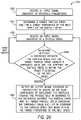
- FIG. 20is a flow diagram of an embodiment of a process for controlling a particle delivery system, in accordance with an aspect of the present disclosure
- FIG. 21is a cross-sectional view of an embodiment of a particle delivery system that may be employed within the row unit of FIG. 2 , in accordance with an aspect of the present disclosure
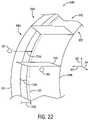
- FIG. 22is a perspective view of a portion of an embodiment of a particle delivery system, which may be employed within the row unit of FIG. 2 , having a particle belt and a particle belt housing, in accordance with an aspect of the present disclosure;
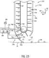
- FIG. 23is a cross-sectional view of a portion of an embodiment of a particle delivery system that may be employed within the row unit of FIG. 2 , in accordance with an aspect of the present disclosure
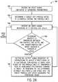
- FIG. 24is a flow diagram of an embodiment of a process for controlling a particle delivery system, in accordance with an aspect of the present disclosure
- FIG. 25is a cross-sectional view of an embodiment of a particle transfer section of a particle delivery system that may be employed within the row unit of FIG. 2 , in accordance with an aspect of the present disclosure
- FIG. 26is a cross-sectional view of an embodiment of a particle exit section of a particle delivery system that may be employed within the row unit of FIG. 2 , in accordance with an aspect of the present disclosure
- FIG. 27is a cross-sectional view of an embodiment of a particle delivery system that may be employed within the row unit of FIG. 2 , in accordance with an aspect of the present disclosure
- FIG. 28is a cross-sectional view of wheels and particle belts of the particle delivery system of FIG. 27 , in accordance with an aspect of the present disclosure
- FIG. 29is a front view of a particle belt of the particle delivery system of FIG. 27 , in accordance with an aspect of the present disclosure.
- FIG. 30is a cross-sectional view of an embodiment of a particle delivery system that may be employed within the row unit of FIG. 2 , in accordance with an aspect of the present disclosure.
- FIG. 31is a cross-sectional view of an inner particle belt and an outer particle belt of the particle delivery system of FIG. 30 , in accordance with an aspect of the present disclosure.
- Certain embodiments of the present disclosureinclude a particle delivery system for a row unit of an agricultural implement.
- Certain agricultural implementsinclude row units configured to deliver particles (e.g., seeds) to trenches in soil.
- a particle distribution systemmay transport the particles from a storage tank of the agricultural implement to the row units (e.g., to a hopper assembly of each row unit or directly to a particle delivery system of each row unit), and/or the particles may be delivered from a hopper assembly of each row unit to a respective particle delivery system.
- Each particle delivery systemmay output the particles to a respective trench as the agricultural implement travels over the soil.
- Certain agricultural implementsare configured to travel at particular speeds (e.g., between four kilometers per hour (kph) and thirty kph) while delivering the particles to the trenches. Additionally, a particular spacing between the particles when disposed within the soil may enhance plant development and/or yield.
- At least one row unit of the agricultural implementincludes a particle delivery system configured to deliver the particles to the respective trench in the soil at a particular spacing while reducing the relative ground speed of the particles (e.g., the speed of the particles relative to the ground).
- the particle delivery systemincludes a particle metering and singulation unit (e.g., including a metering wheel, a metering disc, etc.) configured to meter individual particles, thereby establishing the particular spacing between particles.
- the particle metering and singulation unitis configured to deliver the particles from a release point of the particle metering and singulation unit to a particle engagement section (e.g., to a particle engagement section of the particle engagement section) of a particle belt assembly, which includes a particle belt (e.g., an endless member).
- the particle beltincludes a base and flights coupled to the base. Each pair of opposing flights is configured to receive a respective particle from the particle metering and singulation unit. For example, each pair of opposing flights may receive the respective particle at a particle transfer section of the particle delivery system.
- the particle transfer sectionmay include the release point of the particle metering and singulation unit and/or the particle engagement section of the particle belt.
- the particle beltis configured to transport the particles from the particle transfer section toward a particle exit section of the particle belt assembly.
- the particle beltis configured to deliver and/or propel the particles into the trench in the soil.
- the particle beltmay accelerate the particles to a speed greater than a speed resulting from gravitational acceleration alone.
- the particle belt assemblymay enable the row unit to travel faster than traditional row units that utilize seed tubes, which rely on gravity to accelerate the particles (e.g., seeds) for delivery to soil.
- the particle metering and singulation unit and/or the particle belt assemblymay be controlled to achieve a desired ground speed and/or the particular spacings of the particles.
- the particle delivery systemmay include a controller configured to control a particle speed of particles moving between the particle metering and singulation unit and the particle belt (e.g., through/along the particle transfer section) and/or a particle exit speed of particles exiting the particle belt assembly.
- the controllermay be configured to control a distance between the particle metering and singulation unit and the particle belt, a force applied by a particle removal system to each particle at the particle metering and singulation unit, a rotational speed of a disc of the particle metering and singulation unit, an air flow configured to accelerate each particle from the particle metering and singulation unit toward the particle belt, or a combination thereof, to control the particle speed between the particle metering and singulation unit and the particle belt of the particle belt assembly.
- the controllermay be configured to control a protrusion configured to cause the flights of the particle belt to flex and/or pivot to accelerate the particles from the particle belt toward the trench in soil to control the particle exit speed from the particle belt assembly.
- FIG. 1is a perspective view of an embodiment of an agricultural implement 10 having multiple row units 12 distributed across a width of the agricultural implement 10 .
- the implement 10is configured to be towed through a field behind a work vehicle, such as a tractor.
- the implement 10includes a tongue assembly 14 , which includes a hitch configured to couple the implement 10 to an appropriate tractor hitch (e.g., via a ball, clevis, or other coupling).
- the tongue assembly 14is coupled to a tool bar 16 which supports multiple row units 12 .
- Each row unit 12may include one or more opener discs configured to form a particle path (e.g., trench) within soil of a field.
- the row unit 12may also include a particle delivery system (e.g., including a particle metering and singulation unit and a particle belt assembly) configured to deposit particles (e.g., seeds, fertilizer, and/or other agricultural product(s)) into the particle path/trench.
- the row unit 12may include closing disc(s) and/or a packer wheel positioned behind the particle delivery system. The closing disc(s) are configured to move displaced soil back into the particle path/trench, and the packer wheel is configured to pack soil on top of the deposited particles.
- the agricultural implement 10may travel at a particular speed along the soil surface while depositing the particles to the trenches.
- a speed of the agricultural implementmay be selected and/or controlled based on soil conditions, a type of the particles delivered by the agricultural implement 10 to the soil, a size (e.g., a nominal and/or an average size) of the particles, weather conditions, a size/type of the agricultural implement, or a combination thereof.
- a particular spacing between the particles when disposed within the soilmay enhance plant development and/or yield.
- At least one row unit 12may include a particle delivery system configured to deposit the particles at the particular spacing while reducing the ground speed of the particles (e.g., as compared to a row unit that employs a particle tube to delivery particles to the soil).
- the particle delivery systemmay include a particle metering and singulation unit configured to meter individual particles to a particle belt assembly to establish the spacing between the particles.
- the particle belt assemblymay include a particle belt configured to receive the particles from the particle metering and singulation unit and to accelerate the particles toward the trench in the soil. The particle belt may accelerate the particles to a speed greater than a speed resulting from gravitational acceleration alone.
- the particle belt assemblymay enable the row unit 12 to travel faster than traditional row units that utilize seed tubes, which rely on gravity to accelerate the particles (e.g., seeds) for delivery to soil.
- the agricultural implement 10may travel faster through the field and more accurately place each particle within the soil of the field.
- FIG. 2is a side view of an embodiment of a row unit 12 (e.g., agricultural row unit) that may be employed on the agricultural implement of FIG. 1 .
- the row unit 12includes a mount 18 configured to secure the row unit 12 to the tool bar of the agricultural implement.
- the mount 18includes a U-bolt that secures a bracket 20 of the row unit 12 to the tool bar.
- the mountmay include another suitable device that couples the row unit to the tool bar.
- a linkage assembly 22extends from the bracket 20 to a frame 24 of the row unit 12 .
- the linkage assembly 22is configured to enable vertical movement of the frame 24 relative to the tool bar in response to variations in a soil surface 26 .
- a down pressure system(e.g., including a hydraulic actuator, a pneumatic actuator, etc.) may be coupled to the linkage assembly 22 and configured to urge the frame 24 toward the soil surface 26 .
- a down pressure systeme.g., including a hydraulic actuator, a pneumatic actuator, etc.
- the illustrated linkage assembly 22is a parallel linkage assembly (e.g., a four-bar linkage assembly)
- another suitable linkage assemblymay extend between the bracket and the frame.
- the row unit 12includes an opener assembly 30 that forms a trench 31 in the soil surface 26 for particle deposition into the soil.
- the opener assembly 30includes gauge wheels 32 , arms 34 that pivotally couple the gauge wheels 32 to the frame 24 , and opener discs 36 .
- the opener discs 36are configured to excavate the trench 31 into the soil, and the gauge wheels 32 are configured to control a penetration depth of the opener discs 36 into the soil.
- the row unit 12includes a depth control system 38 configured to control the vertical position of the gauge wheels 32 (e.g., by blocking rotation of the arms in the upward direction beyond a selected orientation), thereby controlling the penetration depth of the opener discs 36 into the soil.
- the row unit 12includes a particle delivery system 40 configured to deposit particles (e.g., seeds, fertilizer, and/or other agricultural product(s)) into the trench 31 at a desired depth beneath the soil surface 26 as the row unit 12 traverses the field along a direction of travel 42 .
- the particle delivery system 40includes a particle metering and singulation unit 44 configured to receive the particles (e.g., seeds) from a hopper assembly 46 (e.g., a particle storage area).
- the hopper assemblymay be integrally formed with a housing of the particle metering and singulation unit.
- the hopper assembly 46is configured to store the particles for subsequent metering by the particle metering and singulation unit 44 and delivery to the soil by a particle belt assembly of the particle delivery system 40 .
- the particle metering and singulation unit 44includes a disc configured to rotate to transfer the particles from the hopper assembly 46 toward a particle belt of the particle belt assembly.
- the particle belt assemblymay generally extend from the particle metering and singulation unit 44 toward the trench 31 formed in the soil and may transfer the particles received from the particle metering and singulation unit 44 to the trench 31 .
- the opener assembly 30 and the particle delivery system 40are followed by a closing assembly 48 that moves displaced soil back into the trench 31 .
- the closing assembly 48includes two closing discs 50 .
- the closing assemblymay include other closing devices (e.g., a single closing disc, etc.).
- the closing assemblymay be omitted.
- the closing assembly 48is followed by a packing assembly 52 configured to pack soil on top of the deposited particles.
- the packing assembly 52includes a packer wheel 54 , an arm 56 that pivotally couples the packer wheel 54 to the frame 24 , and a biasing member 58 configured to urge the packer wheel 54 toward the soil surface 26 , thereby enabling the packer wheel to pack soil on top of the deposited particles (e.g., seeds and/or other agricultural product(s)).
- the illustrated biasing member 58includes a spring
- the biasing membermay include another suitable biasing device, such as a hydraulic cylinder or a pneumatic cylinder, among others.
- the direction of travel 42 of the row unit 12may be generally along the longitudinal axis 60 .
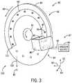
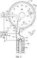
- FIG. 3is a perspective view of an embodiment of the particle metering and singulation unit 44 and a particle hopper 80 of the particle delivery system 40 that may be employed within the row unit of FIG. 2 .
- the particle hopper 80is a particle storage area configured to store particles 82 (e.g., seeds, fertilizer, other particulate material, or a combination thereof) for subsequent metering by the particle metering and singulation unit 44 .
- the particle hopper 80may be coupled to and/or included as part of a housing of the particle metering and singulation unit 44 .
- the hopper assemblymay feed the particles 82 into and/or may be coupled to the particle hopper 80 .
- the particle metering and singulation unit 44includes a disc 84 having apertures 86 configured to receive the particles 82 from the particle hopper 80 .
- each aperture 86may receive a single particle 82 .
- the particle metering and singulation unit 44includes an air flow system 87 having a vacuum source 88 (e.g., a fan) configured to generate an air flow through the apertures 86 (e.g., generally along the lateral axis 64 ) at a particle reception section 89 adjacent to the particle hopper 80 .
- the air flowis configured to form a vacuum (e.g., a vacuum pressure) at the apertures 86 , thereby drawing the particles 82 from the particle hopper 80 toward and into the apertures 86 .
- a vacuume.g., a vacuum pressure
- an air tube 90 of the air flow system 87extends generally from the vacuum source 88 to the disc 84 .
- the vacuum source 88is configured to generate the air flow from the particle hopper 80 , through the apertures 86 and the air tube 90 , and toward the vacuum source 88 .
- the particle metering and singulation unit 44also includes a vacuum passage 99 extending generally from the particle hopper 80 to a particle transfer section 100 of the particle delivery system 40 , where the particles 82 are transferred from the particle metering and singulation unit 44 to the particle belt.
- the vacuum source 88is configured to form the vacuum at the apertures 86 generally at a first end of the vacuum passage 99 generally adjacent to the particle hopper 80 .
- the particle metering and singulation unit 44is configured to transfer the particles 82 generally at a second end of the vacuum passage 99 by removing and/or occluding the vacuum at the apertures 86 .
- the vacuumis applied at the particle metering and singulation unit 44 only at/along the vacuum passage 99 .
- the apertures of the discmay be configured to receive the particles via other suitable methods.
- the discmay include a scoop at each aperture configured to scoop a respective particle from the particle hopper as the aperture rotates by the particle hopper in the particle reception section.
- the particle delivery systemmay include other systems configured to form a pressure differential at the apertures of the disc, such as an air source configured to push the particles into/against the disc and into the apertures of the disc.
- the particle hopper 80 and the particle reception section 89are generally opposite of the particle transfer section 100 along the disc 84 .
- the particle hopper and/or the particle reception sectionmay be substantially closer and/or adjacent to the particle transfer section of the particle delivery system.
- vacuumrefers to an air pressure that is less than the ambient atmospheric air pressure, and not necessarily 0 pa.
- the particle metering and singulation unit 44includes a gear 92 coupled to the disc 84 and configured to drive the disc 84 to rotate in a rotational direction 94 (e.g., generally about the lateral axis 64 ).
- a rotational direction 94e.g., generally about the lateral axis 64
- the apertures 86collect respective particles 82 from the particle hopper 80 and move the particles 82 from the particle reception section 89 to the particle transfer section 100 .
- the gear 92may drive rotation of the disc 84 , such that a tangential speed of the particles 82 exiting the disc 84 is generally between one tenth kph to twenty kph.
- the particles 82are released from the particle metering and singulation unit 44 at a release point 101 of the particle metering and singulation unit 44 toward the particle belt of the particle belt assembly along a flow path 102 (e.g., a release trajectory).
- a flow path 102e.g., a release trajectory
- the vacuum passage 99extends generally between the particle hopper 80 and the release point 101 .
- the particle transfer section 100may include the particle metering and singulation unit 44 , portion(s) of the particle metering and singulation unit 44 (e.g., the release point 101 ), a particle tube extending between the particle metering and singulation unit 44 and the particle belt, portion(s) of the particle tube, the particle belt, portion(s) of the particle belt (e.g., a particle engagement section of the particle belt where the particle belt is configured to receive the particles 82 ), or a combination thereof.
- the particle delivery systemmay include systems and/or methods configured to remove the particles 82 from the apertures 86 of the particle metering and singulation unit 44 at the particle transfer section 100 .
- the disc 84 having the apertures 86may be any suitable shape configured to rotate/move to transfer the particles 82 from the particle hopper 80 to the release point 101 .
- the disc 84may be generally flat, may have a curved portion and a flat portion, may be entirely curved, may be a drum, or may include other suitable shapes, geometries, and/or configurations.
- an inner portion of the disc 84may curved/raised related to an outer portion of the disc 84 having the apertures 86 (e.g., the disc 84 may be generally bowl-shaped), such that the particles 82 may be directed toward the apertures 86 (e.g., away from the raised inner portion and/or toward the flat outer portion) as the disc 84 rotates.
- the disc 84may be a drum having the apertures 86 disposed along an outer portion and/or an exterior of the drum.
- FIG. 4is a cross-sectional view of the particle delivery system 40 that may be employed within the row unit of FIG. 2 .
- the particle metering and singulation unit 44is configured to transfer the particles 82 from the particle reception section 89 toward the particle transfer section 100 .
- the particles 82are transferred from the particle metering and singulation unit 44 (e.g., from a release point 101 of the particle metering and singulation unit 44 ) toward a particle belt assembly 120 of the particle delivery system 40 along the flow path 102 .
- the particle metering and singulation unit 44via the air flow system, is configured to maintain the vacuum within each aperture 86 along the vacuum passage 99 (e.g., from the particle reception section 89 to the particle transfer section 100 ). At the particle transfer section 100 , the vacuum within each aperture 86 is removed and/or occluded, such that the particle 82 within the aperture 86 may fall downwardly along the flow path 102 under the influence of gravity.
- a vacuum removal system 121 of the particle delivery system 40 disposed at an end of the vacuum passage 99 adjacent to the particle transfer section 100is configured to remove the vacuum at each aperture 86 as each aperture 86 passes by the vacuum removal system 121 at the release point 101 (e.g., remove the vacuum established by the air flow generated by the vacuum source at the particle reception section 89 ).
- the vacuum removal system 121may remove the vacuum at each aperture 86 by providing a positive air flow toward the particle 82 and/or by end the vacuum passage 99 (e.g., by introducing a positive air pressure configured to overcome the vacuum at the aperture 86 ).
- the particle delivery systemmay include other systems configured to remove the particles from the particle metering and singulation unit at the particle transfer section.
- the particle metering and singulation unit 44includes a particle metering and singulation unit housing 122 configured to house the disc 84 .
- the particle delivery system 40includes a particle tube 124 having a first end 126 at the particle metering and singulation unit 44 (e.g., coupled to the particle metering and singulation unit housing 122 and disposed adjacent to the release point 101 of the particle metering and singulation unit 44 ) and a second end 128 at the particle belt assembly 120 (e.g., coupled to the particle belt assembly 120 ).
- the particles 82are configured to flow from the particle metering and singulation unit 44 , through the particle tube 124 , and toward the particle belt assembly 120 .
- the particle tubemay include any suitable shape and/or configuration configured to at least particle direct the particles, such as a channel, a cylindrical tube, a rectangular tube, and/or other suitable shapes/configurations.
- the particle belt assembly 120is configured to transfer the particles 82 from the particle transfer section 100 toward a particle exit section 130 of the particle delivery system 40 and toward the trench 31 .
- the particle belt assembly 120includes a particle belt housing 132 , a particle belt 134 (e.g., an endless member) disposed within the particle belt housing 132 , and wheels 136 (e.g., gears, pulleys, etc.) configured to drive/enable the particle belt 134 to turn/rotate, as indicated by arrows 138 .
- the particle belt housing 132is coupled to the second end 128 of the particle tube 124 .
- the particle belt 134includes a base 140 and flights 142 coupled to the base 140 .
- Each pair of opposing flights 142 along the particle belt 134is configured to receive and/or capture a respective particle 82 from the particle metering and singulation unit 44 at a particle engagement section 143 of the particle belt 134 and of the particle transfer section 100 .
- the flights 142are generally disposed at a right angle relative to the base 140 .
- at least one flightmay be oriented at another suitable angle relative to the base (e.g., at an acute angle between the flight and the base).
- the second end 128 of the particle tube 124is disposed adjacent to the particle engagement section 143 of the particle belt 134 .
- the particle tube 124extends generally from the release point 101 of the particle metering and singulation unit 44 to the particle engagement section 143 of the particle belt 134 .
- the particle metering and singulation unit 44is configured to meter the particles 82 to provide a spacing between the particles 82 .
- the particle metering and singulation unit 44is configured to release each particle 82 , which may travel through the particle tube 124 and toward the particle belt 134 .
- the particle belt 134is configured to receive each particle 82 at the particle engagement section 143 and to move the particle 82 toward the particle exit section 130 and toward the trench 31 .
- the disc 84 of the particle metering and singulation unit 44 and the particle belt 134may move (e.g., rotate) at different speeds.
- the particle belt 134may move generally faster than the disc 84 (e.g., the particle belt 134 may rotate faster than the disc 84 and/or a tangential speed of the particle belt 134 may be greater than a tangential speed of the disc 84 at the apertures 86 ), such that the particle belt 134 may accelerate the particles 82 received from the disc 84 toward the trench 31 .
- the particle belt 134may accelerate the particles 82 to a speed greater than a speed resulting from gravitational acceleration alone.
- the particle belt assembly 120may enable the row unit to travel faster than traditional row units that utilize seed tubes, which rely on gravity to accelerate the particles 82 (e.g., seeds) for delivery to soil.
- the particle metering and singulation unit 44 and the particle belt 134are separated by a distance 150 (e.g., a selected distance).
- the distance 150extends from the release point 101 of the particle metering and singulation unit 44 and of the particle transfer section 100 to the particle engagement section 143 of the particle belt 134 and of the particle transfer section 100 .
- the distance 150is a vertical distance that enables the particles 82 to accelerate under the influence of gravity from the particle metering and singulation unit 44 to the particle belt 134 .
- the distance 150may be any suitable distance configured to sufficiently accelerate the particles 82 , such that the particle speed of the particles entering the particle belt 134 (e.g., at the particle engagement section 143 ) is closer to the belt speed of the particle belt 134 .
- the acceleration of the particles 82 along the particle transfer section 100e.g., from the release point 101 to the particle engagement section 143
- the distance 150may be between two one centimeter (cm) and one meter (m), between ten cm and fifty cm, between twenty cm and thirty cm, and other suitable distances.
- the distance 150may be selected to bring the particle speed of the particles 82 at the particle engagement section 143 to within a target percentage of the belt speed.
- the particle belt assembly 120includes a track 162 , and the wheels 136 (e.g., gears, pulleys, etc.) are movably coupled to the track 162 .
- the particle belt assembly 120is configured to move generally vertically (e.g., along the vertical axis 62 ) via movement of the wheels 136 along the track 162 and within the particle belt housing 132 .
- an actuator 164 of the particle delivery system 40is configured to drive the wheels 136 along the track 162 . To increase the distance 150 , the actuator 164 may move the particle belt 134 downwardly along the track 162 . To decrease the distance 150 , the actuator 164 may move the particle belt 134 upwardly along the track 162 .
- the particle belt housingmay be coupled to the track and configured to move generally vertically along the track to adjust the distance between the release point and the particle engagement section.
- the particle tubemay be flexible and/or may telescope, such that the particle tube may remain coupled to the particle metering and singulation unit housing and the particle belt housing as the particle belt housing moves generally vertically relative the particle metering and singulation unit housing.
- the particle delivery systemmay include a track or other mechanism configured to enable the particle metering and singulation unit to move generally vertically with respect to the particle belt assembly.
- only a single wheel coupled to the trackmay be configured to move along the track (e.g., the wheel closer to the particle metering and singulation unit), such that the particle belt may stretch/retract as the single wheel moves along the track.
- a controller 170 of the particle delivery system 40may control the distance 150 between the particle metering and singulation unit 44 and the particle belt 134 to control the speed at which each particle 82 engages the particle belt 134 (e.g., the distance 150 may be a selected/controlled distance).
- the controller 170may control the distance 150 (e.g., control movement of the particle belt assembly 120 with respect to the particle metering and singulation unit 44 ) to control the particle speed of each particle 82 at the particle engagement section 143 of the particle belt 134 (e.g., such that the particle speed at the particle belt 134 is within a target percentage of a belt speed of the particle belt 134 ).
- the target percentagemay be determined by the controller 170 based on a type of the particles 82 , a size of each particle 82 of the particles 82 (e.g., a nominal and/or an average size), a ground speed of the row unit, a spacing between the flights 142 of the particle belt 134 , a length of the particle belt 134 , the belt speed of the particle belt 134 , or a combination thereof.
- a size of each particle 82 of the particles 82e.g., a nominal and/or an average size
- a ground speed of the row unite.g., a spacing between the flights 142 of the particle belt 134 , a length of the particle belt 134 , the belt speed of the particle belt 134 , or a combination thereof.
- the target percentagemay be any suitable percentage, such as ten percent, twenty percent, thirty percent, forty percent, fifty percent, sixty percent, seventy percent, eighty percent, ninety percent, between ten percent and one hundred percent, between fifty and one hundred percent, between fifty and ninety percent, between sixty percent and eighty percent, between seventy percent and eighty percent, etc.
- the controller 170may receive an input signal indicative of the particle speed of the particle 82 at the particle engagement section 143 of the particle belt 134 .
- the controller 170may receive the input signal from a particle sensor 172 of the particle delivery system 40 disposed within the particle tube 124 adjacent to the particle belt 134 .
- the particle sensor 172may include an infrared sensor or another suitable type of sensor configured to output the input signal indicative of the particle speed of each particle 82 at the particle belt 134 .
- the particle sensor 172may remain a fixed distance from the particle engagement section 143 of the particle belt 134 , such that the controller 170 may determine the particle speed of the particle 82 at the particle engagement section 143 based on the fixed distance and the input signal indicative of the particle speed received from the particle sensor 172 (e.g., based on gravitational acceleration of the particle 82 traveling the fixed distance from the particle sensor 172 to the particle engagement section 143 of the particle belt 134 ).
- the controller 170may also receive an input signal indicative of the belt speed of the particle belt 134 and/or may determine the belt speed of the particle belt 134 .
- the controller 170may control the belt speed of the particle belt 134 (e.g., output an output signal indicative of instructions to adjust the belt speed of the particle belt 134 to a target belt speed) based on the type of the particles 82 , the size of the particles 82 , the ground speed of the row unit, the spacing between the flights 142 of the particle belt 134 , a length of the particle belt 134 , or a combination thereof.
- the particle delivery systemmay include a belt sensor configured to output a signal indicative of the belt speed of the particle belt.
- the controller 170may determine other information related to the particles 82 based on feedback from the sensor 172 , such as skips of the particles 82 (e.g., the particle 82 not being present during an expected time period), multiple particles 82 (e.g., multiple particles 82 being present when only a single particle 82 is expected), an amount of particles 82 deposited over a given area (e.g., an amount of particles 82 deposited per acre), and other information related to the particles 82 . In some embodiments, the controller 170 may control the particle delivery system based on such determinations.
- the controller 170may compare the particle speed of the particle 82 at the particle belt 134 to the belt speed of the particle belt 134 to determine whether the particle speed is within the target percentage of the belt speed. In response to a determination that the particle speed at the particle belt 134 is less than the belt speed and is not within the target percentage of the belt speed, the controller 170 may output an output signal indicative of instructions to increase the distance 150 between the particle metering and singulation unit 44 and the particle belt 134 . For example, the controller 170 may output the output signal to the actuator 164 to cause the actuator 164 to move the particle belt 134 downwardly to increase the distance 150 . The increase in the distance 150 may increase the particle speed of the particle 82 at the particle belt 134 , such that the particle speed may be within the target percentage of the belt speed of the particle belt 134 .
- the controller 170may output an output signal indicative of instructions to decrease the distance 150 between the particle metering and singulation unit 44 and the particle belt 134 .
- the controller 170may output the output signal to the actuator 164 to cause the actuator to move the particle belt 134 upwardly to decrease the distance 150 .
- the decrease in the distance 150may decrease the particle speed of the particle 82 at the particle belt 134 , such that the particle speed may be within the target percentage of the belt speed of the particle belt 134 .
- the controller 170 of the particle delivery system 40includes a processor 180 and a memory 182 .
- the processor 180e.g., a microprocessor
- the processor 180may be used to execute software, such as software stored in the memory 182 for controlling the particle delivery system 40 (e.g., for controlling position(s) of the particle metering and singulation unit and/or the particle belt).
- the processor 180may include multiple microprocessors, one or more “general-purpose” microprocessors, one or more special-purpose microprocessors, and/or one or more application specific integrated circuits (ASICS), or some combination thereof.
- ASICSapplication specific integrated circuits
- the processor 180may include one or more reduced instruction set (RISC) or complex instruction set (CISC) processors.
- RISCreduced instruction set
- CISCcomplex instruction set
- the memory device 182may include a volatile memory, such as random access memory (RAM), and/or a nonvolatile memory, such as read-only memory (ROM).
- RAMrandom access memory
- ROMread-only memory
- the memory device 182may store a variety of information and may be used for various purposes.
- the memory device 182may store processor-executable instructions (e.g., firmware or software) for the processor 180 to execute, such as instructions for controlling the particle delivery system 40 .
- the controller 170may also include one or more storage devices and/or other suitable components.
- the storage device(s)e.g., nonvolatile storage
- the storage device(s)may store data (e.g., the target percentage of the belt speed), instructions (e.g., software or firmware for controlling the particle delivery system 40 ), and any other suitable data.
- the processor 180 and/or the memory device 182 , and/or an additional processor and/or memory device,may be located in any suitable portion of the system.
- a memory device for storing instructionse.g., software or firmware for controlling portions of the particle delivery system 40
- the particle delivery system 40includes a user interface 184 that is communicatively coupled to the controller 170 .
- the user interface 184may be configured to inform an operator of the particle speed of the particles 82 , to inform the operator of information related to the particles 82 and determined by the controller 170 (e.g., the skips of the particles 82 , multiple particles 82 , etc.), to enable the operator to adjust the belt speed of the particle belt 134 , to provide the operator with selectable options of the type of particles 82 , to enable the operator to set minimum and maximum values of the distance 150 , and to enable other operator interactions.
- the user interface 184may include a display and/or other user interaction devices (e.g., buttons) configured to enable operator interactions.
- the distance 150 between the release point 101 and the particle engagement section 143may be fixed.
- the particle tube 124 , the actuator 164 , the controller 170 , the sensor 172 , the user interface 184 , other portion(s) of the particle delivery system 40 , or a combination thereofmay be omitted from the particle delivery system 40 .
- FIG. 5is a flow diagram of an embodiment of a process 190 for controlling the particle delivery system.
- the process 190may be performed by the controller of the particle delivery system.
- the process 190begins at block 192 , in which an input signal indicative of operating parameter(s) is received.
- the operating parametersmay include the type of the particles, the size of the particles, the ground speed of the row unit, the spacing between opposing flights of the particle belt, the length of the particle belt, the belt speed of the particle belt, or a combination thereof.
- the input signalmay be received via the user interface communicatively coupled to the controller, may be stored in the memory of the controller, may be received via sensor(s) of the row unit and/or the agricultural implement, may be received from a transceiver, or a combination thereof.
- the target percentage of the belt speed of the particle beltis determined.
- the controllermay determine the target percentage of the belt speed based on the type of the particles, the size of the particles, the ground speed of the row unit, the spacing between opposing flights of the particle belt, the length of the particle belt, or a combination thereof.
- an input signal indicative of the particle speed of each particle at the particle engagement section of the particle beltis received.
- the controllermay receive the input signal indicative of the particle speed from the particle sensor disposed generally between the particle metering and singulation unit and the particle belt and generally along the flow path.
- the controllermay receive multiple input signals from the particle sensor, in which each input signal is indicative of a particle speed of a respective particle.
- the controllermay determine an average of the multiple particle speeds to determine the average particle speed of the particles at the particle belt.
- the controllermay account for variance among the particle speeds of multiple particles passing along the flow path to reduce excessive control actions (e.g., adjustments to the distance between the particle metering and singulation unit and the particle belt).
- a determination of whether the particle speed is within the target percentage of the belt speedis made (e.g., by the controller). For example, the controller may compare the particle speed of the particle at the particle belt to the belt speed to determine whether the particle speed is within the target percentage of the belt speed. Additionally or alternatively, the controller may determine whether the particle speed is less than or greater than the belt speed.
- the process 190proceeds to block 200 .
- the process 190returns to block 196 and receives the next input signal indicative of the particle speed.
- an output signal indicative of instructions to adjust the distance between the particle metering and singulation unit and the particle beltis output to the actuator to move the particle belt and/or the particle metering and singulation unit to adjust the distance between the particle belt and the particle metering and singulation unit.
- the distance between the particle belt and the particle metering and singulation unitis a selected distance (e.g., a distance selected and/or adjusted by the controller).
- the controllermay output an output signal indicative of instructions to increase the distance based on a determination that the particle speed at the particle belt is less than the belt speed and is not within the target percentage of the belt speed.
- the controllermay output an output signal indicative of instructions to decrease the distance based on a determination that the particle speed at the particle belt is greater than the belt speed and is not within the target percentage of the belt speed.
- blocks 196 - 200 of the process 190may be iteratively performed (e.g., by the controller of the particle delivery system and/or by another suitable controller) to facilitate transfer of the particles from the particle metering and singulation unit to the particle belt.
- certain blocks of the blocks 192 - 200may be omitted from the process 190 and/or the order of the blocks 192 - 200 may be different.
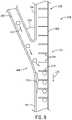
- FIG. 6is a perspective view of a portion of an embodiment of a particle belt 210 of a particle delivery system that may be employed within the row unit of FIG. 2 .
- the particle belt 210includes a base 212 and flights 214 coupled to the base 212 .
- Each flight 214is disposed at an angle 216 relative to the base 212 , thereby forming the illustrated angled flights 214 .
- the angle 216may be between fifteen degrees and eighty-five degrees, between thirty degrees and seventy-five degrees, between forty degrees and sixty degrees, between forty-five degrees and eighty degrees, between sixty and eighty degrees, about fifty degrees, or other suitable angles.
- the angle 216may be the same for each flight 214 or may different for some flights 214 .
- the angle 216 of the flights 214 relative to the base 212may facilitate transfer of the particles 82 from the particle metering and singulation unit to a particle engagement section 217 of the particle belt 210 (e.g., between opposing flights 214 of the particle belt 210 ).
- the flights 214 disposed at the angle 216may be generally parallel to and/or oriented along a flow path 218 of the particles 82 from the particle metering and singulation unit to the particle belt 210 .
- the flights 214 disposed at the angle 216may facilitate particle transfer at the particle transfer section of the particle delivery system (e.g., facilitate transfer to the particle engagement section 217 of the particle belt 210 ).
- FIG. 7is a perspective view of an embodiment of a particle metering and singulation unit 220 and a particle tube 222 of a particle delivery system that may be employed within the row unit of FIG. 2 .
- the particle metering and singulation unit 220includes a disc 224 having apertures 226 formed along a side 228 (e.g., a lateral side location) of the disc 224 and configured to carry and transport the particles 82 toward the particle tube 222 .
- the particle tube 222includes an end 230 disposed adjacent to the side 228 of the disc 224 .
- the end 230 of the particle tube 222is disposed a distance 231 apart from the side 228 of the disc 224 .
- the distance 231may be about one tenth of a millimeter (mm), one mm, about two mm, about five mm, or another suitable distance.
- the side 228 of the disc 224is generally flat.
- the cross-sectional shape of the particle tube 222e.g., the cross-sectional shape within a plane perpendicular to the longitudinal axis of the particle tube 222 , at least at the end 230 , has a flat portion 232 and a curved portion 234 , thereby forming a “D-shaped” end 230 .
- the flat portion 232extends generally parallel to the side 228 of the disc 224 and is configured to be aligned with the side 228 , as illustrated.
- the flat portion 232 of the particle tube 222is disposed the distance 231 apart from the side 228 of the disc 224 generally at the apertures 86 .
- the distance 231e.g., the relatively small/narrow distance
- the flat portion 232may contact the particles 82 and/or the side 228 to dislodge and removes the particles 82 from the apertures 226 of the disc 224 (e.g., from a release point 237 of the particle metering and singulation unit 220 ).
- the flat portion of the particle tubemay be disposed on an opposite side of the disc relative to the curved portion of the particle tube, such that the disc extends into/through a slot of the particle tube (e.g., a slot formed between the flat portion and the curved portion of the particle tube). Additionally or alternatively, the flat portion of the particle tube may be omitted.
- the movement of the disc 224 in the rotational direction 236may propel the particles 82 into the particle tube 222 .
- a devicemay be attached to the end of the particle tube adjacent to the disc that is configured to remove (e.g. knock, scrape, etc.) the particles from the disc, such as a paddle, a hook, or a brush.
- the curved portion 234 of the particle tube 222may direct the particles 82 downwardly toward the particle belt of the particle delivery system.
- the flat portion 232 of the particle tube 222extends a width 238 adjacent to the disc 224 .
- the width 238may be about one half cm, one cm, two cm, four cm, or other suitable widths.
- the width 238 of the particle tube 222 along the flat portion 232may be less than the illustrated embodiment.
- the widthmay be slightly greater than the maximum expected extent (e.g., maximum expected diameter) of the particles flowing from the disc. As a result, movement of the particles from the particle metering and singulation unit toward the particle belt may be facilitated by reducing tumbling of the particles within the particle tube.
- a cross-sectional shape of the particle tubemay be different at certain longitudinal portions of the particle tube.
- the particle tubemay have the D-shaped cross-section.
- the cross-sectional shapemay change to be square or circular, for example.
- a size of the cross-section of the particle tubee.g., the cross-sectional area of the particle tube within a plane perpendicular to the longitudinal axis of the particle tube
- the particle tubemay have a first cross-sectional area.
- the cross-sectional areamay decrease such that the cross-sectional area at a second end of the particle tube adjacent to the particle belt is less than the cross-sectional area at the first end.
- the narrowing of the cross-section of the particle tubemay direct the particles flowing from the particle metering and singulation unit toward a particular portion of the particle belt.
- the cross-sectional area at the second end of the particle tubemay be about ninety percent, eight percent, seventy percent, sixty percent, fifty percent, twenty-five percent, ten percent, or other suitable percentages of the cross-sectional area at the first end of the particle tube.
- FIG. 8is a cross-sectional view of a portion of an embodiment of a particle delivery system 258 , which may be employed within the row unit of FIG. 2 , having a particle tube 260 and a particle belt assembly 262 .
- the particle belt assembly 262includes a particle belt housing 264 and a particle belt 266 disposed within the particle belt housing 264 .
- the particle tube 260is coupled to the particle belt housing 264 at a second end 268 of the particle tube 260 .
- the particle tube 260is disposed at an angle 270 relative to the particle belt housing 264 .
- a flow path 272 of the particles 82 traveling through the particle tube 260extends at the angle 270 relative to a travel path 274 of the particle belt 266 , such that the particles 82 may flow toward the particle belt 266 at the angle 270 .
- the angle 270may be an acute angle configured to facilitate transfer of the particles 82 from the particle tube 260 to the particle belt 266 .
- the angle 270may be between five degrees and eighty-five degrees, between fifteen degrees and seventy degrees, between twenty-five degrees and sixty degrees, about thirty degrees, about forty degrees, or other suitable angles.
- the particle delivery system 258is configured to flow the particles 82 to a side portion 275 of the particle belt 266 (e.g., to a particle engagement section 276 of the particle belt 266 where the particle belt 266 is traveling along a generally straight path), rather than an end portion of the particle belt 266 where the particle belt 266 is traveling along a curved path around a wheel/pulley.
- Delivering the particles 82 to the side portion 275 of the particle belt 266may facilitate receipt of the particles 82 by flights 278 of the particle belt 266 , because the flow path 272 of the particles 82 may be in a generally similar direction as the travel path 274 of the flights 278 (e.g., the flow path 272 of the particles 82 directionally differs from the travel path 274 of the particle belt 266 only by the angle 270 ).
- the particle delivery system 258includes a particle indexing unit 279 coupled to the particle belt housing 264 adjacent or proximate to the second end 268 of the particle tube 260 .
- the particle indexing unit 279is configured to facilitate particle transfer/indexing from the particle tube 260 to the particle belt 266 .
- the particle indexing unit 279may guide each particle 82 between respective opposing flights 278 of the particle belt 266 as the particle 82 flows through the second end 268 of the particle tube 260 into the particle belt housing 264 .
- the particle indexing unitmay extend into and/or may be coupled to the particle tube.
- the particle indexing unit 279is a rumble strip (e.g., a strip formed of rubber, plastic, and/or other materials having ridges) configured to cause the particles 82 to roll and/or to alter the direction of the particles 82 to cause the particles 82 to move between opposing flights 278 of the particle belt 266 .
- the particle indexing unitmay include other features configured to alter the direction of the particles to cause the particles to move between the opposing flights.
- the particle indexing unitmay be omitted.
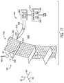
- FIG. 9is a cross-sectional view of an embodiment of a particle delivery system 300 that may be employed within the row unit of FIG. 2 .
- the particle delivery system 300includes a particle metering and singulation unit 302 , a particle tube 304 , and a particle belt assembly 306 coupled to the particle metering and singulation unit 302 via the particle tube 304 .
- the particle metering and singulation unit 302is configured to meter and transfer the particles 82 from a particle storage area 310 and toward a particle transfer section 312 .
- the particle delivery system 300is configured to transfer the particles 82 from the particle metering and singulation unit 302 (e.g., from a release point 313 of the particle metering and singulation unit 302 and of the particle transfer section 312 ) to the particle belt assembly 306 .
- the particle metering and singulation unit 302includes a gear 314 and a disc 316 coupled to the gear 314 .
- the gear 314is configured to drive the disc 316 to rotate in a rotational direction 318 .
- the disc 316includes a side surface 319 having apertures 320 formed along a periphery 321 of the disc 316 and configured to carry and transport the particles 82 .
- the apertures 320are configured to collect respective particles 82 from the particle storage area 310 and to move the particles 82 from the particle storage area 310 toward a side location 322 (e.g., a lateral side location) of the side surface 319 of the disc 316 .
- the particle delivery system 300is configured to release the particles 82 along a release trajectory 324 .
- a particle removal system 326 of the particle delivery system 300may release the particles 82 from the apertures 320 by removing a vacuum pressure configured to secure the particles 82 within the apertures 320 .
- the particle removal systemmay include other systems/means configured to remove and/or release the particles from the apertures. After releasing the particles 82 from the apertures 320 , the particles 82 are configured to flow along the release trajectory 324 from the disc 316 toward a particle belt 330 of the particle belt assembly 306 .
- Flights 332 of the particle belt 330are configured to receive the particles 82 from the particle metering and singulation unit 302 at a particle engagement section 333 of the particle belt 330 and of the particle transfer section 312 .
- the flights 332are disposed at an angle 334 relative to the release trajectory 324 and are coupled to a base 341 of the particle belt 330 .
- the angle 334may be an acute angle generally between five and forty-five degrees, about fifteen degrees, about twenty-five degrees, about thirty-five degrees, or other suitable angles.
- the flights of the particle beltmay extend generally along the release trajectory such that the particles may flow to the particle belt between opposing flights and along the flights.
- the particle belt 330is configured to rotate along a travel path 335 , via wheels 336 of the particle belt assembly 306 , to deliver the particles 82 to the trench 31 .
- the travel path 335is a linear direction of movement of the base 341 at the particle engagement section 333 of the particle belt 330 .
- the particle belt 330may rotate generally faster than the rotational speed of the disc 316 , such that the particle belt 330 may accelerate the particles 82 received from the disc 316 toward the trench 31 .
- the particle metering and singulation unit 302is configured to release the particles 82 at the side location 322 such that a tangential speed of the disc 316 at the side location 322 is imparted to each particle 82 , thereby causing the particle 82 to move downwardly in a direction toward the particle belt 330 .
- the release trajectory 324may extend generally along the vertical axis 62 and/or within a selected angle of the vertical axis 62 , which may cause the particles 82 to accelerate under the influence of gravity toward the particle belt 330 . Accordingly, as the particle 82 reaches the particle belt 330 , the speed of the particle 82 may be substantially equal to the sum of the tangential speed of the disc 316 at the side location 322 and the speed caused by gravitational acceleration between the release point 313 and the particle engagement section 333 . As the particle 82 accelerates downwardly toward the particle belt 330 , the particle speed of the particle 82 increases and a difference between the particle speed and the belt speed of the particle belt 330 decreases.
- the decrease in the speed differencemay facilitate receipt of the particles 82 at the particle engagement section 333 of the particle belt 330 , because the flights 332 and the particles 82 may be moving at generally similar speeds.
- the release trajectory 324may be within forty-five degrees of the vertical axis 62 , within thirty-five degrees of the vertical axis 62 , within twenty-five degrees of the vertical axis 62 , within fifteen degrees of the vertical axis 62 , within five degrees of the vertical axis 62 , within one degree of the vertical axis 62 , or within another suitable angle of the vertical axis 62 .
- the controller 170 of the particle delivery system 300is configured control the speed of the particles 82 by adjusting the rotational speed of the disc 316 of the particle metering and singulation unit 302 .
- the controller 170may control a motor 337 coupled to and configured to drive rotation of the gear 314 to control the rotational speed of the disc 316 , thereby controlling the exit speed of each particle 82 from the disc 316 along the release trajectory 324 .
- the controller 170may control the rotational speed of the disc 316 such that a particle speed of each particle 82 at the particle belt 330 (e.g., the speed substantially corresponding to the sum of the tangential speed of the disc 316 at the side location 322 and the speed of the particle 82 caused by gravitational acceleration) reaches a target particle speed and/or is within a target percentage of a belt speed of the particle belt 330 .
- a particle speed of each particle 82 at the particle belt 330e.g., the speed substantially corresponding to the sum of the tangential speed of the disc 316 at the side location 322 and the speed of the particle 82 caused by gravitational acceleration
- the target particle speed and/or target percentagemay be determined by the controller 170 based on a type of the particles 82 , a size (e.g., a nominal and/or an average size) of the particles 82 , a ground speed of the row unit, a spacing between flights of the particle belt 330 , a length of the particle belt 330 , the belt speed of the particle belt 330 , or a combination thereof.
- a sizee.g., a nominal and/or an average size
- the target particle speedmay be any suitable particle speed, such as one kph, two kph, three kph, four kph, five kph, seven kph, ten kph, fifteen kph, twenty kph, between one kph and twenty kph, between five kph and fifteen kph, etc.
- the controller 170may receive an input signal indicative of the particle speed of the particle 82 at the particle engagement section 333 of the particle belt 330 .
- the controller 170may receive the input signal from a particle sensor 172 of the particle delivery system 300 disposed within the particle tube 304 adjacent to the particle belt 330 .
- the controller 170may also receive an input signal indicative of the belt speed of the particle belt 330 , and/or the controller 170 may determine the belt speed of the particle belt 330 .
- the particle delivery systemmay include a belt sensor configured to output the input signal indicative of the belt speed of the particle belt.
- the controller 170may set the belt speed of the particle belt 330 (e.g., output an output signal indicative of instructions to adjust the belt speed of the particle belt 330 to a target belt speed) based on the type of particles 82 , the ground speed of the row unit, the spacing between the flights of the particle belt 330 , a length of the particle belt 330 , or a combination thereof.
- the controller 170may determine the target particle speed at least partially based on the set belt speed of the particle belt 330 and/or based on feedback from the belt sensor.
- the controller 170may compare the particle speed of the particles 82 at the particle belt 330 to the belt speed of the particle belt 330 to determine whether the particle speed is within the target percentage of the belt speed of the particle belt 330 . Based on a determination that the particle speed is not within the target percentage of the belt speed of the particle belt 330 , the controller 170 may output an output signal indicative of instructions to adjust the rotational speed of the disc 316 (e.g., may output the output signal to the motor 337 coupled to the gear 314 coupled to the disc 316 ).
- the controller 170may output the output signal to the motor 337 to cause the gear 314 to rotate the disc 316 faster (e.g., to increase the rotational speed of the disc 316 ).
- the increase in the rotational speed of the disc 316may increase the particle speed of the particles 82 at the particle belt 330 , such that the particle speed may increase to within the target percentage of the belt speed of the particle belt 330 .
- the controller 170may output the output signal to the motor 337 to cause the gear 314 to rotate the disc 316 slower (e.g., to decrease the rotational speed of the disc 316 ).
- the decrease in the rotational speed of the disc 316may decrease the particle speed of the particles 82 at the particle belt 330 , such that the particle speed may decrease to within the target percentage of the belt speed of the particle belt 330 .
- the controller 170may determine whether a difference between the particle speed of the particles 82 at the particle engagement section 333 of the particle belt 330 and the target particle speed exceeds a threshold value. Based on a determination that the difference between the particle speed and the target particle speed exceeds the threshold value, the controller 170 may adjust the rotational speed of the disc 316 such that the difference between the particle speed and the target particle speed does not exceed the threshold value. For example, based on the particle speed being less than the target particle speed and the difference being greater than the threshold value, the controller 170 may increase the rotational speed of the disc 316 (e.g., by outputting the output signal to the motor 337 indicative of instructions to increase the rotational speed of the disc 316 ).
- the controller 170may decrease the rotational speed of the disc 316 (e.g., by outputting the output signal to the motor 337 indicative of instructions to decrease the rotational speed of the disc 316 ).
- the controller 170may control the rotational speed of the disc 316 such that the particle speed reaches the target particle speed (e.g., is within a threshold range of the target particle speed, where the threshold range is equal to the target particle speed plus or minus the threshold value).
- the travel path 335 of the particle belt assembly 306is oriented at an angle 338 relative to the release trajectory 324 . Additionally, the angle 338 is formed between the travel path 335 and the release trajectory 324 at the particle engagement section 333 of the particle belt 330 .
- the angle 338 of the travel path 335 of the particle belt assembly 306 relative to the release trajectory 324may facilitate particle transfer from the particle metering and singulation unit 302 to the particle belt 330 .
- a greater angle 338may enable each particle 82 to flow more easily between a respective pair of opposing flights 332 of the particle belt 330 (e.g., as the particle belt 330 rotates about the lateral axis 64 ).
- a lesser angle 338may facilitate the particle belt 330 accelerating the particles 82 toward the trench 31 .
- the controller 170may control the angle 338 based on a ground speed of the respective row unit. For example, as the ground speed (e.g., travel speed) increases, the controller 170 of the particle delivery system 300 may instruct an actuator 339 coupled to the wheel 336 to move to increase the angle 338 such that particle belt 330 extends more horizontally.
- the actuator 339may move generally horizontally (e.g., generally along the longitudinal axis 60 ) to cause the particle belt 330 to rotate (e.g., generally about the lateral axis 64 ) and to adjust the position of the particle belt 330 .
- the controller 170may instruct the actuator 339 coupled to the wheel 336 to move to decrease the angle 338 .
- the particle delivery system 300may generally decrease the angle 338 such that particle belt 330 extends more vertically.
- the controller 170may instruct the actuator 339 coupled to the wheel 336 to move to increase the angle 338 .
- the adjustments to the angle 338 based on the ground speed of the row unitmay facilitate deposition of the particles 82 by the particle delivery system 300 .
- the angle 338may a fixed angle.
- the angle 338may be an acute angle generally between five and forty-five degrees, about five degrees, about fifteen degrees, about twenty-five degrees, about thirty-five degrees, or other suitable angles.
- FIG. 10is a flow diagram of an embodiment of a process 340 for controlling the particle delivery system.
- the process 340may be performed by the controller of the particle delivery system.
- the process 340begins at block 342 , in which an input signal indicative of operating parameter(s) is received.
- the operating parametersmay include the type of the particles, the size of the particles, the ground speed of the row unit, the spacing between opposing flights of the particle belt, the length of the particle belt, the belt speed of the particle belt, or a combination thereof.
- the input signalmay be received via the user interface communicatively coupled to the controller, may be stored in the memory of the controller, may be received via sensors of the row unit and/or the agricultural implement, may be received from a transceiver, or a combination thereof.
- the target particle speed and/or the target percentage of the belt speed of the particle beltis determined.
- the controllermay determine the target particle speed and/or the target percentage of the belt speed based on the type of the particle, the ground speed of the row unit, the spacing between opposing flights of the particle belt, the length of the particle belt, or a combination thereof.
- an input signal indicative of the particle speed of each particle at the particle engagement section of the particle beltis received.
- the controllermay receive the input signal indicative of the particle speed from the particle sensor disposed generally between the particle metering and singulation unit and the particle belt and generally along the release trajectory.
- the controllermay receive multiple input signals from the particle sensor, in which each input signal is indicative of a particle speed of a respective particle.
- the controllermay determine an average of the multiple particle speeds to determine the average particle speed of the particles at the particle belt.
- the controllermay account for variance among the particle speeds of multiple particles passing along the release trajectory to reduce excessive control actions (e.g., adjustments to the rotational speed of the disc of the particle metering and singulation unit).
- a determination of whether a difference between the particle speed and the target particle speed exceeds a threshold value and/or whether the particle speed is within the target percentage of the belt speedis made (e.g., by the controller). Additionally, a determination of whether the particle speed is less than or greater than the target particle speed and/or less than or greater than the belt speed is made (e.g., by the controller).
- the threshold valuemay be determined based on the type of the particles, the size of the particles, the ground speed of the row unit, the spacing between opposing flights of the particle belt, the length of the particle belt, or a combination thereof.
- the process 340proceeds to block 350 .
- the process 340returns to block 346 and receives the next input signal indicative of the particle speed.
- an output signal indicative of instructions to adjust the rotational speed of the disc of the particle metering and singulation unitis output to the motor coupled to the gear of the particle metering and singulation unit, which is coupled to the disc of the particle metering and singulation unit.
- the controllermay output an output signal indicative of instructions to increase the rotational speed of the disc based on a determination that the particle speed is less than the target particle speed and the difference between the particle speed and the target particle speed exceeds the threshold value.
- the controllermay output the output signal indicative of instructions to increase the rotational speed of the disc based on a determination that the particle speed is less than the belt speed and is not within the target percentage of the belt speed. Further, the controller may output an output signal indicative of instructions to decrease the rotational speed of the disc based on a determination that the particle speed is greater than the target particle speed and the difference between the particle speed and the target particle speed exceeds the threshold value. Additionally or alternatively, the controller may output the output signal indicative of instructions to decrease the rotational speed of the disc based on a determination that the particle speed is greater than the belt speed and is not within the target percentage of the belt speed.
- blocks 346 - 350 of the process 340may be iteratively performed (e.g., by the controller of the particle delivery system and/or by another suitable controller) to facilitate transfer of the particles from the particle metering and singulation unit to the particle belt.
- certain blocks of the blocks 342 - 350may be omitted from the process 340 and/or the order of the blocks 342 - 350 may be different.
- FIG. 11is a cross-sectional view of an embodiment of a particle delivery system 360 that may be employed within the row unit of FIG. 2 .
- the particle delivery system 360includes a particle metering and singulation unit 362 , a particle tube 364 , and a particle belt assembly 366 coupled to the particle metering and singulation unit 362 via the particle tube 364 .
- the particle delivery system 360includes a particle acceleration system 368 configured to accelerate and/or to remove the particles 82 from a disc 369 of the particle metering and singulation unit 362 .
- the particle metering and singulation unit 362is configured to meter and transfer the particles 82 from a particle storage area 370 and toward a particle transfer section 372 of the particle delivery system 360 .
- the particle acceleration system 368may accelerate each particle 82 from the particle metering and singulation unit 362 at a release point 373 of the particle metering and singulation unit 362 and/or to propel the particle 82 toward the particle belt assembly 366 . In some embodiments, the particle acceleration system 368 may also remove each particle 82 from the particle metering and singulation unit 362 at the release point 373 of the particle metering and singulation unit 362 . In certain embodiments, the particle tube 364 may be omitted from the particle delivery system 360 .
- the particle acceleration system 368(e.g., air flow system) includes an air source 374 configured to provide an air flow 376 (e.g., compressed air) from an air flow tube 378 coupled to the air source 374 .
- the air source 374may be an air compressor or blower configured to generate and provide the air flow 376 from the air flow tube 378 .
- the air flow tube 378extends from the air source 374 toward the particle transfer section 372 (e.g., toward the release point 373 ).
- the air flow 376 from the air flow tube 378is configured to flow across each aperture 380 of the disc 369 of the particle metering and singulation unit 362 while the aperture 380 is aligned with the outlet of the air flow tube 378 (e.g., while the aperture 380 is aligned with the release point 373 of the particle metering and singulation unit 362 adjacent to the outlet of the air flow tube 378 ).
- the air flow 376may be pulsed and/or the air flow 376 may be cyclically interrupted (e.g., by a valve), such that the air flow 376 is provided as each aperture 380 aligns with the outlet of the air flow tube 378 .
- the pulsed air flow 376may conserve energy, because the air source 374 would only supply the air flow 376 while the aperture 380 is aligned with the outlet.
- the disc 369includes a surface 383 with the apertures 380 formed along the surface 383 .
- the particle acceleration system 368is configured to provide the air flow 376 generally along the surface 383 and across the aperture 380 to accelerate the respective particle 82 from the aperture 380 . After acceleration and/or removal by the air flow 376 , the particle 82 may move along a release trajectory 384 . As illustrated, the air flow 376 and the release trajectory 384 extend in generally similar directions and generally along the vertical axis 62 .
- the air flow generated by the particle acceleration system and/or the release trajectory of the particlesmay be oriented at an acute angle relative to the vertical axis (e.g., between five degrees and forty-five degrees, between fifteen degrees and thirty five degrees, about twenty degrees, about twenty-five degrees, or other suitable angles).
- the particle metering and singulation unitmay include a vacuum source configured to form and maintain the vacuum at each aperture to secure the respective particle to the aperture. The air flow provided by the particle acceleration system across each aperture may be sufficient to overcome the force provided by the vacuum at the aperture, thereby removing and accelerating the particle along the release trajectory.
- the particle acceleration systemmay be included with the vacuum passage described above, such that the particle acceleration system functions only to accelerate the particles toward a particle engagement section of the particle belt (e.g., the vacuum removal system may remove the vacuum at the end of the vacuum passage, and the particle acceleration system may accelerate the particles toward the particle belt after removal of the vacuum).
- the vacuum removal systemmay remove the vacuum at the end of the vacuum passage, and the particle acceleration system may accelerate the particles toward the particle belt after removal of the vacuum).
- the particle belt assembly 366includes a particle belt housing 390 and a particle belt 392 disposed within the particle belt housing 390 .
- the particle belt 392includes flights 394 configured to receive the particles 82 from the particle metering and singulation unit 362 at a particle engagement section 395 of the particle belt 392 (e.g., each pair of opposing flights 394 is configured to receive a respective particle 82 at the particle engagement section 395 ).
- the particle belt 392may move generally faster than a rotational speed of the disc 369 , such that the particle belt 392 may accelerate the particles 82 received from the disc 369 toward the trench.
- the particle acceleration system 368 of the particle delivery system 360is configured to apply a force to each particle 82 , via the air flow 376 at the release point 373 , to accelerate the particle 82 downwardly along the release trajectory 384 .
- the air flow 376 and the release trajectory 384are directed toward the flights 394 of the particle belt 392 to facilitate transfer of the particles 82 to the flights 394 .
- the controller 170 of the particle delivery system 360is configured control the acceleration and/or the speed of the particles 82 by adjusting the force (e.g., the air flow 376 ) applied by the particle acceleration system 368 to the particles 82 .
- the controller 170may control the particle acceleration system 368 to control the force applied by the air flow 376 to each particle 82 at the release point 373 , thereby controlling the particle speed of the particle 82 at the particle engagement section 395 of the particle belt 392 .
- the controller 170may control the particle acceleration system 368 such that a particle speed of each particle 82 reaches a target particle speed and/or is within a target percentage of the belt speed of the particle belt 392 at the particle engagement section 395 of the particle belt 392 .
- the target percentagemay be determined by the controller 170 based on a type of the particles 82 , a size (e.g., a nominal and/or an average size) of the particles 82 , a ground speed of the row unit, a spacing between the flights 394 of the particle belt 392 , a length of the particle belt 392 , the belt speed of the particle belt 392 , or a combination thereof.
- the controller 170may receive an input signal indicative of the particle speed of the particles 82 at the particle engagement section 395 .
- the controller 170may receive the input signal from the particle sensor 172 of the particle delivery system 360 disposed within the particle tube 364 adjacent to the particle belt 392 .
- the controller 170may also receive an input signal indicative of the belt speed of the particle belt 392 , and/or the controller 170 may determine the belt speed of the particle belt 392 .
- the particle delivery systemmay include a belt sensor configured to output the input signal indicative of the belt speed of the particle belt.
- the controller 170may set the belt speed of the particle belt 392 (e.g., output an output signal indicative of instructions to adjust the belt speed of the particle belt 392 to a target belt speed) based on the type of the particles 82 , the size of the particles 82 , the ground speed of the row unit, the spacing between the flights 394 of the particle belt 392 , a length of the particle belt 392 , or a combination thereof.
- the controller 170may determine the target particle speed at least partially based on the set belt speed of the particle belt 392 and/or based on feedback from the belt sensor.
- the controller 170may compare the particle speed of the particles 82 at the particle belt 392 to determine whether the particle speed is within a target percentage of a belt speed of the particle belt 392 . Based on a determination that the particle speed is not within the target percentage of a belt speed of the particle belt 392 , the controller 170 may output an output signal to the particle acceleration system 368 indicative of instructions to adjust the air flow 376 , thereby adjusting the force applied to each particle 82 .
- the controller 170may output the output signal to the particle acceleration system 368 (e.g., to the air source 374 of the particle acceleration system 368 ) indicative of instructions to increase the air flow 376 , thereby increasing the force applied to the particles 82 .
- the increase in the force applied by the particle acceleration system 368may increase the particle speed of each particle 82 at the particle belt 392 , such that the particle speed may increase to within the target percentage of the belt speed of the particle belt 392 .
- the controller 170may output the output signal to the particle acceleration system 368 indicative of instructions to decrease the force applied to the particles 82 (e.g., output the output signal to the air source 374 indicative of instructions to decrease the air flow 376 ).
- the decrease in the force applied by the particle acceleration system 368may decrease the particle speed of the particles 82 at the particle engagement section 395 of the particle belt 392 , such that the particle speed may be within the target percentage of the belt speed of the particle belt 392 .
- the controller 170may determine whether a difference between the particle speed of the particles 82 at the particle engagement section 395 of the particle belt 392 and the target particle speed exceeds a threshold value. Based on a determination that the difference between the particle speed and the target particle speed exceeds the threshold value, the controller 170 may adjust the force applied by the particle acceleration system 368 to the particles 82 , such that the difference between the particle speed and the target particle speed does not exceed the threshold value. For example, based on the particle speed being less than the target particle speed and the difference exceeding the threshold value, the controller 170 may increase the force applied by the particle acceleration system 368 to the particles 82 .
- the controller 170may decrease the force applied by the particle acceleration system 368 to the particles 82 .
- the controller 170may control the force applied by the particle acceleration system 368 to the particles 82 such that the particle speed reaches the target particle speed (e.g., is within a threshold range of the target particle speed, where the threshold range is equal to the target particle speed plus or minus the threshold value).
- FIG. 12is a cross-sectional view of an embodiment of a particle delivery system 400 that may be employed within the row unit of FIG. 2 .
- the particle delivery system 400includes a particle acceleration system 402 configured to accelerate the particles 82 from the disc 369 of the particle metering and singulation unit 362 .
- the particle acceleration system 402includes a pin 404 configured to move generally toward the particle belt 392 , as indicated by arrow 406 (e.g., generally vertically).
- the particle acceleration system 402also includes a drive system 408 configured to drive movement of the pin 404 generally toward the particle belt 392 .
- the drive system 408may include a pneumatic actuator, a hydraulic actuator, an electromechanical actuator (e.g., solenoid), or other suitable system configured to drive movement of the pin 404 .
- the pin 404is configured to contact each particle 82 at the release point 373 to accelerate and/or to remove the particle 82 from the aperture 380 and to accelerate the particle 82 along the release trajectory 384 toward the particle belt 392 .
- both the movement of the pin 404 (e.g., indicated by arrow 406 ) and the release trajectory 384extend in generally similar directions and generally along the vertical axis 62 .
- the particle delivery system 400includes the particle tube 364 . In certain embodiments, the particle tube may be omitted from the particle delivery system.
- the direction of movement of the pin and/or the direction of the release trajectory of the particlesmay be oriented at an acute angle relative to the vertical axis.
- the particle acceleration systemmay be included with the vacuum passage described above, such that the particle acceleration system functions only to accelerate the particles toward the particle engagement section of the particle belt (e.g., the vacuum removal system may remove the vacuum at the end of the vacuum passage, and the particle acceleration system may accelerate the particles toward the particle belt after removal of the vacuum).
- the particle acceleration system 402 of the particle delivery system 400is configured to apply a force to each particle 82 , via the pin 404 , to accelerate the particle 82 downwardly along the release trajectory 384 .
- the movement of the pin 404 and the release trajectory 384are directed toward the flights 394 of the particle belt 392 to facilitate transfer of the particles 82 to the flights 394 .
- the particle acceleration systemmay include other suitable mechanical system(s) configured to apply the force to the particles to accelerate the particles from the apertures of the disc and/or to accelerate the particles toward the particle belt.
- the particle acceleration systemmay include a brush or other suitable device configured to rotate proximate to the release point (e.g., generally about the longitudinal axis or generally about the lateral axis) to remove the particles from the apertures and/or to accelerate the particles toward the particle belt.
- a brush or other suitable deviceconfigured to rotate proximate to the release point (e.g., generally about the longitudinal axis or generally about the lateral axis) to remove the particles from the apertures and/or to accelerate the particles toward the particle belt.
- the controller 170 of the particle delivery system 400is configured control the acceleration and/or the speed of the particles 82 by adjusting the force applied by the particle acceleration system 402 (e.g., the pin 404 of the particle acceleration system 402 ) to the particles 82 .
- the controller 170may control the particle acceleration system 402 to control the force applied by the pin 404 to each particle 82 , thereby controlling the particle speed of the particle 82 at the particle engagement section 395 on the particle belt 392 .
- the controller 170may control the particle acceleration system 402 such that a particle speed of each particle 82 reaches a target particle speed and/or is within a target percentage of the belt speed of the particle belt 392 .
- the controller 170may receive an input signal indicative of the particle speed of the particles 82 at the particle engagement section 395 .
- the controller 170may receive the input signal from the particle sensor 172 of the particle delivery system 360 disposed within the particle tube 364 adjacent to the particle belt 392 .
- the controller 170may also receive an input signal indicative of the belt speed of the particle belt 392 , and/or the controller 170 may determine the belt speed of the particle belt 392 .
- the particle delivery systemmay include the belt sensor configured to output the input signal indicative of the belt speed of the particle belt.
- the controller 170may set the belt speed of the particle belt 392 (e.g., output an output signal indicative of instructions to adjust the belt speed of the particle belt 392 to a target belt speed) based on the type of the particles 82 , the size of the particles 82 , the ground speed of the row unit, the spacing between the flights 394 of the particle belt 392 , a length of the particle belt 392 , or a combination thereof.
- the controller 170may determine the target particle speed at least partially based on the set belt speed of the particle belt 392 and/or based on feedback from the belt sensor.
- the controller 170may compare the particle speed of the particles 82 at the particle belt 392 to determine whether the particle speed is within a target percentage of a belt speed of the particle belt 392 . Based on a determination that the particle speed is not within the target percentage of a belt speed of the particle belt 392 , the controller 170 may output an output signal to the particle acceleration system 402 indicative of instructions to adjust the force applied to the particles 82 by the particle acceleration system 402 via the pin 404 .
- the controller 170may output the output signal to the particle acceleration system 402 (e.g., to the drive system 408 of the particle acceleration system 402 ) indicative of instructions to increase the force applied to the particles 82 (e.g., by the pin 404 ).
- the increase in the force applied by the particle acceleration system 402may increase the particle speed of the particles 82 at the particle belt 392 , such that the particle speed may increase to be within the target percentage of the belt speed of the particle belt 392 .
- the controller 170may output the output signal to the particle acceleration system 402 indicative of instructions to decrease the force applied to the particles 82 (e.g., output the output signal to the drive system 408 indicative of instructions to decrease the movement of the pin 404 ).
- the decrease in the force applied by the particle acceleration system 402may decrease the particle speed of the particles 82 at the particle engagement section 395 of the particle belt 392 , such that the particle speed may be within the target percentage of the belt speed of the particle belt 392 .
- the controller 170may determine whether a difference between the particle speed of the particles 82 at the particle engagement section 395 of the particle belt 392 and the target particle speed exceeds a threshold value. Based on a determination that the difference between the particle speed and the target particle speed exceeds the threshold value, the controller 170 may adjust the force applied by the particle acceleration system 402 to the particles 82 , such that the difference between the particle speed and the target particle speed does not exceed the threshold value. For example, based on the particle speed being less than the target particle speed and the difference exceeding the threshold value, the controller 170 may increase the force applied by the particle acceleration system 402 to the particles 82 .
- the controller 170may decrease the force applied by the particle acceleration system 402 to the particles 82 .
- the controller 170may control the force applied by the particle acceleration system 402 to the particles 82 such that the particle speed reaches the target particle speed (e.g., is within a threshold range of the target particle speed, where the threshold range is equal to the target particle speed plus or minus the threshold value).
- FIG. 13is a flow diagram of an embodiment of a process 420 for controlling a particle delivery system.
- the process 420may be performed by the controller of the particle delivery system.
- the process 420begins at block 422 , in which an input signal indicative of operating parameter(s) is received.
- the operating parametersmay include the type of the particle, the ground speed of the row unit, the spacing between opposing flights of the particle belt, the length of the particle belt, the belt speed of the particle belt, or a combination thereof.
- the input signalmay be received via the user interface communicatively coupled to the controller, may be stored in the memory of the controller, may be received via sensors of the row unit and/or the agricultural implement, may be received from a transceiver, or a combination thereof.
- the target particle speed and/or the target percentage of the belt speed of the particle beltis determined.
- the controllermay determine the target particle speed and/or the target percentage of the belt speed based on the type of the particles, the size of the particles, the ground speed of the row unit, the spacing between opposing flights of the particle belt, the length of the particle belt, or a combination thereof.
- an input signal indicative of the particle speed of each particle at the particle engagement section of the particle beltis received.
- the controllermay receive the input signal indicative of the particle speed from the particle sensor disposed generally between the particle metering and singulation unit and the particle belt and generally along the release trajectory.
- the controllermay receive multiple input signals from the particle sensor, in which each input signal is indicative of a particle speed of a respective particle.
- the controllermay determine an average of the multiple particle speeds to determine the average particle speed of the particles at the particle belt.
- the controllermay account for variance among the particle speeds of multiple particles passing along the release trajectory to reduce excessive control actions (e.g., adjustments to the force applied by the particle acceleration system to the particles at the release point of the particle metering and singulation unit).
- a determination of whether a difference between the particle speed and the target particle speed exceeds a threshold value and/or whether the particle speed is within the target percentage of the belt speedis made. Additionally, a determination of whether the particle speed is less than or greater than the target particle speed and/or less than or greater than the belt speed is made (e.g., by the controller).
- the threshold valuemay be determined based on the type of the particles, the size of the particles, the ground speed of the row unit, the spacing between opposing flights of the particle belt, the length of the particle belt, or a combination thereof.
- the process 420proceeds to block 430 .
- the process 420returns to block 426 and receives the next input signal indicative of the particle speed.
- an output signal indicative of instructions to adjust the force applied by the particle acceleration systeme.g., the force applied by the air flow from the air flow system, the force applied by the pin, or the force applied by the brush
- the controllermay output an output signal indicative of instructions to increase the force applied by the particle acceleration system to each particle based on a determination that the particle speed at the particle belt is less than the target particle speed and the difference between the particle speed and the target particle speed exceeds the threshold value.
- the controllermay output the output signal indicative of instructions to increase the force applied by the particle acceleration system to each particle based on a determination that the particle speed at the particle belt is less than the belt speed and is not within the target percentage of the belt speed. Further, the controller may output an output signal indicative of instructions to decrease the force applied by the particle acceleration system to each particle based on a determination that the particle speed at the particle belt is greater than the target particle speed and the difference between the particle speed and the target particle speed exceeds the threshold value. Additionally or alternatively, the controller may output the output signal indicative of instructions to decrease the force applied by the particle acceleration system to each particle based on a determination that the particle speed at the particle belt is greater than the belt speed and is not within the target percentage of the belt speed.
- the process 420returns to block 426 and receives the next input signal indicative of the particle speed of the particle at the particle engagement section of the particle belt.
- the next determinationis made of whether the difference between the particle speed and the target particle speed exceeds the threshold value and/or whether the particle speed is within the target percentage of the belt speed (e.g., block 428 ), and the force applied by the particle acceleration system to each particle is adjusted in response to the determination(s).
- blocks 426 - 430 of the process 420may be iteratively performed (e.g., by the controller of the particle delivery system and/or by another suitable controller) to facilitate transfer and/or acceleration of the particles from the particle metering and singulation unit to the particle belt.
- certain blocks of the blocks 422 - 430may be omitted from the process 420 and/or the order of the blocks 422 - 430 may be different.
- FIG. 14is a cross-sectional view of an embodiment of a particle delivery system 440 that may be employed within the row unit of FIG. 2 .
- the particle delivery system 440includes a particle metering and singulation unit 442 , a particle tube 444 , and a particle belt assembly 446 coupled to the particle metering and singulation unit 442 via the particle tube 444 .
- the particle belt assembly 446includes a particle belt housing 448 coupled to the particle tube 444 and a particle belt 450 disposed within the particle belt housing 448 .
- the particle delivery system 440includes an air flow system 452 configured to establish an air flow 454 toward the particle belt 450 of the particle belt assembly 446 .
- the air flow 454may direct the particles 82 from the particle metering and singulation unit 442 toward the particle belt 450 .
- the particle metering and singulation unit 442is configured to meter and transfer the particles 82 from a particle storage area 456 toward a particle transfer section 458 of the particle delivery system 440 .
- the particle metering and singulation unit 442is configured to release each particle 82 (e.g., by terminating a vacuum applied to the particle 82 at the aperture), thereby enabling the particle 82 to move downwardly under the influence of gravity along a release trajectory 460 toward an engagement point 461 of the particle transfer section 458 and of the particle belt 450 .
- the air flow system 452is configured to establish the air flow 454 , which directs the particle 82 from the particle metering and singulation unit 442 toward the particle belt 450 .
- the particle tube 444may be omitted from the particle delivery system 440 .
- the air flow system 452includes a vacuum source 464 and an air flow tube 466 .
- the air flow tube 466is coupled to the particle belt assembly 446 at the particle transfer section 458 and to the vacuum source 464 .
- the vacuum source 464is configured to generate an air flow through the air flow tube 466 , thereby establishing the air flow 454 toward the particle belt 450 .
- the vacuum source 464may include a vacuum pump, a blow, or an air compressor configured to draw air into the air flow tube 466 .
- the particle transfer section 458 of the particle delivery system 440includes a particle release section 470 of the particle metering and singulation unit 442 , where the particle metering and singulation unit 442 is configured to release the particles 82 toward the particle belt 450 .
- the release point 459is positioned within the particle release section 470 .
- the particle transfer section 458includes a particle engagement section 472 of the particle belt 450 , where the particle belt 450 is configured to receive the particles 82 .
- the engagement point 461is positioned within the particle engagement section 472 .
- the particle tube 444is disposed within the particle transfer section 458 .
- a particle tube inlet 474 of the particle tube 444is disposed adjacent to the particle release section 470 and is configured to receive the particles 82 from the release point 459
- a particle tube outlet 476 of the particle tube 444is positioned adjacent to the particle engagement section 472 and is configured to deliver the particles 82 to the engagement point 461 .
- the air flow system 452is configured to establish the air flow 454 at the particle engagement section 472 of the particle belt 450 , such that the air flow 454 is a substantial portion of a total air flow established by the air flow system 452 toward the particle belt 450 .
- the air flow system 452is configured to establish the air flow 454 from the particle release section 470 of the particle metering and singulation unit 442 (e.g., at the release point 459 ), through the particle tube 444 , and toward the particle engagement section 472 of the particle belt 450 (e.g., toward the engagement point 461 ).
- the air flow system 452may establish air flow(s) at other portions of the particle belt 450 and/or at other portions of the particle delivery system 440 generally.
- the air flow system 452may establish the other air flows due to the other portions of the particle delivery system not having an air-tight seal.
- the air flow 454 at the particle engagement section 472may induce an air flow through a portion of the particle belt housing 448 , through the particle tube 444 , through a coupling/joint between the particle tube 444 and the particle belt housing 448 , and/or through other portions of the particle delivery system 440 .
- the air flow 454 established by the air flow system 452 toward the particle engagement section 472 being a substantial portion of the total air flow established by the air flow system 452 toward the particle belt 450may include the air flow 454 being at least a majority percentage (e.g., a substantial portion) of the total air flow, such as at least fifty-one percent of the total air flow, at least sixty percent of the total air flow, at least seventy-five percent of the total air flow, at least eighty-five percent of the total air flow, at least ninety percent of the total air flow, at least ninety-five percent of the total air flow, at least ninety-nine percent of the total air flow, or other percentages of the total air flow.
- a majority percentagee.g., a substantial portion
- the air flow system 452may be configured to provide the air flow 454 toward the particle engagement section 472 as the only air flow established toward the particle belt 450 .
- the air flow 454 established by the air flow system 452 toward the particle engagement section 472may be the only air flow established by the air flow system 452 toward the particle belt 450 that is strong enough to attach (e.g., adhere, hold, etc.) the particles 82 to the particle belt 450 .
- the particle belt 450includes flights 480 configured to receive the particles 82 from the particle metering and singulation unit 442 (e.g., each pair of opposing flights 480 is configured to receive a respective particle 82 ).
- the particle belt 450may rotate generally faster than the rotational speed of a disc 482 of the particle metering and singulation unit 442 , such that the particle belt 450 may accelerate the particles 82 received from the disc 482 toward the trench 31 .
- the air flow 454 established by air flow system 452is configured to accelerate the particles 82 toward the particle belt 450 .
- the air flow 454is directed toward the flights 480 of the particle belt 450 to facilitate receipt of each particle 82 by a respective pair of flights 480 .
- the flights 480are configured to transfer the particles 82 from the particle engagement section 472 of the particle belt 450 toward a particle exit section 484 of the particle belt 450 , where the particle belt 450 is configured to expel the particles 82 toward the trench 31 in soil.
- the air flow system 452is configured to establish the air flow 454 at the particle engagement section 472 of the particle belt 450 (e.g., as a substantial portion of the total air flow established by the air flow system 452 ) and not at the particle exit section 484 or at other portions of the particle belt 450 .
- the controller 170 of the particle delivery system 440is configured control the speed of the particles 82 by adjusting the air flow 454 provided by the air flow system 452 .
- the controller 170may control the air flow system 452 to control the force applied by the air flow 454 to each particle 82 , thereby controlling the particle speed of the particles 82 at the engagement point 461 on the particle belt 450 .
- the controller 170may control the air flow system 452 such that a particle speed of each particle 82 reaches a target particle speed and/or is within a target percentage of the belt speed of the particle belt 450 at the engagement point 461 on the particle belt 450 .
- the target percentagemay be determined by the controller 170 based on a type of the particles 82 , a size (e.g., a nominal and/or an average size) of the particles 82 , a ground speed of the row unit, a spacing between the flights 480 of the particle belt 450 , a length of the particle belt 450 , the belt speed of the particle belt 450 , or a combination thereof.
- a sizee.g., a nominal and/or an average size
- the controller 170may receive an input signal indicative of the particle speed of the particles 82 at the engagement point 461 .
- the controller 170may receive the input signal from the particle sensor 172 of the particle delivery system 440 disposed within the particle tube 444 adjacent to the particle belt 450 .
- the controller 170may also receive an input signal indicative of the belt speed of the particle belt 450 , and/or the controller 170 may determine the belt speed of the particle belt 450 .
- the particle delivery systemmay include the belt sensor configured to output the input signal indicative of the belt speed of the particle belt.
- the controller 170may set the belt speed of the particle belt 450 (e.g., output an output signal indicative of instructions to adjust the belt speed of the particle belt 450 to a target belt speed) based on the type of the particles 82 , the size of the particles, the ground speed of the row unit, the spacing between the flights 480 of the particle belt 450 , the length of the particle belt 450 , or a combination thereof.
- the controller 170may determine the target particle speed at least partially based on the set belt speed of the particle belt 450 and/or based on feedback from the belt sensor.
- the controller 170may compare the particle speed of the particles 82 at the engagement point 461 of the particle belt 450 to the belt speed of the particle belt 450 to determine whether the particle speed is within a target percentage of the belt speed. Based on a determination that the particle speed is not within the target percentage of the belt speed, the controller 170 may output an output signal indicative of instructions to adjust the air flow 454 provided by the air flow system 452 . For example, based on a determination that the particle speed is less than the belt speed and is not within the target percentage of the belt speed, the controller 170 may output the output signal to the air flow system 452 indicative of instructions to increase the air flow 454 (e.g., to increase a rate of the air flow 454 toward the particle belt 450 ). The increase in the air flow 454 may increase the particle speed of the particles 82 at the engagement point 461 of the particle belt 450 , such that the particle speed may increase to within the target percentage of the belt speed of the particle belt 450 .
- the controller 170may output the output signal to the air flow system 452 indicative of instructions to decrease the air flow 454 (e.g., to decrease the rate of the air flow 454 toward the particle belt 450 ).
- the decrease in the air flow 454may decrease the particle speed of the particles 82 at the engagement point 461 of the particle belt 450 , such that the particle speed may be within the target percentage of the belt speed of the particle belt 450 .
- the controller 170may determine whether a difference between the particle speed of the particles 82 at the engagement point 461 of the particle belt 450 and the target particle speed exceeds a threshold value. Based on a determination that the difference between the particle speed and the target particle speed exceeds the threshold value, the controller 170 may adjust the air flow 454 provided by the air flow system 452 , such that the difference between the particle speed and the target particle speed does not exceed the threshold value. For example, based on the particle speed being less than the target particle speed and the difference exceeding the threshold value, the controller 170 may increase the air flow 454 provided by the air flow system 452 .
- the controller 170may decrease the air flow 454 provided by the air flow system 452 .
- the controller 170may control the air flow 454 provided by the air flow system 452 such that the particle speed reaches the target particle speed (e.g., is within a threshold range of the target particle speed, where the threshold range is equal to the target particle speed plus or minus the threshold value).
- FIG. 15is a perspective view of a portion of an embodiment of a particle delivery system, which may be employed within the row unit of FIG. 2 , having the air flow system 452 and a particle belt assembly 500 .
- the particle belt assembly 500includes a particle belt housing 502 and a particle belt 504 disposed within the particle belt housing 502 .
- the air flow system 452 of the particle delivery systemis configured to establish the air flow 454 that urges each particle 82 toward a particle engagement section 505 of the particle belt 504 .
- each particle 82may flow along the release trajectory 460 and may be driven toward an engagement point 506 of the particle engagement section 505 of the particle belt 504 by the air flow 454 generated by the air flow system 452 .
- the particle belt housing 502includes side panels 507 , and each side panel 507 is disposed on a respective lateral side of the particle belt 504 (e.g., each lateral side along the lateral axis 64 ).
- the particle belt housing 502forms an aperture 508 between the side panels 507 at the particle transfer section of the particle delivery system (e.g., adjacent to the particle engagement section 505 of the particle belt 504 ).
- the aperture 508forms a lateral gap between the side panels 507 and has approximately the same width as the particle belt 504 .
- the air flow 454flows into the aperture 508 .
- the air flow 454 generated by the air flow system 452passes through the aperture 508 , thereby driving each particle 82 through the aperture 508 and toward the particle engagement section 505 of the particle belt 504 .
- At least one side panel 507includes a side aperture 510 coupled to the air flow tube 466 .
- the at least one side panel 507may include a barbed fitting configured to connect to the air flow tube 466 to couple/secure the air flow tube 466 to the particle belt housing 502 .
- the air flow system 452is configured to draw the air through the aperture 508 , through the side aperture 510 , and into the air flow tube 466 , thereby establishing the air flow 454 that accelerates the particles 82 toward the particle engagement section 505 of the particle belt 504 .
- both side panelsmay include a side aperture coupled to the air flow system and configured to draw the air toward the particle belt, and/or one or both side panels may include multiple side apertures coupled to the air flow system and configured to draw the air toward the particle belt.
- FIG. 16is a cross-sectional view of a portion of an embodiment of a particle delivery system, which may be employed within the row unit of FIG. 2 , having the air flow system 452 and a particle belt assembly 520 .
- the particle belt assembly 520includes a particle belt housing 522 and a particle belt 524 disposed within the particle belt housing 522 .
- the air flow system 452 of the particle delivery systemis configured to establish the air flow 454 that urges each particle 82 toward a particle engagement section 525 of the particle belt 524 .
- each particle 82may flow along the release trajectory 460 and may be driven toward an engagement point 526 of the particle engagement section 525 of the particle belt 524 by the air flow 454 generated by the air flow system 452 .
- the particle belt assembly 520includes side panels 527 of the particle belt housing 522 , and each side panel 527 is disposed on a respective lateral side of the particle belt 524 (e.g., each lateral side along the lateral axis 64 ). Lateral gaps 528 are formed between the side panels 527 and the particle belt 524 . As illustrated, the air flow 454 flows into the gaps 528 . For example, the air flow 454 established by the air flow system 452 passes through the gaps 528 , thereby driving each particle 82 toward the engagement point 526 of the particle belt 504 .
- the air flow tube 466is coupled to the side panel 527 at an interior portion of the particle belt 524 (e.g., the side panel 527 extends along and adjacent to an interior portion of the particle belt 524 ).
- the air flow system 452may establish the air flow 454 that flows toward the particle engagement section 525 of the particle belt 524 , into the gaps 528 and the interior portion of the particle belt 524 , and through the air flow tube 466 .
- FIG. 17is a perspective view of a portion of an embodiment of a particle delivery system, which may be employed within the row unit of FIG. 2 , having a particle belt 540 and the air flow system 452 .
- the air flow system 452 of the particle delivery systemis configured to establish the air flow 454 that urges each particle 82 toward a particle engagement section 541 of the particle belt 540 .
- each particle 82may flow along the release trajectory 460 and may be driven toward an engagement point 542 of the particle engagement section 541 of the particle belt 540 by the air flow 454 generated by the air flow system 452 .
- the particle belt 540includes a base 543 and flights 544 coupled to the base 543 .
- the base 543is formed from a permeable material (e.g., a fabric, a mesh structure, a structure with apertures smaller than the expected minimum particle diameter, or a combination thereof) configured to enable the air flow 454 to pass through the particle belt 540 .
- a permeable materiale.g., a fabric, a mesh structure, a structure with apertures smaller than the expected minimum particle diameter, or a combination thereof
- an end 546 of the air flow tube 466is disposed on an interior side/portion 548 the particle belt 540 .
- the air flow system 452is configured to draw the air through the base 543 of the particle belt 540 and into the air flow tube 466 , thereby establishing the air flow 454 that accelerates the particles 82 toward the particle engagement section 541 of the particle belt 540 (e.g., toward the engagement point 542 of the particle engagement section 541 ).
- the air flow systemmay be disposed within the interior portion of the particle belt housing.
- the particle belt housing of the particle delivery systemmay include vents.
- the air flow system(e.g., the vacuum source of the air flow system) may be configured to draw air through the particle belt, through one or more apertures within the particle belt housing, through a lateral gap between the particle belt and the particle belt housing, or a combination thereof.
- the airmay exit the interior portion of the particle belt housing via the vents.
- FIG. 18is a flow diagram of an embodiment of a process 560 for controlling the particle delivery system.
- the process 560may be performed by the controller of the particle delivery system.
- the process 560begins at block 562 , in which an input signal indicative of operating parameter(s) is received.
- the operating parametersmay include the type of the particle, the ground speed of the row unit, the spacing between opposing flights of the particle belt, the length of the particle belt, the belt speed of the particle belt, or a combination thereof.
- the input signalmay be received via the user interface communicatively coupled to the controller, may be stored in the memory of the controller, may be received via sensors of the row unit and/or the agricultural implement, may be received from a transceiver, or a combination thereof.
- the target particle speed and/or the target percentage of the belt speed of the particle beltis determined.
- the controllermay determine the target particle speed and/or the target percentage of the belt speed based on the type of the particles, the size of the particles, the ground speed of the row unit, the spacing between opposing flights of the particle belt, the length of the particle belt, or a combination thereof.
- an input signal indicative of the particle speed of each particle at the particle engagement section of the particle beltis received.
- the controllermay receive the input signal indicative of the particle speed from the particle sensor disposed generally between the particle metering and singulation unit and the particle belt and generally along the release trajectory.
- the controllermay receive multiple input signals from the particle sensor, in which each input signal is indicative of a particle speed of a respective particle.
- the controllermay determine an average of the multiple particle speeds to determine the average particle speed of the particles at the particle belt.
- the controllermay account for variance among the particle speeds of multiple particles passing along the release trajectory to reduce excessive control actions (e.g., adjustments to the air flow toward the particle engagement section of the particle belt).
- a determination of whether a difference between the particle speed and the target particle speed exceeds a threshold value and/or whether the particle speed is within the target percentage of the belt speedis made (e.g., by the controller). Additionally, a determination of whether the particle speed is less than or greater than the target particle speed and/or less than or greater than the belt speed is made (e.g., by the controller).
- the threshold valuemay be determined based on the type of the particles, the size of the particles, the ground speed of the row unit, the spacing between opposing flights of the particle belt, the length of the particle belt, or a combination thereof.
- the process 560proceeds to block 570 .
- the process 560returns to block 566 and receives the next input signal indicative of the particle speed.
- an output signal indicative of instructions to adjust the air flow provided by the air flow system toward the particle belt of the particle delivery system to control the force applied to the particlemay output an output signal indicative of instructions to increase the air flow provided by the air flow system based on a determination that the particle speed at the particle belt is less than the target particle speed and the difference between the particle speed and the target particle speed exceeds the threshold value.
- the controllermay output the output signal indicative of instructions to increase the air flow provided by the air flow system based on a determination that the particle speed at the particle belt is less than the belt speed and is not within the target percentage of the belt speed. Further, the controller may output an output signal indicative of instructions to decrease the air flow provided by the air flow system based on a determination that the particle speed at the particle belt is greater than the target particle speed and the difference between the particle speed and the target particle speed exceeds the threshold value. Additionally or alternatively, the controller may output the output signal indicative of instructions to decrease the air flow provided by the air flow system based on a determination that the particle speed at the particle belt is greater than the belt speed and is not within the target percentage of the belt speed.
- blocks 566 - 570 of the process 560may be iteratively performed (e.g., by the controller of the particle delivery system and/or by another suitable controller) to facilitate transfer of the particles from the particle metering and singulation unit to the particle belt.
- certain blocks of the blocks 562 - 570may be omitted from the process 560 and/or the order of the blocks 562 - 570 may be different.
- FIG. 19is a cross-sectional view of an embodiment of a particle delivery system 600 that may be employed within the row unit of FIG. 2 .
- the particle delivery system 600includes a particle metering and singulation unit 602 configured to meter and transfer the particles 82 from a particle storage area toward a particle belt assembly 604 at a particle transfer section 605 of the particle delivery system 600 . Additionally, the particle delivery system 600 includes a particle removal system 606 configured to remove each particle 82 from a respective aperture 608 of a disc 610 of the particle metering and singulation unit 602 .
- the particle removal system 606includes an air source 612 (e.g., an air pump, a fan, a blower, etc.) and an air flow tube 614 coupled to the air source 612 .
- the particle removal system 606is configured to establish an air flow 616 through the air flow tube 614 and through a respective aperture 608 , thereby ejecting the particle 82 from the aperture 608 at a release point 619 of the particle metering and singulation unit 602 and driving the particle 82 into a particle tube 620 of the particle delivery system 600 .
- the air flow 616may exit the air flow tube 614 and eject each particle 82 from a respective aperture 608 in response to alignment of the respective aperture 608 with the air flow tube 614 .
- the air flow 616may be pulsed and/or the air flow 616 may be cyclically interrupted (e.g., by a valve), such that the air flow 616 is only provided by the particle removal system 606 in response to alignment of each aperture 608 with the air flow tube 614 .
- the pulsed air flow 616may conserve energy, because the air source 612 would only the air flow 616 while the aperture 608 is aligned with the air flow tube 614 .
- the particle tube 620is configured to direct the particles 82 from the release point 619 toward a particle engagement section 625 of the particle belt 624 .
- the particle tube 620is curved such that the particle tube 620 is configured to redirect the particles 82 flowing along a release trajectory 626 to an altered trajectory 628 toward the particle engagement section 625 of the particle belt 624 .
- the particle tubemay be shaped different and configured to redirect the particles from the release point toward the particle engagement section.
- the particle tubemay be omitted, and the particles may be pushed directly into the particle belt.
- the particle beltmay be disposed to the side of and/or parallel to the disc, such that the particles are pushed directly between flights of the particle belt.
- the disc and the particle beltmay be disposed at angle of ninety degrees relative to one another, such that the particles pushed/blown out of the apertures of the disc are directed between flights of the particle belt and along a travel path of the particle belt to facilitate transfer of the particle to the particle belt and acceleration of the particles by the particle belt.
- the particle belt 624is configured to rotate, as indicated by arrow 629 , thereby driving the particles 82 toward the trench in soil.
- the controller 170 of the particle delivery system 600is configured control the speed of the particles 82 by adjusting the air flow 616 applied by the particle removal system 606 to the particles 82 .
- the controller 170may control the particle removal system 606 to control the particle speed of the particles 82 (e.g., control the air flow 616 applied to the particles 82 ) at the particle engagement section 625 of the particle belt 624 .
- the controller 170may control the particle removal system 606 such that the particle speed of the particles 82 reaches a target particle speed and/or is within a target percentage of a belt speed of the particle belt 624 .
- the target particle speed and/or target percentagemay be determined by the controller 170 based on a type of the particles 82 , a size (e.g., a nominal and/or an average size) of the particles 82 , a ground speed of the row unit, a spacing between flights of the particle belt 624 , a length of the particle belt 624 , the belt speed of the particle belt 624 , or a combination thereof.
- a sizee.g., a nominal and/or an average size
- the target particle speedmay be any suitable particle speed, such as one kph, two kph, three kph, four kph, five kph, seven kph, ten kph, fifteen kph, twenty kph, between one kph and twenty kph, between five kph and fifteen kph, etc.
- the controller 170may receive an input signal indicative of the particle speed of the particles 82 at the particle engagement section 625 of the particle belt 624 .
- the controller 170may receive the input signal from the particle sensor 172 of the particle delivery system 600 disposed within the particle tube 620 adjacent to the particle belt 624 .
- the controller 170may also receive an input signal indicative of the belt speed of the particle belt 624 , and/or may determine the belt speed of the particle belt 624 .
- the particle delivery systemmay include the belt sensor configured to output the input signal indicative of the belt speed of the particle belt.
- the controller 170may set the belt speed of the particle belt 624 (e.g., output an output signal indicative of instructions to adjust the belt speed of the particle belt 624 to a target belt speed) based on the type of the particles 82 , the size (e.g., the nominal and/or the average size) of the particles 82 , the ground speed of the row unit, a spacing between flights of the particle belt 624 , a length of the particle belt 624 , or a combination thereof.
- the controller 170may determine the target particle speed at least partially based on the set belt speed of the particle belt 624 and/or based on feedback from the belt sensor.
- the controller 170may compare the particle speed of the particles 82 to the belt speed of the particle belt 624 to determine whether the particle speed is within a target percentage of the belt speed of the particle belt 624 . Based on a determination that the particle speed is not within the target percentage of the belt speed of the particle belt 624 , the controller 170 may output an output signal indicative of instructions to adjust the air flow 616 applied to the particles 82 by the particle removal system 606 .
- the controller 170may output the output signal to the particle removal system 606 indicative of instructions to increase the air flow 616 applied to the particles 82 (e.g., output the output signal to the air source 612 indicative of instructions to increase the air flow 616 ).
- the increase in the air flow 616 applied by the particle removal system 606may increase the particle speed of each particle 82 at the particle engagement section 625 of the particle belt 624 , such that the particle speed may be within the target percentage of the belt speed of the particle belt 624 .
- the controller 170may output the output signal to the particle removal system 606 indicative of instructions to decrease the air flow 616 applied to the particles 82 .
- the decrease in the air flow 616 applied by the particle removal system 606may decrease the particle speed of the particles 82 at the particle engagement section 625 of the particle belt 624 , such that the particle speed may be within the target percentage of the belt speed of the particle belt 624 .
- the controller 170may determine whether a difference between the particle speed of the particles 82 at the particle engagement section 625 of the particle belt 624 and the target particle speed exceeds a threshold value. Based on a determination that the difference between the particle speed and the target particle speed exceeds the threshold value, the controller 170 may adjust the air flow 616 applied by the particle removal system 606 to the particles 82 , such that the difference between the particle speed and the target particle speed does not exceed the threshold value. For example, based on the particle speed being less than the target particle speed and the difference exceeding the threshold value, the controller 170 may increase the air flow 616 applied by the particle removal system 606 to the particles 82 .
- the controller 170may decrease the air flow 616 applied by the particle removal system 606 to the particles 82 .
- the controller 170may control the air flow 616 provided by the particle removal system 606 such that the particle speed reaches the target particle speed (e.g., is within a threshold range of the target particle speed, where the threshold range is equal to the target particle speed plus or minus the threshold value).
- FIG. 20is a flow diagram of an embodiment of a process 630 for controlling the particle delivery system.
- the process 630may be performed by the controller of the particle delivery system.
- the process 630begins at block 632 , in which an input signal indicative of operating parameter(s) is received.
- the operating parametersmay include the type of the particle, the ground speed of the row unit, the spacing between opposing flights of the particle belt, the length of the particle belt, the belt speed of the particle belt, or a combination thereof.
- the input signalmay be received via the user interface communicatively coupled to the controller, may be stored in the memory of the controller, may be received via sensors of the row unit and/or the agricultural implement, may be received from a transceiver, or a combination thereof.
- the target particle speed and/or the target percentage of the belt speed of the particle beltis determined.
- the controllermay determine the target particle speed and/or the target percentage of the belt speed based on the type of the particles, the size of the particles, the ground speed of the row unit, the spacing between opposing flights of the particle belt, the length of the particle belt, or a combination thereof.
- an input signal indicative of the particle speed of each particle at the particle engagement section of the particle beltis received.
- the controllermay receive the input signal indicative of the particle speed from the particle sensor disposed generally between the particle metering and singulation unit and the particle belt and generally along the flow path.
- the controllermay receive multiple input signals from the particle sensor, in which each input signal is indicative of a particle speed of a respective particle.
- the controllermay determine an average of the multiple particle speeds to determine the average particle speed of the particles at the particle belt.
- the controllermay account for variance among the particle speeds of multiple particles passing along the flow path to reduce excessive control actions (e.g., adjustments to the adjustments to the air flow applied by the particle removal system).
- a determination of whether a difference between the particle speed and the target particle speed exceeds a threshold value and/or whether the particle speed is within the target percentage of the belt speedis made (e.g., by the controller). Additionally, a determination of whether the particle speed is less than or greater than the target particle speed and/or less than or greater than the belt speed is made (e.g., by the controller).
- the threshold valuemay be determined based on the type of the particles, the size of the particles, the ground speed of the row unit, the spacing between opposing flights of the particle belt, the length of the particle belt, or a combination thereof.
- the process 630proceeds to block 640 .
- the process 630returns to block 636 and receives the next input signal indicative of the particle speed.
- an output signal indicative of instructions to adjust the air flow applied by the particle removal system to the particles at the apertures of the particle metering and singulation unitmay output an output signal indicative of instructions to increase the air flow applied by the particle removal system to the particles based on a determination that the particle speed at the particle belt is less than the target particle speed and the difference between the particle speed and the target particle speed exceeds the threshold value.
- the controllermay output the output signal indicative of instructions to increase the air flow applied by the particle removal system to the particles based on a determination that the particle speed at the particle belt is less than the belt speed and is not within the target percentage of the belt speed. Further, the controller may output an output signal indicative of instructions to decrease the air flow applied by the particle removal system to the particles based on a determination that the particle speed at the particle belt is greater than the target particle speed and the difference between the particle speed and the target particle speed exceeds the threshold value. Additionally or alternatively, the controller may output the output signal indicative of instructions to decrease the air flow applied by the particle removal system to the particles based on a determination that the particle speed at the particle belt is greater than the belt speed and is not within the target percentage of the belt speed.
- blocks 636 - 640 of the process 630may be iteratively performed (e.g., by the controller of the particle delivery system and/or by another suitable controller) to facilitate transfer of the particles from the particle metering and singulation unit to the particle belt.
- certain blocks of the blocks 632 - 640may be omitted from the process 630 and/or the order of the blocks 632 - 640 may be different.
- FIG. 21is a cross-sectional view of an embodiment of a particle delivery system 650 that may be employed within the row unit of FIG. 2 .
- the particle delivery system 650includes a particle metering and singulation unit 652 configured to meter the particles 82 from a particle storage area toward a particle belt assembly 654 . Additionally, the particle delivery system 650 includes a particle removal system 656 configured to remove the particles 82 from apertures 658 of a disc 660 of the particle metering and singulation unit 652 .
- the particle removal system 656includes a wheel 662 having pegs 664 extending radially outward from a central portion of the wheel.
- the wheel 662is configured to rotate generally about the longitudinal axis 60
- the pegs 664are configured to engage the apertures 658 to drive the particles 82 out of the apertures 658 , as indicated by arrow 666 , at a release point 667 of the particle metering and singulation unit 652 .
- the wheel 662may rotate, as indicated by arrow 669 , to cause the pegs 664 to move into and out of respective apertures 658 .
- the pegs 664are configured to drive the particles 82 out of the apertures as the pegs move into the apertures 658 .
- each particle 82may flow through a particle tube 670 to a particle engagement section 671 of a particle belt 672 of the particle belt assembly 654 .
- the particle belt 672is configured to rotate, as indicated by arrow 674 , to transfer the particles 82 to the trench in soil.
- FIG. 22is a perspective view of a portion of an embodiment of a particle delivery system 690 , which may be employed within the row unit of FIG. 2 , having a particle belt assembly 691 .
- the particle belt assembly 691includes a particle belt 692 and a particle belt housing 694 .
- the particle belt housing 694includes a side panel 696 disposed laterally adjacent to the particle belt 692 .
- the particle belt housingincludes a side panel disposed generally opposite of the illustrated side panel along the lateral axis 64 .
- the particle belt 692includes a base 698 and flights 700 extending from the base 698 .
- the side panel 696 of the particle belt housing 694includes a first panel portion 701 and a second panel portion 702 .
- the second panel portion 702is positioned behind the particle belt 692 in the illustrated embodiment. Additionally, a gap 703 is formed between the first panel portion 701 and the second panel portion 702 and is configured to enable a flow 704 of the particles 82 into the particle belt housing 694 and onto the particle belt 692 .
- the particles 82may flow from a particle metering and singulation unit and/or through a particle tube to the particle belt assembly 691 .
- the particles 82may enter the particle belt housing 694 through the gap 703 and move to a position on the base 698 of the particle belt 692 between adjacent flights 700 , as illustrated.
- the particles 82may accelerate radially outwardly from the base 698 and along the flights 700 as the particle belt 692 rotates.
- a centrifugal force on the particles 82e.g., due to the weight of the particles 82
- the radial acceleration of the particles 82may facilitate depositing the particles 82 into the trench by increasing the speed of the particles 82 at an outlet of the particle belt housing 694 (e.g., adjacent to the end portion of the particle belt 692 ), thereby reducing a difference between the particle speed of the particles 82 and a ground speed of the row unit.
- FIG. 23is a cross-sectional view of a portion of an embodiment of a particle delivery system 720 that may be employed within the row unit of FIG. 2 .
- the particle delivery system 720includes a particle belt assembly 722 configured to receive the particles 82 from a particle metering and singulation unit.
- the particle delivery system 720may include the particle metering and singulation unit.
- the particle belt assembly 722includes a particle belt housing 724 and a particle belt 726 disposed within the particle belt housing 724 .
- the particle belt 726is configured to rotate to transfer and accelerate the particles 82 received from the particle metering and singulation unit (e.g., at a particle transfer section of the particle delivery system 720 ) toward the trench 31 .
- the particle belt 726includes a base 730 and flights 728 extending outwardly from the base.
- the particle belt 726may receive each particle 82 between a respective pair of opposing flights 728 (e.g., at an engagement point of a particle engagement section of the particle belt 726 ).
- the particles 82are expelled from a particle exit section 732 of the particle belt 726 toward a trench 31 in soil.
- the particle delivery system 720includes a flex system 740 configured to selectively flex (e.g., bend and/or move) each flight 728 as the flight 728 passes the flex system 740 .
- the flight 728disengages the flex system 740 , the flight substantially returns to an original state, thereby accelerating the particle 82 from the particle exit section 732 of the particle belt 726 and toward the trench 31 .
- the flights 728are configured to temporarily flex.
- the acceleration of the particle 82reduces a difference between the particle speed of the particle 82 and a ground speed of the row unit.
- the flex system 740includes a protrusion 742 coupled (e.g., movably coupled) to the particle belt housing 724 and configured to contact each flight 728 .
- each flight 728includes a first end portion 744 coupled to/interfacing with the base 730 and a second end portion 746 disposed substantially opposite the first end portion 744 and configured to contact the protrusion 742 .
- the flight 728is driven to flex/bend.
- each flight 728 and/or the base 730 of the particle belt 726may be formed from a resilient and flexible material (e.g., rubber, plastic, fabric, other materials, or a combination thereof) that enables the flight 728 to flex in response to contact with the protrusion.
- the second end portion 746may be configured to flex between zero degrees and thirty degrees, between five degrees and twenty-five degrees, between ten degrees and twenty degrees, and/or other suitable amount relative to the first end portion 744 in response to contact between the flight 728 and the protrusion 742 .
- the particle belt housing 724includes a housing flange 750 configured to extend generally parallel to the trench 31 and to at least partially guide the particle 82 toward the trench 31 .
- each particle 82may contact the housing flange 750 and may be directed along the trench 31 , which may enable the particle delivery system to accurately deposit each particle 82 into the trench 31 at the particle speed described above.
- the housing flange 750may be omitted from the particle delivery system 720 .
- the protrusion 742extends a length 760 from the particle belt housing 724 toward the base 730 of the particle belt 726 (e.g., the length 760 extends radially inwardly from the particle belt housing 724 toward the base 730 of the particle belt 726 ).
- the length 760may be adjustable to control the force applied by the flight 728 to the particle 82 , thereby controlling a particle exit speed of the particle 82 expelled from the particle exit section 732 of the particle belt 726 .
- the length 760may be increased.
- the length 760may be decreased.
- the controller 170 of the particle delivery system 720is configured to control the flex system 740 .
- the controller 170may control the length 760 that the protrusion 742 of the flex system 740 extends into the interior of the particle belt housing 724 .
- the controller 170may receive an input signal (e.g., a sensor signal) indicative of the particle exit speed adjacent to the particle exit section 732 from a particle sensor 762 disposed generally adjacent to the particle exit section 732 .
- the controller 170may also receive an input signal indicative of the belt speed of the particle belt 726 , and/or the controller 170 may determine the belt speed of the particle belt 726 .
- the particle delivery systemmay include the belt sensor configured to output the input signal indicative of the belt speed of the particle belt.
- the controller 170may set the belt speed of the particle belt 726 (e.g., output an output signal indicative of instructions to adjust the belt speed of the particle belt 726 to a target belt speed) based on the type of the particles 82 , the size (e.g., the nominal and/or the average size) of the particles 82 , the ground speed of the row unit, a spacing between the flights 728 of the particle belt 726 , a length of the particle belt 726 , or a combination thereof.
- the controller 170may determine the target particle exit speed at least partially based on the set belt speed of the particle belt 392 and/or based on feedback from the belt sensor.
- the controller 170may determine other information related to the particles 82 based on feedback from the sensor 762 , such as skips (e.g., the particle 82 not being present during an expected time period), multiple particles 82 (e.g., multiple particles 82 being present when only a single particle 82 is expected), an amount of particles 82 deposited over a given area (e.g., an amount of particles 82 deposited per acre), and other information related to the particles 82 . In some embodiments, the controller 170 may control the particle delivery system based on such determinations.
- the controller 170may compare the particle exit speed of each particle 82 to a target particle exit speed to determine whether the particle exit speed is less than or greater than the target particle exit speed and/or whether a difference between the particle exit speed and the target particle exit speed is greater than a threshold value. In response to a determination that the particle exit speed is less than the target particle exit speed and that the difference between the particle exit speed and the target particle exit speed is greater than the threshold value, the controller 170 may output an output signal indicative of instructions to increase the length 760 of the protrusion 742 (e.g., to extend the protrusion 742 toward the base 730 of the particle belt 726 ).
- the increase in the length 760 of the protrusion 742may increase the flexing of the flight 728 , which may increase the particle exit speed.
- the controller 170may output an output signal indicative of instructions to decrease the length 760 of the protrusion 742 (e.g., to retract the protrusion 742 away from the base 730 of the particle belt 726 ).
- the decrease in the length 760 of the protrusion 742may decrease the flexing of the flight 728 , which may decrease the particle exit speed.
- FIG. 24is a flow diagram of an embodiment of a process 780 for controlling the particle delivery system.
- the process 780may be performed by the controller of the particle delivery system.
- the process 780begins at block 782 , in which an input signal indicative of operating parameter(s) is received.
- the operating parametersmay include the type of the particle, the ground speed of the row unit, the spacing between opposing flights of the particle belt, the length of the particle belt, the belt speed of the particle belt, or a combination thereof.
- the input signalmay be received via the user interface communicatively coupled to the controller, may be stored in the memory of the controller, may be received via sensors of the row unit and/or the agricultural implement, may be received from a transceiver, or a combination thereof.
- the target particle exit speed of the particlesis determined.
- the controllermay determine the target particle exit speed based on the type of the particles, the size of the particles, the ground speed of the row unit, the spacing between opposing flights of the particle belt, the length of the particle belt, or a combination thereof.
- the target particle exit speedmay be any suitable particle speed, such as one kph, two kph, three kph, four kph, five kph, seven kph, ten kph, fifteen kph, twenty kph, between one kph and twenty kph, between five kph and fifteen kph, etc.
- an input signal indicative of the particle exit speed of each particle expelled from the particle exit section of the particle beltis received.
- the controllermay receive the input signal indicative of the particle exit speed from the particle sensor disposed adjacent to the particle exit section.
- the controllermay receive multiple input signals from the particle sensor, in which each input signal is indicative of a particle exit speed of a respective particle.
- the controllermay determine an average of the multiple particle exit speeds to determine an average particle exit speed of the particles expelled from the particle exit section.
- the controllermay account for variance among the particle exit speeds of multiple particles passing along the flow path to reduce excessive control actions (e.g., adjustments to the length of the protrusion of the flex system).
- a determination of whether the difference between the particle exit speed and the target particle exit speed exceeds the threshold valueis made (e.g., by the controller). Additionally, a determination of whether the particle exit speed is less than or greater than the target particle exit speed is made (e.g., by the controller).
- the threshold valuemay be determined based on the type of the particles, the size of the particles, the ground speed of the row unit, the spacing between opposing flights of the particle belt, the length of the particle belt, or a combination thereof.
- the process 780proceeds to block 790 .
- the process 780returns to block 786 and receives the next input signal indicative of the particle exit speed.
- an output signal indicative of instructions to adjust the length of the protrusion of the flex systemis provided.
- the controllermay output an output signal indicative of instructions to increase the length of the protrusion based on a determination that the particle speed is less than the target particle speed and the difference between the particle speed and the target particle speed exceeds the threshold value.
- the controllermay output an output signal indicative of instructions to decrease the length of the protrusion based on a determination that the particle exit speed is greater than the target particle exit speed and the difference between the particle exit speed and the target particle exit speed exceeds the threshold value.
- blocks 786 - 790 of the process 780may be iteratively performed (e.g., by the controller of the particle delivery system and/or by another suitable controller) to facilitate delivery of the particles from the particle belt toward the trench in the soil.
- certain blocks of the blocks 342 - 350may be omitted from the process 340 and/or the order of the blocks 342 - 350 may be different.
- FIG. 25is a cross-sectional view of an embodiment of a particle transfer section 804 of a particle delivery system 800 that may be employed within the row unit of FIG. 2 .
- the particle delivery system 800includes a particle belt assembly 802 .
- the particle belt assembly 802is configured to receive the particles 82 from a particle metering and singulation unit.
- the particle delivery system 800includes the particle metering and singulation unit.
- the particle belt assembly 802includes a particle belt housing 806 and a particle belt 808 disposed within the particle belt housing 806 .
- the particle belt 808includes a base 810 and flights 812 coupled to the base 810 .
- Each pair of opposing flights 812is configured to receive a respective particle 82 and to move the respective particle 82 downwardly in a direction 814 , to transfer the particle 82 from the particle transfer section 804 toward the trench in the soil.
- the particle belt 808is configured to receive the particle 82 at a particle engagement section 815 of the particle belt 808 and of the particle transfer section 804 .
- each flight 812is pivotally coupled to the base 810 at a pivot point 816 .
- a protrusion 818 coupled to the particle belt housing 806is configured to engage each flight 812 as the flights 812 move in the direction 814 .
- Contact between the protrusion 818 and the flight 812drives the flight 812 to pivot/rotate about the pivot point 816 .
- the pivoting motion of each flight 812increases a gap 820 between opposing flights 812 at the particle transfer section 804 , thereby facilitating transfer of the particles 82 onto the particle belt 808 .
- the flight 812After passing by the protrusion 818 and after pivoting, the flight 812 is configured to return to its original position.
- each flight 812is generally biased to the original position such that the flight 812 is configured to be disposed in the original position when not contacting the protrusion 818 or pivoting as a result of contacting the protrusion 818 .
- the flights of the particle beltmay be flexibly coupled to the base and not configured to pivot relative to the base.
- the protrusionmay cause the flights to flex to increase the gap between opposing flights. After contacting the protrusion, the flexible flights may return to their original position.
- FIG. 26is a cross-sectional view of an embodiment of a particle exit section 844 of a particle delivery system 840 that may be employed within the row unit of FIG. 2 .
- the particle delivery system 840includes a particle belt assembly 842 .
- the particle belt assembly 842is configured to deliver the particles 82 to the trench 31 in the soil.
- the particle belt assembly 842includes a particle belt housing 846 and a particle belt 848 disposed within the particle belt housing 846 .
- the particle belt 848includes a base 850 and flights 852 coupled (e.g., pivotally coupled) to the base 850 . Each pair of opposing flights 852 is configured to receive a respective particle 82 and to move the particle 82 downwardly to the particle exit section 844 .
- the particle belt assembly 842expels the particle 82 toward the trench 31 at the particle exit section 844 .
- a wheel 854 of the particle delivery system 840is coupled to the base 850 and is configured to drive/enable the particle belt 848 to turn/rotate.
- the particle delivery system 840includes a flight track 860 disposed within the particle belt housing 846 .
- Each flight 852has a first end portion 862 moveably coupled to the flight track 860 , a second end portion 864 disposed substantially opposite the first end portion 862 , and a pivot point 866 pivotally coupling the flight 852 to the base 850 .
- the pivot point 866is disposed between the first end portion 862 and the second end portion 864 of the flight 852 .
- the base 850 of the particle belt 848moves the flights 852 in a direction 868
- the first end portion 862 of each flight 852moves along and follows the flight track 860 .
- the flight track 860includes a straight portion 870 extending generally parallel to the base 850 and a curved portion 872 extending from the straight portion 870 generally toward the base 850 .
- the flights 852move generally downwardly in the direction 868
- the first end portion 862 of each flight 852moves along the straight portion 870 of the flight track 860 .
- the first end portion 862 of each flight 852moves generally toward the base 850 , thereby driving the flight 852 to pivot about the respective pivot point 866 .
- the pivoting motion of the flight 852may cause the second end portion 864 of the flight 852 to rotate/move in a direction 873 , thereby driving the particle 82 to accelerate in the direction 874 .
- the particle exit speed of the particle 82is increased.
- the first end portion 862 of the flight 852may exit the curved portion 872 of the flight track 860 .
- the first end portion 862 of each flight 852may return to a second straight portion 876 of the flight track 860 disposed generally opposite the first straight portion 870 along the generally along the vertical axis 62 and may move generally upwardly in a direction 878 .
- the acceleration of the particles 82 at the particle exit section 844via the pivoting motion of the flights 852 , may facilitate depositing the particles 82 toward the trench 31 in the soil.
- the acceleration of the particles 82may reduce a difference between the particle speed of the particles 82 and a ground speed of the row unit having the particle delivery system 840 , thereby enabling the row unit to travel faster than embodiments lacking the particle delivery system 840 .
- the flight trackmay extend along the end portion of the particle belt such that the flights remain coupled to the flight track while moving along the end portion of the particle belt.
- the flight trackmay include a curved portion that causes the flights to pivot relative to the base of the particle belt as the flights move around the curved portion.
- the flight trackmay be integrally formed within the particle belt housing of the particle belt assembly.
- the pivot joints between the flights and the base of the particle beltmay be a flexible connection, such that the flights may be configured to flex while moving along the flight track to accelerate the particles through the particle exit section.
- FIG. 27is a cross-sectional view of an embodiment of a particle delivery system 880 that may be employed within the row unit of FIG. 2 .
- the particle delivery system 880includes a particle metering and singulation unit 882 configured to meter and transfer the particles 82 from a particle storage area 884 toward a particle transfer section 886 of the particle delivery system 880 .
- a disc 888 of the particle metering and singulation unit 882is configured to release the particles 82 (e.g., at a release point 890 of the particle metering and singulation unit 882 and of the particle transfer section 886 ) toward a particle belt assembly 892 .
- the particle belt assembly 892includes a particle engagement section 893 configured to receive the particles 82 (e.g., at an engagement point 894 of the particle belt assembly 892 and of the particle engagement section 983 ) and a particle exit section 896 configured to expel the particles 82 toward the trench 31 in soil.
- the particle belt assembly 892includes a particle belt housing 900 , an inner particle belt 902 (e.g., a first particle belt), and an outer particle belt 904 (e.g., a second particle belt). As illustrated, the inner particle belt 902 and the outer particle belt 904 are disposed within the particle belt housing 900 .
- the inner particle belt 902includes a base 906 and flights 908 extending from the base 906 .
- the flights 908are configured to extend through the outer particle belt 904 .
- the outer particle belt 904may include apertures through which the flights 908 extend.
- the inner particle belt 902 and the outer particle belt 904are engaged with a first wheel 912 configured to drive/enable the inner particle belt 902 and the outer particle belt 904 to turn/rotate. Additionally, the inner particle belt 902 is engaged with a second wheel 918 at an end portion 916 of inner particle belt, and the outer particle belt 904 is engaged with a third wheel 922 at an end portion 920 of the outer particle belt. In certain embodiments, the second wheel 918 and the third wheel 922 may be non-rotatably coupled to one another.
- the inner particle belt 902 and the outer particle belt 904form the particle engagement section 893 of the particle belt assembly 892 at the end portion 910 of the particle belt assembly 892 configured to receive the particles 82 from the particle metering and singulation unit 882 . Additionally, the inner particle belt 902 and the outer particle belt 904 form the particle exit section 896 of the particle belt assembly 892 configured to expel the particles 82 toward the trench 31 . In certain embodiments, only the inner particle belt or the outer particle belt may include the particle engagement section and/or the particle exit section.
- the first wheel 912 , the second wheel 918 , and the third wheel 922may include gear(s), pulley(s), other suitable systems configured to engage with and drive rotation of the particle belts, or a combination thereof.
- the flights 908 of the inner particle belt 902may be rigid, and the outer particle belt 904 may be configured to stretch at areas between the apertures, such that the flights 908 cause the outer particle belt 904 to stretch at the areas between the apertures at the end portion 920 .
- Each pair of opposing flights 908 of the inner particle belt 902is configured to receive a respective particle 82 at the particle engagement section 893 (e.g., at the engagement point 894 ) of the particle belt assembly 892 , and the inner particle belt 902 is configured to rotate to transfer the particle 82 from the particle engagement section 893 toward the particle exit section 896 .
- each particle 82may be received by opposing flights 908 , such that the particle 82 is positioned adjacent to the outer particle belt 904 .
- the outer particle belt 904drives the particles 82 outwardly away from the base 906 of the inner particle belt 902 and toward the particle belt housing 900 .
- the third wheel 922 coupled to the outer particle belt 904is larger than the second wheel 918 coupled to the inner particle belt 902 (e.g., a diameter of the third wheel 922 is larger than a diameter of the second wheel 918 ).
- the third wheel 922is configured to cause the outer particle belt 904 to move outwardly along the flights 908 away from the base 906 to drive the particles 82 outwardly along the flights 908 .
- the outward movement of the particles 82 caused by the outer particle belt 904is configured to facilitate deposition of the particles 82 toward the trench 31 by accelerating the particles 82 .
- an acceleration of the particles 82may be greater than while the particles 82 are disposed adjacent to the base 906 of the inner particle belt 902 .
- the acceleration of the particles 82 by the particle delivery system 880may facilitate depositing the particles 82 toward the trench 31 in the soil.
- the acceleration of the particles 82may reduce a difference between the particle speed of the particles 82 and a ground speed of the row unit having the particle delivery system 880 , thereby enabling the row unit to travel faster than embodiments lacking the particle delivery system 880 .
- the particle delivery system 880may accelerate each particle 82 to a target particle exit speed, such as one kph, two kph, three kph, four kph, five kph, seven kph, ten kph, fifteen kph, twenty kph, between one kph and twenty kph, between five kph and fifteen kph, etc.
- the particle delivery system 880may include the controller configured to control a belt speed of the inner particle belt 902 and/or the outer particle belt 904 , such that the particle exit speed reaches the target particle exit speed.
- the controllermay receive a sensor signal indicative of the particle exit speed, may compare the particle exit speed to the target particle exit speed, and may control motor(s) configured to drive rotation of the first wheel 912 , the second wheel 918 , and/or the third wheel 922 based on a difference between the particle exit speed and the target particle exit speed exceeding a threshold value.
- FIG. 28is a top cross-sectional view of the inner particle belt 902 coupled to the second wheel 918 and the outer particle belt 904 coupled to the third wheel 922 of the particle delivery system of FIG. 27 .
- the third wheel 922includes wheel portions 924 and 926
- the second wheel 918is disposed adjacent to the wheel portions 924 and 926 (e.g., along the lateral axis 64 ).
- the second wheel 918may be coupled to the third wheel 922 , and/or the second wheel 918 and the third wheel 922 may share a common drive shaft.
- the outer particle belt 904is configured to move each particle 82 along the flights 908 from a first end portion 928 of each flight 908 toward a second end portion 930 of each flight 908 (e.g., along the longitudinal axis 60 ) to increase the particle speed of each particle 82 , thereby facilitating deposition of the particle 82 to the trench in the soil.
- FIG. 29is a front view of the outer particle belt 904 of the particle delivery system of FIG. 27 .
- the outer particle belt 904includes a base 940 and apertures 942 formed within the base 940 .
- the flights of the inner particle beltare configured to extend through the apertures 942 of the outer particle belt 904 .
- the base 940may be disposed adjacent to the base of the inner particle belt.
- the flights initially disposed at the end portion 910move downwardly toward the end portion 920 of the inner particle belt 902 and the outer particle belt 904 and the trench in the soil.
- the base 940moves outwardly along the flights to drive the particle positioned between opposing flights outwardly.
- an area 944 between each pair of apertures 942is configured to stretch (e.g., extend in length along the longitudinal axis 60 and/or along the vertical axis 62 ) as the area 944 moves downwardly from the end portion 910 toward the end portion 920 .
- a portion 946 of the base 940 adjacent to and/or surrounding each aperture 942may be significantly more rigid than the area 944 , such that the portion 946 does not stretch (e.g., while the area 944 does stretch).
- the flight of the inner particle beltmay be substantially rigid.
- the area 944may stretch relative to the apertures 942 and the portions 946 , and the outer particle belt 904 may move outwardly along the flight (e.g., from the first end portion toward the second end portion of the flight) to drive the particles outwardly along the flight.
- FIG. 30is a cross-sectional view of an embodiment of a particle delivery system 960 that may be employed within the row unit of FIG. 2 .
- the particle delivery system 960includes a particle metering and singulation unit 962 configured to meter and transfer the particles 82 from a particle storage area 964 toward a particle transfer section 966 of the particle delivery system 960 .
- a disc 968 of the particle metering and singulation unit 962is configured to release the particles 82 (e.g., at a release point 970 of the particle metering and singulation unit 962 and of the particle transfer section 966 ) toward a particle belt assembly 972 .
- the particle belt assembly 972includes a particle engagement section 974 configured to receive the particles 82 (e.g., at an engagement point 976 of the particle belt assembly 972 and of the particle engagement section 974 ) and a particle exit section 978 configured to expel the particles 82 toward the trench 31 in soil.
- the particle belt assembly 972includes a particle belt housing 980 , an inner particle belt 982 (e.g., a first particle belt), and an outer particle belt 984 (e.g., a second particle belt). As illustrated, the inner particle belt 982 and the outer particle belt 984 are disposed within the particle belt housing 980 .
- the inner particle belt 982includes a base 986 and flights 988 extending from the base 986 .
- the flights 988are configured to extend through the outer particle belt 984 .
- the outer particle belt 984may include apertures through which the flights 988 extend.
- the inner particle belt 982is engaged with a first wheel 992 configured to drive/enable the inner particle belt 982 to turn/rotate
- the outer particle belt 984is engaged with a second wheel 994 configured to drive/enable the outer particle belt 984 to turn/rotate.
- the second wheel 994may include two wheel portions with one wheel portion disposed on each lateral side of the first wheel 992 and engaged with the outer particle belt 984 .
- the first wheel 992 and the second wheel 994may be non-rotatably coupled to one another.
- the inner particle belt 982 and the outer particle belt 984are engaged with a third wheel 998 .
- the inner particle belt 982 and the outer particle belt 984form the particle engagement section 974 of the particle belt assembly 972 at the end portion 990 of the particle belt assembly 972 configured to receive the particles 82 from the particle metering and singulation unit 962 .
- the inner particle belt 982 and the outer particle belt 984form the particle exit section 978 of the particle belt assembly 972 configured to expel the particles 82 toward the trench 31 .
- only the inner particle belt or the outer particle beltmay include the particle engagement section and/or the particle exit section.
- the first wheel 992 , the second wheel 994 , and the third wheel 998may include gear(s), pulley(s), other suitable systems configured to engage with and drive rotation of the particle belts, or a combination thereof.
- Each pair of opposing flights 988 of the inner particle belt 982is configured to receive a respective particle 82 at the particle engagement section 974 (e.g., at the engagement point 976 ) of the particle belt assembly 970 , and the inner particle belt 982 is configured to rotate to transfer the particle 82 from the particle engagement section 974 toward the particle exit section 978 .
- each particle 82may be received by opposing flights 988 , such that the particle 82 is positioned adjacent to the outer particle belt 984 .
- the second wheel 994 coupled to the outer particle belt 984is larger than the first wheel 994 coupled to the inner particle belt 982 (e.g., a diameter of the second wheel 994 is larger than a diameter of the first wheel 994 ).
- the second wheel 994is configured to cause the outer particle belt 984 to move outwardly along the flights 988 away from the base 986 at the particle engagement section 974 , which may cause rotation of the flights 988 relative to the base 986 . For example, as described in greater detail below in reference to FIG.
- the outer particle 984drives the flights 988 moving downwardly (e.g., generally in a direction 1000 ) to rotate relative to the base 986 of the inner particle belt 982 , thereby driving the particles 82 downwardly toward the trench 31 and facilitating deposition of the particles 82 toward the trench 31 (e.g., rotation of the flights 988 relative to the base 986 may cause the particles 82 to accelerate radially outwardly toward the particle belt housing 980 ).
- the acceleration of the particles 82may reduce a difference between the particle exit speed of the particles 82 and a ground speed of the row unit having the particle delivery system 960 , thereby enabling the row unit to travel faster than embodiments lacking the particle delivery system 960 .
- the particle delivery system 960may accelerate each particle 82 to a target particle exit speed, such as one kph, two kph, three kph, four kph, five kph, seven kph, ten kph, fifteen kph, twenty kph, between one kph and twenty kph, between five kph and fifteen kph, etc.
- the particle delivery system 960may include the controller configured to control a belt speed of the inner particle belt 982 and/or the outer particle belt 984 , such that the particle exit speed reaches the target particle exit speed.
- the controllermay receive a sensor signal indicative of the particle exit speed, may compare the particle exit speed to the target particle exit speed, and may control motor(s) configured to drive rotation of the first wheel 992 , the second wheel 994 , and/or the third wheel 998 based on a difference between the particle exit speed and the target particle exit speed exceeding a threshold value.
- FIG. 31is a cross-sectional view of the section 1000 of the particle delivery system of FIG. 30 .
- the outer particle belt 984is configured to move along the flights 988 of the inner particle belt 982 , as indicated by arrows 1004 due at least partially to the third wheel coupled to the inner particle belt 982 and to the outer particle belt 984 having a smaller diameter than the second wheel coupled to the outer particle belt 984 .
- Movement of the outer particle belt 984 along the flight 988drives rotation of the flight 988 relative to the base 986 , as indicated by arrow 1006 . Rotation of the flight 988 accelerates the particle 82 downwardly in the direction 1002 .
- each flight 988may be pivotally coupled to the base 986 at a first end portion 1010 , and the flight 988 may be substantially rigid, such that the entire flight 988 rotates relative to the base 986 via a pivot point between the first end portion 1010 and the base 986 (e.g., as the outer particle belt 984 moves along the flight 988 ).
- each flight 988may be configured to flex to enable rotation of the flights 988 relative to the base 986 .
- first end portion 1010may be rigidly coupled to the base 986
- the flight 988may be flexible, such that a second end portion 1012 of the flight 988 disposed generally opposite the first end portion 1010 is configured to rotate relative to the first end portion 1010 and relative to the base 986 .
- Rotation of the second end portion 1012may drive acceleration of the particle 82 in contact with the second end portion 1012 and/or with the flight 988 generally.
- each flight 988is coupled to the base 986 at the first end portion 1010 , which is an extreme end of the flight 988 .
- each flightmay be coupled to the base of the inner particle belt at an interior portion of the flight, such that the first end portion of the flight include the extreme end of the flight and the interior portion of the flight.
- the embodiments of a particle delivery system described hereinmay facilitate deposition of particles to a trench in soil.
- the particle delivery systemmay be configured to accelerate the particles downwardly toward and along the trench and to provide particular spacings between the particles along the trench.
- the particle delivery systemmay include a particle metering and singulation unit configured to provide the particular spacings between particles.
- the particle delivery systemmay include a particle belt configured to accelerate the particles downwardly toward the trench.
- An acceleration of the particles caused by the particle belt(e.g., an acceleration of particles moved by the particle belt) may generally be faster than an acceleration caused by gravity.
- the particle beltmay enable the row unit to travel faster than traditional systems relying only on gravity to accelerate particles (e.g., seeds) for delivery to soil.
- the particle metering and singulation unit, the particle belt, or portions thereofmay be adjustable and/or controllable.
- a controller of the particle delivery systemmay adjust the particle metering and singulation unit, the particle belt, or the portions thereof, to achieve a target particle speed of the particles at a particle engagement section of the particle belt and/or a target particle exit speed of the particles flowing through a particle exit section of the particle delivery system.
- the controllermay be configured to adjust the particle metering and singulation unit, the particle belt, or the portions thereof, to adjust the particle speed to be within a target percentage of a belt speed of the particle belt.
- the controller, and the particle delivery systemgenerally, may be configured to facilitate transfer of the particles from the particle metering and singulation unit to the particle belt and from the particle belt to the trench in soil by reducing a difference between the particle speed of the particles deposited to the trench in soil and a ground speed of the row unit having the particle delivery system.
- the disc having the apertures configured to receive the particlesmay be any suitable shape configured to rotate/move to transfer the particles to the release point of the disc.
- the discmay be generally flat, may have a curved portion and a flat portion, may be entirely curved, may be a drum, or may include other suitable shapes, geometries, and/or configurations.
- an inner portion of the discmay curved/raised related to an outer portion of the disc having the apertures (e.g., the disc may be generally bowl-shaped), such that the particles may be directed toward the apertures (e.g., away from the raised inner portion and/or toward the flat outer portion) as the disc rotates.
- the discmay be a drum having the apertures disposed along an outer portion and/or an exterior of the drum.
- the vacuum source of FIG. 3that is configured to draw the particles into apertures of the particle metering and singulation unit may be included with the particle metering and singulation of FIGS. 4 , 7 , 9 , 11 , 12 , 14 , 19 , 21 , 27 , and 30 .
- the vacuum passage of FIGS. 3 and 4may be included with the particle metering and singulation unit of FIGS. 7 , 9 , 11 , 12 , 14 , 19 , 21 , 27 , and 30 .
- FIGS. 9 , 11 , 12 , 14 , 19 , 21 , 23 , 26 , and 27may be included in the particle delivery systems of FIGS. 9 , 11 , 12 , 14 , 19 , 21 , 23 , 26 , and 27 .
- the angled flights of FIG. 6may be included in the particle belt of the particle delivery systems of FIGS. 4 , 9 , 11 , 12 , 14 , 19 , 21 , 23 , 26 , and 27 .
- the particle tube 222 of FIG. 7may be included in the particle delivery systems of FIGS. 4 , 9 , 11 , 12 , 14 , 19 , 21 , 23 , 27 , and 30 .
- the angled particle tube and/or the particle transfer unit of FIG. 8may be included in the particle delivery systems of FIGS.
- the angled particle belt assembly of FIG. 9may be included in the particle delivery systems of FIGS. 4 , 11 , 12 , 14 , 19 , 21 , 23 , 27 , and 30 .
- the particle removal systems of FIGS. 11 and 12may be included in the particle delivery systems of FIGS. 4 , 9 , 14 , 23 , 27 , and 30 .
- the air flow system generally described in FIGS. 14 - 18may be included in the particle delivery systems of FIGS. 4 , 11 , 12 , 19 , 21 , 23 , 27 , and 30 .
- 19 and/or 21may be included in the particle delivery systems of FIGS. 4 , 9 , 11 , 12 , 14 , 27 , and 30 .
- the particle delivery system having the gap in the particle belt housing, as generally described in FIG. 22may be included in the particle delivery systems of FIGS. 4 , 9 , 11 , 12 , 14 , 27 , and 30 .
- the flex system of the particle delivery system of FIG. 23may be included in the particle delivery systems of FIGS. 4 , 9 , 11 , 12 , 14 , 19 , 21 , and 27 .
- the particle transfer section of the particle delivery system of FIG. 25may be included in the particle delivery systems of FIGS.
- the flight track of the particle delivery system of FIG. 26may be included in the particle delivery systems of FIGS. 4 , 9 , 11 , 12 , 14 , 19 , 21 , and 27 .
- the particle delivery system generally described in FIGS. 27 - 31 including the inner and outer particle belts or first and second particle beltsmay be included in the particle delivery systems of FIGS. 4 , 9 , 11 , 12 , 14 , 19 , 21 , and 27 . Additionally or alternatively, the embodiments of the particle delivery systems described herein, or portions thereof, may be combined in other suitable manners.
Landscapes
- Life Sciences & Earth Sciences (AREA)
- Soil Sciences (AREA)
- Environmental Sciences (AREA)
- Catching Or Destruction (AREA)
- Fertilizing (AREA)
Abstract
Description
Claims (20)
Priority Applications (2)
| Application Number | Priority Date | Filing Date | Title |
|---|---|---|---|
| US16/726,404US11523555B2 (en) | 2019-12-24 | 2019-12-24 | Particle delivery system of an agricultural row unit |
| BR102020025172-4ABR102020025172A2 (en) | 2019-12-24 | 2020-12-10 | agricultural line unit particle delivery system |
Applications Claiming Priority (1)
| Application Number | Priority Date | Filing Date | Title |
|---|---|---|---|
| US16/726,404US11523555B2 (en) | 2019-12-24 | 2019-12-24 | Particle delivery system of an agricultural row unit |
Publications (2)
| Publication Number | Publication Date |
|---|---|
| US20210185896A1 US20210185896A1 (en) | 2021-06-24 |
| US11523555B2true US11523555B2 (en) | 2022-12-13 |
Family
ID=76437110
Family Applications (1)
| Application Number | Title | Priority Date | Filing Date |
|---|---|---|---|
| US16/726,404Active2040-07-21US11523555B2 (en) | 2019-12-24 | 2019-12-24 | Particle delivery system of an agricultural row unit |
Country Status (2)
| Country | Link |
|---|---|
| US (1) | US11523555B2 (en) |
| BR (1) | BR102020025172A2 (en) |
Cited By (1)
| Publication number | Priority date | Publication date | Assignee | Title |
|---|---|---|---|---|
| US20230371420A1 (en)* | 2018-08-10 | 2023-11-23 | Great Plains Manufacturing, Inc. | Seed-flow adjustment system |
Citations (528)
| Publication number | Priority date | Publication date | Assignee | Title |
|---|---|---|---|---|
| US222042A (en) | 1879-11-25 | Improvement in corn-planters | ||
| US285413A (en) | 1883-09-25 | johnson | ||
| US716408A (en) | 1902-10-18 | 1902-12-23 | Parlin And Orendorff Company | Corn-planter. |
| US2646191A (en) | 1951-09-06 | 1953-07-21 | Dearborn Motors Corp | Seed ejector for planters |
| US2852995A (en) | 1954-09-07 | 1958-09-23 | Otto W Domries | Marcel ditcher |
| US3176636A (en) | 1958-06-02 | 1965-04-06 | Ray V Bailey | Planter mechanism |
| US3343507A (en) | 1965-05-11 | 1967-09-26 | James R Goodlett | Planter |
| US3561380A (en) | 1968-08-28 | 1971-02-09 | Fmc Corp | Seed planter |
| GB1253688A (en) | 1968-04-12 | 1971-11-17 | Deere & Co | Discharge assembly for a seed planter |
| US3627050A (en) | 1970-06-18 | 1971-12-14 | Deere & Co | Seed conveyor |
| US3659746A (en) | 1970-02-09 | 1972-05-02 | James C Winslow | Seed planter |
| US3913503A (en) | 1972-12-15 | 1975-10-21 | Becker Karl Masch | Apparatus for planting individual seeds in predetermined locations |
| US4023509A (en) | 1975-11-12 | 1977-05-17 | Hanson Morris R | Apparatus for planting a plurality of individual seeds in a planting furrow |
| US4026437A (en) | 1974-11-22 | 1977-05-31 | Cambridge Consultants Ltd. | Seed drill |
| US4029235A (en) | 1975-03-27 | 1977-06-14 | Nodet-Gougis | One-by-one pneumatic seeder |
| US4094444A (en) | 1977-03-18 | 1978-06-13 | Stanhay (Ashford) Limited | Seed metering device having high friction material on rotating wheel |
| GB2057835A (en) | 1979-09-03 | 1981-04-08 | New Zealand Dev Finance | Precision seeder |
| DE3003919A1 (en) | 1980-02-04 | 1981-08-13 | Karl Becker GmbH & Co KG Maschinenfabrik, 3525 Oberweser | Individual seeds positioning on conical radial bores in wheel - using suction below bores, whilst removing excess seeds by suction above bores |
| DE3441704A1 (en) | 1984-11-15 | 1986-05-22 | Franz Kleine Maschinenfabrik Gmbh & Co, 4796 Salzkotten | Pneumatic single grain sowing apparatus |
| US4600122A (en) | 1984-03-23 | 1986-07-15 | Deere & Company | Seed meter disk for use with sunflower and other seeds of long, slender shape |
| US4628841A (en) | 1983-10-10 | 1986-12-16 | Hansherger Powilleit | Single grain sowing machine |
| EP0237766A1 (en) | 1986-02-14 | 1987-09-23 | Amazonen-Werke H. Dreyer GmbH & Co. KG | Pneumatic spacing drill |
| US4928607A (en) | 1988-03-16 | 1990-05-29 | Gaspardo S.P.A. | Electronically controlled pneumatic seeder |
| US5231940A (en) | 1992-03-11 | 1993-08-03 | Elton A. Rokusek | Seed planter attachment for selective row shut off |
| WO1994026090A2 (en) | 1993-05-19 | 1994-11-24 | British Technology Group Limited | Dibber drills |
| US5842428A (en) | 1996-08-20 | 1998-12-01 | Case Corporation | Vacuum seed metering apparatus having housing openings |
| US5938071A (en) | 1998-07-28 | 1999-08-17 | Sauder; Gregg A. | Test stand for calibrating seed meters |
| US5992338A (en) | 1997-10-15 | 1999-11-30 | Romans; William W. | Belted seed metering device |
| US6192813B1 (en) | 1999-05-21 | 2001-02-27 | Flexi-Coil Ltd. | Apparatus for controlling the flow rate of an air seeder |
| US6269758B1 (en) | 2000-08-23 | 2001-08-07 | Gregg A. Sauder | Seed selection mechanism |
| US6283051B1 (en) | 1998-12-30 | 2001-09-04 | Elvis D. Yoss | Small seed dispenser |
| US6332413B1 (en) | 1995-12-29 | 2001-12-25 | Case Corporation | Seed tube for seed metering apparatus |
| US6564730B2 (en) | 1995-12-29 | 2003-05-20 | Case Corporation | Seed planter apparatus and method |
| US6564729B1 (en) | 2002-03-01 | 2003-05-20 | Mark R. Petzoldt | Vacuum seed metering assembly |
| US6581535B2 (en) | 2000-12-07 | 2003-06-24 | Kinze Manufacturing, Inc. | Agricultural seed meter |
| US6615754B2 (en) | 2000-11-30 | 2003-09-09 | Seed Research Equipment Solutions, Llc | Vacuum seed planter for test plots and method of use |
| US6644225B2 (en) | 2002-01-17 | 2003-11-11 | Deere & Company | Electronically controlled tuning orifice for seed meter tuning |
| US6681706B2 (en) | 2002-02-26 | 2004-01-27 | Precision Planting, Inc. | Apparatus and method for controlled delivery of seeds to an open furrow |
| WO2004017712A1 (en) | 2002-08-08 | 2004-03-04 | Deere & Company | Seeding machine |
| US6748885B2 (en) | 2001-12-21 | 2004-06-15 | Precision Planting, Inc. | Vacuum seed meter and dispensing apparatus |
| RU2230446C1 (en) | 2002-09-24 | 2004-06-20 | Азово-Черноморская государственная агроинженерная академия | Pneumatic seeding unit |
| US6752095B1 (en) | 2003-01-10 | 2004-06-22 | Deere & Company | Seed metering system for use in a seeding machine |
| US6827029B1 (en) | 2003-11-04 | 2004-12-07 | Cnh America Llc | Method and apparatus for automatically maintaining seed trench depth during seed planting operations |
| US6863006B2 (en) | 2003-04-08 | 2005-03-08 | Cnh America Llc | Drive mechanism for agricultural planters |
| DE202005002495U1 (en) | 2005-02-14 | 2005-05-12 | Horsch Maschinen Gmbh | Distributor for seeds or fertilizer with pneumatic mixing, conveying and spreading system, includes speed-controlled, electrically-driven dispenser motor |
| DE202005005276U1 (en) | 2005-03-20 | 2005-06-02 | Horsch Maschinen Gmbh | Pneumatically operated seed or fertilizer distributing device, comprising air outlet between measuring unit and distributing elements |
| JP2005333895A (en) | 2004-05-27 | 2005-12-08 | National Agriculture & Bio-Oriented Research Organization | Precision seeding device for spot seeding |
| US7162963B2 (en) | 2004-08-16 | 2007-01-16 | Precision Planting, Inc. | Adjustable singulating brush assembly and method of singulating seeds |
| CN2857433Y (en) | 2005-12-21 | 2007-01-17 | 朱新辉 | Air suction type intensive rate sowing implement for seeding colored kidney bean |
| US7273016B2 (en) | 2004-05-20 | 2007-09-25 | Deere & Company | Variable speed drive for agricultural seeding machines |
| US7334532B2 (en) | 2005-08-19 | 2008-02-26 | Precision Planting, Inc. | Vacuum seed meter and retrofit kit for celled-disk vacuum meters |
| US7343868B2 (en) | 2003-01-10 | 2008-03-18 | Deere & Company | Seed placement system for use in a seeding machine |
| US7377221B1 (en) | 2006-11-10 | 2008-05-27 | Monosem, Inc. | Twin row planter with adjustable seed metering |
| DE202008008487U1 (en) | 2008-06-26 | 2008-08-28 | Horsch Maschinen Gmbh | Pneumatic distribution machine for granulated material |
| US7448334B2 (en) | 2005-11-14 | 2008-11-11 | Deere & Company | Flat type seed meter disk with axially offset surface |
| US7490565B2 (en) | 2003-08-05 | 2009-02-17 | John Holly | Seed distribution method and apparatus |
| US7571688B1 (en) | 2008-04-03 | 2009-08-11 | Deere & Company | Integrated clutches for a seeding machine |
| US7617785B2 (en) | 2007-06-27 | 2009-11-17 | Cnh America Llc | Direct drive electric seed metering system |
| US20090292426A1 (en) | 2008-05-23 | 2009-11-26 | Frederick William Nelson | System and method for controlling a planter |
| US7631606B2 (en) | 2005-08-19 | 2009-12-15 | Precision Planting, Inc. | Seed belt for an agricultural planter |
| US7631607B2 (en) | 2007-07-25 | 2009-12-15 | Deere & Company | Agricultural seeding system |
| US7665409B2 (en) | 2007-07-06 | 2010-02-23 | Cnh America Llc | Planter with structural air manifold |
| US7669538B2 (en) | 2007-12-26 | 2010-03-02 | Cnh Canada, Ltd. | Air velocity indicator and control device |
| US7717048B2 (en) | 2007-10-09 | 2010-05-18 | Deere & Company | Agricultural seeding system |
| US7726251B1 (en) | 2009-03-11 | 2010-06-01 | Deere & Company | Agricultural seeding apparatus and method for seed placement synchronization between multiple rows |
| US7735438B2 (en) | 2007-10-05 | 2010-06-15 | Deere & Company | Ground driven seed metering system with a continuously variable transmission |
| WO2010088703A1 (en) | 2009-02-02 | 2010-08-05 | Deere & Company | Differential pressure seed meter with an endless belt seed transport member |
| US7775167B2 (en) | 2006-08-22 | 2010-08-17 | Monsanto Technology Llc | Custom planter and method of custom planting |
| US20100224110A1 (en) | 2009-03-06 | 2010-09-09 | Nathan A Mariman | Seed Meter And Seed Disk With Peripheral Edge Seed Pick-Up |
| US20110067260A1 (en) | 2009-09-22 | 2011-03-24 | Su-Hwan Kim | Lamp heater and drying apparatus including the same |
| US7938074B2 (en) | 2009-01-22 | 2011-05-10 | Deere & Company | Pressure sensing system for a planter |
| US8074586B2 (en) | 2009-02-02 | 2011-12-13 | Deere & Company | Seed delivery apparatus with sensor and moving member to capture and move seed to a lower outlet opening |
| US8078367B2 (en) | 2007-01-08 | 2011-12-13 | Precision Planting, Inc. | Planter monitor system and method |
| FR2961058A1 (en) | 2010-06-11 | 2011-12-16 | Ribouleau Monosem | Single-grain seeder for culturing e.g. corn, has depression chamber sealed by dispensing disk, and exerting unit exerting constraint on obturating disk to maintain obturating disk in support against dispensing disk along angular portion |
| AU2012201380A1 (en) | 2003-08-05 | 2012-03-29 | John Holly | Seed Distribution Method and Apparatus |
| US8166896B2 (en) | 2010-03-22 | 2012-05-01 | Kinze Manufacturing, Inc. | Low friction seed meter |
| US8275525B2 (en) | 2010-06-22 | 2012-09-25 | Cnh Canada, Ltd. | Automatic down pressure adjustment system for set of ganged disc openers |
| US8281725B2 (en) | 2009-11-24 | 2012-10-09 | Cnh America Llc | Directly driven seed meter hub drive |
| US20120265410A1 (en) | 2011-03-25 | 2012-10-18 | Graham Toby E | Method and apparatus for controlling seed population |
| US8297210B2 (en) | 2008-12-05 | 2012-10-30 | Wintersteiger Ag | Individual-grain seeding machine |
| CN102763507A (en) | 2012-08-01 | 2012-11-07 | 新疆科神农业装备科技开发有限公司 | Seed metering and distributing device for precision drill |
| US8365679B2 (en) | 2010-08-20 | 2013-02-05 | Deere & Company | Seed spacing monitoring system for use in an agricultural seeder |
| US20130032363A1 (en) | 2011-08-01 | 2013-02-07 | Curry Keith A | Supplemental down force system and ground working implement with same |
| JP2013027389A (en) | 2011-07-26 | 2013-02-07 | Deere & Co | Planting unit drive for planter |
| US8418636B2 (en) | 2010-08-20 | 2013-04-16 | Deere & Company | In-ground seed spacing monitoring system for use in an agricultural seeder |
| US8418634B2 (en) | 2010-05-07 | 2013-04-16 | Kenneth E. Shoup | Vacuum seed meter |
| EP2374342B1 (en) | 2010-04-09 | 2013-05-22 | Horsch Maschinen GmbH | Single-grain seeder and method for controlling a metering device of such a seeder |
| US8448587B2 (en) | 2010-01-26 | 2013-05-28 | Cnh Canada, Ltd. | Row unit bounce monitoring system |
| US8522889B2 (en) | 2010-08-30 | 2013-09-03 | Cnh America Llc | Agricultural implement with combined down force and depth control |
| CN203233664U (en) | 2013-04-07 | 2013-10-16 | 现代农装科技股份有限公司 | Seed guide device and seeding monomer with same |
| US8618465B2 (en) | 2008-11-13 | 2013-12-31 | Deere & Company | Seed sensor system and method for improved seed count and seed spacing |
| US8671856B2 (en) | 2009-02-02 | 2014-03-18 | Deere & Company | Planting unit for a seeding machine having blocking member to control hand-off of seed from a seed meter to a seed delivery system |
| US8677914B2 (en) | 2009-12-23 | 2014-03-25 | Vaderstad-Verken Aktiebolag | Method and device at a planter or a seed drill |
| US8746159B2 (en) | 2011-03-25 | 2014-06-10 | Deere & Company | Metering member for a seed meter |
| US8770121B2 (en) | 2010-11-12 | 2014-07-08 | Maschio Gaspardo S.P.A. | Seed distribution element for precision seed drills, seed drill including said element |
| US8813663B2 (en) | 2009-02-02 | 2014-08-26 | Deere & Company | Seeding machine with seed delivery system |
| US8825311B2 (en) | 2011-01-05 | 2014-09-02 | Cnh Industrial Canada, Ltd. | Method and apparatus for signaling to an operator of a farm implement that the farm implement is traversing a seeded area |
| US8825310B2 (en) | 2011-01-05 | 2014-09-02 | Cnh Industrial Canada, Ltd. | Method and apparatus for signaling to an operator of a farm implement that the farm implement is traversing a previously seeded area |
| CN203801244U (en) | 2014-04-04 | 2014-09-03 | 昆明理工大学 | Air-suction-type precision seed metering device |
| US20140277959A1 (en) | 2013-03-15 | 2014-09-18 | Jesse L. Wagers | Multi-seed planter control system and method for the same |
| US8843281B2 (en) | 2010-09-17 | 2014-09-23 | Kinze Manufacturing, Inc. | Seed characteristic sensor |
| US8850998B2 (en) | 2011-03-25 | 2014-10-07 | Deere & Company | Planting unit for a seeding machine having a seed meter and seed delivery system |
| US8850997B2 (en) | 2011-04-25 | 2014-10-07 | Deere & Company | Planter and method of operating a planter with individual meter control |
| US8863676B2 (en) | 2012-07-12 | 2014-10-21 | Deere & Company | Twin-row multiple variety planter and method of use |
| US8869629B2 (en) | 2012-03-08 | 2014-10-28 | Cnh Industrial Canada, Ltd. | System and method for monitoring agricultural product delivery |
| US8869719B2 (en) | 2011-03-25 | 2014-10-28 | Deere & Company | Air pressure differential seed meter |
| US8893630B2 (en) | 2011-09-29 | 2014-11-25 | Cnh Industrial Canada, Ltd. | System for controlling air flow within an agricultural product metering system |
| US8910582B2 (en) | 2011-04-11 | 2014-12-16 | Deere & Company | Row unit for a seeding machine having active downforce control for the closing wheels |
| CA2915980A1 (en) | 2013-06-21 | 2014-12-24 | Danisco Us Inc. | Compositions and methods for clostridial transformation |
| US8928486B2 (en) | 2012-08-14 | 2015-01-06 | Cnh Industrial Canada, Ltd. | Pressure-based blockage detection system and method in crop production systems |
| US8925471B2 (en) | 2012-09-14 | 2015-01-06 | Cnh Industrial America Llc | Low torque and vacuum seed meter |
| US8942894B2 (en) | 2012-12-14 | 2015-01-27 | Deere & Company | Seeding machine for planting multiple seed varieties and prescription for multiple varieties seeding machine |
| US8942896B2 (en) | 2013-03-14 | 2015-01-27 | Cnh Industrial Canada, Ltd. | Seed meter control system |
| US8948980B2 (en) | 2012-12-14 | 2015-02-03 | Deere & Company | Seeding machine for planting multiple seed varieties |
| US8985037B2 (en) | 2011-09-27 | 2015-03-24 | Precision Planting Llc | Seed delivery apparatus, systems, and methods |
| WO2015048867A1 (en) | 2013-10-03 | 2015-04-09 | Silvestri Janice | Seed planter and seed and fertilizer dosing and distribution device |
| US9010258B1 (en) | 2013-01-23 | 2015-04-21 | Leroy Richard | Seed singulator system |
| US9043950B2 (en) | 2013-01-02 | 2015-06-02 | Cnh Industrial America Llc | Seed delivery system |
| US20150223392A1 (en) | 2014-02-11 | 2015-08-13 | Kinze Manufacturing, Inc. | Planter with seed delivery apparatus |
| US20150237793A1 (en) | 2014-02-26 | 2015-08-27 | Agco Corporation | Dual belt seed delivery mechanism |
| US9119339B2 (en) | 2012-06-07 | 2015-09-01 | Ribouleau Monosem | Pneumatic seeder comprising means for damping and/or diverting the flow of extracted air coming from the suction fan |
| US9137942B2 (en) | 2013-01-02 | 2015-09-22 | Cnh Industrial America Llc | Low torque and vacuum seed meter |
| US9144190B2 (en) | 2012-01-23 | 2015-09-29 | Cnh Industrial Canada, Ltd. | Particulate material delivery system for variable rate sectional control |
| US9148992B2 (en) | 2010-01-18 | 2015-10-06 | Kinze Manufacturing, Inc. | Seed variety changer for a planter |
| CN104956815A (en) | 2015-07-08 | 2015-10-07 | 中国农业大学 | Accurate seed throwing mechanism and accurate seed throwing method of corn planter |
| US9155242B2 (en) | 2013-01-02 | 2015-10-13 | Cnh Industrial America Llc | Low torque and vacuum seed meter |
| US9179594B2 (en) | 2012-12-14 | 2015-11-10 | Deere & Company | Seeding machine controller for automatically switching between multiple seed varieties |
| US9179595B2 (en) | 2012-03-09 | 2015-11-10 | Deere & Company | Assembly and method for the precision drilling of seed grains |
| US9198343B2 (en) | 2013-07-12 | 2015-12-01 | Deere & Company | Implement weight transfer with feedback control |
| US9216860B2 (en) | 2014-01-31 | 2015-12-22 | Deere & Company | Belt tensioner for a planting unit |
| US9237687B2 (en) | 2013-06-21 | 2016-01-19 | Precision Planting Llc | Crop input variety selection systems, methods, and apparatus |
| US9265191B2 (en) | 2011-03-22 | 2016-02-23 | Precision Planting Llc | Seed disc with seed aperture path having interspersed agitation cavities |
| US9277688B2 (en) | 2012-10-23 | 2016-03-08 | Kinze Manufacturing, Inc. | Air seed meter with adjustable singulator |
| US9288937B2 (en) | 2011-08-05 | 2016-03-22 | Precision Planting Llc | Apparatus, systems and methods for row unit downforce control |
| US9313941B2 (en) | 2009-02-02 | 2016-04-19 | Deere & Company | Alignment system for a blocking member of a planting unit |
| BR122012026494B1 (en) | 2004-11-02 | 2016-04-19 | Cnh America Llc | seed planting set |
| US9313943B2 (en) | 2014-01-31 | 2016-04-19 | Deere & Company | Seed-double eliminator for a planting unit |
| US9326441B2 (en) | 2011-03-25 | 2016-05-03 | Maschio Gaspardo S.P.A. | Calibration device for pneumatic seed drill |
| US9332688B2 (en) | 2014-01-31 | 2016-05-10 | Deere & Company | Seed-double eliminator for a planting unit |
| WO2016071269A1 (en) | 2014-11-05 | 2016-05-12 | Amazonen-Werke H. Dreyer Gmbh & Co. Kg | Pneumatic sowing machine |
| US9345188B2 (en) | 2009-02-02 | 2016-05-24 | Deere & Company | Transitional blocking member of planting unit to control hand-off of seed from a seed meter to a seed delivery system |
| US9345189B2 (en) | 2014-01-31 | 2016-05-24 | Deere & Company | Sensor and sensor mount assembly for seed delivery system |
| US9357692B2 (en) | 2014-06-04 | 2016-06-07 | Cnh Industrial America Llc | Depth adjustment for controlling planting depth |
| US9357689B2 (en) | 2013-11-11 | 2016-06-07 | Cnh Industrial America Llc | Pressure control system and method for an agricultural planter |
| DE102015101256A1 (en) | 2015-01-28 | 2016-07-28 | Horsch Maschinen Gmbh | Dosing system of an agricultural machine |
| US20160229575A1 (en) | 2015-02-10 | 2016-08-11 | Robin Lapointe | Belt sorting system |
| CN105850308A (en) | 2016-04-11 | 2016-08-17 | 吉林大学 | Air suction type seed discharging plate with coupling bionic suction holes |
| US9426939B2 (en) | 2014-01-31 | 2016-08-30 | Deere & Company | Vibrational seed-double eliminator for a planting unit |
| US9426940B2 (en) | 2014-11-13 | 2016-08-30 | Cnh Industrial America Llc | Direct vacuum seed metering system and method |
| US9451740B2 (en) | 2013-03-15 | 2016-09-27 | Cnh Industrial Canada, Ltd. | Singulation-style seeding system |
| US9475497B2 (en) | 2013-10-31 | 2016-10-25 | Deere & Company | Electric implement power management system |
| CN205755411U (en) | 2016-04-28 | 2016-12-07 | 华中农业大学 | Centrifugal small particle seed precision planter |
| US20170000008A1 (en) | 2015-06-30 | 2017-01-05 | Cnh Industrial America Llc | Transport wing attachment |
| WO2017004074A1 (en) | 2015-06-30 | 2017-01-05 | Precision Planting Llc | Systems and methods for image capture and analysis of agricultural fields |
| US9554503B2 (en) | 2014-05-07 | 2017-01-31 | Miguel Humberto Noer | Seed dispenser and conveyance system for agricultural machinery |
| EP3127415A1 (en) | 2015-08-05 | 2017-02-08 | Horsch Maschinen GmbH | Method for dosing granular goods, and control system for a dosing unit of a distributing and/or sowing device |
| US20170049040A1 (en) | 2015-08-20 | 2017-02-23 | Kinze Manufacturing, Inc. | Planter with seed delivery apparatus |
| US9578799B2 (en) | 2013-09-30 | 2017-02-28 | Precision Planting Llc | Seed meter unloading systems, methods, and apparatus |
| EP3135089A1 (en) | 2015-08-26 | 2017-03-01 | Amazonen-Werke H. Dreyer GmbH & Co. KG | Sowing machine and method for operating a sowing machine |
| US9585304B2 (en) | 2014-10-17 | 2017-03-07 | Cnh Industrial America Llc | 3-way seed flow splitter for planters |
| CN205993088U (en) | 2016-08-19 | 2017-03-08 | 河源市李旭农业机械设备有限公司 | A kind of sowing discharging mechanism of groundnut planter |
| WO2017040533A1 (en) | 2015-08-31 | 2017-03-09 | Precision Planting Llc | Systems, methods, and apparatus for multi-row agricultural implement control and monitoring |
| US9591800B2 (en) | 2014-11-19 | 2017-03-14 | Cnh Industrial Canada, Ltd. | Agricultural implement metering system and method |
| US9596803B2 (en) | 2014-10-03 | 2017-03-21 | Cnh Industrial America Llc | Agricultural implement with system for seeding or planting multiple seed types |
| US9603298B2 (en) | 2014-02-07 | 2017-03-28 | Cnh Industrial America Llc | Multiple seed-type planting system with charging system |
| US9615504B2 (en) | 2012-12-21 | 2017-04-11 | Precision Planting Llc | Agricultural input selection system, methods and apparatus |
| US9622401B2 (en) | 2014-01-27 | 2017-04-18 | Kinze Manufacturing, Inc. | Meter for dispensing a granular product |
| US9629298B2 (en) | 2014-06-04 | 2017-04-25 | Cnh Industrial America Llc | Zeroing adjustment for depth control system |
| US9635802B2 (en) | 2015-10-02 | 2017-05-02 | Deere & Company | Automatic seeding system motor reversal |
| US9635804B2 (en) | 2012-06-18 | 2017-05-02 | Gary W. Clem, Inc. | Drop tube system for planting field seeds in rows with different varieties of seeds |
| CN106612772A (en) | 2017-03-03 | 2017-05-10 | 山东农业大学 | Air-suction type precision seed sowing device for vegetables |
| US9648802B2 (en) | 2014-11-26 | 2017-05-16 | Cnh Industrial America Llc | Multiple seed-type planter with on-row selector assembly |
| US9648800B2 (en) | 2014-11-07 | 2017-05-16 | Deere & Company | Row unit for a seeding machine with dual seed meters |
| US20170142891A1 (en) | 2015-11-23 | 2017-05-25 | Cnh Industrial America Llc | Product and variety tracking and tank mix integration for an agricultural system |
| US9675004B2 (en) | 2015-09-30 | 2017-06-13 | Deere & Company | Soil moisture-based planter downforce control |
| US9675002B2 (en) | 2015-06-22 | 2017-06-13 | Cnh Industrial America Llc | Seed meter system with singulator control |
| DE102015121600A1 (en) | 2015-12-11 | 2017-06-14 | Horsch Maschinen Gmbh | Method and device for discharging granular material |
| EP2853141B1 (en) | 2013-09-26 | 2017-06-21 | Amazonen-Werke H. Dreyer GmbH & Co. KG | Sowing machine |
| US9693498B2 (en) | 2011-03-25 | 2017-07-04 | Deere & Company | Seed-double eliminator for a planting unit |
| US9693496B2 (en) | 2015-09-30 | 2017-07-04 | Deere & Company | Agricultural planting depth sensor |
| WO2017117638A1 (en) | 2016-01-08 | 2017-07-13 | Noer Miguel Humberto | Structural arrangement in seed metering and conveying system, used in a sowing machine |
| US9706705B2 (en) | 2014-12-12 | 2017-07-18 | Cnh Industrial America Llc | Twin-row multiple seed-type planter |
| US9706702B2 (en) | 2015-02-11 | 2017-07-18 | Cnh Industrial America Llc | Planter seed meter with accelerator wheel system |
| US9706701B2 (en) | 2014-11-19 | 2017-07-18 | Cnh Industrial America Llc | Agricultural implement having power assist wing wheels |
| US9723779B2 (en) | 2014-08-11 | 2017-08-08 | Cnh Industrial America Llc | Multiple seed-type seed meter |
| US9730377B2 (en) | 2015-06-26 | 2017-08-15 | Cnh Industrial Canada, Ltd. | Planter with on-board seed treatment |
| US9730379B2 (en) | 2014-06-10 | 2017-08-15 | Cnh Industrial America Llc | Multiple seed-type seed meter |
| US9733634B2 (en) | 2015-06-30 | 2017-08-15 | Cnh Industrial America Llc | Air pressure differential control system of agricultural planters |
| CN107087462A (en) | 2017-07-06 | 2017-08-25 | 湖州丰腾工贸有限公司 | A kind of air-suction seeding unit belt conducting device |
| US9750174B2 (en) | 2012-10-24 | 2017-09-05 | Precision Planting Llc | Agricultural trench depth sensing systems, methods, and apparatus |
| US9763380B2 (en) | 2014-04-04 | 2017-09-19 | Kinze Manufacturing, Inc. | Row unit with integrated pressure source |
| EP2974582B1 (en) | 2014-07-17 | 2017-09-20 | Amazonen-Werke H. Dreyer GmbH & Co. KG | Agricultural seeding machine and method for sowing with such an agricultural seeding machine |
| US9769978B2 (en) | 2013-08-30 | 2017-09-26 | Precision Planting Llc | Seed delivery apparatus, systems, and methods |
| US9775279B2 (en) | 2014-05-09 | 2017-10-03 | Deere & Company | Seed valve and planting method for multiple seed types |
| BR202016000413U2 (en) | 2016-01-08 | 2017-10-10 | Humberto Noer Miguel | CONSTRUCTIVE DISPOSITION IN MECHANICAL SYSTEM CONVEYOR OF SEEDS THROUGH TALISED BELT APPLIED IN SEMIADORA |
| BR202016001378U2 (en) | 2016-01-21 | 2017-10-10 | Humberto Noer Miguel | CONSTRUCTIVE DISPOSITION IN SEED CONVEYOR SYSTEM THROUGH DOUBLE BELT APPLIED IN SEMIADORA |
| US9781874B2 (en) | 2015-10-27 | 2017-10-10 | Cnh Industrial America Llc | Precision farming system utilizing seed vendor data |
| US9795076B2 (en) | 2014-11-06 | 2017-10-24 | Kinze Manufacturing, Inc. | Quick connect pneumatic coupler |
| US9795077B2 (en) | 2014-06-27 | 2017-10-24 | Kinze Manufacturing, Inc. | Row unit with tracks |
| US9801332B2 (en) | 2015-09-30 | 2017-10-31 | Deere & Company | System and method for consistent depth seeding to moisture |
| DE102016207510A1 (en) | 2016-05-02 | 2017-11-02 | Deere & Company | Pneumatic seed drill |
| EP2901838B1 (en) | 2014-01-31 | 2017-11-08 | Deere & Company | Seed delivery system housing and planting unit with such |
| US9814176B2 (en) | 2014-11-26 | 2017-11-14 | Cnh Industrial Canada, Ltd. | Belted seed transfer mechanism |
| US9814172B2 (en) | 2014-03-21 | 2017-11-14 | Kinze Manufacturing, Inc. | Apparatuses, methods, and systems for providing down force for an agricultural implement |
| US9826676B2 (en) | 2015-09-30 | 2017-11-28 | Deere & Company | Seed dispersion unit |
| US9826677B2 (en) | 2014-12-16 | 2017-11-28 | Cnh Industrial Canada, Ltd. | Seed implement incorporating a down pressure sensing and adjustment system |
| US20170339819A1 (en) | 2016-05-27 | 2017-11-30 | Cnh Industrial Canada, Ltd. | Independent ground engaging tool depth control |
| US9836036B2 (en) | 2013-04-09 | 2017-12-05 | Cnh Industrial America Llc | Agricultural implement with automated recognition of seed attributes |
| US9832921B2 (en) | 2015-07-10 | 2017-12-05 | Cnh Industrial America Llc | Toolbar wing support system for an agricultural implement |
| US9848528B2 (en) | 2015-09-14 | 2017-12-26 | Deere & Company | Method for planting seeds or plants and a corresponding machine |
| US9848524B2 (en) | 2012-10-24 | 2017-12-26 | Precision Planting Llc | Agricultural seed trench closing systems, methods and apparatus |
| US9854732B2 (en) | 2015-08-31 | 2018-01-02 | Cnh Industrial Canada, Ltd. | Metering system for an agricultural vehicle |
| US9861030B2 (en) | 2015-09-23 | 2018-01-09 | Deere & Company | Biased guide to reduce variation in a volumetric meter |
| US9861025B2 (en) | 2014-11-12 | 2018-01-09 | Precision Planting Llc | Seed planting apparatus, systems and methods |
| US9869571B2 (en) | 2013-10-21 | 2018-01-16 | Mueller-Elektronik Gmbh & Co. Kg | Device for detecting mass particles and method for control |
| US9867328B2 (en) | 2016-01-08 | 2018-01-16 | Deere & Company | Systems for monitoring seeds and methods thereof |
| WO2018013859A1 (en) | 2016-07-14 | 2018-01-18 | Precision Planting Llc | Systems, implements, and methods for seed orientation within agricultural fields |
| US20180014457A1 (en) | 2016-07-18 | 2018-01-18 | Juniper Systems, Inc. | Research seed planter calibration |
| US9883626B2 (en) | 2015-10-02 | 2018-02-06 | Deere & Company | Controlling an agricultural vehicle based on sensed inputs |
| US9883625B2 (en) | 2014-08-21 | 2018-02-06 | Precision Planting Llc | Crop input variety selection systems |
| US20180035622A1 (en) | 2016-08-05 | 2018-02-08 | Deere & Company | Method for optimizing an operating parameter of a machine for application of agricultural material to a field and a corresponding machine |
| US20180035603A1 (en) | 2016-08-05 | 2018-02-08 | Deere & Company | Arrangement for detection of the amount of material in a supply container of a machine for application of material to a field |
| CN107667630A (en) | 2017-09-13 | 2018-02-09 | 吉林大学 | A kind of Pneumatic type ultra-speed precise feed mechanism for seed |
| US9888624B2 (en) | 2015-06-30 | 2018-02-13 | Cnh Industrial America Llc | Individual row lift system for planters |
| US9894830B2 (en) | 2014-09-26 | 2018-02-20 | Horsch Maschinen Gmbh | Distribution device for granular material |
| US9902571B2 (en) | 2016-02-29 | 2018-02-27 | Cnh Industrial Canada, Ltd. | Air distribution system for a pneumatic conveying system |
| US9918427B2 (en) | 2015-07-10 | 2018-03-20 | Cnh Industrial America Llc | Depth control system for front pivot and rear pivot gauge wheel assemblies |
| WO2018054625A1 (en) | 2016-09-22 | 2018-03-29 | Agco International Gmbh | Seed planter |
| WO2018054624A1 (en) | 2016-09-22 | 2018-03-29 | Agco International Gmbh | Seed planter |
| DE102016218859A1 (en) | 2016-09-29 | 2018-03-29 | Deere & Company | Agricultural machine with a tool-free removable reservoir for granular material |
| RU2649332C1 (en) | 2017-02-27 | 2018-04-02 | Федеральное государственное бюджетное образовательное учреждение высшего образования "Донской государственный аграрный университет" (ФГБОУ ВО Донской ГАУ) | Pneumatic seeding apparatus |
| US9936625B2 (en) | 2015-04-20 | 2018-04-10 | Cnh Industrial America Llc | Multiple seed-type planting system with seed delivery speed control |
| US9936630B2 (en) | 2016-01-29 | 2018-04-10 | Cnh Industrial America Llc | Mounting assembly for an agricultural product conveying system |
| US9936631B1 (en) | 2016-09-30 | 2018-04-10 | Deere & Company | Device and method for detecting and reporting seed placement |
| US9943027B2 (en) | 2013-03-14 | 2018-04-17 | Precision Planting Llc | Systems, methods, and apparatus for agricultural implement trench depth control and soil monitoring |
| US9949427B2 (en) | 2015-09-30 | 2018-04-24 | Deere & Company | System and method of distributing seeds and agricultural particles |
| US20180110186A1 (en) | 2015-04-14 | 2018-04-26 | Rijk Zwaan Zaadteelt En Zaadhandel B.V. | System and method for sowing seeds |
| US9955625B2 (en) | 2010-07-27 | 2018-05-01 | Precision Planting Llc | Seeding control system and method |
| US20180116102A1 (en) | 2016-11-01 | 2018-05-03 | Kinze Manufacturing, Inc. | Control units, nodes, system, and method for transmitting and communicating data |
| US9964124B2 (en) | 2015-09-02 | 2018-05-08 | Deere & Company | Piston accumulator with integrated cylinder rod |
| US9969569B2 (en) | 2015-09-22 | 2018-05-15 | Deere & Company | Agricultural vehicle pneumatic distribution system |
| US9970490B2 (en) | 2015-08-31 | 2018-05-15 | Cnh Industrial Canada, Ltd. | Agricultural metering system having a magnetorheological fluid clutch assembly |
| US9968029B2 (en) | 2013-08-01 | 2018-05-15 | Horsch Maschinen Gmbh | Method for metering granular material and apparatus for metering granular material |
| EP3065529B1 (en) | 2013-11-07 | 2018-05-16 | Amazonen-Werke H. Dreyer GmbH & Co. KG | Sowing machine |
| US9979338B2 (en) | 2015-06-30 | 2018-05-22 | Cnh Industrial America Llc | Alternator control system for a planter |
| US9974230B2 (en) | 2013-01-21 | 2018-05-22 | Precision Planting Llc | Agricultural input selection systems, methods and apparatus |
| WO2018093568A2 (en) | 2016-11-16 | 2018-05-24 | Precision Planting Llc | Seed delivery apparatus |
| CN108064507A (en) | 2016-11-15 | 2018-05-25 | 江苏宝晨泽生物技术有限公司 | A kind of air-suction seeding unit belt cultivation apparatus |
| EP2832200B1 (en) | 2013-08-01 | 2018-05-30 | Horsch Maschinen GmbH | Method for dosing a granular material and dosing device for granular materials |
| US20180153094A1 (en) | 2015-07-14 | 2018-06-07 | Precision Planting Llc | Seed delivery apparatus, systems, and methods |
| EP3332624A1 (en) | 2016-12-06 | 2018-06-13 | Horsch Maschinen GmbH | Agricultural machine and method for its operation |
| US9999174B2 (en) | 2013-08-01 | 2018-06-19 | Horsch Maschinen Gmbh | Method for metering granular material and apparatus for metering granular material |
| US9999175B2 (en) | 2012-07-25 | 2018-06-19 | Precision Planting Llc | Systems, methods and apparatus for multi-row agricultural implement control and monitoring |
| US20180168104A1 (en) | 2016-12-19 | 2018-06-21 | Ag Growth International Inc. | Drive system for paddle belt conveyor |
| EP3338524A1 (en) | 2016-12-22 | 2018-06-27 | Amazonen-Werke H. Dreyer GmbH & Co. KG | Agricultural precision seed drill and method |
| US10010025B2 (en) | 2016-01-29 | 2018-07-03 | Cnh Industrial America Llc | Opener attachment for an agricultural row unit |
| CN207573891U (en) | 2017-12-01 | 2018-07-06 | 中国农业科学院作物科学研究所 | A kind of conveyer belt seeding evenness device |
| CN108243683A (en) | 2018-03-20 | 2018-07-06 | 金再欣 | A kind of particulate species crop seeding cylinder |
| US20180192577A1 (en) | 2015-06-23 | 2018-07-12 | Inflexion Point Technologies, Llc | System and Method for Prescriptive Seed Treatment |
| US10028428B2 (en) | 2016-12-07 | 2018-07-24 | Deere & Company | Control system and method for automatically determining characteristic for optimum machine performance |
| US10028436B2 (en) | 2014-05-08 | 2018-07-24 | Cnh Industrial America Llc | Adjustable gathering chain assembly for a header of an agricultural harvester |
| US10028427B2 (en) | 2014-04-15 | 2018-07-24 | Great Plains Manufacturing, Inc. | Dual-seed metering device, system, and method of use |
| EP2932818B1 (en) | 2014-04-16 | 2018-08-01 | Horsch Maschinen GmbH | Distribution device and method for delivery of granular goods |
| CN108353582A (en) | 2018-04-18 | 2018-08-03 | 青岛农业大学 | Eccentric rotary bores disk ordering type precision seeding machine |
| US20180224537A1 (en) | 2017-01-31 | 2018-08-09 | Kinze Manufacturing, Inc. | Radar based seed sensor for use with agricultural systems, methods, and apparatus |
| US10045474B2 (en) | 2012-06-28 | 2018-08-14 | Kinze Manufacturing, Inc. | Weight distribution system for seed planters and product applicators |
| US10045478B2 (en) | 2016-07-19 | 2018-08-14 | Cnh Industrial America Llc | Metering system for an agricultural system |
| EP3360403A1 (en) | 2017-02-10 | 2018-08-15 | Amazonen-Werke H. Dreyer GmbH & Co. KG | Sowing unit for a sowing machine |
| US10051782B2 (en) | 2015-08-07 | 2018-08-21 | Kinze Manufacturing, Inc. | Row unit for an agricultural planting implement |
| EP3366098A1 (en) | 2017-02-22 | 2018-08-29 | Horsch Maschinen GmbH | Method and control system for an agricultural distribution machine for dosing and dispensing of granulate distributed goods |
| US10064323B2 (en) | 2014-01-24 | 2018-09-04 | Kinze Manufacturing, Inc. | Agricultural implement with electro-hydraulic cylinders |
| US20180249621A1 (en) | 2015-08-28 | 2018-09-06 | Horsch Maschinen Gmbh | Sowing coulter arrangement of an agricultural machine |
| DE102017203854A1 (en) | 2017-03-08 | 2018-09-13 | Horsch Maschinen Gmbh | Distribution tower of an agricultural machine, agricultural machine and method of operating such an agricultural machine |
| US20180259979A1 (en) | 2017-03-08 | 2018-09-13 | Cnh Industrial America Llc | Pre-Metering System For Feeding Different Types Of Seed Into A Seed Meter |
| US20180263177A1 (en) | 2017-03-14 | 2018-09-20 | Cote Ag Technologies, Llc | Seed delivery system |
| US10085375B2 (en) | 2016-06-28 | 2018-10-02 | Cnh Industrial Canada, Ltd. | Sectional control system for delivery of agricultural product according to location |
| US10091926B2 (en) | 2016-08-12 | 2018-10-09 | Deere & Company | Downforce sensing and control with acceleration correction |
| CN108650948A (en) | 2018-05-22 | 2018-10-16 | 东北农业大学 | A kind of clear kind of aspirated-air type discharge plate of the self-adapting flexible based on collision theory |
| US10104830B2 (en) | 2016-05-06 | 2018-10-23 | Cote Ag Technologies, Llc | Row planter assembly |
| DE102017109042A1 (en) | 2017-04-27 | 2018-10-31 | Horsch Maschinen Gmbh | ROW UNIT AND AGRICULTURAL DISTRIBUTION MACHINE FOR THE DISTRIBUTION OF AGRICULTURAL DISTRIBUTION GOODS |
| US20180310468A1 (en) | 2017-04-27 | 2018-11-01 | Cnh Industrial America Llc | Pneumatic Seed Delivery System |
| US10117377B2 (en) | 2016-07-18 | 2018-11-06 | Cnh Industrial America Llc | Wheel position control system for an agricultural implement |
| US10123524B2 (en) | 2014-06-19 | 2018-11-13 | Cnh Industrial Canada, Ltd. | Active system for optimization and plugging avoidance of seed/fertilizer in transport conducts |
| CN108781647A (en) | 2018-06-21 | 2018-11-13 | 任丘市超鹰农机有限公司 | Kind of a feed mechanism for seed is sent before one kind |
| EP3219186B1 (en) | 2016-03-17 | 2018-11-28 | Horsch Maschinen GmbH | Row unit of an agricultural machine, and method for operating an agricultural machine |
| US10154622B2 (en) | 2016-10-06 | 2018-12-18 | Cnh Industrial America Llc | Port interface for a pneumatic distribution system |
| US10159176B2 (en) | 2015-01-22 | 2018-12-25 | Monsanto Technology Llc | Crop input variety selection systems, methods, and apparatus |
| US10165724B2 (en) | 2016-10-07 | 2019-01-01 | Crary Industries, Inc. | Potato seed planting apparatus and method of planting potato seed using the apparatus |
| CN208317369U (en) | 2018-01-16 | 2019-01-04 | 张亚萍 | Electricity drives the wheeled aspiration precision seeder of the general cylinder of single-double-row |
| US10172277B2 (en) | 2016-10-06 | 2019-01-08 | Cnh Industrial Canada, Ltd. | Port interface for a pneumatic distribution system |
| CN109168453A (en) | 2018-09-19 | 2019-01-11 | 安徽农业大学 | A kind of Pneumatic type feed mechanism and its strength band of application send formula essence amount dispenser |
| US10188027B2 (en) | 2015-05-20 | 2019-01-29 | Kinze Manufacturing, Inc. | Row unit with shank opener |
| US20190029165A1 (en) | 2017-07-28 | 2019-01-31 | Kinze Manufacturing, Inc. | Agricultural implement and row units including double acting actuator systems, methods, and apparatus |
| EP3440910A1 (en) | 2017-08-08 | 2019-02-13 | Amazonen-Werke H. Dreyer GmbH & Co. KG | System for spreading seeds in a seeder |
| EP3440911A1 (en) | 2017-08-08 | 2019-02-13 | Amazonen-Werke H. Dreyer GmbH & Co. KG | Sowing machine with monitored grain flow |
| US10206325B2 (en) | 2017-02-07 | 2019-02-19 | Cnh Industrial America Llc | Multiple seed type seed meter with seed switching mechanism |
| CN109451931A (en) | 2018-12-19 | 2019-03-12 | 黑龙江精播科技开发有限公司 | A kind of intelligent high-speed kind pipe |
| US10227998B2 (en) | 2015-12-31 | 2019-03-12 | Cnh Industrial America Llc | System for controlling the supply of hydraulic fluid to a work vehicle implement |
| CN109451928A (en) | 2018-12-19 | 2019-03-12 | 黑龙江精播科技开发有限公司 | A kind of intelligence pneumatic seeder monomer |
| US10225978B1 (en) | 2017-09-14 | 2019-03-12 | Cnh Industrial America Llc | System and method for switching between seed types during a multi-variety seed planting operation |
| US20190075714A1 (en) | 2016-05-13 | 2019-03-14 | Precision Planting Llc | Seed trench closing sensors |
| WO2019050944A1 (en) | 2017-09-05 | 2019-03-14 | Precision Planting Llc | Targeted fluid/solid dispensing based on sensed seed data or sensed plant data |
| US10231376B1 (en) | 2017-08-31 | 2019-03-19 | Cnh Industrial America Llc | Systems and method for determining trench closure by a planter or seeder |
| US20190098828A1 (en) | 2017-09-29 | 2019-04-04 | Kinze Manufacturing, Inc. | Planter with high speed seed delivery apparatus |
| US10257974B1 (en) | 2017-09-22 | 2019-04-16 | Cnh Industrial America Llc | Seed meter with multiple sensors for seed cell status monitoring |
| US10264723B2 (en) | 2016-09-29 | 2019-04-23 | Deere & Company | Method for calculating optimized filling amounts for a machine for application of agricultural material and for creation of an optimized path |
| US20190116721A1 (en) | 2016-04-22 | 2019-04-25 | Maschio Gaspardo S.P.A. | Sowing element for precision pneumatic seed drills |
| US20190116722A1 (en) | 2016-04-22 | 2019-04-25 | Maschio Gaspardo S.P.A. | Sowing element for precision pneumatic seed drills |
| WO2019079205A1 (en) | 2017-10-17 | 2019-04-25 | Precision Planting Llc | Soil sensing systems and implements for sensing different soil parameters |
| EP2959762B1 (en) | 2014-06-24 | 2019-05-01 | Amazonen-Werke H. Dreyer GmbH & Co. KG | Pneumatic sowing machine |
| US20190124824A1 (en) | 2017-10-31 | 2019-05-02 | Deere & Company | Method of managing planter row unit downforce |
| US10278325B2 (en) | 2016-08-19 | 2019-05-07 | Cnh Industrial America Llc | In-furrow agricultural product applicator |
| WO2019091732A1 (en) | 2017-11-09 | 2019-05-16 | Agco International Gmbh | Seed placement unit |
| US20190141880A1 (en) | 2017-11-13 | 2019-05-16 | Cnh Industrial America Llc | System For Treatment Of An Agricultural Field With Real Time Sensing Of Soil Variability And/or Clod Stability |
| US20190150350A1 (en) | 2017-11-21 | 2019-05-23 | Cnh Industrial Canada, Ltd. | Independent ground engaging tool depth control |
| US10299424B2 (en) | 2016-06-23 | 2019-05-28 | Agco Corporation | Adjustable dampening for planter row unit |
| US20190162164A1 (en) | 2017-11-27 | 2019-05-30 | Deere & Company | Agricultural machine with a hydraulically driven generator |
| US20190159398A1 (en) | 2015-12-23 | 2019-05-30 | Precision Planting Llc | Agricultural input placement systems, methods, and apparatus |
| US10306824B2 (en) | 2014-10-17 | 2019-06-04 | Great Plains Manufacturing, Inc. | System and method for dispensing seeds and treatment |
| US10308116B2 (en) | 2017-01-26 | 2019-06-04 | Cnh Industrial America Llc | System and method for providing implement-based speed control for a work vehicle |
| JP6523898B2 (en) | 2015-09-25 | 2019-06-05 | 株式会社クボタ | Farm work machine |
| WO2019108881A1 (en) | 2017-12-01 | 2019-06-06 | Kinze Manufacturing, Inc. | Agricultural planter with seed delivery |
| US20190183036A1 (en) | 2017-12-15 | 2019-06-20 | Kinze Manufacturing, Inc. | Systems, methods, and apparatus for controlling downforce of an agricultural implement |
| US10337645B2 (en) | 2014-11-04 | 2019-07-02 | Cnh Industrial Canada, Ltd. | Seed gate assembly for an agricultural product distribution system |
| EP3305054B1 (en) | 2016-10-10 | 2019-07-03 | Amazonen-Werke H. Dreyer GmbH & Co. KG | Volumetrically dosable sowing machine and method for detecting a metering roller type that does not suit the seed type |
| US10351364B2 (en) | 2016-08-05 | 2019-07-16 | Deere & Company | Automatic vehicle and conveyor positioning |
| JP6546363B2 (en) | 2019-03-05 | 2019-07-17 | 株式会社クボタ | Seedling planter and seedling planting method using the seedling planter |
| JP6545240B2 (en) | 2017-12-07 | 2019-07-17 | 株式会社クボタ | Seedling planter and seedling planting method using the seedling planter |
| US20190230846A1 (en) | 2016-07-14 | 2019-08-01 | Precision Planting Llc | Systems, implements, and methods for seed orientation with adjustable singulators during planting |
| US20190230847A1 (en) | 2018-01-30 | 2019-08-01 | Cnh Industrial Canada, Ltd. | System for leveling particulate material |
| US20190230845A1 (en) | 2016-09-22 | 2019-08-01 | Agco International Gmbh | Self-propelled seed planter |
| US10368478B2 (en) | 2017-06-14 | 2019-08-06 | Cnh Industrial America Llc | Multiple variety seed meter with segmented sump arrangement and seed switching arrangement |
| US20190239425A1 (en) | 2018-02-05 | 2019-08-08 | Deere & Company | Row unit for a seeding machine with pneumatic seed loading |
| US10379547B2 (en) | 2017-07-26 | 2019-08-13 | Cnh Industrial Canada, Ltd. | System and method for calibrating a material metering system |
| US10375879B2 (en) | 2015-10-02 | 2019-08-13 | Deere & Company | Soil characteristic sensors on ground-engaging elements of a planting machine |
| US20190246551A1 (en) | 2018-02-09 | 2019-08-15 | Ag Leader Technology | Seed Spacing Device For An Agricultural Planter And Related Systems And Methods |
| US20190246552A1 (en) | 2013-04-30 | 2019-08-15 | Precision Planting, Llc | Application control and monitoring apparatus, systems and methods |
| US20190254222A1 (en) | 2018-02-21 | 2019-08-22 | Deere & Company | Depth sensing with absolute position and temperature compensation |
| CN209314271U (en) | 2018-12-19 | 2019-08-30 | 黑龙江精播科技开发有限公司 | A kind of air-suction seeding unit |
| CN209314270U (en) | 2018-12-19 | 2019-08-30 | 黑龙江精播科技开发有限公司 | A kind of intelligent high-speed kind pipe |
| US10408667B2 (en) | 2017-12-22 | 2019-09-10 | Cnh Industrial America Llc | Calibration methods for multi-variety seed meters and related systems |
| JP2019150070A (en) | 2019-06-20 | 2019-09-12 | 株式会社クボタ | Seedling planting machine |
| US20190289774A1 (en) | 2018-03-21 | 2019-09-26 | 10691976 Canada Ltd. | Crop Growth System Including a Seeder and Associated Harvester |
| US20190289778A1 (en) | 2016-07-14 | 2019-09-26 | Precision Planting Llc | Systems, implements, and methods for seed orientation within agricultural fields using a seed firmer |
| US20190289779A1 (en) | 2016-07-14 | 2019-09-26 | Precision Planting Llc | Systems, implements, and methods for passive seed orientation within agricultural fields |
| US20190289776A1 (en) | 2018-03-23 | 2019-09-26 | Cnh Industrial Canada, Ltd. | Method and system for preventing plugging of an agricultural particulate material |
| US10426073B2 (en) | 2016-08-17 | 2019-10-01 | Cnh Industrial America Llc | Adjustable lift assist frame for an agricultural implement |
| JP2019165712A (en) | 2018-03-26 | 2019-10-03 | 株式会社クボタ | Granule feeding device |
| US10433475B2 (en) | 2016-01-25 | 2019-10-08 | Jorge Alberto GENTILI | Dual seed metering device |
| EP3284332B1 (en) | 2016-08-17 | 2019-10-16 | Horsch Maschinen GmbH | Distribution machine and method for sowing of granular material |
| WO2019197963A1 (en) | 2018-04-10 | 2019-10-17 | Maschio Gaspardo S.P.A. | Agricultural seeder |
| US10455758B2 (en) | 2017-05-11 | 2019-10-29 | Cnh Industrial America Llc | Seed level detection in a seed meter |
| US10455757B2 (en) | 2013-09-30 | 2019-10-29 | Precision Planting Llc | Methods and systems for seed variety selection |
| US10455760B2 (en) | 2016-11-30 | 2019-10-29 | Precision Planting Llc | Systems, methods, and apparatus for crop input variety selection |
| US10462960B2 (en) | 2015-09-22 | 2019-11-05 | Özdöken Tarim Makinalari Sanayi Ve Ticaret Anonim | Twin row seed distributor system |
| US10462956B2 (en) | 2016-06-28 | 2019-11-05 | Agco Corporation | Down force control to allow for easier depth adjustment |
| EP3278649B1 (en) | 2016-08-01 | 2019-11-06 | Horsch Maschinen GmbH | Sowing unit and sowing machine with a plurality of such sowing units |
| US10470355B2 (en) | 2013-09-30 | 2019-11-12 | Kuhn Sa | Sowing element equipped with an own pneumatic device and pneumatic single-seed sowing machine having at least one such sowing element |
| EP3281509B1 (en) | 2016-08-09 | 2019-11-13 | Amazonen-Werke H. Dreyer GmbH & Co. KG | Single seed drill |
| US20190343037A1 (en) | 2018-05-09 | 2019-11-14 | Deere & Company | Seeding machine to provide transverse tramlines |
| US20190343038A1 (en) | 2018-05-11 | 2019-11-14 | Kinze Manufacturing, Inc. | Seed drill with electric metering system |
| US10477757B2 (en) | 2017-08-29 | 2019-11-19 | Cnh Industrial America Llc | Dual-disk seed meter for multi-variety seed planting |
| US10481617B2 (en) | 2017-08-10 | 2019-11-19 | Cnh Industrial Canada, Ltd. | Metering system for an agricultural system |
| DE102018111584A1 (en) | 2018-05-15 | 2019-11-21 | Amazonen-Werke H. Dreyer Gmbh & Co. Kg | Pneumatic precision seed drill |
| US10485154B2 (en) | 2017-05-12 | 2019-11-26 | Deere & Company | Ground-engaging implement with lateral position adjustment |
| DE102018112948A1 (en) | 2018-05-30 | 2019-12-05 | Horsch Maschinen Gmbh | Separation system and method for isolated delivery of granular material |
| US20190373801A1 (en) | 2018-06-12 | 2019-12-12 | Cnh Industrial America Llc | Adjustable closing system |
| US20190373797A1 (en) | 2018-06-12 | 2019-12-12 | Cnh Industrial America Llc | Adjustable closing system with downforce control |
| US20190380259A1 (en) | 2016-10-20 | 2019-12-19 | Precision Planting Llc | Air seeder press wheel and closing wheel force control |
| US20190387663A1 (en) | 2018-06-26 | 2019-12-26 | Cnh Industrial America Llc | Individual row vacuum system |
| US20200000011A1 (en) | 2018-06-27 | 2020-01-02 | Deere & Company | Seeding system |
| WO2020001964A1 (en) | 2018-06-27 | 2020-01-02 | Ribouleau Monosem | Assembly for dispensing granular products |
| US20200000009A1 (en) | 2018-06-27 | 2020-01-02 | Cnh Industrial Canada, Ltd. | Flow splitting control valve for secondary header |
| US20200000012A1 (en) | 2018-06-27 | 2020-01-02 | Deere & Company | Seeding system |
| US20200000003A1 (en) | 2018-07-02 | 2020-01-02 | Cnh Industrial Canada, Ltd. | Depth adjustment features for a seed planting unit of an agricultural implement |
| US20200000013A1 (en) | 2014-07-10 | 2020-01-02 | Deere & Company | Map Based Seed Vacuum Control |
| US20200000016A1 (en) | 2018-06-27 | 2020-01-02 | Deere & Company | Seeding system |
| US10524410B2 (en) | 2017-08-16 | 2020-01-07 | Cnh Industrial America Llc | Multiple variety seed meter with segmented feed pipe system |
| US10524409B2 (en) | 2017-05-01 | 2020-01-07 | Cnh Industrial America Llc | System and method for controlling agricultural product application based on residue coverage |
| US20200008340A1 (en) | 2018-07-05 | 2020-01-09 | Cnh Industrial America Llc | System and method for controlling the speed of an agricultural implement |
| US10531606B2 (en) | 2016-07-19 | 2020-01-14 | Cnh Industrial America Llc | Metering system for an agricultural system |
| US20200015406A1 (en) | 2018-07-12 | 2020-01-16 | CNH Industrial Canada, LTD | Precision depth control of seed planting units of an agricultural implement |
| WO2020011386A1 (en) | 2018-07-10 | 2020-01-16 | Horsch Maschinen Gmbh | Individualizing device for individualizing grains on the basis of a pressure difference, method for individualizing grains, and agricultural row unit |
| US20200015405A1 (en) | 2018-07-10 | 2020-01-16 | Cnh Industrial Canada, Ltd. | Depth adjustment system for seed planting units of an agricultural implement and related assemblies |
| US10537055B2 (en) | 2017-10-13 | 2020-01-21 | Deere & Company | Actuated seed depth setting for a planter row unit |
| US20200022300A1 (en) | 2018-07-19 | 2020-01-23 | Cnh Industrial Canada, Ltd. | System for controlling the operation of an actuator mounted on a seed planting implement |
| WO2020016047A1 (en) | 2018-07-19 | 2020-01-23 | Amazonen-Werke H. Dreyer Gmbh & Co. Kg | Seed-depositing device for a sowing machine |
| US10548259B2 (en) | 2016-05-06 | 2020-02-04 | Cote Ag Technologies, Llc | Seed meter assembly |
| US10555454B2 (en) | 2016-09-30 | 2020-02-11 | Deere & Company | Planter row unit furrow depth sensing apparatus and method |
| US20200045877A1 (en) | 2018-08-10 | 2020-02-13 | Great Plains Manufacturing, Inc. | Seed-flow adjustment system |
| US20200045869A1 (en) | 2018-08-07 | 2020-02-13 | Cnh Industrial America Llc | System and related methods for adjusting a down force applied to a row unit of an agricultural implement |
| US10561052B2 (en) | 2017-04-25 | 2020-02-18 | Cnh Industrial Canada, Ltd. | Automatic fore/aft leveling trim function in a towable tillage implement |
| US20200053955A1 (en) | 2016-10-11 | 2020-02-20 | Deere & Company | Seeding system |
| DE102018120184A1 (en) | 2018-08-20 | 2020-02-20 | Amazonen-Werke H. Dreyer Gmbh & Co. Kg | Seed placement device for a seeder |
| WO2020035337A1 (en) | 2018-08-17 | 2020-02-20 | Amazonen-Werke H. Dreyer Gmbh & Co. Kg | Sowing unit for a single-grain sowing machine |
| EP3372064B1 (en) | 2017-03-08 | 2020-02-26 | Horsch Maschinen GmbH | Agricultural machine and method for operating an agricultural machine, distributor tower of an agricultural machine |
| WO2020039322A1 (en) | 2018-08-24 | 2020-02-27 | Precision Planting Llc | Agricultural trench depth sensing systems, methods, and apparatus |
| US10575459B2 (en) | 2017-07-03 | 2020-03-03 | Cnh Industrial Canada, Ltd. | Product distribution control system for an agricultural system |
| US10575456B2 (en) | 2017-08-16 | 2020-03-03 | Cnh Industrial America Llc | Purging system for multiple variety seed meter |
| US10575460B2 (en) | 2017-02-28 | 2020-03-03 | Deere & Company | Adjustable row unit and vehicle with adjustable row unit |
| WO2020046586A1 (en) | 2018-08-25 | 2020-03-05 | Amvac C.V. | System and method for dispensing multiple low rate agricultural products |
| US20200068788A1 (en) | 2017-05-05 | 2020-03-05 | Precision Planting Llc | Control system for air seeder venting system |
| US20200068778A1 (en) | 2018-08-31 | 2020-03-05 | Cnh Industrial America Llc | System and method of adjusting closing disc penetration depth of a seed-planting implement |
| US10582655B2 (en) | 2017-08-23 | 2020-03-10 | Cnh Industrial Canada, Ltd. | System and method for spraying fluid onto seeds dispensed from a planter |
| WO2020049387A1 (en) | 2018-09-07 | 2020-03-12 | Precision Planting Llc | Apparatus, system and method for monitoring and mapping seeder performance |
| US10602656B2 (en) | 2017-08-04 | 2020-03-31 | Deere & Company | Skip compensation system |
| US20200100423A1 (en) | 2018-09-28 | 2020-04-02 | Cnh Industrial America Llc | Calibrating A Depth Control System Of A Row Unit In An Agricultural Planter |
| US20200100421A1 (en) | 2018-10-02 | 2020-04-02 | Cnh Industrial Canada, Ltd. | Row unit position control system |
| US20200107487A1 (en) | 2018-10-05 | 2020-04-09 | Cnh Industrial America Llc | System and related methods for monitoring and adjusting actual seed depths during a planting operation based on soil moisture content |
| US20200107498A1 (en) | 2018-10-08 | 2020-04-09 | Cnh Industrial America Llc | System and method for monitoring the performance of rotating ground engaging components of an agricultural implement based on the rotational speeds of such components |
| US20200107492A1 (en) | 2018-10-05 | 2020-04-09 | Cnh Industrial America Llc | System and related methods for monitoring and adjusting actual seed depths during a planting operation |
| EP3417689B1 (en) | 2017-06-20 | 2020-04-15 | Amazonen-Werke H. Dreyer GmbH & Co. KG | Agricultural pneumatic distributor |
| US20200113118A1 (en) | 2018-10-10 | 2020-04-16 | Cnh Industrial America Llc | System and method for monitoring an orientation of an agricultural implement during an agricultural operation |
| US20200113169A1 (en) | 2018-10-11 | 2020-04-16 | Cnh Industrial America Llc | Automatic Application Rate And Section Control Based On Actual Planting Data |
| EP3372065B1 (en) | 2017-03-08 | 2020-04-22 | Horsch Maschinen GmbH | Agricultural machine and method for operating an agricultural machine, distributor tower of an agricultural machine |
| EP3440909B1 (en) | 2017-08-08 | 2020-04-29 | Amazonen-Werke H. Dreyer GmbH & Co. KG | Method and system for dosing seeds in a seeder |
| US20200128724A1 (en) | 2017-07-10 | 2020-04-30 | Precision Planting Llc | Seed injector |
| US20200128725A1 (en) | 2018-10-31 | 2020-04-30 | Deere & Company | Seed positioning device, seed dispensing system, and method of dispensing seed |
| US20200132654A1 (en) | 2018-10-25 | 2020-04-30 | Cnh Industrial Canada, Ltd. | System for monitoring soil conditions based on acoustic data and associated methods for adjusting operating parameters of a seed-planting implement based on monitored soil conditions |
| US10645863B2 (en) | 2012-08-20 | 2020-05-12 | Capstan Ag Systems, Inc. | System and method for spraying seeds dispensed from a planter |
| EP3127414B1 (en) | 2015-08-03 | 2020-05-13 | Horsch Maschinen GmbH | Metering assembly for granular materials |
| US20200146200A1 (en) | 2018-11-14 | 2020-05-14 | Cnh Industrial America Llc | Trench detection system for an agricultural implement |
| US10653056B2 (en) | 2015-09-30 | 2020-05-19 | Deere & Company | Seed metering system and method of operating the same |
| US20200156470A1 (en) | 2018-11-20 | 2020-05-21 | Cnh Industrial America Llc | System and method for pre-emptively adjusting machine parameters based on predicted field conditions |
| US10660261B2 (en) | 2017-12-06 | 2020-05-26 | Cnh Industrial America Llc | Multiple variety seed planter with direct vacuum system |
| US10667461B2 (en) | 2010-06-22 | 2020-06-02 | Cnh Industrial Canada, Ltd. | Down pressure adjustment device and method for use with a disc opener assembly of an agricultural implement |
| WO2020109881A1 (en) | 2018-11-28 | 2020-06-04 | Precision Planting Llc | Systems, methods, and apparatus for crop input variety selection |
| DE202020102846U1 (en) | 2020-05-19 | 2020-06-04 | Amazonen-Werke H.Dreyer Gmbh & Co.Kg | Sowing unit for a seeder |
| US20200196520A1 (en) | 2018-12-20 | 2020-06-25 | Cnh Industrial America Llc | Flow Monitoring And Error Detection In A Mobile Liquid Agricultural Product Applicator |
| US20200196515A1 (en) | 2018-12-20 | 2020-06-25 | Cnh Industrial Canada, Ltd. | Agricultural Product Application In Overlap Areas |
| US20200205337A1 (en) | 2018-12-28 | 2020-07-02 | Cnh Industrial Canada, Ltd. | Flow control for agricultural implement pneumatic system |
| US20200214193A1 (en) | 2012-06-18 | 2020-07-09 | Raven Industries, Inc. | Implement for adjustably metering an agricultural field input according to different frame sections |
| CN111406477A (en) | 2020-04-17 | 2020-07-14 | 山东省农业机械科学研究院 | Intelligent electric-driven pneumatic type wheat wide seedling belt precise uniform row sowing device |
| US10709058B2 (en) | 2015-08-31 | 2020-07-14 | Cnh Industrial Canada, Ltd. | Flow control system for an agricultural metering system |
| BR102019000833A2 (en) | 2019-01-15 | 2020-07-28 | Cnh Industrial America Llc | multiple variety seed planters and multiple variety seed planting method |
| DE202020104231U1 (en) | 2020-04-01 | 2020-07-30 | Horsch Maschinen Gmbh | Agricultural pneumatic distributor |
| US20200236842A1 (en) | 2019-01-25 | 2020-07-30 | Ag Leader Technology | Dual Seed Meter And Related Systems And Methods |
| US10729054B2 (en) | 2018-02-07 | 2020-08-04 | Cnh Industrial America Llc | Tracked agricultural implement having a caster wheel assembly |
| US20200245535A1 (en) | 2019-02-01 | 2020-08-06 | Cnh Industrial Canada, Ltd. | Distribution and leveling system for an agricultural product storage compartment |
| US20200245529A1 (en) | 2019-01-31 | 2020-08-06 | Cnh Industrial Canada, Ltd. | Multi-product sensing system for a common conduit of an agricultural product distribution system |
| US20200253107A1 (en) | 2019-02-13 | 2020-08-13 | Capstan Ag Systems, Inc. | Systems and methods for applying fluid to groups of seeds dispensed from a planter |
| WO2020161566A1 (en) | 2019-02-04 | 2020-08-13 | Precision Planting Llc | Systems, apparatuses, and methods for monitoring soil characteristics and determining soil color |
| US10743460B2 (en) | 2017-10-03 | 2020-08-18 | Ag Leader Technology | Controlled air pulse metering apparatus for an agricultural planter and related systems and methods |
| US20200260637A1 (en) | 2019-02-19 | 2020-08-20 | Cnh Industrial Canada, Ltd. | Look-ahead functionality tuning for independent sections |
| US20200267355A1 (en) | 2019-02-20 | 2020-08-20 | Deere & Company | System and method for visual confirmation of planter performance |
| US20200260634A1 (en) | 2019-02-18 | 2020-08-20 | Cnh Industrial Canada, Ltd. | System and method for monitoring soil conditions within a field |
| US20200260633A1 (en) | 2019-02-18 | 2020-08-20 | Cnh Industrial Canada, Ltd. | System and method for monitoring soil conditions within a field |
| US20200260630A1 (en) | 2019-02-14 | 2020-08-20 | CNH Industrial America, LLC | Row unit for dispensing a plurality of agricultural products into an inter-row area of a field and associated agricultural implements |
| US10750663B2 (en) | 2018-06-01 | 2020-08-25 | Deere & Company | Methods and devices for limiting rain ingress |
| US10750658B2 (en) | 2018-03-08 | 2020-08-25 | Cnh Industrial America Llc | Multi-variety seed meter with priority delivery of earlier supplied seed |
| US10750662B2 (en) | 2018-06-01 | 2020-08-25 | Deere & Company | Seed sensor |
| US20200267882A1 (en) | 2019-02-27 | 2020-08-27 | Cnh Industrial America Llc | Scraper assembly of an agricultural row unit |
| US10757854B2 (en) | 2018-08-27 | 2020-09-01 | Cnh Industrial America Llc | Determining forces exerted on rolling agricultural components based on an applied braking force |
| CN111630983A (en) | 2020-06-05 | 2020-09-08 | 沈阳传斯罗伊人工智能技术研发有限公司 | Electric control high-speed precision seed sowing device for seeder |
| US10768331B2 (en) | 2016-11-07 | 2020-09-08 | The Climate Corporation | Work layer imaging and analysis for implement monitoring, control and operator feedback |
| US20200281112A1 (en) | 2019-03-08 | 2020-09-10 | Deere & Company | Planter row unit with load sensing depth stop assembly |
| US20200281111A1 (en) | 2019-03-05 | 2020-09-10 | Deere & Company | Planter row unit downforce control with ground view sensor |
| US20200281182A1 (en) | 2016-05-24 | 2020-09-10 | Amazonen-Werke H. Dreyer Gmbh & Co. Kg | Regulating and/or control system, agricultural machine comprising such a system, and method for operating an agricultural machine |
| EP3530095B1 (en) | 2018-02-21 | 2020-09-16 | Amazonen-Werke H. Dreyer GmbH & Co. KG | Sowing machine |
| US10779456B2 (en) | 2018-03-26 | 2020-09-22 | Cnh Industrial Canada, Ltd. | System and related methods for adjusting down pressure loads on a disc opener of a seeder |
| US10779460B2 (en) | 2015-09-28 | 2020-09-22 | Horsch Maschinen Gmbh | Distributing tower of an agricultural distributing machine and method for series cut-off on such a distributing tower |
| US10779462B2 (en) | 2017-10-13 | 2020-09-22 | Deere & Company | Calibrating an actuator for setting a seed depth for a row unit on a planter |
| US20200296882A1 (en) | 2019-03-22 | 2020-09-24 | Capstan Ag Systems, Inc. | Systems and methods for spraying seeds dispensed from a high-speed planter |
| WO2020187380A1 (en) | 2019-03-20 | 2020-09-24 | Farmdroid Aps | Method and system for placement of single seeds one by one |
| WO2020194150A1 (en) | 2019-03-22 | 2020-10-01 | Precision Planting Llc | Particle counting apparatus, systems and methods |
| DE102019108987A1 (en) | 2019-04-05 | 2020-10-08 | Horsch Maschinen Gmbh | Agricultural machine with a large working width |
| US20200315081A1 (en) | 2017-07-03 | 2020-10-08 | Precision Planting, Llc | Air seeder downforce control |
| US10806071B2 (en) | 2018-04-24 | 2020-10-20 | Cnh Industrial Canada, Ltd. | Agricultural implement having self-contained hoppers for singulating row units |
| US10806062B2 (en) | 2018-06-12 | 2020-10-20 | Cnh Industrial America Llc | Self cleaning gauge wheel assembly |
| US20200329628A1 (en) | 2019-04-17 | 2020-10-22 | Cnh Industrial America Llc | Vacuum system |
| US20200329631A1 (en) | 2019-04-18 | 2020-10-22 | Cnh Industrial America Llc | System and method for controlling the operation of a seed-planting implement based on the operation of its furrow-closing assembly |
| US20200329627A1 (en) | 2019-04-18 | 2020-10-22 | Cnh Industrial America Llc | System and method for controlling the operation of a residue removal device of a seed-planting implement based on a residue characteristic of the field |
| US20200337218A1 (en) | 2019-04-25 | 2020-10-29 | Deere & Company | Seeding machine including variable force trench closer |
| US20200337222A1 (en) | 2019-04-23 | 2020-10-29 | Cnh Industrial America Llc | Vacuum system |
| US20200337209A1 (en) | 2019-04-29 | 2020-10-29 | Cnh Industrial Canada, Ltd. | Implement mounted sensors to increase seeding productivity |
| US20200337213A1 (en) | 2019-04-25 | 2020-10-29 | Cnh Industrial America Llc | System and method for controlling the operation of rotating ground-engaging components of an agricultural implement based on the rotational speeds of such components |
| US20200337200A1 (en) | 2019-04-25 | 2020-10-29 | Cnh Industrial America Llc | System and method for detecting plugging of an agricultural implement based on disc scraper acceleration |
| US20200337223A1 (en) | 2019-04-26 | 2020-10-29 | Deere & Company | Agricultural seed sensing and control system |
| US10820489B2 (en) | 2018-02-05 | 2020-11-03 | Deere & Company | Row unit for a seeding machine with pneumatic seed loading |
| US10820485B2 (en) | 2015-07-10 | 2020-11-03 | Precision Planting Llc | Crop input variety selection systems, methods, and apparatus |
| US10823748B2 (en) | 2018-01-15 | 2020-11-03 | Precision Planting Llc | Seed delivery systems and mapping of row speeds |
| US10820488B2 (en) | 2018-03-16 | 2020-11-03 | Cnh Industrial America Llc | Systems and methods for monitoring the operation of a seed meter |
| US10820490B2 (en) | 2018-10-03 | 2020-11-03 | Cnh Industrial America Llc | System and method for controlling the operation of a residue removal device of a seed-planting implement based on furrow closing assembly performance |
| US10820465B2 (en) | 2018-07-10 | 2020-11-03 | Cnh Industrial Canada, Ltd. | Depth adjustment features for a seed planting unit of an agricultural implement |
| US10820464B2 (en) | 2018-07-10 | 2020-11-03 | Cnh Industrial Canada, Ltd. | Depth adjustment features for a seed planting unit of an agricultural implement |
| US10820483B2 (en) | 2018-09-07 | 2020-11-03 | Cnh Industrial Canada, Ltd. | Air cart fan control |
| US20200344944A1 (en) | 2019-04-30 | 2020-11-05 | Deere & Company | Planter row unit adjustment control |
| US20200344943A1 (en) | 2019-05-01 | 2020-11-05 | Deere & Company | System for distributing seeds and agricultural particles |
| CN111886974A (en) | 2020-09-07 | 2020-11-06 | 农业农村部南京农业机械化研究所 | An electronically controlled pneumatic socket wheel-type precision seed metering device for Chinese medicinal materials and a seed metering method |
| US10827671B2 (en) | 2018-07-10 | 2020-11-10 | Cnh Industrial Canada, Ltd. | Depth adjustment system for seed planting units of an agricultural implement and related assemblies |
| US10827740B2 (en) | 2018-08-03 | 2020-11-10 | Deere & Company | Sensing flow and control of liquid application using an agricultural machine with row pressure sensors |
| US10827663B2 (en) | 2017-10-13 | 2020-11-10 | Deere & Company | Actuator for setting a seed depth for a row unit on a planter |
| US10827666B2 (en) | 2018-10-09 | 2020-11-10 | Cnh Industrial America Llc | System and method for controlling the speed of a seed-planting implement based on furrow closing assembly performance |
| EP3501250B1 (en) | 2017-12-23 | 2020-11-11 | Horsch Maschinen GmbH | Agricultural distributor and method for individual row and group control of such an agricultural distributor |
| US20200355667A1 (en) | 2019-05-10 | 2020-11-12 | Cnh Industrial America Llc | System and method for managing material accumulation relative to a ground engaging assembly of an agricultural implement based on the accumulation type |
| US20200352081A1 (en) | 2019-05-10 | 2020-11-12 | Great Plains Manufacturing, Inc. | Tillage implement with vision sensors |
| WO2020227608A1 (en) | 2019-05-09 | 2020-11-12 | Deere & Company | Acceleration compensation in controlling a seeding machine |
| US20200352087A1 (en) | 2019-05-10 | 2020-11-12 | Deere & Company | Seed meter assembly and metering member for small grains |
| US20200359557A1 (en) | 2017-11-09 | 2020-11-19 | Agco International Gmbh | Seed placement unit |
| US20200359551A1 (en) | 2017-11-10 | 2020-11-19 | Maschio Gaspardo S.P.A. | Precision pneumatic seed drill and method of regulating same |
| US20200359559A1 (en) | 2017-11-15 | 2020-11-19 | Precision Planting Llc | Seed trench closing sensors |
| US10842073B2 (en) | 2018-06-01 | 2020-11-24 | Deere & Company | Seed meter and method of mounting the same |
| US10842068B2 (en) | 2018-08-07 | 2020-11-24 | Cnh Industrial America Llc | System and method for controlling the direction of travel of an agricultural implement |
| WO2020240301A1 (en) | 2019-05-31 | 2020-12-03 | Precision Planting Llc | Methods and systems for using duty cycle of sensors to determine seed or particle flow rate |
| US20200375079A1 (en) | 2019-05-31 | 2020-12-03 | Cnh Industrial America Llc | System and method for detecting the operational status of a residue removal device of a seed-planting implement |
| US20200375090A1 (en) | 2016-01-18 | 2020-12-03 | The Climate Corporation | Agricultural operation monitoring apparatus, systems and methods |
| US20200375088A1 (en) | 2017-11-09 | 2020-12-03 | Agco International Gmbh | Seed planter transfer unit |
| US10860189B2 (en) | 2018-01-11 | 2020-12-08 | Precision Planting Llc | Systems and methods for customizing scale and corresponding views of data displays |
| EP3520592B1 (en) | 2018-02-06 | 2020-12-09 | Amazonen-Werke H. Dreyer GmbH & Co. KG | Method for applying granular material |
| WO2020247985A1 (en) | 2019-06-07 | 2020-12-10 | Deere & Company | Site-specific seed orientation for optimal crop growth |
| US20200383262A1 (en) | 2019-06-06 | 2020-12-10 | Cnh Industrial America Llc | System and method for controlling the operation of a seed-planting implement based on cover crop density |
| US20200387720A1 (en) | 2019-06-06 | 2020-12-10 | Cnh Industrial America Llc | Detecting plugging of ground-engaging tools of an agricultural implement from imagery of a field using a machine-learned classification model |
| US20200390025A1 (en) | 2019-06-14 | 2020-12-17 | Cnh Industrial America Llc | System and method for monitoring soil conditions based on data received from a sensor mounted within a ground-engaging tool tooth |
| US20200390022A1 (en) | 2019-06-11 | 2020-12-17 | Cnh Industrial America Llc | System and method for controlling the operation of a seed-planting implement based on topographical features present within a field |
| US20200390026A1 (en) | 2019-06-11 | 2020-12-17 | Deere & Company | Planting characteristic detection and control using a seed sensor |
| US20200396896A1 (en) | 2017-11-10 | 2020-12-24 | Maschio Gaspardo S.P.A. | Sowing element for precision agricultural seeders and seeder including element of this kind |
| US20200396897A1 (en) | 2018-03-08 | 2020-12-24 | Precision Planting Llc | Fluid control system |
| US20200396889A1 (en) | 2019-06-24 | 2020-12-24 | Cnh Industrial Canada, Ltd. | Smart sensor system for agricultural implements |
| US20200396888A1 (en) | 2019-06-21 | 2020-12-24 | Cnh Industrial America Llc | Row unit for selectively dispensing a plurality of agricultural products and associated agricultural implements |
| US20200404831A1 (en) | 2019-06-26 | 2020-12-31 | Cnh Industrial Canada, Ltd. | Smart sensor system for seeding implement |
| US20200404833A1 (en) | 2019-06-28 | 2020-12-31 | Cnh Industrial Llc | System and method for reducing material accumulation relative to a closing assembly of an agricultural implement |
| US20200404837A1 (en) | 2019-06-28 | 2020-12-31 | Cnh Industrial Canada, Ltd. | Downforce monitoring system for an agricultural row unit |
| US20200404832A1 (en) | 2019-06-25 | 2020-12-31 | Cnh Industrial America Llc | System and method for dispensing agricultural products into a field using an agricultural machine based on cover crop density |
| DE102019118149A1 (en) | 2019-07-04 | 2021-01-07 | Amazonen-Werke H. Dreyer Gmbh & Co. Kg | Seed drill |
| US20210007272A1 (en) | 2019-07-09 | 2021-01-14 | Cnh Industrial America Llc | Methods and related systems for automatically calibrating seed meters |
| US20210007271A1 (en) | 2019-07-09 | 2021-01-14 | Cnh Industrial America Llc | Methods and related systems for automatically calibrating seed meters |
| CN212393213U (en) | 2020-06-05 | 2021-01-26 | 沈阳传斯罗伊人工智能技术研发有限公司 | Electric control high-speed precision seed sowing device for seeder |
| WO2021014231A1 (en) | 2019-07-24 | 2021-01-28 | Precision Planting Llc | Agricultural implements and method of planting |
- 2019
- 2019-12-24USUS16/726,404patent/US11523555B2/enactiveActive
- 2020
- 2020-12-10BRBR102020025172-4Apatent/BR102020025172A2/enunknown
Patent Citations (569)
| Publication number | Priority date | Publication date | Assignee | Title |
|---|---|---|---|---|
| US222042A (en) | 1879-11-25 | Improvement in corn-planters | ||
| US285413A (en) | 1883-09-25 | johnson | ||
| US716408A (en) | 1902-10-18 | 1902-12-23 | Parlin And Orendorff Company | Corn-planter. |
| US2646191A (en) | 1951-09-06 | 1953-07-21 | Dearborn Motors Corp | Seed ejector for planters |
| US2852995A (en) | 1954-09-07 | 1958-09-23 | Otto W Domries | Marcel ditcher |
| US3176636A (en) | 1958-06-02 | 1965-04-06 | Ray V Bailey | Planter mechanism |
| US3343507A (en) | 1965-05-11 | 1967-09-26 | James R Goodlett | Planter |
| GB1253688A (en) | 1968-04-12 | 1971-11-17 | Deere & Co | Discharge assembly for a seed planter |
| US3561380A (en) | 1968-08-28 | 1971-02-09 | Fmc Corp | Seed planter |
| US3659746A (en) | 1970-02-09 | 1972-05-02 | James C Winslow | Seed planter |
| US3627050A (en) | 1970-06-18 | 1971-12-14 | Deere & Co | Seed conveyor |
| US3913503A (en) | 1972-12-15 | 1975-10-21 | Becker Karl Masch | Apparatus for planting individual seeds in predetermined locations |
| US4026437A (en) | 1974-11-22 | 1977-05-31 | Cambridge Consultants Ltd. | Seed drill |
| US4029235A (en) | 1975-03-27 | 1977-06-14 | Nodet-Gougis | One-by-one pneumatic seeder |
| US4023509A (en) | 1975-11-12 | 1977-05-17 | Hanson Morris R | Apparatus for planting a plurality of individual seeds in a planting furrow |
| US4094444A (en) | 1977-03-18 | 1978-06-13 | Stanhay (Ashford) Limited | Seed metering device having high friction material on rotating wheel |
| GB2057835A (en) | 1979-09-03 | 1981-04-08 | New Zealand Dev Finance | Precision seeder |
| DE3003919A1 (en) | 1980-02-04 | 1981-08-13 | Karl Becker GmbH & Co KG Maschinenfabrik, 3525 Oberweser | Individual seeds positioning on conical radial bores in wheel - using suction below bores, whilst removing excess seeds by suction above bores |
| US4628841A (en) | 1983-10-10 | 1986-12-16 | Hansherger Powilleit | Single grain sowing machine |
| US4600122A (en) | 1984-03-23 | 1986-07-15 | Deere & Company | Seed meter disk for use with sunflower and other seeds of long, slender shape |
| DE3441704A1 (en) | 1984-11-15 | 1986-05-22 | Franz Kleine Maschinenfabrik Gmbh & Co, 4796 Salzkotten | Pneumatic single grain sowing apparatus |
| EP0237766A1 (en) | 1986-02-14 | 1987-09-23 | Amazonen-Werke H. Dreyer GmbH & Co. KG | Pneumatic spacing drill |
| US4928607A (en) | 1988-03-16 | 1990-05-29 | Gaspardo S.P.A. | Electronically controlled pneumatic seeder |
| US5231940A (en) | 1992-03-11 | 1993-08-03 | Elton A. Rokusek | Seed planter attachment for selective row shut off |
| WO1994026090A2 (en) | 1993-05-19 | 1994-11-24 | British Technology Group Limited | Dibber drills |
| US6332413B1 (en) | 1995-12-29 | 2001-12-25 | Case Corporation | Seed tube for seed metering apparatus |
| US6564730B2 (en) | 1995-12-29 | 2003-05-20 | Case Corporation | Seed planter apparatus and method |
| US5842428A (en) | 1996-08-20 | 1998-12-01 | Case Corporation | Vacuum seed metering apparatus having housing openings |
| US6237514B1 (en) | 1997-10-15 | 2001-05-29 | William W. Romans | Belted seed metering device |
| US5992338A (en) | 1997-10-15 | 1999-11-30 | Romans; William W. | Belted seed metering device |
| US5938071A (en) | 1998-07-28 | 1999-08-17 | Sauder; Gregg A. | Test stand for calibrating seed meters |
| US6283051B1 (en) | 1998-12-30 | 2001-09-04 | Elvis D. Yoss | Small seed dispenser |
| US6192813B1 (en) | 1999-05-21 | 2001-02-27 | Flexi-Coil Ltd. | Apparatus for controlling the flow rate of an air seeder |
| US6269758B1 (en) | 2000-08-23 | 2001-08-07 | Gregg A. Sauder | Seed selection mechanism |
| US6615754B2 (en) | 2000-11-30 | 2003-09-09 | Seed Research Equipment Solutions, Llc | Vacuum seed planter for test plots and method of use |
| US6581535B2 (en) | 2000-12-07 | 2003-06-24 | Kinze Manufacturing, Inc. | Agricultural seed meter |
| US6748885B2 (en) | 2001-12-21 | 2004-06-15 | Precision Planting, Inc. | Vacuum seed meter and dispensing apparatus |
| US6644225B2 (en) | 2002-01-17 | 2003-11-11 | Deere & Company | Electronically controlled tuning orifice for seed meter tuning |
| US6681706B2 (en) | 2002-02-26 | 2004-01-27 | Precision Planting, Inc. | Apparatus and method for controlled delivery of seeds to an open furrow |
| US6564729B1 (en) | 2002-03-01 | 2003-05-20 | Mark R. Petzoldt | Vacuum seed metering assembly |
| WO2004017712A1 (en) | 2002-08-08 | 2004-03-04 | Deere & Company | Seeding machine |
| RU2230446C1 (en) | 2002-09-24 | 2004-06-20 | Азово-Черноморская государственная агроинженерная академия | Pneumatic seeding unit |
| US7343868B2 (en) | 2003-01-10 | 2008-03-18 | Deere & Company | Seed placement system for use in a seeding machine |
| US6752095B1 (en) | 2003-01-10 | 2004-06-22 | Deere & Company | Seed metering system for use in a seeding machine |
| US6863006B2 (en) | 2003-04-08 | 2005-03-08 | Cnh America Llc | Drive mechanism for agricultural planters |
| US7490565B2 (en) | 2003-08-05 | 2009-02-17 | John Holly | Seed distribution method and apparatus |
| AU2012201380A1 (en) | 2003-08-05 | 2012-03-29 | John Holly | Seed Distribution Method and Apparatus |
| US6827029B1 (en) | 2003-11-04 | 2004-12-07 | Cnh America Llc | Method and apparatus for automatically maintaining seed trench depth during seed planting operations |
| US7273016B2 (en) | 2004-05-20 | 2007-09-25 | Deere & Company | Variable speed drive for agricultural seeding machines |
| JP2005333895A (en) | 2004-05-27 | 2005-12-08 | National Agriculture & Bio-Oriented Research Organization | Precision seeding device for spot seeding |
| US7162963B2 (en) | 2004-08-16 | 2007-01-16 | Precision Planting, Inc. | Adjustable singulating brush assembly and method of singulating seeds |
| BR122012026494B1 (en) | 2004-11-02 | 2016-04-19 | Cnh America Llc | seed planting set |
| DE202005002495U1 (en) | 2005-02-14 | 2005-05-12 | Horsch Maschinen Gmbh | Distributor for seeds or fertilizer with pneumatic mixing, conveying and spreading system, includes speed-controlled, electrically-driven dispenser motor |
| DE202005005276U1 (en) | 2005-03-20 | 2005-06-02 | Horsch Maschinen Gmbh | Pneumatically operated seed or fertilizer distributing device, comprising air outlet between measuring unit and distributing elements |
| US7334532B2 (en) | 2005-08-19 | 2008-02-26 | Precision Planting, Inc. | Vacuum seed meter and retrofit kit for celled-disk vacuum meters |
| US7699009B2 (en) | 2005-08-19 | 2010-04-20 | Precision Planting, Inc. | Seed singulator |
| US7631606B2 (en) | 2005-08-19 | 2009-12-15 | Precision Planting, Inc. | Seed belt for an agricultural planter |
| US7448334B2 (en) | 2005-11-14 | 2008-11-11 | Deere & Company | Flat type seed meter disk with axially offset surface |
| CN2857433Y (en) | 2005-12-21 | 2007-01-17 | 朱新辉 | Air suction type intensive rate sowing implement for seeding colored kidney bean |
| US7775167B2 (en) | 2006-08-22 | 2010-08-17 | Monsanto Technology Llc | Custom planter and method of custom planting |
| US7377221B1 (en) | 2006-11-10 | 2008-05-27 | Monosem, Inc. | Twin row planter with adjustable seed metering |
| US8078367B2 (en) | 2007-01-08 | 2011-12-13 | Precision Planting, Inc. | Planter monitor system and method |
| US7617785B2 (en) | 2007-06-27 | 2009-11-17 | Cnh America Llc | Direct drive electric seed metering system |
| US7665409B2 (en) | 2007-07-06 | 2010-02-23 | Cnh America Llc | Planter with structural air manifold |
| US7631607B2 (en) | 2007-07-25 | 2009-12-15 | Deere & Company | Agricultural seeding system |
| US7735438B2 (en) | 2007-10-05 | 2010-06-15 | Deere & Company | Ground driven seed metering system with a continuously variable transmission |
| US7717048B2 (en) | 2007-10-09 | 2010-05-18 | Deere & Company | Agricultural seeding system |
| US7669538B2 (en) | 2007-12-26 | 2010-03-02 | Cnh Canada, Ltd. | Air velocity indicator and control device |
| US7571688B1 (en) | 2008-04-03 | 2009-08-11 | Deere & Company | Integrated clutches for a seeding machine |
| US20090292426A1 (en) | 2008-05-23 | 2009-11-26 | Frederick William Nelson | System and method for controlling a planter |
| DE202008008487U1 (en) | 2008-06-26 | 2008-08-28 | Horsch Maschinen Gmbh | Pneumatic distribution machine for granulated material |
| US8618465B2 (en) | 2008-11-13 | 2013-12-31 | Deere & Company | Seed sensor system and method for improved seed count and seed spacing |
| US8297210B2 (en) | 2008-12-05 | 2012-10-30 | Wintersteiger Ag | Individual-grain seeding machine |
| US7938074B2 (en) | 2009-01-22 | 2011-05-10 | Deere & Company | Pressure sensing system for a planter |
| US20180049367A1 (en) | 2009-02-02 | 2018-02-22 | Deere & Company | Seeding machine with seed delivery system |
| US9686906B2 (en) | 2009-02-02 | 2017-06-27 | Deere & Company | Seeding machine with seed delivery system |
| US9313941B2 (en) | 2009-02-02 | 2016-04-19 | Deere & Company | Alignment system for a blocking member of a planting unit |
| US7918168B2 (en) | 2009-02-02 | 2011-04-05 | Deere & Company | Differential pressure seed meter with an endless belt seed transport member |
| US9345188B2 (en) | 2009-02-02 | 2016-05-24 | Deere & Company | Transitional blocking member of planting unit to control hand-off of seed from a seed meter to a seed delivery system |
| US10729063B2 (en) | 2009-02-02 | 2020-08-04 | Deere & Company | Seeding machine with seed delivery system |
| US8276529B2 (en) | 2009-02-02 | 2012-10-02 | Deere & Company | Row unit for a seeding machine |
| US9480199B2 (en) | 2009-02-02 | 2016-11-01 | Deere & Company | Seeding machine with seed delivery system |
| US9807924B2 (en) | 2009-02-02 | 2017-11-07 | Deere & Company | Seeding machine with seed delivery system |
| US8850995B2 (en) | 2009-02-02 | 2014-10-07 | Deere & Company | Seeding machine with seed delivery system |
| US9807922B2 (en) | 2009-02-02 | 2017-11-07 | Deere & Company | Seeding machine with seed delivery system |
| US9820429B2 (en) | 2009-02-02 | 2017-11-21 | Deere & Company | Seeding machine with seed delivery system |
| US9699955B2 (en) | 2009-02-02 | 2017-07-11 | Deere & Company | Seeding machine with seed delivery system |
| US20170359949A1 (en) | 2009-02-02 | 2017-12-21 | Deere & Company | Seeding machine with seed delivery system |
| US9686905B2 (en) | 2009-02-02 | 2017-06-27 | Deere & Company | Seeding machine with seed delivery system |
| US9510502B2 (en) | 2009-02-02 | 2016-12-06 | Deere & Company | Planting unit for a seeding machine having blocking member to control hand-off of seed from a seed meter to a seed delivery system |
| US10806070B2 (en) | 2009-02-02 | 2020-10-20 | Deere & Company | Seeding machine with seed delivery system |
| USRE48572E1 (en) | 2009-02-02 | 2021-06-01 | Deere & Company | Planting unit for a seeding machine having blocking member to control hand-off of seed from a seed meter to a seed delivery system |
| US8522699B2 (en) | 2009-02-02 | 2013-09-03 | Deere & Company | Row unit for a seeding machine |
| US8074586B2 (en) | 2009-02-02 | 2011-12-13 | Deere & Company | Seed delivery apparatus with sensor and moving member to capture and move seed to a lower outlet opening |
| US9861031B2 (en) | 2009-02-02 | 2018-01-09 | Deere & Company | Seeding machine with seed delivery system |
| US8813663B2 (en) | 2009-02-02 | 2014-08-26 | Deere & Company | Seeding machine with seed delivery system |
| US8671856B2 (en) | 2009-02-02 | 2014-03-18 | Deere & Company | Planting unit for a seeding machine having blocking member to control hand-off of seed from a seed meter to a seed delivery system |
| US10004173B2 (en) | 2009-02-02 | 2018-06-26 | Deere & Company | Seeding machine with seed delivery system |
| WO2010088703A1 (en) | 2009-02-02 | 2010-08-05 | Deere & Company | Differential pressure seed meter with an endless belt seed transport member |
| US20100224110A1 (en) | 2009-03-06 | 2010-09-09 | Nathan A Mariman | Seed Meter And Seed Disk With Peripheral Edge Seed Pick-Up |
| US7726251B1 (en) | 2009-03-11 | 2010-06-01 | Deere & Company | Agricultural seeding apparatus and method for seed placement synchronization between multiple rows |
| US20110067260A1 (en) | 2009-09-22 | 2011-03-24 | Su-Hwan Kim | Lamp heater and drying apparatus including the same |
| US8281725B2 (en) | 2009-11-24 | 2012-10-09 | Cnh America Llc | Directly driven seed meter hub drive |
| US8677914B2 (en) | 2009-12-23 | 2014-03-25 | Vaderstad-Verken Aktiebolag | Method and device at a planter or a seed drill |
| US20200107493A1 (en) | 2010-01-18 | 2020-04-09 | Kinze Manufacturing, Inc. | Seed variety changer for a planter |
| US9148992B2 (en) | 2010-01-18 | 2015-10-06 | Kinze Manufacturing, Inc. | Seed variety changer for a planter |
| US9756778B2 (en) | 2010-01-18 | 2017-09-12 | Kinze Manufacturing, Inc. | Seed variety changer for a planter |
| US8448587B2 (en) | 2010-01-26 | 2013-05-28 | Cnh Canada, Ltd. | Row unit bounce monitoring system |
| US8166896B2 (en) | 2010-03-22 | 2012-05-01 | Kinze Manufacturing, Inc. | Low friction seed meter |
| EP2374342B1 (en) | 2010-04-09 | 2013-05-22 | Horsch Maschinen GmbH | Single-grain seeder and method for controlling a metering device of such a seeder |
| US8418634B2 (en) | 2010-05-07 | 2013-04-16 | Kenneth E. Shoup | Vacuum seed meter |
| FR2961058A1 (en) | 2010-06-11 | 2011-12-16 | Ribouleau Monosem | Single-grain seeder for culturing e.g. corn, has depression chamber sealed by dispensing disk, and exerting unit exerting constraint on obturating disk to maintain obturating disk in support against dispensing disk along angular portion |
| US10667461B2 (en) | 2010-06-22 | 2020-06-02 | Cnh Industrial Canada, Ltd. | Down pressure adjustment device and method for use with a disc opener assembly of an agricultural implement |
| US8275525B2 (en) | 2010-06-22 | 2012-09-25 | Cnh Canada, Ltd. | Automatic down pressure adjustment system for set of ganged disc openers |
| US9955625B2 (en) | 2010-07-27 | 2018-05-01 | Precision Planting Llc | Seeding control system and method |
| US8365679B2 (en) | 2010-08-20 | 2013-02-05 | Deere & Company | Seed spacing monitoring system for use in an agricultural seeder |
| US8418636B2 (en) | 2010-08-20 | 2013-04-16 | Deere & Company | In-ground seed spacing monitoring system for use in an agricultural seeder |
| US8522889B2 (en) | 2010-08-30 | 2013-09-03 | Cnh America Llc | Agricultural implement with combined down force and depth control |
| US8843281B2 (en) | 2010-09-17 | 2014-09-23 | Kinze Manufacturing, Inc. | Seed characteristic sensor |
| US8770121B2 (en) | 2010-11-12 | 2014-07-08 | Maschio Gaspardo S.P.A. | Seed distribution element for precision seed drills, seed drill including said element |
| US8825310B2 (en) | 2011-01-05 | 2014-09-02 | Cnh Industrial Canada, Ltd. | Method and apparatus for signaling to an operator of a farm implement that the farm implement is traversing a previously seeded area |
| US8825311B2 (en) | 2011-01-05 | 2014-09-02 | Cnh Industrial Canada, Ltd. | Method and apparatus for signaling to an operator of a farm implement that the farm implement is traversing a seeded area |
| US9265191B2 (en) | 2011-03-22 | 2016-02-23 | Precision Planting Llc | Seed disc with seed aperture path having interspersed agitation cavities |
| US9351440B2 (en) | 2011-03-22 | 2016-05-31 | Precision Planting Llc | Seed meter disc having agitation cavities |
| US8746159B2 (en) | 2011-03-25 | 2014-06-10 | Deere & Company | Metering member for a seed meter |
| US10206326B2 (en) | 2011-03-25 | 2019-02-19 | Deere & Company | Planting unit for a seeding machine having a seed meter and seed delivery system |
| US9693498B2 (en) | 2011-03-25 | 2017-07-04 | Deere & Company | Seed-double eliminator for a planting unit |
| US8869719B2 (en) | 2011-03-25 | 2014-10-28 | Deere & Company | Air pressure differential seed meter |
| US9661799B2 (en) | 2011-03-25 | 2017-05-30 | Deere & Company | Planting unit having a seed meter and an endless seed delivery system |
| US8850998B2 (en) | 2011-03-25 | 2014-10-07 | Deere & Company | Planting unit for a seeding machine having a seed meter and seed delivery system |
| US20120265410A1 (en) | 2011-03-25 | 2012-10-18 | Graham Toby E | Method and apparatus for controlling seed population |
| US9326441B2 (en) | 2011-03-25 | 2016-05-03 | Maschio Gaspardo S.P.A. | Calibration device for pneumatic seed drill |
| US8910582B2 (en) | 2011-04-11 | 2014-12-16 | Deere & Company | Row unit for a seeding machine having active downforce control for the closing wheels |
| US8850997B2 (en) | 2011-04-25 | 2014-10-07 | Deere & Company | Planter and method of operating a planter with individual meter control |
| US9398739B2 (en) | 2011-04-25 | 2016-07-26 | Deere & Company | Planter with reversible individual meter control |
| JP2013027389A (en) | 2011-07-26 | 2013-02-07 | Deere & Co | Planting unit drive for planter |
| US20130032363A1 (en) | 2011-08-01 | 2013-02-07 | Curry Keith A | Supplemental down force system and ground working implement with same |
| US9288937B2 (en) | 2011-08-05 | 2016-03-22 | Precision Planting Llc | Apparatus, systems and methods for row unit downforce control |
| US9949426B2 (en) | 2011-09-27 | 2018-04-24 | Precision Planting Llc | Seed delivery apparatus, systems, and methods |
| US8985037B2 (en) | 2011-09-27 | 2015-03-24 | Precision Planting Llc | Seed delivery apparatus, systems, and methods |
| US8893630B2 (en) | 2011-09-29 | 2014-11-25 | Cnh Industrial Canada, Ltd. | System for controlling air flow within an agricultural product metering system |
| US9144190B2 (en) | 2012-01-23 | 2015-09-29 | Cnh Industrial Canada, Ltd. | Particulate material delivery system for variable rate sectional control |
| US8869629B2 (en) | 2012-03-08 | 2014-10-28 | Cnh Industrial Canada, Ltd. | System and method for monitoring agricultural product delivery |
| US9179595B2 (en) | 2012-03-09 | 2015-11-10 | Deere & Company | Assembly and method for the precision drilling of seed grains |
| US9119339B2 (en) | 2012-06-07 | 2015-09-01 | Ribouleau Monosem | Pneumatic seeder comprising means for damping and/or diverting the flow of extracted air coming from the suction fan |
| US9635804B2 (en) | 2012-06-18 | 2017-05-02 | Gary W. Clem, Inc. | Drop tube system for planting field seeds in rows with different varieties of seeds |
| US20200214193A1 (en) | 2012-06-18 | 2020-07-09 | Raven Industries, Inc. | Implement for adjustably metering an agricultural field input according to different frame sections |
| US10045474B2 (en) | 2012-06-28 | 2018-08-14 | Kinze Manufacturing, Inc. | Weight distribution system for seed planters and product applicators |
| US8863676B2 (en) | 2012-07-12 | 2014-10-21 | Deere & Company | Twin-row multiple variety planter and method of use |
| US9999175B2 (en) | 2012-07-25 | 2018-06-19 | Precision Planting Llc | Systems, methods and apparatus for multi-row agricultural implement control and monitoring |
| CN102763507A (en) | 2012-08-01 | 2012-11-07 | 新疆科神农业装备科技开发有限公司 | Seed metering and distributing device for precision drill |
| US8928486B2 (en) | 2012-08-14 | 2015-01-06 | Cnh Industrial Canada, Ltd. | Pressure-based blockage detection system and method in crop production systems |
| US10645863B2 (en) | 2012-08-20 | 2020-05-12 | Capstan Ag Systems, Inc. | System and method for spraying seeds dispensed from a planter |
| US8925471B2 (en) | 2012-09-14 | 2015-01-06 | Cnh Industrial America Llc | Low torque and vacuum seed meter |
| US9277688B2 (en) | 2012-10-23 | 2016-03-08 | Kinze Manufacturing, Inc. | Air seed meter with adjustable singulator |
| US9750174B2 (en) | 2012-10-24 | 2017-09-05 | Precision Planting Llc | Agricultural trench depth sensing systems, methods, and apparatus |
| US9848524B2 (en) | 2012-10-24 | 2017-12-26 | Precision Planting Llc | Agricultural seed trench closing systems, methods and apparatus |
| US8948980B2 (en) | 2012-12-14 | 2015-02-03 | Deere & Company | Seeding machine for planting multiple seed varieties |
| US8942894B2 (en) | 2012-12-14 | 2015-01-27 | Deere & Company | Seeding machine for planting multiple seed varieties and prescription for multiple varieties seeding machine |
| US9179594B2 (en) | 2012-12-14 | 2015-11-10 | Deere & Company | Seeding machine controller for automatically switching between multiple seed varieties |
| US9615504B2 (en) | 2012-12-21 | 2017-04-11 | Precision Planting Llc | Agricultural input selection system, methods and apparatus |
| US9043950B2 (en) | 2013-01-02 | 2015-06-02 | Cnh Industrial America Llc | Seed delivery system |
| US9137942B2 (en) | 2013-01-02 | 2015-09-22 | Cnh Industrial America Llc | Low torque and vacuum seed meter |
| US9155242B2 (en) | 2013-01-02 | 2015-10-13 | Cnh Industrial America Llc | Low torque and vacuum seed meter |
| US9974230B2 (en) | 2013-01-21 | 2018-05-22 | Precision Planting Llc | Agricultural input selection systems, methods and apparatus |
| US9010258B1 (en) | 2013-01-23 | 2015-04-21 | Leroy Richard | Seed singulator system |
| US8942896B2 (en) | 2013-03-14 | 2015-01-27 | Cnh Industrial Canada, Ltd. | Seed meter control system |
| US9943027B2 (en) | 2013-03-14 | 2018-04-17 | Precision Planting Llc | Systems, methods, and apparatus for agricultural implement trench depth control and soil monitoring |
| US9451740B2 (en) | 2013-03-15 | 2016-09-27 | Cnh Industrial Canada, Ltd. | Singulation-style seeding system |
| US20140277959A1 (en) | 2013-03-15 | 2014-09-18 | Jesse L. Wagers | Multi-seed planter control system and method for the same |
| CN203233664U (en) | 2013-04-07 | 2013-10-16 | 现代农装科技股份有限公司 | Seed guide device and seeding monomer with same |
| US9836036B2 (en) | 2013-04-09 | 2017-12-05 | Cnh Industrial America Llc | Agricultural implement with automated recognition of seed attributes |
| US20190246552A1 (en) | 2013-04-30 | 2019-08-15 | Precision Planting, Llc | Application control and monitoring apparatus, systems and methods |
| CA2915980A1 (en) | 2013-06-21 | 2014-12-24 | Danisco Us Inc. | Compositions and methods for clostridial transformation |
| US9237687B2 (en) | 2013-06-21 | 2016-01-19 | Precision Planting Llc | Crop input variety selection systems, methods, and apparatus |
| US9198343B2 (en) | 2013-07-12 | 2015-12-01 | Deere & Company | Implement weight transfer with feedback control |
| US9968029B2 (en) | 2013-08-01 | 2018-05-15 | Horsch Maschinen Gmbh | Method for metering granular material and apparatus for metering granular material |
| EP2832200B1 (en) | 2013-08-01 | 2018-05-30 | Horsch Maschinen GmbH | Method for dosing a granular material and dosing device for granular materials |
| US9999174B2 (en) | 2013-08-01 | 2018-06-19 | Horsch Maschinen Gmbh | Method for metering granular material and apparatus for metering granular material |
| US9769978B2 (en) | 2013-08-30 | 2017-09-26 | Precision Planting Llc | Seed delivery apparatus, systems, and methods |
| EP2853141B1 (en) | 2013-09-26 | 2017-06-21 | Amazonen-Werke H. Dreyer GmbH & Co. KG | Sowing machine |
| US20170156256A1 (en) | 2013-09-30 | 2017-06-08 | Precision Planting Llc | Seed meter unloading systems, methods, and apparatus |
| US9578799B2 (en) | 2013-09-30 | 2017-02-28 | Precision Planting Llc | Seed meter unloading systems, methods, and apparatus |
| US9961825B2 (en) | 2013-09-30 | 2018-05-08 | Precision Planting Llc | Seed meter unloading systems, methods, and apparatus |
| US10470355B2 (en) | 2013-09-30 | 2019-11-12 | Kuhn Sa | Sowing element equipped with an own pneumatic device and pneumatic single-seed sowing machine having at least one such sowing element |
| US10455757B2 (en) | 2013-09-30 | 2019-10-29 | Precision Planting Llc | Methods and systems for seed variety selection |
| WO2015048867A1 (en) | 2013-10-03 | 2015-04-09 | Silvestri Janice | Seed planter and seed and fertilizer dosing and distribution device |
| US9869571B2 (en) | 2013-10-21 | 2018-01-16 | Mueller-Elektronik Gmbh & Co. Kg | Device for detecting mass particles and method for control |
| US9475497B2 (en) | 2013-10-31 | 2016-10-25 | Deere & Company | Electric implement power management system |
| EP3065529B1 (en) | 2013-11-07 | 2018-05-16 | Amazonen-Werke H. Dreyer GmbH & Co. KG | Sowing machine |
| US9357689B2 (en) | 2013-11-11 | 2016-06-07 | Cnh Industrial America Llc | Pressure control system and method for an agricultural planter |
| US10064323B2 (en) | 2014-01-24 | 2018-09-04 | Kinze Manufacturing, Inc. | Agricultural implement with electro-hydraulic cylinders |
| US9622401B2 (en) | 2014-01-27 | 2017-04-18 | Kinze Manufacturing, Inc. | Meter for dispensing a granular product |
| US9332688B2 (en) | 2014-01-31 | 2016-05-10 | Deere & Company | Seed-double eliminator for a planting unit |
| US9216860B2 (en) | 2014-01-31 | 2015-12-22 | Deere & Company | Belt tensioner for a planting unit |
| US9313943B2 (en) | 2014-01-31 | 2016-04-19 | Deere & Company | Seed-double eliminator for a planting unit |
| EP2901838B1 (en) | 2014-01-31 | 2017-11-08 | Deere & Company | Seed delivery system housing and planting unit with such |
| US9345189B2 (en) | 2014-01-31 | 2016-05-24 | Deere & Company | Sensor and sensor mount assembly for seed delivery system |
| US9426939B2 (en) | 2014-01-31 | 2016-08-30 | Deere & Company | Vibrational seed-double eliminator for a planting unit |
| US9603298B2 (en) | 2014-02-07 | 2017-03-28 | Cnh Industrial America Llc | Multiple seed-type planting system with charging system |
| US20150223392A1 (en) | 2014-02-11 | 2015-08-13 | Kinze Manufacturing, Inc. | Planter with seed delivery apparatus |
| US9756779B2 (en) | 2014-02-11 | 2017-09-12 | Kinze Manufacturing, Inc. | Planter with seed delivery apparatus |
| US20150237793A1 (en) | 2014-02-26 | 2015-08-27 | Agco Corporation | Dual belt seed delivery mechanism |
| US9445539B2 (en) | 2014-02-26 | 2016-09-20 | Agco Corporation | Dual belt seed delivery mechanism |
| US9814172B2 (en) | 2014-03-21 | 2017-11-14 | Kinze Manufacturing, Inc. | Apparatuses, methods, and systems for providing down force for an agricultural implement |
| US9763380B2 (en) | 2014-04-04 | 2017-09-19 | Kinze Manufacturing, Inc. | Row unit with integrated pressure source |
| CN203801244U (en) | 2014-04-04 | 2014-09-03 | 昆明理工大学 | Air-suction-type precision seed metering device |
| US10028427B2 (en) | 2014-04-15 | 2018-07-24 | Great Plains Manufacturing, Inc. | Dual-seed metering device, system, and method of use |
| EP2932818B1 (en) | 2014-04-16 | 2018-08-01 | Horsch Maschinen GmbH | Distribution device and method for delivery of granular goods |
| US9554503B2 (en) | 2014-05-07 | 2017-01-31 | Miguel Humberto Noer | Seed dispenser and conveyance system for agricultural machinery |
| US10028436B2 (en) | 2014-05-08 | 2018-07-24 | Cnh Industrial America Llc | Adjustable gathering chain assembly for a header of an agricultural harvester |
| US9775279B2 (en) | 2014-05-09 | 2017-10-03 | Deere & Company | Seed valve and planting method for multiple seed types |
| US9629298B2 (en) | 2014-06-04 | 2017-04-25 | Cnh Industrial America Llc | Zeroing adjustment for depth control system |
| US9357692B2 (en) | 2014-06-04 | 2016-06-07 | Cnh Industrial America Llc | Depth adjustment for controlling planting depth |
| US9730379B2 (en) | 2014-06-10 | 2017-08-15 | Cnh Industrial America Llc | Multiple seed-type seed meter |
| US10123524B2 (en) | 2014-06-19 | 2018-11-13 | Cnh Industrial Canada, Ltd. | Active system for optimization and plugging avoidance of seed/fertilizer in transport conducts |
| EP2959762B1 (en) | 2014-06-24 | 2019-05-01 | Amazonen-Werke H. Dreyer GmbH & Co. KG | Pneumatic sowing machine |
| US9795077B2 (en) | 2014-06-27 | 2017-10-24 | Kinze Manufacturing, Inc. | Row unit with tracks |
| US20200000013A1 (en) | 2014-07-10 | 2020-01-02 | Deere & Company | Map Based Seed Vacuum Control |
| EP2974582B1 (en) | 2014-07-17 | 2017-09-20 | Amazonen-Werke H. Dreyer GmbH & Co. KG | Agricultural seeding machine and method for sowing with such an agricultural seeding machine |
| US9723779B2 (en) | 2014-08-11 | 2017-08-08 | Cnh Industrial America Llc | Multiple seed-type seed meter |
| US9883625B2 (en) | 2014-08-21 | 2018-02-06 | Precision Planting Llc | Crop input variety selection systems |
| US9894830B2 (en) | 2014-09-26 | 2018-02-20 | Horsch Maschinen Gmbh | Distribution device for granular material |
| US9596803B2 (en) | 2014-10-03 | 2017-03-21 | Cnh Industrial America Llc | Agricultural implement with system for seeding or planting multiple seed types |
| US9585304B2 (en) | 2014-10-17 | 2017-03-07 | Cnh Industrial America Llc | 3-way seed flow splitter for planters |
| US10306824B2 (en) | 2014-10-17 | 2019-06-04 | Great Plains Manufacturing, Inc. | System and method for dispensing seeds and treatment |
| US10337645B2 (en) | 2014-11-04 | 2019-07-02 | Cnh Industrial Canada, Ltd. | Seed gate assembly for an agricultural product distribution system |
| WO2016071269A1 (en) | 2014-11-05 | 2016-05-12 | Amazonen-Werke H. Dreyer Gmbh & Co. Kg | Pneumatic sowing machine |
| US9795076B2 (en) | 2014-11-06 | 2017-10-24 | Kinze Manufacturing, Inc. | Quick connect pneumatic coupler |
| US9648800B2 (en) | 2014-11-07 | 2017-05-16 | Deere & Company | Row unit for a seeding machine with dual seed meters |
| US9861025B2 (en) | 2014-11-12 | 2018-01-09 | Precision Planting Llc | Seed planting apparatus, systems and methods |
| US9426940B2 (en) | 2014-11-13 | 2016-08-30 | Cnh Industrial America Llc | Direct vacuum seed metering system and method |
| US9591800B2 (en) | 2014-11-19 | 2017-03-14 | Cnh Industrial Canada, Ltd. | Agricultural implement metering system and method |
| US9706701B2 (en) | 2014-11-19 | 2017-07-18 | Cnh Industrial America Llc | Agricultural implement having power assist wing wheels |
| US9648802B2 (en) | 2014-11-26 | 2017-05-16 | Cnh Industrial America Llc | Multiple seed-type planter with on-row selector assembly |
| US9814176B2 (en) | 2014-11-26 | 2017-11-14 | Cnh Industrial Canada, Ltd. | Belted seed transfer mechanism |
| US9706705B2 (en) | 2014-12-12 | 2017-07-18 | Cnh Industrial America Llc | Twin-row multiple seed-type planter |
| US9826677B2 (en) | 2014-12-16 | 2017-11-28 | Cnh Industrial Canada, Ltd. | Seed implement incorporating a down pressure sensing and adjustment system |
| US10159176B2 (en) | 2015-01-22 | 2018-12-25 | Monsanto Technology Llc | Crop input variety selection systems, methods, and apparatus |
| DE102015101256A1 (en) | 2015-01-28 | 2016-07-28 | Horsch Maschinen Gmbh | Dosing system of an agricultural machine |
| US20160229575A1 (en) | 2015-02-10 | 2016-08-11 | Robin Lapointe | Belt sorting system |
| US9706702B2 (en) | 2015-02-11 | 2017-07-18 | Cnh Industrial America Llc | Planter seed meter with accelerator wheel system |
| US20180110186A1 (en) | 2015-04-14 | 2018-04-26 | Rijk Zwaan Zaadteelt En Zaadhandel B.V. | System and method for sowing seeds |
| US9936625B2 (en) | 2015-04-20 | 2018-04-10 | Cnh Industrial America Llc | Multiple seed-type planting system with seed delivery speed control |
| US10188027B2 (en) | 2015-05-20 | 2019-01-29 | Kinze Manufacturing, Inc. | Row unit with shank opener |
| US9675002B2 (en) | 2015-06-22 | 2017-06-13 | Cnh Industrial America Llc | Seed meter system with singulator control |
| US20180192577A1 (en) | 2015-06-23 | 2018-07-12 | Inflexion Point Technologies, Llc | System and Method for Prescriptive Seed Treatment |
| US9730377B2 (en) | 2015-06-26 | 2017-08-15 | Cnh Industrial Canada, Ltd. | Planter with on-board seed treatment |
| US20170000008A1 (en) | 2015-06-30 | 2017-01-05 | Cnh Industrial America Llc | Transport wing attachment |
| US9733634B2 (en) | 2015-06-30 | 2017-08-15 | Cnh Industrial America Llc | Air pressure differential control system of agricultural planters |
| WO2017004074A1 (en) | 2015-06-30 | 2017-01-05 | Precision Planting Llc | Systems and methods for image capture and analysis of agricultural fields |
| US9888624B2 (en) | 2015-06-30 | 2018-02-13 | Cnh Industrial America Llc | Individual row lift system for planters |
| US9979338B2 (en) | 2015-06-30 | 2018-05-22 | Cnh Industrial America Llc | Alternator control system for a planter |
| CN104956815A (en) | 2015-07-08 | 2015-10-07 | 中国农业大学 | Accurate seed throwing mechanism and accurate seed throwing method of corn planter |
| US9832921B2 (en) | 2015-07-10 | 2017-12-05 | Cnh Industrial America Llc | Toolbar wing support system for an agricultural implement |
| US9918427B2 (en) | 2015-07-10 | 2018-03-20 | Cnh Industrial America Llc | Depth control system for front pivot and rear pivot gauge wheel assemblies |
| US10820485B2 (en) | 2015-07-10 | 2020-11-03 | Precision Planting Llc | Crop input variety selection systems, methods, and apparatus |
| US10765057B2 (en) | 2015-07-14 | 2020-09-08 | Precision Planting Llc | Seed delivery apparatus, systems, and methods |
| US20180153094A1 (en) | 2015-07-14 | 2018-06-07 | Precision Planting Llc | Seed delivery apparatus, systems, and methods |
| EP3127414B1 (en) | 2015-08-03 | 2020-05-13 | Horsch Maschinen GmbH | Metering assembly for granular materials |
| EP3127415A1 (en) | 2015-08-05 | 2017-02-08 | Horsch Maschinen GmbH | Method for dosing granular goods, and control system for a dosing unit of a distributing and/or sowing device |
| US10051782B2 (en) | 2015-08-07 | 2018-08-21 | Kinze Manufacturing, Inc. | Row unit for an agricultural planting implement |
| US20170049040A1 (en) | 2015-08-20 | 2017-02-23 | Kinze Manufacturing, Inc. | Planter with seed delivery apparatus |
| EP3135089A1 (en) | 2015-08-26 | 2017-03-01 | Amazonen-Werke H. Dreyer GmbH & Co. KG | Sowing machine and method for operating a sowing machine |
| US20180249621A1 (en) | 2015-08-28 | 2018-09-06 | Horsch Maschinen Gmbh | Sowing coulter arrangement of an agricultural machine |
| US9970490B2 (en) | 2015-08-31 | 2018-05-15 | Cnh Industrial Canada, Ltd. | Agricultural metering system having a magnetorheological fluid clutch assembly |
| US10772256B2 (en) | 2015-08-31 | 2020-09-15 | Precision Planting Llc | Systems, methods, and apparatus for multi-row agricultural implement control and monitoring |
| US10709058B2 (en) | 2015-08-31 | 2020-07-14 | Cnh Industrial Canada, Ltd. | Flow control system for an agricultural metering system |
| US9854732B2 (en) | 2015-08-31 | 2018-01-02 | Cnh Industrial Canada, Ltd. | Metering system for an agricultural vehicle |
| WO2017040533A1 (en) | 2015-08-31 | 2017-03-09 | Precision Planting Llc | Systems, methods, and apparatus for multi-row agricultural implement control and monitoring |
| US9964124B2 (en) | 2015-09-02 | 2018-05-08 | Deere & Company | Piston accumulator with integrated cylinder rod |
| US9848528B2 (en) | 2015-09-14 | 2017-12-26 | Deere & Company | Method for planting seeds or plants and a corresponding machine |
| US9969569B2 (en) | 2015-09-22 | 2018-05-15 | Deere & Company | Agricultural vehicle pneumatic distribution system |
| US10462960B2 (en) | 2015-09-22 | 2019-11-05 | Özdöken Tarim Makinalari Sanayi Ve Ticaret Anonim | Twin row seed distributor system |
| US9861030B2 (en) | 2015-09-23 | 2018-01-09 | Deere & Company | Biased guide to reduce variation in a volumetric meter |
| JP6523898B2 (en) | 2015-09-25 | 2019-06-05 | 株式会社クボタ | Farm work machine |
| US10779460B2 (en) | 2015-09-28 | 2020-09-22 | Horsch Maschinen Gmbh | Distributing tower of an agricultural distributing machine and method for series cut-off on such a distributing tower |
| US9675004B2 (en) | 2015-09-30 | 2017-06-13 | Deere & Company | Soil moisture-based planter downforce control |
| US9693496B2 (en) | 2015-09-30 | 2017-07-04 | Deere & Company | Agricultural planting depth sensor |
| US9949427B2 (en) | 2015-09-30 | 2018-04-24 | Deere & Company | System and method of distributing seeds and agricultural particles |
| US9826676B2 (en) | 2015-09-30 | 2017-11-28 | Deere & Company | Seed dispersion unit |
| US10653056B2 (en) | 2015-09-30 | 2020-05-19 | Deere & Company | Seed metering system and method of operating the same |
| US9801332B2 (en) | 2015-09-30 | 2017-10-31 | Deere & Company | System and method for consistent depth seeding to moisture |
| US10375879B2 (en) | 2015-10-02 | 2019-08-13 | Deere & Company | Soil characteristic sensors on ground-engaging elements of a planting machine |
| US9635802B2 (en) | 2015-10-02 | 2017-05-02 | Deere & Company | Automatic seeding system motor reversal |
| US9883626B2 (en) | 2015-10-02 | 2018-02-06 | Deere & Company | Controlling an agricultural vehicle based on sensed inputs |
| US9781874B2 (en) | 2015-10-27 | 2017-10-10 | Cnh Industrial America Llc | Precision farming system utilizing seed vendor data |
| US20170142891A1 (en) | 2015-11-23 | 2017-05-25 | Cnh Industrial America Llc | Product and variety tracking and tank mix integration for an agricultural system |
| DE102015121600A1 (en) | 2015-12-11 | 2017-06-14 | Horsch Maschinen Gmbh | Method and device for discharging granular material |
| US20190159398A1 (en) | 2015-12-23 | 2019-05-30 | Precision Planting Llc | Agricultural input placement systems, methods, and apparatus |
| US10227998B2 (en) | 2015-12-31 | 2019-03-12 | Cnh Industrial America Llc | System for controlling the supply of hydraulic fluid to a work vehicle implement |
| WO2017117638A1 (en) | 2016-01-08 | 2017-07-13 | Noer Miguel Humberto | Structural arrangement in seed metering and conveying system, used in a sowing machine |
| BR202016000413U2 (en) | 2016-01-08 | 2017-10-10 | Humberto Noer Miguel | CONSTRUCTIVE DISPOSITION IN MECHANICAL SYSTEM CONVEYOR OF SEEDS THROUGH TALISED BELT APPLIED IN SEMIADORA |
| US9867328B2 (en) | 2016-01-08 | 2018-01-16 | Deere & Company | Systems for monitoring seeds and methods thereof |
| US20200375090A1 (en) | 2016-01-18 | 2020-12-03 | The Climate Corporation | Agricultural operation monitoring apparatus, systems and methods |
| BR202016001378U2 (en) | 2016-01-21 | 2017-10-10 | Humberto Noer Miguel | CONSTRUCTIVE DISPOSITION IN SEED CONVEYOR SYSTEM THROUGH DOUBLE BELT APPLIED IN SEMIADORA |
| US10433475B2 (en) | 2016-01-25 | 2019-10-08 | Jorge Alberto GENTILI | Dual seed metering device |
| US9936630B2 (en) | 2016-01-29 | 2018-04-10 | Cnh Industrial America Llc | Mounting assembly for an agricultural product conveying system |
| US10010025B2 (en) | 2016-01-29 | 2018-07-03 | Cnh Industrial America Llc | Opener attachment for an agricultural row unit |
| US9902571B2 (en) | 2016-02-29 | 2018-02-27 | Cnh Industrial Canada, Ltd. | Air distribution system for a pneumatic conveying system |
| EP3219186B1 (en) | 2016-03-17 | 2018-11-28 | Horsch Maschinen GmbH | Row unit of an agricultural machine, and method for operating an agricultural machine |
| CN105850308A (en) | 2016-04-11 | 2016-08-17 | 吉林大学 | Air suction type seed discharging plate with coupling bionic suction holes |
| US20190116721A1 (en) | 2016-04-22 | 2019-04-25 | Maschio Gaspardo S.P.A. | Sowing element for precision pneumatic seed drills |
| US20190116722A1 (en) | 2016-04-22 | 2019-04-25 | Maschio Gaspardo S.P.A. | Sowing element for precision pneumatic seed drills |
| CN205755411U (en) | 2016-04-28 | 2016-12-07 | 华中农业大学 | Centrifugal small particle seed precision planter |
| DE102016207510A1 (en) | 2016-05-02 | 2017-11-02 | Deere & Company | Pneumatic seed drill |
| US10104830B2 (en) | 2016-05-06 | 2018-10-23 | Cote Ag Technologies, Llc | Row planter assembly |
| US10548259B2 (en) | 2016-05-06 | 2020-02-04 | Cote Ag Technologies, Llc | Seed meter assembly |
| US20190075714A1 (en) | 2016-05-13 | 2019-03-14 | Precision Planting Llc | Seed trench closing sensors |
| US20200281182A1 (en) | 2016-05-24 | 2020-09-10 | Amazonen-Werke H. Dreyer Gmbh & Co. Kg | Regulating and/or control system, agricultural machine comprising such a system, and method for operating an agricultural machine |
| US20170339819A1 (en) | 2016-05-27 | 2017-11-30 | Cnh Industrial Canada, Ltd. | Independent ground engaging tool depth control |
| US10299424B2 (en) | 2016-06-23 | 2019-05-28 | Agco Corporation | Adjustable dampening for planter row unit |
| US10462956B2 (en) | 2016-06-28 | 2019-11-05 | Agco Corporation | Down force control to allow for easier depth adjustment |
| US10085375B2 (en) | 2016-06-28 | 2018-10-02 | Cnh Industrial Canada, Ltd. | Sectional control system for delivery of agricultural product according to location |
| US20190223372A1 (en) | 2016-07-14 | 2019-07-25 | Precision Planting Llc | Systems, implements, and methods for seed orientation within agricultural fields |
| US20190230846A1 (en) | 2016-07-14 | 2019-08-01 | Precision Planting Llc | Systems, implements, and methods for seed orientation with adjustable singulators during planting |
| US20190289779A1 (en) | 2016-07-14 | 2019-09-26 | Precision Planting Llc | Systems, implements, and methods for passive seed orientation within agricultural fields |
| WO2018013859A1 (en) | 2016-07-14 | 2018-01-18 | Precision Planting Llc | Systems, implements, and methods for seed orientation within agricultural fields |
| US20190289778A1 (en) | 2016-07-14 | 2019-09-26 | Precision Planting Llc | Systems, implements, and methods for seed orientation within agricultural fields using a seed firmer |
| US20180014457A1 (en) | 2016-07-18 | 2018-01-18 | Juniper Systems, Inc. | Research seed planter calibration |
| US10117377B2 (en) | 2016-07-18 | 2018-11-06 | Cnh Industrial America Llc | Wheel position control system for an agricultural implement |
| US10045478B2 (en) | 2016-07-19 | 2018-08-14 | Cnh Industrial America Llc | Metering system for an agricultural system |
| US10531606B2 (en) | 2016-07-19 | 2020-01-14 | Cnh Industrial America Llc | Metering system for an agricultural system |
| EP3278649B1 (en) | 2016-08-01 | 2019-11-06 | Horsch Maschinen GmbH | Sowing unit and sowing machine with a plurality of such sowing units |
| US10351364B2 (en) | 2016-08-05 | 2019-07-16 | Deere & Company | Automatic vehicle and conveyor positioning |
| US20180035603A1 (en) | 2016-08-05 | 2018-02-08 | Deere & Company | Arrangement for detection of the amount of material in a supply container of a machine for application of material to a field |
| US20180035622A1 (en) | 2016-08-05 | 2018-02-08 | Deere & Company | Method for optimizing an operating parameter of a machine for application of agricultural material to a field and a corresponding machine |
| EP3281509B1 (en) | 2016-08-09 | 2019-11-13 | Amazonen-Werke H. Dreyer GmbH & Co. KG | Single seed drill |
| US10091926B2 (en) | 2016-08-12 | 2018-10-09 | Deere & Company | Downforce sensing and control with acceleration correction |
| EP3284332B1 (en) | 2016-08-17 | 2019-10-16 | Horsch Maschinen GmbH | Distribution machine and method for sowing of granular material |
| US10426073B2 (en) | 2016-08-17 | 2019-10-01 | Cnh Industrial America Llc | Adjustable lift assist frame for an agricultural implement |
| CN205993088U (en) | 2016-08-19 | 2017-03-08 | 河源市李旭农业机械设备有限公司 | A kind of sowing discharging mechanism of groundnut planter |
| US10278325B2 (en) | 2016-08-19 | 2019-05-07 | Cnh Industrial America Llc | In-furrow agricultural product applicator |
| WO2018054625A1 (en) | 2016-09-22 | 2018-03-29 | Agco International Gmbh | Seed planter |
| US20190230845A1 (en) | 2016-09-22 | 2019-08-01 | Agco International Gmbh | Self-propelled seed planter |
| WO2018054624A1 (en) | 2016-09-22 | 2018-03-29 | Agco International Gmbh | Seed planter |
| DE102016218859A1 (en) | 2016-09-29 | 2018-03-29 | Deere & Company | Agricultural machine with a tool-free removable reservoir for granular material |
| US10264723B2 (en) | 2016-09-29 | 2019-04-23 | Deere & Company | Method for calculating optimized filling amounts for a machine for application of agricultural material and for creation of an optimized path |
| US10555454B2 (en) | 2016-09-30 | 2020-02-11 | Deere & Company | Planter row unit furrow depth sensing apparatus and method |
| US9936631B1 (en) | 2016-09-30 | 2018-04-10 | Deere & Company | Device and method for detecting and reporting seed placement |
| US10172277B2 (en) | 2016-10-06 | 2019-01-08 | Cnh Industrial Canada, Ltd. | Port interface for a pneumatic distribution system |
| US10154622B2 (en) | 2016-10-06 | 2018-12-18 | Cnh Industrial America Llc | Port interface for a pneumatic distribution system |
| US10165724B2 (en) | 2016-10-07 | 2019-01-01 | Crary Industries, Inc. | Potato seed planting apparatus and method of planting potato seed using the apparatus |
| EP3305054B1 (en) | 2016-10-10 | 2019-07-03 | Amazonen-Werke H. Dreyer GmbH & Co. KG | Volumetrically dosable sowing machine and method for detecting a metering roller type that does not suit the seed type |
| US20200053955A1 (en) | 2016-10-11 | 2020-02-20 | Deere & Company | Seeding system |
| US20190380259A1 (en) | 2016-10-20 | 2019-12-19 | Precision Planting Llc | Air seeder press wheel and closing wheel force control |
| US20180116102A1 (en) | 2016-11-01 | 2018-05-03 | Kinze Manufacturing, Inc. | Control units, nodes, system, and method for transmitting and communicating data |
| US10768331B2 (en) | 2016-11-07 | 2020-09-08 | The Climate Corporation | Work layer imaging and analysis for implement monitoring, control and operator feedback |
| CN108064507A (en) | 2016-11-15 | 2018-05-25 | 江苏宝晨泽生物技术有限公司 | A kind of air-suction seeding unit belt cultivation apparatus |
| US20190364724A1 (en) | 2016-11-16 | 2019-12-05 | Precision Planting Llc | Seed delivery apparatus |
| WO2018093568A2 (en) | 2016-11-16 | 2018-05-24 | Precision Planting Llc | Seed delivery apparatus |
| US10455760B2 (en) | 2016-11-30 | 2019-10-29 | Precision Planting Llc | Systems, methods, and apparatus for crop input variety selection |
| EP3332624A1 (en) | 2016-12-06 | 2018-06-13 | Horsch Maschinen GmbH | Agricultural machine and method for its operation |
| US10028428B2 (en) | 2016-12-07 | 2018-07-24 | Deere & Company | Control system and method for automatically determining characteristic for optimum machine performance |
| US20180168104A1 (en) | 2016-12-19 | 2018-06-21 | Ag Growth International Inc. | Drive system for paddle belt conveyor |
| EP3338524A1 (en) | 2016-12-22 | 2018-06-27 | Amazonen-Werke H. Dreyer GmbH & Co. KG | Agricultural precision seed drill and method |
| US10308116B2 (en) | 2017-01-26 | 2019-06-04 | Cnh Industrial America Llc | System and method for providing implement-based speed control for a work vehicle |
| US20180224537A1 (en) | 2017-01-31 | 2018-08-09 | Kinze Manufacturing, Inc. | Radar based seed sensor for use with agricultural systems, methods, and apparatus |
| US10206325B2 (en) | 2017-02-07 | 2019-02-19 | Cnh Industrial America Llc | Multiple seed type seed meter with seed switching mechanism |
| EP3360403A1 (en) | 2017-02-10 | 2018-08-15 | Amazonen-Werke H. Dreyer GmbH & Co. KG | Sowing unit for a sowing machine |
| EP3366098A1 (en) | 2017-02-22 | 2018-08-29 | Horsch Maschinen GmbH | Method and control system for an agricultural distribution machine for dosing and dispensing of granulate distributed goods |
| RU2649332C1 (en) | 2017-02-27 | 2018-04-02 | Федеральное государственное бюджетное образовательное учреждение высшего образования "Донской государственный аграрный университет" (ФГБОУ ВО Донской ГАУ) | Pneumatic seeding apparatus |
| US10575460B2 (en) | 2017-02-28 | 2020-03-03 | Deere & Company | Adjustable row unit and vehicle with adjustable row unit |
| CN106612772A (en) | 2017-03-03 | 2017-05-10 | 山东农业大学 | Air-suction type precision seed sowing device for vegetables |
| EP3372064B1 (en) | 2017-03-08 | 2020-02-26 | Horsch Maschinen GmbH | Agricultural machine and method for operating an agricultural machine, distributor tower of an agricultural machine |
| DE102017203854A1 (en) | 2017-03-08 | 2018-09-13 | Horsch Maschinen Gmbh | Distribution tower of an agricultural machine, agricultural machine and method of operating such an agricultural machine |
| US20180259979A1 (en) | 2017-03-08 | 2018-09-13 | Cnh Industrial America Llc | Pre-Metering System For Feeding Different Types Of Seed Into A Seed Meter |
| EP3372065B1 (en) | 2017-03-08 | 2020-04-22 | Horsch Maschinen GmbH | Agricultural machine and method for operating an agricultural machine, distributor tower of an agricultural machine |
| US10296017B2 (en) | 2017-03-08 | 2019-05-21 | Cnh Industrial America Llc | Pre-metering system for feeding different types of seed into a seed meter |
| US10813276B2 (en) | 2017-03-14 | 2020-10-27 | Cote Ag Technologies, Llc | Seed delivery system |
| US20180263177A1 (en) | 2017-03-14 | 2018-09-20 | Cote Ag Technologies, Llc | Seed delivery system |
| US10561052B2 (en) | 2017-04-25 | 2020-02-18 | Cnh Industrial Canada, Ltd. | Automatic fore/aft leveling trim function in a towable tillage implement |
| US10448561B2 (en) | 2017-04-27 | 2019-10-22 | Cnh Industrial America Llc | Pneumatic seed delivery system |
| US20180310468A1 (en) | 2017-04-27 | 2018-11-01 | Cnh Industrial America Llc | Pneumatic Seed Delivery System |
| DE102017109042A1 (en) | 2017-04-27 | 2018-10-31 | Horsch Maschinen Gmbh | ROW UNIT AND AGRICULTURAL DISTRIBUTION MACHINE FOR THE DISTRIBUTION OF AGRICULTURAL DISTRIBUTION GOODS |
| US10524409B2 (en) | 2017-05-01 | 2020-01-07 | Cnh Industrial America Llc | System and method for controlling agricultural product application based on residue coverage |
| US20200068788A1 (en) | 2017-05-05 | 2020-03-05 | Precision Planting Llc | Control system for air seeder venting system |
| US10455758B2 (en) | 2017-05-11 | 2019-10-29 | Cnh Industrial America Llc | Seed level detection in a seed meter |
| US10485154B2 (en) | 2017-05-12 | 2019-11-26 | Deere & Company | Ground-engaging implement with lateral position adjustment |
| US10368478B2 (en) | 2017-06-14 | 2019-08-06 | Cnh Industrial America Llc | Multiple variety seed meter with segmented sump arrangement and seed switching arrangement |
| EP3417689B1 (en) | 2017-06-20 | 2020-04-15 | Amazonen-Werke H. Dreyer GmbH & Co. KG | Agricultural pneumatic distributor |
| US20200315081A1 (en) | 2017-07-03 | 2020-10-08 | Precision Planting, Llc | Air seeder downforce control |
| US10575459B2 (en) | 2017-07-03 | 2020-03-03 | Cnh Industrial Canada, Ltd. | Product distribution control system for an agricultural system |
| CN107087462A (en) | 2017-07-06 | 2017-08-25 | 湖州丰腾工贸有限公司 | A kind of air-suction seeding unit belt conducting device |
| US20200128724A1 (en) | 2017-07-10 | 2020-04-30 | Precision Planting Llc | Seed injector |
| US10379547B2 (en) | 2017-07-26 | 2019-08-13 | Cnh Industrial Canada, Ltd. | System and method for calibrating a material metering system |
| US20190029165A1 (en) | 2017-07-28 | 2019-01-31 | Kinze Manufacturing, Inc. | Agricultural implement and row units including double acting actuator systems, methods, and apparatus |
| US10602656B2 (en) | 2017-08-04 | 2020-03-31 | Deere & Company | Skip compensation system |
| EP3440910A1 (en) | 2017-08-08 | 2019-02-13 | Amazonen-Werke H. Dreyer GmbH & Co. KG | System for spreading seeds in a seeder |
| EP3440911A1 (en) | 2017-08-08 | 2019-02-13 | Amazonen-Werke H. Dreyer GmbH & Co. KG | Sowing machine with monitored grain flow |
| EP3440909B1 (en) | 2017-08-08 | 2020-04-29 | Amazonen-Werke H. Dreyer GmbH & Co. KG | Method and system for dosing seeds in a seeder |
| US10481617B2 (en) | 2017-08-10 | 2019-11-19 | Cnh Industrial Canada, Ltd. | Metering system for an agricultural system |
| US10524410B2 (en) | 2017-08-16 | 2020-01-07 | Cnh Industrial America Llc | Multiple variety seed meter with segmented feed pipe system |
| US10575456B2 (en) | 2017-08-16 | 2020-03-03 | Cnh Industrial America Llc | Purging system for multiple variety seed meter |
| US10582655B2 (en) | 2017-08-23 | 2020-03-10 | Cnh Industrial Canada, Ltd. | System and method for spraying fluid onto seeds dispensed from a planter |
| US10477757B2 (en) | 2017-08-29 | 2019-11-19 | Cnh Industrial America Llc | Dual-disk seed meter for multi-variety seed planting |
| US10231376B1 (en) | 2017-08-31 | 2019-03-19 | Cnh Industrial America Llc | Systems and method for determining trench closure by a planter or seeder |
| WO2019050944A1 (en) | 2017-09-05 | 2019-03-14 | Precision Planting Llc | Targeted fluid/solid dispensing based on sensed seed data or sensed plant data |
| CN107667630B (en) | 2017-09-13 | 2018-07-13 | 吉林大学 | A kind of Pneumatic type ultra-speed precise feed mechanism for seed |
| CN107667630A (en) | 2017-09-13 | 2018-02-09 | 吉林大学 | A kind of Pneumatic type ultra-speed precise feed mechanism for seed |
| US10225978B1 (en) | 2017-09-14 | 2019-03-12 | Cnh Industrial America Llc | System and method for switching between seed types during a multi-variety seed planting operation |
| US10257974B1 (en) | 2017-09-22 | 2019-04-16 | Cnh Industrial America Llc | Seed meter with multiple sensors for seed cell status monitoring |
| US20190098828A1 (en) | 2017-09-29 | 2019-04-04 | Kinze Manufacturing, Inc. | Planter with high speed seed delivery apparatus |
| US10842072B2 (en) | 2017-09-29 | 2020-11-24 | Kinze Manufacturing, Inc. | Planter with high speed seed delivery apparatus |
| US10743460B2 (en) | 2017-10-03 | 2020-08-18 | Ag Leader Technology | Controlled air pulse metering apparatus for an agricultural planter and related systems and methods |
| US10537055B2 (en) | 2017-10-13 | 2020-01-21 | Deere & Company | Actuated seed depth setting for a planter row unit |
| US10827663B2 (en) | 2017-10-13 | 2020-11-10 | Deere & Company | Actuator for setting a seed depth for a row unit on a planter |
| US10779462B2 (en) | 2017-10-13 | 2020-09-22 | Deere & Company | Calibrating an actuator for setting a seed depth for a row unit on a planter |
| WO2019079205A1 (en) | 2017-10-17 | 2019-04-25 | Precision Planting Llc | Soil sensing systems and implements for sensing different soil parameters |
| US20190124824A1 (en) | 2017-10-31 | 2019-05-02 | Deere & Company | Method of managing planter row unit downforce |
| US20200359557A1 (en) | 2017-11-09 | 2020-11-19 | Agco International Gmbh | Seed placement unit |
| WO2019091732A1 (en) | 2017-11-09 | 2019-05-16 | Agco International Gmbh | Seed placement unit |
| US20200375088A1 (en) | 2017-11-09 | 2020-12-03 | Agco International Gmbh | Seed planter transfer unit |
| US20200359551A1 (en) | 2017-11-10 | 2020-11-19 | Maschio Gaspardo S.P.A. | Precision pneumatic seed drill and method of regulating same |
| US20200396896A1 (en) | 2017-11-10 | 2020-12-24 | Maschio Gaspardo S.P.A. | Sowing element for precision agricultural seeders and seeder including element of this kind |
| US20190141880A1 (en) | 2017-11-13 | 2019-05-16 | Cnh Industrial America Llc | System For Treatment Of An Agricultural Field With Real Time Sensing Of Soil Variability And/or Clod Stability |
| US20200359559A1 (en) | 2017-11-15 | 2020-11-19 | Precision Planting Llc | Seed trench closing sensors |
| US20190150350A1 (en) | 2017-11-21 | 2019-05-23 | Cnh Industrial Canada, Ltd. | Independent ground engaging tool depth control |
| US20190162164A1 (en) | 2017-11-27 | 2019-05-30 | Deere & Company | Agricultural machine with a hydraulically driven generator |
| CN207573891U (en) | 2017-12-01 | 2018-07-06 | 中国农业科学院作物科学研究所 | A kind of conveyer belt seeding evenness device |
| WO2019108881A1 (en) | 2017-12-01 | 2019-06-06 | Kinze Manufacturing, Inc. | Agricultural planter with seed delivery |
| US10660261B2 (en) | 2017-12-06 | 2020-05-26 | Cnh Industrial America Llc | Multiple variety seed planter with direct vacuum system |
| JP6545240B2 (en) | 2017-12-07 | 2019-07-17 | 株式会社クボタ | Seedling planter and seedling planting method using the seedling planter |
| US20190183036A1 (en) | 2017-12-15 | 2019-06-20 | Kinze Manufacturing, Inc. | Systems, methods, and apparatus for controlling downforce of an agricultural implement |
| US10408667B2 (en) | 2017-12-22 | 2019-09-10 | Cnh Industrial America Llc | Calibration methods for multi-variety seed meters and related systems |
| EP3501250B1 (en) | 2017-12-23 | 2020-11-11 | Horsch Maschinen GmbH | Agricultural distributor and method for individual row and group control of such an agricultural distributor |
| US10860189B2 (en) | 2018-01-11 | 2020-12-08 | Precision Planting Llc | Systems and methods for customizing scale and corresponding views of data displays |
| US10823748B2 (en) | 2018-01-15 | 2020-11-03 | Precision Planting Llc | Seed delivery systems and mapping of row speeds |
| CN208317369U (en) | 2018-01-16 | 2019-01-04 | 张亚萍 | Electricity drives the wheeled aspiration precision seeder of the general cylinder of single-double-row |
| US20190230847A1 (en) | 2018-01-30 | 2019-08-01 | Cnh Industrial Canada, Ltd. | System for leveling particulate material |
| US10820489B2 (en) | 2018-02-05 | 2020-11-03 | Deere & Company | Row unit for a seeding machine with pneumatic seed loading |
| US20190239425A1 (en) | 2018-02-05 | 2019-08-08 | Deere & Company | Row unit for a seeding machine with pneumatic seed loading |
| EP3520592B1 (en) | 2018-02-06 | 2020-12-09 | Amazonen-Werke H. Dreyer GmbH & Co. KG | Method for applying granular material |
| US10729054B2 (en) | 2018-02-07 | 2020-08-04 | Cnh Industrial America Llc | Tracked agricultural implement having a caster wheel assembly |
| US20190246551A1 (en) | 2018-02-09 | 2019-08-15 | Ag Leader Technology | Seed Spacing Device For An Agricultural Planter And Related Systems And Methods |
| EP3530095B1 (en) | 2018-02-21 | 2020-09-16 | Amazonen-Werke H. Dreyer GmbH & Co. KG | Sowing machine |
| US20190254222A1 (en) | 2018-02-21 | 2019-08-22 | Deere & Company | Depth sensing with absolute position and temperature compensation |
| US10750658B2 (en) | 2018-03-08 | 2020-08-25 | Cnh Industrial America Llc | Multi-variety seed meter with priority delivery of earlier supplied seed |
| US20200396897A1 (en) | 2018-03-08 | 2020-12-24 | Precision Planting Llc | Fluid control system |
| US10820488B2 (en) | 2018-03-16 | 2020-11-03 | Cnh Industrial America Llc | Systems and methods for monitoring the operation of a seed meter |
| CN108243683A (en) | 2018-03-20 | 2018-07-06 | 金再欣 | A kind of particulate species crop seeding cylinder |
| US20190289774A1 (en) | 2018-03-21 | 2019-09-26 | 10691976 Canada Ltd. | Crop Growth System Including a Seeder and Associated Harvester |
| US20190289776A1 (en) | 2018-03-23 | 2019-09-26 | Cnh Industrial Canada, Ltd. | Method and system for preventing plugging of an agricultural particulate material |
| JP2019165712A (en) | 2018-03-26 | 2019-10-03 | 株式会社クボタ | Granule feeding device |
| US10779456B2 (en) | 2018-03-26 | 2020-09-22 | Cnh Industrial Canada, Ltd. | System and related methods for adjusting down pressure loads on a disc opener of a seeder |
| WO2019197963A1 (en) | 2018-04-10 | 2019-10-17 | Maschio Gaspardo S.P.A. | Agricultural seeder |
| CN108353582A (en) | 2018-04-18 | 2018-08-03 | 青岛农业大学 | Eccentric rotary bores disk ordering type precision seeding machine |
| US10806071B2 (en) | 2018-04-24 | 2020-10-20 | Cnh Industrial Canada, Ltd. | Agricultural implement having self-contained hoppers for singulating row units |
| US20190343037A1 (en) | 2018-05-09 | 2019-11-14 | Deere & Company | Seeding machine to provide transverse tramlines |
| US20190343038A1 (en) | 2018-05-11 | 2019-11-14 | Kinze Manufacturing, Inc. | Seed drill with electric metering system |
| DE102018111584A1 (en) | 2018-05-15 | 2019-11-21 | Amazonen-Werke H. Dreyer Gmbh & Co. Kg | Pneumatic precision seed drill |
| CN108650948A (en) | 2018-05-22 | 2018-10-16 | 东北农业大学 | A kind of clear kind of aspirated-air type discharge plate of the self-adapting flexible based on collision theory |
| DE102018112948A1 (en) | 2018-05-30 | 2019-12-05 | Horsch Maschinen Gmbh | Separation system and method for isolated delivery of granular material |
| US10750662B2 (en) | 2018-06-01 | 2020-08-25 | Deere & Company | Seed sensor |
| US10842073B2 (en) | 2018-06-01 | 2020-11-24 | Deere & Company | Seed meter and method of mounting the same |
| US10750663B2 (en) | 2018-06-01 | 2020-08-25 | Deere & Company | Methods and devices for limiting rain ingress |
| US20190373797A1 (en) | 2018-06-12 | 2019-12-12 | Cnh Industrial America Llc | Adjustable closing system with downforce control |
| US10806062B2 (en) | 2018-06-12 | 2020-10-20 | Cnh Industrial America Llc | Self cleaning gauge wheel assembly |
| US20190373801A1 (en) | 2018-06-12 | 2019-12-12 | Cnh Industrial America Llc | Adjustable closing system |
| CN108781647A (en) | 2018-06-21 | 2018-11-13 | 任丘市超鹰农机有限公司 | Kind of a feed mechanism for seed is sent before one kind |
| US20190387663A1 (en) | 2018-06-26 | 2019-12-26 | Cnh Industrial America Llc | Individual row vacuum system |
| US20200000012A1 (en) | 2018-06-27 | 2020-01-02 | Deere & Company | Seeding system |
| US20200000011A1 (en) | 2018-06-27 | 2020-01-02 | Deere & Company | Seeding system |
| US20200000016A1 (en) | 2018-06-27 | 2020-01-02 | Deere & Company | Seeding system |
| WO2020001964A1 (en) | 2018-06-27 | 2020-01-02 | Ribouleau Monosem | Assembly for dispensing granular products |
| US20200000009A1 (en) | 2018-06-27 | 2020-01-02 | Cnh Industrial Canada, Ltd. | Flow splitting control valve for secondary header |
| US20200000003A1 (en) | 2018-07-02 | 2020-01-02 | Cnh Industrial Canada, Ltd. | Depth adjustment features for a seed planting unit of an agricultural implement |
| US20200008340A1 (en) | 2018-07-05 | 2020-01-09 | Cnh Industrial America Llc | System and method for controlling the speed of an agricultural implement |
| WO2020011386A1 (en) | 2018-07-10 | 2020-01-16 | Horsch Maschinen Gmbh | Individualizing device for individualizing grains on the basis of a pressure difference, method for individualizing grains, and agricultural row unit |
| US10827671B2 (en) | 2018-07-10 | 2020-11-10 | Cnh Industrial Canada, Ltd. | Depth adjustment system for seed planting units of an agricultural implement and related assemblies |
| US10820464B2 (en) | 2018-07-10 | 2020-11-03 | Cnh Industrial Canada, Ltd. | Depth adjustment features for a seed planting unit of an agricultural implement |
| US20200015405A1 (en) | 2018-07-10 | 2020-01-16 | Cnh Industrial Canada, Ltd. | Depth adjustment system for seed planting units of an agricultural implement and related assemblies |
| US10820465B2 (en) | 2018-07-10 | 2020-11-03 | Cnh Industrial Canada, Ltd. | Depth adjustment features for a seed planting unit of an agricultural implement |
| US20200015406A1 (en) | 2018-07-12 | 2020-01-16 | CNH Industrial Canada, LTD | Precision depth control of seed planting units of an agricultural implement |
| US20200022300A1 (en) | 2018-07-19 | 2020-01-23 | Cnh Industrial Canada, Ltd. | System for controlling the operation of an actuator mounted on a seed planting implement |
| WO2020016047A1 (en) | 2018-07-19 | 2020-01-23 | Amazonen-Werke H. Dreyer Gmbh & Co. Kg | Seed-depositing device for a sowing machine |
| US10827740B2 (en) | 2018-08-03 | 2020-11-10 | Deere & Company | Sensing flow and control of liquid application using an agricultural machine with row pressure sensors |
| US10842068B2 (en) | 2018-08-07 | 2020-11-24 | Cnh Industrial America Llc | System and method for controlling the direction of travel of an agricultural implement |
| US20200045869A1 (en) | 2018-08-07 | 2020-02-13 | Cnh Industrial America Llc | System and related methods for adjusting a down force applied to a row unit of an agricultural implement |
| US20200045877A1 (en) | 2018-08-10 | 2020-02-13 | Great Plains Manufacturing, Inc. | Seed-flow adjustment system |
| WO2020035337A1 (en) | 2018-08-17 | 2020-02-20 | Amazonen-Werke H. Dreyer Gmbh & Co. Kg | Sowing unit for a single-grain sowing machine |
| DE102018120184A1 (en) | 2018-08-20 | 2020-02-20 | Amazonen-Werke H. Dreyer Gmbh & Co. Kg | Seed placement device for a seeder |
| WO2020039322A1 (en) | 2018-08-24 | 2020-02-27 | Precision Planting Llc | Agricultural trench depth sensing systems, methods, and apparatus |
| WO2020046586A1 (en) | 2018-08-25 | 2020-03-05 | Amvac C.V. | System and method for dispensing multiple low rate agricultural products |
| US10757854B2 (en) | 2018-08-27 | 2020-09-01 | Cnh Industrial America Llc | Determining forces exerted on rolling agricultural components based on an applied braking force |
| US20200068778A1 (en) | 2018-08-31 | 2020-03-05 | Cnh Industrial America Llc | System and method of adjusting closing disc penetration depth of a seed-planting implement |
| WO2020049387A1 (en) | 2018-09-07 | 2020-03-12 | Precision Planting Llc | Apparatus, system and method for monitoring and mapping seeder performance |
| US10820483B2 (en) | 2018-09-07 | 2020-11-03 | Cnh Industrial Canada, Ltd. | Air cart fan control |
| CN109168453A (en) | 2018-09-19 | 2019-01-11 | 安徽农业大学 | A kind of Pneumatic type feed mechanism and its strength band of application send formula essence amount dispenser |
| US20200100423A1 (en) | 2018-09-28 | 2020-04-02 | Cnh Industrial America Llc | Calibrating A Depth Control System Of A Row Unit In An Agricultural Planter |
| US20200100421A1 (en) | 2018-10-02 | 2020-04-02 | Cnh Industrial Canada, Ltd. | Row unit position control system |
| US10820490B2 (en) | 2018-10-03 | 2020-11-03 | Cnh Industrial America Llc | System and method for controlling the operation of a residue removal device of a seed-planting implement based on furrow closing assembly performance |
| US20200107492A1 (en) | 2018-10-05 | 2020-04-09 | Cnh Industrial America Llc | System and related methods for monitoring and adjusting actual seed depths during a planting operation |
| US20200107487A1 (en) | 2018-10-05 | 2020-04-09 | Cnh Industrial America Llc | System and related methods for monitoring and adjusting actual seed depths during a planting operation based on soil moisture content |
| US20200107498A1 (en) | 2018-10-08 | 2020-04-09 | Cnh Industrial America Llc | System and method for monitoring the performance of rotating ground engaging components of an agricultural implement based on the rotational speeds of such components |
| US10827666B2 (en) | 2018-10-09 | 2020-11-10 | Cnh Industrial America Llc | System and method for controlling the speed of a seed-planting implement based on furrow closing assembly performance |
| US20200113118A1 (en) | 2018-10-10 | 2020-04-16 | Cnh Industrial America Llc | System and method for monitoring an orientation of an agricultural implement during an agricultural operation |
| US20200113169A1 (en) | 2018-10-11 | 2020-04-16 | Cnh Industrial America Llc | Automatic Application Rate And Section Control Based On Actual Planting Data |
| US20200132654A1 (en) | 2018-10-25 | 2020-04-30 | Cnh Industrial Canada, Ltd. | System for monitoring soil conditions based on acoustic data and associated methods for adjusting operating parameters of a seed-planting implement based on monitored soil conditions |
| US20200128725A1 (en) | 2018-10-31 | 2020-04-30 | Deere & Company | Seed positioning device, seed dispensing system, and method of dispensing seed |
| US20200146200A1 (en) | 2018-11-14 | 2020-05-14 | Cnh Industrial America Llc | Trench detection system for an agricultural implement |
| US20200156470A1 (en) | 2018-11-20 | 2020-05-21 | Cnh Industrial America Llc | System and method for pre-emptively adjusting machine parameters based on predicted field conditions |
| WO2020109881A1 (en) | 2018-11-28 | 2020-06-04 | Precision Planting Llc | Systems, methods, and apparatus for crop input variety selection |
| CN109451931A (en) | 2018-12-19 | 2019-03-12 | 黑龙江精播科技开发有限公司 | A kind of intelligent high-speed kind pipe |
| CN209314270U (en) | 2018-12-19 | 2019-08-30 | 黑龙江精播科技开发有限公司 | A kind of intelligent high-speed kind pipe |
| CN209314271U (en) | 2018-12-19 | 2019-08-30 | 黑龙江精播科技开发有限公司 | A kind of air-suction seeding unit |
| CN109451928A (en) | 2018-12-19 | 2019-03-12 | 黑龙江精播科技开发有限公司 | A kind of intelligence pneumatic seeder monomer |
| US20200196515A1 (en) | 2018-12-20 | 2020-06-25 | Cnh Industrial Canada, Ltd. | Agricultural Product Application In Overlap Areas |
| US20200196520A1 (en) | 2018-12-20 | 2020-06-25 | Cnh Industrial America Llc | Flow Monitoring And Error Detection In A Mobile Liquid Agricultural Product Applicator |
| US20200205337A1 (en) | 2018-12-28 | 2020-07-02 | Cnh Industrial Canada, Ltd. | Flow control for agricultural implement pneumatic system |
| BR102019000833A2 (en) | 2019-01-15 | 2020-07-28 | Cnh Industrial America Llc | multiple variety seed planters and multiple variety seed planting method |
| US20200236842A1 (en) | 2019-01-25 | 2020-07-30 | Ag Leader Technology | Dual Seed Meter And Related Systems And Methods |
| US20200245529A1 (en) | 2019-01-31 | 2020-08-06 | Cnh Industrial Canada, Ltd. | Multi-product sensing system for a common conduit of an agricultural product distribution system |
| US20200245535A1 (en) | 2019-02-01 | 2020-08-06 | Cnh Industrial Canada, Ltd. | Distribution and leveling system for an agricultural product storage compartment |
| WO2020161566A1 (en) | 2019-02-04 | 2020-08-13 | Precision Planting Llc | Systems, apparatuses, and methods for monitoring soil characteristics and determining soil color |
| US20200253107A1 (en) | 2019-02-13 | 2020-08-13 | Capstan Ag Systems, Inc. | Systems and methods for applying fluid to groups of seeds dispensed from a planter |
| US20200260630A1 (en) | 2019-02-14 | 2020-08-20 | CNH Industrial America, LLC | Row unit for dispensing a plurality of agricultural products into an inter-row area of a field and associated agricultural implements |
| US20200260634A1 (en) | 2019-02-18 | 2020-08-20 | Cnh Industrial Canada, Ltd. | System and method for monitoring soil conditions within a field |
| US20200260633A1 (en) | 2019-02-18 | 2020-08-20 | Cnh Industrial Canada, Ltd. | System and method for monitoring soil conditions within a field |
| US20200260637A1 (en) | 2019-02-19 | 2020-08-20 | Cnh Industrial Canada, Ltd. | Look-ahead functionality tuning for independent sections |
| US20200267355A1 (en) | 2019-02-20 | 2020-08-20 | Deere & Company | System and method for visual confirmation of planter performance |
| US20200267882A1 (en) | 2019-02-27 | 2020-08-27 | Cnh Industrial America Llc | Scraper assembly of an agricultural row unit |
| US20200281111A1 (en) | 2019-03-05 | 2020-09-10 | Deere & Company | Planter row unit downforce control with ground view sensor |
| JP6546363B2 (en) | 2019-03-05 | 2019-07-17 | 株式会社クボタ | Seedling planter and seedling planting method using the seedling planter |
| US20200281112A1 (en) | 2019-03-08 | 2020-09-10 | Deere & Company | Planter row unit with load sensing depth stop assembly |
| WO2020187380A1 (en) | 2019-03-20 | 2020-09-24 | Farmdroid Aps | Method and system for placement of single seeds one by one |
| US20200296882A1 (en) | 2019-03-22 | 2020-09-24 | Capstan Ag Systems, Inc. | Systems and methods for spraying seeds dispensed from a high-speed planter |
| WO2020194150A1 (en) | 2019-03-22 | 2020-10-01 | Precision Planting Llc | Particle counting apparatus, systems and methods |
| DE102019108987A1 (en) | 2019-04-05 | 2020-10-08 | Horsch Maschinen Gmbh | Agricultural machine with a large working width |
| US20200329628A1 (en) | 2019-04-17 | 2020-10-22 | Cnh Industrial America Llc | Vacuum system |
| US20200329631A1 (en) | 2019-04-18 | 2020-10-22 | Cnh Industrial America Llc | System and method for controlling the operation of a seed-planting implement based on the operation of its furrow-closing assembly |
| US20200329627A1 (en) | 2019-04-18 | 2020-10-22 | Cnh Industrial America Llc | System and method for controlling the operation of a residue removal device of a seed-planting implement based on a residue characteristic of the field |
| US20200337222A1 (en) | 2019-04-23 | 2020-10-29 | Cnh Industrial America Llc | Vacuum system |
| US20200337218A1 (en) | 2019-04-25 | 2020-10-29 | Deere & Company | Seeding machine including variable force trench closer |
| US20200337213A1 (en) | 2019-04-25 | 2020-10-29 | Cnh Industrial America Llc | System and method for controlling the operation of rotating ground-engaging components of an agricultural implement based on the rotational speeds of such components |
| US20200337200A1 (en) | 2019-04-25 | 2020-10-29 | Cnh Industrial America Llc | System and method for detecting plugging of an agricultural implement based on disc scraper acceleration |
| US20200337223A1 (en) | 2019-04-26 | 2020-10-29 | Deere & Company | Agricultural seed sensing and control system |
| US20200337209A1 (en) | 2019-04-29 | 2020-10-29 | Cnh Industrial Canada, Ltd. | Implement mounted sensors to increase seeding productivity |
| US20200344944A1 (en) | 2019-04-30 | 2020-11-05 | Deere & Company | Planter row unit adjustment control |
| US20200344943A1 (en) | 2019-05-01 | 2020-11-05 | Deere & Company | System for distributing seeds and agricultural particles |
| WO2020227608A1 (en) | 2019-05-09 | 2020-11-12 | Deere & Company | Acceleration compensation in controlling a seeding machine |
| US20200355667A1 (en) | 2019-05-10 | 2020-11-12 | Cnh Industrial America Llc | System and method for managing material accumulation relative to a ground engaging assembly of an agricultural implement based on the accumulation type |
| US20200352081A1 (en) | 2019-05-10 | 2020-11-12 | Great Plains Manufacturing, Inc. | Tillage implement with vision sensors |
| US20200352087A1 (en) | 2019-05-10 | 2020-11-12 | Deere & Company | Seed meter assembly and metering member for small grains |
| WO2020240301A1 (en) | 2019-05-31 | 2020-12-03 | Precision Planting Llc | Methods and systems for using duty cycle of sensors to determine seed or particle flow rate |
| US20200375079A1 (en) | 2019-05-31 | 2020-12-03 | Cnh Industrial America Llc | System and method for detecting the operational status of a residue removal device of a seed-planting implement |
| US20200387720A1 (en) | 2019-06-06 | 2020-12-10 | Cnh Industrial America Llc | Detecting plugging of ground-engaging tools of an agricultural implement from imagery of a field using a machine-learned classification model |
| US20200383262A1 (en) | 2019-06-06 | 2020-12-10 | Cnh Industrial America Llc | System and method for controlling the operation of a seed-planting implement based on cover crop density |
| WO2020247985A1 (en) | 2019-06-07 | 2020-12-10 | Deere & Company | Site-specific seed orientation for optimal crop growth |
| US20200390026A1 (en) | 2019-06-11 | 2020-12-17 | Deere & Company | Planting characteristic detection and control using a seed sensor |
| US20200390022A1 (en) | 2019-06-11 | 2020-12-17 | Cnh Industrial America Llc | System and method for controlling the operation of a seed-planting implement based on topographical features present within a field |
| US20200390025A1 (en) | 2019-06-14 | 2020-12-17 | Cnh Industrial America Llc | System and method for monitoring soil conditions based on data received from a sensor mounted within a ground-engaging tool tooth |
| JP2019150070A (en) | 2019-06-20 | 2019-09-12 | 株式会社クボタ | Seedling planting machine |
| US20200396888A1 (en) | 2019-06-21 | 2020-12-24 | Cnh Industrial America Llc | Row unit for selectively dispensing a plurality of agricultural products and associated agricultural implements |
| US20200396889A1 (en) | 2019-06-24 | 2020-12-24 | Cnh Industrial Canada, Ltd. | Smart sensor system for agricultural implements |
| US20200404832A1 (en) | 2019-06-25 | 2020-12-31 | Cnh Industrial America Llc | System and method for dispensing agricultural products into a field using an agricultural machine based on cover crop density |
| US20200404831A1 (en) | 2019-06-26 | 2020-12-31 | Cnh Industrial Canada, Ltd. | Smart sensor system for seeding implement |
| US20200404833A1 (en) | 2019-06-28 | 2020-12-31 | Cnh Industrial Llc | System and method for reducing material accumulation relative to a closing assembly of an agricultural implement |
| US20200404837A1 (en) | 2019-06-28 | 2020-12-31 | Cnh Industrial Canada, Ltd. | Downforce monitoring system for an agricultural row unit |
| DE102019118149A1 (en) | 2019-07-04 | 2021-01-07 | Amazonen-Werke H. Dreyer Gmbh & Co. Kg | Seed drill |
| US20210007272A1 (en) | 2019-07-09 | 2021-01-14 | Cnh Industrial America Llc | Methods and related systems for automatically calibrating seed meters |
| US20210007271A1 (en) | 2019-07-09 | 2021-01-14 | Cnh Industrial America Llc | Methods and related systems for automatically calibrating seed meters |
| WO2021014231A1 (en) | 2019-07-24 | 2021-01-28 | Precision Planting Llc | Agricultural implements and method of planting |
| DE202020104231U1 (en) | 2020-04-01 | 2020-07-30 | Horsch Maschinen Gmbh | Agricultural pneumatic distributor |
| CN111406477A (en) | 2020-04-17 | 2020-07-14 | 山东省农业机械科学研究院 | Intelligent electric-driven pneumatic type wheat wide seedling belt precise uniform row sowing device |
| DE202020102846U1 (en) | 2020-05-19 | 2020-06-04 | Amazonen-Werke H.Dreyer Gmbh & Co.Kg | Sowing unit for a seeder |
| CN111630983A (en) | 2020-06-05 | 2020-09-08 | 沈阳传斯罗伊人工智能技术研发有限公司 | Electric control high-speed precision seed sowing device for seeder |
| CN212393213U (en) | 2020-06-05 | 2021-01-26 | 沈阳传斯罗伊人工智能技术研发有限公司 | Electric control high-speed precision seed sowing device for seeder |
| CN111886974A (en) | 2020-09-07 | 2020-11-06 | 农业农村部南京农业机械化研究所 | An electronically controlled pneumatic socket wheel-type precision seed metering device for Chinese medicinal materials and a seed metering method |
Non-Patent Citations (18)
| Title |
|---|
| John Deere, John Deere Exactmerge Planter Trench Delivery System and Brushbelt Delivery System, Cross Implement, https://crossimplement.com/news-and-updates/article/2015/06/john-deere-exactemerge-planter-trench-deiivery-system-and-brushbelttm-delivery-system, Jun. 11, 2015, 6 pages. |
| Lamb and Webster, PrecisionMeter, Improve Planter Performance Where it Counts-ln the Meter, http://www.lambandwebster.com/precision-planting/precisionmeter/, 2017, 4 pages. |
| Lamb and Webster, SpeedTube, Focused on the Perfect Plant—and Speed., http://www.lambandwebster.com/precision-planting/speedtube/, 2017, 6 pages. |
| Planterology, SpeedTube, https://planterology.com/solutions/speedtube/, Feb. 12, 2019, 5 pages. |
| Precision Planting, Precision Planting From County Line AG Services, Keeton Seed Firmers, http://countylineag.ohag4u.com/preclsion_planting.htm, Feb. 8, 2019, 2 pages. |
| Precision Planting, PrecisionMeter a Better Finger Meter, Improve Planter Performance Where it Counts-In the Meter, https://precisionplanting.com/products/product/precisionmeter, Feb. 14, 2019, 8 pages. |
| Precision Planting, PrecisionMeter a Better Finger Meter, Improve Planter Performance Where it Counts-ln the Meter, https://www.precisionplanting.com/products/product/precisionmeter, Mar. 7, 2019, 15 pages. |
| U.S. Appl. No. 16/726,345, filed Dec. 24, 2019 Chad Michael Johnson. |
| U.S. Appl. No. 16/726,346, filed Dec. 24, 2019, Chad Michael Johnson. |
| U.S. Appl. No. 16/726,388, filed Dec. 24, 2019 Chad Michael Johnson. |
| U.S. Appl. No. 16/726,470, filed Dec. 24, 2019 Chad Michael Johnson. |
| U.S. Appl. No. 16/726,501, filed Dec. 24, 2019 Chad Michael Johnson. |
| U.S. Appl. No. 16/726,528, filed Dec. 24, 2019 Chad Michael Johnson. |
| U.S. Appl. No. 16/726,588, filed Dec. 24, 2019 Chad Michael Johnson. |
| U.S. Appl. No. 16/726,598, filed Dec. 24, 2019 Chad Michael Johnson. |
| U.S. Appl. No. 16/726,619, filed Dec. 24, 2019 Chad Michael Johnson. |
| U.S. Appl. No. 16/726,648, filed Dec. 24, 2019 Chad Michael Johnson. |
| U.S. Appl. No. 16/726,670, filed Dec. 24, 2019 Chad Michael Johnson. |
Cited By (1)
| Publication number | Priority date | Publication date | Assignee | Title |
|---|---|---|---|---|
| US20230371420A1 (en)* | 2018-08-10 | 2023-11-23 | Great Plains Manufacturing, Inc. | Seed-flow adjustment system |
Also Published As
| Publication number | Publication date |
|---|---|
| US20210185896A1 (en) | 2021-06-24 |
| BR102020025172A2 (en) | 2021-07-06 |
Similar Documents
| Publication | Publication Date | Title |
|---|---|---|
| US11483963B2 (en) | Particle delivery system of an agricultural row unit | |
| AU2021204180B2 (en) | Seed delivery apparatus, systems, and methods | |
| US11730079B2 (en) | Planter with high speed seed delivery apparatus | |
| US11490558B2 (en) | Particle delivery system of an agricultural row unit | |
| US11553638B2 (en) | Particle delivery system of an agricultural row unit | |
| US9814176B2 (en) | Belted seed transfer mechanism | |
| US11582899B2 (en) | Particle delivery system of an agricultural row unit | |
| US11523555B2 (en) | Particle delivery system of an agricultural row unit | |
| US11523556B2 (en) | Particle delivery system of an agricultural row unit | |
| US11553639B2 (en) | Particle delivery system of an agricultural row unit | |
| US11589500B2 (en) | Particle delivery system of an agricultural row unit | |
| US11516958B2 (en) | Particle delivery system of an agricultural row unit | |
| US11596095B2 (en) | Particle delivery system of an agricultural row unit | |
| US11564344B2 (en) | Particle delivery system of an agricultural row unit | |
| US11564346B2 (en) | Particle delivery system of an agricultural row unit | |
| CN119855486A (en) | Sub-trench furrow opener |
Legal Events
| Date | Code | Title | Description |
|---|---|---|---|
| FEPP | Fee payment procedure | Free format text:ENTITY STATUS SET TO UNDISCOUNTED (ORIGINAL EVENT CODE: BIG.); ENTITY STATUS OF PATENT OWNER: LARGE ENTITY | |
| AS | Assignment | Owner name:CNH INDUSTRIAL AMERICA LLC, PENNSYLVANIA Free format text:ASSIGNMENT OF ASSIGNORS INTEREST;ASSIGNORS:JOHNSON, CHAD MICHAEL;ANDERSON, BRIAN JOHN;STANHOPE, TREVOR PHILIP;AND OTHERS;SIGNING DATES FROM 20191205 TO 20191220;REEL/FRAME:051537/0299 | |
| STPP | Information on status: patent application and granting procedure in general | Free format text:APPLICATION DISPATCHED FROM PREEXAM, NOT YET DOCKETED | |
| STPP | Information on status: patent application and granting procedure in general | Free format text:DOCKETED NEW CASE - READY FOR EXAMINATION | |
| STPP | Information on status: patent application and granting procedure in general | Free format text:NON FINAL ACTION MAILED | |
| STPP | Information on status: patent application and granting procedure in general | Free format text:RESPONSE TO NON-FINAL OFFICE ACTION ENTERED AND FORWARDED TO EXAMINER | |
| STPP | Information on status: patent application and granting procedure in general | Free format text:NOTICE OF ALLOWANCE MAILED -- APPLICATION RECEIVED IN OFFICE OF PUBLICATIONS | |
| STPP | Information on status: patent application and granting procedure in general | Free format text:DOCKETED NEW CASE - READY FOR EXAMINATION | |
| STPP | Information on status: patent application and granting procedure in general | Free format text:NOTICE OF ALLOWANCE MAILED -- APPLICATION RECEIVED IN OFFICE OF PUBLICATIONS | |
| STPP | Information on status: patent application and granting procedure in general | Free format text:PUBLICATIONS -- ISSUE FEE PAYMENT VERIFIED | |
| STCF | Information on status: patent grant | Free format text:PATENTED CASE | |
| AS | Assignment | Owner name:BLUE LEAF I.P., INC., DELAWARE Free format text:ASSIGNMENT OF ASSIGNORS INTEREST;ASSIGNOR:CNH INDUSTRIAL AMERICA LLC;REEL/FRAME:064228/0867 Effective date:20230210 |