US11519575B2 - Scented imitation candle device - Google Patents
Scented imitation candle deviceDownload PDFInfo
- Publication number
- US11519575B2 US11519575B2US16/420,459US201916420459AUS11519575B2US 11519575 B2US11519575 B2US 11519575B2US 201916420459 AUS201916420459 AUS 201916420459AUS 11519575 B2US11519575 B2US 11519575B2
- Authority
- US
- United States
- Prior art keywords
- channel
- fragrance
- scent
- electronic candle
- candle device
- Prior art date
- Legal status (The legal status is an assumption and is not a legal conclusion. Google has not performed a legal analysis and makes no representation as to the accuracy of the status listed.)
- Active, expires
Links
Images


Classifications
- F—MECHANICAL ENGINEERING; LIGHTING; HEATING; WEAPONS; BLASTING
- F21—LIGHTING
- F21S—NON-PORTABLE LIGHTING DEVICES; SYSTEMS THEREOF; VEHICLE LIGHTING DEVICES SPECIALLY ADAPTED FOR VEHICLE EXTERIORS
- F21S10/00—Lighting devices or systems producing a varying lighting effect
- F21S10/04—Lighting devices or systems producing a varying lighting effect simulating flames
- F21S10/046—Lighting devices or systems producing a varying lighting effect simulating flames by movement of parts, e.g. by movement of reflectors or light sources
- A—HUMAN NECESSITIES
- A61—MEDICAL OR VETERINARY SCIENCE; HYGIENE
- A61L—METHODS OR APPARATUS FOR STERILISING MATERIALS OR OBJECTS IN GENERAL; DISINFECTION, STERILISATION OR DEODORISATION OF AIR; CHEMICAL ASPECTS OF BANDAGES, DRESSINGS, ABSORBENT PADS OR SURGICAL ARTICLES; MATERIALS FOR BANDAGES, DRESSINGS, ABSORBENT PADS OR SURGICAL ARTICLES
- A61L9/00—Disinfection, sterilisation or deodorisation of air
- A61L9/14—Disinfection, sterilisation or deodorisation of air using sprayed or atomised substances including air-liquid contact processes
- A—HUMAN NECESSITIES
- A61—MEDICAL OR VETERINARY SCIENCE; HYGIENE
- A61L—METHODS OR APPARATUS FOR STERILISING MATERIALS OR OBJECTS IN GENERAL; DISINFECTION, STERILISATION OR DEODORISATION OF AIR; CHEMICAL ASPECTS OF BANDAGES, DRESSINGS, ABSORBENT PADS OR SURGICAL ARTICLES; MATERIALS FOR BANDAGES, DRESSINGS, ABSORBENT PADS OR SURGICAL ARTICLES
- A61L9/00—Disinfection, sterilisation or deodorisation of air
- A61L9/015—Disinfection, sterilisation or deodorisation of air using gaseous or vaporous substances, e.g. ozone
- A61L9/02—Disinfection, sterilisation or deodorisation of air using gaseous or vaporous substances, e.g. ozone using substances evaporated in the air by heating or combustion
- A61L9/03—Apparatus therefor
- A61L9/032—Apparatus therefor comprising a fan
- A—HUMAN NECESSITIES
- A61—MEDICAL OR VETERINARY SCIENCE; HYGIENE
- A61L—METHODS OR APPARATUS FOR STERILISING MATERIALS OR OBJECTS IN GENERAL; DISINFECTION, STERILISATION OR DEODORISATION OF AIR; CHEMICAL ASPECTS OF BANDAGES, DRESSINGS, ABSORBENT PADS OR SURGICAL ARTICLES; MATERIALS FOR BANDAGES, DRESSINGS, ABSORBENT PADS OR SURGICAL ARTICLES
- A61L9/00—Disinfection, sterilisation or deodorisation of air
- A61L9/015—Disinfection, sterilisation or deodorisation of air using gaseous or vaporous substances, e.g. ozone
- A61L9/02—Disinfection, sterilisation or deodorisation of air using gaseous or vaporous substances, e.g. ozone using substances evaporated in the air by heating or combustion
- A61L9/03—Apparatus therefor
- A61L9/035—Apparatus therefor emanating multiple odours
- A—HUMAN NECESSITIES
- A61—MEDICAL OR VETERINARY SCIENCE; HYGIENE
- A61L—METHODS OR APPARATUS FOR STERILISING MATERIALS OR OBJECTS IN GENERAL; DISINFECTION, STERILISATION OR DEODORISATION OF AIR; CHEMICAL ASPECTS OF BANDAGES, DRESSINGS, ABSORBENT PADS OR SURGICAL ARTICLES; MATERIALS FOR BANDAGES, DRESSINGS, ABSORBENT PADS OR SURGICAL ARTICLES
- A61L9/00—Disinfection, sterilisation or deodorisation of air
- A61L9/015—Disinfection, sterilisation or deodorisation of air using gaseous or vaporous substances, e.g. ozone
- A61L9/04—Disinfection, sterilisation or deodorisation of air using gaseous or vaporous substances, e.g. ozone using substances evaporated in the air without heating
- A61L9/12—Apparatus, e.g. holders, therefor
- A61L9/122—Apparatus, e.g. holders, therefor comprising a fan
- A—HUMAN NECESSITIES
- A61—MEDICAL OR VETERINARY SCIENCE; HYGIENE
- A61L—METHODS OR APPARATUS FOR STERILISING MATERIALS OR OBJECTS IN GENERAL; DISINFECTION, STERILISATION OR DEODORISATION OF AIR; CHEMICAL ASPECTS OF BANDAGES, DRESSINGS, ABSORBENT PADS OR SURGICAL ARTICLES; MATERIALS FOR BANDAGES, DRESSINGS, ABSORBENT PADS OR SURGICAL ARTICLES
- A61L9/00—Disinfection, sterilisation or deodorisation of air
- A61L9/015—Disinfection, sterilisation or deodorisation of air using gaseous or vaporous substances, e.g. ozone
- A61L9/04—Disinfection, sterilisation or deodorisation of air using gaseous or vaporous substances, e.g. ozone using substances evaporated in the air without heating
- A61L9/12—Apparatus, e.g. holders, therefor
- A61L9/125—Apparatus, e.g. holders, therefor emanating multiple odours
- A—HUMAN NECESSITIES
- A61—MEDICAL OR VETERINARY SCIENCE; HYGIENE
- A61L—METHODS OR APPARATUS FOR STERILISING MATERIALS OR OBJECTS IN GENERAL; DISINFECTION, STERILISATION OR DEODORISATION OF AIR; CHEMICAL ASPECTS OF BANDAGES, DRESSINGS, ABSORBENT PADS OR SURGICAL ARTICLES; MATERIALS FOR BANDAGES, DRESSINGS, ABSORBENT PADS OR SURGICAL ARTICLES
- A61L9/00—Disinfection, sterilisation or deodorisation of air
- A61L9/015—Disinfection, sterilisation or deodorisation of air using gaseous or vaporous substances, e.g. ozone
- A61L9/04—Disinfection, sterilisation or deodorisation of air using gaseous or vaporous substances, e.g. ozone using substances evaporated in the air without heating
- A61L9/12—Apparatus, e.g. holders, therefor
- A61L9/127—Apparatus, e.g. holders, therefor comprising a wick
- F—MECHANICAL ENGINEERING; LIGHTING; HEATING; WEAPONS; BLASTING
- F21—LIGHTING
- F21S—NON-PORTABLE LIGHTING DEVICES; SYSTEMS THEREOF; VEHICLE LIGHTING DEVICES SPECIALLY ADAPTED FOR VEHICLE EXTERIORS
- F21S6/00—Lighting devices intended to be free-standing
- F21S6/001—Lighting devices intended to be free-standing candle-shaped
- F—MECHANICAL ENGINEERING; LIGHTING; HEATING; WEAPONS; BLASTING
- F21—LIGHTING
- F21S—NON-PORTABLE LIGHTING DEVICES; SYSTEMS THEREOF; VEHICLE LIGHTING DEVICES SPECIALLY ADAPTED FOR VEHICLE EXTERIORS
- F21S9/00—Lighting devices with a built-in power supply; Systems employing lighting devices with a built-in power supply
- F21S9/02—Lighting devices with a built-in power supply; Systems employing lighting devices with a built-in power supply the power supply being a battery or accumulator
- F—MECHANICAL ENGINEERING; LIGHTING; HEATING; WEAPONS; BLASTING
- F21—LIGHTING
- F21V—FUNCTIONAL FEATURES OR DETAILS OF LIGHTING DEVICES OR SYSTEMS THEREOF; STRUCTURAL COMBINATIONS OF LIGHTING DEVICES WITH OTHER ARTICLES, NOT OTHERWISE PROVIDED FOR
- F21V33/00—Structural combinations of lighting devices with other articles, not otherwise provided for
- A—HUMAN NECESSITIES
- A61—MEDICAL OR VETERINARY SCIENCE; HYGIENE
- A61L—METHODS OR APPARATUS FOR STERILISING MATERIALS OR OBJECTS IN GENERAL; DISINFECTION, STERILISATION OR DEODORISATION OF AIR; CHEMICAL ASPECTS OF BANDAGES, DRESSINGS, ABSORBENT PADS OR SURGICAL ARTICLES; MATERIALS FOR BANDAGES, DRESSINGS, ABSORBENT PADS OR SURGICAL ARTICLES
- A61L2209/00—Aspects relating to disinfection, sterilisation or deodorisation of air
- A61L2209/10—Apparatus features
- A61L2209/11—Apparatus for controlling air treatment
- A61L2209/111—Sensor means, e.g. motion, brightness, scent, contaminant sensors
- A—HUMAN NECESSITIES
- A61—MEDICAL OR VETERINARY SCIENCE; HYGIENE
- A61L—METHODS OR APPARATUS FOR STERILISING MATERIALS OR OBJECTS IN GENERAL; DISINFECTION, STERILISATION OR DEODORISATION OF AIR; CHEMICAL ASPECTS OF BANDAGES, DRESSINGS, ABSORBENT PADS OR SURGICAL ARTICLES; MATERIALS FOR BANDAGES, DRESSINGS, ABSORBENT PADS OR SURGICAL ARTICLES
- A61L2209/00—Aspects relating to disinfection, sterilisation or deodorisation of air
- A61L2209/10—Apparatus features
- A61L2209/12—Lighting means
- A—HUMAN NECESSITIES
- A61—MEDICAL OR VETERINARY SCIENCE; HYGIENE
- A61L—METHODS OR APPARATUS FOR STERILISING MATERIALS OR OBJECTS IN GENERAL; DISINFECTION, STERILISATION OR DEODORISATION OF AIR; CHEMICAL ASPECTS OF BANDAGES, DRESSINGS, ABSORBENT PADS OR SURGICAL ARTICLES; MATERIALS FOR BANDAGES, DRESSINGS, ABSORBENT PADS OR SURGICAL ARTICLES
- A61L2209/00—Aspects relating to disinfection, sterilisation or deodorisation of air
- A61L2209/10—Apparatus features
- A61L2209/13—Dispensing or storing means for active compounds
- A61L2209/132—Piezo or ultrasonic elements for dispensing
- A—HUMAN NECESSITIES
- A61—MEDICAL OR VETERINARY SCIENCE; HYGIENE
- A61L—METHODS OR APPARATUS FOR STERILISING MATERIALS OR OBJECTS IN GENERAL; DISINFECTION, STERILISATION OR DEODORISATION OF AIR; CHEMICAL ASPECTS OF BANDAGES, DRESSINGS, ABSORBENT PADS OR SURGICAL ARTICLES; MATERIALS FOR BANDAGES, DRESSINGS, ABSORBENT PADS OR SURGICAL ARTICLES
- A61L2209/00—Aspects relating to disinfection, sterilisation or deodorisation of air
- A61L2209/10—Apparatus features
- A61L2209/13—Dispensing or storing means for active compounds
- A61L2209/133—Replaceable cartridges, refills
- A—HUMAN NECESSITIES
- A61—MEDICAL OR VETERINARY SCIENCE; HYGIENE
- A61L—METHODS OR APPARATUS FOR STERILISING MATERIALS OR OBJECTS IN GENERAL; DISINFECTION, STERILISATION OR DEODORISATION OF AIR; CHEMICAL ASPECTS OF BANDAGES, DRESSINGS, ABSORBENT PADS OR SURGICAL ARTICLES; MATERIALS FOR BANDAGES, DRESSINGS, ABSORBENT PADS OR SURGICAL ARTICLES
- A61L2209/00—Aspects relating to disinfection, sterilisation or deodorisation of air
- A61L2209/10—Apparatus features
- A61L2209/13—Dispensing or storing means for active compounds
- A61L2209/135—Vaporisers for active components
- F—MECHANICAL ENGINEERING; LIGHTING; HEATING; WEAPONS; BLASTING
- F21—LIGHTING
- F21W—INDEXING SCHEME ASSOCIATED WITH SUBCLASSES F21K, F21L, F21S and F21V, RELATING TO USES OR APPLICATIONS OF LIGHTING DEVICES OR SYSTEMS
- F21W2121/00—Use or application of lighting devices or systems for decorative purposes, not provided for in codes F21W2102/00 – F21W2107/00
- F—MECHANICAL ENGINEERING; LIGHTING; HEATING; WEAPONS; BLASTING
- F21—LIGHTING
- F21Y—INDEXING SCHEME ASSOCIATED WITH SUBCLASSES F21K, F21L, F21S and F21V, RELATING TO THE FORM OR THE KIND OF THE LIGHT SOURCES OR OF THE COLOUR OF THE LIGHT EMITTED
- F21Y2115/00—Light-generating elements of semiconductor light sources
- F21Y2115/10—Light-emitting diodes [LED]
Definitions
- the subject matter of this patent documentrelates to a candle device that use an imitation flame, and particularly, to features that produce an aromatic scent.
- Traditional true flame candleswhen lit, provide a pleasant ambience in many homes, hotels, churches, businesses, etc.
- Traditional candlesprovide a variety of hazards including risk of fire, damage to surfaces caused by hot wax, and the possible emission of soot.
- Flameless candleshave become increasingly popular alternatives to traditional candles. With no open flame or hot melted wax, flameless candles provide a longer-lasting, safe, and clean alternative.
- Such imitation candle devicesoften include light sources, such as LEDs, and include electronic circuits that control the operation the imitation candle device.
- scented candlesthat are electrically powered have appeared in the market. These electronic scented candles simulate a flickering flame, which plays a great role in creating the proper atmosphere for the above venues and household environments. In addition to their use as a decorative piece, these candles can provide additional practical functions such as releasing a scent by using a fan that forces the scent to a scent outlet for release into an external environment. However, such electronic scented candles often do not produce a satisfactory scent, and are not convenient to use
- the disclosed technologyrelates to an electronic scented candle that is convenient to use and enables rapid generation and dissipation of scented material.
- an electronic candle devicein one exemplary aspect, includes a shell including a through hole; a flame element protruding through the through hole; an installation lid including a locking base to allow removable coupling of a fragrance container; a scent chamber including a locking clip, a first channel, a second channel, a third channel, and a fourth channel, wherein the scent chamber is removably coupled to the locking base by the locking clip; and an air pump configured to pump air, wherein the first channel of the scent chamber is removably coupled to a first section of a fragrance container to direct the pumped air into the fragrance container, wherein the second channel of the scent chamber is removably coupled to a second section of a fragrance container to draw, under air pressure of the pumped air, a fragrance material from the fragrance container into the scent chamber, wherein the third channel of the scent chamber is coupled to the air pump to allow pumped air to enter the scent chamber, and wherein the fourth channel of the scent chamber is coupled to the through hole to allow a fragrance material to reach an external
- the devicefurther includes the fragrance container that is removably coupled to the installation lid. In some embodiments, the device further includes a fifth channel coupled to the first channel of the scent chamber and a sixth channel coupled to the second channel of the scent chamber. In some implementations, the device further includes a suction tube coupled to the sixth channel to facilitate drawing of the fragrance material from the fragrance container to the scent chamber.
- the installation lidincludes a mount support positioned removably on the installation lid to facilitate coupling of a fragrance container. In some embodiments, the installation lid includes a protrusion to facilitate correct alignment of the installation lid and the fragrance container.
- the devicefurther includes an indicator positioned at an external surface of the electrical candle device to indicate a location of the protrusion.
- a first end of the second channel that is coupled to the scent chamberhas a smaller dimension than a second end of the second channel.
- the second channelhas a tapered shape.
- a bottom surface of the scent chamberhas a funnel shape.
- the devicefurther includes a central control circuit, a power supply, and one or more tilt sensors, wherein each of the one or more tilt sensors is configured to sense a tilt angle of the electronic candle device, the one or more tilt sensors further configured to transmit a signal to the central control circuit to shut down the power supply upon sensing that the tilt angle is greater than or equal to a predetermined threshold angle.
- the predetermined threshold angleis 45 degrees.
- the deviceincludes a valve coupled to the fourth channel, wherein the valve is configured to, upon receiving a signal from the central control circuit indicative that the tilt angle is greater than or equal to the predetermined threshold angle, close the fourth channel to prevent the fragrance material from spilling outside of the electronic candle device.
- the deviceincludes a sound insulation layer around the air pump for reducing noise caused by the air pump to lower than or equal to 55 dB.
- the deviceincludes an anti-vibration component positioned at an external side of the air pump for reducing vibration caused by the air pump.
- the shellincludes an observation window corresponding to the fragrance container for allowing a user to observe a remaining quantity of the fragrance material in the fragrance container.
- the deviceincludes a light source positioned within the shell, the light source configured to illuminate a fragrance container so that a remaining quantity of a fragrance material in the fragrance container can be observed via the observation window.
- the flame elementis configured to retract into the shell when the electronic candle device is turned off.
- the deviceincludes a dark-colored component protruding through the through hole, the dark-color part configured to have an appearance of a wick.
- the deviceincludes a light source positioned in proximity to the through hole, wherein the air pump is configured to pump air at a high pressure to allow the fragrance material in the fragrance container to reach the external environment in a smoke form, and wherein the light source is configured to illuminate the flame element and the fragrance material in the smoke form to create an appearance of a real flame.
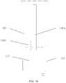
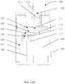
- FIG. 1shows a scent producing imitation candle device in accordance with an exemplary embodiment.
- FIG. 2 Ashows certain components of a scent-producing mechanism within an imitation candle device including a scent chamber and an air pump in accordance with an exemplary embodiment.
- FIG. 2 Bshows an enlarged detailed view of some of the components illustrated in FIG. 2 A .
- FIG. 2 Cshows certain components of a scent-producing mechanism within an imitation candle device including a scent chamber in accordance with an exemplary embodiment.
- FIG. 2 Dshows certain components of a scent-producing mechanism within an imitation candle device including a scent chamber, an air pump, and a check valve in accordance with an exemplary embodiment.
- FIG. 3 Ashows certain components of a scent-producing mechanism within an imitation candle device including a scent chamber and a fan in accordance with an exemplary embodiment.
- FIG. 3 Bshows certain components of a scent-producing mechanism within an imitation candle device including a heating device and a fan in accordance with an exemplary embodiment.
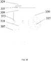
- FIG. 3 Cshows certain components of a scent-producing mechanism within an imitation candle device including an atomizing device and a fan in accordance with an exemplary embodiment.
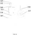
- FIG. 3 Dshows certain components of a scent-producing mechanism within an imitation candle device including an atomizing device in accordance with an exemplary embodiment.
- FIG. 4shows a central control circuit board of an imitation candle device in accordance with an exemplary embodiment.
- FIG. 5 Ashows an external side of an air pump in an imitation candle device in accordance with an exemplary embodiment.
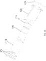
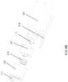
- FIG. 5 Bshows an exploded view of certain components of an imitation candle device in accordance with an exemplary embodiment.
- FIG. 5 Cshows a side view of certain components around an air pump in an imitation candle device in accordance with an exemplary embodiment.
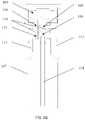
- FIG. 6 Ashows an installation lid of an imitation candle device in accordance with an exemplary embodiment.
- FIG. 6 Bshows an exploded view of components of an installation lid in accordance with an exemplary embodiment.
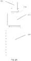
- FIG. 7 Ashows an installation lid and connection pipes of an imitation candle device in accordance with an exemplary embodiment.
- FIG. 7 Bshows an inverted installation lid and connection pipes of an imitation candle device in accordance with an exemplary embodiment.
- FIG. 7 Cshows another installation lid and connection pipes of an imitation candle device in accordance with an exemplary embodiment.
- FIG. 8 Ashows a locking clip and a locking base of an installation lid in accordance with an exemplary embodiment.
- FIG. 8 Bshows another locking clip and another locking base of an installation lid in accordance with an exemplary embodiment.
- FIG. 9 Ashows certain components of a scent-producing mechanism within an imitation candle device including a fragrance container, a scent chamber, and an air pump in accordance with an exemplary embodiment.
- FIG. 9 Bshows certain components of a scent-producing mechanism within an imitation candle device including a fragrance container and a scent chamber in accordance with an exemplary embodiment.
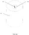
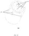
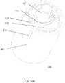
- FIG. 10 Ashows an electronic imitation candle including a flame element in accordance with an exemplary embodiment.
- FIG. 10 Bshows an electronic imitation candle with a retracted flame element and a dark-color component appearing as a wick in accordance with an exemplary embodiment.
- FIG. 11 Ashows certain components of an exemplary electronic imitation candle in accordance with an exemplary embodiment.
- FIG. 11 Bshows certain components of another electronic imitation candle in accordance with an exemplary embodiment.
- FIG. 11 Cshows an enlarged detailed view of some of the components in FIG. 11 B .
- FIG. 12 Ashows an arrangement of a light-emitting component and scent released in the form of smoke in accordance with an exemplary embodiment.
- FIG. 12 Bshows an arrangement of a light-emitting component and scent released in the form of smoke in accordance with an exemplary embodiment.
- FIG. 12 Cshows an arrangement of a light-emitting component and scent released in the form of smoke in accordance with an exemplary embodiment.
- FIG. 13shows a candle device that includes three fragrance containers in accordance with an exemplary embodiment.
- FIG. 14 Ashows a first step of installing a fragrance container in an imitation candle device in accordance with an exemplary embodiment.
- FIG. 14 Bshows a second step of installing a fragrance container in an imitation candle device in accordance with an exemplary embodiment.
- FIG. 14 Cshows a third step of installing a fragrance container in an imitation candle device in accordance with an exemplary embodiment.
- FIG. 14 Dshows an installed fragrance container in an imitation candle device in accordance with an exemplary embodiment.
- exemplaryis used to mean serving as an example, instance, or illustration. Any embodiment or design described herein as “exemplary” is not necessarily to be construed as preferred or advantageous over other embodiments or designs. Rather, use of the word exemplary is intended to present concepts in a concrete manner.
- Imitation candle devicescan simulate a real candle with a flame that resembles a real-life flame with flickering effects using optical, mechanical and electrical components.
- This patent documentdescribes imitation candle devices that are capable of releasing pleasant scents into an external environment.
- FIG. 1illustrates an exemplary scent producing imitation candle device 100 in accordance to technology disclosed herein.
- the device 100includes a flame element 103 and a shell 101 .
- the device 100also includes a scent-producing mechanism positioned within the shell 101 to produce scent and an observation window 126 for the user to see whether there is sufficient scent material.
- FIGS. 2 A- 2 Cshow some exemplary components of a scent-producing mechanism within an imitation candle device 100 .
- a scent producing mechanismincludes a scent chamber 105 .
- the scent chamber 105includes a first channel 108 (shown in FIG. 2 C ) and a second channel 109 (shown in FIGS. 2 A- 2 B ).
- the first channel 108is coupled to (or is in communication with) the air inside a fragrance container 107
- the second channel 109is coupled to (or in communication with) the fragrance inside the fragrance container 107 .
- the scent chamber 105further includes a third channel 110 and a fourth channel 111 .
- the third channel 110is configured to allow outside air to enter the scent chamber 105
- the fourth channelis configured to output a scent produced from the scent chamber 105 to the outside of the candle device 100 .
- the third channel 110is coupled to an air pump 106 to allow air to enter the scent chamber 105 .
- the air pump 106pumps air into the scent chamber 105 via the third channel 110 such that the air pressure of the scent chamber 105 keeps increasing.
- the air in the scent chamber 105enters the fragrance container 107 via the first channel 108 under high air pressure such that the air pressure in the fragrance container 107 keeps increasing as well.
- the fragrance in the fragrance container 107is then transported under pressure into the scent chamber 105 via the second channel 109 .
- the high pressure produced by the air pump 106allows the fragrance to be fully atomized. Because the air pressure in the scent chamber 105 is higher than the air pressure of the external environment, the atomized fragrance leaves the scent chamber 105 via the fourth channel 111 dissipated outside of the candle device, thereby releasing a scent.
- a fanmay be used to supply the air to the third channel 110 , and the fan produces an air flow with a velocity that is directed into the scent chamber 105 .
- the air pumpprovides several advantageous aspects as compared to a fan.
- the air pump 106can effectively drive a fragrance to the second channel 109 inside the electronic candle 100 by producing a high air pressure. Meanwhile, the high air pressure can fully atomize a liquid fragrance, which improves the aromatic effect of the fragrance.
- the atomized fragranceis more concentrated as compared to fragrance dispersed using other mechanisms, e.g., a fan.
- the air pressure produced by the air pump 106is adjustable, thereby allowing the user to adjust the atomization rate of the fragrance. For example, when a fan is used to drive air flow to disperse the liquid fragrance, the magnitude and direction of its pressure on the fragrance may not be precisely controlled even though the wind speed and direction of the fan can be adjusted.
- the air pumpcan apply air pressure of different magnitudes and directions in a relatively precise manner, thereby achieving more effective control by the user.
- an installation lid 113can be used to connect the fragrance container 107 to the scent chamber 105 .
- the installation lid 113includes a fifth channel 115 and a sixth channel 116 (shown in FIG. 2 C ), which are coupled to the first channel 108 and the second channel 109 of the scent chamber 105 , respectively.
- the installation lid 113includes a mount support 117 for mounting the fragrance container 107 in the installation lid 113 .
- the mount support 117is positioned on the installation lid 113 in a removable manner to facilitate easy disassembling of the mount support 117 from the installation lid 113 when the mount support 117 needs to be cleaned.
- the removable connection mechanismincludes, but is not limited to, a snap connection.
- the installation lid 113further comprises a suction tube 118 disposed inside of the mount support 117 .
- the suction tube 118may extend into the mount support 117 and may be coupled to the sixth channel 116 to guide the fragrance in the fragrance container 107 to rise into the scent chamber 105 via the suction tube 118 .
- the suction tube 118is fixed to the mount support 117 through an interference fit between the end of the suction tube 118 and the mount support 117 .
- the mount support 117includes a gasket that may be made of rubber or silica gel, such that an excellent seal can be achieved when the fragrance container 107 is mounted onto the mount support 117 .
- an elastic element 119is further disposed between the installation lid 113 and the mount support 117 .
- the elastic element 119can be used to improve the tightness between the installation lid 113 and the installation.
- the elastic material 119can also reduce vibration of the installation lid 113 and/or the mount support 117 , thereby reducing noise.
- the elastic material 119may be rubber or silica gel.
- the inner side of the mount support 117is of a cylindrical structure and comprises threads to facilitate the fixation of the fragrance container 107 onto the mount support 117 .
- the fragrance container 107has its own threads.
- the threads of the mount support 117allow the use of various types of fragrance containers 107 so long as they have compatible threads, thereby improving the universality of the scent producing device.
- the fragrance container 107may also be fixed through a snap connection.
- the threads of the mount support 117are generally used and therefore can fit most perfume bottles on the market, which also improves the universality of the scent producing device (i.e. a variety of general fragrance containers are compatible with the candle device).
- the first channelis coupled to an air portion inside the fragrance container 107 via the connection pipe 130 B (shown in FIG. 7 B ).
- the opening end of the connection pipe 130 Bis above the surface of the fragrance in the fragrance container 107
- the second channelextends into a fragrance portion inside the fragrance container 107 via the connection pipe 130 A (shown in FIG. 7 A ).
- the fragranceis substantially consumed.
- the electronic candle 100may be inverted so that the installation lid 113 and the fragrance container 107 can be disengaged together, as shown in FIG. 7 B .
- the remaining fragrance in the fragrance container 107then gathers at the opening of the fragrance container 107 . Because the first channel 108 and the second channel 109 are coupled with the connection pipes 130 A and 130 B, whose openings are both higher than the opening of the fragrance container 107 , the perfume will not flow out via the first channel or the second channel.
- the first channel and the second channelare coupled to a fragrance portion inside the fragrance container 107 , as shown in FIG. 7 C .
- the first channel and the second channelextend into a fragrance portion inside the fragrance container 107 via the connection pipe 130 A and the connection pipe 130 B.
- the fragrance container 107is replaced by the user, the electronic candle may be inverted so that the installation lid 113 and the fragrance container 107 can be disengaged together.
- the fragrance in the fragrance container 107then gathers at the opening of the fragrance container 107 .
- the perfumewill not flow out via the first channel or the second channel.
- the connection pipe 130 A and the connection pipe 130 Bextend to the bottom of the fragrance container 107 .
- the fragrance container 107is inclined or inverted, the air inside of the fragrance container 107 moves to the bottom ends of the connection pipe 130 A and the connection pipe 130 B, which can effectively prevent the fragrance from flowing out of the first channel and the second channel in a large quantity.
- connection pipe 130 Bmay be set according to specific requirements, and any connection pipe 130 B higher than the bottle mouth of the fragrance container 107 shall be encompassed by the present document.
- the dimension of one end of the third channel 110 that is further away from the air pump 106can be smaller than the dimension of the remaining portion.
- the shape of the third channel 110includes, but is not limited to, an evenly tapered cone, or a tapered extension in a cylindrical manner from the opening, such that the air flow in the air pump 106 has a further increased velocity when it flows out of the opening into the scent chamber along the third channel 110 .
- the high-speed air flow output from the third channel 110allows the fragrance to be atomized and distributed more evenly.
- the air pump 106can continuously pump at a rate desired by a user.
- the scent producing mechanismmay be set to spray the fragrance intermittently.
- the devicemay spray for five minutes (or another time duration) at every half an hour/one hour/two hour intervals.
- a usermay set the time duration, turn-on time, and turn-off time of spraying.
- the air pump 106is controlled via a control circuitry (such as shown in FIG. 4 ), e.g., through a hardware circuit such as a PCB board.
- a control program for the air pump 106may be written into a memory, and the control program can be executed by a processor to control operations of the air pump 106 .
- the air flow rate by the air pump 106 into the scent chamber 105is greater than or equal to 1.0 L/min. In some implementations, the air flow rate is greater than 1.2 L/min.
- the velocity of the air produced by the air pump 106can be properly controlled to allow the liquid fragrance to be fully atomized while, at the same time, preventing the fragrance to be sprayed too far, such as directly onto the wall of the scent chamber 105 .
- the installation lid 113is provided with a locking clip 121 , such as a lock switch, with a corresponding locking base 120 (see also FIGS. 6 A-B ).
- the locking base 120 and the locking clip 121may be disposed on the top or one side of the installation lid 113 .
- the locking clip 121can form a snap connection with the locking base 120 .
- the locking clip 121is fixed on the scent chamber 105 to form an integral part with the scent chamber 105 .
- the locking base 120has a structure that is wide at the top and narrow at the bottom, similar to a T-shaped structure.
- an installation lid 113is placed onto the fragrance container 107 .
- the installation lid 113 along with the fragrance container 107may, for example, be pushed into an accommodating chamber 104 from the bottom of the electronic candle 100 and snapped into the locking clip 121 . If a user wants to take out the fragrance container 107 , the bottom of the fragrance container 107 may be pressed, then the installation lid 113 along with the fragrance container 107 are disengaged from the locking clip 121 , allowing convenient use.
- the installation lid 113may be placed onto the fragrance container 107 using other means. For example, it may be snapped into the locking clip 121 via the locking base 120 .
- the fragrance container 107When the fragrance container 107 needs to be replaced, the fragrance container 107 may be rotated by an angle such that the installation lid 113 along with the fragrance container 107 are disengaged from the locking clip 121 .
- a limit protrusion 122is formed on a side of the installation lid 113 , such that the installation lid 113 is installed at a fixed angle when being placed into the accommodating chamber 104 , thereby making the installation easier.
- the locking mechanismis not limited to the snap connection or the lock switch as described above. It is also noted that the installation lid 113 and the fragrance container 100 may be installed upward from the bottom.
- the top of the installation lid 113includes a protective layer for covering the fifth channel 115 and the sixth channel 116 (such as shown in FIG. 2 C ).
- the protective layercan be made of silica gel, rubber, or PVC film with a thickness in the range of 0.1-3.5 mm.
- the protective layeris mainly used to prevent the fragrance from flowing out of the fragrance container 107 when the fragrance container 107 is installed for the first time.
- a userneeds to unscrew the lid of the fragrance container 107 , and at the same time, screw on the installation lid 113 installed with the mount support 117 onto the fragrance container 107 in order to replace the original lid of the fragrance container 107 .
- One way of installationis to vertically place the fragrance container 107 with its opening facing upwardly, and then align the accommodating chamber 104 of the electronic candle 100 with the fragrance container 107 .
- the electronic candle device 100can be inverted for the installation. As shown in FIGS. 14 A- 14 D , the electronic candle device 100 is inverted first, and the fragrance container 107 with the installation lid 113 (such as shown in FIGS. 7 A-B ) is also inclined or inverted. Because the installation lid 113 includes a limit protrusion 122 (such as shown in FIGS. 7 A-B ), the fragrance container 107 can be installed into the electronic candle 100 only when the limit protrusion 122 is aligned with the corresponding limit groove. The protrusion 122 of the installation lid 113 enables the fragrance container 107 to be smoothly and precisely installed into the electronic candle 100 , thereby preventing incorrect installation by the user. In addition, such as shown in FIGS.
- a prompt point or indicator 134can be positioned on the bottom of the electronic candle 100 for prompting a user to align the limit projection 122 at the prompt indicator 134 .
- the prompt indicator 134further enables the user to install the fragrance container 107 easily and precisely.
- the protective layer included in the top of the installation lid 113prevents the fragrance from leaking through the suction tube 118 , the fifth channel 115 , and/or the sixth channel 116 on the fragrance container 107 .
- the protective layerwill be in contact with the first channel 108 and/or the second channel 109 .
- the first channel 108 and/or the second channel 109may push through and penetrate the protective layer, allowing the perfume to flow out.
- the first channel 108is now coupled to the fifth channel 115
- the second channel 109is also coupled to the sixth channel 116 . This way, leakage of the fragrance container during installation can be avoided, and normal use of the fragrance container is not affected.
- the bottom of the fragrance container 107is exposed to the outside of the electronic candle 100 . Because the fragrance container 107 is typically made of a transparent material, a user can observe the remaining quantity of the perfume inside the fragrance container 107 from the bottom of the fragrance container 107 .
- any one of the first channel 108 , the second channel 109 , the third channel 110 , the fourth channel, the fifth channel 115 , and/or the sixth channel 116 described abovemay be made of a hard tube, a soft tube, or an elastic material 119 .
- the first channel 108 and/or the second channel 109may be positioned on the scent chamber 105 . In some implementations, they are formed as an integral part of the scent chamber 105 .
- the third channel 110 and/or the fourth channelmay be a soft tube or a hard tube, and the specific material may be plastic, rubber, or PVC. In some embodiments, the third channel 110 and the fourth channel are fixedly disposed on the scent chamber 105 .
- the third channel 110 and/or the fourth channelmay also be formed as an integral part of the scent chamber 105 .
- the fifth channel 115 and the sixth channel 116are fixedly disposed on the installation lid 113 .
- the fifth channel 115 and the sixth channel 116may be formed as an integral part of the installation lid 113 . They can be made of an elastic material 119 , such as rubber or silica gel.
- the external side of the air pump 106includes a sound insulation layer 128 .
- the sound insulation layer 128may be made of sound insulation materials, such as sound insulation cotton, to minimize the noise caused by the air pump 106 .
- the sound insulation materialcan be sound insulation cotton so that the noise produced by the electronic candle 100 is lower than or equal to 55 dB, or lower than or equal to 45 dB. Within such noise limits, the produced noise has a relatively small impact on the users.
- the external side of the air pump 106may include an anti-vibration component(s) 129 so as to minimize the vibration caused by the air pump 106 in the electronic candle 100 , thereby ensuring the stability of electrical contact and visual effect.
- the material for the anti-vibration component(s) 129includes, but is not limited to, silica gel and/or rubber.
- the noise produced by the scent-producing electronic candle 100is lower than or equal to 55 dB, or lower than or equal to 45 dB.
- simultaneous use of sound insulation cotton and an anti-vibration component(s)lowers the noise produced by the electronic candle 100 .
- the air pump 106 and the fragrance container 107are positioned in different chambers of the candle device 100 respectively to avoid severe vibration caused by resonance of the air pump 106 and the fragrance container 107 , thereby reducing the vibration and noise of the product and reducing disruption to the atmosphere.
- the scent chamber 105comprises an opening coupled to one end of the second channel 109 .
- the dimension of the opening of the second channel 109 in the scent chamber 105is smaller than the dimension of the second channel 109 outside of the scent chamber 105 .
- the shape of the openingincludes, but is not limited to, an evenly tapered cone, or a tapered extension in a cylindrical shape, such that the liquid input from the second channel 109 into the scent chamber 105 has a further increased velocity when it leaves the end opening of the second channel 109 .
- the output end opening of the second channel 109is close to the output end opening of the third channel 110 . As a result, the fragrance output via the second channel 109 is fully atomized by the air flow from the third channel 110 , and can be extensively distributed in the scent chamber 105 .
- the internal bottom surface of the scent chamber 105is not set to be a horizontal plane, but a surface inclined towards the inlet of the first channel 108 so as to form a funnel shape near the inlet of the first channel 108 .
- the liquid fragrance suspended on the inner wall of the scent chamber 105can return into the fragrance container 107 , thereby saving the fragrance. Therefore, the high-velocity air flow can fully atomize the fragrance in the embodiments in accordance with the techniques disclosed herein.
- the fragrance that is not fully atomizedmay stay on the inner wall of the scent chamber 105 and ultimately flow back into the fragrance container.
- the path of the fourth channel 111includes a check valve 125 .
- the candle devicefurther includes an inclination sensor 124 , as shown in FIG. 4 .
- the inclination sensor 124can sense the tilt and then shut down the power supply to the air pump 106 .
- the air pressure in the scent chamber 105then quickly decreases to shut down the check valve 125 .
- the liquid fragranceWhen the candle device is tilted or inverted, it is possible for the liquid fragrance to flow into the scent chamber 105 through the first channel 108 , the second channel 109 , the fifth channel 115 , the sixth channel 116 , and the suction tube 118 .
- the scent chamber 105acts as a buffer between other channels (e.g., the first channel 108 , etc.) and the fourth channel 111 such that the liquid fragrance needs to be accumulated to a certain amount in the scent chamber 105 before it can enter the fourth channel 111 and flow out, which requires the candle device to be tilted or inverted for a relatively long time.
- the check valve 125such as the one shown in FIG.
- the inclination sensor 124may include a rolling ball switch, which can be disposed on a circuit board of the candle device or any other places where it can be positioned. The switch of the inclination sensor 124 can turn on or off the power supply to the air pump 106 , either by hardware circuitry or software control.
- an inclination angle thresholdcan be set at, for example, 45 degrees, 75 degrees, or another angle, as the threshold angle formed between the longitudinal axis of the candle device and the vertical axis with respect to the horizon.
- the thresholdcan be used to determine when the inclination sensor 124 should shut down the power supply to the air pump 106 .
- three inclination sensors 124are disposed in a triangular manner with respective to each other on a circuit broad.
- An inclination angle threshold of 45 degrees or 75 degreesis used such that, when the longitudinal axis of the candle device forms an angle, relative to the vertical axis, that is larger than the threshold, the power supply to the air pump 106 is shut down.
- the candle devicedoes not include a first channel. Instead, the fragrance goes through the suction tube 218 and a corresponding second channel 209 into the scent chamber 105 directly.
- the scent chambermay include, or can be replaced by, a water-absorbing material 228 at the location where the suction tube 218 , the scent-releasing opening 229 , and the seventh channel 230 meet.
- the water-absorbing material 228can be used for transporting the liquid fragrance in the fragrance container 207 to an external environment of the candle device.
- the water-absorbing material 228includes, but is not limited to, cotton, sponge, etc. The water-absorbing material 228 absorbs the liquid fragrance and helps it evaporate into the air. In the embodiment shown in FIG.
- a fan 227is used to accelerate the evaporation of the fragrance.
- the air pump 206may also be used to accelerate the evaporation of the fragrance.
- Such embodiments as shown in FIG. 3 Arequire fewer components, thereby allowing the candle device to be smaller and more compact.
- the candle devicedoes not include a first channel. Instead, the fragrance goes through the suction tube 318 and/or a corresponding second channel 309 into the scent chamber directly.
- the scent chambermay be replaced by a heating device 331 or an atomizing device 332 at the location where the suction tube 318 , the scent-releasing opening 328 , and the seventh channel 330 meet.
- the heating device 331 or the atomizing device 332can be used for transporting the liquid fragrance in the fragrance container 307 to an external environment of the candle device.
- a fan 327is used to accelerate the evaporation of the scent.
- the heating device 331heats and helps the fragrance to evaporate.
- the heatfacilitates the fragrance to evaporate more quickly and evenly.
- the heating device 331may also produce smoke during the process of heating, mimicking a visual effect of a real flame.
- the heating device 331may include an electric heating wire, a Positive Temperature Coefficient (PTC) heating element, a semiconductor or electromagnetic heating module, and other electric heating elements.
- PTCPositive Temperature Coefficient
- the electronic candle 100further comprises a smoke generator 131 .
- the smoke generator 131is used to further atomize the fragrance and/or additional liquid scent to a smoke.
- the smoke generator 131can be the atomizing device 332 as shown in FIGS. 3 C- 3 D .
- the smoke generator 131works with a control circuit 133 , and the control circuit 133 can be used to detect actions of a user, such as “blowing off,” “turning off fan,” or “turning off device.” In some implementations, when the electronic candle 100 is turned on, the smoke generator 131 does not produce smoke.
- the control circuit 133When the control circuit 133 detects an action of “blowing off,” “turning off fan,” or “turning off device,” the control circuit 133 sends a signal to the control circuitry 132 , which controls, according to the signal, the smoke generator 131 to produce smoke when the electronic candle 100 is “extinguished” to simulate the smoke produced when a real candle is extinguished.
- the smoke generator 131may also continuously produce smoke when the electronic candle 100 is turned on so that, when the electronic candle 100 is lit, a scent is released and accompanied by a smoke to simulate the smoke produced when a real candle is burning.
- the smokee.g. a thin smoke
- the smoke generator 131is released from the through hole 102 .
- the shell 101includes a plurality of holes to allow the smoke to be released.
- the smoke generator 131is electrically coupled to the control circuitry 132 to control the smoke generator 131 .
- the smoke generator 131is an ultrasonic atomizer. After being activated by an electric signal, the ultrasonic atomizer produces high-frequency harmonic oscillations, which cause a porous metal membrane adhered to the ultrasonic atomization piece to produce ultrasonic vibration through energy transfer, causing the liquid adsorbed to the metal membrane to be atomized.
- Such smoke generator 131does not require heating or adding a chemical reagent, and thus can be more energy-efficient than atomization techniques that use heat.
- Such smoke generator 131also has characteristics such as low noise, long service life, and low power consumption.
- the smoke produced by the smoke generator 131may appear like real smoke from a real candle. It is noted that the smoke generator 131 can be implemented using other compatible smoke generation structures and techniques that operate based pressurized atomization, static atomization, ultrasonic atomization, bubble atomization, rotary atomization, annular hole atomization, etc.
- the light-emitting element 112 of the electronic candle 100may be an LED lamp.
- FIGS. 12 A- 12 Cshow some embodiments in which the light emitted by at least one LED lamp illuminates the smoke produced during the heating process through a through hole.
- the smokecan be blown out of the candle device through the through hole by the air pump or the fan.
- the illumination of the LED light cast on changing shapes of the smokecan make the flames look like real flames of a burning candle.
- the LED lightmay be installed on one side of the flame element 103 , such as shown in FIG. 12 A .
- the LED lightmay be installed on two sides of the flame element 103 , such as shown in FIG. 12 B .
- the LED lightmay be installed on the bottom of a support structure that supports the flame element 103 , such as shown in FIG. 12 C .
- the light-emitting element 112may also be a halogen lamp, which can facilitate the evaporation of the fragrance by the heat of the lamp itself. The warm color of the halogen lamp and the heated smoke give the candle device a more appealing appearance of a real burning candle.
- the atomizing device 332atomizes the fragrance, which is blown out by the air pump or the fan 337 such that the fragrance can evaporate more evenly.
- FIG. 3 Cthe atomizing device 332 atomizes the fragrance, which is blown out by the air pump or the fan 337 such that the fragrance can evaporate more evenly.
- the atomizing device 332directly atomizes the fragrance, which is released into the external environment by the scent-releasing opening.
- Embodiments such as the one shown in FIG. 3 Crequire fewer components so that the candle device can be made smaller and more compact.
- the scent-producing candle deviceincludes a fragrance container 107 , a first channel 108 coupled to an air inside the fragrance container 107 , and a second channel 109 coupled to a fragrance inside the fragrance container 107 .
- the fragrance container 107can be a bottle containing a liquid fragrance, such as perfume or essential oil.
- the air pump 106pumps air into the scent chamber 105 via the third channel 110 .
- FIG. 13shows an example of a candle device that includes three fragrance containers 107 .
- a plurality of scent chamberscan be used so that each scent chamber is connected to each of the plurality of fragrance containers 107 .
- a plurality of fourth channelscan be connected to the plurality of scent chambers to allow the scent to be transported to an external environment.
- one scent chamberis connected to the plurality of fragrance containers 107 .
- Another channelis connected to the scent chamber to allow the fragrance to be transported to the outside.
- a usermay choose his or her favorite customized scent by mixing and matching various fragrance stored in the plurality of fragrance containers.
- Different scentscan either be mixed before being sent to an external environment, or be sent to an external environment and then mixed in the air, both of which can further improve the diversity and the effect of scents.
- an electronic candle 100includes a shell 101 , a through hole 102 on the top of the shell 101 , a flame element 103 running through the through hole 102 and extending outwardly from the inside of the through hole 102 .
- the inside of the shell 101is constructed to accommodate a fragrance container 107 , a first channel 108 coupled to the air inside the fragrance container 107 , and a second channel 109 coupled to a fragrance inside the fragrance container 107 .
- the shell 101may be used for installation and fixation of various components inside the electronic candle 100 .
- the shell 101may be used to support a bracket to hold a light-emitting element and a coil for driving a flame piece to sway.
- the candle device 100includes an accommodating chamber 104 within the shell 101 .
- the scent-producing mechanismincludes a scent chamber 105 .
- the scent chamber 105further includes a first channel (not shown) and a second channel 109 .
- the first channelis constructed to be coupled to the air inside a fragrance container 107
- the second channel 109is constructed to be coupled to a fragrance inside the fragrance container 107 .
- the scent chamber 105may also include a third channel 110 and a fourth channel 111 .
- the third channel 110is constructed to input the air to the scent chamber 105
- the fourth channelis constructed to output a scent produced in the scent chamber 105 to the outside of the electronic candle 100 .
- the fragrance container 107 located within the accommodating chamber 104can be a bottle containing a liquid fragrance, such as perfume or essential oil.
- the accommodating chamber 104may also be used to accommodate a container holding a solid fragrance, such as a scent block.
- the air pump 106pumps air into the scent chamber 105 via the third channel 110 .
- the air pump 106can be disposed inside the shell 101 . Alternatively, the air pump 106 may also be disposed outside the shell.
- the airenters the scent chamber 105 via the third channel 110 .
- the air pump 106pumps the air into the third channel 110 such that the air pressure of the scent chamber 105 keeps on increasing. Under the higher air pressure, the air in the scent chamber 105 then enters the fragrance container 107 via the first channel 108 , causing the air pressure in the fragrance container 107 to increase as well. The fragrance in the fragrance container 107 is then transported under pressure into the scent chamber 105 via the second channel 109 to be fully atomized. Because the air pressure in the scent chamber 105 is also higher than the air pressure of the external environment of the electronic candle 100 , the atomized fragrance is released via the fourth channel to the outside of the electronic candle 100 .
- the embodiments that use an air pumphave the following advantages.
- the electronic candle 100 in accordance with the techniques disclosed hereincan effectively drive a fragrance to the second channel 109 inside the electronic candle 100 by the air pressure produced by the air pump 106 .
- the air pressure of the air pump 106itself can fully atomize a liquid fragrance, which improves the aromatic effect of the fragrance.
- the atomized fragrancecan also appear as smoke produced when the candle device 100 is “burning.”
- the atomized fragranceis more concentrated as compared to fragrance dispersed using other mechanisms, e.g., a fan.
- the air pressure produced by the air pump 106is adjustable, thereby allowing the user to adjust the atomization rate of the fragrance.
- the magnitude and direction of its pressure acting on the fragrancemay not be precisely controlled even though the wind speed and direction of the fan can be adjusted.
- the air pumpcan apply air pressure of different magnitudes and directions in a relatively precise manner, thereby achieving more effective control by the user.
- the atomized fragrancecan appear like a smoke that is produced by a real burning candle, achieving a more realist look and feel.
- the air pumpcan pump the fragrance at a higher speed to produce a burst of smoke so that the candle device appears to be extinguished like a real candle.
- the shell 101has an appearance similar to a conventional candle.
- the cross section of the shell 101may have a triangular, square, oval, or irregular shape.
- the shell 101may be made of any one of the materials such as wax, paraffin, plastics, glass, metal, ceramic, crystal, and polymers, or any combination thereof.
- the top of the shell 101may be a substantially flat surface, or have a recess, to simulate a brand-new unused candle.
- the shell 101may also include additional shapes, such as solidified flows of melted wax, formed on its surface so as to simulate a used candle.
- the top of the electronic candle 100includes a through hole 102 , and the flame element 103 extends outwardly from inside the shell 101 via the through hole 102 .
- the candle device 100comprises an accommodating chamber 104 and a fragrance container 10 positioned in the accommodating chamber 104 .
- the fragrance container 107may pre-installed in the electronic candle 100 during manufacturing or packaging.
- the electronic candle 100may not carry the fragrance container 107 . Instead, a user may install it on his/her own into the accommodating chamber 104 according to his/her preferences of fragrances.
- the accommodating chamber 104may have a shape of a cuboid or a cube to accommodate a plurality of fragrance containers 107 , such as shown in FIG. 13 .
- the accommodating chamber 104may have a shape of a ring such that the plurality of fragrance containers 107 are evenly or unevenly distributed along the ring-shaped space in the chamber 104 .
- one end of the third channel 110is connected to the scent chamber 105 , and the other end of the third channel 110 extends to the through hole 102 to release the scent out of the electronic candle 100 .
- the shell 101may include a plurality of scent-releasing openings disposed at different positions of the shell.
- the other end of the third channel 110may extend to other places of the electronic candle 100 .
- the electronic candle 100can be suspended using a support mechanism.
- the other end of the third channel 100may extend to the bottom of an electronic candle 100 to release scent from the bottom of the candle.
- the support mechanismcan be a magnetic levitation mechanism.
- one or more additional through hole(s)can be formed at the bottom of the electronic candle to allow convection of the air and the fragrance in the electronic candle 100 to enable a smoother spray of the scent from the electronic candle 100 .
- the upper portion of the flame element 103has a flame shape and can make irregular movements.
- the flame element 103randomly sways to simulate of the movements of a real flame.
- the flame element 103includes a dark-colored section 123 to simulate a real candle wick after burning.
- the control circuit 133when the control circuit 133 detects one of the following actions of “blowing off,” or “turning off the fan,” or “turning off the device”, the control circuit 133 sends a signal to the control circuitry 132 , which controls the smoke generator 131 according to the signal to produce smoke when the electronic candle is extinguished to simulate the smoke produced when a real candle is extinguished.
- the flame element 103may retract, as shown in FIGS. 10 A- 10 B , and the dark-colored section 123 of the flame element 103 extends outside of the through hole 102 to simulate a real candle wick after burning.
- the dark-colored section 123may still remain outside of the through hole 102 , and/or may slightly rise outside of the through hole 102 .
- the flame shape on the upper portion of the flame element 103can be a sheet-like flame, or may be combined by two or more sheet-like flames, or may have a 3 D shape.
- the flame element 103may be made of plastic or an organic synthetic material.
- the flame element 103is made of a translucent material, such that the flame can be seen from both sides of the flame piece.
- the flame piece on the upper portion of the flame element 103has an uneven thickness to simulate lighting effects of a flame at different heights. For example, the flame piece is thin at the top and thick at the bottom. For another example, the flame piece is thin at the top, thick in the middle, and thin at the bottom.
- the flame element 103includes a pivot hole (not shown).
- a support elemente.g., a rigid V-shaped rod, goes through the pivot hole to support the flame element 103 .
- the distances between the lowest point of the support element and two endsare not equal.
- the light source 112can be positioned at the end that has a shorter distance to allow better illumination of the flame-shaped portion.
- the support elementmay be a soft wire, and two ends of the support element can be fixed to the shell 101 such that the flame element 103 can pivot about the support element.
- the lower portion of the flame element 103may have a magnet or a magnetic material, such that the flame element can make nonlinear movements varying with time under the action of the magnetic field.
- the flame element 103is driven by other mechanisms such as air flow (e.g., from a fan) or gas flow from the outside.
- the electronic candle 100further comprises a remote control module 136 .
- a usercan send an electric signal to the remote control module 136 using a remote control device.
- the remote control module 136receives the electric signal and sends a signal to the control circuitry 132 , and the control circuitry 132 controls, according to the signal, the electronic candle 100 to turn the electronic candle 100 on or off and to perform other controls of the device.
- the electronic candle 100further comprises a power supply.
- the power supplymay be formed by providing a battery chamber to accommodate one or more dry cells or re-chargeable batteries. In the case of a rechargeable battery, the battery can be charged in a wired charging mode. In some embodiments, the power supply may also be charged in a wireless charging mode. In some implementations, the power supply may be charged with solar energy; such solar energy is converted into electrical energy for storage when the product is not in use, and the electrical energy can be supplied to the electronic candle 100 during use. In some embodiments, the power supply may include a plug that is directly connected to an AC outlet so as to supply power to the electronic candle 100 .
- the bottom of the electronic candle 100includes a plurality of support components 128 (e.g., legs).
- the plurality of support components 128are separated from one another by corresponding gaps.
- a power supply connection 129is formed in the center bottom of the electronic candle 100 , where a can be connected to the power supply connection 129 .
- the spacing between the support components 128allows the power cord to reach the electronic candle while the electronic candle is placed on a flat surface. The user may select, according to the desired position and direction of the electronic candle 100 , the appropriate gap for routing the power cord.
- the shell 101 of the electronic candle 100includes at least one observation window 126 to observe the remaining quantity of fragrance in the fragrance container 107 .
- the shell 101includes a plurality of observation windows 126 , each corresponding to one of the plurality of fragrance containers 107 .
- the observation window 126is made of a clear plastic.
- the observation window 126may have a specific shape such as, but not limited to, a rectangle, a rhombus, an ellipse, and the like.
- a light source 127may be provided in the electronic candle 100 . The light source 127 can illuminate the body of the fragrance container 107 such that the quantity of remaining fragrance can be observed.
- the fragrance container 107may hold a liquid fragrance.
- the fragrant containermay also hold a scented bead, a scented block, etc.
- the fragrance container 107may simply contain water. When the water is atomized, it can humidify the air and achieve an effect similar to that of a humidifier.
Landscapes
- Health & Medical Sciences (AREA)
- Epidemiology (AREA)
- Life Sciences & Earth Sciences (AREA)
- Animal Behavior & Ethology (AREA)
- General Health & Medical Sciences (AREA)
- Public Health (AREA)
- Veterinary Medicine (AREA)
- Engineering & Computer Science (AREA)
- General Engineering & Computer Science (AREA)
- Disinfection, Sterilisation Or Deodorisation Of Air (AREA)
Abstract
Description
Claims (13)
Priority Applications (3)
| Application Number | Priority Date | Filing Date | Title |
|---|---|---|---|
| US16/420,459US11519575B2 (en) | 2017-04-01 | 2019-05-23 | Scented imitation candle device |
| US18/061,608US12287073B2 (en) | 2017-04-01 | 2022-12-05 | Scented imitation candle device |
| US19/191,756US20250251101A1 (en) | 2017-04-01 | 2025-04-28 | Scented imitation candle device |
Applications Claiming Priority (4)
| Application Number | Priority Date | Filing Date | Title |
|---|---|---|---|
| CN201710214532.9ACN108653785B (en) | 2017-04-01 | 2017-04-01 | Fragrance generating device, fragrance device and electronic candle |
| CN201710214532.9 | 2017-04-05 | ||
| US15/886,781US10302263B2 (en) | 2017-04-01 | 2018-02-01 | Scented imitation candle device |
| US16/420,459US11519575B2 (en) | 2017-04-01 | 2019-05-23 | Scented imitation candle device |
Related Parent Applications (1)
| Application Number | Title | Priority Date | Filing Date |
|---|---|---|---|
| US15/886,781ContinuationUS10302263B2 (en) | 2017-04-01 | 2018-02-01 | Scented imitation candle device |
Related Child Applications (1)
| Application Number | Title | Priority Date | Filing Date |
|---|---|---|---|
| US18/061,608DivisionUS12287073B2 (en) | 2017-04-01 | 2022-12-05 | Scented imitation candle device |
Publications (2)
| Publication Number | Publication Date |
|---|---|
| US20200116321A1 US20200116321A1 (en) | 2020-04-16 |
| US11519575B2true US11519575B2 (en) | 2022-12-06 |
Family
ID=63710861
Family Applications (4)
| Application Number | Title | Priority Date | Filing Date |
|---|---|---|---|
| US15/886,781ActiveUS10302263B2 (en) | 2017-04-01 | 2018-02-01 | Scented imitation candle device |
| US16/420,459Active2039-03-20US11519575B2 (en) | 2017-04-01 | 2019-05-23 | Scented imitation candle device |
| US18/061,608ActiveUS12287073B2 (en) | 2017-04-01 | 2022-12-05 | Scented imitation candle device |
| US19/191,756PendingUS20250251101A1 (en) | 2017-04-01 | 2025-04-28 | Scented imitation candle device |
Family Applications Before (1)
| Application Number | Title | Priority Date | Filing Date |
|---|---|---|---|
| US15/886,781ActiveUS10302263B2 (en) | 2017-04-01 | 2018-02-01 | Scented imitation candle device |
Family Applications After (2)
| Application Number | Title | Priority Date | Filing Date |
|---|---|---|---|
| US18/061,608ActiveUS12287073B2 (en) | 2017-04-01 | 2022-12-05 | Scented imitation candle device |
| US19/191,756PendingUS20250251101A1 (en) | 2017-04-01 | 2025-04-28 | Scented imitation candle device |
Country Status (2)
| Country | Link |
|---|---|
| US (4) | US10302263B2 (en) |
| CN (1) | CN108653785B (en) |
Cited By (1)
| Publication number | Priority date | Publication date | Assignee | Title |
|---|---|---|---|---|
| US12287073B2 (en)* | 2017-04-01 | 2025-04-29 | L&L Candle Company, Llc | Scented imitation candle device |
Families Citing this family (15)
| Publication number | Priority date | Publication date | Assignee | Title |
|---|---|---|---|---|
| CN109140367B (en) | 2017-06-17 | 2025-06-27 | 深圳市里阳电子有限公司 | Electronic scented candles and fragrance containers |
| EP3730834A4 (en)* | 2017-12-21 | 2021-08-25 | Guangdong Lighting Silk Roads Cultural Development Co., Ltd. | Electronic simulation candle |
| US10352515B1 (en)* | 2018-01-15 | 2019-07-16 | Shunning Yin | Simulated flame tip and simulated candle |
| CN109595993B (en)* | 2019-01-31 | 2023-05-16 | 深圳市金泰坦科技有限公司 | Electronic firework spraying control device and electronic firework spraying system |
| WO2020186018A1 (en)* | 2019-03-12 | 2020-09-17 | Scentair Technologies, Llc | Fragrance diffusion collector assembly, exchangeable fragrance cartridge, and fragrance diffusion system and method |
| CN211289899U (en)* | 2019-12-17 | 2020-08-18 | 深圳市里阳电子有限公司 | Fragrance electronic candle |
| DE102020118422A1 (en)* | 2020-07-13 | 2022-01-13 | Bayerische Motoren Werke Aktiengesellschaft | Fragrance and disinfectant dispensers in the vehicle |
| CN112344288B (en) | 2020-11-04 | 2023-07-14 | 曹丽玲 | simulation candle |
| US11841134B2 (en)* | 2020-11-26 | 2023-12-12 | Yu-Wen YEN | Composite lighting device of scent atomization module |
| US12161107B2 (en)* | 2021-05-06 | 2024-12-10 | Lamplight Farms Incorporated | Aerosol dispenser |
| US11920746B2 (en)* | 2021-06-24 | 2024-03-05 | Ulta-Lit Tree Company | Flameless LED candle with flickering effect and fan-driven scent diffuser |
| CA3229349A1 (en)* | 2021-09-15 | 2023-03-23 | Peter G. Spiegel | Diffuser having multiple atomizers with a single pump |
| CN115597152B (en)* | 2022-10-24 | 2024-08-23 | 珠海格力电器股份有限公司 | Humidifier |
| CN116271170A (en)* | 2023-01-18 | 2023-06-23 | 深圳市好奇探索科技有限公司 | Smoke aromatherapy machine |
| CN220601475U (en)* | 2023-08-28 | 2024-03-15 | 深圳市杰伟祥和实业有限公司 | A Bluetooth speaker desk lamp with essential oil aromatherapy |
Citations (205)
| Publication number | Priority date | Publication date | Assignee | Title |
|---|---|---|---|---|
| US782156A (en) | 1904-06-06 | 1905-02-07 | Charles E Meeker | Dancing toy or figure. |
| US817772A (en) | 1905-09-21 | 1906-04-17 | Robert Helmer | Dancing toy. |
| US1507371A (en) | 1924-09-02 | A cokpobatiow | ||
| US1842167A (en) | 1929-09-09 | 1932-01-19 | Westinghouse Lamp Co | Candle lamp |
| US1955042A (en) | 1933-03-20 | 1934-04-17 | Shirley A Work | Light structure |
| US2435811A (en) | 1945-03-30 | 1948-02-10 | Harry E Waters | Artificial candle |
| US2932351A (en) | 1958-06-02 | 1960-04-12 | Julien A Bried | Vertical slat blind suspension |
| US2976450A (en) | 1957-08-22 | 1961-03-21 | Osmond D Benoliel | Flickering electric candle |
| US2984032A (en) | 1958-09-15 | 1961-05-16 | Cornell Frederick Stuart | Artificial fireplace apparatus |
| US3233093A (en) | 1963-09-25 | 1966-02-01 | Matthew E Gerlat | Processional candle |
| US3384774A (en) | 1965-07-09 | 1968-05-21 | Gen Electric | Decorative pulsating flame incandescent lamp |
| US3425157A (en) | 1966-04-01 | 1969-02-04 | William H Hartsock | Magnetic toy or similar apparatus |
| DE1489617A1 (en) | 1965-11-20 | 1969-05-14 | Witte & Sutor Gmbh | Electric candle with flame effect |
| US3514660A (en) | 1968-07-10 | 1970-05-26 | Sylvania Electric Prod | Electric discharge flicker lamp |
| US3603013A (en) | 1968-02-06 | 1971-09-07 | Radiation Sunhouse Ltd | Electric illumination devices |
| US3639749A (en) | 1968-01-10 | 1972-02-01 | Bengt Erling Beckman | Imitation candle |
| US3681588A (en) | 1970-11-16 | 1972-08-01 | Carolina Enterprises | Candelabrum and light transmitting means therefor |
| US3814973A (en) | 1972-09-05 | 1974-06-04 | Duro Test Corp | Electric lamps of the vibrating filament type having a conductive coating |
| US3890085A (en) | 1971-12-27 | 1975-06-17 | Frits J Andeweg | Illuminated candle structure |
| US4026544A (en) | 1976-05-05 | 1977-05-31 | Plambeck H Robert | Burning logs simulator |
| US4067111A (en) | 1975-05-12 | 1978-01-10 | Truitt Thomas E | Pendulum device |
| US4328534A (en) | 1979-10-08 | 1982-05-04 | Kabushiki Kaisha Sofard | Candle type illuminating lamp |
| WO1982002756A1 (en) | 1981-01-29 | 1982-08-19 | Dahlgren Ake | Imitated stearin candle |
| US4477249A (en) | 1983-04-29 | 1984-10-16 | Zdenka Ruzek | Flame-producing sound-emitting device |
| EP0138786A1 (en) | 1983-09-21 | 1985-04-24 | Feeling's Flame International AB | An imitation candle |
| WO1985003561A1 (en) | 1984-01-31 | 1985-08-15 | Beckman, Bengt, Erling | Mechanism for candle-light imitations with easy movable mounted bulbs |
| US4550363A (en) | 1983-09-21 | 1985-10-29 | Sven Sandell | Candle simulating light bulb cover |
| US4617614A (en) | 1985-09-16 | 1986-10-14 | Gabor Lederer | Electric light fixture |
| WO1987004506A1 (en) | 1986-01-23 | 1987-07-30 | Rolf Berg | Imitation lighted candle |
| US4728871A (en) | 1985-11-01 | 1988-03-01 | Andrews Roger W | Novelty electric motor |
| US4777571A (en) | 1987-05-18 | 1988-10-11 | Morgan Clint E | Christmas tree lighting utilizing fiber optics |
| CN1030823A (en) | 1987-07-22 | 1989-02-01 | 罗尔夫·伯格 | Artificial lighting candle |
| US4866580A (en) | 1988-04-25 | 1989-09-12 | Carol Blackerby | Ornamental lighting device |
| GB2230335A (en) | 1989-02-10 | 1990-10-17 | Basic Engineering Ltd | Apparatus for simulating flames |
| US4968487A (en) | 1986-09-02 | 1990-11-06 | Fumakilla Limited | Heat fumigation apparatus |
| US5072208A (en) | 1990-07-02 | 1991-12-10 | Christensen John J | Electromechanical chaotic chiming mechanism |
| US5097180A (en) | 1990-09-14 | 1992-03-17 | Roger Ignon | Flickering candle lamp |
| US5152602A (en) | 1992-01-30 | 1992-10-06 | Andrew Boschetto | Electric candle |
| GB2267746A (en) | 1992-01-29 | 1993-12-15 | Martin Chung | Electric candle with sound producing means |
| JPH0652709A (en) | 1992-06-05 | 1994-02-25 | Hiroshi Otani | Ornamental lighting fixture |
| US5381325A (en) | 1993-02-19 | 1995-01-10 | Messana; Joseph | Self-positioning lamp fixture with stabilizing base |
| WO1996025624A1 (en) | 1995-02-15 | 1996-08-22 | Rolf Berg | Light system |
| US5707282A (en) | 1996-02-28 | 1998-01-13 | Hewlett-Packard Company | Fan diffuser |
| JPH1057464A (en) | 1996-08-26 | 1998-03-03 | Chihiro Asakura | Electric aromatization device for popli |
| EP0855189A2 (en) | 1997-01-13 | 1998-07-29 | Mutsuo Hirano | Diffuser |
| GB2323159A (en) | 1997-02-21 | 1998-09-16 | Paul Alan Harrison | Simulated flame device |
| US5924784A (en) | 1995-08-21 | 1999-07-20 | Chliwnyj; Alex | Microprocessor based simulated electronic flame |
| JP2000284730A (en) | 1999-03-30 | 2000-10-13 | Seiko Clock Inc | Pendulum drive |
| US6198229B1 (en) | 1996-02-01 | 2001-03-06 | Mccloud Kevin | Luminescent control by sensing wind speed |
| US6241362B1 (en) | 1999-07-19 | 2001-06-05 | David J. Morrison | Lighted display emitting variable colors |
| US6257755B1 (en) | 1998-12-10 | 2001-07-10 | Taja Sevelle | Compact butter maker |
| US6302555B1 (en) | 1997-05-31 | 2001-10-16 | Burley Appliances Limited | Apparatus for simulating flames |
| US6312137B1 (en) | 2000-10-12 | 2001-11-06 | Hua Lung Hsieh | Structure of the ornament lamp |
| WO2001092780A1 (en) | 2000-05-30 | 2001-12-06 | New Feeling's Flame Ab | Electrical candles |
| CN2483103Y (en) | 2000-11-21 | 2002-03-27 | 董建屏 | Candlelight fountain |
| US20020080601A1 (en)* | 2000-12-22 | 2002-06-27 | Meltzer Otto Wilhelm | Device for simulating an open fire |
| US6454425B1 (en) | 2001-07-10 | 2002-09-24 | Superstar Lighting Co., Ltd. | Candle simulating device having lighting device |
| US6461011B1 (en) | 1999-02-15 | 2002-10-08 | Paul Alan Harrison | Simulated flame device |
| US6511219B2 (en) | 1997-12-10 | 2003-01-28 | Taja Sevelle | Compact butter maker |
| WO2003011349A1 (en) | 2001-08-01 | 2003-02-13 | Givaudan Sa | Fragrance device |
| GB2379731A (en) | 2001-09-15 | 2003-03-19 | Albert Edward Bridgman | Simulated flame device |
| CN2551859Y (en) | 2002-04-30 | 2003-05-21 | 安特威电子(东莞)有限公司 | A LED decorative fire lamp |
| CN2562059Y (en) | 2002-04-30 | 2003-07-23 | 安特威电子(东莞)有限公司 | Color Changing Smoke Flame Lamp |
| GB2385413A (en) | 2002-02-19 | 2003-08-20 | Robert John Stockwell | An imitation fire with a fabric flame effect driven by a motor and extension arm assembly |
| US6688752B2 (en) | 2001-10-11 | 2004-02-10 | Wayne T. Moore | Electronically simulated flame |
| USD486924S1 (en) | 2002-10-18 | 2004-02-17 | Lumenworks Lighting Products, Inc. | Candles flame simulating light |
| US6712493B2 (en) | 2002-04-03 | 2004-03-30 | Tell Design | Method and apparatus for producing an illuminated animation effect |
| US6757487B2 (en) | 1999-01-14 | 2004-06-29 | Cfm Corporation | Electric fireplace with light randomizer, filter and diffuser screen |
| US6781270B2 (en) | 2001-05-09 | 2004-08-24 | Harmonic Drive, Inc. | Magnetically coupled dangling apparatus |
| CN1530142A (en) | 2003-03-10 | 2004-09-22 | 北京亚都科技股份有限公司 | Fragrance releaser |
| CN1646177A (en) | 2002-04-18 | 2005-07-27 | 松下电器产业株式会社 | Aromaizer |
| US6953401B2 (en) | 2002-04-04 | 2005-10-11 | Technifex Products, Llc | Apparatus for producing a fire special effect |
| US6955440B2 (en) | 2003-08-15 | 2005-10-18 | Will Niskanen | Decorative light defusing novelty lamp |
| US6966665B2 (en) | 2003-06-27 | 2005-11-22 | S. C. Johnson & Son, Inc. | Flameless candle with air intake chamber and air outflow chamber |
| WO2006020839A2 (en) | 2004-08-10 | 2006-02-23 | Disney Enterprises, Inc. | System and method for generating a flickering flame effect |
| US7029146B2 (en) | 2002-04-22 | 2006-04-18 | Edward F. Kitchen | Flameless candle |
| US7066637B2 (en) | 2003-07-07 | 2006-06-27 | Chaotic Toys Factory Ltd. | Imitation flame generating apparatus and method |
| US7080472B2 (en) | 2002-09-27 | 2006-07-25 | Napoleon Systems And Develpements Inc. | Flame simulating apparatus |
| US7080762B1 (en) | 2004-07-14 | 2006-07-25 | Glovebuster, Llc | Leather softening apparatus for baseball gloves |
| US7083315B2 (en) | 2001-03-26 | 2006-08-01 | Siemens Airfield Solutions | Elevated airfield runway and taxiway edge-lights utilizing light emitting diodes |
| US7093949B2 (en) | 2003-01-29 | 2006-08-22 | Givaudan Sa | Imitation flame air freshener |
| US7111421B2 (en) | 2001-05-22 | 2006-09-26 | Corry Arthur A | Simulated log burning fireplace apparatus |
| US7118243B2 (en) | 2004-03-16 | 2006-10-10 | Jenesis International, Inc. | Wax shell imitation candle with improved resistance to cracking |
| US7125142B2 (en) | 2003-05-06 | 2006-10-24 | Harry Lee Wainwright | Flame simulating device |
| CN2854329Y (en) | 2005-10-11 | 2007-01-03 | 李晓锋 | Electronic analogue flash candle |
| US7159994B2 (en) | 2004-08-10 | 2007-01-09 | Disney Enterprises, Inc. | System and method for generating a flickering flame effect |
| CN2888274Y (en) | 2006-03-17 | 2007-04-11 | 李晓锋 | Electronic acousto-optic device |
| USD545458S1 (en) | 2006-03-22 | 2007-06-26 | The Lamson & Sessions Co. | Artificial candle |
| CN200940808Y (en) | 2006-05-11 | 2007-08-29 | 李晓锋 | Electronic acousto-optic device |
| EP1838110A1 (en) | 2006-03-24 | 2007-09-26 | Flap Co. Ltd. | Three dimensional image presenting apparatus, system and method |
| US7300179B1 (en) | 2007-01-04 | 2007-11-27 | Disney Enterprises, Inc. | Light sheet display using light strips with adjustable positions and orientations |
| US7305783B2 (en) | 2001-05-16 | 2007-12-11 | Hni Technologies Inc. | Lenticular fireplace |
| CN201011621Y (en) | 2006-05-11 | 2008-01-23 | 李晓锋 | MP3 electronic acousto-optic device |
| JP2008018075A (en) | 2006-07-13 | 2008-01-31 | Samii Kk | Game machine |
| US7350720B2 (en) | 2004-02-03 | 2008-04-01 | S.C. Johnson & Son, Inc. | Active material emitting device |
| US7360935B2 (en) | 2005-03-31 | 2008-04-22 | Winvic Sales, Inc. | Imitation candle with simulated lighted wick |
| USD567993S1 (en) | 2006-12-02 | 2008-04-29 | Gold Coral International Limited | Rechargeable candle light combination |
| CN201059432Y (en) | 2007-08-07 | 2008-05-14 | 王祖凡 | Multifunctional wax lamp based on using common candles |
| GB2443926A (en) | 2006-11-16 | 2008-05-21 | Sap Products Ltd | Electronic candle |
| CN201093300Y (en) | 2007-10-08 | 2008-07-30 | 唐炳隆 | Electric candle lamp |
| WO2008092753A2 (en) | 2007-01-30 | 2008-08-07 | Basic Holdings | Flame effect generator for electric fire |
| CN201103952Y (en) | 2007-05-22 | 2008-08-20 | 广东亿龙电器股份有限公司 | Electric fireplace |
| USD576317S1 (en) | 2006-03-27 | 2008-09-02 | The Lamson & Sessions Co. | Glowing artificial candle flame |
| CN201159425Y (en) | 2007-12-29 | 2008-12-03 | 程明 | A simulated electronic candle |
| USD589176S1 (en) | 2008-10-16 | 2009-03-24 | Osram Sylvania, Inc. | Light emitting diode-based lamp |
| CN101408284A (en) | 2008-11-17 | 2009-04-15 | 朱福龙 | Remote control electric candle |
| CN201235095Y (en) | 2008-07-18 | 2009-05-13 | 宁波宁兴国贸实业有限公司 | Electric heating incense device |
| GB2455598A (en) | 2007-11-22 | 2009-06-17 | Widney Leisure Ltd | Flame effect with fan blown flexible material |
| USD599491S1 (en) | 2009-02-18 | 2009-09-01 | Osram Sylvania Inc. | LED lamp |
| WO2010009575A1 (en) | 2008-07-24 | 2010-01-28 | Lite-On It Corporation | Lighting system |
| CN201418887Y (en) | 2009-06-17 | 2010-03-10 | 李晓锋 | Aromatherapy device |
| US7686471B2 (en) | 2006-11-10 | 2010-03-30 | Disney Enterprises, Inc. | Standalone flame simulator |
| US7695171B2 (en) | 2005-10-20 | 2010-04-13 | Gabor Lederer | Customized electronic candle |
| US7723899B2 (en) | 2004-02-03 | 2010-05-25 | S.C. Johnson & Son, Inc. | Active material and light emitting device |
| US7762897B2 (en)* | 2002-04-04 | 2010-07-27 | Technifex, Inc. | Apparatus for producing a fire special effect |
| CN201533921U (en) | 2009-09-23 | 2010-07-28 | 林宇光 | Clock-controlled timing scent dispersing device |
| US7784959B2 (en) | 2007-11-22 | 2010-08-31 | Chin-Sheng Yang | Whirlpool type aqua-lamp-based candle-like lighting device |
| CN101865413A (en) | 2010-06-28 | 2010-10-20 | 李晓锋 | Electronic light-emitting device for simulating real fire and method for simulating real fire |
| US7824627B2 (en) | 2004-02-03 | 2010-11-02 | S.C. Johnson & Son, Inc. | Active material and light emitting device |
| US7828462B2 (en) | 2006-04-10 | 2010-11-09 | Jensen Bradford B | Imitation candle with simulated lighted wick using external light source |
| US7837355B2 (en) | 2008-09-30 | 2010-11-23 | Disney Enterprises, Inc. | Kinetic flame device |
| CN201643048U (en) | 2010-04-15 | 2010-11-24 | 曲曾蕃 | Incense pot with improved structure |
| CN102147095A (en) | 2011-04-19 | 2011-08-10 | 广东亚一照明科技有限公司 | LED candle lamp |
| US8070319B2 (en) | 2008-09-30 | 2011-12-06 | Disney Enterprises, Inc. | Kinetic flame device |
| US8081872B2 (en) | 2005-07-18 | 2011-12-20 | Zhuhong Wang | Flame imitation manufacturing device of an electrical-heated fireplace |
| US8132936B2 (en) | 2008-09-30 | 2012-03-13 | Disney Enterprises, Inc. | Kinetic flame device |
| US8210708B2 (en) | 2008-11-18 | 2012-07-03 | Smart Candle, Llc | Induction rechargeable electronic candle system |
| WO2012099718A1 (en) | 2011-01-21 | 2012-07-26 | Peter Sui Lun Fong | Light emitting diode switch device and array |
| US8235558B1 (en) | 2006-08-24 | 2012-08-07 | Lauer Mark A | Artificial candles with realistic flames |
| US8256935B1 (en) | 2009-08-03 | 2012-09-04 | Cullimore Jay N | Simulated electronic flame apparatus and method |
| US8342712B2 (en) | 2008-09-30 | 2013-01-01 | Disney Enterprises, Inc. | Kinetic flame device |
| WO2013020263A2 (en) | 2011-08-05 | 2013-02-14 | Li Xiaofeng | Electronic aromatherapy device |
| WO2013020439A1 (en) | 2011-08-05 | 2013-02-14 | Cheng Hon Kwok | Remote control candle lamp and circuit thereof |
| US8412029B2 (en) | 2011-01-19 | 2013-04-02 | Idc Enchanted Lighting Company, Llc | Fragrance producing lighting device |
| CN203131550U (en) | 2013-04-12 | 2013-08-14 | 林景明 | candle light |
| US20130223043A1 (en) | 2012-02-23 | 2013-08-29 | Brian Ray | Flameless Candle with Integrated Fountain |
| DE102012206988A1 (en) | 2012-04-26 | 2013-10-31 | Ingo Maurer Gmbh | Lamp has controller that is provided to selectively operate one of LEDs in LED array, such that moving candle flame is represented |
| CN203273670U (en) | 2013-05-13 | 2013-11-06 | 丁金助 | Candle lamp |
| US8579461B2 (en) | 2010-04-29 | 2013-11-12 | Winvic Sales Inc. | Rechargeable flameless candle systems and methods |
| US8628223B2 (en) | 2011-08-29 | 2014-01-14 | Concept Bright (HK) Limited | Imitation candle |
| CN203442498U (en) | 2013-08-28 | 2014-02-19 | 深圳市亚美特科技有限公司 | Electronic candle with flame front swinging |
| CN203517611U (en) | 2013-10-22 | 2014-04-02 | 佛山东本半导体照明科技有限公司 | Light-emitting diode (LED) candle lamp |
| CN203571618U (en) | 2013-05-20 | 2014-04-30 | 凯羿贸易(深圳)有限公司 | Electronic simulation candle |
| CN104048246A (en) | 2014-05-22 | 2014-09-17 | 南通亚泰蜡业工艺品有限公司 | Music fountain electronic candle |
| WO2014139483A1 (en) | 2013-03-15 | 2014-09-18 | Xiaofeng Li | Electronic flameless candle |
| CN104089241A (en) | 2014-06-25 | 2014-10-08 | 李晓锋 | Electronic fountain candle |
| US8878442B2 (en) | 2010-08-31 | 2014-11-04 | Sun Lu | Chandelier lamp system |
| CN203940346U (en) | 2014-06-25 | 2014-11-12 | 李晓锋 | Electronic fountain candle |
| US8894261B2 (en) | 2013-02-26 | 2014-11-25 | Tse Min Chen | LED candle lamp with flame lighting effects |
| DE202013012047U1 (en) | 2013-08-22 | 2015-02-23 | Jintan Matti Import & Export Trading Company Ltd. | LED candle with flickering flame |
| US8960975B2 (en) | 2013-03-14 | 2015-02-24 | Chin-Sheng Yang | Light-transmitting candle structure |
| DE202015000490U1 (en) | 2015-01-26 | 2015-03-12 | Vitko Bogdanov | Flameless LED candle (s) with a wireless radio connection using a smartphone or tablet PC and an app |
| US8998461B2 (en) | 2002-02-27 | 2015-04-07 | Winvic Sales Inc. | Electrically illuminated flame simulator |
| CN204268356U (en) | 2014-12-30 | 2015-04-15 | 宁波永贸工艺品有限公司 | Touch-control electronic candle |
| USD729424S1 (en) | 2013-05-20 | 2015-05-12 | Xiaofeng Li | Electronic lighting device |
| DE202015102274U1 (en) | 2015-05-05 | 2015-05-18 | Ningbo Kwung's Home Interior&Gift Co.,Ltd | Electronic candle with simulated flame movement, in particular with simulation of a blowing out of the candle flame |
| US9033553B2 (en) | 2013-03-15 | 2015-05-19 | Xiaofeng Li | Electronic flameless candle |
| US9033533B2 (en) | 2011-04-18 | 2015-05-19 | Lg Display Co., Ltd. | Display apparatus |
| US9052078B2 (en) | 2013-04-16 | 2015-06-09 | Morgan Electronic Technology Co., Ltd. | Electronic simulation candle |
| US9068706B2 (en) | 2012-03-07 | 2015-06-30 | Winvic Sales Inc. | Electronic luminary device with simulated flame |
| US9133992B2 (en) | 2011-12-12 | 2015-09-15 | Chong Ceul Lee | Portable electric candle having a lamp pendulating and rotating simulataneously |
| USD739573S1 (en) | 2012-07-25 | 2015-09-22 | Xiaofeng Li | Flame with wick for electric candle |
| US9185199B2 (en) | 2013-03-12 | 2015-11-10 | Google Technology Holdings LLC | Method and apparatus for acoustically characterizing an environment in which an electronic device resides |
| USD744128S1 (en) | 2014-06-16 | 2015-11-24 | Xiaofeng Li | Electronic taper candle having a flame-shaped element illuminated on two sides thereof |
| GB2527626A (en) | 2014-06-24 | 2015-12-30 | Xiaofeng Li | Lighting device simulating real flame illuminating |
| WO2016000517A1 (en) | 2014-07-01 | 2016-01-07 | 宁波屹科进出口有限公司 | Simulation electronic candle |
| USD748298S1 (en) | 2014-06-16 | 2016-01-26 | Xiaofeng Li | Electronic taper candle having a flame-shaped element illuminated from two sides thereof |
| US9322523B2 (en) | 2012-10-16 | 2016-04-26 | Luminara Worldwide, Llc | Electric candle having a plurality of lights for simulation of a flickering flame |
| US9335014B2 (en) | 2014-08-05 | 2016-05-10 | Luminara Worldwide, Llc | Electric lighting devices |
| USD757337S1 (en) | 2015-02-24 | 2016-05-24 | Xiaofeng Li | Electronic candle |
| USD757335S1 (en) | 2014-11-10 | 2016-05-24 | Xiaofeng Li | Electronic candle and base |
| USD757336S1 (en) | 2015-02-16 | 2016-05-24 | Xiaofeng Li | Electronic tealight candle |
| US9371973B2 (en) | 2010-06-28 | 2016-06-21 | Shenzhen Liown Electronics Company Ltd. | Electronic lighting device and method for manufacturing same |
| USD759880S1 (en) | 2014-11-10 | 2016-06-21 | Xiaofeng Li | Electronic candle and base |
| USD759858S1 (en) | 2014-12-11 | 2016-06-21 | Xiaofeng Li | Electronic light bulb with a movable flame |
| USD759879S1 (en) | 2014-06-16 | 2016-06-21 | Xiaofeng Li | Electronic pillar candle having a flame-shaped element illuminated on two sides thereof |
| USD760424S1 (en) | 2014-06-16 | 2016-06-28 | Xiaofeng Li | Electronic pillar candle having a flame-shaped element illuminated from two sides thereof |
| USD760423S1 (en) | 2014-06-16 | 2016-06-28 | Xiaofeng Li | Electronic pillar candle |
| USD760422S1 (en) | 2014-06-16 | 2016-06-28 | Xiaofeng Li | Electronic pillar candle |
| USD760405S1 (en) | 2014-11-20 | 2016-06-28 | Xiaofeng Li | Electronic light bulb with a matrix flame |
| USD763479S1 (en) | 2014-11-14 | 2016-08-09 | Xiaofeng Li | Flat top electronic pillar candle with matrix flame |
| USD767810S1 (en) | 2014-05-28 | 2016-09-27 | Xiaofeng Li | Electronic flameless candle |
| USD767799S1 (en) | 2014-12-18 | 2016-09-27 | Xiaofeng Li | Top electronic pillar candle with a matrix flame |
| US20160290580A1 (en) | 2014-06-24 | 2016-10-06 | Xiaofeng Li | Electric candle with illuminating panel |
| USD774474S1 (en) | 2015-02-04 | 2016-12-20 | Xiaofeng Li | Light emitting diodes on a printed circuit board |
| USD774478S1 (en) | 2015-02-04 | 2016-12-20 | Xiaofeng Li | Flame-shaped printed circuit board for electronic candle or other electronic light |
| US9551470B2 (en) | 2014-06-24 | 2017-01-24 | Xiaofeng Li | Electric candle with illuminating panel |
| US9572236B2 (en) | 2013-01-30 | 2017-02-14 | Luminara Worldwide, Llc | Systems and methods for controlling a plurality of electric candles |
| US9574748B2 (en) | 2013-07-30 | 2017-02-21 | Shenzhen Yameite Technology Co. Ltd. | Illumination devices |
| US9585980B1 (en) | 2016-06-27 | 2017-03-07 | Xiaofeng Li | Scented electronic candle device |
| US9591727B2 (en) | 2013-07-04 | 2017-03-07 | Lg Innotek Co., Ltd. | Lighting system and method of controlling the same |
| US9605824B1 (en) | 2016-05-03 | 2017-03-28 | Xiaofeng Li | Imitation candle device with enhanced control features |
| US20170097131A1 (en)* | 2014-08-25 | 2017-04-06 | Shenzhen Xingrisheng Industrial Co., Ltd | Method and device for realizing electric candle flame with dynamic visual effect |
| USD790749S1 (en) | 2016-07-07 | 2017-06-27 | Xiaofeng Li | Glass jar electronic candle |
| USD791392S1 (en) | 2016-07-08 | 2017-07-04 | Xiaofeng Li | Electronic candle having a top scent container and a charging base |
| USD791391S1 (en) | 2016-07-08 | 2017-07-04 | Xiaofeng Li | Electronic candle having a top scent container |
| US20170191632A1 (en) | 2014-06-24 | 2017-07-06 | Xiaofeng Li | Electric candle with illuminating panel |
| US9702517B2 (en) | 2013-10-23 | 2017-07-11 | Luminara Worldwide, Llc | Multi-flame electric candles |
| USD792634S1 (en) | 2016-07-08 | 2017-07-18 | Xiaofeng Li | Electronic candle having a top scent container and an electric cord |
| US9739432B2 (en) | 2016-01-27 | 2017-08-22 | Xiaofeng Li | Imitation candle and flame simulation assembly thereof |
| USD795735S1 (en) | 2016-05-18 | 2017-08-29 | Xiaofeng Li | Clip-on holiday ornament with electronic flame |
| US20170307223A1 (en) | 2016-04-22 | 2017-10-26 | Xiaofeng Li | Electric fireplace simulating realistic flame and smoke effects |
| US9810388B1 (en) | 2016-08-26 | 2017-11-07 | Xiaofeng Li | Imitation candle and flame simulation assembly with multi-color illumination |
| US9860953B2 (en) | 2016-04-25 | 2018-01-02 | Xiaofeng Li | Control features of imitation candle devices |
| US9869439B2 (en) | 2016-04-25 | 2018-01-16 | Xiaofeng Li | Advanced control of imitation candle devices |
Family Cites Families (18)
| Publication number | Priority date | Publication date | Assignee | Title |
|---|---|---|---|---|
| US6413476B1 (en)* | 1996-12-05 | 2002-07-02 | Mary F. Barnhart | Aromatic diffuser with replaceable cartridge |
| WO2005074999A1 (en)* | 2004-02-03 | 2005-08-18 | S.C. Johnson & Son, Inc. | Device providing coordinated emission of light and volatile active |
| CN201318660Y (en)* | 2008-11-10 | 2009-09-30 | 李晓锋 | Aromatic electronic candle |
| CN201394219Y (en)* | 2009-05-05 | 2010-02-03 | 李晓锋 | Atomized champignon device |
| US9643204B2 (en)* | 2012-02-23 | 2017-05-09 | Brian Ray | Flameless candle with integrated fountain |
| US20140140042A1 (en)* | 2012-11-20 | 2014-05-22 | Daniel Schreiber | Imitation candle |
| US20140238243A1 (en)* | 2013-02-27 | 2014-08-28 | Kip Jardine | Apparatus for filtering air |
| US10112203B2 (en)* | 2013-04-17 | 2018-10-30 | S.C. Johnson & Son, Inc. | Portable volatile material dispenser and method of simulating a flame in same |
| CN103697410A (en)* | 2013-11-21 | 2014-04-02 | 杨斌 | Simulated candle lamp |
| CN204972379U (en)* | 2015-08-14 | 2016-01-20 | 璞真生活有限公司 | Pump type fragrance expanding machine |
| CN204972376U (en)* | 2015-08-31 | 2016-01-20 | 厦门正合意生物科技有限公司 | Many fragrant smell type champignon machine |
| US20170274405A1 (en)* | 2016-02-04 | 2017-09-28 | Lynxemi Pte. Ltd. | Portable Diffuser |
| CN105561367A (en)* | 2016-02-18 | 2016-05-11 | 璞真生活有限公司 | Aromatherapy and aromatherapy machine and aromatherapy method with adjustable essential oil gas ratio |
| CN105854061B (en)* | 2016-06-07 | 2019-05-21 | 广东奥迪威传感科技股份有限公司 | Aroma diffusing machine |
| US10149917B2 (en)* | 2016-11-22 | 2018-12-11 | The Procter & Gamble Company | Fluid composition and a microfluidic delivery cartridge comprising the same |
| CN108653785B (en)* | 2017-04-01 | 2024-11-29 | 深圳市里阳电子有限公司 | Fragrance generating device, fragrance device and electronic candle |
| CN208160779U (en)* | 2017-04-01 | 2018-11-30 | 深圳市里阳电子有限公司 | A kind of fragrance generating means and fumigation device |
| US10816152B2 (en)* | 2017-10-30 | 2020-10-27 | Sterno Home Inc. | Electronic luminary with mist flame effect |
- 2017
- 2017-04-01CNCN201710214532.9Apatent/CN108653785B/enactiveActive
- 2018
- 2018-02-01USUS15/886,781patent/US10302263B2/enactiveActive
- 2019
- 2019-05-23USUS16/420,459patent/US11519575B2/enactiveActive
- 2022
- 2022-12-05USUS18/061,608patent/US12287073B2/enactiveActive
- 2025
- 2025-04-28USUS19/191,756patent/US20250251101A1/enactivePending
Patent Citations (232)
| Publication number | Priority date | Publication date | Assignee | Title |
|---|---|---|---|---|
| US1507371A (en) | 1924-09-02 | A cokpobatiow | ||
| US782156A (en) | 1904-06-06 | 1905-02-07 | Charles E Meeker | Dancing toy or figure. |
| US817772A (en) | 1905-09-21 | 1906-04-17 | Robert Helmer | Dancing toy. |
| US1842167A (en) | 1929-09-09 | 1932-01-19 | Westinghouse Lamp Co | Candle lamp |
| US1955042A (en) | 1933-03-20 | 1934-04-17 | Shirley A Work | Light structure |
| US2435811A (en) | 1945-03-30 | 1948-02-10 | Harry E Waters | Artificial candle |
| US2976450A (en) | 1957-08-22 | 1961-03-21 | Osmond D Benoliel | Flickering electric candle |
| US2932351A (en) | 1958-06-02 | 1960-04-12 | Julien A Bried | Vertical slat blind suspension |
| US2984032A (en) | 1958-09-15 | 1961-05-16 | Cornell Frederick Stuart | Artificial fireplace apparatus |
| US3233093A (en) | 1963-09-25 | 1966-02-01 | Matthew E Gerlat | Processional candle |
| US3384774A (en) | 1965-07-09 | 1968-05-21 | Gen Electric | Decorative pulsating flame incandescent lamp |
| DE1489617A1 (en) | 1965-11-20 | 1969-05-14 | Witte & Sutor Gmbh | Electric candle with flame effect |
| US3425157A (en) | 1966-04-01 | 1969-02-04 | William H Hartsock | Magnetic toy or similar apparatus |
| US3639749A (en) | 1968-01-10 | 1972-02-01 | Bengt Erling Beckman | Imitation candle |
| US3603013A (en) | 1968-02-06 | 1971-09-07 | Radiation Sunhouse Ltd | Electric illumination devices |
| US3514660A (en) | 1968-07-10 | 1970-05-26 | Sylvania Electric Prod | Electric discharge flicker lamp |
| US3681588A (en) | 1970-11-16 | 1972-08-01 | Carolina Enterprises | Candelabrum and light transmitting means therefor |
| US3890085A (en) | 1971-12-27 | 1975-06-17 | Frits J Andeweg | Illuminated candle structure |
| US3814973A (en) | 1972-09-05 | 1974-06-04 | Duro Test Corp | Electric lamps of the vibrating filament type having a conductive coating |
| US4067111A (en) | 1975-05-12 | 1978-01-10 | Truitt Thomas E | Pendulum device |
| US4026544A (en) | 1976-05-05 | 1977-05-31 | Plambeck H Robert | Burning logs simulator |
| US4328534A (en) | 1979-10-08 | 1982-05-04 | Kabushiki Kaisha Sofard | Candle type illuminating lamp |
| WO1982002756A1 (en) | 1981-01-29 | 1982-08-19 | Dahlgren Ake | Imitated stearin candle |
| US4477249A (en) | 1983-04-29 | 1984-10-16 | Zdenka Ruzek | Flame-producing sound-emitting device |
| EP0138786A1 (en) | 1983-09-21 | 1985-04-24 | Feeling's Flame International AB | An imitation candle |
| US4550363A (en) | 1983-09-21 | 1985-10-29 | Sven Sandell | Candle simulating light bulb cover |
| US4551794A (en) | 1983-09-21 | 1985-11-05 | Sven Sandell | Imitation candle with magnetic pendulum |
| WO1985003561A1 (en) | 1984-01-31 | 1985-08-15 | Beckman, Bengt, Erling | Mechanism for candle-light imitations with easy movable mounted bulbs |
| US4617614A (en) | 1985-09-16 | 1986-10-14 | Gabor Lederer | Electric light fixture |
| US4728871A (en) | 1985-11-01 | 1988-03-01 | Andrews Roger W | Novelty electric motor |
| WO1987004506A1 (en) | 1986-01-23 | 1987-07-30 | Rolf Berg | Imitation lighted candle |
| US4968487A (en) | 1986-09-02 | 1990-11-06 | Fumakilla Limited | Heat fumigation apparatus |
| US4777571A (en) | 1987-05-18 | 1988-10-11 | Morgan Clint E | Christmas tree lighting utilizing fiber optics |
| CN1030823A (en) | 1987-07-22 | 1989-02-01 | 罗尔夫·伯格 | Artificial lighting candle |
| US4866580A (en) | 1988-04-25 | 1989-09-12 | Carol Blackerby | Ornamental lighting device |
| US4965707A (en) | 1989-02-10 | 1990-10-23 | Basic Engineering Ltd. | Apparatus for simulating flames |
| GB2230335A (en) | 1989-02-10 | 1990-10-17 | Basic Engineering Ltd | Apparatus for simulating flames |
| US5072208A (en) | 1990-07-02 | 1991-12-10 | Christensen John J | Electromechanical chaotic chiming mechanism |
| US5097180A (en) | 1990-09-14 | 1992-03-17 | Roger Ignon | Flickering candle lamp |
| GB2267746A (en) | 1992-01-29 | 1993-12-15 | Martin Chung | Electric candle with sound producing means |
| US5152602A (en) | 1992-01-30 | 1992-10-06 | Andrew Boschetto | Electric candle |
| JPH0652709A (en) | 1992-06-05 | 1994-02-25 | Hiroshi Otani | Ornamental lighting fixture |
| US5381325A (en) | 1993-02-19 | 1995-01-10 | Messana; Joseph | Self-positioning lamp fixture with stabilizing base |
| WO1996025624A1 (en) | 1995-02-15 | 1996-08-22 | Rolf Berg | Light system |
| US5924784A (en) | 1995-08-21 | 1999-07-20 | Chliwnyj; Alex | Microprocessor based simulated electronic flame |
| US6198229B1 (en) | 1996-02-01 | 2001-03-06 | Mccloud Kevin | Luminescent control by sensing wind speed |
| US5707282A (en) | 1996-02-28 | 1998-01-13 | Hewlett-Packard Company | Fan diffuser |
| JPH1057464A (en) | 1996-08-26 | 1998-03-03 | Chihiro Asakura | Electric aromatization device for popli |
| EP0855189A2 (en) | 1997-01-13 | 1998-07-29 | Mutsuo Hirano | Diffuser |
| GB2323159A (en) | 1997-02-21 | 1998-09-16 | Paul Alan Harrison | Simulated flame device |
| US6302555B1 (en) | 1997-05-31 | 2001-10-16 | Burley Appliances Limited | Apparatus for simulating flames |
| US6511219B2 (en) | 1997-12-10 | 2003-01-28 | Taja Sevelle | Compact butter maker |
| US6257755B1 (en) | 1998-12-10 | 2001-07-10 | Taja Sevelle | Compact butter maker |
| US6757487B2 (en) | 1999-01-14 | 2004-06-29 | Cfm Corporation | Electric fireplace with light randomizer, filter and diffuser screen |
| US6461011B1 (en) | 1999-02-15 | 2002-10-08 | Paul Alan Harrison | Simulated flame device |
| JP2000284730A (en) | 1999-03-30 | 2000-10-13 | Seiko Clock Inc | Pendulum drive |
| US6241362B1 (en) | 1999-07-19 | 2001-06-05 | David J. Morrison | Lighted display emitting variable colors |
| WO2001092780A1 (en) | 2000-05-30 | 2001-12-06 | New Feeling's Flame Ab | Electrical candles |
| US6312137B1 (en) | 2000-10-12 | 2001-11-06 | Hua Lung Hsieh | Structure of the ornament lamp |
| CN2483103Y (en) | 2000-11-21 | 2002-03-27 | 董建屏 | Candlelight fountain |
| US20020080601A1 (en)* | 2000-12-22 | 2002-06-27 | Meltzer Otto Wilhelm | Device for simulating an open fire |
| US7083315B2 (en) | 2001-03-26 | 2006-08-01 | Siemens Airfield Solutions | Elevated airfield runway and taxiway edge-lights utilizing light emitting diodes |
| US6781270B2 (en) | 2001-05-09 | 2004-08-24 | Harmonic Drive, Inc. | Magnetically coupled dangling apparatus |
| US7305783B2 (en) | 2001-05-16 | 2007-12-11 | Hni Technologies Inc. | Lenticular fireplace |
| US7111421B2 (en) | 2001-05-22 | 2006-09-26 | Corry Arthur A | Simulated log burning fireplace apparatus |
| US6454425B1 (en) | 2001-07-10 | 2002-09-24 | Superstar Lighting Co., Ltd. | Candle simulating device having lighting device |
| WO2003011349A1 (en) | 2001-08-01 | 2003-02-13 | Givaudan Sa | Fragrance device |
| GB2379731A (en) | 2001-09-15 | 2003-03-19 | Albert Edward Bridgman | Simulated flame device |
| US6688752B2 (en) | 2001-10-11 | 2004-02-10 | Wayne T. Moore | Electronically simulated flame |
| GB2385413A (en) | 2002-02-19 | 2003-08-20 | Robert John Stockwell | An imitation fire with a fabric flame effect driven by a motor and extension arm assembly |
| US8998461B2 (en) | 2002-02-27 | 2015-04-07 | Winvic Sales Inc. | Electrically illuminated flame simulator |
| US6712493B2 (en) | 2002-04-03 | 2004-03-30 | Tell Design | Method and apparatus for producing an illuminated animation effect |
| US7762897B2 (en)* | 2002-04-04 | 2010-07-27 | Technifex, Inc. | Apparatus for producing a fire special effect |
| US6953401B2 (en) | 2002-04-04 | 2005-10-11 | Technifex Products, Llc | Apparatus for producing a fire special effect |
| CN1646177A (en) | 2002-04-18 | 2005-07-27 | 松下电器产业株式会社 | Aromaizer |
| US7029146B2 (en) | 2002-04-22 | 2006-04-18 | Edward F. Kitchen | Flameless candle |
| CN2562059Y (en) | 2002-04-30 | 2003-07-23 | 安特威电子(东莞)有限公司 | Color Changing Smoke Flame Lamp |
| CN2551859Y (en) | 2002-04-30 | 2003-05-21 | 安特威电子(东莞)有限公司 | A LED decorative fire lamp |
| US7080472B2 (en) | 2002-09-27 | 2006-07-25 | Napoleon Systems And Develpements Inc. | Flame simulating apparatus |
| USD486924S1 (en) | 2002-10-18 | 2004-02-17 | Lumenworks Lighting Products, Inc. | Candles flame simulating light |
| US7093949B2 (en) | 2003-01-29 | 2006-08-22 | Givaudan Sa | Imitation flame air freshener |
| CN1530142A (en) | 2003-03-10 | 2004-09-22 | 北京亚都科技股份有限公司 | Fragrance releaser |
| US7125142B2 (en) | 2003-05-06 | 2006-10-24 | Harry Lee Wainwright | Flame simulating device |
| US6966665B2 (en) | 2003-06-27 | 2005-11-22 | S. C. Johnson & Son, Inc. | Flameless candle with air intake chamber and air outflow chamber |
| EP1639291B1 (en) | 2003-06-27 | 2009-05-06 | S.C. Johnson & Son, Inc. | Flameless candle with air intake chamber and air outflow chamber |
| US7066637B2 (en) | 2003-07-07 | 2006-06-27 | Chaotic Toys Factory Ltd. | Imitation flame generating apparatus and method |
| US6955440B2 (en) | 2003-08-15 | 2005-10-18 | Will Niskanen | Decorative light defusing novelty lamp |
| US7723899B2 (en) | 2004-02-03 | 2010-05-25 | S.C. Johnson & Son, Inc. | Active material and light emitting device |
| US7350720B2 (en) | 2004-02-03 | 2008-04-01 | S.C. Johnson & Son, Inc. | Active material emitting device |
| US7824627B2 (en) | 2004-02-03 | 2010-11-02 | S.C. Johnson & Son, Inc. | Active material and light emitting device |
| US7118243B2 (en) | 2004-03-16 | 2006-10-10 | Jenesis International, Inc. | Wax shell imitation candle with improved resistance to cracking |
| US7080762B1 (en) | 2004-07-14 | 2006-07-25 | Glovebuster, Llc | Leather softening apparatus for baseball gloves |
| US7159994B2 (en) | 2004-08-10 | 2007-01-09 | Disney Enterprises, Inc. | System and method for generating a flickering flame effect |
| US7261455B2 (en) | 2004-08-10 | 2007-08-28 | Disney Enterprises, Inc. | System and method for generating a flickering flame effect |
| WO2006020839A2 (en) | 2004-08-10 | 2006-02-23 | Disney Enterprises, Inc. | System and method for generating a flickering flame effect |
| US7360935B2 (en) | 2005-03-31 | 2008-04-22 | Winvic Sales, Inc. | Imitation candle with simulated lighted wick |
| US8081872B2 (en) | 2005-07-18 | 2011-12-20 | Zhuhong Wang | Flame imitation manufacturing device of an electrical-heated fireplace |
| CN2854329Y (en) | 2005-10-11 | 2007-01-03 | 李晓锋 | Electronic analogue flash candle |
| US7695171B2 (en) | 2005-10-20 | 2010-04-13 | Gabor Lederer | Customized electronic candle |
| CN2888274Y (en) | 2006-03-17 | 2007-04-11 | 李晓锋 | Electronic acousto-optic device |
| USD545458S1 (en) | 2006-03-22 | 2007-06-26 | The Lamson & Sessions Co. | Artificial candle |
| EP1838110A1 (en) | 2006-03-24 | 2007-09-26 | Flap Co. Ltd. | Three dimensional image presenting apparatus, system and method |
| USD576317S1 (en) | 2006-03-27 | 2008-09-02 | The Lamson & Sessions Co. | Glowing artificial candle flame |
| US7828462B2 (en) | 2006-04-10 | 2010-11-09 | Jensen Bradford B | Imitation candle with simulated lighted wick using external light source |
| CN201011621Y (en) | 2006-05-11 | 2008-01-23 | 李晓锋 | MP3 electronic acousto-optic device |
| CN200940808Y (en) | 2006-05-11 | 2007-08-29 | 李晓锋 | Electronic acousto-optic device |
| JP2008018075A (en) | 2006-07-13 | 2008-01-31 | Samii Kk | Game machine |
| US8235558B1 (en) | 2006-08-24 | 2012-08-07 | Lauer Mark A | Artificial candles with realistic flames |
| US7686471B2 (en) | 2006-11-10 | 2010-03-30 | Disney Enterprises, Inc. | Standalone flame simulator |
| GB2443926A (en) | 2006-11-16 | 2008-05-21 | Sap Products Ltd | Electronic candle |
| US7633232B2 (en) | 2006-11-16 | 2009-12-15 | Sap Products Limited | Electronic candle and method of use |
| USD567993S1 (en) | 2006-12-02 | 2008-04-29 | Gold Coral International Limited | Rechargeable candle light combination |
| US7300179B1 (en) | 2007-01-04 | 2007-11-27 | Disney Enterprises, Inc. | Light sheet display using light strips with adjustable positions and orientations |
| WO2008092753A2 (en) | 2007-01-30 | 2008-08-07 | Basic Holdings | Flame effect generator for electric fire |
| CN201103952Y (en) | 2007-05-22 | 2008-08-20 | 广东亿龙电器股份有限公司 | Electric fireplace |
| CN201059432Y (en) | 2007-08-07 | 2008-05-14 | 王祖凡 | Multifunctional wax lamp based on using common candles |
| CN201093300Y (en) | 2007-10-08 | 2008-07-30 | 唐炳隆 | Electric candle lamp |
| GB2455598A (en) | 2007-11-22 | 2009-06-17 | Widney Leisure Ltd | Flame effect with fan blown flexible material |
| US7784959B2 (en) | 2007-11-22 | 2010-08-31 | Chin-Sheng Yang | Whirlpool type aqua-lamp-based candle-like lighting device |
| CN201159425Y (en) | 2007-12-29 | 2008-12-03 | 程明 | A simulated electronic candle |
| CN201235095Y (en) | 2008-07-18 | 2009-05-13 | 宁波宁兴国贸实业有限公司 | Electric heating incense device |
| WO2010009575A1 (en) | 2008-07-24 | 2010-01-28 | Lite-On It Corporation | Lighting system |
| US8696166B2 (en) | 2008-09-30 | 2014-04-15 | Disney Enterprises, Inc. | Kinetic flame device |
| US8342712B2 (en) | 2008-09-30 | 2013-01-01 | Disney Enterprises, Inc. | Kinetic flame device |
| US8534869B2 (en) | 2008-09-30 | 2013-09-17 | Disney Enterprises, Inc. | Kinetic flame device |
| US7837355B2 (en) | 2008-09-30 | 2010-11-23 | Disney Enterprises, Inc. | Kinetic flame device |
| US8070319B2 (en) | 2008-09-30 | 2011-12-06 | Disney Enterprises, Inc. | Kinetic flame device |
| US8132936B2 (en) | 2008-09-30 | 2012-03-13 | Disney Enterprises, Inc. | Kinetic flame device |
| USD589176S1 (en) | 2008-10-16 | 2009-03-24 | Osram Sylvania, Inc. | Light emitting diode-based lamp |
| CN101408284A (en) | 2008-11-17 | 2009-04-15 | 朱福龙 | Remote control electric candle |
| US8454190B2 (en) | 2008-11-18 | 2013-06-04 | Smart Candle, Llc | Induction rechargeable electronic candle system with motion sensor |
| US8210708B2 (en) | 2008-11-18 | 2012-07-03 | Smart Candle, Llc | Induction rechargeable electronic candle system |
| USD599491S1 (en) | 2009-02-18 | 2009-09-01 | Osram Sylvania Inc. | LED lamp |
| CN201418887Y (en) | 2009-06-17 | 2010-03-10 | 李晓锋 | Aromatherapy device |
| US8256935B1 (en) | 2009-08-03 | 2012-09-04 | Cullimore Jay N | Simulated electronic flame apparatus and method |
| CN201533921U (en) | 2009-09-23 | 2010-07-28 | 林宇光 | Clock-controlled timing scent dispersing device |
| CN201643048U (en) | 2010-04-15 | 2010-11-24 | 曲曾蕃 | Incense pot with improved structure |
| US8579461B2 (en) | 2010-04-29 | 2013-11-12 | Winvic Sales Inc. | Rechargeable flameless candle systems and methods |
| EP2587127A1 (en) | 2010-06-28 | 2013-05-01 | Xiaofeng Li | Electronic light emitting device and method for simulating real flame |
| US9366402B2 (en) | 2010-06-28 | 2016-06-14 | Shenzhen Liown Electronics Company Ltd. | Electronic lighting device and method for manufacturing same |
| CN101865413A (en) | 2010-06-28 | 2010-10-20 | 李晓锋 | Electronic light-emitting device for simulating real fire and method for simulating real fire |
| US9371973B2 (en) | 2010-06-28 | 2016-06-21 | Shenzhen Liown Electronics Company Ltd. | Electronic lighting device and method for manufacturing same |
| US9447938B2 (en) | 2010-06-28 | 2016-09-20 | Shenzhen Liown Electronics Company Ltd. | Electronic lighting device and method for manufacturing same |
| US8926137B2 (en) | 2010-06-28 | 2015-01-06 | Shenzhen Liown Electronics Company Ltd. | Electronic lighting device and method for manufacturing same |
| US9512971B2 (en) | 2010-06-28 | 2016-12-06 | Shenzhen Liown Electronics Company Ltd. | Electronic lighting device and method for manufacturing same |
| US9523471B2 (en) | 2010-06-28 | 2016-12-20 | Shenzhen Liown Electronics Company Ltd. | Electronic lighting device and method for manufacturing same |
| US8789986B2 (en) | 2010-06-28 | 2014-07-29 | Xiaofeng Li | Electronic lighting device and method for manufacturing same |
| WO2012000418A1 (en) | 2010-06-28 | 2012-01-05 | Li Xiaofeng | Electronic light emitting device and method for simulating real flame |
| DE212011100014U1 (en) | 2010-06-28 | 2012-04-02 | Xiaofeng Li | Electronic lighting device for simulating real fire |
| US8878442B2 (en) | 2010-08-31 | 2014-11-04 | Sun Lu | Chandelier lamp system |
| US8412029B2 (en) | 2011-01-19 | 2013-04-02 | Idc Enchanted Lighting Company, Llc | Fragrance producing lighting device |
| WO2012099718A1 (en) | 2011-01-21 | 2012-07-26 | Peter Sui Lun Fong | Light emitting diode switch device and array |
| US9033533B2 (en) | 2011-04-18 | 2015-05-19 | Lg Display Co., Ltd. | Display apparatus |
| CN102147095A (en) | 2011-04-19 | 2011-08-10 | 广东亚一照明科技有限公司 | LED candle lamp |
| CN102748589A (en) | 2011-04-19 | 2012-10-24 | 广东亚一照明科技有限公司 | High-simulation light-emitting diode (LED) candle lamp |
| WO2013020263A2 (en) | 2011-08-05 | 2013-02-14 | Li Xiaofeng | Electronic aromatherapy device |
| WO2013020439A1 (en) | 2011-08-05 | 2013-02-14 | Cheng Hon Kwok | Remote control candle lamp and circuit thereof |
| US8628223B2 (en) | 2011-08-29 | 2014-01-14 | Concept Bright (HK) Limited | Imitation candle |
| US9133992B2 (en) | 2011-12-12 | 2015-09-15 | Chong Ceul Lee | Portable electric candle having a lamp pendulating and rotating simulataneously |
| US20130223043A1 (en) | 2012-02-23 | 2013-08-29 | Brian Ray | Flameless Candle with Integrated Fountain |
| US9068706B2 (en) | 2012-03-07 | 2015-06-30 | Winvic Sales Inc. | Electronic luminary device with simulated flame |
| DE102012206988A1 (en) | 2012-04-26 | 2013-10-31 | Ingo Maurer Gmbh | Lamp has controller that is provided to selectively operate one of LEDs in LED array, such that moving candle flame is represented |
| USD739573S1 (en) | 2012-07-25 | 2015-09-22 | Xiaofeng Li | Flame with wick for electric candle |
| USD757306S1 (en) | 2012-07-25 | 2016-05-24 | Xiaofeng Li | Electronic candle |
| US9322523B2 (en) | 2012-10-16 | 2016-04-26 | Luminara Worldwide, Llc | Electric candle having a plurality of lights for simulation of a flickering flame |
| US9572236B2 (en) | 2013-01-30 | 2017-02-14 | Luminara Worldwide, Llc | Systems and methods for controlling a plurality of electric candles |
| US8894261B2 (en) | 2013-02-26 | 2014-11-25 | Tse Min Chen | LED candle lamp with flame lighting effects |
| US9185199B2 (en) | 2013-03-12 | 2015-11-10 | Google Technology Holdings LLC | Method and apparatus for acoustically characterizing an environment in which an electronic device resides |
| US8960975B2 (en) | 2013-03-14 | 2015-02-24 | Chin-Sheng Yang | Light-transmitting candle structure |
| US9371972B2 (en) | 2013-03-15 | 2016-06-21 | Xiaofeng Li | Electronic flameless candle |
| US9033553B2 (en) | 2013-03-15 | 2015-05-19 | Xiaofeng Li | Electronic flameless candle |
| US9518710B2 (en) | 2013-03-15 | 2016-12-13 | Xiaofeng Li | Electronic flameless candle |
| WO2014139483A1 (en) | 2013-03-15 | 2014-09-18 | Xiaofeng Li | Electronic flameless candle |
| US9625112B2 (en) | 2013-03-15 | 2017-04-18 | Xiaofeng Li | Electronic flameless candle |
| US9360181B2 (en) | 2013-03-15 | 2016-06-07 | Xiaofeng Li | Electronic flameless candle |
| US9752740B1 (en) | 2013-03-15 | 2017-09-05 | Xiaofeng Li | Electronic flameless candle |
| CN203131550U (en) | 2013-04-12 | 2013-08-14 | 林景明 | candle light |
| US9052078B2 (en) | 2013-04-16 | 2015-06-09 | Morgan Electronic Technology Co., Ltd. | Electronic simulation candle |
| CN203273670U (en) | 2013-05-13 | 2013-11-06 | 丁金助 | Candle lamp |
| USD729424S1 (en) | 2013-05-20 | 2015-05-12 | Xiaofeng Li | Electronic lighting device |
| CN203571618U (en) | 2013-05-20 | 2014-04-30 | 凯羿贸易(深圳)有限公司 | Electronic simulation candle |
| US9591727B2 (en) | 2013-07-04 | 2017-03-07 | Lg Innotek Co., Ltd. | Lighting system and method of controlling the same |
| US9574748B2 (en) | 2013-07-30 | 2017-02-21 | Shenzhen Yameite Technology Co. Ltd. | Illumination devices |
| DE202013012047U1 (en) | 2013-08-22 | 2015-02-23 | Jintan Matti Import & Export Trading Company Ltd. | LED candle with flickering flame |
| CN203442498U (en) | 2013-08-28 | 2014-02-19 | 深圳市亚美特科技有限公司 | Electronic candle with flame front swinging |
| CN203517611U (en) | 2013-10-22 | 2014-04-02 | 佛山东本半导体照明科技有限公司 | Light-emitting diode (LED) candle lamp |
| US9702517B2 (en) | 2013-10-23 | 2017-07-11 | Luminara Worldwide, Llc | Multi-flame electric candles |
| CN104048246A (en) | 2014-05-22 | 2014-09-17 | 南通亚泰蜡业工艺品有限公司 | Music fountain electronic candle |
| USD767810S1 (en) | 2014-05-28 | 2016-09-27 | Xiaofeng Li | Electronic flameless candle |
| USD760422S1 (en) | 2014-06-16 | 2016-06-28 | Xiaofeng Li | Electronic pillar candle |
| USD744128S1 (en) | 2014-06-16 | 2015-11-24 | Xiaofeng Li | Electronic taper candle having a flame-shaped element illuminated on two sides thereof |
| USD789570S1 (en) | 2014-06-16 | 2017-06-13 | Xiaofeng Li | Electronic taper candle having a flame-shaped element illuminated on two sides thereof |
| USD759879S1 (en) | 2014-06-16 | 2016-06-21 | Xiaofeng Li | Electronic pillar candle having a flame-shaped element illuminated on two sides thereof |
| USD748298S1 (en) | 2014-06-16 | 2016-01-26 | Xiaofeng Li | Electronic taper candle having a flame-shaped element illuminated from two sides thereof |
| USD760424S1 (en) | 2014-06-16 | 2016-06-28 | Xiaofeng Li | Electronic pillar candle having a flame-shaped element illuminated from two sides thereof |
| USD760423S1 (en) | 2014-06-16 | 2016-06-28 | Xiaofeng Li | Electronic pillar candle |
| US9551470B2 (en) | 2014-06-24 | 2017-01-24 | Xiaofeng Li | Electric candle with illuminating panel |
| GB2527626A (en) | 2014-06-24 | 2015-12-30 | Xiaofeng Li | Lighting device simulating real flame illuminating |
| US20170191632A1 (en) | 2014-06-24 | 2017-07-06 | Xiaofeng Li | Electric candle with illuminating panel |
| US20160290580A1 (en) | 2014-06-24 | 2016-10-06 | Xiaofeng Li | Electric candle with illuminating panel |
| CN203940346U (en) | 2014-06-25 | 2014-11-12 | 李晓锋 | Electronic fountain candle |
| CN104089241A (en) | 2014-06-25 | 2014-10-08 | 李晓锋 | Electronic fountain candle |
| WO2016000517A1 (en) | 2014-07-01 | 2016-01-07 | 宁波屹科进出口有限公司 | Simulation electronic candle |
| US9335014B2 (en) | 2014-08-05 | 2016-05-10 | Luminara Worldwide, Llc | Electric lighting devices |
| US20170097131A1 (en)* | 2014-08-25 | 2017-04-06 | Shenzhen Xingrisheng Industrial Co., Ltd | Method and device for realizing electric candle flame with dynamic visual effect |
| USD757335S1 (en) | 2014-11-10 | 2016-05-24 | Xiaofeng Li | Electronic candle and base |
| USD759880S1 (en) | 2014-11-10 | 2016-06-21 | Xiaofeng Li | Electronic candle and base |
| USD802180S1 (en) | 2014-11-14 | 2017-11-07 | Xiaofeng Li | Electronic pillar candle with a matrix flame |
| USD763479S1 (en) | 2014-11-14 | 2016-08-09 | Xiaofeng Li | Flat top electronic pillar candle with matrix flame |
| USD760405S1 (en) | 2014-11-20 | 2016-06-28 | Xiaofeng Li | Electronic light bulb with a matrix flame |
| USD759858S1 (en) | 2014-12-11 | 2016-06-21 | Xiaofeng Li | Electronic light bulb with a movable flame |
| USD767799S1 (en) | 2014-12-18 | 2016-09-27 | Xiaofeng Li | Top electronic pillar candle with a matrix flame |
| USD800929S1 (en) | 2014-12-18 | 2017-10-24 | Xiaofeng Li | Electronic pillar candle with matrix flame |
| CN204268356U (en) | 2014-12-30 | 2015-04-15 | 宁波永贸工艺品有限公司 | Touch-control electronic candle |
| DE202015000490U1 (en) | 2015-01-26 | 2015-03-12 | Vitko Bogdanov | Flameless LED candle (s) with a wireless radio connection using a smartphone or tablet PC and an app |
| USD774474S1 (en) | 2015-02-04 | 2016-12-20 | Xiaofeng Li | Light emitting diodes on a printed circuit board |
| USD774478S1 (en) | 2015-02-04 | 2016-12-20 | Xiaofeng Li | Flame-shaped printed circuit board for electronic candle or other electronic light |
| USD757336S1 (en) | 2015-02-16 | 2016-05-24 | Xiaofeng Li | Electronic tealight candle |
| USD757337S1 (en) | 2015-02-24 | 2016-05-24 | Xiaofeng Li | Electronic candle |
| DE202015102274U1 (en) | 2015-05-05 | 2015-05-18 | Ningbo Kwung's Home Interior&Gift Co.,Ltd | Electronic candle with simulated flame movement, in particular with simulation of a blowing out of the candle flame |
| US9739432B2 (en) | 2016-01-27 | 2017-08-22 | Xiaofeng Li | Imitation candle and flame simulation assembly thereof |
| US20170307223A1 (en) | 2016-04-22 | 2017-10-26 | Xiaofeng Li | Electric fireplace simulating realistic flame and smoke effects |
| US9869439B2 (en) | 2016-04-25 | 2018-01-16 | Xiaofeng Li | Advanced control of imitation candle devices |
| US9860953B2 (en) | 2016-04-25 | 2018-01-02 | Xiaofeng Li | Control features of imitation candle devices |
| US9605824B1 (en) | 2016-05-03 | 2017-03-28 | Xiaofeng Li | Imitation candle device with enhanced control features |
| USD795735S1 (en) | 2016-05-18 | 2017-08-29 | Xiaofeng Li | Clip-on holiday ornament with electronic flame |
| US9585980B1 (en) | 2016-06-27 | 2017-03-07 | Xiaofeng Li | Scented electronic candle device |
| USD790749S1 (en) | 2016-07-07 | 2017-06-27 | Xiaofeng Li | Glass jar electronic candle |
| USD792634S1 (en) | 2016-07-08 | 2017-07-18 | Xiaofeng Li | Electronic candle having a top scent container and an electric cord |
| USD791391S1 (en) | 2016-07-08 | 2017-07-04 | Xiaofeng Li | Electronic candle having a top scent container |
| USD791392S1 (en) | 2016-07-08 | 2017-07-04 | Xiaofeng Li | Electronic candle having a top scent container and a charging base |
| US9810388B1 (en) | 2016-08-26 | 2017-11-07 | Xiaofeng Li | Imitation candle and flame simulation assembly with multi-color illumination |
Non-Patent Citations (20)
| Title |
|---|
| Canadian Examination and Search Report for CA2936224, dated Sep. 30, 2016, 5 pages. |
| Canadian Examination and Search Report for CA2936225, dated Sep. 29, 2016, 5 pages. |
| Canadian Examination Report issued for Canadian Patent Application No. 2930099, dated Aug. 15, 2016. |
| Canadian Examination Report issued for Canadian Patent Application No. 2930099, dated Jan. 5, 2017. |
| Definition of "Electromagnet" in the Encarta World English Dictionary, Aug. 1999. |
| Engineer's Handbook (Epoxy definition), http://engineershandbook.com/Materials/epoxy.htm, Jul. 18, 2013. |
| EP Search Report for European Patent Application No. 12185984.7 dated Dec. 14, 2012. |
| German Office Action issued for German Patent Application No. 102016008225.9, dated Dec. 19, 2016. |
| German Office Action issued for German Patent Application No. 102016008825.7, dated Mar. 20, 2017. |
| International Search Report and Written Opinion for PCT Application No. PCT/CN/2014/073557 dated Jul. 2, 2014. |
| International Search Report for PCT Application No. PCT/US2009/054401 dated Oct. 26, 2009. |
| International Search Report for PCT/CN2014/091362 dated Apr. 3, 2015, 2 pages. |
| Lab M3: The Physical Pendulum, Physics 1140—Experimental Physics, Course Laboratory Instructions, 2000. |
| Nagashima, H. et al., "Introduction to Chaos, Physics and Mathematics of Chaotic Phenomena," Institute of Physics Publishing, 1999. |
| Supplementary Search Report and Opinion for EP 14764844, dated Jul. 28, 2016, 12 pages. |
| U.S. Appl. No. 15/197,354, filed Jun. 29, 2016. |
| U.S. Appl. No. 15/336,553, filed Oct. 27, 2016. |
| UK Combined Search and Examination Report for GB1613387.8, dated Sep. 9, 2016, 10 pages. |
| UK Combined Search and Examination Report for GB1613391.0, dated Sep. 19, 2016, 9 pages. |
| UK Combined Search and Examination Report for GB1613393.6, dated Sep. 9, 2016, 10 pages. |
Cited By (1)
| Publication number | Priority date | Publication date | Assignee | Title |
|---|---|---|---|---|
| US12287073B2 (en)* | 2017-04-01 | 2025-04-29 | L&L Candle Company, Llc | Scented imitation candle device |
Also Published As
| Publication number | Publication date |
|---|---|
| US20180292058A1 (en) | 2018-10-11 |
| CN108653785B (en) | 2024-11-29 |
| US20250251101A1 (en) | 2025-08-07 |
| CN108653785A (en) | 2018-10-16 |
| US10302263B2 (en) | 2019-05-28 |
| US12287073B2 (en) | 2025-04-29 |
| US20200116321A1 (en) | 2020-04-16 |
| US20230094264A1 (en) | 2023-03-30 |
Similar Documents
| Publication | Publication Date | Title |
|---|---|---|
| US12287073B2 (en) | Scented imitation candle device | |
| US11446404B2 (en) | Electronic scented candle and fragrance container | |
| US11092302B2 (en) | Electronic artificial candle | |
| CN104061523B (en) | Simulated candle lamp and wick | |
| CN107543113A (en) | Scented electronic candle device | |
| US20080150453A1 (en) | Candle emulation device with aerosol-based fragrance release mechanism | |
| US20160109081A1 (en) | Electric Lighting Devices Using Air Flow to Generate a Flickering Flame Effect | |
| US20240142121A1 (en) | simulating flame humidifier | |
| US11156332B2 (en) | Electric scented candle | |
| CN208160779U (en) | A kind of fragrance generating means and fumigation device | |
| US20220221119A1 (en) | Candle simulators | |
| KR102230386B1 (en) | Levitation Diffuser | |
| CN206330046U (en) | A kind of high emulation smog electric candle | |
| CN211060303U (en) | Humidifier | |
| CN221307247U (en) | Electronic atomizing device | |
| CN202149470U (en) | Portable liquid fog light | |
| CN209137479U (en) | A kind of aroma diffusing machine | |
| WO2025003636A1 (en) | Flameless scented candle |
Legal Events
| Date | Code | Title | Description |
|---|---|---|---|
| FEPP | Fee payment procedure | Free format text:ENTITY STATUS SET TO UNDISCOUNTED (ORIGINAL EVENT CODE: BIG.); ENTITY STATUS OF PATENT OWNER: SMALL ENTITY | |
| FEPP | Fee payment procedure | Free format text:ENTITY STATUS SET TO SMALL (ORIGINAL EVENT CODE: SMAL); ENTITY STATUS OF PATENT OWNER: SMALL ENTITY | |
| STPP | Information on status: patent application and granting procedure in general | Free format text:DOCKETED NEW CASE - READY FOR EXAMINATION | |
| AS | Assignment | Owner name:LIOWN HOLDINGS, INC., CALIFORNIA Free format text:ASSIGNMENT OF ASSIGNORS INTEREST;ASSIGNOR:LI, XIAOFENG;REEL/FRAME:053798/0081 Effective date:20200515 | |
| AS | Assignment | Owner name:L&L CANDLE COMPANY, LLC, CALIFORNIA Free format text:ASSIGNMENT OF ASSIGNORS INTEREST;ASSIGNOR:LIOWN HOLDINGS, INC.;REEL/FRAME:053802/0251 Effective date:20200515 | |
| STPP | Information on status: patent application and granting procedure in general | Free format text:NON FINAL ACTION MAILED | |
| STPP | Information on status: patent application and granting procedure in general | Free format text:RESPONSE TO NON-FINAL OFFICE ACTION ENTERED AND FORWARDED TO EXAMINER | |
| STPP | Information on status: patent application and granting procedure in general | Free format text:FINAL REJECTION MAILED | |
| STPP | Information on status: patent application and granting procedure in general | Free format text:ADVISORY ACTION MAILED | |
| STPP | Information on status: patent application and granting procedure in general | Free format text:RESPONSE AFTER FINAL ACTION FORWARDED TO EXAMINER | |
| STPP | Information on status: patent application and granting procedure in general | Free format text:NOTICE OF ALLOWANCE MAILED -- APPLICATION RECEIVED IN OFFICE OF PUBLICATIONS | |
| STPP | Information on status: patent application and granting procedure in general | Free format text:PUBLICATIONS -- ISSUE FEE PAYMENT VERIFIED | |
| STCF | Information on status: patent grant | Free format text:PATENTED CASE |