US11517996B2 - Polishing apparatus - Google Patents
Polishing apparatusDownload PDFInfo
- Publication number
- US11517996B2 US11517996B2US16/898,599US202016898599AUS11517996B2US 11517996 B2US11517996 B2US 11517996B2US 202016898599 AUS202016898599 AUS 202016898599AUS 11517996 B2US11517996 B2US 11517996B2
- Authority
- US
- United States
- Prior art keywords
- polishing
- membrane
- substrate
- hard materials
- elastic member
- Prior art date
- Legal status (The legal status is an assumption and is not a legal conclusion. Google has not performed a legal analysis and makes no representation as to the accuracy of the status listed.)
- Active, expires
Links
Images


Classifications
- B—PERFORMING OPERATIONS; TRANSPORTING
- B24—GRINDING; POLISHING
- B24B—MACHINES, DEVICES, OR PROCESSES FOR GRINDING OR POLISHING; DRESSING OR CONDITIONING OF ABRADING SURFACES; FEEDING OF GRINDING, POLISHING, OR LAPPING AGENTS
- B24B37/00—Lapping machines or devices; Accessories
- B24B37/11—Lapping tools
- B24B37/20—Lapping pads for working plane surfaces
- B—PERFORMING OPERATIONS; TRANSPORTING
- B24—GRINDING; POLISHING
- B24B—MACHINES, DEVICES, OR PROCESSES FOR GRINDING OR POLISHING; DRESSING OR CONDITIONING OF ABRADING SURFACES; FEEDING OF GRINDING, POLISHING, OR LAPPING AGENTS
- B24B37/00—Lapping machines or devices; Accessories
- B24B37/27—Work carriers
- B24B37/30—Work carriers for single side lapping of plane surfaces
Definitions
- Embodiments of the present inventionrelate to a polishing apparatus.
- the substrateWhen a substrate is polished by a polishing apparatus, the substrate is pressed against a polishing surface of a polishing pad by, for example, pressure applied to a membrane provided in a polishing head. In this case, when the polishing ends, pressure is applied to the membrane again in a place apart from the polishing pad, whereby the substrate is separated from the membrane.
- FIG. 1is a schematic diagram showing a schematic configuration of a polishing apparatus according to a first embodiment
- FIG. 2is a sectional view of a polishing head according to the first embodiment
- FIG. 3is a plan view showing arrangement of air tubes
- FIG. 4is a plan view showing other arrangement of the air tubes
- FIG. 5is a sectional view showing a state at the time when a substrate is separated from the polishing head according to the first embodiment
- FIG. 6is a sectional view of a polishing head according to a second embodiment
- FIG. 7is a plan view showing arrangement of hard materials
- FIG. 8is a plan view showing other arrangement of the hard materials.
- FIG. 9is a sectional view showing a state at the time when a substrate is separated from the polishing head according to the second embodiment.
- a polishing apparatusincludes: a polishing pad including a polishing surface for polishing a polishing target object; and a membrane including a contact surface that is in contact with the polishing target object on an opposite side of the polishing surface.
- the contact surfaceis deformed from a flat surface into an uneven surface in response to pressure applied to the membrane.
- FIG. 1is a schematic diagram showing a schematic configuration of a polishing apparatus according to a first embodiment.
- a polishing apparatus 1 shown in FIG. 1includes a polishing head 10 , a polishing pad 20 , and a nozzle 30 .
- the polishing apparatus 1performs chemical mechanical polishing (CMP) on a wafer-shaped substrate 100 .
- CMPchemical mechanical polishing
- the polishing pad 20 and the nozzle 30are explained.
- the polishing pad 20is set in a position opposed to the polishing head 10 .
- the polishing pad 20includes a polishing surface 21 for polishing the substrate 100 .
- the plane area of the polishing surface 21is larger than the plane area of the substrate 100 .
- a filmfor example, an insulating film or a metal film formed on the surface of the substrate 100 is planarized by the polishing surface 21 .
- the nozzle 30discharges slurry 300 from above the polishing pad 20 toward the polishing surface 21 .
- the slurry 300contains abrasive grains for polishing the substrate 100 .
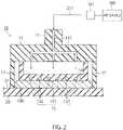
- FIG. 2is a sectional view of the polishing head 10 .
- the polishing head 10includes a support 11 , a retainer ring 12 , and a membrane 13 .
- the support 11supports the retainer ring 12 and the membrane 13 .
- a pipe 111is formed on the inside of the support 11 .
- Compressed air 211flows into the pipe 111 from an air source 200 .
- the pressure of the compressed air 211is adjusted by a valve 201 .
- the retainer ring 12is provided along the outer circumference of the substrate 100 under the support 11 .
- force for moving the substrate 100 to the outer side of the polishing head 10is generated.
- the substrate 100can be prevented from jumping out from the polishing head 10 by the retainer ring 12 .
- the membrane 13includes an elastic member 131 and air tubes 132 .
- the elastic member 131is, for example, rubber molded in a concave shape.
- the air tubes 132are provided in the elastic member 131 .
- FIG. 3is a plan view showing arrangement of the air tubes 132 .
- FIG. 4is a plan view showing other arrangement of the air tubes 132 .
- the air tubes 132may be arranged in a lattice pattern as shown in FIG. 3 or may be arranged in a radial pattern as shown in FIG. 4 .
- the polishing head 10 and the polishing pad 20rotate.
- the membrane 13is pressurized by the compressed air 211 supplied from the air source 200 through the pipe 111 .
- the membrane 13presses the substrate 100 against the polishing surface 21 of the polishing head 10 with applied pressure.
- a contact surface 14 of the membrane 13 that is in contact with the substrate 100 on the opposite side of the polishing surface 21is a flat surface as shown in FIG. 2 .
- the air tubes 132are not in contact with the substrate 100 .
- FIG. 5is a sectional view showing a state at the time when the substrate 100 is separated from the polishing head 10 .
- the substrate 100polishing ends, the substrate 100 is conveyed to a predetermined place apart from the polishing pad 20 .
- the air source 200feeds compressed air 212 into the air tubes 132 .
- the pressure of the compressed air 212is adjusted by a valve 202 .
- the air tubes 132expand with the pressure of the compressed air 212 . Consequently, the elastic member 131 is distorted. As a result, the contact surface 14 of the membrane 13 is deformed into an uneven surface as shown in FIG. 5 . On the uneven surface, the air tubes 132 form convex portions. However, the air tubes 132 are not in contact with the substrate 100 .
- the air tubes 132 provided in the membrane 13are expanded, whereby the shape of the contact surface 14 of the membrane 13 is deformed from the flat surface into the uneven surfaces.
- adhesion between the membrane 13 and the substrate 100decreases. Consequently, the substrate 100 easily separates from the membrane 13 .
- the air tubes 132are regularly arranged in the lattice pattern or the radial pattern. Accordingly, the uneven surface can be uniformly formed over the entire contact surface 14 . Further, since the air tubes 132 are not in contact with the substrate 100 , it is also possible to avoid damage to the substrate 100 .
- a polishing apparatus according to this embodimentis different from the polishing apparatus 1 according to the first embodiment in the configuration of a polishing head.
- FIG. 6is a sectional view of a polishing head 10 a according to the second embodiment.
- the same components as the components of the polishing head 10 according to the first embodiment explained aboveare denoted by the same reference numerals and signs. Detailed explanation of the components is omitted.
- the polishing head 10 aincludes a membrane 13 a .
- the membrane 13 aincludes the elastic member 131 and hard materials 133 having hardness higher than the hardness of the elastic member 131 .
- the elastic member 131is rubber molded in a concave shape as in the first embodiment.
- the hard materials 133are, for example, glass beads and provided in the elastic member 131 .
- FIG. 7is a plan view showing arrangement of the hard materials 133 .
- the hard materials 133are dotted in the elastic member 131 as shown in FIG. 7 .
- the hard materials 133may be glass fibers as shown in FIG. 8 .
- the polishing head 10 and the polishing pad 20rotate when the substrate 100 is polished.
- the membrane 13 apresses the substrate 100 against the polishing surface 21 of the polishing head 10 with the pressure of the compressed air 211 .
- the contact surface 14 of the membrane 13 ais a flat surface.
- the hard materials 133are not in contact with the substrate 100 .
- FIG. 9is a sectional view showing a state in which the substrate 100 is separated from the polishing head 10 a .
- the substrate 100polishing ends, the substrate 100 is conveyed to a predetermined place apart from the polishing pad 20 .
- the air source 200feeds compressed air 213 through the pipe 111 .
- the compressed air 213is adjusted by the valve 201 to pressure higher than the pressure of the compressed air 211 during the polishing.
- the elastic member 131 of the membrane 13 ais pulled in an in-plane direction parallel to the contact surface 14 and distorted by the pressure of the compressed air 213 .
- the hard materials 133are not deformed because the hard materials 133 have hardness higher than the hardness of the elastic member 131 .
- the contact surface 14 of the membrane 13 ais deformed into an uneven surface as shown in FIG. 9 .
- the hard materials 133form convex portions.
- the hard materials 133are not in contact with the substrate 100 .
- the contact surface 14 of the membrane 13 ais deformed into the uneven surface using the hard materials 133 contained in the elastic member 131 .
- adhesion between the membrane 13 a and the substrate 100decreases. Consequently, the substrate 100 easily separates from the membrane 13 a.
- the hard materials 133are not in contact with the substrate 100 , it is also possible to avoid damage to the substrate 100 .
- the elastic member 131is deformed with the pressure of the compressed air 212 .
- means for deforming the elastic member 131is not particularly limited if the uneven surface shown in FIG. 9 can be formed.
Landscapes
- Engineering & Computer Science (AREA)
- Mechanical Engineering (AREA)
- Finish Polishing, Edge Sharpening, And Grinding By Specific Grinding Devices (AREA)
- Mechanical Treatment Of Semiconductor (AREA)
Abstract
Description
Claims (4)
Applications Claiming Priority (3)
| Application Number | Priority Date | Filing Date | Title |
|---|---|---|---|
| JP2019-164572 | 2019-09-10 | ||
| JPJP2019-164572 | 2019-09-10 | ||
| JP2019164572AJP2021041485A (en) | 2019-09-10 | 2019-09-10 | Polishing equipment |
Publications (2)
| Publication Number | Publication Date |
|---|---|
| US20210069854A1 US20210069854A1 (en) | 2021-03-11 |
| US11517996B2true US11517996B2 (en) | 2022-12-06 |
Family
ID=74849489
Family Applications (1)
| Application Number | Title | Priority Date | Filing Date |
|---|---|---|---|
| US16/898,599Active2041-03-12US11517996B2 (en) | 2019-09-10 | 2020-06-11 | Polishing apparatus |
Country Status (2)
| Country | Link |
|---|---|
| US (1) | US11517996B2 (en) |
| JP (1) | JP2021041485A (en) |
Citations (13)
| Publication number | Priority date | Publication date | Assignee | Title |
|---|---|---|---|---|
| US6447368B1 (en)* | 2000-11-20 | 2002-09-10 | Speedfam-Ipec Corporation | Carriers with concentric balloons supporting a diaphragm |
| US20040142635A1 (en)* | 2003-01-16 | 2004-07-22 | Elledge Jason B. | Carrier assemblies, polishing machines including carrier assemblies, and methods for polishing micro-device workpieces |
| JP2005014128A (en) | 2003-06-24 | 2005-01-20 | Ebara Corp | Substrate holding device and polishing device |
| US20070167110A1 (en)* | 2006-01-16 | 2007-07-19 | Yu-Hsiang Tseng | Multi-zone carrier head for chemical mechanical polishing and cmp method thereof |
| US20150111477A1 (en)* | 2013-10-18 | 2015-04-23 | Taiwan Semiconductor Manufacturing Co., Ltd. | Polishing Head, Chemical-Mechanical Polishing System, and Method for Polishing Substrate |
| US9105516B2 (en) | 2012-07-03 | 2015-08-11 | Ebara Corporation | Polishing apparatus and polishing method |
| JP5891127B2 (en) | 2012-07-03 | 2016-03-22 | 株式会社荏原製作所 | Polishing apparatus and polishing method |
| JP2016072372A (en) | 2014-09-29 | 2016-05-09 | 株式会社荏原製作所 | Polishing device |
| US9539699B2 (en) | 2014-08-28 | 2017-01-10 | Ebara Corporation | Polishing method |
| US9662761B2 (en)* | 2013-12-02 | 2017-05-30 | Ebara Corporation | Polishing apparatus |
| JP2017185589A (en) | 2016-04-06 | 2017-10-12 | 株式会社荏原製作所 | Substrate processing equipment |
| JP2017190537A (en) | 2016-04-13 | 2017-10-19 | 国立研究開発法人産業技術総合研究所 | Sheet body with variable friction coefficient and friction coefficient varying apparatus |
| JP2018130772A (en) | 2017-02-13 | 2018-08-23 | 国立研究開発法人産業技術総合研究所 | Object holding member |
- 2019
- 2019-09-10JPJP2019164572Apatent/JP2021041485A/enactivePending
- 2020
- 2020-06-11USUS16/898,599patent/US11517996B2/enactiveActive
Patent Citations (16)
| Publication number | Priority date | Publication date | Assignee | Title |
|---|---|---|---|---|
| US6447368B1 (en)* | 2000-11-20 | 2002-09-10 | Speedfam-Ipec Corporation | Carriers with concentric balloons supporting a diaphragm |
| US20040142635A1 (en)* | 2003-01-16 | 2004-07-22 | Elledge Jason B. | Carrier assemblies, polishing machines including carrier assemblies, and methods for polishing micro-device workpieces |
| JP2005014128A (en) | 2003-06-24 | 2005-01-20 | Ebara Corp | Substrate holding device and polishing device |
| US7108592B2 (en) | 2003-06-24 | 2006-09-19 | Ebara Corporation | Substrate holding apparatus and polishing apparatus |
| JP4086722B2 (en) | 2003-06-24 | 2008-05-14 | 株式会社荏原製作所 | Substrate holding device and polishing device |
| US20070167110A1 (en)* | 2006-01-16 | 2007-07-19 | Yu-Hsiang Tseng | Multi-zone carrier head for chemical mechanical polishing and cmp method thereof |
| JP5891127B2 (en) | 2012-07-03 | 2016-03-22 | 株式会社荏原製作所 | Polishing apparatus and polishing method |
| US9105516B2 (en) | 2012-07-03 | 2015-08-11 | Ebara Corporation | Polishing apparatus and polishing method |
| US20150111477A1 (en)* | 2013-10-18 | 2015-04-23 | Taiwan Semiconductor Manufacturing Co., Ltd. | Polishing Head, Chemical-Mechanical Polishing System, and Method for Polishing Substrate |
| US9662761B2 (en)* | 2013-12-02 | 2017-05-30 | Ebara Corporation | Polishing apparatus |
| US9539699B2 (en) | 2014-08-28 | 2017-01-10 | Ebara Corporation | Polishing method |
| JP2016072372A (en) | 2014-09-29 | 2016-05-09 | 株式会社荏原製作所 | Polishing device |
| JP2017185589A (en) | 2016-04-06 | 2017-10-12 | 株式会社荏原製作所 | Substrate processing equipment |
| US20170291274A1 (en) | 2016-04-06 | 2017-10-12 | Ebara Corporation | Substrate processing apparatus |
| JP2017190537A (en) | 2016-04-13 | 2017-10-19 | 国立研究開発法人産業技術総合研究所 | Sheet body with variable friction coefficient and friction coefficient varying apparatus |
| JP2018130772A (en) | 2017-02-13 | 2018-08-23 | 国立研究開発法人産業技術総合研究所 | Object holding member |
Also Published As
| Publication number | Publication date |
|---|---|
| US20210069854A1 (en) | 2021-03-11 |
| JP2021041485A (en) | 2021-03-18 |
Similar Documents
| Publication | Publication Date | Title |
|---|---|---|
| JP7239539B2 (en) | Single-side polishing head with flexible center with recess and cap | |
| KR102467644B1 (en) | Polishing head, wafer polishing apparatus and polishing method using the same | |
| US7488240B2 (en) | Polishing device | |
| US8454413B2 (en) | Multi-chamber carrier head with a textured membrane | |
| CN101072658A (en) | Substrate holding device and polishing apparatus | |
| US11007619B2 (en) | Carrier head membrane with regions of different roughness | |
| JP7568808B2 (en) | CMP Equipment | |
| US10195716B2 (en) | Dresser, method of manufacturing dresser, and method of manufacturing semiconductor device | |
| US11517996B2 (en) | Polishing apparatus | |
| US7029383B2 (en) | Polishing head of chemical mechanical polishing apparatus | |
| JP2008173741A (en) | Polishing device | |
| JP7349791B2 (en) | CMP equipment | |
| KR100914604B1 (en) | Wafer Pressing Apparatus of a Polisher | |
| US12134162B2 (en) | Wafer polishing head, method for manufacturing wafer polishing head, and wafer polishing apparatus comprising same | |
| TW202319179A (en) | Elastic membrane and method of manufacturing elastic membrane | |
| TWI314763B (en) | Carrier head with flexible membrane | |
| US20120040591A1 (en) | Replaceable cover for membrane carrier | |
| CN216967413U (en) | Retainer ring and substrate grinding device comprising same | |
| KR20180129315A (en) | Membrane for carrier head | |
| KR20120108269A (en) | Head assembly and retainer ring for water grinding apparatus | |
| JP2009010227A (en) | Wafer deformation suppressing device and method for preventing deformation of wafer | |
| JP2005088171A (en) | Work holding head and polishing device having work holding head | |
| CN119923711A (en) | Carrier for polishing a workpiece having a plane or a void | |
| KR20220062814A (en) | Retainer ring and substrate polishing appratus comprising the same | |
| JP2018103304A (en) | Polishing equipment |
Legal Events
| Date | Code | Title | Description |
|---|---|---|---|
| AS | Assignment | Owner name:KIOXIA CORPORATION, JAPAN Free format text:ASSIGNMENT OF ASSIGNORS INTEREST;ASSIGNOR:TAKAGI, JUN;REEL/FRAME:052905/0946 Effective date:20200610 | |
| FEPP | Fee payment procedure | Free format text:ENTITY STATUS SET TO UNDISCOUNTED (ORIGINAL EVENT CODE: BIG.); ENTITY STATUS OF PATENT OWNER: LARGE ENTITY | |
| STPP | Information on status: patent application and granting procedure in general | Free format text:APPLICATION DISPATCHED FROM PREEXAM, NOT YET DOCKETED | |
| STPP | Information on status: patent application and granting procedure in general | Free format text:DOCKETED NEW CASE - READY FOR EXAMINATION | |
| STPP | Information on status: patent application and granting procedure in general | Free format text:NON FINAL ACTION MAILED | |
| STPP | Information on status: patent application and granting procedure in general | Free format text:RESPONSE TO NON-FINAL OFFICE ACTION ENTERED AND FORWARDED TO EXAMINER | |
| STPP | Information on status: patent application and granting procedure in general | Free format text:NOTICE OF ALLOWANCE MAILED -- APPLICATION RECEIVED IN OFFICE OF PUBLICATIONS | |
| STPP | Information on status: patent application and granting procedure in general | Free format text:PUBLICATIONS -- ISSUE FEE PAYMENT RECEIVED | |
| STPP | Information on status: patent application and granting procedure in general | Free format text:PUBLICATIONS -- ISSUE FEE PAYMENT VERIFIED | |
| STCF | Information on status: patent grant | Free format text:PATENTED CASE |