US11517775B2 - Respirator headband - Google Patents
Respirator headbandDownload PDFInfo
- Publication number
- US11517775B2 US11517775B2US15/523,419US201515523419AUS11517775B2US 11517775 B2US11517775 B2US 11517775B2US 201515523419 AUS201515523419 AUS 201515523419AUS 11517775 B2US11517775 B2US 11517775B2
- Authority
- US
- United States
- Prior art keywords
- headband
- main body
- protection device
- tab
- respiratory protection
- Prior art date
- Legal status (The legal status is an assumption and is not a legal conclusion. Google has not performed a legal analysis and makes no representation as to the accuracy of the status listed.)
- Active, expires
Links
- 230000000241respiratory effectEffects0.000claimsabstractdescription31
- 239000000835fiberSubstances0.000claimsdescription30
- 239000000463materialSubstances0.000claimsdescription27
- 239000000853adhesiveSubstances0.000claimsdescription15
- 230000001070adhesive effectEffects0.000claimsdescription15
- 229920001410MicrofiberPolymers0.000claimsdescription6
- 239000003658microfiberSubstances0.000claimsdescription6
- 238000003860storageMethods0.000claimsdescription3
- 238000000034methodMethods0.000description8
- 238000001914filtrationMethods0.000description7
- -1polypropylenePolymers0.000description6
- 230000002093peripheral effectEffects0.000description5
- 230000008901benefitEffects0.000description4
- 239000002245particleSubstances0.000description4
- 239000011230binding agentSubstances0.000description3
- 239000011521glassSubstances0.000description3
- 230000008569processEffects0.000description3
- 238000007493shaping processMethods0.000description3
- OKTJSMMVPCPJKN-UHFFFAOYSA-NCarbonChemical compound[C]OKTJSMMVPCPJKN-UHFFFAOYSA-N0.000description2
- 239000004698PolyethyleneSubstances0.000description2
- 239000000428dustSubstances0.000description2
- 238000010438heat treatmentMethods0.000description2
- 239000012943hotmeltSubstances0.000description2
- 238000004519manufacturing processMethods0.000description2
- 229920000728polyesterPolymers0.000description2
- 229920000573polyethylenePolymers0.000description2
- 229920000098polyolefinPolymers0.000description2
- 239000004834spray adhesiveSubstances0.000description2
- 238000003466weldingMethods0.000description2
- NLHHRLWOUZZQLW-UHFFFAOYSA-NAcrylonitrileChemical groupC=CC#NNLHHRLWOUZZQLW-UHFFFAOYSA-N0.000description1
- 239000004743PolypropyleneSubstances0.000description1
- BZHJMEDXRYGGRV-UHFFFAOYSA-NVinyl chlorideChemical groupClC=CBZHJMEDXRYGGRV-UHFFFAOYSA-N0.000description1
- NIXOWILDQLNWCW-UHFFFAOYSA-Nacrylic acid groupChemical groupC(C=C)(=O)ONIXOWILDQLNWCW-UHFFFAOYSA-N0.000description1
- 238000004026adhesive bondingMethods0.000description1
- 239000004840adhesive resinSubstances0.000description1
- 229920006223adhesive resinPolymers0.000description1
- PNEYBMLMFCGWSK-UHFFFAOYSA-Naluminium oxideInorganic materials[O-2].[O-2].[O-2].[Al+3].[Al+3]PNEYBMLMFCGWSK-UHFFFAOYSA-N0.000description1
- 238000013459approachMethods0.000description1
- 230000004888barrier functionEffects0.000description1
- 238000005266castingMethods0.000description1
- 229920002678cellulosePolymers0.000description1
- 239000001913celluloseSubstances0.000description1
- 238000010276constructionMethods0.000description1
- 238000007796conventional methodMethods0.000description1
- 238000001816coolingMethods0.000description1
- 239000007789gasSubstances0.000description1
- 229910052736halogenInorganic materials0.000description1
- 125000005843halogen groupChemical group0.000description1
- 230000006872improvementEffects0.000description1
- 238000002955isolationMethods0.000description1
- 238000005304joiningMethods0.000description1
- 239000004816latexSubstances0.000description1
- 229920000126latexPolymers0.000description1
- 230000007246mechanismEffects0.000description1
- 238000002844meltingMethods0.000description1
- 230000008018meltingEffects0.000description1
- 239000002184metalSubstances0.000description1
- 239000000203mixtureSubstances0.000description1
- 230000001473noxious effectEffects0.000description1
- 239000011236particulate materialSubstances0.000description1
- 229920001748polybutylenePolymers0.000description1
- 229920000515polycarbonatePolymers0.000description1
- 239000004417polycarbonateSubstances0.000description1
- 229920000306polymethylpentenePolymers0.000description1
- 239000011116polymethylpenteneSubstances0.000description1
- 229920001155polypropylenePolymers0.000description1
- 239000004814polyurethaneSubstances0.000description1
- 229920002635polyurethanePolymers0.000description1
- 230000002028prematureEffects0.000description1
- 210000002345respiratory systemAnatomy0.000description1
- 238000000926separation methodMethods0.000description1
- 238000009958sewingMethods0.000description1
- 239000002594sorbentSubstances0.000description1
- BFKJFAAPBSQJPD-UHFFFAOYSA-NtetrafluoroetheneChemical groupFC(F)=C(F)FBFKJFAAPBSQJPD-UHFFFAOYSA-N0.000description1
- 230000000930thermomechanical effectEffects0.000description1
- 229920001169thermoplasticPolymers0.000description1
- 239000004416thermosoftening plasticSubstances0.000description1
- 239000012780transparent materialSubstances0.000description1
- 238000010792warmingMethods0.000description1
- 239000002699waste materialSubstances0.000description1
Images


Classifications
- A—HUMAN NECESSITIES
- A41—WEARING APPAREL
- A41D—OUTERWEAR; PROTECTIVE GARMENTS; ACCESSORIES
- A41D13/00—Professional, industrial or sporting protective garments, e.g. surgeons' gowns or garments protecting against blows or punches
- A41D13/05—Professional, industrial or sporting protective garments, e.g. surgeons' gowns or garments protecting against blows or punches protecting only a particular body part
- A41D13/11—Protective face masks, e.g. for surgical use, or for use in foul atmospheres
- A41D13/1161—Means for fastening to the user's head
- A—HUMAN NECESSITIES
- A62—LIFE-SAVING; FIRE-FIGHTING
- A62B—DEVICES, APPARATUS OR METHODS FOR LIFE-SAVING
- A62B23/00—Filters for breathing-protection purposes
- A62B23/02—Filters for breathing-protection purposes for respirators
- A62B23/025—Filters for breathing-protection purposes for respirators the filter having substantially the shape of a mask
- A—HUMAN NECESSITIES
- A41—WEARING APPAREL
- A41D—OUTERWEAR; PROTECTIVE GARMENTS; ACCESSORIES
- A41D13/00—Professional, industrial or sporting protective garments, e.g. surgeons' gowns or garments protecting against blows or punches
- A41D13/05—Professional, industrial or sporting protective garments, e.g. surgeons' gowns or garments protecting against blows or punches protecting only a particular body part
- A41D13/11—Protective face masks, e.g. for surgical use, or for use in foul atmospheres
- A41D13/1107—Protective face masks, e.g. for surgical use, or for use in foul atmospheres characterised by their shape
- A41D13/1138—Protective face masks, e.g. for surgical use, or for use in foul atmospheres characterised by their shape with a cup configuration
- A—HUMAN NECESSITIES
- A62—LIFE-SAVING; FIRE-FIGHTING
- A62B—DEVICES, APPARATUS OR METHODS FOR LIFE-SAVING
- A62B18/00—Breathing masks or helmets, e.g. affording protection against chemical agents or for use at high altitudes or incorporating a pump or compressor for reducing the inhalation effort
- A62B18/02—Masks
- A62B18/025—Halfmasks
- A—HUMAN NECESSITIES
- A62—LIFE-SAVING; FIRE-FIGHTING
- A62B—DEVICES, APPARATUS OR METHODS FOR LIFE-SAVING
- A62B7/00—Respiratory apparatus
- A62B7/10—Respiratory apparatus with filter elements
- A—HUMAN NECESSITIES
- A62—LIFE-SAVING; FIRE-FIGHTING
- A62B—DEVICES, APPARATUS OR METHODS FOR LIFE-SAVING
- A62B9/00—Component parts for respiratory or breathing apparatus
- A—HUMAN NECESSITIES
- A41—WEARING APPAREL
- A41D—OUTERWEAR; PROTECTIVE GARMENTS; ACCESSORIES
- A41D2400/00—Functions or special features of garments
- A41D2400/44—Donning facilities
- A—HUMAN NECESSITIES
- A41—WEARING APPAREL
- A41D—OUTERWEAR; PROTECTIVE GARMENTS; ACCESSORIES
- A41D2400/00—Functions or special features of garments
- A41D2400/70—Removability
Definitions
- the present inventionrelates to personal respiratory protection devices, known as respirators or face masks, which are capable of being folded flat during storage and forming a cup-shaped air chamber over the mouth and nose of a wearer during use.
- Filtration respirators or face masksare used in a wide variety of applications when it is desired to protect a human's respiratory system from particles suspended in the air or from unpleasant or noxious gases.
- respirators or face masksmay come in a number of forms but two of the most common are a molded cup-shaped form or a flat-folded form.
- the flat-folded formhas advantages in that it can be carried in a wearer's pocket until needed and re-folded flat to keep the inside clean between wearings.
- Such respiratory devicesinclude, for example, respirators, surgical masks, clean room masks, face shields, dust masks, breath warming masks, and a variety of other face coverings.
- Flat-fold respiratorsare typically formed from a sheet filter medium which is folded or joined to form two or more panels.
- the panelsare opened out prior to or during the donning process to form the air chamber.
- an exhalation valveis provided on one of the panels in order to reduce the respiratory effort of exhaling.
- the respiratorprefferably includes a headband for holding the respirator in position on the head of the user.
- the headbandmay be formed in one piece or, more commonly, in two or more sections. Headbands are formed from a wide range of materials which demonstrate elastic properties. However, all headbands, irrespective of the material from which they are formed, must be fixed to main body of the respirator.
- a personal respiratory protection devicecomprising:
- a main bodyhaving a headband attachment portion
- a headbandattached to the headband attachment portion by a headband bond module
- the moduleincludes first and second non-woven tabs adhesively bonded to opposing sides of an end of the headband
- the side of the first tab opposing the headband bond sidebeing welded to the main body.
- this construction of headband attachmentallows the adhesive bond to be effectively deployed in joining the headband to the non-woven tab on the main body. Furthermore it ensures that the adhesive bond operates substantially in shear rather than peel, thus maximizing the mechanical characteristics of the adhesive bond. Conversely, the weld bond is effectively deployed in welding the non-woven main body to the non-woven tabs. This ensures that the welded bonds are in peel, not the adhesive bonds. This is advantageous since the welded bonds perform considerably better in peel conditions than does the adhesive bond.
- the resultis a strong joint between the headband and the main body that maximizes the advantages of each type of bond in order to reduce the cost of manufacture of the respirator and reduce the in-service failure rate.
- the main bodycomprises:
- the central panelbeing separated from each of the upper and lower panels by a first and second fold, seam, weld or bond, respectively, such that device is capable of being folded flat for storage along the first and second fold, seam, weld or bond and opened to form a cup-shaped air chamber over the nose and mouth of the wearer when in use,
- the devicehas an attachment portion at each side of the main body to attach each end of the headband to the main body.
- the adhesive bondsare in shear when the device is in use in its open configuration.
- the weld between the first tab and the main bodyis an ultrasonic weld.
- the weldis in peel when the device is in use in its open configuration.
- FIG. 1is a front view of a personal respiratory protection device of the current invention in its flat-fold configuration
- FIG. 2is a rear view of the personal respiratory protection device of FIG. 1 in its flat-fold configuration
- FIG. 3is a cross-section of the personal respiratory protection device shown in FIG. 1 taken along line III-III in FIG. 2 ;
- FIG. 4is a front view of the personal respiratory protection device of FIG. 1 shown in its open configuration
- FIG. 5is a side view of the personal respiratory protection device of FIG. 1 shown in open ready-to-use configuration
- FIG. 6is a rear view of the personal respiratory protection device of FIG. 1 shown in its open configuration
- FIG. 7is a cross-sectional view of the personal respiratory protection device of FIG. 1 shown in its intermediate configuration with the open configuration non-cross-sectioned side view shown in dotted lines;
- FIG. 8is a detailed top perspective view of the stiffening panel of the respirator of FIG. 1 ;
- FIG. 9is a front perspective view of the personal respiratory protection device of FIG. 1 shown in its open configuration on the face of a user and being held by a user;
- FIG. 10is a detailed front perspective view of the valve of the personal respiratory protection device of FIG. 1 ;
- FIG. 11is a detailed front perspective view of an alternative embodiment of the valve of the personal respiratory protection device of FIG. 1 ;
- FIG. 12is a detailed cross-sectional view of part of the personal respiratory protection device of FIG. 1 taken along line XI-XI in FIG. 2 and showing attachment of the headband to the main body with the device in its flat-fold configuration;
- FIG. 13is a detailed cross-sectional view of part of the personal respiratory protection device of FIG. 1 taken similar to FIG. 12 and showing attachment of the headband to the main body with the device in its open configuration, and
- FIG. 14is a detailed front perspective view of the nosepiece of the personal respiratory protection device of FIG. 1 .
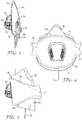
- FIG. 1shows a personal respiratory protection device in the form of a respirator (also commonly referred to as a mask) indicated generally at 10 .
- the respirator 10is a flat-fold respirator which is shown in FIGS. 1 to 3 in its stored (also known as flat-fold or flat-folded) configuration. In this configuration the respirator is substantially flat so that it may be readily stored in the pocket of a user.
- the respirator 10has a main body indicated generally at 12 and a headband 14 formed of two sections 14 A, 14 B.
- the main body 12has a central panel 16 , an upper panel 18 and a lower panel 20 .
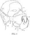
- the upper panel 18 and lower panel 20are opened outwardly from the central panel 16 to form a cup-shaped chamber 22 (shown in FIG. 6 ). Once opened, the respirator is then applied to the face (as shown in FIG. 9 ) as will be described in further detail shortly.
- the respirator 10is formed from folded and welded portions of multi-layered filter material to form three portions or panels, as will be discussed in further detail below.
- the respirator 10has a multi-layered structure that comprises a first inner cover web, a filtration layer that comprises a web that contains electrically-charged microfibers, and a second outer cover web, the first and second cover webs being disposed on first and second opposing sides of the filtration layer, respectively.
- the filter materialmay be comprised of a number of woven and nonwoven materials, a single or a plurality of layers, with or without an inner or outer cover or scrim.
- the central panel 16is provided with stiffening means such as, for example, woven or nonwoven scrim, adhesive bars, printing or bonding.
- suitable filter materialinclude microfiber webs, fibrillated film webs, woven or nonwoven webs (e.g., airlaid or carded staple fibers), solution-blown fiber webs, or combinations thereof.
- Fibers useful for forming such websinclude, for example, polyolefins such as polypropylene, polyethylene, polybutylene, poly(4-methyl-1-pentene) and blends thereof, halogen substituted polyolefins such as those containing one or more chloroethylene units, or tetrafluoroethylene units, and which may also contain acrylonitrile units, polyesters, polycarbonates, polyurethanes, rosin-wool, glass, cellulose or combinations thereof.
- polyolefinssuch as polypropylene, polyethylene, polybutylene, poly(4-methyl-1-pentene) and blends thereof
- halogen substituted polyolefinssuch as those containing one or more chloroethylene units, or tetrafluoroethylene units, and which may also contain acrylonitrile units
- polyesterspolycarbonates, polyurethanes, rosin-wool, glass, cellulose or combinations thereof.
- Fibers of the filtering layerare selected depending upon the type of particulate to be filtered. Proper selection of fibers can also affect the comfort of the respiratory device to the wearer, e.g., by providing softness or moisture control.
- Webs of melt blown microfibers useful in the present inventioncan be prepared as described, for example, in Wente, Van A., “Superfine Thermoplastic Fibers” in Industrial Engineering Chemistry, Vol. 48, 1342 et seq. (1956) and in Report No. 4364 of the Navel Research Laboratories, published May 25, 1954, entitled “Manufacture of Super Fine Organic Fibers” by Van A. Wente et al.
- the blown microfibers in the filter media useful on the present inventionpreferably have an effective fiber diameter of from 3 to 30 micrometers, more preferably from about 7 to 15 micrometers, as calculated according to the method set forth in Davies, C. N., “The Separation of Airborne Dust Particles”, Institution of Mechanical Engineers, London, Proceedings 1B, 1952.
- Staple fibersmay also, optionally, be present in the filtering layer.
- the presence of crimped, bulking staple fibersprovides for a more lofty, less dense web than a web consisting solely of blown microfibers.
- no more than 90 weight percent staple fibers, more preferably no more than 70 weight percentare present in the media.
- Such webs containing staple fiberare disclosed in U.S. Pat. No. 4,118,531 (Hauser).
- Bicomponent staple fibersmay also be used in the filtering layer or in one or more other layers of the filter media.
- the bicomponent staple fiberswhich generally have an outer layer which has a lower melting point than the core portion can be used to form a resilient shaping layer bonded together at fiber intersection points, e.g., by heating the layer so that the outer layer of the bicomponent fibers flows into contact with adjacent fibers that are either bicomponent or other staple fibers.
- the shaping layercan also be prepared with binder fibers of a heat-flowable polyester included together with staple fibers and upon heating of the shaping layer the binder fibers melt and flow to a fiber intersection point where they surround the fiber intersection point. Upon cooling, bonds develop at the intersection points of the fibers and hold the fiber mass in the desired shape.
- binder materialssuch as acrylic latex or powdered heat actuable adhesive resins can be applied to the webs to provide bonding of the fibers.
- Electrically charged fiberssuch as are disclosed in U.S. Pat. No. 4,215,682 (Kubik et al.), U.S. Pat. No. 4,588,537 (Klasse et al.) or by other conventional methods of polarizing or charging electrets, e.g., by the process of U.S. Pat. No. 4,375,718 (Wadsworth et al.), or U.S. Pat. No. 4,592,815 (Nakao), are particularly useful in the present invention. Electrically charged fibrillated-film fibers as taught in U.S. Pat. No. RE. 31,285 (van Turnhout), are also useful. In general the charging process involves subjecting the material to corona discharge or pulsed high voltage.
- Sorbent particulate materialsuch as activated carbon or alumina may also be included in the filtering layer.
- Sorbent particulate materialsuch as activated carbon or alumina may also be included in the filtering layer.
- Such particle-loaded websare described, for example, in U.S. Pat. No. 3,971,373 (Braun), U.S. Pat. No. 4,100,324 (Anderson) and U.S. Pat. No. 4,429,001 (Kolpin et al.). Masks from particle loaded filter layers are particularly good for protection from gaseous materials.
- At least one of the central panel 16 , upper panel 18 and lower panel 20 of the respiratory device of the present inventionmust comprise filter media.
- the portion(s) not formed of filter mediamay be formed of a variety of materials.
- the upper panel 18may be formed, for example, from a material which provides a moisture barrier to prevent fogging of a wearer's glasses.
- the central panel 16may be formed of a transparent material so that lip movement by the wearer can be observed.
- the central panel 16has a curvilinear upper peripheral edge 24 which is coexistent with an upper bond 23 between the central panel 16 and the upper portion 18 .
- a curvilinear lower peripheral edge 26is coexistent with a lower bond 25 between the central panel 16 and the lower panel 20 .
- the bonds 23 , 25take the form of ultrasonic welds but may alternatively be folds in the filter material or alternative methods of bonding. Such alternative bonds may take the form of adhesive bonding, stapling, sewing, thermomechanical connection, pressure connection, or other suitable means and can be intermittent or continuous. Any of these welding or bonding techniques leaves the bonded area somewhat strengthened or rigidified.
- the bonds 23 , 25form a substantially airtight seal between the central panel 16 and the upper and lower panels 18 , 20 , respectively and extend to the longitudinal edges 27 of the respirator where the central upper, lower panels 16 , 18 , 20 collectively form headband attachment portions in the form of lugs 31 , 33 .
- the central panel 16carries an exhalation valve 28 which reduces the pressure drop across the filter material when the user exhales.
- the valve 28has grip portions 29 which ease the opening, donning and doffing of the respirator as will be described in further detail below.
- the upper portion 18carries a nose conforming element in the form of nosepiece 30 which conforms to the face of the user to improve the seal formed between the respirator 10 and the face of the user.
- the nosepiece 30is arranged centrally at the upper outer periphery 38 of the upper portion 18 and is shown in section in FIG. 3 and in greater detail in FIG. 14 .
- the nosepieceoperates in conjunction with a nose pad 35 which is shown in FIG. 7 to be located on the opposite side of the upper panel 18 to the nosepiece 30 and serves the propose of softening the point of contact between the nose and the upper panel 18 .
- FIG. 3the arrangement of the features of the respirator 10 in its stored configuration is shown in greater detail.
- the nosepiece 30is shown positioned on the outer surface of the upper portion 18 .
- the upper portion 18is shown at the rearward side of the folded respirator 10 overlapping the lower panel 20 .
- the lower panel 20is folded about a lateral fold 36 (shown as a long dotted line in FIG. 2 ).
- the lateral fold 36divides the lower panel 20 into an outer section 40 and an inner section 42 .
- Attached to the lower panel 20is a tab 32 which assists in the opening and donning of the respirator as will be described in further detail below.
- the tab 32has a base which is attached to an interior portion of the exterior surface lower panel 20 (that is to say inwardly of a lower outer periphery 50 (as shown in FIG. 6 ) and the lower bond 25 ) at a position proximate the lateral fold 36 and ideally attached at the fold 36 as shown in FIG. 3 .
- the positioning of the tab 32may vary within 10 mm either side of the lateral fold.
- the width of the tab 32 at its point of attachment to the lower panel 20is 15 mm although this width may vary between 10 mm and 40 mm.
- FIGS. 4 , 5 and 6show the respirator 10 in its open configuration.
- the central panel 16is no longer flat as shown in FIGS. 1 to 3 but is now curved rearwardly from the valve 28 to the lugs 31 , 33 .
- the shape of this curveapproximately conforms to the mouth area of the face of the user.
- the upper portion 18is pivoted about the curvilinear upper peripheral edge 24 and is curved to form a peak which matches the shape of the nose of the user.
- the lower panel 20is pivoted about the curvilinear lower peripheral edge 24 to form a curve which matches the shape of the neck of the user.
- FIG. 7shows a cross-section of the respirator 10 sectioned along the same line as FIG. 3 but with the respirator shown in an intermediate configuration. Dotted lines show the respirator in the open configuration for comparison.
- the userTo open and don the respirator, the user first grips the grip portions 29 of the valve 28 (see FIG. 9 ). With the other hand the user takes hold of the tab 32 and pulls the tab 32 in direction A as indicated in FIG. 7 in order to apply an opening force to the valley side of the lateral fold 36 .
- the tabmay be textured to improve grip or may be coloured to better distinguish from the main body of the respirator.
- This opening forcecauses the fold 36 to move rearwardly and downwardly with respect to the central panel 16 . This causes the lower panel 20 to pivot about the curvilinear lower peripheral edge 24 . Simultaneously, load is transferred from the base of the tab 32 to the lugs 31 , 33 .
- the tab 32improves the opening mechanism of the respirator by ensuring that the load applied by the user to open the respirator 10 is most effectively and efficiently deployed to open the respirator 10 .
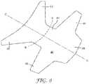
- the lower panel 20is shown to include a stiffening sheet in the form of panel 40 (shown in long dotted lines).
- the stiffening panel 40forms part of the multilayered filter material and is formed from material well known in the art for its stiffening properties.
- the stiffening panel 40is approximately hour-glass shaped and is shown in greater detail in FIG. 8 to include a first pair of wings 42 , a waist portion 44 , a second pair of wings 46 and a front section 48 .
- the front section 48is coexistent with the lower outer periphery 50 (as shown in FIG. 6 ) of the lower panel 20 and the waist section is coexistent with the lateral fold 36 .
- the stiffening panel 40When the respirator 10 is in its folded configuration, the stiffening panel 40 is folded along al lateral crease indicated at line B-B. As the respirator 10 opens from the folded position as described above, the stiffening panel 40 opens out about lateral crease line B-B. As the respirator approaches the open configuration (as shown in FIGS. 4 to 6 ) the fold along lateral crease line B-B flattens out and the stiffening panel curves about a longitudinal crease indicated at line C-C. The curving of the panel 40 along longitudinal crease line C-C prevents the folding about lateral crease line B-B which gives the stiffening panel 40 and thereby lower panel 20 additional rigidity.
- This additional rigidityis at least in part imparted by the stiffening sheet 40 folding about longitudinal crease line C-C as the respirator 10 opens from a concave external angle to a convex external angle, that is to say a mountain fold is formed when the fold goes overcentre about the longitudinal crease line C-C. This in turn helps to prevent the collapse of the lower panel 20 and thus improves the conformity of the lower panel 20 to the chin area of the face.
- the useris able to position the open cup-shaped air chamber of the respirator over the face and position the headbands as shown in FIG. 9 in order to don the respirator.
- the respiratoris provided with a valve 28 with grip portions 29 which are shown in greater detail in FIG. 10 .
- the valve 28is adhered to the central portion using an adhesive such as that commercially available under the trade designation 3MTM Scotch-WeldTM Hot Melt Spray Adhesive 61113MTM.
- the valve 28has side walls 51 which include apertures 52 to allow the exhaled air to pass through the valve 28 .
- the side walls 51have a curved form with an inwardly extending mid-portion and outwardly extending base 54 and upper section 56 .
- Arranged on a top surface 58 of the valve 28are upwardly extending ridges 60 which carry outwardly extending ribs 62 .
- the curved side walls 51act as a grip region 29 since the curves match the curvature of the fingers of the user.
- the performance of the grip regionis improved by the provision of the ridges 60 which extends the grip region. Performance is further improved by the provision of the ribs 62 which make the grip region 29 easier to grip and hold.
- the curved side walls 51 , ridges 60 ribs 62individually and collectively form an indicia to the user that the grip region 29 is to be gripped in order to open and don the respirator as described above.
- FIG. 10shows an alternative embodiment of valve 28 ′ which differs from valve 28 in that it has taller ridges 60 ′. It is conceivable within the scope of the invention that other forms of grip region could act as indicia to the user, for example a textured or colored surface to the side walls 50 , ridges 60 and/or ribs 62 .
- valve 28 , 28 ′could be equally applied to other respirators including cup respirators.
- the headband 14is attached to the main body 12 by a head band module indicated generally at 70 .
- the module 70has a headband 14 which is bonded on its upper side to an upper tab 72 and on its lower side to a lower tab 74 .
- the tabs 72 , 74are formed of a non-woven material used to form the filter material described above.
- the non-woven material tabs 72 , 74are bonded to the headband 14 using a known adhesive 78 such as that commercially available under the trade designation 3MTM Scotch-WeldTM Hot Melt Spray Adhesive 6111.
- the module 70is then ultrasonically welded to the lug 31 , 33 to form a weld 76 between the lower tab 74 and the main body 12 .
- FIG. 11the head band module is shown with the respirator in its folded position. As the respirator 10 is opened the headband becomes stretched and pulls outwardly on the lugs 31 , 33 .
- the head band moduleis shown with the respirator in its open position.
- the stretching of the headband 14causes the module 70 to curve which leads to the lower tab 74 being held in tension. This causes a high load to act at the point of intersection D of the lower tab 74 and the lug 31 , 33 .
- the weld 76is relatively strong in peel mode (that is to say the extreme tension load applied to the edge of the weld at point D by the stretching of the headband). This provides an improvement over prior art attachment techniques which place an adhesive bond in peel mode rather than a weld which is far stronger in peel than an adhesive.
- the nosepiece 30is shown in greater detail to have a resiliently flexible central portion 80 and first and second rigid outer portions 82 extending outwardly from the central portion 80 .
- the central portion 80is substantially flat when the respirator is in the flat fold configuration.
- the central portion 80is approximately 20 mm wide and 8 mm deep.
- Each of the outer portions 80has a wing which defines a concave elliptical bowl having an outwardly extending major axis X and upwardly extending minor axis Z.
- Each elliptical bowlhas a nadir indicated generally at 84 and positioned approximately equidistant between a centerline of the nosepiece 30 and an outer edge 86 of the wings, the nadir being positioned 26 mm from the centerline of the nosepiece 30 .
- the elliptical bowlgives the outer portions 82 rigidity whilst the flat central portion 80 is able to flex under load. This allows the central portion 80 to flex over the bridge of the nose of the user whilst the rigidity of the outer portions 82 and the varying point of contact offered by the curved profile of the rigid portions offers a close fit between the respirator and the cheek of the user.
- the nosepiece 30is formed using a known vacuum casting technique using a polymeric material such as polyethylene. Such a material gives the required flexibility in the central portion 80 whilst having sufficient strength to give the outer portions 82 the required rigidity. Such a material also allows the nosepiece to return to its flat position which allows the respirator 10 to be removed and placed in the pocket of the user without the requirement to flatten the nosepiece.
- a polymeric materialsuch as polyethylene.
Landscapes
- Health & Medical Sciences (AREA)
- General Health & Medical Sciences (AREA)
- Physical Education & Sports Medicine (AREA)
- Engineering & Computer Science (AREA)
- Textile Engineering (AREA)
- Business, Economics & Management (AREA)
- Emergency Management (AREA)
- Pulmonology (AREA)
- Life Sciences & Earth Sciences (AREA)
- Zoology (AREA)
- Respiratory Apparatuses And Protective Means (AREA)
Abstract
Description
Claims (10)
Applications Claiming Priority (4)
| Application Number | Priority Date | Filing Date | Title |
|---|---|---|---|
| GB1421616.2 | 2014-12-04 | ||
| GB1421616 | 2014-12-04 | ||
| GBGB1421616.2AGB201421616D0 (en) | 2014-12-04 | 2014-12-04 | Respirator headband |
| PCT/US2015/063316WO2016089937A1 (en) | 2014-12-04 | 2015-12-02 | Respirator headband |
Publications (2)
| Publication Number | Publication Date |
|---|---|
| US20180272161A1 US20180272161A1 (en) | 2018-09-27 |
| US11517775B2true US11517775B2 (en) | 2022-12-06 |
Family
ID=52425477
Family Applications (1)
| Application Number | Title | Priority Date | Filing Date |
|---|---|---|---|
| US15/523,419Active2036-06-20US11517775B2 (en) | 2014-12-04 | 2015-12-05 | Respirator headband |
Country Status (10)
| Country | Link |
|---|---|
| US (1) | US11517775B2 (en) |
| EP (1) | EP3226708B1 (en) |
| JP (1) | JP6382449B2 (en) |
| KR (1) | KR101892408B1 (en) |
| BR (1) | BR112017011431A2 (en) |
| CA (1) | CA2969395A1 (en) |
| GB (1) | GB201421616D0 (en) |
| RU (1) | RU2666464C1 (en) |
| SG (1) | SG11201704405QA (en) |
| WO (1) | WO2016089937A1 (en) |
Families Citing this family (10)
| Publication number | Priority date | Publication date | Assignee | Title |
|---|---|---|---|---|
| US9770611B2 (en) | 2007-05-03 | 2017-09-26 | 3M Innovative Properties Company | Maintenance-free anti-fog respirator |
| US20080271739A1 (en) | 2007-05-03 | 2008-11-06 | 3M Innovative Properties Company | Maintenance-free respirator that has concave portions on opposing sides of mask top section |
| GB201508114D0 (en) | 2015-05-12 | 2015-06-24 | 3M Innovative Properties Co | Respirator tab |
| USD900306S1 (en)* | 2016-09-16 | 2020-10-27 | 3M Innovative Properties Company | Valve cover |
| WO2019012399A1 (en) | 2017-07-14 | 2019-01-17 | 3M Innovative Properties Company | Adapter for conveying plural liquid streams |
| USD914216S1 (en)* | 2018-06-29 | 2021-03-23 | 3M Innovative Properties Company | Nose tab |
| KR102449927B1 (en)* | 2019-10-28 | 2022-09-29 | 이상호 | Horizontally flat-foldable 3-panel mask |
| KR102551152B1 (en)* | 2020-01-21 | 2023-07-05 | (주)피앤티디 | Mask |
| US11206880B1 (en)* | 2020-07-17 | 2021-12-28 | Pegasos One, LLC | Face shield for personal protection |
| US20230292858A1 (en)* | 2022-03-18 | 2023-09-21 | Katharos Laboratories, Llc | Face mask with tension adjusters and integral head strap |
Citations (34)
| Publication number | Priority date | Publication date | Assignee | Title |
|---|---|---|---|---|
| US3082767A (en)* | 1961-05-05 | 1963-03-26 | Welsh Mfg Co | Head straps for respirator |
| US3971373A (en) | 1974-01-21 | 1976-07-27 | Minnesota Mining And Manufacturing Company | Particle-loaded microfiber sheet product and respirators made therefrom |
| US4100324A (en) | 1974-03-26 | 1978-07-11 | Kimberly-Clark Corporation | Nonwoven fabric and method of producing same |
| US4118531A (en) | 1976-08-02 | 1978-10-03 | Minnesota Mining And Manufacturing Company | Web of blended microfibers and crimped bulking fibers |
| US4215682A (en) | 1978-02-06 | 1980-08-05 | Minnesota Mining And Manufacturing Company | Melt-blown fibrous electrets |
| US4375718A (en) | 1981-03-12 | 1983-03-08 | Surgikos, Inc. | Method of making fibrous electrets |
| USRE31285E (en) | 1976-12-23 | 1983-06-21 | Minnesota Mining And Manufacturing Company | Method for manufacturing a filter of electrically charged electret fiber material and electret filters obtained according to said method |
| US4419994A (en)* | 1980-07-03 | 1983-12-13 | Racal Safety Limited | Respirators |
| US4429001A (en) | 1982-03-04 | 1984-01-31 | Minnesota Mining And Manufacturing Company | Sheet product containing sorbent particulate material |
| US4588537A (en) | 1983-02-04 | 1986-05-13 | Minnesota Mining And Manufacturing Company | Method for manufacturing an electret filter medium |
| US4592815A (en) | 1984-02-10 | 1986-06-03 | Japan Vilene Co., Ltd. | Method of manufacturing an electret filter |
| US4635628A (en) | 1985-09-11 | 1987-01-13 | Tecnol, Inc. | Surgical face mask with improved moisture barrier |
| US5724677A (en)* | 1996-03-08 | 1998-03-10 | Minnesota Mining And Manufacturing Company | Multi-part headband and respirator mask assembly and process for making same |
| US6102039A (en) | 1997-12-01 | 2000-08-15 | 3M Innovative Properties Company | Molded respirator containing sorbent particles |
| US6125849A (en) | 1997-11-11 | 2000-10-03 | 3M Innovative Properties Company | Respiratory masks having valves and other components attached to the mask by a printed patch of adhesive |
| WO2001030449A1 (en) | 1999-10-22 | 2001-05-03 | 3M Innovative Properties Company | Retention assembly with compression element and method of use |
| WO2001058293A1 (en) | 2000-02-09 | 2001-08-16 | 3M Innovative Properties Company | Filtering face mask that has headband mounts |
| US6332465B1 (en) | 1999-06-02 | 2001-12-25 | 3M Innovative Properties Company | Face masks having an elastic and polyolefin thermoplastic band attached thereto by heat and pressure |
| US6978782B2 (en) | 2002-08-27 | 2005-12-27 | Amad Tayebi | Full face mask |
| US20080271740A1 (en) | 2007-05-03 | 2008-11-06 | 3M Innovative Properties Company | Maintenance-free flat-fold respirator that includes a graspable tab |
| US20080271737A1 (en) | 2007-05-03 | 2008-11-06 | 3M Innovative Properties Company | Maintenance-free anti-fog respirator |
| US20090044812A1 (en)* | 2007-08-16 | 2009-02-19 | Welchel Debra N | Strap fastening system for a disposable respirator providing improved donning |
| US20090044809A1 (en) | 2007-08-16 | 2009-02-19 | Kimberly-Clark Worldwide, Inc. | Vent and strap fastening system for a disposable respirator |
| US20090235934A1 (en) | 2008-03-24 | 2009-09-24 | 3M Innovative Properties Company | Filtering face-piece respirator having an integrally-joined exhalation valve |
| US20100031962A1 (en)* | 2006-03-24 | 2010-02-11 | Chun-Liang Chiu | Detachable Disposable Mask and a Disposable Mask Body Thereof |
| US20100154805A1 (en) | 2008-12-18 | 2010-06-24 | 3M Innovative Properties Company | Flat fold respirator having flanges disposed on the mask body |
| US20110067700A1 (en) | 2009-09-18 | 2011-03-24 | 3M Innovative Properties Company | Flat-fold filtering face-piece respirator having structural weld pattern |
| US20110197341A1 (en) | 2008-12-10 | 2011-08-18 | Resmed Limited | Headgear for masks |
| US8091550B2 (en) | 2003-12-22 | 2012-01-10 | Kimberly-Clark Worldwide, Inc. | Face mask having baffle layer for improved fluid resistance |
| KR20120012520A (en) | 2010-08-02 | 2012-02-10 | 주식회사 에버그린 | Method of manufacturing dust mask |
| WO2012030798A1 (en) | 2010-08-31 | 2012-03-08 | Crosstex International, Inc. | A filter mask having one or more malleable stiffening members |
| US8439038B2 (en) | 2008-06-30 | 2013-05-14 | Kimberly-Clark Worldwide, Inc. | Collapse resistant respirator |
| US20130139823A1 (en) | 2011-12-06 | 2013-06-06 | 3M Innovative Properties Company | Respirator having foam shaping layer with recessed regions surrounding air passageways |
| US20140190492A1 (en) | 2013-01-10 | 2014-07-10 | 3M Innovative Properties Company | Filtering face-piece respirator having a face seal comprising a water-vapor-breathable layer |
- 2014
- 2014-12-04GBGBGB1421616.2Apatent/GB201421616D0/ennot_activeCeased
- 2015
- 2015-12-02RURU2017118573Apatent/RU2666464C1/enactive
- 2015-12-02KRKR1020177018347Apatent/KR101892408B1/enactiveActive
- 2015-12-02BRBR112017011431Apatent/BR112017011431A2/enactiveSearch and Examination
- 2015-12-02SGSG11201704405QApatent/SG11201704405QA/enunknown
- 2015-12-02WOPCT/US2015/063316patent/WO2016089937A1/enactiveApplication Filing
- 2015-12-02JPJP2017529632Apatent/JP6382449B2/enactiveActive
- 2015-12-02CACA2969395Apatent/CA2969395A1/ennot_activeAbandoned
- 2015-12-02EPEP15825662.8Apatent/EP3226708B1/enactiveActive
- 2015-12-05USUS15/523,419patent/US11517775B2/enactiveActive
Patent Citations (36)
| Publication number | Priority date | Publication date | Assignee | Title |
|---|---|---|---|---|
| US3082767A (en)* | 1961-05-05 | 1963-03-26 | Welsh Mfg Co | Head straps for respirator |
| US3971373A (en) | 1974-01-21 | 1976-07-27 | Minnesota Mining And Manufacturing Company | Particle-loaded microfiber sheet product and respirators made therefrom |
| US4100324A (en) | 1974-03-26 | 1978-07-11 | Kimberly-Clark Corporation | Nonwoven fabric and method of producing same |
| US4118531A (en) | 1976-08-02 | 1978-10-03 | Minnesota Mining And Manufacturing Company | Web of blended microfibers and crimped bulking fibers |
| USRE31285E (en) | 1976-12-23 | 1983-06-21 | Minnesota Mining And Manufacturing Company | Method for manufacturing a filter of electrically charged electret fiber material and electret filters obtained according to said method |
| US4215682A (en) | 1978-02-06 | 1980-08-05 | Minnesota Mining And Manufacturing Company | Melt-blown fibrous electrets |
| US4419994A (en)* | 1980-07-03 | 1983-12-13 | Racal Safety Limited | Respirators |
| US4375718A (en) | 1981-03-12 | 1983-03-08 | Surgikos, Inc. | Method of making fibrous electrets |
| US4429001A (en) | 1982-03-04 | 1984-01-31 | Minnesota Mining And Manufacturing Company | Sheet product containing sorbent particulate material |
| US4588537A (en) | 1983-02-04 | 1986-05-13 | Minnesota Mining And Manufacturing Company | Method for manufacturing an electret filter medium |
| US4592815A (en) | 1984-02-10 | 1986-06-03 | Japan Vilene Co., Ltd. | Method of manufacturing an electret filter |
| US4635628A (en) | 1985-09-11 | 1987-01-13 | Tecnol, Inc. | Surgical face mask with improved moisture barrier |
| US5724677A (en)* | 1996-03-08 | 1998-03-10 | Minnesota Mining And Manufacturing Company | Multi-part headband and respirator mask assembly and process for making same |
| US6125849A (en) | 1997-11-11 | 2000-10-03 | 3M Innovative Properties Company | Respiratory masks having valves and other components attached to the mask by a printed patch of adhesive |
| US6102039A (en) | 1997-12-01 | 2000-08-15 | 3M Innovative Properties Company | Molded respirator containing sorbent particles |
| US6332465B1 (en) | 1999-06-02 | 2001-12-25 | 3M Innovative Properties Company | Face masks having an elastic and polyolefin thermoplastic band attached thereto by heat and pressure |
| US6729332B1 (en)* | 1999-10-22 | 2004-05-04 | 3M Innovative Properties Company | Retention assembly with compression element and method of use |
| WO2001030449A1 (en) | 1999-10-22 | 2001-05-03 | 3M Innovative Properties Company | Retention assembly with compression element and method of use |
| WO2001058293A1 (en) | 2000-02-09 | 2001-08-16 | 3M Innovative Properties Company | Filtering face mask that has headband mounts |
| US6978782B2 (en) | 2002-08-27 | 2005-12-27 | Amad Tayebi | Full face mask |
| US8091550B2 (en) | 2003-12-22 | 2012-01-10 | Kimberly-Clark Worldwide, Inc. | Face mask having baffle layer for improved fluid resistance |
| US20100031962A1 (en)* | 2006-03-24 | 2010-02-11 | Chun-Liang Chiu | Detachable Disposable Mask and a Disposable Mask Body Thereof |
| EP2142261A1 (en) | 2007-05-03 | 2010-01-13 | 3M Innovative Properties Company | Maintenance-free flat-fold respirator that includes a graspable tab |
| US20080271737A1 (en) | 2007-05-03 | 2008-11-06 | 3M Innovative Properties Company | Maintenance-free anti-fog respirator |
| US20080271740A1 (en) | 2007-05-03 | 2008-11-06 | 3M Innovative Properties Company | Maintenance-free flat-fold respirator that includes a graspable tab |
| US20090044809A1 (en) | 2007-08-16 | 2009-02-19 | Kimberly-Clark Worldwide, Inc. | Vent and strap fastening system for a disposable respirator |
| US20090044812A1 (en)* | 2007-08-16 | 2009-02-19 | Welchel Debra N | Strap fastening system for a disposable respirator providing improved donning |
| US20090235934A1 (en) | 2008-03-24 | 2009-09-24 | 3M Innovative Properties Company | Filtering face-piece respirator having an integrally-joined exhalation valve |
| US8439038B2 (en) | 2008-06-30 | 2013-05-14 | Kimberly-Clark Worldwide, Inc. | Collapse resistant respirator |
| US20110197341A1 (en) | 2008-12-10 | 2011-08-18 | Resmed Limited | Headgear for masks |
| US20100154805A1 (en) | 2008-12-18 | 2010-06-24 | 3M Innovative Properties Company | Flat fold respirator having flanges disposed on the mask body |
| US20110067700A1 (en) | 2009-09-18 | 2011-03-24 | 3M Innovative Properties Company | Flat-fold filtering face-piece respirator having structural weld pattern |
| KR20120012520A (en) | 2010-08-02 | 2012-02-10 | 주식회사 에버그린 | Method of manufacturing dust mask |
| WO2012030798A1 (en) | 2010-08-31 | 2012-03-08 | Crosstex International, Inc. | A filter mask having one or more malleable stiffening members |
| US20130139823A1 (en) | 2011-12-06 | 2013-06-06 | 3M Innovative Properties Company | Respirator having foam shaping layer with recessed regions surrounding air passageways |
| US20140190492A1 (en) | 2013-01-10 | 2014-07-10 | 3M Innovative Properties Company | Filtering face-piece respirator having a face seal comprising a water-vapor-breathable layer |
Non-Patent Citations (6)
| Title |
|---|
| "20 Pack NIOSH N95 Respirator", Menards, [retrieved from the internet on Jun. 29, 2017], URL <http://www.menards.com/main/paint/drop-cloths-plastic-sheeting/protective.wear/respiratory-protection/20-pack-niosh-n95-respirator/p-2006906-c-13847.htm> pp. 1-2. |
| "Respiratory Safety", Protective Industrial Products, [retrieved from the internet on Jun. 29, 2017], URL <http://www.pipusa.com/en/products/?scID=2566&ccID=11571&sID=27955&ssID=79604&pID=47677>, p. 1. |
| Davies, "The Separation of Airborne Dust And Particles", Proceedings of the Institution of Mechanical Engineers Conference, 1953, vol. 01, pp. 185-213. |
| International Search Report for PCT International Application No. PCT/US2015/063316, dated Mar. 9, 2016, 5 pages. |
| Wente, "Manufacture of Super Fine Organic Fibers", Navel Research Laboratories, 1954, vol. 35, pp. 1-24. |
| Wente, "Superfine Thermoplastic Fibers", Industrial And Engineering Chemistry, 1956, vol. 48, pp. 1342-1346. |
Also Published As
| Publication number | Publication date |
|---|---|
| WO2016089937A1 (en) | 2016-06-09 |
| GB201421616D0 (en) | 2015-01-21 |
| KR20170083155A (en) | 2017-07-17 |
| US20180272161A1 (en) | 2018-09-27 |
| SG11201704405QA (en) | 2017-06-29 |
| RU2666464C1 (en) | 2018-09-07 |
| KR101892408B1 (en) | 2018-08-27 |
| EP3226708B1 (en) | 2018-09-26 |
| JP6382449B2 (en) | 2018-08-29 |
| CA2969395A1 (en) | 2016-06-09 |
| JP2017538045A (en) | 2017-12-21 |
| BR112017011431A2 (en) | 2018-04-03 |
| EP3226708A1 (en) | 2017-10-11 |
Similar Documents
| Publication | Publication Date | Title |
|---|---|---|
| US12186598B2 (en) | Respirator tab | |
| US11445771B2 (en) | Respirator valve | |
| US20210112893A1 (en) | Flat-Fold Respirator | |
| EP3226707B1 (en) | Respirator tab | |
| US11517775B2 (en) | Respirator headband | |
| EP3226706B1 (en) | Respirator nosepiece |
Legal Events
| Date | Code | Title | Description |
|---|---|---|---|
| AS | Assignment | Owner name:3M INNOVATIVE PROPERTIES COMPANY, MINNESOTA Free format text:ASSIGNMENT OF ASSIGNORS INTEREST;ASSIGNOR:HENDERSON, CHRISTOPHER P.;REEL/FRAME:042188/0979 Effective date:20170427 | |
| STPP | Information on status: patent application and granting procedure in general | Free format text:NON FINAL ACTION MAILED | |
| STPP | Information on status: patent application and granting procedure in general | Free format text:RESPONSE TO NON-FINAL OFFICE ACTION ENTERED AND FORWARDED TO EXAMINER | |
| STPP | Information on status: patent application and granting procedure in general | Free format text:FINAL REJECTION MAILED | |
| STPP | Information on status: patent application and granting procedure in general | Free format text:DOCKETED NEW CASE - READY FOR EXAMINATION | |
| STPP | Information on status: patent application and granting procedure in general | Free format text:NON FINAL ACTION MAILED | |
| STPP | Information on status: patent application and granting procedure in general | Free format text:ADVISORY ACTION MAILED | |
| STPP | Information on status: patent application and granting procedure in general | Free format text:NON FINAL ACTION MAILED | |
| STPP | Information on status: patent application and granting procedure in general | Free format text:RESPONSE TO NON-FINAL OFFICE ACTION ENTERED AND FORWARDED TO EXAMINER | |
| STPP | Information on status: patent application and granting procedure in general | Free format text:FINAL REJECTION MAILED | |
| STPP | Information on status: patent application and granting procedure in general | Free format text:RESPONSE AFTER FINAL ACTION FORWARDED TO EXAMINER | |
| STPP | Information on status: patent application and granting procedure in general | Free format text:ADVISORY ACTION MAILED | |
| STCV | Information on status: appeal procedure | Free format text:NOTICE OF APPEAL FILED | |
| STCV | Information on status: appeal procedure | Free format text:APPEAL BRIEF (OR SUPPLEMENTAL BRIEF) ENTERED AND FORWARDED TO EXAMINER | |
| STCV | Information on status: appeal procedure | Free format text:EXAMINER'S ANSWER TO APPEAL BRIEF MAILED | |
| STCV | Information on status: appeal procedure | Free format text:ON APPEAL -- AWAITING DECISION BY THE BOARD OF APPEALS | |
| STCV | Information on status: appeal procedure | Free format text:BOARD OF APPEALS DECISION RENDERED | |
| STPP | Information on status: patent application and granting procedure in general | Free format text:NOTICE OF ALLOWANCE MAILED -- APPLICATION RECEIVED IN OFFICE OF PUBLICATIONS | |
| STPP | Information on status: patent application and granting procedure in general | Free format text:PUBLICATIONS -- ISSUE FEE PAYMENT VERIFIED | |
| STCF | Information on status: patent grant | Free format text:PATENTED CASE |