US11512689B2 - Undulating-membrane fluid circulator - Google Patents
Undulating-membrane fluid circulatorDownload PDFInfo
- Publication number
- US11512689B2 US11512689B2US16/762,909US201816762909AUS11512689B2US 11512689 B2US11512689 B2US 11512689B2US 201816762909 AUS201816762909 AUS 201816762909AUS 11512689 B2US11512689 B2US 11512689B2
- Authority
- US
- United States
- Prior art keywords
- fluid
- membrane
- deformable membrane
- guiding structure
- edge
- Prior art date
- Legal status (The legal status is an assumption and is not a legal conclusion. Google has not performed a legal analysis and makes no representation as to the accuracy of the status listed.)
- Active, expires
Links
Images

Classifications
- F—MECHANICAL ENGINEERING; LIGHTING; HEATING; WEAPONS; BLASTING
- F04—POSITIVE - DISPLACEMENT MACHINES FOR LIQUIDS; PUMPS FOR LIQUIDS OR ELASTIC FLUIDS
- F04B—POSITIVE-DISPLACEMENT MACHINES FOR LIQUIDS; PUMPS
- F04B43/00—Machines, pumps, or pumping installations having flexible working members
- F04B43/0009—Special features
- F04B43/0018—Special features the periphery of the flexible member being not fixed to the pump-casing, but acting as a valve
- F—MECHANICAL ENGINEERING; LIGHTING; HEATING; WEAPONS; BLASTING
- F04—POSITIVE - DISPLACEMENT MACHINES FOR LIQUIDS; PUMPS FOR LIQUIDS OR ELASTIC FLUIDS
- F04B—POSITIVE-DISPLACEMENT MACHINES FOR LIQUIDS; PUMPS
- F04B43/00—Machines, pumps, or pumping installations having flexible working members
- F04B43/0009—Special features
- F04B43/0054—Special features particularities of the flexible members
- F—MECHANICAL ENGINEERING; LIGHTING; HEATING; WEAPONS; BLASTING
- F04—POSITIVE - DISPLACEMENT MACHINES FOR LIQUIDS; PUMPS FOR LIQUIDS OR ELASTIC FLUIDS
- F04B—POSITIVE-DISPLACEMENT MACHINES FOR LIQUIDS; PUMPS
- F04B43/00—Machines, pumps, or pumping installations having flexible working members
- F04B43/02—Machines, pumps, or pumping installations having flexible working members having plate-like flexible members, e.g. diaphragms
- F04B43/04—Pumps having electric drive
Definitions
- the present inventionrelates to an undulating-membrane fluid circulator.
- the inventioncan advantageously be used for the transportation of sensitive fluids, for example in the medical or food sector.
- the circulatormay also be used in other industrial or domestic applications.
- the patent FR 2 744 769discloses the principle of an undulating-membrane fluid circulator, the circulator for example being able to take the form of a pump, fan, compressor or propulsion unit.
- This type of circulatorcomprises a membrane that is made to undulate in a pump housing.
- the pump housingdelimits a propulsion chamber for the fluid to be conveyed between an intake port and a discharge port.
- the membraneis activated by drive means, such as an actuator, connected to the membrane. The activation of the membrane causes same to undulate, in turn transmitting mechanical energy to the fluid so as to ensure the propulsion thereof.
- This type of circulatorhas numerous advantages over other pump technologies, for example alternating-cycle volumetric pumps or peristaltic volumetric pumps.
- this type of circulatoris suitable for transporting sensitive fluids and requires less space.
- the applicanthas noted the existence of movements of the fluid in a direction transverse to the displacement of the wave along the membrane. These transverse movements at the edges of the membrane reduce the pressure differential existing in the propulsion chamber between the space located above the membrane and the space located below and, as a result, reduce the propulsion force of the upstream and downstream edges of the membrane.
- the object of the present inventionis to propose an improvement to the undulating-membrane fluid circulators described in the prior art.
- the object of the present inventionis therefore to propose a circulator of which the structure makes it possible to maintain a significant pressure differential at the edges of the membrane, ensuring increased hydraulic power for the circulator while requiring the same amount of space.
- the present inventionrelates to an undulating-membrane fluid circulator having at least one intake port, a pump housing delimiting a propulsion chamber, at least one discharge port, and a deformable membrane paired with a drive means for generating an undulating movement of the membrane between the upstream and downstream edges thereof (in this case, said undulating movement propagates from the upstream edge to the downstream edge), the undulating membrane being capable of moving a fluid towards the discharge port.
- the circulatorcomprises a first means for guiding the fluid, said means being disposed in the fluid propulsion chamber near one of the edges of the undulating membrane and making it possible to channel the fluid flow in a direction substantially parallel to the displacement of the wave along the membrane.
- the expression “near one of the edges of the undulating membrane”means “nearer one upstream or downstream edge of the membrane than to the other upstream or downstream edge of the membrane”.
- the first means for guiding the fluidis nearer one of the edges of the membrane, in this case the upstream edge, than to the downstream edge.
- the structure of the circulator according to the inventionthus makes it possible to eliminate or at least limit, at least one edge of the membrane, the flows of fluid transverse to the displacement of the wave along the membrane.
- the baffleis a component separate from the membrane that may be in contact with the membrane or that is preferably at a distance from said membrane. Moreover, said baffle is preferably secured to the pump housing.
- the first guiding meansis disposed near the upstream edge of the undulating membrane and a second guiding means is disposed near the downstream edge of the undulating membrane.
- the first guiding meansextends along the upstream edge while facing and being at a distance from said upstream edge.
- the second guiding meansextends along the downstream edge while facing and being at a distance from said downstream edge.
- the first guiding meansis rigid and relatively non-deformable compared with the membrane, which is flexible and deformable.
- the first guiding meanspromotes laminar flows either side of the guiding means up to the region close to the upstream edge of the membrane, which reduces turbulence at the upstream edge and improves the fluid propulsion effectiveness of the undulating membrane.
- the second guiding meansis rigid and relatively non-deformable compared with the membrane, which is flexible and deformable.
- the second guiding meanspromotes laminar flows either side of the guiding means, said laminar flow thus being promoted near the downstream edge of the membrane. This reduces turbulence at the downstream edge and improves the fluid propulsion effectiveness of the undulating membrane.
- first guiding meansprefferably be connected via a flexible connection to the upstream edge of the membrane, said first guiding means, together with the membrane and the flexible connection, forming a tight barrier between two different spaces of the propulsion chamber separated from one another by the membrane.
- Said flexible connectionprevents the fluid from flowing between the first guiding means and the upstream edge of the membrane, which further limits the sources of turbulence in the flow. This solution may, in certain cases, improve the effectiveness of the circulator.
- the second guiding meanscan be connected via a flexible connection to the downstream edge of the membrane, said second guiding means, together with the membrane and said flexible connection, forming a tight barrier between two different spaces of the propulsion chamber separated from one another by the membrane and the seconds guiding means.
- Said flexible connectionprevents the fluid from flowing between the second guiding means and the downstream edge of the membrane, which further limits the sources of turbulence in the flow. This solution may, in certain cases, improve the effectiveness of the circulator.
- the first guiding meanscomprises at least one baffle that preferably extends along the upstream edge of the membrane and in line with the membrane, when the membrane is viewed in a viewing direction perpendicular to a direction of flow that is substantially parallel to the displacement of the wave along the membrane.
- the second guiding meanscomprises at least one baffle that preferably extends along the downstream edge of the membrane and in line with the membrane, when the membrane is viewed in a viewing direction perpendicular to a direction of flow that is substantially parallel to the displacement of the wave along the membrane.
- the upstream baffle and/or the downstream bafflealso extend(s) in a plane parallel to the membrane plane (see the examples in FIGS. 1 to 3 and 5 to 8 ).
- an annular upstream baffle and/or an annular downstream baffleis/are provided (see the example in FIG. 4 ).
- FIG. 1is a schematic representation, in a side sectional view, of an exemplary embodiment of a fluid circulator, in this case longitudinal, according to a first example according to the invention
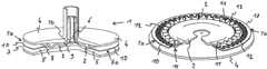
- FIG. 2is a schematic representation, in partial diametrical section, of a second exemplary embodiment of a fluid circulator, in this case circular, according to the invention
- FIG. 3is a schematic representation, in a partial sectional view, of a third exemplary embodiment of a fluid circulator, in this case longitudinal, according to the invention.
- FIG. 4is a schematic representation, in a side sectional view, of a fourth exemplary embodiment of a fluid circulator, in this case cylindrical, according to the invention.
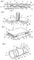
- FIG. 5is a perspective view of a first alternative embodiment of an element of the invention.
- FIG. 6is a perspective view of a second alternative embodiment of an element of the invention.
- FIG. 7is a perspective view of a fifth example of a fluid circulator.
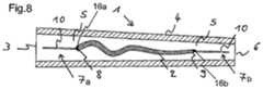
- FIG. 8is a schematic representation, in partial diametrical section, of another exemplary embodiment of a fluid circulator.
- a circulator 1having a deformable undulating membrane 2 in the form of a longitudinal strip, a fluid intake port 3 , a pump housing 4 delimiting a propulsion chamber 5 , and a discharge port 6 is partially shown.
- the undulating membrane 2is paired with a drive means permitting an undulating movement of the membrane 2 between the upstream 8 and downstream 9 edges thereof, said drive means as well as the elements for connection to the membrane featuring in the application FR 2 744 769 and not being shown in the appended FIGS. 1 to 6 in order to make same easier to interpret.
- the drive meansadvantageously consists of an actuator connected directly or via a connection element to the upstream edge of the membrane 2 .
- an undulation that propagates from the upstream edge 8 towards the downstream edge 9 of the membrane 2can be created.
- the fluidis introduced into the propulsion chamber 5 via the intake port 3 and then moved towards the discharge port 6 by means of the undulations of the membrane 2 .
- the circulator 1is equipped with means 7 for guiding the fluid.
- FIG. 1shows guiding means 7 disposed in the propulsion chamber 5 upstream of the undulating membrane 2 .
- Said guiding means 7make it possible to channel the fluid flow in a direction substantially parallel to the displacement of the wave along the membrane 2 .
- the fluid arriving upstream of the membrane 2is prevented from moving transversely to the displacement of the wave by the guiding means 7 and, consequently, the fluid cannot flow above or below the membrane 2 depending on the undulations thereof. In this way, the pressure differential created by the undulation is no longer compensated by a transverse transfer of fluid, as in the case of the circulator described in the document FR 2 744 769.
- the pressure differentialwhich is therefore maintained, ensures good propulsion of the fluid by the part of the membrane near the upstream edge 8 , which thus becomes effective.
- the hydraulic power generated by the circulator 1is therefore increased.
- guiding means 7are also provided downstream of the membrane 2 close to the downstream edge 9 of the membrane 2 .
- the function of the guiding means 7 disposed downstreamis the same as that of those located upstream of the membrane 2 , i.e. making it possible to maintain a pressure differential by directing the fluid flow leaving the membrane 2 , thus ensuring good propulsion of the fluid by the downstream edge 9 . In this way, the entire membrane 2 is used effectively and the hydraulic power of the circulator 1 is increased.
- the guiding means 7comprise at least one baffle 10 .
- the baffle 10is advantageously made of a flexible material, such that it not only guides the fluid but also promotes the propulsion thereof.
- means for stimulating the flexible baffleare provided, whereby the stimulation of the baffle 10 and of the membrane are in phase opposition to one another.
- bafflemay be used in other embodiments.
- the baffle or baffles 10are disposed in parallel with the displacement of the wave along the membrane 2 .
- the baffle 10may also be slightly inclined in order to distribute the fluid differently between the space located above the membrane 2 and the space located below or in order to account for the position of the fluid intake port 3 or of the discharge port 6 .
- the baffle 10is secured, directly or via connection elements, to the pump housing 4 .
- the baffle 10 and the pump housingare integrally formed.
- a circular fluid circulator 1is shown, this type of circulator comprising a pump housing 4 and an undulating membrane 2 , said membrane being disc-shaped.
- a first baffle 10 in the form of a ring surrounding the membrane 2 at the upstream edge 8 thereof as well as a second baffle 10 disposed between the discharge port 6 and the downstream edge 9 of the membranecan be seen.
- the baffles 10operate in the same manner as those provided for the membrane 2 in the form of a longitudinal strip shown in FIG. 1 .
- baffles 10that are placed one above the other are provided upstream and/or downstream of the membrane 2 .
- three baffles placed one above the otherare shown.
- the use of a plurality of baffles 10 placed one above the othermakes it possible to separate the main flow into a plurality of secondary fluid flows that flow one above the other and makes it possible to channel each of said flows in an improved manner in order to obtain laminar flows.
- This advantageous featureis particularly suitable if the cross-section of the propulsion chamber 5 is large in the region of the baffles.
- a third type of circulator 1i.e. a cylindrical circulator in which the undulating membrane 2 is tubular, is shown.
- guiding means 7are also provided in the form of cylindrical baffles 10 disposed upstream and downstream of the membrane 2 .
- the baffles 10are disposed at a short distance from the edge of the undulating membrane 2 , or from the support thereof connecting same to the actuator, advantageously less than one fiftieth of the length separating the upstream 8 and downstream 9 edges of the undulating membrane 2 .
- the first guiding means 7 ais disposed at a distance from the upstream edge of the membrane 2 of less than one fiftieth of the length separating the upstream 8 and downstream 9 edges.
- the second guiding means 7 bmay be disposed at a distance from the downstream edge 9 of the membrane 2 of less than one fiftieth of the length separating the upstream 8 and downstream 9 edges.
- bafflesthat are further from the edges of the undulating membrane 2 may be used.
- FIG. 5an alternative embodiment of a circulator 1 is shown.
- This variantcomprises complementary guiding means 11 , said complementary guiding means 11 being disposed in a plane perpendicular to a plane in which the first guiding means 7 a extends and making it possible to prevent a circular motion of the fluid between the intake port 3 and the undulating membrane 2 .
- complementary guiding means 11can also be disposed in a plane perpendicular to a plane in which the second guiding means 7 b extends and they can also make it possible to prevent a circular motion of the fluid between the discharge port and the undulating membrane 2 .
- the complementary guiding means 11make it possible to increase the hydraulic power of the circulator 1 .
- the complementary guiding means 11are, as shown in FIG. 5 , fastened to the first guiding means 7 a ; advantageously, the first guiding means 7 a and the complementary guiding means 11 are integrally formed.
- the guiding means 7 a , 7 beach consist of baffles 10 , but in other embodiments different devices could be used to guide the flow, in particular by providing two separate flow inlets, each oriented towards the space above or below the membrane.
- the guiding means 7 a and/or 7 bcomprise heat transfer elements that make it possible to vary the fluidity of the fluid to be pumped and/or the temperature thereof.
- This embodiment of the guiding meansis shown in FIG. 6 , with heating elements 12 supported by the first guiding means.
- This examplealso features complementary guiding means 11 that also perform the function of heat diffusers, since they extend from the guiding means supporting the heating elements 12 .
- the heat transfer elements supported by the guiding means 7 a in this casecomprise the heating means 12 , but they may also comprise cooling means and/or a coolant circuit.
- the guiding means 7are not connected to the pump housing 4 but are secured between the drive means 13 of the membrane and the membrane 2 itself. Accordingly, the first guiding means 7 a is connected to a movable portion 14 of the drive means 13 via a spring-loaded connection, such that the first guiding means is guided in an elastically deformable manner relative to the movable portion 14 .
- the first guiding means 7 aconsists of a baffle 10 in the form of a crown and comprising cut-outs 15 in the region of the connection to the movable portion 14 so as to give the connection the effect of a spring.
- the first guiding means 7 amay be connected via a flexible connection 16 a to the upstream edge 8 of the membrane 2 , said first guiding means 7 a , together with the membrane 2 and the flexible connection 16 , forming a tight barrier between two different spaces of the propulsion chamber 5 .
- the second guiding means 7 bmay also be connected via a second flexible connection 16 b to the downstream edge 9 of the membrane 2 , said second guiding means 7 b , together with the membrane 2 and the second flexible connection 16 b , forming a tight barrier between two different spaces of the propulsion chamber 5 separated from one another by the membrane 2 .
- the guiding means 7 a , 7 b and the upstream 8 and downstream 9 edges of the membraneare connected to one another by first and second flexible connections 16 a , 16 b , respectively, making it possible to form a seal between the portion of the propulsion chamber located above the membrane and the portion located below. In this way, transverse flows of fluid between said two portions/spaces of the chamber are prevented during displacement of the wave along the membrane 2 .
Landscapes
- Engineering & Computer Science (AREA)
- Mechanical Engineering (AREA)
- General Engineering & Computer Science (AREA)
- Reciprocating Pumps (AREA)
Abstract
Description
Claims (13)
Applications Claiming Priority (3)
| Application Number | Priority Date | Filing Date | Title |
|---|---|---|---|
| FR1760583AFR3073578B1 (en) | 2017-11-10 | 2017-11-10 | FLUID CIRCULATOR WITH RINGING MEMBRANE |
| FR1760583 | 2017-11-10 | ||
| PCT/EP2018/080749WO2019092175A1 (en) | 2017-11-10 | 2018-11-09 | Undulating-membrane fluid circulator |
Publications (2)
| Publication Number | Publication Date |
|---|---|
| US20210172429A1 US20210172429A1 (en) | 2021-06-10 |
| US11512689B2true US11512689B2 (en) | 2022-11-29 |
Family
ID=60955259
Family Applications (1)
| Application Number | Title | Priority Date | Filing Date |
|---|---|---|---|
| US16/762,909Active2039-01-06US11512689B2 (en) | 2017-11-10 | 2018-11-09 | Undulating-membrane fluid circulator |
Country Status (7)
| Country | Link |
|---|---|
| US (1) | US11512689B2 (en) |
| EP (1) | EP3707381B8 (en) |
| JP (1) | JP7158061B2 (en) |
| CN (1) | CN111433460B (en) |
| AU (1) | AU2018365313B2 (en) |
| FR (1) | FR3073578B1 (en) |
| WO (1) | WO2019092175A1 (en) |
Cited By (3)
| Publication number | Priority date | Publication date | Assignee | Title |
|---|---|---|---|---|
| US12214182B2 (en) | 2017-11-29 | 2025-02-04 | CorWave SA | Implantable pump system having an undulating membrane with improved hydraulic performance |
| US12251550B2 (en) | 2022-04-26 | 2025-03-18 | CorWave SA | Blood pumps having an encapsulated actuator |
| US12257427B2 (en) | 2022-11-15 | 2025-03-25 | CorWave SA | Implantable heart pump systems including an improved apical connector and/or graft connector |
Families Citing this family (15)
| Publication number | Priority date | Publication date | Assignee | Title |
|---|---|---|---|---|
| US10166319B2 (en) | 2016-04-11 | 2019-01-01 | CorWave SA | Implantable pump system having a coaxial ventricular cannula |
| US9968720B2 (en) | 2016-04-11 | 2018-05-15 | CorWave SA | Implantable pump system having an undulating membrane |
| EP3600479B1 (en) | 2017-03-31 | 2024-11-06 | CorWave SA | Implantable pump system having a rectangular membrane |
| FR3073578B1 (en) | 2017-11-10 | 2019-12-13 | Corwave | FLUID CIRCULATOR WITH RINGING MEMBRANE |
| WO2020188453A1 (en) | 2019-03-15 | 2020-09-24 | CorWave SA | Systems and methods for controlling an implantable blood pump |
| FR3099748B1 (en)* | 2019-08-09 | 2023-07-28 | Finx | Device for moving a watercraft |
| CN110425119B (en)* | 2019-08-21 | 2025-01-24 | 劳特士(嘉兴)机械设备有限公司 | A pneumatic pumping device |
| US11191946B2 (en) | 2020-03-06 | 2021-12-07 | CorWave SA | Implantable blood pumps comprising a linear bearing |
| FR3137658A1 (en)* | 2022-07-05 | 2024-01-12 | Finx | MULTI-DIRECTIONAL MEMBRANE FLUIDIC FLOW GENERATING DEVICE |
| WO2024105583A1 (en) | 2022-11-15 | 2024-05-23 | CorWave SA | Implantable heart pump system including an improved apical connector and/or graft connector |
| FR3144231A1 (en)* | 2022-12-23 | 2024-06-28 | Finx | HYDRAULIC PROPELLER INCLUDING AN IMMERSED ELECTRONIC BOARD |
| FR3144105A1 (en)* | 2022-12-23 | 2024-06-28 | Finx | system for tensioning a membrane equipping a fluid flow generator device |
| US12416301B2 (en)* | 2023-01-11 | 2025-09-16 | Southwest Research Institute | Traveling wave fluid energy machine |
| FR3147332A1 (en)* | 2023-03-31 | 2024-10-04 | Finx | FLUID FLOW GENERATING DEVICE COMPRISING A MEMBRANE WITH DECREASING STIFFNESS |
| FR3147242A1 (en)* | 2023-03-31 | 2024-10-04 | Finx | MOBILE DEFLECTOR FOR MEMBRANE FLUID FLOW GENERATING DEVICE |
Citations (155)
| Publication number | Priority date | Publication date | Assignee | Title |
|---|---|---|---|---|
| FR355700A (en) | 1905-06-28 | 1905-11-09 | Leopold Selme | Turbine with undulating membranes, reversible as a pump |
| GB662047A (en) | 1949-11-21 | 1951-11-28 | George Aksel Thiberg | Improvements in diaphragm pumps and compressors |
| US2842067A (en) | 1954-10-12 | 1958-07-08 | Stevens Ronald John | Pumps for fluids, more especially liquids |
| US3107630A (en) | 1955-01-31 | 1963-10-22 | Textron Inc | Non-magnetic electro-hydraulic pump |
| US3165061A (en) | 1963-02-18 | 1965-01-12 | Edward H Smith | Method and apparatus employing acoustic energy for increasing fluid flow |
| US3608088A (en) | 1969-04-17 | 1971-09-28 | Univ Minnesota | Implantable blood pump |
| US3620651A (en) | 1969-02-07 | 1971-11-16 | Int Combustion Holdings Ltd | Fluid flow apparatus |
| US3743446A (en) | 1971-07-12 | 1973-07-03 | Atek Ind Inc | Standing wave pump |
| US3765175A (en) | 1970-12-30 | 1973-10-16 | J Ohnaka | Fluid driven propulsion and generator mechanism |
| US4063826A (en) | 1975-05-20 | 1977-12-20 | Waldemar Riepe | Flexible, oscillating blade liquid pump |
| US4277706A (en) | 1979-04-16 | 1981-07-07 | Nu-Tech Industries, Inc. | Actuator for heart pump |
| US4384830A (en) | 1979-03-22 | 1983-05-24 | Wakelin Russell R F | Methods of and/or apparatus for displacing fluids |
| US4484095A (en) | 1982-02-27 | 1984-11-20 | Dornier System Gmbh | Stepping motor |
| US4488854A (en) | 1982-04-12 | 1984-12-18 | Miller Richard B | Constrained wave pump |
| US4498851A (en)* | 1980-05-02 | 1985-02-12 | Piezo Electric Products, Inc. | Solid state blower |
| US4648807A (en) | 1985-05-14 | 1987-03-10 | The Garrett Corporation | Compact piezoelectric fluidic air supply pump |
| US4753221A (en) | 1986-10-22 | 1988-06-28 | Intravascular Surgical Instruments, Inc. | Blood pumping catheter and method of use |
| WO1989010763A1 (en) | 1988-05-03 | 1989-11-16 | Nimbus Medical, Inc. | High-frequency transvalvular axisymmetric blood pump |
| US4918383A (en) | 1987-01-20 | 1990-04-17 | Huff Richard E | Membrane probe with automatic contact scrub action |
| US4931036A (en) | 1987-03-18 | 1990-06-05 | Aisin Seiki Kabushiki Kaisha | Intra-aortic balloon pump |
| US4939405A (en) | 1987-12-28 | 1990-07-03 | Misuzuerie Co. Ltd. | Piezo-electric vibrator pump |
| WO1990008260A1 (en) | 1989-01-23 | 1990-07-26 | University Of South Florida | Magnetically actuated positive displacement pump |
| US4955856A (en) | 1989-06-30 | 1990-09-11 | Phillips Steven J | Method and apparatus for installing a ventricular assist device cannulae |
| EP0412856A1 (en) | 1989-08-11 | 1991-02-13 | POMPES SALMSON Société Anonyme à directoire dite: | Device for the propulsion of a fluid |
| US4995857A (en) | 1989-04-07 | 1991-02-26 | Arnold John R | Left ventricular assist device and method for temporary and permanent procedures |
| US5147388A (en) | 1990-03-08 | 1992-09-15 | Kenji Yamazaki | Auxiliary artificial heart of the embedded-in-body type |
| US5263978A (en) | 1991-09-10 | 1993-11-23 | Forschungsgesellschaft Fur Biomedizinische Technik E.V. | Blood pump for pulsating operation |
| US5360445A (en) | 1991-11-06 | 1994-11-01 | International Business Machines Corporation | Blood pump actuator |
| US5370509A (en) | 1989-05-08 | 1994-12-06 | The Cleveland Clinic Foundation | Sealless rotodynamic pump with fluid bearing |
| US5525041A (en) | 1994-07-14 | 1996-06-11 | Deak; David | Momemtum transfer pump |
| US5588812A (en) | 1995-04-19 | 1996-12-31 | Nimbus, Inc. | Implantable electric axial-flow blood pump |
| FR2744769A1 (en) | 1996-02-12 | 1997-08-14 | Drevet Jean Baptiste | FLUID CIRCULATOR WITH VIBRATING MEMBRANE |
| US5840070A (en) | 1996-02-20 | 1998-11-24 | Kriton Medical, Inc. | Sealless rotary blood pump |
| US5982801A (en) | 1994-07-14 | 1999-11-09 | Quantum Sonic Corp., Inc | Momentum transfer apparatus |
| WO1999059652A1 (en) | 1998-05-15 | 1999-11-25 | A-Med Systems, Inc. | Pulmonary and circulatory blood flow support devices and methods for heart surgery procedures |
| US6030336A (en) | 1996-02-21 | 2000-02-29 | Synthelabo Biomedical (Societe Anonyme) | Pressure generator for a counterpressure cardiac assistance device |
| US6058593A (en) | 1997-04-02 | 2000-05-09 | Impella Cardiotechnick Gmbh | Method for producing a micro motor |
| CN1257006A (en) | 1998-11-03 | 2000-06-21 | 三星电子株式会社 | Miniature jetting device and method for making same |
| US6079214A (en) | 1998-08-06 | 2000-06-27 | Face International Corporation | Standing wave pump |
| US6083260A (en) | 1997-07-11 | 2000-07-04 | A-Med Systems, Inc. | Reverse flow transport pump and organ stabilization apparatus including related methods |
| US6116862A (en) | 1996-06-25 | 2000-09-12 | Medos Medizintechnik Gmbh | Blood pump |
| US6176848B1 (en) | 1996-04-04 | 2001-01-23 | Impella Cardiotechnik Gmbh | Intravascular blood pump |
| US6176822B1 (en) | 1998-03-31 | 2001-01-23 | Impella Cardiotechnik Gmbh | Intracardiac blood pump |
| US6346071B1 (en) | 1999-07-16 | 2002-02-12 | World Heart Corporation | Inflow conduit assembly for a ventricular assist device |
| US6395026B1 (en) | 1998-05-15 | 2002-05-28 | A-Med Systems, Inc. | Apparatus and methods for beating heart bypass surgery |
| CN1355715A (en) | 1999-06-10 | 2002-06-26 | 阳光心脏有限公司 | Heart assist devices, system and methods |
| US20020095210A1 (en) | 2001-01-16 | 2002-07-18 | Finnegan Michael T. | Heart pump graft connector and system |
| US20020146333A1 (en) | 1998-08-11 | 2002-10-10 | Jean-Baptiste Drevet | Vibrating membrane fluid circulator |
| US20020165426A1 (en) | 2001-04-20 | 2002-11-07 | Deutsches Zentrum Fur Luft-Und Raumfahrt E.V. | Left ventricular assist system |
| US20030002325A1 (en) | 2001-06-28 | 2003-01-02 | Atila Alvandpour | Current leakage reduction for loaded bit-lines in on-chip memory structures |
| US6530876B1 (en) | 2000-04-25 | 2003-03-11 | Paul A. Spence | Supplemental heart pump methods and systems for supplementing blood through the heart |
| US6658740B2 (en) | 2001-03-16 | 2003-12-09 | Wahl Clipper Corporation | Blade assembly for a vibrator motor |
| US20040002624A1 (en) | 2002-06-26 | 2004-01-01 | Yu Long Sheng | Ventricular connector |
| US6672847B2 (en) | 2001-12-27 | 2004-01-06 | Pratt & Whitney Canada Corp. | Standing wave excitation cavity fluid pump |
| US6723039B2 (en) | 2001-04-27 | 2004-04-20 | The Foundry, Inc. | Methods, systems and devices relating to implantable fluid pumps |
| US6726648B2 (en) | 2000-08-14 | 2004-04-27 | The University Of Miami | Valved apical conduit with trocar for beating-heart ventricular assist device placement |
| US6848001B1 (en) | 1999-07-21 | 2005-01-25 | Fujitsu Limited | Logical path establishing method and storage medium |
| US20050031474A1 (en)* | 2001-10-23 | 2005-02-10 | Wilhelm Zackl | Valveless pump |
| EP1551500A2 (en) | 2002-06-11 | 2005-07-13 | Walid Najib Aboul-Hosn | Percutaneously introduced blood pump and related methods |
| US20050261543A1 (en) | 2004-05-18 | 2005-11-24 | Yusuke Abe | Implantable artificial ventricular assist device |
| US20050288543A1 (en) | 2004-06-07 | 2005-12-29 | Stenberg Mattias G | Multi-chamber self-regulating ventricular assist device |
| CN1714759A (en) | 2004-05-28 | 2006-01-04 | 伊西康内外科公司 | Bi-directional infuser pump with volume braking for hydraulically controlling an adjustable gastric band |
| FR2861910B1 (en) | 2003-10-29 | 2006-01-13 | Jean Baptiste Drevet | ELECTROMAGNETIC MACHINE WITH DEFORMABLE MEMBRANE AND ELECTROMAGNETIC MOTOR ADAPTED TO SUCH A MACHINE |
| US20060014999A1 (en) | 2004-07-19 | 2006-01-19 | Heilman Marlin S | Devices, systems and methods for assisting blood flow |
| US7011620B1 (en) | 1999-12-04 | 2006-03-14 | Impella Cardiosystems Ag | Intravascular blood pump |
| US7027875B2 (en) | 2000-12-01 | 2006-04-11 | Impella Cardiosystems Ag | Intravascular pump |
| US20060288543A1 (en) | 2000-03-27 | 2006-12-28 | Lubera Daniel J | Resilient clip fastener |
| US7182727B2 (en) | 1997-07-11 | 2007-02-27 | A—Med Systems Inc. | Single port cardiac support apparatus |
| WO2007053881A1 (en) | 2005-11-08 | 2007-05-18 | Ventrassist Pty Ltd | Improvements to control systems and power systems for rotary blood pumps |
| US20070299297A1 (en) | 2006-06-26 | 2007-12-27 | Robert Jarvik | Textured conforming shell for stabilization of the interface of precision heart assist device components to tissues |
| FR2905147A1 (en) | 2006-08-25 | 2008-02-29 | Ubbink Garden B V | Fluid circulating pump for e.g. swimming pool, has body defining annular space, where diameter of body is thirteen centimeter, and motor oscillating periphery of membrane whose thickness increased from its outer diameter to inner diameter |
| US20080232987A1 (en)* | 2006-11-28 | 2008-09-25 | S.A.M. Amstar | Diaphragm circulator |
| EP1981585A2 (en) | 2006-01-27 | 2008-10-22 | Circulite, Inc. | Heart assist system |
| EP1644639B1 (en) | 2003-06-30 | 2009-02-11 | Nxp B.V. | Device for generating sound by means of a medium stream generated |
| US20090082778A1 (en) | 2007-09-25 | 2009-03-26 | Correx, Inc. | Applicator, assembly, and method for connecting an inlet conduit to a hollow organ |
| US7520850B2 (en) | 2003-11-19 | 2009-04-21 | Transoma Medical, Inc. | Feedback control and ventricular assist devices |
| CN101472627A (en) | 2006-01-30 | 2009-07-01 | 国立成功大学 | Dual-pulsation bi-ventricular assist device |
| CA2712945A1 (en) | 2008-01-23 | 2009-07-30 | Deka Products Limited Partnership | Pump cassette and methods for use in medical treatment system using a plurality of fluid lines |
| EP2152339A1 (en) | 2007-08-29 | 2010-02-17 | Circulite, Inc. | Cannula insertion devices, systems, and methods including a compressible member |
| US7696634B2 (en) | 2007-05-01 | 2010-04-13 | Pliant Energy Systems Llc | Pliant mechanisms for extracting power from moving fluid |
| US7736296B2 (en) | 2004-10-14 | 2010-06-15 | Abiomed Europe Gmbh | Intracardiac blood pump |
| US20100234941A1 (en) | 2007-08-17 | 2010-09-16 | Thomas Finocchiaro | Linear drive and pump system, in particular an artificial heart |
| US20100241223A1 (en) | 2007-06-06 | 2010-09-23 | WorldHeart, Inc. | Wearable vad controller with reserve battery |
| CN101878049A (en) | 2007-09-28 | 2010-11-03 | 阿斯顿大学 | pulsating blood pump |
| EP2249746A1 (en) | 2008-02-08 | 2010-11-17 | Heartware, Inc. | Ventricular assist device for intraventricular placement |
| EP2310067A1 (en) | 2008-07-25 | 2011-04-20 | Calon Cardio Technology Ltd | Heart assist apparatus |
| WO2011056823A2 (en) | 2009-11-03 | 2011-05-12 | Coherex Medical, Inc. | Ventricular assist device and related methods |
| CN102112744A (en) | 2008-08-01 | 2011-06-29 | Amsr&D联合股份有限公司 | Improved crinkle diaphragm pump |
| US20110176946A1 (en)* | 2008-08-01 | 2011-07-21 | Ams R&D Sas | Diaphragm pump with a crinkle diaphragm of improved efficiency |
| US7988728B2 (en) | 2002-09-30 | 2011-08-02 | Thoratec Corporation | Physiological demand responsive control system |
| US8012079B2 (en) | 2004-08-13 | 2011-09-06 | Procyrion, Inc. | Method and apparatus for long-term assisting a left ventricle to pump blood |
| US20110260449A1 (en) | 2010-04-21 | 2011-10-27 | Pokorney James L | Apical access and control devices |
| US8152845B2 (en) | 2009-12-30 | 2012-04-10 | Thoratec Corporation | Blood pump system with mounting cuff |
| US20120089225A1 (en) | 2010-10-07 | 2012-04-12 | EverHeart Systems LLC | High efficiency blood pump |
| US8167593B2 (en) | 2009-04-16 | 2012-05-01 | The Board Of Regents Of The University Of Texas System | System and method for pump with deformable bearing surface |
| US20120323318A1 (en) | 2010-03-03 | 2012-12-20 | Seikh Mohammad Yusuf | Flexible magnetic membrane based actuation system and devices involving the same |
| US8343029B2 (en) | 2007-10-24 | 2013-01-01 | Circulite, Inc. | Transseptal cannula, tip, delivery system, and method |
| US8366401B2 (en) | 2009-04-16 | 2013-02-05 | The Board Of Regents Of The University Of Texas Systems | Positive displacement pump system and method with rotating valve |
| US20130042753A1 (en) | 2010-02-27 | 2013-02-21 | Knf Neuberger Gmbh | Diaphragm pump |
| US8394009B2 (en) | 2010-03-05 | 2013-03-12 | Minnetronix, Inc. | Portable controller with integral power source for mechanical circulation support systems |
| US8432057B2 (en) | 2007-05-01 | 2013-04-30 | Pliant Energy Systems Llc | Pliant or compliant elements for harnessing the forces of moving fluid to transport fluid or generate electricity |
| AU2013203301A1 (en) | 2006-05-31 | 2013-05-02 | Star Bp, Inc. | Heart Assist Device |
| US8449444B2 (en) | 2009-02-27 | 2013-05-28 | Thoratec Corporation | Blood flow meter |
| EP2600918A1 (en) | 2010-08-06 | 2013-06-12 | Heartware, Inc. | Conduit device for use with a ventricular assist device |
| KR20130068373A (en) | 2011-12-15 | 2013-06-26 | (주)에스티아이 | Fixing apparatus for flexible thin film substrate |
| US20130178694A1 (en) | 2012-01-05 | 2013-07-11 | Terumo Kabushiki Kaisha | Apical ring for ventricular assist device |
| US8512012B2 (en) | 2004-03-18 | 2013-08-20 | Circulite, Inc. | Pump |
| US20130267779A1 (en) | 2012-04-05 | 2013-10-10 | Brady Woolford | Control for surgical fluid management pump system |
| US8556795B2 (en) | 2010-11-23 | 2013-10-15 | Minnetronix Inc. | Portable controller with integral power source for mechanical circulation support systems |
| US8562508B2 (en) | 2009-12-30 | 2013-10-22 | Thoratec Corporation | Mobility-enhancing blood pump system |
| US20130314047A1 (en) | 2012-05-24 | 2013-11-28 | Heartware, Inc. | Low-power battery pack with safety system |
| US8597350B2 (en) | 2010-12-09 | 2013-12-03 | Heartware, Inc. | Controller and power source for implantable blood pump |
| US8610304B2 (en) | 2007-05-01 | 2013-12-17 | Pliant Energy Systems Llc | Mechanisms for creating undulating motion, such as for propulsion, and for harnessing the energy of moving fluid |
| EP2517739B1 (en) | 2011-02-28 | 2013-12-25 | Fundacja Rozwoju Kardiochirurgii Im. Prof. Zbigniewa Religi | Blood pump, in particular implantable pneumatic heart assist device |
| US20140023533A1 (en) | 2011-04-15 | 2014-01-23 | Techno Takatsuki Co., Ltd. | Electromagnetic vibrating diaphragm pump |
| EP2704761A1 (en) | 2011-05-05 | 2014-03-12 | Berlin Heart GmbH | Blood pump |
| EP2753389A1 (en) | 2011-09-07 | 2014-07-16 | CircuLite, Inc. | Cannula tips, tissue attachment rings, and methods of delivering and using the same |
| US8784291B2 (en) | 2007-10-24 | 2014-07-22 | Circulite, Inc. | Transseptal cannula, tip, delivery system, and method |
| US20140207232A1 (en) | 2011-07-28 | 2014-07-24 | Fineheart | Removable heart pump, and method implemented in such a pump |
| US20140277423A1 (en) | 2013-03-12 | 2014-09-18 | St. Jude Medical, Cardiology Division, Inc. | Self-actuating sealing portions for paravalvular leak protection |
| US20140275723A1 (en) | 2013-03-14 | 2014-09-18 | Circulite, Inc. | Magnetically levitated and driven blood pump and method for using the same |
| US20140316426A1 (en) | 2011-05-16 | 2014-10-23 | Berlin Heart Gmbh | Connection system for the detachable fixation of a hollow cylindrical component at a recess |
| US8976546B2 (en) | 2011-07-29 | 2015-03-10 | Shenzhen Byd Auto R&D Company Limited | Control integrated circuit of a switch power supply and a switch power supply using the same |
| US20150167659A1 (en) | 2011-08-25 | 2015-06-18 | Ecolab Usa Inc. | Diaphragm pump for dosing a fluid capable of automatic degassing and an according method |
| US9089635B2 (en) | 2010-06-22 | 2015-07-28 | Thoratec Corporation | Apparatus and method for modifying pressure-flow characteristics of a pump |
| US9144669B2 (en) | 2005-11-16 | 2015-09-29 | Heartware, Inc. | Implantation procedure for blood pumps |
| US9145875B2 (en) | 2007-05-01 | 2015-09-29 | Pliant Energy Systems Llc | Ribbon transducer and pump apparatuses, methods and systems |
| US20150330383A1 (en)* | 2014-05-14 | 2015-11-19 | Saint-Gobain Performance Plastics France | Membrane pump |
| US20160038664A1 (en) | 2012-03-05 | 2016-02-11 | Thoratec Corporation | Modular implantable medical pump |
| US20160051738A1 (en) | 2012-08-31 | 2016-02-25 | Thoratec Corporation | Ventricular cuff |
| US20160235899A1 (en) | 2015-02-12 | 2016-08-18 | Thoratec Corporation | System and method for controlling the position of a levitated rotor |
| FR3032917A1 (en) | 2015-02-20 | 2016-08-26 | Valeo Systemes Thermiques | AIR CONDITIONING MODULE OF A MOTOR VEHICLE |
| US9446180B2 (en) | 2013-01-04 | 2016-09-20 | Heartware, Inc. | Controller and power source for implantable blood pump |
| WO2016179262A1 (en) | 2015-05-04 | 2016-11-10 | Yeoman & Company | Hand tool handle assembly and method of manufacture |
| US9526819B2 (en) | 2014-09-26 | 2016-12-27 | Ch Biomedical (Usa), Inc. | Ventricular assist device controller with integrated power source |
| US20170012491A1 (en) | 2015-07-06 | 2017-01-12 | Levitronix Gmbh | Electromagnetic rotary drive |
| US9572915B2 (en) | 2012-03-26 | 2017-02-21 | Procyrion, Inc. | Systems and methods for fluid flows and/or pressures for circulation and perfusion enhancement |
| CN106421939A (en) | 2011-02-16 | 2017-02-22 | 塞奎阿纳医疗股份公司 | Apparatus and methods for treating intracorporeal fluid accumulation |
| EP3145558A2 (en) | 2014-05-20 | 2017-03-29 | CircuLite, Inc. | Heart assist systems and methods |
| US9616158B2 (en) | 2013-12-04 | 2017-04-11 | Heartware, Inc. | Molded VAD |
| WO2017087785A1 (en) | 2015-11-20 | 2017-05-26 | Tc1 Llc | Energy management of blood pump controllers |
| WO2017087717A1 (en) | 2015-11-20 | 2017-05-26 | Tc1 Llc | Blood pump controllers having daisy-chained batteries |
| US9694123B2 (en) | 2014-04-15 | 2017-07-04 | Tc1 Llc | Methods and systems for controlling a blood pump |
| US9744279B2 (en) | 2005-12-08 | 2017-08-29 | Heartware, Inc. | Implant connector |
| US20170266358A1 (en) | 2016-03-18 | 2017-09-21 | Everheart Systems Inc. | Cardiac connection for ventricular assist device |
| US9786150B2 (en) | 2014-04-15 | 2017-10-10 | Tci Llc | Methods and systems for providing battery feedback to patient |
| US20170290966A1 (en) | 2016-04-11 | 2017-10-12 | CorWave SA | Implantable pump system having an undulating membrane |
| US20170290967A1 (en) | 2016-04-11 | 2017-10-12 | CorWave SA | Implantable pump system having a coaxial ventricular cannula |
| US20180038364A1 (en) | 2016-08-02 | 2018-02-08 | Zodiac Aerotechnics | Method for operating an undulating diaphragm pump and an undulating diaphragm pump operating system |
| US20180050143A1 (en) | 2016-08-22 | 2018-02-22 | Tc1 Llc | Heart pump cuff |
| US20180369469A1 (en) | 2017-03-31 | 2018-12-27 | CorWave SA | Implantable pump system having a rectangular membrane |
| US10188779B1 (en) | 2017-11-29 | 2019-01-29 | CorWave SA | Implantable pump system having an undulating membrane with improved hydraulic performance |
| WO2019092175A1 (en) | 2017-11-10 | 2019-05-16 | Ams R&D Sas | Undulating-membrane fluid circulator |
| WO2020115607A2 (en) | 2018-12-05 | 2020-06-11 | CorWave SA | Apparatus and methods for coupling a blood pump to the heart |
| US10799625B2 (en) | 2019-03-15 | 2020-10-13 | CorWave SA | Systems and methods for controlling an implantable blood pump |
- 2017
- 2017-11-10FRFR1760583Apatent/FR3073578B1/enactiveActive
- 2018
- 2018-11-09WOPCT/EP2018/080749patent/WO2019092175A1/ennot_activeCeased
- 2018-11-09JPJP2020525986Apatent/JP7158061B2/enactiveActive
- 2018-11-09AUAU2018365313Apatent/AU2018365313B2/enactiveActive
- 2018-11-09USUS16/762,909patent/US11512689B2/enactiveActive
- 2018-11-09CNCN201880078891.9Apatent/CN111433460B/enactiveActive
- 2018-11-09EPEP18810891.4Apatent/EP3707381B8/enactiveActive
Patent Citations (233)
| Publication number | Priority date | Publication date | Assignee | Title |
|---|---|---|---|---|
| FR355700A (en) | 1905-06-28 | 1905-11-09 | Leopold Selme | Turbine with undulating membranes, reversible as a pump |
| GB662047A (en) | 1949-11-21 | 1951-11-28 | George Aksel Thiberg | Improvements in diaphragm pumps and compressors |
| US2842067A (en) | 1954-10-12 | 1958-07-08 | Stevens Ronald John | Pumps for fluids, more especially liquids |
| US3107630A (en) | 1955-01-31 | 1963-10-22 | Textron Inc | Non-magnetic electro-hydraulic pump |
| US3165061A (en) | 1963-02-18 | 1965-01-12 | Edward H Smith | Method and apparatus employing acoustic energy for increasing fluid flow |
| US3620651A (en) | 1969-02-07 | 1971-11-16 | Int Combustion Holdings Ltd | Fluid flow apparatus |
| US3608088A (en) | 1969-04-17 | 1971-09-28 | Univ Minnesota | Implantable blood pump |
| US3765175A (en) | 1970-12-30 | 1973-10-16 | J Ohnaka | Fluid driven propulsion and generator mechanism |
| US3743446A (en) | 1971-07-12 | 1973-07-03 | Atek Ind Inc | Standing wave pump |
| US4063826A (en) | 1975-05-20 | 1977-12-20 | Waldemar Riepe | Flexible, oscillating blade liquid pump |
| US4384830A (en) | 1979-03-22 | 1983-05-24 | Wakelin Russell R F | Methods of and/or apparatus for displacing fluids |
| US4277706A (en) | 1979-04-16 | 1981-07-07 | Nu-Tech Industries, Inc. | Actuator for heart pump |
| US4498851A (en)* | 1980-05-02 | 1985-02-12 | Piezo Electric Products, Inc. | Solid state blower |
| US4484095A (en) | 1982-02-27 | 1984-11-20 | Dornier System Gmbh | Stepping motor |
| US4488854A (en) | 1982-04-12 | 1984-12-18 | Miller Richard B | Constrained wave pump |
| US4648807A (en) | 1985-05-14 | 1987-03-10 | The Garrett Corporation | Compact piezoelectric fluidic air supply pump |
| US4753221A (en) | 1986-10-22 | 1988-06-28 | Intravascular Surgical Instruments, Inc. | Blood pumping catheter and method of use |
| US4918383A (en) | 1987-01-20 | 1990-04-17 | Huff Richard E | Membrane probe with automatic contact scrub action |
| US4931036A (en) | 1987-03-18 | 1990-06-05 | Aisin Seiki Kabushiki Kaisha | Intra-aortic balloon pump |
| US4939405A (en) | 1987-12-28 | 1990-07-03 | Misuzuerie Co. Ltd. | Piezo-electric vibrator pump |
| WO1989010763A1 (en) | 1988-05-03 | 1989-11-16 | Nimbus Medical, Inc. | High-frequency transvalvular axisymmetric blood pump |
| US4906229A (en) | 1988-05-03 | 1990-03-06 | Nimbus Medical, Inc. | High-frequency transvalvular axisymmetric blood pump |
| EP0415949A1 (en) | 1988-05-03 | 1991-03-13 | Nimbus Medical Inc | TRANSVALVULAR, AXIS-SYMMETRIC HIGH-FREQUENCY BLOOD PUMP. |
| WO1990008260A1 (en) | 1989-01-23 | 1990-07-26 | University Of South Florida | Magnetically actuated positive displacement pump |
| US4995857A (en) | 1989-04-07 | 1991-02-26 | Arnold John R | Left ventricular assist device and method for temporary and permanent procedures |
| US5370509A (en) | 1989-05-08 | 1994-12-06 | The Cleveland Clinic Foundation | Sealless rotodynamic pump with fluid bearing |
| US4955856A (en) | 1989-06-30 | 1990-09-11 | Phillips Steven J | Method and apparatus for installing a ventricular assist device cannulae |
| EP0412856A1 (en) | 1989-08-11 | 1991-02-13 | POMPES SALMSON Société Anonyme à directoire dite: | Device for the propulsion of a fluid |
| FR2650862B1 (en) | 1989-08-11 | 1991-11-08 | Salmson Pompes | DEVICE FOR PROPELLING A FLUID |
| US5147388A (en) | 1990-03-08 | 1992-09-15 | Kenji Yamazaki | Auxiliary artificial heart of the embedded-in-body type |
| US5275580A (en) | 1990-03-08 | 1994-01-04 | Kenji Yamazaki | Auxiliary artificial heart of the embedded-in-body type |
| EP0445782B1 (en) | 1990-03-08 | 1994-08-10 | Sun Medical Technology Research Corporation | Auxiliary artificial heart of the embedded-in-body type |
| US5263978A (en) | 1991-09-10 | 1993-11-23 | Forschungsgesellschaft Fur Biomedizinische Technik E.V. | Blood pump for pulsating operation |
| US5360445A (en) | 1991-11-06 | 1994-11-01 | International Business Machines Corporation | Blood pump actuator |
| US5525041A (en) | 1994-07-14 | 1996-06-11 | Deak; David | Momemtum transfer pump |
| US5982801A (en) | 1994-07-14 | 1999-11-09 | Quantum Sonic Corp., Inc | Momentum transfer apparatus |
| US5588812A (en) | 1995-04-19 | 1996-12-31 | Nimbus, Inc. | Implantable electric axial-flow blood pump |
| FR2744769A1 (en) | 1996-02-12 | 1997-08-14 | Drevet Jean Baptiste | FLUID CIRCULATOR WITH VIBRATING MEMBRANE |
| WO1997029282A1 (en) | 1996-02-12 | 1997-08-14 | Drevet Jean Baptiste | Fluid circulator with a vibrating membrane |
| FR2744769B1 (en) | 1996-02-12 | 1999-02-12 | Drevet Jean Baptiste | FLUID CIRCULATOR WITH VIBRATING MEMBRANE |
| US6361284B2 (en) | 1996-02-12 | 2002-03-26 | Jean-Baptiste Drevet | Vibrating membrane fluid circulator |
| US20010001278A1 (en) | 1996-02-12 | 2001-05-17 | Jean-Baptiste Drevet | Vibrating membrane fluid circulator |
| US5840070A (en) | 1996-02-20 | 1998-11-24 | Kriton Medical, Inc. | Sealless rotary blood pump |
| US6030336A (en) | 1996-02-21 | 2000-02-29 | Synthelabo Biomedical (Societe Anonyme) | Pressure generator for a counterpressure cardiac assistance device |
| EP0961621B1 (en) | 1996-04-04 | 2004-07-07 | Impella CardioSystems AG | Intravascular blood pump |
| US6176848B1 (en) | 1996-04-04 | 2001-01-23 | Impella Cardiotechnik Gmbh | Intravascular blood pump |
| US6116862A (en) | 1996-06-25 | 2000-09-12 | Medos Medizintechnik Gmbh | Blood pump |
| US6058593A (en) | 1997-04-02 | 2000-05-09 | Impella Cardiotechnick Gmbh | Method for producing a micro motor |
| EP0925081B1 (en) | 1997-04-02 | 2003-12-03 | Impella Cardiotechnik Aktiengesellschaft | Intracardiac pump device |
| US6083260A (en) | 1997-07-11 | 2000-07-04 | A-Med Systems, Inc. | Reverse flow transport pump and organ stabilization apparatus including related methods |
| US6532964B2 (en) | 1997-07-11 | 2003-03-18 | A-Med Systems, Inc. | Pulmonary and circulatory blood flow support devices and methods for heart surgery procedures |
| US6123725A (en) | 1997-07-11 | 2000-09-26 | A-Med Systems, Inc. | Single port cardiac support apparatus |
| US6976996B1 (en) | 1997-07-11 | 2005-12-20 | A-Med Systems, Inc. | Transport pump and organ stabilization apparatus including related methods |
| US7182727B2 (en) | 1997-07-11 | 2007-02-27 | A—Med Systems Inc. | Single port cardiac support apparatus |
| US6935344B1 (en) | 1997-09-19 | 2005-08-30 | A-Med Systems, Inc. | Methods and systems for providing right and/or left heart support during cardiac surgery |
| US6176822B1 (en) | 1998-03-31 | 2001-01-23 | Impella Cardiotechnik Gmbh | Intracardiac blood pump |
| WO1999059652A1 (en) | 1998-05-15 | 1999-11-25 | A-Med Systems, Inc. | Pulmonary and circulatory blood flow support devices and methods for heart surgery procedures |
| US6395026B1 (en) | 1998-05-15 | 2002-05-28 | A-Med Systems, Inc. | Apparatus and methods for beating heart bypass surgery |
| US6079214A (en) | 1998-08-06 | 2000-06-27 | Face International Corporation | Standing wave pump |
| US20020146333A1 (en) | 1998-08-11 | 2002-10-10 | Jean-Baptiste Drevet | Vibrating membrane fluid circulator |
| US6659740B2 (en) | 1998-08-11 | 2003-12-09 | Jean-Baptiste Drevet | Vibrating membrane fluid circulator |
| CN1257006A (en) | 1998-11-03 | 2000-06-21 | 三星电子株式会社 | Miniature jetting device and method for making same |
| US20120220816A1 (en) | 1999-06-10 | 2012-08-30 | Sunshine Heart Company PTY, LTD | Heart assist devices, systems and methods |
| CN1355715A (en) | 1999-06-10 | 2002-06-26 | 阳光心脏有限公司 | Heart assist devices, system and methods |
| US6346071B1 (en) | 1999-07-16 | 2002-02-12 | World Heart Corporation | Inflow conduit assembly for a ventricular assist device |
| US6848001B1 (en) | 1999-07-21 | 2005-01-25 | Fujitsu Limited | Logical path establishing method and storage medium |
| EP1233797B1 (en) | 1999-12-04 | 2006-07-19 | Impella CardioSystems GmbH | Intravascular blood pump |
| US7011620B1 (en) | 1999-12-04 | 2006-03-14 | Impella Cardiosystems Ag | Intravascular blood pump |
| US20060288543A1 (en) | 2000-03-27 | 2006-12-28 | Lubera Daniel J | Resilient clip fastener |
| US6530876B1 (en) | 2000-04-25 | 2003-03-11 | Paul A. Spence | Supplemental heart pump methods and systems for supplementing blood through the heart |
| US6726648B2 (en) | 2000-08-14 | 2004-04-27 | The University Of Miami | Valved apical conduit with trocar for beating-heart ventricular assist device placement |
| EP1337288B1 (en) | 2000-12-01 | 2008-03-12 | Abiomed Europe GmbH | Intravascular pump |
| US7027875B2 (en) | 2000-12-01 | 2006-04-11 | Impella Cardiosystems Ag | Intravascular pump |
| US20020095210A1 (en) | 2001-01-16 | 2002-07-18 | Finnegan Michael T. | Heart pump graft connector and system |
| US6658740B2 (en) | 2001-03-16 | 2003-12-09 | Wahl Clipper Corporation | Blade assembly for a vibrator motor |
| US20020165426A1 (en) | 2001-04-20 | 2002-11-07 | Deutsches Zentrum Fur Luft-Und Raumfahrt E.V. | Left ventricular assist system |
| US6723039B2 (en) | 2001-04-27 | 2004-04-20 | The Foundry, Inc. | Methods, systems and devices relating to implantable fluid pumps |
| US20030002325A1 (en) | 2001-06-28 | 2003-01-02 | Atila Alvandpour | Current leakage reduction for loaded bit-lines in on-chip memory structures |
| US20050031474A1 (en)* | 2001-10-23 | 2005-02-10 | Wilhelm Zackl | Valveless pump |
| US6811381B2 (en) | 2001-12-27 | 2004-11-02 | Pratt & Whitney Canada Corp. | Standing wave excitation cavity fluid pump method of operation |
| US6672847B2 (en) | 2001-12-27 | 2004-01-06 | Pratt & Whitney Canada Corp. | Standing wave excitation cavity fluid pump |
| EP1551500A2 (en) | 2002-06-11 | 2005-07-13 | Walid Najib Aboul-Hosn | Percutaneously introduced blood pump and related methods |
| US20060155158A1 (en) | 2002-06-11 | 2006-07-13 | Aboul-Hosn Walid N | Percutaneously introduced blood pump and related methods |
| US6732501B2 (en) | 2002-06-26 | 2004-05-11 | Heartware, Inc. | Ventricular connector |
| US20040002624A1 (en) | 2002-06-26 | 2004-01-01 | Yu Long Sheng | Ventricular connector |
| US7988728B2 (en) | 2002-09-30 | 2011-08-02 | Thoratec Corporation | Physiological demand responsive control system |
| US7889877B2 (en) | 2003-06-30 | 2011-02-15 | Nxp B.V. | Device for generating a medium stream |
| EP1644639B1 (en) | 2003-06-30 | 2009-02-11 | Nxp B.V. | Device for generating sound by means of a medium stream generated |
| FR2861910B1 (en) | 2003-10-29 | 2006-01-13 | Jean Baptiste Drevet | ELECTROMAGNETIC MACHINE WITH DEFORMABLE MEMBRANE AND ELECTROMAGNETIC MOTOR ADAPTED TO SUCH A MACHINE |
| US7323961B2 (en) | 2003-10-29 | 2008-01-29 | S.A.M. Amstar | Electromagnetic machine with a deformable membrane |
| US7520850B2 (en) | 2003-11-19 | 2009-04-21 | Transoma Medical, Inc. | Feedback control and ventricular assist devices |
| US8512012B2 (en) | 2004-03-18 | 2013-08-20 | Circulite, Inc. | Pump |
| US20050261543A1 (en) | 2004-05-18 | 2005-11-24 | Yusuke Abe | Implantable artificial ventricular assist device |
| CN1714759A (en) | 2004-05-28 | 2006-01-04 | 伊西康内外科公司 | Bi-directional infuser pump with volume braking for hydraulically controlling an adjustable gastric band |
| US20050288543A1 (en) | 2004-06-07 | 2005-12-29 | Stenberg Mattias G | Multi-chamber self-regulating ventricular assist device |
| US20060014999A1 (en) | 2004-07-19 | 2006-01-19 | Heilman Marlin S | Devices, systems and methods for assisting blood flow |
| US8012079B2 (en) | 2004-08-13 | 2011-09-06 | Procyrion, Inc. | Method and apparatus for long-term assisting a left ventricle to pump blood |
| US7736296B2 (en) | 2004-10-14 | 2010-06-15 | Abiomed Europe Gmbh | Intracardiac blood pump |
| WO2007053881A1 (en) | 2005-11-08 | 2007-05-18 | Ventrassist Pty Ltd | Improvements to control systems and power systems for rotary blood pumps |
| US9144669B2 (en) | 2005-11-16 | 2015-09-29 | Heartware, Inc. | Implantation procedure for blood pumps |
| US9080564B2 (en) | 2005-11-30 | 2015-07-14 | Ams R&D Sas | Diaphragm circulator |
| US20130078122A1 (en) | 2005-11-30 | 2013-03-28 | Ams R&D Sas | Diaphragm Circulator |
| US9744279B2 (en) | 2005-12-08 | 2017-08-29 | Heartware, Inc. | Implant connector |
| US8157720B2 (en) | 2006-01-27 | 2012-04-17 | Circulite, Inc. | Heart assist system |
| EP1981585A2 (en) | 2006-01-27 | 2008-10-22 | Circulite, Inc. | Heart assist system |
| US8465410B2 (en) | 2006-01-27 | 2013-06-18 | Circulite, Inc. | Heart assist system |
| CN101472627A (en) | 2006-01-30 | 2009-07-01 | 国立成功大学 | Dual-pulsation bi-ventricular assist device |
| AU2013203301B2 (en) | 2006-05-31 | 2015-10-29 | Star Bp, Inc. | Heart Assist Device |
| AU2013203301A1 (en) | 2006-05-31 | 2013-05-02 | Star Bp, Inc. | Heart Assist Device |
| US20070299297A1 (en) | 2006-06-26 | 2007-12-27 | Robert Jarvik | Textured conforming shell for stabilization of the interface of precision heart assist device components to tissues |
| FR2905147A1 (en) | 2006-08-25 | 2008-02-29 | Ubbink Garden B V | Fluid circulating pump for e.g. swimming pool, has body defining annular space, where diameter of body is thirteen centimeter, and motor oscillating periphery of membrane whose thickness increased from its outer diameter to inner diameter |
| US8333686B2 (en) | 2006-08-30 | 2012-12-18 | Circulite, Inc. | Cannula insertion devices, systems, and methods including a compressible member |
| US20080232987A1 (en)* | 2006-11-28 | 2008-09-25 | S.A.M. Amstar | Diaphragm circulator |
| US9145875B2 (en) | 2007-05-01 | 2015-09-29 | Pliant Energy Systems Llc | Ribbon transducer and pump apparatuses, methods and systems |
| US8610304B2 (en) | 2007-05-01 | 2013-12-17 | Pliant Energy Systems Llc | Mechanisms for creating undulating motion, such as for propulsion, and for harnessing the energy of moving fluid |
| US7863768B2 (en) | 2007-05-01 | 2011-01-04 | Pliant Energy Systems Llc | Pliant mechanisms for extracting power from moving fluid |
| US8432057B2 (en) | 2007-05-01 | 2013-04-30 | Pliant Energy Systems Llc | Pliant or compliant elements for harnessing the forces of moving fluid to transport fluid or generate electricity |
| US7839007B2 (en) | 2007-05-01 | 2010-11-23 | Pliant Energy Systems Llc | Pliant mechanisms for extracting power from moving fluid |
| US7696634B2 (en) | 2007-05-01 | 2010-04-13 | Pliant Energy Systems Llc | Pliant mechanisms for extracting power from moving fluid |
| US20100241223A1 (en) | 2007-06-06 | 2010-09-23 | WorldHeart, Inc. | Wearable vad controller with reserve battery |
| EP2164542B1 (en) | 2007-06-06 | 2016-08-10 | Worldheart Corporation | Wearable vad controller with reserve battery |
| US20100234941A1 (en) | 2007-08-17 | 2010-09-16 | Thomas Finocchiaro | Linear drive and pump system, in particular an artificial heart |
| EP2891502A1 (en) | 2007-08-29 | 2015-07-08 | CircuLite, Inc. | Cannula insertion devices, systems, and methods including a compressible member |
| EP2152339A1 (en) | 2007-08-29 | 2010-02-17 | Circulite, Inc. | Cannula insertion devices, systems, and methods including a compressible member |
| EP2152339B1 (en) | 2007-08-29 | 2015-05-06 | CircuLite, Inc. | Cannula insertion devices, systems, and methods including a compressible member |
| EP2891502B1 (en) | 2007-08-29 | 2016-07-06 | CircuLite, Inc. | Cannula insertion devices, systems, and methods including a compressible member |
| US20090082778A1 (en) | 2007-09-25 | 2009-03-26 | Correx, Inc. | Applicator, assembly, and method for connecting an inlet conduit to a hollow organ |
| CN101878049A (en) | 2007-09-28 | 2010-11-03 | 阿斯顿大学 | pulsating blood pump |
| US8394010B2 (en) | 2007-10-24 | 2013-03-12 | Circulite, Inc. | Anchoring guide element |
| US8343029B2 (en) | 2007-10-24 | 2013-01-01 | Circulite, Inc. | Transseptal cannula, tip, delivery system, and method |
| US9211367B2 (en) | 2007-10-24 | 2015-12-15 | Circulite, Inc. | Transseptal cannula, tip, delivery system, and method |
| US8784291B2 (en) | 2007-10-24 | 2014-07-22 | Circulite, Inc. | Transseptal cannula, tip, delivery system, and method |
| US8821366B2 (en) | 2007-10-24 | 2014-09-02 | Circulite, Inc. | Transseptal cannula, tip, delivery system, and method |
| US9022916B2 (en) | 2007-10-24 | 2015-05-05 | Circulite, Inc. | Transseptal cannula, tip, delivery system, and method |
| CA2712945A1 (en) | 2008-01-23 | 2009-07-30 | Deka Products Limited Partnership | Pump cassette and methods for use in medical treatment system using a plurality of fluid lines |
| JP2011509801A (en) | 2008-01-23 | 2011-03-31 | デカ・プロダクツ・リミテッド・パートナーシップ | Pump cassette and method for use in medical treatment systems using multiple fluid lines |
| EP2249746A1 (en) | 2008-02-08 | 2010-11-17 | Heartware, Inc. | Ventricular assist device for intraventricular placement |
| US8852072B2 (en) | 2008-02-08 | 2014-10-07 | Heartware, Inc. | Ventricular assist device for intraventricular placement |
| US9579437B2 (en) | 2008-02-08 | 2017-02-28 | Medtronic HeartWare, Inc. | Ventricular assist device for intraventricular placement |
| US9173984B2 (en) | 2008-02-08 | 2015-11-03 | Heartware, Inc. | Ventricular assist device for intraventricular placement |
| US9956333B2 (en) | 2008-02-08 | 2018-05-01 | Heartware, Inc. | Ventricular assist device for intraventricular placement |
| EP2310067A1 (en) | 2008-07-25 | 2011-04-20 | Calon Cardio Technology Ltd | Heart assist apparatus |
| US8550975B2 (en) | 2008-07-25 | 2013-10-08 | Calon Cardio Technology Limited | Heart assist apparatus |
| US20110124950A1 (en) | 2008-07-25 | 2011-05-26 | Calon Cardio Technology Ltd | Heart Assist Apparatus |
| EP2310067B1 (en) | 2008-07-25 | 2014-04-09 | Calon Cardio Technology Ltd | Heart assist apparatus |
| CN102112744A (en) | 2008-08-01 | 2011-06-29 | Amsr&D联合股份有限公司 | Improved crinkle diaphragm pump |
| US20110176946A1 (en)* | 2008-08-01 | 2011-07-21 | Ams R&D Sas | Diaphragm pump with a crinkle diaphragm of improved efficiency |
| US20110176945A1 (en) | 2008-08-01 | 2011-07-21 | Ams R&D Sas | Crinkle diaphragm pump |
| US8834136B2 (en)* | 2008-08-01 | 2014-09-16 | Ams R&D Sas | Crinkle diaphragm pump |
| US8714944B2 (en) | 2008-08-01 | 2014-05-06 | Ams R&D Sas | Diaphragm pump with a crinkle diaphragm of improved efficiency |
| US8449444B2 (en) | 2009-02-27 | 2013-05-28 | Thoratec Corporation | Blood flow meter |
| US8167593B2 (en) | 2009-04-16 | 2012-05-01 | The Board Of Regents Of The University Of Texas System | System and method for pump with deformable bearing surface |
| US8366401B2 (en) | 2009-04-16 | 2013-02-05 | The Board Of Regents Of The University Of Texas Systems | Positive displacement pump system and method with rotating valve |
| WO2011056823A2 (en) | 2009-11-03 | 2011-05-12 | Coherex Medical, Inc. | Ventricular assist device and related methods |
| US8562508B2 (en) | 2009-12-30 | 2013-10-22 | Thoratec Corporation | Mobility-enhancing blood pump system |
| US8152845B2 (en) | 2009-12-30 | 2012-04-10 | Thoratec Corporation | Blood pump system with mounting cuff |
| US20130042753A1 (en) | 2010-02-27 | 2013-02-21 | Knf Neuberger Gmbh | Diaphragm pump |
| US20120323318A1 (en) | 2010-03-03 | 2012-12-20 | Seikh Mohammad Yusuf | Flexible magnetic membrane based actuation system and devices involving the same |
| US8827888B2 (en) | 2010-03-05 | 2014-09-09 | Minnetronix Inc. | Portable controller with integral power source for mechanical circulation support systems |
| US8394009B2 (en) | 2010-03-05 | 2013-03-12 | Minnetronix, Inc. | Portable controller with integral power source for mechanical circulation support systems |
| US8585571B2 (en) | 2010-03-05 | 2013-11-19 | Minnetronix Inc. | Portable controller with integral power source for mechanical circulation support systems |
| US20110260449A1 (en) | 2010-04-21 | 2011-10-27 | Pokorney James L | Apical access and control devices |
| US9089635B2 (en) | 2010-06-22 | 2015-07-28 | Thoratec Corporation | Apparatus and method for modifying pressure-flow characteristics of a pump |
| US8870739B2 (en) | 2010-08-06 | 2014-10-28 | Heartware, Inc. | Conduit device for use with a ventricular assist device |
| EP2600918A1 (en) | 2010-08-06 | 2013-06-12 | Heartware, Inc. | Conduit device for use with a ventricular assist device |
| US20120089225A1 (en) | 2010-10-07 | 2012-04-12 | EverHeart Systems LLC | High efficiency blood pump |
| US8956275B2 (en) | 2010-11-23 | 2015-02-17 | Minnetronix Inc. | Portable controller with integral power source for mechanical circulation support systems |
| US8556795B2 (en) | 2010-11-23 | 2013-10-15 | Minnetronix Inc. | Portable controller with integral power source for mechanical circulation support systems |
| US8753256B2 (en) | 2010-11-23 | 2014-06-17 | Minnetronix Inc. | Portable controller with integral power source for mechanical circulation support systems |
| US8597350B2 (en) | 2010-12-09 | 2013-12-03 | Heartware, Inc. | Controller and power source for implantable blood pump |
| CN106421939A (en) | 2011-02-16 | 2017-02-22 | 塞奎阿纳医疗股份公司 | Apparatus and methods for treating intracorporeal fluid accumulation |
| EP2517739B1 (en) | 2011-02-28 | 2013-12-25 | Fundacja Rozwoju Kardiochirurgii Im. Prof. Zbigniewa Religi | Blood pump, in particular implantable pneumatic heart assist device |
| US20140023533A1 (en) | 2011-04-15 | 2014-01-23 | Techno Takatsuki Co., Ltd. | Electromagnetic vibrating diaphragm pump |
| EP2704761B1 (en) | 2011-05-05 | 2015-09-09 | Berlin Heart GmbH | Blood pump |
| US9308304B2 (en) | 2011-05-05 | 2016-04-12 | Berlin Heart Gmbh | Blood pump |
| US20160243294A1 (en) | 2011-05-05 | 2016-08-25 | Berlin Heart Gmbh | Blood pump |
| EP2704761A1 (en) | 2011-05-05 | 2014-03-12 | Berlin Heart GmbH | Blood pump |
| US20140187852A1 (en) | 2011-05-05 | 2014-07-03 | Berlin Heart Gmbh | Blood pump |
| US20140316426A1 (en) | 2011-05-16 | 2014-10-23 | Berlin Heart Gmbh | Connection system for the detachable fixation of a hollow cylindrical component at a recess |
| US20140207232A1 (en) | 2011-07-28 | 2014-07-24 | Fineheart | Removable heart pump, and method implemented in such a pump |
| EP2736552B1 (en) | 2011-07-28 | 2015-09-23 | Fineheart | Removable heart pump, and method implemented in such a pump |
| US9731057B2 (en) | 2011-07-28 | 2017-08-15 | Fineheart | Removable heart pump, and method implemented in such a pump |
| US20170296723A1 (en) | 2011-07-28 | 2017-10-19 | Fineheart | Removable heart pump, and method implemented in such a pump |
| US8976546B2 (en) | 2011-07-29 | 2015-03-10 | Shenzhen Byd Auto R&D Company Limited | Control integrated circuit of a switch power supply and a switch power supply using the same |
| US20150167659A1 (en) | 2011-08-25 | 2015-06-18 | Ecolab Usa Inc. | Diaphragm pump for dosing a fluid capable of automatic degassing and an according method |
| EP2753389A1 (en) | 2011-09-07 | 2014-07-16 | CircuLite, Inc. | Cannula tips, tissue attachment rings, and methods of delivering and using the same |
| US8821527B2 (en) | 2011-09-07 | 2014-09-02 | Circulite, Inc. | Cannula tips, tissue attachment rings, and methods of delivering and using the same |
| KR20130068373A (en) | 2011-12-15 | 2013-06-26 | (주)에스티아이 | Fixing apparatus for flexible thin film substrate |
| US20130178694A1 (en) | 2012-01-05 | 2013-07-11 | Terumo Kabushiki Kaisha | Apical ring for ventricular assist device |
| US20160038664A1 (en) | 2012-03-05 | 2016-02-11 | Thoratec Corporation | Modular implantable medical pump |
| US9572915B2 (en) | 2012-03-26 | 2017-02-21 | Procyrion, Inc. | Systems and methods for fluid flows and/or pressures for circulation and perfusion enhancement |
| US20130267779A1 (en) | 2012-04-05 | 2013-10-10 | Brady Woolford | Control for surgical fluid management pump system |
| EP2856190B1 (en) | 2012-05-24 | 2016-09-14 | Heartware, Inc. | Low-power battery pack with safety system |
| US20130314047A1 (en) | 2012-05-24 | 2013-11-28 | Heartware, Inc. | Low-power battery pack with safety system |
| US20160051738A1 (en) | 2012-08-31 | 2016-02-25 | Thoratec Corporation | Ventricular cuff |
| US9446180B2 (en) | 2013-01-04 | 2016-09-20 | Heartware, Inc. | Controller and power source for implantable blood pump |
| US20140277423A1 (en) | 2013-03-12 | 2014-09-18 | St. Jude Medical, Cardiology Division, Inc. | Self-actuating sealing portions for paravalvular leak protection |
| US20140275723A1 (en) | 2013-03-14 | 2014-09-18 | Circulite, Inc. | Magnetically levitated and driven blood pump and method for using the same |
| US9616158B2 (en) | 2013-12-04 | 2017-04-11 | Heartware, Inc. | Molded VAD |
| US9786150B2 (en) | 2014-04-15 | 2017-10-10 | Tci Llc | Methods and systems for providing battery feedback to patient |
| US9694123B2 (en) | 2014-04-15 | 2017-07-04 | Tc1 Llc | Methods and systems for controlling a blood pump |
| US20150330383A1 (en)* | 2014-05-14 | 2015-11-19 | Saint-Gobain Performance Plastics France | Membrane pump |
| CN106489026A (en) | 2014-05-14 | 2017-03-08 | 法国圣戈班性能塑料公司 | Diaphragm pump |
| EP3145558A2 (en) | 2014-05-20 | 2017-03-29 | CircuLite, Inc. | Heart assist systems and methods |
| US9861728B2 (en) | 2014-05-20 | 2018-01-09 | Circulite, Inc. | Heart assist system and methods |
| US9526819B2 (en) | 2014-09-26 | 2016-12-27 | Ch Biomedical (Usa), Inc. | Ventricular assist device controller with integrated power source |
| US20160235899A1 (en) | 2015-02-12 | 2016-08-18 | Thoratec Corporation | System and method for controlling the position of a levitated rotor |
| FR3032917A1 (en) | 2015-02-20 | 2016-08-26 | Valeo Systemes Thermiques | AIR CONDITIONING MODULE OF A MOTOR VEHICLE |
| WO2016179262A1 (en) | 2015-05-04 | 2016-11-10 | Yeoman & Company | Hand tool handle assembly and method of manufacture |
| US20170012491A1 (en) | 2015-07-06 | 2017-01-12 | Levitronix Gmbh | Electromagnetic rotary drive |
| WO2017087785A1 (en) | 2015-11-20 | 2017-05-26 | Tc1 Llc | Energy management of blood pump controllers |
| WO2017087717A1 (en) | 2015-11-20 | 2017-05-26 | Tc1 Llc | Blood pump controllers having daisy-chained batteries |
| US20170266358A1 (en) | 2016-03-18 | 2017-09-21 | Everheart Systems Inc. | Cardiac connection for ventricular assist device |
| US20180256798A1 (en) | 2016-04-11 | 2018-09-13 | CorWave SA | Implantable pump system having an undulating membrane |
| US20190125949A1 (en) | 2016-04-11 | 2019-05-02 | CorWave SA | Implantable pump system having a coaxial ventricular cannula |
| US11097091B2 (en) | 2016-04-11 | 2021-08-24 | CorWave SA | Implantable pump system having a coaxial ventricular cannula |
| US20170290967A1 (en) | 2016-04-11 | 2017-10-12 | CorWave SA | Implantable pump system having a coaxial ventricular cannula |
| US9968720B2 (en) | 2016-04-11 | 2018-05-15 | CorWave SA | Implantable pump system having an undulating membrane |
| US20170290966A1 (en) | 2016-04-11 | 2017-10-12 | CorWave SA | Implantable pump system having an undulating membrane |
| US20190381227A1 (en) | 2016-04-11 | 2019-12-19 | CorWave SA | Implantable pump system having an undulating membrane |
| US10166319B2 (en) | 2016-04-11 | 2019-01-01 | CorWave SA | Implantable pump system having a coaxial ventricular cannula |
| US10398821B2 (en) | 2016-04-11 | 2019-09-03 | CorWave SA | Implantable pump system having an undulating membrane |
| US20180038364A1 (en) | 2016-08-02 | 2018-02-08 | Zodiac Aerotechnics | Method for operating an undulating diaphragm pump and an undulating diaphragm pump operating system |
| US20180050143A1 (en) | 2016-08-22 | 2018-02-22 | Tc1 Llc | Heart pump cuff |
| US20180369469A1 (en) | 2017-03-31 | 2018-12-27 | CorWave SA | Implantable pump system having a rectangular membrane |
| US10933181B2 (en) | 2017-03-31 | 2021-03-02 | CorWave SA | Implantable pump system having a rectangular membrane |
| US20210170160A1 (en) | 2017-03-31 | 2021-06-10 | CorWave SA | Implantable pump system having a rectangular membrane |
| WO2019092175A1 (en) | 2017-11-10 | 2019-05-16 | Ams R&D Sas | Undulating-membrane fluid circulator |
| US20210172429A1 (en) | 2017-11-10 | 2021-06-10 | CorWave SA | Undulating-membrane fluid circulator |
| US10188779B1 (en) | 2017-11-29 | 2019-01-29 | CorWave SA | Implantable pump system having an undulating membrane with improved hydraulic performance |
| US20200368417A1 (en) | 2017-11-29 | 2020-11-26 | CorWave SA | Implantable pump system having an undulating membrane with improved hydraulic performance |
| WO2020115607A2 (en) | 2018-12-05 | 2020-06-11 | CorWave SA | Apparatus and methods for coupling a blood pump to the heart |
| US10799625B2 (en) | 2019-03-15 | 2020-10-13 | CorWave SA | Systems and methods for controlling an implantable blood pump |
Non-Patent Citations (50)
| Title |
|---|
| Ando, et al., Electrocardiogram-Synchronized Rotational Speed Change Mode in Rotary Pumps Couldlmprove Pulsatility, Artificial Organs, 35(10):941-947 (2011). |
| Ando, et al., Left ventricular decompression through a patent foramen ovale in a patient with hypertrophic cardiomyopathy: A case report, Cardiovascular Ultrasound, 2: 1-7 (2004). |
| Bozkurt, et al., Improving Arterial Pulsatility by Feedback Control of a Continuous Flow Left Ventricular Assist Device via in silico Modeling, International Journal of Artificial Organs, 37(10):773-785 (2014). |
| Castellanos, et al., Generations of Left Ventricular Assist Devices: The HeartMate Family, Dept. of Bioengineering. Florida Gulf Coast University, BME 3100C, pp. 1-6. |
| Crow, et al., Gastrointestinal Bleeding Rates in Recipients of Nonpulsatile and Pulsatile Left Ventricular Assist Devices, The Journal of Thoracic and Cardiovascular Surgery, 137(1):208-215 (2009). |
| Extended European Search Report dated Aug. 25, 2021 in EP Patent Application Serial No. 21168340.4. |
| Fatullayev, et al., Continuous-Flow Left Ventricular Assist Device Thrombosis: A Danger Foreseen is a Danger Avoided, Medical Science Monitor Basic Research, 21:141-144 (2015). |
| Feier, et al., A Novel, Valveless Ventricular Assist Device: The Fish Tail Pump. First Experimental in Vivo Studies, Artificial Organs, (26)12:1026-1031 (2002). |
| Fliess, et al., Flatness and Defect of Nonlinear Systems: Introductory Theory and Examples, International Journal of Control, 61(6):1327-1361 (1995). |
| Fraser et al., A Quantitative Comparison of Mechanical Blood Damage Parameters in Rotary Ventricular Assist Devices: Shear Stress, Exposure Time and Hemolysis Index, Journal of Biomechanical Engineering, 134(8):018002-1 to 018002-11 (2012). |
| Harris, et al., Ventricular Assist Devices, Continuing Education in Anesthesia, Critical Care & Pain, 12(3):145-151 (2012). |
| International Search Report & Written Opinion dated Aug. 22, 2017 in Int'l PCT Patent Application Serial No. PCT/IB2017/052069. |
| International Search Report & Written Opinion dated Jul. 15, 2020 in Int'l PCT Patent Appl. Serial No. PCT/IB2019/060144. |
| International Search Report & Written Opinion dated Jun. 28, 2017 in Int'l PCT Patent Application Serial No. PCT/IB2017/052068. |
| International Search Report & Written Opinion dated Mar. 4, 2019 in Int'l PCT Patent Appl No. PCT/IB2018/059199, 13 pages. |
| International Search Report & Written Opinion dated May 14, 2021 in Int'l PCT Patent Appl. Serial No. PCT/IB2021/051879. |
| International Search Report and Written Opinion dated Apr. 16, 2019 in Int'l PCT Patent Appl. Serial No. PCT/EP2018/080749 (English Translation of ISR only). |
| International Search Report and Written Opinion dated Aug. 3, 2018 in Int'l PCT Patent Appl. Serial No. PCT/IB2018/052215. |
| International Search Report and Written Opinion dated Jun. 25, 2020 in International PCT Patent Application Serial No. PCT/1B2020/052337. |
| Ising, M., RPM and Flow Modulation for a Continuous Flow Left Ventricular Assist Device to Increase Vascular Pulsatility: A Computer Simulation, Mock Circulation, and In-Vivo Animal Study, Electronic Theses and Dissertations, University ofLouisville (2011). |
| Islam et al., Left Ventricular Assist Devices and Gastrointestinal Bleeding: A Narrative Review of Case Reports and Case Series, Clinical Cardiology, 36(4):190-200 (2013). |
| Jorde, et al., Identification and Management of Pump Thrombus in the HeartWare Left Ventricular Assist Device System, JACC: Heart Failure, 3(11):849-856 (2015). |
| Latham, et al., Parameter Estimation and a Series of Nonlinear Observers for the System Dynamics of a Linear Vapor Compressor, IEEE Transactions on Industrial Electronics, 63(11):6736-6744 (2016). |
| Leverett, et al., Red Blood Cell Damage by Shear Stress, Biophysical Journal, 12(3):257-273 (1972). |
| Malehsa, et al., Acquired von Willebrand Syndrome After Exchange of the HeartMate XVE to the HeartMate II Ventricular Assist Device, European Journal of Cardio-Thoracic Surgery, 35(6):1091-1093 (2009). |
| Mancini, et al., Left Ventricular Assist Devices, A Rapidly Evolving Alternative to Transplant, Journal of the American College of Cardiology, 653:2542-2555 (2015). |
| Mboup, et al., Numerical Differentiation With Annihilators in Noisy Environment, Numerical Algorithms, 50(4):439-467 (2009). |
| Menhour, et al., An Efficient Model-Free Setting for Longitudinal and Lateral Vehicle Control: Validation Through the Interconnected Pro-SiVIC/RTMaps Prototyping Platform, IEEE Transactions on Intelligent Transportation Systems, 19(2:461-475 (2018). |
| Mercorelli, P., A Motion-Sensorless Control for Intake Valves in Combustion Engines, IEEE Transactions on Industrial Electronics, 64(4):3402-3412 (2017). |
| Mercorelli, P., An Adaptive and Optimized Switching Observer for Sensorless Control of an Electromagnetic Valve Actuator in Camless Internal Combustion Engines, Asian Journal of Control, 16(4):959-973 (2014). |
| Mohite, et al., Does CircuLite Synergy Assist Device as Partial Ventricular Support have a Place in Modern Management of Advanced Heart Failure?, Expert Rev. Med. Devices, published online Dec. 2, 2014 (pp. 1-12). |
| Najjar, et al., An Analysis of Pump Thrombus Events in Patients in HeartWare Advance Bridge to Transplant and Continued Access Protocol Trial, The Journal of Heart and Lung Transplantation, vol. 33(1):23-34 (2014). |
| Pagani, Francis D., MD, PhD, Department of Cardiac Surgery, University of Michigan, "Technology 101: Review of Current Technologies, Types of Flow, Pump Parameters," American Association for Thoracic Surgery, Annual Meeting (2014), CardiothoracicTransplant and Mechanical Circulatory Support of Heart and Lung Failure. |
| Perschall, et al., The Progressive Wave Pump: Numerical Multiphysics Investigation of a Novel Pump Concept With Potential to Ventricular Assist Device Application, Artificial Organs, 35(9):E179-E190 (2012). |
| Rahman, et al., Position Estimation in Solenoid Actuators, IEEE Transactions on Industry Applications, 32(3):552-559 (1996). |
| Rigatos, G., Differential Flatness Theory ad Flatness-Based Control, in Nonlinear Control and Filtering Using Differential Flatness Approaches, 25(2):47-101 (2015). |
| U.S. Appl. No. 15/484,101 / U.S. Pat. No. 9,968,720 Botterbusch et al., filed Apr. 10, 2017 / May 15, 2018. |
| U.S. Appl. No. 15/484,108 / U.S. Pat. No. 10,166,319 Botterbusch et al., filed Apr. 10, 2017 / Jan. 1, 2019. |
| U.S. Appl. No. 15/940,856, filed Mar. 29, 2018. |
| U.S. Appl. No. 15/953,269 / U.S. Pat. No. 10,188,779 Polverelli et al., filed Apr. 13, 2018 / Jan. 29, 2019. |
| U.S. Appl. No. 15/976,831 / U.S. Pat. No. 10,398,821 Botterbusch et al., filed May 10, 2018 / Sep. 3, 2019. |
| U.S. Appl. No. 16/234,519, filed Dec. 27, 2018. |
| U.S. Appl. No. 16/557,711, filed Aug. 30, 2019. |
| U.S. Appl. No. 16/766,267, filed May 21, 2020. |
| U.S. Appl. No. 16/819,021, filed Mar. 13, 2020. |
| Wang, et al., Rotary Blood Pump Control Strategy for Preventing Left Ventricular Suction, ASAIO Journal, 61(1):21-30(2015). |
| Wang., Quadrotor Analysis and Model Free Control with Comparisons, Universite Paris Sud—Paris XI, (2013). |
| Weidemann, Daniel., Thesis entitled, Permanent Magnet Reluctance Actuators for Vibration Testing, Completed at the Institute of Applied Mechanics, Technische Universitat Munchen, Apr. 2013. |
| Yuan, et al., The Spectrum of Complications Following Left Ventricular Assist Device Placement, Journal of Cardiac Surgery, 27:630-638 (2012). |
| Zhang, et al., Study on Self-Sensor of Linear Moving Magnet Compressor's Piston Stroke, IEEE Sensors Journal, 9(2):154-158 (2009). |
Cited By (3)
| Publication number | Priority date | Publication date | Assignee | Title |
|---|---|---|---|---|
| US12214182B2 (en) | 2017-11-29 | 2025-02-04 | CorWave SA | Implantable pump system having an undulating membrane with improved hydraulic performance |
| US12251550B2 (en) | 2022-04-26 | 2025-03-18 | CorWave SA | Blood pumps having an encapsulated actuator |
| US12257427B2 (en) | 2022-11-15 | 2025-03-25 | CorWave SA | Implantable heart pump systems including an improved apical connector and/or graft connector |
Also Published As
| Publication number | Publication date |
|---|---|
| CN111433460B (en) | 2022-10-04 |
| FR3073578A1 (en) | 2019-05-17 |
| AU2018365313B2 (en) | 2024-05-09 |
| WO2019092175A1 (en) | 2019-05-16 |
| EP3707381B1 (en) | 2022-02-16 |
| FR3073578B1 (en) | 2019-12-13 |
| CN111433460A (en) | 2020-07-17 |
| EP3707381A1 (en) | 2020-09-16 |
| JP2021502513A (en) | 2021-01-28 |
| JP7158061B2 (en) | 2022-10-21 |
| EP3707381B8 (en) | 2022-03-23 |
| US20210172429A1 (en) | 2021-06-10 |
| AU2018365313A1 (en) | 2020-05-21 |
Similar Documents
| Publication | Publication Date | Title |
|---|---|---|
| US11512689B2 (en) | Undulating-membrane fluid circulator | |
| CN104520616B (en) | Slide unit | |
| CN105190050B (en) | Suction jet pump | |
| CN106839397B (en) | Electric heating device for heating a fluid | |
| CN109923315A (en) | Double volute end sucking pump | |
| US20120097381A1 (en) | Heat sink | |
| TWI679343B (en) | Fuel pump, fuel pump arrangement and method for operating the fuel pump | |
| CN106715906A (en) | Liquid supply system | |
| WO2016075636A4 (en) | Electric pump with closed loop cooling system | |
| US20160084194A1 (en) | Engine cooling system | |
| KR102423440B1 (en) | Axially split pump | |
| US20120169157A1 (en) | Cooling module and water-cooled motor system using the same | |
| JP4852153B2 (en) | Side channel pump | |
| US6102653A (en) | Feed pump | |
| KR830003011A (en) | Axial Centrifugal Pumps for Fluid Circulation | |
| KR100774043B1 (en) | Fuel pump | |
| JP7409518B2 (en) | fluid control device | |
| KR100763055B1 (en) | Side channel pump | |
| CN111980971A (en) | pump unit | |
| JP2020193620A5 (en) | ||
| JP2012514149A (en) | Vacuum pump | |
| US11137213B2 (en) | Water cooling head | |
| US20200367458A1 (en) | Algae cultivation systems and methods with reduced energy loss | |
| JP2019062077A (en) | Cooling system | |
| KR102393863B1 (en) | Instantaneous water heater |
Legal Events
| Date | Code | Title | Description |
|---|---|---|---|
| FEPP | Fee payment procedure | Free format text:ENTITY STATUS SET TO UNDISCOUNTED (ORIGINAL EVENT CODE: BIG.); ENTITY STATUS OF PATENT OWNER: SMALL ENTITY | |
| FEPP | Fee payment procedure | Free format text:ENTITY STATUS SET TO SMALL (ORIGINAL EVENT CODE: SMAL); ENTITY STATUS OF PATENT OWNER: SMALL ENTITY | |
| AS | Assignment | Owner name:AMS R&D SAS, FRANCE Free format text:ASSIGNMENT OF ASSIGNORS INTEREST;ASSIGNORS:DREVET, JEAN-BAPTISTE;GUILLEMIN, HAROLD;SIGNING DATES FROM 20200313 TO 20200322;REEL/FRAME:053439/0428 Owner name:CORWAVE SA, FRANCE Free format text:ASSIGNMENT OF ASSIGNORS INTEREST;ASSIGNOR:AMS R&D SAS;REEL/FRAME:053439/0448 Effective date:20200319 | |
| STPP | Information on status: patent application and granting procedure in general | Free format text:DOCKETED NEW CASE - READY FOR EXAMINATION | |
| STPP | Information on status: patent application and granting procedure in general | Free format text:NON FINAL ACTION MAILED | |
| STPP | Information on status: patent application and granting procedure in general | Free format text:RESPONSE TO NON-FINAL OFFICE ACTION ENTERED AND FORWARDED TO EXAMINER | |
| STPP | Information on status: patent application and granting procedure in general | Free format text:FINAL REJECTION MAILED | |
| STPP | Information on status: patent application and granting procedure in general | Free format text:DOCKETED NEW CASE - READY FOR EXAMINATION | |
| STPP | Information on status: patent application and granting procedure in general | Free format text:NON FINAL ACTION MAILED | |
| STPP | Information on status: patent application and granting procedure in general | Free format text:RESPONSE TO NON-FINAL OFFICE ACTION ENTERED AND FORWARDED TO EXAMINER | |
| STPP | Information on status: patent application and granting procedure in general | Free format text:NOTICE OF ALLOWANCE MAILED -- APPLICATION RECEIVED IN OFFICE OF PUBLICATIONS | |
| STPP | Information on status: patent application and granting procedure in general | Free format text:PUBLICATIONS -- ISSUE FEE PAYMENT RECEIVED | |
| STPP | Information on status: patent application and granting procedure in general | Free format text:PUBLICATIONS -- ISSUE FEE PAYMENT VERIFIED | |
| STCF | Information on status: patent grant | Free format text:PATENTED CASE |