US11511502B2 - Method for securing core to tool during machining - Google Patents
Method for securing core to tool during machiningDownload PDFInfo
- Publication number
- US11511502B2 US11511502B2US16/551,913US201916551913AUS11511502B2US 11511502 B2US11511502 B2US 11511502B2US 201916551913 AUS201916551913 AUS 201916551913AUS 11511502 B2US11511502 B2US 11511502B2
- Authority
- US
- United States
- Prior art keywords
- vacuum bag
- vacuum
- perimeter portion
- rigid tool
- applying
- Prior art date
- Legal status (The legal status is an assumption and is not a legal conclusion. Google has not performed a legal analysis and makes no representation as to the accuracy of the status listed.)
- Active, expires
Links
Images


Classifications
- B—PERFORMING OPERATIONS; TRANSPORTING
- B29—WORKING OF PLASTICS; WORKING OF SUBSTANCES IN A PLASTIC STATE IN GENERAL
- B29C—SHAPING OR JOINING OF PLASTICS; SHAPING OF MATERIAL IN A PLASTIC STATE, NOT OTHERWISE PROVIDED FOR; AFTER-TREATMENT OF THE SHAPED PRODUCTS, e.g. REPAIRING
- B29C70/00—Shaping composites, i.e. plastics material comprising reinforcements, fillers or preformed parts, e.g. inserts
- B29C70/04—Shaping composites, i.e. plastics material comprising reinforcements, fillers or preformed parts, e.g. inserts comprising reinforcements only, e.g. self-reinforcing plastics
- B29C70/28—Shaping operations therefor
- B29C70/54—Component parts, details or accessories; Auxiliary operations, e.g. feeding or storage of prepregs or SMC after impregnation or during ageing
- B29C70/545—Perforating, cutting or machining during or after moulding
- B—PERFORMING OPERATIONS; TRANSPORTING
- B29—WORKING OF PLASTICS; WORKING OF SUBSTANCES IN A PLASTIC STATE IN GENERAL
- B29C—SHAPING OR JOINING OF PLASTICS; SHAPING OF MATERIAL IN A PLASTIC STATE, NOT OTHERWISE PROVIDED FOR; AFTER-TREATMENT OF THE SHAPED PRODUCTS, e.g. REPAIRING
- B29C43/00—Compression moulding, i.e. applying external pressure to flow the moulding material; Apparatus therefor
- B29C43/02—Compression moulding, i.e. applying external pressure to flow the moulding material; Apparatus therefor of articles of definite length, i.e. discrete articles
- B29C43/10—Isostatic pressing, i.e. using non-rigid pressure-exerting members against rigid parts or dies
- B29C43/12—Isostatic pressing, i.e. using non-rigid pressure-exerting members against rigid parts or dies using bags surrounding the moulding material or using membranes contacting the moulding material
- B—PERFORMING OPERATIONS; TRANSPORTING
- B29—WORKING OF PLASTICS; WORKING OF SUBSTANCES IN A PLASTIC STATE IN GENERAL
- B29C—SHAPING OR JOINING OF PLASTICS; SHAPING OF MATERIAL IN A PLASTIC STATE, NOT OTHERWISE PROVIDED FOR; AFTER-TREATMENT OF THE SHAPED PRODUCTS, e.g. REPAIRING
- B29C43/00—Compression moulding, i.e. applying external pressure to flow the moulding material; Apparatus therefor
- B29C43/32—Component parts, details or accessories; Auxiliary operations
- B29C43/36—Moulds for making articles of definite length, i.e. discrete articles
- B29C43/3642—Bags, bleeder sheets or cauls for isostatic pressing
- B—PERFORMING OPERATIONS; TRANSPORTING
- B29—WORKING OF PLASTICS; WORKING OF SUBSTANCES IN A PLASTIC STATE IN GENERAL
- B29C—SHAPING OR JOINING OF PLASTICS; SHAPING OF MATERIAL IN A PLASTIC STATE, NOT OTHERWISE PROVIDED FOR; AFTER-TREATMENT OF THE SHAPED PRODUCTS, e.g. REPAIRING
- B29C70/00—Shaping composites, i.e. plastics material comprising reinforcements, fillers or preformed parts, e.g. inserts
- B29C70/04—Shaping composites, i.e. plastics material comprising reinforcements, fillers or preformed parts, e.g. inserts comprising reinforcements only, e.g. self-reinforcing plastics
- B29C70/28—Shaping operations therefor
- B29C70/40—Shaping or impregnating by compression not applied
- B29C70/42—Shaping or impregnating by compression not applied for producing articles of definite length, i.e. discrete articles
- B29C70/44—Shaping or impregnating by compression not applied for producing articles of definite length, i.e. discrete articles using isostatic pressure, e.g. pressure difference-moulding, vacuum bag-moulding, autoclave-moulding or expanding rubber-moulding
- B29C70/443—Shaping or impregnating by compression not applied for producing articles of definite length, i.e. discrete articles using isostatic pressure, e.g. pressure difference-moulding, vacuum bag-moulding, autoclave-moulding or expanding rubber-moulding and impregnating by vacuum or injection
- B—PERFORMING OPERATIONS; TRANSPORTING
- B29—WORKING OF PLASTICS; WORKING OF SUBSTANCES IN A PLASTIC STATE IN GENERAL
- B29C—SHAPING OR JOINING OF PLASTICS; SHAPING OF MATERIAL IN A PLASTIC STATE, NOT OTHERWISE PROVIDED FOR; AFTER-TREATMENT OF THE SHAPED PRODUCTS, e.g. REPAIRING
- B29C70/00—Shaping composites, i.e. plastics material comprising reinforcements, fillers or preformed parts, e.g. inserts
- B29C70/04—Shaping composites, i.e. plastics material comprising reinforcements, fillers or preformed parts, e.g. inserts comprising reinforcements only, e.g. self-reinforcing plastics
- B29C70/28—Shaping operations therefor
- B29C70/54—Component parts, details or accessories; Auxiliary operations, e.g. feeding or storage of prepregs or SMC after impregnation or during ageing
- B29C70/542—Placing or positioning the reinforcement in a covering or packaging element before or during moulding, e.g. drawing in a sleeve
- B—PERFORMING OPERATIONS; TRANSPORTING
- B29—WORKING OF PLASTICS; WORKING OF SUBSTANCES IN A PLASTIC STATE IN GENERAL
- B29C—SHAPING OR JOINING OF PLASTICS; SHAPING OF MATERIAL IN A PLASTIC STATE, NOT OTHERWISE PROVIDED FOR; AFTER-TREATMENT OF THE SHAPED PRODUCTS, e.g. REPAIRING
- B29C70/00—Shaping composites, i.e. plastics material comprising reinforcements, fillers or preformed parts, e.g. inserts
- B29C70/68—Shaping composites, i.e. plastics material comprising reinforcements, fillers or preformed parts, e.g. inserts by incorporating or moulding on preformed parts, e.g. inserts or layers, e.g. foam blocks
- B29C70/78—Moulding material on one side only of the preformed part
- B—PERFORMING OPERATIONS; TRANSPORTING
- B29—WORKING OF PLASTICS; WORKING OF SUBSTANCES IN A PLASTIC STATE IN GENERAL
- B29C—SHAPING OR JOINING OF PLASTICS; SHAPING OF MATERIAL IN A PLASTIC STATE, NOT OTHERWISE PROVIDED FOR; AFTER-TREATMENT OF THE SHAPED PRODUCTS, e.g. REPAIRING
- B29C70/00—Shaping composites, i.e. plastics material comprising reinforcements, fillers or preformed parts, e.g. inserts
- B29C70/68—Shaping composites, i.e. plastics material comprising reinforcements, fillers or preformed parts, e.g. inserts by incorporating or moulding on preformed parts, e.g. inserts or layers, e.g. foam blocks
- B29C70/84—Shaping composites, i.e. plastics material comprising reinforcements, fillers or preformed parts, e.g. inserts by incorporating or moulding on preformed parts, e.g. inserts or layers, e.g. foam blocks by moulding material on preformed parts to be joined
- B—PERFORMING OPERATIONS; TRANSPORTING
- B29—WORKING OF PLASTICS; WORKING OF SUBSTANCES IN A PLASTIC STATE IN GENERAL
- B29C—SHAPING OR JOINING OF PLASTICS; SHAPING OF MATERIAL IN A PLASTIC STATE, NOT OTHERWISE PROVIDED FOR; AFTER-TREATMENT OF THE SHAPED PRODUCTS, e.g. REPAIRING
- B29C70/00—Shaping composites, i.e. plastics material comprising reinforcements, fillers or preformed parts, e.g. inserts
- B29C70/68—Shaping composites, i.e. plastics material comprising reinforcements, fillers or preformed parts, e.g. inserts by incorporating or moulding on preformed parts, e.g. inserts or layers, e.g. foam blocks
- B29C70/86—Incorporated in coherent impregnated reinforcing layers, e.g. by winding
- B—PERFORMING OPERATIONS; TRANSPORTING
- B29—WORKING OF PLASTICS; WORKING OF SUBSTANCES IN A PLASTIC STATE IN GENERAL
- B29D—PRODUCING PARTICULAR ARTICLES FROM PLASTICS OR FROM SUBSTANCES IN A PLASTIC STATE
- B29D99/00—Subject matter not provided for in other groups of this subclass
- B29D99/0089—Producing honeycomb structures
- B—PERFORMING OPERATIONS; TRANSPORTING
- B29—WORKING OF PLASTICS; WORKING OF SUBSTANCES IN A PLASTIC STATE IN GENERAL
- B29C—SHAPING OR JOINING OF PLASTICS; SHAPING OF MATERIAL IN A PLASTIC STATE, NOT OTHERWISE PROVIDED FOR; AFTER-TREATMENT OF THE SHAPED PRODUCTS, e.g. REPAIRING
- B29C43/00—Compression moulding, i.e. applying external pressure to flow the moulding material; Apparatus therefor
- B29C43/32—Component parts, details or accessories; Auxiliary operations
- B29C43/36—Moulds for making articles of definite length, i.e. discrete articles
- B29C2043/3602—Moulds for making articles of definite length, i.e. discrete articles with means for positioning, fastening or clamping the material to be formed or preforms inside the mould
- B29C2043/3605—Moulds for making articles of definite length, i.e. discrete articles with means for positioning, fastening or clamping the material to be formed or preforms inside the mould vacuum
- B—PERFORMING OPERATIONS; TRANSPORTING
- B29—WORKING OF PLASTICS; WORKING OF SUBSTANCES IN A PLASTIC STATE IN GENERAL
- B29C—SHAPING OR JOINING OF PLASTICS; SHAPING OF MATERIAL IN A PLASTIC STATE, NOT OTHERWISE PROVIDED FOR; AFTER-TREATMENT OF THE SHAPED PRODUCTS, e.g. REPAIRING
- B29C43/00—Compression moulding, i.e. applying external pressure to flow the moulding material; Apparatus therefor
- B29C43/32—Component parts, details or accessories; Auxiliary operations
- B29C43/36—Moulds for making articles of definite length, i.e. discrete articles
- B29C43/3642—Bags, bleeder sheets or cauls for isostatic pressing
- B29C2043/3644—Vacuum bags; Details thereof, e.g. fixing or clamping
- B—PERFORMING OPERATIONS; TRANSPORTING
- B29—WORKING OF PLASTICS; WORKING OF SUBSTANCES IN A PLASTIC STATE IN GENERAL
- B29C—SHAPING OR JOINING OF PLASTICS; SHAPING OF MATERIAL IN A PLASTIC STATE, NOT OTHERWISE PROVIDED FOR; AFTER-TREATMENT OF THE SHAPED PRODUCTS, e.g. REPAIRING
- B29C2793/00—Shaping techniques involving a cutting or machining operation
- B29C2793/009—Shaping techniques involving a cutting or machining operation after shaping
- B—PERFORMING OPERATIONS; TRANSPORTING
- B29—WORKING OF PLASTICS; WORKING OF SUBSTANCES IN A PLASTIC STATE IN GENERAL
- B29C—SHAPING OR JOINING OF PLASTICS; SHAPING OF MATERIAL IN A PLASTIC STATE, NOT OTHERWISE PROVIDED FOR; AFTER-TREATMENT OF THE SHAPED PRODUCTS, e.g. REPAIRING
- B29C43/00—Compression moulding, i.e. applying external pressure to flow the moulding material; Apparatus therefor
- B29C43/32—Component parts, details or accessories; Auxiliary operations
- B29C43/36—Moulds for making articles of definite length, i.e. discrete articles
- B—PERFORMING OPERATIONS; TRANSPORTING
- B29—WORKING OF PLASTICS; WORKING OF SUBSTANCES IN A PLASTIC STATE IN GENERAL
- B29C—SHAPING OR JOINING OF PLASTICS; SHAPING OF MATERIAL IN A PLASTIC STATE, NOT OTHERWISE PROVIDED FOR; AFTER-TREATMENT OF THE SHAPED PRODUCTS, e.g. REPAIRING
- B29C70/00—Shaping composites, i.e. plastics material comprising reinforcements, fillers or preformed parts, e.g. inserts
- B29C70/04—Shaping composites, i.e. plastics material comprising reinforcements, fillers or preformed parts, e.g. inserts comprising reinforcements only, e.g. self-reinforcing plastics
- B29C70/28—Shaping operations therefor
- B29C70/40—Shaping or impregnating by compression not applied
- B29C70/42—Shaping or impregnating by compression not applied for producing articles of definite length, i.e. discrete articles
- B29C70/44—Shaping or impregnating by compression not applied for producing articles of definite length, i.e. discrete articles using isostatic pressure, e.g. pressure difference-moulding, vacuum bag-moulding, autoclave-moulding or expanding rubber-moulding
- B—PERFORMING OPERATIONS; TRANSPORTING
- B29—WORKING OF PLASTICS; WORKING OF SUBSTANCES IN A PLASTIC STATE IN GENERAL
- B29L—INDEXING SCHEME ASSOCIATED WITH SUBCLASS B29C, RELATING TO PARTICULAR ARTICLES
- B29L2031/00—Other particular articles
- B29L2031/60—Multitubular or multicompartmented articles, e.g. honeycomb
- B29L2031/608—Honeycomb structures
Definitions
- Embodiments of the present inventionrelate to methods and systems for manufacturing core parts. More particularly, embodiments of the present invention relate to methods and systems for manufacturing core parts that utilize tooling positioned on one side of the part and a flexible bag positioned on the opposite side of the part.
- Finished core partssuch as those used in aerospace applications, often include three-dimensional characteristics such as height, depth, curvature, or contours. Such core parts may need to be maintained in the corresponding three-dimensional configuration while being machined or otherwise worked toward a final state.
- a honeycomb coremay be held in a three-dimensional shape against a mandrel tool while portions of its thickness are shaved or machined away by a tool to further the core's progression toward a final product.
- Traditional approaches for maintaining the three-dimensional shapecannot adequately retain the core against the mandrel tool, particularly throughout and following heating/curing processes, leading to errors in subsequent machining of the core part.
- Embodiments of the present inventionsolve the above-mentioned problems and provide a distinct advance in the art of manufacturing core parts. More particularly, embodiments of the invention provide a system and method for manufacturing core parts which improve retention of the core parts against corresponding mandrel tools and reduce the cost of such mandrel tools.
- Various embodiments of the inventionmay also provide a method for preparing a part using a rigid tool surface having a shape.
- the methodincludes applying a breather sheet comprising gas-permeable material over the rigid tool surface.
- a vacuum bagis applied over the breather sheet, and a vacuum pressure is applied underneath the vacuum bag to conform the breather sheet and the vacuum bag to the shape of the rigid tool surface.
- a resin pre-impregnated plyis applied over the vacuum bag, and the part is positioned over the ply.
- FIG. 1is a perspective view of a system constructed in accordance with various embodiments of the present invention for manufacturing a core part, the system including a mandrel tool;
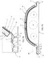
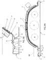
- FIG. 2Ais a schematized sectional front view of the system of FIG. 1 , taken along line 2 A- 2 A, illustrating simplified components to highlight layers on the mandrel tool and relative positions of the layers;
- FIG. 2Bis an enlarged view of a portion of the system of FIG. 2A , illustrating relative positioning of layers along a first edge flange of the mandrel tool that includes vacuum pressure sources or ports;
- FIG. 3Ais a partial view of the system of FIG. 2A , illustrating a lower breather sheet positioned adjacent a surface of the rigid tool;
- FIG. 3Bis an enlarged view of a portion of the system of FIG. 3A , illustrating relative positioning of the breather sheet along the first edge flange of the mandrel tool;
- FIG. 4Ais a partial view of the system of FIG. 2A , illustrating a lower vacuum bag over the lower breather sheet;
- FIG. 4Bis an enlarged view of a portion of the system of FIG. 4A , illustrating relative positioning of the lower vacuum bag along the first edge flange of the mandrel tool;
- FIG. 5Ais a partial view of the system of FIG. 2A , illustrating a wet peel ply over the first vacuum bag;
- FIG. 5Bis an enlarged view of a portion of the system of FIG. 5A , illustrating relative positioning of the wet peel ply along the first vacuum bag;
- FIG. 6Ais a partial view of the system of FIG. 2A , illustrating a honeycomb core part over the wet peel ply;
- FIG. 6Bis an enlarged view of a portion of the system of FIG. 6A , illustrating relative positioning of the honeycomb core part along the wet peel ply;
- FIG. 7Ais a partial view of the system of FIG. 2A , illustrating an upper breather sheet over the honeycomb core;
- FIG. 7Bis an enlarged view of a portion of the system of FIG. 7A , illustrating relative positioning of the upper breather sheet along the first edge flange of the mandrel tool;
- FIG. 8Ais a partial view of the system of FIG. 2A , illustrating an upper vacuum bag over the upper breather sheet;
- FIG. 8Bis an enlarged view of a portion of the system of FIG. 8A , illustrating relative positioning of the upper vacuum bag along the first edge flange of the mandrel tool;
- FIG. 9Ais a supplemented partial view of the system of FIG. 2A , omitting the upper vacuum bag and breather sheet and illustrating sculpting of the honeycomb core part by a machine tool;
- FIG. 9Bis an enlarged view of a portion of the system of FIG. 9A , illustrating application of vacuum pressure by the one of the vacuum pressure sources during the sculpting process;
- FIG. 10is a partial view of the system of FIG. 2A , illustrating removal of the sculpted honeycomb core, the peel ply, and the lower vacuum bag collectively following curing of core splice details and the peel ply and release of the vacuum pressure by the vacuum pressure source;
- FIG. 11is a partial view of the system of FIG. 10 , illustrating removal of the peel ply and the lower vacuum bag from the honeycomb core;
- FIG. 12illustrates at least a portion of the steps of an exemplary method for preparing a part using a rigid tool surface having a shape according to an embodiment of the present invention.
- An exemplary core partmay comprise a sheet of aviation honeycomb core such as that sold under the trademark PLASCORE® and labeled with the part identification PCGA-XR2 3003 Aluminum Honeycomb as of the priority date of the present disclosure.
- PLASCORE®a sheet of aviation honeycomb core
- PCGA-XR2 3003 Aluminum Honeycombas of the priority date of the present disclosure.
- One of ordinary skillwill appreciate that a variety of honeycomb cores and other core parts may be utilized within the scope of the present invention.
- a conventional sheet of aviation honeycomb coremay be utilized in aerospace applications for structural reinforcement and sound attenuation.
- the honeycomb core sheetmay be processed to form a final honeycomb core blanket, and may be incorporated between layers of skin to form a finished part.
- at least one layer of skine.g., perforated skin
- the perforated skinis, in turn, adhered and clamped to a tool surface to conform the honeycomb core sheet to a shape of the tool surface.
- skinmay comprise a plurality of plies generally conforming to the shape of the tool surface.
- the skinmay comprise thermoset composites or other composite materials known for use as skin in aerospace applications or the like.
- honeycomb core sheetexpands and contracts adjacent the tool surface in response to the heating cycles. Moreover, the tool surface itself will likewise expand and contract with the heating cycles. Because of the way in which the honeycomb core sheet is held against the tool surface, the honeycomb core sheet will often deform away from the tool surface in places, leading to errors in sculpting and otherwise processing the honeycomb core sheet for the final product. In an attempt to reduce these occurrences, tools comprising materials having low CTEs may be employed, with consequent increase in manufacturing costs. Nonetheless, such deformation and inconsistencies persist.
- Embodiments of the present inventionprovide an improved system and method for holding honeycomb core sheets (or other core parts) against a tool surface. These embodiments may permit improved maintenance of consistent three-dimensional shapes in the honeycomb core sheets throughout and following curing cycles, permit improved sculpting accuracy, and reduce costs of manufacture relative to existing systems. Moreover because the need to hold the core to the tool surface is temporary, embodiments of the present invention provide a means for removing the core from the tool with reduced or no damage to the core or the tool.
- the system 20may broadly comprise a mandrel tool 22 defining interior cavities 24 , 26 , 28 .
- the cavities 24 , 26 , 28may provide spaces through which air may be circulated, for example to assist in heating or cooling the tool 22 .
- the cavities 24 , 26 , 28may be omitted or otherwise configured within the scope of the present invention.
- the mandrel tool 22may comprise aluminum, steel (e.g., A36 steel), fiberglass, Invar (i.e., 64FeNi) and/or like rigid metals or composites.
- Embodiments of the present inventionpermit use of mandrel tools constructed of a variety of metals or composites—having a variety of coefficients of thermal expansion (CTEs)—through the use of improved systems and methods for preparing a honeycomb core and/or temporarily securing the honeycomb core to a mandrel tool for sculpting, as described in more detail below.
- CTEscoefficients of thermal expansion
- the tool 22includes a face-sheet or shaping surface 30 .
- the shaping surface 30may be constructed to form an outer mold line—such as the half-barrel shaped outer mold line of FIG. 1 —or another feature shape of a contoured part to be manufactured.
- the contoured parts manufactured with system 20may include three-dimensional characteristics such as height, depth, curvature, contours, features that intersect at angles up to and including ninety degrees, or features that include a space between them. Such contoured parts are often utilized in the manufacturing of aircraft.
- An example of a contoured part that may be manufactured in part by utilizing the system 20 and using methods disclosed hereinis a honeycomb core-reinforced nacelle wall having perforated skin.
- the tool 22generally supports the contoured core during manufacturing, sculpting and/or curing processes.
- the mandrel tool 22also includes first and second edge flanges 32 , 34 positioned along laterally opposite sides of the mandrel tool 22 .
- the edge flanges 32 , 34respectively extend longitudinally along the periphery of the mandrel tool 22 .
- third and fourth edge flangesmay be incorporated along longitudinal ends of a mandrel tool, extending laterally therealong, without departing from the spirit of the present invention.
- the edge flanges 32 , 34may be substantially planar and/or may extend orthogonally away from adjacent portions of the shaping surface 30 .
- the edge flange 32includes an inner portion 36 and an outer portion 38 , the inner portion 36 being nearer the shaping surface 30 .
- the inner portion 36includes a first vacuum port 40 covered by a mesh screen 42 .
- the first vacuum port 40serves as a source of vacuum pressure that can be transmitted through the mesh screen 42 to layers extending over the edge flange 32 and over the shaping surface 30 .
- the mesh screen 42may be substantially rigid and gas-permeable, permitting movement of the vacuum pressure therethrough while preventing bunching of overlying layers within the first vacuum port 40 .
- the mesh screen 42may comprise perforated aluminum, steel or the like without departing from the spirit of the present invention.
- the outer portion 38 of the edge flange 32includes a second vacuum port 44 covered by a mesh screen 46 .
- the second vacuum port 44serves as a source of vacuum pressure that can be transmitted through the mesh screen 46 to layers extending over the outer portion 38 of the edge flange 32 and over the shaping surface 30 .
- the mesh screen 46may be constructed substantially the same as the first mesh screen 42 outlined above.
- applying vacuum pressure to a spacerefers to reducing the pressure in that space.
- a mandrel toolis utilized in an ambient environment at atmospheric pressure
- the application of vacuum pressure to a space along or adjacent a surface of the toolmeans reducing pressure in that space below atmospheric pressure.
- pneumatic hosesare shown delivering vacuum pressures to the vacuum ports 40 , 44 .
- various structure and parts for applying vacuum pressuremay be implemented without departing from the scope of the present invention.
- the system 20also includes a gas-permeable breather sheet 48 (see FIGS. 3A-3B ) covering the shaping surface 30 and extending along the inner portion 36 of the edge flange 32 .
- the breather sheet 48may comprise non-woven polyester/polyamide felt cloth or the like of a porosity sufficient to permit movement of air across and through the breather sheet 48 and evenly-distributed application of vacuum pressure across adjacent gas-impermeable layers (discussed in more detail below).
- An exemplary breather clothis sold as of the priority date of the present disclosure under the trademark FIBRE GLAST® and part number 579.
- a breather sheetmay be supplemented or replaced with other structure and/or layers capable of distributing applied vacuum pressure across adjacent layers within the scope of the present invention.
- a shaping surfacemay comprise texturing such as grooves, grids or other patterns imprinted or etched therein, providing pathways for distributing applied vacuum pressure thereacross.
- a breather sheetmay be replaced by a silicone bag or the like embossed with such texturing or patterns for distributing applied vacuum pressure across overlying impermeable layers.
- the breather sheet 48is covered by a lower vacuum bag 50 (see FIGS. 4A-4B ) also extending along the inner portion 36 of the edge flange 32 .
- the vacuum bag 50is generally manufactured from a flexible and resilient material such as cured silicone rubber, nylon, polyurethane and/or fiber-reinforced versions of the foregoing (or other similar materials) that allows the vacuum bag 50 to adapt to curvatures and contours of the shaping surface 30 .
- the flexible material of the vacuum bag 50may be substantially or completely impermeable to the atmosphere and/or other gases.
- the flexible material of the vacuum bag 50is impermeable to atmosphere at a pressure differential of fifteen pounds per square inch (15 psi).
- the flexible material of the vacuum bag 50is impermeable to atmosphere at a pressure differential of one hundred pounds per square inch (100 psi) or greater.
- the vacuum bag 50may be reusable in that the bag may be used repeatedly to manufacture a plurality of contoured parts. It should also be noted that it is preferable for the vacuum bag 50 to be smoothly distributed across the shaping surface 30 to prevent bunching and sufficiently thin so as to minimize the effect of wrinkles or bunching in the bag 50 on the shape of the shaping surface 30 .
- the vacuum bag 50includes a perimeter portion 52 that extends along the inner portion 36 beyond the first vacuum port 40 to seal against the edge flange 32 .
- the vacuum bag 50also includes a perimeter portion 54 extends along and seals against the edge flange 34 .
- the perimeter portions 52 , 54may respectively be adhered to/sealed against the edge flanges 32 , 34 using mud or putty-like materials and/or double-sided adhesive tape or the like sufficient to form an air-tight seal for application of vacuum pressure from the first vacuum port 40 to the vacuum bag 50 .
- the system 20also includes a resin pre-impregnated ply or wet peel ply 56 (see FIGS. 5A-5B ) layered over the vacuum bag 50 .
- Wet peel ply 56may comprise a sheet of polyester peel ply support carrier pre-impregnated with resin (e.g., 48% nominal).
- An exemplary wet peel plyis sold under the trademark Hysol® EA 9895TM Peel Ply as of the priority date of the present disclosure.
- Hysol® EA 9895TM Peel Plyas of the priority date of the present disclosure.
- One of ordinary skillwill appreciate that other types of wet peel plies, double-sided adhesive tapes and/or the like may be used without departing from the spirit of the present invention.
- the system 20also includes a core part 58 (see FIGS. 6A-6B ).
- the core part 58preferably comprises a plurality of aviation honeycomb core sheets or details joined by core splice adhesive. More particularly, each piece of the core part 58 may include one or more interface surfaces 59 .
- Core splice adhesivemay be applied to one or both of adjacent interface surfaces 59 .
- Core splice adhesivemay comprise low density, epoxy based and expandable adhesives for splicing honeycomb cores, as is commonly known.
- adhesivesmay be used to join the sheets of honeycomb core without departing from the spirit of the present invention.
- the core part 58may also have a thickness T, which may be uniform throughout the core part 58 or local to a portion of the core part 58 .
- Each sheetmay be bent initially to a general approximation of a corresponding shape of the shaping surface 30 along which it will sit. However, one of ordinary skill will appreciate that such initial or preliminary bending may not be required within the scope of the present invention.
- the wet peel ply 56is preferably substantially co-extensive with the core part 58 , with the combination being layered over an area of the vacuum bag 50 above the shaping surface 30 .
- the illustrated wet peel ply 56 and core part 58do not extend over the edge flanges 32 , 34 as illustrated; however, it is foreseen that such extension may occur without departing from the spirit of the present invention.
- the system 20may also include an upper breather sheet 61 (see FIGS. 7A-7B ) and upper vacuum bag 62 (see FIGS. 8A-8B ).
- the upper breather sheet 61 and the upper vacuum bag 62cover the core part 58 , and may be respectively constructed similarly to corresponding lower breather sheet 48 and vacuum bag 50 .
- the upper vacuum bag 62includes a perimeter portion 64 that extends along the outer portion 38 of the edge flange 32 , beyond the first vacuum port 40 and the second vacuum port 44 , and seals against the edge flange 32 .
- the vacuum bag 62also includes a perimeter portion 66 that extends along and seals against the edge flange 34 and/or a top surface of the vacuum bag 50 .
- the perimeter portions 64 , 66may respectively be adhered to/sealed using mud or putty-like materials and/or double-sided adhesive tape or the like sufficient to form an air-tight seal for application of vacuum pressure from the second vacuum port 44 to the upper vacuum bag 62 .
- sealing along perimeter portions of a vacuum bagmay be achieved by a number of structures, fasteners, adhesives or the like.
- a seal about the mandrel tool that incorporates a vacuum port thereinpreferably extends about an entirety of a perimeter of a vacuum bag, thereby preventing leakage of the vacuum pressure from (or ventilation of) the space underneath the vacuum bag. It is foreseen that such sealing may extend along longitudinal end portions of a mandrel in substantially the same manner as described above without departing from the spirit of the present invention.
- the vacuum bags 50 , 62seal against the edge flanges 32 , 34 (and/or an underlying layer) and other surfaces of the tool 22 along the periphery of the bags 50 , 62 .
- FIG. 12At least a portion of the steps of a method 1200 for manufacturing a core part using the system 20 in accordance with various embodiments of the present invention is listed in FIG. 12 .
- the stepsmay be performed in the order as shown in FIG. 12 , or they may be performed in a different order. Further, some steps may be performed concurrently as opposed to sequentially. In addition, some steps may be omitted. Still further, embodiments of the present invention may be performed using systems other than system 20 without departing from the spirit of the present invention.
- a lower breather sheetmay be applied over a shaping surface of a mandrel tool. More particularly, a lower side of the breather sheet may be placed adjacent or against the shaping surface.
- a lower vacuum bagmay be applied over the lower breather sheet and sealed to the mandrel tool. More particularly, a lower side of the vacuum bag may be placed adjacent or against an upper side of the lower breather sheet. Perimeter portions of the vacuum bag may be sealed against perimeter portions of the mandrel tool using mud or putty-like materials and/or double-sided adhesive tape or the like sufficient to form an air-tight seal for application of vacuum pressure under the lower vacuum bag.
- vacuum pressuremay be applied to the lower side of the lower vacuum bag.
- the vacuum pressuremay suction the vacuum bag (and, consequently, the underlying lower breather sheet) against the shape of the shaping surface of the mandrel tool.
- the vacuum pressuremay be applied by a first vacuum port positioned along the mandrel tool inside the boundary seal around the lower vacuum sheet. The vacuum pressure may be maintained until step 1211 discussed below.
- a wet peel plymay be applied over an area of the lower vacuum bag. More particularly, a lower side of the wet peel ply may be applied over the upper side of the lower vacuum bag across an area roughly co-extensive with an expected span or coverage of core details discussed in more detail below.
- core detailse.g., pre-formed sheets of aviation honeycomb core
- core splice adhesivemay be applied to interface surfaces of adjacent sheets of honeycomb core, and the sheets may be lined up and pressed together at the interface surfaces atop the wet peel ply.
- an upper breather sheet and upper vacuum bagare applied over the assembled sheets of honeycomb core.
- the upper vacuum baggenerally extends outward along at least one perimeter portion of the mandrel tool beyond the corresponding perimeter portion of the lower vacuum bag.
- the perimeter portion of the upper vacuum bag that extends outward beyond a corresponding perimeter portion of the lower vacuum bagmay be sealed against the mandrel tool.
- This perimeter portion of the upper vacuum bagmay be in fluid communication with a second vacuum port of the mandrel tool.
- the remaining perimeter portions of the upper vacuum bagmay optionally be sealed against the mandrel tool and/or against the lower vacuum bag or other gas-impermeable underlying layer.
- gasmay be evacuated from beneath the upper vacuum bag. More particularly, the second vacuum port may apply vacuum pressure to the lower side of the upper vacuum bag to press it against the core details and, in turn, to press the core details against the wet peel ply. The vacuum pressure may be maintained against the upper vacuum bag until step 1209 .
- the assemblymay be placed in an autoclave or otherwise heated to cure the wet peel ply and the core splice adhesive.
- the autoclavemay be adapted for curing wet peel ply and/or core splice adhesives, as is generally known in the art.
- heating or other meansmay be utilized to cure the wet peel play and/or core splice adhesive without departing from the spirit of the present invention.
- the upper vacuum bag and upper breather sheetmay be removed from the cured core detail blanket. More particularly, the vacuum pressure from the second vacuum port may be released after the heating step to ventilate the underside of the upper vacuum bag. Subsequently, the upper vacuum bag and upper breather sheet may be removed.
- the core detail blanketmay be sculpted using a machine tool. More particularly, the machine tool may be applied across a top side of the core detail blanket to reduce the thickness thereof and move the core detail blanket toward a finished three-dimensional shape and thickness, as is commonly known in the art.
- the lower vacuum bagmay be ventilated and the core detail blanket may be removed from the mandrel tool. More particularly, the vacuum pressure from the first vacuum port may be released and the underside of the lower vacuum bag ventilated to permit removal of the core detail blanket with cured wet peel ply and lower vacuum bag attached.
- the wet peel ply(with lower vacuum bag attached) may be peeled away from the core detail blanket.
- Embodiments of the present inventiontherefore provide an improved system and method for holding honeycomb core sheets (or other core parts) against a tool surface. These embodiments may permit improved maintenance of consistent three-dimensional shapes in the honeycomb core sheets throughout and following curing cycles, permit improved sculpting accuracy, and reduce costs of manufacture relative to existing systems. Moreover, preferred embodiments permit the core blanket to be spliced and sculpted before being attached to skin or carbon face-sheet(s) having low CTEs, thus reducing the likelihood of node bond failure and cell wall tears that might otherwise occur due to or during cool-down due to CTE mismatch stresses.
Landscapes
- Engineering & Computer Science (AREA)
- Mechanical Engineering (AREA)
- Chemical & Material Sciences (AREA)
- Composite Materials (AREA)
- Casting Or Compression Moulding Of Plastics Or The Like (AREA)
Abstract
Description
Claims (17)
Priority Applications (4)
| Application Number | Priority Date | Filing Date | Title |
|---|---|---|---|
| US16/551,913US11511502B2 (en) | 2019-08-27 | 2019-08-27 | Method for securing core to tool during machining |
| EP20856152.2AEP4021710A4 (en) | 2019-08-27 | 2020-07-31 | Method for securing core to tool during machining |
| PCT/US2020/044381WO2021040960A1 (en) | 2019-08-27 | 2020-07-31 | Method for securing core to tool during machining |
| US17/961,395US20230033757A1 (en) | 2019-08-27 | 2022-10-06 | Method for securing core to tool during machining |
Applications Claiming Priority (1)
| Application Number | Priority Date | Filing Date | Title |
|---|---|---|---|
| US16/551,913US11511502B2 (en) | 2019-08-27 | 2019-08-27 | Method for securing core to tool during machining |
Related Child Applications (1)
| Application Number | Title | Priority Date | Filing Date |
|---|---|---|---|
| US17/961,395DivisionUS20230033757A1 (en) | 2019-08-27 | 2022-10-06 | Method for securing core to tool during machining |
Publications (2)
| Publication Number | Publication Date |
|---|---|
| US20210060874A1 US20210060874A1 (en) | 2021-03-04 |
| US11511502B2true US11511502B2 (en) | 2022-11-29 |
Family
ID=74681220
Family Applications (2)
| Application Number | Title | Priority Date | Filing Date |
|---|---|---|---|
| US16/551,913Active2040-01-30US11511502B2 (en) | 2019-08-27 | 2019-08-27 | Method for securing core to tool during machining |
| US17/961,395PendingUS20230033757A1 (en) | 2019-08-27 | 2022-10-06 | Method for securing core to tool during machining |
Family Applications After (1)
| Application Number | Title | Priority Date | Filing Date |
|---|---|---|---|
| US17/961,395PendingUS20230033757A1 (en) | 2019-08-27 | 2022-10-06 | Method for securing core to tool during machining |
Country Status (3)
| Country | Link |
|---|---|
| US (2) | US11511502B2 (en) |
| EP (1) | EP4021710A4 (en) |
| WO (1) | WO2021040960A1 (en) |
Families Citing this family (1)
| Publication number | Priority date | Publication date | Assignee | Title |
|---|---|---|---|---|
| CN114379121B (en)* | 2021-11-24 | 2023-07-07 | 中国南方航空股份有限公司 | Repair process of honeycomb sandwich structure at the front part of the engine reverse thrust translation door inner cylinder |
Citations (32)
| Publication number | Priority date | Publication date | Assignee | Title |
|---|---|---|---|---|
| US4065340A (en)* | 1977-04-28 | 1977-12-27 | The United States Of America As Represented By The National Aeronautics And Space Administration | Composite lamination method |
| US4942013A (en)* | 1989-03-27 | 1990-07-17 | Mcdonnell Douglas Corporation | Vacuum resin impregnation process |
| US5242523A (en)* | 1992-05-14 | 1993-09-07 | The Boeing Company | Caul and method for bonding and curing intricate composite structures |
| US5403537A (en)* | 1993-09-14 | 1995-04-04 | Martin Marietta Corporation | Method for forming composite structures |
| US5780074A (en) | 1995-10-16 | 1998-07-14 | The Boeing Company | Apparatus for shaping honeycomb core |
| US6173807B1 (en) | 1998-04-13 | 2001-01-16 | The Boeing Company | Engine nacelle acoustic panel with integral wedge fairings and an integral forward ring |
| US20020022422A1 (en)* | 1999-12-07 | 2002-02-21 | Waldrop John C. | Double bag vacuum infusion process and system for low cost, advanced composite fabrication |
| US6620369B1 (en)* | 2000-02-09 | 2003-09-16 | Northrop Grumman Corporation | Net molding of resin composite parts |
| US6759002B1 (en)* | 1996-04-08 | 2004-07-06 | The Boeing Company | Method for making a composite |
| US20040219244A1 (en)* | 2001-08-22 | 2004-11-04 | Jurgen Filsinger | Method and device for producing fiber-reinforced components by an injection method |
| US20060027314A1 (en)* | 2004-08-09 | 2006-02-09 | Structural Polymer Systems | Mould |
| US20060172111A1 (en)* | 2005-02-02 | 2006-08-03 | Polus Jeffrey E | Low temperature, vacuum cure fabrication process for large, honeycomb core stiffened composite structures |
| US20060249868A1 (en)* | 2005-05-03 | 2006-11-09 | The Boeing Company | Method of manufacturing curved composite structural elements |
| US20070149080A1 (en)* | 2004-03-30 | 2007-06-28 | Nobuo Asahara | Preform, frp, and processes for producing these |
| US20070251641A1 (en)* | 2006-04-28 | 2007-11-01 | Airbus Espana, S.L. | Tool and process for manufacturing long pieces of composite material |
| US20080124520A1 (en)* | 2006-11-24 | 2008-05-29 | Honda Motor Co., Ltd. | Method for producing fiber-reinforced composite member with connecting holes, and structural member for aircrafts constituted by such composite members |
| US20080210372A1 (en)* | 2007-03-01 | 2008-09-04 | Cumings Robert C | Composite article debulking process |
| US20090166935A1 (en) | 2006-07-06 | 2009-07-02 | Torben Jacob | Method for Producing a Fiber Composite Component for Aerospace |
| US8251174B2 (en) | 2010-03-26 | 2012-08-28 | Spirit Aerosystems, Inc. | Method for bonding honeycomb cores |
| US20150107775A1 (en)* | 2013-10-22 | 2015-04-23 | The Boeing Company | Vacuum Bag Sealing System and Method for Composite Parts |
| US20170173898A1 (en) | 2014-04-02 | 2017-06-22 | Magna International Inc. | End of arm tooling |
| US20170252982A1 (en) | 2016-03-04 | 2017-09-07 | The Boeing Company | Dynamic forming tools for composite parts |
| US9937672B2 (en)* | 2009-05-15 | 2018-04-10 | The Boeing Company | Cure tool with integrated edge breather and method of making the same |
| US20180194085A1 (en)* | 2014-11-19 | 2018-07-12 | Bae Systems Plc | Object production |
| US20180257272A1 (en)* | 2015-11-26 | 2018-09-13 | Bayerische Motoren Werke Aktiengesellschaft | Production of Textile Composite Material Preforms |
| US20180339413A1 (en) | 2017-05-26 | 2018-11-29 | The Boeing Company | Flexible vacuum securement of objects to complex surfaces |
| US20190016067A1 (en)* | 2016-01-08 | 2019-01-17 | Teijin Limited | Method for Producing Fiber-Reinforced Resin Shaped Product |
| US10232532B1 (en)* | 2006-02-02 | 2019-03-19 | The Boeing Company | Method for fabricating tapered thermoplastic composite parts |
| US20190168481A1 (en)* | 2017-12-01 | 2019-06-06 | The Boeing Company | Methods for Making Composite Parts from Stacked Partially Cured Sublaminate Units |
| US20190240949A1 (en)* | 2018-02-02 | 2019-08-08 | The Boeing Company | Composite Sandwich Panels with Over-Crushed Edge Regions |
| US20190315075A1 (en)* | 2018-04-11 | 2019-10-17 | Rolls-Royce Plc | A method |
| US20200016880A1 (en)* | 2018-07-16 | 2020-01-16 | Bell Helicopter Textron Inc. | Methods for forming composite structures |
Family Cites Families (9)
| Publication number | Priority date | Publication date | Assignee | Title |
|---|---|---|---|---|
| US5318422A (en)* | 1992-11-05 | 1994-06-07 | Erland Robert K | Vacuum bag molding apparatus with channel and spline edge-seal |
| US6739861B2 (en)* | 2001-11-26 | 2004-05-25 | Sikorsky Aircraft Corporation | High pressure co-cure of lightweight core composite article utilizing a core having a plurality of protruding pins |
| EP1897680B1 (en) | 2006-09-07 | 2008-11-12 | Euro-Composites S.A. | Manufacturing process of a honeycomb sandwich panel |
| DE102009010621B3 (en)* | 2009-02-12 | 2010-12-02 | Mt Aerospace Ag | Method for stabilization of honeycomb core for sandwich composite structures made of fiber-reinforced composites, involves pre-fixing honeycomb core at open-cell side on manufacturing equipment with textured surface |
| US9676148B2 (en)* | 2014-08-04 | 2017-06-13 | Spirit Aerosystems, Inc. | System and method for manufacturing and testing composite acoustic panels |
| KR101821695B1 (en)* | 2016-01-04 | 2018-03-08 | (주)터보마린 | Frp boat and a manufacturing infusion metehod thereof |
| US10335983B2 (en)* | 2016-07-22 | 2019-07-02 | Hall Labs Llc | Out-of-autoclave compression molding |
| US10183421B2 (en)* | 2016-09-16 | 2019-01-22 | General Electric Company | Molding method |
| EP3670169B1 (en)* | 2018-12-21 | 2022-10-05 | Siemens Gamesa Renewable Energy A/S | A vacuum assisted resin transfer molding method |
- 2019
- 2019-08-27USUS16/551,913patent/US11511502B2/enactiveActive
- 2020
- 2020-07-31EPEP20856152.2Apatent/EP4021710A4/enactivePending
- 2020-07-31WOPCT/US2020/044381patent/WO2021040960A1/ennot_activeCeased
- 2022
- 2022-10-06USUS17/961,395patent/US20230033757A1/enactivePending
Patent Citations (40)
| Publication number | Priority date | Publication date | Assignee | Title |
|---|---|---|---|---|
| US4065340A (en)* | 1977-04-28 | 1977-12-27 | The United States Of America As Represented By The National Aeronautics And Space Administration | Composite lamination method |
| US4942013A (en)* | 1989-03-27 | 1990-07-17 | Mcdonnell Douglas Corporation | Vacuum resin impregnation process |
| US5242523A (en)* | 1992-05-14 | 1993-09-07 | The Boeing Company | Caul and method for bonding and curing intricate composite structures |
| US5403537A (en)* | 1993-09-14 | 1995-04-04 | Martin Marietta Corporation | Method for forming composite structures |
| US5780074A (en) | 1995-10-16 | 1998-07-14 | The Boeing Company | Apparatus for shaping honeycomb core |
| US6759002B1 (en)* | 1996-04-08 | 2004-07-06 | The Boeing Company | Method for making a composite |
| US6173807B1 (en) | 1998-04-13 | 2001-01-16 | The Boeing Company | Engine nacelle acoustic panel with integral wedge fairings and an integral forward ring |
| US20020022422A1 (en)* | 1999-12-07 | 2002-02-21 | Waldrop John C. | Double bag vacuum infusion process and system for low cost, advanced composite fabrication |
| US7413694B2 (en)* | 1999-12-07 | 2008-08-19 | The Boeing Company | Double bag vacuum infusion process |
| US6620369B1 (en)* | 2000-02-09 | 2003-09-16 | Northrop Grumman Corporation | Net molding of resin composite parts |
| US20040219244A1 (en)* | 2001-08-22 | 2004-11-04 | Jurgen Filsinger | Method and device for producing fiber-reinforced components by an injection method |
| US8192662B2 (en)* | 2004-03-30 | 2012-06-05 | Toray Industries, Inc. | Processes for producing perform and FRP |
| US20090301641A1 (en)* | 2004-03-30 | 2009-12-10 | Nobuo Asahara | Processes for producing perform and FRP |
| US20070149080A1 (en)* | 2004-03-30 | 2007-06-28 | Nobuo Asahara | Preform, frp, and processes for producing these |
| US20060027314A1 (en)* | 2004-08-09 | 2006-02-09 | Structural Polymer Systems | Mould |
| US20060172111A1 (en)* | 2005-02-02 | 2006-08-03 | Polus Jeffrey E | Low temperature, vacuum cure fabrication process for large, honeycomb core stiffened composite structures |
| US20060249868A1 (en)* | 2005-05-03 | 2006-11-09 | The Boeing Company | Method of manufacturing curved composite structural elements |
| US8632653B2 (en)* | 2005-05-03 | 2014-01-21 | The Boeing Company | Method of manufacturing curved composite structural elements |
| US20140069576A1 (en)* | 2005-05-03 | 2014-03-13 | The Boeing Company | Method of manufacturing curved composite structural elements |
| US9630390B2 (en)* | 2005-05-03 | 2017-04-25 | The Boeing Company | Method of manufacturing curved composite structural elements |
| US10232532B1 (en)* | 2006-02-02 | 2019-03-19 | The Boeing Company | Method for fabricating tapered thermoplastic composite parts |
| US20070251641A1 (en)* | 2006-04-28 | 2007-11-01 | Airbus Espana, S.L. | Tool and process for manufacturing long pieces of composite material |
| US20090166935A1 (en) | 2006-07-06 | 2009-07-02 | Torben Jacob | Method for Producing a Fiber Composite Component for Aerospace |
| US20080124520A1 (en)* | 2006-11-24 | 2008-05-29 | Honda Motor Co., Ltd. | Method for producing fiber-reinforced composite member with connecting holes, and structural member for aircrafts constituted by such composite members |
| US20080210372A1 (en)* | 2007-03-01 | 2008-09-04 | Cumings Robert C | Composite article debulking process |
| US9937672B2 (en)* | 2009-05-15 | 2018-04-10 | The Boeing Company | Cure tool with integrated edge breather and method of making the same |
| US8251174B2 (en) | 2010-03-26 | 2012-08-28 | Spirit Aerosystems, Inc. | Method for bonding honeycomb cores |
| US20150107775A1 (en)* | 2013-10-22 | 2015-04-23 | The Boeing Company | Vacuum Bag Sealing System and Method for Composite Parts |
| US20170173898A1 (en) | 2014-04-02 | 2017-06-22 | Magna International Inc. | End of arm tooling |
| US20180194085A1 (en)* | 2014-11-19 | 2018-07-12 | Bae Systems Plc | Object production |
| US10647070B2 (en)* | 2014-11-19 | 2020-05-12 | Bae Systems Plc | Object production |
| US20180257272A1 (en)* | 2015-11-26 | 2018-09-13 | Bayerische Motoren Werke Aktiengesellschaft | Production of Textile Composite Material Preforms |
| US10919193B2 (en)* | 2015-11-26 | 2021-02-16 | Bayerische Motoren Werke Aktiengesellschaft | Production of textile composite material preforms |
| US20190016067A1 (en)* | 2016-01-08 | 2019-01-17 | Teijin Limited | Method for Producing Fiber-Reinforced Resin Shaped Product |
| US20170252982A1 (en) | 2016-03-04 | 2017-09-07 | The Boeing Company | Dynamic forming tools for composite parts |
| US20180339413A1 (en) | 2017-05-26 | 2018-11-29 | The Boeing Company | Flexible vacuum securement of objects to complex surfaces |
| US20190168481A1 (en)* | 2017-12-01 | 2019-06-06 | The Boeing Company | Methods for Making Composite Parts from Stacked Partially Cured Sublaminate Units |
| US20190240949A1 (en)* | 2018-02-02 | 2019-08-08 | The Boeing Company | Composite Sandwich Panels with Over-Crushed Edge Regions |
| US20190315075A1 (en)* | 2018-04-11 | 2019-10-17 | Rolls-Royce Plc | A method |
| US20200016880A1 (en)* | 2018-07-16 | 2020-01-16 | Bell Helicopter Textron Inc. | Methods for forming composite structures |
Non-Patent Citations (1)
| Title |
|---|
| International Search Report and Written Opinion, dated Nov. 11, 2020 for PCT Appln. No. PCT/US2020/044381; Filed Jul. 31, 2020 and all references cited therein. |
Also Published As
| Publication number | Publication date |
|---|---|
| EP4021710A1 (en) | 2022-07-06 |
| WO2021040960A1 (en) | 2021-03-04 |
| US20210060874A1 (en) | 2021-03-04 |
| US20230033757A1 (en) | 2023-02-02 |
| EP4021710A4 (en) | 2023-09-06 |
Similar Documents
| Publication | Publication Date | Title |
|---|---|---|
| US7228611B2 (en) | Method of transferring large uncured composite laminates | |
| CN105904740B (en) | A kind of integral manufacturing method of composite material light continuous fiber grid | |
| US8333864B2 (en) | Compaction of prepreg plies on composite laminate structures | |
| EP2886311B1 (en) | Three-dimensional reuseable curing caul for use in curing integrated composite components and method of making the same | |
| US7097731B2 (en) | Method of manufacturing a hollow section, grid stiffened panel | |
| US9925697B2 (en) | Method for bladder repair during composite part curing | |
| US10549492B2 (en) | Method for manufacturing carbon fiber panels stiffened with omega stringers | |
| US10052828B2 (en) | Supporting profiled element, method for producing a supporting profiled element, and use of said supporting profiled element in a method for producing a reinforced vehicle fuselage component | |
| US10766212B2 (en) | Method and apparatus for forming radius filler kits | |
| JPWO2019171683A1 (en) | Method for forming honeycomb sandwich composite material and jig used therefor | |
| US20230033757A1 (en) | Method for securing core to tool during machining | |
| US8974623B2 (en) | Method and a placement tool for the manufacture of a non-crimp fabric | |
| US8715560B2 (en) | Method to control thickness in composite parts cured on closed angle tool | |
| US20210094240A1 (en) | Method and apparatus for fabrication of composite tooling | |
| US9802382B2 (en) | Honeycomb structural body and method of manufacturing honeycomb structural body | |
| US11981839B2 (en) | Method and apparatus for fabrication of composite tooling | |
| EP4163076B1 (en) | Rapid tooling layup mandrel and method of moulding a part | |
| US9511520B1 (en) | Method, apparatus and device for preventing vacuum bag wrinkling | |
| US20050104259A1 (en) | Method of manufacturing composite sandwich structures | |
| CN115195152A (en) | Apparatus and method for processing composite structures | |
| US11554558B2 (en) | Tool for manufacturing a composite component | |
| US11826904B2 (en) | End effector, system and method for picking up and placing an object | |
| US12285920B2 (en) | Method and apparatus for fabrication of composite tooling | |
| GB2404612A (en) | Sectional mould | |
| JP2003103670A (en) | Honeycomb panel molding method |
Legal Events
| Date | Code | Title | Description |
|---|---|---|---|
| AS | Assignment | Owner name:SPIRIT AEROSYSTEMS, INC., KANSAS Free format text:ASSIGNMENT OF ASSIGNORS INTEREST;ASSIGNOR:WADSWORTH, MARK ANTHONY;REEL/FRAME:050177/0456 Effective date:20190826 | |
| FEPP | Fee payment procedure | Free format text:ENTITY STATUS SET TO UNDISCOUNTED (ORIGINAL EVENT CODE: BIG.); ENTITY STATUS OF PATENT OWNER: LARGE ENTITY | |
| AS | Assignment | Owner name:BANK OF AMERICA, N.A., AS COLLATERAL AGENT, NORTH CAROLINA Free format text:NOTICE OF GRANT OF SECURITY INTEREST IN PATENTS;ASSIGNOR:SPIRIT AEROSYSTEMS, INC.;REEL/FRAME:052004/0929 Effective date:20200224 | |
| STPP | Information on status: patent application and granting procedure in general | Free format text:DOCKETED NEW CASE - READY FOR EXAMINATION | |
| AS | Assignment | Owner name:THE BANK OF NEW YORK MELLON TRUST COMPANY, N.A., ILLINOIS Free format text:SECURITY INTEREST;ASSIGNOR:SPIRIT AEROSYSTEMS, INC.;REEL/FRAME:052433/0843 Effective date:20200417 | |
| AS | Assignment | Owner name:BANK OF AMERICA, N.A., NORTH CAROLINA Free format text:SECURITY INTEREST;ASSIGNOR:SPIRIT AEROSYSTEMS, INC.;REEL/FRAME:053983/0350 Effective date:20201005 Owner name:THE BANK OF NEW YORK MELLON TRUST COMPANY, N.A., ILLINOIS Free format text:SECURITY INTEREST;ASSIGNOR:SPIRIT AEROSYSTEMS, INC.;REEL/FRAME:053993/0569 Effective date:20201005 | |
| AS | Assignment | Owner name:SPIRIT AEROSYSTEMS, INC., KANSAS Free format text:RELEASE BY SECURED PARTY;ASSIGNOR:BANK OF AMERICA, N.A.;REEL/FRAME:054230/0578 Effective date:20201005 | |
| STPP | Information on status: patent application and granting procedure in general | Free format text:NON FINAL ACTION MAILED | |
| STPP | Information on status: patent application and granting procedure in general | Free format text:RESPONSE TO NON-FINAL OFFICE ACTION ENTERED AND FORWARDED TO EXAMINER | |
| STPP | Information on status: patent application and granting procedure in general | Free format text:FINAL REJECTION MAILED | |
| STPP | Information on status: patent application and granting procedure in general | Free format text:DOCKETED NEW CASE - READY FOR EXAMINATION | |
| STPP | Information on status: patent application and granting procedure in general | Free format text:NOTICE OF ALLOWANCE MAILED -- APPLICATION RECEIVED IN OFFICE OF PUBLICATIONS | |
| STPP | Information on status: patent application and granting procedure in general | Free format text:PUBLICATIONS -- ISSUE FEE PAYMENT VERIFIED | |
| STCF | Information on status: patent grant | Free format text:PATENTED CASE | |
| AS | Assignment | Owner name:SPIRIT AEROSYSTEMS, INC., KANSAS Free format text:RELEASE BY SECURED PARTY;ASSIGNOR:THE BANK OF NEW YORK MELLON TRUST COMPANY, N.A., AS COLLATERAL AGENT;REEL/FRAME:061995/0281 Effective date:20221123 Owner name:THE BANK OF NEW YORK MELLON TRUST COMPANY, N.A., ILLINOIS Free format text:NOTICE OF GRANT OF SECURITY INTEREST IN PATENTS;ASSIGNOR:SPIRIT AEROSYSTEMS, INC.;REEL/FRAME:061993/0847 Effective date:20221123 | |
| AS | Assignment | Owner name:THE BANK OF NEW YORK MELLON TRUST COMPANY, N.A., AS COLLATERAL AGENT, ILLINOIS Free format text:SECURITY AGREEMENT (SECOND LIEN NOTES);ASSIGNOR:SPIRIT AEROSYSTEMS, INC.;REEL/FRAME:065659/0585 Effective date:20231121 | |
| AS | Assignment | Owner name:SPIRIT AEROSYSTEMS NORTH CAROLINA, INC., NORTH CAROLINA Free format text:RELEASE BY SECURED PARTY;ASSIGNOR:THE BANK OF NEW YORK MELLON TRUST COMPANY, N.A.;REEL/FRAME:065772/0456 Effective date:20231201 Owner name:SPIRIT AEROSYSTEMS HOLDINGS, INC., KANSAS Free format text:RELEASE BY SECURED PARTY;ASSIGNOR:THE BANK OF NEW YORK MELLON TRUST COMPANY, N.A.;REEL/FRAME:065772/0456 Effective date:20231201 Owner name:SPIRIT AEROSYSTEMS, INC., KANSAS Free format text:RELEASE BY SECURED PARTY;ASSIGNOR:THE BANK OF NEW YORK MELLON TRUST COMPANY, N.A.;REEL/FRAME:065772/0456 Effective date:20231201 | |
| AS | Assignment | Owner name:MORGAN STANLEY SENIOR FUNDING, INC., MARYLAND Free format text:SECURITY AGREEMENT;ASSIGNOR:SPIRIT AEROSYSTEMS, INC.;REEL/FRAME:068217/0456 Effective date:20240630 |