US11511289B2 - Rotary full circle nozzles and deflectors - Google Patents
Rotary full circle nozzles and deflectorsDownload PDFInfo
- Publication number
- US11511289B2 US11511289B2US15/649,072US201715649072AUS11511289B2US 11511289 B2US11511289 B2US 11511289B2US 201715649072 AUS201715649072 AUS 201715649072AUS 11511289 B2US11511289 B2US 11511289B2
- Authority
- US
- United States
- Prior art keywords
- nozzle
- flow
- deflector
- inlet
- radius
- Prior art date
- Legal status (The legal status is an assumption and is not a legal conclusion. Google has not performed a legal analysis and makes no representation as to the accuracy of the status listed.)
- Active, expires
Links
Images


Classifications
- B—PERFORMING OPERATIONS; TRANSPORTING
- B05—SPRAYING OR ATOMISING IN GENERAL; APPLYING FLUENT MATERIALS TO SURFACES, IN GENERAL
- B05B—SPRAYING APPARATUS; ATOMISING APPARATUS; NOZZLES
- B05B1/00—Nozzles, spray heads or other outlets, with or without auxiliary devices such as valves, heating means
- B05B1/26—Nozzles, spray heads or other outlets, with or without auxiliary devices such as valves, heating means with means for mechanically breaking-up or deflecting the jet after discharge, e.g. with fixed deflectors; Breaking-up the discharged liquid or other fluent material by impinging jets
- B05B1/262—Nozzles, spray heads or other outlets, with or without auxiliary devices such as valves, heating means with means for mechanically breaking-up or deflecting the jet after discharge, e.g. with fixed deflectors; Breaking-up the discharged liquid or other fluent material by impinging jets with fixed deflectors
- B05B1/265—Nozzles, spray heads or other outlets, with or without auxiliary devices such as valves, heating means with means for mechanically breaking-up or deflecting the jet after discharge, e.g. with fixed deflectors; Breaking-up the discharged liquid or other fluent material by impinging jets with fixed deflectors the liquid or other fluent material being symmetrically deflected about the axis of the nozzle
- B—PERFORMING OPERATIONS; TRANSPORTING
- B05—SPRAYING OR ATOMISING IN GENERAL; APPLYING FLUENT MATERIALS TO SURFACES, IN GENERAL
- B05B—SPRAYING APPARATUS; ATOMISING APPARATUS; NOZZLES
- B05B1/00—Nozzles, spray heads or other outlets, with or without auxiliary devices such as valves, heating means
- B05B1/30—Nozzles, spray heads or other outlets, with or without auxiliary devices such as valves, heating means designed to control volume of flow, e.g. with adjustable passages
- B05B1/3033—Nozzles, spray heads or other outlets, with or without auxiliary devices such as valves, heating means designed to control volume of flow, e.g. with adjustable passages the control being effected by relative coaxial longitudinal movement of the controlling element and the spray head
- B05B1/304—Nozzles, spray heads or other outlets, with or without auxiliary devices such as valves, heating means designed to control volume of flow, e.g. with adjustable passages the control being effected by relative coaxial longitudinal movement of the controlling element and the spray head the controlling element being a lift valve
- B—PERFORMING OPERATIONS; TRANSPORTING
- B05—SPRAYING OR ATOMISING IN GENERAL; APPLYING FLUENT MATERIALS TO SURFACES, IN GENERAL
- B05B—SPRAYING APPARATUS; ATOMISING APPARATUS; NOZZLES
- B05B3/00—Spraying or sprinkling apparatus with moving outlet elements or moving deflecting elements
- B05B3/003—Spraying or sprinkling apparatus with moving outlet elements or moving deflecting elements with braking means, e.g. friction rings designed to provide a substantially constant revolution speed
- B—PERFORMING OPERATIONS; TRANSPORTING
- B05—SPRAYING OR ATOMISING IN GENERAL; APPLYING FLUENT MATERIALS TO SURFACES, IN GENERAL
- B05B—SPRAYING APPARATUS; ATOMISING APPARATUS; NOZZLES
- B05B3/00—Spraying or sprinkling apparatus with moving outlet elements or moving deflecting elements
- B05B3/02—Spraying or sprinkling apparatus with moving outlet elements or moving deflecting elements with rotating elements
- B05B3/021—Spraying or sprinkling apparatus with moving outlet elements or moving deflecting elements with rotating elements with means for regulating the jet relative to the horizontal angular position of the nozzle, e.g. for spraying non-circular areas by changing the elevation of the nozzle or by varying the nozzle flow-rate
- B—PERFORMING OPERATIONS; TRANSPORTING
- B05—SPRAYING OR ATOMISING IN GENERAL; APPLYING FLUENT MATERIALS TO SURFACES, IN GENERAL
- B05B—SPRAYING APPARATUS; ATOMISING APPARATUS; NOZZLES
- B05B3/00—Spraying or sprinkling apparatus with moving outlet elements or moving deflecting elements
- B05B3/02—Spraying or sprinkling apparatus with moving outlet elements or moving deflecting elements with rotating elements
- B05B3/04—Spraying or sprinkling apparatus with moving outlet elements or moving deflecting elements with rotating elements driven by the liquid or other fluent material discharged, e.g. the liquid actuating a motor before passing to the outlet
- B05B3/0417—Spraying or sprinkling apparatus with moving outlet elements or moving deflecting elements with rotating elements driven by the liquid or other fluent material discharged, e.g. the liquid actuating a motor before passing to the outlet comprising a liquid driven rotor, e.g. a turbine
- B05B3/0425—Spraying or sprinkling apparatus with moving outlet elements or moving deflecting elements with rotating elements driven by the liquid or other fluent material discharged, e.g. the liquid actuating a motor before passing to the outlet comprising a liquid driven rotor, e.g. a turbine actuated downstream of the outlet elements
- B05B3/0426—Spraying or sprinkling apparatus with moving outlet elements or moving deflecting elements with rotating elements driven by the liquid or other fluent material discharged, e.g. the liquid actuating a motor before passing to the outlet comprising a liquid driven rotor, e.g. a turbine actuated downstream of the outlet elements the liquid driven rotor being a deflecting rotating element
- B05B3/0486—
- B—PERFORMING OPERATIONS; TRANSPORTING
- B05—SPRAYING OR ATOMISING IN GENERAL; APPLYING FLUENT MATERIALS TO SURFACES, IN GENERAL
- B05B—SPRAYING APPARATUS; ATOMISING APPARATUS; NOZZLES
- B05B15/00—Details of spraying plant or spraying apparatus not otherwise provided for; Accessories
- B05B15/70—Arrangements for moving spray heads automatically to or from the working position
- B05B15/72—Arrangements for moving spray heads automatically to or from the working position using hydraulic or pneumatic means
- B05B15/74—Arrangements for moving spray heads automatically to or from the working position using hydraulic or pneumatic means driven by the discharged fluid
Definitions
- the inventionrelates to irrigation nozzles and deflectors and, more particularly, to a rotary nozzle for distribution of water in a full circle irrigation pattern.
- Nozzlesare commonly used for the irrigation of landscape and vegetation.
- various types of nozzlesare used to distribute water over a desired area, including rotating stream type and fixed spray pattern type nozzles.
- One type of irrigation nozzleis the rotary nozzle or so-called micro-stream type having a rotatable vaned deflector for producing a plurality of relatively small water streams swept over a surrounding terrain area to irrigate adjacent vegetation.
- Rotating stream nozzles of the type having a rotatable vaned deflector for producing a plurality of relatively small outwardly projected water streamsare known in the art.
- wateris directed upwardly against a rotatable deflector having a vaned lower surface defining an array of relatively small flow channels extending upwardly and turning radially outwardly with a spiral component of direction.
- the waterimpinges upon this underside surface of the deflector to fill these curved channels and to rotatably drive the deflector.
- the wateris guided by the curved channels for projection outwardly from the nozzle in the form of a plurality of relatively small water streams to irrigate a surrounding area.
- the deflectoris rotatably driven by the impinging water, the water streams are swept over the surrounding terrain area, with the range of throw depending on the amount of water through the nozzle, among other things.
- nozzleshave been designed to provide an adjustable arc of coverage, but some of these adjustable arc nozzles may only provide coverage within a limited arcuate range. This arcuate range may not include 360 degree coverage. Also, many nozzles have relatively narrow flow passages that require a relatively fine filter to screen out grit and other debris or that may be susceptible to clogging.
- a radius adjustment deviceis desired to provide flexibility in water distribution through varying radius pattern, and without varying the water pressure from the source.
- irrigation nozzlesthat may be designed to increase the maximum throw radius of the irrigation nozzle, such as the rotating deflector.
- Many such rotating deflectorshave curved vanes or flutes on their underside surface that are impacted and driven by fluid flowing through the nozzle and that are then distributed outwardly from the rotating deflector. It would be desirable to arrange these vanes/flutes in a manner that would allow the rotating deflector to be driven more efficiently and would achieve a greater throw radius.
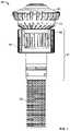
- FIG. 1is an elevation view of a first embodiment of a nozzle embodying features of the present invention
- FIG. 2is a cross-sectional view of the nozzle of FIG. 1 ;
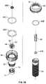
- FIGS. 3A and 3Bare top exploded perspective views of the nozzle of FIG. 1 ;
- FIGS. 4A and 4Bare bottom exploded perspective views of the nozzle of FIG. 1 ;
- FIG. 5is a perspective view of the inlet of the nozzle of FIG. 1 ;
- FIG. 6is a top plan view of the inlet of the nozzle of FIG. 1 ;
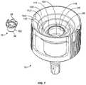
- FIG. 7is a top perspective view of the unassembled valve sleeve and nozzle housing of the nozzle of FIG. 1 ;
- FIG. 8is a top plan view of the unassembled valve sleeve and nozzle housing of the nozzle of FIG. 1 ;
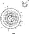
- FIG. 9is a bottom perspective view of the unassembled valve sleeve and nozzle housing of the nozzle of FIG. 1 ;
- FIG. 10is a cross-sectional view of a second embodiment of a nozzle embodying features of the present invention.
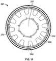
- FIG. 11is a top plan view of the inlet of the nozzle of FIG. 10 ;
- FIG. 12is a top perspective view of the assembled valve sleeve and nozzle housing of the nozzle of FIG. 10 ;
- FIG. 13is a top perspective view of the unassembled valve sleeve and nozzle housing of the nozzle of FIG. 10 ;
- FIG. 14is a bottom perspective view of the unassembled valve sleeve and nozzle housing of the nozzle of FIG. 10 ;
- FIG. 15is a cross-sectional view of a third embodiment of a nozzle embodying features of the present invention.
- FIG. 16is a top plan view of the inlet of the nozzle of FIG. 15 ;
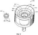
- FIG. 17is a top perspective view of the unassembled valve sleeve and nozzle housing of the nozzle of FIG. 15 ;
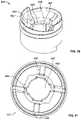
- FIG. 18is a bottom perspective view of the unassembled valve sleeve and nozzle housing of the nozzle of FIG. 15 ;
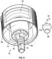
- FIG. 19is a cross-sectional view of a fourth embodiment of a nozzle embodying features of the present invention.
- FIG. 20is a perspective view of the inlet of the nozzle of FIG. 19 ;
- FIG. 21is a top plan view of the inlet of the nozzle of FIG. 19 ;
- FIG. 22is a top perspective view of the unassembled valve sleeve and nozzle housing of the nozzle of FIG. 19 ;
- FIG. 23is a bottom perspective view of the unassembled valve sleeve and nozzle housing of the nozzle of FIG. 19 ;
- FIG. 24is a cross-sectional view of a fifth embodiment of a nozzle embodying features of the present invention.
- FIG. 25is a side elevational view of the unassembled valve sleeve and nozzle housing of the nozzle of FIG. 24 ;
- FIG. 26is a top perspective view of the unassembled valve sleeve and nozzle housing of the nozzle of FIG. 24 ;
- FIG. 27is a bottom perspective view of the unassembled valve sleeve and nozzle housing of the nozzle of FIG. 24 ;
- FIG. 28is a perspective view of a prior art deflector
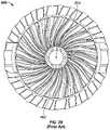
- FIG. 29is a bottom view of the prior art deflector of FIG. 28 ;
- FIG. 30is a schematic representation of the flute geometry of the prior art deflector of FIG. 28 ;
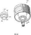
- FIG. 31is a perspective view of a first embodiment of a deflector embodying features of the present invention.
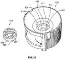
- FIG. 32is a bottom view of the deflector of FIG. 31 ;
- FIG. 33is a partial schematic representation of the flute geometry of the deflector of FIG. 31 ;
- FIG. 34is a perspective view of a second embodiment of a deflector embodying features of the present invention.
- FIG. 35is a bottom view of the deflector of FIG. 34 ;
- FIG. 36is a perspective view of a third embodiment of a deflector embodying features of the present invention.
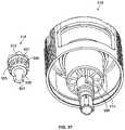
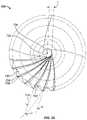
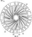
- FIG. 37is a bottom view of the deflector of FIG. 36 .
- FIGS. 1-9show a first embodiment of a sprinkler head or nozzle 10 that produces 360 degrees of coverage, or full circle irrigation, about the nozzle 10 .
- full circle nozzlesthat are intended for different maximum throw radiuses (preferably about 14 feet (4.27 meters), 18 feet (5.49 meters), and 24 feet (7.32 meters)).
- This disclosuredescribes five separate distinct models of nozzle that produce full circle irrigation patterns.
- the nozzle 10also preferably includes a radius adjustment feature, which is shown in FIGS. 1-4B , to reduce the throw radius for each nozzle (preferably to about 8 feet (2.44 meters), 13 feet (3.96 meters), and 17 feet (5.18 meters), respectively).
- the radius adjustment featureis accessible by rotating an outer wall portion of the nozzle 10 , as described further below.
- these maximum throw radiuses of these embodimentsare just illustrative to show some of the differences between embodiments and are not intended as requirements. Other embodiments may produce different maximum throw radiuses pursuant to this disclosure.
- the nozzle 10includes a rotating deflector 12 and two bodies (a valve sleeve 16 and nozzle housing 18 ) that together define an annular exit orifice 15 (or annular discharge gap) therebetween to produce full circle irrigation.
- the deflector 12is supported for rotation by a shaft 20 , which itself does not rotate. Indeed, in certain preferred forms, the shaft 20 may be fixed against rotation, such as through use of splined engagement surface 72 .
- the nozzle 10generally comprises a compact unit, preferably made primarily of lightweight molded plastic, which is adapted for convenient thread-on mounting onto the upper end of a stationary or pop-up riser (not shown).
- water under pressureis delivered through the riser to a nozzle body 17 .
- the nozzle body 17generally refers to the sub-assembly of components disposed between the filter 50 and the deflector 12 .
- the waterpreferably passes through an inlet 21 controlled by a radius adjustment feature that regulates the amount of fluid flow through the nozzle body 17 . Water is then directed generally upwardly through flow passages in the nozzle housing 18 and through the annular exit orifice 15 to produce upwardly directed water jets that impinge the underside surface of the deflector 12 for rotatably driving the deflector 12 .
- the rotatable deflector 12has an underside surface that is preferably contoured to deliver a plurality of fluid streams generally radially outwardly.
- the underside surface of the deflector 12preferably includes an array of spiral vanes 22 .
- the spiral vanes 22subdivide the water into the plurality of relatively small water streams which are distributed radially outwardly to surrounding terrain as the deflector 12 rotates.
- the vanes 22define a plurality of intervening flow channels extending upwardly and spiraling along the underside surface to extend generally radially outwardly with predetermined inclination angles.
- the upwardly directed waterimpinges upon the lower or upstream segments of these vanes 22 , which subdivide the water flow into the plurality of relatively small flow streams for passage through the flow channels and radially outward projection from the nozzle 10 .
- the offset of the flow channelsalso enables the water to drive rotation of the deflector 12 .
- this disclosurealso includes a specialized form of deflector that has been found to generally increase the maximum throw radius, and these specialized deflectors are described at the end of this disclosure.
- the deflector 12has a bore 24 for insertion of a shaft 20 therethrough.
- the bore 24is defined at its lower end by circumferentially-arranged, downwardly-protruding teeth 26 .
- these teeth 26are sized to engage corresponding teeth 28 on the valve sleeve 16 . This engagement allows a user to depress the deflector 12 , so that the deflector teeth 26 and valve sleeve teeth 28 engage, and then rotate the entire nozzle 10 to conveniently install the nozzle 10 on a retracted riser stem, as addressed further below.
- the deflector 12also preferably includes a speed control brake to control the rotational speed of the deflector 12 .
- the speed control brakeincludes a friction disk 30 , a brake pad 32 , and a seal retainer 34 .
- the friction disk 30preferably has an internal surface (or socket) for engagement with a top surface (or head) on the shaft 20 so as to fix the friction disk 30 against rotation.
- the seal retainer 34is preferably welded to, and rotatable with, the deflector 12 and, during operation of the nozzle 10 , is urged against the brake pad 32 , which, in turn, is retained against the friction disk 30 .
- Speed brakeslike the type shown in U.S. Pat. No. 9,079,202 and U.S. patent application Ser. No. 15/359,286, which are assigned to the assignee of the present application and are incorporated herein by reference in their entirety, are preferably used. Although the speed control brake is shown and preferably used in connection with nozzle 10 described and claimed herein, other brakes or speed reducing mechanisms are available and may be used to control the rotational speed of the deflector 12 .
- the deflector 12is supported for rotation by shaft 20 .
- Shaft 20extends along a central axis of the nozzle 10 , and the deflector 12 is rotatably mounted on an upper end of the shaft 20 .
- the shaft 20extends through the bore 24 in the deflector 12 and through aligned bores in the friction disk 30 , brake pad 32 , and seal retainer 34 , respectively.
- a cap 38 and o-ring, 82 Aare mounted to the top of the deflector 12 .
- the cap 38in conjunction with the o-ring, 82 A, prevent grit and other debris from coming into contact with the components in the interior of the deflector sub-assembly, such as the speed control brake components, and thereby hindering the operation of the nozzle 10 .
- the deflector 12in conjunction with the seal retainer 34 , brake pad 32 and friction disk 30 , can be extended or pulled in an upward direction while the nozzle 10 is energized and distributing fluid.
- This upward movementdisplaces the valve sleeve 16 from the nozzle housing 18 in a vertical direction to temporarily increase the size of the annular discharge gap 15 , and thus, allow for the clearance of trapped debris within the nozzle's internal passageways.
- This “pull to flush” featureallows for the flushing of trapped debris out in the direction of the fluid flow.
- a spring 40 mounted to the shaft 20energizes and tightens the engagement of the valve sleeve 16 and the nozzle housing 18 . More specifically, the spring 40 operates on the shaft 20 to bias the first of the two nozzle body portions (valve sleeve 16 ) downwardly against the second portion (nozzle housing 18 ). Mounting the spring 40 at one end of the shaft 20 results in a lower cost of assembly. As can be seen in FIG. 2 , the spring 40 is mounted near the lower end of the shaft 20 and downwardly biases the shaft 20 . In turn, the shaft shoulder 44 exerts a downward force on the washer/retaining ring 42 A and valve sleeve 16 for pressed fit engagement with the nozzle housing 18 .
- the valve sleeve 16 and nozzle housing 18are addressed in greater detail below.
- the nozzle 10also preferably include a radius control valve 46 .
- the radius control valve 46can be used to adjust the fluid flowing through the nozzle 10 for purposes of regulating the range of throw of the projected water streams. It is adapted for variable setting through use of a rotatable segment 48 located on an outer wall portion of the nozzle 10 . It functions as a valve that can be opened or closed to allow the flow of water through the nozzle 10 .
- a filter 50is preferably located upstream of the radius control valve 46 , so that it obstructs passage of sizable particulate and other debris that could otherwise damage the nozzle components or compromise desired efficacy of the nozzle 10 .
- a relatively large filter screen(relative to some filters used with other nozzles) may be used, such as, for example, a 0.02′′ ⁇ 0.02′′ (0.5 mm ⁇ 0.5 mm) filter screen. Although shown with the larger inlet filter screen, a variety of sized filters can be used with this design to prevent undesirable sized debris from entering the nozzle 10 .
- the radius control valve structurepreferably includes a nozzle collar 52 and a flow control member 54 .
- the nozzle collar 52is rotatable about the central axis of the nozzle 10 . It has an internal engagement surface 56 and engages the flow control member 54 so that rotation of the nozzle collar 52 results in rotation of the flow control member 54 .
- the flow control member 54also engages the nozzle housing 18 such that rotation of the flow control member 54 causes the member 54 to also move in an axial direction, as described further below. In this manner, rotation of the nozzle collar 52 can be used to move the flow control member 54 helically in an axial direction closer to and further away from the inlet 21 .
- the nozzle collar 52is preferably cylindrical in shape and includes an engagement surface 56 , preferably a splined surface, on the interior of the cylinder.
- the nozzle collar 52preferably also includes an outer wall 58 having an external grooved surface for gripping and rotation by a user. Water flowing through the inlet 21 passes through the interior of the cylinder and through the remainder of the nozzle body 17 to the deflector 12 . Rotation of the outer wall 58 causes rotation of the entire nozzle collar 52 .
- the nozzle collar 52is coupled to the flow control member 54 (or throttle body).
- the flow control member 54is preferably in the form of a ring-shaped nut with a central hub defining a central bore 60 .
- the flow control member 54has an external surface with two thin tabs 62 extending radially outward for engagement with the corresponding internal splined surface 56 of the nozzle collar 52 .
- the tabs 62 and internal splined surface 56interlock such that rotation of the nozzle collar 52 causes rotation of the flow control member 54 about the central axis.
- these tabs 62 of the flow control member 54act as a clutching mechanism that prevents over-travel and excessive application of torque, as well as providing a tactile and audible feedback to the user when the flow control member 54 reaches its respective limits of travel.
- the flow control member 54is coupled to the nozzle housing 18 . More specifically, the flow control member 54 is internally threaded for engagement with an externally threaded hollow post 64 at the lower end of the nozzle housing 18 . Rotation of the flow control member 54 causes it to move along the threading in an axial direction. In one preferred form, rotation of the flow control member 54 in a counterclockwise direction advances the member 54 towards the inlet 21 and away from the deflector 12 . Conversely, rotation of the flow control member 54 in a clockwise direction causes the member 54 to move away from the inlet 21 .
- the nozzle housing 18preferably includes an inner cylindrical wall 66 joined by spoke-like ribs 68 to a central hub 70 .
- the central hub 70preferably defines the bore 67 to accommodate insertion of the shaft 20 therein.
- the inside of the central hub 70is preferably splined to engage a splined surface 72 of the shaft 20 and fix the shaft 20 against rotation.
- the lower endforms the external threaded hollow post 64 for insertion in the bore 60 of the flow control member 54 , as discussed above.
- the spokes 68define flow passages 74 to allow fluid flow upwardly through the remainder of the nozzle 10 .
- a usermay rotate the outer wall 58 of the nozzle collar 52 in a clockwise or counterclockwise direction.
- the nozzle housing 18preferably includes one or more cut-out portions 76 to define one or more access windows to allow rotation of the nozzle collar outer wall 58 .
- the nozzle collar 52 , flow control member 54 , and nozzle housing 18are oriented and spaced to allow the flow control member 54 to essentially limit fluid flow through the nozzle 10 or to allow a desired amount of fluid flow through the nozzle 10 .
- the flow control member 54preferably has a radiused helical bottom surface 78 for engagement with a matching notched helical surface 79 on the inlet member.
- This matching helical surface 79acts as a valve seat but with a segmented 360 degree pattern to allow a minimum flow when the matching helical surfaces 78 and 79 are fully engaged.
- the inlet 21can be a separate insert component that snap fits and locks into the bottom of the nozzle collar 52 .
- the inlet 21also includes a bore 87 to receive the hollow post 64 of the nozzle housing 18 .
- the bore 87 and the post 64include complementary gripping surfaces so that the inlet 21 is locked against rotation.
- Rotation in a counterclockwise directionresults in helical movement of the flow control member 54 in an axial direction toward the inlet 21 .
- Continued rotationresults in the flow control member 54 advancing to the valve seat formed at the inlet 21 for restricting or significantly reducing fluid flow.
- the dimensions of the radial tabs 62 of the flow control member 54 and the splined internal surface 56 of the nozzle collar 52are preferably selected to provide over-rotation protection. More specifically, the radial tabs 62 are sufficiently flexible such that they slip out of the splined recesses upon over-rotation, i.e., clutching.
- Rotation in a clockwise directioncauses the flow control member 54 to move axially away from the inlet 21 .
- Continued rotationallows an increasing amount of fluid flow through the inlet 21 , and the nozzle collar 52 may be rotated to the desired amount of fluid flow.
- the direction of rotation of the outer wall 58 for axial movement of the flow control member 54can be easily reversed, i.e., from clockwise to counterclockwise or vice versa.
- valveWhen the valve is open, fluid flows through the nozzle 10 along the following flow path: through the inlet 21 , between the nozzle collar 52 and the flow control member 54 , through the passages 74 of the nozzle housing 18 , through the constriction formed at the valve sleeve 16 , to the underside surface of the deflector 12 , and radially outwardly from the deflector 12 .
- the nozzle 10also preferably includes a nozzle base 80 of generally cylindrical shape with internal threading 83 for quick and easy thread-on mounting onto a threaded upper end of a riser with complementary threading (not shown).
- the nozzle base 80 and nozzle housing 18are preferably attached to one another by welding, snap-fit, or other fastening method such that the nozzle housing 18 is stationary relative to the base 80 when the base 80 is threadedly mounted to a riser.
- the nozzle 10also preferably include seal members, such as seal members 82 A, 82 B, 82 C, 82 D, and 82 E, at various positions, such as shown in FIGS. 2-4B , to reduce leakage.
- the nozzle 10also preferably includes retaining rings or washers, such as retaining rings/washers 42 A and 42 B, disposed, for example, at the top of valve sleeve 16 (preferably for engagement with shaft shoulder 44 ) and near the bottom end of the shaft 20 for retaining the spring 40 .
- retaining rings or washerssuch as retaining rings/washers 42 A and 42 B, disposed, for example, at the top of valve sleeve 16 (preferably for engagement with shaft shoulder 44 ) and near the bottom end of the shaft 20 for retaining the spring 40 .
- the radius adjustment valve 46 and certain other components described hereinare preferably similar to that described in U.S. Pat. Nos. 8,272,583 and 8,925,837, which are assigned to the assignee of the present application and are incorporated herein by reference in their entirety.
- the userrotates a nozzle collar 52 to cause the flow control member 54 (which may be in the form of a throttle nut) to move axially toward and away from the valve seat at the inlet 21 to adjust the throw radius.
- the flow control member 54which may be in the form of a throttle nut
- this type of radius adjustment valve 46is described herein, it is contemplated that other types of radius adjustment valves may also be used.
- the first embodimentincludes valve sleeve 16 , nozzle housing 18 , and inlet 21 .
- this first embodimentmay have a maximum throw radius of 24 feet (7.32 meters), which may be reduced to 17 feet (5.18 meters) or lower by adjustment of the radius adjustment valve 46 .
- the maximum throw radiusis controlled, in part, by the structure of the inlet 21 and the flow passages 74 in the nozzle housing 18 .
- the whole flow path above the filter 50is generally configured to have as minimal a change in flow area and flow direction (relative to other embodiments) to provide the longest throw radius.
- the embodiments described hereinprovide examples of throw radiuses, and it should be evident that this disclosure is not limited to embodiments with any particular throw radius.
- the inlet 21is separated by ribs/spokes 94 and defines a bore 87 and separate and distinct flow passages 88 therethrough (which collectively define an annular flow passageway through the inlet 21 ).
- the bore 87is sized to receive the end of the hollow post 64 of the nozzle housing 18 therein.
- the inlet 21preferably has two helical portions 91 that are offset with respect to one another to define the helical top surface 79 , and the flow control member 54 has two corresponding offset helical portions defining its bottom surface 78 .
- this helical top surface 79acts as a valve seat for the flow control member 54 that is moveable in an axial direction toward and away from the segmented helical top surface 79 .
- the flow passages 88are defined by a central hub 90 , an outer cylindrical wall 92 , and four radial spokes 94 connecting the central hub 90 and outer wall 92 . These four flow passages 88 have a relatively large cross-section and do not significantly restrict flow through the inlet 21 (in contrast to some embodiments discussed below). In other words, the flow passages 88 are generally sized so as not to significantly reduce the energy and velocity of fluid flowing through the inlet 21 , in view of the fact that nozzle 10 is intended to have the longest throw radius of the embodiments described herein. Fluid flows up through the filter 50 , through the flow passages 88 of the inlet 21 , past the flow control member 54 (forming part of the radius adjustment valve 46 ), and then into the nozzle housing 18 .
- the valve sleeve 16is received and nested within a recess 96 of the nozzle housing 18 .
- the valve sleeve 16has a flat, ring-shaped bottom surface 98 that is supported by a support surface 100 of the nozzle housing 18 .
- the valve sleeve 16also has a gently curved (radiused) outer wall 102 that guides upwardly flowing fluid into the annular exit orifice 15 .
- the outer wall 102is gently curved so as not to significantly reduce the energy and velocity of the upwardly directed fluid.
- the spring 40biases the valve sleeve 16 against the nozzle housing 18 , i.e., it tightens the engagement between the valve sleeve 16 and nozzle housing 18 .
- the spring 40establishes a frictional engagement between the valve sleeve bottom surface 98 and the support surface 100 of the nozzle housing 18 .
- the valve sleeve 16may use this frictional engagement to rotate the entire nozzle body 17 for convenient installation of the nozzle 10 onto a riser. More specifically, the valve sleeve teeth 28 and deflector teeth 26 may engage such that a user can install the nozzle 10 by pushing down on the deflector 12 to engage the valve sleeve 16 .
- the usercan then rotate the deflector 12 to rotate the valve sleeve 16 and the rest of nozzle body 17 , including the nozzle base 80 ( FIG. 2 ).
- This rotationallows the user to thread the nozzle 10 directly onto a retracted riser of an associated spray head.
- This featureis advantageous with users of a pop-up sprinkler because it eliminates the need to use a tool to lift the riser and install the nozzle 10 .
- the nozzle housing 18preferably includes an outer cylindrical wall 104 , an intermediate cylindrical wall 106 , and the inner cylindrical wall 66 .
- these walls 104 , 106 , and 66are intended to prevent grit and other debris from entering into sensitive areas of the nozzle 10 , which may affect or even prevent operation of the nozzle 10 .
- a first debris trap 110is defined, in part, by the outer wall 104 that is inclined at an angle such that the outermost portion is at a higher elevation than the innermost portion. During normal operation, when grit, dirt, or other debris comes into contact with this outer wall 104 , it may be guided into a first channel (or first annular depression) 112 .
- first debris trap 110is defined, in part, by the outer wall 104 , first channel 112 , and intermediate wall 106 such that debris is trapped in the first channel 112 .
- a second debris trap 114includes a second channel 116 (or second annular depression) disposed between the intermediate wall 106 and the inner wall 66 .
- the debris traps 110 and 114may include two separate annular channels 112 and 116 , respectively, for capturing debris.
- the nozzle housing 18defines multiple flow passages 74 through its body, and in one preferred form, it defines five flow passages 74 .
- the nozzle housing 18preferably includes five spokes 68 that define, in part, these flow passages 74 .
- the upstream portion of the flow passages 74are located at a distal radial location relative to the shaft 20 , and the flow passages 74 then curve radially inwardly.
- the flow passages 74terminate when fluid reaches the valve sleeve 16 .
- the outer wall 102 of the valve sleeve 16 and the inner wall 66 of the nozzle housing 18define between them the annular exit orifice 15 , which constricts due to the valve sleeve 16 as fluid proceeds through this gap 15 .
- fluidinitially flows into the flow passages 74 of the nozzle housing 18 and then flows through the annular exit orifice 15 (discharge gap) defined by the nozzle housing 18 and valve sleeve 16 . It then exits the annular exit orifice 15 , impacts the underside of the deflector 12 , and is distributed radially outwardly from the deflector 12 in a full circle irrigation pattern.
- the width of the annular exit orifice 15 at the downstream endmay be about 0.024 inches (0.061 mm), or between about 0.021 and 0.025 inches (0.053 mm and 0.064 mm). As should be evident, this is just one example, and the width may be of many different sizes, depending on the size and scaling of the nozzle 10 .
- a second embodiment(nozzle 200 ) is shown in FIGS. 10-14 .
- this second embodimentmay have a maximum throw radius of 18 feet (5.49 meters), which may be reduced to 13 feet (3.96 meters) or less by adjustment of the radius adjustment valve 46 .
- the maximum throw radiusis controlled primarily by structure upstream of the annular exit orifice 215 (“upstream throttling”). More specifically, as addressed below, this maximum throw radius is controlled, in part, by the structure of the inlet 221 and the flow passages 274 in the nozzle housing 218 .
- the inlet 221is similar in shape and structure to inlet 21 of the first embodiment.
- Inlet 221is generally cylindrical in shape and defines a bore 287 sized to receive the end of the hollow post 264 of the nozzle housing 218 therein.
- the inlet 221again preferably has a helical top surface 279 (like helical top surface 79 shown in FIG. 5 ) that acts as a valve seat for the flow control member 54 .
- the profile (or thickness) and cross-sectional flow opening of the flow control member 54 itselfmay be adjusted in size in order to select a desired maximum throw radius.
- the flow passages 288 in the inlet 221are different than those of the previous embodiment. More specifically, the flow passages 288 are arranged annularly about the central hub 290 of the inlet 221 , and in one preferred form, there are twelve such circumferentially spaced flow passages 288 .
- the annularly arranged flow passages 288collectively define an annular flow path through the inlet 221 .
- the cross-section of each flow opening 288is preferably in the general shape of a trapezoid having rounded corners.
- the size, number and shape of these flow passages 288can be varied to provide the desired flow restriction necessary for the flow rate and radius requirements of the nozzle 200 .
- the inlets described hereinmay be referred to generally as flow restrictable inlets.
- these flow passages 288each preferably have a relatively narrow cross-section and function as a flow restriction through the flow restrictable inlet 221 .
- the flow passages 288are generally sized to reduce the energy and velocity of fluid flowing through the inlet 221 , in view of the fact that nozzle 200 is intended to have an intermediate throw radius relative to the embodiments described herein.
- These flow passages 288are arranged annularly in order to provide an even and balanced flow through the inlet 221 and through the rest of the nozzle 200 . In one form, they may be spaced equidistantly from one another and radially distant from the bore 287 , i.e., adjacent the outer cylindrical wall 292 . This flow restriction occurs at a point upstream of the annular exit orifice 215 . Fluid flows up through the filter 50 , through the flow passages 288 of the inlet 221 , past the radius adjustment valve 46 , and then into the nozzle housing 218 .
- valve sleeve 216is received and nested within a recess 296 of the nozzle housing 218 .
- the valve sleeve 216has a bottom surface 298 with teeth 299 therein for engaging corresponding teeth 201 in a support surface 203 of the nozzle housing 218 .
- the valve sleeve 216also has a gently curved outer wall 205 that guides upwardly flowing fluid in the annular exit orifice 215 .
- this toothed engagementmay facilitate engagement of valve sleeve 216 and nozzle housing 218 to rotate the entire nozzle body 217 for convenient installation of the nozzle 100 onto a riser.
- a usercan install the nozzle 200 by pushing down on the deflector 12 to engage the valve sleeve 216 and thereby the rest of the associated nozzle 200 . The user can then rotate the deflector 12 to rotate the valve sleeve 216 (and the nozzle 200 ) to allow the user to thread the nozzle 200 directly onto the retracted riser of an associated spray head.
- the nozzle housing 218is similar in shape in some ways to the nozzle housing 18 of the first embodiment. It preferably includes an outer cylindrical wall 207 , an intermediate cylindrical wall 209 , and an inner cylindrical wall 211 . These walls 207 , 209 , and 211 define debris traps 213 and 214 therebetween (the first debris trap 213 is between walls 207 and 209 and the second debris trap 214 is between walls 209 and 211 ).
- the nozzle housing 218also defines multiple flow passages 274 through its body, but these flow passages 274 are different than the flow passages 74 of the first embodiment. There are more flow passages 274 , and in one preferred form, the nozzle housing 218 includes ten flow passages 274 , which are defined by ten spokes 268 . As can be seen in FIG. 10 , the upstream portion of the flow passages 274 have a generally wide opening or entrance, and the flow passages 274 taper upstream from the annular exit orifice 215 . This tapering acts as a second flow restriction (in addition to the first flow restriction at the inlet 221 ) upstream of the gap 215 .
- the taperingpreferably provides a progressive and controlled reduction in cross-sectional area so as to provide the desired pressure and velocity at the annular exit orifice 215 downstream.
- the flow passages 274terminate when fluid reaches the valve sleeve 216 , and at this point, the outer wall 205 of the valve sleeve 216 and the inner wall 211 of the nozzle housing 218 define between them the annular exit orifice 215 (or discharge gap). Fluid exiting the annular exit orifice 215 strikes the underside of the deflector 12 and is distributed radially outwardly from the deflector 12 in a full circle irrigation pattern.
- a third embodiment(nozzle 300 ) is shown in FIGS. 15-18 .
- this third embodimentmay have a maximum throw radius of 14 feet (4.27 meters), which may be reduced to 8 feet (2.44 meters) by adjustment of the radius adjustment valve 46 .
- the maximum throw radiusis controlled primarily by structure upstream of the annular exit orifice 315 (“upstream throttling”). More specifically, as addressed below, this maximum throw radius is controlled, in part, by the structure of the inlet 321 and the flow passages 374 in the nozzle housing 318 .
- the inlet 321is similar in structure to the first embodiment (inlet 21 ) and the second embodiment (inlet 221 ).
- Inlet 321is generally cylindrical in shape and defines a bore 387 that receives the end of the hollow post 364 of the nozzle housing 318 . It again preferably has a helical top surface 379 (like helical top surface 79 shown in FIG. 5 and described above) that acts as a valve seat for the flow control member 54 .
- the profile (or thickness) and cross-sectional flow opening of the flow control member 54 itselfmay be adjusted in size in order to select a desired maximum throw radius.
- each flow opening 388 in the inlet 321is different.
- the flow passages 388are spaced circumferentially about the central hub 390 of the inlet 321 , and in one preferred form, there are twelve such circumferentially spaced flow passages 388 . They are preferably spaced equidistantly from one another and radially distant from the bore 387 so as to provide an even and balanced flow through the inlet 321 and through the rest of the nozzle 300 .
- the cross-section of each flow opening 388generally has an obround (or race track) shape or may have a circular or oval shape, depending on what is required, for example, based on injection mold tooling parameters.
- these flow passages 388each have a relatively narrow cross-section and act as a flow restriction through the inlet 321 . Further, these flow passages 388 have a smaller combined cross-sectional area than the combined cross-sectional area of the flow passages 288 of the second embodiment (nozzle 200 ). As should be evident, the number and cross-sectional area of the flow passages 388 may be selected to adjust to a desired maximum throw radius.
- the flow passages 388are generally sized to reduce the energy and velocity of fluid flowing through the inlet 321 , in view of the fact that nozzle 300 is intended to have the shortest maximum throw radius relative to the embodiments described herein. Like the second embodiment (nozzle 200 ), this flow restriction occurs at a point upstream of the annular exit orifice 315 . Fluid flows up through the filter 50 , through the flow passages 388 of the inlet 321 , past the radius adjustment valve 46 , and then into the nozzle housing 318 .
- valve sleeve 316is received and nested within a recess 396 of the nozzle housing 318 .
- the valve sleeve 316preferably has a bottom surface 398 with teeth 399 therein for engaging corresponding teeth 301 in a support surface 303 of the nozzle housing 318 .
- the valve sleeve 316again has a gently curved outer wall 305 that guides upwardly flowing fluid in the annular exit orifice 315 .
- a usercan install the nozzle 300 by pushing down the deflector 12 to engage the deflector teeth 26 with the teeth 399 of the valve sleeve 316 and rotating to allow the user to thread the nozzle 300 directly onto the riser of an associated spray head.
- the nozzle housing 318includes some of the structure and features of the nozzle housings 18 and 218 of the first and second embodiments, respectively. It preferably includes debris traps 313 and 314 . More specifically, it includes an outer cylindrical wall 307 , an intermediate cylindrical wall 309 , and an inner cylindrical wall 311 (with the first debris trap 313 being defined by walls 307 and 309 and the second debris trap 314 being defined by walls 309 and 311 ).
- the flow passages 374 of the nozzle housing 318are different than the flow passages 74 of the first embodiment (nozzle 10 ).
- the nozzle housing 318includes ten flow passages 374 defined by ten spokes 368 .
- the upstream portion of the flow passages 374have a generally wide opening or entrance, and the flow passages 374 taper upstream from the annular exit orifice 315 . This tapering acts as a second flow restriction (in addition to the first flow restriction at the inlet 321 ) upstream of the gap 315 .
- the rate of tapering (constriction) and the start of the taperingmay be adjusted or fine-tuned (preferably near the start of the flow passages 374 ) in order to achieve a desired flow rate and velocity at the annular exit orifice 315 downstream.
- the constrictionpreferably starts at an earlier upstream point than the flow passages 274 of the second embodiment to achieve a lower desired exit velocity and produce a shorter maximum throw radius.
- the flow passages 374end at the valve sleeve 316 .
- the outer wall 305 of the valve sleeve 316 and the inner wall 311 of the nozzle housing 318define between them the annular exit orifice 315 .
- a fourth embodiment (nozzle 400 )is shown in FIGS. 19-23 .
- this fourth embodimentmay have a nominal design throw radius of 18 feet (5.49 meters), which may be reduced to 13 feet (3.96 meters) by adjustment of the radius adjustment valve 46 .
- the general range of throw radiusis therefore like that of the second embodiment (nozzle 200 ).
- the nominal design throw radiusis controlled primarily by the nozzle structure at or just before the annular exit orifice 415 (“downstream throttling”). More specifically, as addressed below, this maximum throw radius is controlled, in part, by the combination of the structure of the valve sleeve 416 and nozzle housing 418 at or just before the annular exit orifice 415 .
- an inlet 421 similar to the inlet 21 from the first embodiment (nozzle 10 ) having a bore 487 and four flow passages 488is preferably used.
- the four arcuate flow passages 488are defined by a central hub 490 , an outer cylindrical wall 492 , and four radial spokes 494 connecting the central hub 490 and outer wall 492 .
- the general discussion above regarding inlet 21is incorporated herein, but the four flow passages 488 preferably define a smaller cross-sectional area than those of inlet 21 .
- the radial spokes 494are preferably thicker and extend further in an axial direction to provide greater flow restriction than inlet 21 , in view of the desired reduced maximum throw radius relative to the first embodiment. Fluid flows up through the filter 50 , through the flow passages 488 of the inlet 421 , past the radius adjustment valve 46 , and then into the nozzle housing 418 .
- the valve sleeve 416is nested within a recess 496 of the nozzle housing 418 .
- the valve sleeve 416preferably has a flat, ring-shaped bottom surface 498 that engages a corresponding ring-shaped support surface 403 of the nozzle housing 418 .
- this frictional engagementpreferably permits a user to push down and rotate the valve sleeve 416 to rotate the entire nozzle 400 and thread it onto a retracted riser during installation.
- the valve sleeve 416preferably has a first cylindrical outer wall 405 disposed upstream (beneath) a second cylindrical outer wall 407 with the second outer wall 407 having a larger radius than the first outer wall 405 . It also includes a second ring-shaped horizontal surface 409 connecting the first outer wall 405 and second outer wall 407 . As addressed further below, this structure creates a dogleg (or zigzag) in the flow path at and just before the annular exit orifice 415 , resulting in loss of energy and velocity at this exit orifice 415 .
- the nozzle housing 418includes structure that defines the flow path through its structure, including a first cylindrical wall 411 , a second cylindrical wall 413 , a third cylindrical wall 417 , an annular ledge 419 connecting the second and third cylindrical walls 413 and 417 , and flow passages 474 .
- the nozzle housing 418includes ten flow passages 474 defined by ten spokes 468 connecting the first and second cylindrical walls 411 and 413 .
- the flow passages 474have a generally wide opening or entrance and then taper to and terminate in a narrower cross-section.
- Fluidflows into and through the flow passages 474 and then upwardly in an annular flow path until impacting the horizontal surface 409 of the valve sleeve 418 , which flares radially outwardly into the flow path. This impact disrupts fluid flow, resulting in a loss of energy and velocity.
- the flow path at this pointis defined by the combination of the valve sleeve 416 (second outer wall 407 and horizontal surface 409 ) and the nozzle housing 418 (third cylindrical wall 417 ). Fluid then flows through the annular exit orifice 415 (between second outer wall 407 and third cylindrical wall 417 ), impacts the underside of the deflector 12 , and is distributed radially outwardly from the deflector 12 in a full circle irrigation pattern.
- a fifth embodiment(nozzle 500 ) is shown in FIGS. 24-27 .
- this fifth embodimentmay have a nominal design throw radius of 14 feet (4.27 meters), which may be reduced to 8 feet (2.44 meters) by adjustment of the radius adjustment valve 46 .
- the general range of throw radiusis therefore like that of the third embodiment (nozzle 300 ).
- the maximum throw radiusis controlled primarily by the nozzle structure at or just before the annular exit orifice 515 (“downstream throttling”). More specifically, as addressed below, this maximum throw radius is controlled, in part, by the combination of the structure of the valve sleeve 516 and nozzle housing 518 at or just before the annular exit orifice 515 .
- the inlet 421 from the fourth embodimentis preferably used ( FIGS. 20 and 21 ), and the above description of inlet 421 is incorporated herein.
- the inlet 421has four flow passages 488 permitting flow through the inlet 421 . Fluid flows up through the filter 50 , through the flow passages 488 of the inlet 421 , past the radius adjustment valve 46 , and then into the nozzle housing 518 .
- valve sleeve 516is nested within a recess 596 of the nozzle housing 518 .
- the valve sleeve 516 of the fifth embodimenthas certain structure similar to the valve sleeve 416 of the fourth embodiment (nozzle 400 ), including a first cylindrical outer wall 505 disposed upstream (beneath) a second cylindrical outer wall 507 with the second outer wall 507 having a larger radius than the first outer wall 505 .
- valve sleeve 516also includes different structure.
- the valve sleeve 516preferably has a key portion 501 (or protrusion) projecting from a bottom surface 598 that is received within a corresponding notch 503 (or recess) of the nozzle housing 518 (which helps maintain the clocked alignment of the valve sleeve 516 relative to the nozzle housing 518 , as addressed below).
- itpreferably includes a number of circumferentially spaced segments (or ribs) 509 disposed on the first outer wall 505 . As addressed further below, this structure creates a zig-zag (or break) in the flow path at and just before the annular exit orifice 515 , resulting in loss of energy and velocity at this exit orifice 515 .
- the nozzle housing 518also includes some structure similar to the fourth embodiment (nozzle 400 ) but also includes different features (such as notch 503 and a scalloped wall 517 ).
- the nozzle housing 518includes structure that defines the flow path through its interior, including a first cylindrical wall 511 , a second cylindrical wall 513 , a scalloped wall 517 , an annular ledge 519 connecting the walls 513 and 517 , and flow passages 574 .
- the nozzle housing 518includes ten flow passages 574 defined by ten spokes 568 connecting the first and second cylindrical walls 511 and 513 . As can be seen in FIG.
- the flow passages 574have a generally wide opening or entrance and then taper to and terminate in a narrower cross-section. Fluid flows into and through the flow passages 574 and then upwardly in an annular flow path until impacting the valve sleeve 516 , which flares radially outward into the flow path. This impact disrupts fluid flow, resulting in a loss of energy and velocity.
- the flow path at this pointis defined by the combination of the valve sleeve 516 (second outer wall 507 and ribs 509 ) and the nozzle housing 518 (scalloped wall 517 ).
- Fluidflows through the flow channels 523 defined by the ribs 509 , then flows through the annular exit orifice 515 (between second outer wall 507 and scalloped wall 517 ), impacts the underside of the deflector 12 , and is distributed radially outwardly from the deflector 12 in a full circle irrigation pattern.
- the segments/ribs 509produce segmented fluid streams. Fluid initially proceeds vertically through the interior of the nozzle housing 518 , is then directed radially outwardly, and then again proceeds generally vertically through the annular exit orifice 515 . Without the scalloped wall 517 , it has been found that the resulting streams directed toward the deflector 12 produce a spoky and uneven appearing irrigation pattern. When the scalloping in the scalloped wall 517 is angularly aligned or clocked in alignment with the segments/ribs 509 , the resulting streams produce a more even irrigation pattern.
- the valve sleeveincludes 13 ribs 509 defining 13 flow channels 523
- the nozzle housing 518includes 13 individual scallops 521 , i.e., the convex rounded projections extending radially into wall 515 .
- each scallop 521is angularly aligned with a rib 509 .
- the centerline of each rib 509is preferably aligned with a centerline of one of the scallops 521 .
- the key portion 501helps maintain the proper angular or clocked alignment assuring the proper alignment of both features in the nozzle housing 518 and valve sleeve 516 .
- any deflector suitable for distributing fluid radially outwardmay be used with the nozzles described herein.
- the nozzlesmay also use a specialized form of deflector that has been found to generally increase the maximum throw radius.
- these specialized deflectorsinclude curved flutes or vanes (or grooves or channels) on their underside that are “laterally offset.” This lateral offset means generally that, if extended, the flutes or vanes do not extend to the axis of the deflector. Instead, they generally terminate at a certain radial distance “offset” from the center.
- this lateral offsetallows the use of “straighter” flutes/vanes than previously used, i.e., the flutes/vanes have a larger radius of curvature.
- the fluid impacting the deflectordrives the deflector more efficiently, i.e., the fluid loses less energy and may be distributed a further distance from the deflector.
- By adjusting the lateral offset and curvature of the flutes/vanesone can tune both the drive torque and the distance of throw for specific nozzles. In effect, the same or greater radius can be achieved for a given nozzle utilizing lower and more laminar flow from the annular exit orifice of the nozzle using laterally offset deflectors with straightened flutes.
- deflectorsmay be used with nozzles described herein for full circle irrigation, it is also contemplated that may be used with other types of nozzles, such as, without limitation, variable arc nozzles, strip nozzles, and any type of rotary nozzle using a rotating deflector.
- FIGS. 28-30show one form of a prior art deflector 600 .
- each flute 602generally includes a first sidewall 630 and a second sidewall 632 defining a channel 634 therebetween.
- FIG. 30shows a simplified representation of the basic flute geometry of the deflector 600 in which the flutes 602 have been extended inwardly.
- the flutes 602each define the same general shape, and if extended inwardly, they will each intersect with and terminate at or about the central axis 604 of the deflector 600 . In other words, these flutes 602 are not laterally offset from the central axis 604 of the deflector 600 .
- FIGS. 31-33show a specialized form of deflector 700 with flutes 702 disposed on the underside surface 703 resulting in a greater throw distance than deflector 600 .
- the flutes 702if extended inwardly, will not each intersect with and terminate at or about the central axis 704 of the deflector 700 .
- the inlet end 705is arcuately extended inwardly, it does not intersect at or near the central axis 704 .
- These flutes 702are laterally offset from the central axis 704 of the deflector 700 .
- FIG. 33shows a partial representation of the basic flute geometry of the deflector 700 in which the flutes 702 have been extended inwardly.
- Each flute 702generally includes a first sidewall 730 and a second sidewall 732 defining a channel 734 between them (the structure of the sidewalls 730 and 732 has been simplified and made more uniform in the representation).
- the flutes 702include an inner arcuate portion 706 with a predetermined radius of curvature (r) and an outer linear portion 708 extending to an outlet end 709 .
- the flutes 702are laterally offset such that the inner arcuate portion 706 terminates at a lateral offset distance (l) from the central axis 704 .
- the innermost points of the flutes 702collectively define a circle 712 with a predetermined radius corresponding to the lateral offset distance ( 1 ). Further, if the outer linear portion 708 is extended outwardly and a parallel radial line 710 is drawn outwardly from the central axis 704 , an exit offset distance (e) can be determined. As a result of this lateral offset, the flutes 702 may have a greater radius of curvature (less curved) in order to achieve a comparable vane exit offset distance (e), which is desired to drive rotation of the deflector 700 .
- the exit offset distance (e)represents a combination of the lateral offset and the flute curvature, so by providing a lateral offset, the flute curvature can be reduced to achieve an exit offset distance (e) that is comparable to the deflector 600 having no lateral offset plus a flute with greater curvature.
- the lateral offset (l)may be in the range of about 0.05 inches (1.27 mm) and the radius of curvature (r) may be in the range of about 0.80 inches (20.32 mm) resulting in the exit offset distance (e) of about 0.10 inches (2.54 mm).
- the amount of the exit offset (0.10 inches) (2.54 mm) due to the lateral offset from the central axis (0.05 inches) (1.27 mm)is 50% of the exit offset.
- the dimensions and proportionsmay be adjusted such that different proportions of the exit offset (e) are due to the lateral offset (l) and the radius of curvature (r), i.e., different combinations of lateral offset distances and curvature may be selected.
- the dimensions indicated hereinare non-limiting examples only and are provided for illustrative purposes.
- the exit offset distance (e)can be determined by extending the linear portion 708 outwardly and drawing a parallel radial line 710 outwardly from the central axis 704 .
- this exit offset distance (e)may be generally in the amount of about 0.10 inches (2.54 mm).
- these laterally offset flutes 702may have different values for the radius of curvature (r) and the exit offset distance (e).
- the radius of curvature (r)may be increased in order to achieve a comparable, desired exit offset distance (e).
- the flutes 702can be straighter.
- the fluid impacting the deflector 700retains more energy than the fluid impacting the deflector 600 , which results in a greater throw distance outwardly from the deflector 700 .
- the values providedare only examples, and many combinations of lateral offset distance ( 1 ), exit offset distance (e), and radius of curvature (r) may be selected.
- the flutes 702(when extended inwardly) do not originate from the central axis 704 , or centerline, of the deflector 700 but instead originate at or closer to the central hub 714 .
- the central hub 714defines a bore 716 for receiving a shaft that supports the deflector 700 . It has been found that this flute arrangement generates torque near the center of the deflector 700 and may use straighter flutes 702 that result in a greater throw distance.
- This deflector 700(and the deflectors described below) may be used with the full circle nozzles described above (and with other types of irrigation nozzles) to generally increase the nominal throw distance of those nozzles. These greater throw distances may help provide a uniform irrigation coverage when using multiple overlapping nozzles to collectively cover an irrigation area and may allow the use of fewer nozzles to cover that area.
- FIGS. 34 and 35show another form of deflector 800 with laterally offset flutes 802 .
- the flutes 802again include an inner arcuate portion 806 and an outer linear portion 808 .
- the flutes 802are laterally offset such that the inner arcuate portion 806 terminates at a lateral offset distance from the central axis 804 .
- the lateral offsetmay be in the range of about 0.08 inches (2.03 mm) and the radius of curvature may be in the range of about 1.90 inches (48.26 mm) resulting in the exit offset distance of about 0.10 inches (2.54 mm) (the same exit offset distance as for deflector 700 ).
- the amount of the exit offset (0.10 inches) (2.54 mm) due to the lateral offset from the central axis (0.08 inches) (2.03 mm)is 80% of the exit offset.
- the flutes 802 of deflector 800are laterally offset more and are straighter than the flutes 702 of deflector 700 .
- the dimensions indicated hereinare non-limiting examples only and are provided for illustrative purposes.
- the arrangement of the flutes 802 on the deflector 802is such that they are not all spaced evenly from adjacent flutes 802 .
- the deflector 800includes four sets of six flutes 802 (resulting in a total of 24 flutes 802 ), and the angular extent defined by each set of flutes 802 is 90 degrees.
- the angular extent of each of five flutes 802 of each set (and adjacent rib 816 )is about 13 degrees such that the sixth flute 802 of each set (and its adjacent rib 818 ) is about 25 degrees, i.e., the flutes 802 are not all equiangular.
- rib 818is larger than the other ribs 816 .
- the number and size of the flutes 802may be modified as desired to modify the distribution and throw characteristics of the nozzle.
- FIGS. 36 and 37show another form of deflector 900 with laterally offset flutes 902 that is a modified form of deflector 800 .
- the lateral offsetmay still be in the range of about 0.08 inches (2.03 mm) and the radius of curvature may be in the range of about 1.90 inches (48.26 mm) resulting in the exit offset distance of about 0.10 inches (2.54 mm).
- the amount of the exit offset (0.10 inches) (2.54 mm) due to the lateral offset from the central axis (0.08 inches) (2.03 mm)is 80% of the exit offset.
- the shape and curvature of flutes 902is similar to that of flutes 802 of deflector 800 .
- the deflector 900includes four sets of five large flutes 920 (resulting in a total of 20 large flutes 920 ).
- a sixth smaller flute 922has been added to each set.
- This sixth smaller flute 922has an inlet end 924 that is more radially distant than the inlet ends 926 of the large flute 920 .
- the depth of the flutesmay be configured such that there is one flute for a longer throw distance (deeper flute), four flutes for an intermediate throw distance, and a small flute for short distance.
- the above dimensions and the number and size of the flutesare intended as non-limiting examples.
Landscapes
- Nozzles (AREA)
Abstract
Description
Claims (25)
Priority Applications (2)
| Application Number | Priority Date | Filing Date | Title |
|---|---|---|---|
| US15/649,072US11511289B2 (en) | 2017-07-13 | 2017-07-13 | Rotary full circle nozzles and deflectors |
| US16/219,595US11666929B2 (en) | 2017-07-13 | 2018-12-13 | Rotary full circle nozzles and deflectors |
Applications Claiming Priority (1)
| Application Number | Priority Date | Filing Date | Title |
|---|---|---|---|
| US15/649,072US11511289B2 (en) | 2017-07-13 | 2017-07-13 | Rotary full circle nozzles and deflectors |
Related Child Applications (1)
| Application Number | Title | Priority Date | Filing Date |
|---|---|---|---|
| US16/219,595DivisionUS11666929B2 (en) | 2017-07-13 | 2018-12-13 | Rotary full circle nozzles and deflectors |
Publications (2)
| Publication Number | Publication Date |
|---|---|
| US20190015849A1 US20190015849A1 (en) | 2019-01-17 |
| US11511289B2true US11511289B2 (en) | 2022-11-29 |
Family
ID=65000568
Family Applications (2)
| Application Number | Title | Priority Date | Filing Date |
|---|---|---|---|
| US15/649,072Active2038-01-13US11511289B2 (en) | 2017-07-13 | 2017-07-13 | Rotary full circle nozzles and deflectors |
| US16/219,595Active2038-06-29US11666929B2 (en) | 2017-07-13 | 2018-12-13 | Rotary full circle nozzles and deflectors |
Family Applications After (1)
| Application Number | Title | Priority Date | Filing Date |
|---|---|---|---|
| US16/219,595Active2038-06-29US11666929B2 (en) | 2017-07-13 | 2018-12-13 | Rotary full circle nozzles and deflectors |
Country Status (1)
| Country | Link |
|---|---|
| US (2) | US11511289B2 (en) |
Cited By (2)
| Publication number | Priority date | Publication date | Assignee | Title |
|---|---|---|---|---|
| US11933417B2 (en) | 2019-09-27 | 2024-03-19 | Rain Bird Corporation | Irrigation sprinkler service valve |
| US12030072B2 (en) | 2020-11-16 | 2024-07-09 | Rain Bird Corporation | Pressure regulation device and method for irrigation sprinklers |
Families Citing this family (14)
| Publication number | Priority date | Publication date | Assignee | Title |
|---|---|---|---|---|
| US9492832B2 (en) | 2013-03-14 | 2016-11-15 | Rain Bird Corporation | Sprinkler with brake assembly |
| US9700904B2 (en) | 2014-02-07 | 2017-07-11 | Rain Bird Corporation | Sprinkler |
| CN106918263A (en)* | 2015-12-28 | 2017-07-04 | 上海艾客制冷科技有限公司 | A kind of wide cut changeable flow water distribution system |
| US10322423B2 (en) | 2016-11-22 | 2019-06-18 | Rain Bird Corporation | Rotary nozzle |
| US11154877B2 (en) | 2017-03-29 | 2021-10-26 | Rain Bird Corporation | Rotary strip nozzles |
| US11511289B2 (en) | 2017-07-13 | 2022-11-29 | Rain Bird Corporation | Rotary full circle nozzles and deflectors |
| US11358160B2 (en)* | 2018-08-10 | 2022-06-14 | Xcad Valve And Irrigation, Inc | Sprinkler braking mechanism |
| US11000866B2 (en)* | 2019-01-09 | 2021-05-11 | Rain Bird Corporation | Rotary nozzles and deflectors |
| US11059056B2 (en) | 2019-02-28 | 2021-07-13 | Rain Bird Corporation | Rotary strip nozzles and deflectors |
| US11406999B2 (en)* | 2019-05-10 | 2022-08-09 | Rain Bird Corporation | Irrigation nozzle with one or more grit vents |
| CN111871633B (en)* | 2020-07-09 | 2022-01-07 | 浙江农丰软管股份有限公司 | Can be according to agricultural sprinkling irrigation shower nozzle of temperature variation regulating pondage |
| US12186766B2 (en)* | 2020-12-01 | 2025-01-07 | Nelson Irrigation Corporation | Nozzle and sprinkler for center pivot end |
| WO2022264044A1 (en)* | 2021-06-16 | 2022-12-22 | Netafim Ltd | Sprinkler |
| CN119406599B (en)* | 2025-01-09 | 2025-04-15 | 山东华宇工学院 | An adjustable nozzle device for forestry machinery and a method of using the same |
Citations (148)
| Publication number | Priority date | Publication date | Assignee | Title |
|---|---|---|---|---|
| US581252A (en) | 1897-04-20 | William quayle | ||
| US598873A (en)* | 1898-02-08 | Nozzle | ||
| US1286333A (en) | 1917-02-28 | 1918-12-03 | Elmer Johnson | Fire-extinguisher spray-nozzle. |
| US3030032A (en) | 1960-08-15 | 1962-04-17 | Dairy Equipment Co | Liquid distribution device |
| GB908314A (en) | 1960-01-13 | 1962-10-17 | Heinrich Wilhelm Arthur Von Di | Improvements in spray nozzles for spraying cleaning fluid over surfaces such as ships' decks |
| IL35182A (en) | 1970-08-28 | 1973-04-30 | Naan Mech Works | Sprinklers |
| US4099675A (en) | 1975-07-24 | 1978-07-11 | Balcke-Durr Ag | Sprinkler head for water spray cooling installations |
| US4235379A (en) | 1978-04-24 | 1980-11-25 | Rain Bird Sprinkler Mfg. Corp. | Interchangeable nozzle apparatus for full or part circle irrigation sprinklers |
| US4261515A (en) | 1979-12-28 | 1981-04-14 | Peretz Rosenberg | Rotary sprinkler |
| US4471908A (en) | 1981-03-09 | 1984-09-18 | The Toro Company | Pattern sprinkler head |
| US4512519A (en) | 1982-10-05 | 1985-04-23 | Mifalei Matechet Naan | Sprinkler |
| US4632312A (en) | 1984-12-14 | 1986-12-30 | Rain Bird Consumer Products Mfg. Corp. | Impact drive sprinkler |
| US4681263A (en) | 1985-07-29 | 1987-07-21 | Cockman Haggie I | Low profile sprinkler head |
| US4711399A (en) | 1983-06-24 | 1987-12-08 | Peretz Rosenberg | Liquid spraying devices |
| US4728040A (en) | 1982-09-29 | 1988-03-01 | Senninger Irrigation, Inc. | Interchangeably connectable sprinkler deflector and hose |
| US4754925A (en) | 1984-10-24 | 1988-07-05 | Zvi Rubinstein | Rotating miniature sprinkler for irrigation systems |
| US4760958A (en) | 1986-02-10 | 1988-08-02 | Plastro Gvat And Agroteam Consultants Ltd. | Water sprinkler |
| US4783004A (en) | 1985-05-03 | 1988-11-08 | Imperial Underground Sprinkler Co. | Ball drive sprinkler |
| US4796811A (en) | 1988-04-12 | 1989-01-10 | Nelson Irrigation Corporation | Sprinkler having a flow rate compensating slow speed rotary distributor |
| US4815662A (en) | 1987-11-23 | 1989-03-28 | Hunter Edwin J | Stream propelled rotary stream sprinkler unit with damping means |
| US4832264A (en) | 1983-06-24 | 1989-05-23 | Peretz Rosenberg | Rotary sprinklers |
| US4842201A (en) | 1986-06-26 | 1989-06-27 | Hunter Edwin J | Rotary stream sprinkler unit |
| US4867379A (en) | 1986-06-26 | 1989-09-19 | Hunter Edwin J | Rotary stream sprinkler unit |
| US4898332A (en) | 1986-06-26 | 1990-02-06 | Edwin J. Hunter | Adjustable rotary stream sprinkler unit |
| US4932590A (en) | 1989-08-07 | 1990-06-12 | Hunter Edwin J | Rotary stream sprinkler unit with rotor damping means |
| US4944456A (en) | 1988-04-29 | 1990-07-31 | Dan Mamtirim | Rotary sprinkler |
| US4957240A (en) | 1987-10-01 | 1990-09-18 | Peretz Rosenberg | Rotary sprinklers |
| US4961534A (en) | 1987-11-20 | 1990-10-09 | The Toro Company | Sprinkler nozzle module |
| US4967961A (en) | 1986-06-26 | 1990-11-06 | Hunter Edwin J | Rotary stream sprinkler unit |
| US5031840A (en) | 1989-09-13 | 1991-07-16 | The Toro Company | Adjustable radius sprinkler nozzle |
| US5050800A (en) | 1989-03-06 | 1991-09-24 | Lamar John W | Full range sprinkler nozzle |
| US5058806A (en) | 1990-01-16 | 1991-10-22 | Nelson Irrigation Corporation | Stream propelled rotary pop-up sprinkler with adjustable sprinkling pattern |
| US5152458A (en) | 1991-06-13 | 1992-10-06 | Curtis Harold D | Automatically adjustable fluid distributor |
| US5158232A (en) | 1987-11-20 | 1992-10-27 | The Toro Company | Sprinkler nozzle module |
| US5205491A (en) | 1990-12-05 | 1993-04-27 | Lego M. Lemelshtrich Ltd. | Static sector-type water sprinkler |
| US5226602A (en) | 1989-09-13 | 1993-07-13 | The Toro Company | Adjustable radius sprinkler nozzle |
| US5288022A (en) | 1991-11-08 | 1994-02-22 | Nelson Irrigation Corporation | Part circle rotator with improved nozzle assembly |
| US5360167A (en) | 1989-09-13 | 1994-11-01 | The Toro Company | Adjustable radius sprinkler nozzle |
| US5381960A (en) | 1993-08-23 | 1995-01-17 | Senninger Irrigation, Inc. | Wobbling irrigation sprinkler head including a magnet for initial tilt |
| US5415348A (en) | 1993-08-31 | 1995-05-16 | Nelson Irrigation Corporation | Quick change and easily identifiable nozzle construction for use in modular sprinkler assembly |
| US5439174A (en) | 1994-03-15 | 1995-08-08 | Nelson Irrigation Corporation | Nutating sprinkler |
| US5456411A (en) | 1994-01-07 | 1995-10-10 | Hunter Industries, Inc. | Quick snap nozzle system |
| FR2730901A1 (en) | 1995-02-28 | 1996-08-30 | Oechsner De Coninck Hubert | ROTARY MICRO SPRINKLER FOR IRRIGATION |
| US5588595A (en) | 1994-03-15 | 1996-12-31 | Nelson Irrigation Corporation | Nutating sprinkler |
| US5669449A (en) | 1995-02-28 | 1997-09-23 | Central Sprinkler Co. | Directional sprinklers |
| US5671886A (en) | 1995-08-23 | 1997-09-30 | Nelson Irrigation Corporation | Rotary sprinkler stream interrupter with enhanced emitting stream |
| US5699962A (en) | 1994-01-07 | 1997-12-23 | Hunter Industries, Inc. | Automatic engagement nozzle |
| US5718381A (en) | 1994-08-24 | 1998-02-17 | Gardena Kress + Kastner Gmbh | Sprinkler for discharging a fluid |
| US5762269A (en) | 1996-05-14 | 1998-06-09 | Nelson Irrigation Corporation | Nozzle clip |
| DE19925279A1 (en) | 1998-06-18 | 1999-12-23 | Coutier Moulage Gen Ind | Water spray for cleaning a vehicle windscreen |
| US6059044A (en) | 1998-05-15 | 2000-05-09 | Grinnell Corporation | Fire protection sprinkler and deflector |
| US6085995A (en) | 1998-06-24 | 2000-07-11 | Kah, Jr.; Carl L. C. | Selectable nozzle rotary driven sprinkler |
| US6092739A (en) | 1998-07-14 | 2000-07-25 | Moen Incorporated | Spray head with moving nozzle |
| US6123272A (en) | 1998-10-16 | 2000-09-26 | Coltec Industrial Products Inc. | Nozzle assembly |
| US6234411B1 (en) | 2000-06-09 | 2001-05-22 | Anthony Manufacturing Corporation, Residential Products Division | Combined nozzle set and lift tool for a pop-up sprinkler |
| US6254013B1 (en) | 1999-07-13 | 2001-07-03 | Moen Incorporated | Spray head for use with low pressure fluid sources |
| US6267299B1 (en) | 2000-04-05 | 2001-07-31 | Nelson Irrigation Corporation | Nutating sprinkler with gimbal bearing |
| US6276460B1 (en) | 2000-05-23 | 2001-08-21 | Reliable Automatic Sprinkler Co., Inc. | Residental sprinkler arrangement |
| US6341733B1 (en) | 2000-02-03 | 2002-01-29 | Nelson Irrigation Corporation | Nutating sprinkler |
| US6435427B1 (en) | 2001-01-16 | 2002-08-20 | Coltec Industries, Inc. | Nozzle assembly with an extendable turret |
| US6439477B1 (en) | 2000-02-03 | 2002-08-27 | Nelson Irrigation Corporation | Nutating sprinkler |
| US20020139868A1 (en) | 2001-03-28 | 2002-10-03 | George Sesser | Adjustable arc, adjustable flow rate sprinkler |
| US6481644B1 (en) | 1998-08-26 | 2002-11-19 | Odd A. Olsen | Device by sprinkler nozzle |
| US6516893B2 (en) | 2001-06-05 | 2003-02-11 | The Reliable Automatic Sprinkler Co.,Inc. | Residential sprinkler arrangement |
| US20030075620A1 (en) | 2001-07-25 | 2003-04-24 | Kah Carl L.C. | Selected range arc settable spray nozzle with pre-set proportional connected upstream flow throttling |
| US6651904B2 (en) | 2000-02-24 | 2003-11-25 | Claber S.P.A. | Multi-jet watering nozzle with counter-rotating elements for underground pop-up sprinkler |
| US6688539B2 (en) | 2001-10-19 | 2004-02-10 | Nelson Irrigation Corporation | Water distribution plate for rotating sprinklers |
| US6736332B2 (en) | 2001-03-28 | 2004-05-18 | Nelson Irrigation Corporation | Adjustable arc, adjustable flow rate sprinkler |
| US6811098B2 (en) | 2002-12-02 | 2004-11-02 | Arno Drechsel | Sprinkler device, especially for plants the spray distribution of water and other similar liquids |
| US6814304B2 (en) | 2002-12-04 | 2004-11-09 | Rain Bird Corporation | Rotating stream sprinkler with speed control brake |
| US6883727B2 (en) | 2003-08-19 | 2005-04-26 | Rain Bird Corporation | Rotating stream sprinkler with ball drive |
| US6942164B2 (en) | 2003-02-28 | 2005-09-13 | Rain Bird Corporation | Rotating stream sprinkler with turbine speed governor |
| US6976543B1 (en) | 2000-11-22 | 2005-12-20 | Grinnell Corporation | Low pressure, extended coverage, upright fire protection sprinkler |
| US7032836B2 (en) | 2001-03-28 | 2006-04-25 | Nelson Irrigation Corporation | Adjustable arc, adjustable flow rate sprinkler |
| US7100842B2 (en) | 2004-07-07 | 2006-09-05 | Nelson Irrigation Corporation | Two-axis full-circle sprinkler |
| US7143957B2 (en) | 2004-07-07 | 2006-12-05 | Nelson Irrigation Corporation | Two-axis full-circle sprinkler with bent, rotating nozzle |
| US7156322B1 (en) | 2003-09-22 | 2007-01-02 | Heitzman Charles J | Irrigation sprinkler unit with cycling flow rate |
| US7232081B2 (en) | 2001-03-15 | 2007-06-19 | Kah Jr Carl L | Spray nozzle with adjustable ARC spray elevation angle and flow |
| US20080054093A1 (en) | 2006-08-31 | 2008-03-06 | Nelson Irrigation Corporation | Distributor plate and diffuser plate on sleeved shaft |
| US20080087743A1 (en) | 2006-10-15 | 2008-04-17 | Netafim Ltd | Rotary sprinkler |
| US7395977B2 (en) | 2004-11-22 | 2008-07-08 | Senninger Irrigation Inc. | Sprinkler apparatus |
| US20080257982A1 (en) | 2007-04-19 | 2008-10-23 | Kah Carl L C | Sprinkler head nozzle assembly with adjustable arc, flow rate and stream angle |
| US20090078788A1 (en) | 2006-05-15 | 2009-03-26 | Tony Holmes | Sprinkler Head |
| US20090108099A1 (en)* | 2007-10-30 | 2009-04-30 | Porter Lamonte D | Rotary Stream Sprinkler Nozzle with Offset Flutes |
| US7584904B2 (en) | 2006-04-24 | 2009-09-08 | Nelson Irrigation Corporation | Sprinkler with viscous hesitator |
| US7597276B2 (en) | 2006-04-09 | 2009-10-06 | Jain Irrigation Inc | Ultra low flow spray head |
| US7597273B2 (en) | 2005-07-15 | 2009-10-06 | Rain Bird Corporation | Speed control apparatus for a rotary sprinkler |
| US7611077B2 (en) | 2006-02-08 | 2009-11-03 | Hunter Industries, Inc. | Adjustable flow rate, rectangular pattern sprinkler |
| US20100078508A1 (en) | 2008-09-30 | 2010-04-01 | Chris South | Irrigation Nozzle Assembly with Fluidic insert Retention structure and method |
| US20100090024A1 (en) | 2008-10-09 | 2010-04-15 | Steven Brian Hunnicutt | Sprinkler with variable arc and flow rate |
| US7703706B2 (en) | 2007-01-12 | 2010-04-27 | Rain Bird Corporation | Variable arc nozzle |
| US7717361B2 (en) | 2006-08-31 | 2010-05-18 | Nelson Irrigation Corporation | Distributor plate with diffuser on fixed shaft |
| US7789323B2 (en) | 2008-06-27 | 2010-09-07 | Nelson Irrigation Corporation | Dual-mode sprinkler head |
| US20100301135A1 (en)* | 2009-05-29 | 2010-12-02 | Steven Brian Hunnicutt | Sprinkler with Variable Arc and Flow Rate and Method |
| US20110031325A1 (en) | 2009-08-07 | 2011-02-10 | Nelson Irrigation Corporation | Dripless rotary sprinkler and related method |
| US20110031332A1 (en) | 2009-08-05 | 2011-02-10 | Nelson Irrigation Corporation | Rotary strut sprinkler |
| US7942345B2 (en) | 2008-08-14 | 2011-05-17 | Nelson Irrigation Corporation | Sprinkler with nutating mechanism and optional weight |
| US7954731B2 (en) | 2003-06-04 | 2011-06-07 | Rain Bird Corporation | Low flow sprinkler |
| US7980488B2 (en) | 2006-04-24 | 2011-07-19 | Nelson Irrigation Corporation | Sprinkler with geared viscous hesitator and related method |
| US7988071B2 (en) | 2007-10-30 | 2011-08-02 | Bredberg Anthony J | Lawn sprinkler |
| US8006919B2 (en) | 2007-09-14 | 2011-08-30 | The Toro Company | Sprinkler with dual shafts |
| US8028932B2 (en) | 2009-04-01 | 2011-10-04 | Nelson Irrigation Corporation | Sprinkler with nutating mechanism and optional weight |
| US8272583B2 (en) | 2009-05-29 | 2012-09-25 | Rain Bird Corporation | Sprinkler with variable arc and flow rate and method |
| US8272578B1 (en) | 2010-03-23 | 2012-09-25 | Hunter Industries, Inc. | Sprinkler with adjustable arc and adjustable radius |
| US20120273592A1 (en) | 2011-03-29 | 2012-11-01 | Richard Zhang | Viscous damped stream rotary deflector with internal spiraled damping ribs |
| US20130105596A1 (en) | 2011-10-27 | 2013-05-02 | Carl L.C. Kah, III | Apparatus for maintaining constant speed in a viscous damped rotary nozzle sprinkler |
| US8567691B2 (en) | 2006-04-24 | 2013-10-29 | Nelson Irrigation Corporation | Sprinkler with viscous hesitator and related method |
| US8602325B2 (en) | 2008-03-07 | 2013-12-10 | Hunter Industries, Inc. | Hydraulically actuated sprinkler nozzle cover |
| US20140027527A1 (en)* | 2012-07-27 | 2014-01-30 | Rain Bird Corporation | Rotary nozzle |
| US20140042251A1 (en) | 2012-08-09 | 2014-02-13 | Peter A. Maksymec | Lawn sprinkler flow control device |
| US20140110501A1 (en) | 2012-10-23 | 2014-04-24 | Jerry D. Lawyer | Rotary distributor head for a sprinkler |
| US8783582B2 (en) | 2010-04-09 | 2014-07-22 | Rain Bird Corporation | Adjustable arc irrigation sprinkler nozzle configured for positive indexing |
| US20140224900A1 (en) | 2013-02-08 | 2014-08-14 | Eugene Ezekiel Kim | Rotary Sprinkler |
| US20140263735A1 (en) | 2013-03-15 | 2014-09-18 | Rain Bird Corporation | Matched Precipitation Rate Rotary Sprinkler |
| US8925837B2 (en) | 2009-05-29 | 2015-01-06 | Rain Bird Corporation | Sprinkler with variable arc and flow rate and method |
| US20150083828A1 (en) | 2012-08-09 | 2015-03-26 | Peter A. Maksymec | Lawn sprinkler flow control device |
| US8991724B2 (en) | 2012-06-06 | 2015-03-31 | Nelson Irrigation Corporation | Wobbling sprinkler with viscous brake |
| US8991730B2 (en) | 2010-12-16 | 2015-03-31 | Carl L. C. Kah, Jr. | Pressure regulating nozzle assembly with flow control ring |
| US9079202B2 (en) | 2012-06-13 | 2015-07-14 | Rain Bird Corporation | Rotary variable arc nozzle |
| US9174227B2 (en) | 2012-06-14 | 2015-11-03 | Rain Bird Corporation | Irrigation sprinkler nozzle |
| US9248459B2 (en) | 2007-04-19 | 2016-02-02 | Carl L. C. Kah, Jr. | Arc and range of coverage adjustable stream rotor sprinkler |
| US9295998B2 (en) | 2012-07-27 | 2016-03-29 | Rain Bird Corporation | Rotary nozzle |
| US9314952B2 (en) | 2013-03-14 | 2016-04-19 | Rain Bird Corporation | Irrigation spray nozzle and mold assembly and method of forming nozzle |
| US9427751B2 (en) | 2010-04-09 | 2016-08-30 | Rain Bird Corporation | Irrigation sprinkler nozzle having deflector with micro-ramps |
| US9492832B2 (en) | 2013-03-14 | 2016-11-15 | Rain Bird Corporation | Sprinkler with brake assembly |
| US9504209B2 (en) | 2010-04-09 | 2016-11-29 | Rain Bird Corporation | Irrigation sprinkler nozzle |
| US9555422B2 (en) | 2008-10-30 | 2017-01-31 | Dlhbowles, Inc. | Irrigation spray nozzles for rectangular patterns |
| US20170128963A1 (en) | 2016-08-31 | 2017-05-11 | Xiaofa Lin | Water jet device for rotary massage |
| US20170203311A1 (en) | 2014-02-07 | 2017-07-20 | Rain Bird Corporation | Sprinkler With Brake Assembly |
| US9776195B2 (en) | 2007-12-07 | 2017-10-03 | dlhBowles Inc. | Irrigation nozzle assembly and method |
| US9808813B1 (en) | 2007-10-30 | 2017-11-07 | Hunter Industries, Inc. | Rotary stream sprinkler nozzle with offset flutes |
| US20180058684A1 (en) | 2016-08-23 | 2018-03-01 | Fisher Controls International Llc | Multi-cone, multi-stage spray nozzle |
| US9937513B2 (en) | 2015-03-25 | 2018-04-10 | Carl L. C. Kah, III | Sprinkler head nozzle assembly with adjustable arc, flow rate and stream angle |
| US20180141060A1 (en) | 2016-11-22 | 2018-05-24 | Rain Bird Corporation | Rotary nozzle |
| US20180221895A1 (en) | 2017-02-06 | 2018-08-09 | Thomas Leon McCarty | Rotating Lawn Sprinkler |
| US20180257093A1 (en) | 2017-03-08 | 2018-09-13 | NaanDanJain Irrigation Ltd. | Multiple orientation rotatable sprinkler |
| US20180280994A1 (en) | 2017-03-29 | 2018-10-04 | Rain Bird Corporation | Rotary Strip Nozzles |
| US10092913B2 (en) | 2012-12-12 | 2018-10-09 | Dlhbowles, Inc. | Fluidic nozzle and improved moving vortex generating fluidic oscillator |
| US20180311684A1 (en) | 2017-04-28 | 2018-11-01 | Senninger Irrigation, Inc. | Serviceable sprinkler with a nutating deflector assembly |
| US20190015849A1 (en) | 2017-07-13 | 2019-01-17 | Rain Bird Corporation | Rotary Full Circle Nozzles And Deflectors |
| US10201818B2 (en) | 2015-10-29 | 2019-02-12 | Don D. Duffin | Rudder directed tube delivery sprinkler head |
| US20190054481A1 (en) | 2017-08-21 | 2019-02-21 | Nelson Irrigation Corporation | Rigid mount orbitor sprinkler |
| US20190054480A1 (en) | 2017-08-21 | 2019-02-21 | Nelson Irrigation Corporation | Rigid mount orbitor sprinkler with spider refuge |
| US10213802B2 (en) | 2010-12-15 | 2019-02-26 | Carl L. C. Kah, Jr. | Pressure regulator in a rotationally driven sprinkler nozzle housing assembly |
| US10232389B1 (en) | 2014-10-20 | 2019-03-19 | Rainflex, Llc | Fluid delivery system for collected rainwater |
| US20190133059A1 (en) | 2012-01-26 | 2019-05-09 | Robert E. DeWitt | Water sprinkler for spraying a select depth of water per unit area onto one or a group of ground areas of any shape and relative size |
| US10322422B2 (en) | 2016-07-28 | 2019-06-18 | Hunter Industries, Inc. | Disengaging arc adjusting gear for an irrigation sprinkler with an adjustable reversing gear drive |
| US20190193095A1 (en) | 2016-11-10 | 2019-06-27 | Nelson Irrigation Corporation | Rotary nozzle sprinkler with orbital diffuser |
- 2017
- 2017-07-13USUS15/649,072patent/US11511289B2/enactiveActive
- 2018
- 2018-12-13USUS16/219,595patent/US11666929B2/enactiveActive
Patent Citations (191)
| Publication number | Priority date | Publication date | Assignee | Title |
|---|---|---|---|---|
| US598873A (en)* | 1898-02-08 | Nozzle | ||
| US581252A (en) | 1897-04-20 | William quayle | ||
| US1286333A (en) | 1917-02-28 | 1918-12-03 | Elmer Johnson | Fire-extinguisher spray-nozzle. |
| GB908314A (en) | 1960-01-13 | 1962-10-17 | Heinrich Wilhelm Arthur Von Di | Improvements in spray nozzles for spraying cleaning fluid over surfaces such as ships' decks |
| US3030032A (en) | 1960-08-15 | 1962-04-17 | Dairy Equipment Co | Liquid distribution device |
| IL35182A (en) | 1970-08-28 | 1973-04-30 | Naan Mech Works | Sprinklers |
| US4099675A (en) | 1975-07-24 | 1978-07-11 | Balcke-Durr Ag | Sprinkler head for water spray cooling installations |
| US4235379A (en) | 1978-04-24 | 1980-11-25 | Rain Bird Sprinkler Mfg. Corp. | Interchangeable nozzle apparatus for full or part circle irrigation sprinklers |
| US4261515A (en) | 1979-12-28 | 1981-04-14 | Peretz Rosenberg | Rotary sprinkler |
| US4471908A (en) | 1981-03-09 | 1984-09-18 | The Toro Company | Pattern sprinkler head |
| US4728040A (en) | 1982-09-29 | 1988-03-01 | Senninger Irrigation, Inc. | Interchangeably connectable sprinkler deflector and hose |
| US4512519A (en) | 1982-10-05 | 1985-04-23 | Mifalei Matechet Naan | Sprinkler |
| US4711399A (en) | 1983-06-24 | 1987-12-08 | Peretz Rosenberg | Liquid spraying devices |
| US4832264A (en) | 1983-06-24 | 1989-05-23 | Peretz Rosenberg | Rotary sprinklers |
| US4754925A (en) | 1984-10-24 | 1988-07-05 | Zvi Rubinstein | Rotating miniature sprinkler for irrigation systems |
| US4817869A (en) | 1984-10-24 | 1989-04-04 | Zvi Rubinstein | Rotating miniature sprinkler for irrigation systems |
| US4632312A (en) | 1984-12-14 | 1986-12-30 | Rain Bird Consumer Products Mfg. Corp. | Impact drive sprinkler |
| US4783004A (en) | 1985-05-03 | 1988-11-08 | Imperial Underground Sprinkler Co. | Ball drive sprinkler |
| US4681263A (en) | 1985-07-29 | 1987-07-21 | Cockman Haggie I | Low profile sprinkler head |
| US4760958A (en) | 1986-02-10 | 1988-08-02 | Plastro Gvat And Agroteam Consultants Ltd. | Water sprinkler |
| US4842201A (en) | 1986-06-26 | 1989-06-27 | Hunter Edwin J | Rotary stream sprinkler unit |
| US4867379A (en) | 1986-06-26 | 1989-09-19 | Hunter Edwin J | Rotary stream sprinkler unit |
| US4898332A (en) | 1986-06-26 | 1990-02-06 | Edwin J. Hunter | Adjustable rotary stream sprinkler unit |
| US4967961A (en) | 1986-06-26 | 1990-11-06 | Hunter Edwin J | Rotary stream sprinkler unit |
| US4957240A (en) | 1987-10-01 | 1990-09-18 | Peretz Rosenberg | Rotary sprinklers |
| US5158232A (en) | 1987-11-20 | 1992-10-27 | The Toro Company | Sprinkler nozzle module |
| US4961534A (en) | 1987-11-20 | 1990-10-09 | The Toro Company | Sprinkler nozzle module |
| US4815662A (en) | 1987-11-23 | 1989-03-28 | Hunter Edwin J | Stream propelled rotary stream sprinkler unit with damping means |
| US4796811A (en) | 1988-04-12 | 1989-01-10 | Nelson Irrigation Corporation | Sprinkler having a flow rate compensating slow speed rotary distributor |
| US4944456A (en) | 1988-04-29 | 1990-07-31 | Dan Mamtirim | Rotary sprinkler |
| US5050800A (en) | 1989-03-06 | 1991-09-24 | Lamar John W | Full range sprinkler nozzle |
| US4932590A (en) | 1989-08-07 | 1990-06-12 | Hunter Edwin J | Rotary stream sprinkler unit with rotor damping means |
| US5031840A (en) | 1989-09-13 | 1991-07-16 | The Toro Company | Adjustable radius sprinkler nozzle |
| US5360167A (en) | 1989-09-13 | 1994-11-01 | The Toro Company | Adjustable radius sprinkler nozzle |
| US5226602A (en) | 1989-09-13 | 1993-07-13 | The Toro Company | Adjustable radius sprinkler nozzle |
| US5058806A (en) | 1990-01-16 | 1991-10-22 | Nelson Irrigation Corporation | Stream propelled rotary pop-up sprinkler with adjustable sprinkling pattern |
| US5205491A (en) | 1990-12-05 | 1993-04-27 | Lego M. Lemelshtrich Ltd. | Static sector-type water sprinkler |
| US5152458A (en) | 1991-06-13 | 1992-10-06 | Curtis Harold D | Automatically adjustable fluid distributor |
| US5288022A (en) | 1991-11-08 | 1994-02-22 | Nelson Irrigation Corporation | Part circle rotator with improved nozzle assembly |
| US5381960A (en) | 1993-08-23 | 1995-01-17 | Senninger Irrigation, Inc. | Wobbling irrigation sprinkler head including a magnet for initial tilt |
| US5415348A (en) | 1993-08-31 | 1995-05-16 | Nelson Irrigation Corporation | Quick change and easily identifiable nozzle construction for use in modular sprinkler assembly |
| US5456411A (en) | 1994-01-07 | 1995-10-10 | Hunter Industries, Inc. | Quick snap nozzle system |
| US5699962A (en) | 1994-01-07 | 1997-12-23 | Hunter Industries, Inc. | Automatic engagement nozzle |
| US5439174A (en) | 1994-03-15 | 1995-08-08 | Nelson Irrigation Corporation | Nutating sprinkler |
| US5588595A (en) | 1994-03-15 | 1996-12-31 | Nelson Irrigation Corporation | Nutating sprinkler |
| US5718381A (en) | 1994-08-24 | 1998-02-17 | Gardena Kress + Kastner Gmbh | Sprinkler for discharging a fluid |
| FR2730901A1 (en) | 1995-02-28 | 1996-08-30 | Oechsner De Coninck Hubert | ROTARY MICRO SPRINKLER FOR IRRIGATION |
| US5669449A (en) | 1995-02-28 | 1997-09-23 | Central Sprinkler Co. | Directional sprinklers |
| US5671886A (en) | 1995-08-23 | 1997-09-30 | Nelson Irrigation Corporation | Rotary sprinkler stream interrupter with enhanced emitting stream |
| US5762269A (en) | 1996-05-14 | 1998-06-09 | Nelson Irrigation Corporation | Nozzle clip |
| US6059044A (en) | 1998-05-15 | 2000-05-09 | Grinnell Corporation | Fire protection sprinkler and deflector |
| DE19925279A1 (en) | 1998-06-18 | 1999-12-23 | Coutier Moulage Gen Ind | Water spray for cleaning a vehicle windscreen |
| US6085995A (en) | 1998-06-24 | 2000-07-11 | Kah, Jr.; Carl L. C. | Selectable nozzle rotary driven sprinkler |
| US6092739A (en) | 1998-07-14 | 2000-07-25 | Moen Incorporated | Spray head with moving nozzle |
| US6481644B1 (en) | 1998-08-26 | 2002-11-19 | Odd A. Olsen | Device by sprinkler nozzle |
| US6123272A (en) | 1998-10-16 | 2000-09-26 | Coltec Industrial Products Inc. | Nozzle assembly |
| US6254013B1 (en) | 1999-07-13 | 2001-07-03 | Moen Incorporated | Spray head for use with low pressure fluid sources |
| US6439477B1 (en) | 2000-02-03 | 2002-08-27 | Nelson Irrigation Corporation | Nutating sprinkler |
| US6341733B1 (en) | 2000-02-03 | 2002-01-29 | Nelson Irrigation Corporation | Nutating sprinkler |
| US6651904B2 (en) | 2000-02-24 | 2003-11-25 | Claber S.P.A. | Multi-jet watering nozzle with counter-rotating elements for underground pop-up sprinkler |
| US6267299B1 (en) | 2000-04-05 | 2001-07-31 | Nelson Irrigation Corporation | Nutating sprinkler with gimbal bearing |
| US6276460B1 (en) | 2000-05-23 | 2001-08-21 | Reliable Automatic Sprinkler Co., Inc. | Residental sprinkler arrangement |
| US6234411B1 (en) | 2000-06-09 | 2001-05-22 | Anthony Manufacturing Corporation, Residential Products Division | Combined nozzle set and lift tool for a pop-up sprinkler |
| US6976543B1 (en) | 2000-11-22 | 2005-12-20 | Grinnell Corporation | Low pressure, extended coverage, upright fire protection sprinkler |
| US6435427B1 (en) | 2001-01-16 | 2002-08-20 | Coltec Industries, Inc. | Nozzle assembly with an extendable turret |
| US8047456B2 (en) | 2001-03-15 | 2011-11-01 | Kah Jr Carl L C | Spray nozzle with adjustable arc spray elevation angle and flow |
| US8893986B2 (en) | 2001-03-15 | 2014-11-25 | Carl L. C. Kah, Jr. | Spray nozzle with adjustable arc spray elevation angle and flow |
| US20150076253A1 (en) | 2001-03-15 | 2015-03-19 | Carl L.C. Kah, JR. | Spray nozzle with adjustable arc spray elevation angle and flow |
| US7232081B2 (en) | 2001-03-15 | 2007-06-19 | Kah Jr Carl L | Spray nozzle with adjustable ARC spray elevation angle and flow |
| US6736332B2 (en) | 2001-03-28 | 2004-05-18 | Nelson Irrigation Corporation | Adjustable arc, adjustable flow rate sprinkler |
| US20020139868A1 (en) | 2001-03-28 | 2002-10-03 | George Sesser | Adjustable arc, adjustable flow rate sprinkler |
| US6651905B2 (en) | 2001-03-28 | 2003-11-25 | Nelson Irrigation Corporation | Adjustable arc, adjustable flow rate sprinkler |
| US7032836B2 (en) | 2001-03-28 | 2006-04-25 | Nelson Irrigation Corporation | Adjustable arc, adjustable flow rate sprinkler |
| US7159795B2 (en) | 2001-03-28 | 2007-01-09 | Nelson Irrigation Corporation | Adjustable arc, adjustable flow rate sprinkler |
| US6516893B2 (en) | 2001-06-05 | 2003-02-11 | The Reliable Automatic Sprinkler Co.,Inc. | Residential sprinkler arrangement |
| US7143962B2 (en) | 2001-07-25 | 2006-12-05 | Kah Jr Carl L C | Selected range arc settable spray nozzle with pre-set proportional connected upstream flow throttling |
| US6834816B2 (en) | 2001-07-25 | 2004-12-28 | Carl L. C. Kah, Jr. | Selected range arc settable spray nozzle with pre-set proportional connected upstream flow throttling |
| US20030075620A1 (en) | 2001-07-25 | 2003-04-24 | Kah Carl L.C. | Selected range arc settable spray nozzle with pre-set proportional connected upstream flow throttling |
| US6688539B2 (en) | 2001-10-19 | 2004-02-10 | Nelson Irrigation Corporation | Water distribution plate for rotating sprinklers |
| US7240860B2 (en) | 2001-10-19 | 2007-07-10 | Nelson Irrigation Corporation | Water distribution plate for rotating sprinklers |
| US6811098B2 (en) | 2002-12-02 | 2004-11-02 | Arno Drechsel | Sprinkler device, especially for plants the spray distribution of water and other similar liquids |
| US7168634B2 (en) | 2002-12-04 | 2007-01-30 | Rain Bird Corporation | Debris resistant collar for rotating stream sprinklers |
| US6814304B2 (en) | 2002-12-04 | 2004-11-09 | Rain Bird Corporation | Rotating stream sprinkler with speed control brake |
| US6942164B2 (en) | 2003-02-28 | 2005-09-13 | Rain Bird Corporation | Rotating stream sprinkler with turbine speed governor |
| US7954731B2 (en) | 2003-06-04 | 2011-06-07 | Rain Bird Corporation | Low flow sprinkler |
| US6883727B2 (en) | 2003-08-19 | 2005-04-26 | Rain Bird Corporation | Rotating stream sprinkler with ball drive |
| US7156322B1 (en) | 2003-09-22 | 2007-01-02 | Heitzman Charles J | Irrigation sprinkler unit with cycling flow rate |
| US7143957B2 (en) | 2004-07-07 | 2006-12-05 | Nelson Irrigation Corporation | Two-axis full-circle sprinkler with bent, rotating nozzle |
| US7100842B2 (en) | 2004-07-07 | 2006-09-05 | Nelson Irrigation Corporation | Two-axis full-circle sprinkler |
| US7395977B2 (en) | 2004-11-22 | 2008-07-08 | Senninger Irrigation Inc. | Sprinkler apparatus |
| US7597273B2 (en) | 2005-07-15 | 2009-10-06 | Rain Bird Corporation | Speed control apparatus for a rotary sprinkler |
| US7611077B2 (en) | 2006-02-08 | 2009-11-03 | Hunter Industries, Inc. | Adjustable flow rate, rectangular pattern sprinkler |
| US7597276B2 (en) | 2006-04-09 | 2009-10-06 | Jain Irrigation Inc | Ultra low flow spray head |
| US7584904B2 (en) | 2006-04-24 | 2009-09-08 | Nelson Irrigation Corporation | Sprinkler with viscous hesitator |
| US8567691B2 (en) | 2006-04-24 | 2013-10-29 | Nelson Irrigation Corporation | Sprinkler with viscous hesitator and related method |
| US7980488B2 (en) | 2006-04-24 | 2011-07-19 | Nelson Irrigation Corporation | Sprinkler with geared viscous hesitator and related method |
| US20090078788A1 (en) | 2006-05-15 | 2009-03-26 | Tony Holmes | Sprinkler Head |
| US7624935B2 (en) | 2006-08-31 | 2009-12-01 | Nelson Irrigation Corporation | Distributor plate and diffuser plate on sleeved shaft |
| US20080054093A1 (en) | 2006-08-31 | 2008-03-06 | Nelson Irrigation Corporation | Distributor plate and diffuser plate on sleeved shaft |
| US7717361B2 (en) | 2006-08-31 | 2010-05-18 | Nelson Irrigation Corporation | Distributor plate with diffuser on fixed shaft |
| US20080087743A1 (en) | 2006-10-15 | 2008-04-17 | Netafim Ltd | Rotary sprinkler |
| US7703706B2 (en) | 2007-01-12 | 2010-04-27 | Rain Bird Corporation | Variable arc nozzle |
| US9248459B2 (en) | 2007-04-19 | 2016-02-02 | Carl L. C. Kah, Jr. | Arc and range of coverage adjustable stream rotor sprinkler |
| US9981276B2 (en) | 2007-04-19 | 2018-05-29 | Carl L. C. Kah, Jr. | Sprinkler head nozzle assembly with adjustable arc, flow rate and stream angle |
| US20180250692A1 (en) | 2007-04-19 | 2018-09-06 | Carl L.C. Kah, JR. | Sprinkler head nozzle assembly with adjustable arc, flow rate and stream angle |
| US20150165455A1 (en) | 2007-04-19 | 2015-06-18 | Carl L.C. Kah, JR. | Sprinkler head nozzle assembly with adjustable arc, flow rate and stream angle |
| USD636459S1 (en) | 2007-04-19 | 2011-04-19 | Kah Jr Carl L C | Rotary nozzle head |
| US8991726B2 (en) | 2007-04-19 | 2015-03-31 | Carl L. C. Kah, Jr. | Sprinkler head nozzle assembly with adjustable arc, flow rate and stream angle |
| USD628272S1 (en) | 2007-04-19 | 2010-11-30 | Kah Jr Carl L C | Rotary nozzle head |
| USD615152S1 (en) | 2007-04-19 | 2010-05-04 | Kah Jr Carl L C | Rotary nozzle head |
| US20080257982A1 (en) | 2007-04-19 | 2008-10-23 | Kah Carl L C | Sprinkler head nozzle assembly with adjustable arc, flow rate and stream angle |
| US8006919B2 (en) | 2007-09-14 | 2011-08-30 | The Toro Company | Sprinkler with dual shafts |
| US8540171B2 (en) | 2007-09-14 | 2013-09-24 | The Toro Company | Sprinkler with dual shafts |
| US9808813B1 (en) | 2007-10-30 | 2017-11-07 | Hunter Industries, Inc. | Rotary stream sprinkler nozzle with offset flutes |
| US7988071B2 (en) | 2007-10-30 | 2011-08-02 | Bredberg Anthony J | Lawn sprinkler |
| US8328117B2 (en) | 2007-10-30 | 2012-12-11 | Bredberg Anthony J | Lawn sprinkler |
| US8567697B2 (en) | 2007-10-30 | 2013-10-29 | Anthony J. Bredberg | Lawn sprinkler |
| US20090108099A1 (en)* | 2007-10-30 | 2009-04-30 | Porter Lamonte D | Rotary Stream Sprinkler Nozzle with Offset Flutes |
| US8282022B2 (en) | 2007-10-30 | 2012-10-09 | Hunter Industries, Inc. | Rotary stream sprinkler nozzle with offset flutes |
| US20180015487A1 (en) | 2007-12-07 | 2018-01-18 | Dlhbowles, Inc. | Irrigation Nozzle Assembly and Method |
| US9987639B2 (en) | 2007-12-07 | 2018-06-05 | Dlhbowles, Inc. | Irrigation nozzle assembly and method |
| US9776195B2 (en) | 2007-12-07 | 2017-10-03 | dlhBowles Inc. | Irrigation nozzle assembly and method |
| US8602325B2 (en) | 2008-03-07 | 2013-12-10 | Hunter Industries, Inc. | Hydraulically actuated sprinkler nozzle cover |
| US7789323B2 (en) | 2008-06-27 | 2010-09-07 | Nelson Irrigation Corporation | Dual-mode sprinkler head |
| US7942345B2 (en) | 2008-08-14 | 2011-05-17 | Nelson Irrigation Corporation | Sprinkler with nutating mechanism and optional weight |
| US20100078508A1 (en) | 2008-09-30 | 2010-04-01 | Chris South | Irrigation Nozzle Assembly with Fluidic insert Retention structure and method |
| US8789768B2 (en) | 2008-10-09 | 2014-07-29 | Rain Bird Corporation | Sprinkler with variable arc and flow rate |
| US20100090024A1 (en) | 2008-10-09 | 2010-04-15 | Steven Brian Hunnicutt | Sprinkler with variable arc and flow rate |
| US8074897B2 (en) | 2008-10-09 | 2011-12-13 | Rain Bird Corporation | Sprinkler with variable arc and flow rate |
| US9555422B2 (en) | 2008-10-30 | 2017-01-31 | Dlhbowles, Inc. | Irrigation spray nozzles for rectangular patterns |
| US8028932B2 (en) | 2009-04-01 | 2011-10-04 | Nelson Irrigation Corporation | Sprinkler with nutating mechanism and optional weight |
| US8925837B2 (en) | 2009-05-29 | 2015-01-06 | Rain Bird Corporation | Sprinkler with variable arc and flow rate and method |
| US8272583B2 (en) | 2009-05-29 | 2012-09-25 | Rain Bird Corporation | Sprinkler with variable arc and flow rate and method |
| US20100301135A1 (en)* | 2009-05-29 | 2010-12-02 | Steven Brian Hunnicutt | Sprinkler with Variable Arc and Flow Rate and Method |
| US8695900B2 (en) | 2009-05-29 | 2014-04-15 | Rain Bird Corporation | Sprinkler with variable arc and flow rate and method |
| US20120292403A1 (en) | 2009-05-29 | 2012-11-22 | Rain Bird Corporation | Sprinkler with variable arc and flow rate and method |
| US8672242B2 (en) | 2009-05-29 | 2014-03-18 | Rain Bird Corporation | Sprinkler with variable arc and flow rate and method |
| US20110031332A1 (en) | 2009-08-05 | 2011-02-10 | Nelson Irrigation Corporation | Rotary strut sprinkler |
| US8567699B2 (en) | 2009-08-05 | 2013-10-29 | Nelson Irrigation Corporation | Rotary strut sprinkler |
| US20110031325A1 (en) | 2009-08-07 | 2011-02-10 | Nelson Irrigation Corporation | Dripless rotary sprinkler and related method |
| US8272578B1 (en) | 2010-03-23 | 2012-09-25 | Hunter Industries, Inc. | Sprinkler with adjustable arc and adjustable radius |
| US9504209B2 (en) | 2010-04-09 | 2016-11-29 | Rain Bird Corporation | Irrigation sprinkler nozzle |
| US9427751B2 (en) | 2010-04-09 | 2016-08-30 | Rain Bird Corporation | Irrigation sprinkler nozzle having deflector with micro-ramps |
| US8783582B2 (en) | 2010-04-09 | 2014-07-22 | Rain Bird Corporation | Adjustable arc irrigation sprinkler nozzle configured for positive indexing |
| US10213802B2 (en) | 2010-12-15 | 2019-02-26 | Carl L. C. Kah, Jr. | Pressure regulator in a rotationally driven sprinkler nozzle housing assembly |
| US20190143361A1 (en) | 2010-12-15 | 2019-05-16 | Carl L.C. Kah, JR. | Pressure regulator in a rotationally driven sprinkler nozzle housing assembly |
| US20150158036A1 (en) | 2010-12-16 | 2015-06-11 | Carl L.C. Kah, JR. | Pressure regulating nozzle assembly with flow control ring |
| US8991730B2 (en) | 2010-12-16 | 2015-03-31 | Carl L. C. Kah, Jr. | Pressure regulating nozzle assembly with flow control ring |
| US20120273592A1 (en) | 2011-03-29 | 2012-11-01 | Richard Zhang | Viscous damped stream rotary deflector with internal spiraled damping ribs |
| US20150321207A1 (en) | 2011-10-27 | 2015-11-12 | Carl L.C. Kah, JR. | Water rotatable distributor for stream rotary sprinklers |
| US20130105596A1 (en) | 2011-10-27 | 2013-05-02 | Carl L.C. Kah, III | Apparatus for maintaining constant speed in a viscous damped rotary nozzle sprinkler |
| US20170348709A1 (en) | 2011-10-27 | 2017-12-07 | Carl L.C. Kah, JR. | Water rotatable distributor for stream rotary sprinklers |
| US9387496B2 (en) | 2011-10-27 | 2016-07-12 | Carl L. C. Kah, III | Apparatus for maintaining constant speed in a viscous damped rotary nozzle sprinkler |
| US20140339334A1 (en) | 2011-10-27 | 2014-11-20 | Carl L.C. Kah, JR. | Water rotatable distributor for stream rotary sprinklers |
| US9757743B2 (en) | 2011-10-27 | 2017-09-12 | Carl L. C. Kah, Jr. | Water rotatable distributor for stream rotary sprinklers |
| US20190133059A1 (en) | 2012-01-26 | 2019-05-09 | Robert E. DeWitt | Water sprinkler for spraying a select depth of water per unit area onto one or a group of ground areas of any shape and relative size |
| US8991724B2 (en) | 2012-06-06 | 2015-03-31 | Nelson Irrigation Corporation | Wobbling sprinkler with viscous brake |
| US9079202B2 (en) | 2012-06-13 | 2015-07-14 | Rain Bird Corporation | Rotary variable arc nozzle |
| US9174227B2 (en) | 2012-06-14 | 2015-11-03 | Rain Bird Corporation | Irrigation sprinkler nozzle |
| US9295998B2 (en) | 2012-07-27 | 2016-03-29 | Rain Bird Corporation | Rotary nozzle |
| US20140027527A1 (en)* | 2012-07-27 | 2014-01-30 | Rain Bird Corporation | Rotary nozzle |
| US9327297B2 (en) | 2012-07-27 | 2016-05-03 | Rain Bird Corporation | Rotary nozzle |
| US20140042251A1 (en) | 2012-08-09 | 2014-02-13 | Peter A. Maksymec | Lawn sprinkler flow control device |
| US20150083828A1 (en) | 2012-08-09 | 2015-03-26 | Peter A. Maksymec | Lawn sprinkler flow control device |
| US20140110501A1 (en) | 2012-10-23 | 2014-04-24 | Jerry D. Lawyer | Rotary distributor head for a sprinkler |
| US10092913B2 (en) | 2012-12-12 | 2018-10-09 | Dlhbowles, Inc. | Fluidic nozzle and improved moving vortex generating fluidic oscillator |
| US20170056899A1 (en) | 2013-02-08 | 2017-03-02 | Rain Bird Corporation | Sprinkler With Brake Assembly |
| US20140224900A1 (en) | 2013-02-08 | 2014-08-14 | Eugene Ezekiel Kim | Rotary Sprinkler |
| US9492832B2 (en) | 2013-03-14 | 2016-11-15 | Rain Bird Corporation | Sprinkler with brake assembly |
| US9314952B2 (en) | 2013-03-14 | 2016-04-19 | Rain Bird Corporation | Irrigation spray nozzle and mold assembly and method of forming nozzle |
| US20140263735A1 (en) | 2013-03-15 | 2014-09-18 | Rain Bird Corporation | Matched Precipitation Rate Rotary Sprinkler |
| US20170203311A1 (en) | 2014-02-07 | 2017-07-20 | Rain Bird Corporation | Sprinkler With Brake Assembly |
| US10232389B1 (en) | 2014-10-20 | 2019-03-19 | Rainflex, Llc | Fluid delivery system for collected rainwater |
| US9937513B2 (en) | 2015-03-25 | 2018-04-10 | Carl L. C. Kah, III | Sprinkler head nozzle assembly with adjustable arc, flow rate and stream angle |
| US10201818B2 (en) | 2015-10-29 | 2019-02-12 | Don D. Duffin | Rudder directed tube delivery sprinkler head |
| US10322422B2 (en) | 2016-07-28 | 2019-06-18 | Hunter Industries, Inc. | Disengaging arc adjusting gear for an irrigation sprinkler with an adjustable reversing gear drive |
| US20180058684A1 (en) | 2016-08-23 | 2018-03-01 | Fisher Controls International Llc | Multi-cone, multi-stage spray nozzle |
| US20170128963A1 (en) | 2016-08-31 | 2017-05-11 | Xiaofa Lin | Water jet device for rotary massage |
| US20190193095A1 (en) | 2016-11-10 | 2019-06-27 | Nelson Irrigation Corporation | Rotary nozzle sprinkler with orbital diffuser |
| US20180141060A1 (en) | 2016-11-22 | 2018-05-24 | Rain Bird Corporation | Rotary nozzle |
| US10322423B2 (en) | 2016-11-22 | 2019-06-18 | Rain Bird Corporation | Rotary nozzle |
| US20180221895A1 (en) | 2017-02-06 | 2018-08-09 | Thomas Leon McCarty | Rotating Lawn Sprinkler |
| US10232388B2 (en) | 2017-03-08 | 2019-03-19 | NaanDanJain Irrigation Ltd. | Multiple orientation rotatable sprinkler |
| US20180257093A1 (en) | 2017-03-08 | 2018-09-13 | NaanDanJain Irrigation Ltd. | Multiple orientation rotatable sprinkler |
| US10239067B2 (en) | 2017-03-08 | 2019-03-26 | NaanDanJain Irrigation Ltd. | Multiple orientation rotatable sprinkler |
| US20180280994A1 (en) | 2017-03-29 | 2018-10-04 | Rain Bird Corporation | Rotary Strip Nozzles |
| US20180311684A1 (en) | 2017-04-28 | 2018-11-01 | Senninger Irrigation, Inc. | Serviceable sprinkler with a nutating deflector assembly |
| US20190118195A1 (en) | 2017-07-13 | 2019-04-25 | Rain Bird Corporation | Rotary Full Circle Nozzles And Deflectors |
| US20190015849A1 (en) | 2017-07-13 | 2019-01-17 | Rain Bird Corporation | Rotary Full Circle Nozzles And Deflectors |
| US20190054480A1 (en) | 2017-08-21 | 2019-02-21 | Nelson Irrigation Corporation | Rigid mount orbitor sprinkler with spider refuge |
| US20190054481A1 (en) | 2017-08-21 | 2019-02-21 | Nelson Irrigation Corporation | Rigid mount orbitor sprinkler |
Non-Patent Citations (6)
| Title |
|---|
| "Arcuate." Dictionary.com 2021. https://www.dictionary.com/browse/arcuate (Dec. 12, 2021). (Year: 2021). |
| Images of deflector of K-Rain Rotary Nozzle RN200-ADJ, publicly available before Jul. 13, 2017. |
| USPTO; U.S. Appl. No. 16/219,595; Non-Final Rejection dated Dec. 16, 2021; (pp. 1-17). |
| USPTO; U.S. Appl. No. 16/219,595; Non-Final Rejection dated Jun. 23, 2022; (pp. 1-14). |
| USPTO; U.S. Appl. No. 16/219,595; Office Action dated Mar. 15, 2021; (pp. 1-15). |
| USPTO; U.S. Appl. No. 16/243,580; Corrected Notice of Allowability dated Apr. 7, 2021; (pp. 1-2). |
Cited By (2)
| Publication number | Priority date | Publication date | Assignee | Title |
|---|---|---|---|---|
| US11933417B2 (en) | 2019-09-27 | 2024-03-19 | Rain Bird Corporation | Irrigation sprinkler service valve |
| US12030072B2 (en) | 2020-11-16 | 2024-07-09 | Rain Bird Corporation | Pressure regulation device and method for irrigation sprinklers |
Also Published As
| Publication number | Publication date |
|---|---|
| US20190015849A1 (en) | 2019-01-17 |
| US11666929B2 (en) | 2023-06-06 |
| US20190118195A1 (en) | 2019-04-25 |
Similar Documents
| Publication | Publication Date | Title |
|---|---|---|
| US11666929B2 (en) | Rotary full circle nozzles and deflectors | |
| US9327297B2 (en) | Rotary nozzle | |
| EP2255884B1 (en) | Sprinkler with variable arc and flow rate and method | |
| US9295998B2 (en) | Rotary nozzle | |
| US11154877B2 (en) | Rotary strip nozzles | |
| US8074897B2 (en) | Sprinkler with variable arc and flow rate | |
| US8695900B2 (en) | Sprinkler with variable arc and flow rate and method | |
| US7611077B2 (en) | Adjustable flow rate, rectangular pattern sprinkler | |
| US8925837B2 (en) | Sprinkler with variable arc and flow rate and method | |
| US8651400B2 (en) | Variable arc nozzle | |
| EP2877291B1 (en) | Rotary nozzle | |
| US20130334340A1 (en) | Rotary variable arc nozzle | |
| US12053791B2 (en) | Irrigation nozzle with one or more grit vents | |
| US11059056B2 (en) | Rotary strip nozzles and deflectors | |
| US11000866B2 (en) | Rotary nozzles and deflectors |
Legal Events
| Date | Code | Title | Description |
|---|---|---|---|
| AS | Assignment | Owner name:RAIN BIRD CORPORATION, CALIFORNIA Free format text:ASSIGNMENT OF ASSIGNORS INTEREST;ASSIGNORS:GEERLIGS, STEVEN DAVID;SHADBOLT, LEE JAMES;WALKER, SAMUEL C.;SIGNING DATES FROM 20170818 TO 20170831;REEL/FRAME:043546/0620 | |
| STPP | Information on status: patent application and granting procedure in general | Free format text:RESPONSE TO NON-FINAL OFFICE ACTION ENTERED AND FORWARDED TO EXAMINER | |
| STPP | Information on status: patent application and granting procedure in general | Free format text:NON FINAL ACTION MAILED | |
| STPP | Information on status: patent application and granting procedure in general | Free format text:RESPONSE TO NON-FINAL OFFICE ACTION ENTERED AND FORWARDED TO EXAMINER | |
| STPP | Information on status: patent application and granting procedure in general | Free format text:FINAL REJECTION MAILED | |
| STPP | Information on status: patent application and granting procedure in general | Free format text:DOCKETED NEW CASE - READY FOR EXAMINATION | |
| STPP | Information on status: patent application and granting procedure in general | Free format text:NON FINAL ACTION MAILED | |
| STPP | Information on status: patent application and granting procedure in general | Free format text:RESPONSE TO NON-FINAL OFFICE ACTION ENTERED AND FORWARDED TO EXAMINER | |
| STPP | Information on status: patent application and granting procedure in general | Free format text:AWAITING TC RESP., ISSUE FEE NOT PAID | |
| STPP | Information on status: patent application and granting procedure in general | Free format text:NOTICE OF ALLOWANCE MAILED -- APPLICATION RECEIVED IN OFFICE OF PUBLICATIONS | |
| STPP | Information on status: patent application and granting procedure in general | Free format text:PUBLICATIONS -- ISSUE FEE PAYMENT VERIFIED | |
| STCF | Information on status: patent grant | Free format text:PATENTED CASE |