US11511152B2 - Systems and methods for reducing runaway resistance on an exercise device - Google Patents
Systems and methods for reducing runaway resistance on an exercise deviceDownload PDFInfo
- Publication number
- US11511152B2 US11511152B2US17/141,880US202117141880AUS11511152B2US 11511152 B2US11511152 B2US 11511152B2US 202117141880 AUS202117141880 AUS 202117141880AUS 11511152 B2US11511152 B2US 11511152B2
- Authority
- US
- United States
- Prior art keywords
- processor
- motor
- runaway
- instructions cause
- computing system
- Prior art date
- Legal status (The legal status is an assumption and is not a legal conclusion. Google has not performed a legal analysis and makes no representation as to the accuracy of the status listed.)
- Active, expires
Links
Images


Classifications
- A—HUMAN NECESSITIES
- A63—SPORTS; GAMES; AMUSEMENTS
- A63B—APPARATUS FOR PHYSICAL TRAINING, GYMNASTICS, SWIMMING, CLIMBING, OR FENCING; BALL GAMES; TRAINING EQUIPMENT
- A63B21/00—Exercising apparatus for developing or strengthening the muscles or joints of the body by working against a counterforce, with or without measuring devices
- A63B21/00058—Mechanical means for varying the resistance
- A63B21/00076—Mechanical means for varying the resistance on the fly, i.e. varying the resistance during exercise
- A—HUMAN NECESSITIES
- A63—SPORTS; GAMES; AMUSEMENTS
- A63B—APPARATUS FOR PHYSICAL TRAINING, GYMNASTICS, SWIMMING, CLIMBING, OR FENCING; BALL GAMES; TRAINING EQUIPMENT
- A63B22/00—Exercising apparatus specially adapted for conditioning the cardio-vascular system, for training agility or co-ordination of movements
- A63B22/02—Exercising apparatus specially adapted for conditioning the cardio-vascular system, for training agility or co-ordination of movements with movable endless bands, e.g. treadmills
- A63B22/0235—Exercising apparatus specially adapted for conditioning the cardio-vascular system, for training agility or co-ordination of movements with movable endless bands, e.g. treadmills driven by a motor
- A—HUMAN NECESSITIES
- A63—SPORTS; GAMES; AMUSEMENTS
- A63B—APPARATUS FOR PHYSICAL TRAINING, GYMNASTICS, SWIMMING, CLIMBING, OR FENCING; BALL GAMES; TRAINING EQUIPMENT
- A63B22/00—Exercising apparatus specially adapted for conditioning the cardio-vascular system, for training agility or co-ordination of movements
- A63B22/0015—Exercising apparatus specially adapted for conditioning the cardio-vascular system, for training agility or co-ordination of movements with an adjustable movement path of the support elements
- A63B22/0023—Exercising apparatus specially adapted for conditioning the cardio-vascular system, for training agility or co-ordination of movements with an adjustable movement path of the support elements the inclination of the main axis of the movement path being adjustable, e.g. the inclination of an endless band
- A—HUMAN NECESSITIES
- A63—SPORTS; GAMES; AMUSEMENTS
- A63B—APPARATUS FOR PHYSICAL TRAINING, GYMNASTICS, SWIMMING, CLIMBING, OR FENCING; BALL GAMES; TRAINING EQUIPMENT
- A63B24/00—Electric or electronic controls for exercising apparatus of preceding groups; Controlling or monitoring of exercises, sportive games, training or athletic performances
- A63B24/0062—Monitoring athletic performances, e.g. for determining the work of a user on an exercise apparatus, the completed jogging or cycling distance
- F—MECHANICAL ENGINEERING; LIGHTING; HEATING; WEAPONS; BLASTING
- F04—POSITIVE - DISPLACEMENT MACHINES FOR LIQUIDS; PUMPS FOR LIQUIDS OR ELASTIC FLUIDS
- F04D—NON-POSITIVE-DISPLACEMENT PUMPS
- F04D25/00—Pumping installations or systems
- F04D25/02—Units comprising pumps and their driving means
- F04D25/08—Units comprising pumps and their driving means the working fluid being air, e.g. for ventilation
- F04D25/082—Units comprising pumps and their driving means the working fluid being air, e.g. for ventilation the unit having provision for cooling the motor
- H—ELECTRICITY
- H02—GENERATION; CONVERSION OR DISTRIBUTION OF ELECTRIC POWER
- H02K—DYNAMO-ELECTRIC MACHINES
- H02K7/00—Arrangements for handling mechanical energy structurally associated with dynamo-electric machines, e.g. structural association with mechanical driving motors or auxiliary dynamo-electric machines
- H02K7/10—Structural association with clutches, brakes, gears, pulleys or mechanical starters
- H02K7/1004—Structural association with clutches, brakes, gears, pulleys or mechanical starters with pulleys
- H02K7/1008—Structural association with clutches, brakes, gears, pulleys or mechanical starters with pulleys structurally associated with the machine rotor
- H—ELECTRICITY
- H02—GENERATION; CONVERSION OR DISTRIBUTION OF ELECTRIC POWER
- H02K—DYNAMO-ELECTRIC MACHINES
- H02K9/00—Arrangements for cooling or ventilating
- H02K9/02—Arrangements for cooling or ventilating by ambient air flowing through the machine
- H02K9/04—Arrangements for cooling or ventilating by ambient air flowing through the machine having means for generating a flow of cooling medium
- H02K9/06—Arrangements for cooling or ventilating by ambient air flowing through the machine having means for generating a flow of cooling medium with fans or impellers driven by the machine shaft
- A—HUMAN NECESSITIES
- A63—SPORTS; GAMES; AMUSEMENTS
- A63B—APPARATUS FOR PHYSICAL TRAINING, GYMNASTICS, SWIMMING, CLIMBING, OR FENCING; BALL GAMES; TRAINING EQUIPMENT
- A63B71/00—Games or sports accessories not covered in groups A63B1/00 - A63B69/00
- A63B71/0054—Features for injury prevention on an apparatus, e.g. shock absorbers
- A63B2071/0081—Stopping the operation of the apparatus
- A—HUMAN NECESSITIES
- A63—SPORTS; GAMES; AMUSEMENTS
- A63B—APPARATUS FOR PHYSICAL TRAINING, GYMNASTICS, SWIMMING, CLIMBING, OR FENCING; BALL GAMES; TRAINING EQUIPMENT
- A63B71/00—Games or sports accessories not covered in groups A63B1/00 - A63B69/00
- A63B71/06—Indicating or scoring devices for games or players, or for other sports activities
- A63B71/0619—Displays, user interfaces and indicating devices, specially adapted for sport equipment, e.g. display mounted on treadmills
- A63B71/0622—Visual, audio or audio-visual systems for entertaining, instructing or motivating the user
- A63B2071/0625—Emitting sound, noise or music
- A63B2071/063—Spoken or verbal instructions
- A—HUMAN NECESSITIES
- A63—SPORTS; GAMES; AMUSEMENTS
- A63B—APPARATUS FOR PHYSICAL TRAINING, GYMNASTICS, SWIMMING, CLIMBING, OR FENCING; BALL GAMES; TRAINING EQUIPMENT
- A63B21/00—Exercising apparatus for developing or strengthening the muscles or joints of the body by working against a counterforce, with or without measuring devices
- A63B21/005—Exercising apparatus for developing or strengthening the muscles or joints of the body by working against a counterforce, with or without measuring devices using electromagnetic or electric force-resisters
- A63B21/0051—Exercising apparatus for developing or strengthening the muscles or joints of the body by working against a counterforce, with or without measuring devices using electromagnetic or electric force-resisters using eddy currents induced in moved elements, e.g. by permanent magnets
- A—HUMAN NECESSITIES
- A63—SPORTS; GAMES; AMUSEMENTS
- A63B—APPARATUS FOR PHYSICAL TRAINING, GYMNASTICS, SWIMMING, CLIMBING, OR FENCING; BALL GAMES; TRAINING EQUIPMENT
- A63B21/00—Exercising apparatus for developing or strengthening the muscles or joints of the body by working against a counterforce, with or without measuring devices
- A63B21/005—Exercising apparatus for developing or strengthening the muscles or joints of the body by working against a counterforce, with or without measuring devices using electromagnetic or electric force-resisters
- A63B21/0053—Exercising apparatus for developing or strengthening the muscles or joints of the body by working against a counterforce, with or without measuring devices using electromagnetic or electric force-resisters using alternators or dynamos
- A—HUMAN NECESSITIES
- A63—SPORTS; GAMES; AMUSEMENTS
- A63B—APPARATUS FOR PHYSICAL TRAINING, GYMNASTICS, SWIMMING, CLIMBING, OR FENCING; BALL GAMES; TRAINING EQUIPMENT
- A63B21/00—Exercising apparatus for developing or strengthening the muscles or joints of the body by working against a counterforce, with or without measuring devices
- A63B21/008—Exercising apparatus for developing or strengthening the muscles or joints of the body by working against a counterforce, with or without measuring devices using hydraulic or pneumatic force-resisters
- A63B21/0084—Exercising apparatus for developing or strengthening the muscles or joints of the body by working against a counterforce, with or without measuring devices using hydraulic or pneumatic force-resisters by moving the surrounding water
- A—HUMAN NECESSITIES
- A63—SPORTS; GAMES; AMUSEMENTS
- A63B—APPARATUS FOR PHYSICAL TRAINING, GYMNASTICS, SWIMMING, CLIMBING, OR FENCING; BALL GAMES; TRAINING EQUIPMENT
- A63B21/00—Exercising apparatus for developing or strengthening the muscles or joints of the body by working against a counterforce, with or without measuring devices
- A63B21/008—Exercising apparatus for developing or strengthening the muscles or joints of the body by working against a counterforce, with or without measuring devices using hydraulic or pneumatic force-resisters
- A63B21/0085—Exercising apparatus for developing or strengthening the muscles or joints of the body by working against a counterforce, with or without measuring devices using hydraulic or pneumatic force-resisters using pneumatic force-resisters
- A63B21/0088—Exercising apparatus for developing or strengthening the muscles or joints of the body by working against a counterforce, with or without measuring devices using hydraulic or pneumatic force-resisters using pneumatic force-resisters by moving the surrounding air
- A—HUMAN NECESSITIES
- A63—SPORTS; GAMES; AMUSEMENTS
- A63B—APPARATUS FOR PHYSICAL TRAINING, GYMNASTICS, SWIMMING, CLIMBING, OR FENCING; BALL GAMES; TRAINING EQUIPMENT
- A63B21/00—Exercising apparatus for developing or strengthening the muscles or joints of the body by working against a counterforce, with or without measuring devices
- A63B21/012—Exercising apparatus for developing or strengthening the muscles or joints of the body by working against a counterforce, with or without measuring devices using frictional force-resisters
- A63B21/015—Exercising apparatus for developing or strengthening the muscles or joints of the body by working against a counterforce, with or without measuring devices using frictional force-resisters including rotating or oscillating elements rubbing against fixed elements
- A—HUMAN NECESSITIES
- A63—SPORTS; GAMES; AMUSEMENTS
- A63B—APPARATUS FOR PHYSICAL TRAINING, GYMNASTICS, SWIMMING, CLIMBING, OR FENCING; BALL GAMES; TRAINING EQUIPMENT
- A63B22/00—Exercising apparatus specially adapted for conditioning the cardio-vascular system, for training agility or co-ordination of movements
- A63B22/02—Exercising apparatus specially adapted for conditioning the cardio-vascular system, for training agility or co-ordination of movements with movable endless bands, e.g. treadmills
- A63B22/0235—Exercising apparatus specially adapted for conditioning the cardio-vascular system, for training agility or co-ordination of movements with movable endless bands, e.g. treadmills driven by a motor
- A63B22/0242—Exercising apparatus specially adapted for conditioning the cardio-vascular system, for training agility or co-ordination of movements with movable endless bands, e.g. treadmills driven by a motor with speed variation
- A63B22/025—Exercising apparatus specially adapted for conditioning the cardio-vascular system, for training agility or co-ordination of movements with movable endless bands, e.g. treadmills driven by a motor with speed variation electrically, e.g. D.C. motors with variable speed control
- A—HUMAN NECESSITIES
- A63—SPORTS; GAMES; AMUSEMENTS
- A63B—APPARATUS FOR PHYSICAL TRAINING, GYMNASTICS, SWIMMING, CLIMBING, OR FENCING; BALL GAMES; TRAINING EQUIPMENT
- A63B2220/00—Measuring of physical parameters relating to sporting activity
- A63B2220/10—Positions
- A—HUMAN NECESSITIES
- A63—SPORTS; GAMES; AMUSEMENTS
- A63B—APPARATUS FOR PHYSICAL TRAINING, GYMNASTICS, SWIMMING, CLIMBING, OR FENCING; BALL GAMES; TRAINING EQUIPMENT
- A63B2220/00—Measuring of physical parameters relating to sporting activity
- A63B2220/10—Positions
- A63B2220/16—Angular positions
- A—HUMAN NECESSITIES
- A63—SPORTS; GAMES; AMUSEMENTS
- A63B—APPARATUS FOR PHYSICAL TRAINING, GYMNASTICS, SWIMMING, CLIMBING, OR FENCING; BALL GAMES; TRAINING EQUIPMENT
- A63B2220/00—Measuring of physical parameters relating to sporting activity
- A63B2220/18—Inclination, slope or curvature
- A—HUMAN NECESSITIES
- A63—SPORTS; GAMES; AMUSEMENTS
- A63B—APPARATUS FOR PHYSICAL TRAINING, GYMNASTICS, SWIMMING, CLIMBING, OR FENCING; BALL GAMES; TRAINING EQUIPMENT
- A63B2220/00—Measuring of physical parameters relating to sporting activity
- A63B2220/30—Speed
- A—HUMAN NECESSITIES
- A63—SPORTS; GAMES; AMUSEMENTS
- A63B—APPARATUS FOR PHYSICAL TRAINING, GYMNASTICS, SWIMMING, CLIMBING, OR FENCING; BALL GAMES; TRAINING EQUIPMENT
- A63B2220/00—Measuring of physical parameters relating to sporting activity
- A63B2220/40—Acceleration
- A—HUMAN NECESSITIES
- A63—SPORTS; GAMES; AMUSEMENTS
- A63B—APPARATUS FOR PHYSICAL TRAINING, GYMNASTICS, SWIMMING, CLIMBING, OR FENCING; BALL GAMES; TRAINING EQUIPMENT
- A63B2220/00—Measuring of physical parameters relating to sporting activity
- A63B2220/70—Measuring or simulating ambient conditions, e.g. weather, terrain or surface conditions
- A63B2220/72—Temperature
- A—HUMAN NECESSITIES
- A63—SPORTS; GAMES; AMUSEMENTS
- A63B—APPARATUS FOR PHYSICAL TRAINING, GYMNASTICS, SWIMMING, CLIMBING, OR FENCING; BALL GAMES; TRAINING EQUIPMENT
- A63B2220/00—Measuring of physical parameters relating to sporting activity
- A63B2220/70—Measuring or simulating ambient conditions, e.g. weather, terrain or surface conditions
- A63B2220/76—Wind conditions
- A—HUMAN NECESSITIES
- A63—SPORTS; GAMES; AMUSEMENTS
- A63B—APPARATUS FOR PHYSICAL TRAINING, GYMNASTICS, SWIMMING, CLIMBING, OR FENCING; BALL GAMES; TRAINING EQUIPMENT
- A63B2220/00—Measuring of physical parameters relating to sporting activity
- A63B2220/80—Special sensors, transducers or devices therefor
- A63B2220/83—Special sensors, transducers or devices therefor characterised by the position of the sensor
- A63B2220/833—Sensors arranged on the exercise apparatus or sports implement
- A—HUMAN NECESSITIES
- A63—SPORTS; GAMES; AMUSEMENTS
- A63B—APPARATUS FOR PHYSICAL TRAINING, GYMNASTICS, SWIMMING, CLIMBING, OR FENCING; BALL GAMES; TRAINING EQUIPMENT
- A63B2225/00—Miscellaneous features of sport apparatus, devices or equipment
- A63B2225/09—Adjustable dimensions
- A—HUMAN NECESSITIES
- A63—SPORTS; GAMES; AMUSEMENTS
- A63B—APPARATUS FOR PHYSICAL TRAINING, GYMNASTICS, SWIMMING, CLIMBING, OR FENCING; BALL GAMES; TRAINING EQUIPMENT
- A63B2225/00—Miscellaneous features of sport apparatus, devices or equipment
- A63B2225/20—Miscellaneous features of sport apparatus, devices or equipment with means for remote communication, e.g. internet or the like
- A—HUMAN NECESSITIES
- A63—SPORTS; GAMES; AMUSEMENTS
- A63B—APPARATUS FOR PHYSICAL TRAINING, GYMNASTICS, SWIMMING, CLIMBING, OR FENCING; BALL GAMES; TRAINING EQUIPMENT
- A63B2225/00—Miscellaneous features of sport apparatus, devices or equipment
- A63B2225/50—Wireless data transmission, e.g. by radio transmitters or telemetry
- A—HUMAN NECESSITIES
- A63—SPORTS; GAMES; AMUSEMENTS
- A63B—APPARATUS FOR PHYSICAL TRAINING, GYMNASTICS, SWIMMING, CLIMBING, OR FENCING; BALL GAMES; TRAINING EQUIPMENT
- A63B2243/00—Specific ball sports not provided for in A63B2102/00 - A63B2102/38
- A63B2243/002—Billiards
- A—HUMAN NECESSITIES
- A63—SPORTS; GAMES; AMUSEMENTS
- A63B—APPARATUS FOR PHYSICAL TRAINING, GYMNASTICS, SWIMMING, CLIMBING, OR FENCING; BALL GAMES; TRAINING EQUIPMENT
- A63B71/00—Games or sports accessories not covered in groups A63B1/00 - A63B69/00
- A63B71/06—Indicating or scoring devices for games or players, or for other sports activities
- A63B71/0619—Displays, user interfaces and indicating devices, specially adapted for sport equipment, e.g. display mounted on treadmills
- A63B71/0622—Visual, audio or audio-visual systems for entertaining, instructing or motivating the user
Definitions
- Aerobic exerciseis a popular form of exercise that improves one's cardiovascular health by reducing blood pressure and providing other benefits to the human body. Aerobic exercise generally involves low intensity physical exertion over a long duration of time. Typically, the human body can adequately supply enough oxygen to meet the body's demands at the intensity levels involved with aerobic exercise. Popular forms of aerobic exercise include running, jogging, swimming, and cycling, among other activities. In contrast, anaerobic exercise typically involves high intensity exercises over a short duration of time. Popular forms of anaerobic exercise include strength training and short distance running.
- One type of aerobic exercise machineis a treadmill, which is a machine that has a running deck attached to a support frame.
- the running deckcan support the weight of a person using the machine.
- the running deckincorporates a conveyor belt that is driven by a motor.
- a usercan run or walk in place on the conveyor belt by running or walking at the conveyor belt's speed.
- the speed and other operations of the treadmillare generally controlled through a control module that is also attached to the support frame and within convenient reach of the user.
- the control modulecan include a display, buttons for increasing or decreasing a speed of the conveyor belt, controls for adjusting a tilt angle of the running deck, or other controls.
- Other popular exercise machinesthat allow a user to perform aerobic exercises indoors include elliptical trainers, rowing machines, stepper machines, and stationary bikes, to name a few.
- a runaway protection mechanismfor use in, for example, an exercise treadmill for driving its moving treadmill belt.
- an electric motoris connected to an electric power source, such as an alternating-current wall outlet.
- the runaway protection mechanismincludes a disconnect mechanism for disconnecting the motor from the electric power source and thereby de-energizing the motor during a runaway condition.
- the runaway protection mechanismfurther includes a safety mechanism for comparing the actual motor speed with a desired motor speed and activating the disconnect mechanism when the actual speed exceeds the desired speed by a predetermined amount.
- a treadmillin one embodiment, includes a deck, a first pulley incorporated into the deck, a second pulley incorporated into the deck, a tread belt surrounding the first pulley and the second pulley, a drive motor in mechanical communication with at least one of the first pulley and the second pulley to move the tread belt in a first direction, and a runaway load component in electrical communication with the drive motor.
- the runaway load componentdraws electrical power generated by the drive motor during a runaway motor condition.
- the motor runaway conditioncan be induced when a user moves the tread belt with a force that is greater than the force outputted by the motor.
- the motor runaway conditioncan exist when a user moves the tread belt at a force that is greater than the force outputted by the motor when an incline angle of the deck exceeds a threshold angle.
- the runaway load componentcan turn on during a motor runaway condition.
- the runaway load componentcan be a dump resistor.
- the runaway load componentcan be located in a housing that contains the drive motor.
- the runaway load componentcan be a cooling fan.
- the cooling fancan be positioned to direct an airflow towards the drive motor.
- the cooling fancan be located adjacent to a lift motor that controls an elevation for a portion of the deck.
- the cooling fancan be positioned to cool a housing that contains the drive motor.
- the cooling fancan be positioned to direct an airflow over a dump resistor.
- a treadmillin one embodiment, includes a deck, a first pulley incorporated into the deck, a second pulley incorporated into the deck, a tread belt surrounding the first pulley and the second pulley, a drive motor in mechanical communication with at least one of the first pulley and the second pulley to move the tread belt in a first direction, and a cooling fan in electrical communication with the drive motor.
- the cooling fandraws electrical power generated by the drive motor during a runaway motor condition.
- the motor runaway conditioncan be induced when a user moves the tread belt with a force that is greater than the force that is outputted by the motor.
- the motor runaway conditioncan exist when a user moves the tread belt at a force that is greater than the force that is outputted by the motor when an incline angle of the deck exceeds a threshold angle.
- the cooling fancan be positioned to direct an airflow towards the drive motor.
- the cooling fancan be located adjacent to a lift motor that controls an elevation for a portion of the deck.
- the cooling fancan be positioned to cool a housing that contains the drive motor.
- the cooling fancan be positioned to direct an airflow over a dump resistor.
- a treadmillin an embodiment, includes a deck, a first pulley incorporated into the deck, a second pulley incorporated into the deck, a tread belt surrounding the first pulley and the second pulley, a housing incorporated into the deck, a drive motor disposed within the housing and in mechanical communication with at least one of the first pulley and the second pulley to move the tread belt in a first direction, a dump resistor in electrical communication with the drive motor, and a cooling fan disposed within the housing and in electrical communication with the drive motor.
- the cooling fandraws electrical power generated by the drive motor during a runaway motor condition.
- the dump resistoralso draws power from the drive motor during the runaway motor condition.
- the motor runaway conditionexists the user moves the tread belt at the force that is greater than that which is outputted with the motor when an incline angle of the deck exceeds a threshold angle.
- FIG. 1depicts an example of a treadmill in accordance with aspects of the present disclosure.
- FIG. 2depicts an example of a treadmill in accordance with aspects of the present disclosure.
- FIG. 3depicts a partial cut-away view of an example of a treadmill motor in accordance with aspects of the present disclosure.
- FIG. 4depicts an example of a runaway mitigation mechanism in accordance with aspects of the present disclosure.
- FIG. 5depicts an example of a runaway mitigation mechanism in accordance with aspects of the present disclosure.
- FIG. 6depicts an example of a runaway mitigation mechanism in accordance with aspects of the present disclosure.
- FIG. 7depicts an example of a runaway mitigation mechanism in accordance with aspects of the present disclosure.
- FIG. 8depicts a block diagram of an example of a runaway mitigation system in accordance with aspects of the present disclosure.
- FIG. 9depicts an example of a method for mitigating runaway on a treadmill motor in accordance with aspects of the present disclosure.
- FIG. 10depicts an example of a method for mitigating runaway on a treadmill motor in accordance with aspects of the present disclosure.
- FIG. 11depicts an example of a treadmill motor in accordance with aspects of the present disclosure.
- FIG. 12depicts an example of a housing in accordance with aspects of the present disclosure.
- the term “aligned”means parallel, substantially parallel, or forming an angle of less than 35.0 degrees.
- the term “transverse”means perpendicular, substantially perpendicular, or forming an angle between 55.0 and 125.0 degrees.
- the term “length”means the longest dimension of an object.
- the term “width”means the dimension of an object from side to side. Often, the width of an object is transverse the object's length.
- an “output speed”generally refers to a speed of the motor's drive shaft that correlates to the amount of electricity supplied to the motor.
- runawaygenerally refers to instances where the drive shaft operates at an actual speed that is inconsistent the motor's output speed. Examples of runaway motor condition include where drive shaft is turned in reverse, the drive shaft rotates at a speed faster than the output speed, other conditions, or combinations thereof.
- the term “runaway mitigation”can generally refer to at least bringing the output speed and the actual speed of the drive shaft into closer alignment.
- a runaway mitigation mechanismincreases a mechanical load on the motor.
- the runaway conditioncauses the electrical motor to generate electricity.
- the term “runaway load component”is a component that is in electrical communication with the motor and draws on the power generated by the motor, at times during a runaway condition, not the power source that provided electrical power to the motor.
- the runaway load componentis a cooling fan.
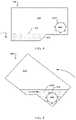
- FIG. 1depicts an example of a treadmill 100 having a deck 102 with a first pulley disposed in a front portion of the deck 102 and a second pulley incorporated into a rear portion of the deck 102 .
- a tread belt 104surrounds the first pulley and the second pulley.
- a motoris in mechanical communication with either the first pulley or the second pulley.
- a motor(not shown) drives the tread belt 104 .
- the deck 102With the deck 102 oriented in a substantially horizontal position, a user's body weight pushes the underside of the tread belt 104 into the deck's upper surface, which generates an amount of friction between the belt and the deck, which increases the load on the motor. Additionally, the tread belt carries the portion of the user's weight along the length of the deck as the motor operates, which also increases the load on the motor.
- the rear portion of the deck 102is attached to a base member 106 of the treadmill's frame 108 .
- a pivot connection 110 between the rear portion of the deck 102 and the base member 106allows the front portion of the deck 102 to incline upwards or decline downwards. When the deck 102 inclines or declines, the base member 106 remains stationary.
- a first side post 112is attached to a first side of the base member 106
- a second side post 114is attached to a second side of the base member 106 .
- the first side post 112 and the second side post 114also remain stationary as the deck 102 inclines and/or declines.
- the first side post 112 and the second side post 114collectively support a console 116 .
- the console 116includes a display 118 and an input mechanism 120 for controlling the deck's incline angle.
- FIG. 2depicts an example of a treadmill 200 .
- the deck 202is inclined so that the front portion of the deck 202 is elevated.
- the usercan perform an exercise on the deck 202 .
- gravitypulls on the user's mass, which offsets at least some of the mechanical load on the motor for driving the tread belt as the user pushes against the tread belt during the performance of an exercise.
- the power supplied to the motoris reduced accordingly to slow the tread belt and keep the tread belt traveling at the desired, consistent speed. Under these conditions, the tread belt is still traveling at the output speed that is consistent with the amount of electricity supplied to the motor because the amount of electricity supplied is reduced to be consistent with the reduced mechanical load.
- the user's body weightapplies a force sufficiently large that the motor receives a minimal amount of electrical power to keep the tread belt operating at the output speed.
- the summation of the angle of the deck, the weight of the user, the friction between the tread belt and the deck, other factors, or combinations thereofcause the drive shaft's motor to rotate at a faster speed than the output speed of the motor.
- This conditioncan be referred to as a runaway condition. While this example is described as a runaway condition, in other case, the runaway condition can be caused by a different set of circumstances.
- the runaway conditioncan cause the motor to generate electrical power and/or cause damage to the motor or other components of the treadmill.
- FIG. 3illustrates an example of a treadmill 302 with a portion of the housing removed for illustrative purposes.
- a drive motor 304is disposed adjacent to a pulley 306 that moves the tread belt 308 in a rotational direction.
- the drive motor 304is attached to the pulley 306 with a drive shaft.
- a power supply(not shown) supplies power to the motor to drive the rotation of the drive shaft.
- the power supplycan be an external source, such as an alternating current system incorporated into a residence or other building, a generator, an alternative power source, another type power source, or combinations thereof. In some instances, the power supply can be internal to the housing and/or treadmill 302 .
- Attached to and coaxial with the drive motor 304is a flywheel 310 .
- the flywheel 310rotates with the drive motor 304 .
- a lift motor 314is connected to the deck 316 and also to the base frame (not shown) of the treadmill. When activated, the lift motor 314 causes a rod to extend downward, which pushes against the front portion of the deck and the base frame causing the front portion of the deck to raise. In other situations, when the lift motor 314 is activated, the rod is retracted, which causes the front portion of the deck to lower. In these cases, the lift motor 314 can be transversely oriented with respect to the fan assembly 312 . While this example has been described as having a lift motor as part of a system for inclining the deck, any appropriate mechanism can be used to incline the deck.
- FIG. 4depicts an example of a runaway mitigation mechanism 400 .
- the runaway mitigation mechanism 400includes a container 402 and a portion of the drive shaft 404 is partially disposed within the container 402 .
- the container 402includes a fluid 406 , such as an oil-based or other viscous fluid.
- the container 402moves with the deck. When the deck is in a level orientation, the container is held at a corresponding orientation. On the other hand, when the deck is inclined at an angle, the container 402 is held in a tilted orientation.
- the fluid 406resides under the drive shaft 404 without making contact with the drive shaft 404 .
- the container 402includes a trough 408 defined in the far portion 410 of the container 402 where the fluid 406 can pool away from the drive shaft 404 . In alternative embodiments, no trough is included.
- At least one vane 412is attached to the drive shaft 404 . While this example has been depicted with a vane, any appropriate number or shape of vanes can be incorporated into the drive shaft 404 .
- FIG. 5depicts an example of a runaway mitigation mechanism 500 where the container 502 is oriented in a tilted orientation.
- the fluid 504pools in the proximity of the drive shaft 506 so that the fluid 504 is in contact with the drive shaft 506 .
- the drive shaft 506is immersed in the fluid 504 so that an entire circumference of the drive shaft 506 is in contact with the fluid 504 .
- the contact with the drive shaft 506resists rotation of the drive shaft 506 .
- the viscosity of the fluid 504resists the movement of the vanes 508 .
- FIG. 6depicts an example of a runaway mitigation mechanism 600 .
- a drive shaft 602extends beyond a motor casing 604 , and a rotary disc 606 is rigidly attached to the drive shaft 602 .
- a compression brake 608is positioned adjacent to the rotary disc 606 .
- the compression brake 608includes a first pad 610 adjacent a first side of the rotary disc 606 , and a second pad 614 adjacent a second side of the rotary disc 606 . When activated, the first pad 610 and the second pad 614 move towards the rotary disc 606 simultaneously and apply a compressive load to the rotary disc 606 which resists rotational movement of the rotary disc 606 .
- the compression brake 608applies a compressive load that is sufficient to prevent the rotary disc 606 , and therefore the drive shaft 602 , from rotating at all. Under other conditions, the compression brake 608 can apply a compressive load that merely increases the resistance to the rotational movement of the rotary disc 606 , but is not sufficient to stop the drive shaft 602 from rotating. When a runaway condition is sensed or at least determined to exist, the compression brake 608 can be activated to increase the mechanical resistance to the motor to at least mitigate the runaway condition.
- FIG. 7depicts an example of a runaway mitigation mechanism 700 .
- a drive shaft 702extends beyond a motor casing 704 , and a rotary disc 706 is rigidly attached to the drive shaft 702 .
- the rotary disc 706includes at least some magnetically conductive material.
- a magnetic unit 708is positioned adjacent to the rim 710 of the rotary disc 706 . The magnetic unit 708 can apply a magnetic force on the rotary disc 706 that resists movement of the rotary disc 706 and therefore movement of the drive shaft 702 .
- the magnetic unit 708is positionable with a linear actuator 712 .
- the linear actuator 712includes an actuator motor 714 and a screw rod 716 .
- the screw rod 716moves the magnetic unit 708 in a direction towards the rotary disc 706 .
- the screw rod 716moves the magnetic unit 708 in another direction away from the rotary disc 706 .
- the magnetic load applied to the rotary disc 706increases so that more resistance is applied to the rotary disc's movement and mechanical resistance on the motor increases.
- the magnetic unit 708moves away from the rotary disc 706 , the magnetic load on the rotary disc 706 decreases, which lowers mechanical resistance on the motor.
- the magnetic unitis an electromagnet that produces a magnetic field that is proportional to the power supplied to the magnetic unit.
- the magnetic strength applied to the rotary discis adjustable by varying the power to the magnetic unit.
- FIG. 8illustrates a perspective view of an example of a runaway mitigation system 800 in accordance with the present disclosure.
- the runaway mitigation system 800can include a combination of hardware and programmed instructions for executing the functions of the runaway mitigation system 800 .
- the runaway mitigation system 800includes processing resources 802 that are in communication with memory resources 804 .
- Processing resources 802include at least one processor and other resources used to process the programmed instructions.
- the memory resources 804represent generally any memory capable of storing data such as programmed instructions or data structures used by the runaway mitigation system 800 .
- the programmed instructions and data structures shown stored in the memory resources 804include an incline determiner 806 , a belt speed determiner 808 , a resistor thermometer 810 , and a resistance determiner 812 .
- I/O resources 814are in communication with the processing resources 802 .
- the I/O resources 814can include any appropriate type of mechanism for communicating with remote devices.
- the I/O resources 814can include a transmitter, a wireless transmitter, a receiver, a transceiver, a port for receiving an external memory, a network interface, another I/O resource, or combinations thereof.
- the I/O resourcescan be in communication with any appropriate device.
- the I/O resources 814are in communication with an incline sensor 816 , an odometer 818 , a thermometer 820 , a motor 822 , another remote device 824 , a runaway mitigation mechanism 826 , or combinations thereof.
- These remote devicescan be located on the treadmill, can be independent of the treadmill, can be in communication with the I/O resources over a network, can be part of a wearable device, or combinations thereof.
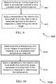
- FIG. 9shows a flowchart illustrating a method 900 for mitigating a runaway condition.
- the operations of method 900can be implemented by a runaway mitigation system or its components as described herein.
- a runaway mitigation systemcan execute a set of codes to control the functional elements of the device to perform the functions described below. Additionally or alternatively, the runaway mitigation system can perform aspects the functions described below using special-purpose hardware.
- an incline angle of the deck of an exercise machineis determined to be at a predetermined incline threshold.
- a resistanceis applied to the rotation of a drive shaft of a motor that drives a tread belt secured to the deck in response to determining the incline angle.
- FIG. 10shows a flowchart illustrating a method 1000 for mitigating a runaway condition.
- the operations of method 1000can be implemented by a runaway mitigation system or its components as described herein.
- a runaway mitigation systemcan execute a set of codes to control the functional elements of the device to perform the functions described below. Additionally or alternatively, the runaway mitigation system can perform aspects the functions described below using special-purpose hardware.
- a temperature of a dump resistor incorporated into a treadmillis determined to be at a predetermined temperature threshold.
- a resistanceis applied to the rotation of a drive shaft of a motor that drives movement of a tread belt of the treadmill in response to determining the temperature.
- FIG. 11depicts an example of a treadmill 302 with a portion of the housing removed for illustrative purposes.
- a drive motor 304is disposed adjacent to a pulley 306 that moves the tread belt 308 in a rotational direction.
- the drive motor 304is attached to the pulley 306 with a drive shaft.
- a power supply(not shown) supplies power to the drive motor 304 to drive the rotation of the drive shaft.
- Attached to and coaxial with the drive motor 304is a flywheel 310 .
- the flywheel 310rotates with the drive motor 304 .
- a lift motor 314is connected to the deck 316 and also to the base frame (not shown) of the treadmill.
- a cooling fan 320is located within the housing and is adjacent to the drive motor 304 and flywheel 310 . The cooling fan 320 is positioned to direct an airflow over the drive motor 304 and or lift motor.
- FIG. 12depicts an example of a housing 1200 incorporated into a treadmill deck.
- the housing 1200includes a drive motor 1202 , a dump resistor 1204 , and a cooling fan 1206 .
- the dump resistor 1204 and the cooling fan 1206can both draw on the electrical power generated by the drive motor 1202 .
- the dump resistor 1204 and the cooling fan 1206can dissipate the electrical power generated by the drive motor 1202 .
- the systems and methods disclosed hereincan provide users with an exercise machine that mitigates the effects of motor runaway. Not all commercial treadmills experience motor runaway due to a deck incline angle. However, in some cases where the treadmill deck inclines at a steeper angle than the industry's conventional treadmills do, the mechanical load on the treadmill motor can drop to a point where the motor that drives the tread belt experiences a runaway condition. In some situations, a runaway condition can result in the motor producing electricity. This electricity has to be directed somewhere, and in some cases, the runaway electricity is directed to a dump resistor where the excess electricity is converted to heat. This excess heat can raise the temperature of other components in the treadmill, which can reduce their useful life.
- the load on the motorcan be affected by multiple factors, such as the weight of the user, the angle of the deck, the friction between the tread belt and the deck's platform, the friction of the pulleys, the weight of the pulleys, the weight of the tread belt, other factors, or combinations thereof.
- the angle of the treadmill's deckis substantially horizontal, the tread belt moves the user along the length of the deck.
- the angle of the deckinclines, the user's mass interacts with gravity and pushes down on the tread belt as the user performs an exercise.
- the legapplies a downward force on the tread belt which helps move the tread belt along in the same direction that the motor is driving the tread belt.
- the amount of force that contributes to the movement of the tread belt from the userdepends in part on how hard the user applies the force and also the steepness of the incline angle. As a general rule, the steeper the incline angle, the more force that the user applies due to gravity pulling on the user. The weight of the user also affects the load to the tread belt as a heavier user can apply a greater load to the tread belt.
- the electrical load on the motorcan be reduced to keep the tread belt moving at the desired speed.
- the weight of the usercan cause the tread belt to move faster than the speed that the motor would otherwise run given the power load and the angle. In these cases, the motor can generate electricity as part of a runaway condition.
- a runaway mitigation mechanismcan apply an increased load on the motor, which can result in mitigating and/or eliminating the runaway condition.
- mitigating the runaway conditionthe amount of electricity produced by the motor can be reduced or entirely eliminated.
- the treadmillcan include a frame, a deck attached to the frame, and a tread belt incorporated into the deck.
- the framecan include a base portion that supports the deck on a support surface, such as a floor.
- a front pulleycan be connected to a front portion of the deck, and a rear pulley can be connected to a rear portion of the deck.
- a tread beltsurrounds the front pulley and the second pulley.
- a motorcan drive either the front pulley or the rear pulley and cause the tread belt to move along a surface of the deck.
- the speed of the tread beltcan be adjustable based on the motor's output. In some cases, the user can select the tread belt's speed through an input incorporated into the treadmill.
- the treadmillincludes an incline mechanism that is integrated into the base and controls an elevation of the front portion of the deck.
- the rear portion of the deckis connected to the base at a pivot connection.
- the incline mechanismchanges the elevation of the front portion of the deck, the rear portion of the deck remains connected to the base, thus, the front portion of the deck inclines with respect to the base.
- the treadmillincludes an upright structure that is connected to the base.
- the upright structureincludes a first post and a second post.
- the first post and the second postcan include a console.
- the consolecan include an input mechanism that controls an operational parameter of the treadmill.
- the consoleincludes a cooling mechanism (e.g. fan), speakers, microphones, sensors, other features, or combinations thereof.
- the consoleincludes a display.
- the motoris located inside of a housing.
- the drive motorcan be disposed adjacent to a pulley that moves the tread belt in a rotational direction.
- the drive motorcan be attached to the pulley with a drive shaft.
- a power supplycan provide power to the motor to drive the rotation of the drive shaft.
- the power supplycan be an external source, such as an alternating current system incorporated into a residence or other building, a generator, an alternative power source, another type power source, or combinations thereof.
- the power supplycan be internal to the housing and/or treadmill.
- a flywheelis attached to and coaxial with the drive motor. The flywheel can rotate with the drive motor.
- a lift motorcan be connected to the deck and to the base frame of the treadmill. When activated, the lift motor can cause a rod to extend downward, which pushes against the front portion of the deck and the base frame causing the front portion of the deck to raise. In other situations, when the lift motor can be activated, the rod is retracted, which causes the front portion of the deck to lower. In these cases, the lift motor can be transversely oriented with respect to the fan assembly. While this example has been described with having a lift motor as part of a system for inclining the deck, any appropriate mechanism can be used to incline the deck.
- the console displaycan depict information about the user, the operational parameters of the treadmill, entertainment, other features, or combinations thereof.
- the exercise machinecan be less expensive to manufacture, move, set up, transport, or combinations thereof.
- the exercise machinecan collect data about the user's physiological condition during the performance of an exercise.
- sensorsare incorporated into the exercise machine to gather specific types of physiological information about the user. These sensors can be located on the exercise machine where the user comes into contact with the exercise machine.
- an electrical contact that is part of a heart rate monitoring systemcan be incorporated into hand rails, handles, or other types of supports incorporated into the exercise machine.
- the electrical contactscan detect electrical pulses transmitted through the user's body during the exercise, and these measurements can be used to determine the user's heart rate.
- a runaway conditioncan be determined through any appropriate mechanism.
- a current measuring devicecan determine if electricity is being generated by the motor. In those circumstances where the electricity is being generated by the motor, the processing resources can determine that a runaway condition exists. Any appropriate type of device to measure the amount of power produced by the motor can be used. In some examples, an ohmmeter, an ammeter, a multimeter, a capacitor, another type of measurement device, or combinations thereof can be used. In some cases, any electricity that is generated can be directed to a dump resistor where the electricity is converted to heat. A thermometer can be used to measure the dump resistor's temperature. In those cases where the thermometer records that the dump resistor's temperature is above a baseline temperature, the processing resources can determine that a runaway condition exists.
- a runaway conditioncan be presumed when the incline of the deck is above a certain threshold. While other factors can affect when a runaway condition exists, like the user's weight, the sensing electronics can be simplified by presuming that a runaway condition exists solely based on the deck's incline angle.
- the processing resourcescan determine that a runaway condition exists. In this type of example, the mechanical resistance on the motor can be increased regardless of whether an actual runaway condition exists or not. In other circumstances, the processing resources can initiate additional tests when a presumption of a runaway condition exists and initiate a runaway mitigation procedure in response to the findings of those tests.
- the user's weightis known to the processing resources or at least determinable.
- the usercan input his or her weight into an input mechanism incorporated into the console or through a remote device in communication with the treadmill.
- the weight of the usercan determine which incline angle is classified as a runaway condition threshold angle.
- the requested speed of the tread beltalso affects which incline angle is classified as a runaway condition threshold angle.
- a rotary sensoris associated with the drive shaft, a flywheel, a pulley, another rotary device, or combinations thereof that determine how fast these components are operating.
- the speed that the motor should be running based on the amount of electricity inputted into the motorcan be compared with the actual speed of the motor to determine whether a runaway condition exists.
- the motoris determined to be in a runaway condition if the angle the incline deck is above a predetermined threshold angle.
- this predetermined threshold angleis adjustable based on the weight of the user, the inputted speed for the tread belt to move, other factors, or combinations thereof.
- the motorwhen the drive motor is in a runaway condition, the motor produces electrical power. In some instances, the electrical power is directed to a runaway load component. In some cases, the runaway load component is a dump resistor, which converts the electrical power to heat. In other examples, the runaway load component is a cooling fan, a message mechanism that alerts the user to the situation, a magnetic mechanism that increases a magnetic flux on a device that increases a resistance to move the treadmill or another object, a light, a speaker, a wireless profile mechanism, another device, or combinations thereof.
- the runaway load componentis a dump resistor, which converts the electrical power to heat.
- the runaway load componentis a cooling fan, a message mechanism that alerts the user to the situation, a magnetic mechanism that increases a magnetic flux on a device that increases a resistance to move the treadmill or another object, a light, a speaker, a wireless profile mechanism, another device, or combinations thereof.
- the runaway load componentis a cooling fan
- any appropriate type of cooling fancan be used.
- the cooling fanis a centrifugal fan, a cross-flow fan, an axial flow fan, and other type of fan or combinations thereof.
- a fanbe integrated into the flywheel that is attached to the drive motor. In those situation, the cooling fan can further contribute to the cooling of the housing.
- the cooling fancan be located at any appropriate location. In some cases, the cooling fan is located in the same housing as the drive motor. In other examples, the cooling fan is disposed in another housing that contains components other than the drive motor. In yet other cases, the drive motor is not disposed within a housing. In one example, the cooling fan is incorporated into the console of the treadmill's upright structure and is positioned to direct an airflow towards a user performing an exercise on the treadmill. The cooling fan can be located and oriented to direct an airflow over other components of the treadmill and/or user.
- the cooling fancan be positioned and oriented to cool a lift motor, a drive motor, a bearing, a battery, a dump resistor, a pulley, a user, an ambient environment, a user's hand, another user body part, a user's water bottle, another treadmill component, another component, or combinations thereof.
- the cooling fancan be located within the same housing in which the drive motor, lift motor, or another motor is located. In some cases, these motors or other devices are heat sensitive, and the cooling fan can cool the components within the housing. In those situations where the electricity generated by the drive motor is directed to a dump resistor when a runaway condition exists, the cooling fan can be directed to cool the dump resistor. In some cases, the cooling fan and the dump resistor both draw power from the drive motor. In some of these situations, the cooling fan can draw the entire amount of electricity provided from the drive motor. As more electricity is generated, the cooling fan can increase its rotational speed, thereby drawing on the larger amount of electricity. As the amount of electricity continues to increase even more, the cooling fan cannot use any more electricity. At that point, the extra amount of electricity can flow to the dump resistor. In alternative examples, the dump resistor and cooling fan can both draw from the drive motor even if just a small amount of electricity is produced.
- the runaway mitigation systemcan include a combination of hardware and programmed instructions for executing the functions of the runaway mitigation system.
- the runaway mitigation systemincludes processing resources that are in communication with memory resources.
- Processing resourcesinclude at least one processor and other resources used to process the programmed instructions.
- the memory resourcesrepresent generally any memory capable of storing data such as programmed instructions or data structures used by the runaway mitigation system.
- the programmed instructions and data structures shown stored in the memory resourcesinclude an incline determiner, a belt speed determiner, a resistor thermometer, and a resistance determiner.
- I/O resourcesare in communication with the processing resources.
- the I/O resourcescan include any appropriate type of mechanism for communicating with remote devices.
- the I/O resourcescan include a transmitter, a wireless transmitter, a receiver, a transceiver, a port for receiving an external memory, a network interface, another I/O resource, or combinations thereof.
- the I/O resourcescan be in communication with any appropriate device.
- the I/O resourcesare in communication with an incline sensor, an odometer, a thermometer, a motor, another remote device, a runaway mitigation mechanism, or combinations thereof.
- These remote devicescan be located on the treadmill, can be independent of the treadmill, can be in communication with the I/O resources over a network, can be part of a wearable device, or combinations thereof.
- Such protocolscan include standard wireless protocols, protocols used by Bluetooth® technologies, Wi-Fi protocols, Z-wave protocols, Zigbee protocols, other types of wireless protocols, or combinations thereof.
- the processing resourcescan include more or more processors.
- the processing resourcescan include an intelligent hardware device, (e.g., a general-purpose processor, a digital signal processor (DSP), a central processing unit (CPU), a microcontroller, an application specific integrated circuit (ASIC), a field-programmable gate array (FPGA), a programmable logic device, a discrete gate or transistor logic component, a discrete hardware component, or any combination thereof).
- the processing resourcescan be configured to operate a memory array using a memory controller.
- a memory controllercan be integrated into the processor.
- the processing resourcescan be configured to execute computer-readable instructions stored in a memory to perform various functions (e.g., function or tasks supporting overlaying exercise information on a remote display).
- An I/O controllercan manage input and output signals for the runaway mitigation system and/or the exercise machine. Input/output control components can also manage peripherals not integrated into these devices. In some cases, the input/output control component can represent a physical connection or port to an external peripheral. In some cases, I/O controller can utilize an operating system such as iOS®, ANDROID®, MS-DOS®, MS-WINDOWS®, OS/2®, UNIX®, LINUX®, or another known operating system.
- an operating systemsuch as iOS®, ANDROID®, MS-DOS®, MS-WINDOWS®, OS/2®, UNIX®, LINUX®, or another known operating system.
- Memory resourcescan include random access memory (RAM) and read only memory (ROM).
- RAMrandom access memory
- ROMread only memory
- the memorycan store computer-readable, computer-executable software including instructions that, when executed, cause the processor to perform various functions described herein.
- the memory resourcescan contain, among other things, a Basic Input-Output system (BIOS) which can control basic hardware and/or software operation such as the interaction with peripheral components or devices.
- BIOSBasic Input-Output system
- the incline determinerrepresents programmed instructions that, when executed, cause the processor to determine the incline of the treadmill deck.
- the incline determinerrequests the angle from a distance sensor, from a level sensor, from a gravity sensor, from an accelerometer, from another type of sensor, or combinations thereof.
- the sensorcan send raw data to the incline determiner where the raw data is interpreted to determine the incline angle.
- the incline determinerreceives data that is at least partially processed.
- the incline mechanism of the treadmillis in communication with the incline determiner. The incline mechanism can know the incline angle at which it has set the deck and can continuously send, periodically send, or send on demand information about the angle to the incline determiner.
- the belt speed determinerrepresents programmed instructions that, when executed, cause the processor to determine the speed that the tread belt is moving.
- the speed determinerrequests the angle from an odometer, optical sensor, an accelerometer, another type of sensor, or combinations thereof.
- the sensorcan send raw data to the incline determiner where the raw data is interpreted to determine the tread belt speed.
- the belt speed determinerreceives data that is at least partially processed.
- the resistor thermometerrepresents programmed instructions that, when executed, cause the processor to determine a temperature of at least one component of the treadmill that is indicative of a runaway condition.
- the resistor thermometercan measure the temperature of a dump resistor that is in electrical communication with the motor. In those conditions where the motor is in a runaway condition, the motor can be generating electricity and the generated electricity can be directed to the dump resistor to convert this electricity into heat. Under those circumstances where the dump resistor's temperature is above a predetermined threshold, the processor can determine that a runaway condition exists.
- the resistance determinerrepresents programmed instructions that, when executed, cause the processor to determine a resistance load on the motor.
- the resistance determinercan take inputs from the incline determiner, the belt speed determiner, the resistance thermometer, a user weight input, an inputted tread belt speed, an actual tread belt speed, other information, or combinations thereof.
- the resistance determinermeasures the speed inputted into the console by the user to operate the tread belt (inputted speed).
- the inputted speedcan be compared to the actual speed determined by the belt speed determiner or through another mechanism. If the actual speed and the inputted speed do not match, the resistance determiner can conclude that the resistance on the motor is too low to prevent a runaway condition or the processor can determine that a runaway condition exists.
- the resistance determinercan determine that an insufficient load exists on the motor to prevent a runaway condition when the temperature of the resistor is above a predetermined temperature threshold. In other examples, the resistance determiner can determine that an insufficient amount of resistance exists on the motor when the incline deck is orientated at an angle above a predetermined threshold angle.
- sensors incorporated into the treadmillare used to determine the existence of a runway condition.
- sensors or information from a remote devicecan at least contribute to determining whether a runaway condition exists.
- the treadmillcan include a runaway mitigation mechanism.
- the runaway mitigation mechanismis an active mechanism that operates in response to a determination that a runaway condition exists or is at least approaching a potential runaway condition.
- the active runaway mitigation mechanismcan respond by increasing the load on the motor.
- the runaway mitigation mechanismis a passive mechanism that automatically applies a greater resistance to the motor.
- the active runaway mitigation mechanismcan prevent a runaway condition from starting or can reduce, or even eliminate, the runaway condition.
- the active runaway condition mitigation mechanismcan include a braking mechanism, a compressive breaking mechanism, a hydraulic mechanism, a pneumatic mechanism, another type of mechanism, or combinations thereof that apply mechanical resistance to a rotation of the motor's drive shaft.
- a drive shaftextends beyond a motor casing, and a rotary disc is rigidly attached to the drive shaft.
- a compression brakecan be positioned adjacent to the rotary disc.
- the compression brakecan include a first pad adjacent a first side of the rotary disc, and a second pad adjacent a second side of the rotary disc. When activated, the first pad and the second pad move towards the rotary disc simultaneously and apply a compressive load to the rotary disc which resists rotational movement of the rotary disc. Under certain conditions, the compression brake can apply a compressive load that is sufficient to prevent the rotary disc, and therefore the drive shaft, from rotating at all.
- the compression brakecan apply a compressive load that merely increases the resistance to the rotational movement of the rotary disc, but is not sufficient to stop the drive shaft from rotating.
- the compression brakecan be activated to increase the mechanical resistance to the motor to at least mitigate the runaway condition.
- the rotary disccan include at least some magnetically conductive material.
- a magnetic unitcan be positioned adjacent to a rim of the rotary disc. The magnetic unit can apply a magnetic force on the rotary disc that resists movement of the rotary disc and therefore movement of the drive shaft.
- the magnetic unitcan be positionable with a linear actuator.
- the linear actuatorcan include an actuator motor and a screw rod.
- the screw rodmoves the magnetic unit in a direction towards the rotary disc.
- the screw rodmoves the magnetic unit in another direction away from the rotary disc.
- the magnetic load applied to the rotary disccan increase so that more resistance is applied to the rotary disc's movement and mechanical resistance on the motor increases.
- the magnetic load on the rotary disccan decrease, which lowers mechanical resistance on the motor.
- the magnetic unitis an electromagnet that produces a magnetic field that is proportional to the power supplied to the magnetic unit.
- the magnetic strength applied to the rotary discis adjustable by varying the power to the magnetic unit.
- the resistancecan be applied automatically without a command instruction to the motor under those circumstances when a runaway condition is more likely to occur.
- the increased resistance on the motorcan be automatically applied when the treadmill deck is inclined above a predetermined threshold angle.
- the mechanismincludes a container and a portion of the drive shaft is partially disposed within the container.
- the containerincludes a fluid, such as an oil-based fluid.
- the containermoves with the deck. So, when the deck is in a level orientation, the container is held at a corresponding orientation. On the other hand, when the deck is inclined at an angle, the container is held in a tilting orientation.
- the fluidIn the level orientation, the fluid resides under the drive shaft without making contact with the drive shaft. In the tilted orientation, the fluid can pool in the proximity of the drive shaft so that the fluid is in contact with the drive shaft. In the illustrated example, the drive shaft is immersed in the fluid so that an entire circumference of the drive shaft is in contact with the fluid. In some examples, the contact with the drive shaft resists rotation of the drive shaft. In some cases, the viscosity of the fluid resists the rotation of the shaft. In some cases, the shaft has a generally symmetric shape, and the surface friction of the cylindrical shape and the fluid increases the resistance to the rotation of the drive shaft.
- the drive shaftcan include features that increase the amount of resistance applied from at least partially immersion into the fluid.
- One feature that can increase the resistanceincludes at least one vane is attached to the drive shaft. The vane can push against the fluid as the drive shaft rotates thereby increasing the resistance to the rotation of the drive shaft. While this example has been depicted with a vane for increasing the resistance to the drive shaft's rotation, any appropriate type of feature that can increase the resistance can be incorporated into the drive shaft.
- a magnetcan come into closer proximity with the drive shaft as the deck is inclined. In this example, the closer that the magnet is to the drive shaft, the greater influence the magnet's flux has on the drive shaft resulting in a greater resistance to the rotation of the drive shaft.
- Information and signals described hereincan be represented using any of a variety of different technologies and techniques.
- data, instructions, commands, information, signals, bits, symbols, and chipsthat can be referenced throughout the above description can be represented by voltages, currents, electromagnetic waves, magnetic fields or particles, optical fields or particles, or any combination thereof.
- a general-purpose processorcan be a microprocessor, but in the alternative, the processor can be any conventional processor, controller, microcontroller, or state machine.
- a processorcan also be implemented as a combination of computing devices (e.g., a combination of a digital signal processor (DSP) and a microprocessor, multiple microprocessors, one or more microprocessors in conjunction with a DSP core, or any other such configuration).
- DSPdigital signal processor
- the functions described hereincan be implemented in hardware, software executed by a processor, firmware, or any combination thereof. If implemented in software executed by a processor, the functions can be stored on or transmitted over as one or more instructions or code on a computer-readable medium. Other examples and implementations are within the scope of the disclosure and appended claims. For example, due to the nature of software, functions described above can be implemented using software executed by a processor, hardware, firmware, hardwiring, or combinations of any of these. Features implementing functions can also be physically located at various positions, including being distributed so that portions of functions are implemented at different physical locations.
- Computer-readable mediaincludes both non-transitory computer storage media and communication media including any medium that facilitates transfer of a computer program from one place to another.
- a non-transitory storage mediumcan be any available medium that can be accessed by a general purpose or special purpose computer.
- non-transitory computer-readable mediacan include RAM, ROM, electrically erasable programmable read only memory (EEPROM), compact disk (CD) ROM or other optical disk storage, magnetic disk storage or other magnetic storage devices, or any other non-transitory medium that can be used to carry or store desired program code means in the form of instructions or data structures and that can be accessed by a general-purpose or special-purpose computer, or a general-purpose or special-purpose processor.
- RAMrandom access memory
- ROMread only memory
- EEPROMelectrically erasable programmable read only memory
- CDcompact disk
- magnetic disk storage or other magnetic storage devicesor any other non-transitory medium that can be used to carry or store desired program code means in the form of instructions or data structures
- any connectionis properly termed a computer-readable medium.
- the softwareis transmitted from a website, server, or other remote source using a coaxial cable, fiber optic cable, twisted pair, digital subscriber line (DSL), or wireless technologies such as infrared, radio, and microwave, then the coaxial cable, fiber optic cable, twisted pair, digital subscriber line (DSL), or wireless technologies such as infrared, radio, and microwave are included in the definition of medium.
- a portable mediuminclude CD, laser disc, optical disc, digital versatile disc (DVD), floppy disk and Blu-ray disc where disks usually reproduce data magnetically, while discs reproduce data optically with lasers. Combinations of the above are also included within the scope of computer-readable media.
Landscapes
- Health & Medical Sciences (AREA)
- Engineering & Computer Science (AREA)
- General Health & Medical Sciences (AREA)
- Physical Education & Sports Medicine (AREA)
- Cardiology (AREA)
- Vascular Medicine (AREA)
- Power Engineering (AREA)
- Mechanical Engineering (AREA)
- General Engineering & Computer Science (AREA)
- Orthopedic Medicine & Surgery (AREA)
- Biophysics (AREA)
- Life Sciences & Earth Sciences (AREA)
- Rehabilitation Tools (AREA)
Abstract
Description
Claims (20)
Priority Applications (1)
| Application Number | Priority Date | Filing Date | Title |
|---|---|---|---|
| US17/141,880US11511152B2 (en) | 2016-10-12 | 2021-01-05 | Systems and methods for reducing runaway resistance on an exercise device |
Applications Claiming Priority (5)
| Application Number | Priority Date | Filing Date | Title |
|---|---|---|---|
| US201662407073P | 2016-10-12 | 2016-10-12 | |
| US15/730,516US10207148B2 (en) | 2016-10-12 | 2017-10-11 | Systems and methods for reducing runaway resistance on an exercise device |
| US15/847,279US10376736B2 (en) | 2016-10-12 | 2017-12-19 | Cooling an exercise device during a dive motor runway condition |
| US16/508,827US10918905B2 (en) | 2016-10-12 | 2019-07-11 | Systems and methods for reducing runaway resistance on an exercise device |
| US17/141,880US11511152B2 (en) | 2016-10-12 | 2021-01-05 | Systems and methods for reducing runaway resistance on an exercise device |
Related Parent Applications (1)
| Application Number | Title | Priority Date | Filing Date |
|---|---|---|---|
| US16/508,827ContinuationUS10918905B2 (en) | 2016-10-12 | 2019-07-11 | Systems and methods for reducing runaway resistance on an exercise device |
Publications (2)
| Publication Number | Publication Date |
|---|---|
| US20210121736A1 US20210121736A1 (en) | 2021-04-29 |
| US11511152B2true US11511152B2 (en) | 2022-11-29 |
Family
ID=68290876
Family Applications (2)
| Application Number | Title | Priority Date | Filing Date |
|---|---|---|---|
| US16/508,827Active2037-11-14US10918905B2 (en) | 2016-10-12 | 2019-07-11 | Systems and methods for reducing runaway resistance on an exercise device |
| US17/141,880Active2037-11-06US11511152B2 (en) | 2016-10-12 | 2021-01-05 | Systems and methods for reducing runaway resistance on an exercise device |
Family Applications Before (1)
| Application Number | Title | Priority Date | Filing Date |
|---|---|---|---|
| US16/508,827Active2037-11-14US10918905B2 (en) | 2016-10-12 | 2019-07-11 | Systems and methods for reducing runaway resistance on an exercise device |
Country Status (1)
| Country | Link |
|---|---|
| US (2) | US10918905B2 (en) |
Cited By (15)
| Publication number | Priority date | Publication date | Assignee | Title |
|---|---|---|---|---|
| US11878199B2 (en) | 2021-02-16 | 2024-01-23 | Ifit Inc. | Safety mechanism for an adjustable dumbbell |
| US11951358B2 (en) | 2019-02-12 | 2024-04-09 | Ifit Inc. | Encoding exercise machine control commands in subtitle streams |
| US12005315B2 (en) | 2018-07-13 | 2024-06-11 | Ifit Inc. | Cycling shoe power sensors |
| US12023549B2 (en) | 2016-03-18 | 2024-07-02 | Ifit Inc. | Stationary exercise machine configured to execute a programmed workout with aerobic portions and lifting portions |
| US12029935B2 (en) | 2021-08-19 | 2024-07-09 | Ifit Inc. | Adjustment mechanism for an adjustable kettlebell |
| US12029961B2 (en) | 2020-03-24 | 2024-07-09 | Ifit Inc. | Flagging irregularities in user performance in an exercise machine system |
| US12176009B2 (en) | 2021-12-30 | 2024-12-24 | Ifit Inc. | Systems and methods for synchronizing workout equipment with video files |
| US12219201B2 (en) | 2021-08-05 | 2025-02-04 | Ifit Inc. | Synchronizing video workout programs across multiple devices |
| US12263371B2 (en) | 2021-04-27 | 2025-04-01 | Ifit Inc. | Devices, systems, and methods for rotating a tread belt in two directions |
| US12270441B2 (en) | 2017-12-09 | 2025-04-08 | Ifit Inc. | Systems and methods for selectively rotationally fixing a pedaled drivetrain |
| US12280294B2 (en) | 2021-10-15 | 2025-04-22 | Ifit Inc. | Magnetic clutch for a pedaled drivetrain |
| US12296247B2 (en) | 2019-10-11 | 2025-05-13 | Ifit Inc. | Modular exercise device |
| US12350573B2 (en) | 2021-04-27 | 2025-07-08 | Ifit Inc. | Systems and methods for cross-training on exercise devices |
| US12350547B2 (en) | 2022-02-28 | 2025-07-08 | Ifit Inc. | Devices, systems, and methods for moving a movable step through a transition zone |
| US12433815B2 (en) | 2020-10-02 | 2025-10-07 | Ifit Inc. | Massage roller with pressure sensors |
Families Citing this family (24)
| Publication number | Priority date | Publication date | Assignee | Title |
|---|---|---|---|---|
| WO2014153158A1 (en) | 2013-03-14 | 2014-09-25 | Icon Health & Fitness, Inc. | Strength training apparatus with flywheel and related methods |
| CN105848733B (en) | 2013-12-26 | 2018-02-13 | 爱康保健健身有限公司 | Magnetic resistance mechanism in hawser apparatus |
| US10433612B2 (en) | 2014-03-10 | 2019-10-08 | Icon Health & Fitness, Inc. | Pressure sensor to quantify work |
| US10940360B2 (en) | 2015-08-26 | 2021-03-09 | Icon Health & Fitness, Inc. | Strength exercise mechanisms |
| US10561894B2 (en) | 2016-03-18 | 2020-02-18 | Icon Health & Fitness, Inc. | Treadmill with removable supports |
| US10252109B2 (en) | 2016-05-13 | 2019-04-09 | Icon Health & Fitness, Inc. | Weight platform treadmill |
| US11058914B2 (en) | 2016-07-01 | 2021-07-13 | Icon Health & Fitness, Inc. | Cooling methods for exercise equipment |
| US10918905B2 (en)* | 2016-10-12 | 2021-02-16 | Icon Health & Fitness, Inc. | Systems and methods for reducing runaway resistance on an exercise device |
| US11451108B2 (en) | 2017-08-16 | 2022-09-20 | Ifit Inc. | Systems and methods for axial impact resistance in electric motors |
| CN111491700B (en) | 2017-12-22 | 2022-03-04 | 艾肯运动与健康公司 | tiltable exercise machine |
| US11000730B2 (en) | 2018-03-16 | 2021-05-11 | Icon Health & Fitness, Inc. | Elliptical exercise machine |
| EP3815226B1 (en) | 2018-06-11 | 2023-05-31 | iFIT Inc. | Increased durability linear actuator |
| USD918317S1 (en)* | 2018-10-01 | 2021-05-04 | Technogym S.P.A. | Exercise equipment |
| TWI761125B (en) | 2019-01-25 | 2022-04-11 | 美商愛康有限公司 | Interactive pedaled exercise device |
| US11298577B2 (en) | 2019-02-11 | 2022-04-12 | Ifit Inc. | Cable and power rack exercise machine |
| KR102231213B1 (en)* | 2019-04-12 | 2021-03-23 | 조현상 | Analyzing apparatus based on power consumption information of treadmill |
| WO2020236963A1 (en) | 2019-05-23 | 2020-11-26 | Icon Health & Fitness, Inc. | Systems and methods for cooling an exercise device |
| US11534651B2 (en) | 2019-08-15 | 2022-12-27 | Ifit Inc. | Adjustable dumbbell system |
| TWI750890B (en) | 2019-11-12 | 2021-12-21 | 美商愛康運動與健康公司 | Exercise storage system |
| US11458357B2 (en)* | 2019-12-10 | 2022-10-04 | Peloton Interactive, Inc. | Exercise system |
| US11931621B2 (en) | 2020-03-18 | 2024-03-19 | Ifit Inc. | Systems and methods for treadmill drift avoidance |
| WO2021195148A1 (en) | 2020-03-24 | 2021-09-30 | Icon Health & Fitness, Inc. | Leaderboard with irregularity flags in an exercise machine system |
| US12409375B2 (en) | 2022-03-18 | 2025-09-09 | Ifit Inc. | Systems and methods for haptic simulation in incline exercise devices |
| USD1019824S1 (en)* | 2023-10-31 | 2024-03-26 | Shenzhen Shenlaiyibi Technology Co., Ltd. | Treadmill |
Citations (44)
| Publication number | Priority date | Publication date | Assignee | Title |
|---|---|---|---|---|
| US3408067A (en)* | 1966-05-19 | 1968-10-29 | Raymond E. Armstrong | Sking simulator device |
| US3711812A (en)* | 1971-11-29 | 1973-01-16 | Del Mar Eng Lab | Drive and control system for diagnostic and therapeutic exercise treadmill |
| US4204673A (en)* | 1978-12-14 | 1980-05-27 | Speer John Sr | Dual-tread exerciser |
| US4423864A (en)* | 1981-10-13 | 1984-01-03 | Wiik Sven E | Angularly adjustable ski deck |
| US4733858A (en)* | 1986-05-23 | 1988-03-29 | Lan Chuang S | Multi-purpose exerciser |
| US4749181A (en)* | 1986-09-30 | 1988-06-07 | Pittaway James W | Motor-driven exercise apparatus having runaway prevention system |
| US5295927A (en)* | 1991-11-27 | 1994-03-22 | Fitness Master, Inc. | Stepper exercise machine |
| US5314390A (en)* | 1992-01-31 | 1994-05-24 | Loredan Biomedical, Inc. | Linear tracking programmable exerciser |
| US5330507A (en)* | 1992-04-24 | 1994-07-19 | Medtronic, Inc. | Implantable electrical vagal stimulation for prevention or interruption of life threatening arrhythmias |
| US5738611A (en)* | 1993-06-02 | 1998-04-14 | The Ehrenfried Company | Aerobic and strength exercise apparatus |
| US5830162A (en)* | 1992-01-23 | 1998-11-03 | Giovannetti; Giovanni Battista | Apparatus for the antigravity modification of the myotensions adapting the human posture in all of the planes of space |
| US6042513A (en)* | 1997-03-27 | 2000-03-28 | Minarik Corporation | Non destructive runaway protection for an electric motor |
| US6066163A (en)* | 1996-02-02 | 2000-05-23 | John; Michael Sasha | Adaptive brain stimulation method and system |
| US6095952A (en)* | 1999-05-13 | 2000-08-01 | Rensselaer Polytechnic Institute | Exercise device |
| US6132724A (en)* | 1998-04-29 | 2000-10-17 | City Of Hope National Medical Center | Allelic polygene diagnosis of reward deficiency syndrome and treatment |
| US6160955A (en)* | 1996-10-25 | 2000-12-12 | Ge Power Controls Italia S.P.A., Procund Elettronica Division | Control circuits of an apparatus for physical exercises |
| US6463328B1 (en)* | 1996-02-02 | 2002-10-08 | Michael Sasha John | Adaptive brain stimulation method and system |
| US20030064862A1 (en)* | 2001-09-28 | 2003-04-03 | Icon Ip, Inc. | Inclining tread apparatus |
| US6676569B1 (en)* | 1998-06-09 | 2004-01-13 | Scott Brian Radow | Bipedal locomotion training and performance evaluation device and method |
| US6880487B2 (en)* | 2001-04-05 | 2005-04-19 | The Regents Of The University Of California | Robotic device for locomotor training |
| US7125388B1 (en)* | 2002-05-20 | 2006-10-24 | The Regents Of The University Of California | Robotic gait rehabilitation by optimal motion of the hip |
| US20080020907A1 (en)* | 2006-04-18 | 2008-01-24 | Chin-Ta Lin | Mechanism Using a Single Power Source to Provide Two Exercising Functions for a Physical Exerciser |
| US7381163B2 (en)* | 2001-10-24 | 2008-06-03 | The Regents Of The University Of California | Closed-loop force controlled body weight support system |
| US20080176713A1 (en)* | 2006-12-05 | 2008-07-24 | Pablo Olivera Brizzio | Method and apparatus for selecting a condition of a fitness machine in relation to a user |
| US20080312048A1 (en)* | 2007-06-15 | 2008-12-18 | Cybex International, Inc. | Treadmill belt support assembly |
| US20090137367A1 (en)* | 2000-02-02 | 2009-05-28 | Icon Ip, Inc. | Inclining treadmill with magnetic braking system |
| US20090267348A1 (en)* | 2008-04-23 | 2009-10-29 | Raanan Liebermann | Alternative energy generation systems for vehicles |
| US7621850B2 (en)* | 2003-02-28 | 2009-11-24 | Nautilus, Inc. | Dual deck exercise device |
| US20100137105A1 (en)* | 2008-12-01 | 2010-06-03 | Mclaughlin Thomas | Riding the joystick system to health and fitness |
| US20100270810A1 (en)* | 2009-04-23 | 2010-10-28 | Raanan Liebermann | Alternative energy generation systems for vehicles |
| US20110031839A1 (en)* | 2009-06-02 | 2011-02-10 | Cedar Ridge Research, Llc. | System and Method for Energy Generation |
| US20130175132A1 (en)* | 2010-09-15 | 2013-07-11 | Inventus Engineering Gmbh | Magnetorheological transmission device |
| US20130211594A1 (en)* | 2012-02-15 | 2013-08-15 | Kenneth Dean Stephens, Jr. | Proxy Robots and Remote Environment Simulator for Their Human Handlers |
| US20140283728A1 (en)* | 2011-10-13 | 2014-09-25 | LiFeng Wang | Take-Off and Landing System for Carrier Aircraft on an Aircraft Carrier and the Method Thereof |
| US20150321337A1 (en)* | 2014-05-06 | 2015-11-12 | Kenneth Dean Stephens, Jr. | Enhanced Environment Simulator for Proxy Robot Handlers |
| US20160153508A1 (en)* | 2010-09-15 | 2016-06-02 | Inventus Engineering Gmbh | Magnetorheological transmission device |
| US20170027803A1 (en)* | 2014-04-21 | 2017-02-02 | The Trustees Of Columbia University In The City Of New York | Human Movement Research, Therapeutic, and Diagnostic Devices, Methods, and Systems |
| US20170129105A1 (en)* | 2012-03-21 | 2017-05-11 | Kenneth Dean Stephens, Jr. | Replicating the Remote Environment of a Proxy Robot |
| US9671316B2 (en)* | 2014-02-27 | 2017-06-06 | Gee Hoo Fitec Corporation | Testing system of exercise machine and method of remotely testing exercise machine |
| US20170221657A1 (en)* | 2014-08-05 | 2017-08-03 | Cord Safe Ltd | Motor kill switch arrangement |
| US20180085651A1 (en)* | 2016-09-02 | 2018-03-29 | True Fitness Technology, Inc. | Braking systems for exercise machines |
| US10207148B2 (en)* | 2016-10-12 | 2019-02-19 | Icon Health & Fitness, Inc. | Systems and methods for reducing runaway resistance on an exercise device |
| US10376736B2 (en)* | 2016-10-12 | 2019-08-13 | Icon Health & Fitness, Inc. | Cooling an exercise device during a dive motor runway condition |
| US20190329091A1 (en)* | 2016-10-12 | 2019-10-31 | Icon Health & Fitness, Inc. | Systems and methods for reducing runaway resistance on an exercise device |
Family Cites Families (499)
| Publication number | Priority date | Publication date | Assignee | Title |
|---|---|---|---|---|
| US3123646A (en) | 1964-03-03 | Primary acyclic amines | ||
| US683284A (en) | 1900-11-22 | 1901-09-24 | Albert A Honey | Electromagnetic brake. |
| US2743623A (en) | 1954-09-16 | 1956-05-01 | Lambert Engineering Company | Screw actuators |
| US3368746A (en) | 1965-12-06 | 1968-02-13 | Smith Corp A O | Air deflector for improved cooling of fan motor |
| US3579339A (en) | 1967-05-23 | 1971-05-18 | Du Pont | Photopolymerizable dispersions and elements containing nonmigratory photoreducible dyes |
| US4023795A (en) | 1975-12-15 | 1977-05-17 | Pauls Edward A | Cross-country ski exerciser |
| US4082267A (en) | 1976-05-12 | 1978-04-04 | Flavell Evan R | Bilateral isokinetic exerciser |
| US4300760A (en) | 1977-01-12 | 1981-11-17 | Harry Bobroff | Exercise device |
| US4334695A (en) | 1980-03-10 | 1982-06-15 | Walter Ashby | Walking buggy |
| US5202574A (en) | 1980-05-02 | 1993-04-13 | Texas Instruments Incorporated | Semiconductor having improved interlevel conductor insulation |
| USD286311S (en) | 1984-05-25 | 1986-10-21 | Pro Form, Inc. | Rowing machine |
| US4684126A (en) | 1984-08-29 | 1987-08-04 | Pro Form, Inc. | General purpose exercise machine |
| US4788493A (en) | 1984-12-04 | 1988-11-29 | Square D Company | Apparatus for detecting direction of electric power flow |
| US4728102A (en) | 1986-04-28 | 1988-03-01 | P.S.I. Nordic Track, Inc. | Resistance indicator for frictionally resistant exercise device |
| US4750736A (en) | 1986-05-05 | 1988-06-14 | Weslo, Inc. | Multipurpose exercise machine |
| US5108093A (en) | 1986-05-08 | 1992-04-28 | Weslo, Inc. | Multipurpose exerciser |
| US5622527A (en) | 1986-05-08 | 1997-04-22 | Proform Fitness Products, Inc. | Independent action stepper |
| US5135216A (en) | 1991-01-29 | 1992-08-04 | Proform Fitness Products, Inc. | Modular resistance assembly for exercise machines |
| US4813667A (en) | 1986-05-08 | 1989-03-21 | Weslo, Inc. | Multipurpose exerciser |
| US4796881A (en) | 1986-05-08 | 1989-01-10 | Weslo, Inc. | Multipurpose exercising apparatus |
| US5062627A (en) | 1991-01-23 | 1991-11-05 | Proform Fitness Products, Inc. | Reciprocator for a stepper exercise machine |
| US4830371A (en) | 1986-06-17 | 1989-05-16 | Grand Slam, Inc. | Ball hitting practice device |
| US4681318A (en) | 1986-06-17 | 1987-07-21 | Grand Slam, Inc. | Ball hitting practice device |
| USD306468S (en) | 1986-12-22 | 1990-03-06 | Weslo, Inc. | Treadmill exerciser |
| USD304849S (en) | 1986-12-29 | 1989-11-28 | Weslo, Inc. | Treadmill exerciser |
| USD306891S (en) | 1986-12-29 | 1990-03-27 | Weslo, Inc. | Treadmill exerciser |
| US5000443A (en) | 1987-09-08 | 1991-03-19 | Weslo, Inc. | Striding exerciser |
| US4850585A (en) | 1987-09-08 | 1989-07-25 | Weslo, Inc. | Striding exerciser |
| WO1989007473A1 (en) | 1988-02-16 | 1989-08-24 | Tunturi, Inc. | Modular exercise treadmill |
| US4938478A (en) | 1988-02-29 | 1990-07-03 | Lay William C | Ball hitting practice device |
| USD332347S (en) | 1988-03-29 | 1993-01-12 | Raadt Rita V | Needle container |
| USD309167S (en) | 1988-04-18 | 1990-07-10 | Weslo, Inc. | Exercise cycle |
| US4883272A (en) | 1988-05-02 | 1989-11-28 | Lay William C | Ball catching frame with ball expelling machine connected thereto |
| USD307615S (en) | 1988-06-02 | 1990-05-01 | Proform Fitness Products, Inc. | Exercise cycle |
| US4971316A (en) | 1988-06-02 | 1990-11-20 | Proform Fitness Products, Inc. | Dual action exercise cycle |
| USD307614S (en) | 1988-06-02 | 1990-05-01 | Proform Fitness Products, Inc. | Exercise cycle |
| US5000444A (en) | 1988-06-02 | 1991-03-19 | Proform Fitness Products, Inc. | Dual action exercise cycle |
| US4921242A (en) | 1988-07-20 | 1990-05-01 | Weslo, Inc. | Exercise apparatus resistance system |
| US4880225A (en) | 1988-07-28 | 1989-11-14 | Diversified Products Corporation | Dual action cycle exerciser |
| US4844451A (en) | 1988-07-29 | 1989-07-04 | Weslo, Inc. | Exercise cycle with locking mechanism |
| US5014980A (en) | 1988-07-29 | 1991-05-14 | Proform Fitness Products, Inc. | Exercise cycle with locking mechanism |
| US4913396B2 (en) | 1988-10-12 | 1995-06-20 | Weslo Inc | Adjustable incline system for exercise equipment |
| US5192255B1 (en) | 1988-10-12 | 1995-01-31 | Citicorp North America Inc | Adjustable incline system for exercise equipment |
| US5029801A (en) | 1988-10-12 | 1991-07-09 | Proform Fitness Products, Inc. | Adjustable incline system for exercise equipment |
| USD309485S (en) | 1988-12-21 | 1990-07-24 | Weslo, Inc. | Exercise cycle |
| USD318086S (en) | 1988-12-27 | 1991-07-09 | Proform Fitness Products, Inc. | Exercise cycle |
| US5171196A (en) | 1989-01-03 | 1992-12-15 | Lynch Robert P | Treadmill with variable upper body resistance loading |
| USD310253S (en) | 1989-01-12 | 1990-08-28 | Proform Fitness Products, Inc. | Exercise cycle |
| US4932650A (en) | 1989-01-13 | 1990-06-12 | Proform Fitness Products, Inc. | Semi-recumbent exercise cycle |
| US4955599A (en) | 1989-01-19 | 1990-09-11 | Proform Fitness Products, Inc. | Exercise cycle with gear drive |
| USD316124S (en) | 1989-01-19 | 1991-04-09 | Weslo, Inc. | Treadmill with siderail |
| US5102380A (en) | 1989-02-01 | 1992-04-07 | Proform Fitness Products, Inc. | Cooling exercise treadmill |
| US5013033A (en) | 1989-02-01 | 1991-05-07 | Proform Fitness Products, Inc. | Rowing apparatus |
| USD318699S (en) | 1989-02-01 | 1991-07-30 | Jacobson David L | Treadmill |
| US5512025A (en) | 1989-02-03 | 1996-04-30 | Icon Health & Fitness, Inc. | User-programmable computerized console for exercise machines |
| US5062632A (en) | 1989-12-22 | 1991-11-05 | Proform Fitness Products, Inc. | User programmable exercise machine |
| US5104120A (en) | 1989-02-03 | 1992-04-14 | Proform Fitness Products, Inc. | Exercise machine control system |
| USD315765S (en) | 1989-02-03 | 1991-03-26 | Proform Fitness Products, Inc. | Treadmill |
| US5067710A (en) | 1989-02-03 | 1991-11-26 | Proform Fitness Products, Inc. | Computerized exercise machine |
| US4998725A (en) | 1989-02-03 | 1991-03-12 | Proform Fitness Products, Inc. | Exercise machine controller |
| USD313055S (en) | 1989-03-21 | 1990-12-18 | Proform Fitness Products, Inc. | Exercise cycle console |
| USD318085S (en) | 1989-05-12 | 1991-07-09 | Proform Fitness Products, Inc. | Treadmill housing |
| CA2018219C (en) | 1989-06-19 | 1998-03-24 | Richard E. Skowronski | Exercise treadmill |
| US4979737A (en) | 1989-07-06 | 1990-12-25 | Kock Ronald W | Apparatus for exercising lower leg muscles |
| USD323863S (en) | 1989-09-07 | 1992-02-11 | Proform Fitness Products, Inc. | Stationary exercise cycle |
| US5259611A (en) | 1989-11-01 | 1993-11-09 | Proform Fitness Products, Inc. | Direct drive controlled program system |
| US5016871A (en) | 1989-11-01 | 1991-05-21 | Proform Fitness Products, Inc. | Exercise machine resistance controller |
| US5058882A (en) | 1990-02-20 | 1991-10-22 | Proform Fitness Products, Inc. | Stepper exerciser |
| US5190505A (en) | 1989-11-06 | 1993-03-02 | Proform Fitness Products, Inc. | Stepper exerciser |
| USD321388S (en) | 1989-11-06 | 1991-11-05 | Proform Fitness Products, Inc. | Stepping exercise machine |
| USD323198S (en) | 1990-01-31 | 1992-01-14 | Proform Fitness Products, Inc. | Treadmill exerciser |
| USD323009S (en) | 1990-01-31 | 1992-01-07 | Proform Fitness Products, Inc. | Treadmill exerciser |
| USD326491S (en) | 1990-01-31 | 1992-05-26 | Dalebout William T | Stepping exercise machine |
| USD323199S (en) | 1990-01-31 | 1992-01-14 | Proform Fitness Products, Inc. | Treadmill exerciser |
| US5279528A (en) | 1990-02-14 | 1994-01-18 | Proform Fitness Products, Inc. | Cushioned deck for treadmill |
| US5088729A (en) | 1990-02-14 | 1992-02-18 | Weslo, Inc. | Treadmill frame and roller bracket assembly |
| US5247853A (en) | 1990-02-16 | 1993-09-28 | Proform Fitness Products, Inc. | Flywheel |
| US4981294A (en) | 1990-02-16 | 1991-01-01 | Proform Fitness Products, Inc. | Exercise machines with dual resistance means |
| US4974832A (en) | 1990-02-16 | 1990-12-04 | Proform Fitness Products, Inc. | Rower slant board |
| US5203826A (en) | 1990-02-16 | 1993-04-20 | Proform Fitness Products, Inc. | Enclosed flywheel |
| US5034576A (en) | 1990-02-20 | 1991-07-23 | Proform Fitness Products, Inc. | Console switch |
| US5149084A (en) | 1990-02-20 | 1992-09-22 | Proform Fitness Products, Inc. | Exercise machine with motivational display |
| US5000442A (en) | 1990-02-20 | 1991-03-19 | Proform Fitness Products, Inc. | Cross country ski exerciser |
| US5062626A (en) | 1990-02-20 | 1991-11-05 | Proform Fitness Products, Inc. | Treadmill speed adjustment |
| US5058881A (en) | 1990-02-20 | 1991-10-22 | Proform Fitness Products, Inc. | Exercise machine height adjustment foot |
| US5302161A (en) | 1990-03-28 | 1994-04-12 | Noordictrack, Inc. | Flexible line guidance and tension measuring device |
| US5090694A (en) | 1990-03-28 | 1992-02-25 | Nordictrack, Inc. | Combination chair and exercise unit |
| US5147265A (en) | 1990-03-28 | 1992-09-15 | Nordictrack, Inc. | Rotation-activated resistance device |
| US5195937A (en) | 1990-03-28 | 1993-03-23 | Nordictrack, Inc. | Multi-exercise apparatus |
| US5072929A (en) | 1990-06-13 | 1991-12-17 | Nordictrack, Inc. | Dual resistance exercise rowing machine |
| AU8337491A (en) | 1990-08-31 | 1992-03-30 | Nordictrack, Inc. | Seat for an exercise apparatus |
| USD335511S (en) | 1990-08-31 | 1993-05-11 | NordiTrack, Inc. | Housing for a resistance unit on an exercise machine |
| US5062633A (en) | 1990-08-31 | 1991-11-05 | Nordictrack, Inc. | Body-building exercise apparatus |
| US5328164A (en) | 1990-12-14 | 1994-07-12 | Fuji Photo Film Co., Ltd. | Sheet feeding device |
| US5722922A (en) | 1991-01-23 | 1998-03-03 | Icon Health & Fitness, Inc. | Aerobic and anaerobic exercise machine |
| US5149312A (en) | 1991-02-20 | 1992-09-22 | Proform Fitness Products, Inc. | Quick disconnect linkage for exercise apparatus |
| US5827155A (en) | 1991-02-21 | 1998-10-27 | Icon Health & Fitness, Inc. | Resiliently mounted treadmill |
| USD351435S (en) | 1991-05-06 | 1994-10-11 | Nordictrack, Inc. | Cross-country ski simulaor exerciser |
| USD335905S (en) | 1991-05-06 | 1993-05-25 | Nordictrack, Inc. | Cross-country ski simulator exerciser |
| US5645509A (en) | 1991-07-02 | 1997-07-08 | Icon Health & Fitness, Inc. | Remote exercise control system |
| US5489249A (en) | 1991-07-02 | 1996-02-06 | Proform Fitness Products, Inc. | Video exercise control system |
| USD336498S (en) | 1991-07-25 | 1993-06-15 | Nordictrack, Inc. | Back therapy apparatus |
| US5217487A (en) | 1991-07-25 | 1993-06-08 | Nordictrack, Inc. | Back therapy system |
| USD337361S (en) | 1991-08-29 | 1993-07-13 | Nordictrack, Inc. | Multi-purpose torso exercise apparatus |
| US5244446A (en) | 1991-08-29 | 1993-09-14 | Nordictrack, Inc. | Multi-purpose torso exercise apparatus |
| US5316534A (en) | 1992-02-14 | 1994-05-31 | Proform Fitness Products, Inc. | Multipurpose exercise machine |
| USD347251S (en) | 1992-03-06 | 1994-05-24 | Nordictrack, Inc. | Strength training bench |
| US5492517A (en) | 1992-05-01 | 1996-02-20 | Nordictrack, Inc. | Exercise device |
| US5429563A (en) | 1992-05-01 | 1995-07-04 | Nordictrack, Inc. | Combination exercise apparatus |
| US5226866A (en) | 1992-05-01 | 1993-07-13 | Nordictrack, Inc. | Trimodal exercise apparatus |
| US5374228A (en) | 1992-06-02 | 1994-12-20 | Nordictrack, Inc. | Downhill skiing exercise machine |
| USD344112S (en) | 1992-06-08 | 1994-02-08 | Smith Gary H | Physical exerciser |
| USD349931S (en) | 1992-08-26 | 1994-08-23 | Nordictrack, Inc. | Physical exerciser |
| USD352534S (en) | 1992-08-26 | 1994-11-15 | Nordictrack, Inc. | Rowing machine exerciser |
| US5344376A (en) | 1992-08-26 | 1994-09-06 | Nordictrack, Inc. | Exercise apparatus with turntable and pivoting poles |
| US5295931A (en) | 1992-09-04 | 1994-03-22 | Nordictrack, Inc. | Rowing machine exercise apparatus |
| US5595556A (en) | 1992-09-30 | 1997-01-21 | Icon Health & Fitness, Inc. | Treadmill with upper body system |
| US5282776A (en) | 1992-09-30 | 1994-02-01 | Proform Fitness Products, Inc. | Upper body exerciser |
| AU5614694A (en) | 1992-11-19 | 1994-06-08 | Nordictrack, Inc. | Variable height body support for exercise apparatus |
| US5387168A (en) | 1992-12-16 | 1995-02-07 | Nordictrack, Inc. | Stabilizing belt for cross-country skiing exercise apparatus |
| USD342106S (en) | 1992-12-29 | 1993-12-07 | Nordictrack, Inc. | Exercise chair |
| WO1994016775A2 (en) | 1993-01-27 | 1994-08-04 | Nordictrack, Inc. | Flywheel resistance mechanism for exercise equipment |
| US5336142A (en) | 1993-02-04 | 1994-08-09 | Proform Fitness Products, Inc. | Stepper with adjustable resistance mechanism |
| USD348493S (en) | 1993-04-08 | 1994-07-05 | Proform Fitness Products, Inc. | Combined handle and console unit for an exercise machine |
| USD351202S (en) | 1993-04-08 | 1994-10-04 | Proform Fitness Products, Inc. | Treadmill base |
| USD351633S (en) | 1993-04-08 | 1994-10-18 | Proform Fitness Products, Inc. | Combined handle and console unit for an exerciser |
| USD348494S (en) | 1993-04-08 | 1994-07-05 | Proform Fitness Products, Inc. | Treadmill base |
| USD356128S (en) | 1993-04-20 | 1995-03-07 | Exerhealth, Inc. | Physical exerciser |
| US5382221A (en) | 1993-05-18 | 1995-01-17 | Hsu; Chi-Hsueh | Automatic massager |
| USD353422S (en) | 1993-05-21 | 1994-12-13 | Nordictrack, Inc. | Recumbent exercise bicycle |
| USD344557S (en) | 1993-05-25 | 1994-02-22 | Proform Fitness Products, Inc. | Treadmill |
| US5549533A (en) | 1993-10-21 | 1996-08-27 | Icon Health & Fitness, Inc. | Combined leg press/leg extension machine |
| US5409435A (en) | 1993-11-03 | 1995-04-25 | Daniels; John J. | Variable resistance exercise device |
| US5540429A (en) | 1993-12-30 | 1996-07-30 | Icon Health & Fitness, Inc. | Adjustable height basketball standard with telescoping tubes |
| US5527245A (en) | 1994-02-03 | 1996-06-18 | Icon Health & Fitness, Inc. | Aerobic and anaerobic exercise machine |
| US5554085A (en) | 1994-02-03 | 1996-09-10 | Icon Health & Fitness, Inc. | Weight-training machine |
| US5569128A (en) | 1994-02-03 | 1996-10-29 | Icon Health & Fitness, Inc. | Leg and upper body exerciser |
| US5511740A (en) | 1994-03-31 | 1996-04-30 | Nordictrack, Inc. | Resistance mechanism for exercise equipment |
| USD360915S (en) | 1994-05-27 | 1995-08-01 | Nordictrack, Inc. | Exercise treadmill |
| US5431612A (en) | 1994-06-24 | 1995-07-11 | Nordictrack, Inc. | Treadmill exercise apparatus with one-way clutch |
| US5683331A (en) | 1994-10-07 | 1997-11-04 | Icon Health & Fitness, Inc. | Step exercise bench with ratcheting height adjustment |
| USD371176S (en) | 1994-10-07 | 1996-06-25 | Icon Health & Fitness, Inc. | Step exercise bench |
| USD370949S (en) | 1994-10-31 | 1996-06-18 | Icon Health & Fitness, Inc. | Combined step bench and slide exerciser |
| US5468205A (en) | 1994-11-02 | 1995-11-21 | Mcfall; Michael | Portable door mounted exercise apparatus |
| US5591105A (en) | 1994-12-21 | 1997-01-07 | Icon Health & Fitness, Inc. | Exercise step bench with adjustable legs |
| US5607375A (en) | 1994-12-24 | 1997-03-04 | Dalebout; William T. | Inclination mechanism for a treadmill |
| US5669857A (en) | 1994-12-24 | 1997-09-23 | Icon Health & Fitness, Inc. | Treadmill with elevation |
| US5720200A (en) | 1995-01-06 | 1998-02-24 | Anderson; Kenneth J. | Performance measuring footwear |
| US5637059A (en) | 1995-01-27 | 1997-06-10 | Icon Health & Fitness, Inc. | Adjustable multipurpose bench |
| US5762587A (en) | 1995-02-01 | 1998-06-09 | Icon Health & Fitness, Inc. | Exercise machine with adjustable-resistance, hydraulic cylinder |
| US5733229A (en) | 1995-02-01 | 1998-03-31 | Icon Health & Fitness, Inc. | Exercise apparatus using body weight resistance |
| US5611539A (en) | 1995-02-01 | 1997-03-18 | Icon Health & Fitness, Inc. | Pole sport court |
| US5695434A (en) | 1995-02-01 | 1997-12-09 | Icon Health & Fitness, Inc. | Riding-type exercise machine |
| US5529553A (en) | 1995-02-01 | 1996-06-25 | Icon Health & Fitness, Inc. | Treadmill with belt tensioning adjustment |
| USD367689S (en) | 1995-04-11 | 1996-03-05 | Exerhealth, Inc. | Exercise machine |
| USD380024S (en) | 1995-06-30 | 1997-06-17 | Nordictrack, Inc. | Back exercise apparatus |
| USD380509S (en) | 1995-09-15 | 1997-07-01 | Healthrider, Inc. | Exercise machine |
| US6059692A (en) | 1996-12-13 | 2000-05-09 | Hickman; Paul L. | Apparatus for remote interactive exercise and health equipment |
| US6808472B1 (en) | 1995-12-14 | 2004-10-26 | Paul L. Hickman | Method and apparatus for remote interactive exercise and health equipment |
| US6123646A (en) | 1996-01-16 | 2000-09-26 | Colassi; Gary J. | Treadmill belt support deck |
| US5702325A (en) | 1996-01-30 | 1997-12-30 | Icon Health & Fitness, Inc. | Cabinet treadmill with handle |
| US5772560A (en) | 1996-01-30 | 1998-06-30 | Icon Health & Fitness, Inc. | Reorienting treadmill with lift assistance |
| US5683332A (en) | 1996-01-30 | 1997-11-04 | Icon Health & Fitness, Inc. | Cabinet treadmill |
| US5662557A (en) | 1996-01-30 | 1997-09-02 | Icon Health & Fitness, Inc. | Reorienting treadmill with latch |
| US5743833A (en) | 1996-01-30 | 1998-04-28 | Icon Health & Fitness, Inc. | Cabinet treadmill with door |
| US5718657A (en) | 1996-01-30 | 1998-02-17 | Icon Health & Fitness, Inc. | Cabinet treadmill with repositioning assist |
| US5674156A (en) | 1996-01-30 | 1997-10-07 | Icon Health & Fitness, Inc. | Reorienting treadmill with covered base |
| US6974404B1 (en) | 1996-01-30 | 2005-12-13 | Icon Ip, Inc. | Reorienting treadmill |
| US5676624A (en) | 1996-01-30 | 1997-10-14 | Icon Health & Fitness, Inc. | Portable reorienting treadmill |
| US5704879A (en) | 1996-01-30 | 1998-01-06 | Icon Health & Fitness, Inc. | Cabinet treadmill with latch |
| US5672140A (en) | 1996-01-30 | 1997-09-30 | Icon Health & Fitness, Inc. | Reorienting treadmill with inclination mechanism |
| US5674453A (en) | 1996-01-30 | 1997-10-07 | Icon Health & Fitness, Inc. | Reorienting treadmill |
| US5626542A (en) | 1996-01-31 | 1997-05-06 | Icon Health & Fitness, Inc. | Folding rider exerciser |
| USD384118S (en) | 1996-03-05 | 1997-09-23 | Healthrider Corp. | Exercise machine |
| US5810698A (en) | 1996-04-19 | 1998-09-22 | Nordic Track Inc | Exercise method and apparatus |
| USD392006S (en) | 1996-05-06 | 1998-03-10 | Icon Health & Fitness, Inc. | Striding exerciser |
| US5720698A (en) | 1996-05-06 | 1998-02-24 | Icon Health & Fitness, Inc. | Striding exerciser |
| USD387825S (en) | 1996-09-03 | 1997-12-16 | Nordictrack, Inc. | Exercise device |
| US5830114A (en) | 1996-11-05 | 1998-11-03 | Nordictrack, Inc. | Variable incline folding exerciser |
| USD425940S (en) | 1996-11-26 | 2000-05-30 | Halfen Joseph A | Aerobic ski exerciser |
| US5951448A (en) | 1997-03-21 | 1999-09-14 | Bolland; Kevin O. | Exercise machine for lower and upper body |
| US6350218B1 (en) | 1997-10-28 | 2002-02-26 | Icon Health & Fitness, Inc. | Fold-out treadmill |
| US7192388B2 (en) | 1997-10-28 | 2007-03-20 | Icon Health & Fitness, Inc. | Fold-out treadmill |
| US5899834A (en) | 1997-10-28 | 1999-05-04 | Icon Health & Fitness, Inc. | Fold-out treadmill |
| US6045490A (en) | 1997-12-10 | 2000-04-04 | Shafer; Terry C. | Motorized exercise treadmill |
| US5951441A (en) | 1997-12-19 | 1999-09-14 | Icon Health & Fitness, Inc. | Cushioned treadmill belts and methods of manufacture |
| US6003166A (en) | 1997-12-23 | 1999-12-21 | Icon Health And Fitness, Inc. | Portable spa |
| US6019710A (en) | 1998-01-06 | 2000-02-01 | Icon Health & Fitness, Inc. | Exercising device with elliptical movement |
| US6413191B1 (en) | 1998-01-20 | 2002-07-02 | Fitness Gaming Corporation | Exercise equipment connected to an electronic game of chance |
| US6261022B1 (en) | 1998-03-17 | 2001-07-17 | Icon Health & Fitness, Inc. | Adjustable dumbbell and system |
| US6228003B1 (en) | 1998-03-17 | 2001-05-08 | Icon Health And Fitness, Inc. | Adjustable dumbbell and system |
| US5879273A (en) | 1998-06-03 | 1999-03-09 | Wei; Mike | Wheel-type resistance device for a bicycle exerciser |
| USD413948S (en) | 1998-06-19 | 1999-09-14 | Icon Health & Fitness, Inc. | Abdominal exerciser |
| US6174267B1 (en) | 1998-09-25 | 2001-01-16 | William T. Dalebout | Treadmill with adjustable cushioning members |
| US7563203B2 (en) | 1998-09-25 | 2009-07-21 | Icon Ip, Inc. | Treadmill with adjustable cushioning members |
| US6821230B2 (en) | 1998-09-25 | 2004-11-23 | Icon Ip, Inc. | Treadmill with adjustable cushioning members |
| USD416596S (en) | 1998-10-19 | 1999-11-16 | Icon Health & Fitness, Inc. | Arcuate console support arm assembly with triangular handrails |
| USD412953S (en) | 1998-10-19 | 1999-08-17 | Icon Health & Fitness | Pair of arcuate console support arms for an exercise apparatus |
| US6171217B1 (en) | 1999-02-09 | 2001-01-09 | Gordon L. Cutler | Convertible elliptical and recumbent cycle |
| FI106431B (en) | 1999-03-30 | 2001-02-15 | Hur Oy Ab | Magnetic or electronic ergometer brake arrangement |
| US6447424B1 (en) | 2000-02-02 | 2002-09-10 | Icon Health & Fitness Inc | System and method for selective adjustment of exercise apparatus |
| US7628737B2 (en) | 2004-08-11 | 2009-12-08 | Icon Ip, Inc. | Repetition sensor in exercise equipment |
| US7166064B2 (en) | 1999-07-08 | 2007-01-23 | Icon Ip, Inc. | Systems and methods for enabling two-way communication between one or more exercise devices and computer devices and for enabling users of the one or more exercise devices to competitively exercise |
| US7166062B1 (en) | 1999-07-08 | 2007-01-23 | Icon Ip, Inc. | System for interaction with exercise device |
| US20080051256A1 (en) | 1999-07-08 | 2008-02-28 | Icon Ip, Inc. | Exercise device with on board personal trainer |
| US6997852B2 (en) | 1999-07-08 | 2006-02-14 | Icon Ip, Inc. | Methods and systems for controlling an exercise apparatus using a portable remote device |
| US7060006B1 (en) | 1999-07-08 | 2006-06-13 | Icon Ip, Inc. | Computer systems and methods for interaction with exercise device |
| US6458060B1 (en) | 1999-07-08 | 2002-10-01 | Icon Ip, Inc. | Systems and methods for interaction with exercise device |
| US6312363B1 (en) | 1999-07-08 | 2001-11-06 | Icon Health & Fitness, Inc. | Systems and methods for providing an improved exercise device with motivational programming |
| US6918858B2 (en) | 1999-07-08 | 2005-07-19 | Icon Ip, Inc. | Systems and methods for providing an improved exercise device with access to motivational programming over telephone communication connection lines |
| US7537546B2 (en) | 1999-07-08 | 2009-05-26 | Icon Ip, Inc. | Systems and methods for controlling the operation of one or more exercise devices and providing motivational programming |
| US7628730B1 (en) | 1999-07-08 | 2009-12-08 | Icon Ip, Inc. | Methods and systems for controlling an exercise apparatus using a USB compatible portable remote device |
| US7985164B2 (en) | 1999-07-08 | 2011-07-26 | Icon Ip, Inc. | Methods and systems for controlling an exercise apparatus using a portable data storage device |
| US8029415B2 (en) | 1999-07-08 | 2011-10-04 | Icon Ip, Inc. | Systems, methods, and devices for simulating real world terrain on an exercise device |
| US6422980B1 (en) | 1999-08-23 | 2002-07-23 | Roy Simonson | Standing abdominal exercise apparatus |
| US6387020B1 (en) | 1999-08-23 | 2002-05-14 | Roy Simonson | Exercise apparatus |
| US6171219B1 (en) | 1999-08-23 | 2001-01-09 | The Simonson Family Limited Partnership, Rlllp | Calf exercise apparatus |
| US7169093B2 (en) | 1999-09-14 | 2007-01-30 | Free Motion Fitness, Inc. | Cable crossover exercise apparatus |
| US6251052B1 (en) | 1999-09-14 | 2001-06-26 | The Simonson Family Limited Partnership | Squat exercise apparatus |
| US6238323B1 (en) | 1999-09-14 | 2001-05-29 | The Simonson Family Limited Partnership Rlllp | Cable crossover exercise apparatus |
| USD428949S (en) | 1999-09-21 | 2000-08-01 | The Simonson Family Partnership Rlllp | Exercise apparatus having single tower and support |
| US6296594B1 (en) | 1999-11-10 | 2001-10-02 | The Simonson Family Limited Partnership Rlllp | Quad/hamstring exercise apparatus |
| US6761667B1 (en) | 2000-02-02 | 2004-07-13 | Icon Ip, Inc. | Hiking exercise apparatus |
| US7537549B2 (en) | 2000-02-02 | 2009-05-26 | Icon Ip, Inc. | Incline assembly with cam |
| US6554749B2 (en) | 2000-02-09 | 2003-04-29 | Pate Pierce & Baird, P.C. | Lightweight, clear-path, equilibrated treadmill |
| US6471622B1 (en) | 2000-03-16 | 2002-10-29 | Icon Ip, Inc. | Low-profile folding, motorized treadmill |
| US6702719B1 (en) | 2000-04-28 | 2004-03-09 | International Business Machines Corporation | Exercise machine |
| US6601016B1 (en) | 2000-04-28 | 2003-07-29 | International Business Machines Corporation | Monitoring fitness activity across diverse exercise machines utilizing a universally accessible server system |
| US6746371B1 (en) | 2000-04-28 | 2004-06-08 | International Business Machines Corporation | Managing fitness activity across diverse exercise machines utilizing a portable computer system |
| US20020077221A1 (en) | 2000-12-15 | 2002-06-20 | Dalebout William T. | Spinning exercise cycle with lateral movement |
| US7112168B2 (en) | 2000-12-15 | 2006-09-26 | Icon Ip, Inc. | Selectively dynamic exercise platform |
| US6830540B2 (en) | 2001-02-01 | 2004-12-14 | Icon Ip, Inc. | Folding treadmill |
| JP3800977B2 (en) | 2001-04-11 | 2006-07-26 | 株式会社日立製作所 | Products using Zn-Al solder |
| USD450872S1 (en) | 2001-04-13 | 2001-11-20 | Icon Health & Fitness, Inc. | Knurled flashlight grip |
| USD453543S1 (en) | 2001-04-13 | 2002-02-12 | Icon Ip, Inc. | Treadmill deck |
| USD453948S1 (en) | 2001-04-13 | 2002-02-26 | Icon Ip, Inc. | Treadmill deck |
| USD452338S1 (en) | 2001-04-13 | 2001-12-18 | Icon Health & Fitness, Inc. | Flashlight |
| US6623140B2 (en) | 2001-04-13 | 2003-09-23 | Scott R. Watterson | Illumination device having multiple light sources |
| US20020159253A1 (en) | 2001-04-26 | 2002-10-31 | Dalebout William T. | Attachable illumination device |
| US6701271B2 (en) | 2001-05-17 | 2004-03-02 | International Business Machines Corporation | Method and apparatus for using physical characteristic data collected from two or more subjects |
| US6786852B2 (en) | 2001-08-27 | 2004-09-07 | Icon Ip, Inc. | Treadmill deck with cushioned sides |
| US20030045406A1 (en) | 2001-08-28 | 2003-03-06 | Icon Ip,Inc. | Reorientable pulley system |
| US6875160B2 (en) | 2001-08-30 | 2005-04-05 | Icon Ip, Inc. | Elliptical exercise device with leaf spring supports |
| US6743153B2 (en) | 2001-09-06 | 2004-06-01 | Icon Ip, Inc. | Method and apparatus for treadmill with frameless treadbase |
| US6921351B1 (en) | 2001-10-19 | 2005-07-26 | Cybergym, Inc. | Method and apparatus for remote interactive exercise and health equipment |
| US7044897B2 (en) | 2001-11-21 | 2006-05-16 | Icon Ip, Inc. | Exercise machine with dual, cooperating weight stacks |
| US6695581B2 (en) | 2001-12-19 | 2004-02-24 | Mcmillan Electric Company | Combination fan-flywheel-pulley assembly and method of forming |
| US20030139259A1 (en) | 2002-01-18 | 2003-07-24 | Kuo Hai Pin | Treadmill motor having a heat dissipating device |
| US7250022B2 (en) | 2002-06-14 | 2007-07-31 | Dalebout William T | Exercise device with centrally mounted resistance rod |
| US6770015B2 (en) | 2002-07-26 | 2004-08-03 | Free Motion Fitness, Inc. | Exercise apparatus with sliding pulley |
| US20040091307A1 (en) | 2002-11-13 | 2004-05-13 | James Thomas A. | Structural coupler |
| US6685607B1 (en) | 2003-01-10 | 2004-02-03 | Icon Ip, Inc. | Exercise device with resistance mechanism having a pivoting arm and a resistance member |
| US20050272577A1 (en) | 2003-01-10 | 2005-12-08 | Olson Michael L | Exercise apparatus with differential arm resistance assembly |
| US7537552B2 (en) | 2003-08-25 | 2009-05-26 | Icon Ip, Inc. (State Of Delaware) | Exercise device with centrally mounted resistance rod and automatic weight selector apparatus |
| US7429236B2 (en) | 2003-08-25 | 2008-09-30 | Icon Ip, Inc. | Exercise device with single resilient elongate rod and weight selector controller |
| US7097588B2 (en) | 2003-02-14 | 2006-08-29 | Icon Ip, Inc. | Progresive heart rate monitor display |
| US7169087B2 (en) | 2003-02-19 | 2007-01-30 | Icon Health & Fitness, Inc. | Cushioned elliptical exerciser |
| US20040171464A1 (en) | 2003-02-28 | 2004-09-02 | Darren Ashby | Exercise device with body fat monitor |
| TWI304352B (en) | 2003-02-28 | 2008-12-21 | Nautilus Inc | Exercise device with treadles |
| USD507311S1 (en) | 2003-08-27 | 2005-07-12 | Icon Ip, Inc. | Exercise device with elongated flexible member |
| US20050049123A1 (en) | 2003-08-27 | 2005-03-03 | Dalebout William T. | Exercise device with elongate flexible member |
| US20050077805A1 (en) | 2003-10-10 | 2005-04-14 | Dalebout William T. | Modular storage cabinet |
| US7025713B2 (en) | 2003-10-13 | 2006-04-11 | Icon Ip, Inc. | Weight lifting system with internal cam mechanism |
| US20050107229A1 (en) | 2003-11-19 | 2005-05-19 | Wickens Krista M. | Partially stabilized exercise device |
| US7713180B2 (en) | 2003-11-19 | 2010-05-11 | Icon Ip, Inc. | Partially stabilized exercise device with valve mechanism |
| US7285075B2 (en) | 2003-12-11 | 2007-10-23 | Icon Ip, Inc. | Incline trainer |
| US7344481B2 (en) | 2004-01-09 | 2008-03-18 | Icon Ip, Inc. | Treadmill with moveable console |
| US20050164839A1 (en) | 2004-01-09 | 2005-07-28 | Watterson Scott R. | Cushioning treadmill |
| TWM253381U (en) | 2004-02-17 | 2004-12-21 | Jiun-Teng Chen | Structure of fan for heat dissipation of motor for treadmill |
| KR100624647B1 (en) | 2004-02-26 | 2006-10-16 | 주식회사 두비원 | Actuator for tilt adjustment of treadmill and tilt adjustment mechanism of treadmill |
| TWM254239U (en) | 2004-04-09 | 2005-01-01 | Alilife Technological Co Ltd | Treadmill with front-and-rear tilt angle adjustment device |
| US7740563B2 (en) | 2004-08-11 | 2010-06-22 | Icon Ip, Inc. | Elliptical exercise machine with integrated anaerobic exercise system |
| US7766797B2 (en) | 2004-08-11 | 2010-08-03 | Icon Ip, Inc. | Breakaway or folding elliptical exercise machine |
| USD527776S1 (en) | 2004-08-20 | 2006-09-05 | Icon Ip, Inc. | Exercise system handle |
| USD520085S1 (en) | 2004-08-20 | 2006-05-02 | Icon Ip, Inc. | Exercise system shield |
| US7604573B2 (en) | 2005-04-14 | 2009-10-20 | Icon Ip, Inc. | Method and system for varying stride in an elliptical exercise machine |
| US7601105B1 (en) | 2005-07-11 | 2009-10-13 | Icon Ip, Inc. | Cable crossover exercise apparatus with lateral arm movement |
| US7618357B2 (en) | 2005-11-16 | 2009-11-17 | Icon Ip, Inc. | Foldable low-profile abdominal exercise machine |
| US7749144B2 (en) | 2005-11-16 | 2010-07-06 | Icon Ip, Inc. | Adjustable abdominal exercise machine |
| US20070117683A1 (en) | 2005-11-22 | 2007-05-24 | Icon Health & Fitness, Inc. | Exercising apparatus with varying length arms |
| EP2007485A2 (en) | 2006-04-14 | 2008-12-31 | Icon Health & Fitness, Inc. | Exercise apparatuses, components for exercise apparatuses and related methods |
| US7717828B2 (en) | 2006-08-02 | 2010-05-18 | Icon Ip, Inc. | Exercise device with pivoting assembly |
| US7658698B2 (en) | 2006-08-02 | 2010-02-09 | Icon Ip, Inc. | Variable stride exercise device with ramp |
| US7736279B2 (en) | 2007-02-20 | 2010-06-15 | Icon Ip, Inc. | One-step foldable elliptical exercise machine |
| US20080242520A1 (en) | 2007-03-28 | 2008-10-02 | Hubbard Adam P | Exercise apparatus, resistance selector for exercise apparatus and related methods |
| US7674205B2 (en) | 2007-05-08 | 2010-03-09 | Icon Ip, Inc. | Elliptical exercise machine with adjustable foot motion |
| USD588655S1 (en) | 2007-05-14 | 2009-03-17 | Icon Ip, Inc. | Rider-type exercise seat assembly |
| US20080300110A1 (en) | 2007-05-29 | 2008-12-04 | Icon, Ip | Exercise device with exercise log and journal |
| US7618350B2 (en) | 2007-06-04 | 2009-11-17 | Icon Ip, Inc. | Elliptical exercise machine with adjustable ramp |
| US7771329B2 (en) | 2007-08-31 | 2010-08-10 | Icon Ip, Inc. | Strength system with pivoting components |
| US7815550B2 (en) | 2007-09-26 | 2010-10-19 | Icon Health & Fitness, Inc. | Exercise devices, components for exercise devices and related methods |
| US20090105052A1 (en) | 2007-10-18 | 2009-04-23 | Icon Health And Fitness Inc. | Strength training system with folding frame |
| US20090124466A1 (en) | 2007-11-09 | 2009-05-14 | Johnson Health Tech Co., Ltd. | Treadmill having a compact shape |
| TWM333198U (en) | 2007-12-10 | 2008-06-01 | Fitcrew Corp | Locking structure of folding device of treadmill |
| US8152702B2 (en) | 2008-03-05 | 2012-04-10 | Icon Health & Fitness, Inc. | Exercise apparatus, resistance selector for exercise apparatus and related methods |
| USD604373S1 (en) | 2008-05-15 | 2009-11-17 | Icon Ip, Inc. | Foldable low-profile abdominal exercise machine |
| US8011242B2 (en) | 2008-07-29 | 2011-09-06 | Garmin Switzerland Gmbh | System and device for measuring and analyzing forces applied by a cyclist on a pedal of a bicycle |
| US7713172B2 (en) | 2008-10-14 | 2010-05-11 | Icon Ip, Inc. | Exercise device with proximity sensor |
| US8251874B2 (en) | 2009-03-27 | 2012-08-28 | Icon Health & Fitness, Inc. | Exercise systems for simulating real world terrain |
| US8298125B2 (en) | 2009-07-31 | 2012-10-30 | Icon Health & Fitness, Inc. | Weightlifting device with mechanism for disengaging weight plates |
| USD650451S1 (en) | 2010-01-19 | 2011-12-13 | Icon Ip, Inc. | Cable and pulley device for exercise |
| US8840075B2 (en) | 2010-01-19 | 2014-09-23 | Icon Ip, Inc. | Door mounted exercise devices and systems |
| USD635207S1 (en) | 2010-01-19 | 2011-03-29 | Icon Ip, Inc. | Resilient elongated body exercise device |
| US8033960B1 (en) | 2010-09-10 | 2011-10-11 | Icon Ip, Inc. | Non-linear resistance based exercise apparatus |
| CN102462925B (en) | 2010-11-08 | 2016-03-09 | 艾肯运动与健康公司 | Based on the trainer of inelastic straps |
| US8771153B2 (en) | 2010-11-08 | 2014-07-08 | Icon Ip, Inc. | Exercise weight bar with rotating handle and cam selection device |
| BRMU9002222U2 (en) | 2010-11-10 | 2013-03-05 | Icon Ip Inc | system and method for doing gymnastics |
| USD659777S1 (en) | 2010-12-03 | 2012-05-15 | Icon Ip, Inc. | Exercise device |
| USD660383S1 (en) | 2010-12-03 | 2012-05-22 | Icon Ip, Inc. | Dual curved support for an exercise device |
| US8808148B2 (en) | 2011-01-21 | 2014-08-19 | Icon Ip, Inc. | Elliptical exercise machine with declining adjustable ramp |
| WO2012125952A1 (en) | 2011-03-16 | 2012-09-20 | Icon Health & Fitness, Inc. | Systems, methods, and devices for interactive exercise |
| US20120295774A1 (en) | 2011-05-19 | 2012-11-22 | Icon Ip, Inc. | Vibrating weight bar |
| US9636567B2 (en) | 2011-05-20 | 2017-05-02 | Icon Health & Fitness, Inc. | Exercise system with display programming |
| US9352185B2 (en) | 2011-07-12 | 2016-05-31 | Icon Health & Fitness, Inc. | Exercise device with inclination adjusting mechanism |
| CN202892356U (en) | 2011-07-12 | 2013-04-24 | 艾肯运动与健康公司 | Massager set |
| USD652877S1 (en) | 2011-07-15 | 2012-01-24 | Icon Ip, Inc. | Kettle bell |
| US8894555B2 (en) | 2011-07-15 | 2014-11-25 | Icon Health & Fitness, Inc. | Hand-held combination exercise device |
| USD664613S1 (en) | 2011-07-15 | 2012-07-31 | Icon Ip, Inc. | Kettle bell |
| US8740753B2 (en) | 2011-07-19 | 2014-06-03 | Icon Ip, Inc. | Adjustable resistance based exercise apparatus |
| USD673626S1 (en) | 2011-07-19 | 2013-01-01 | Icon Health & Fitness, Inc. | Exercise device |
| US8920288B2 (en) | 2011-08-03 | 2014-12-30 | Icon Health & Fitness, Inc. | Exercise device with fan controllable by a physiological condition of a user |
| US9517378B2 (en) | 2011-08-03 | 2016-12-13 | Icon Health & Fitness, Inc. | Treadmill with foot fall monitor and cadence display |
| US8894549B2 (en) | 2011-08-03 | 2014-11-25 | Icon Health & Fitness, Inc. | Exercise device with adjustable foot pad |
| US20130274067A1 (en) | 2011-09-01 | 2013-10-17 | Icon Health & Fitness, Inc. | System and method for simulating environmental conditions on an exercise device |
| US9468794B2 (en) | 2011-09-01 | 2016-10-18 | Icon Health & Fitness, Inc. | System and method for simulating environmental conditions on an exercise bicycle |
| USD671178S1 (en) | 2011-11-11 | 2012-11-20 | Icon Ip, Inc. | Static frame abdominal exercise apparatus |
| USD671177S1 (en) | 2011-11-11 | 2012-11-20 | Icon Ip, Inc. | Adjustable abdominal exercise apparatus |
| CN103100190A (en) | 2011-11-11 | 2013-05-15 | 艾肯运动与健康公司 | Adjustable abdominal exercise apparatus |
| US9138615B2 (en) | 2011-11-15 | 2015-09-22 | Icon Health & Fitness, Inc. | Exercise device with rack and pinion incline adjusting mechanism |
| US9119983B2 (en) | 2011-11-15 | 2015-09-01 | Icon Health & Fitness, Inc. | Heart rate based training system |
| US9039578B2 (en) | 2011-12-06 | 2015-05-26 | Icon Health & Fitness, Inc. | Exercise device with latching mechanism |
| US20130165195A1 (en) | 2011-12-23 | 2013-06-27 | Icon Health & Fitness, Inc. | Competitive Race System |
| US20130172153A1 (en) | 2012-01-04 | 2013-07-04 | Icon Health & Fitness, Inc. | Exercise Device With Wireless Controll |
| US20130172152A1 (en) | 2012-01-04 | 2013-07-04 | Scott R. Watterson | Exercise Device Control Ring |
| US9339691B2 (en) | 2012-01-05 | 2016-05-17 | Icon Health & Fitness, Inc. | System and method for controlling an exercise device |
| CA2856078C (en) | 2012-01-06 | 2016-09-27 | Icon Health & Fitness, Inc. | Exercise device having communication linkage for connection with external computing device |
| US20130190136A1 (en) | 2012-01-09 | 2013-07-25 | Icon Health & Fitness, Inc. | Exercise Device With Adjustable Console |
| US20130196298A1 (en) | 2012-01-31 | 2013-08-01 | Icon Health & Fitness, Inc. | System and method to promote physical exercise |
| US20130196822A1 (en) | 2012-01-31 | 2013-08-01 | Icon Health & Fitness, Inc. | Systems and Methods to Monitor an Exercise Routine |
| US20130196821A1 (en) | 2012-01-31 | 2013-08-01 | Icon Health & Fitness, Inc. | Systems and Methods to Generate a Customized Workout Routine |
| US8992364B2 (en) | 2012-02-04 | 2015-03-31 | Icon Health & Fitness, Inc. | Direct drive for exercise machines |
| US8992387B2 (en) | 2012-02-11 | 2015-03-31 | Icon Health & Fitness, Inc. | Indoor-outdoor exercise system |
| US20130218585A1 (en) | 2012-02-17 | 2013-08-22 | Icon Health & Fitness, Inc. | Health and Fitness Portal |
| US8986165B2 (en) | 2012-03-07 | 2015-03-24 | Icon Health & Fitness, Inc. | User identification and safety key for exercise device |
| US20130244836A1 (en) | 2012-03-14 | 2013-09-19 | Icon Health & Fitness, Inc. | Door Frame Mounted Exercise Device And System |
| US9186549B2 (en) | 2012-04-04 | 2015-11-17 | Icon Health & Fitness, Inc. | Systems, methods, and devices for gathering and transmitting exercise related data |
| US9352186B2 (en) | 2012-04-05 | 2016-05-31 | Icon Health & Fitness, Inc. | Treadmill with selectively engageable deck stiffening mechanism |
| US20130267383A1 (en) | 2012-04-06 | 2013-10-10 | Icon Health & Fitness, Inc. | Integrated Exercise Device Environment Controller |
| US9123317B2 (en) | 2012-04-06 | 2015-09-01 | Icon Health & Fitness, Inc. | Using music to motivate a user during exercise |
| US20130268101A1 (en) | 2012-04-09 | 2013-10-10 | Icon Health & Fitness, Inc. | Exercise Device Audio Cue System |
| US9072930B2 (en) | 2012-04-11 | 2015-07-07 | Icon Health & Fitness, Inc. | System and method for measuring running efficiencies on a treadmill |
| USD707763S1 (en) | 2012-04-11 | 2014-06-24 | Icon Ip, Inc. | Treadmill |
| US9254416B2 (en) | 2012-04-11 | 2016-02-09 | Icon Health & Fitness, Inc. | Touchscreen exercise device controller |
| US9586090B2 (en) | 2012-04-12 | 2017-03-07 | Icon Health & Fitness, Inc. | System and method for simulating real world exercise sessions |
| US9278248B2 (en) | 2012-04-12 | 2016-03-08 | Icon Health & Fitness, Inc. | High efficiency treadmill motor control |
| CN103372280A (en) | 2012-04-18 | 2013-10-30 | 艾肯运动与健康公司 | Treadbelts comprising a specialized surface, treadmills including such treadbelts, and related methods |
| US9142139B2 (en) | 2012-04-30 | 2015-09-22 | ICON Health& Fitness, Inc. | Stimulating learning through exercise |
| US9126072B2 (en) | 2012-04-30 | 2015-09-08 | Icon Health & Fitness, Inc. | Free weight monitoring system |
| US9460632B2 (en) | 2012-06-07 | 2016-10-04 | Icon Health & Fitness, Inc. | System and method for rewarding physical activity |
| USD712493S1 (en) | 2012-06-07 | 2014-09-02 | Icon Health & Fitness, Inc. | Paddling machine |
| US9289648B2 (en) | 2012-07-23 | 2016-03-22 | Icon Health & Fitness, Inc. | Treadmill with deck vibration |
| US9278249B2 (en) | 2012-07-23 | 2016-03-08 | Icon Health & Fitness, Inc. | Exercise cycle with vibration capabilities |
| US20140024499A1 (en) | 2012-07-23 | 2014-01-23 | Icon Health & Fitness, Inc. | Elliptical Exercise Device with Vibration Capabilities |
| US9533187B2 (en) | 2012-07-25 | 2017-01-03 | Icon Health & Fitness, Inc. | Core strengthening device |
| US20140073970A1 (en) | 2012-09-13 | 2014-03-13 | Icon Health & Fitness, Inc. | Physiological Condition Monitor |
| US9126071B2 (en) | 2012-10-05 | 2015-09-08 | Icon Health & Fitness, Inc. | Cable end assemblies for exercise machines, exercise machines including such cable end assemblies, and related methods |
| US9144703B2 (en) | 2012-10-05 | 2015-09-29 | Icon Health & Fitness, Inc. | Weight selector assemblies, exercise machines including such weight selector assemblies, and related methods |
| US20140135173A1 (en) | 2012-10-31 | 2014-05-15 | Icon Health & Fitness, Inc. | System and method for an interactive exercise routine |
| US9539461B2 (en) | 2012-10-31 | 2017-01-10 | Icon Health & Fitness, Inc. | Hook assemblies for exercise machines, exercise machines including such hook assemblies, and related methods |
| US20140121071A1 (en) | 2012-10-31 | 2014-05-01 | Icon Health & Fitness, Inc. | Movable Pulley Systems, Methods and Devices for Exercise Machines |
| US9387387B2 (en) | 2012-10-31 | 2016-07-12 | Icon Health & Fitness, Inc. | Exercise devices having damped joints and related methods |
| US9457222B2 (en) | 2012-10-31 | 2016-10-04 | Icon Health & Fitness, Inc. | Arch track for elliptical exercise machine |
| US9393453B2 (en) | 2012-11-27 | 2016-07-19 | Icon Health & Fitness, Inc. | Exercise device with vibration capabilities |
| EP2969064A4 (en) | 2013-03-14 | 2016-11-30 | Icon Health & Fitness Inc | EXERCISE APPARATUS COMPRISING ADJUSTABLE FOOTRESTS AND RELATED METHODS |
| WO2014153158A1 (en) | 2013-03-14 | 2014-09-25 | Icon Health & Fitness, Inc. | Strength training apparatus with flywheel and related methods |
| EP2969063A4 (en) | 2013-03-14 | 2016-10-26 | Icon Health & Fitness Inc | RACE APPARATUS WITH ADJUSTABLE PLATFORMS AND ASSOCIATED METHODS |
| US9186535B2 (en) | 2013-03-15 | 2015-11-17 | Icon Health & Fitness, Inc. | System and method for adjusting length of a cord |
| US9889334B2 (en) | 2013-03-15 | 2018-02-13 | Icon Health & Fitness, Inc. | Devices and methods for determining the weight of a treadmill user |
| US20140287884A1 (en) | 2013-03-20 | 2014-09-25 | Icon Health & Fitness, Inc. | Paddle Exercise Apparatus |
| USD731011S1 (en) | 2013-04-12 | 2015-06-02 | Icon Health & Fitness, Inc. | Exercise weight |
| EP3007781B1 (en) | 2013-06-13 | 2019-12-25 | Icon Health & Fitness, Inc. | Folding rear drive elliptical |
| EP3007780B1 (en) | 2013-06-13 | 2018-12-05 | Icon Health & Fitness, Inc. | Folding elliptical stabilization system |
| WO2014201288A1 (en) | 2013-06-13 | 2014-12-18 | Icon Health & Fitness, Inc. | Folding elliptical lift assist system |
| USD726476S1 (en) | 2013-09-25 | 2015-04-14 | Icon Health & Fitness, Inc. | Bottle |
| US9457219B2 (en) | 2013-10-18 | 2016-10-04 | Icon Health & Fitness, Inc. | Squat exercise apparatus |
| CN105848733B (en) | 2013-12-26 | 2018-02-13 | 爱康保健健身有限公司 | Magnetic resistance mechanism in hawser apparatus |
| US9468798B2 (en) | 2013-12-26 | 2016-10-18 | Icon Health & Fitness, Inc. | Decoupled arm supports in an elliptical machine |
| US9278250B2 (en) | 2013-12-27 | 2016-03-08 | Icon Health & Fitness, Inc. | Clamp assembly for an elliptical exercise machine |
| US9579544B2 (en) | 2013-12-31 | 2017-02-28 | Icon Health & Fitness, Inc. | Exercise machine with multiple control modules |
| US9403051B2 (en) | 2013-12-31 | 2016-08-02 | Icon Health & Fitness, Inc. | Exercise machine |
| US20150182779A1 (en) | 2013-12-31 | 2015-07-02 | Icon Health & Fitness, Inc. | Cable Attachment Release Mechanism |
| US9480874B2 (en) | 2013-12-31 | 2016-11-01 | Icon Health & Fitness, Inc. | Locking mechanism for a vertically storable exercise machine |
| CN105873645B (en) | 2013-12-31 | 2018-04-20 | 爱康保健健身有限公司 | Position locking for the foot pedal of elliptical exercise machine |
| US9457220B2 (en) | 2013-12-31 | 2016-10-04 | Icon Health & Fitness, Inc. | Push actuated positional adjustment of strength machines |
| US20150182781A1 (en) | 2013-12-31 | 2015-07-02 | Icon Health & Fitness, Inc. | Selective Angular Positioning of the Crank of an Elliptical |
| CN106061563B (en) | 2014-01-30 | 2017-12-15 | 爱康保健健身有限公司 | Low profile collapsible treadmill |
| US9682307B2 (en) | 2014-03-10 | 2017-06-20 | Icon Health & Fitness, Inc. | Exercise equipment with integrated desk |
| US10433612B2 (en) | 2014-03-10 | 2019-10-08 | Icon Health & Fitness, Inc. | Pressure sensor to quantify work |
| US20150253735A1 (en) | 2014-03-10 | 2015-09-10 | Icon Health & Fitness, Inc. | Watch with Multiple Sections for Tracking Multiple Parameters |
| WO2015138351A1 (en) | 2014-03-10 | 2015-09-17 | Icon Health & Fitness, Inc. | Magnetic weight selector |
| US9521901B2 (en) | 2014-03-10 | 2016-12-20 | Icon Health & Fitness, Inc. | Exercise equipment with integrated desk |
| US20150250418A1 (en) | 2014-03-10 | 2015-09-10 | Icon Health & Fitness, Inc. | Optical Pulse Rate Monitor |
| US20150253736A1 (en) | 2014-03-10 | 2015-09-10 | Icon Health & Fitness, Inc. | Watch with Multiple Sections for Tracking Multiple Parameters |
| US20150251055A1 (en) | 2014-03-10 | 2015-09-10 | Icon Health & Fitness, Inc. | Wireless Sensor to Provide Parameters to a Fitness Tracking Device |
| US20150258560A1 (en) | 2014-03-12 | 2015-09-17 | Icon Health & Fitness, Inc. | Scent Based Workout Mechanism |
| WO2015191445A1 (en) | 2014-06-09 | 2015-12-17 | Icon Health & Fitness, Inc. | Cable system incorporated into a treadmill |
| WO2015195965A1 (en) | 2014-06-20 | 2015-12-23 | Icon Health & Fitness, Inc. | Post workout massage device |
| US9948037B2 (en) | 2014-06-20 | 2018-04-17 | Icon Health & Fitness, Inc. | Adapter with an electronic filtering system |
| WO2015195963A1 (en) | 2014-06-20 | 2015-12-23 | Icon Health & Fitness, Inc. | Noise cancelling mechanism in a treadmill |
| US9586086B2 (en) | 2014-07-02 | 2017-03-07 | Icon Health & Fitness, Inc. | Elliptical exercise machine with an adjustable connection |
| US9808672B2 (en) | 2014-07-25 | 2017-11-07 | Icon Health & Fitness, Inc. | Position sensor on a treadmill |
| WO2016014588A1 (en) | 2014-07-25 | 2016-01-28 | Icon Health & Fitness, Inc. | Determining work performed on a treadmill |
| US20160063615A1 (en) | 2014-08-27 | 2016-03-03 | Icon Health & Fitness, Inc. | Marketing Products in Dynamic Content |
| US10186161B2 (en) | 2014-08-27 | 2019-01-22 | Icon Health & Fitness, Inc. | Providing interaction with broadcasted media content |
| WO2016033373A1 (en) | 2014-08-28 | 2016-03-03 | Icon Health & Fitness, Inc. | Weight selector release mechanism |
| US20160058335A1 (en) | 2014-08-29 | 2016-03-03 | Icon Health & Fitness, Inc. | Sensor Incorporated into an Exercise Garment |
| CN106659923A (en) | 2014-08-29 | 2017-05-10 | 爱康保健健身有限公司 | Laterally tilting treadmill deck |
| US10085586B2 (en) | 2014-09-02 | 2018-10-02 | Icon Health & Fitness, Inc. | Dispensing nutrients |
| US20160092909A1 (en) | 2014-09-30 | 2016-03-31 | Icon Health & Fitness, Inc. | Advertising Module |
| US10065064B2 (en) | 2014-09-30 | 2018-09-04 | Icon Health & Fitness, Inc. | Exercise machine with an adjustable weight mechanism |
| TWI606855B (en) | 2014-09-30 | 2017-12-01 | 愛康運動與健康公司 | Weight selector for multiple dumbbells |
| TWI569850B (en) | 2014-09-30 | 2017-02-11 | 愛康運動與健康公司 | Adjustable dumbbell assembly capable of receiving remote instructions |
| US20160101311A1 (en) | 2014-10-13 | 2016-04-14 | Icon Health & Fitness, Inc. | Resistance Selector for Exercise Apparatus |
| CA2965573A1 (en) | 2014-10-23 | 2016-04-28 | Corepact, Llc | Cordless treadmill |
| US20180099116A1 (en) | 2014-11-05 | 2018-04-12 | Icon Health & Fitness, Inc. | System for monitoring and controlling sleep |
| US20160121074A1 (en) | 2014-11-05 | 2016-05-05 | Icon Health & Fitness, Inc. | System with a Heart Rate Adjusting Mechanism |
| US9675839B2 (en) | 2014-11-26 | 2017-06-13 | Icon Health & Fitness, Inc. | Treadmill with a tensioning mechanism for a slatted tread belt |
| US10136842B2 (en) | 2014-11-26 | 2018-11-27 | Icon Health & Fitness, Inc. | Footwear apparatus with technique feedback |
| US9878210B2 (en) | 2014-11-26 | 2018-01-30 | Icon Health & Fitness, Inc. | Human powered vehicle with an adjustment assembly |
| US9764186B2 (en) | 2014-11-26 | 2017-09-19 | Icon Health & Fitness, Inc. | Rowing machine having a beam with a hinge joint |
| US9694234B2 (en) | 2014-11-26 | 2017-07-04 | Icon Health & Fitness, Inc. | Treadmill with slatted tread belt |
| US20160148536A1 (en) | 2014-11-26 | 2016-05-26 | Icon Health & Fitness, Inc. | Tracking Nutritional Information about Consumed Food with a Wearable Device |
| US20160158595A1 (en) | 2014-12-05 | 2016-06-09 | Icon Health & Fitness, Inc. | Adjustable Stride Length in an Exercise Machine |
| US9764184B2 (en) | 2014-12-19 | 2017-09-19 | True Fitness Technology, Inc. | High-incline treadmill |
| US10258828B2 (en) | 2015-01-16 | 2019-04-16 | Icon Health & Fitness, Inc. | Controls for an exercise device |
| US10010755B2 (en) | 2015-01-16 | 2018-07-03 | Icon Health & Fitness, Inc. | Cushioning mechanism in an exercise machine |
| US10010756B2 (en) | 2015-01-16 | 2018-07-03 | Icon Health & Fitness, Inc. | Friction reducing assembly in an exercise machine |
| US9937377B2 (en) | 2015-02-24 | 2018-04-10 | Icon Health & Fitness, Inc. | Central resistance mechanism in an elliptical |
| US9937378B2 (en) | 2015-02-24 | 2018-04-10 | Icon Health & Fitness, Inc. | Lateral roller support in an elliptical |
| US9937376B2 (en) | 2015-02-24 | 2018-04-10 | Icon Health & Fitness, Inc. | Entrapped roller of an elliptical |
| US10391361B2 (en) | 2015-02-27 | 2019-08-27 | Icon Health & Fitness, Inc. | Simulating real-world terrain on an exercise device |
| US10388183B2 (en) | 2015-02-27 | 2019-08-20 | Icon Health & Fitness, Inc. | Encouraging achievement of health goals |
| US9889339B2 (en) | 2015-04-17 | 2018-02-13 | Icon Health & Fitness, Inc. | Exercise device with first and second trampoline mats at different heights |
| US10029145B2 (en) | 2015-04-17 | 2018-07-24 | Icon Health & Fitness, Inc. | Exercise device with a trampoline surface and a rigid surface |
| EP3097957B1 (en) | 2015-05-26 | 2019-04-17 | Icon Health & Fitness, Inc. | Excercise machine with multiple exercising modes |
| EP3097956A1 (en) | 2015-05-26 | 2016-11-30 | Icon Health & Fitness, Inc. | Exercise machine with upright and recumbent cycling modes |
| US10537764B2 (en) | 2015-08-07 | 2020-01-21 | Icon Health & Fitness, Inc. | Emergency stop with magnetic brake for an exercise device |
| US10940360B2 (en) | 2015-08-26 | 2021-03-09 | Icon Health & Fitness, Inc. | Strength exercise mechanisms |
| US10953305B2 (en) | 2015-08-26 | 2021-03-23 | Icon Health & Fitness, Inc. | Strength exercise mechanisms |
| TWI644702B (en) | 2015-08-26 | 2018-12-21 | 美商愛康運動與健康公司 | Strength exercise mechanisms |
| US10046196B2 (en) | 2015-08-28 | 2018-08-14 | Icon Health & Fitness, Inc. | Pedal path of a stepping machine |
| US9968823B2 (en) | 2015-08-28 | 2018-05-15 | Icon Health & Fitness, Inc. | Treadmill with suspended tread belt |
| US10207147B2 (en) | 2015-08-28 | 2019-02-19 | Icon Health & Fitness, Inc. | Pedal path of a stepping machine |
| CN107921308B (en) | 2015-08-28 | 2020-04-10 | 爱康保健健身有限公司 | Sleeve in body-building apparatus |
| TWM517957U (en) | 2015-10-23 | 2016-02-21 | Xian-Zhu Chen | Heat dissipation device of three-phase induction external rotation type motor for treadmill |
| US10212994B2 (en) | 2015-11-02 | 2019-02-26 | Icon Health & Fitness, Inc. | Smart watch band |
| US20170124912A1 (en) | 2015-11-04 | 2017-05-04 | Icon Health & Fitness, Inc. | Mobile device case with scale |
| US10335632B2 (en) | 2015-12-31 | 2019-07-02 | Nautilus, Inc. | Treadmill including a deck locking mechanism |
| US10398932B2 (en) | 2015-12-31 | 2019-09-03 | Nautilus, Inc. | Treadmill including a lift assistance mechanism |
| US20170193578A1 (en) | 2015-12-31 | 2017-07-06 | Icon Health & Fitness, Inc. | System and Distribution of Nutritional Supplements |
| US20170266489A1 (en) | 2016-03-18 | 2017-09-21 | Icon Health & Fitness, Inc. | Exercise Device with a Gliding Element |
| US10441840B2 (en) | 2016-03-18 | 2019-10-15 | Icon Health & Fitness, Inc. | Collapsible strength exercise machine |
| US10086254B2 (en) | 2016-03-18 | 2018-10-02 | Icon Health & Fitness, Inc. | Energy efficiency indicator in a treadmill |
| US10272317B2 (en) | 2016-03-18 | 2019-04-30 | Icon Health & Fitness, Inc. | Lighted pace feature in a treadmill |
| US10493349B2 (en) | 2016-03-18 | 2019-12-03 | Icon Health & Fitness, Inc. | Display on exercise device |
| US10293211B2 (en) | 2016-03-18 | 2019-05-21 | Icon Health & Fitness, Inc. | Coordinated weight selection |
| US20170270820A1 (en) | 2016-03-18 | 2017-09-21 | Icon Health & Fitness, Inc. | Eating Feedback System |
| US10561894B2 (en) | 2016-03-18 | 2020-02-18 | Icon Health & Fitness, Inc. | Treadmill with removable supports |
| USD864320S1 (en) | 2016-05-10 | 2019-10-22 | Icon Health & Fitness, Inc. | Console for exercise equipment |
| USD864321S1 (en) | 2016-05-10 | 2019-10-22 | Icon Health & Fitness, Inc. | Console |
| US10252109B2 (en) | 2016-05-13 | 2019-04-09 | Icon Health & Fitness, Inc. | Weight platform treadmill |
| USD827733S1 (en) | 2016-05-13 | 2018-09-04 | Icon Health & Fitness, Inc. | Treadmill |
| USD826350S1 (en) | 2016-05-13 | 2018-08-21 | Icon Health & Fitness, Inc. | Exercise console |
| USD852292S1 (en) | 2016-06-20 | 2019-06-25 | Icon Health & Fitness, Inc. | Console |
| US10441844B2 (en) | 2016-07-01 | 2019-10-15 | Icon Health & Fitness, Inc. | Cooling systems and methods for exercise equipment |
| US10471299B2 (en) | 2016-07-01 | 2019-11-12 | Icon Health & Fitness, Inc. | Systems and methods for cooling internal exercise equipment components |
| US11058914B2 (en) | 2016-07-01 | 2021-07-13 | Icon Health & Fitness, Inc. | Cooling methods for exercise equipment |
| US10492519B2 (en) | 2016-09-28 | 2019-12-03 | Icon Health & Fitness, Inc. | Customizing nutritional supplement shake recommendations |
| US20180085630A1 (en) | 2016-09-28 | 2018-03-29 | Icon Health & Fitness, Inc. | Customizing Workout Recommendations |
| US10671705B2 (en) | 2016-09-28 | 2020-06-02 | Icon Health & Fitness, Inc. | Customizing recipe recommendations |
| US10500473B2 (en) | 2016-10-10 | 2019-12-10 | Icon Health & Fitness, Inc. | Console positioning |
| US10561893B2 (en) | 2016-10-12 | 2020-02-18 | Icon Health & Fitness, Inc. | Linear bearing for console positioning |
| US20180099180A1 (en) | 2016-10-12 | 2018-04-12 | Icon Health & Fitness, Inc. | Retractable Caster in an Exercise Machine |
| US20180111034A1 (en) | 2016-10-26 | 2018-04-26 | Icon Health & Fitness, Inc. | Overlaying Exercise Information on a Remote Display |
| TWI637770B (en) | 2016-11-01 | 2018-10-11 | 美商愛康運動與健康公司 | Drop-in pivot configuration for stationary bikes |
| US10625114B2 (en) | 2016-11-01 | 2020-04-21 | Icon Health & Fitness, Inc. | Elliptical and stationary bicycle apparatus including row functionality |
| US10661114B2 (en) | 2016-11-01 | 2020-05-26 | Icon Health & Fitness, Inc. | Body weight lift mechanism on treadmill |
| TWI646997B (en) | 2016-11-01 | 2019-01-11 | 美商愛康運動與健康公司 | Distance sensor for console positioning |
| US10569123B2 (en) | 2016-12-05 | 2020-02-25 | Icon Health & Fitness, Inc. | Deck adjustment interface |
| TWI680782B (en) | 2016-12-05 | 2020-01-01 | 美商愛康運動與健康公司 | Offsetting treadmill deck weight during operation |
| TWI672164B (en) | 2016-12-05 | 2019-09-21 | 美商愛康運動與健康公司 | Tread belt locking mechanism |
| TWI648081B (en) | 2016-12-05 | 2019-01-21 | 美商愛康運動與健康公司 | Pull rope resistance mechanism in treadmill |
| US10702736B2 (en) | 2017-01-14 | 2020-07-07 | Icon Health & Fitness, Inc. | Exercise cycle |
| US11451108B2 (en) | 2017-08-16 | 2022-09-20 | Ifit Inc. | Systems and methods for axial impact resistance in electric motors |
| US11187285B2 (en) | 2017-12-09 | 2021-11-30 | Icon Health & Fitness, Inc. | Systems and methods for selectively rotationally fixing a pedaled drivetrain |
| US10729965B2 (en) | 2017-12-22 | 2020-08-04 | Icon Health & Fitness, Inc. | Audible belt guide in a treadmill |
| CN111491700B (en) | 2017-12-22 | 2022-03-04 | 艾肯运动与健康公司 | tiltable exercise machine |
| US20190223612A1 (en) | 2018-01-22 | 2019-07-25 | Icon Health And Fitness, Inc. | Rockable Bed Frame |
| US11000730B2 (en) | 2018-03-16 | 2021-05-11 | Icon Health & Fitness, Inc. | Elliptical exercise machine |
- 2019
- 2019-07-11USUS16/508,827patent/US10918905B2/enactiveActive
- 2021
- 2021-01-05USUS17/141,880patent/US11511152B2/enactiveActive
Patent Citations (53)
| Publication number | Priority date | Publication date | Assignee | Title |
|---|---|---|---|---|
| US3408067A (en)* | 1966-05-19 | 1968-10-29 | Raymond E. Armstrong | Sking simulator device |
| US3711812A (en)* | 1971-11-29 | 1973-01-16 | Del Mar Eng Lab | Drive and control system for diagnostic and therapeutic exercise treadmill |
| US4204673A (en)* | 1978-12-14 | 1980-05-27 | Speer John Sr | Dual-tread exerciser |
| US4423864A (en)* | 1981-10-13 | 1984-01-03 | Wiik Sven E | Angularly adjustable ski deck |
| US4733858A (en)* | 1986-05-23 | 1988-03-29 | Lan Chuang S | Multi-purpose exerciser |
| US4749181A (en)* | 1986-09-30 | 1988-06-07 | Pittaway James W | Motor-driven exercise apparatus having runaway prevention system |
| US5295927A (en)* | 1991-11-27 | 1994-03-22 | Fitness Master, Inc. | Stepper exercise machine |
| US5830162A (en)* | 1992-01-23 | 1998-11-03 | Giovannetti; Giovanni Battista | Apparatus for the antigravity modification of the myotensions adapting the human posture in all of the planes of space |
| US5314390A (en)* | 1992-01-31 | 1994-05-24 | Loredan Biomedical, Inc. | Linear tracking programmable exerciser |
| US5330507A (en)* | 1992-04-24 | 1994-07-19 | Medtronic, Inc. | Implantable electrical vagal stimulation for prevention or interruption of life threatening arrhythmias |
| US5738611A (en)* | 1993-06-02 | 1998-04-14 | The Ehrenfried Company | Aerobic and strength exercise apparatus |
| US6066163A (en)* | 1996-02-02 | 2000-05-23 | John; Michael Sasha | Adaptive brain stimulation method and system |
| US6463328B1 (en)* | 1996-02-02 | 2002-10-08 | Michael Sasha John | Adaptive brain stimulation method and system |
| US6160955A (en)* | 1996-10-25 | 2000-12-12 | Ge Power Controls Italia S.P.A., Procund Elettronica Division | Control circuits of an apparatus for physical exercises |
| US6042513A (en)* | 1997-03-27 | 2000-03-28 | Minarik Corporation | Non destructive runaway protection for an electric motor |
| US6132724A (en)* | 1998-04-29 | 2000-10-17 | City Of Hope National Medical Center | Allelic polygene diagnosis of reward deficiency syndrome and treatment |
| US6676569B1 (en)* | 1998-06-09 | 2004-01-13 | Scott Brian Radow | Bipedal locomotion training and performance evaluation device and method |
| US6095952A (en)* | 1999-05-13 | 2000-08-01 | Rensselaer Polytechnic Institute | Exercise device |
| US20090137367A1 (en)* | 2000-02-02 | 2009-05-28 | Icon Ip, Inc. | Inclining treadmill with magnetic braking system |
| US6880487B2 (en)* | 2001-04-05 | 2005-04-19 | The Regents Of The University Of California | Robotic device for locomotor training |
| US6730002B2 (en)* | 2001-09-28 | 2004-05-04 | Icon Ip, Inc. | Inclining tread apparatus |
| US20030064862A1 (en)* | 2001-09-28 | 2003-04-03 | Icon Ip, Inc. | Inclining tread apparatus |
| US7381163B2 (en)* | 2001-10-24 | 2008-06-03 | The Regents Of The University Of California | Closed-loop force controlled body weight support system |
| US7125388B1 (en)* | 2002-05-20 | 2006-10-24 | The Regents Of The University Of California | Robotic gait rehabilitation by optimal motion of the hip |
| US8002674B2 (en)* | 2003-02-28 | 2011-08-23 | Nautilus, Inc. | Dual deck exercise device |
| US8550962B2 (en)* | 2003-02-28 | 2013-10-08 | Nautilus, Inc. | Dual deck exercise device |
| US7621850B2 (en)* | 2003-02-28 | 2009-11-24 | Nautilus, Inc. | Dual deck exercise device |
| US20080020907A1 (en)* | 2006-04-18 | 2008-01-24 | Chin-Ta Lin | Mechanism Using a Single Power Source to Provide Two Exercising Functions for a Physical Exerciser |
| US20080176713A1 (en)* | 2006-12-05 | 2008-07-24 | Pablo Olivera Brizzio | Method and apparatus for selecting a condition of a fitness machine in relation to a user |
| US20080312048A1 (en)* | 2007-06-15 | 2008-12-18 | Cybex International, Inc. | Treadmill belt support assembly |
| US20090267348A1 (en)* | 2008-04-23 | 2009-10-29 | Raanan Liebermann | Alternative energy generation systems for vehicles |
| US20100137105A1 (en)* | 2008-12-01 | 2010-06-03 | Mclaughlin Thomas | Riding the joystick system to health and fitness |
| US20100270810A1 (en)* | 2009-04-23 | 2010-10-28 | Raanan Liebermann | Alternative energy generation systems for vehicles |
| US20110031839A1 (en)* | 2009-06-02 | 2011-02-10 | Cedar Ridge Research, Llc. | System and Method for Energy Generation |
| US20160153508A1 (en)* | 2010-09-15 | 2016-06-02 | Inventus Engineering Gmbh | Magnetorheological transmission device |
| US20130175132A1 (en)* | 2010-09-15 | 2013-07-11 | Inventus Engineering Gmbh | Magnetorheological transmission device |
| US20140283728A1 (en)* | 2011-10-13 | 2014-09-25 | LiFeng Wang | Take-Off and Landing System for Carrier Aircraft on an Aircraft Carrier and the Method Thereof |
| US20130211594A1 (en)* | 2012-02-15 | 2013-08-15 | Kenneth Dean Stephens, Jr. | Proxy Robots and Remote Environment Simulator for Their Human Handlers |
| US20170129105A1 (en)* | 2012-03-21 | 2017-05-11 | Kenneth Dean Stephens, Jr. | Replicating the Remote Environment of a Proxy Robot |
| US9975248B2 (en)* | 2012-03-21 | 2018-05-22 | Kenneth Dean Stephens, Jr. | Replicating the remote environment of a proxy robot |
| US9671316B2 (en)* | 2014-02-27 | 2017-06-06 | Gee Hoo Fitec Corporation | Testing system of exercise machine and method of remotely testing exercise machine |
| US20170027803A1 (en)* | 2014-04-21 | 2017-02-02 | The Trustees Of Columbia University In The City Of New York | Human Movement Research, Therapeutic, and Diagnostic Devices, Methods, and Systems |
| US20150321337A1 (en)* | 2014-05-06 | 2015-11-12 | Kenneth Dean Stephens, Jr. | Enhanced Environment Simulator for Proxy Robot Handlers |
| US9821465B2 (en)* | 2014-05-06 | 2017-11-21 | Kenneth Dean Stephens, Jr. | Enhanced environment simulator for proxy robot handlers |
| US20170221657A1 (en)* | 2014-08-05 | 2017-08-03 | Cord Safe Ltd | Motor kill switch arrangement |
| US10062529B2 (en)* | 2014-08-05 | 2018-08-28 | Cordsafe Ltd. | Motor kill switch arrangement |
| US20180085651A1 (en)* | 2016-09-02 | 2018-03-29 | True Fitness Technology, Inc. | Braking systems for exercise machines |
| US10369449B2 (en)* | 2016-09-02 | 2019-08-06 | True Fitness Technology, Inc. | Braking systems for exercise machines |
| US20190351305A1 (en)* | 2016-09-02 | 2019-11-21 | True Fitness Technology, Inc. | Braking systems for exercise machines |
| US11065526B2 (en)* | 2016-09-02 | 2021-07-20 | True Fitness Technology, Inc. | Braking systems for exercise machines |
| US10207148B2 (en)* | 2016-10-12 | 2019-02-19 | Icon Health & Fitness, Inc. | Systems and methods for reducing runaway resistance on an exercise device |
| US10376736B2 (en)* | 2016-10-12 | 2019-08-13 | Icon Health & Fitness, Inc. | Cooling an exercise device during a dive motor runway condition |
| US20190329091A1 (en)* | 2016-10-12 | 2019-10-31 | Icon Health & Fitness, Inc. | Systems and methods for reducing runaway resistance on an exercise device |
Non-Patent Citations (1)
| Title |
|---|
| NordicTrack X7i Incline Trainer User's Manual, 38 pages. |
Cited By (18)
| Publication number | Priority date | Publication date | Assignee | Title |
|---|---|---|---|---|
| US12029943B2 (en) | 2016-03-18 | 2024-07-09 | Ifit Inc. | Stationary exercise machine configured to execute a programmed workout with aerobic portions and lifting portions |
| US12023549B2 (en) | 2016-03-18 | 2024-07-02 | Ifit Inc. | Stationary exercise machine configured to execute a programmed workout with aerobic portions and lifting portions |
| US12029944B2 (en) | 2016-03-18 | 2024-07-09 | Ifit Inc. | Stationary exercise machine configured to execute a programmed workout with aerobic portions and lifting portions |
| US12270441B2 (en) | 2017-12-09 | 2025-04-08 | Ifit Inc. | Systems and methods for selectively rotationally fixing a pedaled drivetrain |
| US12005315B2 (en) | 2018-07-13 | 2024-06-11 | Ifit Inc. | Cycling shoe power sensors |
| US11951358B2 (en) | 2019-02-12 | 2024-04-09 | Ifit Inc. | Encoding exercise machine control commands in subtitle streams |
| US12296247B2 (en) | 2019-10-11 | 2025-05-13 | Ifit Inc. | Modular exercise device |
| US12029961B2 (en) | 2020-03-24 | 2024-07-09 | Ifit Inc. | Flagging irregularities in user performance in an exercise machine system |
| US12433815B2 (en) | 2020-10-02 | 2025-10-07 | Ifit Inc. | Massage roller with pressure sensors |
| US11878199B2 (en) | 2021-02-16 | 2024-01-23 | Ifit Inc. | Safety mechanism for an adjustable dumbbell |
| US12239872B2 (en) | 2021-02-16 | 2025-03-04 | Ifit Inc. | Safety mechanism for an adjustable dumbbell |
| US12263371B2 (en) | 2021-04-27 | 2025-04-01 | Ifit Inc. | Devices, systems, and methods for rotating a tread belt in two directions |
| US12350573B2 (en) | 2021-04-27 | 2025-07-08 | Ifit Inc. | Systems and methods for cross-training on exercise devices |
| US12219201B2 (en) | 2021-08-05 | 2025-02-04 | Ifit Inc. | Synchronizing video workout programs across multiple devices |
| US12029935B2 (en) | 2021-08-19 | 2024-07-09 | Ifit Inc. | Adjustment mechanism for an adjustable kettlebell |
| US12280294B2 (en) | 2021-10-15 | 2025-04-22 | Ifit Inc. | Magnetic clutch for a pedaled drivetrain |
| US12176009B2 (en) | 2021-12-30 | 2024-12-24 | Ifit Inc. | Systems and methods for synchronizing workout equipment with video files |
| US12350547B2 (en) | 2022-02-28 | 2025-07-08 | Ifit Inc. | Devices, systems, and methods for moving a movable step through a transition zone |
Also Published As
| Publication number | Publication date |
|---|---|
| US20190329091A1 (en) | 2019-10-31 |
| US20210121736A1 (en) | 2021-04-29 |
| US10918905B2 (en) | 2021-02-16 |
Similar Documents
| Publication | Publication Date | Title |
|---|---|---|
| US11511152B2 (en) | Systems and methods for reducing runaway resistance on an exercise device | |
| US10376736B2 (en) | Cooling an exercise device during a dive motor runway condition | |
| US10207148B2 (en) | Systems and methods for reducing runaway resistance on an exercise device | |
| EP3548150B1 (en) | Tread belt locking mechanism | |
| US10569121B2 (en) | Pull cable resistance mechanism in a treadmill | |
| US10086254B2 (en) | Energy efficiency indicator in a treadmill | |
| EP3089792B1 (en) | Positional lock for foot pedals of an elliptical exercise machine | |
| US7713172B2 (en) | Exercise device with proximity sensor | |
| CN105242530B (en) | Method and apparatus for determining parameters of a pumping unit for a well | |
| KR101518486B1 (en) | Self-Generation Treadmill | |
| US11738250B2 (en) | Electric treadmill with safety stop function | |
| US20200368578A1 (en) | Step-counting treadmill | |
| CN110113476B (en) | Protection method and device | |
| CN116440452A (en) | Stair climbing machine, controller and method of controlling the speed of steps in an exercise machine | |
| CN106284110A (en) | Airplane parking area and control system thereof | |
| CN105999624A (en) | Intelligent treadmill | |
| US9867570B2 (en) | Apparatus for determining exercise capability of user and operating method thereof | |
| CN117839154A (en) | Self-generating running machine with adjustable resistance value | |
| CN101347664A (en) | Improved motor control device providing resistance to movement and automatic rewind | |
| CN107866029B (en) | Physical training equipment and speed adjusting method thereof | |
| CN206291908U (en) | A kind of compass apparatus for placing with laser guide | |
| GB2599455A (en) | Exercise apparatus and method | |
| CN112237724B (en) | Motor driving method and device for running machine, running machine and storage medium | |
| TW201924746A (en) | Running and force push training switch method for fitness equipment for safely switching running and force push training | |
| KR102189705B1 (en) | Sargent jump measurement apparatus using light emitting element and light receiving element |
Legal Events
| Date | Code | Title | Description |
|---|---|---|---|
| FEPP | Fee payment procedure | Free format text:ENTITY STATUS SET TO UNDISCOUNTED (ORIGINAL EVENT CODE: BIG.); ENTITY STATUS OF PATENT OWNER: LARGE ENTITY | |
| STPP | Information on status: patent application and granting procedure in general | Free format text:APPLICATION DISPATCHED FROM PREEXAM, NOT YET DOCKETED | |
| AS | Assignment | Owner name:BANK OF AMERICA, N.A., AS ADMINISTRATIVE AGENT, CALIFORNIA Free format text:SECURITY INTEREST;ASSIGNOR:ICON HEALTH & FITNESS, INC.;REEL/FRAME:056238/0818 Effective date:20210512 | |
| STPP | Information on status: patent application and granting procedure in general | Free format text:DOCKETED NEW CASE - READY FOR EXAMINATION | |
| AS | Assignment | Owner name:IFIT INC, UTAH Free format text:CHANGE OF NAME;ASSIGNOR:ICON HEALTH & FITNESS, INC.;REEL/FRAME:058742/0476 Effective date:20210809 | |
| AS | Assignment | Owner name:IFIT INC., UTAH Free format text:TO CORRECT AN ERROR IN A COVER SHEET PREVIOUSLY RECORDED AT REEL/FRAME 058742/0476 - CORRECT ASSIGNEE NAME IFIT INC TO IFIT INC;ASSIGNOR:ICON HEALTH & FITNESS, INC.;REEL/FRAME:058957/0531 Effective date:20210809 | |
| AS | Assignment | Owner name:PLC AGENT LLC, MASSACHUSETTS Free format text:SECURITY INTEREST;ASSIGNOR:IFIT INC.;REEL/FRAME:059249/0466 Effective date:20220224 | |
| AS | Assignment | Owner name:ICON PREFERRED HOLDINGS, L.P., UTAH Free format text:INTELLECTUAL PROPERTY SECURITY AGREEMENT;ASSIGNOR:IFIT INC.;REEL/FRAME:059633/0313 Effective date:20220224 | |
| STPP | Information on status: patent application and granting procedure in general | Free format text:NON FINAL ACTION MAILED | |
| AS | Assignment | Owner name:ICON PREFERRED HOLDINGS, L.P., NEW YORK Free format text:CORRECTIVE ASSIGNMENT TO CORRECT THE THE ASSIGNEE'S ADDRESS PREVIOUSLY RECORDED AT REEL: 059633 FRAME: 0313. ASSIGNOR(S) HEREBY CONFIRMS THE ASSIGNMENT;ASSIGNOR:IFIT INC.;REEL/FRAME:060512/0315 Effective date:20220224 | |
| AS | Assignment | Owner name:LC9 CONNECTED HOLDINGS, LP, CONNECTICUT Free format text:SECURITY INTEREST;ASSIGNORS:IFIT INC.;ICON IP, INC.;REEL/FRAME:059857/0830 Effective date:20220224 | |
| STPP | Information on status: patent application and granting procedure in general | Free format text:RESPONSE TO NON-FINAL OFFICE ACTION ENTERED AND FORWARDED TO EXAMINER | |
| STPP | Information on status: patent application and granting procedure in general | Free format text:NOTICE OF ALLOWANCE MAILED -- APPLICATION RECEIVED IN OFFICE OF PUBLICATIONS | |
| STPP | Information on status: patent application and granting procedure in general | Free format text:PUBLICATIONS -- ISSUE FEE PAYMENT VERIFIED | |
| STCF | Information on status: patent grant | Free format text:PATENTED CASE | |
| AS | Assignment | Owner name:LC9 CONNECTED HOLDINGS, LP, CONNECTICUT Free format text:SECURITY INTEREST;ASSIGNORS:IFIT INC.;ICON IP, INC.;REEL/FRAME:066094/0529 Effective date:20231214 | |
| AS | Assignment | Owner name:CERBERUS BUSINESS FINANCE AGENCY, LLC, NEW YORK Free format text:SECURITY INTEREST;ASSIGNOR:IFIT, INC.;REEL/FRAME:071278/0707 Effective date:20250512 | |
| AS | Assignment | Owner name:ICON IP INC., UTAH Free format text:RELEASE BY SECURED PARTY;ASSIGNOR:ICON PREFERRED HOLDINGS, L.P.;REEL/FRAME:071336/0725 Effective date:20250512 Owner name:IFIT INC., UTAH Free format text:RELEASE BY SECURED PARTY;ASSIGNOR:ICON PREFERRED HOLDINGS, L.P.;REEL/FRAME:071336/0725 Effective date:20250512 | |
| AS | Assignment | Owner name:ICON IP, INC., UTAH Free format text:RELEASE BY SECURED PARTY;ASSIGNOR:BANK OF AMERICA, N.A.;REEL/FRAME:071351/0624 Effective date:20250512 Owner name:IFIT, INC. (F/K/A ICON HEALTH & FITNESS, INC.), UTAH Free format text:RELEASE BY SECURED PARTY;ASSIGNOR:BANK OF AMERICA, N.A.;REEL/FRAME:071351/0624 Effective date:20250512 Owner name:ICON IP, INC., UTAH Free format text:RELEASE BY SECURED PARTY;ASSIGNOR:PLC AGENT LLC;REEL/FRAME:071358/0584 Effective date:20250512 Owner name:IFIT INC., UTAH Free format text:RELEASE BY SECURED PARTY;ASSIGNOR:PLC AGENT LLC;REEL/FRAME:071358/0584 Effective date:20250512 | |
| AS | Assignment | Owner name:ICON IP INC., UTAH Free format text:RELEASE BY SECURED PARTY;ASSIGNOR:LC9 CONNECTED HOLDINGS, LP;REEL/FRAME:071407/0001 Effective date:20250512 Owner name:IFIT INC., UTAH Free format text:RELEASE BY SECURED PARTY;ASSIGNOR:LC9 CONNECTED HOLDINGS, LP;REEL/FRAME:071407/0001 Effective date:20250512 | |
| AS | Assignment | Owner name:ICON IP INC., UTAH Free format text:RELEASE OF INTELLECTUAL PROPERTY SECURITY INTEREST (4TH LIEN);ASSIGNOR:LC9 CONNECTED HOLDINGS, LP;REEL/FRAME:071429/0479 Effective date:20250512 Owner name:IFIT INC., UTAH Free format text:RELEASE OF INTELLECTUAL PROPERTY SECURITY INTEREST (4TH LIEN);ASSIGNOR:LC9 CONNECTED HOLDINGS, LP;REEL/FRAME:071429/0479 Effective date:20250512 |