US11510577B2 - Medical device provided with sensors - Google Patents
Medical device provided with sensorsDownload PDFInfo
- Publication number
- US11510577B2 US11510577B2US16/091,766US201716091766AUS11510577B2US 11510577 B2US11510577 B2US 11510577B2US 201716091766 AUS201716091766 AUS 201716091766AUS 11510577 B2US11510577 B2US 11510577B2
- Authority
- US
- United States
- Prior art keywords
- medical device
- impedance
- variable
- sensor
- sensors
- Prior art date
- Legal status (The legal status is an assumption and is not a legal conclusion. Google has not performed a legal analysis and makes no representation as to the accuracy of the status listed.)
- Active, expires
Links
Images


Classifications
- A—HUMAN NECESSITIES
- A61—MEDICAL OR VETERINARY SCIENCE; HYGIENE
- A61B—DIAGNOSIS; SURGERY; IDENTIFICATION
- A61B5/00—Measuring for diagnostic purposes; Identification of persons
- A61B5/02—Detecting, measuring or recording for evaluating the cardiovascular system, e.g. pulse, heart rate, blood pressure or blood flow
- A61B5/02007—Evaluating blood vessel condition, e.g. elasticity, compliance
- A—HUMAN NECESSITIES
- A61—MEDICAL OR VETERINARY SCIENCE; HYGIENE
- A61B—DIAGNOSIS; SURGERY; IDENTIFICATION
- A61B5/00—Measuring for diagnostic purposes; Identification of persons
- A61B5/0002—Remote monitoring of patients using telemetry, e.g. transmission of vital signals via a communication network
- A61B5/0031—Implanted circuitry
- A—HUMAN NECESSITIES
- A61—MEDICAL OR VETERINARY SCIENCE; HYGIENE
- A61B—DIAGNOSIS; SURGERY; IDENTIFICATION
- A61B5/00—Measuring for diagnostic purposes; Identification of persons
- A61B5/02—Detecting, measuring or recording for evaluating the cardiovascular system, e.g. pulse, heart rate, blood pressure or blood flow
- A61B5/021—Measuring pressure in heart or blood vessels
- A61B5/0215—Measuring pressure in heart or blood vessels by means inserted into the body
- A61B5/02158—Measuring pressure in heart or blood vessels by means inserted into the body provided with two or more sensor elements
- A—HUMAN NECESSITIES
- A61—MEDICAL OR VETERINARY SCIENCE; HYGIENE
- A61B—DIAGNOSIS; SURGERY; IDENTIFICATION
- A61B5/00—Measuring for diagnostic purposes; Identification of persons
- A61B5/06—Devices, other than using radiation, for detecting or locating foreign bodies ; Determining position of diagnostic devices within or on the body of the patient
- A61B5/065—Determining position of the probe employing exclusively positioning means located on or in the probe, e.g. using position sensors arranged on the probe
- A—HUMAN NECESSITIES
- A61—MEDICAL OR VETERINARY SCIENCE; HYGIENE
- A61B—DIAGNOSIS; SURGERY; IDENTIFICATION
- A61B5/00—Measuring for diagnostic purposes; Identification of persons
- A61B5/48—Other medical applications
- A61B5/4851—Prosthesis assessment or monitoring
- A—HUMAN NECESSITIES
- A61—MEDICAL OR VETERINARY SCIENCE; HYGIENE
- A61B—DIAGNOSIS; SURGERY; IDENTIFICATION
- A61B5/00—Measuring for diagnostic purposes; Identification of persons
- A61B5/68—Arrangements of detecting, measuring or recording means, e.g. sensors, in relation to patient
- A61B5/6846—Arrangements of detecting, measuring or recording means, e.g. sensors, in relation to patient specially adapted to be brought in contact with an internal body part, i.e. invasive
- A61B5/6847—Arrangements of detecting, measuring or recording means, e.g. sensors, in relation to patient specially adapted to be brought in contact with an internal body part, i.e. invasive mounted on an invasive device
- A61B5/6862—Stents
- A—HUMAN NECESSITIES
- A61—MEDICAL OR VETERINARY SCIENCE; HYGIENE
- A61B—DIAGNOSIS; SURGERY; IDENTIFICATION
- A61B5/00—Measuring for diagnostic purposes; Identification of persons
- A61B5/68—Arrangements of detecting, measuring or recording means, e.g. sensors, in relation to patient
- A61B5/6846—Arrangements of detecting, measuring or recording means, e.g. sensors, in relation to patient specially adapted to be brought in contact with an internal body part, i.e. invasive
- A61B5/6867—Arrangements of detecting, measuring or recording means, e.g. sensors, in relation to patient specially adapted to be brought in contact with an internal body part, i.e. invasive specially adapted to be attached or implanted in a specific body part
- A61B5/6876—Blood vessel
- A—HUMAN NECESSITIES
- A61—MEDICAL OR VETERINARY SCIENCE; HYGIENE
- A61F—FILTERS IMPLANTABLE INTO BLOOD VESSELS; PROSTHESES; DEVICES PROVIDING PATENCY TO, OR PREVENTING COLLAPSING OF, TUBULAR STRUCTURES OF THE BODY, e.g. STENTS; ORTHOPAEDIC, NURSING OR CONTRACEPTIVE DEVICES; FOMENTATION; TREATMENT OR PROTECTION OF EYES OR EARS; BANDAGES, DRESSINGS OR ABSORBENT PADS; FIRST-AID KITS
- A61F2/00—Filters implantable into blood vessels; Prostheses, i.e. artificial substitutes or replacements for parts of the body; Appliances for connecting them with the body; Devices providing patency to, or preventing collapsing of, tubular structures of the body, e.g. stents
- A61F2/82—Devices providing patency to, or preventing collapsing of, tubular structures of the body, e.g. stents
- A61F2/86—Stents in a form characterised by the wire-like elements; Stents in the form characterised by a net-like or mesh-like structure
- A61F2/90—Stents in a form characterised by the wire-like elements; Stents in the form characterised by a net-like or mesh-like structure characterised by a net-like or mesh-like structure
- H—ELECTRICITY
- H04—ELECTRIC COMMUNICATION TECHNIQUE
- H04L—TRANSMISSION OF DIGITAL INFORMATION, e.g. TELEGRAPHIC COMMUNICATION
- H04L67/00—Network arrangements or protocols for supporting network services or applications
- H04L67/01—Protocols
- H04L67/12—Protocols specially adapted for proprietary or special-purpose networking environments, e.g. medical networks, sensor networks, networks in vehicles or remote metering networks
- A—HUMAN NECESSITIES
- A61—MEDICAL OR VETERINARY SCIENCE; HYGIENE
- A61B—DIAGNOSIS; SURGERY; IDENTIFICATION
- A61B2560/00—Constructional details of operational features of apparatus; Accessories for medical measuring apparatus
- A61B2560/02—Operational features
- A—HUMAN NECESSITIES
- A61—MEDICAL OR VETERINARY SCIENCE; HYGIENE
- A61B—DIAGNOSIS; SURGERY; IDENTIFICATION
- A61B2560/00—Constructional details of operational features of apparatus; Accessories for medical measuring apparatus
- A61B2560/02—Operational features
- A61B2560/0223—Operational features of calibration, e.g. protocols for calibrating sensors
- A61B2560/0238—Means for recording calibration data
- A—HUMAN NECESSITIES
- A61—MEDICAL OR VETERINARY SCIENCE; HYGIENE
- A61B—DIAGNOSIS; SURGERY; IDENTIFICATION
- A61B2562/00—Details of sensors; Constructional details of sensor housings or probes; Accessories for sensors
- A61B2562/04—Arrangements of multiple sensors of the same type
- A61B2562/046—Arrangements of multiple sensors of the same type in a matrix array
- A—HUMAN NECESSITIES
- A61—MEDICAL OR VETERINARY SCIENCE; HYGIENE
- A61B—DIAGNOSIS; SURGERY; IDENTIFICATION
- A61B2562/00—Details of sensors; Constructional details of sensor housings or probes; Accessories for sensors
- A61B2562/08—Sensors provided with means for identification, e.g. barcodes or memory chips
- A61B2562/085—Sensors provided with means for identification, e.g. barcodes or memory chips combined with means for recording calibration data
- A—HUMAN NECESSITIES
- A61—MEDICAL OR VETERINARY SCIENCE; HYGIENE
- A61B—DIAGNOSIS; SURGERY; IDENTIFICATION
- A61B5/00—Measuring for diagnostic purposes; Identification of persons
- A61B5/05—Detecting, measuring or recording for diagnosis by means of electric currents or magnetic fields; Measuring using microwaves or radio waves
- A61B5/053—Measuring electrical impedance or conductance of a portion of the body
- A61B5/0538—Measuring electrical impedance or conductance of a portion of the body invasively, e.g. using a catheter
- A—HUMAN NECESSITIES
- A61—MEDICAL OR VETERINARY SCIENCE; HYGIENE
- A61F—FILTERS IMPLANTABLE INTO BLOOD VESSELS; PROSTHESES; DEVICES PROVIDING PATENCY TO, OR PREVENTING COLLAPSING OF, TUBULAR STRUCTURES OF THE BODY, e.g. STENTS; ORTHOPAEDIC, NURSING OR CONTRACEPTIVE DEVICES; FOMENTATION; TREATMENT OR PROTECTION OF EYES OR EARS; BANDAGES, DRESSINGS OR ABSORBENT PADS; FIRST-AID KITS
- A61F2240/00—Manufacturing or designing of prostheses classified in groups A61F2/00 - A61F2/26 or A61F2/82 or A61F9/00 or A61F11/00 or subgroups thereof
- A—HUMAN NECESSITIES
- A61—MEDICAL OR VETERINARY SCIENCE; HYGIENE
- A61F—FILTERS IMPLANTABLE INTO BLOOD VESSELS; PROSTHESES; DEVICES PROVIDING PATENCY TO, OR PREVENTING COLLAPSING OF, TUBULAR STRUCTURES OF THE BODY, e.g. STENTS; ORTHOPAEDIC, NURSING OR CONTRACEPTIVE DEVICES; FOMENTATION; TREATMENT OR PROTECTION OF EYES OR EARS; BANDAGES, DRESSINGS OR ABSORBENT PADS; FIRST-AID KITS
- A61F2250/00—Special features of prostheses classified in groups A61F2/00 - A61F2/26 or A61F2/82 or A61F9/00 or A61F11/00 or subgroups thereof
- A61F2250/0001—Means for transferring electromagnetic energy to implants
- A61F2250/0002—Means for transferring electromagnetic energy to implants for data transfer
- H—ELECTRICITY
- H01—ELECTRIC ELEMENTS
- H01F—MAGNETS; INDUCTANCES; TRANSFORMERS; SELECTION OF MATERIALS FOR THEIR MAGNETIC PROPERTIES
- H01F38/00—Adaptations of transformers or inductances for specific applications or functions
- H01F38/20—Instruments transformers
- H01F38/22—Instruments transformers for single phase AC
- H01F38/28—Current transformers
- H01F38/32—Circuit arrangements
Definitions
- the present inventionrelates to a medical device provided with sensors.
- the inventionalso relates to a medical system comprising such a medical device and a method for querying such a medical device, particularly in a medical system.
- the inventionparticularly relates to an implantable medical device such as a stent (sometimes also referred to as “arterial endoprosthesis”, “vascular stent”, or simply “spring”) provided with sensors.
- a stentsometimes also referred to as “arterial endoprosthesis”, “vascular stent”, or simply “spring”
- a stentis a device of tubular shape produced by a deformable mesh, particularly made of metal or of a biodegradable polymer material.
- the stentis inserted into a patient's body in a folded state, with the meshes closed, and is then extended inside the patient's body, for example by angioplasty which triggers the deployment of the meshes.
- the stentonce deployed, helps keep a cavity open in the patient's body. It is known that fitting a stent may particularly cause tissue inflammation, hyperplasia and/or blood clotting.
- a stentmay be provided with sensors, which make it possible to monitor the state of the tissues around the stent to, optionally, adapt the patient's treatment accordingly. Sensors may also be provided to ensure that the stent fulfils the function thereof of keeping a cavity open.
- a contactless querying deviceconfigured to measure an electromagnetic field emitted by the stent implanted in the patient.
- the patent EP-B-2 271 933as such describes a method for characterising cells in the vicinity of a medical device implanted in a patient, particularly a stent, using impedance measurements at different frequencies.
- the application WO-A-2009/1 361 677describes an implantable medical device such as a stent, having an electrically conductive surface and an impedance sensor for measuring the impedance of the conductive surface of the implantable medical device, at different frequencies, using the conductive surface as an electrode. The measurements made are used to determine the degree of restenosis of the tissues at the level of the implantable device, i.e. the tissue thickness having grown at the level of the conductive surface of the implantable medical device.
- U.S. Pat. No. 8,478,3708a stent provided with sensors distributed on the inner surface thereof, oriented towards the passage through the stent, or “luminal” surface.
- the sensorsare configured to send a specific characteristic output signal in response to an excitation.
- the specific characteristic signalmay particularly be a wavelength specific to each of the sensors.
- U.S. Pat. No. 8,478,378indicates that as such an output signal including signals from all or most of the sensors suggests that a large number of sensors are not coated with a layer of endothelial cells.
- the application DE-A-101 03 503discloses a stent comprising electrodes for measuring the impedance of tissue in contact with the stent where each set of electrodes is associated with a multiplexer controlled by a control circuit. Implanting such multiplexers renders the stent structure complex.
- the application WO-A-2011/121581describes an implantable medical device capable of responding to an electromagnetic query field emitted by a remote querying device.
- the implantable medical deviceis provided with a plurality of modulators consisting of RFID (“Radio-Frequency Identification”) chips, RFID chips are suitable for the implantable medical device to respond to an electromagnetic query field according to a modulation generating a unique respective identification code.
- RFIDRadio-Frequency Identification
- the use of RFID chips as sensors in the medical devicelimits however the number of sensors with which it may be provided.
- the multiplication of the RFID chipsindeed increases the price of the medical device accordingly.
- the medical devicemust be at least partially made of a metallic material having good electrical conduction.
- the RFID chipsmust be implanted in the very structure of the implantable medical device, rendering the embodiment thereof particularly complex.
- Implantable medical devicesare also known from WO-A-01/37 726 or U.S. Pat. No. 6,206,835. These medical devices include a structure implantable in the body to assist with carrying out a vital function in the body. One or a plurality of sensors are associated with this implantable structure, which make(s) it possible to measure a parameter associated with the structure. Finally, these medical devices include a communication circuit coupled with the sensor(s) to deliver a signal according to the parameter measured and to transmit this signal to a receiving device, outside the body, non-invasively.
- the aim of the inventionis that of remedying the problems mentioned above.
- the aim of the inventionis that of providing a medical device having a simple structure and therefore limited cost, suitable for distinguishing the quantities measured by various sensors with which the medical device is provided.
- the medical deviceis implantable in the patient's body and configured to make it possible to determine, without intruding the patient's body, whether it is implanted correctly.
- the inventionrelates to a medical device comprising an electrical measurement circuit, wherein are connected at least two variable-impedance sensors according to a detected physical quantity, an electrical power source for supplying power to the electrical measurement circuit, an antenna for emitting an electromagnetic field according to the impedance of the electrical measurement circuit, each of the sensors being associated with a switch for interrupting the current supply of the sensor in said measurement circuit, the medical device further comprising a system for controlling the switches in order to successively control the opening or the closing of the switches, according to determined configurations.
- the medical deviceis provided with any type of variable-impedance sensors connected to one another in a so-called measurement circuit.
- a control systemmakes it possible to switch off the current supply of the various sensors according to predetermined configurations, such that the electromagnetic field emitted by the medical device corresponds to the configuration of the measurement circuit.
- the term “disconnecting a sensor from the circuit”denotes hereinafter creating a circuit configuration such that the current passing through the sensor is nil, the other sensors being capable of being supplied with current.
- the sensoris for example disconnected from the circuit by being short-circuited per se or disconnected from the circuit by opening the sensor circuit, i.e. the sensor is disconnected from the circuit thereof.
- “disconnecting a sensor from the circuit”, in both scenariosdenotes herein switching off the current supply of this sensor.
- the medical deviceincludes one or a plurality of the following features taken alone or in combination:
- the inventionalso relates to a medical system comprising a medical device as described above in any combinations thereof and a unit for receiving information from the medical device, comprising means for sensing the electromagnetic field emitted by the antenna of the medical device.
- the medical systemmay further comprise a unit for querying the medical device, preferably merged with the unit for receiving information, preferably comprising means for emitting an electromagnetic field suitable for creating an induced current in the measurement circuit of the medical device.
- the medical systemmay comprise a comparator intended to compare an identifier emitted by the querying unit, with a binary code associated with a given combination of fixed impedances of the measurement circuit of the medical device.
- the medical systemmay further comprise a unit for processing the information received by the reception unit, for example a computer, the unit for processing information preferably having a screen to display in real time a model of the medical device whereon is transferred information relating to the values of the measurements made using the sensors.
- a unit for processing the information received by the reception unitfor example a computer
- the unit for processing informationpreferably having a screen to display in real time a model of the medical device whereon is transferred information relating to the values of the measurements made using the sensors.
- the inventionalso relates to a method for querying a medical device as described above in any combinations thereof, particularly in a medical system as described above in any combinations thereof, comprising steps consisting of:
- the methodmay comprise a step for identifying the medical device.
- the methodmay also comprise a calibration step prior to each measurement or prior to certain measurements of the magnetic field emitted by the antenna of the medical device, corresponding to the magnetic field emitted by the antenna according to the current passing through the impedances and/or the elements of fixed and known impedance.
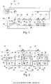
- FIG. 1represents schematically a first example of a medical system comprising a medical device.
- FIG. 2represents schematically a detail of the electrical circuit of the stent in FIG. 1 .
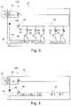
- FIG. 3represents schematically a second example of a medical system comprising a medical device.
- FIG. 4represents schematically a third example of a medical system comprising a medical device.
- FIG. 5shows schematically a detail of the medical device in FIG. 4 .
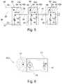
- FIG. 6represents schematically a fourth example of a medical system comprising a medical device.
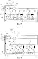
- FIGS. 7 and 8are schematic representations of alternative embodiments of the electrical circuits in FIGS. 1 and 3 .
- FIGS. 9 and 10illustrate schematically an alternative embodiment of the electrical circuit in FIGS. 4 and 5 .
- FIGS. 11 and 12illustrate two examples of electrical circuits having a plurality of measurement lines.
- FIG. 13represents schematically in perspective a stent provided with sensors.
- FIG. 14is a flow chart of a method for querying a medical device.
- FIG. 15represents schematically a medical device identifier comparator.
- FIG. 1illustrates schematically a medical system 10 comprising an implantable medical device 12 and a unit 14 , herein single, for querying the medical device 12 and receiving information from said medical device 12 .
- units for querying and receiving informationmay, alternatively, be separate.
- the medical device 10may further comprise a unit for processing the information received by the receiving unit, for example a computer.
- the implantable medical device 12includes a variable impedance 15 .
- the value of this variable impedance 15is controlled by a control unit not shown, according to the impedance in a measurement circuit 16 , connecting particularly the various sensors 22 of the implantable medical device.
- the implantable medical device 12further includes an electrical power source, herein a source of electric current formed by the body 18 of the implantable medical device 12 . Indeed, under the effect of an electromagnetic field emitted by the querying unit 14 , the body 18 of the implantable medical device 12 induces a current.
- an antenna or armature separate and electrically insulated from the body 18 of the implantable medical device 12may also be provided, particularly in the case wherein the implantable medical device 12 is not suitable, completely or partially, for having an armature function.
- an electrical power source for the measurement circuitmay include a current-conducting surface of the implantable medical device, suitable for inducing an electric current under the effect of an electromagnetic field.
- An electric battery or cellmay also be provided as an electrical power source for the implantable medical device 12 .
- the body 18 of the implantable medical device 12serves herein also as an emitting antenna, to emit an electromagnetic field outside the body wherein the implantable medical device is implanted.
- the intensity of this fieldis directly dependent on the variable impedance 15 , according to the impedance in the measurement circuit 16 .
- the intensity or a standard of the electromagnetic field emitted by the body 18 of the implantable medical device 12is dependent on the impedance of the measurement circuit 16 .
- the implantable medical device 12may include an antenna separate from the body of the implantable medical device or the antenna may be formed by a part at least of the implantable medical device.
- the implantable medical device 12is for example a stent.
- the stentis a tubular metal device, preferably meshed, inserted into a natural human (or animal) cavity to keep it open, as described above in the introduction.
- the stentmay for example be made of a metal alloy or polymer material, but other materials may also be envisaged.
- the implantable medical device 12is provided with variable-impedance sensors 22 according to the physical quantity detected thereby.
- the term physical quantitydenotes herein any property of natural science which may be quantified by measurement or computation, and the different possible values whereof are expressed using any real number or a complex number.
- a physical quantityincludes therefore, for example, a length, an electric current, a voltage, an impedance, a concentration of a chemical element or even the presence and/or concentration of a biological or biochemical element.
- the sensors 22are distributed on the surface of the implantable medical device.
- the sensors 22may particularly be distributed:
- the sensorsmay be coated with an active agent, for example to limit hyperplasia of the tissues in contact with the implantable medical device, particularly when they are positioned on the abluminal surface of a stent or more generally on the outer surface of an implantable medical device intended to be in contact with the wall of the cavity wherein the medical device is implantable.
- an active agentfor example to limit hyperplasia of the tissues in contact with the implantable medical device, particularly when they are positioned on the abluminal surface of a stent or more generally on the outer surface of an implantable medical device intended to be in contact with the wall of the cavity wherein the medical device is implantable.
- a single sensorparticularly a pressure sensor, on the abluminal surface of a stent, or more generally on the outer surface of an implantable medical device already makes it possible to obtain information relating to the poor positioning of the stent or implantable medical device in the cavity. If the pressure measured is low (i.e. less than a threshold pressure), it is likely that the sensor is not in contact with a wall of the cavity, but rather with blood, for example. In the case where two sensors or more are arranged on the abluminal or outer surface, the information may be obtained with more precision by comparing the values measured by the sensors with one another.
- the sensorsare arranged at the locations of the implantable medical device, particularly a stent, subject to the least deformations during the fitting of the implantable medical device, in order to avoid damaging the sensors.
- FIG. 13shows a stent 12 with sensors 22 a fixed to the vertices of the meshes 120 of the stent 12 and sensors 22 c fixed to the mid-point of the sides of the meshes of the stent, it is preferred that all the stents 22 c be fixed to the centre of sides of the meshes 120 of the stent 12 .
- the sensors 22 a , 22 cmay be arranged on the inner face or on the outer face of the stent 12 .
- a pressure sensorin the vicinity of each end of the stent 12 , on the inner face of the stent. As such, a difference in pressure between the values measured by these two sensors may be determined which makes it possible to identify the appearance of a blockage inside the stent.
- Each of the sensorsmay particularly be chosen from:
- the sensors 22are variable-impedance sensors, i.e. sensors wherein the impedance varies according to the amplitude or intensity of the physical quantity detected. Hence, in the event of variation of the amplitude of the physical quantity detected by a sensors of the implantable medical device 12 , the impedance of this sensor varies in the measurement circuit 16 , such that, in the absence of any other variation in the measurement circuit 16 , the impedance of the measurement circuit 16 also varies.
- each sensor 22is associated with a switch 24 suitable for disconnecting from the circuit, in this instance short-circuiting, the sensor 22 with which it is associated.
- thisis carried out by mounting the switch 24 in derivation (or in parallel) with the sensor 22 with which it is associated.
- the sensors 22are herein mounted in series in the measurement circuit 16 .
- each switchis herein embodied by a transistor 24 , in this instance a silicon MOS-FET transistor, more specifically a depletion-mode, P-channel MOS-FET (or p-MOS) transistor.
- each switch or certain switchesmay be embodied by another type of transistor, particularly by a FET transistor, an enhancement-mode MOS-FET transistor, particularly an enhancement-mode N-channel MOS-FET transistor, by a MEMS (standing for “Micromechanical system”), or by a mechanical switch.
- FIG. 1further illustrates a system 26 for controlling the switches 24 , suitable for successively controlling the opening or closing of the switches 24 according to determined configurations.
- the control system 26includes control modules 28 arranged in series with one another, each control module 28 being suitable for controlling the opening or closing of the switch 24 with which it is associated.
- control system 26is configured to normally keep the switches 24 closed and to open same successively and then to close them again such that, at each time, a single switch 24 is open.
- each control module 28is formed herein of a logic circuit, embodied by means of transistors 30 , 32 , 34 , 36 , 38 , a resistor 40 and a capacitor 42 .
- the resistor 40 and the capacitor 42introduce a charging time of the capacitor 42 and a discharging time of said capacitor 42 in the logic circuit.
- the control module 28controls the opening of the associated switch 24 .
- the switch 24is kept closed for the rest of the time, thereby short-circuiting the associated sensor 22 .
- each control module 28is embodied by means of three P-channel transistors 32 , 34 , 38 and two N-channel transistors 30 , 36 , as follows (only the connections hereinafter are made);
- the PMOS type transistor 32When the voltage applied at the input of the first inverter is close to zero, therefore less than the threshold voltage of the transistors 30 and 32 , the PMOS type transistor 32 is switched to the ON-state, charging the capacitor 42 . At the end of the charging thereof, the voltage at the input of the second inverter is greater than the threshold voltage of the transistors 36 and 38 , rendering the NMOS type transistor 36 ON. A voltage close to zero is transmitted at the output of the second inverter connected to the gate of the PMOS type transistor 34 . The latter is then switched to the ON-state, transmitting a voltage close to zero to the gate of the PMOS type switch 24 , which triggers the closing thereof. While a voltage close to zero is applied to the input of the first inverter, the switch 24 is kept closed.
- the NMOS type transistor 30When a voltage greater than the threshold voltage of the transistors 30 and 32 is applied at the input of the first inverter, the NMOS type transistor 30 is switched to the ON-state, transmitting to the output thereof the ground potential, which triggers the discharging of the capacitor 42 .
- the voltage at the input of the second inverterdecreases until it becomes less than the threshold voltage of the transistors 36 and 38 , inhibiting the transistor 36 and activating the transistor 38 .
- the latterthereby transmits to the output of the second inverter a potential greater than the threshold voltage of the transistor 34 , triggering the inhibition thereof. Consequently, the switch 24 opens.
- the openingis induced of the switch 24 which is connected thereto, followed by the successive opening of the switches 24 connected to the subsequent control modules 28 .
- the trailing edge of this pulseinduces the closing of the switch of the first module after a time equal to ⁇ .
- the voltage pulseis propagated from one input 46 to another, such that the trailing edge of this pulse at the input of a module n corresponds to the leading edge of the pulse at the input of the module n+1. As such, in this instance, during the propagation of the pulse, all the switches are closed except one.
- the voltage at the terminals of the measurement circuit 16which is equal to the sum of the voltages at the terminals of each of the sensors mounted in series in the measurement circuit, exhibits successive peaks which are representative of the voltage at the terminals of each of the sensors.
- each representative of the voltage at the terminals of a sensor 22corresponds an intensity of the electromagnetic fields emitted by the body 18 of the implantable medical device 12 having an emitting antenna function.
- FIG. 1the presence of a rectifier 56 as well as of an alternating current generator 58 in the implantable medical device 12 is observed. They make it possible respectively to supply the control circuit 26 with direct current and the measurement circuit 16 with a current having a frequency distinct from, particularly less than, the frequency of the induced current in the antenna 18 . This may be useful as the frequency of the induced current is dependent on the electromagnetic field emitted by the unit 14 said frequency being preferably chosen such that the electromagnetic wave is absorbed to a low degree by the tissues traversed. The use of such a frequency in the measurement circuit could impede the precision of the measurements made.
- the measurement circuit 16is moreover completed in FIG. 1 , by a combination of sets of an impedance 60 , that is fixed and known, and a switch 24 , controlled by a control module 28 , as is the case for the switches 24 associated with the sensors 22 .
- This combination of known impedancesmakes it possible to identify the implantable medical device queried, for example by associating a combination of impedances 60 that are unique and known to each implantable medical device 12 . This particularly useful in the case where a plurality of such implantable medical devices have been implanted in the body of the same patient. Some electromagnetic field peaks measured are then used to identify the implantable medical device 12 , the other peaks to determine the values measured by each of the sensors of the implantable medical device 12 identified.
- the first electromagnetic field peaks measuredmay be used for identifying the implantable medical device 12 and the subsequent peaks for determining the values measured by each of the sensors of the implantable medical device 12 identified.
- these impedancesbeing known, they are also suitable for calibrating the medical system 10 . In other words, these known impedances make it possible to quantify more accurately the values measured by the different sensors of the different implantable medical devices.
- the medical devicemay include a comparator 94 for comparing an identifier ID 1 emitted by the querying unit 14 , with a binary code ID 2 associated with the combination of impedances 60 present on the electrical circuit, this binary code being derived for example from the output of the analogue/digital converter 80 , or an identifier saved in a memory in the stent.
- the medical devicemay then be configured to only respond to the query by the querying unit if the comparison is positive.
- the identificationmay be carried out iteratively, the querying unit merely emitting one identification value at a time, each stent wherein the value corresponding of the identifier not corresponding being disabled—i.e., herein, not electrically powered—for a time suitable for identifying the only stent corresponding to the unique identifier and carrying out the measurements using different sensors in this medical device.
- FIG. 3represents a second example of a medical system 100 .
- This medical systemis substantially identical to that described above.
- the known impedances 60 and the sensorsare mounted in series with the switch 24 which is associated therewith, the sets formed of an impedance 60 or a sensor 22 and a switch 24 being mounted in parallel (or in derivation) with respect to one another.
- the control modules 28being identical to those described above, the electromagnetic field emitted following the creation of an induced current, corresponds to the sum of all the impedances 60 and of all the sensors 22 , minus one, each of the impedances 60 and the sensors 22 being disconnected from the circuit, in this instance disconnected, successively.
- control module 28having a different operation, which controls the closing of the switch 24 during a time interval only, the switch 24 being open the rest of the time.
- Such an operationmay also be obtained by retaining the control module 28 as described above and by replacing the depletion-mode MOS-FET transistors used as switches 24 by enhancement-mode MOS-FET transistors.
- FIGS. 4 and 5illustrate a further example of a medical system 200 .
- the control of the switch 24 for disconnecting from the circuit the sensor 22 or a known impedance 60is implanted directly in a module 62 also comprising the known impedance 60 or the sensor 22 , and the switch 24 , herein embodied by a transistor.
- a resistor 40 and a capacitor 42are used to control the switch 24 such that it disconnects from the circuit the impedance 60 or the sensor 22 except during a charging time interval of the capacitor 42 .
- Charging the capacitor 42activates the transistor 66 of the next module, inducing the charging of the corresponding capacitor 42 . Once charged, the capacitor 42 inhibits the associated transistor 24 , triggering the disconnection from the circuit of the impedance 60 or the sensor 22 which is connected thereto.
- each module 62is embodied as following:
- each sensor 22 and impedance 66is successively connected to the antenna 18 in order to be powered, the other sensors 22 and impedances 66 being for their part disconnected.
- FIG. 6represents a fourth example of an embodiment of a medical system 300 .
- This medical system 300is distinguished from the preceding example 200 , in that the measurement circuit 16 is directly connected to the antenna 18 for the emission of an electromagnetic field, without the intermediary of a separate variable impedance (the measurement circuit 16 itself having a variable impedance) and of a unit for controlling this variable impedance according to the impedance of the measurement circuit 16 .
- the electrical circuit on the medical device 12is then particularly simplified.
- the measurement circuit 16is connected directly to the antenna, the implantable medical device also comprising a control circuit associated with this measurement circuit and as described for example with regard to FIGS. 2 and 3 .
- each modulemay particularly by embodied in the following form.
- Two measurement electrodesfor example of 60 ⁇ 60 ⁇ m 2 , made of an electrically conductive material, for example of polymer material or of metal alloy, preferably biocompatible, are deposited on an electrically insulating, biocompatible polymeric substrate (for example parylene).
- the electrical components of the control system and the switchare implanted in the polymeric substrate.
- the medical systems described aboveare suitable for carrying out a querying method 500 of the implantable medical device 12 , as shown by the flow chart in FIG. 14 .
- This method 500includes a first step 502 consisting of powering the measurement circuit 16 .
- this power supplyis carried out by an induced current in an antenna or in the body of the implantable medical device 12 when the latter is configured to generate an induced current. This makes it possible to power the measurement circuit 16 only when a measurement is made.
- the method 500is continued by a step 504 consisting of activating the system for controlling the implantable medical device so that it successively controls the opening of the closing of each of the switches of the implantable medical device, according to determined configurations. It should be noted herein that within the scope of the examples described with regard to the figures, this activation is carried out simultaneously with the power supply of the measurement circuit 16 , by induction, in response to the emission of an electromagnetic field by the querying device.
- the method 500then includes a step 506 for identifying the queried medical device. This step may, alternatively, be carried out before electrically powering the measurement circuit.
- the identificationmay be carried out either in the medical device per se, when the latter is provided with a comparator to compare an identification signal emitted by the querying unit with a unique identifier of the medical device.
- this identifiermay take the form of a combination of known impedances in the medical device and/or in each measurement line of the medical device.
- the identificationmay be carried out iteratively, the querying unit merely emitting one digit of the identifier at a time, each of the medical devices wherein the identifier does not correspond to this digit being temporarily deactivated (i.e., in the example studied, not electrically powered).
- the identificationis carried out in the processing unit, the signals emitted by the antenna 18 being interpreted by the processing unit to determine the combination of the impedances of the medical device and/or of the measurement line queried.
- a processing unitmay be used to determine the value measured by each sensor and the implantable medical device that responded to the query, particularly if the controlled configurations of the measurement circuit are more complex.
- the processing unitmay particularly be suitable for conducting Fourier analyses of the measured signals of electromagnetic fields emitted by the antenna of the implantable medical device, comparing the signals received (optionally processed) to previously measured signals and inferring therefrom the values measured by the various sensors of the implantable medical device, one location being suitable for being determined for each of the values measured.
- the medical deviceis temporarily deactivated, in the step 508 .
- the method 500is continued then by a step 510 consisting of measuring the electromagnetic field emitted by the antenna of the implantable medical device.
- This measurementis made over a relatively long time so that the control system will have been able to control a relatively large number of different configurations of the measurement circuit so that the measurement makes it possible to determine the value measured by each of the sensors 22 of the implantable medical device 12 .
- the antenna 14preferably emits a constant electromagnetic field to maintain the power supply of the measurement circuit 16 and the activation of the control system 26 .
- each configurationcorresponds to the scenario where all the sensors or impedances of the measurement circuit are disconnected from the circuit, except one.
- the electromagnetic field measuredit is possible to determine first of all the implantable medical device that responded to the query.
- the first peaks measured in the electromagnetic field emitted by the antennacorrespond to fixed impedances, the combination whereof makes it possible to identify the implantable medical device.
- These magnetic fields measuredmay also be suitable for calibrating the system since the magnetic fields measured correspond to known impedances of the measurement circuit.
- the subsequent magnetic fieldsmake it possible to determine the values measured by each of the sensors distributed on the implantable medical device.
- the corresponding magnetic fields emittedmay be used to calibrate the following and/or preceding emitted signal, which originates from a measurement by a sensor 22 .
- the electrical power supply of the electrical circuitis switched off and the electrical circuit of the medical device 12 is deactivated.
- variable-impedance sensormay be used with any type of variable-impedance sensor according to the physical quantity detected thereby. It should also be noted that the sensors distributed on the implantable medical device may be of different types, i.e. they may detect different physical quantities.
- the method described abovemay particularly be used to determine whether the implantable medical device is suitably implanted (i.e. positioned) in the natural cavity that it is supposed to keep open, in particular, if it is indeed in contact with the wall of the cavity. Indeed, the effect of a stent, for example but this is true for most implantable medical devices, is markedly reduced if the latter is not bearing on the wall of the cavity (particularly of the vein or the artery) wherein it is inserted.
- the method described abovemakes it possible to determine whether each of these sensors is in contact with the wall, since it makes it possible to determine the pressure measured by each of the sensors.
- this function for determining the suitable position of the stentmay be combined, that is to say that sensors, for example of pressure, may be arranged on the abluminal surface of the stent and sensors, optionally of another physical quantity, may be arranged on the luminal surface of the stent.
- sensors of the same physical quantityare distributed on the abluminal surface and on the luminal surface, substantially at the same position on the stent or implantable medical device.
- sensors of the same physical quantityare arranged at the same point of the stent, on either side of the stent body.
- the comparison of the values measured by each of these stent pairsalso makes it possible to obtain indications of an incorrect position of the stent in the cavity.
- the sensor on the abluminal surfacewhich should therefore be in contact with a wall, measures a substantially identical value to the sensor on the luminal surface, which is in contact with the blood, it is likely that the sensor on the abluminal surface is in fact in contact with blood also, not with a wall. It is therefore likely that the stent is poorly positioned in the cavity.
- a sensor arranged on the luminal or abluminal surface of the stent or, more generally, on a surface of an implantable medical device, particularly on a surface of the implantable medical device in contact with a wall of the cavity wherein the medical device is implanted or on a surface of the implantable medical device intended to be in contact with the bloodis optionally coated with endothelial or smooth muscle tissue.
- EISElectrical Impedance Spectroscopy
- the electrical circuit 10 A in FIG. 7is an alternative embodiment of the circuit in FIG. 1 .
- the electrical circuit 10 Afirstly includes an analogue/digital converter 80 situated between the electrical measurement circuit 16 and the variable impedance 15 connected to the antenna 18 in the emitting circuit.
- This analogue/digital converter 80which may also be used in the electrical circuit 10 in FIG. 1 makes it possible to increase the range of signals which may be emitted by the antenna 18 .
- This converter 80also makes it possible to enhance the signal-to-noise ratio of the measurements made.
- the electrical circuit 10 Ais distinguished from that in FIG. 1 by the presence of an element 60 A of fixed and known impedance, for example a resistor, between the sensors 22 .
- the element 60 Ais associated with a switch 24 controlled by a control module 28 in a module 62 A.
- the impedance of this element 60 Ais preferably chosen such that the sensors 22 cannot attain this impedance value.
- the impedance of the element 60 Ais less than 90% of the minimum impedance suitable for being attained by sensor 22 and/or greater than 110% of the maximum impedance suitable for being attained by a sensor 22 .
- a transition signalAs such, between two emitted signals relative to a measurement by a sensor 22 , a transition signal, easily identifiable, is emitted. It is easier, as such, to distinguish between two successive measurements, separated by a signal of expected form. Moreover, the presence of this element 60 A between the sensors 22 may be suitable for calibrating the following and/or preceding sensor 22 . The measurement is therefore more precise. Obviously, further configurations may be envisaged. In particular, it is possible to envisage an element 60 A at the start of a line only, all the n sensors 22 , n being a natural integer different to zero, or even an irregular distribution of the elements 60 A on the measurement line.
- FIG. 8represents an alternative embodiment 100 A of the electrical circuit 100 in FIG. 3 , with an analogue/digital converter 80 and elements 60 A of known and fixed impedance, such as the electrical circuit 10 A.
- the advantages of these modificationsare the same as within the scope of the electrical circuit 10 A in FIG. 7 .
- FIG. 11an electrical diagram of an alternative electrical circuit 10 B of the electrical circuit 10 in FIG. 1 has been represented.
- This electrical diagram 10 Bis distinguished from the electrical circuit 10 in FIG. 1 in that it includes a plurality of measurement lines 90 , mounted in parallel, where the electrical circuit 10 in FIG. 1 merely includes a single line.
- the measurement lines 90are identical to the single line represented in FIG. 1 .
- the measurement circuit 16includes however line selectors 92 , to carry out the measurement in each of the lines independently from the other lines 90 , particularly each line in succession from one another.
- the line selectors 92may adopt a substantially identical form to the control modules 28 , thereby supplying each line 90 with current, successively.
- an analogue/digital converter 80is also provided between the parallel branches formed by the measurement lines 90 and the variable impedance 15 .
- the electrical circuit 10 C illustrated in FIG. 12is similar to the electrical circuit 10 B in FIG. 11 . It is essentially distinguished by the presence of an analogue/digital converter 80 on each of the measurement lines 90 in parallel.
- the electrical circuit 10 B, 10 Cincludes a plurality of measurement lines
- the measurement linesextend on the medical device 12 , particularly on the stent 12 in imbricated coaxial helices.
- the measurement linesextends in parallel along helices wound around one another. Indeed, this makes it possible to minimise the distance between sensors of different lines.
- Thisis particularly advantageous because if a sensor 22 of a line 90 , or even the entire line 90 is defective, the missing value(s) may be better approximated by the values measured with the other measurement line(s), of which one or a plurality of sensors are situated in the vicinity.
- the device 12thereby gains in robustness, which is particularly advantageous when it is implanted in a patient's body.
- the electrical circuits describedare suitable for determining for each sensor of the electrical circuits, the value measured thereby.
- Representing the pressures measured by pressure sensors arranged on the outer surface of the medical device, particularly of the stent,can enable the practitioner to determine whether this medical device is correctly implanted or not: a measured pressure that is too low, for example, may indicate that the stent is not in contact with the wall of the cavity receiving same.
- the processing unit of the medical system described abovecomprising for example an electronic control unit and a screen, or a computer, may be suitable for determining a real-time model, for example a 3D model, based on the values measured and displaying the model on the screen.
- the values between the measurement pointsmay, in this case, be approximated, particularly by convolution according to the distance to the closest measurement points.
- Various visual and/or acoustic signalsmay be emitted by the processing unit, in the scenario where at least one measured value does not meet expectations.
- the visual signalsmay particularly be suitable for identifying on the model shown, the sensors 22 for which the measured values are not conforming.
- the processing unitmay process the digital values measured, compare them to expected value ranges and display as an output in a different manner, the points where the measurement is within the ranges and the points where the measurement is not within the ranges, for example by using different display colours.
- the visual signalscomplete the display of the model described above.
- the implantable medical devicemay be chosen from the group comprising:
- the medical devicemay not be implantable. It can then, in particular, be applied on a part of the human body.
- the medical devicemay in this case take the form of a dressing, bandage or strip to be applied onto a patient's skin.
- the medical devicemay also take the form of a contact lens to be placed on a patient's cornea.
- the medical devicemay be neither implantable in the human body, not applicable thereon.
Landscapes
- Health & Medical Sciences (AREA)
- Life Sciences & Earth Sciences (AREA)
- Engineering & Computer Science (AREA)
- Biomedical Technology (AREA)
- General Health & Medical Sciences (AREA)
- Heart & Thoracic Surgery (AREA)
- Veterinary Medicine (AREA)
- Public Health (AREA)
- Animal Behavior & Ethology (AREA)
- Medical Informatics (AREA)
- Molecular Biology (AREA)
- Biophysics (AREA)
- Surgery (AREA)
- Physics & Mathematics (AREA)
- Pathology (AREA)
- Vascular Medicine (AREA)
- Cardiology (AREA)
- Physiology (AREA)
- Transplantation (AREA)
- Computer Networks & Wireless Communication (AREA)
- Oral & Maxillofacial Surgery (AREA)
- Computing Systems (AREA)
- Signal Processing (AREA)
- Human Computer Interaction (AREA)
- Measurement And Recording Of Electrical Phenomena And Electrical Characteristics Of The Living Body (AREA)
- Measuring And Recording Apparatus For Diagnosis (AREA)
- Prostheses (AREA)
Abstract
Description
- the medical device is implantable in the human body or can be applied on the human body;
- each switch is formed by one or more transistors, particularly one or more field-effect transistors FET, more particularly one or more metal-oxide-semiconductor field-effect transistors MOS-FET, enhancement or depletion mode, N-channel or P-channel type, one or more MEMS, or one or more mechanical switches;
- the system for controlling the switches includes a control circuit, powered by the electrical power source, and configured, preferably, to control successively the opening or closing of the various switches, one after the other;
- the control system includes components implanted directly in the measurement circuit, preferably to control successively the opening or closing of the various switches, one after the other;
- the control system includes modules having the same structure, arranged in series with respect to one another, each controlling an associated switch;
- the input of the first module controls successively the opening or closing of the various switches, one after the other; in other words, a change of status of this input triggers, after some time, a change of status at the output of the module corresponding to the input of the next module;
- each module includes a series RC circuit the charging or discharging whereof triggers the closing or opening of the associated switch;
- charging or discharging of a series RC circuit of a module induces the charging or discharging of the series RC circuit of the next module;
- each module includes:
- a first transistor the source whereof is connected to the input of the module, the gate to the output thereof and the drain to the gate of the associated switch,
- a first inverter the input whereof is connected to that of the module and the output to a first terminal of the resistor of the series RC circuit, the second terminal of the resistor being connected to a first terminal of the capacitor, the second terminal thereof being connected to the ground,
- a second inverter the input whereof is connected to the second terminal of the resistor and the output to that of the of the module, said output forming the input of the next module.
- each module includes:
- a first transistor the gate whereof is connected to the input of the module and the drain to the positive power supply terminal;
- a second transistor the source whereof is connected to that of the first transistor, the gate to the output of the module and the drain to a first terminal of the variable-impedance sensor the second terminal whereof is connected to the ground,
- a diode the anode whereof is connected to the source of the first transistor and the cathode to a first terminal of the resistor of the series RC circuit, the second terminal thereof being connected to the output of the module, the capacitor of the series RC circuit being connected between the output of the module and the ground.
- each set of a switch and a sensor is mounted in series and the sets of a switch and a sensor are mounted in parallel with respect to one another;
- each set of a switch and a sensor is mounted in parallel and the sets of a switch and a sensor are mounted in series with respect to one another; the electrical power source includes a current-conducting surface of the medical device, suitable for inducing an electrical current under the effect of an electromagnetic field;
- at least one of the sensors is arranged on a surface of the medical device, intended to be in contact with a part of the body whereon the device is applied or wherein the device is implantable;
- the antenna is formed by a part at least of the medical device;
- the measurement circuit includes a plurality of fixed impedances, each associated with a switch the opening and closing whereof are controlled by the control system; the medical device is implantable in the human body and is chosen from the group comprising:
- a vascular support or stent, at least one sensor being preferably arranged on an abluminal surface of the vascular stent,
- a heart valve,
- a cardiac stimulator,
- a cochlear implant,
- a throat implant,
- an orthopaedic implant,
- a brain implant,
- a retinal implant,
- a catheter, or
- a cellular tissue;
- each sensor is chosen from:
- a shear sensor,
- a pressure sensor,
- an impedance sensor,
- a heat dissipation sensor,
- a stress gauge, and
- a flow sensor, particularly of the hot-wire type;
- the implantable medical device is a vascular stent with at least one impedance sensor arranged on an abluminal surface of the vascular stent;
- the medical device forms a through conduit, the medical device including two pressure sensors arranged at each of the ends of the through conduit, in the through conduit;
- the medical device comprises between two sensors each associated with a switch, an element of fixed and known impedance being preferably provided between each of the sets of a sensor associated with a switch;
- the medical device is a meshed vascular stent, at least one sensor, preferably all the sensors, being arranged at the mid-point of one side of a mesh of the vascular stent;
- the medical device comprises at least one analogue/digital converter, the output signal whereof controls the emitting antenna, optionally indirectly, particularly via a variable resistor; and
- the medical device comprises a plurality of measurement lines, the measurement lines extending on the medical device, particularly on the vascular stent, along coaxial helices.
- powering the measurement circuit of the medical device,
- activating the control system so that it successively controls the opening or closing of each of the switches, according to determined configurations, and
- measuring the electromagnetic field emitted by the antenna of the medical device.
- only on the “abluminal” surface of the body of the stent, i.e. the surface opposite the lumen through the stent, intended to be in contact with the wall of the cavity to be kept open but not on the luminal surface; or
- only on the luminal surface but not on the abluminal surface; or
- both on the luminal and abluminal surfaces; and
- on the surfaces connecting the luminal and abluminal surfaces.
- a shear sensor,
- a pressure sensor,
- an impedance sensor,
- a heat dissipation sensor,
- a stress gauge, and
- a flow sensor of the “hot wire sensor” type.
- first and
second branches measurement circuit 16 are connected in parallel, thefirst branch 44 being the positive power supply terminal and thesecond branch 46 being the input of themeasurement circuit 16 which is powered by a start circuit, not shown in the figures, configured to generate a crenelated voltage pulse during a certain time interval; - the gate of the
first transistor 30 and the gate of thesecond transistor 32 are connected together, as well as to the source of thethird transistor 34 and to thesecond branch 46 of the precedingcontrol module 28, the twotransistors - the gate of the
fourth transistor 36 and the gate of thefifth transistor 38 are connected together as well as to a terminal of theresistor 40 and to a terminal of thecapacitor 42, the twotransistors - the source of the
first transistor 30, the source of thefourth transistor 36 and a terminal of thecapacitor 42 are connected to theground 48; - the other terminal of the
resistor 40, which is not connected to thecapacitor 42, is connected to the drain of thefirst transistor 30 and to the drain of thesecond transistor 32; - the drain of the
fourth transistor 36 and the drain of thefifth transistor 38 are connected together to thesecond branch 46 of thenext control module 28, as well as the gate of thethird transistor 34; - the source of the
second transistor 32 and the source of thefifth transistor 38 are connected together to thefirst branch 44 of the precedingcontrol module 28; - the drain of the
third transistor 34 is connected to the gate of thetransistor 24 having a switch function to short-circuit thesensor 22.
- first and
- the first and
second branches - a terminal of the
sensor 22 or of theimpedance 60 is connected to theground 48; - the other terminal of the
sensor 22 or of theimpedance 60 is connected to the drain of thetransistor 24; - the gate of the
second transistors 66 is connected to thesecond branch 46 of the precedingmodule 62; - the drain of the
second transistor 66 is connected to thefirst branch 44 of the preceding andnext modules 62; - the source of the
second transistor 66 is connected to the source of thetransistor 24 and to adiode 64; - the other terminal of the
diode 64, which is not connected to thetransistors impedance 40; - the other terminal of the
impedance 40, which is not connected to thediode 64, is connected to the gate of thetransistor 24, to a terminal of acapacitor 42, connected by the other terminal thereof to theground 48, and to thesecond branch 46 of thenext module 62.
- the first and
- a heart valve,
- a cardiac stimulator,
- a cochlear implant,
- a throat implant,
- an orthopaedic implant,
- a brain implant,
- a retinal implant,
- a catheter, or
- a cellular tissue (“tissue-engineered construct”).
Claims (26)
Applications Claiming Priority (3)
| Application Number | Priority Date | Filing Date | Title |
|---|---|---|---|
| FR1653032 | 2016-04-06 | ||
| FR1653032AFR3049843A1 (en) | 2016-04-06 | 2016-04-06 | MEDICAL DEVICE PROVIDED WITH SENSORS |
| PCT/EP2017/058169WO2017174688A1 (en) | 2016-04-06 | 2017-04-05 | Medical device provided with sensors |
Related Parent Applications (1)
| Application Number | Title | Priority Date | Filing Date |
|---|---|---|---|
| PCT/EP2017/058169A-371-Of-InternationalWO2017174688A1 (en) | 2016-04-06 | 2017-04-05 | Medical device provided with sensors |
Related Child Applications (1)
| Application Number | Title | Priority Date | Filing Date |
|---|---|---|---|
| US17/990,406ContinuationUS20230181047A1 (en) | 2016-04-06 | 2022-11-18 | Medical device provided with sensors |
Publications (2)
| Publication Number | Publication Date |
|---|---|
| US20190159684A1 US20190159684A1 (en) | 2019-05-30 |
| US11510577B2true US11510577B2 (en) | 2022-11-29 |
Family
ID=56802542
Family Applications (2)
| Application Number | Title | Priority Date | Filing Date |
|---|---|---|---|
| US16/091,766Active2040-03-26US11510577B2 (en) | 2016-04-06 | 2017-04-05 | Medical device provided with sensors |
| US17/990,406PendingUS20230181047A1 (en) | 2016-04-06 | 2022-11-18 | Medical device provided with sensors |
Family Applications After (1)
| Application Number | Title | Priority Date | Filing Date |
|---|---|---|---|
| US17/990,406PendingUS20230181047A1 (en) | 2016-04-06 | 2022-11-18 | Medical device provided with sensors |
Country Status (8)
| Country | Link |
|---|---|
| US (2) | US11510577B2 (en) |
| EP (1) | EP3439540B1 (en) |
| JP (1) | JP7115747B2 (en) |
| CN (1) | CN109310327B (en) |
| AU (1) | AU2017247677B2 (en) |
| ES (1) | ES2949711T3 (en) |
| FR (1) | FR3049843A1 (en) |
| WO (1) | WO2017174688A1 (en) |
Cited By (2)
| Publication number | Priority date | Publication date | Assignee | Title |
|---|---|---|---|---|
| US11730925B2 (en) | 2021-06-28 | 2023-08-22 | Inquis Medical, Inc. | Apparatuses and methods for tracking obstructive material within a suction catheter |
| US12339717B2 (en)* | 2018-07-31 | 2025-06-24 | Taiwan Semiconductor Manufacturing Company, Ltd. | Discrete time loop based thermal control |
Families Citing this family (6)
| Publication number | Priority date | Publication date | Assignee | Title |
|---|---|---|---|---|
| US10667931B2 (en)* | 2014-07-20 | 2020-06-02 | Restore Medical Ltd. | Pulmonary artery implant apparatus and methods of use thereof |
| FR3026631B1 (en) | 2014-10-03 | 2016-12-09 | Ecole Polytech | IMPLANTABLE MEDICAL DEVICE WITH SENSORS |
| CN110244033B (en)* | 2019-06-06 | 2022-07-26 | 太原理工大学 | Portable urine detection device and detection method thereof |
| WO2020257759A1 (en)* | 2019-06-21 | 2020-12-24 | The Johns Hopkins University | System for monitoring of the functional status of implanted heart valves |
| WO2022123565A1 (en) | 2020-12-09 | 2022-06-16 | Ceretrive Ltd. | Retrieval system and method |
| DE102023132477A1 (en)* | 2023-11-21 | 2025-05-22 | Jochen Kuhn | Sensor circuit |
Citations (96)
| Publication number | Priority date | Publication date | Assignee | Title |
|---|---|---|---|---|
| US5800350A (en) | 1993-11-01 | 1998-09-01 | Polartechnics, Limited | Apparatus for tissue type recognition |
| US5938624A (en) | 1997-09-10 | 1999-08-17 | Radi Medical Systems Ab | Male connector with a continous surface for a guide wire and method therefor |
| WO1999042176A1 (en) | 1998-02-23 | 1999-08-26 | Vascusense, Inc. | Endoluminal implant with therapeutic and diagnostic capability |
| US6063028A (en) | 1997-03-20 | 2000-05-16 | Luciano; Joanne Sylvia | Automated treatment selection method |
| US6090052A (en) | 1997-03-25 | 2000-07-18 | Radi Medical Systems Ab | Guide wire having a male connector |
| US6106486A (en) | 1997-12-22 | 2000-08-22 | Radi Medical Systems Ab | Guide wire |
| US6112598A (en) | 1995-06-22 | 2000-09-05 | Radi Medical Systems Ab | Pressure sensor and guide wire assembly for biological pressure measurements |
| WO2000056210A1 (en) | 1999-03-24 | 2000-09-28 | Noveon Ip Holdings Corp. | Remotely interrogated diagnostic implant device with electrically passive sensor |
| JP2000271101A (en) | 1999-03-26 | 2000-10-03 | Matsushita Electric Ind Co Ltd | Body impedance measuring device |
| US6206835B1 (en) | 1999-03-24 | 2001-03-27 | The B. F. Goodrich Company | Remotely interrogated diagnostic implant device with electrically passive sensor |
| WO2001037726A1 (en) | 1999-11-23 | 2001-05-31 | Noveon Ip Holding Corp. | Remotely interrogated medical implant with sensor |
| CN1329290A (en) | 2000-06-19 | 2002-01-02 | 精工爱普生株式会社 | Oscillating circuit, electronic circuit, semiconductor device, electronic equipment and clock |
| US20020043113A1 (en) | 2000-01-31 | 2002-04-18 | Radi Medical Systems Ab | Triggered flow measurement |
| US20020077627A1 (en) | 2000-07-25 | 2002-06-20 | Johnson Theodore C. | Method for detecting and treating tumors using localized impedance measurement |
| US6428336B1 (en) | 1997-03-25 | 2002-08-06 | Radi Medical Systems Ab | Female connector |
| DE10103503A1 (en) | 2001-01-26 | 2002-08-14 | Fraunhofer Ges Forschung | Endoluminal expandable implant with integrated sensors |
| US6437551B1 (en) | 1999-11-02 | 2002-08-20 | The Regents Of The University Of California | Microfabricated AC impedance sensor |
| US6461301B2 (en) | 2000-03-21 | 2002-10-08 | Radi Medical Systems Ab | Resonance based pressure transducer system |
| US20020177782A1 (en) | 2000-10-16 | 2002-11-28 | Remon Medical Technologies, Ltd. | Barometric pressure correction based on remote sources of information |
| US20030030499A1 (en)* | 2001-08-10 | 2003-02-13 | Congzhong Huang | Trimmable low voltage oscillator |
| WO2003057011A2 (en) | 2002-01-04 | 2003-07-17 | Canswers Llc | Systems and methods for predicting disease behavior |
| US6679269B2 (en) | 1995-07-28 | 2004-01-20 | Scimed Life Systems, Inc. | Systems and methods for conducting electrophysiological testing using high-voltage energy pulses to stun tissue |
| JP2004041724A (en) | 2002-06-17 | 2004-02-12 | Biosense Inc | Apparatus and method for locating tissue within body of subject |
| US20040127960A1 (en) | 2001-01-16 | 2004-07-01 | Cardiac Pacemakers, Inc. | Split-can dipole antenna for an implantable medical device |
| CN1576862A (en) | 2003-07-29 | 2005-02-09 | 阿尔卑斯电气株式会社 | Capacitance detector, method of detecting capacitance, and fingerprint sensor |
| US20050065592A1 (en) | 2003-09-23 | 2005-03-24 | Asher Holzer | System and method of aneurism monitoring and treatment |
| US20060047205A1 (en) | 2002-10-07 | 2006-03-02 | Integrated Sensing Systems, Inc. | Delivery method and system for monitoring cardiovascular pressures |
| CN1788677A (en) | 2005-12-23 | 2006-06-21 | 梁文锋 | Instrument for human body acupoint searching, diagnosis and treatment |
| WO2006070369A2 (en) | 2004-12-30 | 2006-07-06 | Given Imaging Ltd. | Device, system and method for orienting a sensor in-vivo |
| WO2006113747A2 (en) | 2005-04-19 | 2006-10-26 | Prediction Sciences Llc | Diagnostic markers of breast cancer treatment and progression and methods of use thereof |
| US20060254600A1 (en) | 2000-03-27 | 2006-11-16 | Asthmatx, Inc. | Methods for treating airways |
| CN101004424A (en) | 2006-01-20 | 2007-07-25 | 深圳迈瑞生物医疗电子股份有限公司 | Device and method for detecting jam of sample needle of biochemical analyser |
| US20070255145A1 (en) | 2006-04-28 | 2007-11-01 | Radi Medical Systems Ab | Sensor and guide wire assembly |
| US20070255270A1 (en) | 2006-04-27 | 2007-11-01 | Medtronic Vascular, Inc. | Intraluminal guidance system using bioelectric impedance |
| US20080180345A1 (en)* | 2007-01-30 | 2008-07-31 | Larson Dennis E | Variable antenna matching network for an implantable antenna |
| US20080262489A1 (en) | 2007-04-23 | 2008-10-23 | Minnow Medical, Llc | Thrombus removal |
| US20090118808A1 (en) | 2004-09-23 | 2009-05-07 | Medtronic, Inc. | Implantable Medical Lead |
| WO2009103156A1 (en) | 2008-02-20 | 2009-08-27 | Mcmaster University | Expert system for determining patient treatment response |
| WO2009114689A1 (en) | 2008-03-12 | 2009-09-17 | The Trustees Of The University Of Pennsylvania | Flexible and scalable sensor arrays for recording and modulating physiologic activity |
| US20090267588A1 (en)* | 2008-04-23 | 2009-10-29 | Schmitz Michael J | Method and apparatus to dynamically control impedance to maximize power supply |
| WO2009136167A1 (en) | 2008-05-07 | 2009-11-12 | University Of Strathclyde | System for characterising or monitoring implanted devices |
| WO2009136157A2 (en) | 2008-05-07 | 2009-11-12 | University Of Strathclyde | A system and method for cell characterisation |
| US20100191141A1 (en) | 2009-01-27 | 2010-07-29 | Peter Aberg | Method and apparatus for diagnosing a diseased condition in tissue of a subject |
| US7792588B2 (en)* | 2007-01-26 | 2010-09-07 | Medtronic, Inc. | Radio frequency transponder based implantable medical system |
| WO2011022418A2 (en) | 2009-08-17 | 2011-02-24 | The Regents Of The University Of California | Distributed external and internal wireless sensor systems for characterization of surface and subsurface biomedical structure and condition |
| WO2011057024A2 (en) | 2009-11-04 | 2011-05-12 | Proteus Biomedical, Inc. | System for supply chain management |
| US7991484B1 (en)* | 2007-05-15 | 2011-08-02 | Pacesetter, Inc. | Active fixation medical lead and related method and system |
| WO2011121581A1 (en) | 2010-04-02 | 2011-10-06 | Universita' Degli Studi Di Roma "Tor Vergata" | Device implantable in biological ducts |
| US20110251469A1 (en) | 2010-04-09 | 2011-10-13 | The Board Of Trustees Of The University Of Arkansas | Wireless nanotechnology based system for diagnosis of neurological and physiological disorders |
| US20120016206A1 (en) | 2010-07-16 | 2012-01-19 | Navya Network Inc. | Treatment decision engine with applicability measure |
| US20120036689A1 (en) | 2010-08-10 | 2012-02-16 | Sjoesten Thomas | Device for pressing on a double clutch |
| CN102370476A (en) | 2011-09-28 | 2012-03-14 | 上海交通大学 | Cardiovascular blood flow velocity sensor |
| US20120061257A1 (en) | 2010-09-14 | 2012-03-15 | University Of Southern California | Concentric bipolar electrochemical impedance spectroscopy to assess vascular oxidative stress |
| CA2814557A1 (en) | 2010-10-15 | 2012-04-19 | Fraunhofer-Gesellschaft Zur Foerderung Der Angewandten Forschung E.V. | Sensor system for implantation into a body, and method for producing the sensor system |
| US20120172731A1 (en) | 2009-09-15 | 2012-07-05 | St. Jude Medical Systems Ab | Rapid exchange guide unit |
| US8233979B1 (en) | 2007-03-21 | 2012-07-31 | Pacesetter, Inc. | Distributed anode cardiac pacing and sensing |
| US8277386B2 (en) | 2004-09-27 | 2012-10-02 | Volcano Corporation | Combination sensor guidewire and methods of use |
| US20120283714A1 (en)* | 2011-05-02 | 2012-11-08 | Teresa Ann Mihalik | Methods of treatment with compliant elements and wire structures |
| US20120316454A1 (en) | 2011-06-10 | 2012-12-13 | Paul Carter | Electrode impedance spectroscopy |
| US8478378B2 (en) | 2007-09-04 | 2013-07-02 | The Regents Of The University Of California | Devices, systems and methods to detect endothelialization of implantable medical devices |
| US8491567B2 (en) | 2006-03-30 | 2013-07-23 | Volcano Corporation | Method and system for imaging, diagnosing, and/or treating an area of interest in a patient's body |
| US20130274712A1 (en) | 2011-11-02 | 2013-10-17 | Stuart O. Schecter | Haptic system for balloon tipped catheter interventions |
| US20130282084A1 (en) | 2004-09-10 | 2013-10-24 | Vessix Vascular, Inc. | Apparatus and Method for Treatment of In-Stent Restenosis |
| US20140005558A1 (en) | 2012-06-29 | 2014-01-02 | Boston Scientific Scimed, Inc. | Pressure sensing guidewire |
| US20140058275A1 (en) | 2012-08-27 | 2014-02-27 | Boston Scientific Scimed, Inc. | Pressure-sensing medical devices and medical device systems |
| US20140058197A1 (en) | 2008-11-11 | 2014-02-27 | Amr Salahieh | Low Profile Electrode Assembly |
| US20140066791A1 (en) | 2012-08-31 | 2014-03-06 | Volcano Corporation | Mounting Structures for Components of Intravascular Devices |
| US20140066790A1 (en) | 2012-08-31 | 2014-03-06 | Volcano Corporation | Pressure Sensing Intravascular Devices With Reduced Drift and Associated Systems and Methods |
| US20140081244A1 (en) | 2012-09-17 | 2014-03-20 | Boston Scientific Scimed, Inc. | Pressure sensing guidewire |
| US20140180031A1 (en) | 2012-12-21 | 2014-06-26 | Volcano Corporation | Multi-sensor devices |
| US8777898B2 (en) | 2011-01-31 | 2014-07-15 | Boston Scientific Scimed, Inc. | Medical devices having releasable coupling |
| US20140276109A1 (en) | 2013-03-15 | 2014-09-18 | Boston Scientific Scimed, Inc. | Pressure sensing guidewire |
| US20140276223A1 (en) | 2013-03-15 | 2014-09-18 | St. Jude Medical Systems Ab | Sensor guide wire device and system including a sensor guide wire device |
| US8840560B2 (en) | 2006-04-04 | 2014-09-23 | Volcano Corporation | Ultrasound catheter and hand-held device for manipulating a transducer on the catheter's distal end |
| US20140284422A1 (en) | 2013-03-21 | 2014-09-25 | Itzhak Sapir | Hovering Surveillance Air Vehicle |
| US20140343382A1 (en) | 2013-05-17 | 2014-11-20 | Xhale, Inc. | Methods And Systems For Using A Thermistor In Probe Identification Circuits In Or Associated With Pulse Oximeter Sensors |
| US20140343629A1 (en)* | 2013-05-16 | 2014-11-20 | Greatbatch Ltd. | Method and apparatus for displaying a graphical impedance history for output channels of a lead |
| US20150032011A1 (en) | 2013-07-26 | 2015-01-29 | Boston Scientific Scimed, Inc. | Ffr sensor head design that minimizes stress induced pressure offsets |
| US20150051499A1 (en) | 2013-08-14 | 2015-02-19 | Boston Scientific Scimed, Inc. | Medical device systems including an optical fiber with a tapered core |
| US20150123679A1 (en)* | 2012-05-10 | 2015-05-07 | Access Business Group International Llc | System and method for measuring variable impedance elements in a wireless sensor |
| US9048752B2 (en)* | 2012-09-27 | 2015-06-02 | Semiconductor Components Industries, Llc | Off-line power converter and integrated circuit suitable for use in same |
| US20150209526A1 (en) | 2014-01-14 | 2015-07-30 | Volcano Corporation | Devices and methods for forming vascular access |
| US9121806B1 (en) | 2007-07-26 | 2015-09-01 | University Of South Florida | Impedance spectroscopy-based cellular analysis device |
| US20150297807A1 (en) | 2014-01-30 | 2015-10-22 | Volcano Corporation | Devices and methods for treating fistulas |
| US20150305649A1 (en)* | 2009-08-03 | 2015-10-29 | Dune Medical Devices Ltd. | Electromagnetic sensor for use in measurements on a subject |
| US20150313478A1 (en) | 2014-04-04 | 2015-11-05 | St. Jude Medical Systems Ab | Intravascular Pressure and Flow Data Diagnostic Systems, Devices, and Methods |
| US20160051323A1 (en) | 2014-08-21 | 2016-02-25 | Volcano Corporation | Device and methods for crossing occlusions |
| US20160058977A1 (en) | 2014-08-28 | 2016-03-03 | Volcano Corporation | Intravascular devices, systems, and methods having an adhesive filled distal tip element |
| US20160058382A1 (en) | 2014-08-28 | 2016-03-03 | Volcano Corporation | Intravascular devices, systems, and methods having an adhesive filled flexible element |
| US20160077030A1 (en)* | 2014-09-15 | 2016-03-17 | Bourns, Inc. | Conductive liquid property measurement using variable phase mixing |
| US20160073957A1 (en) | 2014-09-11 | 2016-03-17 | Volcano Corporation | Intravascular devices, systems, and methods having a sensing element embedded in adhesive |
| US9301699B2 (en) | 2009-09-18 | 2016-04-05 | St. Jude Medical Coordination Center Bvba | Device for acquiring physiological variables measured in a body |
| WO2016050972A1 (en) | 2014-10-03 | 2016-04-07 | Centre National De La Recherche Scientifique | Medical device provided with sensors having variable impedance |
| US20160121085A1 (en) | 2014-11-03 | 2016-05-05 | Volcano Corporation | Intravascular devices, systems, and methods having a radiopaque patterned flexible tip |
| US20160287178A1 (en) | 2015-03-30 | 2016-10-06 | St. Jude Medical Coordination Center Bvba | Sensor guide wire having a proximal tube with improved torque performance and maintained low bending stiffness |
| US20160303354A1 (en) | 2015-04-14 | 2016-10-20 | Koninklijke Philips N.V. | Intravascular devices, systems, and methods having a polymer jacket formed around communication lines wrapped around a core member |
- 2016
- 2016-04-06FRFR1653032Apatent/FR3049843A1/enactivePending
- 2017
- 2017-04-05USUS16/091,766patent/US11510577B2/enactiveActive
- 2017-04-05WOPCT/EP2017/058169patent/WO2017174688A1/ennot_activeCeased
- 2017-04-05EPEP17714498.7Apatent/EP3439540B1/enactiveActive
- 2017-04-05AUAU2017247677Apatent/AU2017247677B2/enactiveActive
- 2017-04-05JPJP2018552654Apatent/JP7115747B2/enactiveActive
- 2017-04-05CNCN201780030854.6Apatent/CN109310327B/enactiveActive
- 2017-04-05ESES17714498Tpatent/ES2949711T3/enactiveActive
- 2022
- 2022-11-18USUS17/990,406patent/US20230181047A1/enactivePending
Patent Citations (107)
| Publication number | Priority date | Publication date | Assignee | Title |
|---|---|---|---|---|
| US5800350A (en) | 1993-11-01 | 1998-09-01 | Polartechnics, Limited | Apparatus for tissue type recognition |
| US6112598A (en) | 1995-06-22 | 2000-09-05 | Radi Medical Systems Ab | Pressure sensor and guide wire assembly for biological pressure measurements |
| US6679269B2 (en) | 1995-07-28 | 2004-01-20 | Scimed Life Systems, Inc. | Systems and methods for conducting electrophysiological testing using high-voltage energy pulses to stun tissue |
| US6063028A (en) | 1997-03-20 | 2000-05-16 | Luciano; Joanne Sylvia | Automated treatment selection method |
| US6090052A (en) | 1997-03-25 | 2000-07-18 | Radi Medical Systems Ab | Guide wire having a male connector |
| US6428336B1 (en) | 1997-03-25 | 2002-08-06 | Radi Medical Systems Ab | Female connector |
| US5938624A (en) | 1997-09-10 | 1999-08-17 | Radi Medical Systems Ab | Male connector with a continous surface for a guide wire and method therefor |
| US6106486A (en) | 1997-12-22 | 2000-08-22 | Radi Medical Systems Ab | Guide wire |
| WO1999042176A1 (en) | 1998-02-23 | 1999-08-26 | Vascusense, Inc. | Endoluminal implant with therapeutic and diagnostic capability |
| WO2000056210A1 (en) | 1999-03-24 | 2000-09-28 | Noveon Ip Holdings Corp. | Remotely interrogated diagnostic implant device with electrically passive sensor |
| US6206835B1 (en) | 1999-03-24 | 2001-03-27 | The B. F. Goodrich Company | Remotely interrogated diagnostic implant device with electrically passive sensor |
| JP2003532440A (en) | 1999-03-24 | 2003-11-05 | ノベオン・アイピー・ホールディングズ・コーポレイション | Remotely queried diagnostic implant device with electrically passive sensors |
| JP2000271101A (en) | 1999-03-26 | 2000-10-03 | Matsushita Electric Ind Co Ltd | Body impedance measuring device |
| US6437551B1 (en) | 1999-11-02 | 2002-08-20 | The Regents Of The University Of California | Microfabricated AC impedance sensor |
| WO2001037726A1 (en) | 1999-11-23 | 2001-05-31 | Noveon Ip Holding Corp. | Remotely interrogated medical implant with sensor |
| US20020043113A1 (en) | 2000-01-31 | 2002-04-18 | Radi Medical Systems Ab | Triggered flow measurement |
| US6461301B2 (en) | 2000-03-21 | 2002-10-08 | Radi Medical Systems Ab | Resonance based pressure transducer system |
| US20060254600A1 (en) | 2000-03-27 | 2006-11-16 | Asthmatx, Inc. | Methods for treating airways |
| CN1329290A (en) | 2000-06-19 | 2002-01-02 | 精工爱普生株式会社 | Oscillating circuit, electronic circuit, semiconductor device, electronic equipment and clock |
| US20020077627A1 (en) | 2000-07-25 | 2002-06-20 | Johnson Theodore C. | Method for detecting and treating tumors using localized impedance measurement |
| US20020177782A1 (en) | 2000-10-16 | 2002-11-28 | Remon Medical Technologies, Ltd. | Barometric pressure correction based on remote sources of information |
| US20040127960A1 (en) | 2001-01-16 | 2004-07-01 | Cardiac Pacemakers, Inc. | Split-can dipole antenna for an implantable medical device |
| DE10103503A1 (en) | 2001-01-26 | 2002-08-14 | Fraunhofer Ges Forschung | Endoluminal expandable implant with integrated sensors |
| US20030030499A1 (en)* | 2001-08-10 | 2003-02-13 | Congzhong Huang | Trimmable low voltage oscillator |
| WO2003057011A2 (en) | 2002-01-04 | 2003-07-17 | Canswers Llc | Systems and methods for predicting disease behavior |
| JP2004041724A (en) | 2002-06-17 | 2004-02-12 | Biosense Inc | Apparatus and method for locating tissue within body of subject |
| US20060047205A1 (en) | 2002-10-07 | 2006-03-02 | Integrated Sensing Systems, Inc. | Delivery method and system for monitoring cardiovascular pressures |
| CN1576862A (en) | 2003-07-29 | 2005-02-09 | 阿尔卑斯电气株式会社 | Capacitance detector, method of detecting capacitance, and fingerprint sensor |
| US20050065592A1 (en) | 2003-09-23 | 2005-03-24 | Asher Holzer | System and method of aneurism monitoring and treatment |
| US20130282084A1 (en) | 2004-09-10 | 2013-10-24 | Vessix Vascular, Inc. | Apparatus and Method for Treatment of In-Stent Restenosis |
| US20090118808A1 (en) | 2004-09-23 | 2009-05-07 | Medtronic, Inc. | Implantable Medical Lead |
| US8277386B2 (en) | 2004-09-27 | 2012-10-02 | Volcano Corporation | Combination sensor guidewire and methods of use |
| WO2006070369A2 (en) | 2004-12-30 | 2006-07-06 | Given Imaging Ltd. | Device, system and method for orienting a sensor in-vivo |
| JP2008526293A (en) | 2004-12-30 | 2008-07-24 | ギブン イメージング リミテッド | Device, system, and method for orientation control of a sensor in vivo |
| WO2006113747A2 (en) | 2005-04-19 | 2006-10-26 | Prediction Sciences Llc | Diagnostic markers of breast cancer treatment and progression and methods of use thereof |
| CN1788677A (en) | 2005-12-23 | 2006-06-21 | 梁文锋 | Instrument for human body acupoint searching, diagnosis and treatment |
| CN101004424A (en) | 2006-01-20 | 2007-07-25 | 深圳迈瑞生物医疗电子股份有限公司 | Device and method for detecting jam of sample needle of biochemical analyser |
| US8491567B2 (en) | 2006-03-30 | 2013-07-23 | Volcano Corporation | Method and system for imaging, diagnosing, and/or treating an area of interest in a patient's body |
| US8840560B2 (en) | 2006-04-04 | 2014-09-23 | Volcano Corporation | Ultrasound catheter and hand-held device for manipulating a transducer on the catheter's distal end |
| US20070255270A1 (en) | 2006-04-27 | 2007-11-01 | Medtronic Vascular, Inc. | Intraluminal guidance system using bioelectric impedance |
| US20070255145A1 (en) | 2006-04-28 | 2007-11-01 | Radi Medical Systems Ab | Sensor and guide wire assembly |
| US7792588B2 (en)* | 2007-01-26 | 2010-09-07 | Medtronic, Inc. | Radio frequency transponder based implantable medical system |
| US20080180345A1 (en)* | 2007-01-30 | 2008-07-31 | Larson Dennis E | Variable antenna matching network for an implantable antenna |
| US8233979B1 (en) | 2007-03-21 | 2012-07-31 | Pacesetter, Inc. | Distributed anode cardiac pacing and sensing |
| US20080262489A1 (en) | 2007-04-23 | 2008-10-23 | Minnow Medical, Llc | Thrombus removal |
| US7991484B1 (en)* | 2007-05-15 | 2011-08-02 | Pacesetter, Inc. | Active fixation medical lead and related method and system |
| US9121806B1 (en) | 2007-07-26 | 2015-09-01 | University Of South Florida | Impedance spectroscopy-based cellular analysis device |
| US8478378B2 (en) | 2007-09-04 | 2013-07-02 | The Regents Of The University Of California | Devices, systems and methods to detect endothelialization of implantable medical devices |
| WO2009103156A1 (en) | 2008-02-20 | 2009-08-27 | Mcmaster University | Expert system for determining patient treatment response |
| US20110054583A1 (en) | 2008-03-12 | 2011-03-03 | Brian Litt | Flexible and Scalable Sensor Arrays for Recording and Modulating Physiologic Activity |
| JP2011513038A (en) | 2008-03-12 | 2011-04-28 | ザ トラスティーズ オブ ザ ユニバーシティ オブ ペンシルバニア | A flexible and expandable sensor array for recording and modulating physiological activity |
| WO2009114689A1 (en) | 2008-03-12 | 2009-09-17 | The Trustees Of The University Of Pennsylvania | Flexible and scalable sensor arrays for recording and modulating physiologic activity |
| US20090267588A1 (en)* | 2008-04-23 | 2009-10-29 | Schmitz Michael J | Method and apparatus to dynamically control impedance to maximize power supply |
| EP2271933B1 (en) | 2008-05-07 | 2012-12-19 | University of Strathclyde | A system and method for cell characterisation |
| WO2009136167A1 (en) | 2008-05-07 | 2009-11-12 | University Of Strathclyde | System for characterising or monitoring implanted devices |
| WO2009136157A2 (en) | 2008-05-07 | 2009-11-12 | University Of Strathclyde | A system and method for cell characterisation |
| US20140058197A1 (en) | 2008-11-11 | 2014-02-27 | Amr Salahieh | Low Profile Electrode Assembly |
| US20100191141A1 (en) | 2009-01-27 | 2010-07-29 | Peter Aberg | Method and apparatus for diagnosing a diseased condition in tissue of a subject |
| US20150305649A1 (en)* | 2009-08-03 | 2015-10-29 | Dune Medical Devices Ltd. | Electromagnetic sensor for use in measurements on a subject |
| US20120190989A1 (en) | 2009-08-17 | 2012-07-26 | The Regents Of The University Of California | Distributed external and internal wireless sensor systems for characterization of surface and subsurface biomedical structure and condition |
| CN102481110A (en) | 2009-08-17 | 2012-05-30 | 加利福尼亚大学董事会 | Distributed external and internal wireless sensor systems for characterizing surface and subsurface biomedical structures and conditions |
| WO2011022418A2 (en) | 2009-08-17 | 2011-02-24 | The Regents Of The University Of California | Distributed external and internal wireless sensor systems for characterization of surface and subsurface biomedical structure and condition |
| JP2013502278A (en) | 2009-08-17 | 2013-01-24 | ザ リージェンツ オブ ザ ユニバーシティ オブ カリフォルニア | Distributed internal / external wireless sensor system for assessing surface and subsurface biomedical structures and conditions |
| US20120172731A1 (en) | 2009-09-15 | 2012-07-05 | St. Jude Medical Systems Ab | Rapid exchange guide unit |
| US9301699B2 (en) | 2009-09-18 | 2016-04-05 | St. Jude Medical Coordination Center Bvba | Device for acquiring physiological variables measured in a body |
| WO2011057024A2 (en) | 2009-11-04 | 2011-05-12 | Proteus Biomedical, Inc. | System for supply chain management |
| JP2013510374A (en) | 2009-11-04 | 2013-03-21 | プロテウス デジタル ヘルス, インコーポレイテッド | System for supply chain management |
| WO2011121581A1 (en) | 2010-04-02 | 2011-10-06 | Universita' Degli Studi Di Roma "Tor Vergata" | Device implantable in biological ducts |
| US20110251469A1 (en) | 2010-04-09 | 2011-10-13 | The Board Of Trustees Of The University Of Arkansas | Wireless nanotechnology based system for diagnosis of neurological and physiological disorders |
| US20120016206A1 (en) | 2010-07-16 | 2012-01-19 | Navya Network Inc. | Treatment decision engine with applicability measure |
| US20120036689A1 (en) | 2010-08-10 | 2012-02-16 | Sjoesten Thomas | Device for pressing on a double clutch |
| US20120061257A1 (en) | 2010-09-14 | 2012-03-15 | University Of Southern California | Concentric bipolar electrochemical impedance spectroscopy to assess vascular oxidative stress |
| JP2013539692A (en) | 2010-10-15 | 2013-10-28 | フラウンホッファー−ゲゼルシャフト ツァー フェーデルング デア アンゲバンテン フォルシュング エー ファー | Implantable sensor system and method of manufacturing the sensor system |
| CA2814557A1 (en) | 2010-10-15 | 2012-04-19 | Fraunhofer-Gesellschaft Zur Foerderung Der Angewandten Forschung E.V. | Sensor system for implantation into a body, and method for producing the sensor system |
| US8777898B2 (en) | 2011-01-31 | 2014-07-15 | Boston Scientific Scimed, Inc. | Medical devices having releasable coupling |
| US20120283714A1 (en)* | 2011-05-02 | 2012-11-08 | Teresa Ann Mihalik | Methods of treatment with compliant elements and wire structures |
| US20120316454A1 (en) | 2011-06-10 | 2012-12-13 | Paul Carter | Electrode impedance spectroscopy |
| CN102370476A (en) | 2011-09-28 | 2012-03-14 | 上海交通大学 | Cardiovascular blood flow velocity sensor |
| US20130274712A1 (en) | 2011-11-02 | 2013-10-17 | Stuart O. Schecter | Haptic system for balloon tipped catheter interventions |
| US20150123679A1 (en)* | 2012-05-10 | 2015-05-07 | Access Business Group International Llc | System and method for measuring variable impedance elements in a wireless sensor |
| US20140005558A1 (en) | 2012-06-29 | 2014-01-02 | Boston Scientific Scimed, Inc. | Pressure sensing guidewire |
| US20140058275A1 (en) | 2012-08-27 | 2014-02-27 | Boston Scientific Scimed, Inc. | Pressure-sensing medical devices and medical device systems |
| US20140066790A1 (en) | 2012-08-31 | 2014-03-06 | Volcano Corporation | Pressure Sensing Intravascular Devices With Reduced Drift and Associated Systems and Methods |
| US20140066791A1 (en) | 2012-08-31 | 2014-03-06 | Volcano Corporation | Mounting Structures for Components of Intravascular Devices |
| US20140081244A1 (en) | 2012-09-17 | 2014-03-20 | Boston Scientific Scimed, Inc. | Pressure sensing guidewire |
| US9048752B2 (en)* | 2012-09-27 | 2015-06-02 | Semiconductor Components Industries, Llc | Off-line power converter and integrated circuit suitable for use in same |
| US20140180031A1 (en) | 2012-12-21 | 2014-06-26 | Volcano Corporation | Multi-sensor devices |
| US20140276223A1 (en) | 2013-03-15 | 2014-09-18 | St. Jude Medical Systems Ab | Sensor guide wire device and system including a sensor guide wire device |
| US20140276109A1 (en) | 2013-03-15 | 2014-09-18 | Boston Scientific Scimed, Inc. | Pressure sensing guidewire |
| US20140284422A1 (en) | 2013-03-21 | 2014-09-25 | Itzhak Sapir | Hovering Surveillance Air Vehicle |
| US20140343629A1 (en)* | 2013-05-16 | 2014-11-20 | Greatbatch Ltd. | Method and apparatus for displaying a graphical impedance history for output channels of a lead |
| US20140343382A1 (en) | 2013-05-17 | 2014-11-20 | Xhale, Inc. | Methods And Systems For Using A Thermistor In Probe Identification Circuits In Or Associated With Pulse Oximeter Sensors |
| US20150032011A1 (en) | 2013-07-26 | 2015-01-29 | Boston Scientific Scimed, Inc. | Ffr sensor head design that minimizes stress induced pressure offsets |
| US20150051499A1 (en) | 2013-08-14 | 2015-02-19 | Boston Scientific Scimed, Inc. | Medical device systems including an optical fiber with a tapered core |
| US20150209526A1 (en) | 2014-01-14 | 2015-07-30 | Volcano Corporation | Devices and methods for forming vascular access |
| US20150297807A1 (en) | 2014-01-30 | 2015-10-22 | Volcano Corporation | Devices and methods for treating fistulas |
| US20150313478A1 (en) | 2014-04-04 | 2015-11-05 | St. Jude Medical Systems Ab | Intravascular Pressure and Flow Data Diagnostic Systems, Devices, and Methods |
| US20160051323A1 (en) | 2014-08-21 | 2016-02-25 | Volcano Corporation | Device and methods for crossing occlusions |
| US20160058977A1 (en) | 2014-08-28 | 2016-03-03 | Volcano Corporation | Intravascular devices, systems, and methods having an adhesive filled distal tip element |
| US20160058382A1 (en) | 2014-08-28 | 2016-03-03 | Volcano Corporation | Intravascular devices, systems, and methods having an adhesive filled flexible element |
| US20160073957A1 (en) | 2014-09-11 | 2016-03-17 | Volcano Corporation | Intravascular devices, systems, and methods having a sensing element embedded in adhesive |
| US20160077030A1 (en)* | 2014-09-15 | 2016-03-17 | Bourns, Inc. | Conductive liquid property measurement using variable phase mixing |
| WO2016050972A1 (en) | 2014-10-03 | 2016-04-07 | Centre National De La Recherche Scientifique | Medical device provided with sensors having variable impedance |
| US20180235545A1 (en) | 2014-10-03 | 2018-08-23 | Centre National De La Recherche Scientifique | Medical device equipped with sensors |
| US20160121085A1 (en) | 2014-11-03 | 2016-05-05 | Volcano Corporation | Intravascular devices, systems, and methods having a radiopaque patterned flexible tip |
| US20160287178A1 (en) | 2015-03-30 | 2016-10-06 | St. Jude Medical Coordination Center Bvba | Sensor guide wire having a proximal tube with improved torque performance and maintained low bending stiffness |
| US20160303354A1 (en) | 2015-04-14 | 2016-10-20 | Koninklijke Philips N.V. | Intravascular devices, systems, and methods having a polymer jacket formed around communication lines wrapped around a core member |
Non-Patent Citations (54)
| Title |
|---|
| [No Author Listed], Electronique et informatique. Daniel Robert. http://www.electronique-et-informatique.fr/anglais/Digit/Digit_8T.html Sep. 22, 2006. Last accessed Aug. 7, 2018. 9 pages. |
| [No Author Listed], Ring oscillator. https://en.wikipedia.org/w/index.php?title=Ring_oscillator&oldid=674008095 Aug. 1, 2015. Last accessed Aug. 7, 2018. 4 pages. |
| Arndt et al., Bioelectrical impedance assay to monitor changes in cell shape during apoptosis. Biosensors and Bioelectronics. 2004;19:583-94. |
| Bilge et al., Label-Free Recognition of Drug Resistance via Impedimetric Screening of Breast Cancer Cells. Plos One. 2013;8(3). |
| Brug et al., The Analysis of Electrode Impedances Complicated by the Presence of a Constant Phase Element. Journal of Electroanalytical Chemistry and Interfacial Electrochemistry. 1984;176:275-95. |
| Chauveau et al., Ex Vivo Discrimination between Normal and Pathological Tissues in Human Breast Surgical Biopsies Using Bioimpedance Spectroscopy. Annals of the New York Academy of Sciences. 1999;873:42-50. |
| Cho et al., Chip-based time-continuous monitoring of toxic effects on stem cell differentiation. Annals of Anatomy. 2009;191:145-52. |
| Cho et al., Electrical characterization of human mesenchymal stem cell growth on microelectrode. Microelectronic Engineering. Science Direct. 2008;85:1272-4. |
| Cho et al., Impedance monitoring of herpes simplex virus-induced cytopathic effect in Vero cells. Elsevier. Sensors and Actuators B. 2007;123:978-82. |
| Cole et al., Dispersion and Absorption in Dielectrics. Journal of Chemical Physics. 1941;9:341-51. |
| EP 15771665.5, Feb. 2, 2020, European Communication. |
| European Communication for European Application No. 15771665.5 dated Feb. 5, 2020. |
| FR 1459531, Jun. 30, 2015, Preliminary Search Report. |
| FR 1459531, Oct. 3, 2014, Written Opinion on Patentability. |
| FR 1560174, Jun. 17, 2016, Preliminary Search Report. |
| FR 1560174, Oct. 23, 2015, Written Opinion on Patentability. |
| Franks et al., Impedance Characterization and Modeling of Electrodes for Biomedical Applications. Biomedical Engineering. IEEE Transactions on Biomedical Engineering. 2005;52(7):1295-1302. |
| French Communication for French Application No. 1459531 dated Jun. 30, 2015. |
| French Communication for French Application No. 1459531 dated Oct. 3, 2014. |
| Giaever et al., A morphological biosensor for mammalian cells. Nature. 1993;366:591-2. |
| Giaever et al., Micromotion of mammalian cells measured electrically. Proceedings of the National Academy of Sciences. 1991;88:7896-900. |
| Grimnes et al., Bioimpedance and Bioelectricity Basics. Academic. Elsevier. Second Edition. 2000. 484 pages. |
| Helen et al., Investigation of tissue bioimpedance using a macro-needle with a potential application in determination of needle-to-nerve proximity. Proceedings of the 8th International Conference on Sensing Technology. Sep. 2-4, 2014. 376-80. |
| Hilderbrandt et al., Detection of the osteogenic differentiation of mesenchymal stem cells in 2D and 3D cultures by electrochemical impedance spectroscopy. Journal of Biotechnology. 2010;148:83-90. |
| Hirschorn et al., Determination of effective capacitance and film thickness from constant-phase-element parameters. Electrochimica Acta. 2010;55:6218-27. |
| International Preliminary Report on Patentability for International Application No. PCT/EP2015/072859 dated Apr. 13, 2017. |
| International Preliminary Report on Patentability for International Application No. PCT/EP2016/075456 dated May 3, 2018. |
| International Search Report and Written Opinion for International Application No. PCT/EP2015/072859 dated Dec. 3, 2015. |
| International Search Report and Written Opinion for International Application No. PCT/EP2016/075456 dated Dec. 9, 2016. |
| International Search Report and Written Opinion for International Application No. PCT/EP2017/058169 dated Jun. 21, 2017. |
| International Search Report and Written Opinion for International Application No. PCT/EP2017/079960 dated Apr. 5, 2018. |
| International Search Report and Written Opinion for International Application No. PCT/IB2017/001230 dated May 4, 2018. |
| Linderholm et al., Two-dimensional impedance imaging of cell migration and epithelial stratification. Lab on a Chip. Paper. 2006;6:1155-62. |
| Luong et al., Monitoring Motility, Spreading, and Mortality of Adherent Insect Cells Using an Impedance Sensor. Analytical Chemistry. 2001;73:1844-8. |
| Nguyen et al., A cell impedance sensor chip for cancer cells detection with single cell resolution. 2013 IEEE Sensors. Nov. 3, 2013. 1-4. |
| Orazem et al., Dielectric Properties of Materials Showing Constant-Phase-Element (CPE) Impedance Response. Journal of the Electrochemcial Society. 2013;160(6):C215-C225. |
| Orazem et al., Electrochemical Impedance Spectroscopy. John Wiley & Sons, Inc. 2008. 533 pages. |
| Pauly et al., Electrical Properties of Mitochondrial Membranes. The Journal of Biophysical and Biochemical Cytology. 1960;7(4):589-601. |
| PCT/EP2015/072859, Apr. 13, 2017, International Preliminary Report on Patentability. |
| PCT/EP2015/072859, Dec. 3, 2015, International Search Report and Written Opinion. |
| PCT/EP2016/075456, Dec. 9, 2016, International Search Report and Written Opinion. |
| PCT/EP2016/075456, May 3, 2018, International Preliminary Report on Patentability. |
| PCT/EP2017/058169, Jun. 2, 2017, International Search Report and Written Opinion. |
| PCT/EP2017/079960, Apr. 5, 2018, International Search Report and Written Opinion. |
| PCT/IB2017/001230, May 4, 2018, International Search Report and Written Opinion. |
| Preliminary Search Report for French Application No. 1560174 dated Jun. 17, 2016. |
| Qiao et al., Bioimpedance Analysis for the Characterization of Breast Cancer Cells in Suspension. Biomedical Engineering. IEEE Transactions. 2012;59:2321-90. |
| Rigaud et al., In vitro tissue characterization and modelling using electrical impedance measurements in the 100 Hz-10 MHz frequency range. Physiological Measurement. 1995;16:A15-A28. |
| Schade-Kampmann et al., On-chip non-invasive and label-free cell discrimination by impedance spectroscopy. Cell Prolif, 2008;41:830.40. |
| Srinivasaraghavan et al., Microelectrode bioimpedance analysis distinguishes basal and claudin-low subtypes of triple negative breast cancer cells. Biomedical Microdevices. 2015;17(4):1-11. |
| U.S. Appl. No. 15/516,531, filed Apr. 3, 2017, Barakat et al. |
| Written Opinion on Patentability for French Application No. 1560174 dated Oct. 23, 2015. |
| Xiao et al., Assessment of Cytotoxicity Using Electric Cell-Substrate Impedance Sensing: Concentration and Time Response Function Approach. Analytical Chemistry. 2002;74:5748-53. |
| Xu et al., A review of impedance measurements of whole cells. Biosensors and Bioelectronics. Oct. 22, 2015. vol. 77. 824-836. |
Cited By (6)
| Publication number | Priority date | Publication date | Assignee | Title |
|---|---|---|---|---|
| US12339717B2 (en)* | 2018-07-31 | 2025-06-24 | Taiwan Semiconductor Manufacturing Company, Ltd. | Discrete time loop based thermal control |
| US11730925B2 (en) | 2021-06-28 | 2023-08-22 | Inquis Medical, Inc. | Apparatuses and methods for tracking obstructive material within a suction catheter |
| US11730924B2 (en) | 2021-06-28 | 2023-08-22 | Inquis Medical, Inc. | Apparatuses and methods for controlling removal of obstructive material |
| US12246141B2 (en) | 2021-06-28 | 2025-03-11 | Inquis Medical, Inc. | Apparatuses and methods for distinguishing clot material from vessel wall |
| US12274834B2 (en) | 2021-06-28 | 2025-04-15 | Inquis Medical, Inc. | Apparatuses and method for determining if a catheter is engaged with a blood clot |
| US12409300B2 (en) | 2021-06-28 | 2025-09-09 | Inquis Medical, Inc. | Methods for removing a blood clot material |
Also Published As
| Publication number | Publication date |
|---|---|
| FR3049843A1 (en) | 2017-10-13 |
| US20230181047A1 (en) | 2023-06-15 |
| AU2017247677B2 (en) | 2022-10-20 |
| WO2017174688A1 (en) | 2017-10-12 |
| EP3439540A1 (en) | 2019-02-13 |
| EP3439540B1 (en) | 2023-06-07 |
| AU2017247677A1 (en) | 2018-11-08 |
| ES2949711T3 (en) | 2023-10-02 |
| EP3439540C0 (en) | 2023-06-07 |
| US20190159684A1 (en) | 2019-05-30 |
| JP7115747B2 (en) | 2022-08-09 |
| CN109310327A (en) | 2019-02-05 |
| AU2017247677A2 (en) | 2018-11-15 |
| CN109310327B (en) | 2021-09-24 |
| JP2019517837A (en) | 2019-06-27 |
Similar Documents
| Publication | Publication Date | Title |
|---|---|---|
| US20230181047A1 (en) | Medical device provided with sensors | |
| US11172885B2 (en) | Medical device equipped with sensors | |
| US11298544B2 (en) | Nerve stimulation systems and methods using an external wireless power source | |
| US10080624B2 (en) | Powering and reading implanted devices | |
| Bjorninen et al. | Design of wireless links to implanted brain–machine interface microelectronic systems | |
| CN105492068A (en) | Power supply disconnect current measurement for an implantable medical device | |
| US9369005B2 (en) | Energy extraction | |
| WO2013021357A1 (en) | In-vivo condition monitoring of metallic implants by electrochemical techniques | |
| EP3319512B1 (en) | Telemetry of implanted electrode contacts during mri | |
| US11278344B2 (en) | Power feed system | |
| John et al. | A stent graft occlusion detection: Pressure sensing implant device with inductive power and data telemetry | |
| Baltsavias et al. | Gut microbiome redox sensors with ultrasonic wake-up and galvanic coupling wireless links | |
| Nakamura et al. | Basic characteristics of implantable flexible pressure sensor for wireless readout using MRI | |
| Loeffler et al. | Embedded medical devices: Pressure volume loops in rodents | |
| Tomasic et al. | Acute and chronic high-frequency properties of cardiac pacing and defibrillation leads | |
| US20110152713A1 (en) | System for Recording Measured Values in or on an Organism, and Method for Producing a Componet of this System | |
| John | Smart system for invasive measurement of biomedical parameters | |
| Tan et al. | Wireless Pressure Sensing Smart Stent for Enhanced Post-Endovascular Aneurysm Repair (EVAR) Surveillance | |
| Ma et al. | Power Transferring and Analogue Communication Approach for Implantable Devices | |
| Yakovlev | Efficient and High-speed Reconfigurable Transceiver for Miniaturized Wirelessly Powered Implants | |
| JP2016193069A (en) | Communication circuit and intracorporeal implantation device having the communication circuit |
Legal Events
| Date | Code | Title | Description |
|---|---|---|---|
| FEPP | Fee payment procedure | Free format text:ENTITY STATUS SET TO UNDISCOUNTED (ORIGINAL EVENT CODE: BIG.); ENTITY STATUS OF PATENT OWNER: SMALL ENTITY | |
| FEPP | Fee payment procedure | Free format text:ENTITY STATUS SET TO SMALL (ORIGINAL EVENT CODE: SMAL); ENTITY STATUS OF PATENT OWNER: SMALL ENTITY | |
| STPP | Information on status: patent application and granting procedure in general | Free format text:DOCKETED NEW CASE - READY FOR EXAMINATION | |
| AS | Assignment | Owner name:SENSOME SAS, FRANCE Free format text:ASSIGNMENT OF ASSIGNORS INTEREST;ASSIGNOR:BOZSAK, FRANZ;REEL/FRAME:056332/0041 Effective date:20201004 | |
| AS | Assignment | Owner name:INSTENT SAS, FRANCE Free format text:CONFIRMATORY ASSIGNMENT;ASSIGNOR:CARREEL, BRUNO;REEL/FRAME:056357/0015 Effective date:20200928 Owner name:INSTENT SAS, FRANCE Free format text:CONFIRMATORY ASSIGNMENT;ASSIGNOR:MESSINA, PIERLUCA;REEL/FRAME:056357/0085 Effective date:20200831 Owner name:INSTENT SAS, FRANCE Free format text:CONFIRMATORY ASSIGNMENT;ASSIGNOR:COTTANCE, MYLINE;REEL/FRAME:056357/0125 Effective date:20200831 Owner name:ECOLE POLYTECHNIQUE, FRANCE Free format text:CONFIRMATORY ASSIGNMENT;ASSIGNOR:INSTENT SAS;REEL/FRAME:056359/0114 Effective date:20201004 Owner name:CENTRE NATIONAL DE LA RECHERCHE SCIENTIFIQUE, FRANCE Free format text:CONFIRMATORY ASSIGNMENT;ASSIGNOR:INSTENT SAS;REEL/FRAME:056359/0170 Effective date:20201004 Owner name:INSTENT SAS, FRANCE Free format text:CONFIRMATORY ASSIGNMENT;ASSIGNOR:ECOLE POLYTECHNIQUE;REEL/FRAME:056359/0390 Effective date:20171120 Owner name:INSTENT SAS, FRANCE Free format text:CONFIRMATORY ASSIGNMENT;ASSIGNOR:CENTRE NATIONAL DE LA RECHERCHE SCIENTIFIQUE;REEL/FRAME:056359/0508 Effective date:20171108 | |
| STPP | Information on status: patent application and granting procedure in general | Free format text:NON FINAL ACTION MAILED | |
| STPP | Information on status: patent application and granting procedure in general | Free format text:RESPONSE TO NON-FINAL OFFICE ACTION ENTERED AND FORWARDED TO EXAMINER | |
| STPP | Information on status: patent application and granting procedure in general | Free format text:NOTICE OF ALLOWANCE MAILED -- APPLICATION RECEIVED IN OFFICE OF PUBLICATIONS | |
| AS | Assignment | Owner name:SENSOME SAS, FRANCE Free format text:CHANGE OF NAME;ASSIGNOR:INSTENT SAS;REEL/FRAME:061639/0464 Effective date:20170505 | |
| STPP | Information on status: patent application and granting procedure in general | Free format text:PUBLICATIONS -- ISSUE FEE PAYMENT VERIFIED | |
| STCF | Information on status: patent grant | Free format text:PATENTED CASE |