US11508693B2 - High capacity memory module including wafer-section memory circuit - Google Patents
High capacity memory module including wafer-section memory circuitDownload PDFInfo
- Publication number
- US11508693B2 US11508693B2US17/124,194US202017124194AUS11508693B2US 11508693 B2US11508693 B2US 11508693B2US 202017124194 AUS202017124194 AUS 202017124194AUS 11508693 B2US11508693 B2US 11508693B2
- Authority
- US
- United States
- Prior art keywords
- memory
- semiconductor wafer
- wafer portion
- circuit
- semiconductor
- Prior art date
- Legal status (The legal status is an assumption and is not a legal conclusion. Google has not performed a legal analysis and makes no representation as to the accuracy of the status listed.)
- Active
Links
Images


Classifications
- H—ELECTRICITY
- H01—ELECTRIC ELEMENTS
- H01L—SEMICONDUCTOR DEVICES NOT COVERED BY CLASS H10
- H01L25/00—Assemblies consisting of a plurality of semiconductor or other solid state devices
- H01L25/03—Assemblies consisting of a plurality of semiconductor or other solid state devices all the devices being of a type provided for in a single subclass of subclasses H10B, H10D, H10F, H10H, H10K or H10N, e.g. assemblies of rectifier diodes
- H01L25/04—Assemblies consisting of a plurality of semiconductor or other solid state devices all the devices being of a type provided for in a single subclass of subclasses H10B, H10D, H10F, H10H, H10K or H10N, e.g. assemblies of rectifier diodes the devices not having separate containers
- H01L25/065—Assemblies consisting of a plurality of semiconductor or other solid state devices all the devices being of a type provided for in a single subclass of subclasses H10B, H10D, H10F, H10H, H10K or H10N, e.g. assemblies of rectifier diodes the devices not having separate containers the devices being of a type provided for in group H10D89/00
- H01L25/0657—Stacked arrangements of devices
- G—PHYSICS
- G11—INFORMATION STORAGE
- G11C—STATIC STORES
- G11C5/00—Details of stores covered by group G11C11/00
- G11C5/02—Disposition of storage elements, e.g. in the form of a matrix array
- G11C5/025—Geometric lay-out considerations of storage- and peripheral-blocks in a semiconductor storage device
- H—ELECTRICITY
- H01—ELECTRIC ELEMENTS
- H01L—SEMICONDUCTOR DEVICES NOT COVERED BY CLASS H10
- H01L25/00—Assemblies consisting of a plurality of semiconductor or other solid state devices
- H01L25/03—Assemblies consisting of a plurality of semiconductor or other solid state devices all the devices being of a type provided for in a single subclass of subclasses H10B, H10D, H10F, H10H, H10K or H10N, e.g. assemblies of rectifier diodes
- H01L25/04—Assemblies consisting of a plurality of semiconductor or other solid state devices all the devices being of a type provided for in a single subclass of subclasses H10B, H10D, H10F, H10H, H10K or H10N, e.g. assemblies of rectifier diodes the devices not having separate containers
- H01L25/065—Assemblies consisting of a plurality of semiconductor or other solid state devices all the devices being of a type provided for in a single subclass of subclasses H10B, H10D, H10F, H10H, H10K or H10N, e.g. assemblies of rectifier diodes the devices not having separate containers the devices being of a type provided for in group H10D89/00
- H01L25/0652—Assemblies consisting of a plurality of semiconductor or other solid state devices all the devices being of a type provided for in a single subclass of subclasses H10B, H10D, H10F, H10H, H10K or H10N, e.g. assemblies of rectifier diodes the devices not having separate containers the devices being of a type provided for in group H10D89/00 the devices being arranged next and on each other, i.e. mixed assemblies
- H—ELECTRICITY
- H01—ELECTRIC ELEMENTS
- H01L—SEMICONDUCTOR DEVICES NOT COVERED BY CLASS H10
- H01L25/00—Assemblies consisting of a plurality of semiconductor or other solid state devices
- H01L25/18—Assemblies consisting of a plurality of semiconductor or other solid state devices the devices being of the types provided for in two or more different main groups of the same subclass of H10B, H10D, H10F, H10H, H10K or H10N
- H—ELECTRICITY
- H01—ELECTRIC ELEMENTS
- H01L—SEMICONDUCTOR DEVICES NOT COVERED BY CLASS H10
- H01L2224/00—Indexing scheme for arrangements for connecting or disconnecting semiconductor or solid-state bodies and methods related thereto as covered by H01L24/00
- H01L2224/01—Means for bonding being attached to, or being formed on, the surface to be connected, e.g. chip-to-package, die-attach, "first-level" interconnects; Manufacturing methods related thereto
- H01L2224/10—Bump connectors; Manufacturing methods related thereto
- H01L2224/12—Structure, shape, material or disposition of the bump connectors prior to the connecting process
- H01L2224/13—Structure, shape, material or disposition of the bump connectors prior to the connecting process of an individual bump connector
- H01L2224/13001—Core members of the bump connector
- H01L2224/1302—Disposition
- H01L2224/13025—Disposition the bump connector being disposed on a via connection of the semiconductor or solid-state body
- H—ELECTRICITY
- H01—ELECTRIC ELEMENTS
- H01L—SEMICONDUCTOR DEVICES NOT COVERED BY CLASS H10
- H01L2224/00—Indexing scheme for arrangements for connecting or disconnecting semiconductor or solid-state bodies and methods related thereto as covered by H01L24/00
- H01L2224/01—Means for bonding being attached to, or being formed on, the surface to be connected, e.g. chip-to-package, die-attach, "first-level" interconnects; Manufacturing methods related thereto
- H01L2224/10—Bump connectors; Manufacturing methods related thereto
- H01L2224/12—Structure, shape, material or disposition of the bump connectors prior to the connecting process
- H01L2224/13—Structure, shape, material or disposition of the bump connectors prior to the connecting process of an individual bump connector
- H01L2224/13001—Core members of the bump connector
- H01L2224/13099—Material
- H01L2224/131—Material with a principal constituent of the material being a metal or a metalloid, e.g. boron [B], silicon [Si], germanium [Ge], arsenic [As], antimony [Sb], tellurium [Te] and polonium [Po], and alloys thereof
- H01L2224/13138—Material with a principal constituent of the material being a metal or a metalloid, e.g. boron [B], silicon [Si], germanium [Ge], arsenic [As], antimony [Sb], tellurium [Te] and polonium [Po], and alloys thereof the principal constituent melting at a temperature of greater than or equal to 950°C and less than 1550°C
- H01L2224/13147—Copper [Cu] as principal constituent
- H—ELECTRICITY
- H01—ELECTRIC ELEMENTS
- H01L—SEMICONDUCTOR DEVICES NOT COVERED BY CLASS H10
- H01L2224/00—Indexing scheme for arrangements for connecting or disconnecting semiconductor or solid-state bodies and methods related thereto as covered by H01L24/00
- H01L2224/01—Means for bonding being attached to, or being formed on, the surface to be connected, e.g. chip-to-package, die-attach, "first-level" interconnects; Manufacturing methods related thereto
- H01L2224/10—Bump connectors; Manufacturing methods related thereto
- H01L2224/15—Structure, shape, material or disposition of the bump connectors after the connecting process
- H01L2224/16—Structure, shape, material or disposition of the bump connectors after the connecting process of an individual bump connector
- H01L2224/161—Disposition
- H01L2224/16135—Disposition the bump connector connecting between different semiconductor or solid-state bodies, i.e. chip-to-chip
- H01L2224/16145—Disposition the bump connector connecting between different semiconductor or solid-state bodies, i.e. chip-to-chip the bodies being stacked
- H—ELECTRICITY
- H01—ELECTRIC ELEMENTS
- H01L—SEMICONDUCTOR DEVICES NOT COVERED BY CLASS H10
- H01L2224/00—Indexing scheme for arrangements for connecting or disconnecting semiconductor or solid-state bodies and methods related thereto as covered by H01L24/00
- H01L2224/01—Means for bonding being attached to, or being formed on, the surface to be connected, e.g. chip-to-package, die-attach, "first-level" interconnects; Manufacturing methods related thereto
- H01L2224/10—Bump connectors; Manufacturing methods related thereto
- H01L2224/15—Structure, shape, material or disposition of the bump connectors after the connecting process
- H01L2224/16—Structure, shape, material or disposition of the bump connectors after the connecting process of an individual bump connector
- H01L2224/161—Disposition
- H01L2224/16151—Disposition the bump connector connecting between a semiconductor or solid-state body and an item not being a semiconductor or solid-state body, e.g. chip-to-substrate, chip-to-passive
- H01L2224/16221—Disposition the bump connector connecting between a semiconductor or solid-state body and an item not being a semiconductor or solid-state body, e.g. chip-to-substrate, chip-to-passive the body and the item being stacked
- H01L2224/16225—Disposition the bump connector connecting between a semiconductor or solid-state body and an item not being a semiconductor or solid-state body, e.g. chip-to-substrate, chip-to-passive the body and the item being stacked the item being non-metallic, e.g. insulating substrate with or without metallisation
- H01L2224/16235—Disposition the bump connector connecting between a semiconductor or solid-state body and an item not being a semiconductor or solid-state body, e.g. chip-to-substrate, chip-to-passive the body and the item being stacked the item being non-metallic, e.g. insulating substrate with or without metallisation the bump connector connecting to a via metallisation of the item
- H—ELECTRICITY
- H01—ELECTRIC ELEMENTS
- H01L—SEMICONDUCTOR DEVICES NOT COVERED BY CLASS H10
- H01L2225/00—Details relating to assemblies covered by the group H01L25/00 but not provided for in its subgroups
- H01L2225/03—All the devices being of a type provided for in the same main group of the same subclass of class H10, e.g. assemblies of rectifier diodes
- H01L2225/04—All the devices being of a type provided for in the same main group of the same subclass of class H10, e.g. assemblies of rectifier diodes the devices not having separate containers
- H01L2225/065—All the devices being of a type provided for in the same main group of the same subclass of class H10
- H01L2225/06503—Stacked arrangements of devices
- H01L2225/06513—Bump or bump-like direct electrical connections between devices, e.g. flip-chip connection, solder bumps
- H—ELECTRICITY
- H01—ELECTRIC ELEMENTS
- H01L—SEMICONDUCTOR DEVICES NOT COVERED BY CLASS H10
- H01L2225/00—Details relating to assemblies covered by the group H01L25/00 but not provided for in its subgroups
- H01L2225/03—All the devices being of a type provided for in the same main group of the same subclass of class H10, e.g. assemblies of rectifier diodes
- H01L2225/04—All the devices being of a type provided for in the same main group of the same subclass of class H10, e.g. assemblies of rectifier diodes the devices not having separate containers
- H01L2225/065—All the devices being of a type provided for in the same main group of the same subclass of class H10
- H01L2225/06503—Stacked arrangements of devices
- H01L2225/06517—Bump or bump-like direct electrical connections from device to substrate
- H—ELECTRICITY
- H01—ELECTRIC ELEMENTS
- H01L—SEMICONDUCTOR DEVICES NOT COVERED BY CLASS H10
- H01L2225/00—Details relating to assemblies covered by the group H01L25/00 but not provided for in its subgroups
- H01L2225/03—All the devices being of a type provided for in the same main group of the same subclass of class H10, e.g. assemblies of rectifier diodes
- H01L2225/04—All the devices being of a type provided for in the same main group of the same subclass of class H10, e.g. assemblies of rectifier diodes the devices not having separate containers
- H01L2225/065—All the devices being of a type provided for in the same main group of the same subclass of class H10
- H01L2225/06503—Stacked arrangements of devices
- H01L2225/06541—Conductive via connections through the device, e.g. vertical interconnects, through silicon via [TSV]
- H—ELECTRICITY
- H01—ELECTRIC ELEMENTS
- H01L—SEMICONDUCTOR DEVICES NOT COVERED BY CLASS H10
- H01L2225/00—Details relating to assemblies covered by the group H01L25/00 but not provided for in its subgroups
- H01L2225/03—All the devices being of a type provided for in the same main group of the same subclass of class H10, e.g. assemblies of rectifier diodes
- H01L2225/04—All the devices being of a type provided for in the same main group of the same subclass of class H10, e.g. assemblies of rectifier diodes the devices not having separate containers
- H01L2225/065—All the devices being of a type provided for in the same main group of the same subclass of class H10
- H01L2225/06503—Stacked arrangements of devices
- H01L2225/06548—Conductive via connections through the substrate, container, or encapsulation
- H—ELECTRICITY
- H01—ELECTRIC ELEMENTS
- H01L—SEMICONDUCTOR DEVICES NOT COVERED BY CLASS H10
- H01L24/00—Arrangements for connecting or disconnecting semiconductor or solid-state bodies; Methods or apparatus related thereto
- H01L24/01—Means for bonding being attached to, or being formed on, the surface to be connected, e.g. chip-to-package, die-attach, "first-level" interconnects; Manufacturing methods related thereto
- H01L24/10—Bump connectors ; Manufacturing methods related thereto
- H01L24/12—Structure, shape, material or disposition of the bump connectors prior to the connecting process
- H01L24/13—Structure, shape, material or disposition of the bump connectors prior to the connecting process of an individual bump connector
- H—ELECTRICITY
- H01—ELECTRIC ELEMENTS
- H01L—SEMICONDUCTOR DEVICES NOT COVERED BY CLASS H10
- H01L24/00—Arrangements for connecting or disconnecting semiconductor or solid-state bodies; Methods or apparatus related thereto
- H01L24/01—Means for bonding being attached to, or being formed on, the surface to be connected, e.g. chip-to-package, die-attach, "first-level" interconnects; Manufacturing methods related thereto
- H01L24/10—Bump connectors ; Manufacturing methods related thereto
- H01L24/15—Structure, shape, material or disposition of the bump connectors after the connecting process
- H01L24/16—Structure, shape, material or disposition of the bump connectors after the connecting process of an individual bump connector
- H—ELECTRICITY
- H01—ELECTRIC ELEMENTS
- H01L—SEMICONDUCTOR DEVICES NOT COVERED BY CLASS H10
- H01L2924/00—Indexing scheme for arrangements or methods for connecting or disconnecting semiconductor or solid-state bodies as covered by H01L24/00
- H01L2924/10—Details of semiconductor or other solid state devices to be connected
- H01L2924/11—Device type
- H01L2924/14—Integrated circuits
- H01L2924/143—Digital devices
- H01L2924/1434—Memory
- H—ELECTRICITY
- H01—ELECTRIC ELEMENTS
- H01L—SEMICONDUCTOR DEVICES NOT COVERED BY CLASS H10
- H01L2924/00—Indexing scheme for arrangements or methods for connecting or disconnecting semiconductor or solid-state bodies as covered by H01L24/00
- H01L2924/15—Details of package parts other than the semiconductor or other solid state devices to be connected
- H01L2924/151—Die mounting substrate
- H01L2924/1517—Multilayer substrate
- H01L2924/15192—Resurf arrangement of the internal vias
- H—ELECTRICITY
- H01—ELECTRIC ELEMENTS
- H01L—SEMICONDUCTOR DEVICES NOT COVERED BY CLASS H10
- H01L2924/00—Indexing scheme for arrangements or methods for connecting or disconnecting semiconductor or solid-state bodies as covered by H01L24/00
- H01L2924/15—Details of package parts other than the semiconductor or other solid state devices to be connected
- H01L2924/151—Die mounting substrate
- H01L2924/153—Connection portion
- H01L2924/1531—Connection portion the connection portion being formed only on the surface of the substrate opposite to the die mounting surface
- H01L2924/15311—Connection portion the connection portion being formed only on the surface of the substrate opposite to the die mounting surface being a ball array, e.g. BGA
Definitions
- the present inventionrelates to semiconductor memories and their usage and technology. More specifically, the present invention relates to semiconductor memory modules forming using wafer-section memory circuits.
- a memory systemmay be built with components that are selected based on the requirements and the memory access patterns of a host computer, a telecommunication device, or another hardware and software (hereinafter, such a memory-accessing device is referred to as the “host,” “host processor,” or “host system”).
- a memory systemmay include different memory types, such as random-access memory (RAM), flash memory, read-only memory (ROM), and other suitable types of memory devices.
- a RAMis typically a volatile memory device that stores the host's most frequently accessed data.
- a volatile memoryloses its data when power is interrupted.
- Examples of RAMsinclude static RAM (“SRAM”) and dynamic RAM (“DRAM”).
- SRAMstatic RAM
- DRAMdynamic RAM
- a typical SRAM circuitis a single-bit flip-flop formed by cross-coupled transistors.
- a typical DRAM circuitincludes an access transistor and a storage capacitor. To compensate for charge leakage from the capacitor, the DRAM circuit requires frequent refreshes to retain the stored data. Because a typical DRAM circuit has fewer components than a typical SRAM circuit, the DRAM circuit can achieve a higher data density than SRAM circuit; however, the typical SRAM circuit is faster and does not require refreshing.
- DRAMshave been the dominate technology to service host systems, many of which are often referred to as “central processing units” (“CPUs”).
- CPUscentral processing units
- the term “CPU”refers to any logic circuit that manages and accesses a memory system, and thus includes such device as a graphics processing unit (“GPU”).
- GPUgraphics processing unit
- One impediment to changing refresh ratesis the industry standards (e.g., the DDR standards promulgated by JEDEC) that compliant host systems must follow.
- a higher refresh ratedecreases the fraction of time available for memory access by the host, thereby adversely impacting performance.
- One approach for maintaining the conventional refresh rateis to refresh more units of memory in each refresh cycle, at the expense of power and heat dissipation. These conditions limit the current growth rate of DRAM density.
- QV memoryquad-volatile memory
- the QV memoryis disclosed, for example, in U.S. Pat. No. 10,121,553 (“the '553 Patent”), entitled “Capacitive-coupled Non-volatile Thin-film Transistor NOR Strings in Three-Dimensional Arrays,” issued on Nov. 16, 2018.
- the '553 patentis incorporated herein by reference in its entirety.
- the memory cells of a QV memoryeach store a data bit as an electric charge in a charge storage material (e.g., ONO).
- a charge storage materiale.g., ONO
- a high-capacity QV memoryis implemented by 3-dimensional arrays of NOR-type memory strings formed over a semiconductor substrate. Because of the nature of its charge-storage layer, a typical QV memory cell has a much longer data retention time than a DRAM cell and, hence, requires a lower refresh rate than the DRAM cell. For example, a typical DRAM system is designed to be refreshed every 64 milliseconds; a QV memory with a comparable effective access performance, however, may be refreshed every 10 minutes.
- a 3-dimensional QV memory including 3-dimensional arrays of NOR-type memory strings formed over a semiconductor substrateis also referred to as a 3D QVMTM.
- die stackingsuch as vertical stacking of DRAM dies.
- Die-stacked memory devicesare emerging as an essential way to achieve high densities in memory capacities. While die-stacked memory works for some applications and usage, it falls short of market needs and host system requirements.
- a memory deviceincludes a first semiconductor wafer portion including two or more adjacent quasi-volatile memory circuits formed on a common semiconductor substrate where each quasi-volatile memory circuit being isolated from an adjacent quasi-volatile memory circuit by scribe lines; and a second semiconductor wafer portion including at least one memory controller circuit formed on a semiconductor substrate.
- the memory controller circuitincludes logic circuits and interface circuits. The memory controller circuit is interconnected to the two or more adjacent quasi-volatile memory circuits of the first semiconductor wafer portion through interconnect structures and the memory controller circuit operates the two or more quasi-volatile memory circuits as one or more quasi-volatile memories.
- FIG. 1illustrates a multi-die QV memory module in examples of the present disclosure.
- FIG. 2shows a QV memory module including in one package multiple QV memory modules and interposer die in examples of the present disclosure.
- FIG. 3shows a QV memory module organized into memory channels or signal groups in examples of the present disclosure.
- FIG. 4shows a QV module partitioned into memory channels in examples of the present disclosure.
- FIG. 5illustrates a wafer-section memory circuit which can be used to form the semiconductor memory device in embodiments of the present disclosure.
- FIG. 6which includes FIGS. 6( a ) and 6( b ) , illustrates wafer-section controller circuits which can be used to form the semiconductor memory device in embodiments of the present disclosure.
- FIG. 7illustrates a QV memory module constructed using the wafer-section memory circuit and the wafer-section controller circuit in embodiments of the present disclosure.
- FIG. 8illustrates a stacked application-specific memory module in embodiments of the present disclosure.
- FIG. 9illustrates one method of semiconductor die interconnection that can be implemented in the QV memory module in embodiments of the present disclosure.
- a semiconductor memory deviceincludes at least one wafer-section memory circuit bonded to a memory controller.
- the wafer-section memory circuitincludes a semiconductor wafer portion including two or more memory semiconductor chips formed on a common semiconductor substrate and arranged to operate as a memory array. Each memory semiconductor chip is designed to operate as a stand-alone memory circuit and is separated from the other memory semiconductor chip by scribe lines.
- the wafer-section memory circuitis flip-chip bonded to the memory controller semiconductor chip. In this manner, a memory module providing large memory capacity can be implemented in a compact size while minimizing the length of the signal line connections.
- the semiconductor memory deviceis applicable, for example, in a system that integrates a QV memory die with a logic die (e.g., using hybrid bonding), which enables new capabilities brought about by incorporating system-level features in the system architecture.
- Some of these capabilitiesare disclosed, for example, in co-pending patent application (“the Khandker Application”), Ser. No. 16/776,279, entitled “Device with Embedded High-Bandwidth, High-Capacity Memory using Wafer Bonding,” filed on Jan. 29, 2020.
- the QV memorymay be used in memory-centric computing applications that are unavailable in current DRAM-based system architectures.
- the Khandker Applicationis hereby incorporated by reference in its entirety.
- FIG. 1illustrates a multi-die QV memory module in examples of the present disclosure.
- a QV memory circuitmay be built in a multi-die manner with at least one semiconductor die with a memory array (“memory die”) and one semiconductor die with a memory controller (“controller die”), such as illustrated in FIG. 1 .
- a multi-die QV memory module 100includes a memory die 101 and controller die 102 interconnected by copper interconnect conductors (“hybrid bonds” or “studs”) 106 .
- copper studsare used in a flip chip bonding method to connect the memory die to the controller die.
- the large number of hybrid bondsprovide a high-bandwidth data interface.
- the memory die 101is constructed as a QV memory described in the '553 patent.
- the QV memorymay be constructed as 3-dimensional arrays of NOR-type memory strings formed over a semiconductor substrate and is also referred to as a 3D QVMTM.
- the memory die 101includes memory arrays of thin-film storage transistors where the memory arrays are organized as a 2-dimensional array of “tiles” (i.e., the tiles are arranged in rows and columns) formed above a planar semiconductor substrate.
- Each tilecan be configured to be individually and independently addressed or larger memory segments (e.g., a row of tiles or a 2-dimensional block of tiles) may be created and configured to be addressed together.
- each row of tiles(a “tile row”) may be configured to form an operating unit, which is referred to as a “bank.”
- a group of banksin turn, form a “bank group.” In that configuration, the banks within a bank group may share data input and output buses in a multiplexed manner.
- the tileis a building block that allows flexibility in configuring the system to adapt to application requirements.
- Support circuitry for the memory arraymay be formed in the planar semiconductor substrate.
- the support circuitry for the thin-film storage transistors of each tileis provided for modularity in the portion of the semiconductor substrate underneath each tile. Examples of support circuitry include error-correction encoders and decoders, address decoders, power supplies, check-bit generators, sense amplifiers, and other circuits used in memory operations.
- controller die 102On controller die 102 , a memory controller for accessing the memory arrays of memory die 101 is formed.
- the tile-based design of the memory die 101naturally results in a modular organization of hybrid bonds to controller die 102 , which leads to modularization of controller circuitry also.
- the controllermay adopt a design that is based on banks and bank groups to allow for simultaneous access to a large amount of data. Many variations of such a control scheme may be achieved by configuring data routing and control in the controller logic circuitry.
- Memory controller die 102may also include one or more external interfaces, such as memory interfaces for host access and other system functions, in addition to conventional memory controller functions.
- the memory control functionsmay be divided between memory die 101 and controller die 102 (e.g., some controller circuitry may be implemented on memory die 101 ).
- the Khandker Applicationdiscloses building a memory die using a process optimized for memory circuits and building a controller die using an advanced manufacturing process that is optimized for forming low-voltage and faster logic circuits.
- the controller dieprovides significant improvement over conventional circuitry that supports access to the memory arrays.
- the memory arrays on the memory die 101is each an 8-layer (i.e., 8-plane) memory array which provides 8 pages of data with each activated row. If the number of layers is increased to 16, 16 pages of data are provided with each activated row without materially affecting the tile's footprint. With 4 planes and a 1024-bit page, each row in a tile has 4,096 bits. Of course, the number of rows in a tile may be adjusted for a greater or a lesser capacity to trade-off for a longer or a shorter access time, in accordance with the intended applications.
- multiple memory diesmay be stacked atop one upon another and interconnected for data routing among the memory dies by, for example, through-silicon vias (“TSVs”).
- TSVsthrough-silicon vias
- the stacked memory diesrequire maintaining an internal regular topological and control structure.
- the memory arrays in each memory die in the stackmay be controlled according to an assign-and-select methodology discussed below.
- assign-and-select methodologydiscussed below.
- Such an organizationreadily lends to a design that allows each memory die in the stack to have full access to the high bandwidth hybrid bond interface to the controller die.
- a customizable designallows many variations to adapt to various application needs; such variations may be realized by suitably configuring the controller logic circuitry in the controller die.
- the resulting memory systemhas a high memory capacity accessible by a high bandwidth memory interface.
- the QV memory modulewhich integrates at least one memory die and one controller die—results in faster memory controller operations and, thus, faster memory performance.
- the QV memory moduleenables the high-capacity memory arrays of the memory dies to be accessible at a high bandwidth from high-density logic circuits in the controller die, leading to new capabilities not previously achievable in conventional memory circuits.
- the QV memory modulemay achieve reduced die size in each memory or controller die.
- the diesmay be integrated using one or more integration techniques, including, for example, hybrid bonds, TSVs, exposed contacts and other suitable interconnect techniques for a very high interconnection density.
- integration techniquesincluding, for example, hybrid bonds, TSVs, exposed contacts and other suitable interconnect techniques for a very high interconnection density.
- FIG. 2shows a QV memory module including in one package multiple QV memory modules and interposer die in examples of the present disclosure.
- a QV memory module 200integrates in one package multiple QV memory modules 201 a , 201 b and 201 c , and interposer die 203 .
- QV memory modules 201 a and 201 beach include two stacked memory dies, and QV memory module 201 c includes three stacked memory dies; a memory die in QV memory modules 201 a - 201 c , for example, may receive on one side of the memory die signals over micro-bumps or hybrid bonds from another stacked memory die.
- QV memory modules 201 a - 201 care controlled from their respective controller dies 202 a - 202 c .
- the entire stack of memory arraysall essentially respond to the same signaling and differentiated by logic circuits that determines which stacked memory die is being accessed and needs to be active. The non-selected memory die or dies do not become active when not selected.
- QV memory module 200may be encapsulated in a conventional package.
- data and control signals for QV memory module 200 to and from external circuitrymay be routed, for example, through solder balls connections 205 attached to package substrate 204 (e.g., a printed circuit board (PCB)) and by solder bumps with each of QV memory modules 201 a - 201 c .
- PCBprinted circuit board
- each of QV memory module 201 a - 201 cmay be stacked atop a single memory controller, each memory die providing substantially the same set of signals to the memory controller.
- the signals from each memory diemay be routed to the controller die through TSVs in intervening memory dies, if necessary. In this manner, the memory dies formed an integrated memory system, with signals received into each memory die gated by a select line. Power savings may be achieved by deactivating any memory die.
- a QV memory modulemay also include dies with other functionalities, with their signals routed in like manner. Consequently, the memory arrays in a QV memory module may be used to support the added functions in these non-memory dies.
- small semiconductor devicese.g., semiconductor circuits for mobile phones and other portable devices
- this approachallows the functional circuitry in these small devices to directly connect to the memory dies through high-bandwidth connections (e.g., hybrid bonds), thereby attaining both high performance and low power dissipation without bottlenecks (e.g., conventional memory buses and off-chip input and output drivers).
- the memory controllermay only require a small silicon area, relative to the footprint of its associated high-capacity memory die.
- the memory dies and the controllerhave substantially the same silicon areas, so that signaling can be achieved over short conductors, which avoids interconnection delays.
- the controller dietherefore, has silicon area that can be occupied by other logic circuits, if desired.
- the memory controller diemay incorporate high speed SRAM to be used in speeding up the functionality of the QV memory circuit to realize a memory system including QV memory arrays for high capacity and SRAM for high speed operations.
- the memory interfaceprovides an external device (e.g., a host processor) access to a QV memory module.
- accessis provided by a typically industry-standard memory interface (e.g. double data rate (DDR) or a high-bandwidth memory (HBM) interface).
- DDRdouble data rate
- HBMhigh-bandwidth memory
- the conventional memory interfaceis controlled by the memory controller, regardless of memory capacity, as the memory controller manages all appropriate signals required by the memory system's internal organization.
- the memory interface of a QV memory modulemay also be implemented using this conventional approach.
- the memory interface of a QV memory modulemay be implemented using any industry-standard interface (e.g., DDR, SRAM, Gen-Z, PCIe, CXL and CCIX), according to the requirements of the intended application (e.g., high-speed, low-power, high-capacity, or any suitable combination).
- CXL, CCIX and Gen-z interfacesmay be used to allow greater host processor control.
- the QV memory modulemay have a PCIe (e.g., PCIe controller) host interface.
- the QV memory modulecan be packaged with a memory interface that conforms to an industry-standard dual-in-line memory module (DIMM).
- DIMMindustry-standard dual-in-line memory module
- an external interfaceis connected to the memory arrays of each memory die substantially identically.
- buffers for the input and output data of each memory diemay be provided in the controller die, such as in the logic circuitry of an external interface.
- Such an approachmaintains compatibility with existing system designs and provides routing efficiency within the QV memory module, as signals routing and protocols between the memory controller and each memory die may be made modular and substantially identical from memory die to memory die.
- the memory controllerconnects to each memory die independently, timing variations from memory die to memory die due to different routing paths with different signal delays are possible, resulting in degraded window sampling, higher error rates, additional line drivers, board space and power dissipation.
- FIG. 3shows a QV memory module organized into memory channels or signal groups in examples of the present disclosure.
- a QV memory module 300includes memory dies 301 a - 301 c and a controller die 302 , organized into memory channels or signal groups 303 a - 303 c in the present example.
- Each signal groupis supported by its circuitry in memory dies 301 a - 301 c , controlled by corresponding circuitry in controller die 302 .
- the circuitry for the signal group on each memory dieshares the corresponding circuitry in controller die 302 .
- a combination of hybrid bonds and TSVsroute signals exchanged between controller 302 and each memory die.
- each signal groupmay provide its refresh signals independently to service its memory arrays, without requiring synchronization between signal groups.
- the signals to and from each memory dieare routed directly to an external interface formed on controller die 302 .
- Signals over the external interfaceare routed through s package substrate (e.g., a PCB) where the signals are provided to external connections over solder balls 305 .
- s package substratee.g., a PCB
- an interposer substratemay be provided for connection to additional QV memory modules or other integrated circuits.
- the external connectionstypically encompass power and ground pins, interface control and data signals, and any other suitable signals.
- a high-capacity memory systemmay have two or more external interfaces, each independently servicing at least one memory channel or internal signal group.
- the memory circuitmay be partitioned into two separate memory channels, so that a QV memory module implemented by one stack of memory dies may be seen logically, for example, as a QV memory module with two stacks of memory dies.
- This dual-access capabilityfacilitates more efficient access to the two memory channels through independently controlled ports.
- a QV memory module with 128-Gb or 256-Gb memory dies—which is likely to be contemporary with 32 Gb DRAMs—having dual interfacesis advantageous. (A Gb is 2 30 bits of data; a GB is 2 33 bits of data.) Even larger number of channels may be suitable for memory dies with even greater capacity.
- FIG. 4shows a QV module partitioned into memory channels in examples of the present disclosure.
- a QV module 400including memory dies 401 a - 401 d and controller die 402 , is partitioned into memory channels 403 a and 403 b in the present example.
- the circuitries in memory dies 401 a - 401 d for memory channels 403 a and 403 bare controlled, respectively, by memory controllers 404 a and 404 b . Because of the high capacity of QV memory arrays, the partitioning of a single stacked of dies into even greater number of memory channels, providing more than two memory interfaces are suitable in many anticipated applications.
- a single QV memory modulemay support a multi-processor system, in which each processor is allocated a separate memory channel in the QV memory module for their respective independent operations.
- the multi-channel approachensures a small enough granularity at the memory level for greater system level performance.
- the separate memory channelsprovide for separate simultaneous access, thereby improving host performance by enabling parallel operation.
- a QV memory moduleis implemented as a semiconductor memory device including at least one wafer-section memory circuit bonded to a wafer-section controller circuit.
- the wafer-section memory circuitincludes a semiconductor wafer portion including two or more memory semiconductor dies formed on a common semiconductor substrate and separated by scribe lines. Each memory semiconductor die has a memory array formed thereon and is designed to operate as a stand-alone memory circuit.
- the wafer-section controller circuitincludes a semiconductor wafer portion having the substantially the same planar size as the wafer-section memory circuit and including one or more memory controller dies formed on a common semiconductor substrate. When two or more memory controller dies are used, the controller dies are separated by scribe lines.
- Each controller semiconductor diehas memory controller circuitry formed thereon and configured to access and operate the memory arrays on the memory dies, such as reading and writing data from and to the memory arrays.
- the wafer-section memory circuit and the wafer-section controller circuitare bonded together, such as through flip-chip bonding method, to form a QV memory module where the two or more memory semiconductor dies can be operated as a monolithic memory circuit.
- the QV memory modulecan therefore realize very large memory capacity and improved memory performance.
- a wafer-section memory circuitrefers to memory circuits fabricated as memory semiconductor dies on a common semiconductor substrate where two or more adjacent or adjoining memory semiconductor dies are grouped to form a memory array, without the individual semiconductor dies being singulated, or separated from each other.
- a semiconductor waferis patterned and processed to form a two-dimensional array of semiconductor dies.
- a semiconductor wafermay have formed thereon hundreds or thousands of dies.
- the semiconductor dies formed on a waferare separated by scribe lines. Scribe lines delineate the boundary of each adjoining semiconductor die and does not contain active circuits. After fabrication, individual semiconductor dies are singulated or diced along the scribe line.
- a wafer-section memory circuitis formed by dicing a semiconductor wafer around a group of adjoining memory semiconductor dies.
- a wafer-section memory circuitincludes multiple adjoining semiconductor dies formed on a common substrate and separated from each other by the scribe lines. The wafer-section memory circuit is separated or singulated from adjacent wafer-section memory circuit at the scribe lines between each wafer-section memory circuit
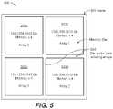
- FIG. 5illustrates a wafer-section memory circuit which can be used to form the semiconductor memory device in embodiments of the present disclosure.
- a memory circuit including a memory arrayis formed in each memory semiconductor die on a semiconductor wafer.
- a semiconductor wafer portion 501includes four adjacent or adjoining memory semiconductor dies 502 a - 502 d formed on the semiconductor wafer 501 .
- the four adjoining memory semiconductor dies 502 a - 502 dare grouped to form a wafer-section memory circuit 500 .
- the memory semiconductor dies 502 a - 502 dare separated and isolated from each other by scribe lines 504 .
- Each memory semiconductor die 502 a - 502 dincludes a memory array formed thereon.
- each memory semiconductor die 502 a - 502 dis implemented as a quasi-volatile (QV) memory circuit, as described above.
- QVquasi-volatile
- the wafer-section memory circuitincludes four memory semiconductor dies grouped in a two by two section on the wafer 501 .
- the grouping of the memory semiconductor dies in FIG. 5is illustrative only and not intended to be limiting.
- two or more memory semiconductor dies in any configurationcan be selected to form the group.
- a wafer-section memory circuitmay include any number of semiconductor dies. The selection may be made based on the capacity needs for the memory module to be formed.
- wafer-section memory circuitmay include a given number of semiconductor dies to yield a given die size.
- the wafer-section memory circuitmay be configured so that it has the same die size as the corresponding wafer-section controller circuit, as will be described in more detail below.
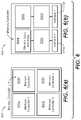
- FIG. 6which includes FIGS. 6( a ) and 6( b ) , illustrates wafer-section controller circuits which can be used to form the semiconductor memory device in embodiments of the present disclosure.
- a wafer-section controller circuitrefers to memory controller logic circuits fabricated on a memory controller die.
- the wafer-section controller circuitis formed as a wafer portion including a group of two or more memory controller dies that are separated by scribe lines.
- the wafer-section controller circuitis configured to have substantially the same area or equivalent size as the wafer-section memory circuit to be coupled thereto.
- the wafer-section controller circuitis formed as a wafer portion including a single controller die where the single controller die has a die size that matches substantially the size of the wafer-section memory circuit to be coupled thereto, as will be explained in more details below. Having the memory circuit and the controller circuit to be the same planar size makes it easier to bond the two wafer portions and to provide interconnection between the memory and the controller circuits.
- the wafer-section controller circuitis formed using a group of adjacent or adjoining memory controller semiconductor dies grouped together to form a wafer-section memory controller, as shown in FIG. 6( a ) .
- a memory controller circuitis fabricated in each memory controller semiconductor die.
- a wafer-section memory controller circuit 600includes a wafer portion of four memory controller semiconductor dies 610 a to 610 d grouped in a two by two section and arranged in the same manner as the memory semiconductor dies on the wafer-section memory circuit to which the controller circuit will be bonded.
- each memory controller semiconductor die 610 a - 610 dis separated from other controller semiconductor dies by scribe lines.
- the wafer-section controller circuitcan be formed as one memory controller die having the same planar size as the corresponding wafer-section memory circuit, as shown in FIG. 6( b ) .
- a wafer-section memory controller circuit 650includes memory logic circuit blocks 660 a to 660 d .
- Each memory logic block 660 a - 660 dincludes array interconnects for bonding to the corresponding memory circuits in the wafer-section memory circuit.
- the wafer-section memory controller circuit 650further includes one or more interface circuits 670 a and 670 b for providing input/output data access by a host system.
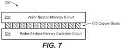
- FIG. 7illustrates a QV memory module constructed using the wafer-section memory circuit and the wafer-section controller circuit in embodiments of the present disclosure.
- a wafer-section memory circuit 702 constructed as described above using a group of memory semiconductor diesis flip-chip bonded to a wafer-section memory controller circuit 704 , such as by using hybrid bonds or copper studs 706 , to form a QV memory module 700 .
- the wafer-section memory controller circuit 704is configured as a single memory controller as shown in FIG. 6( b ) to form the QV memory module 700 being a single memory device with one controller and a large memory capacity.
- the wafer-section memory controller circuit 704is configured as a group of four memory controller semiconductor dies, as shown in FIG. 6( a ) .
- the QV memory module 700operates as four memory devices with each memory array having its own controller circuit.
- the several memory controller semiconductor diesmay be connected and gated to operate as a singular controller unit.
- the QV memory module 700offers various configuration options to enable a variety of usage applications to users.
- the QV memory module 700 of FIG. 7provides many advantages over conventional memory circuit.
- the QV memory module 700can be used as a main memory equivalent, replacing traditional DIMMs with a denser solution. Furthermore, the QV memory module can be located closer to the CPU core for better signaling characteristics and reduced power by having less RC loss in the connecting memory bus.
- the QV memory modulecan be constructed to include additional layers of wafer-section memory circuits in the stack.
- a third semiconductor wafer portionmay be stacked on the QV memory module using a wafer-section stacking technique.
- the third semiconductor wafer portionmay be interconnected with the underlying wafer-section controller circuit using through-silicon vias.
- the third semiconductor wafer portionis another wafer-section memory circuit. Accordingly, the memory capacity of the resulting QV memory module can be increased significantly by introducing another group of memory array.
- the QV memory modulehas further applications in proprietary system designs that have very demanding memory needs.
- artificial intelligence (AI) systems or machine learning systemsare prime candidates for using this type of dense memory solution.
- AI system developed with multiple number of cores and fabricated on an advanced fabrication processwould result in a very large die.
- an application-specific memory moduleis formed by connecting an application-specific logic circuit to the QV memory module formed as the semiconductor memory device described above.
- FIG. 8illustrates a stacked application-specific memory module in embodiments of the present disclosure.
- a stacked application-specific memory module 800is formed by a QV memory module 810 coupled to an application-specific logic circuit 820 .
- the QV memory module 810may be constructed in the same manner described above and may include a wafer-section memory circuit 812 flip-chip bonded to a wafer-section controller circuit 814 .
- a third semiconductor component 820is stacked on the QV memory module using a die stacking technique.
- the third semiconductor component 820is bounded to the wafer-section memory circuit 812 .
- Through silicon vias 830 formed in the wafer-section memory circuit 812provide connections from the third semiconductor component 820 to the wafer-section controller circuit 814 under the wafer-section memory circuit 812 .
- the third semiconductor component 820is another wafer-section memory circuit.
- the stacked application-specific memory module 800is formed with stacked memory circuits to dramatically increase the memory capacity provided by the module.
- the third semiconductor component 820is an application-specific logic circuit.
- the application-specific logic circuitcan be an AI processing core or a machine learning processing core.
- the stacked application-specific memory module 800enables the application-specific logic circuitry to be provided with high density memory which is formed directly adjacent to the logic circuit.
- the wafer-section memory circuit 812may provide very high-density memory in the 128 Gb or 256 Gb range per memory die in the memory circuit.
- the memory capacityis provided off the application-specific logic circuit and only requires the application-specific logic circuit to provide area for connecting to the memory circuit.
- the wafer-section controller circuit 814includes a SRAM circuit 840 formed thereon.
- the application-specific logic circuit 820may access the SRAM circuit 840 in the controller circuit 814 through through-silicon vias formed in the intervening memory circuit wafer 812 and copper studs formed on the memory circuit 812 for connection to the controller circuit 814 .
- the QV memory modulenot only offers high memory capacity, the QV memory module is also designed to read and write in pages of access.
- the memory cells in the QV memory moduleis organized in a tile structure with each tile acting as a small memory circuit on its own. By configuring these tiles, it is possible to have data pages of a width needed to meet the throughput of very demanding applications. For example, a 2 KB page is possible so an AI processor design will not be limited by the normal memory bottleneck that typical DRAM suffers.
- the application-specific logic circuitalso has access to the different blocks of memory as these signals are brought into the third semiconductor component for use. By having the block signaling available to a designer, the memory structure can be changed to fit the application needs, offering a user-defined memory structure, something not possible with a traditional memory bus structure.
- the application-specific logic circuit 820may also tap into the SRAM 840 formed on the memory controller circuit 814 .
- the SRAM 840like the memory circuit 812 , can be routed to the application-specific logic circuit 820 to implement the application-specific designs.
- the routingwhich can be realized by copper studs and TSV signaling, will provide very fast signaling.
- the application-specific logic circuit 820is connected to the memory circuit 812 through TSVs and in addition may need to have its own input/output signaling.
- generic arrays 850 of through-silicon viascan be formed on and spread across the wafer-section memory circuit 812 to provide I/O connections to the application-specific logic circuit 820 .
- the TSV arrays 850may be built to connect to unused copper studs of the memory circuit 812 .
- the TSV arrays 850can be used as I/O lines to connect the input/output signals of the application-specific logic circuit 820 to the controller circuit 814 where the input/output signals can be provided to systems outside of the module 800 .
- the TSV arrays 850can also be employed as conduits for power distribution networks from the memory controller circuit 814 or the memory circuit 812 to the application-specific logic circuit 820 to distribute power throughout the application-specific logic circuit 820 .
- the stacked application-specific memory modulemay include two or more wafer-section memory circuits stacked on each other to provide increased memory capacity. Furthermore, in other embodiments, the stacked application-specific memory module may further include an application-specific logic circuit bounded on the two or more wafer-section memory circuits. Accordingly, in embodiments of the present disclosure, the stacked application-specific memory module may be constructed to include a wafer-section controller circuit with one or more wafer-section memory circuits formed there on and at least one application-specific logic circuit formed on the stack. The large capacity of the memory circuits can be accessed as a regular memory device through the controller circuit. Furthermore, a portion of the memory capacity may be used by the application-specific logic circuit for more efficient processing operation, for example in applications such as artificial intelligence or machine learning.
- the wafer-section memory circuitis formed by a group of memory semiconductor dies formed on a common semiconductor substrate and separated by scribe lines. By nature of being separated by the scribe lines, the memory semiconductor dies are not connected to each other. In embodiments of the present disclosure, structures and methods for interconnecting the memory dies that are separated by scribe lines are described.
- FIG. 9illustrates one method of semiconductor die interconnection that can be implemented in the QV memory module in embodiments of the present disclosure.
- a QV memory module 900includes two or more wafer-section memory circuits 902 , 904 stacked on top of each other and a third semiconductor layer 906 .
- the third semiconductor layer 906being the topmost semiconductor layer, may be another wafer-section memory circuit or an application-specific logic circuit.
- one or more logic bridge circuits 910are formed on the topmost semiconductor layer 906 .
- Data buses 920such as formed by copper studs, hybrid bonds and TSVs, provide a signal pathway for connecting signals across the scribe lines between the memory semiconductor dies. In this manner, one memory circuit (e.g.
- memory array 0can communicate with an adjacent or nearby memory circuit (e.g. memory array 1 ).
- signals that are shared or common among the memory semiconductor diescan be connected to the signal pathway to enable certain ordered connections to be made.
- FIG. 9other copper studs and TSV's are omitted and only the data buses 920 and the logic bridge circuit are shown.
- the QV memory module 900includes two stacked wafer-section memory circuits 902 and 904 while the third semiconductor layer 906 provides the logic bridges for connecting memory circuits across scribe lines.
- the embodiment shown in FIG. 9is illustrative only and not intended to be limiting.
- the QV memory modulemay include a single layer of wafer-section memory circuit and the logic bridges 910 are formed in a second semiconductor layer stacked on the wafer-section memory circuit.
- the topmost semiconductor layer 906is implemented as a field programmable gate array (FPGA) which includes programmable connections as the logic bridge circuits.
- FPGAfield programmable gate array
- the FPGAprovides routing options based on a program connect methodology that can be used to enable and disable signals to the bridge bus 920 .
- the memory arrayscan be made to operate in different ways based on the application needs.
Landscapes
- Engineering & Computer Science (AREA)
- Microelectronics & Electronic Packaging (AREA)
- Power Engineering (AREA)
- Physics & Mathematics (AREA)
- Condensed Matter Physics & Semiconductors (AREA)
- General Physics & Mathematics (AREA)
- Computer Hardware Design (AREA)
- Semiconductor Memories (AREA)
- Dram (AREA)
Abstract
Description
Claims (20)
Priority Applications (1)
| Application Number | Priority Date | Filing Date | Title |
|---|---|---|---|
| US17/124,194US11508693B2 (en) | 2020-02-24 | 2020-12-16 | High capacity memory module including wafer-section memory circuit |
Applications Claiming Priority (2)
| Application Number | Priority Date | Filing Date | Title |
|---|---|---|---|
| US202062980592P | 2020-02-24 | 2020-02-24 | |
| US17/124,194US11508693B2 (en) | 2020-02-24 | 2020-12-16 | High capacity memory module including wafer-section memory circuit |
Publications (2)
| Publication Number | Publication Date |
|---|---|
| US20210265308A1 US20210265308A1 (en) | 2021-08-26 |
| US11508693B2true US11508693B2 (en) | 2022-11-22 |
Family
ID=77366462
Family Applications (1)
| Application Number | Title | Priority Date | Filing Date |
|---|---|---|---|
| US17/124,194ActiveUS11508693B2 (en) | 2020-02-24 | 2020-12-16 | High capacity memory module including wafer-section memory circuit |
Country Status (3)
| Country | Link |
|---|---|
| US (1) | US11508693B2 (en) |
| TW (1) | TWI767489B (en) |
| WO (1) | WO2021173209A1 (en) |
Cited By (1)
| Publication number | Priority date | Publication date | Assignee | Title |
|---|---|---|---|---|
| US20220199643A1 (en)* | 2017-06-20 | 2022-06-23 | Sunrise Memory Corporation | 3-dimensional nor memory array architecture and methods for fabrication thereof |
Families Citing this family (19)
| Publication number | Priority date | Publication date | Assignee | Title |
|---|---|---|---|---|
| US11120884B2 (en) | 2015-09-30 | 2021-09-14 | Sunrise Memory Corporation | Implementing logic function and generating analog signals using NOR memory strings |
| WO2020160169A1 (en) | 2019-01-30 | 2020-08-06 | Sunrise Memory Corporation | Device with embedded high-bandwidth, high-capacity memory using wafer bonding |
| EP3925004A4 (en) | 2019-02-11 | 2023-03-08 | Sunrise Memory Corporation | VERTICAL THIN-FILM TRANSISTOR AND APPLICATION AS A BITLINE CONNECTOR FOR THREE-DIMENSIONAL MEMORY ARRAYS |
| WO2021127218A1 (en) | 2019-12-19 | 2021-06-24 | Sunrise Memory Corporation | Process for preparing a channel region of a thin-film transistor |
| WO2021158994A1 (en) | 2020-02-07 | 2021-08-12 | Sunrise Memory Corporation | Quasi-volatile system-level memory |
| TWI836184B (en) | 2020-02-07 | 2024-03-21 | 美商森恩萊斯記憶體公司 | High capacity memory circuit with low effective latency |
| US11508693B2 (en) | 2020-02-24 | 2022-11-22 | Sunrise Memory Corporation | High capacity memory module including wafer-section memory circuit |
| US11507301B2 (en) | 2020-02-24 | 2022-11-22 | Sunrise Memory Corporation | Memory module implementing memory centric architecture |
| WO2022108848A1 (en) | 2020-11-17 | 2022-05-27 | Sunrise Memory Corporation | Methods for reducing disturb errors by refreshing data alongside programming or erase operations |
| WO2022173700A1 (en) | 2021-02-10 | 2022-08-18 | Sunrise Memory Corporation | Memory interface with configurable high-speed serial data lanes for high bandwidth memory |
| US11855057B2 (en)* | 2021-07-08 | 2023-12-26 | Taiwan Semiconductor Manufacturing Company, Ltd. | Package structure and method of forming the same |
| TW202310429A (en) | 2021-07-16 | 2023-03-01 | 美商日升存儲公司 | 3-dimensional memory string array of thin-film ferroelectric transistors |
| US11721385B2 (en)* | 2021-08-12 | 2023-08-08 | Micron Technology, Inc. | Dynamic power distribution for stacked memory |
| US12402319B2 (en) | 2021-09-14 | 2025-08-26 | Sunrise Memory Corporation | Three-dimensional memory string array of thin-film ferroelectric transistors formed with an oxide semiconductor channel |
| US11974422B2 (en)* | 2021-11-04 | 2024-04-30 | Taiwan Semiconductor Manufacturing Company, Ltd. | Semiconductor device |
| TWI828052B (en)* | 2022-01-27 | 2024-01-01 | 鯨鏈科技股份有限公司 | Computer system and memory management method based on wafer-on-wafer architecture |
| US20230262988A1 (en)* | 2022-02-14 | 2023-08-17 | Sunrise Memory Corporation | Memory structure including three-dimensional nor memory strings of junctionless ferroelectric memory transistors and method of fabrication |
| JP2023167896A (en)* | 2022-05-13 | 2023-11-24 | キオクシア株式会社 | memory system |
| US20240321668A1 (en)* | 2023-03-21 | 2024-09-26 | Advanced Micro Devices, Inc. | Temperature sensors in die pair topology |
Citations (114)
| Publication number | Priority date | Publication date | Assignee | Title |
|---|---|---|---|---|
| US4213139A (en) | 1978-05-18 | 1980-07-15 | Texas Instruments Incorporated | Double level polysilicon series transistor cell |
| US5583808A (en) | 1994-09-16 | 1996-12-10 | National Semiconductor Corporation | EPROM array segmented for high performance and method for controlling same |
| US5646886A (en) | 1995-05-24 | 1997-07-08 | National Semiconductor Corporation | Flash memory having segmented array for improved operation |
| US5768192A (en) | 1996-07-23 | 1998-06-16 | Saifun Semiconductors, Ltd. | Non-volatile semiconductor memory cell utilizing asymmetrical charge trapping |
| US5789776A (en) | 1995-09-22 | 1998-08-04 | Nvx Corporation | Single poly memory cell and array |
| US5915167A (en) | 1997-04-04 | 1999-06-22 | Elm Technology Corporation | Three dimensional structure memory |
| US6040605A (en) | 1998-01-28 | 2000-03-21 | Hitachi, Ltd. | Semiconductor memory device |
| US6130838A (en) | 1997-08-12 | 2000-10-10 | Samsung Electronics, Co., Ltd. | Structure nonvolatile semiconductor memory cell array and method for fabricating same |
| US20010030340A1 (en) | 1998-11-04 | 2001-10-18 | Ichiro Fujiwara | Nonvolatile semiconductor memory device and process of production and write method thereof |
| US6314046B1 (en) | 1999-03-30 | 2001-11-06 | Sanyo Electric Co., Ltd. | Dual memory control circuit |
| US20010053092A1 (en) | 2000-06-12 | 2001-12-20 | Sony Corporation | Memory system and programming method thereof |
| US20020051378A1 (en) | 2000-08-17 | 2002-05-02 | Takashi Ohsawa | Semiconductor memory device and method of manufacturing the same |
| US6434053B1 (en) | 1999-12-06 | 2002-08-13 | Sony Corporation | Nonvolatile semiconductor memory device and method of operation thereof |
| US20020193484A1 (en) | 2001-02-02 | 2002-12-19 | The 54 Group, Ltd. | Polymeric resins impregnated with insect repellants |
| US6580124B1 (en) | 2000-08-14 | 2003-06-17 | Matrix Semiconductor Inc. | Multigate semiconductor device with vertical channel current and method of fabrication |
| US6744094B2 (en) | 2001-08-24 | 2004-06-01 | Micron Technology Inc. | Floating gate transistor with horizontal gate layers stacked next to vertical body |
| US6774458B2 (en) | 2002-07-23 | 2004-08-10 | Hewlett Packard Development Company, L.P. | Vertical interconnection structure and methods |
| US20040214387A1 (en) | 2002-07-08 | 2004-10-28 | Madurawe Raminda Udaya | Methods for fabricating three dimensional integrated circuits |
| US20040246807A1 (en) | 2003-06-03 | 2004-12-09 | Seung-Hoon Lee | Multi-port memory device with stacked banks |
| US20040262772A1 (en) | 2003-06-30 | 2004-12-30 | Shriram Ramanathan | Methods for bonding wafers using a metal interlayer |
| US6873004B1 (en) | 2002-02-04 | 2005-03-29 | Nexflash Technologies, Inc. | Virtual ground single transistor memory cell, memory array incorporating same, and method of operation thereof |
| US20050128815A1 (en) | 2003-12-09 | 2005-06-16 | Renesas Technology Corp. | Semiconductor data processing device |
| US6946703B2 (en) | 2003-01-09 | 2005-09-20 | Samsung Electronics Co., Ltd. | SONOS memory device having side gate stacks and method of manufacturing the same |
| US7005350B2 (en) | 2002-12-31 | 2006-02-28 | Matrix Semiconductor, Inc. | Method for fabricating programmable memory array structures incorporating series-connected transistor strings |
| US20060155921A1 (en) | 2004-12-16 | 2006-07-13 | Gorobets Sergey A | Non-volatile memory and method with multi-stream update tracking |
| US7284226B1 (en)* | 2004-10-01 | 2007-10-16 | Xilinx, Inc. | Methods and structures of providing modular integrated circuits |
| US7307308B2 (en) | 2003-04-07 | 2007-12-11 | Silicon Storage Technology, Inc. | Buried bit line non-volatile floating gate memory cell with independent controllable control gate in a trench, and array thereof, and method of formation |
| US20080239812A1 (en) | 2007-03-30 | 2008-10-02 | Kabushiki Kaisha Toshiba | Nonvolatile semiconductor memory system |
| US20080301359A1 (en) | 2004-12-16 | 2008-12-04 | Peter John Smith | Non-Volatile Memory and Method With Multi-Stream Updating |
| US20090157946A1 (en) | 2007-12-12 | 2009-06-18 | Siamak Arya | Memory having improved read capability |
| US20090237996A1 (en) | 2008-03-20 | 2009-09-24 | Micron Technology, Inc. | Memory structure having volatile and non-volatile memory portions |
| US7612411B2 (en) | 2005-08-03 | 2009-11-03 | Walker Andrew J | Dual-gate device and method |
| US20090279360A1 (en) | 2008-05-07 | 2009-11-12 | Aplus Flash Technology, Inc. | NAND based NMOS NOR flash memory cell, a NAND based NMOS nor flash memory array, and a method of forming a NAND based NMOS NOR flash memory array |
| US20090290442A1 (en) | 2005-06-24 | 2009-11-26 | Rajan Suresh N | Method and circuit for configuring memory core integrated circuit dies with memory interface integrated circuit dies |
| US20090316487A1 (en) | 2008-06-20 | 2009-12-24 | Aplus Flash Technology, Inc. | Apparatus and method for inhibiting excess leakage current in unselected nonvolatile memory cells in an array |
| JP2010108522A (en) | 2010-02-02 | 2010-05-13 | Toshiba Corp | Method of controlling memory system |
| US20100121994A1 (en) | 2008-11-10 | 2010-05-13 | International Business Machines Corporation | Stacked memory array |
| US20100124116A1 (en) | 2008-11-14 | 2010-05-20 | Kabushiki Kaisha Toshiba | Non-volatile semiconductor storage device |
| US20100128509A1 (en) | 2008-11-25 | 2010-05-27 | Sukpil Kim | Three-Dimensional Semiconductor Devices and Methods of Operating the Same |
| JP2011028540A (en) | 2009-07-27 | 2011-02-10 | Renesas Electronics Corp | Information processing system, method for controlling cache memory, program and compiler |
| US20110044113A1 (en) | 2009-08-18 | 2011-02-24 | Samsung Electronics Co., Ltd. | Nonvolatile memory device, method for programming same, and memory system incorporating same |
| US20110134705A1 (en) | 2009-12-07 | 2011-06-09 | Stmicroelectronics (R&D) Ltd | Integrated circuit package with multiple dies and a multiplexed communications interface |
| US20110170266A1 (en) | 2010-01-08 | 2011-07-14 | Ibm Corporation | 4d device process and structure |
| US20110208905A1 (en) | 2008-12-09 | 2011-08-25 | Rambus Inc. | Non-Volatile Memory Device For Concurrent And Pipelined Memory Operations |
| US8026521B1 (en) | 2010-10-11 | 2011-09-27 | Monolithic 3D Inc. | Semiconductor device and structure |
| US20110298013A1 (en) | 2010-06-07 | 2011-12-08 | Samsung Electronics Co., Ltd. | Vertical Structure Semiconductor Memory Devices And Methods Of Manufacturing The Same |
| US20110310683A1 (en) | 2001-09-28 | 2011-12-22 | Micron Technology, Inc. | Non-volatile memory control |
| US8178396B2 (en) | 2009-03-11 | 2012-05-15 | Micron Technology, Inc. | Methods for forming three-dimensional memory devices, and related structures |
| US20120182801A1 (en) | 2011-01-19 | 2012-07-19 | Macronix International Co., Ltd. | Memory Architecture of 3D NOR Array |
| KR20120085591A (en) | 2011-01-24 | 2012-08-01 | 김진선 | Non-volatile memory device, method of operating the same, and method of fabricating the same |
| US20120243314A1 (en) | 2011-03-25 | 2012-09-27 | Kabushiki Kaisha Toshiba | Nonvolatile semiconductor memory device |
| US20130031325A1 (en) | 2011-07-29 | 2013-01-31 | The Boeing Company | System for Updating an Associative Memory |
| US20130256780A1 (en) | 2012-03-30 | 2013-10-03 | Kabushiki Kaisha Toshiba | Semiconductor device and manufacturing method thereof |
| US20140040698A1 (en) | 2012-08-06 | 2014-02-06 | Advanced Micro Devices, Inc. | Stacked memory device with metadata mangement |
| US8653672B2 (en)* | 1997-04-04 | 2014-02-18 | Glenn J Leedy | Three dimensional structure memory |
| US20140075135A1 (en) | 2012-09-11 | 2014-03-13 | Samsung Electronics Co., Ltd. | Semiconductor memory device with operation functions |
| US20140117366A1 (en) | 2012-10-31 | 2014-05-01 | Kabushiki Kaisha Toshiba | Semiconductor device and method for manufacturing same |
| US20140151774A1 (en) | 2012-12-04 | 2014-06-05 | Mosaid Technologies Incorporated | Nand flash memory with vertical cell stack structure and method for manufacturing same |
| US8767473B2 (en) | 2009-06-19 | 2014-07-01 | Samsung Electronics Co., Ltd. | Programming methods for three-dimensional memory devices having multi-bit programming, and three-dimensional memory devices programmed thereby |
| US20140229131A1 (en) | 2012-05-04 | 2014-08-14 | Lsi Corporation | Retention-drift-history-based non-volatile memory read threshold optimization |
| US8848425B2 (en) | 2008-12-19 | 2014-09-30 | Unity Semiconductor Corporation | Conductive metal oxide structures in non volatile re-writable memory devices |
| US8878278B2 (en) | 2012-03-21 | 2014-11-04 | Sandisk Technologies Inc. | Compact three dimensional vertical NAND and method of making thereof |
| US20140328128A1 (en) | 2013-05-01 | 2014-11-06 | Zeno Semiconductor, Inc. | NAND String Utilizing Floating Body Memory Cell |
| US20140340952A1 (en) | 2013-05-17 | 2014-11-20 | Micron Technology, Inc. | Apparatuses having a ferroelectric field-effect transistor memory array and related method |
| US20150098272A1 (en) | 2013-10-03 | 2015-04-09 | Apple Inc. | Programmable peak-current control in non-volatile memory devices |
| US20150113214A1 (en) | 2013-10-21 | 2015-04-23 | Sehat Sutardja | Final level cache system and corresponding methods |
| US20150155876A1 (en)* | 2012-08-06 | 2015-06-04 | Advanced Micro Devices, Inc. | Die-stacked memory device with reconfigurable logic |
| US20150194440A1 (en) | 2014-01-09 | 2015-07-09 | Young-Jin Noh | Nonvolatile Memory Devices And Methods Of Fabricating The Same |
| US20150263005A1 (en) | 2013-07-10 | 2015-09-17 | Galaxycore Shanghai Limited Corporation | Dynamic Random Access Memory (DRAM) and Production Method, Semiconductor Packaging Component and Packaging Method |
| US9190293B2 (en) | 2013-12-18 | 2015-11-17 | Applied Materials, Inc. | Even tungsten etch for high aspect ratio trenches |
| US20160013156A1 (en) | 2014-07-14 | 2016-01-14 | Apple Inc. | Package-on-package options with multiple layer 3-d stacking |
| US20160019951A1 (en) | 2014-07-18 | 2016-01-21 | Samsung Electronics Co., Ltd. | Resistive memory device, resistive memory system, and method of operating resistive memory device |
| US20160035711A1 (en) | 2014-07-29 | 2016-02-04 | Dyi-chung Hu | Stacked package-on-package memory devices |
| US20160086970A1 (en) | 2014-09-23 | 2016-03-24 | Haibing Peng | Three-dimensional non-volatile nor-type flash memory |
| US9412752B1 (en) | 2015-09-22 | 2016-08-09 | Macronix International Co., Ltd. | Reference line and bit line structure for 3D memory |
| US20160300724A1 (en) | 2007-05-25 | 2016-10-13 | Cypress Semiconductor Corporation | Oxide-Nitride-Oxide Stack Having Multiple Oxynitride Layers |
| US20160314042A1 (en) | 2015-04-27 | 2016-10-27 | Invensas Corporation | Preferred state encoding in non-volatile memories |
| US20170092371A1 (en) | 2015-09-30 | 2017-03-30 | Eli Harari | Capacitive-coupled non-volatile thin-film transistor strings in three dimensional arrays |
| US20170092370A1 (en) | 2015-09-30 | 2017-03-30 | Eli Harari | Multi-gate nor flash thin-film transistor strings arranged in stacked horizontal active strips with vertical control gates |
| US20170148517A1 (en) | 2015-11-25 | 2017-05-25 | Eli Harari | Three-dimensional vertical nor flash thin film transistor strings |
| US20170148810A1 (en) | 2015-11-20 | 2017-05-25 | Sandisk Technologies Llc | Three-dimensional nand device containing support pedestal structures for a buried source line and method of making the same |
| US20170213821A1 (en) | 2014-08-26 | 2017-07-27 | Monolithic 3D Inc. | 3d semiconductor device and structure |
| US9748172B2 (en) | 2015-02-25 | 2017-08-29 | Sandisk Technologies Llc | Floating staircase word lines and process in a 3D non-volatile memory having vertical bit lines |
| US9799761B2 (en) | 2013-03-11 | 2017-10-24 | Monolithic 3D Inc. | 3DIC based system with memory cells and transistors |
| US20170358594A1 (en) | 2016-06-13 | 2017-12-14 | Sandisk Technologies Llc | Method of forming a staircase in a semiconductor device using a linear alignmnent control feature |
| US20180095127A1 (en) | 2016-09-30 | 2018-04-05 | Intel Corporation | Systems, methods, and apparatuses for implementing testing of fault repairs to a through silicon via (tsv) in two-level memory (2lm) stacked die subsystems |
| US10074667B1 (en) | 2017-03-10 | 2018-09-11 | Toshiba Memory Corporation | Semiconductor memory device |
| US20180269229A1 (en) | 2015-09-21 | 2018-09-20 | Monolithic 3D Inc. | 3D Semiconductor Device and Structure |
| US20180331042A1 (en) | 2015-12-23 | 2018-11-15 | Mathew J. Manusharow | Size and efficiency of dies |
| US20180366489A1 (en) | 2017-06-20 | 2018-12-20 | Sunrise Memory Corporation | 3-Dimensional NOR Memory Array Architecture and Methods for Fabrication Thereof |
| US20180366471A1 (en) | 2017-06-20 | 2018-12-20 | Sunrise Memory Corporation | 3-Dimensional NOR String Arrays in Segmented Stacks |
| US20190019564A1 (en) | 2017-07-13 | 2019-01-17 | Qualcomm Incorporated | Multiple (multi-) level cell (mlc) non-volatile (nv) memory (nvm) matrix circuits for performing matrix computations with multi-bit input vectors |
| US10254968B1 (en) | 2015-06-10 | 2019-04-09 | Firquest Llc | Hybrid memory device for lookup operations |
| US10283493B1 (en) | 2018-01-17 | 2019-05-07 | Sandisk Technologies Llc | Three-dimensional memory device containing bonded memory die and peripheral logic die and method of making thereof |
| US20190171391A1 (en)* | 2017-12-06 | 2019-06-06 | Western Digital Technologies, Inc. | Volatility management for non-volatile memory device |
| US10319696B1 (en)* | 2018-05-10 | 2019-06-11 | Micron Technology, Inc. | Methods for fabricating 3D semiconductor device packages, resulting packages and systems incorporating such packages |
| US20190206890A1 (en) | 2017-12-28 | 2019-07-04 | Sunrise Memory Corporation | 3-Dimensional NOR Memory Array with Very Fine Pitch: Device and Method |
| US20190214077A1 (en) | 2005-09-30 | 2019-07-11 | Conversant Intellectual Property Management Inc. | Memory with output control |
| US20190238134A1 (en) | 2017-09-12 | 2019-08-01 | iCometrue Company Ltd. | Logic drive with brain-like elasticity and integrality based on standard commodity fpga ic chips using non-volatile memory cells |
| US20190244971A1 (en) | 2018-02-02 | 2019-08-08 | Sunrise Memory Corporation | Three-dimensional vertical NOR Flash Thin-Film Transistor Strings |
| US10381370B2 (en) | 2013-11-08 | 2019-08-13 | Samsung Electronics Co., Ltd. | Semiconductor device |
| US10431596B2 (en) | 2017-08-28 | 2019-10-01 | Sunrise Memory Corporation | Staggered word line architecture for reduced disturb in 3-dimensional NOR memory arrays |
| US20190303042A1 (en) | 2018-03-30 | 2019-10-03 | Samsung Electronics Co., Ltd. | Memory device sampling data using control signal transmitted through tsv |
| US20190319044A1 (en) | 2018-02-02 | 2019-10-17 | Sunrise Memory Corporation | Three-dimensional vertical NOR Flash Thin-Film Transistor Strings |
| US20190325945A1 (en) | 2018-04-20 | 2019-10-24 | Taiwan Semiconductor Manufacturing Company, Ltd. | Memory cell array and method of manufacturing same |
| US20190370117A1 (en) | 2016-06-28 | 2019-12-05 | International Business Machines Corporation | File level access to block level incremental backups of a virtual disk |
| US20200051990A1 (en) | 2018-07-12 | 2020-02-13 | Sunrise Memory Corporation | Device Structure for a 3-Dimensional NOR Memory Array and Methods for Improved Erase Operations Applied Thereto |
| US20200098779A1 (en) | 2018-09-20 | 2020-03-26 | Sunrise Memory Corporation | Staircase Structures for Electrically Connecting Multiple Horizontal Conductive Layers of a 3-Dimensional Memory Device |
| US20200176468A1 (en) | 2018-12-04 | 2020-06-04 | Sunrise Memory Corporation | Methods for forming multilayer horizontal nor-type thin-film memory strings |
| US10692837B1 (en)* | 2018-07-20 | 2020-06-23 | Xilinx, Inc. | Chip package assembly with modular core dice |
| US20200243486A1 (en) | 2019-01-30 | 2020-07-30 | Sunrise Memory Corporation | Device with embedded high-bandwidth, high-capacity memory using wafer bonding |
| US20210247910A1 (en) | 2020-02-07 | 2021-08-12 | Sunrise Memory Corporation | High capacity memory circuit with low effective latency |
| US20210248094A1 (en) | 2020-02-07 | 2021-08-12 | Sunrise Memory Corporation | Quasi-volatile system-level memory |
| US20210265308A1 (en) | 2020-02-24 | 2021-08-26 | Sunrise Memory Corporation | High capacity memory module including wafer-section memory circuit |
- 2020
- 2020-12-16USUS17/124,194patent/US11508693B2/enactiveActive
- 2020-12-16WOPCT/US2020/065374patent/WO2021173209A1/ennot_activeCeased
- 2021
- 2021-01-04TWTW110100034Apatent/TWI767489B/enactive
Patent Citations (131)
| Publication number | Priority date | Publication date | Assignee | Title |
|---|---|---|---|---|
| US4213139A (en) | 1978-05-18 | 1980-07-15 | Texas Instruments Incorporated | Double level polysilicon series transistor cell |
| US5583808A (en) | 1994-09-16 | 1996-12-10 | National Semiconductor Corporation | EPROM array segmented for high performance and method for controlling same |
| US5646886A (en) | 1995-05-24 | 1997-07-08 | National Semiconductor Corporation | Flash memory having segmented array for improved operation |
| US5789776A (en) | 1995-09-22 | 1998-08-04 | Nvx Corporation | Single poly memory cell and array |
| US5768192A (en) | 1996-07-23 | 1998-06-16 | Saifun Semiconductors, Ltd. | Non-volatile semiconductor memory cell utilizing asymmetrical charge trapping |
| US8653672B2 (en)* | 1997-04-04 | 2014-02-18 | Glenn J Leedy | Three dimensional structure memory |
| US5915167A (en) | 1997-04-04 | 1999-06-22 | Elm Technology Corporation | Three dimensional structure memory |
| US6130838A (en) | 1997-08-12 | 2000-10-10 | Samsung Electronics, Co., Ltd. | Structure nonvolatile semiconductor memory cell array and method for fabricating same |
| US6040605A (en) | 1998-01-28 | 2000-03-21 | Hitachi, Ltd. | Semiconductor memory device |
| US20010030340A1 (en) | 1998-11-04 | 2001-10-18 | Ichiro Fujiwara | Nonvolatile semiconductor memory device and process of production and write method thereof |
| US6314046B1 (en) | 1999-03-30 | 2001-11-06 | Sanyo Electric Co., Ltd. | Dual memory control circuit |
| US6434053B1 (en) | 1999-12-06 | 2002-08-13 | Sony Corporation | Nonvolatile semiconductor memory device and method of operation thereof |
| US20010053092A1 (en) | 2000-06-12 | 2001-12-20 | Sony Corporation | Memory system and programming method thereof |
| US6580124B1 (en) | 2000-08-14 | 2003-06-17 | Matrix Semiconductor Inc. | Multigate semiconductor device with vertical channel current and method of fabrication |
| US20020051378A1 (en) | 2000-08-17 | 2002-05-02 | Takashi Ohsawa | Semiconductor memory device and method of manufacturing the same |
| US20020193484A1 (en) | 2001-02-02 | 2002-12-19 | The 54 Group, Ltd. | Polymeric resins impregnated with insect repellants |
| US6744094B2 (en) | 2001-08-24 | 2004-06-01 | Micron Technology Inc. | Floating gate transistor with horizontal gate layers stacked next to vertical body |
| US20110310683A1 (en) | 2001-09-28 | 2011-12-22 | Micron Technology, Inc. | Non-volatile memory control |
| US6873004B1 (en) | 2002-02-04 | 2005-03-29 | Nexflash Technologies, Inc. | Virtual ground single transistor memory cell, memory array incorporating same, and method of operation thereof |
| US20040214387A1 (en) | 2002-07-08 | 2004-10-28 | Madurawe Raminda Udaya | Methods for fabricating three dimensional integrated circuits |
| US6774458B2 (en) | 2002-07-23 | 2004-08-10 | Hewlett Packard Development Company, L.P. | Vertical interconnection structure and methods |
| US7005350B2 (en) | 2002-12-31 | 2006-02-28 | Matrix Semiconductor, Inc. | Method for fabricating programmable memory array structures incorporating series-connected transistor strings |
| US6946703B2 (en) | 2003-01-09 | 2005-09-20 | Samsung Electronics Co., Ltd. | SONOS memory device having side gate stacks and method of manufacturing the same |
| US7307308B2 (en) | 2003-04-07 | 2007-12-11 | Silicon Storage Technology, Inc. | Buried bit line non-volatile floating gate memory cell with independent controllable control gate in a trench, and array thereof, and method of formation |
| US20040246807A1 (en) | 2003-06-03 | 2004-12-09 | Seung-Hoon Lee | Multi-port memory device with stacked banks |
| US20040262772A1 (en) | 2003-06-30 | 2004-12-30 | Shriram Ramanathan | Methods for bonding wafers using a metal interlayer |
| US20050128815A1 (en) | 2003-12-09 | 2005-06-16 | Renesas Technology Corp. | Semiconductor data processing device |
| US7284226B1 (en)* | 2004-10-01 | 2007-10-16 | Xilinx, Inc. | Methods and structures of providing modular integrated circuits |
| US20060155921A1 (en) | 2004-12-16 | 2006-07-13 | Gorobets Sergey A | Non-volatile memory and method with multi-stream update tracking |
| US20080301359A1 (en) | 2004-12-16 | 2008-12-04 | Peter John Smith | Non-Volatile Memory and Method With Multi-Stream Updating |
| US20090290442A1 (en) | 2005-06-24 | 2009-11-26 | Rajan Suresh N | Method and circuit for configuring memory core integrated circuit dies with memory interface integrated circuit dies |
| US7612411B2 (en) | 2005-08-03 | 2009-11-03 | Walker Andrew J | Dual-gate device and method |
| US20190214077A1 (en) | 2005-09-30 | 2019-07-11 | Conversant Intellectual Property Management Inc. | Memory with output control |
| US20080239812A1 (en) | 2007-03-30 | 2008-10-02 | Kabushiki Kaisha Toshiba | Nonvolatile semiconductor memory system |
| US20160300724A1 (en) | 2007-05-25 | 2016-10-13 | Cypress Semiconductor Corporation | Oxide-Nitride-Oxide Stack Having Multiple Oxynitride Layers |
| US20090157946A1 (en) | 2007-12-12 | 2009-06-18 | Siamak Arya | Memory having improved read capability |
| US20090237996A1 (en) | 2008-03-20 | 2009-09-24 | Micron Technology, Inc. | Memory structure having volatile and non-volatile memory portions |
| US20090279360A1 (en) | 2008-05-07 | 2009-11-12 | Aplus Flash Technology, Inc. | NAND based NMOS NOR flash memory cell, a NAND based NMOS nor flash memory array, and a method of forming a NAND based NMOS NOR flash memory array |
| US20090316487A1 (en) | 2008-06-20 | 2009-12-24 | Aplus Flash Technology, Inc. | Apparatus and method for inhibiting excess leakage current in unselected nonvolatile memory cells in an array |
| US20100121994A1 (en) | 2008-11-10 | 2010-05-13 | International Business Machines Corporation | Stacked memory array |
| US20100124116A1 (en) | 2008-11-14 | 2010-05-20 | Kabushiki Kaisha Toshiba | Non-volatile semiconductor storage device |
| US20100128509A1 (en) | 2008-11-25 | 2010-05-27 | Sukpil Kim | Three-Dimensional Semiconductor Devices and Methods of Operating the Same |
| US20110208905A1 (en) | 2008-12-09 | 2011-08-25 | Rambus Inc. | Non-Volatile Memory Device For Concurrent And Pipelined Memory Operations |
| US8848425B2 (en) | 2008-12-19 | 2014-09-30 | Unity Semiconductor Corporation | Conductive metal oxide structures in non volatile re-writable memory devices |
| US8178396B2 (en) | 2009-03-11 | 2012-05-15 | Micron Technology, Inc. | Methods for forming three-dimensional memory devices, and related structures |
| US8767473B2 (en) | 2009-06-19 | 2014-07-01 | Samsung Electronics Co., Ltd. | Programming methods for three-dimensional memory devices having multi-bit programming, and three-dimensional memory devices programmed thereby |
| JP2011028540A (en) | 2009-07-27 | 2011-02-10 | Renesas Electronics Corp | Information processing system, method for controlling cache memory, program and compiler |
| US20110044113A1 (en) | 2009-08-18 | 2011-02-24 | Samsung Electronics Co., Ltd. | Nonvolatile memory device, method for programming same, and memory system incorporating same |
| US20110134705A1 (en) | 2009-12-07 | 2011-06-09 | Stmicroelectronics (R&D) Ltd | Integrated circuit package with multiple dies and a multiplexed communications interface |
| US20110170266A1 (en) | 2010-01-08 | 2011-07-14 | Ibm Corporation | 4d device process and structure |
| JP2010108522A (en) | 2010-02-02 | 2010-05-13 | Toshiba Corp | Method of controlling memory system |
| US20110298013A1 (en) | 2010-06-07 | 2011-12-08 | Samsung Electronics Co., Ltd. | Vertical Structure Semiconductor Memory Devices And Methods Of Manufacturing The Same |
| US8026521B1 (en) | 2010-10-11 | 2011-09-27 | Monolithic 3D Inc. | Semiconductor device and structure |
| US8630114B2 (en) | 2011-01-19 | 2014-01-14 | Macronix International Co., Ltd. | Memory architecture of 3D NOR array |
| US20120182801A1 (en) | 2011-01-19 | 2012-07-19 | Macronix International Co., Ltd. | Memory Architecture of 3D NOR Array |
| KR20120085591A (en) | 2011-01-24 | 2012-08-01 | 김진선 | Non-volatile memory device, method of operating the same, and method of fabricating the same |
| US20120243314A1 (en) | 2011-03-25 | 2012-09-27 | Kabushiki Kaisha Toshiba | Nonvolatile semiconductor memory device |
| US20130031325A1 (en) | 2011-07-29 | 2013-01-31 | The Boeing Company | System for Updating an Associative Memory |
| US8878278B2 (en) | 2012-03-21 | 2014-11-04 | Sandisk Technologies Inc. | Compact three dimensional vertical NAND and method of making thereof |
| US20130256780A1 (en) | 2012-03-30 | 2013-10-03 | Kabushiki Kaisha Toshiba | Semiconductor device and manufacturing method thereof |
| US20140229131A1 (en) | 2012-05-04 | 2014-08-14 | Lsi Corporation | Retention-drift-history-based non-volatile memory read threshold optimization |
| US20140040698A1 (en) | 2012-08-06 | 2014-02-06 | Advanced Micro Devices, Inc. | Stacked memory device with metadata mangement |
| US20150155876A1 (en)* | 2012-08-06 | 2015-06-04 | Advanced Micro Devices, Inc. | Die-stacked memory device with reconfigurable logic |
| US20140075135A1 (en) | 2012-09-11 | 2014-03-13 | Samsung Electronics Co., Ltd. | Semiconductor memory device with operation functions |
| US20140117366A1 (en) | 2012-10-31 | 2014-05-01 | Kabushiki Kaisha Toshiba | Semiconductor device and method for manufacturing same |
| US20140151774A1 (en) | 2012-12-04 | 2014-06-05 | Mosaid Technologies Incorporated | Nand flash memory with vertical cell stack structure and method for manufacturing same |
| US9799761B2 (en) | 2013-03-11 | 2017-10-24 | Monolithic 3D Inc. | 3DIC based system with memory cells and transistors |
| US20140328128A1 (en) | 2013-05-01 | 2014-11-06 | Zeno Semiconductor, Inc. | NAND String Utilizing Floating Body Memory Cell |
| US20140340952A1 (en) | 2013-05-17 | 2014-11-20 | Micron Technology, Inc. | Apparatuses having a ferroelectric field-effect transistor memory array and related method |
| US20150263005A1 (en) | 2013-07-10 | 2015-09-17 | Galaxycore Shanghai Limited Corporation | Dynamic Random Access Memory (DRAM) and Production Method, Semiconductor Packaging Component and Packaging Method |
| US20150098272A1 (en) | 2013-10-03 | 2015-04-09 | Apple Inc. | Programmable peak-current control in non-volatile memory devices |
| US20150113214A1 (en) | 2013-10-21 | 2015-04-23 | Sehat Sutardja | Final level cache system and corresponding methods |
| US10381370B2 (en) | 2013-11-08 | 2019-08-13 | Samsung Electronics Co., Ltd. | Semiconductor device |
| US9190293B2 (en) | 2013-12-18 | 2015-11-17 | Applied Materials, Inc. | Even tungsten etch for high aspect ratio trenches |
| US20150194440A1 (en) | 2014-01-09 | 2015-07-09 | Young-Jin Noh | Nonvolatile Memory Devices And Methods Of Fabricating The Same |
| US20160013156A1 (en) | 2014-07-14 | 2016-01-14 | Apple Inc. | Package-on-package options with multiple layer 3-d stacking |
| US20160019951A1 (en) | 2014-07-18 | 2016-01-21 | Samsung Electronics Co., Ltd. | Resistive memory device, resistive memory system, and method of operating resistive memory device |
| US20160035711A1 (en) | 2014-07-29 | 2016-02-04 | Dyi-chung Hu | Stacked package-on-package memory devices |
| US20170213821A1 (en) | 2014-08-26 | 2017-07-27 | Monolithic 3D Inc. | 3d semiconductor device and structure |
| US20160086970A1 (en) | 2014-09-23 | 2016-03-24 | Haibing Peng | Three-dimensional non-volatile nor-type flash memory |
| US9748172B2 (en) | 2015-02-25 | 2017-08-29 | Sandisk Technologies Llc | Floating staircase word lines and process in a 3D non-volatile memory having vertical bit lines |
| US20160314042A1 (en) | 2015-04-27 | 2016-10-27 | Invensas Corporation | Preferred state encoding in non-volatile memories |
| US10254968B1 (en) | 2015-06-10 | 2019-04-09 | Firquest Llc | Hybrid memory device for lookup operations |
| US20180269229A1 (en) | 2015-09-21 | 2018-09-20 | Monolithic 3D Inc. | 3D Semiconductor Device and Structure |
| US9412752B1 (en) | 2015-09-22 | 2016-08-09 | Macronix International Co., Ltd. | Reference line and bit line structure for 3D memory |
| US9892800B2 (en) | 2015-09-30 | 2018-02-13 | Sunrise Memory Corporation | Multi-gate NOR flash thin-film transistor strings arranged in stacked horizontal active strips with vertical control gates |
| US10121553B2 (en) | 2015-09-30 | 2018-11-06 | Sunrise Memory Corporation | Capacitive-coupled non-volatile thin-film transistor NOR strings in three-dimensional arrays |
| US20190180821A1 (en) | 2015-09-30 | 2019-06-13 | Sunrise Memory Corporation | Three-dimensional Vertical NOR Flash Thin-Film Transistor Strings |
| US9911497B1 (en) | 2015-09-30 | 2018-03-06 | Sunrise Memory Corporation | Three-dimensional vertical NOR flash thin-film transistor strings |
| US20170092371A1 (en) | 2015-09-30 | 2017-03-30 | Eli Harari | Capacitive-coupled non-volatile thin-film transistor strings in three dimensional arrays |
| US20180108416A1 (en) | 2015-09-30 | 2018-04-19 | Sunrise Memory Corporation | Three-dimensional vertical nor flash thin-film transistor strings |
| US20170092370A1 (en) | 2015-09-30 | 2017-03-30 | Eli Harari | Multi-gate nor flash thin-film transistor strings arranged in stacked horizontal active strips with vertical control gates |
| US10249370B2 (en) | 2015-09-30 | 2019-04-02 | Sunrise Memory Corporation | Three-dimensional vertical NOR flash thing-film transistor strings |
| US10096364B2 (en) | 2015-09-30 | 2018-10-09 | Sunrise Memory Corporation | Three-dimensional vertical NOR flash thin-film transistor strings |
| US10395737B2 (en) | 2015-09-30 | 2019-08-27 | Sunrise Memory Corporation | Three-dimensional vertical NOR flash thin-film transistor strings |
| US20190006009A1 (en) | 2015-09-30 | 2019-01-03 | Sunrise Memory Corporation | Three-dimensional Vertical NOR Flash Thin-Film Transistor Strings |
| US20190325964A1 (en) | 2015-09-30 | 2019-10-24 | Sunrise Memory Corporation | Three-dimensional Vertical NOR Flash Thin-Film Transistor Strings |
| US20170148810A1 (en) | 2015-11-20 | 2017-05-25 | Sandisk Technologies Llc | Three-dimensional nand device containing support pedestal structures for a buried source line and method of making the same |
| US9842651B2 (en) | 2015-11-25 | 2017-12-12 | Sunrise Memory Corporation | Three-dimensional vertical NOR flash thin film transistor strings |
| US20170148517A1 (en) | 2015-11-25 | 2017-05-25 | Eli Harari | Three-dimensional vertical nor flash thin film transistor strings |
| US20180331042A1 (en) | 2015-12-23 | 2018-11-15 | Mathew J. Manusharow | Size and efficiency of dies |
| US20170358594A1 (en) | 2016-06-13 | 2017-12-14 | Sandisk Technologies Llc | Method of forming a staircase in a semiconductor device using a linear alignmnent control feature |
| US20190370117A1 (en) | 2016-06-28 | 2019-12-05 | International Business Machines Corporation | File level access to block level incremental backups of a virtual disk |
| US20180095127A1 (en) | 2016-09-30 | 2018-04-05 | Intel Corporation | Systems, methods, and apparatuses for implementing testing of fault repairs to a through silicon via (tsv) in two-level memory (2lm) stacked die subsystems |
| US10074667B1 (en) | 2017-03-10 | 2018-09-11 | Toshiba Memory Corporation | Semiconductor memory device |
| WO2018236937A1 (en) | 2017-06-20 | 2018-12-27 | Sunrise Memory Corporation | NON-THREE DIMENSIONAL MEMORY MATRIX ARCHITECTURE AND METHODS OF MAKING THE SAME |
| US20180366471A1 (en) | 2017-06-20 | 2018-12-20 | Sunrise Memory Corporation | 3-Dimensional NOR String Arrays in Segmented Stacks |
| US20180366489A1 (en) | 2017-06-20 | 2018-12-20 | Sunrise Memory Corporation | 3-Dimensional NOR Memory Array Architecture and Methods for Fabrication Thereof |
| US20190019564A1 (en) | 2017-07-13 | 2019-01-17 | Qualcomm Incorporated | Multiple (multi-) level cell (mlc) non-volatile (nv) memory (nvm) matrix circuits for performing matrix computations with multi-bit input vectors |
| US10431596B2 (en) | 2017-08-28 | 2019-10-01 | Sunrise Memory Corporation | Staggered word line architecture for reduced disturb in 3-dimensional NOR memory arrays |
| US20190355747A1 (en) | 2017-08-28 | 2019-11-21 | Sunrise Memory Corporation | Staggered Word Line Architecture for Reduced Disturb in 3-Dimensional NOR Memory Arrays |
| US20190238134A1 (en) | 2017-09-12 | 2019-08-01 | iCometrue Company Ltd. | Logic drive with brain-like elasticity and integrality based on standard commodity fpga ic chips using non-volatile memory cells |
| US20190171391A1 (en)* | 2017-12-06 | 2019-06-06 | Western Digital Technologies, Inc. | Volatility management for non-volatile memory device |
| US20190206890A1 (en) | 2017-12-28 | 2019-07-04 | Sunrise Memory Corporation | 3-Dimensional NOR Memory Array with Very Fine Pitch: Device and Method |
| US10622377B2 (en) | 2017-12-28 | 2020-04-14 | Sunrise Memory Corporation | 3-dimensional NOR memory array with very fine pitch: device and method |
| US10283493B1 (en) | 2018-01-17 | 2019-05-07 | Sandisk Technologies Llc | Three-dimensional memory device containing bonded memory die and peripheral logic die and method of making thereof |
| US10381378B1 (en) | 2018-02-02 | 2019-08-13 | Sunrise Memory Corporation | Three-dimensional vertical NOR flash thin-film transistor strings |
| US20190244971A1 (en) | 2018-02-02 | 2019-08-08 | Sunrise Memory Corporation | Three-dimensional vertical NOR Flash Thin-Film Transistor Strings |
| US10475812B2 (en) | 2018-02-02 | 2019-11-12 | Sunrise Memory Corporation | Three-dimensional vertical NOR flash thin-film transistor strings |
| US20190319044A1 (en) | 2018-02-02 | 2019-10-17 | Sunrise Memory Corporation | Three-dimensional vertical NOR Flash Thin-Film Transistor Strings |
| US20190303042A1 (en) | 2018-03-30 | 2019-10-03 | Samsung Electronics Co., Ltd. | Memory device sampling data using control signal transmitted through tsv |
| US20190325945A1 (en) | 2018-04-20 | 2019-10-24 | Taiwan Semiconductor Manufacturing Company, Ltd. | Memory cell array and method of manufacturing same |
| US10319696B1 (en)* | 2018-05-10 | 2019-06-11 | Micron Technology, Inc. | Methods for fabricating 3D semiconductor device packages, resulting packages and systems incorporating such packages |
| US20200051990A1 (en) | 2018-07-12 | 2020-02-13 | Sunrise Memory Corporation | Device Structure for a 3-Dimensional NOR Memory Array and Methods for Improved Erase Operations Applied Thereto |
| US10692837B1 (en)* | 2018-07-20 | 2020-06-23 | Xilinx, Inc. | Chip package assembly with modular core dice |
| US20200098779A1 (en) | 2018-09-20 | 2020-03-26 | Sunrise Memory Corporation | Staircase Structures for Electrically Connecting Multiple Horizontal Conductive Layers of a 3-Dimensional Memory Device |
| US20200176468A1 (en) | 2018-12-04 | 2020-06-04 | Sunrise Memory Corporation | Methods for forming multilayer horizontal nor-type thin-film memory strings |
| US20200243486A1 (en) | 2019-01-30 | 2020-07-30 | Sunrise Memory Corporation | Device with embedded high-bandwidth, high-capacity memory using wafer bonding |
| US20210247910A1 (en) | 2020-02-07 | 2021-08-12 | Sunrise Memory Corporation | High capacity memory circuit with low effective latency |
| US20210248094A1 (en) | 2020-02-07 | 2021-08-12 | Sunrise Memory Corporation | Quasi-volatile system-level memory |
| US20210265308A1 (en) | 2020-02-24 | 2021-08-26 | Sunrise Memory Corporation | High capacity memory module including wafer-section memory circuit |
Non-Patent Citations (17)
Cited By (2)
| Publication number | Priority date | Publication date | Assignee | Title |
|---|---|---|---|---|
| US20220199643A1 (en)* | 2017-06-20 | 2022-06-23 | Sunrise Memory Corporation | 3-dimensional nor memory array architecture and methods for fabrication thereof |
| US11729980B2 (en)* | 2017-06-20 | 2023-08-15 | Sunrise Memory Corporation | 3-dimensional NOR memory array architecture and methods for fabrication thereof |
Also Published As
| Publication number | Publication date |
|---|---|
| WO2021173209A1 (en) | 2021-09-02 |
| TW202147562A (en) | 2021-12-16 |
| TWI767489B (en) | 2022-06-11 |
| US20210265308A1 (en) | 2021-08-26 |
Similar Documents
| Publication | Publication Date | Title |
|---|---|---|
| US11508693B2 (en) | High capacity memory module including wafer-section memory circuit | |
| US11810640B2 (en) | Memory interface with configurable high-speed serial data lanes for high bandwidth memory | |
| US12406966B2 (en) | Device with embedded high-bandwidth, high-capacity memory using wafer bonding | |
| US11227639B2 (en) | Stacked DRAM device and method of manufacture | |
| US12189982B2 (en) | Memory centric computational memory system | |
| US7330368B2 (en) | Three-dimensional semiconductor device provided with interchip interconnection selection means for electrically isolating interconnections other than selected interchip interconnections | |
| US20110156232A1 (en) | Semiconductor memory device, semiconductor package and system having stack-structured semiconductor chips | |
| CN108962301B (en) | Storage device | |
| US20140177367A1 (en) | Semiconductor device including plural chips stacked to each other | |
| KR20200039242A (en) | Semiconductor Module Including a Memory Stack Having TSVs | |
| US8305789B2 (en) | Memory/logic conjugate system | |
| CN216119560U (en) | LLC chip and cache system | |
| US20250062288A1 (en) | Semiconductor package having chip stack structure | |
| US20240413124A1 (en) | Apparatus and memory device including spiral tsv connection | |
| US20240395753A1 (en) | Semiconductor memory device and semiconductor package including the same | |
| WO2024218900A1 (en) | Computation system and semiconductor integrated circuit module | |
| CN105742277A (en) | Three-dimensional expansion method for high-capacity three-dimensional integrated SRAM memory |
Legal Events
| Date | Code | Title | Description |
|---|---|---|---|
| AS | Assignment | Owner name:SUNRISE MEMORY CORPORATION, CALIFORNIA Free format text:ASSIGNMENT OF ASSIGNORS INTEREST;ASSIGNORS:NORMAN, ROBERT D.;CHERNICOFF, RICHARD S.;HARARI, ELI;SIGNING DATES FROM 20200225 TO 20200302;REEL/FRAME:054793/0102 | |
| FEPP | Fee payment procedure | Free format text:ENTITY STATUS SET TO UNDISCOUNTED (ORIGINAL EVENT CODE: BIG.); ENTITY STATUS OF PATENT OWNER: SMALL ENTITY | |
| FEPP | Fee payment procedure | Free format text:ENTITY STATUS SET TO SMALL (ORIGINAL EVENT CODE: SMAL); ENTITY STATUS OF PATENT OWNER: SMALL ENTITY | |
| STPP | Information on status: patent application and granting procedure in general | Free format text:DOCKETED NEW CASE - READY FOR EXAMINATION | |
| STPP | Information on status: patent application and granting procedure in general | Free format text:NON FINAL ACTION COUNTED, NOT YET MAILED | |
| STPP | Information on status: patent application and granting procedure in general | Free format text:NON FINAL ACTION MAILED | |
| STPP | Information on status: patent application and granting procedure in general | Free format text:NON FINAL ACTION MAILED | |
| STPP | Information on status: patent application and granting procedure in general | Free format text:RESPONSE TO NON-FINAL OFFICE ACTION ENTERED AND FORWARDED TO EXAMINER | |
| STPP | Information on status: patent application and granting procedure in general | Free format text:FINAL REJECTION MAILED | |
| STPP | Information on status: patent application and granting procedure in general | Free format text:RESPONSE AFTER FINAL ACTION FORWARDED TO EXAMINER | |
| STPP | Information on status: patent application and granting procedure in general | Free format text:NOTICE OF ALLOWANCE MAILED -- APPLICATION RECEIVED IN OFFICE OF PUBLICATIONS | |
| STCF | Information on status: patent grant | Free format text:PATENTED CASE |