US11507156B2 - Cooling system with hyperbaric fan and evacuative fan - Google Patents
Cooling system with hyperbaric fan and evacuative fanDownload PDFInfo
- Publication number
- US11507156B2 US11507156B2US16/777,431US202016777431AUS11507156B2US 11507156 B2US11507156 B2US 11507156B2US 202016777431 AUS202016777431 AUS 202016777431AUS 11507156 B2US11507156 B2US 11507156B2
- Authority
- US
- United States
- Prior art keywords
- zone
- fan
- chassis
- information handling
- evacuative
- Prior art date
- Legal status (The legal status is an assumption and is not a legal conclusion. Google has not performed a legal analysis and makes no representation as to the accuracy of the status listed.)
- Active, expires
Links
Images


Classifications
- G—PHYSICS
- G06—COMPUTING OR CALCULATING; COUNTING
- G06F—ELECTRIC DIGITAL DATA PROCESSING
- G06F1/00—Details not covered by groups G06F3/00 - G06F13/00 and G06F21/00
- G06F1/16—Constructional details or arrangements
- G06F1/20—Cooling means
- G06F1/206—Cooling means comprising thermal management
- G—PHYSICS
- G06—COMPUTING OR CALCULATING; COUNTING
- G06F—ELECTRIC DIGITAL DATA PROCESSING
- G06F1/00—Details not covered by groups G06F3/00 - G06F13/00 and G06F21/00
- G06F1/16—Constructional details or arrangements
- G06F1/1613—Constructional details or arrangements for portable computers
- G06F1/1633—Constructional details or arrangements of portable computers not specific to the type of enclosures covered by groups G06F1/1615 - G06F1/1626
- G06F1/1656—Details related to functional adaptations of the enclosure, e.g. to provide protection against EMI, shock, water, or to host detachable peripherals like a mouse or removable expansions units like PCMCIA cards, or to provide access to internal components for maintenance or to removable storage supports like CDs or DVDs, or to mechanically mount accessories
- G06F1/1658—Details related to functional adaptations of the enclosure, e.g. to provide protection against EMI, shock, water, or to host detachable peripherals like a mouse or removable expansions units like PCMCIA cards, or to provide access to internal components for maintenance or to removable storage supports like CDs or DVDs, or to mechanically mount accessories related to the mounting of internal components, e.g. disc drive or any other functional module
- G—PHYSICS
- G06—COMPUTING OR CALCULATING; COUNTING
- G06F—ELECTRIC DIGITAL DATA PROCESSING
- G06F1/00—Details not covered by groups G06F3/00 - G06F13/00 and G06F21/00
- G06F1/16—Constructional details or arrangements
- G06F1/20—Cooling means
- G06F1/203—Cooling means for portable computers, e.g. for laptops
- H—ELECTRICITY
- H05—ELECTRIC TECHNIQUES NOT OTHERWISE PROVIDED FOR
- H05K—PRINTED CIRCUITS; CASINGS OR CONSTRUCTIONAL DETAILS OF ELECTRIC APPARATUS; MANUFACTURE OF ASSEMBLAGES OF ELECTRICAL COMPONENTS
- H05K7/00—Constructional details common to different types of electric apparatus
- H05K7/20—Modifications to facilitate cooling, ventilating, or heating
- H05K7/20009—Modifications to facilitate cooling, ventilating, or heating using a gaseous coolant in electronic enclosures
- H05K7/20136—Forced ventilation, e.g. by fans
- H05K7/20145—Means for directing air flow, e.g. ducts, deflectors, plenum or guides
- H—ELECTRICITY
- H05—ELECTRIC TECHNIQUES NOT OTHERWISE PROVIDED FOR
- H05K—PRINTED CIRCUITS; CASINGS OR CONSTRUCTIONAL DETAILS OF ELECTRIC APPARATUS; MANUFACTURE OF ASSEMBLAGES OF ELECTRICAL COMPONENTS
- H05K7/00—Constructional details common to different types of electric apparatus
- H05K7/20—Modifications to facilitate cooling, ventilating, or heating
- H05K7/20009—Modifications to facilitate cooling, ventilating, or heating using a gaseous coolant in electronic enclosures
- H05K7/20136—Forced ventilation, e.g. by fans
- H05K7/20172—Fan mounting or fan specifications
- H—ELECTRICITY
- H05—ELECTRIC TECHNIQUES NOT OTHERWISE PROVIDED FOR
- H05K—PRINTED CIRCUITS; CASINGS OR CONSTRUCTIONAL DETAILS OF ELECTRIC APPARATUS; MANUFACTURE OF ASSEMBLAGES OF ELECTRICAL COMPONENTS
- H05K7/00—Constructional details common to different types of electric apparatus
- H05K7/20—Modifications to facilitate cooling, ventilating, or heating
- H05K7/20009—Modifications to facilitate cooling, ventilating, or heating using a gaseous coolant in electronic enclosures
- H05K7/20209—Thermal management, e.g. fan control
- H—ELECTRICITY
- H05—ELECTRIC TECHNIQUES NOT OTHERWISE PROVIDED FOR
- H05K—PRINTED CIRCUITS; CASINGS OR CONSTRUCTIONAL DETAILS OF ELECTRIC APPARATUS; MANUFACTURE OF ASSEMBLAGES OF ELECTRICAL COMPONENTS
- H05K9/00—Screening of apparatus or components against electric or magnetic fields
- H05K9/0007—Casings
- G—PHYSICS
- G06—COMPUTING OR CALCULATING; COUNTING
- G06F—ELECTRIC DIGITAL DATA PROCESSING
- G06F2200/00—Indexing scheme relating to G06F1/04 - G06F1/32
- G06F2200/20—Indexing scheme relating to G06F1/20
- G06F2200/201—Cooling arrangements using cooling fluid
Definitions
- This disclosurerelates generally to information handling systems and, more particularly, to systems and methods for cooling components and the chassis in portable information handling systems.
- An information handling systemgenerally processes, compiles, stores, and/or communicates information or data for business, personal, or other purposes thereby allowing users to take advantage of the value of the information.
- information handling systemsmay also vary regarding what information is handled, how the information is handled, how much information is processed, stored, or communicated, and how quickly and efficiently the information may be processed, stored, or communicated.
- the variations in information handling systemsallow for information handling systems to be general or configured for a specific user or specific use such as financial transaction processing, airline reservations, enterprise data storage, or global communications.
- information handling systemsmay include a variety of hardware and software components that may be configured to process, store, and communicate information and may include one or more computer systems, data storage systems, and networking systems.
- Examples of information handling systemsinclude portable devices such as notebook computers, media players, tablet computers and 2-in-1 tablet-laptop combination computers.
- a portable devicemay generally be any device that a user may carry for handheld use and that includes a processor.
- portable deviceshave the same functionality as desktop information handling systems but are configured to be compact, lightweight and may operate on battery power.
- a chassis for a portable information handling systemis designed to be compact and lightweight and may generally refer to any enclosure for information handling system that a user may carry for handheld use.
- Various chassiscontain information handling systems intended for use in various environments and configured to provide the functionality of other information handling systems.
- a disclosed cooling system for a chassis of a portable information handling systemincludes a pressure barrier formed to divide the chassis into a plurality of zones, a first fan configured for cooling components of the information handling system in the first zone and a second fan in the second zone for cooling the chassis. Instructions are executable by a processor to operate each fan independently and the pressure barrier ensures airflows remain separate in order to maintain component operating temperatures below a first temperature, maintain a surface temperature of the chassis below a second temperature, and may increase component performance and extend battery life of the portable information handling system.
- FIG. 1is a block diagram of selected elements of an embodiment of a portable information handling system
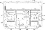
- FIG. 2is a top view of an exemplary chassis for an information handling system with cooling system utilizing two evacuative fans;
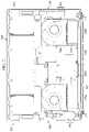
- FIG. 3is a top view of an exemplary chassis for an information handling system with an embodiment of a cooling system utilizing a pressure barrier to divide the chassis into multiple zones, with an evacuative fan in each of two zones and a hyperbaric fan in a third zone;
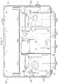
- FIG. 4is a computer simulated image of a temperature profile of a chassis with two evacuative fans
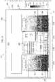
- FIG. 5is a computer simulated image of a temperature profile of a chassis with an embodiment of a cooling system utilizing a pressure barrier to divide the chassis into multiple zones, with an evacuative fan in each of two zones and a hyperbaric fan in a third zone;
- FIG. 6is a diagram of an airflow profile of a chassis with two fans.
- FIG. 7is a computer simulated image of an airflow profile of a chassis with an embodiment of a cooling system utilizing a pressure barrier to divide the chassis into multiple zones, with an evacuative fan in each of two zones and a hyperbaric fan in a third zone.
- a hyphenated form of a reference numeralrefers to a specific instance of an element and the un-hyphenated form of the reference numeral refers to the collective or generic element.
- widget “72-1”refers to an instance of a widget class, which may be referred to collectively as widgets “72” and any one of which may be referred to generically as a widget “72.”
- an information handling systemmay include an instrumentality or aggregate of instrumentalities operable to compute, classify, process, transmit, receive, retrieve, originate, switch, store, display, manifest, detect, record, reproduce, handle, or utilize various forms of information, intelligence, or data for business, scientific, control, entertainment, or other purposes.
- an information handling systemmay be a personal computer, a consumer electronic device, a network storage device, or another suitable device and may vary in size, shape, performance, functionality, and price.
- the information handling systemmay include memory, one or more processing resources such as a central processing unit (CPU) or hardware or software control logic.
- CPUcentral processing unit
- Additional components of the information handling systemmay include one or more storage devices, one or more communications ports for communicating with external devices as well as various input and output (I/O) devices, such as a keyboard, a mouse, and one or more video displays.
- the information handling systemmay also include one or more buses operable to transmit communication between the various hardware components.
- Computer-readable mediamay include an instrumentality or aggregation of instrumentalities that may retain data and/or instructions for a period of time.
- Computer-readable mediamay include, without limitation, storage media such as a direct access storage device (e.g., a hard disk drive or floppy disk), a sequential access storage device (e.g., a tape disk drive), compact disk, CD-ROM, DVD, random access memory (RAM), read-only memory (ROM), electrically erasable programmable read-only memory (EEPROM), and/or flash memory (SSD); as well as communications media such wires, optical fibers, microwaves, radio waves, and other electromagnetic and/or optical carriers; and/or any combination of the foregoing.
- storage mediasuch as a direct access storage device (e.g., a hard disk drive or floppy disk), a sequential access storage device (e.g., a tape disk drive), compact disk, CD-ROM, DVD, random access memory (RAM), read-only memory (ROM), electrically erasable programmable
- FIGS. 1-7wherein like numbers are used to indicate like and corresponding parts.
- FIG. 1illustrates a block diagram depicting selected elements of an embodiment of portable information handling system 100 . It is noted that FIG. 1 is not drawn to scale but is a schematic illustration. In various embodiments, portable information handling system 100 may represent different types of portable devices.
- components of portable information handling system 100may include, but are not limited to, a processor subsystem 120 , which may comprise one or more processors, and a system bus 121 that communicatively couples various system components to processor subsystem 120 including, for example, a memory 130 , an I/O subsystem 140 , local storage resource 150 , and a network interface 160 .
- embedded controller (EC) 180coupled to hyperbaric fan 170 and evacuative fan 172 for managing the temperatures of components in portable information handling system 100 and the temperature of an exterior surface of a chassis containing portable information handling system 100 , as discussed below in greater detail.
- Processor subsystem 120may comprise a system, device, or apparatus operable to interpret and execute program instructions and process data, and may include a microprocessor, microcontroller, digital signal processor (DSP), application specific integrated circuit (ASIC), or another digital or analog circuitry configured to interpret and execute program instructions and process data.
- processor subsystem 120may interpret and execute program instructions and process data stored locally (e.g., in memory 130 ). In the same or alternative embodiments, processor subsystem 120 may interpret and execute program instructions and process data stored remotely (e.g., in a network storage resource).
- System bus 121may represent a variety of suitable types of bus structures, e.g., a memory bus, a peripheral bus, or a local bus using various bus architectures in selected embodiments.
- bus architecturesmay include, but are not limited to, Micro Channel Architecture (MCA) bus, Industry Standard Architecture (ISA) bus, Enhanced ISA (EISA) bus, Peripheral Component Interconnect (PCI) bus, PCI-Express bus, HyperTransport (HT) bus, and Video Electronics Standards Association (VESA) local bus.
- MCAMicro Channel Architecture
- ISAIndustry Standard Architecture
- EISAEnhanced ISA
- PCIPeripheral Component Interconnect
- PCI-ExpressPCI-Express
- HTHyperTransport
- VESAVideo Electronics Standards Association
- Memory 130may comprise a system, device, or apparatus operable to retain and retrieve program instructions and data for a period of time (e.g., computer-readable media).
- Memory 130may comprise random access memory (RAM), electrically erasable programmable read-only memory (EEPROM), a PCMCIA card, flash memory, magnetic storage, opto-magnetic storage or a suitable selection or array of volatile or non-volatile memory that retains data after power is removed.
- RAMrandom access memory
- EEPROMelectrically erasable programmable read-only memory
- PCMCIA cardPCMCIA card
- flash memorymagnetic storage
- opto-magnetic storageor a suitable selection or array of volatile or non-volatile memory that retains data after power is removed.
- FIG. 1memory 130 is shown including an operating system (OS) 132 , which may represent an execution environment for portable information handling system 100 .
- OSoperating system
- Operating system 132may be UNIX or be based on UNIX (e.g., a LINUX variant), one of a number of variants of Microsoft Windows® operating systems, an Apple® MacOS operating system, an embedded operating system, a gaming operating system, or another suitable operating system.
- UNIXe.g., a LINUX variant
- Microsoft Windows® operating systemse.g., Microsoft Windows® Windows®, an Apple® MacOS operating system, an embedded operating system, a gaming operating system, or another suitable operating system.
- Local storage resource 150may comprise computer-readable media (e.g., hard disk drive, floppy disk drive, CD-ROM, and other type of rotating storage media, flash memory, EEPROM, or another type of solid state storage media) and may be generally operable to store instructions and data, and to permit access to stored instructions and data on demand.
- computer-readable mediae.g., hard disk drive, floppy disk drive, CD-ROM, and other type of rotating storage media, flash memory, EEPROM, or another type of solid state storage media
- Network interface 160may be a suitable system, apparatus, or device operable to serve as an interface between portable information handling system 100 and a network (not shown).
- Network interface 160may enable portable information handling system 100 to communicate over the network using a suitable transmission protocol or standard.
- network interface 160may be communicatively coupled via the network to a network storage resource (not shown).
- the network coupled to network interface 160may be implemented as, or may be a part of, a storage area network (SAN), personal area network (PAN), local area network (LAN), a metropolitan area network (MAN), a wide area network (WAN), a wireless local area network (WLAN), a virtual private network (VPN), an intranet, the Internet or another appropriate architecture or system that facilitates the communication of signals, data and messages (generally referred to as data).
- SANstorage area network
- PANpersonal area network
- LANlocal area network
- MANmetropolitan area network
- WANwide area network
- WLANwireless local area network
- VPNvirtual private network
- intranetthe Internet or another appropriate architecture or system that facilitates the communication of signals, data and messages (generally referred to as data).
- the network coupled to network interface 160may transmit data using a desired storage or communication protocol, including, but not limited to, Fibre Channel, Frame Relay, Asynchronous Transfer Mode (ATM), Internet protocol (IP), other packet-based protocol, small computer system interface (SCSI), Internet SCSI (iSCSI), Serial Attached SCSI (SAS) or another transport that operates with the SCSI protocol, advanced technology attachment (ATA), serial ATA (SATA), advanced technology attachment packet interface (ATAPI), serial storage architecture (SSA), integrated drive electronics (IDE), or any combination thereof.
- ATMAsynchronous Transfer Mode
- IPInternet protocol
- SCSIInternet SCSI
- iSCSIInternet SCSI
- SASSerial Attached SCSI
- ATAadvanced technology attachment
- SATAserial ATA
- ATAPIadvanced technology attachment packet interface
- SSAserial storage architecture
- IDEintegrated drive electronics
- I/O subsystem 140may comprise a system, device, or apparatus generally operable to receive and transmit data to or from or within portable information handling system 100 .
- I/O subsystem 140may represent, for example, a variety of communication interfaces, graphics interfaces, video interfaces, user input interfaces, and peripheral interfaces.
- I/O subsystem 140may be used to support various peripheral devices, such as a touch panel, a display adapter, a keyboard, an accelerometer, a touch pad, a gyroscope, or a camera, among other examples.
- I/O subsystem 140may support so-called ‘plug and play’ connectivity to external devices, in which the external devices may be added or removed while portable information handling system 100 is operating.
- cooling system 190which includes embedded controller (EC) 180 , hyperbaric fan 170 and one or more evacuative fan(s) 172 .
- EC 180may include EC processor 182 as a second processor included within portable information handling system 100 for certain management tasks, including supporting communication and providing various functionality for cooling portable information handling system 100 .
- EC processor 182may have access to EC memory 184 , which may store EC firmware 186 , representing instructions executable by EC processor 182 for managing operation of hyperbaric fan 170 and one or more evacuative fan(s) 172 .
- Embedded controller 180may execute EC firmware 186 on EC processor 182 even when other components in portable information handling system 100 are inoperable or are powered down.
- EC firmware 186may be in control of EC communication interface(s) 188 , which may represent one or more input/output interfaces or signals that embedded controller 180 can use to communicate with other elements of portable information handling system 100 , such as processor subsystem 120 or I/O subsystem 140 , among others.
- Hyperbaric fan 170may refer to any fan configured for increasing air pressure as a strategy for cooling.
- hyperbaric fan 170may increase static air pressure to cause air to move into restricted areas.
- hyperbaric fan 170may comprise a dual opposed outlet fan. Hyperbaric fan 170 increases air pressure in a particular zone to cause air movement to one or more openings in the zone.
- Evacuative fan 172may refer to any fan configured to generate an airflow. Evacuative fans 172 are typically used to cool components of processor subsystem 120 such as central processing units (CPU) and graphics processing units (GPU), which may generate significant heat due to processing performance. Evacuative fan 172 generates an airflow relative to one or more components of an information handling system in a particular zone to an opening in the zone and decreases air pressure in the zone.
- processor subsystem 120such as central processing units (CPU) and graphics processing units (GPU), which may generate significant heat due to processing performance.
- Evacuative fan 172generates an airflow relative to one or more components of an information handling system in a particular zone to an opening in the zone and decreases air pressure in the zone.
- fan control 148may be responsible for managing operation of hyperbaric fan 170 and evacuative fan 172 to manage the cooling of portable information handling system 100 .
- Fan control 148may communicate with EC memory 184 storing values for a temperature for starting operation of hyperbaric fan 170 or evacuative fan 172 , a fan speed and duration for cooling, and a temperature or time for stopping each of hyperbaric fan 170 and evacuative fan 172 .
- the stored valuesmay include a maximum component operating temperature and a maximum surface temperature, for example.
- fan control 148may be implemented using EC firmware 186 , such as specialized executable instructions for independently starting, operating and stopping hyperbaric fan 170 and evacuative fan 172 based on the values stored in EC memory 184 .
- Embedded controller 180may operate each of evacuative fans 172 and hyperbaric fans 170 independently.
- Portable information handling systems 100may include laptop computers, notebook computers, netbook computers, tablet computers, and 2-in-1 tablet laptop combination computers, among others. Referring to FIGS. 2 and 3 , embodiments of portable information handling system 100 may be assembled in chassis 200 and configured for use as various portable devices.
- chassis 200comprises back panel 202 and front panel 204 defining a width of chassis 200 and side panels 206 defining a length of chassis 200 .
- Back panel 202comprises openings 218 generally configured to facilitate air entering and exiting chassis 200 .
- Side panels 206comprise openings 216 associated with USB ports, HDMI ports, cable attachment points or other I/O components such that air may enter and exit chassis 200 .
- Back panel 202 , front panel 204 and side panels 206define a depth of chassis 200 between a bottom cover (not visible in FIG. 2 or 3 ) and a user surface (not shown).
- components of processor subsystem 120 , memory 130 , I/O subsystem 140 , local storage resource 150 , network interface 160 and cooling system 190may be positioned to allow for a more compact design.
- Cooling a portable deviceinvolves cooling components of portable information handling system 100 and cooling chassis 200 .
- Certain components of portable information handling system 100can generate heat at a rate that can cause the component operating temperature (T JUNCTION ) to exceed a maximum operating temperature. If the component operating temperature (T JUNCTION ) exceeds the maximum operating temperature, the component may have reduced performance or fail.
- Componentssuch as processors may be thermally coupled to fin stacks 214 that have a surface area configured for improved heat transfer to air.
- evacuative fans 172 amay be located proximate to fin stacks 214 a and oriented for directing airflow across fin stacks 214 a to openings 218 a and 218 d.
- chassis 200In addition to the heat generated by individual components of portable information handling system 100 , the compact design of chassis 200 and the configuration of portable information handling system 100 within chassis 200 may cause heat to build up in chassis 200 . Ideally, heat exits chassis 200 via openings 218 in back panel 202 or openings 216 in side panels 206 . However, as more components are contained in chassis 200 , airflow may be more restricted, causing heat to be transferred to the environment through one or more of the bottom cover or top surface. If heat is transferred through the bottom cover and the surface temperature (T SKIN ) exceeds a maximum or limiting temperature, the heat could cause discomfort or injury to a user. Thus, the surface temperature T SKIN for a bottom cover of chassis 200 may be limited. A common limitation is for the surface temperature T SKIN for the bottom cover to not exceed 55 degrees Celsius (C).
- Cdegrees Celsius
- embodiments of a cooling system for chassis 200 containing portable information handling system 100are disclosed.
- embodiments of a cooling system for chassis 200 and portable information handling system 100comprise thermal barrier 224 dividing chassis 200 into a plurality of zones, with a combination of evacuative fan(s) 172 to cool one or more components and hyperbaric fan 170 to cool chassis 200 .
- Chassis 200may be divided into a plurality of zones (Zones 1 , 2 and 3 are depicted in FIG. 3 ) by pressure barrier 224 .
- the material used to form pressure barrier 224 and the layout of pressure barrier 224 in chassis 200may depend on the size or dimensions of chassis 200 and the number, size, desired operating temperature, maximum operating temperature, or other characteristics of components in portable information handling system 100 .
- pressure barrier 224comprises material to allow a pressure differential between two adjacent zones.
- pressure barrier 224may be formed with material to thermally isolate components, acoustically dampen noise in chassis 200 , or provide electromagnetic insulation of one or more components in portable information handling system 100 .
- pressure barrier 224 formed with electromagnetic insulationforms a Faraday cage (not shown) around one or more components of portable information handling system 100 .
- FIG. 3depicts Zones 1 and 3 with evacuative fans 172 b located proximate to fin stacks 214 b and oriented for directing airflow across fin stacks 214 b to openings 218 a and 218 d .
- evacuative fans 172 b and fin stacks 214 bare smaller than evacuative fans 172 a and fin stacks 214 a , respectively, discussed in greater detail below.
- Table 1depicts representative measurements and simulated outcomes for comparing a first cooling system associated with chassis 200 having only evacuative fans 172 a and a second cooling system associated with portable information handling system 100 utilizing pressure barrier 224 to divide chassis 200 into multiple zones and using evacuative fans 172 b to cool components and one hyperbaric fan 170 to cool a bottom cover of chassis 200 .
- a CPUmay operate at 25 W of power with a component operating temperature (CPU T JUNCTION ) at 68 C, which is below the maximum component operating temperature of 100 C and a GPU may operate at 60 W of power with a component operating temperature (GPU T JUNCTION ) at 77 C, which is below the maximum component operating temperature of 89 C.
- a bottom cover temperatureT SKIN ) reaches the maximum temperature of 55 C.
- the CPUmay operate at 35 W of power with a component operating temperature (CPU T JUNCTION ) at 75 C and may the GPU may operate at 65 W of power with a component operating temperature (GPU T JUNCTION ) at 86 C, but the bottom cover temperature (T SKIN ) reaches only 53 C.
- the CPU powermay be increased by 10 Watts and the GPU power may be increased by 5 W for a total 15 W increase without exceeding any maximum temperatures.
- Embodiments of portable information handling system 100utilize smart cooling strategies. As mentioned above, evacuative fans 172 b and fin stacks 214 b may be smaller than evacuative fans 172 a and fin stacks 214 a but are still able to cool components of portable information handling system 100 . Furthermore, cooling system 190 cools components in portable information handling system 100 and cools a bottom cover of chassis 200 . Table 2 depicts representative measurements and simulated outcomes comparing a first cooling system such as depicted in FIG. 2 and embodiments of cooling system 190 such as depicted in FIG. 3 .
- the total foot print areamay be 5% less and the fin stack size may be 11% less. Even though the component operating temperatures (CPU T JUNCTION and GPU T JUNCTION ) may be hotter, they are still below the maximum temperature and the surface temperature (T SKIN ) of the bottom cover may be reduced by 5 C.
- portable information handling system 100 in chassis 200may use cooling system 190 with an overall size that is smaller and generates less airflow but can cool components and a bottom cover of chassis 200 more effectively.
- FIGS. 4-7computer simulated images of temperature and airflow profiles illustrate the effectiveness of cooling system 170 implemented in chassis 200 .
- FIG. 4depicts a simulated image 400 of a temperature profile of bottom cover 410 for chassis 200 utilizing the cooling system depicted in FIG. 2 .
- Simulated image 400illustrates large areas 420 (associated with large evacuative fans 172 a ) with cooler temperatures, but bottom cover 410 reaches the maximum surface temperature (T SKIN ) of 55 C.
- T SKINmaximum surface temperature
- FIG. 5depicts a simulated image 500 of a temperature profile of bottom cover 410 for chassis 200 utilizing cooling system 190 depicted in FIG. 3 .
- Simulated image 500illustrates smaller areas 520 (associated with smaller evacuative fans 172 b ) with cooler temperatures and area 522 associated with hyperbaric fan 170 .
- bottom cover 410reaches a surface temperature (T SKIN ) of 50 C.
- openings 218 b and 218 cindicate a larger transfer of heat from chassis 200 by hyperbaric fan 170 such that, even though openings 218 a and 218 d may be smaller than openings 218 a and 218 d in FIG. 4 , significant heat is discharged from chassis 200 to cool bottom cover 410 .
- FIG. 6depicts a simulated image 600 of an airflow profile for chassis 200 utilizing the cooling system depicted in FIG. 2 .
- Simulated image 600illustrates large areas 602 (associated with large evacuative fans 172 a ) with higher airflow speeds, but area 606 indicates little or no airflow speed.
- simulated image 600depicts airflow speeds relative to openings 218 b and 218 c on back panel 202 as well as relative to side panels 206 , indicating that heat in chassis 200 may circulate through chassis 200 before exiting.
- FIG. 7depicts a simulated image 700 of an airflow profile for chassis 200 utilizing cooling system 190 depicted in FIG. 3 .
- Simulated image 700illustrates smaller areas 702 (associated with Zones 1 and 3 having smaller evacuative fans 172 b ) with higher airflow speeds.
- Simulated image 700further depicts area 706 (associated with Zone 2 having hyperbaric fan 170 ) with some airflow, indicating that a pressure barrier 224 isolating Zone 2 and an increase in pressure by hyperbaric fan 170 may provide enough airflow through chassis 200 to cool bottom cover 410 .
- simulated image 600depicts minimal airflow speeds relative to side panels 206 , indicating that openings 216 or additional openings 218 may not be required to cool portable information handling system 100 .
- the systems and methods described hereinmay cool a portable information handling system by dividing the chassis into zones and positioning an evacuative fan in a first zone to cool components and positioning a hyperbaric fan in a second zone to increase air pressure to cool the chassis.
Landscapes
- Engineering & Computer Science (AREA)
- Theoretical Computer Science (AREA)
- Physics & Mathematics (AREA)
- Computer Hardware Design (AREA)
- General Engineering & Computer Science (AREA)
- Microelectronics & Electronic Packaging (AREA)
- Human Computer Interaction (AREA)
- General Physics & Mathematics (AREA)
- Thermal Sciences (AREA)
- Cooling Or The Like Of Electrical Apparatus (AREA)
Abstract
Description
| One hyperbaric fan and | |||||
| two evacuative fans plus | |||||
| Limit | Two fans | thermal barrier | Difference | ||
| CPU + GPU | N/A | 85 | W | 100 | W | 15 W increase |
| Power | ||||||
| CPU Power | N/A | 25 | W | 35 | W | 10 W increase |
| GPU Power | N/A | 60 | W | 65 | W | 5 W increase |
| Bottom cover | 55 C. | 55 | C. | 53 | C. | 2 C. decrease |
| temperature (TSKIN) |
| 100 | 68 | 75 | 7 C. increase | |
| GPU TJUNCTION | 89 | 77 | 86 | 9 C. increase |
| System with pressure | |||||
| System with | barrier, two evacuative fans | ||||
| Limit | two fans | and one hyperbaric fan | Difference | ||
| Total fan foot | N/A | 15488 | mm2 | 14668 | mm2 | 5% less |
| print area |
| Fin stack size | N/A | 35 × 88 (each) | 35 × 78 (each) | 11% less |
| CPU Power | N/A | 25 | W | 25 | W | None |
| GPU Power | N/A | 60 | W | 60 | W | None |
| TSKIN | 55 C. | 55 | C. | 50 | C. | 5 C. |
| CPU T |
| JUNCTION | 100 | 68 | 69 | 1 C. hotter |
| GPU TJUNCTION | 89 | 77 | 79 | 2 C. hotter |
Claims (18)
Priority Applications (1)
| Application Number | Priority Date | Filing Date | Title |
|---|---|---|---|
| US16/777,431US11507156B2 (en) | 2020-01-30 | 2020-01-30 | Cooling system with hyperbaric fan and evacuative fan |
Applications Claiming Priority (1)
| Application Number | Priority Date | Filing Date | Title |
|---|---|---|---|
| US16/777,431US11507156B2 (en) | 2020-01-30 | 2020-01-30 | Cooling system with hyperbaric fan and evacuative fan |
Publications (2)
| Publication Number | Publication Date |
|---|---|
| US20210240239A1 US20210240239A1 (en) | 2021-08-05 |
| US11507156B2true US11507156B2 (en) | 2022-11-22 |
Family
ID=77061998
Family Applications (1)
| Application Number | Title | Priority Date | Filing Date |
|---|---|---|---|
| US16/777,431Active2041-03-19US11507156B2 (en) | 2020-01-30 | 2020-01-30 | Cooling system with hyperbaric fan and evacuative fan |
Country Status (1)
| Country | Link |
|---|---|
| US (1) | US11507156B2 (en) |
Cited By (2)
| Publication number | Priority date | Publication date | Assignee | Title |
|---|---|---|---|---|
| EP4468113A1 (en)* | 2023-05-23 | 2024-11-27 | Intel Corporation | Removable fan cartridges for electronic devices |
| US12396124B2 (en) | 2020-12-23 | 2025-08-19 | Intel Corporation | Fan module interconnect apparatus for electronic devices |
Families Citing this family (5)
| Publication number | Priority date | Publication date | Assignee | Title |
|---|---|---|---|---|
| CN111343811B (en)* | 2020-03-05 | 2021-02-23 | 武汉华星光电半导体显示技术有限公司 | Heat dissipation system and shell of foldable mobile terminal and foldable mobile terminal |
| US11435795B1 (en)* | 2021-04-14 | 2022-09-06 | Dell Products L.P. | EMI shield system and method for hyperbaric fan cooling systems |
| US11914437B2 (en)* | 2021-04-28 | 2024-02-27 | Dell Products L.P. | High-performance computing cooling system |
| US11927996B2 (en)* | 2021-04-28 | 2024-03-12 | Dell Products L.P. | High-performance computing cooling system |
| US11958403B2 (en)* | 2022-05-23 | 2024-04-16 | Caterpillar Inc. | Rooftop structure for semi-autonomous CTL |
Citations (16)
| Publication number | Priority date | Publication date | Assignee | Title |
|---|---|---|---|---|
| US5694294A (en)* | 1995-01-27 | 1997-12-02 | Hitachi, Ltd. | Portable computer with fan moving air from a first space created between a keyboard and a first circuit board and a second space created between the first circuit board and a second circuit board |
| US5828034A (en)* | 1997-01-03 | 1998-10-27 | Chang; Wen-Lung | Warmed computer input peripherals for keeping a computer user's hand and fingers warm and comfortable |
| US6255622B1 (en)* | 1999-10-27 | 2001-07-03 | Hewlett-Packard Company | Electronic device having external surface thermal feedback |
| US20030161102A1 (en)* | 2002-03-08 | 2003-08-28 | Harrison Lee | Cooler of notebook personal computer and fabrication method thereof |
| US6744631B1 (en)* | 2002-11-15 | 2004-06-01 | Compal Electronics, Inc. | Heat dissipating device |
| US20050049729A1 (en)* | 2003-08-15 | 2005-03-03 | Michael Culbert | Methods and apparatuses for operating a data processing system |
| US6909602B2 (en)* | 2002-05-24 | 2005-06-21 | International Business Machines Corporation | Temperature-controlled user interface |
| US20050152112A1 (en)* | 2004-01-08 | 2005-07-14 | Apple Computer Inc. | Apparatus for air cooling of an electronic device |
| US6934267B1 (en)* | 1999-10-13 | 2005-08-23 | Telefonaktiebolaget L M Ericsson (Publ) | Time slot allocation control based on temperature in a radio transceiver |
| US20050288886A1 (en)* | 2004-06-28 | 2005-12-29 | Therien Guy M | Extended thermal management |
| US20120069514A1 (en)* | 2010-09-20 | 2012-03-22 | Ross Peter G | System with air flow under data storage devices |
| US20120075992A1 (en)* | 2010-09-24 | 2012-03-29 | Qualcomm, Incorporated | Methods and apparatus for touch temperature management based on power dissipation history |
| US20160095250A1 (en)* | 2014-09-26 | 2016-03-31 | Dell Products L.P. | Airflow control system |
| US20170079160A1 (en)* | 2014-12-18 | 2017-03-16 | Dell Products L.P. | Regulation of airflow and performance in information handling systems after fan failure |
| US20190069441A1 (en)* | 2017-08-28 | 2019-02-28 | Dmytro KHACHATUROV | System and method for forced air cooling of electrical device |
| US10851800B2 (en)* | 2019-04-25 | 2020-12-01 | Dell Products, Lp | Blower system with dual opposite outlets and fan diameter approaching to blower housing dimension for information handling systems |
- 2020
- 2020-01-30USUS16/777,431patent/US11507156B2/enactiveActive
Patent Citations (18)
| Publication number | Priority date | Publication date | Assignee | Title |
|---|---|---|---|---|
| US5694294A (en)* | 1995-01-27 | 1997-12-02 | Hitachi, Ltd. | Portable computer with fan moving air from a first space created between a keyboard and a first circuit board and a second space created between the first circuit board and a second circuit board |
| US5828034A (en)* | 1997-01-03 | 1998-10-27 | Chang; Wen-Lung | Warmed computer input peripherals for keeping a computer user's hand and fingers warm and comfortable |
| US6934267B1 (en)* | 1999-10-13 | 2005-08-23 | Telefonaktiebolaget L M Ericsson (Publ) | Time slot allocation control based on temperature in a radio transceiver |
| US6255622B1 (en)* | 1999-10-27 | 2001-07-03 | Hewlett-Packard Company | Electronic device having external surface thermal feedback |
| US20030161102A1 (en)* | 2002-03-08 | 2003-08-28 | Harrison Lee | Cooler of notebook personal computer and fabrication method thereof |
| US6909602B2 (en)* | 2002-05-24 | 2005-06-21 | International Business Machines Corporation | Temperature-controlled user interface |
| US6744631B1 (en)* | 2002-11-15 | 2004-06-01 | Compal Electronics, Inc. | Heat dissipating device |
| US20050049729A1 (en)* | 2003-08-15 | 2005-03-03 | Michael Culbert | Methods and apparatuses for operating a data processing system |
| US20050152112A1 (en)* | 2004-01-08 | 2005-07-14 | Apple Computer Inc. | Apparatus for air cooling of an electronic device |
| US20050288886A1 (en)* | 2004-06-28 | 2005-12-29 | Therien Guy M | Extended thermal management |
| US20120069514A1 (en)* | 2010-09-20 | 2012-03-22 | Ross Peter G | System with air flow under data storage devices |
| US20120075992A1 (en)* | 2010-09-24 | 2012-03-29 | Qualcomm, Incorporated | Methods and apparatus for touch temperature management based on power dissipation history |
| US20160095250A1 (en)* | 2014-09-26 | 2016-03-31 | Dell Products L.P. | Airflow control system |
| US9392726B2 (en)* | 2014-09-26 | 2016-07-12 | Dell Products L.P. | Airflow control system |
| US20170079160A1 (en)* | 2014-12-18 | 2017-03-16 | Dell Products L.P. | Regulation of airflow and performance in information handling systems after fan failure |
| US9743552B2 (en)* | 2014-12-18 | 2017-08-22 | Dell Products L.P. | Regulation of airflow and performance in information handling systems after fan failure |
| US20190069441A1 (en)* | 2017-08-28 | 2019-02-28 | Dmytro KHACHATUROV | System and method for forced air cooling of electrical device |
| US10851800B2 (en)* | 2019-04-25 | 2020-12-01 | Dell Products, Lp | Blower system with dual opposite outlets and fan diameter approaching to blower housing dimension for information handling systems |
Cited By (3)
| Publication number | Priority date | Publication date | Assignee | Title |
|---|---|---|---|---|
| US12396124B2 (en) | 2020-12-23 | 2025-08-19 | Intel Corporation | Fan module interconnect apparatus for electronic devices |
| EP4468113A1 (en)* | 2023-05-23 | 2024-11-27 | Intel Corporation | Removable fan cartridges for electronic devices |
| US12396125B2 (en) | 2023-05-23 | 2025-08-19 | Intel Corporation | Removable fan cartridges for electronic devices |
Also Published As
| Publication number | Publication date |
|---|---|
| US20210240239A1 (en) | 2021-08-05 |
Similar Documents
| Publication | Publication Date | Title |
|---|---|---|
| US11507156B2 (en) | Cooling system with hyperbaric fan and evacuative fan | |
| US9743552B2 (en) | Regulation of airflow and performance in information handling systems after fan failure | |
| CN1983114B (en) | Ventilated computer chassis | |
| US11243584B2 (en) | Cooling system with acoustic noise control in an information handling system | |
| US20140118926A1 (en) | Rotatable Fan Array Rotated Based on Computer Process Execution for Personal Computer | |
| US9681577B2 (en) | System and method for improving fan life in an information handling system | |
| US20160034007A1 (en) | Triangular System for Modifiable Thermal Control | |
| JP6038222B1 (en) | Heat dissipation structure, discharge method, heat dissipation system, and information processing apparatus | |
| US11592882B2 (en) | Variable fin stack | |
| US11599168B2 (en) | Extended thermal battery for cooling portable devices | |
| US20240231445A9 (en) | Air shroud having built in air movers for enhanced cooling | |
| US20170329651A1 (en) | Systems and methods for load balancing based on thermal parameters | |
| US10571981B2 (en) | System and method of transferring energy in information handling system | |
| US11432413B2 (en) | Multi-layer vent for increased airflow and EMI shielding in an information handling system | |
| US20240040738A1 (en) | Codesigned air shroud | |
| US12130676B2 (en) | Method of fan control in an information handling system using a pseudo temperature sensor | |
| CN114673670A (en) | Information handling system with column fan package | |
| US20240069609A1 (en) | Support device for an expansion card of an information handling system | |
| US12016159B2 (en) | Cooling system with a porous foam heat exchanger and a positive displacement air pump | |
| US11917792B2 (en) | Dual opposed outlet fan with two impellers | |
| KR102425505B1 (en) | Ambient temperature aware VM allocation method and apparatus for virtualized heterogeneous data centers | |
| CN104217743B (en) | Electronic device and frame structure thereof | |
| US20250048598A1 (en) | System airflow bypassing restricted rear i/o panel via power supply unit region | |
| US12207443B2 (en) | Low-noise heat exchanger | |
| US11508414B2 (en) | Storage module with reduced airflow impedance and improved storage device dynamics performance |
Legal Events
| Date | Code | Title | Description |
|---|---|---|---|
| AS | Assignment | Owner name:DELL PRODUCTS L.P., TEXAS Free format text:ASSIGNMENT OF ASSIGNORS INTEREST;ASSIGNORS:HE, QINGHONG;NORTH, TRAVIS CHRISTIAN;MCKITTRICK, ALLEN B.;REEL/FRAME:051676/0415 Effective date:20200129 | |
| FEPP | Fee payment procedure | Free format text:ENTITY STATUS SET TO UNDISCOUNTED (ORIGINAL EVENT CODE: BIG.); ENTITY STATUS OF PATENT OWNER: LARGE ENTITY | |
| STPP | Information on status: patent application and granting procedure in general | Free format text:APPLICATION DISPATCHED FROM PREEXAM, NOT YET DOCKETED | |
| AS | Assignment | Owner name:THE BANK OF NEW YORK MELLON TRUST COMPANY, N.A., AS COLLATERAL AGENT, TEXAS Free format text:PATENT SECURITY AGREEMENT (NOTES);ASSIGNORS:DELL PRODUCTS L.P.;EMC IP HOLDING COMPANY LLC;REEL/FRAME:052216/0758 Effective date:20200324 | |
| AS | Assignment | Owner name:CREDIT SUISSE AG, CAYMAN ISLANDS BRANCH, NORTH CAROLINA Free format text:SECURITY AGREEMENT;ASSIGNORS:DELL PRODUCTS L.P.;EMC IP HOLDING COMPANY LLC;REEL/FRAME:052243/0773 Effective date:20200326 | |
| AS | Assignment | Owner name:THE BANK OF NEW YORK MELLON TRUST COMPANY, N.A., TEXAS Free format text:SECURITY AGREEMENT;ASSIGNORS:CREDANT TECHNOLOGIES INC.;DELL INTERNATIONAL L.L.C.;DELL MARKETING L.P.;AND OTHERS;REEL/FRAME:053546/0001 Effective date:20200409 | |
| AS | Assignment | Owner name:THE BANK OF NEW YORK MELLON TRUST COMPANY, N.A., AS COLLATERAL AGENT, TEXAS Free format text:SECURITY INTEREST;ASSIGNORS:DELL PRODUCTS L.P.;EMC CORPORATION;EMC IP HOLDING COMPANY LLC;REEL/FRAME:053311/0169 Effective date:20200603 | |
| STPP | Information on status: patent application and granting procedure in general | Free format text:DOCKETED NEW CASE - READY FOR EXAMINATION | |
| AS | Assignment | Owner name:EMC IP HOLDING COMPANY LLC, TEXAS Free format text:RELEASE OF SECURITY INTEREST AF REEL 052243 FRAME 0773;ASSIGNOR:CREDIT SUISSE AG, CAYMAN ISLANDS BRANCH;REEL/FRAME:058001/0152 Effective date:20211101 Owner name:DELL PRODUCTS L.P., TEXAS Free format text:RELEASE OF SECURITY INTEREST AF REEL 052243 FRAME 0773;ASSIGNOR:CREDIT SUISSE AG, CAYMAN ISLANDS BRANCH;REEL/FRAME:058001/0152 Effective date:20211101 | |
| STPP | Information on status: patent application and granting procedure in general | Free format text:NON FINAL ACTION MAILED | |
| AS | Assignment | Owner name:EMC IP HOLDING COMPANY LLC, TEXAS Free format text:RELEASE OF SECURITY INTEREST IN PATENTS PREVIOUSLY RECORDED AT REEL/FRAME (053311/0169);ASSIGNOR:THE BANK OF NEW YORK MELLON TRUST COMPANY, N.A., AS NOTES COLLATERAL AGENT;REEL/FRAME:060438/0742 Effective date:20220329 Owner name:EMC CORPORATION, MASSACHUSETTS Free format text:RELEASE OF SECURITY INTEREST IN PATENTS PREVIOUSLY RECORDED AT REEL/FRAME (053311/0169);ASSIGNOR:THE BANK OF NEW YORK MELLON TRUST COMPANY, N.A., AS NOTES COLLATERAL AGENT;REEL/FRAME:060438/0742 Effective date:20220329 Owner name:DELL PRODUCTS L.P., TEXAS Free format text:RELEASE OF SECURITY INTEREST IN PATENTS PREVIOUSLY RECORDED AT REEL/FRAME (053311/0169);ASSIGNOR:THE BANK OF NEW YORK MELLON TRUST COMPANY, N.A., AS NOTES COLLATERAL AGENT;REEL/FRAME:060438/0742 Effective date:20220329 Owner name:EMC IP HOLDING COMPANY LLC, TEXAS Free format text:RELEASE OF SECURITY INTEREST IN PATENTS PREVIOUSLY RECORDED AT REEL/FRAME (052216/0758);ASSIGNOR:THE BANK OF NEW YORK MELLON TRUST COMPANY, N.A., AS NOTES COLLATERAL AGENT;REEL/FRAME:060438/0680 Effective date:20220329 Owner name:DELL PRODUCTS L.P., TEXAS Free format text:RELEASE OF SECURITY INTEREST IN PATENTS PREVIOUSLY RECORDED AT REEL/FRAME (052216/0758);ASSIGNOR:THE BANK OF NEW YORK MELLON TRUST COMPANY, N.A., AS NOTES COLLATERAL AGENT;REEL/FRAME:060438/0680 Effective date:20220329 Owner name:DELL MARKETING L.P. (ON BEHALF OF ITSELF AND AS SUCCESSOR-IN-INTEREST TO CREDANT TECHNOLOGIES, INC.), TEXAS Free format text:RELEASE OF SECURITY INTEREST IN PATENTS PREVIOUSLY RECORDED AT REEL/FRAME (053546/0001);ASSIGNOR:THE BANK OF NEW YORK MELLON TRUST COMPANY, N.A., AS NOTES COLLATERAL AGENT;REEL/FRAME:071642/0001 Effective date:20220329 Owner name:DELL INTERNATIONAL L.L.C., TEXAS Free format text:RELEASE OF SECURITY INTEREST IN PATENTS PREVIOUSLY RECORDED AT REEL/FRAME (053546/0001);ASSIGNOR:THE BANK OF NEW YORK MELLON TRUST COMPANY, N.A., AS NOTES COLLATERAL AGENT;REEL/FRAME:071642/0001 Effective date:20220329 Owner name:DELL PRODUCTS L.P., TEXAS Free format text:RELEASE OF SECURITY INTEREST IN PATENTS PREVIOUSLY RECORDED AT REEL/FRAME (053546/0001);ASSIGNOR:THE BANK OF NEW YORK MELLON TRUST COMPANY, N.A., AS NOTES COLLATERAL AGENT;REEL/FRAME:071642/0001 Effective date:20220329 Owner name:DELL USA L.P., TEXAS Free format text:RELEASE OF SECURITY INTEREST IN PATENTS PREVIOUSLY RECORDED AT REEL/FRAME (053546/0001);ASSIGNOR:THE BANK OF NEW YORK MELLON TRUST COMPANY, N.A., AS NOTES COLLATERAL AGENT;REEL/FRAME:071642/0001 Effective date:20220329 Owner name:EMC CORPORATION, MASSACHUSETTS Free format text:RELEASE OF SECURITY INTEREST IN PATENTS PREVIOUSLY RECORDED AT REEL/FRAME (053546/0001);ASSIGNOR:THE BANK OF NEW YORK MELLON TRUST COMPANY, N.A., AS NOTES COLLATERAL AGENT;REEL/FRAME:071642/0001 Effective date:20220329 Owner name:DELL MARKETING CORPORATION (SUCCESSOR-IN-INTEREST TO FORCE10 NETWORKS, INC. AND WYSE TECHNOLOGY L.L.C.), TEXAS Free format text:RELEASE OF SECURITY INTEREST IN PATENTS PREVIOUSLY RECORDED AT REEL/FRAME (053546/0001);ASSIGNOR:THE BANK OF NEW YORK MELLON TRUST COMPANY, N.A., AS NOTES COLLATERAL AGENT;REEL/FRAME:071642/0001 Effective date:20220329 Owner name:EMC IP HOLDING COMPANY LLC, TEXAS Free format text:RELEASE OF SECURITY INTEREST IN PATENTS PREVIOUSLY RECORDED AT REEL/FRAME (053546/0001);ASSIGNOR:THE BANK OF NEW YORK MELLON TRUST COMPANY, N.A., AS NOTES COLLATERAL AGENT;REEL/FRAME:071642/0001 Effective date:20220329 | |
| STPP | Information on status: patent application and granting procedure in general | Free format text:RESPONSE TO NON-FINAL OFFICE ACTION ENTERED AND FORWARDED TO EXAMINER | |
| STPP | Information on status: patent application and granting procedure in general | Free format text:NOTICE OF ALLOWANCE MAILED -- APPLICATION RECEIVED IN OFFICE OF PUBLICATIONS | |
| STCF | Information on status: patent grant | Free format text:PATENTED CASE |