US11506235B2 - Elements and a locking device for an assembled product - Google Patents
Elements and a locking device for an assembled productDownload PDFInfo
- Publication number
- US11506235B2 US11506235B2US15/978,630US201815978630AUS11506235B2US 11506235 B2US11506235 B2US 11506235B2US 201815978630 AUS201815978630 AUS 201815978630AUS 11506235 B2US11506235 B2US 11506235B2
- Authority
- US
- United States
- Prior art keywords
- groove
- cylindrical shaped
- flexible tongue
- tongue
- flexible
- Prior art date
- Legal status (The legal status is an assumption and is not a legal conclusion. Google has not performed a legal analysis and makes no representation as to the accuracy of the status listed.)
- Active, expires
Links
Images


Classifications
- F—MECHANICAL ENGINEERING; LIGHTING; HEATING; WEAPONS; BLASTING
- F16—ENGINEERING ELEMENTS AND UNITS; GENERAL MEASURES FOR PRODUCING AND MAINTAINING EFFECTIVE FUNCTIONING OF MACHINES OR INSTALLATIONS; THERMAL INSULATION IN GENERAL
- F16B—DEVICES FOR FASTENING OR SECURING CONSTRUCTIONAL ELEMENTS OR MACHINE PARTS TOGETHER, e.g. NAILS, BOLTS, CIRCLIPS, CLAMPS, CLIPS OR WEDGES; JOINTS OR JOINTING
- F16B12/00—Jointing of furniture or the like, e.g. hidden from exterior
- F16B12/10—Jointing of furniture or the like, e.g. hidden from exterior using pegs, bolts, tenons, clamps, clips, or the like
- F16B12/12—Jointing of furniture or the like, e.g. hidden from exterior using pegs, bolts, tenons, clamps, clips, or the like for non-metal furniture parts, e.g. made of wood, of plastics
- F16B12/14—Jointing of furniture or the like, e.g. hidden from exterior using pegs, bolts, tenons, clamps, clips, or the like for non-metal furniture parts, e.g. made of wood, of plastics using threaded bolts or screws
- F—MECHANICAL ENGINEERING; LIGHTING; HEATING; WEAPONS; BLASTING
- F16—ENGINEERING ELEMENTS AND UNITS; GENERAL MEASURES FOR PRODUCING AND MAINTAINING EFFECTIVE FUNCTIONING OF MACHINES OR INSTALLATIONS; THERMAL INSULATION IN GENERAL
- F16B—DEVICES FOR FASTENING OR SECURING CONSTRUCTIONAL ELEMENTS OR MACHINE PARTS TOGETHER, e.g. NAILS, BOLTS, CIRCLIPS, CLAMPS, CLIPS OR WEDGES; JOINTS OR JOINTING
- F16B12/00—Jointing of furniture or the like, e.g. hidden from exterior
- F16B12/10—Jointing of furniture or the like, e.g. hidden from exterior using pegs, bolts, tenons, clamps, clips, or the like
- F16B12/12—Jointing of furniture or the like, e.g. hidden from exterior using pegs, bolts, tenons, clamps, clips, or the like for non-metal furniture parts, e.g. made of wood, of plastics
- F16B12/20—Jointing of furniture or the like, e.g. hidden from exterior using pegs, bolts, tenons, clamps, clips, or the like for non-metal furniture parts, e.g. made of wood, of plastics using clamps, clips, wedges, sliding bolts, or the like
- F16B12/2009—Jointing of furniture or the like, e.g. hidden from exterior using pegs, bolts, tenons, clamps, clips, or the like for non-metal furniture parts, e.g. made of wood, of plastics using clamps, clips, wedges, sliding bolts, or the like actuated by rotary motion
- F16B12/2054—Jointing of furniture or the like, e.g. hidden from exterior using pegs, bolts, tenons, clamps, clips, or the like for non-metal furniture parts, e.g. made of wood, of plastics using clamps, clips, wedges, sliding bolts, or the like actuated by rotary motion with engaging screw threads as securing means for limiting movement
- F16B12/2063—Jointing of furniture or the like, e.g. hidden from exterior using pegs, bolts, tenons, clamps, clips, or the like for non-metal furniture parts, e.g. made of wood, of plastics using clamps, clips, wedges, sliding bolts, or the like actuated by rotary motion with engaging screw threads as securing means for limiting movement with engaging screw threads as tightening means
- F—MECHANICAL ENGINEERING; LIGHTING; HEATING; WEAPONS; BLASTING
- F16—ENGINEERING ELEMENTS AND UNITS; GENERAL MEASURES FOR PRODUCING AND MAINTAINING EFFECTIVE FUNCTIONING OF MACHINES OR INSTALLATIONS; THERMAL INSULATION IN GENERAL
- F16B—DEVICES FOR FASTENING OR SECURING CONSTRUCTIONAL ELEMENTS OR MACHINE PARTS TOGETHER, e.g. NAILS, BOLTS, CIRCLIPS, CLAMPS, CLIPS OR WEDGES; JOINTS OR JOINTING
- F16B12/00—Jointing of furniture or the like, e.g. hidden from exterior
- F16B12/10—Jointing of furniture or the like, e.g. hidden from exterior using pegs, bolts, tenons, clamps, clips, or the like
- F16B12/12—Jointing of furniture or the like, e.g. hidden from exterior using pegs, bolts, tenons, clamps, clips, or the like for non-metal furniture parts, e.g. made of wood, of plastics
- F16B12/22—Jointing of furniture or the like, e.g. hidden from exterior using pegs, bolts, tenons, clamps, clips, or the like for non-metal furniture parts, e.g. made of wood, of plastics using keyhole-shaped slots and pins
- F—MECHANICAL ENGINEERING; LIGHTING; HEATING; WEAPONS; BLASTING
- F16—ENGINEERING ELEMENTS AND UNITS; GENERAL MEASURES FOR PRODUCING AND MAINTAINING EFFECTIVE FUNCTIONING OF MACHINES OR INSTALLATIONS; THERMAL INSULATION IN GENERAL
- F16B—DEVICES FOR FASTENING OR SECURING CONSTRUCTIONAL ELEMENTS OR MACHINE PARTS TOGETHER, e.g. NAILS, BOLTS, CIRCLIPS, CLAMPS, CLIPS OR WEDGES; JOINTS OR JOINTING
- F16B12/00—Jointing of furniture or the like, e.g. hidden from exterior
- F16B12/10—Jointing of furniture or the like, e.g. hidden from exterior using pegs, bolts, tenons, clamps, clips, or the like
- F16B12/12—Jointing of furniture or the like, e.g. hidden from exterior using pegs, bolts, tenons, clamps, clips, or the like for non-metal furniture parts, e.g. made of wood, of plastics
- F16B12/24—Jointing of furniture or the like, e.g. hidden from exterior using pegs, bolts, tenons, clamps, clips, or the like for non-metal furniture parts, e.g. made of wood, of plastics using separate pins, dowels, or the like
- F—MECHANICAL ENGINEERING; LIGHTING; HEATING; WEAPONS; BLASTING
- F16—ENGINEERING ELEMENTS AND UNITS; GENERAL MEASURES FOR PRODUCING AND MAINTAINING EFFECTIVE FUNCTIONING OF MACHINES OR INSTALLATIONS; THERMAL INSULATION IN GENERAL
- F16B—DEVICES FOR FASTENING OR SECURING CONSTRUCTIONAL ELEMENTS OR MACHINE PARTS TOGETHER, e.g. NAILS, BOLTS, CIRCLIPS, CLAMPS, CLIPS OR WEDGES; JOINTS OR JOINTING
- F16B12/00—Jointing of furniture or the like, e.g. hidden from exterior
- F16B12/10—Jointing of furniture or the like, e.g. hidden from exterior using pegs, bolts, tenons, clamps, clips, or the like
- F16B12/12—Jointing of furniture or the like, e.g. hidden from exterior using pegs, bolts, tenons, clamps, clips, or the like for non-metal furniture parts, e.g. made of wood, of plastics
- F16B12/26—Jointing of furniture or the like, e.g. hidden from exterior using pegs, bolts, tenons, clamps, clips, or the like for non-metal furniture parts, e.g. made of wood, of plastics using snap-action elements
- F—MECHANICAL ENGINEERING; LIGHTING; HEATING; WEAPONS; BLASTING
- F16—ENGINEERING ELEMENTS AND UNITS; GENERAL MEASURES FOR PRODUCING AND MAINTAINING EFFECTIVE FUNCTIONING OF MACHINES OR INSTALLATIONS; THERMAL INSULATION IN GENERAL
- F16B—DEVICES FOR FASTENING OR SECURING CONSTRUCTIONAL ELEMENTS OR MACHINE PARTS TOGETHER, e.g. NAILS, BOLTS, CIRCLIPS, CLAMPS, CLIPS OR WEDGES; JOINTS OR JOINTING
- F16B12/00—Jointing of furniture or the like, e.g. hidden from exterior
- F16B12/10—Jointing of furniture or the like, e.g. hidden from exterior using pegs, bolts, tenons, clamps, clips, or the like
- F16B12/28—Jointing of furniture or the like, e.g. hidden from exterior using pegs, bolts, tenons, clamps, clips, or the like for metal furniture parts
- F16B12/32—Jointing of furniture or the like, e.g. hidden from exterior using pegs, bolts, tenons, clamps, clips, or the like for metal furniture parts using clamps, clips, wedges, sliding bolts, or the like
- F—MECHANICAL ENGINEERING; LIGHTING; HEATING; WEAPONS; BLASTING
- F16—ENGINEERING ELEMENTS AND UNITS; GENERAL MEASURES FOR PRODUCING AND MAINTAINING EFFECTIVE FUNCTIONING OF MACHINES OR INSTALLATIONS; THERMAL INSULATION IN GENERAL
- F16B—DEVICES FOR FASTENING OR SECURING CONSTRUCTIONAL ELEMENTS OR MACHINE PARTS TOGETHER, e.g. NAILS, BOLTS, CIRCLIPS, CLAMPS, CLIPS OR WEDGES; JOINTS OR JOINTING
- F16B12/00—Jointing of furniture or the like, e.g. hidden from exterior
- F16B12/10—Jointing of furniture or the like, e.g. hidden from exterior using pegs, bolts, tenons, clamps, clips, or the like
- F16B12/28—Jointing of furniture or the like, e.g. hidden from exterior using pegs, bolts, tenons, clamps, clips, or the like for metal furniture parts
- F16B12/34—Jointing of furniture or the like, e.g. hidden from exterior using pegs, bolts, tenons, clamps, clips, or the like for metal furniture parts using keyhole-shaped slots and pins
- F—MECHANICAL ENGINEERING; LIGHTING; HEATING; WEAPONS; BLASTING
- F16—ENGINEERING ELEMENTS AND UNITS; GENERAL MEASURES FOR PRODUCING AND MAINTAINING EFFECTIVE FUNCTIONING OF MACHINES OR INSTALLATIONS; THERMAL INSULATION IN GENERAL
- F16B—DEVICES FOR FASTENING OR SECURING CONSTRUCTIONAL ELEMENTS OR MACHINE PARTS TOGETHER, e.g. NAILS, BOLTS, CIRCLIPS, CLAMPS, CLIPS OR WEDGES; JOINTS OR JOINTING
- F16B12/00—Jointing of furniture or the like, e.g. hidden from exterior
- F16B12/10—Jointing of furniture or the like, e.g. hidden from exterior using pegs, bolts, tenons, clamps, clips, or the like
- F16B12/28—Jointing of furniture or the like, e.g. hidden from exterior using pegs, bolts, tenons, clamps, clips, or the like for metal furniture parts
- F16B12/38—Jointing of furniture or the like, e.g. hidden from exterior using pegs, bolts, tenons, clamps, clips, or the like for metal furniture parts using snap-action elements
- F—MECHANICAL ENGINEERING; LIGHTING; HEATING; WEAPONS; BLASTING
- F16—ENGINEERING ELEMENTS AND UNITS; GENERAL MEASURES FOR PRODUCING AND MAINTAINING EFFECTIVE FUNCTIONING OF MACHINES OR INSTALLATIONS; THERMAL INSULATION IN GENERAL
- F16B—DEVICES FOR FASTENING OR SECURING CONSTRUCTIONAL ELEMENTS OR MACHINE PARTS TOGETHER, e.g. NAILS, BOLTS, CIRCLIPS, CLAMPS, CLIPS OR WEDGES; JOINTS OR JOINTING
- F16B21/00—Means for preventing relative axial movement of a pin, spigot, shaft or the like and a member surrounding it; Stud-and-socket releasable fastenings
- F16B21/10—Means for preventing relative axial movement of a pin, spigot, shaft or the like and a member surrounding it; Stud-and-socket releasable fastenings by separate parts
- F16B21/16—Means for preventing relative axial movement of a pin, spigot, shaft or the like and a member surrounding it; Stud-and-socket releasable fastenings by separate parts with grooves or notches in the pin or shaft
- F16B21/18—Means for preventing relative axial movement of a pin, spigot, shaft or the like and a member surrounding it; Stud-and-socket releasable fastenings by separate parts with grooves or notches in the pin or shaft with circlips or like resilient retaining devices, i.e. resilient in the plane of the ring or the like; Details
- F16B21/183—Means for preventing relative axial movement of a pin, spigot, shaft or the like and a member surrounding it; Stud-and-socket releasable fastenings by separate parts with grooves or notches in the pin or shaft with circlips or like resilient retaining devices, i.e. resilient in the plane of the ring or the like; Details internal, i.e. with spreading action
- F—MECHANICAL ENGINEERING; LIGHTING; HEATING; WEAPONS; BLASTING
- F16—ENGINEERING ELEMENTS AND UNITS; GENERAL MEASURES FOR PRODUCING AND MAINTAINING EFFECTIVE FUNCTIONING OF MACHINES OR INSTALLATIONS; THERMAL INSULATION IN GENERAL
- F16B—DEVICES FOR FASTENING OR SECURING CONSTRUCTIONAL ELEMENTS OR MACHINE PARTS TOGETHER, e.g. NAILS, BOLTS, CIRCLIPS, CLAMPS, CLIPS OR WEDGES; JOINTS OR JOINTING
- F16B21/00—Means for preventing relative axial movement of a pin, spigot, shaft or the like and a member surrounding it; Stud-and-socket releasable fastenings
- F16B21/10—Means for preventing relative axial movement of a pin, spigot, shaft or the like and a member surrounding it; Stud-and-socket releasable fastenings by separate parts
- F16B21/16—Means for preventing relative axial movement of a pin, spigot, shaft or the like and a member surrounding it; Stud-and-socket releasable fastenings by separate parts with grooves or notches in the pin or shaft
- F16B21/18—Means for preventing relative axial movement of a pin, spigot, shaft or the like and a member surrounding it; Stud-and-socket releasable fastenings by separate parts with grooves or notches in the pin or shaft with circlips or like resilient retaining devices, i.e. resilient in the plane of the ring or the like; Details
- F16B21/186—Means for preventing relative axial movement of a pin, spigot, shaft or the like and a member surrounding it; Stud-and-socket releasable fastenings by separate parts with grooves or notches in the pin or shaft with circlips or like resilient retaining devices, i.e. resilient in the plane of the ring or the like; Details external, i.e. with contracting action
- A—HUMAN NECESSITIES
- A47—FURNITURE; DOMESTIC ARTICLES OR APPLIANCES; COFFEE MILLS; SPICE MILLS; SUCTION CLEANERS IN GENERAL
- A47B—TABLES; DESKS; OFFICE FURNITURE; CABINETS; DRAWERS; GENERAL DETAILS OF FURNITURE
- A47B13/00—Details of tables or desks
- A47B13/003—Connecting table tops to underframes
- A—HUMAN NECESSITIES
- A47—FURNITURE; DOMESTIC ARTICLES OR APPLIANCES; COFFEE MILLS; SPICE MILLS; SUCTION CLEANERS IN GENERAL
- A47B—TABLES; DESKS; OFFICE FURNITURE; CABINETS; DRAWERS; GENERAL DETAILS OF FURNITURE
- A47B2230/00—Furniture jointing; Furniture with such jointing
- A47B2230/0029—Dowels
- A47B2230/0037—Dowels or dowel-pins
- A—HUMAN NECESSITIES
- A47—FURNITURE; DOMESTIC ARTICLES OR APPLIANCES; COFFEE MILLS; SPICE MILLS; SUCTION CLEANERS IN GENERAL
- A47C—CHAIRS; SOFAS; BEDS
- A47C4/00—Foldable, collapsible or dismountable chairs
- A47C4/02—Dismountable chairs
- A47C4/021—Dismountable chairs connected by slotted joints
Definitions
- the present disclosurerelates to element for assembled products, such as elements for a furniture component. More particularly, embodiments according to the disclosure relate to a set of elements for an assembled product such as a furniture component which is locked together with a mechanical locking device.
- a conventional furniture productis provided with a mechanical locking system as shown, for example, in WO2012/154113.
- the furniture productcomprises a first panel connected perpendicularly to a second panel by a mechanical locking system comprising a flexible tongue in an insertion groove.
- the present disclosureaddresses a widely recognized need to provide a mechanical locking device for cylindrical parts of an assembled product, such as a furniture product, with improved locking.
- a further object of at least certain embodiments according to the present disclosureis to increase the locking strength of a mechanical locking device for cylindrical parts.
- a first aspect of the disclosurecomprising set comprising a first element with a cylindrical shaped part, a second element having a cylindrical shaped groove with a circular opening in an outer surface of the second element, and a mechanical locking device.
- the mechanical locking devicecomprises a tongue groove, a displacement groove and a flexible tongue in the displacement groove.
- the mechanical locking deviceis configured to lock the cylindrical shaped part to the cylindrical shaped groove.
- the flexible tongueis configured to cooperate with the tongue groove for locking the cylindrical shaped part to the cylindrical shaped groove.
- the flexible tongueis configured to be reshaped and displaced in the displacement groove during a locking of the cylindrical shaped part to the cylindrical shaped groove and spring back to a locked position.
- the flexible tongueis configured to exert a spring force on the tongue groove in the locked position.
- the flexible tonguecomprises a main body, which has an at least partly circular shape in a plane parallel to the circular opening.
- the main body with the at least partly circular shapemay have the advantage that an increase spring force is achieved.
- a further advantagemay be that a spring force is achieved with several directions, such as perpendicular to each other and/or opposite to each other. This may have the effect that the cylindrical shaped part is firmly locked to the cylindrical shaped groove.
- the flexible tonguecomprises a first edge which is at least partly circular, said first edge comprising a locking surface which is configured to cooperate with a locking surface of the tongue groove.
- the locking surface of the flexible tonguemay have an enclosing angle which is more than about 90°, preferably in the range of about 100° to about 300°, preferably about 240°.
- the flexible tonguemay comprise a second edge which is at least partly circular, said second edge may comprise three or more flexible elements for positioning of the flexible tongue relative the cylindrical shaped part and/or the cylindrical shaped groove. A correct position of the flexible tongue may facilitate the assembling of the first element to the second element.
- Each of the flexible elementsmay protrude towards a bottom of the displacement groove.
- the spring forcemay originate at least partly from a reshape of the flexible elements from a first shape in an unlocked position to a second shape in the locked position.
- the flexible tonguemay enclose completely or at least partly the cylindrical shaped part.
- An increased enclosuremay have the effect of an increased spring force and an increased locking force.
- the flexible tonguemay enclose the cylindrical shaped part with an enclosing angle which is more than about 90°, or more than about 180°, or in the range of about 330° to about 360°, or about 345° to about 355°.
- the spring forcemay originate at least partly from a reshape of the main body from a first shape in an unlocked position to a second shape in the locked position.
- the reshape of the main bodymay contribute to about more than 50%, or about 80% to about 95% of the spring force.
- the main bodycomprises a central groove which extends through the main body.
- the main bodymay comprise a split groove which extends from an envelope surface of the main body to the central groove of the main body, wherein the split groove is configured for facilitating assembling of the flexible tongue in the displacement groove.
- the flexible tonguemay be configured such that a first part of the flexible tongue at a first side of the split groove and second part of the flexible tongue may be pushed away from each other, such that the split groove is enlarged.
- the enlarged split groovemay facilitate an attachment of the flexible tongue in the displacement groove of the cylindrical part.
- the flexible tonguemay be configured such that a first part of the flexible tongue at a first side of the split groove and second part of the flexible tongue may be pushed towards each other, such that the split groove is decreased, and for some embodiment the first part may overlap the second part. This may facilitate an attachment of the flexible tongue in the displacement groove of the cylindrical groove.
- the main bodymay comprise one or more guiding surfaces at the split groove, wherein the guiding surfaces are configured to cooperate with the cylindrical shaped part for facilitating assembling of the flexible tongue on the cylindrical shaped part.
- An envelope surface of the cylindrical shaped groovemay comprise the displacement groove or an envelope surface of the cylindrical shaped part may comprise the displacement groove.
- An end surface of the first elementmay be configured to cooperate with the outer surface of the second element in a locked position of the first element and the second element.
- An envelope surface of the cylindrical shaped groove and an envelope surface of the cylindrical shaped partmay be configured to cooperate in a locked position of the first element and the second element.
- the flexible tongue and the tongue groovemay be configured to cooperate for a locking of the first element and the second element in a first direction.
- the envelope surface of the cylindrical shaped groove and the envelope surface of the cylindrical shaped partmay be configured to cooperate for a locking of the first element and the second element in a second direction which is perpendicular to the first direction.
- the main bodymay comprise a straight or an essentially straight part which is configured to decrease the bending resistance of the main body.
- the straight partpreferably has an enclosing angle which is in the range of about 5° to about 45°, preferably about 20°.
- the straight partmay have the advantage that the attachment of the flexible tongue in the displacement groove is facilitated and/or that the main body does not break during the attachment.
- the main bodymay comprise one or more grooves which is/are configured to decrease the bending resistance of the main body.
- the groovesmay have the advantage that the attachment of the flexible tongue in the displacement groove is facilitated and/or that the main body does not break during the attachment.
- the first elementmay be configured to be assembled to the second element by a relative displacement of the cylindrical shaped part through the circular opening and into the cylindrical shaped groove to a locked position of the first element and the second element, wherein the flexible tongue is configured to be reshaped and displaced in the displacement groove during said relative displacement.
- the flexible tonguemay be configured to be attached to the circular part or configured to be attached in the circular groove before the first element is assembled to the second element.
- the flexible tonguemay be configured to exert a spring force, in the locked position, on the tongue groove at least at two opposite positions of the circular part.
- FIG. 1Ais a crosscut view of an embodiment of a flexible tongue shown in FIG. 1B ;
- FIG. 1Bis a bottom view of an embodiment of flexible tongue attached to a cylindrical part
- FIG. 2Ais a 3D-view of the flexible tongue shown in FIG. 1A-B ;
- FIG. 2Bis a side view of the flexible tongue shown in FIG. 1A-2A ;
- FIGS. 2C-Dare bottom views of the flexible tongue shown in FIG. 1A-2B ;
- FIGS. 3A-3Dshow a 3D-view, a crosscut view, a top view and a side view, respectively, of an embodiment of the flexible tongue;
- FIGS. 4A-4Dshow a 3D-view, a crosscut view, a top view and a side view, respectively, of an embodiment of the flexible tongue;
- FIGS. 5A-5Dshow a 3D-view, a crosscut view, a side view and a bottom view, respectively, of an embodiment of the flexible tongue;
- FIGS. 6A-6Cshow a 3D-view, a crosscut view, a top view and a side view, respectively, of an embodiment of the flexible tongue;
- FIG. 7Ais a crosscut view of an embodiment of the first element and an embodiment of the second element which are locked together by a locking device comprising an embodiment of the flexible tongue;
- FIG. 7Bis an enlargement of the encircled area in FIG. 7A ;
- FIG. 8Ais a 3D-view of an embodiment of the first element and an embodiment of the second elements in a locked position.
- FIG. 8Bis a 3D-view of an embodiment of the second element
- FIG. 8Cis a crosscut view of an enlargement of parts of embodiments of the first element the second element, the flexible tongue and a disassemble tool, respectively, during disassembling;
- FIG. 9Ais a crosscut view of a first element and a second element which are locked together by a locking device comprising an embodiment of the flexible tongue;
- FIG. 9Bis an enlargement of the encircled area in FIG. 9A ;
- FIG. 10Ais a 3D-view of embodiments of the first element and the second elements, respectively in a locked position.
- FIG. 10Bis a 3D-view of an embodiment of the first element
- FIG. 10Cis a crosscut view of an enlargement of parts of an embodiment of the first element the second element, the flexible tongue and a disassemble tool, respectively, during disassembling
- FIGS. 11A-11Dare a crosscut view, a top view, a crosscut view and a side view, respectively, of an embodiment of the first element, the second element and the flexible tongue, respectively, in a locked position;
- FIG. 12Ais a 3D-view of an embodiment of a first element and an embodiment of a second element in a locked position
- FIG. 12Bis a 3D-view of the second element in FIG. 12A ;
- FIG. 13Ais a top view of an embodiment of the second element
- FIG. 13Bis a side view of an embodiment of the first element
- FIG. 13Cis a 3D-view of the embodiment of the second element in FIG. 13A ;
- FIG. 13Dis a top view of the embodiment of the first element in FIG. 13B ;
- FIG. 14Ais a 3D-view of an embodiment of the first element and an embodiment of the second element in a locked position
- FIG. 14Bis a 3D-view the embodiment of the first element in FIG. 14A ;
- FIG. 14Cis a 3D-view the embodiment of the second element in FIG. 14A ;
- FIG. 15Ais a crosscut view of an embodiment of the first element and an embodiment of the second element in a locked position
- FIG. 15Bis a top view of the first element and the second element in FIG. 15A ;
- FIG. 15Cis a crosscut view of the first element and the second element in FIG. 15B ;
- FIG. 16Ais a top view of the second element in FIG. 15B ;
- FIG. 16Bis a 3D-view of the second element in FIG. 15B ;
- FIG. 16Cis a 3D-view of the first element in FIG. 15B ;
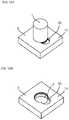
- the disclosureconcerns a set of elements for an assembled product, such as illustrated in FIG. 7A in a crosscut side view.
- the embodiment of the setcomprises a first element 1 with a cylindrical shaped part 3 , a second element 2 having a cylindrical shaped groove 4 with a circular opening 75 in an outer surface 74 of the second element, and a mechanical locking device.
- the mechanical locking devicecomprises a tongue groove 10 , a displacement groove 20 and a flexible tongue 30 in the displacement groove 20 .
- the mechanical locking deviceis configured to lock the cylindrical shaped part 3 to the cylindrical shaped groove 4 .
- the flexible tongue 30is configured to cooperate with the tongue groove 10 for locking the cylindrical shaped part 3 to the cylindrical shaped groove 4 , wherein the flexible tongue 30 is configured to be reshaped and displaced in the displacement groove 20 during a locking of the cylindrical shaped part 3 to the cylindrical shaped groove 4 and spring back to a locked position.
- the flexible tongueis configured to exert a spring force on the tongue groove 10 in the locked position.
- the flexible tonguecomprises a main body which has an at least partly circular shape in a plane parallel to the circular opening 75 .
- An envelope surface 72 of the cylindrical shaped groove 4 and an envelope surface 71 of the cylindrical shaped part 3are configured to cooperate in a locked position of the first element 1 and the second element 2 .
- the flexible tongue and the tongue groovemay be configured to cooperate for a locking of the first element and the second element in a first direction.
- the envelope surface of the cylindrical shaped groove and the envelope surface of the cylindrical shaped partmay be configured to cooperate for a locking of the first element and the second element in a second direction which is perpendicular to the first direction.
- the first element in this and other embodimentmay comprise one or several of said cylindrical shaped part 3 and the second element 2 may comprise corresponding numbers or more of said cylindrical shaped groove 4 .
- the first elementis configured to be assembled to the second element 2 by a relative displacement of the cylindrical shaped part 3 through the circular opening 75 and into the cylindrical shaped groove 4 to a locked position of the first element 1 and the second element 2 , wherein the flexible tongue 30 is configured to be reshaped and displaced in the displacement groove during said relative displacement.
- An envelope surface 71 of the cylindrical shaped part 3comprises in this embodiment the displacement groove 20
- an envelope surface 72 of the cylindrical shaped groove 4comprises the tongue groove 10 .
- the flexible tongue 30 of this embodimentis configured to be attached to the circular part 3 before the first element 1 is assembled to the second element 2 .
- the flexible tongue 30comprises a first edge 46 which is at least partly circular, see e.g. FIGS. 1A-2D and FIGS. 5A-D .
- Said first edgecomprises a locking surface 33 which is configured to cooperate with a locking surface 11 of the tongue groove 10 .
- FIG. 7Bwhich is an enlargement of the encircled are in FIG. 7A .
- the second edge 47is in this embodiment closer to a centre of the cylindrical shaped part 3 than the first edge 46 .
- the locking surface 11preferably angled in relation to a displacement direction 21 of the displaceable tongue 30 in the displacement groove 20 .
- An end surface 73 of the first element 1may be configured to cooperate with the outer surface 74 of the second element 2 in a locked position of the first element 1 and the second element 2 .
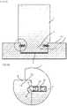
- FIG. 8Ashows a 3D-view an embodiment of the set shown in FIGS. 7A-7B .
- FIG. 8Bshows an embodiment of the second element 2 of the set shown in FIGS. 7A-7B .
- the embodimentcomprises one or more dismantling grooves 90 in the outer surface 74 of the second element 2 .
- a tool 95 with a longitudinal part 91is configured to be inserted into the dismantling groove 90 and to unlock the mechanical locking device.
- the longitudinal part 91may be bendable such that, when the longitudinal part 91 is inserted into dismantling groove 90 and the tongue groove 10 , the shape of longitudinal part 91 adapts to the shape of the dismantling groove 90 and the tongue groove 10 .
- the dismantling grooveextends into the tongue groove 10 .
- FIG. 8Cshows, in an enlarged crosscut, the mechanical locking device during in an unlocked position.
- a cross section of the longitudinal part 91 of the toolhas unlocked the mechanical locking device by pushing the flexible tongue into the displacement groove 20 .
- the tool 95may have a handle 92 .
- the first elementmay be panel shaped or rod shaped with a rectangular or circular cross-section.
- the second elementmay be panel shaped or rod shaped with a rectangular or circular cross-section.
- the first elementmay be e.g. a leg or rod for a furniture, such as a table, a desk, a chair or a cabinet.
- the second elementmay be a panel for a furniture, such as a table, a desk, a chair or a cabinet.
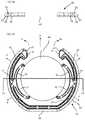
- FIG. 1BAn embodiment of the flexible tongue 30 is shown in a bottom view in FIG. 1B and a cross section, along a line indicated by 1 A- 1 A in FIG. 1B , is shown in FIG. 1A .
- the embodimentis shown in a 3D-view in FIG. 2A , in a side view in FIG. 2B an in a bottom view in FIGS. 2C-2D .
- the embodimentcomprises a first edge 46 which is at least partly circular and comprises a locking surface 33 which is configured to cooperate with the locking surface 11 of the tongue groove 10 .
- the embodiment of the locking surface 33 of the flexible tongue 30has a first enclosing angle 61 and a second enclosing angle 62 .
- Each of the first and the second enclosing angleis about 120°, i.e. the total enclosing angle is about 240°.
- Embodiments of the flexible tonguemay have one continuous locking surface or several locking surfaces.
- An enclosing angle of the locking surfacemay be more than about 90°, preferably in the range of about 100° to about 300°, preferably about 240°.
- the embodiment of the flexible tongue 30comprises a second edge 47 which is at least partly circular, said second edge comprises three or more flexible elements 35 , 36 , 37 , 38 for positioning of the flexible tongue 30 relative the cylindrical shaped part 3 and/or the cylindrical shaped groove 4 .
- the flexible elements 35 , 36 , 37 , 38protrude towards a bottom of the displacement groove 20 .
- the spring forcemay originate at least partly from a reshape of flexible elements 35 , 36 , 37 , 38 from a first shape in an unlocked position to a second shape in the locked position
- the main body of the embodimentcomprises a first protruding part 43 at a first position and a second protruding part 44 at a second position.
- a first flexible element 35 and a second flexible element 37are extending from the first protruding part 43 .
- the first flexible element 35may extend in a different or essentially opposite direction to the second flexible element 37 .
- a third flexible element 36 and a fourth flexible element 38are extending from the second protruding part 44 .
- the third flexible element 37may extend in a different or essentially opposite direction to the fourth flexible element 38 .
- the first protruding part 43may be poisoned opposite or essentially opposite to the second protruding part 44 .
- the embodiment of flexible tongue 30may enclose completely or at least partly the cylindrical shaped part 3 .
- the embodimentmay enclose the cylindrical shaped part 3 with an enclosing angle 65 which is more than about 180°, or in the range of about 330° to about 360°, or about 345° to about 355°.
- the displacement groovemay comprise one or several of said flexible tongue with an enclosing angle 65 which is in the range of about 90° to about 180°.
- the spring forcemay originate at least partly from a reshape of the main body from a first shape in an unlocked position to a second shape in the locked position.
- the reshape of the main bodymay contribute to about more than 50% or about 80% to about 95% of the spring force.
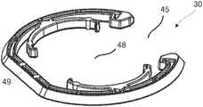
- the main body of the embodiment of the flexible tongue 30comprises a central groove 48 , which extends through the main body.
- the main bodycomprises a split groove 45 which extends from an envelope surface of the main body to the central groove 48 of the main body.
- the split groove 45is configured for facilitating assembling of the flexible tongue 30 in the displacement groove 20 .
- the embodiment of the flexible tongue 30is during the assembling in the displacement groove displaced 11 relative the cylindrical part 3 .
- a first part of the flexible tongue at a first side of the split groove and second part of the flexible tonguemay be pushed away from each other, such that the split groove is enlarged.
- the enlarged split groovemay facilitate an attachment of the flexible tongue in the displacement groove of the cylindrical part.
- the main bodymay comprise one or more guiding surfaces 40 , 41 at the split groove.
- the guiding surfaces 40 , 41are configured for facilitating assembling of the flexible tongue on the cylindrical shaped part 3 .
- a first guiding surface 40may extend in a different direction than a second guiding surface 41 , such that the first guiding surface cooperate, during said assembling, with the cylindrical part 3 before the second guiding surface cooperate with the cylindrical part 3 .
- the main body of the embodiment of the flexible tongue 30may comprise a straight part 49 which is configured to decrease the bending resistance of the main body.
- the straight part 48may have an enclosing angle 63 which is in the range of about 5° to about 45°, preferably about 55°.
- the straight partmay have the advantage that the attachment of the flexible tongue in the displacement groove is facilitated and/or that the main body does not break during the attachment.
- the main body of the embodiment of the flexible tongue 30may comprise one or more grooves 42 which is/are configured to decrease the bending resistance of the main body.
- the grooves 42may have the advantage that the attachment of the flexible tongue in the displacement groove is facilitated and/or that the main body does not break during the attachment.
- the flexible tonguemay be configured to exert a spring force F, in the locked position, on the tongue groove at least at two opposite positions of the circular part.
- the flexible tonguemay be configured to exert a spring force F with several directions, such as perpendicular to each other and/or opposite to each other. This may have the effect that the cylindrical shaped part is firmly locked to the cylindrical shaped groove.
- the embodiment of the flexible tongue 30is configured to exert a spring force, in the locked position, on the tongue groove at least at two opposite positions of the circular part 3 .
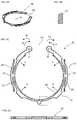
- FIG. 5AAn embodiment of the flexible tongue 30 is shown in a 3D view in FIG. 5A , a cross section, along a line indicated by 5 A-A in FIG. 5D , in FIG. 5B .
- the embodimentis shown in side view in FIG. 5C and in a bottom view in FIG. 5D .
- the embodimentcomprises a catch device 31 , such as a groove.
- the catch deviceis configured to be caught by a second tool, such as pliers.
- the second toolis configured to displace, as shown by arrows 14 in FIG. 5D , a first part of the flexible tongue towards a second part of the flexible tongue, such that the mechanical locking device is unlocked and the first element may be disassembled from the second element.
- the flexible tonguemay be unlocked by inserting the tool in an embodiment of the dismantling grooves 90 that is shown in FIG. 12A in a 3D-view.
- the embodiment of the setcomprises a first element 1 , a second element 2 .
- An outer surface of the second elementcomprises the dismantling groove 90 ;
- FIG. 12Bis a 3D-view of the second element in FIG. 12A .
- FIG. 9AAn embodiment of the set is shown in FIG. 9A .
- the embodimentcomprises a first element 1 with a cylindrical shaped part 3 , a second element 2 having a cylindrical shaped groove 3 with a circular opening 75 in an outer surface 74 of the second element, and a mechanical locking device.
- the mechanical locking devicecomprises a tongue groove 10 , a displacement groove 20 and a flexible tongue 3 in the displacement groove 20 .
- the mechanical locking deviceis configured to lock the cylindrical shaped part 3 to the cylindrical shaped groove 4 .
- the flexible tongue 30is configured to cooperate with the tongue groove 10 for locking the cylindrical shaped part 3 to the cylindrical shaped groove 4 , wherein the flexible tongue 30 is configured to be reshaped and displaced in the displacement groove 20 during a locking of the cylindrical shaped part 3 to the cylindrical shaped groove 4 and spring back to a locked position.
- the flexible tongueis configured to exert a spring force on the tongue groove 10 in the locked position.
- the flexible tonguecomprises a main body which has an at least partly circular shape in a plane parallel to the circular opening 75 .
- An envelope surface 72 of the cylindrical shaped groove 4 and an envelope surface 71 of the cylindrical shaped part 3are configured to cooperate in a locked position of the first element 1 and the second element 2 .
- the flexible tongue and the tongue groovemay be configured to cooperate for a locking of the first element and the second element in a first direction.
- the envelope surface of the cylindrical shaped groove and the envelope surface of the cylindrical shaped partmay be configured to cooperate for a locking of the first element and the second element in a second direction which is perpendicular to the first direction.
- the first element in this and other embodimentmay comprise one or several of said cylindrical shaped part 3 and the second element 2 may comprise corresponding numbers or more of said cylindrical shaped groove 4 .
- the first elementis configured to be assembled to the second element 2 by a relative displacement of the cylindrical shaped part 3 through the circular opening 75 and into the cylindrical shaped groove 4 to a locked position of the first element 1 and the second element 2 , wherein the flexible tongue 30 is configured to be reshaped and displaced in the displacement groove during said relative displacement.
- An envelope surface 72 of the cylindrical shaped groove 4comprises in this embodiment the displacement groove 20 , and an envelope surface 72 of the cylindrical shaped part 3 comprises the tongue groove 10 .
- the flexible tonguemay be configured to exert a spring force F, in the locked position, on the tongue groove at least at two opposite positions of the circular part.
- the flexible tongue 30 of this embodimentis configured to be attached to the cylindrical groove 4 before the first element 1 is assembled to the second element 2 .
- the flexible tongue 30comprises a first edge 46 which is at least partly circular; see e.g. FIGS. 3A-4D and FIGS. 6A-D .
- Said first edgecomprises a locking surface 33 which is configured to cooperate with a locking surface 11 of the tongue groove 10 .
- FIG. 9Bwhich is an enlargement of the encircled are in FIG. 9A .
- the first edge 46is in these embodiments closer to a centre of the cylindrical shaped groove 4 than second edge 47 .
- FIGS. 3A-3Dshow an embodiment of the flexible tongue 30 configured for the embodiment of the set shown in FIGS. 9A-9B .
- the embodimentcomprises a catch device 31 , such as a groove.
- the catch deviceis configured to be caught by a second tool, such as pliers.
- the second toolis configured to displace, as shown by arrows 12 in FIG. 3C , a first part of the flexible tongue towards a second part of the flexible tongue, such that the flexible tongue may be inserted in the displacement groove 20 .
- the first partmay be displaced to a position in which it overlaps the second part when the flexible tongue is inserted in the displacement groove.
- the second toolis configured to displace, as shown by arrows 14 in FIG. 3C , a first part of the flexible tongue away from a second part of the flexible tongue, such that the mechanical locking device is unlocked.
- the second toolmay be inserted into an embodiment of the dismantling groove 90 shown in FIGS. 12A-12B .
- FIGS. 4A-4Dshow an embodiment of the flexible tongue 30 configured for the embodiment of the set shown in FIGS. 9A-9B .
- the embodimentcomprises a catch device 31 , such as a groove.
- the catch deviceis configured to be caught by a second tool, such as pliers.
- the second toolis configured to displace, as shown by arrows 12 in FIG. 4C , a first part of the flexible tongue towards a second part of the flexible tongue, such that the flexible tongue may be inserted in the displacement groove 20 .
- the first partmay is in this embodiment positioned at a larger distance from the second part. The distance will decrease when the flexible tongue is inserted in the displacement groove.
- the second toolis configured to displace, as shown by arrows 14 in FIG. 4C , a first part of the flexible tongue away from a second part of the flexible tongue, such that the mechanical locking device is unlocked.
- the second toolmay be inserted into an embodiment of the dismantling groove 90 shown in FIGS. 12A-12B
- the flexible tonguemay be configured to exert a spring force F with several directions, such as perpendicular to each other and/or opposite to each other. This may have the effect that the cylindrical shaped part is firmly locked to the cylindrical shaped groove.
- FIGS. 6A-6Dshow an embodiment of the flexible tongue 30 configured for the embodiment of the set shown in FIGS. 9A-9B .
- This embodimentdoes not comprise a catch device.
- An embodiment of the mechanical locking device comprising this embodiment of the flexible tonguemay be unlocked with an embodiment of the tool 95 with a longitudinal part 91 , as shown in FIG. 8A and described above, which is configured to be inserted into the dismantling groove 90 .
- the locking surface 11preferably angled in relation to a displacement direction 21 of the displaceable tongue 30 in the displacement groove 20 .
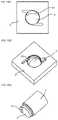
- FIG. 10Ashows a 3D-view an embodiment of the set shown in FIGS. 9A-9B .
- FIG. 9Bshows an embodiment of the second element 2 of the set shown in FIGS. 9A-9B .
- the embodimentcomprises one or more dismantling grooves 90 in a surface 76 of the element 1 .
- the tool 95 with the longitudinal part 91is configured to be inserted into the dismantling groove 90 and to unlock the mechanical locking device.
- the dismantling grooveextends into the tongue groove 10 .
- FIG. 10Cshows in an enlarged crosscut the mechanical locking device during in an unlocked position. A cross section of the longitudinal part 91 of the tool 95 has unlocked the mechanical locking device by pushing the flexible tongue into the displacement groove 20 .
- FIGS. 9A-9BThe set shown in FIGS. 9A-9B is shown in a locked position in a first crosscut view in FIG. 11A , the cross section is indicated by the line 11 A- 11 A in the top view of the set shown in FIG. 11B .
- a second crosscut viewis shown in in FIG. 11C , the cross section is indicated by the line 11 C- 11 C in the top view of the set shown in FIG. 11B .
- a side view of the setis shown in FIG. 11D .
- FIG. 11Cshows a first of said dismantling groove 90 at a first side of the first element 1 and a second of said dismantling groove 90 at a second side of the first element 1 .
- FIGS. 13A-16Cshow embodiments of the set comprising a lock 81 for preventing a rotation of the first element 1 relative the second element.
- the lock 81may comprise e.g. a groove on the first element 1 and a protruding part on the second element 2 or a protruding part on the first element 1 and a groove on the second element.
- FIGS. 13A-13DAn embodiment of the lock 81 is shown in FIGS. 13A-13D comprising a groove on a bottom surface 6 of the cylindrical shaped groove 4 and a protruding part on a bottom surface 5 of the cylindrical shaped part 3 .
- the protruding partis configured to cooperate with the groove for preventing a rotation of the first element 1 relative the second element 2 in a locked position of the first element and the second element.
- the embodimentis shown in a top view in FIG. 13A , in a side view in FIG. 13B , an in a 3D-view in FIG. 13C-13D .
- FIGS. 14A-14DAn embodiment of the lock 81 is shown in FIGS. 14A-14D comprising a groove on the outer surface 74 of the second element 2 and protruding part on a bottom surface 73 of the first element.
- the protruding partis configured to cooperate with the groove for preventing a rotation of the first element 1 relative the second element 2 in a locked position of the first element and the second element.
- the embodimentis shown in a 3D view in FIGS. 14A-C .
- FIGS. 15A-16CAn embodiment of the lock 81 is shown in FIGS. 15A-16C comprising a longitudinal shaped groove on a bottom surface 6 of the cylindrical shaped groove 4 and a longitudinal shaped protruding part on a bottom surface 5 of the cylindrical shaped part 3 .
- the protruding partis configured to cooperate with the groove for preventing a rotation of the first element 1 relative the second element 2 in a locked position of the first element and the second element.
- the embodimentis shown in a top view in FIG. 15B with lines 15 A- 15 A and 15 C- 15 C which indicate the cross sections shown in FIGS. 15A and 15C , respectively.
- the first element 1may comprise a wood based material, a polymer material or a metal.
- the second element 2a wood based material or a polymer material.
- the locking devicemay be essentially formed by the mechanical cutting, such as milling, in the material of the first element and the second element.
- the flexible tonguemay comprise a polymer material, preferably with an enforcement, such as glass fibre.
- the flexible tonguemay be produced by injection moulding.
- the second elementmay comprise a reinforcement plate comprising the circular opening 75 .
- the reinforcement platemay comprise the locking surface 11 .
- the first element 1may be an integral part of a furniture, i.e. formed in a furniture element, or a separate part attached to the furniture.
- the second element 2may be an integral part of a furniture, i.e. formed in a furniture element, or a separate part attached to the furniture.
- a setcomprising:
- a second element ( 2 )having a cylindrical shaped groove ( 4 ) with a circular opening ( 75 ) in an outer surface ( 74 ) of the second element;
- a mechanical locking devicecomprising a tongue groove ( 10 ), a displacement groove ( 20 ) and a flexible tongue ( 30 ) in the displacement groove ( 20 ), wherein the mechanical locking device is configured to lock the cylindrical shaped part ( 3 ) to the cylindrical shaped groove ( 4 ), characterised in
- the flexible tongue ( 30 )is configured to cooperate with the tongue groove ( 10 ) for locking the cylindrical shaped part ( 3 ) to the cylindrical shaped groove ( 4 ),
- the flexible tongue ( 30 )is configured to be reshaped and displaced in the displacement groove ( 20 ) during a locking of the cylindrical shaped part ( 3 ) to the cylindrical shaped groove ( 4 ) and spring back to a locked position
- the flexible tongueis configured to exert a spring force on the tongue groove ( 10 ) in the locked position
- the flexible tonguecomprises a main body which has an at least partly circular shape in a plane parallel to the circular opening ( 75 ).
- the flexible tongue ( 30 )comprises a first edge ( 46 ) which is at least partly circular, and wherein said first edge comprises a locking surface ( 33 ) which is configured to cooperate with a locking surface ( 11 ) of the tongue groove ( 10 ).
- the flexible tongue ( 30 )comprises a second edge ( 47 ) which is at least partly circular, said second edge comprises three or more flexible elements ( 35 , 36 , 37 , 38 ) for positioning of the flexible tongue ( 30 ) relative the cylindrical shaped part ( 3 ) and/or the cylindrical shaped groove ( 4 ).
- the main bodycomprises a split groove ( 45 ) which extends from an envelope surface of the main body to the central groove of the main body, wherein the split groove ( 45 ) is configured for facilitating assembling of the flexible tongue ( 30 ) in the displacement groove ( 20 ).
- the main bodycomprises one or more guiding surfaces ( 40 , 41 ) at the split groove, wherein the guiding surfaces ( 40 , 41 ) are configured for facilitating assembling of the flexible tongue on the cylindrical shaped part.
- the main bodycomprises a straight part ( 49 ) which is configured to decrease the bending resistance of the main body, the straight part ( 49 ) preferably having an enclosing angle ( 63 ) which is in the range of about 5° to about 45°, preferably about 20°.
- main bodycomprises one or more grooves ( 42 ) which is/are configured to decrease the bending resistance of the main body.
- first element ( 1 )is configured to be assembled to the second element ( 2 ) by a relative displacement of the cylindrical shaped part ( 3 ) through the circular opening ( 75 ) and into the cylindrical shaped groove ( 4 ) to a locked position of the first element and the second element, wherein the flexible tongue ( 30 ) is configured to be reshaped and displaced in the displacement groove during said relative displacement.
Landscapes
- Engineering & Computer Science (AREA)
- General Engineering & Computer Science (AREA)
- Mechanical Engineering (AREA)
- Snaps, Bayonet Connections, Set Pins, And Snap Rings (AREA)
- Furniture Connections (AREA)
- Clamps And Clips (AREA)
Abstract
Description
Claims (19)
Applications Claiming Priority (2)
| Application Number | Priority Date | Filing Date | Title |
|---|---|---|---|
| SE1750593 | 2017-05-15 | ||
| SE1750593-4 | 2017-05-15 |
Publications (2)
| Publication Number | Publication Date |
|---|---|
| US20180328396A1 US20180328396A1 (en) | 2018-11-15 |
| US11506235B2true US11506235B2 (en) | 2022-11-22 |
Family
ID=64095990
Family Applications (1)
| Application Number | Title | Priority Date | Filing Date |
|---|---|---|---|
| US15/978,630Active2040-11-30US11506235B2 (en) | 2017-05-15 | 2018-05-14 | Elements and a locking device for an assembled product |
Country Status (8)
| Country | Link |
|---|---|
| US (1) | US11506235B2 (en) |
| EP (1) | EP3625464B1 (en) |
| JP (1) | JP7201617B2 (en) |
| CN (1) | CN110621889A (en) |
| EA (1) | EA038797B1 (en) |
| HR (1) | HRP20230089T1 (en) |
| MY (1) | MY196739A (en) |
| WO (1) | WO2018212701A1 (en) |
Cited By (4)
| Publication number | Priority date | Publication date | Assignee | Title |
|---|---|---|---|---|
| US20220018373A1 (en)* | 2020-07-17 | 2022-01-20 | Välinge Innovation AB | Mechanical locking system for panels |
| US20220213912A1 (en)* | 2021-01-07 | 2022-07-07 | Välinge Innovation AB | Wedge-shaped tongue groove |
| US11788567B2 (en) | 2019-12-19 | 2023-10-17 | Valinge Innovation Ab | Set of panels with a mechanical locking device |
| US12408748B2 (en) | 2018-08-30 | 2025-09-09 | Välinge Innovation AB | Set of panels with a mechanical locking device |
Families Citing this family (44)
| Publication number | Priority date | Publication date | Assignee | Title |
|---|---|---|---|---|
| UA109938C2 (en) | 2011-05-06 | 2015-10-26 | MECHANICAL LOCKING SYSTEM FOR CONSTRUCTION PANELS | |
| US9726210B2 (en) | 2013-09-16 | 2017-08-08 | Valinge Innovation Ab | Assembled product and a method of assembling the product |
| CN109854597B (en) | 2013-09-16 | 2021-03-19 | 瓦林格创新股份有限公司 | Combination product and method for assembling the same |
| US9714672B2 (en) | 2014-01-10 | 2017-07-25 | Valinge Innovation Ab | Panels comprising a mechanical locking device and an assembled product comprising the panels |
| EP3851684A1 (en) | 2014-05-09 | 2021-07-21 | Välinge Innovation AB | Mechanical locking system for building panels |
| ES2758673T3 (en) | 2014-12-19 | 2020-05-06 | Vaelinge Innovation Ab | Panels comprising a mechanical locking device |
| EP3285620A4 (en) | 2015-04-21 | 2018-11-14 | Välinge Innovation AB | Panel with a slider |
| KR20170141223A (en) | 2015-04-30 | 2017-12-22 | 뵈린게 이노베이션 에이비이 | A panel having a fastening device |
| UA125554C2 (en) | 2015-09-22 | 2022-04-20 | Велінге Інновейшн Аб | Panels comprising a mechanical locking device and an assembled product comprising the panels |
| MX2018006522A (en) | 2015-12-03 | 2018-11-29 | Vaelinge Innovation Ab | Panels comprising a mechanical locking device and an assembled product comprising the panels. |
| EP3407765B1 (en) | 2016-01-26 | 2021-03-03 | Välinge Innovation AB | Panels comprising a mechanical locking device to obtain a furniture product |
| KR20180109957A (en) | 2016-02-04 | 2018-10-08 | 뵈린게 이노베이션 에이비이 | Set of panels for assembled products |
| US10415613B2 (en) | 2016-02-09 | 2019-09-17 | Valinge Innovation Ab | Set of panel-shaped elements for a composed element |
| CA3011703A1 (en) | 2016-02-09 | 2017-08-17 | Valinge Innovation Ab | Element and method for providing dismantling groove |
| JP6921834B2 (en) | 2016-02-15 | 2021-08-18 | ベーリンゲ、イノベイション、アクチボラグVaelinge Innovation Ab | How to form panels for furniture products |
| CN117703894A (en) | 2016-10-27 | 2024-03-15 | 瓦林格创新股份有限公司 | Panel assembly with mechanical locking means |
| GB2554537B (en)* | 2017-08-14 | 2018-11-07 | Smart Garden Products Ltd | A shelf system for growing plants |
| CN111465773B (en) | 2017-12-22 | 2021-11-02 | 瓦林格创新股份有限公司 | Panel set, method for assembling the panel set and locking device for furniture products |
| RU2740868C1 (en) | 2017-12-22 | 2021-01-21 | Велинге Инновейшн Аб | Set of panels, method of their assembling and locking device for furniture product |
| MY204146A (en) | 2018-03-23 | 2024-08-09 | Vlinge Innovation Ab | Panels comprising a mechanical locking device and an assembled product comprising the panels |
| PL3781822T3 (en) | 2018-04-18 | 2024-11-18 | Välinge Innovation AB | Set of panels with a mechanical locking device |
| EA202092409A1 (en) | 2018-04-18 | 2021-02-26 | Велинге Инновейшн Аб | SYMMETRIC TONGUE AND T-SHAPED KNOT |
| PL3781824T3 (en) | 2018-04-18 | 2024-06-24 | Välinge Innovation AB | Set of panels with a mechanical locking device |
| US11448252B2 (en) | 2018-04-18 | 2022-09-20 | Valinge Innovation Ab | Set of panels with a mechanical locking device |
| US11614114B2 (en) | 2018-04-19 | 2023-03-28 | Valinge Innovation Ab | Panels for an assembled product |
| DE202019100109U1 (en)* | 2019-01-10 | 2020-04-16 | Innotec Motion GmbH | Seating chassis |
| EP3730807A1 (en) | 2019-04-26 | 2020-10-28 | Välinge Innovation AB | Set of panels with a mechanical locking device |
| DE102019206427A1 (en)* | 2019-05-03 | 2020-11-05 | Franz Baur | Connecting device and furniture |
| EP3834661A1 (en) | 2019-12-11 | 2021-06-16 | Välinge Innovation AB | Mechanical locking system for panels |
| EP4090198B1 (en)* | 2020-01-13 | 2025-08-20 | Välinge Innovation AB | A set comprising a panel and a pull grip arranged with a mechanical locking mechanism |
| WO2021150162A1 (en) | 2020-01-22 | 2021-07-29 | Välinge Innovation AB | Set of panels with a mechanical locking device |
| EP3871560A1 (en) | 2020-02-26 | 2021-09-01 | Välinge Innovation AB | Set of panels with a mechanical locking device |
| EP3871559A1 (en) | 2020-02-26 | 2021-09-01 | Välinge Innovation AB | Set of panels with a mechanical locking device |
| US11702844B2 (en) | 2020-06-05 | 2023-07-18 | Valinge Innovation Ab | Building panels comprising a locking device |
| US11246419B2 (en)* | 2020-07-19 | 2022-02-15 | Festival Trading Inc. | Screwless chair |
| CN112008816A (en)* | 2020-09-08 | 2020-12-01 | 舒生平 | Wood board mounting groove machining method and wood board mounting assembly |
| DE102020124086A1 (en) | 2020-09-16 | 2022-03-17 | Deutsches Zentrum für Luft- und Raumfahrt e.V. | coupling device |
| EP4258943A4 (en) | 2020-12-11 | 2024-10-23 | Välinge Innovation AB | RAIL FOR CABINETS |
| WO2022159013A1 (en) | 2021-01-19 | 2022-07-28 | Välinge Innovation AB | A set of panels, a method for assembly of the same and a locking device for a furniture product |
| US12071769B2 (en) | 2021-02-03 | 2024-08-27 | Valinge Innovation Ab | Building panels comprising a locking device |
| US12247598B2 (en) | 2021-02-08 | 2025-03-11 | Välinge Innovation AB | Mounting bracket |
| WO2022184446A1 (en) | 2021-03-01 | 2022-09-09 | Välinge Innovation AB | Mechanical connection arrangement for panels |
| EP4352370A4 (en) | 2021-06-11 | 2025-04-09 | Välinge Innovation AB | LOCKING DEVICE WITH A SPRING AND A LOCKING PIN AND SET WITH FURNITURE COMPONENTS AND THE LOCKING DEVICE |
| WO2024172729A1 (en)* | 2023-02-14 | 2024-08-22 | Välinge Innovation AB | Building panel with a mechanical locking system |
Citations (319)
| Publication number | Priority date | Publication date | Assignee | Title |
|---|---|---|---|---|
| DE228872C (en) | ||||
| US291032A (en) | 1884-01-01 | Isaac g- | ||
| US634581A (en) | 1898-11-21 | 1899-10-10 | Robert H Miller | Carpenter's square. |
| US701000A (en) | 1901-07-31 | 1902-05-27 | Carl F W Ahrens | File-cabinet. |
| US861911A (en) | 1905-11-04 | 1907-07-30 | William Stewart | Joint for articles of furniture or woodwork. |
| US881673A (en) | 1907-03-11 | 1908-03-10 | Arthur L Ellison | Wardrobe or safe. |
| US1533099A (en) | 1924-07-14 | 1925-04-14 | Robert E Carroll | Square-corner glue joint |
| US1534468A (en) | 1922-10-30 | 1925-04-21 | Jr John J Shea | Joint structure |
| GB245332A (en) | 1925-05-04 | 1926-01-07 | George Hugh Foster | An improved dowelled joint for woodwork and the like |
| US1800387A (en) | 1926-12-30 | 1931-04-14 | Andrew Hoffman Mfg Company | Article-supporting device |
| US1800386A (en) | 1926-08-28 | 1931-04-14 | Andrew Hoffman Mfg Company | Display rail |
| US1802245A (en) | 1930-08-26 | 1931-04-21 | Clarence L Foretich | Display stand and shelving |
| US1954242A (en) | 1932-07-28 | 1934-04-10 | Thomas E Heppenstall | Dovetail spring joint |
| US2360451A (en) | 1942-06-02 | 1944-10-17 | Stone Abraham | Collapsible clothing container |
| US2362904A (en) | 1943-01-20 | 1944-11-14 | Allied Purchasing Corp | Joint for demountable furniture |
| US2496184A (en) | 1946-06-11 | 1950-01-31 | Canon Paul L Von | Furniture drawer construction and method |
| US2681483A (en) | 1948-10-14 | 1954-06-22 | Morawetz Hugo | Dowel connection |
| FR1155424A (en)* | 1955-08-09 | 1958-04-28 | Waldes Koh I Noor | Axial coupling for one shaft and one housing |
| DE1107910B (en) | 1957-03-26 | 1961-05-31 | Curt Weinert | Flexible duebel |
| US3002630A (en) | 1960-05-24 | 1961-10-03 | Robert E Heisser | Toothbrush rack |
| CH365507A (en) | 1958-11-17 | 1962-11-15 | Antonius Bus Johannes | Device for connecting perpendicular walls with automatic locking, in particular furniture walls |
| US3195968A (en) | 1962-12-06 | 1965-07-20 | Lok Trim Corp | Knock-down furniture |
| GB1022377A (en) | 1963-08-19 | 1966-03-09 | Trepatent As | Arrangement of building sections for cupboards, benches or other equipment |
| US3284152A (en) | 1963-03-07 | 1966-11-08 | Kuche Und Haustechnik G M B H | Knockdown furniture |
| US3313054A (en) | 1965-06-09 | 1967-04-11 | Poster Products Inc | Display devices |
| US3347610A (en) | 1966-07-28 | 1967-10-17 | Pilliod Cabinet Company | Cabinet construction |
| US3410441A (en) | 1966-06-29 | 1968-11-12 | Jeff S. Rhyne | Container |
| FR2062731A5 (en) | 1969-11-06 | 1971-06-25 | Hefendehl Hansfriedrich | |
| US3722704A (en) | 1970-07-23 | 1973-03-27 | Castelli Sas Anonima | Structural components for the composition of disassemblable pieces offurniture |
| US3742807A (en) | 1972-02-03 | 1973-07-03 | D Manning | Leveling and locking pin |
| US3765465A (en) | 1972-01-05 | 1973-10-16 | Deutsch Fastener Corp | Retractable captive fastener |
| US3784271A (en) | 1972-06-22 | 1974-01-08 | Schreiber Furniture Ltd | Kitchen cabinets |
| US3884002A (en) | 1973-03-15 | 1975-05-20 | American Store Equip | Partition system |
| US3885845A (en) | 1974-06-27 | 1975-05-27 | Hans Krieks | Knock-down furniture system |
| DE2414104A1 (en) | 1974-03-23 | 1975-10-09 | Alfer Alu Fertigbau | Fastener for wooden shelving - comprises straight locking pins engaged by pressure of support plate |
| DE2514357A1 (en) | 1974-04-02 | 1975-10-16 | Takeshi Shimizu | Dowel pins for furniture panel assembly - have inclined locations to provide self locking linkage |
| US3981118A (en) | 1974-10-17 | 1976-09-21 | The Goodyear Tire & Rubber Company | Clamping insert |
| DE2635237A1 (en) | 1976-08-05 | 1978-02-09 | Heinze Fa R | FURNITURE HINGE |
| US4089614A (en) | 1976-05-12 | 1978-05-16 | Itw Limited | Furniture connector |
| US4099887A (en) | 1977-07-18 | 1978-07-11 | Einhard Mackenroth | Structural joints |
| US4099293A (en) | 1975-12-02 | 1978-07-11 | Firma Richard Heinze | Cabinet hinge |
| JPS53113160U (en) | 1977-02-16 | 1978-09-08 | ||
| US4116510A (en) | 1977-03-03 | 1978-09-26 | Gte Automatic Electric Laboratories Incorporated | Chassis formed of sheet stock |
| US4211379A (en) | 1978-11-20 | 1980-07-08 | Morgan Myron B | Panelboard and mounting fixture combination |
| US4222544A (en) | 1977-08-10 | 1980-09-16 | Kenneth Crowder | Picture rail apparatus |
| US4279397A (en) | 1978-08-28 | 1981-07-21 | Hafa Fabriks Ab | Attachment for wall cabinets, mirrors, shelves and similar articles |
| US4299067A (en) | 1979-10-30 | 1981-11-10 | J. C. Penney Company, Inc. | Partition connector system |
| US4308961A (en) | 1980-05-05 | 1982-01-05 | Kunce Thomas M | Article supporting structure |
| US4314500A (en)* | 1980-01-25 | 1982-02-09 | The United States Of America As Represented By The Secretary Of The Air Force | Instantaneous opening positive lock mechanism |
| US4324517A (en) | 1980-06-16 | 1982-04-13 | Sps Technologies, Inc. | Panel fastener assembly with retainer ring |
| DE3103281A1 (en) | 1981-01-31 | 1982-08-12 | C + A Dick GmbH, 5275 Bergneustadt | Material cabinet |
| EP0060203A2 (en) | 1981-03-10 | 1982-09-15 | Roland Haeusler | Tenon-and-mortise type connection, and furniture incorporating the same |
| FR2517187A1 (en) | 1981-12-01 | 1983-06-03 | Beaux Dominique | DETACHABLE BOX FOR FURNITURE USE |
| US4405253A (en) | 1977-12-20 | 1983-09-20 | Stockum Bernt I | Connection between two elements |
| US4471978A (en)* | 1978-06-07 | 1984-09-18 | Dieter Kramer | Push-pull connecting system for pressure lines, brake-system lines in particular |
| US4509648A (en) | 1982-07-26 | 1985-04-09 | The Stanley Works | Merchandising display system and components therefor |
| GB2163825A (en) | 1984-08-30 | 1986-03-05 | Hettich Paul Gmbh & Co | Furniture connector |
| US4593734A (en) | 1983-09-26 | 1986-06-10 | M. Bosley Wright | Frame routing apparatus |
| US4595105A (en) | 1984-09-12 | 1986-06-17 | Gold Kenneth S | Interlocking bookrack |
| US4597122A (en) | 1985-06-10 | 1986-07-01 | Hirsh Company | Free-standing drawer |
| US4615448A (en) | 1985-09-27 | 1986-10-07 | Masonite Corporation | Display panel |
| US4629076A (en) | 1984-05-10 | 1986-12-16 | Amstore Corporation | Slatboard |
| FR2597173A1 (en) | 1986-04-10 | 1987-10-16 | Forschle Andre | DEVICE FOR EASILY ASSEMBLING AND MODIFYING THE COMPOSITION OF A KITCHEN FURNITURE |
| WO1987007339A1 (en) | 1986-05-23 | 1987-12-03 | William Rodney George | Joint between members and an article constructed by employing the joint |
| FR2602013A1 (en) | 1986-07-25 | 1988-01-29 | Kapikian Jean Claude | Assembly system of the mortice and tenon type which can be easily mounted and dismounted |
| US4750794A (en) | 1984-11-21 | 1988-06-14 | Bass Cabinet Manufacturing, Inc. | Slide-fitted article of furniture |
| US4752150A (en) | 1980-12-17 | 1988-06-21 | Arturo Salice S.P.A. | Connecting fitting |
| US4815908A (en) | 1986-10-14 | 1989-03-28 | Avibank Mfg., Inc. | Captive panel fastener assembly |
| US4817900A (en) | 1988-05-09 | 1989-04-04 | Gorrie Advertising Management Limited | Support device for use on a display wall |
| US4844266A (en) | 1987-07-16 | 1989-07-04 | Intercraft Industries Corporation | Display system |
| US4883331A (en) | 1987-07-24 | 1989-11-28 | Craig Mengel | Method of and structure for the joining of substantially rigid parts together |
| US4886326A (en) | 1988-01-29 | 1989-12-12 | Tetrad Marketing/Sales Ltd. | Interlock system for ready to assemble furniture, and furniture incorporating such system |
| US4888933A (en) | 1965-10-28 | 1989-12-26 | Edgar Guomundsson | Structural panel |
| US4891897A (en) | 1985-12-12 | 1990-01-09 | Gieske Detlef J | Display panel |
| EP0357129A1 (en) | 1988-08-30 | 1990-03-07 | Kazuhiro Matsui | Assembling device |
| US4909581A (en) | 1988-12-12 | 1990-03-20 | American Moulding & Millwork Company | Drawer construction |
| EP0362968A1 (en) | 1988-10-07 | 1990-04-11 | Homburg Interieuren B.V. | Display wall |
| WO1990007066A2 (en) | 1988-12-13 | 1990-06-28 | Rudolf Tanner | Connecting element for form-fitting connection |
| US4944416A (en) | 1988-11-21 | 1990-07-31 | Petersen Robert J | Light-weight slot-wall display panel |
| US4961295A (en) | 1988-03-14 | 1990-10-09 | Kosch Sr Paul | Metal slat and wall system utilizing same |
| US5004116A (en) | 1988-09-02 | 1991-04-02 | Andrea Cattarozzi | Modular sectional container which can be transported manually, for conserving substances, in particular for alimentary use |
| US5018323A (en) | 1989-05-12 | 1991-05-28 | Knud Clausen | Wall panel system |
| DE4102451A1 (en)* | 1990-01-27 | 1991-08-01 | Papst Motoren Gmbh & Co Kg | Sectioned ring for shaft immobilisation against axial displacement - is snapped into groove between two flanges with which cheeks of inner section enter into contact |
| US5109993A (en) | 1989-10-31 | 1992-05-05 | Hutchison V James | Merchandise display system and merchandise holder therefor |
| US5114265A (en) | 1991-04-15 | 1992-05-19 | Grisley Kenneth M | Interlocking routed joint |
| US5121578A (en) | 1991-01-28 | 1992-06-16 | Holz Plastics, Inc. | Slat wall decorating system |
| US5125518A (en) | 1991-08-12 | 1992-06-30 | Innovative Accessories | Interlocking hanging system |
| US5138803A (en) | 1991-01-11 | 1992-08-18 | Commercial And Architectural Products, Inc. | Display panel assembly |
| DE4229115A1 (en) | 1991-09-03 | 1993-03-04 | Edgar Probst | Connector for prefabricated furniture - has one piece plastics housing and plastics rotary bolt with locking cam |
| US5209556A (en) | 1991-04-01 | 1993-05-11 | Anderson Robert F | Drawer assembly |
| US5212925A (en) | 1991-11-21 | 1993-05-25 | Mcclinton John | Wall corner composite, mold and method for producing glazed unit for such |
| JPH0622606U (en) | 1992-08-24 | 1994-03-25 | 株式会社イトーキクレビオ | Device for connecting members in furniture, etc. |
| US5299509A (en) | 1991-07-29 | 1994-04-05 | Ballard Donald M | Connectors for shelves and bins |
| US5360121A (en) | 1992-08-07 | 1994-11-01 | Commerical And Architectural Products, Inc. | Slotted display wall panel |
| US5375802A (en) | 1993-11-17 | 1994-12-27 | Bill Branham Designs, Ltd. | Structure for fastening facing structural units |
| DE9417168U1 (en) | 1994-10-26 | 1995-02-09 | Seeland, Peter, 37130 Gleichen | Kit for a piece of furniture |
| CH685276A5 (en) | 1992-11-25 | 1995-05-31 | Werner Schmidt | Building elements for assembling shelves, cupboards and walling |
| US5423155A (en) | 1993-06-02 | 1995-06-13 | Darko Company, Inc. | Panel for resurfacing slat walls |
| US5451102A (en) | 1994-01-13 | 1995-09-19 | Chuan; Yuan-Jung | Cabinet with connecting mechanism for two adjacent wall plate |
| EP0675332A2 (en) | 1994-03-29 | 1995-10-04 | AEG Hausgeräte GmbH | Refrigerator with shelves for goods to be cooled |
| US5458433A (en) | 1993-02-03 | 1995-10-17 | Stastny; James M. | Biscuit and joint made using same |
| US5471804A (en) | 1988-11-21 | 1995-12-05 | Winter, Iv; Amos G. | Building system using prefabricated building panels and fastening components used therewith |
| US5475960A (en) | 1991-04-01 | 1995-12-19 | Lindal; Walter | Wooden frame building construction |
| AT400611B (en) | 1993-09-30 | 1996-02-26 | Kreutzinger Johann | Connecting and attachment element |
| US5499886A (en) | 1994-03-02 | 1996-03-19 | Sauder Woodworking Co. | Coupling assembly for furniture components |
| US5499667A (en) | 1994-06-21 | 1996-03-19 | Nakanishi Construction Company | Drill/cutting bit, and method of making structural joint |
| US5507331A (en) | 1994-06-21 | 1996-04-16 | Nakanishi Construction Company | Drilling/cutting bit, and method of making joint |
| US5527103A (en) | 1993-10-01 | 1996-06-18 | Pittman; Charles | Cabinet of improved design and construction |
| US5536108A (en) | 1995-02-27 | 1996-07-16 | Kval, Inc. | Low cohesion material joint |
| US5658086A (en) | 1995-11-24 | 1997-08-19 | Brokaw; Paul E. | Furniture connector |
| US5711115A (en) | 1996-10-30 | 1998-01-27 | Design Components, Inc. | Fireplace shelf and mantel support system |
| GB2315988A (en) | 1996-08-07 | 1998-02-18 | Ultimate Systems Limited | Furniture with adjustable size panels |
| US5775521A (en) | 1996-03-22 | 1998-07-07 | Custom Plastics, Inc. | Office organizer |
| US5810505A (en) | 1996-07-26 | 1998-09-22 | Kimball International, Inc. | Double threaded fastener system |
| EP0871156A2 (en) | 1997-04-07 | 1998-10-14 | Abex Display Systems | Slidable locking system for disengageable panels |
| DE19831936A1 (en) | 1997-08-07 | 1999-02-25 | Ursel Dorth | Clamping holder for especially glass panel |
| DE29820031U1 (en) | 1998-11-10 | 1999-02-25 | Grant, Alasdair E., 33659 Bielefeld | Form-fitting connecting device for furniture or panel elements |
| US5893617A (en) | 1997-05-02 | 1999-04-13 | M. F. Interior Design Co., Ltd. | Connecting assembly for horizontal boards and wall boards of a cabinet |
| WO1999022150A1 (en) | 1997-10-09 | 1999-05-06 | New Ideas As | Arrangements for essentially rigid connection of adjacent construction panels, e.g. furniture panels, in a right angle, furniture constructions, and use of said arrangements in a furniture design |
| EP0935076A1 (en) | 1998-02-09 | 1999-08-11 | Julius Blum Gesellschaft m.b.H. | Fixing device for fixing a number of furniture fittings on a furniture element |
| DE19805538A1 (en) | 1998-02-03 | 1999-08-12 | Montana Innovations Corp | Securing vehicle load using cams mounted on U-shaped frame |
| WO1999041508A2 (en) | 1998-02-11 | 1999-08-19 | Ipeg Unabhängige Immobilienberatungs- Und Patentverwertungs-Gmbh | Device for joining flat elements or other components |
| US5941026A (en) | 1998-01-20 | 1999-08-24 | Storewall Llc | Slatwall display system |
| US5944294A (en) | 1998-07-06 | 1999-08-31 | Baer; Thomas C. | Mounting device in form of C-clamp mounted space from a wall |
| US5950389A (en) | 1996-07-02 | 1999-09-14 | Porter; William H. | Splines for joining panels |
| US6045290A (en) | 1995-08-29 | 2000-04-04 | Ikea International A/S | Corner joint between the end portions of two board-like members |
| US6050426A (en) | 1997-03-19 | 2000-04-18 | Leurdijk; Jan B. | Storage track system |
| EP1048423A2 (en) | 1999-04-29 | 2000-11-02 | A. Costa Spa | A method for profiling laths for parquet and squaring machine suited to realize such a method |
| US6142436A (en) | 1996-06-12 | 2000-11-07 | Thurston; David Paul | Front-mounting adjustable hanger system |
| WO2000066856A1 (en) | 1999-04-30 | 2000-11-09 | Välinge Aluminium AB | Locking system, floorboard comprising such a locking system, as well as method for making floorboards |
| WO2001002670A1 (en) | 1999-06-30 | 2001-01-11 | Akzenta Paneele + Profile Gmbh | Panel and panel fastening system |
| WO2001051733A1 (en) | 2000-01-13 | 2001-07-19 | Hülsta-Werke Hüls Gmbh & Co. Kg | Panel element |
| WO2001053628A1 (en) | 2000-01-24 | 2001-07-26 | VäLINGE ALUMINUM AB | Locking system for mechanical joining of floorboards and method for production thereof |
| US6349507B1 (en) | 1999-03-15 | 2002-02-26 | Spectra Products Corporation | Slat wall structure with profile for different shelf support brackets and the like |
| US6363645B1 (en) | 1998-02-25 | 2002-04-02 | Bruce A Hunter | Insert for display panels |
| US6413007B1 (en) | 2000-05-01 | 2002-07-02 | Sauder Woodworking Co. | Joint assembly |
| US6418683B1 (en) | 1995-03-07 | 2002-07-16 | Perstorp Flooring Ab | Flooring panel or wall panel and use thereof |
| WO2002055809A1 (en) | 2001-01-12 | 2002-07-18 | Välinge Aluminium AB | Floorboard and locking system |
| US6491172B2 (en) | 2000-03-24 | 2002-12-10 | Commercial And Architectural Products, Inc. | Merchandising panel display system |
| WO2003002871A1 (en)* | 2001-06-29 | 2003-01-09 | Valeo Equipements Electriques Moteur | Motor vehicle starter with improved starter drive assembly |
| WO2003016654A1 (en) | 2001-08-10 | 2003-02-27 | Akzenta Paneele + Profile Gmbh | Panel and fastening system for such a panel |
| WO2003027510A2 (en) | 2001-09-26 | 2003-04-03 | Agostino Ferrari S.P.A. | Device and method for detachably connecting abutting structural parts and tie member for use to form said device |
| US6547086B1 (en) | 1999-03-25 | 2003-04-15 | Russell-William, Ltd. | Display wall panel |
| US6578498B1 (en) | 2000-06-06 | 2003-06-17 | Steelcase Development Corporation | Furniture accessory kit for portable computers and the like |
| JP2003239921A (en) | 2002-02-20 | 2003-08-27 | Takagaki Mokuzai Kogei Kk | Joining structure by tenon and mortise |
| WO2003083234A1 (en) | 2002-04-03 | 2003-10-09 | Välinge Innovation AB | Mechanical locking system for floorboards |
| US6675979B2 (en) | 2001-05-21 | 2004-01-13 | Gregory Albert Taylor | Furniture assembly system |
| USD486676S1 (en) | 2002-04-03 | 2004-02-17 | Commercial And Architectural Products, Inc. | Insert for a display panel |
| DE20304761U1 (en) | 2003-03-24 | 2004-04-08 | Kronotec Ag | Device for connecting building boards, in particular floor panels |
| DE29924630U1 (en) | 1998-02-11 | 2004-05-13 | Ipeg Gmbh - Ingenieurdienstleistungen | Securing vehicle load using cams mounted on U-shaped frame |
| US6772890B2 (en) | 2002-04-03 | 2004-08-10 | Commercial And Architectural Products, Inc. | Narrow groove display panel |
| US20040165946A1 (en) | 2001-08-30 | 2004-08-26 | Marko Areh | Joining device and kitchen appliance fitted with the joining device |
| WO2004079130A1 (en) | 2003-03-06 | 2004-09-16 | Välinge Innovation AB | Flooring systems and methods for installation |
| US6827028B1 (en) | 2002-12-11 | 2004-12-07 | E. Pryor Callaway | Collapsible support |
| WO2005068747A1 (en) | 2004-01-13 | 2005-07-28 | Välinge Innovation AB | Floor covering and locking system and an equipement for production of e.g floorboards. |
| US20050236544A1 (en) | 2002-07-17 | 2005-10-27 | Device Works Company | Cable organization and hardware shelving system |
| US20050247653A1 (en) | 2004-05-06 | 2005-11-10 | Dr. Brooks Innovations, L.L.C. | System for holding implements |
| US6971614B2 (en) | 2003-07-11 | 2005-12-06 | Jifram Extrusions, Inc. | Slatwall hanger stabilizing chip |
| DE202005019986U1 (en) | 2005-12-20 | 2006-02-23 | fif Möbel Vertriebs GmbH | Construction set for box shaped furniture comprises box elements with side walls, top-floor, lower-floor and back wall whereby walls and floors are made of identical, square plates and identical square rods, which act as connectors |
| DE202004017486U1 (en) | 2004-11-11 | 2006-04-13 | Vietmeyer, Adolf | Framework for cabinet or shelf has two side panels, underbody and top end such that the upper body and the top end are connected to the side panels in the longitudinal direction by connecting elements by means of dowel pins or springs |
| EP1650375A1 (en) | 2004-10-22 | 2006-04-26 | Välinge Innovation AB | Mechanical locking system for floor panels |
| US20060091093A1 (en) | 2002-05-30 | 2006-05-04 | Armari Daniel O | Mounting system |
| US20060101769A1 (en) | 2004-10-22 | 2006-05-18 | Valinge Aluminium Ab | Mechanical locking system for floor panels |
| EP1671562A1 (en) | 2004-12-20 | 2006-06-21 | Fritz Egger GmbH & Co | Furniture parts with connection means |
| US20060180561A1 (en) | 2005-02-14 | 2006-08-17 | Wisnoski John R | Storage bin |
| WO2006103500A1 (en) | 2005-03-29 | 2006-10-05 | Pieter Martin Henderson | Fastener for connecting components and assemblies embodying same |
| WO2006104436A1 (en) | 2005-03-30 | 2006-10-05 | Välinge Innovation AB | Mechanical locking system for floor panels and a method to disconnect floor panels |
| US7127860B2 (en) | 2001-09-20 | 2006-10-31 | Valinge Innovation Ab | Flooring and method for laying and manufacturing the same |
| US20060273085A1 (en) | 2005-05-18 | 2006-12-07 | Casto Daniel A | Joint for connecting workpieces |
| US20070006543A1 (en) | 2005-07-11 | 2007-01-11 | Pergo (Europe) Ab | Joint for panels |
| WO2007015669A2 (en) | 2006-07-11 | 2007-02-08 | Välinge Innovation AB | Mechanical locking of floor panels with a flexible bristle tongue |
| US7228977B2 (en) | 2003-06-16 | 2007-06-12 | Whirlpool Corporation | Workroom storage system |
| WO2007079845A1 (en) | 2006-01-13 | 2007-07-19 | Akzenta Paneele + Profile Gmbh | A locking element for a fixing system for plate-shaped panels, a fixing system with said locking element, panels with said fixing system, methods for locking panels and a method of automatically mounting a locking element to a panel as well as an apparatus therefor |
| US20070193178A1 (en) | 2006-02-10 | 2007-08-23 | Flooring Technologies Ltd. | Device and method for locking two building boards |
| US7300120B2 (en) | 2003-09-30 | 2007-11-27 | Lg Electronics Inc. | Mounting structure of door basket for refrigerator |
| CN101099618A (en) | 2007-07-26 | 2008-01-09 | 刘瑞东 | Mortise and tenon type furniture |
| WO2008004960A2 (en) | 2006-12-08 | 2008-01-10 | Välinge Innovation AB | Mechanical locking of floor panels |
| CH696889A5 (en) | 2004-03-23 | 2008-01-15 | Vifian Moebelwerkstaette Ag | Locking element for locking of two plates, has slide surface that is provided at end of springy middle area that overlaps middle area and wedge shaped head area, and fixing area that is provided at other end of middle area |
| US20080010937A1 (en) | 2006-07-14 | 2008-01-17 | Valinge Innovation Ab | Locking system comprising a combination lock for panels |
| WO2008017281A1 (en) | 2006-08-10 | 2008-02-14 | Guido Schulte | Floor covering and laying method |
| EP1922954A1 (en) | 2006-11-14 | 2008-05-21 | Spichtig AG | Depositing and sorting device |
| GB2445954A (en) | 2007-01-23 | 2008-07-30 | Touac Internat Ltd | A panel joining fastener |
| US20080216435A1 (en) | 2005-07-28 | 2008-09-11 | Granbay Holdings Pty Ltd. | Interlocking Member |
| US20080244882A1 (en) | 2005-02-17 | 2008-10-09 | Arctium As | Connecting Device |
| US7451535B2 (en) | 2003-03-07 | 2008-11-18 | Masterbrand Cabinets, Inc. | Semi-frameless cabinet and method for making the same |
| DE202008011589U1 (en) | 2008-09-01 | 2008-11-27 | Akzenta Paneele + Profile Gmbh | Plastic floor panel with mechanical locking edges |
| WO2008150234A1 (en) | 2007-06-05 | 2008-12-11 | Rickard Olsson | Drawer design and assembly method |
| US20090014401A1 (en) | 2005-05-24 | 2009-01-15 | Windquest Companies, Inc. | Slotwall mounting assembly |
| EP2017403A2 (en) | 2007-07-20 | 2009-01-21 | Moritz Mühlebach | Flooring system |
| US20090064624A1 (en) | 2007-09-11 | 2009-03-12 | Flooring Technologies Ltd., Malta | Device for connecting and locking two building boards, in particular flooring panels |
| US7584583B2 (en) | 2006-01-12 | 2009-09-08 | Valinge Innovation Ab | Resilient groove |
| DE202009008825U1 (en) | 2008-12-17 | 2009-10-15 | Unilin B.V.B.A. | Composite element, multilayer panel and panel-shaped member for molding such composite element |
| US7614350B2 (en) | 2006-10-05 | 2009-11-10 | Haworth, Inc. | Wall-mounted shelf unit |
| WO2009136195A1 (en) | 2008-05-07 | 2009-11-12 | Self Energising Coupling Company Limited | Latch mechanism |
| CH698988B1 (en) | 2005-08-27 | 2009-12-31 | Lindauer Gmbh | Plate-shaped solid wood elements for cover, have profile section with groove running parallel to upper side and connected groove-shaped profile element aligned approximately perpendicular against lower side |
| US7641414B1 (en) | 2004-09-04 | 2010-01-05 | Joyce Jared L | Furniture and joint systems |
| DE102008035293A1 (en) | 2008-07-29 | 2010-02-04 | Gronbach Forschungs- Und Entwicklungs Gmbh & Co. Kg | Mounting article for use in e.g. home, has two aluminum profiles provided with side surfaces, at which connection bolts are inserted, where bolts exhibit recess, in which o-rings are inserted |
| US20100028592A1 (en) | 2008-08-01 | 2010-02-04 | Southern Imperial, Inc. | Folded Slatwall Inserts |
| US20100083603A1 (en) | 2008-10-08 | 2010-04-08 | Goodwin Milton W | Flooring panel with first and second decorative surfaces |
| US20100104354A1 (en) | 2008-10-29 | 2010-04-29 | Lamar Spalding | Pinned Lock Joint |
| US7717278B2 (en) | 2008-07-07 | 2010-05-18 | Jui-Chien Kao | Tool suspension device |
| US20100173122A1 (en) | 2009-01-08 | 2010-07-08 | Thermwood Corporation | Structure and method of assembly thereof |
| WO2010082171A2 (en) | 2009-01-16 | 2010-07-22 | Flooring Industries Limited, Sarl | Floor panel |
| WO2010087752A1 (en) | 2009-01-30 | 2010-08-05 | Välinge Innovation Belgium BVBA | Mechanical lockings of floor panels and a tongue blank |
| US7793450B2 (en) | 2004-12-03 | 2010-09-14 | Ooo Abbott | Display panel and display system |
| US7818939B2 (en) | 2007-06-05 | 2010-10-26 | Irvin Bearinger | Snap lock joint |
| US20100289389A1 (en) | 2006-08-16 | 2010-11-18 | Crabtree Ii Phillip C | Cabinet system and method of assembling the same |
| US20110023303A1 (en) | 2009-07-31 | 2011-02-03 | Valinge Innovation Ab | Methods and arrangements relating to edge machining of building panels |
| WO2011012104A2 (en) | 2009-07-27 | 2011-02-03 | Guido Schulte | Covering comprising panels that can be connected to each other mechanically |
| DE102009041142A1 (en) | 2009-09-14 | 2011-03-24 | System 180 Gmbh | Wall element e.g. side wall element, arrangement for shelf, has snap-fit connection for connecting wall elements with each other, where snap-fit connection has connecting elements with snapping element provided at one wall element |
| EP2333353A2 (en) | 2009-12-02 | 2011-06-15 | Lolli, Paride | Longitudinal sliding joint |
| WO2011085710A1 (en) | 2010-01-13 | 2011-07-21 | Fehre Design Gmbh | Drawer which can be dismantled and stacked |
| US20110225922A1 (en) | 2010-02-04 | 2011-09-22 | Valinge Innovation Ab | Mechanical locking system for floor panels |
| US8038363B2 (en) | 1999-06-30 | 2011-10-18 | Akzenta Paneele+Profile GmbH | Panel and panel fastening system |
| WO2011151737A2 (en) | 2010-06-03 | 2011-12-08 | Unilin, Bvba | Composed element |
| WO2011151758A2 (en) | 2010-06-03 | 2011-12-08 | Unilin, Bvba | Composed element and corner connection applied herewith |
| US20120009383A1 (en) | 2010-07-09 | 2012-01-12 | Michael Hardesty | Method for Joining Workpieces Together and Product Made Thereby |
| GB2482213A (en) | 2010-02-15 | 2012-01-25 | Capallini Llp | Cabinet assembly |
| US8146754B2 (en) | 2007-12-07 | 2012-04-03 | Red Star Traders, Llc | Storage and organization system |
| KR101147274B1 (en) | 2011-11-09 | 2012-05-18 | 주식회사 한샘 | Method for manufacturing furniture panel |
| US20120145845A1 (en) | 2010-12-14 | 2012-06-14 | Hightower Robert C | Brackets and Associated Components for Drawer and Tray Slides in Cabinetry |
| US8220217B2 (en) | 2007-07-20 | 2012-07-17 | Innovaris Ag | Flooring system |
| US20120180416A1 (en) | 2009-06-12 | 2012-07-19 | 4Sight Innovation B.V. | Floor Panel and Floor Covering Consisting of a Plurality of Such Floor Panels |
| WO2012095454A1 (en) | 2011-01-14 | 2012-07-19 | Sean Phillips | Connector assembly for an article of furniture |
| EP2487373A1 (en) | 2011-02-09 | 2012-08-15 | O.M.M. s.a.s. dell'Ing. Roberto Mariani & C. | Joining device for panels of a piece of furniture |
| US20120279161A1 (en) | 2011-05-06 | 2012-11-08 | Välinge Flooring Technology AB | Mechanical locking system for building panels |
| US20120286637A1 (en) | 2009-09-26 | 2012-11-15 | Fehre Design Gmbh | Drawer Which Can Be Dismantled and Stacked |
| CH705082A2 (en) | 2011-06-14 | 2012-12-14 | Denz Ag | Locking element for locking arrangement for cabinets and shelf board, has arc-shaped projecting lug formed at cylindrical base body for axial holding of locking element in pan bore at base, shelf board or cover |
| US20130014463A1 (en) | 2011-07-11 | 2013-01-17 | Valinge Flooring Technology Ab | Mechanical locking system for floor panels |
| WO2013009257A1 (en) | 2011-07-11 | 2013-01-17 | Välinge Flooring Technology AB | Mechanical locking system for floor panels |
| US8365499B2 (en) | 2009-09-04 | 2013-02-05 | Valinge Innovation Ab | Resilient floor |
| WO2013025163A1 (en) | 2011-08-15 | 2013-02-21 | Välinge Flooring Technology AB | Mechanical locking system for floor panels |
| US20130048632A1 (en) | 2011-08-29 | 2013-02-28 | Yi Hsiang Chen | Quick-disconnect storage box modular structure |
| US20130097846A1 (en) | 2010-06-22 | 2013-04-25 | Joinlock Pty Ltd. | Key and keyway connectors |
| WO2013080160A1 (en) | 2011-12-01 | 2013-06-06 | Unilin, Bvba | Piece of furniture and method for manufacturing furniture |
| US8464408B2 (en) | 2009-06-03 | 2013-06-18 | Tracy Leigh Hazzard | Hardware for furniture assembly |
| DE102011057018A1 (en) | 2011-12-23 | 2013-06-27 | Guido Schulte | Glueless body, particularly for furniture piece, comprises groove and spring arranged on each of front sides as coupling units, which are brought into engagement with each other in connected state of wall elements |
| WO2013093636A2 (en) | 2011-12-23 | 2013-06-27 | Guido Schulte | Glueless carcase |
| US8495849B2 (en) | 2004-01-13 | 2013-07-30 | Valinge Innovation Ab | Floor covering and locking systems |
| US8505257B2 (en) | 2008-01-31 | 2013-08-13 | Valinge Innovation Ab | Mechanical locking of floor panels |
| WO2013118075A1 (en) | 2012-02-08 | 2013-08-15 | Unilin, Bvba | Composed element and corner connection applied herewith |
| DE102012009035A1 (en)* | 2012-03-20 | 2013-09-26 | Leitz Gmbh & Co. Kg | Device for connecting scantlings made of wood or wood material, has pin comprising elevation provided at peripheral surface and borehole comprising recess provided in circumference wall, where elevation is engaged into recess by connection |
| US8544230B2 (en) | 2010-01-12 | 2013-10-01 | Valinge Innovation Ab | Mechanical locking system for floor panels |
| DE102013008595A1 (en) | 2012-05-23 | 2013-11-28 | Biesse S.P.A. | Machine for determining deviation of wood plates, has working units which are attached with the conveying devices for conveying the fine-processing edge strips of wood plates |
| US8596013B2 (en) | 2012-04-04 | 2013-12-03 | Valinge Innovation Ab | Building panel with a mechanical locking system |
| US8602227B1 (en) | 2011-06-08 | 2013-12-10 | Megawall, Inc. | Slatwall panel |
| US8615952B2 (en) | 2010-01-15 | 2013-12-31 | Pergo (Europe) Ab | Set of panels comprising retaining profiles with a separate clip and method for inserting the clip |
| US20140013919A1 (en) | 2012-07-12 | 2014-01-16 | Kolbus Gmbh & Co. Kg | Apparatus for Grooving Cardboard Cuttings |
| CN203424576U (en) | 2013-08-21 | 2014-02-12 | 陈世威 | Plate combined automatic locks and combined cabinet |
| US20140055018A1 (en) | 2012-07-11 | 2014-02-27 | Dimitri Shein | Sheet metal structure |
| KR20140042314A (en) | 2012-09-28 | 2014-04-07 | 주식회사 한샘 | Panel for furniture and manufacturing method of the same |
| US20140111076A1 (en) | 2011-06-29 | 2014-04-24 | Unilin Bvba | Drawer, Drawer Construction and Method for Manufacturing a Drawer |
| WO2014072080A1 (en) | 2012-11-06 | 2014-05-15 | Inter Ikea Systems B.V. | Fastening device, fastening system and furniture assembly |
| US8776473B2 (en) | 2010-02-04 | 2014-07-15 | Valinge Innovation Ab | Mechanical locking system for floor panels |
| WO2014108114A1 (en) | 2013-01-14 | 2014-07-17 | Guido Schulte | Glueless composite panel and method for the glueless connection of two panel elements |
| WO2014121410A1 (en) | 2013-02-05 | 2014-08-14 | Luis Antonio Lira Campino | Prefabricated modular construction cell |
| US8833028B2 (en) | 2010-01-11 | 2014-09-16 | Valinge Innovation Ab | Floor covering with interlocking design |
| US20140286701A1 (en) | 2011-05-25 | 2014-09-25 | Steen Sauer | Assembling of drawer |
| US20140294498A1 (en) | 2013-04-02 | 2014-10-02 | William Robert Logan | Furniture component joining system |
| US8864407B1 (en) | 2011-03-17 | 2014-10-21 | Petter Sorum | Locking joint for joining structural members |
| US8882416B2 (en) | 2007-05-08 | 2014-11-11 | Franz Baur | Connecting means and method of producing a connection between a first component and a second component |
| US20150034522A1 (en) | 2012-01-27 | 2015-02-05 | Dic Corporation | Coating material composition, can coating material containing the same, and metal material with coating formed by the can coating material for can interior surfaces |
| WO2015015603A1 (en) | 2013-07-31 | 2015-02-05 | 株式会社白井産業 | Member-coupling structure, and assembly structure provided with same |
| US20150078807A1 (en) | 2013-09-16 | 2015-03-19 | Valinge Innovation Ab | Assembled product and a method of assembling the assembled product |
| US20150078819A1 (en) | 2013-09-16 | 2015-03-19 | Valinge Innovation Ab | Assembled product and a method of assembling the product |
| GB2520927A (en) | 2013-11-13 | 2015-06-10 | Hassan Fouladi | Panel for building a structure |
| US20150198191A1 (en) | 2014-01-10 | 2015-07-16 | Valinge Innovation Ab | Furniture panel |
| US20150196118A1 (en) | 2014-01-10 | 2015-07-16 | Valinge Innovation Ab | Panels comprising a mechanical locking device and an assembled product comprising the panels |
| WO2015105451A1 (en) | 2014-01-10 | 2015-07-16 | Välinge Innovation AB | An assembled product and a method of assembling the product |
| WO2015105449A1 (en) | 2014-01-10 | 2015-07-16 | Välinge Innovation AB | Panels comprising a mechanical locking device and an assembled product comprising the panels |
| DE102015103429A1 (en) | 2014-04-11 | 2015-10-15 | Elsa Profil | System for connecting plates to a Dieder for the production of a piece of furniture and furniture produced in this way |
| US20150330088A1 (en) | 2014-05-14 | 2015-11-19 | Valinge Innovation Ab | Building panel with a mechanical locking system |
| US9216541B2 (en) | 2012-04-04 | 2015-12-22 | Valinge Innovation Ab | Method for producing a mechanical locking system for building panels |
| US20160007751A1 (en) | 2014-07-11 | 2016-01-14 | Valinge Innovation Ab | Panel with a slider |
| DE102014110124A1 (en) | 2014-07-18 | 2016-01-21 | Guido Schulte | Tongue and Federeckverbindung of two components under inclusion of an additional tongue and groove connector |
| US20160145029A1 (en) | 2014-09-12 | 2016-05-26 | Sonoco Development, Inc. | Temperature Controlled Pallet Shipper |
| EP3031998A1 (en) | 2014-12-08 | 2016-06-15 | Akzenta Paneele + Profile GmbH | Panel with a hook-like locking system |
| US20160174704A1 (en) | 2014-12-19 | 2016-06-23 | Välinge Innovation AB | Panels comprising a mechanical locking device and an assembled product comprising the panels |
| US20160186925A1 (en) | 2014-12-31 | 2016-06-30 | Fitneff Inc. | Clip and rail attachment system |
| US20160192775A1 (en) | 2013-08-30 | 2016-07-07 | Ikea Supply Ag | Furniture module |
| WO2016187533A1 (en) | 2015-05-20 | 2016-11-24 | Richard Stack | Modular cabinet hidden clamping system |
| US20170079433A1 (en) | 2015-09-22 | 2017-03-23 | Välinge Innovation AB | Panels comprising a mechanical locking device and an assembled product comprising the panels |
| US20170089379A1 (en) | 2014-05-09 | 2017-03-30 | Välinge Innovation AB | Mechanical locking system for building panels |
| DE202017101856U1 (en) | 2017-03-30 | 2017-04-27 | Häfele Berlin Gmbh & Co Kg | Backplane Einsteckkeil |
| US20170159291A1 (en) | 2015-12-03 | 2017-06-08 | Välinge Innovation AB | Panels comprising a mechanical locking device and an assembled product comprising the panels |
| US9700157B2 (en) | 2013-12-20 | 2017-07-11 | Andreas Gesswein | Suspension device |
| US20170208938A1 (en) | 2016-01-26 | 2017-07-27 | Valinge Innovation Ab | Panels comprising a mechanical locking device and an assembled product comprising the panels |
| US20170227032A1 (en) | 2016-02-09 | 2017-08-10 | Välinge Innovation AB | Element and method for providing dismantling groove |
| US20170227031A1 (en) | 2016-02-09 | 2017-08-10 | Välinge Innovation AB | Set of panel-shaped elements for a composed element |
| WO2017135874A1 (en) | 2016-02-04 | 2017-08-10 | Välinge Innovation AB | A set of panels for an assembled product |
| US20170234346A1 (en) | 2016-02-15 | 2017-08-17 | Välinge Innovation AB | Method for forming a panel |
| US9758973B2 (en) | 2012-06-01 | 2017-09-12 | Unilin, Bvba | Panel for forming a floor covering, method for manufacturing such panels and granulate applied herewith |
| US9763528B2 (en) | 2012-09-27 | 2017-09-19 | Whirlpool Corporation | Track for slotted wall system |
| US9809983B2 (en) | 2008-03-07 | 2017-11-07 | Rene St-Cyr (1996) Inc. | Pivotably detachable hardwood floorboards |
| WO2018004435A1 (en) | 2016-06-30 | 2018-01-04 | Välinge Innovation AB | Device for inserting a tongue |
| US20180080488A1 (en) | 2015-04-21 | 2018-03-22 | Välinge Innovation AB | Panel with a slider |
| US20180112695A1 (en) | 2015-04-30 | 2018-04-26 | Vålinge Innovation Ab | Panel with a fastening device |
| US20180119717A1 (en) | 2016-10-27 | 2018-05-03 | Valinge Innovation Ab | Set of panels with a mechanical locking device |
| US9989075B2 (en)* | 2012-09-19 | 2018-06-05 | Buemach Engineering International B.V. | Working cylinder |
| US20190191870A1 (en) | 2017-12-22 | 2019-06-27 | Välinge Innovation AB | Set of panels |
| US20190195256A1 (en) | 2017-12-22 | 2019-06-27 | Välinge Innovation AB | Set of Panels |
| US10378570B2 (en) | 2015-01-07 | 2019-08-13 | Fyrn | Securing pin for securing structural members |
| US20190289999A1 (en) | 2018-03-23 | 2019-09-26 | Välinge Innovation AB | Panels comprising a mechanical locking device and an assembled product comprising the panels |
| US20190323532A1 (en) | 2018-04-18 | 2019-10-24 | Välinge Innovation AB | Set of panels with a mechanical locking device |
| US20190323533A1 (en) | 2018-04-18 | 2019-10-24 | Välinge Innovation AB | Set of panels with a mechanical locking device |
| US20190323534A1 (en) | 2018-04-18 | 2019-10-24 | Välinge Innovation AB | Symmetric tongue and t-cross |
| US20190320793A1 (en) | 2018-04-18 | 2019-10-24 | Välinge Innovation AB | Set of panels with a mechanical locking device |
| US20190323535A1 (en) | 2018-04-19 | 2019-10-24 | Valinge Innovation Ab | Panels for an assembled product |
| US20200069048A1 (en) | 2018-08-30 | 2020-03-05 | Välinge Innovation AB | Set of panels with a mechanical locking device |
| US20200069049A1 (en) | 2018-08-30 | 2020-03-05 | Välinge Innovation AB | Set of panels with a mechanical locking device |
| US20200340513A1 (en) | 2019-04-26 | 2020-10-29 | Välinge Innovation AB | Set of panels with a mechanical locking device |
| US20210180630A1 (en) | 2019-12-11 | 2021-06-17 | Välinge Innovation AB | Mechanical locking system for panels |
| US20210190112A1 (en) | 2019-12-19 | 2021-06-24 | Välinge Innovation AB | Set of panels with a mechanical locking device |
| US20210222716A1 (en) | 2020-01-22 | 2021-07-22 | Välinge Innovation AB | Set of panels with a mechanical locking device |
| US20210262507A1 (en) | 2020-02-26 | 2021-08-26 | Välinge Innovation AB | Set of panels with a mechanical locking device |
| US20210262508A1 (en) | 2020-02-26 | 2021-08-26 | Välinge Innovation AB | Set of panels with a mechanical locking device |
| US20210276108A1 (en) | 2020-03-03 | 2021-09-09 | Välinge Innovation AB | Machine |
| US20210381251A1 (en) | 2020-06-05 | 2021-12-09 | Välinge Innovation AB | Building panels comprising a locking device |
| US20220018373A1 (en) | 2020-07-17 | 2022-01-20 | Välinge Innovation AB | Mechanical locking system for panels |
Family Cites Families (14)
| Publication number | Priority date | Publication date | Assignee | Title |
|---|---|---|---|---|
| DE689232C (en)* | 1939-01-10 | 1940-03-14 | Werner Priese | Device for the axial bracing of machine parts on shafts and in bores |
| GB1312557A (en)* | 1971-02-19 | 1973-04-04 | Anderton Springs Ltd | Circlip |
| US4136982A (en)* | 1977-10-04 | 1979-01-30 | General Motors Corporation | Centered fastener assembly |
| JPS54164348U (en)* | 1978-05-11 | 1979-11-17 | ||
| US5648530A (en)* | 1994-12-22 | 1997-07-15 | Du Pont | Manufacture of carbonyl floride |
| JP2001003914A (en)* | 1999-06-23 | 2001-01-09 | Copyer Co Ltd | Lock tool |
| JP2002119011A (en)* | 2000-10-02 | 2002-04-19 | Nidec Copal Corp | Structure for preventing motor shaft from coming off |
| JP2003184841A (en)* | 2001-12-18 | 2003-07-03 | Namiki Precision Jewel Co Ltd | Retaining Ring and Retaining Ring Removable Jig |
| JP2004150601A (en)* | 2002-10-31 | 2004-05-27 | Ochiai:Kk | Fixing structure of cylindrical clip and lid |
| JP2008144959A (en)* | 2006-11-16 | 2008-06-26 | Koyo Sangyo Kk | Pipe joint, disengaging tool, and pipe joint device |
| JP5624208B2 (en)* | 2010-06-14 | 2014-11-12 | アルコア インコーポレイテッド | Retainer ring |
| CN103089795A (en)* | 2011-11-08 | 2013-05-08 | 濮雅芳 | Shaft |
| CN202746363U (en)* | 2012-08-01 | 2013-02-20 | 齐齐哈尔轨道交通装备有限责任公司 | Anti-theft pin for track freight car |
| ES2593904T3 (en)* | 2014-02-26 | 2016-12-14 | Ims Gear Se & Co. Kgaa | Planetary motor-gear arrangement and procedure for connecting a motor with a planetary gear to produce a planetary motor-gear arrangement |
- 2018
- 2018-05-14HRHRP20230089TTpatent/HRP20230089T1/enunknown
- 2018-05-14MYMYPI2019006265Apatent/MY196739A/enunknown
- 2018-05-14EPEP18802698.3Apatent/EP3625464B1/enactiveActive
- 2018-05-14CNCN201880030946.9Apatent/CN110621889A/enactivePending
- 2018-05-14WOPCT/SE2018/050492patent/WO2018212701A1/ennot_activeCeased
- 2018-05-14EAEA201992592Apatent/EA038797B1/enunknown
- 2018-05-14USUS15/978,630patent/US11506235B2/enactiveActive
- 2018-05-14JPJP2019561214Apatent/JP7201617B2/enactiveActive
Patent Citations (453)
| Publication number | Priority date | Publication date | Assignee | Title |
|---|---|---|---|---|
| US291032A (en) | 1884-01-01 | Isaac g- | ||
| DE228872C (en) | ||||
| US634581A (en) | 1898-11-21 | 1899-10-10 | Robert H Miller | Carpenter's square. |
| US701000A (en) | 1901-07-31 | 1902-05-27 | Carl F W Ahrens | File-cabinet. |
| US861911A (en) | 1905-11-04 | 1907-07-30 | William Stewart | Joint for articles of furniture or woodwork. |
| US881673A (en) | 1907-03-11 | 1908-03-10 | Arthur L Ellison | Wardrobe or safe. |
| US1534468A (en) | 1922-10-30 | 1925-04-21 | Jr John J Shea | Joint structure |
| US1533099A (en) | 1924-07-14 | 1925-04-14 | Robert E Carroll | Square-corner glue joint |
| GB245332A (en) | 1925-05-04 | 1926-01-07 | George Hugh Foster | An improved dowelled joint for woodwork and the like |
| US1800386A (en) | 1926-08-28 | 1931-04-14 | Andrew Hoffman Mfg Company | Display rail |
| US1800387A (en) | 1926-12-30 | 1931-04-14 | Andrew Hoffman Mfg Company | Article-supporting device |
| US1802245A (en) | 1930-08-26 | 1931-04-21 | Clarence L Foretich | Display stand and shelving |
| US1954242A (en) | 1932-07-28 | 1934-04-10 | Thomas E Heppenstall | Dovetail spring joint |
| US2360451A (en) | 1942-06-02 | 1944-10-17 | Stone Abraham | Collapsible clothing container |
| US2362904A (en) | 1943-01-20 | 1944-11-14 | Allied Purchasing Corp | Joint for demountable furniture |
| US2496184A (en) | 1946-06-11 | 1950-01-31 | Canon Paul L Von | Furniture drawer construction and method |
| US2681483A (en) | 1948-10-14 | 1954-06-22 | Morawetz Hugo | Dowel connection |
| FR1155424A (en)* | 1955-08-09 | 1958-04-28 | Waldes Koh I Noor | Axial coupling for one shaft and one housing |
| GB799155A (en)* | 1955-08-09 | 1958-08-06 | Waldes Kohinoor Inc | Improvements in or relating to retaining rings and to the coupling of shafts in housings by such rings |
| DE1062499B (en)* | 1955-08-09 | 1959-07-30 | Waldes Kohinoor Inc | Oval spring ring |
| DE1107910B (en) | 1957-03-26 | 1961-05-31 | Curt Weinert | Flexible duebel |
| CH365507A (en) | 1958-11-17 | 1962-11-15 | Antonius Bus Johannes | Device for connecting perpendicular walls with automatic locking, in particular furniture walls |
| US3002630A (en) | 1960-05-24 | 1961-10-03 | Robert E Heisser | Toothbrush rack |
| US3195968A (en) | 1962-12-06 | 1965-07-20 | Lok Trim Corp | Knock-down furniture |
| US3284152A (en) | 1963-03-07 | 1966-11-08 | Kuche Und Haustechnik G M B H | Knockdown furniture |
| GB1022377A (en) | 1963-08-19 | 1966-03-09 | Trepatent As | Arrangement of building sections for cupboards, benches or other equipment |
| US3313054A (en) | 1965-06-09 | 1967-04-11 | Poster Products Inc | Display devices |
| US4888933A (en) | 1965-10-28 | 1989-12-26 | Edgar Guomundsson | Structural panel |
| US3410441A (en) | 1966-06-29 | 1968-11-12 | Jeff S. Rhyne | Container |
| US3347610A (en) | 1966-07-28 | 1967-10-17 | Pilliod Cabinet Company | Cabinet construction |
| FR2062731A5 (en) | 1969-11-06 | 1971-06-25 | Hefendehl Hansfriedrich | |
| US3722971A (en) | 1969-11-06 | 1973-03-27 | Hefendehl H | Plastic box furniture |
| US3722704A (en) | 1970-07-23 | 1973-03-27 | Castelli Sas Anonima | Structural components for the composition of disassemblable pieces offurniture |
| US3765465A (en) | 1972-01-05 | 1973-10-16 | Deutsch Fastener Corp | Retractable captive fastener |
| US3742807A (en) | 1972-02-03 | 1973-07-03 | D Manning | Leveling and locking pin |
| US3784271A (en) | 1972-06-22 | 1974-01-08 | Schreiber Furniture Ltd | Kitchen cabinets |
| US3884002A (en) | 1973-03-15 | 1975-05-20 | American Store Equip | Partition system |
| DE2414104A1 (en) | 1974-03-23 | 1975-10-09 | Alfer Alu Fertigbau | Fastener for wooden shelving - comprises straight locking pins engaged by pressure of support plate |
| DE2514357A1 (en) | 1974-04-02 | 1975-10-16 | Takeshi Shimizu | Dowel pins for furniture panel assembly - have inclined locations to provide self locking linkage |
| US3885845A (en) | 1974-06-27 | 1975-05-27 | Hans Krieks | Knock-down furniture system |
| US3981118A (en) | 1974-10-17 | 1976-09-21 | The Goodyear Tire & Rubber Company | Clamping insert |
| US4099293A (en) | 1975-12-02 | 1978-07-11 | Firma Richard Heinze | Cabinet hinge |
| US4089614A (en) | 1976-05-12 | 1978-05-16 | Itw Limited | Furniture connector |
| DE2635237A1 (en) | 1976-08-05 | 1978-02-09 | Heinze Fa R | FURNITURE HINGE |
| US4142271A (en) | 1976-08-05 | 1979-03-06 | Richard Heinze | Cabinet hinge |
| JPS53113160U (en) | 1977-02-16 | 1978-09-08 | ||
| US4116510A (en) | 1977-03-03 | 1978-09-26 | Gte Automatic Electric Laboratories Incorporated | Chassis formed of sheet stock |
| US4099887A (en) | 1977-07-18 | 1978-07-11 | Einhard Mackenroth | Structural joints |
| US4222544A (en) | 1977-08-10 | 1980-09-16 | Kenneth Crowder | Picture rail apparatus |
| US4405253A (en) | 1977-12-20 | 1983-09-20 | Stockum Bernt I | Connection between two elements |
| US4471978A (en)* | 1978-06-07 | 1984-09-18 | Dieter Kramer | Push-pull connecting system for pressure lines, brake-system lines in particular |
| US4279397A (en) | 1978-08-28 | 1981-07-21 | Hafa Fabriks Ab | Attachment for wall cabinets, mirrors, shelves and similar articles |
| US4211379A (en) | 1978-11-20 | 1980-07-08 | Morgan Myron B | Panelboard and mounting fixture combination |
| US4299067A (en) | 1979-10-30 | 1981-11-10 | J. C. Penney Company, Inc. | Partition connector system |
| US4314500A (en)* | 1980-01-25 | 1982-02-09 | The United States Of America As Represented By The Secretary Of The Air Force | Instantaneous opening positive lock mechanism |
| US4308961A (en) | 1980-05-05 | 1982-01-05 | Kunce Thomas M | Article supporting structure |
| US4324517A (en) | 1980-06-16 | 1982-04-13 | Sps Technologies, Inc. | Panel fastener assembly with retainer ring |
| US4752150A (en) | 1980-12-17 | 1988-06-21 | Arturo Salice S.P.A. | Connecting fitting |
| DE3103281A1 (en) | 1981-01-31 | 1982-08-12 | C + A Dick GmbH, 5275 Bergneustadt | Material cabinet |
| US4403886A (en) | 1981-03-10 | 1983-09-13 | Roland Haeusler | Novel mortise-and-tenon type joint for furniture |
| EP0060203A2 (en) | 1981-03-10 | 1982-09-15 | Roland Haeusler | Tenon-and-mortise type connection, and furniture incorporating the same |
| EP0060203A3 (en) | 1981-03-10 | 1983-10-19 | Roland Haeusler | Tenon-and-mortise type connection, and furniture incorporating the same |
| FR2517187A1 (en) | 1981-12-01 | 1983-06-03 | Beaux Dominique | DETACHABLE BOX FOR FURNITURE USE |
| US4509648A (en) | 1982-07-26 | 1985-04-09 | The Stanley Works | Merchandising display system and components therefor |
| US4593734A (en) | 1983-09-26 | 1986-06-10 | M. Bosley Wright | Frame routing apparatus |
| US4629076A (en) | 1984-05-10 | 1986-12-16 | Amstore Corporation | Slatboard |
| GB2163825A (en) | 1984-08-30 | 1986-03-05 | Hettich Paul Gmbh & Co | Furniture connector |
| US4595105A (en) | 1984-09-12 | 1986-06-17 | Gold Kenneth S | Interlocking bookrack |
| US4750794A (en) | 1984-11-21 | 1988-06-14 | Bass Cabinet Manufacturing, Inc. | Slide-fitted article of furniture |
| US4597122A (en) | 1985-06-10 | 1986-07-01 | Hirsh Company | Free-standing drawer |
| US4615448A (en) | 1985-09-27 | 1986-10-07 | Masonite Corporation | Display panel |
| US4891897A (en) | 1985-12-12 | 1990-01-09 | Gieske Detlef J | Display panel |
| FR2597173A1 (en) | 1986-04-10 | 1987-10-16 | Forschle Andre | DEVICE FOR EASILY ASSEMBLING AND MODIFYING THE COMPOSITION OF A KITCHEN FURNITURE |
| WO1987007339A1 (en) | 1986-05-23 | 1987-12-03 | William Rodney George | Joint between members and an article constructed by employing the joint |
| FR2602013A1 (en) | 1986-07-25 | 1988-01-29 | Kapikian Jean Claude | Assembly system of the mortice and tenon type which can be easily mounted and dismounted |
| US4815908A (en) | 1986-10-14 | 1989-03-28 | Avibank Mfg., Inc. | Captive panel fastener assembly |
| US4844266A (en) | 1987-07-16 | 1989-07-04 | Intercraft Industries Corporation | Display system |
| US4883331A (en) | 1987-07-24 | 1989-11-28 | Craig Mengel | Method of and structure for the joining of substantially rigid parts together |
| US4883331B1 (en) | 1987-07-24 | 1993-04-06 | Mengel Craig | |
| US4886326A (en) | 1988-01-29 | 1989-12-12 | Tetrad Marketing/Sales Ltd. | Interlock system for ready to assemble furniture, and furniture incorporating such system |
| US4961295A (en) | 1988-03-14 | 1990-10-09 | Kosch Sr Paul | Metal slat and wall system utilizing same |
| US4817900A (en) | 1988-05-09 | 1989-04-04 | Gorrie Advertising Management Limited | Support device for use on a display wall |
| US4938625A (en) | 1988-08-30 | 1990-07-03 | Kabushiki Kaisha Kojima Shohten | Assembling device |
| EP0357129A1 (en) | 1988-08-30 | 1990-03-07 | Kazuhiro Matsui | Assembling device |
| US5004116A (en) | 1988-09-02 | 1991-04-02 | Andrea Cattarozzi | Modular sectional container which can be transported manually, for conserving substances, in particular for alimentary use |
| EP0362968A1 (en) | 1988-10-07 | 1990-04-11 | Homburg Interieuren B.V. | Display wall |
| US4944416A (en) | 1988-11-21 | 1990-07-31 | Petersen Robert J | Light-weight slot-wall display panel |
| US5471804A (en) | 1988-11-21 | 1995-12-05 | Winter, Iv; Amos G. | Building system using prefabricated building panels and fastening components used therewith |
| US4909581A (en) | 1988-12-12 | 1990-03-20 | American Moulding & Millwork Company | Drawer construction |
| WO1990007066A2 (en) | 1988-12-13 | 1990-06-28 | Rudolf Tanner | Connecting element for form-fitting connection |
| US5018323A (en) | 1989-05-12 | 1991-05-28 | Knud Clausen | Wall panel system |
| US5109993A (en) | 1989-10-31 | 1992-05-05 | Hutchison V James | Merchandise display system and merchandise holder therefor |
| DE4102451A1 (en)* | 1990-01-27 | 1991-08-01 | Papst Motoren Gmbh & Co Kg | Sectioned ring for shaft immobilisation against axial displacement - is snapped into groove between two flanges with which cheeks of inner section enter into contact |
| US5138803A (en) | 1991-01-11 | 1992-08-18 | Commercial And Architectural Products, Inc. | Display panel assembly |
| US5121578A (en) | 1991-01-28 | 1992-06-16 | Holz Plastics, Inc. | Slat wall decorating system |
| US5209556A (en) | 1991-04-01 | 1993-05-11 | Anderson Robert F | Drawer assembly |
| US5475960A (en) | 1991-04-01 | 1995-12-19 | Lindal; Walter | Wooden frame building construction |
| US5114265A (en) | 1991-04-15 | 1992-05-19 | Grisley Kenneth M | Interlocking routed joint |
| US5299509A (en) | 1991-07-29 | 1994-04-05 | Ballard Donald M | Connectors for shelves and bins |
| US5125518A (en) | 1991-08-12 | 1992-06-30 | Innovative Accessories | Interlocking hanging system |
| DE4229115A1 (en) | 1991-09-03 | 1993-03-04 | Edgar Probst | Connector for prefabricated furniture - has one piece plastics housing and plastics rotary bolt with locking cam |
| US5212925A (en) | 1991-11-21 | 1993-05-25 | Mcclinton John | Wall corner composite, mold and method for producing glazed unit for such |
| US5360121A (en) | 1992-08-07 | 1994-11-01 | Commerical And Architectural Products, Inc. | Slotted display wall panel |
| JPH0622606U (en) | 1992-08-24 | 1994-03-25 | 株式会社イトーキクレビオ | Device for connecting members in furniture, etc. |
| CH685276A5 (en) | 1992-11-25 | 1995-05-31 | Werner Schmidt | Building elements for assembling shelves, cupboards and walling |
| US5458433A (en) | 1993-02-03 | 1995-10-17 | Stastny; James M. | Biscuit and joint made using same |
| US5423155A (en) | 1993-06-02 | 1995-06-13 | Darko Company, Inc. | Panel for resurfacing slat walls |
| AT400611B (en) | 1993-09-30 | 1996-02-26 | Kreutzinger Johann | Connecting and attachment element |
| US5527103A (en) | 1993-10-01 | 1996-06-18 | Pittman; Charles | Cabinet of improved design and construction |
| US5375802A (en) | 1993-11-17 | 1994-12-27 | Bill Branham Designs, Ltd. | Structure for fastening facing structural units |
| US5451102A (en) | 1994-01-13 | 1995-09-19 | Chuan; Yuan-Jung | Cabinet with connecting mechanism for two adjacent wall plate |
| US5499886A (en) | 1994-03-02 | 1996-03-19 | Sauder Woodworking Co. | Coupling assembly for furniture components |
| EP0675332A2 (en) | 1994-03-29 | 1995-10-04 | AEG Hausgeräte GmbH | Refrigerator with shelves for goods to be cooled |
| US5499667A (en) | 1994-06-21 | 1996-03-19 | Nakanishi Construction Company | Drill/cutting bit, and method of making structural joint |
| US5507331A (en) | 1994-06-21 | 1996-04-16 | Nakanishi Construction Company | Drilling/cutting bit, and method of making joint |
| DE9417168U1 (en) | 1994-10-26 | 1995-02-09 | Seeland, Peter, 37130 Gleichen | Kit for a piece of furniture |
| US5536108A (en) | 1995-02-27 | 1996-07-16 | Kval, Inc. | Low cohesion material joint |
| US6418683B1 (en) | 1995-03-07 | 2002-07-16 | Perstorp Flooring Ab | Flooring panel or wall panel and use thereof |
| US6045290A (en) | 1995-08-29 | 2000-04-04 | Ikea International A/S | Corner joint between the end portions of two board-like members |
| US5658086A (en) | 1995-11-24 | 1997-08-19 | Brokaw; Paul E. | Furniture connector |
| US5775521A (en) | 1996-03-22 | 1998-07-07 | Custom Plastics, Inc. | Office organizer |
| US6142436A (en) | 1996-06-12 | 2000-11-07 | Thurston; David Paul | Front-mounting adjustable hanger system |
| US5950389A (en) | 1996-07-02 | 1999-09-14 | Porter; William H. | Splines for joining panels |
| US5810505A (en) | 1996-07-26 | 1998-09-22 | Kimball International, Inc. | Double threaded fastener system |
| GB2315988A (en) | 1996-08-07 | 1998-02-18 | Ultimate Systems Limited | Furniture with adjustable size panels |
| US5711115A (en) | 1996-10-30 | 1998-01-27 | Design Components, Inc. | Fireplace shelf and mantel support system |
| US6050426A (en) | 1997-03-19 | 2000-04-18 | Leurdijk; Jan B. | Storage track system |
| EP0871156A2 (en) | 1997-04-07 | 1998-10-14 | Abex Display Systems | Slidable locking system for disengageable panels |
| US5893617A (en) | 1997-05-02 | 1999-04-13 | M. F. Interior Design Co., Ltd. | Connecting assembly for horizontal boards and wall boards of a cabinet |
| DE19831936A1 (en) | 1997-08-07 | 1999-02-25 | Ursel Dorth | Clamping holder for especially glass panel |
| WO1999022150A1 (en) | 1997-10-09 | 1999-05-06 | New Ideas As | Arrangements for essentially rigid connection of adjacent construction panels, e.g. furniture panels, in a right angle, furniture constructions, and use of said arrangements in a furniture design |
| US5941026A (en) | 1998-01-20 | 1999-08-24 | Storewall Llc | Slatwall display system |
| DE19805538A1 (en) | 1998-02-03 | 1999-08-12 | Montana Innovations Corp | Securing vehicle load using cams mounted on U-shaped frame |
| EP0935076A1 (en) | 1998-02-09 | 1999-08-11 | Julius Blum Gesellschaft m.b.H. | Fixing device for fixing a number of furniture fittings on a furniture element |
| US6312186B1 (en) | 1998-02-09 | 2001-11-06 | Julius Blum Gesellschaft M.B.H. | Fastening device |
| WO1999041508A2 (en) | 1998-02-11 | 1999-08-19 | Ipeg Unabhängige Immobilienberatungs- Und Patentverwertungs-Gmbh | Device for joining flat elements or other components |
| DE29924630U1 (en) | 1998-02-11 | 2004-05-13 | Ipeg Gmbh - Ingenieurdienstleistungen | Securing vehicle load using cams mounted on U-shaped frame |
| US6363645B1 (en) | 1998-02-25 | 2002-04-02 | Bruce A Hunter | Insert for display panels |
| US5944294A (en) | 1998-07-06 | 1999-08-31 | Baer; Thomas C. | Mounting device in form of C-clamp mounted space from a wall |
| DE29820031U1 (en) | 1998-11-10 | 1999-02-25 | Grant, Alasdair E., 33659 Bielefeld | Form-fitting connecting device for furniture or panel elements |
| US6349507B1 (en) | 1999-03-15 | 2002-02-26 | Spectra Products Corporation | Slat wall structure with profile for different shelf support brackets and the like |
| US6547086B1 (en) | 1999-03-25 | 2003-04-15 | Russell-William, Ltd. | Display wall panel |
| EP1048423A2 (en) | 1999-04-29 | 2000-11-02 | A. Costa Spa | A method for profiling laths for parquet and squaring machine suited to realize such a method |
| EP1048423B9 (en) | 1999-04-29 | 2005-05-04 | A. Costa Spa | A method for profiling laths for parquet and squaring machine suited to realize such a method |
| WO2000066856A1 (en) | 1999-04-30 | 2000-11-09 | Välinge Aluminium AB | Locking system, floorboard comprising such a locking system, as well as method for making floorboards |
| WO2001002670A1 (en) | 1999-06-30 | 2001-01-11 | Akzenta Paneele + Profile Gmbh | Panel and panel fastening system |
| US8038363B2 (en) | 1999-06-30 | 2011-10-18 | Akzenta Paneele+Profile GmbH | Panel and panel fastening system |
| WO2001002669A1 (en) | 1999-06-30 | 2001-01-11 | Akzenta Paneele + Profile Gmbh | Panel and fastening system for panels |
| US6505452B1 (en) | 1999-06-30 | 2003-01-14 | Akzenta Paneele + Profile Gmbh | Panel and fastening system for panels |
| US6769219B2 (en) | 2000-01-13 | 2004-08-03 | Hulsta-Werke Huls Gmbh & Co. | Panel elements |
| US20020170258A1 (en) | 2000-01-13 | 2002-11-21 | Richard Schwitte | Panel elements |
| WO2001051733A1 (en) | 2000-01-13 | 2001-07-19 | Hülsta-Werke Hüls Gmbh & Co. Kg | Panel element |
| WO2001053628A1 (en) | 2000-01-24 | 2001-07-26 | VäLINGE ALUMINUM AB | Locking system for mechanical joining of floorboards and method for production thereof |
| US6491172B2 (en) | 2000-03-24 | 2002-12-10 | Commercial And Architectural Products, Inc. | Merchandising panel display system |
| US6413007B1 (en) | 2000-05-01 | 2002-07-02 | Sauder Woodworking Co. | Joint assembly |
| US6578498B1 (en) | 2000-06-06 | 2003-06-17 | Steelcase Development Corporation | Furniture accessory kit for portable computers and the like |
| WO2002055810A1 (en) | 2001-01-12 | 2002-07-18 | Välinge Aluminium AB | Floorboards and methods for production and installation thereof |
| WO2002055809A1 (en) | 2001-01-12 | 2002-07-18 | Välinge Aluminium AB | Floorboard and locking system |
| US6675979B2 (en) | 2001-05-21 | 2004-01-13 | Gregory Albert Taylor | Furniture assembly system |
| WO2003002871A1 (en)* | 2001-06-29 | 2003-01-09 | Valeo Equipements Electriques Moteur | Motor vehicle starter with improved starter drive assembly |
| US7451578B2 (en) | 2001-08-10 | 2008-11-18 | Akzenta Paneele + Profile Gmbh | Panel and fastening system for such a panel |
| WO2003016654A1 (en) | 2001-08-10 | 2003-02-27 | Akzenta Paneele + Profile Gmbh | Panel and fastening system for such a panel |
| US20040165946A1 (en) | 2001-08-30 | 2004-08-26 | Marko Areh | Joining device and kitchen appliance fitted with the joining device |
| US7127860B2 (en) | 2001-09-20 | 2006-10-31 | Valinge Innovation Ab | Flooring and method for laying and manufacturing the same |
| WO2003027510A2 (en) | 2001-09-26 | 2003-04-03 | Agostino Ferrari S.P.A. | Device and method for detachably connecting abutting structural parts and tie member for use to form said device |
| US7223045B2 (en) | 2001-09-26 | 2007-05-29 | Agostino Ferrari S.P.A. | Device and method for detachably connecting abutting structural parts and tie member for use to form said device |
| US20050042027A1 (en) | 2001-09-26 | 2005-02-24 | Carlo Migli | Device and method for detachably connecting abutting structural parts and tie member for use to form said device |
| JP2003239921A (en) | 2002-02-20 | 2003-08-27 | Takagaki Mokuzai Kogei Kk | Joining structure by tenon and mortise |
| USD486676S1 (en) | 2002-04-03 | 2004-02-17 | Commercial And Architectural Products, Inc. | Insert for a display panel |
| WO2003083234A1 (en) | 2002-04-03 | 2003-10-09 | Välinge Innovation AB | Mechanical locking system for floorboards |
| US6772890B2 (en) | 2002-04-03 | 2004-08-10 | Commercial And Architectural Products, Inc. | Narrow groove display panel |
| US20060091093A1 (en) | 2002-05-30 | 2006-05-04 | Armari Daniel O | Mounting system |
| US20050236544A1 (en) | 2002-07-17 | 2005-10-27 | Device Works Company | Cable organization and hardware shelving system |
| US6827028B1 (en) | 2002-12-11 | 2004-12-07 | E. Pryor Callaway | Collapsible support |
| WO2004079130A1 (en) | 2003-03-06 | 2004-09-16 | Välinge Innovation AB | Flooring systems and methods for installation |
| US7451535B2 (en) | 2003-03-07 | 2008-11-18 | Masterbrand Cabinets, Inc. | Semi-frameless cabinet and method for making the same |
| DE20304761U1 (en) | 2003-03-24 | 2004-04-08 | Kronotec Ag | Device for connecting building boards, in particular floor panels |
| US20070028547A1 (en) | 2003-03-24 | 2007-02-08 | Kronotec Ag | Device for connecting building boards, especially floor panels |
| US7228977B2 (en) | 2003-06-16 | 2007-06-12 | Whirlpool Corporation | Workroom storage system |
| US6971614B2 (en) | 2003-07-11 | 2005-12-06 | Jifram Extrusions, Inc. | Slatwall hanger stabilizing chip |
| US7300120B2 (en) | 2003-09-30 | 2007-11-27 | Lg Electronics Inc. | Mounting structure of door basket for refrigerator |
| US8495849B2 (en) | 2004-01-13 | 2013-07-30 | Valinge Innovation Ab | Floor covering and locking systems |
| WO2005068747A1 (en) | 2004-01-13 | 2005-07-28 | Välinge Innovation AB | Floor covering and locking system and an equipement for production of e.g floorboards. |
| CH696889A5 (en) | 2004-03-23 | 2008-01-15 | Vifian Moebelwerkstaette Ag | Locking element for locking of two plates, has slide surface that is provided at end of springy middle area that overlaps middle area and wedge shaped head area, and fixing area that is provided at other end of middle area |
| US20050247653A1 (en) | 2004-05-06 | 2005-11-10 | Dr. Brooks Innovations, L.L.C. | System for holding implements |
| US7641414B1 (en) | 2004-09-04 | 2010-01-05 | Joyce Jared L | Furniture and joint systems |
| US20080066415A1 (en) | 2004-10-22 | 2008-03-20 | Darko Pervan | Mechanical locking system for panels and method of installing same |
| EP1650375A8 (en) | 2004-10-22 | 2006-09-27 | Välinge Innovation AB | Mechanical locking system for floor panels |
| US20130081349A1 (en) | 2004-10-22 | 2013-04-04 | Valinge Innovation Ab | Mechanical locking of floor panels with a flexible tongue |
| US20060101769A1 (en) | 2004-10-22 | 2006-05-18 | Valinge Aluminium Ab | Mechanical locking system for floor panels |
| WO2006043893A1 (en) | 2004-10-22 | 2006-04-27 | Välinge Innovation AB | Mechanical locking of floor panels with a flexible tongue |
| US8042311B2 (en) | 2004-10-22 | 2011-10-25 | Valinge Innovation Ab | Mechanical locking system for panels and method of installing same |
| EP1650375A1 (en) | 2004-10-22 | 2006-04-26 | Välinge Innovation AB | Mechanical locking system for floor panels |
| DE202004017486U1 (en) | 2004-11-11 | 2006-04-13 | Vietmeyer, Adolf | Framework for cabinet or shelf has two side panels, underbody and top end such that the upper body and the top end are connected to the side panels in the longitudinal direction by connecting elements by means of dowel pins or springs |
| US7793450B2 (en) | 2004-12-03 | 2010-09-14 | Ooo Abbott | Display panel and display system |
| EP1671562A1 (en) | 2004-12-20 | 2006-06-21 | Fritz Egger GmbH & Co | Furniture parts with connection means |
| US20060180561A1 (en) | 2005-02-14 | 2006-08-17 | Wisnoski John R | Storage bin |
| US20080244882A1 (en) | 2005-02-17 | 2008-10-09 | Arctium As | Connecting Device |
| US20080193209A1 (en) | 2005-03-29 | 2008-08-14 | Henderson Pieter M | Fastener For Connecting Components and Assembling Embodying Same |
| WO2006103500A1 (en) | 2005-03-29 | 2006-10-05 | Pieter Martin Henderson | Fastener for connecting components and assemblies embodying same |
| EP1863984A1 (en) | 2005-03-30 | 2007-12-12 | Välinge Innovation AB | Mechanical locking system for floor panels and a method to disconnect floor panels |
| EP1863984B1 (en) | 2005-03-30 | 2011-11-16 | Välinge Innovation AB | Flooring system comprising mechanically connectable floorboards |
| US20060236642A1 (en) | 2005-03-30 | 2006-10-26 | Valinge Aluminium Ab | Mechanical locking system for panels and method of installing same |
| WO2006104436A1 (en) | 2005-03-30 | 2006-10-05 | Välinge Innovation AB | Mechanical locking system for floor panels and a method to disconnect floor panels |
| US8387327B2 (en) | 2005-03-30 | 2013-03-05 | Valinge Innovation Ab | Mechanical locking system for floor panels |
| US20060273085A1 (en) | 2005-05-18 | 2006-12-07 | Casto Daniel A | Joint for connecting workpieces |
| US20090014401A1 (en) | 2005-05-24 | 2009-01-15 | Windquest Companies, Inc. | Slotwall mounting assembly |
| US20070006543A1 (en) | 2005-07-11 | 2007-01-11 | Pergo (Europe) Ab | Joint for panels |
| US20080216435A1 (en) | 2005-07-28 | 2008-09-11 | Granbay Holdings Pty Ltd. | Interlocking Member |
| CH698988B1 (en) | 2005-08-27 | 2009-12-31 | Lindauer Gmbh | Plate-shaped solid wood elements for cover, have profile section with groove running parallel to upper side and connected groove-shaped profile element aligned approximately perpendicular against lower side |
| DE202005019986U1 (en) | 2005-12-20 | 2006-02-23 | fif Möbel Vertriebs GmbH | Construction set for box shaped furniture comprises box elements with side walls, top-floor, lower-floor and back wall whereby walls and floors are made of identical, square plates and identical square rods, which act as connectors |
| US7584583B2 (en) | 2006-01-12 | 2009-09-08 | Valinge Innovation Ab | Resilient groove |
| WO2007079845A1 (en) | 2006-01-13 | 2007-07-19 | Akzenta Paneele + Profile Gmbh | A locking element for a fixing system for plate-shaped panels, a fixing system with said locking element, panels with said fixing system, methods for locking panels and a method of automatically mounting a locking element to a panel as well as an apparatus therefor |
| US20080236088A1 (en) | 2006-01-13 | 2008-10-02 | Akzenta Paneele + Profile Gmbh | Locking Element for a Fixing System for Plate-Shaped Panels, a Fixing System with Said Locking Element, Panels with Said Fixing System, Methods for Locking Panels and a Method of Automatically Mounting a Locking Element to a Panel as Well as an Apparatus Therefore |
| US20120073235A1 (en) | 2006-01-13 | 2012-03-29 | Akzenta Paneele + Profile Gmbh | Apparatus for premounting of locking elements to a panel |
| US7621092B2 (en) | 2006-02-10 | 2009-11-24 | Flooring Technologies Ltd. | Device and method for locking two building boards |
| US20070193178A1 (en) | 2006-02-10 | 2007-08-23 | Flooring Technologies Ltd. | Device and method for locking two building boards |
| WO2007015669A3 (en) | 2006-07-11 | 2007-06-14 | Vaelinge Innovation Ab | Mechanical locking of floor panels with a flexible bristle tongue |
| WO2007015669A2 (en) | 2006-07-11 | 2007-02-08 | Välinge Innovation AB | Mechanical locking of floor panels with a flexible bristle tongue |
| US8033074B2 (en) | 2006-07-11 | 2011-10-11 | Valinge Innovation Ab | Mechanical locking of floor panels with a flexible bristle tongue |
| US20110283650A1 (en) | 2006-07-11 | 2011-11-24 | Valinge Innovation Ab | Mechanical locking of floor panels with a flexible bristle tongue |
| US20130111845A1 (en) | 2006-07-11 | 2013-05-09 | Valinge Innovation Ab | Mechanical locking of floor panels with a flexible bristle tongue |
| US20080010937A1 (en) | 2006-07-14 | 2008-01-17 | Valinge Innovation Ab | Locking system comprising a combination lock for panels |
| US7721503B2 (en) | 2006-07-14 | 2010-05-25 | Valinge Innovation Ab | Locking system comprising a combination lock for panels |
| US20110225921A1 (en) | 2006-08-10 | 2011-09-22 | Guido Schulte | Floor Covering and Installation Method |
| WO2008017281A1 (en) | 2006-08-10 | 2008-02-14 | Guido Schulte | Floor covering and laying method |
| WO2008017301A3 (en) | 2006-08-10 | 2008-03-27 | Guido Schulte | Floor covering and laying method |
| WO2008017301A2 (en) | 2006-08-10 | 2008-02-14 | Guido Schulte | Floor covering and laying method |
| US20100289389A1 (en) | 2006-08-16 | 2010-11-18 | Crabtree Ii Phillip C | Cabinet system and method of assembling the same |
| US7614350B2 (en) | 2006-10-05 | 2009-11-10 | Haworth, Inc. | Wall-mounted shelf unit |
| EP1922954A1 (en) | 2006-11-14 | 2008-05-21 | Spichtig AG | Depositing and sorting device |
| EP1922954B1 (en) | 2006-11-14 | 2009-07-15 | Spichtig AG | Depositing and sorting device |
| WO2008004960A2 (en) | 2006-12-08 | 2008-01-10 | Välinge Innovation AB | Mechanical locking of floor panels |
| WO2008004960A8 (en) | 2006-12-08 | 2008-08-14 | Vaelinge Innovation Ab | Mechanical locking of floor panels |
| WO2008004960A3 (en) | 2006-12-08 | 2008-06-19 | Vaelinge Innovation Ab | Mechanical locking of floor panels |
| GB2445954A (en) | 2007-01-23 | 2008-07-30 | Touac Internat Ltd | A panel joining fastener |
| US8882416B2 (en) | 2007-05-08 | 2014-11-11 | Franz Baur | Connecting means and method of producing a connection between a first component and a second component |
| US7818939B2 (en) | 2007-06-05 | 2010-10-26 | Irvin Bearinger | Snap lock joint |
| WO2008150234A1 (en) | 2007-06-05 | 2008-12-11 | Rickard Olsson | Drawer design and assembly method |
| EP2017403A2 (en) | 2007-07-20 | 2009-01-21 | Moritz Mühlebach | Flooring system |
| US8220217B2 (en) | 2007-07-20 | 2012-07-17 | Innovaris Ag | Flooring system |
| CN101099618A (en) | 2007-07-26 | 2008-01-09 | 刘瑞东 | Mortise and tenon type furniture |
| EP2037128A1 (en) | 2007-09-11 | 2009-03-18 | Flooring Technologies Ltd. | Device for connecting and locking two structural panels |
| US20090064624A1 (en) | 2007-09-11 | 2009-03-12 | Flooring Technologies Ltd., Malta | Device for connecting and locking two building boards, in particular flooring panels |
| US8146754B2 (en) | 2007-12-07 | 2012-04-03 | Red Star Traders, Llc | Storage and organization system |
| US8505257B2 (en) | 2008-01-31 | 2013-08-13 | Valinge Innovation Ab | Mechanical locking of floor panels |
| US9809983B2 (en) | 2008-03-07 | 2017-11-07 | Rene St-Cyr (1996) Inc. | Pivotably detachable hardwood floorboards |
| WO2009136195A1 (en) | 2008-05-07 | 2009-11-12 | Self Energising Coupling Company Limited | Latch mechanism |
| US7717278B2 (en) | 2008-07-07 | 2010-05-18 | Jui-Chien Kao | Tool suspension device |
| DE102008035293A1 (en) | 2008-07-29 | 2010-02-04 | Gronbach Forschungs- Und Entwicklungs Gmbh & Co. Kg | Mounting article for use in e.g. home, has two aluminum profiles provided with side surfaces, at which connection bolts are inserted, where bolts exhibit recess, in which o-rings are inserted |
| US20100028592A1 (en) | 2008-08-01 | 2010-02-04 | Southern Imperial, Inc. | Folded Slatwall Inserts |
| WO2010023042A1 (en) | 2008-09-01 | 2010-03-04 | Akzenta Paneele + Profile Gmbh | Floor panel made of plastic having mechanical locking edges |
| DE202008011589U1 (en) | 2008-09-01 | 2008-11-27 | Akzenta Paneele + Profile Gmbh | Plastic floor panel with mechanical locking edges |
| US9745756B2 (en) | 2008-09-01 | 2017-08-29 | Akzenta Paneele & Profile Gmbh | Floor panel made of plastic having mechanical locking edges |
| US20100083603A1 (en) | 2008-10-08 | 2010-04-08 | Goodwin Milton W | Flooring panel with first and second decorative surfaces |
| US20100104354A1 (en) | 2008-10-29 | 2010-04-29 | Lamar Spalding | Pinned Lock Joint |
| US9175703B2 (en) | 2008-12-17 | 2015-11-03 | Unilin, Bvba | Composed element, multi-layered board and panel-shaped element for forming this composed element |
| WO2010070605A2 (en) | 2008-12-17 | 2010-06-24 | Unilin, Bvba | Composed element, multi-layered board and panel-shaped element for forming this composed element |
| WO2010070605A3 (en) | 2008-12-17 | 2011-01-20 | Unilin, Bvba | Composed element, multi-layered board and panel-shaped element for forming this composed element |
| US20110280655A1 (en) | 2008-12-17 | 2011-11-17 | Luc Maertens | Composed element, multi-layered board and panel-shaped element for forming this composed element |
| WO2010070472A3 (en) | 2008-12-17 | 2011-01-20 | Unilin, Bvba | Composed element, multi -layered board and panel-shaped element for forming this composed element |
| US20120027967A1 (en) | 2008-12-17 | 2012-02-02 | Luc Maertens | Composed element, multi-layered board and panel-shaped element for forming this composed element |
| WO2010070472A2 (en) | 2008-12-17 | 2010-06-24 | Unilin, Bvba | Composed element, multi -layered board and panel-shaped element for forming this composed element |
| DE202009008825U1 (en) | 2008-12-17 | 2009-10-15 | Unilin B.V.B.A. | Composite element, multilayer panel and panel-shaped member for molding such composite element |
| US7998549B2 (en) | 2009-01-08 | 2011-08-16 | Thermwood Corporation | Structure and method of assembly thereof |
| US20100173122A1 (en) | 2009-01-08 | 2010-07-08 | Thermwood Corporation | Structure and method of assembly thereof |
| WO2010082171A2 (en) | 2009-01-16 | 2010-07-22 | Flooring Industries Limited, Sarl | Floor panel |
| US9290948B2 (en) | 2009-01-16 | 2016-03-22 | Flooring Industries Limited, Sarl | Floor panel |
| US8713886B2 (en) | 2009-01-30 | 2014-05-06 | Valinge Innovation Ab | Mechanical lockings of floor panels and a tongue blank |
| WO2010087752A1 (en) | 2009-01-30 | 2010-08-05 | Välinge Innovation Belgium BVBA | Mechanical lockings of floor panels and a tongue blank |
| US8464408B2 (en) | 2009-06-03 | 2013-06-18 | Tracy Leigh Hazzard | Hardware for furniture assembly |
| US20120180416A1 (en) | 2009-06-12 | 2012-07-19 | 4Sight Innovation B.V. | Floor Panel and Floor Covering Consisting of a Plurality of Such Floor Panels |
| US8745952B2 (en) | 2009-06-12 | 2014-06-10 | 4Sight Innovation B.V. | Floor panel and floor covering consisting of a plurality of such floor panels |
| WO2011012104A2 (en) | 2009-07-27 | 2011-02-03 | Guido Schulte | Covering comprising panels that can be connected to each other mechanically |
| US20120124932A1 (en) | 2009-07-27 | 2012-05-24 | Guido Schulte | Covering made from mechanically interconnectable panels |
| WO2011012104A3 (en) | 2009-07-27 | 2011-04-21 | Guido Schulte | Covering comprising panels that can be connected to each other mechanically |
| US20110023303A1 (en) | 2009-07-31 | 2011-02-03 | Valinge Innovation Ab | Methods and arrangements relating to edge machining of building panels |
| US8365499B2 (en) | 2009-09-04 | 2013-02-05 | Valinge Innovation Ab | Resilient floor |
| DE102009041142A1 (en) | 2009-09-14 | 2011-03-24 | System 180 Gmbh | Wall element e.g. side wall element, arrangement for shelf, has snap-fit connection for connecting wall elements with each other, where snap-fit connection has connecting elements with snapping element provided at one wall element |
| US20120286637A1 (en) | 2009-09-26 | 2012-11-15 | Fehre Design Gmbh | Drawer Which Can Be Dismantled and Stacked |
| US8764137B2 (en) | 2009-09-26 | 2014-07-01 | Fehre Design Gmbh | Drawer which can be dismantled and stacked |
| EP2333353A2 (en) | 2009-12-02 | 2011-06-15 | Lolli, Paride | Longitudinal sliding joint |
| US8833028B2 (en) | 2010-01-11 | 2014-09-16 | Valinge Innovation Ab | Floor covering with interlocking design |
| US8544230B2 (en) | 2010-01-12 | 2013-10-01 | Valinge Innovation Ab | Mechanical locking system for floor panels |
| WO2011085710A1 (en) | 2010-01-13 | 2011-07-21 | Fehre Design Gmbh | Drawer which can be dismantled and stacked |
| US8615952B2 (en) | 2010-01-15 | 2013-12-31 | Pergo (Europe) Ab | Set of panels comprising retaining profiles with a separate clip and method for inserting the clip |
| US8776473B2 (en) | 2010-02-04 | 2014-07-15 | Valinge Innovation Ab | Mechanical locking system for floor panels |
| US20110225922A1 (en) | 2010-02-04 | 2011-09-22 | Valinge Innovation Ab | Mechanical locking system for floor panels |
| US8234830B2 (en) | 2010-02-04 | 2012-08-07 | Välinge Innovations AB | Mechanical locking system for floor panels |
| GB2482213A (en) | 2010-02-15 | 2012-01-25 | Capallini Llp | Cabinet assembly |
| CN102917616A (en) | 2010-06-03 | 2013-02-06 | 尤尼林有限公司 | Combination elements and corner connections applied with them |
| WO2011151737A9 (en) | 2010-06-03 | 2012-12-06 | Unilin, Bvba | Composed element |
| US20130170904A1 (en) | 2010-06-03 | 2013-07-04 | Unilin, Bvba | Composed element and corner connection applied herewith |
| WO2011151737A3 (en) | 2010-06-03 | 2012-01-26 | Unilin, Bvba | Composed element |
| US20130071172A1 (en) | 2010-06-03 | 2013-03-21 | Unilin, Bvba | Composed element |
| WO2011151758A3 (en) | 2010-06-03 | 2012-06-07 | Unilin, Bvba | Composed element and corner connection applied herewith |
| WO2011151758A2 (en) | 2010-06-03 | 2011-12-08 | Unilin, Bvba | Composed element and corner connection applied herewith |
| WO2011151737A2 (en) | 2010-06-03 | 2011-12-08 | Unilin, Bvba | Composed element |
| US20130097846A1 (en) | 2010-06-22 | 2013-04-25 | Joinlock Pty Ltd. | Key and keyway connectors |
| US20120009383A1 (en) | 2010-07-09 | 2012-01-12 | Michael Hardesty | Method for Joining Workpieces Together and Product Made Thereby |
| US20120145845A1 (en) | 2010-12-14 | 2012-06-14 | Hightower Robert C | Brackets and Associated Components for Drawer and Tray Slides in Cabinetry |
| US20130287484A1 (en) | 2011-01-14 | 2013-10-31 | Sean Phillips | Connector assembly for an article of furniture |
| WO2012095454A1 (en) | 2011-01-14 | 2012-07-19 | Sean Phillips | Connector assembly for an article of furniture |
| EP2487373A1 (en) | 2011-02-09 | 2012-08-15 | O.M.M. s.a.s. dell'Ing. Roberto Mariani & C. | Joining device for panels of a piece of furniture |
| US8864407B1 (en) | 2011-03-17 | 2014-10-21 | Petter Sorum | Locking joint for joining structural members |
| US10871179B2 (en) | 2011-05-06 | 2020-12-22 | Valinge Innovation Ab | Mechanical locking system for building panels |
| US20190113061A1 (en) | 2011-05-06 | 2019-04-18 | Välinge Innovation AB | Mechanical locking system for building panels |
| US20150035422A1 (en) | 2011-05-06 | 2015-02-05 | Valinge Flooring Technology Ab | Mechanical locking system for building panels |
| US8887468B2 (en) | 2011-05-06 | 2014-11-18 | Valinge Flooring Technology Ab | Mechanical locking system for building panels |
| US10202996B2 (en) | 2011-05-06 | 2019-02-12 | Valinge Innovation Ab | Mechanical locking system for building panels |
| US9538842B2 (en) | 2011-05-06 | 2017-01-10 | Valinge Innovation Ab | Mechanical locking system for building panels |
| WO2012154113A1 (en) | 2011-05-06 | 2012-11-15 | Välinge Flooring Technology AB | Mechanical locking system for building panels |
| US20170097033A1 (en) | 2011-05-06 | 2017-04-06 | Välinge Innovation AB | Mechanical locking system for building panels |
| US20210207635A1 (en) | 2011-05-06 | 2021-07-08 | Välinge Innovation AB | Mechanical locking system for building panels |
| US20120279161A1 (en) | 2011-05-06 | 2012-11-08 | Välinge Flooring Technology AB | Mechanical locking system for building panels |
| US20140286701A1 (en) | 2011-05-25 | 2014-09-25 | Steen Sauer | Assembling of drawer |
| US8602227B1 (en) | 2011-06-08 | 2013-12-10 | Megawall, Inc. | Slatwall panel |
| CH705082A2 (en) | 2011-06-14 | 2012-12-14 | Denz Ag | Locking element for locking arrangement for cabinets and shelf board, has arc-shaped projecting lug formed at cylindrical base body for axial holding of locking element in pan bore at base, shelf board or cover |
| US20140111076A1 (en) | 2011-06-29 | 2014-04-24 | Unilin Bvba | Drawer, Drawer Construction and Method for Manufacturing a Drawer |
| US20130014463A1 (en) | 2011-07-11 | 2013-01-17 | Valinge Flooring Technology Ab | Mechanical locking system for floor panels |
| WO2013009257A1 (en) | 2011-07-11 | 2013-01-17 | Välinge Flooring Technology AB | Mechanical locking system for floor panels |
| US20130232905A2 (en) | 2011-07-11 | 2013-09-12 | Valinge Flooring Technology Ab | Mechanical locking system for floor panels |
| WO2013025163A1 (en) | 2011-08-15 | 2013-02-21 | Välinge Flooring Technology AB | Mechanical locking system for floor panels |
| US20130048632A1 (en) | 2011-08-29 | 2013-02-28 | Yi Hsiang Chen | Quick-disconnect storage box modular structure |
| KR101147274B1 (en) | 2011-11-09 | 2012-05-18 | 주식회사 한샘 | Method for manufacturing furniture panel |
| WO2013080160A1 (en) | 2011-12-01 | 2013-06-06 | Unilin, Bvba | Piece of furniture and method for manufacturing furniture |
| WO2013093636A2 (en) | 2011-12-23 | 2013-06-27 | Guido Schulte | Glueless carcase |
| DE102011057018A1 (en) | 2011-12-23 | 2013-06-27 | Guido Schulte | Glueless body, particularly for furniture piece, comprises groove and spring arranged on each of front sides as coupling units, which are brought into engagement with each other in connected state of wall elements |
| WO2013093636A3 (en) | 2011-12-23 | 2014-01-23 | Guido Schulte | Glueless carcase |
| US20150230600A1 (en) | 2011-12-23 | 2015-08-20 | Guido Schulte | Glueless carcase |
| US20150034522A1 (en) | 2012-01-27 | 2015-02-05 | Dic Corporation | Coating material composition, can coating material containing the same, and metal material with coating formed by the can coating material for can interior surfaces |
| US20160000220A1 (en) | 2012-02-08 | 2016-01-07 | Unilin, Bvba | Composed Element and Corner Connection Applied Herewith |
| WO2013118075A1 (en) | 2012-02-08 | 2013-08-15 | Unilin, Bvba | Composed element and corner connection applied herewith |
| DE102012009035A1 (en)* | 2012-03-20 | 2013-09-26 | Leitz Gmbh & Co. Kg | Device for connecting scantlings made of wood or wood material, has pin comprising elevation provided at peripheral surface and borehole comprising recess provided in circumference wall, where elevation is engaged into recess by connection |
| US9216541B2 (en) | 2012-04-04 | 2015-12-22 | Valinge Innovation Ab | Method for producing a mechanical locking system for building panels |
| US8596013B2 (en) | 2012-04-04 | 2013-12-03 | Valinge Innovation Ab | Building panel with a mechanical locking system |
| DE102013008595A1 (en) | 2012-05-23 | 2013-11-28 | Biesse S.P.A. | Machine for determining deviation of wood plates, has working units which are attached with the conveying devices for conveying the fine-processing edge strips of wood plates |
| US9758973B2 (en) | 2012-06-01 | 2017-09-12 | Unilin, Bvba | Panel for forming a floor covering, method for manufacturing such panels and granulate applied herewith |
| US20140055018A1 (en) | 2012-07-11 | 2014-02-27 | Dimitri Shein | Sheet metal structure |
| US20140013919A1 (en) | 2012-07-12 | 2014-01-16 | Kolbus Gmbh & Co. Kg | Apparatus for Grooving Cardboard Cuttings |
| US9989075B2 (en)* | 2012-09-19 | 2018-06-05 | Buemach Engineering International B.V. | Working cylinder |
| US9763528B2 (en) | 2012-09-27 | 2017-09-19 | Whirlpool Corporation | Track for slotted wall system |
| KR20140042314A (en) | 2012-09-28 | 2014-04-07 | 주식회사 한샘 | Panel for furniture and manufacturing method of the same |
| WO2014072080A1 (en) | 2012-11-06 | 2014-05-15 | Inter Ikea Systems B.V. | Fastening device, fastening system and furniture assembly |
| WO2014108114A1 (en) | 2013-01-14 | 2014-07-17 | Guido Schulte | Glueless composite panel and method for the glueless connection of two panel elements |
| US20150368896A1 (en) | 2013-01-14 | 2015-12-24 | Guido Schulte | Glueless composite panel and method for the glueless connection of two panel elements |
| WO2014121410A1 (en) | 2013-02-05 | 2014-08-14 | Luis Antonio Lira Campino | Prefabricated modular construction cell |
| US20140294498A1 (en) | 2013-04-02 | 2014-10-02 | William Robert Logan | Furniture component joining system |
| WO2015015603A1 (en) | 2013-07-31 | 2015-02-05 | 株式会社白井産業 | Member-coupling structure, and assembly structure provided with same |
| CN203424576U (en) | 2013-08-21 | 2014-02-12 | 陈世威 | Plate combined automatic locks and combined cabinet |
| US20160192775A1 (en) | 2013-08-30 | 2016-07-07 | Ikea Supply Ag | Furniture module |
| US20150078807A1 (en) | 2013-09-16 | 2015-03-19 | Valinge Innovation Ab | Assembled product and a method of assembling the assembled product |
| US9726210B2 (en) | 2013-09-16 | 2017-08-08 | Valinge Innovation Ab | Assembled product and a method of assembling the product |
| US20150078819A1 (en) | 2013-09-16 | 2015-03-19 | Valinge Innovation Ab | Assembled product and a method of assembling the product |
| US20180087552A1 (en) | 2013-09-16 | 2018-03-29 | Valinge Innovation Ab | Assembled product and a method of assembling the product |
| WO2015038059A1 (en) | 2013-09-16 | 2015-03-19 | Välinge Innovation AB | An assembled product and a method of assembling the assembled product |
| US10876563B2 (en) | 2013-09-16 | 2020-12-29 | Valinge Innovation Ab | Assembled product and a method of assembling the product |
| US20200003242A1 (en) | 2013-09-16 | 2020-01-02 | Valinge Innovation Ab | Assembled product and a method of assembling the assembled product |
| US10731688B2 (en) | 2013-09-16 | 2020-08-04 | Valinge Innovation Ab | Assembled product and a method of assembling the assembled product |
| US11204051B2 (en) | 2013-09-16 | 2021-12-21 | Valinge Innovation Ab | Assembled product and a method of assembling the assembled product |
| US10451097B2 (en) | 2013-09-16 | 2019-10-22 | Valinge Innovation Ab | Assembled product and a method of assembling the assembled product |
| US20210285480A1 (en) | 2013-09-16 | 2021-09-16 | Välinge Innovation AB | Assembled product and a method of assembling the product |
| US20210148392A1 (en) | 2013-09-16 | 2021-05-20 | Välinge Innovation AB | Assembled product and a method of assembling the assembled product |
| GB2520927A (en) | 2013-11-13 | 2015-06-10 | Hassan Fouladi | Panel for building a structure |
| US9700157B2 (en) | 2013-12-20 | 2017-07-11 | Andreas Gesswein | Suspension device |
| US20150196118A1 (en) | 2014-01-10 | 2015-07-16 | Valinge Innovation Ab | Panels comprising a mechanical locking device and an assembled product comprising the panels |
| US10830268B2 (en) | 2014-01-10 | 2020-11-10 | Valinge Innovation Ab | Furniture panel |
| US20150198191A1 (en) | 2014-01-10 | 2015-07-16 | Valinge Innovation Ab | Furniture panel |
| US9714672B2 (en) | 2014-01-10 | 2017-07-25 | Valinge Innovation Ab | Panels comprising a mechanical locking device and an assembled product comprising the panels |
| US20170298973A1 (en) | 2014-01-10 | 2017-10-19 | Valinge Innovation Ab | Panels comprising a mechanical locking device and an assembled product comprising the panels |
| WO2015105449A1 (en) | 2014-01-10 | 2015-07-16 | Välinge Innovation AB | Panels comprising a mechanical locking device and an assembled product comprising the panels |
| WO2015105450A1 (en) | 2014-01-10 | 2015-07-16 | Välinge Innovation AB | A furniture panel |
| WO2015105451A1 (en) | 2014-01-10 | 2015-07-16 | Välinge Innovation AB | An assembled product and a method of assembling the product |
| DE102015103429A1 (en) | 2014-04-11 | 2015-10-15 | Elsa Profil | System for connecting plates to a Dieder for the production of a piece of furniture and furniture produced in this way |
| US10876562B2 (en) | 2014-05-09 | 2020-12-29 | Valinge Innovation Ab | Mechanical locking system for building panels |
| US20200300284A1 (en) | 2014-05-09 | 2020-09-24 | Välinge Innovation AB | Mechanical locking system for building panels |
| US20170089379A1 (en) | 2014-05-09 | 2017-03-30 | Välinge Innovation AB | Mechanical locking system for building panels |
| US20150330088A1 (en) | 2014-05-14 | 2015-11-19 | Valinge Innovation Ab | Building panel with a mechanical locking system |
| US9375085B2 (en) | 2014-07-11 | 2016-06-28 | Valinge Innovation Ab | Panel with a slider |
| US9723923B2 (en) | 2014-07-11 | 2017-08-08 | Valinge Innovation Ab | Panel with a slider |
| US20160270531A1 (en) | 2014-07-11 | 2016-09-22 | Valinge Innovation Ab | Panel with a slider |
| US20160007751A1 (en) | 2014-07-11 | 2016-01-14 | Valinge Innovation Ab | Panel with a slider |
| DE102014110124A1 (en) | 2014-07-18 | 2016-01-21 | Guido Schulte | Tongue and Federeckverbindung of two components under inclusion of an additional tongue and groove connector |
| US20160145029A1 (en) | 2014-09-12 | 2016-05-26 | Sonoco Development, Inc. | Temperature Controlled Pallet Shipper |
| EP3031998A1 (en) | 2014-12-08 | 2016-06-15 | Akzenta Paneele + Profile GmbH | Panel with a hook-like locking system |
| US20170360193A1 (en) | 2014-12-19 | 2017-12-21 | Välinge Innovation AB | Panels comprising a mechanical locking device and an assembled product comprising the panels |
| US9655442B2 (en) | 2014-12-19 | 2017-05-23 | Valinge Innovation Ab | Panels comprising a mechanical locking device and an assembled product comprising the panels |
| US20160174704A1 (en) | 2014-12-19 | 2016-06-23 | Välinge Innovation AB | Panels comprising a mechanical locking device and an assembled product comprising the panels |
| US10506875B2 (en) | 2014-12-19 | 2019-12-17 | Valinge Innovation Ab | Panels comprising a mechanical locking device and an assembled product comprising the panels |
| US20200337455A1 (en) | 2014-12-19 | 2020-10-29 | Välinge Innovation AB | Panels comprising a mechanical locking device and an assembled product comprising the panels |
| US20190166989A1 (en) | 2014-12-19 | 2019-06-06 | Välinge Innovation AB | Panels comprising a mechanical locking device and an assembled product comprising the panels |
| US10034541B2 (en) | 2014-12-19 | 2018-07-31 | Valinge Innovation Ab | Panels comprising a mechanical locking device and an assembled product comprising the panels |
| US11083287B2 (en) | 2014-12-19 | 2021-08-10 | Valinge Innovation Ab | Panels comprising a mechanical locking device and an assembled product comprising the panels |
| US20160186925A1 (en) | 2014-12-31 | 2016-06-30 | Fitneff Inc. | Clip and rail attachment system |
| US10378570B2 (en) | 2015-01-07 | 2019-08-13 | Fyrn | Securing pin for securing structural members |
| US20180080488A1 (en) | 2015-04-21 | 2018-03-22 | Välinge Innovation AB | Panel with a slider |
| US10670064B2 (en) | 2015-04-21 | 2020-06-02 | Valinge Innovation Ab | Panel with a slider |
| US10968936B2 (en) | 2015-04-30 | 2021-04-06 | Valinge Innovation Ab | Panel with a fastening device |
| US20180112695A1 (en) | 2015-04-30 | 2018-04-26 | Vålinge Innovation Ab | Panel with a fastening device |
| WO2016187533A1 (en) | 2015-05-20 | 2016-11-24 | Richard Stack | Modular cabinet hidden clamping system |
| US20170079433A1 (en) | 2015-09-22 | 2017-03-23 | Välinge Innovation AB | Panels comprising a mechanical locking device and an assembled product comprising the panels |
| US11246415B2 (en) | 2015-09-22 | 2022-02-15 | Valinge Innovation Ab | Panels comprising a mechanical locking device and an assembled product comprising the panels |
| US10448739B2 (en) | 2015-09-22 | 2019-10-22 | Valinge Innovation Ab | Panels comprising a mechanical locking device and an assembled product comprising the panels |
| US20200214447A1 (en) | 2015-09-22 | 2020-07-09 | Valinge Innovation Ab | Panels comprising a mechanical locking device and an assembled product comprising the panels |
| US10669716B2 (en) | 2015-12-03 | 2020-06-02 | Valinge Innovation Ab | Panels comprising a mechanical locking device and an assembled product comprising the panels |
| US11098484B2 (en) | 2015-12-03 | 2021-08-24 | Valinge Innovation Ab | Panels comprising a mechanical locking device and an assembled product comprising the panels |
| US20170159291A1 (en) | 2015-12-03 | 2017-06-08 | Välinge Innovation AB | Panels comprising a mechanical locking device and an assembled product comprising the panels |
| US20180202160A1 (en) | 2015-12-03 | 2018-07-19 | Välinge Innovation AB | Panels comprising a mechanical locking device and an assembled product comprising the panels |
| US20210079650A1 (en) | 2015-12-03 | 2021-03-18 | Välinge Innovation AB | Panels comprising a mechanical locking device and an assembled product comprising the panels |
| US9945121B2 (en) | 2015-12-03 | 2018-04-17 | Valinge Innovation Ab | Panels comprising a mechanical locking device and an assembled product comprising the panels |
| US20170208938A1 (en) | 2016-01-26 | 2017-07-27 | Valinge Innovation Ab | Panels comprising a mechanical locking device and an assembled product comprising the panels |
| WO2017131574A1 (en) | 2016-01-26 | 2017-08-03 | Välinge Innovation AB | Panels comprising a mechanical locking device and an assembled product comprising the panels |
| US10548397B2 (en) | 2016-01-26 | 2020-02-04 | Valinge Innovation Ab | Panels comprising a mechanical locking device and an assembled product comprising the panels |
| US20200121076A1 (en) | 2016-01-26 | 2020-04-23 | Välinge Innovation AB | Panels comprising a mechanical locking device and an assembled product comprising the panels |
| US20170227035A1 (en) | 2016-02-04 | 2017-08-10 | Välinge Innovation AB | Set of panels for an assembled product |
| US10544818B2 (en) | 2016-02-04 | 2020-01-28 | Valinge Innovation Ab | Set of panels for an assembled product |
| WO2017135874A1 (en) | 2016-02-04 | 2017-08-10 | Välinge Innovation AB | A set of panels for an assembled product |
| US11137007B2 (en) | 2016-02-04 | 2021-10-05 | Valinge Innovation Ab | Set of panels for an assembled product |
| US20200102978A1 (en) | 2016-02-04 | 2020-04-02 | Välinge Innovation AB | Set of panels for an assembled product |
| US10486245B2 (en) | 2016-02-09 | 2019-11-26 | Valinge Innovation Ab | Element and method for providing dismantling groove |
| US20170227031A1 (en) | 2016-02-09 | 2017-08-10 | Välinge Innovation AB | Set of panel-shaped elements for a composed element |
| US20170227032A1 (en) | 2016-02-09 | 2017-08-10 | Välinge Innovation AB | Element and method for providing dismantling groove |
| US20200055126A1 (en) | 2016-02-09 | 2020-02-20 | Valinge Innovation Ab | Element and method for providing dismantling groove |
| US10415613B2 (en) | 2016-02-09 | 2019-09-17 | Valinge Innovation Ab | Set of panel-shaped elements for a composed element |
| US10830266B2 (en) | 2016-02-15 | 2020-11-10 | Valinge Innovation Ab | Method for forming a panel |
| US20170234346A1 (en) | 2016-02-15 | 2017-08-17 | Välinge Innovation AB | Method for forming a panel |
| WO2018004435A1 (en) | 2016-06-30 | 2018-01-04 | Välinge Innovation AB | Device for inserting a tongue |
| US10724564B2 (en) | 2016-10-27 | 2020-07-28 | Valinge Innovation Ab | Set of panels with a mechanical locking device |
| US20180119717A1 (en) | 2016-10-27 | 2018-05-03 | Valinge Innovation Ab | Set of panels with a mechanical locking device |
| WO2018080387A1 (en) | 2016-10-27 | 2018-05-03 | Välinge Innovation AB | Set of panels with a mechanical locking device |
| DE202017101856U1 (en) | 2017-03-30 | 2017-04-27 | Häfele Berlin Gmbh & Co Kg | Backplane Einsteckkeil |
| US20180283430A1 (en) | 2017-03-30 | 2018-10-04 | Häfele Berlin Gmbh & Co Kg | Rear-wall insert wedge |
| US20190195256A1 (en) | 2017-12-22 | 2019-06-27 | Välinge Innovation AB | Set of Panels |
| US20190191870A1 (en) | 2017-12-22 | 2019-06-27 | Välinge Innovation AB | Set of panels |
| US20190289999A1 (en) | 2018-03-23 | 2019-09-26 | Välinge Innovation AB | Panels comprising a mechanical locking device and an assembled product comprising the panels |
| US10736416B2 (en) | 2018-03-23 | 2020-08-11 | Valinge Innovation Ab | Panels comprising a mechanical locking device and an assembled product comprising the panels |
| US20190320793A1 (en) | 2018-04-18 | 2019-10-24 | Välinge Innovation AB | Set of panels with a mechanical locking device |
| US20190323534A1 (en) | 2018-04-18 | 2019-10-24 | Välinge Innovation AB | Symmetric tongue and t-cross |
| US20190323533A1 (en) | 2018-04-18 | 2019-10-24 | Välinge Innovation AB | Set of panels with a mechanical locking device |
| US20190323532A1 (en) | 2018-04-18 | 2019-10-24 | Välinge Innovation AB | Set of panels with a mechanical locking device |
| US11076691B2 (en) | 2018-04-18 | 2021-08-03 | Valinge Innovation Ab | Set of panels with a mechanical locking device |
| US20190323535A1 (en) | 2018-04-19 | 2019-10-24 | Valinge Innovation Ab | Panels for an assembled product |
| US20200069048A1 (en) | 2018-08-30 | 2020-03-05 | Välinge Innovation AB | Set of panels with a mechanical locking device |
| US20200069049A1 (en) | 2018-08-30 | 2020-03-05 | Välinge Innovation AB | Set of panels with a mechanical locking device |
| US20200340513A1 (en) | 2019-04-26 | 2020-10-29 | Välinge Innovation AB | Set of panels with a mechanical locking device |
| US20210180630A1 (en) | 2019-12-11 | 2021-06-17 | Välinge Innovation AB | Mechanical locking system for panels |
| US20210190112A1 (en) | 2019-12-19 | 2021-06-24 | Välinge Innovation AB | Set of panels with a mechanical locking device |
| US20210222716A1 (en) | 2020-01-22 | 2021-07-22 | Välinge Innovation AB | Set of panels with a mechanical locking device |
| US20210262508A1 (en) | 2020-02-26 | 2021-08-26 | Välinge Innovation AB | Set of panels with a mechanical locking device |
| US20210262507A1 (en) | 2020-02-26 | 2021-08-26 | Välinge Innovation AB | Set of panels with a mechanical locking device |
| US20210276108A1 (en) | 2020-03-03 | 2021-09-09 | Välinge Innovation AB | Machine |
| US20210381251A1 (en) | 2020-06-05 | 2021-12-09 | Välinge Innovation AB | Building panels comprising a locking device |
| US20220018373A1 (en) | 2020-07-17 | 2022-01-20 | Välinge Innovation AB | Mechanical locking system for panels |
Non-Patent Citations (103)
| Title |
|---|
| Boo, Christian, et al., U.S. Appl. No. 16/027,479 entitled "Panels Comprising a Mechanical Locking Device and an Assembled Product Comprising the Panels," filed Jul. 5, 2018. |
| Boo, Christian, et al., U.S. Appl. No. 16/697,335 entitled "Panels Comprising a Mechanical Locking Device and an Assembled Product Comprising the Panels," filed Nov. 27, 2019. |
| Boo, Christian, U.S. Appl. No. 16/386,732 entitled "Set of Panels With a Mechanical Locking Device," filed Apr. 17, 2019. |
| Boo, Christian, U.S. Appl. No. 16/386,810 entitled "Set of Panels With a Mechanical Locking Device," filed Apr. 17, 2019. |
| Boo, Christian, U.S. Appl. No. 16/386,824 entitled "Set of Panels With a Mechanical Locking Device," filed Apr. 17, 2019. |
| Boo, Christian, U.S. Patent Application No. 17/556,146 entitled "Wedge-shaped Tongue Groove," filed Dec. 20, 2021. |
| Brännström, Hans, et al., U.S. Appl. No. 16/915,258 entitled "Assembled Product and Method of Assembling the Assembled Product," filed Jun. 29, 2020. |
| Brännström, Hans, et al., U.S. Appl. No. 17/524,293 entitled "Assembled Product and a Method of Assembling the Assembled Product," filed Nov. 11, 2021. |
| Bruno, Jimmie, et al. U.S. Appl. No. 17/119,392 entitled "Mechanical Locking System for Panels," filed Dec. 11, 2020. |
| Derelöv, Peter, et al., U.S. Appl. No. 16/361,609 entitled "Panels Comprising a Mechanical Locking Device and an Assembled Product Comprising the Panels," filed Mar. 22, 2019. |
| Derelöv, Peter, et al., U.S. Appl. No. 16/722,096 entitled "Panels Comprising a Mechanical Locking Device and an Assembled Product Comprising the Panels," filed Dec. 20, 2019. |
| Derelöv, Peter, et al., U.S. Appl. No. 16/953,608 entitled "An Assembled Product and a Method of Assembling the Product," filed Nov. 20, 2020. |
| Derelöv, Peter, et al., U.S. Patent Application No. 17/546,356 entitled "Rail for Cabinets," filed Dec. 9, 2021. |
| Derelöv, Peter, U.S. Appl. No. 15/956,949 entitled "Panels for an Assembled Product", filed Apr. 19, 2018. |
| Derelöv, Peter, U.S. Appl. No. 16/220,574 entitled "Set of Panels," filed Dec. 14, 2018. |
| Derelöv, Peter, U.S. Appl. No. 16/220,585 entitled "Set of Panels," filed Dec. 14, 2018. |
| Derelöv, Peter, U.S. Appl. No. 16/386,874 entitled "Symmetric Tongue and T-Cross," filed Apr. 17, 2019. |
| Derelöv, Peter, U.S. Appl. No. 16/553,325 entitled "Set of Panels with a Mechanical Locking Device," filed Aug. 28, 2019. |
| Derelöv, Peter, U.S. Appl. No. 16/553,350 entitled "Set of Panels with a Mechanical Locking Device," filed Aug. 28, 2019. |
| Derelöv, Peter, U.S. Appl. No. 16/567,436 entitled "Panels Comprising a Mechanical Locking Device and an Assembled Product Comprising the Panels," filed Sep. 11, 2019. |
| Derelöv, Peter, U.S. Appl. No. 16/861,639 entitled "Panels Comprising a Mechanical Locking Device and an Assembled Product Comprising the Panels," filed Apr. 29, 2020. |
| Derelöv, Peter, U.S. Appl. No. 17/126,518 entitled "Set of Panels with a Mechanical Locking Device," filed Dec. 18, 2020. |
| Extended European Search Report issued in EP Application No. 18802698.3, dated Nov. 3, 2020, European Patent Office, Munich, DE, 7 pages. |
| Fridlund, Magnus, U.S. Appl. No. 16/663,603 entitled "Element and Method for Providing Dismantling Groove," filed Oct. 25, 2019. |
| Fridlund, Magnus, U.S. Appl. No. 16/703,077 entitled "Set of Panels for an Assembled Product," filed Dec. 4, 2019. |
| Håkansson et al., U.S. Appl. No. 17/869,911 entitled "Mechanical Locking System for Building Panels", filed in the U.S. Patent and Trademark Office Jul. 21, 2022. |
| Håkansson, Niclas, et al., U.S. Appl. No. 16/951,394 entitled "Mechanical Locking System for Building Panels," filed Nov. 18, 2020. |
| International Search Report/Written Opinion dated Jul. 4, 2018 in PCT/SE2018/050492, ISA/SE Patent-och registreringsverket, Stockholm, SE, 10 pages. |
| Meijer, Thomas, U.S. Appl. No. 17/398,416 entitled "Panels with Edge Reinforcement," filed Aug. 10, 2021. |
| Meijer, U.S. Appl. No. 17/847,655 entitled "Panels Comprising a Mechanical Locking Device and an Associated Assembled Article", filed in the U.S. Patent and Trademark Office Jun. 23, 2022. |
| Pervan, Darko, U.S. Appl. No. 16/946,047 entitled "Mechanical Locking System for Building Panels," filed Jun. 4, 2020. |
| Rydsjö, Oscar, U.S. Patent Application No. 17/665,160 entitled "Mounting Bracket," filed Feb. 4, 2022. |
| Sostar, Marko, U.S. Appl. No. 17/514,055 entitled "Set of Panels, A Method for Assembly of the Same, and a Locking Device for a Furniture Product," filed Oct. 29, 2021. |
| U.S. Appl. No. 14/486,681, Hans Brännström, Agne Pålsson and Peter Derelöv, filed Sep. 15, 2014, (Cited herein as US Patent Application Publication No. 2015/0078807 A1 of Mar. 19, 2015). |
| U.S. Appl. No. 14/573,572, Christian Boo, filed Dec. 17, 2014, (Cited herein as US Patent Application Publication No. 2015/0198181 A1 of Jul. 16, 2015). |
| U.S. Appl. No. 15/271,622, Peter Derelöv and Mats Nilsson, filed Sep. 21, 2016, (Cited herein as US Patent Application Publication No. 2017/0079433 A1 of Mar. 23, 2017). |
| U.S. Appl. No. 15/308,872, Darko Pervan, filed Nov. 4, 2016, (Cited herein as US Patent Application Publication No. 2017/0089379 A1 of Mar. 30, 2017). |
| U.S. Appl. No. 15/379,791, Niclas Håkansson and Darko Pervan, filed Dec. 15, 2016, (Cited herein as US Patent Application Publication No. 2017/0097033 A1 of Apr. 6, 2017). |
| U.S. Appl. No. 15/415,356, Peter Derelöv and Christian Boo, filed Jan. 25, 2017, (Cited herein as US Patent Application Publication No. 2017/0208938 A1 of Jul. 27, 2017). |
| U.S. Appl. No. 15/422,798, Magnus Fridlund, filed Feb. 2, 2017, (Cited herein as US Patent Application Publication No. 2017/0227035 A1 of Aug. 10, 2017). |
| U.S. Appl. No. 15/428,469, Magnus Fridlund, filed Feb. 9, 2017, (Cited herein as US Patent Application Publication No. 2017/0227032 A1 of Aug. 10, 2017). |
| U.S. Appl. No. 15/428,504, Christian Boo, filed Feb. 9, 2017, (Cited herein as US Patent Application Publication No. 2017/0227031 A1 of Aug. 10, 2017). |
| U.S. Appl. No. 15/432,190, Magnus Fridlund, filed Feb. 14, 2017, (Cited herein as US Patent Application Publication No. 2017/0234346 A1 of Aug. 17, 2017). |
| U.S. Appl. No. 15/562,254, Peter Derelöv, filed Sep. 27, 2017, (Cited herein as US Patent Application Publication No. 2018/0080488 A1 of Mar. 22, 2018). |
| U.S. Appl. No. 15/567,507, Christian Boo, Peter Derelöv and Agne Pålsson, filed Oct. 18, 2017, (Cited herein as US Patent Application Publication No. 2018/0112695 A1 of Apr. 26, 2018). |
| U.S. Appl. No. 15/642,757, Peter Derelöv, filed Jul. 6, 2017, (Cited herein as US Patent Application Publication No. 2017/0298973 A1 of Oct. 19, 2017). |
| U.S. Appl. No. 15/646,714, Peter Derelöv, filed Jul. 11, 2017, (Cited herein as US Patent Application Publication No. 2018/0087552 A1 of Mar. 29, 2018). |
| U.S. Appl. No. 15/794,491, Peter Derelöv, filed Oct. 26, 2017, (Cited herein as US Patent Application Publication No. 2018/0119717 A1 of May 3, 2018). |
| U.S. Appl. No. 15/923,701, Peter Derelöv, filed Mar. 16, 2018, (Cited herein as US Patent Application Publication No. 2018/0202160 A1 of Jul. 19, 2018). |
| U.S. Appl. No. 15/956,949, Derelöv. |
| U.S. Appl. No. 15/956,949, Peter Derelöv, filed Apr. 19, 2018. |
| U.S. Appl. No. 16/027,479, Boo, et al. |
| U.S. Appl. No. 16/027,479, Christian Boo and Peter Derelöv, filed Jul. 5, 2018. |
| U.S. Appl. No. 16/220,574, Derelöv. |
| U.S. Appl. No. 16/220,574, Peter Derelöv, filed Dec. 14, 2018. |
| U.S. Appl. No. 16/220,585, Derelöv. |
| U.S. Appl. No. 16/220,585, Peter Derelöv, filed Dec. 14, 2018. |
| U.S. Appl. No. 16/228,975, Niclas Håkansson and Darko Pervan, filed Dec. 21, 2018, (Cited herein as US Patent Application Publication No. 2019/0113061 A1 of Apr. 18, 2019). |
| U.S. Appl. No. 16/361,609, Derelöv et al. |
| U.S. Appl. No. 16/361,609, Peter Derelöv, Johan Svensson and Lars Gunnarsson, filed Mar. 22, 2019. |
| U.S. Appl. No. 16/386,732, Boo. |
| U.S. Appl. No. 16/386,732, Christian Boo, filed Apr. 17, 2019. |
| U.S. Appl. No. 16/386,810, Boo. |
| U.S. Appl. No. 16/386,810, Christian Boo, filed Apr. 17, 2019. |
| U.S. Appl. No. 16/386,824, Boo. |
| U.S. Appl. No. 16/386,824, Christian Boo, filed Apr. 17, 2019. |
| U.S. Appl. No. 16/386,874, Derelöv. |
| U.S. Appl. No. 16/386,874, Peter Derelöv, filed Apr. 17, 2019. |
| U.S. Appl. No. 16/553,325, Derelöv et al. |
| U.S. Appl. No. 16/553,325, Peter Derelöv and Johan Svensson, filed Aug. 28, 2019. |
| U.S. Appl. No. 16/553,350, Derelöv et al. |
| U.S. Appl. No. 16/553,350, Peter Derelöv and Johan Svensson, filed Aug. 28, 2019. |
| U.S. Appl. No. 16/564,438, Hans Brännström, Agne Pålsson and Peter Derelöv, filed Sep. 9, 2019, (Cited herein as US Patent Application Publication No. 2020/0003242 A1 of Jan. 2, 2020). |
| U.S. Appl. No. 16/567,436, Derelöv. |
| U.S. Appl. No. 16/567,436, Peter Derelöv and Mats Nilsson, filed Sep. 11, 2019. |
| U.S. Appl. No. 16/663,603, Fridlund. |
| U.S. Appl. No. 16/663,603, Magnus Fridlund, filed Oct. 25, 2019. |
| U.S. Appl. No. 16/697,335, Boo et al. |
| U.S. Appl. No. 16/697,335, Christian Boo and Peter Derelöv, filed Nov. 27, 2019. |
| U.S. Appl. No. 16/703,077, Fridlund. |
| U.S. Appl. No. 16/703,077, Magnus Fridlund, filed Dec. 4, 2019. |
| U.S. Appl. No. 16/722,096, Derelöv et al. |
| U.S. Appl. No. 16/722,096, Peter Derelöv and Christian Boo, filed Dec. 20, 2019. |
| U.S. Appl. No. 16/861,639, Derelöv. |
| U.S. Appl. No. 16/861,639, Peter Derelöv, filed Apr. 29, 2020. |
| U.S. Appl. No. 16/915,258, Brännström et al. |
| U.S. Appl. No. 16/915,258, Hans Brännström, Agne Pålsson and Peter Derelöv, filed Jun. 29, 2020. |
| U.S. Appl. No. 16/946,047, Darko Pervan, filed Jun. 4, 2020. |
| U.S. Appl. No. 16/946,047, Pervan. |
| U.S. Appl. No. 16/951,394, Håkansson et al. |
| U.S. Appl. No. 16/951,394, Niclas Håkansson and Darko Pervan, filed Nov. 18, 2020. |
| U.S. Appl. No. 16/953,608, Derelöv et al. |
| U.S. Appl. No. 16/953,608, Peter Derelöv, Hans Brännström and Agne Pålsson, filed Nov. 20, 2020. |
| U.S. Appl. No. 17/119,392, Bruno et al. |
| U.S. Appl. No. 17/119,392, Jimmie Bruno and Zoran Simunic, filed Dec. 11, 2020. |
| U.S. Appl. No. 17/126,518, Derelöv et al. |
| U.S. Appl. No. 17/126,518, Peter Derelöv, filed Dec. 18, 2020. |
| U.S. Appl. No. 17/398,416, Thomas Meijer, filed Aug. 10, 2021. |
| U.S. Appl. No. 17/514,055, Marko Sostar, filed Oct. 29, 2021. |
| U.S. Appl. No. 17/524,293, Hans Brännström, Agne Pålsson and Peter Derelöv, filed Nov. 11, 2021. |
| U.S. Appl. No. 17/546,356, Peter Derelöv and Hans Brännström, filed Dec. 9, 2021. |
| U.S. Appl. No. 17/556,146, Christian Boo, filed Dec. 20, 2021. |
| U.S. Appl. No. 17/665,160, Oscar Rydsjö, Marko Sostar and Patrik Carlsson, filed Feb. 4, 2022. |
Cited By (6)
| Publication number | Priority date | Publication date | Assignee | Title |
|---|---|---|---|---|
| US12408748B2 (en) | 2018-08-30 | 2025-09-09 | Välinge Innovation AB | Set of panels with a mechanical locking device |
| US11788567B2 (en) | 2019-12-19 | 2023-10-17 | Valinge Innovation Ab | Set of panels with a mechanical locking device |
| US20220018373A1 (en)* | 2020-07-17 | 2022-01-20 | Välinge Innovation AB | Mechanical locking system for panels |
| US12038029B2 (en)* | 2020-07-17 | 2024-07-16 | Välinge Innovation AB | Mechanical locking system for panels |
| US20220213912A1 (en)* | 2021-01-07 | 2022-07-07 | Välinge Innovation AB | Wedge-shaped tongue groove |
| US11821446B2 (en)* | 2021-01-07 | 2023-11-21 | Välinge Innovation AB | Wedge-shaped tongue groove |
Also Published As
| Publication number | Publication date |
|---|---|
| EA201992592A1 (en) | 2020-03-19 |
| US20180328396A1 (en) | 2018-11-15 |
| EP3625464A4 (en) | 2020-12-02 |
| JP7201617B2 (en) | 2023-01-10 |
| EA038797B1 (en) | 2021-10-20 |
| EP3625464A1 (en) | 2020-03-25 |
| EP3625464B1 (en) | 2023-01-11 |
| CN110621889A (en) | 2019-12-27 |
| WO2018212701A1 (en) | 2018-11-22 |
| JP2020519820A (en) | 2020-07-02 |
| MY196739A (en) | 2023-05-03 |
| HRP20230089T1 (en) | 2023-03-17 |
Similar Documents
| Publication | Publication Date | Title |
|---|---|---|
| US11506235B2 (en) | Elements and a locking device for an assembled product | |
| EP3768981B1 (en) | Set of panels | |
| US11788567B2 (en) | Set of panels with a mechanical locking device | |
| US11137007B2 (en) | Set of panels for an assembled product | |
| US11703072B2 (en) | Set of panels with a mechanical locking device | |
| EP2802240B1 (en) | Furniture joint | |
| US7640634B2 (en) | Ergonomic fastener | |
| US6718599B2 (en) | Spring fastener with ergonomically balanced removal to insertion force ratio | |
| US20140070684A1 (en) | Cabinet system and method of assembling the same | |
| EP3781823A1 (en) | Set of panels with a mechanical locking device | |
| CN105383269B (en) | Automobile door structure | |
| US8479465B2 (en) | Skirting board having a rail | |
| EP3747789A1 (en) | Fastener | |
| US20220252097A1 (en) | Mounting bracket | |
| US20160265268A1 (en) | Corner for a screen frame | |
| EP2251510A2 (en) | Hinge joint system | |
| US6280129B1 (en) | Extensive engagement fastener | |
| KR102120429B1 (en) | Joint clip for profile | |
| US20130273303A1 (en) | Corner insert for sheet panel assembly | |
| US20220397144A1 (en) | Static load compression spring | |
| GB2111161A (en) | Joining of metal sheets | |
| KR101656393B1 (en) | Joint for cable tray | |
| US20220228618A1 (en) | Clip attachment structure | |
| US1014372A (en) | Hinge. | |
| JP6762835B2 (en) | Wiring / piping material protection cover |
Legal Events
| Date | Code | Title | Description |
|---|---|---|---|
| FEPP | Fee payment procedure | Free format text:ENTITY STATUS SET TO UNDISCOUNTED (ORIGINAL EVENT CODE: BIG.); ENTITY STATUS OF PATENT OWNER: LARGE ENTITY | |
| AS | Assignment | Owner name:VALINGE INNOVATION AB, SWEDEN Free format text:ASSIGNMENT OF ASSIGNORS INTEREST;ASSIGNORS:FRANSSON, JONAS;HAKANSSON, NICLAS;REEL/FRAME:045822/0423 Effective date:20180509 | |
| STPP | Information on status: patent application and granting procedure in general | Free format text:DOCKETED NEW CASE - READY FOR EXAMINATION | |
| STPP | Information on status: patent application and granting procedure in general | Free format text:NON FINAL ACTION MAILED | |
| STPP | Information on status: patent application and granting procedure in general | Free format text:RESPONSE TO NON-FINAL OFFICE ACTION ENTERED AND FORWARDED TO EXAMINER | |
| STPP | Information on status: patent application and granting procedure in general | Free format text:NOTICE OF ALLOWANCE MAILED -- APPLICATION RECEIVED IN OFFICE OF PUBLICATIONS | |
| STPP | Information on status: patent application and granting procedure in general | Free format text:NOTICE OF ALLOWANCE MAILED -- APPLICATION RECEIVED IN OFFICE OF PUBLICATIONS | |
| STPP | Information on status: patent application and granting procedure in general | Free format text:PUBLICATIONS -- ISSUE FEE PAYMENT VERIFIED | |
| STCF | Information on status: patent grant | Free format text:PATENTED CASE | |
| AS | Assignment | Owner name:VAELINGE INNOVATION AB, SWEDEN Free format text:ASSIGNMENT OF ASSIGNORS INTEREST;ASSIGNORS:FRANSSON, JONAS;HAKANSSON, NICLAS;REEL/FRAME:067031/0190 Effective date:20180509 |