US11505409B2 - Two-axis modular belt and conveyor - Google Patents
Two-axis modular belt and conveyorDownload PDFInfo
- Publication number
- US11505409B2 US11505409B2US17/421,956US202017421956AUS11505409B2US 11505409 B2US11505409 B2US 11505409B2US 202017421956 AUS202017421956 AUS 202017421956AUS 11505409 B2US11505409 B2US 11505409B2
- Authority
- US
- United States
- Prior art keywords
- belt
- conveyor
- hinge elements
- loop
- belt loop
- Prior art date
- Legal status (The legal status is an assumption and is not a legal conclusion. Google has not performed a legal analysis and makes no representation as to the accuracy of the status listed.)
- Active
Links
Images


Classifications
- B—PERFORMING OPERATIONS; TRANSPORTING
- B65—CONVEYING; PACKING; STORING; HANDLING THIN OR FILAMENTARY MATERIAL
- B65G—TRANSPORT OR STORAGE DEVICES, e.g. CONVEYORS FOR LOADING OR TIPPING, SHOP CONVEYOR SYSTEMS OR PNEUMATIC TUBE CONVEYORS
- B65G17/00—Conveyors having an endless traction element, e.g. a chain, transmitting movement to a continuous or substantially-continuous load-carrying surface or to a series of individual load-carriers; Endless-chain conveyors in which the chains form the load-carrying surface
- B65G17/30—Details; Auxiliary devices
- B65G17/38—Chains or like traction elements; Connections between traction elements and load-carriers
- B65G17/42—Attaching load carriers to traction elements
- B65G17/44—Attaching load carriers to traction elements by means excluding relative movements
- B—PERFORMING OPERATIONS; TRANSPORTING
- B65—CONVEYING; PACKING; STORING; HANDLING THIN OR FILAMENTARY MATERIAL
- B65G—TRANSPORT OR STORAGE DEVICES, e.g. CONVEYORS FOR LOADING OR TIPPING, SHOP CONVEYOR SYSTEMS OR PNEUMATIC TUBE CONVEYORS
- B65G17/00—Conveyors having an endless traction element, e.g. a chain, transmitting movement to a continuous or substantially-continuous load-carrying surface or to a series of individual load-carriers; Endless-chain conveyors in which the chains form the load-carrying surface
- B65G17/30—Details; Auxiliary devices
- B65G17/38—Chains or like traction elements; Connections between traction elements and load-carriers
- B65G17/40—Chains acting as load-carriers
- B—PERFORMING OPERATIONS; TRANSPORTING
- B65—CONVEYING; PACKING; STORING; HANDLING THIN OR FILAMENTARY MATERIAL
- B65G—TRANSPORT OR STORAGE DEVICES, e.g. CONVEYORS FOR LOADING OR TIPPING, SHOP CONVEYOR SYSTEMS OR PNEUMATIC TUBE CONVEYORS
- B65G47/00—Article or material-handling devices associated with conveyors; Methods employing such devices
- B65G47/52—Devices for transferring articles or materials between conveyors i.e. discharging or feeding devices
- B65G47/53—Devices for transferring articles or materials between conveyors i.e. discharging or feeding devices between conveyors which cross one another
Definitions
- the inventionrelates generally to power-driven conveyors and more particularly to articulating modular conveyor belts and associated conveyors.
- Pushers, activated rollers, swivel rollers, and cross beltsare some of the diverters used to redirect packages 90°. Pushers can damage packages or their contents through impacts. And package trajectories on the other diverters are not always consistent across ranges of package sizes and shapes.
- One version of a conveyor belt module embodying features of the inventioncomprises a rectangular platform having a first pair of adjacent sides and a second pair of adjacent sides.
- a first hinge elementextends downward from the platform along each side of the first pair of adjacent sides.
- a second hinge elementextends downward from the platform along each side of the second pair of adjacent sides.
- the first hinge elementsform elongated channels extending parallel to each side of the first pair of adjacent sides and open at opposite ends.
- the second hinge elementsform slide members that are receivable in the elongated channels of adjacent such conveyor belt modules to slide along and to rotate in the channels.
- One version of a conveyor belt embodying features of the inventioncomprises a first belt loop and a second belt loop.
- the first belt loopis arranged to advance along a first path and includes a plurality of belt modules interconnected by hinge elements in first rows extending across the width of the first belt loop and first columns extending the length of the first belt loop.
- the second belt loopincludes a plurality of belt modules interconnected by hinge elements in second rows extending across the width of the second belt loop and second columns extending the length of the second belt loop.
- the second belt loopis arranged to advance along a second path intersecting the first path perpendicularly at a union of the first and second belt loops. The belt modules at the union are shared by the first and second belt loops.
- One version of a conveyor embodying features of the inventioncomprises a modular conveyor belt composed of a first belt loop arranged to advance along a first path and including a plurality of belt modules interconnected by hinge elements in first rows defining the width of the first belt loop and first columns defining the length of the first belt loop.
- a second belt loopincludes a plurality of belt modules interconnected by hinge elements in second rows defining the width of the second belt loop and second columns defining the length of the second belt loop.
- the first belt loopis trained around first reversing wheels and is driven by at least one of the first reversing wheels along a first path.
- the first pathincludes an upper carryway segment between the first reversing wheels and a lower return segment below the carryway segment.
- the second belt loopis trained around second reversing wheels and is driven by at least one of the second reversing wheels along a second path.
- the second pathincludes an upper carryway segment between the second reversing wheels and a lower return segment below the carryway segment.
- the second pathintersects the first path perpendicularly at a union of the first and second belt loops on the carryway segments of the first and second paths.
- the belt modules at the unionare shared by the first and second belt loops.
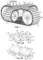
- FIG. 1is a perspective view of a two-axis modular belt conveyor embodying features of the invention.
- FIGS. 2A and 2Bare bottom and top views of pairs of connected belt modules used to build a conveyor belt as in FIG. 1 .
- FIG. 3Ais an isometric view of a portion of a two-axis conveyor belt as in FIG. 1 showing translation of some of the belt modules along a first axis
- FIG. 3Bis an isometric view of that portion showing translation of some of the belt modules along a second axis perpendicular to the first axis.
- FIG. 4is an isometric view of another version of a pair of belt modules usable in a conveyor belt as in FIG. 1 .
- FIGS. 5A and 5Bare bottom and top views of yet another version of a pair of belt modules having hook-shaped hinge elements at all four sides and that are usable in a conveyor belt as in FIG. 1 .
- FIG. 6is an isometric view of a wire-frame version of a belt module usable in a conveyor belt as in FIG. 1 .
- FIG. 7is a view of the wire frame of two belt modules as in FIG. 6 with the platform removed for clarity.
- FIG. 8is a top plan view of a punched flat metal sheet used to make a sheet-metal belt module usable in a conveyor belt as in FIG. 1 .
- FIGS. 9A and 9Bare bottom and top views of the base of a sheet-metal belt module made from the sheet of FIG. 8 .
- FIG. 10is an exploded view of the entire sheet-metal belt module including the base of FIGS. 9A and 9B and a snap-on or molded-on platform.
- FIG. 11is a partly exploded isometric view of a conveyor using a conveyor belt as in FIG. 1 driven by motorized-roller-driven drive wheels.
- FIG. 12is an isometric view of a conveyor frame for a conveyor as in FIG. 11 .
- FIG. 13is a top plan view of another version of a conveyor as in FIG. 11 with one first axis and two second axes.
- FIG. 14is an isometric view of a portion of a grid sorter using two-axis conveyors as in FIG. 1 .
- the modular conveyor belt 20is constructed of rectangular belt modules 22 arranged in rows and columns. In the examples shown the rectangular modules 22 are square, but they could be non-square rectangles.
- the conveyor beltincludes a first belt loop 24 arranged to advance along a first path and a second belt loop 26 arranged to advance along a second path perpendicular to the first path at a union 28 of the first and second belt loops.
- the rows 30 R, 31 R of belt modulesextend across the loops' widths; the columns 30 C, 31 C extend the lengths of the loops.
- the belt modules 22 at the union 28 of the two belt loops 24 , 26are shared by the two loops.
- the rows 30 R of the first belt loop 24are the columns 31 C of the second belt loop 26
- the columns 30 C of the first belt loopare the rows 31 R of the second belt loop.
- a lower portion 32 of the second belt loop 26lies within the first belt loop 24 .
- FIGS. 2A and 2BOne version of a belt module 22 that enables the sharing of modules by both belt loops at the union is shown in FIGS. 2A and 2B connected to an identical belt module 22 ′.
- the module 22includes a rectangular platform 34 having a first pair of adjacent sides 36 , 37 , a second pair of adjacent sides 38 , 39 , and a square top surface 40 .
- First hinge elements 42extend downward from the platform 34 along the first pair of adjacent sides 36 , 37 .
- Second hinge elements 44extend downward from the module along the second pair of adjacent sides 38 , 39 .
- the first hinge elements 42are hook-shaped with a shank 43 that extends down from the bottom of the platform through an outward bend 45 to a tip end 56 .
- An upwardly open throat 47is formed between the shank 43 and the tip end 56 .
- the throat 47forms an elongated channel 46 that extends parallel to its associated side 36 , 37 of the platform 34 .
- the second hinge elements 44form pins 48 .
- Adjacent modules 22 , 22 ′are interconnected by mating a first hinge element 42 of one module 22 ′ with a second hinge element 44 of another module 22 at a hinge joint 49 .
- the pins 48which extend parallel to the associated sides 38 , 39 , are generally circular in cross section with a radius that equals or is slightly less than the radius of curvature of the bed 50 of the channels 46 of the hook-shaped hinge elements 42 .
- the pins 48nestle in the channels 46 concentric with the centers of curvatures of the channel beds 50 and define an articulation axis about which the belt articulates when rounding reversing wheels, such as drive and idler sprockets.
- the channels 46are open at both ends so that the pins 48 , serving as slide members, can slide along the channels 46 of adjacent modules.
- the pins 48are attached at opposite ends to the platform 34 by arms 52 , forming a gap 54 bounded by the pin, the arms, and the platform.
- the gap 54extends the articulation range of two adjacent belt modules 22 , 22 ′ by providing clearance for the tip end 56 of the interconnected hook-shaped hinge element 42 as the pin 48 rotates in the channel 46 .
- the sides 58 of the tip end 56 of the laterally elongated hook-shaped hinge elements 42are tapered to help guide the tip end into the gap 54 .
- the shared rows and columns of belt modules 22 in the union 28 of the two orthogonal belt loopscan be translated along perpendicular axes 60 , 61 in the direction of the moving belt loop.
- only one belt loop at a timecan be moved.
- the pins 48 on one side of the loopslide through the aligned channels of the stationary belt loop, and the hook-shaped hinge elements on the other side of the advancing belt loop slide along the pins 48 on the stationary belt loop.
- the belt modules 62 in FIG. 4include an additional feature absent in the modules of FIGS. 2A and 2B .
- Half rounds 64protrude outward of two adjacent sides 66 , 67 of the platform 65 .
- Half pipes 68open at both ends are recessed into the other two sides 70 , 71 .
- the half pipes 68 of one module 62receive the half rounds of an adjacent module at a hinge joint 69 .
- the half pipes 68 and half rounds 64help resist jams as the modules 62 slide past each other.
- FIGS. 5A and 5BAnother version of a belt module usable in a conveyor belt as in FIG. 1 is shown in FIGS. 5A and 5B .
- this belt module 72the pin of the second hinge elements of the modules in FIGS. 2A, 2B, and 4 is replaced by a hook-shaped appendage.
- the hook-shaped first hinge elements 74 along one pair of adjacent sides of the module 72have channels 76 that open upward.
- the hook-shaped hinge elements 78 on the other two adjacent sideshave channels 80 that open inward.
- the arc length of the upwardly open hooks 74is longer than the arc length of the inwardly open hooks 78 .
- the bend 82 and tip end 84 of the shorter hooks 78serve as slide members of the modules 72 .
- the curvature and thickness of the hooksare complementary. They engage in a mating relationship that allows the hooks to slide along each other and to rotate smoothly.
- the belt modules described thus farcan be made of injection-molded thermoplastic or molded metal.
- the belt module 86 of FIGS. 6 and 7is made of a wire frame 88 to which a platform 90 can be overmolded or otherwise attached.
- the wire frame 88 of the module in FIG. 6forms hooks 92 on two adjacent sides and pins 94 on the other two sides.
- pins 94 of one moduleare received in channels 96 formed by the hooks 92 of an adjacent module as for the modules of FIGS. 2A and 2B .
- the belt module 100 of FIG. 10has a sheet-metal frame 102 .
- the frame 102also shown in FIGS. 9A and 9B , is formed from a flat metal sheet 104 as shown in FIG. 8 . Gaps 106 and a central hole 114 are cut in the sheet.
- the flat sheet 104is bent at bend lines 108 to form the sheet-metal frame 102 .
- a pre-formed platform 110has a bottom boss 112 with a lower lip 113 . Slits 115 give the boss 112 a spring effect so that it can be snapped into the hole 114 in the center of the frame 102 and retained by the lower lip 113 .
- a platformmay be overmolded onto the frame 102 .
- Hook-shaped hinge elements 116 and pin-type hinge elements 118are formed along opposite pairs of adjacent sides of the sheet-metal frame 102 .
- FIGS. 11 and 12show the components of a conveyor using a two-axis conveyor belt as in FIG. 1 .
- FIG. 11shows the belt 20 and drive components without a conveyor frame 120 , which is shown separately in FIG. 12 for drawing clarity.
- the first belt loop 24 of the modular conveyor belt 20is trained around two reversing wheels 122 , 123 .
- One of the reversing wheelscan be a drive wheel and the other an idler wheel, or both can be drive wheels.
- the second belt loop 26is trained around a pair of reversing wheels 124 , 125 .
- the reversing wheels 122 , 123 , 124 , 125have peripheral drive structure that engages drive structure on the undersides of the belt 20 to drive the first and second belt loops 24 , 26 along first and second paths perpendicular to each other.
- the reversing drive wheelsare shown driven by motorized rollers 126 mounted tightly in hollows 128 in the hubs 130 of the wheels 124 . But the wheels could alternatively be driven by external motors via gear trains or by belts and pulleys as is common in the conveying industry.
- the diameter of the reversing wheels 122 , 123 for the first belt loop 24is greater than the diameter of the reversing wheels 124 , 125 for the second belt loop 26 .
- the belt-loop pathsare defined by the conveyor frame 120 of FIG. 12 .
- the frame 120includes a cruciform upper carryway 132 supporting the two belt loops 24 , 26 along upper carryway segments of the conveying paths of the two loops.
- the frame 120also includes a first return surface 134 that supports the first belt loop 24 in a lower return segment of the first path.
- a portion of a second return surface 136 for the second belt loop 26 in a lower return segment of the second pathlies between the union 28 of the two belt loops at the middle of the cruciform carryway 132 and a portion of the first return surface 134 .
- the two pathsinclude reversing segments around the reversing wheels between the upper carryway segments and the lower return segments.
- the supporting return surfaces 134 , 136transition into cover portions 138 of the conveyor frame 120 around the reversing wheels 122 , 123 , 124 , 125 to maintain the belt loops 24 , 26 in engagement with the wheels.
- the cover portions 138are continuous with the corresponding return surfaces 134 , 136 .
- Side walls 140 bounding the conveyor path segmentsmaintain the belt loops in alignment.
- Position sensors 142are used to sense when packages are in the union 28 . If a package conveyed into the union 28 in the first belt loop 24 requires a 90° change in direction, the position sensor's signal is sent to a controller (not shown) that controls the loop drive motors to stop the first belt loop and start the second belt loop 26 to convey the package in the desired discharge direction.
- FIG. 13Another version of a conveyor belt is shown in FIG. 13 .
- the belt 144has a single long loop 146 and two cross loops 148 , 150 orthogonal to the long loop.
- the cross loops 148 , 150intersect the long loop 146 at unions 152 , 154 on the carryway.
- the belt 144is one example indicating that belts with different numbers of first and second groups of orthogonal belt loops can be constructed.
- the two-axis belt conveyors of FIGS. 11 and 12are shown in a portion of a grid sorter 160 in FIG. 14 .
- the grid sorteris constructed of series of bidirectional conveyors 162 , such as belt conveyors or roller conveyors, arranged in a grid of north-south conveyor lines 164 and east-west conveyor lines 166 .
- the north-south conveyor lines 164intersect the east-west conveyor lines 166 at right angles. All the bidirectional conveyors 162 in the north-south conveyor lines 164 are parallel, and all the bidirectional conveyors in the east-west conveyor lines are parallel.
- Two-axis belt conveyors 168are disposed at the intersections of the north-south and east-west conveyor lines 164 , 168 .
- the two-axis belt conveyors 168transfer packages to and receive packages from the bidirectional conveyors 162 over the four sides of the two-axis conveyors.
- transfer platforms 170can be interposed between the sides of the two-axis belt conveyors 168 and the bidirectional conveyors 162 .
- Some of the two-axis belt conveyorscould have a chute or elevating conveyor, rather than a horizontal bidirectional conveyor, at one or more sides to deliver packages to or receive packages from a grid sorter layer above or below in a three-dimensional, multi-layer grid sorter.
- the two-axis belt conveyorcan also be used to shift packages on the carryway. For example, a package conveyed into the union of the two belt loops on the carryway on a first belt loop can be shifted laterally across the first belt loop by stopping the first belt loop, running the second belt loop to shift the package across the first belt loop, stopping the second belt loop when the shift is complete, and running the first belt loop to transfer the laterally shifted package to a discharge conveyor.
Landscapes
- Engineering & Computer Science (AREA)
- Mechanical Engineering (AREA)
- Structure Of Belt Conveyors (AREA)
Abstract
Description
Claims (22)
Priority Applications (1)
| Application Number | Priority Date | Filing Date | Title |
|---|---|---|---|
| US17/421,956US11505409B2 (en) | 2019-02-06 | 2020-01-29 | Two-axis modular belt and conveyor |
Applications Claiming Priority (3)
| Application Number | Priority Date | Filing Date | Title |
|---|---|---|---|
| US201962801690P | 2019-02-06 | 2019-02-06 | |
| US17/421,956US11505409B2 (en) | 2019-02-06 | 2020-01-29 | Two-axis modular belt and conveyor |
| PCT/US2020/015560WO2020163129A1 (en) | 2019-02-06 | 2020-01-29 | Two- axis modular belt and conveyor |
Publications (2)
| Publication Number | Publication Date |
|---|---|
| US20220119198A1 US20220119198A1 (en) | 2022-04-21 |
| US11505409B2true US11505409B2 (en) | 2022-11-22 |
Family
ID=71946993
Family Applications (1)
| Application Number | Title | Priority Date | Filing Date |
|---|---|---|---|
| US17/421,956ActiveUS11505409B2 (en) | 2019-02-06 | 2020-01-29 | Two-axis modular belt and conveyor |
Country Status (4)
| Country | Link |
|---|---|
| US (1) | US11505409B2 (en) |
| EP (1) | EP3880586A4 (en) |
| CN (1) | CN113272235B (en) |
| WO (1) | WO2020163129A1 (en) |
Families Citing this family (1)
| Publication number | Priority date | Publication date | Assignee | Title |
|---|---|---|---|---|
| US11958694B2 (en) | 2022-03-11 | 2024-04-16 | Laitram, L.L.C. | Magnetic XY sorting conveyor |
Citations (18)
| Publication number | Priority date | Publication date | Assignee | Title |
|---|---|---|---|---|
| US853129A (en) | 1907-03-19 | 1907-05-07 | Alfred L Simpson | Traveling platform, grate, or surface. |
| US3451526A (en) | 1967-03-03 | 1969-06-24 | John Fernandez | Conveyor systems |
| US4882901A (en) | 1980-11-26 | 1989-11-28 | The Laitram Corporation | Detachable link chain |
| JPH07267346A (en) | 1994-03-28 | 1995-10-17 | Kinugawa Rubber Ind Co Ltd | Crossover type belt conveyor |
| US6568522B1 (en) | 2002-05-16 | 2003-05-27 | The Laitram Corporation | Accumulation system |
| EP1468943A2 (en) | 2003-04-15 | 2004-10-20 | Integral Technologies, Inc. | Food processing belts and other conveyances manufactured from conductive loaded resin-based materials |
| US20050065642A1 (en) | 2003-08-29 | 2005-03-24 | Siemens Aktiengesellschaft | Transport system, in particular an airport luggage transport system, and a controller for a transport system |
| US6966742B2 (en) | 2002-10-03 | 2005-11-22 | Shinko Electric Industries Co., Ltd. | Work arrangement apparatus |
| US7073651B2 (en)* | 2003-07-30 | 2006-07-11 | Laitram, L.L.C. | Modular mat gravity-advance roller conveyor |
| US7147097B2 (en) | 2004-09-30 | 2006-12-12 | Laitram, L.L.C. | Transverse-roller-belt sorter with automated guide |
| US7306086B2 (en)* | 2004-09-27 | 2007-12-11 | Laitram, L.L.C. | Sorting system using a roller-top conveyor belt |
| US7527143B2 (en) | 2006-11-03 | 2009-05-05 | Habasit Ag | Conveyor belt with intermodular supported rollers |
| US7571701B1 (en)* | 2008-02-01 | 2009-08-11 | Gm Global Technology Operations, Inc. | Camshaft cover with integrated intake manifold |
| US8939279B2 (en)* | 2013-01-08 | 2015-01-27 | Solus Industrial Innovations, Llc | Modular conveying systems and methods |
| US9038810B2 (en)* | 2013-03-12 | 2015-05-26 | Fives Intralogistics Corp. | Singulator conveyor |
| US20160185529A1 (en) | 2014-12-31 | 2016-06-30 | Prince Castle LLC | Sprocket driven conveyor belt link and conveyor belt assembly |
| US9889992B1 (en) | 2015-05-13 | 2018-02-13 | Prince Castle LLC | Conveyor belt slat |
| US9908708B1 (en) | 2015-05-13 | 2018-03-06 | Prince Castle LLC | Conveyor belt link with coupling mechanism |
Family Cites Families (5)
| Publication number | Priority date | Publication date | Assignee | Title |
|---|---|---|---|---|
| US8863944B2 (en)* | 2012-02-20 | 2014-10-21 | Laitram, L.L.C. | Abrasion resistant conveyor belt |
| US8905228B2 (en)* | 2013-02-04 | 2014-12-09 | Laitram, L.L.C. | Self-supporting conveyor belt |
| NL2011933C2 (en)* | 2013-12-10 | 2015-06-11 | Rexnord Flattop Europe Bv | Coupling of conveyor belt modules. |
| US10604345B2 (en)* | 2016-06-15 | 2020-03-31 | Laitram, L.L.C. | Flat-top side-drive modular conveyor belt |
| CN109140065A (en)* | 2018-09-06 | 2019-01-04 | 四川川油工程技术勘察设计有限公司 | A kind of petroleum transportation equipment easy to clean |
- 2020
- 2020-01-29WOPCT/US2020/015560patent/WO2020163129A1/ennot_activeCeased
- 2020-01-29EPEP20752338.2Apatent/EP3880586A4/enactivePending
- 2020-01-29USUS17/421,956patent/US11505409B2/enactiveActive
- 2020-01-29CNCN202080008441.XApatent/CN113272235B/enactiveActive
Patent Citations (18)
| Publication number | Priority date | Publication date | Assignee | Title |
|---|---|---|---|---|
| US853129A (en) | 1907-03-19 | 1907-05-07 | Alfred L Simpson | Traveling platform, grate, or surface. |
| US3451526A (en) | 1967-03-03 | 1969-06-24 | John Fernandez | Conveyor systems |
| US4882901A (en) | 1980-11-26 | 1989-11-28 | The Laitram Corporation | Detachable link chain |
| JPH07267346A (en) | 1994-03-28 | 1995-10-17 | Kinugawa Rubber Ind Co Ltd | Crossover type belt conveyor |
| US6568522B1 (en) | 2002-05-16 | 2003-05-27 | The Laitram Corporation | Accumulation system |
| US6966742B2 (en) | 2002-10-03 | 2005-11-22 | Shinko Electric Industries Co., Ltd. | Work arrangement apparatus |
| EP1468943A2 (en) | 2003-04-15 | 2004-10-20 | Integral Technologies, Inc. | Food processing belts and other conveyances manufactured from conductive loaded resin-based materials |
| US7073651B2 (en)* | 2003-07-30 | 2006-07-11 | Laitram, L.L.C. | Modular mat gravity-advance roller conveyor |
| US20050065642A1 (en) | 2003-08-29 | 2005-03-24 | Siemens Aktiengesellschaft | Transport system, in particular an airport luggage transport system, and a controller for a transport system |
| US7306086B2 (en)* | 2004-09-27 | 2007-12-11 | Laitram, L.L.C. | Sorting system using a roller-top conveyor belt |
| US7147097B2 (en) | 2004-09-30 | 2006-12-12 | Laitram, L.L.C. | Transverse-roller-belt sorter with automated guide |
| US7527143B2 (en) | 2006-11-03 | 2009-05-05 | Habasit Ag | Conveyor belt with intermodular supported rollers |
| US7571701B1 (en)* | 2008-02-01 | 2009-08-11 | Gm Global Technology Operations, Inc. | Camshaft cover with integrated intake manifold |
| US8939279B2 (en)* | 2013-01-08 | 2015-01-27 | Solus Industrial Innovations, Llc | Modular conveying systems and methods |
| US9038810B2 (en)* | 2013-03-12 | 2015-05-26 | Fives Intralogistics Corp. | Singulator conveyor |
| US20160185529A1 (en) | 2014-12-31 | 2016-06-30 | Prince Castle LLC | Sprocket driven conveyor belt link and conveyor belt assembly |
| US9889992B1 (en) | 2015-05-13 | 2018-02-13 | Prince Castle LLC | Conveyor belt slat |
| US9908708B1 (en) | 2015-05-13 | 2018-03-06 | Prince Castle LLC | Conveyor belt link with coupling mechanism |
Non-Patent Citations (1)
| Title |
|---|
| Supplementary European Search Report, European Patent Application No. 20752338.2, dated Jul. 8, 2022. |
Also Published As
| Publication number | Publication date |
|---|---|
| EP3880586A4 (en) | 2022-08-10 |
| WO2020163129A1 (en) | 2020-08-13 |
| EP3880586A1 (en) | 2021-09-22 |
| CN113272235A (en) | 2021-08-17 |
| US20220119198A1 (en) | 2022-04-21 |
| CN113272235B (en) | 2023-09-15 |
Similar Documents
| Publication | Publication Date | Title |
|---|---|---|
| US4051949A (en) | Conveyor system | |
| EP3283408B1 (en) | Conveyor system with transfer belts | |
| US20100089724A1 (en) | Conveyor | |
| US8678180B2 (en) | Modular conveyor belt with extended raised ribs | |
| CN102666322B (en) | Self-clearing conveyor transfer system and transfer plate | |
| US6644466B2 (en) | Platform-top radius belt and modules | |
| US8763787B2 (en) | Conveyor | |
| KR20140035304A (en) | Conveyor, belt, and module having multi-directional wheels | |
| MX2007001458A (en) | Conveyor apparatus and system. | |
| US8371436B2 (en) | Conveyor provided with side guard, and side guard element | |
| CN101687597B (en) | Module for a modular belt and a driving sprocket for easy cleaning | |
| US9663298B2 (en) | Conveyor belt module with shaped bottom surface | |
| US6105755A (en) | Curved conveyor section | |
| US11505409B2 (en) | Two-axis modular belt and conveyor | |
| EP3825261B1 (en) | A conveyor and a conveying system | |
| US4709799A (en) | Arrangement for orienting articles on a conveyor | |
| US5915521A (en) | Random indexing and lifting apparatus |
Legal Events
| Date | Code | Title | Description |
|---|---|---|---|
| AS | Assignment | Owner name:LAITRAM, L.L.C., LOUISIANA Free format text:ASSIGNMENT OF ASSIGNORS INTEREST;ASSIGNOR:RAGAN, BRYANT G.;REEL/FRAME:056805/0546 Effective date:20190131 | |
| FEPP | Fee payment procedure | Free format text:ENTITY STATUS SET TO UNDISCOUNTED (ORIGINAL EVENT CODE: BIG.); ENTITY STATUS OF PATENT OWNER: LARGE ENTITY | |
| STPP | Information on status: patent application and granting procedure in general | Free format text:DOCKETED NEW CASE - READY FOR EXAMINATION | |
| STPP | Information on status: patent application and granting procedure in general | Free format text:NOTICE OF ALLOWANCE MAILED -- APPLICATION RECEIVED IN OFFICE OF PUBLICATIONS | |
| STPP | Information on status: patent application and granting procedure in general | Free format text:AWAITING TC RESP., ISSUE FEE NOT PAID | |
| STPP | Information on status: patent application and granting procedure in general | Free format text:PUBLICATIONS -- ISSUE FEE PAYMENT VERIFIED | |
| STPP | Information on status: patent application and granting procedure in general | Free format text:WITHDRAW FROM ISSUE AWAITING ACTION | |
| STPP | Information on status: patent application and granting procedure in general | Free format text:AWAITING TC RESP., ISSUE FEE NOT PAID | |
| STPP | Information on status: patent application and granting procedure in general | Free format text:NON FINAL ACTION MAILED | |
| STPP | Information on status: patent application and granting procedure in general | Free format text:RESPONSE TO NON-FINAL OFFICE ACTION ENTERED AND FORWARDED TO EXAMINER | |
| STCF | Information on status: patent grant | Free format text:PATENTED CASE |