US11505084B2 - Battery placement for electric refuse vehicle - Google Patents
Battery placement for electric refuse vehicleDownload PDFInfo
- Publication number
- US11505084B2 US11505084B2US17/362,601US202117362601AUS11505084B2US 11505084 B2US11505084 B2US 11505084B2US 202117362601 AUS202117362601 AUS 202117362601AUS 11505084 B2US11505084 B2US 11505084B2
- Authority
- US
- United States
- Prior art keywords
- frame member
- left frame
- right frame
- refuse vehicle
- battery cells
- Prior art date
- Legal status (The legal status is an assumption and is not a legal conclusion. Google has not performed a legal analysis and makes no representation as to the accuracy of the status listed.)
- Active
Links
Images


Classifications
- B—PERFORMING OPERATIONS; TRANSPORTING
- B60—VEHICLES IN GENERAL
- B60L—PROPULSION OF ELECTRICALLY-PROPELLED VEHICLES; SUPPLYING ELECTRIC POWER FOR AUXILIARY EQUIPMENT OF ELECTRICALLY-PROPELLED VEHICLES; ELECTRODYNAMIC BRAKE SYSTEMS FOR VEHICLES IN GENERAL; MAGNETIC SUSPENSION OR LEVITATION FOR VEHICLES; MONITORING OPERATING VARIABLES OF ELECTRICALLY-PROPELLED VEHICLES; ELECTRIC SAFETY DEVICES FOR ELECTRICALLY-PROPELLED VEHICLES
- B60L53/00—Methods of charging batteries, specially adapted for electric vehicles; Charging stations or on-board charging equipment therefor; Exchange of energy storage elements in electric vehicles
- B60L53/80—Exchanging energy storage elements, e.g. removable batteries
- B—PERFORMING OPERATIONS; TRANSPORTING
- B65—CONVEYING; PACKING; STORING; HANDLING THIN OR FILAMENTARY MATERIAL
- B65F—GATHERING OR REMOVAL OF DOMESTIC OR LIKE REFUSE
- B65F3/00—Vehicles particularly adapted for collecting refuse
- B65F3/02—Vehicles particularly adapted for collecting refuse with means for discharging refuse receptacles thereinto
- B—PERFORMING OPERATIONS; TRANSPORTING
- B60—VEHICLES IN GENERAL
- B60K—ARRANGEMENT OR MOUNTING OF PROPULSION UNITS OR OF TRANSMISSIONS IN VEHICLES; ARRANGEMENT OR MOUNTING OF PLURAL DIVERSE PRIME-MOVERS IN VEHICLES; AUXILIARY DRIVES FOR VEHICLES; INSTRUMENTATION OR DASHBOARDS FOR VEHICLES; ARRANGEMENTS IN CONNECTION WITH COOLING, AIR INTAKE, GAS EXHAUST OR FUEL SUPPLY OF PROPULSION UNITS IN VEHICLES
- B60K1/00—Arrangement or mounting of electrical propulsion units
- B60K1/04—Arrangement or mounting of electrical propulsion units of the electric storage means for propulsion
- B—PERFORMING OPERATIONS; TRANSPORTING
- B60—VEHICLES IN GENERAL
- B60L—PROPULSION OF ELECTRICALLY-PROPELLED VEHICLES; SUPPLYING ELECTRIC POWER FOR AUXILIARY EQUIPMENT OF ELECTRICALLY-PROPELLED VEHICLES; ELECTRODYNAMIC BRAKE SYSTEMS FOR VEHICLES IN GENERAL; MAGNETIC SUSPENSION OR LEVITATION FOR VEHICLES; MONITORING OPERATING VARIABLES OF ELECTRICALLY-PROPELLED VEHICLES; ELECTRIC SAFETY DEVICES FOR ELECTRICALLY-PROPELLED VEHICLES
- B60L50/00—Electric propulsion with power supplied within the vehicle
- B60L50/50—Electric propulsion with power supplied within the vehicle using propulsion power supplied by batteries or fuel cells
- B60L50/60—Electric propulsion with power supplied within the vehicle using propulsion power supplied by batteries or fuel cells using power supplied by batteries
- B60L50/64—Constructional details of batteries specially adapted for electric vehicles
- B—PERFORMING OPERATIONS; TRANSPORTING
- B60—VEHICLES IN GENERAL
- B60L—PROPULSION OF ELECTRICALLY-PROPELLED VEHICLES; SUPPLYING ELECTRIC POWER FOR AUXILIARY EQUIPMENT OF ELECTRICALLY-PROPELLED VEHICLES; ELECTRODYNAMIC BRAKE SYSTEMS FOR VEHICLES IN GENERAL; MAGNETIC SUSPENSION OR LEVITATION FOR VEHICLES; MONITORING OPERATING VARIABLES OF ELECTRICALLY-PROPELLED VEHICLES; ELECTRIC SAFETY DEVICES FOR ELECTRICALLY-PROPELLED VEHICLES
- B60L50/00—Electric propulsion with power supplied within the vehicle
- B60L50/50—Electric propulsion with power supplied within the vehicle using propulsion power supplied by batteries or fuel cells
- B60L50/60—Electric propulsion with power supplied within the vehicle using propulsion power supplied by batteries or fuel cells using power supplied by batteries
- B60L50/66—Arrangements of batteries
- B—PERFORMING OPERATIONS; TRANSPORTING
- B65—CONVEYING; PACKING; STORING; HANDLING THIN OR FILAMENTARY MATERIAL
- B65F—GATHERING OR REMOVAL OF DOMESTIC OR LIKE REFUSE
- B65F3/00—Vehicles particularly adapted for collecting refuse
- B—PERFORMING OPERATIONS; TRANSPORTING
- B65—CONVEYING; PACKING; STORING; HANDLING THIN OR FILAMENTARY MATERIAL
- B65F—GATHERING OR REMOVAL OF DOMESTIC OR LIKE REFUSE
- B65F3/00—Vehicles particularly adapted for collecting refuse
- B65F3/14—Vehicles particularly adapted for collecting refuse with devices for charging, distributing or compressing refuse in the interior of the tank of a refuse vehicle
- B—PERFORMING OPERATIONS; TRANSPORTING
- B60—VEHICLES IN GENERAL
- B60Y—INDEXING SCHEME RELATING TO ASPECTS CROSS-CUTTING VEHICLE TECHNOLOGY
- B60Y2200/00—Type of vehicle
- B60Y2200/10—Road Vehicles
- B60Y2200/14—Trucks; Load vehicles, Busses
- B60Y2200/144—Garbage trucks, e.g. refuse trucks
- Y—GENERAL TAGGING OF NEW TECHNOLOGICAL DEVELOPMENTS; GENERAL TAGGING OF CROSS-SECTIONAL TECHNOLOGIES SPANNING OVER SEVERAL SECTIONS OF THE IPC; TECHNICAL SUBJECTS COVERED BY FORMER USPC CROSS-REFERENCE ART COLLECTIONS [XRACs] AND DIGESTS
- Y02—TECHNOLOGIES OR APPLICATIONS FOR MITIGATION OR ADAPTATION AGAINST CLIMATE CHANGE
- Y02T—CLIMATE CHANGE MITIGATION TECHNOLOGIES RELATED TO TRANSPORTATION
- Y02T10/00—Road transport of goods or passengers
- Y02T10/60—Other road transportation technologies with climate change mitigation effect
- Y02T10/70—Energy storage systems for electromobility, e.g. batteries
- Y—GENERAL TAGGING OF NEW TECHNOLOGICAL DEVELOPMENTS; GENERAL TAGGING OF CROSS-SECTIONAL TECHNOLOGIES SPANNING OVER SEVERAL SECTIONS OF THE IPC; TECHNICAL SUBJECTS COVERED BY FORMER USPC CROSS-REFERENCE ART COLLECTIONS [XRACs] AND DIGESTS
- Y02—TECHNOLOGIES OR APPLICATIONS FOR MITIGATION OR ADAPTATION AGAINST CLIMATE CHANGE
- Y02T—CLIMATE CHANGE MITIGATION TECHNOLOGIES RELATED TO TRANSPORTATION
- Y02T10/00—Road transport of goods or passengers
- Y02T10/60—Other road transportation technologies with climate change mitigation effect
- Y02T10/7072—Electromobility specific charging systems or methods for batteries, ultracapacitors, supercapacitors or double-layer capacitors
- Y—GENERAL TAGGING OF NEW TECHNOLOGICAL DEVELOPMENTS; GENERAL TAGGING OF CROSS-SECTIONAL TECHNOLOGIES SPANNING OVER SEVERAL SECTIONS OF THE IPC; TECHNICAL SUBJECTS COVERED BY FORMER USPC CROSS-REFERENCE ART COLLECTIONS [XRACs] AND DIGESTS
- Y02—TECHNOLOGIES OR APPLICATIONS FOR MITIGATION OR ADAPTATION AGAINST CLIMATE CHANGE
- Y02W—CLIMATE CHANGE MITIGATION TECHNOLOGIES RELATED TO WASTEWATER TREATMENT OR WASTE MANAGEMENT
- Y02W30/00—Technologies for solid waste management
- Y02W30/10—Waste collection, transportation, transfer or storage, e.g. segregated refuse collecting, electric or hybrid propulsion
Definitions
- Refuse vehiclescollect a wide variety of waste, trash, and other material from residences and businesses. Operators of the refuse vehicles transport the material from various waste receptacles within a municipality to a storage or processing facility (e.g., a landfill, an incineration facility, a recycling facility, etc.).
- a storage or processing facilitye.g., a landfill, an incineration facility, a recycling facility, etc.
- One embodimentrelates to a refuse vehicle including a chassis, a body, and a plurality of battery cells.
- the chassisincludes a right frame member and a left frame member spaced apart in a lateral direction and extending lengthwise in a longitudinal direction.
- the bodyis coupled to the chassis.
- the plurality of battery cellsare longitudinally disposed along the chassis, positioned between the right frame member and the left frame member.
- a refuse vehicleincluding a chassis, a body, and a plurality of battery cells.
- the bodyis coupled to the chassis, and includes a right body frame member and a left body frame member spaced apart in a lateral direction and extending lengthwise in a longitudinal direction.
- the plurality of battery cellsare longitudinally disposed along the body, positioned between the right body frame member and the left body frame member.
- a refuse vehicleincluding a chassis, a body, and a plurality of battery cells.
- the chassisincludes a right frame member and a left frame member spaced apart in a lateral direction and extending lengthwise in a longitudinal direction.
- the bodyis coupled to the chassis and includes a right body frame member and a left body frame member spaced apart in the lateral direction and extending lengthwise in the longitudinal direction.
- the plurality of battery cellsare longitudinally disposed along the chassis and the body, positioned between both (1) the right frame member and the left frame member, and (2) the right body frame member and the left body frame member.
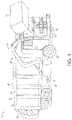
- FIG. 1is a perspective view of a refuse vehicle, according to an exemplary embodiment.
- FIG. 2is a side section view of a battery pod assembly, according to an exemplary embodiment.
- FIG. 3is a side view of the refuse vehicle of FIG. 1 having a bottom mounted battery pod, according to an exemplary embodiment.
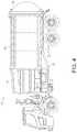
- FIG. 4is a side view of the refuse vehicle of FIG. 1 having a top mounted battery pod, according to an exemplary embodiment.
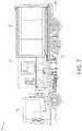
- FIG. 5is a side view of the refuse container of FIG. 1 having a centrally mounted battery pod, according to an exemplary embodiment.
- FIG. 6is a perspective view of the refuse container of FIG. 1 having a tailgate mounted battery pod, according to an exemplary embodiment.
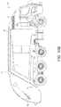
- FIG. 7is a side view of the refuse container of FIG. 1 having a frame mounted battery pod, according to an exemplary embodiment.
- FIGS. 8A-9Bare the refuse vehicle of FIG. 1 having multiple battery pods, according to several exemplary embodiments.
- FIGS. 10A-10Bare the refuse vehicle of FIG. 1 having a top mounted battery pod, according to several exemplary embodiments.
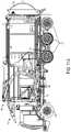
- FIG. 11Ais a side view of the refuse vehicle of FIG. 1 having batteries positioned between chassis frame rails of the refuse vehicle, according to an exemplary embodiment.
- FIG. 11Bis a perspective view of the refuse vehicle of FIG. 1 having batteries positioned between the chassis frame rails of the refuse vehicle, according to an exemplary embodiment.
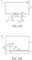
- FIG. 11Cis a diagram of a battery positioned between C-shaped chassis frame rails of a refuse vehicle, according to an exemplary embodiment.
- FIG. 11Dis a diagram of a battery positioned between L-shaped chassis frame rails of a refuse vehicle, according to an exemplary embodiment.
- FIG. 12Ais a side view of the refuse vehicle of FIG. 1 having batteries positioned between longitudinal body frame members above a chassis of the refuse vehicle, according to an exemplary embodiment.
- FIG. 12Bis a perspective view of the refuse vehicle of FIG. 1 having batteries positioned between the longitudinal body frame members above the chassis of the refuse vehicle, according to an exemplary embodiment.
- FIG. 12Cis a diagram of a portion of the refuse vehicle of FIGS. 12A-12B with batteries positioned above the chassis beneath a floor surface of the body, according to an exemplary embodiment.
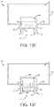
- FIG. 13Ais a diagram of a battery positioned between both chassis frame rails and body frame rails of a refuse vehicle, according to an exemplary embodiment.
- FIG. 13Bis a diagram of stacked batteries positioned between both chassis frame rails and body frame rails of a refuse vehicle, according to an exemplary embodiment.
- FIG. 13Cis a diagram of a battery positioned between body frame rails of a refuse vehicle, above a chassis of the refuse vehicle, according to an exemplary embodiment.
- FIG. 13Dis a diagram of a side view of a body and frame of a refuse vehicle, with batteries extending into a space of the body, according to an exemplary embodiment.
- FIG. 13Eis a diagram of a body and frame of a refuse vehicle, with batteries extending into a space of the body, according to an exemplary embodiment.
- FIG. 13Fis a diagram of a body and frame of a refuse vehicle, with batteries extending into a space of the body and between chassis frame rails of the refuse vehicle, according to an exemplary embodiment.
- a battery pod assembly for a refuse vehicleis disclosed herein.
- the battery pod assembly of the present disclosureprovides many advantages over conventional systems.
- the battery pod assemblymay include various stress mitigation devices to mitigate mechanical stress (e.g., tensile stress, compressive stress, shear stress, cyclic stress, etc.), thermal stress (e.g., thermal cycling, thermal events, etc.), and/or physical ingress (e.g., water ingress, debris ingress, chemical ingress, etc.) on the battery pod assembly and components thereof.
- the battery pod assemblymay be positioned in various locations on the refuse vehicle such that the battery pod assembly is readily accessible for regular maintenance.
- components of the battery pod assemblymay be modular such that the components can be swapped out or upgraded. For example, a battery cell may be upgraded to future battery cell chemistries not yet available.
- the refuse vehicleincludes batteries positioned in a longitudinal direction between chassis frame rails of the refuse vehicle, between body frame rails of the refuse vehicle, or between both the chassis frame rails of the refuse vehicle and the body frame rails of the refuse vehicle.
- the batteriescan be the battery pod assembly and may include housings.
- the batteriesmay be stacked in a lateral or vertical direction and positioned between the chassis frame rails, between the body frame rails, or between both the chassis and the body frame rails.
- the chassis frame rails and the body frame railsdefine a space within which the batteries can be positioned.
- the batteriescan be fastened or coupled with the body frame rails and/or the chassis frame rails depending on configuration and positioning.
- the batteriescan be hung from an underside of the body of the refuse vehicle.
- a vehicleshown as refuse vehicle 10 (e.g., a garbage truck, a waste collection truck, a sanitation truck, a recycling truck, etc.), is configured as a front-loading refuse truck.
- the refuse vehicle 10is configured as a side-loading refuse truck or a rear-loading refuse truck.
- the vehicleis another type of vehicle (e.g., a skid-loader, a telehandler, a plow truck, a boom lift, etc.).
- FIG. 10e.g., a garbage truck, a waste collection truck, a sanitation truck, a recycling truck, etc.).
- the refuse vehicle 10includes a chassis, shown as frame 12 ; a body assembly, shown as body 14 , coupled to the frame 12 (e.g., at a rear end thereof, etc.); and a cab, shown as cab 16 , coupled to the frame 12 (e.g., at a front end thereof, etc.) forward of the body 14 .
- the cab 16may include various components to facilitate operation of the refuse vehicle 10 by an operator (e.g., a seat, a steering wheel, actuator controls, a user interface, switches, buttons, dials, etc.).
- the refuse vehicle 10includes a prime mover, shown as electric motor 18 , and an energy system, shown as a battery pod assembly 20 .
- the prime moveris or includes an internal combustion engine (e.g., a hybrid engine, etc.).
- the electric motor 18is coupled to the frame 12 at a position beneath the cab 16 .
- the electric motor 18is configured to provide power to a plurality of tractive elements, shown as wheels 22 (e.g., via a drive shaft, axles, etc.).
- the electric motor 18is otherwise positioned and/or the refuse vehicle 10 includes a plurality of electric motors to facilitate independently driving one or more of the wheels 22 .
- the electric motor 18 or a secondary electric motoris coupled to and configured to drive a hydraulic system that powers hydraulic actuators.
- the battery pod assembly 20is coupled to the frame 12 beneath the body 14 .
- the battery pod assembly 20is otherwise positioned (e.g., within a tailgate of the refuse vehicle 10 , beneath the cab 16 , along the top of the body 14 , within the body 14 , etc.).
- the battery pod assembly 20is configured to receive, generate, and/or store power.
- the battery pod assembly 20is also configured to provide electric power to the electric motor 18 to drive the wheels 22 , electric actuators of the refuse vehicle 10 to facilitate operation thereof (e.g., lift actuators, tailgate actuators, packer actuators, grabber actuators, etc.), and/or other electrically operated accessories of the refuse vehicle 10 (e.g., displays, lights, user controls, etc.).
- the battery pod assembly 20may include one or more rechargeable batteries (e.g., lithium-ion batteries, nickel-metal hydride batteries, lithium-ion polymer batteries, lead-acid batteries, nickel-cadmium batteries, iron-ion batteries, etc.), capacitors, solar cells, generators, power buses, etc.
- the refuse vehicle 10is a completely electric refuse vehicle.
- the refuse vehicle 10includes an internal combustion generator that utilizes one or more fuels (e.g., gasoline, diesel, propane, natural gas, hydrogen, etc.) to generate electricity.
- the electricitymay be used to charge one or more batteries of the battery pod 20 , power the electric motor 18 , power the electric actuators, and/or power the other electrically operated accessories (e.g., a hybrid refuse vehicle, etc.).
- the refuse vehicle 10may have an internal combustion engine augmented by the electric motor 18 to cooperatively provide power to the wheels 22 .
- the battery pod assembly 20may thereby be charged via an on-board generator (e.g., an internal combustion generator, a solar panel system, etc.), from an external power source (e.g., overhead power lines, mains power source through a charging input, etc.), and/or via a power regenerative braking system.
- the battery pod assembly 20may include a power interface structure to facilitate charging the batteries of the battery pod assembly.
- the power interfacemay be configured to receive power from the on-board generator or the external power source.
- the battery pod assembly 20may then provide power to the electrically operated systems of the refuse vehicle 10 .
- the battery pod assembly 20provides the power to the to the electrically operated systems of the refuse vehicle 10 via the power interface.
- the battery pod assembly 20includes a heat management system (e.g., liquid cooling, heat exchanger, air cooling, etc.).
- the refuse vehicle 10is configured to transport refuse from various waste receptacles within a municipality to a storage and/or processing facility (e.g., a landfill, an incineration facility, a recycling facility, etc.).
- a storage and/or processing facilitye.g., a landfill, an incineration facility, a recycling facility, etc.
- the body 14includes a plurality of panels, shown as panels 32 , a tailgate 34 , and a cover 36 .
- the panels 32 , the tailgate 34 , and the cover 36define a collection chamber (e.g., hopper, etc.), shown as refuse compartment 30 .
- Loose refusemay be placed into the refuse compartment 30 where it may thereafter be compacted (e.g., by a packer system, etc.).
- the refuse compartment 30may provide temporary storage for refuse during transport to a waste disposal site and/or a recycling facility.
- at least a portion of the body 14 and the refuse compartment 30extend above or in front of the cab 16 .
- the body 14 and the refuse compartment 30are positioned behind the cab 16 .
- the refuse compartment 30includes a hopper volume and a storage volume. Refuse may be initially loaded into the hopper volume and thereafter compacted into the storage volume.
- the hopper volumeis positioned between the storage volume and the cab 16 (e.g., refuse is loaded into a position of the refuse compartment 30 behind the cab 16 and stored in a position further toward the rear of the refuse compartment 30 , a front-loading refuse vehicle, a side-loading refuse vehicle, etc.).
- the storage volumeis positioned between the hopper volume and the cab 16 (e.g., a rear-loading refuse vehicle, etc.).
- the refuse vehicle 10includes a lift mechanism/system (e.g., a front-loading lift assembly, etc.), shown as lift assembly 40 , coupled to the front end of the body 14 .
- a lift mechanism/systeme.g., a front-loading lift assembly, etc.
- the lift assembly 40extends rearward of the body 14 (e.g., a rear-loading refuse vehicle, etc.).
- the lift assembly 40extends from a side of the body 14 (e.g., a side-loading refuse vehicle, etc.). As shown in FIG.
- the lift assembly 40is configured to engage a container (e.g., a residential trash receptacle, a commercial trash receptacle, a container having a robotic grabber arm, etc.), shown as refuse container 60 .
- the lift assembly 40may include various actuators (e.g., electric actuators, hydraulic actuators, pneumatic actuators, etc.) to facilitate engaging the refuse container 60 , lifting the refuse container 60 , and tipping refuse out of the refuse container 60 into the hopper volume of the refuse compartment 30 through an opening in the cover 36 or through the tailgate 34 .
- the lift assembly 40may thereafter return the empty refuse container 60 to the ground.
- a doorshown as top door 38 , is movably coupled along the cover 36 to seal the opening thereby preventing refuse from escaping the refuse compartment 30 (e.g., due to wind, bumps in the road, etc.).
- the battery pod assembly 20is coupled to a portion 11 of the refuse vehicle 10 .
- the battery pod assembly 20includes a shell show as pod structure 60 and one or more energy storage devices shown as batteries 80 .
- the pod structure 60defines an internal volume 62 of the battery pod assembly 20 .
- the pod structure 60includes an portal shown as door 61 .
- the door 61allows a user to access the internal volume 62 from outside of the pod structure 60 .
- the pod structure 60is configured to mitigate the transmission of mechanical loads (e.g., vibrations, shock, stress, etc.) from outside the battery pod assembly 20 to the internal volume 62 . Additionally, the pod structure 60 is configured to mitigate water, debris, or chemicals from entering the internal volume 62 .
- the pod structure 60includes a thermal insulating layer configured to mitigate against thermal stress such as thermal cycling or thermal events. In other embodiments the pod structure 60 may also electrically couple the batteries 80 to each other and/or to the electrical systems of the refuse vehicle 10 .
- the battery pod assembly 20includes one or more vehicle coupling devices shown as external dampers 65 (e.g., dampers and/or isolators).
- the external dampers 65are disposed between the pod structure 60 and the refuse vehicle 10 and are configured to couple the battery pod assembly 20 to the portion 11 of the refuse vehicle 10 .
- the dampers 65are also configured to mitigate the transmission of active and/or passive mechanical loads from the refuse vehicle to the battery pod assembly 20 (e.g., to the pod structure 60 ). That is, the external dampers 65 are configured as mechanical dampers such as a mechanical dashpot, a fluid/hydraulic dashpot, a shock absorber, etc.
- the battery pod assemblymay include other coupling devices (e.g., pins, linkages, latches, etc.) to couple the pod structure 60 to the refuse vehicle 10 .
- the battery pod assembly 20also includes one or more battery coupling devices shown as internal dampers 68 (e.g., dampers and/or isolators).
- the internal dampers 68are disposed within the internal volume 62 and between the pod structure 60 and one or more of the batteries 80 .
- the internal dampers 68are configured to couple the batteries 80 to the pod structure 60 .
- the internal dampers 68are also configured to mitigate the transmission of active and/or passive mechanical loads from the pod structure 60 to the batteries 80 .
- the internal dampers 68may be the same or substantially similar in structure to the external dampers 65 .
- the internal dampers 68are configured as a different type of mechanical damper.
- the external dampers 65may be configured as fluid/hydraulic dashpots and the internal dampers 68 may be configured as mechanical dashpots.
- the external dampers 65 and/or the internal dampers 68are also configured to capture energy from the active and/or passive mechanical loads.
- the external dampers 65 and/or the internal dampers 68may utilize piezoelectric systems or other suitable systems to capture active and/or passive vibrations passing through the external dampers 65 and/or the internal dampers 68 .
- the battery pod assembly 20also includes a thermal management system 70 .
- the thermal management systemis configured to mitigate against thermal stress such as thermal cycling or thermal events.
- the source of the thermal stressmay come from within the battery pod assembly 20 (e.g., typical thermal energy generation from a conventional battery) or from an external source (e.g., a thermal event near the refuse vehicle 10 ).
- the thermal management systemis configured to actively control the temperature of the battery pod assembly 20 within a specified range. Accordingly, the thermal management system 70 may advantageously improve the operation of the refuse vehicle, for example, by keeping the batteries 80 within ideal operating temperatures thus increasing the lifespan of the batteries 80 .
- the thermal management systemincludes various sensing devices shown as external sensors 71 and internal sensors 72 .
- the external sensors 71are positioned on or near the pod structure 60 and are configured to sense an external temperature of the battery pod assembly 20 .
- the internal sensors 72are positioned within the internal volume 62 and are configured to sense an internal temperature of the battery pod assembly 20 .
- the thermal management system 70may include a cooling assembly configured to reduce the temperature of the battery pod assembly 20 and/or components thereof (e.g., the batteries 80 ).
- the cooling assemblymay utilize a liquid cooling system that includes a thermal transfer liquid, a cold plate, a pump, a radiator, and radiator fans.
- the cooling assemblymay utilize an air cooling system that includes a heatsink and fans.
- the cooling assemblymay utilize other cooling systems including thermoelectric devices (e.g., Peltier), heat pumps, fans, radiators, etc.
- the thermal management 70 systemincludes a heating assembly configured to increase the temperature of the battery pod assembly 20 and/or components thereof (e.g., the batteries 80 ).
- the heating assemblymay utilize an electric heating device or other heating systems such as a thermoelectric device (e.g., Peltier), heat pumps, etc.
- the thermal management system 70includes a controller.
- the controller 70is part of a temperature control system of the refuse vehicle 10 (e.g., a chassis temperature controller). In other embodiments, the controller 70 is a separate device coupled to the refuse vehicle 10 .
- the controllermay be coupled to one or more of the external sensors 71 , the internal sensors 72 , the cooling assembly, and the heating assembly.
- the controllermay be configured to receive temperature data from one or more of the external sensors 71 and the internal sensors 72 .
- the controllermay also be configured to operate one or more of the cooling assembly and the heating assembly based on the temperature data. For example, one or more of the external sensors 71 and the internal sensors 72 may provide temperature data indicating that the battery pod assembly 20 is below ideal operating temperatures.
- the controllermay operate the heating assembly to increase the operating temperature of the battery pod assembly 20 .
- the batteries 80are configured to store and provide electrical energy.
- the batteries 80may each have a single battery cell or multiple battery cells (e.g., a battery pack). Additionally, the batteries 80 may be configured to have a particular electrochemistry (e.g., lithium-ion, nickel-metal hydride, lithium-ion polymer, lead-acid, nickel-cadmium, iron-ion, etc.).
- the batteries 80may be removably coupled to the battery pod assembly 20 (e.g., coupled to the pod structure 60 via the internal dampers 68 ) such that the batteries 80 are replaceable and/or upgradable. For example, a user may access the internal volume 62 to add, remove, replace and/or upgrade the batteries 80 .
- the battery pod assembly 20may be removably coupled to the refuse vehicle 10 such that a battery pod assembly 20 may be added, removed, replaced, and/or upgraded.
- the battery pod assembly 20may include an electric connection (e.g., a pantograph, a current collector, a high-voltage line, etc.) shown as power interface 81 to allow the battery pod assembly 20 to connect to external power sources (e.g., an overhead power line, the grid, a charging station, etc.).
- the battery pod assembly 20may include a charging port to allow the batteries 80 to be charged while the battery pod assembly 20 is coupled to the refuse vehicle 10 (e.g., by a 220V charger).
- the battery pod assembly 20includes an electrical bypass to power the refuse vehicle 10 from a charging source while the battery is being charged.
- the battery pod assembly 20connects to one or more power sources of refuse vehicle 10 (e.g., an internal combustion generator, a battery, etc.) to charge the batteries 80 of the battery pod assembly 20 .
- the battery pod assembly 20may include a connection to an onboard diesel generator configured to provide power to the battery pod assembly 20 for charging the batteries 80 .
- the battery pod assembly 20may connect to internal or external power supplies or components via the power interface 81 .
- the battery pod assembly 20may be modular such that the components of the battery pod assembly 20 may be easily removed, replaced, added, or upgraded. Additionally, the battery pod assembly 20 may be modular with itself such that two or more battery pods 20 may be coupled. For example, a particular refuse vehicle may require less power storage and therefore may include fewer batteries 80 within the batter pod assembly 20 . Conversely, a refuse vehicle may require more power and include more batteries 80 and/or more battery pod assemblies 20 . In these arrangements, the thermal management system may also be modular. For example, the thermal management system 70 may include a separate thermal management assembly (e.g., a heating assembly, a cooling assembly, etc.) for each of the batteries 80 .
- a separate thermal management assemblye.g., a heating assembly, a cooling assembly, etc.
- the thermal management system 70may include modular thermal transfer devices (e.g., a cold plate, etc.) for each of the batteries 80 .
- the cooling assemblymay be configured as a water cooling assembly having one or more cold plates for each of the batteries 80 and quick disconnect tubing to easily add or remove batteries.
- the thermal management system 70may include a modular rack system configured to receive the batteries 80 .
- the modular rack systemmay be configured to provide heating and/or cooling to the batteries 80 .
- the battery pod assembly 20may be positioned in various locations on the refuse vehicle 10 .
- the battery podmay be coupled to the frame 12 , the body 14 , the cab 16 , or other parts of the refuse vehicle 10 .
- the refuse vehicle 10may include more than one battery pod assembly 20 .
- each of the battery pod assemblies 20may similarly be coupled to the frame 12 , the body 14 , the cab 16 , or other parts of the refuse vehicle 10 .
- the geometry of the pod structure 60may change to suitably conform to the location of the battery pod assembly 20 .
- the battery pod assembly 20is coupled to the rearward top portion of the body 14 .
- the battery pod assembly 20is coupled to the forward top portion of the body 14 .
- the battery pod assembly 20is removable/detachable from the body 14 . Locating the battery pod assembly 20 on top of the body 14 allows easy access to the battery pod assembly 20 . For example, a user may readily inspect and service the battery pod assembly 20 because it is located on an external surface of the refuse vehicle 10 .
- the battery pod assembly 20is coupled to the rearward bottom portion of the body 14 .
- the battery pod assembly 20is coupled to the forward bottom portion of the body 14 .
- battery pod assembly 20may be removable/replaceable.
- the refuse vehicle 10may include a door on the side of the body 14 to allow removal and replacement of the battery pod assembly 20 .
- the battery pod assembly 20is located on a track such that the battery pod assembly 20 can be slid out from the body 14 similar to a drawer.
- the battery pod assembly 20is coupled between the cab 16 and the body 14 .
- the battery pod assembly 20is coupled to the frame 12 . Locating the battery pod assembly 20 between the cab 16 and the body 14 reduces a rear weight of the refuse vehicle 10 , thereby reducing component stress of weight bearing members (e.g., a rear axle). Furthermore, centrally locating the battery pod assembly 20 protects the battery pod assembly 20 from damage in a mechanical impact event. Furthermore, centrally locating the battery pod assembly 20 allows easy modification/retrofitting of existing refuse vehicles to include the battery pod assembly 20 . The battery pod assembly 20 may be easily accessed and/or removed from the refuse vehicle 10 .
- the battery pod assembly 20may include forklift pockets so that a forklift may easily remove the battery pod assembly 20 from the refuse vehicle 10 .
- the battery pod assembly 20includes one or more eyelet connectors to receive a lifting hook or similar hoisting attachment.
- the battery pod assembly 20may be configured to connect to an external rail system to quickly replace the battery pod assembly 20 by sliding it orthogonally off the refuse vehicle 10 .
- the battery pod assembly 20is configured to dynamically change position on the refuse vehicle 10 based on loading of the refuse vehicle 10 .
- the battery pod assembly 20may translate horizontally along the frame 12 toward the cab 16 or toward the body 14 to change a weight distribution of the vehicle.
- the battery pod assembly 20includes one or more controllers to measure the weight distribution of the refuse vehicle 10 and adjust a position of the battery pod assembly 20 accordingly.
- the battery pod assembly 20is coupled to the tailgate 34 of the refuse vehicle 10 .
- the battery pod assembly 20is positioned vertically along a rearward side of the refuse compartment 30 .
- the battery pod assembly 20is positioned substantially near the base of the tailgate 34 or as part of the tailgate 34 .
- the battery pod assembly 20may be configured to be accessible via the tailgate 34 .
- a usercould open the tailgate 34 to reveal battery pod assembly 20 .
- the tailgate 34includes one or more rotating elements (e.g., hinges, mechanical bearings) to facilitate rotation around a rearward corner of the refuse compartment 30 .
- the tailgate 34could include one or more hinging mechanisms on a side to allow a user to open the tailgate 34 like a door and gain access to the battery pod assembly 20 located along the frame 12 of the refuse vehicle 10 .
- the tailgate 34is a double door. Swinging the tailgate 34 open like a door requires less energy than lifting the tailgate 34 .
- the tailgate 34is fully integrated with the battery pod assembly 20 and is configured to be removable/replaceable.
- a first tailgate 34 having a first battery pod assembly 20could be replaced by a second tailgate 34 having a second battery pod assembly 20 when the batteries 80 of the first battery pod assembly 20 are depleted of energy.
- Removing and replacing the tailgate 34may limit loss of vehicle operation due to charging time because the tailgate 34 including the depleted battery pod assembly 20 may be charged separately of the refuse vehicle 10 .
- swappable battery pod assembliesenable a smaller fleet of refuse vehicles to service the same area because the reduced downtime associated with battery charging enables the refuse vehicles to operate for longer periods of time.
- a number of racksindex one or more battery cells of the battery pod assembly 20 .
- the battery pod assembly 20is coupled between the body 14 and the frame 12 (e.g., on a sub-frame). As described above, in some embodiments, the battery pod assembly 20 may be configured to translate horizontally along the frame 12 of the refuse vehicle 10 . For example, the battery pod assembly 20 could move between a forward portion and a rearward portion of the body 14 of the refuse vehicle 10 such that the refuse vehicle 10 is evenly loaded. As described above, in some embodiments, the battery pod assembly 20 is removable and/or replaceable. The battery pod assembly 20 may be accessed via a door on a side of the body 14 or via the tailgate 34 . Similarly, the battery pod assembly 20 may be removed and/or replaced by another battery pod assembly.
- one or more individual battery cells (e.g., batteries 80 of FIG. 2 ) of the battery pod assembly 20could be replaced.
- the battery pod assembly 20can be accessed by removing the refuse compartment 30 .
- a refuse vehicle with a removable refuse compartmente.g., a container truck
- the battery pod assembly 20is coupled to the refuse compartment 30 itself and can be removed with the refuse compartment 30 .
- a refuse vehiclecould swap a first full refuse compartment with a first battery pod assembly having depleted batteries for a second empty refuse compartment with a second battery pod assembly having charged batteries.
- the battery pod assembly 20is coupled to a rearward top portion of the refuse vehicle 10 (e.g., above the refuse compartment 30 , etc.). Additionally or alternatively, the battery pod assembly 20 is coupled to a rearward portion of the refuse vehicle 10 .
- the battery pod assembly 20may be coupled to the tailgate 34 and/or a rearward portion of the refuse compartment 30 (e.g., as shown in FIGS. 8A-8C ). As another example, the battery pod assembly 20 may be coupled to a vertical rear surface of the refuse compartment 30 .
- the battery pod assembly 20 or components thereofare coupled to the wheel 22 .
- the battery pod assembly 20is coupled to a front and rear wheelset of the refuse vehicle 10 (e.g., as shown in FIGS. 8A-8C ).
- placement of the battery pod assembly 20 as shown in FIGS. 8A-8Cfacilitates shifting weight rearward on the refuse vehicle 10 , thereby reducing strain on forward load bearing components (e.g., a front axle, etc.).
- the placement of the battery pod assembly 20 shown in FIGS. 8A-8Cis preferred for a rear-loading refuse vehicle 10 .
- the battery pod assembly 20includes a different number and/or arrangement of components than shown explicitly in the FIGURES.
- the battery pod assembly 20may include a first component coupled to an exterior hub surface of the front wheels 22 electrically coupled to a second component integrated with the tailgate 34 .
- the placement of the battery pod assembly 20 shown in FIGS. 9A-9Bis preferred for a front-loading refuse vehicle 10 and/or a side-loading refuse vehicle 10 .
- the battery pod assembly 20may be positioned on the lift assembly 40 .
- the battery pod assembly 20 , or components thereof,are detachable from the refuse vehicle 10 as described in detail above.
- the battery pod assembly 20is coupled to a top portion of the refuse vehicle 10 .
- the battery pod assembly 20may be coupled to a top portion of refuse compartment 30 and/or above the cab 16 (e.g., as shown in FIGS. 10A-10B ).
- the battery pod assembly 20is coupled to a canopy (or other structural element) located above the cab 16 .
- the battery pod assembly 20or components thereof, may be coupled to the wheels 22 .
- a first component of the battery pod assembly 20may be coupled to an exterior hub region of the wheels 22 and a second component of the battery pod assembly 20 (e.g., a power converter, etc.) may be coupled to a structural element (e.g., a portion of frame 12 , etc.) above the cab 16 .
- a structural elemente.g., a portion of frame 12 , etc.
- the placement of the battery pod assembly 20 shown in FIGS. 10A-10Bis preferred for a rear-loading refuse vehicle 10 .
- 10A-10Bfacilitates moving weight (e.g., battery weight, etc.) forward on the refuse vehicle 10 (e.g., toward the cab 16 and away from the tailgate 34 , etc.), thereby reducing stress on rear load-bearing components (e.g., a rear axle, etc.).
- moving weighte.g., battery weight, etc.
- rear load-bearing componentse.g., a rear axle, etc.
- the refuse vehicle 10includes one or more batteries 100 (e.g., electrical energy storage devices, battery cells, housings including battery cells, etc.) for providing electrical power or electrical energy to various electrical components of the refuse vehicle 10 , according to an exemplary embodiment.
- the batteries 100can provide or discharge electrical energy to power one or more components, devices, lift assemblies, compaction apparatuses, chassis systems, body systems, accessories, lights, etc., of the refuse vehicle 10 .
- the batteries 100 described hereinmay be the same as or similar to the battery pod assembly 20 described in greater detail above, according to one exemplary embodiment.
- the batteries 100 described hereincan be housings that are structurally coupled with the refuse vehicle 10 that include battery cells (e.g., batteries 80 ).
- the batteries 100can be positioned between rails of the frame 12 , according to an exemplary embodiment.
- the frame 12can include a left frame member 15 and a right frame member 13 that are spaced apart in a lateral direction perpendicular to the longitudinal direction.
- the frame 12extends in and/or defines a longitudinal direction of the refuse vehicle 10 .
- the batteries 100can be spaced apart along the left frame member 15 and the right frame member 13 .
- the right frame member 13 and the left frame member 15can be C-shaped brackets (shown in FIG. 11C ), L-shaped brackets (shown in FIG. 11D ), or any other shaped brackets.
- the right frame member 13 and the left frame member 15define a space, a volume, an area, a gap, etc., therebetween, shown as space 17 .
- the space 17may have a height that is substantially equal to a height (e.g., in a lateral direction) of the right frame member 13 and the left frame member 15 .
- the batteries 100are positioned within the space 17 between the right frame member 13 and the left frame member 15 .
- the batteries 100are positioned between the right frame member 13 and the left frame member 15 and are longitudinally spaced (as shown in at least FIGS. 11A-11B ) along the frame 12 .
- the batteries 100can be equally spaced along the frame 12 , or unevenly spaced.
- the batteries 100can be coupled with the right frame member 13 and the left frame member 15 along a top, a bottom, or sides of the batteries 100 .
- the batteries 100can be coupled with the right frame member 13 and the left frame member 15 through fasteners 26 and dampers 24 .
- the dampers 24can be positioned between an interior surface of the right or left frame members 13 or 15 and an exterior surface of the batteries 100 (or a housing thereof) to absorb vibrations that may occur when the refuse vehicle 10 operates (e.g., as the refuse vehicle 10 transports).
- the fasteners 26may pass through an opening of the dampers 24 and extend a distance into the batteries 100 (e.g., a housing of the batteries 100 ) and at least partially into the right frame member 13 or the left frame member 15 .
- a top portion, a top edge, an upper periphery, etc., of the frame 12defines a first plane or a first boundary 28 (e.g., an upper periphery or boundary of the space 17 ), and a bottom portion, a bottom edge, a lower periphery, etc., of the frame 12 defines a second plane or a second boundary 48 (e.g., a lower periphery or boundary of the space 17 ).
- the batteries 100are positioned entirely within the space 17 between the first boundary 28 and the second boundary 48 .
- the batteries 100are positioned above the second boundary 48 so that the batteries 100 do not protrude downwards beyond the second boundary 48 .
- dampers 24 and fasteners 26are used to couple the batteries 100 with a bottom portion 42 of the right frame member 13 and the left frame member 15 (e.g., if the frame members 13 and 15 include bottom flanges such as in the L-shaped and C-shaped configurations shown in FIGS. 11C-11D ).
- the batteries 100rest on top of the bottom portions 42 of the right frame member 13 and the left frame member 15 (e.g., with or without the dampers 24 positioned therebetween).
- the dampers 24 and fasteners 26are arranged along a top or bottom surface to absorb longitudinal vibrations, and/or along sides of the batteries 100 to absorb transverse or lateral vibrations.
- the batteries 100can be positioned between the frame 12 and the body 14 (e.g., in a floor of the body 14 ).
- the body 14 and the frame 12define a space 19 therebetween (e.g., between a floor surface 66 of the body 14 and a top surface or upper periphery of the frame 12 ).
- the batteries 100can be positioned within the space 19 and spaced longitudinally along the frame 12 and the body 14 (e.g., as shown in FIG. 12C ).
- the batteries 100are fastened to the body 14 and hang from an underside of the body 14 .
- the batteries 100are coupled with the body 14 and/or the frame 12 similarly to as described in greater detail above with reference to FIGS. 11A-11D .
- the batteries 100hang from the underside of the body 14 , or are positioned within a floor of the body 14 .
- the batteries 100can extend downwards and terminate at an upper surface of the frame 12 , terminate above the upper surface of the frame 12 , or extend into the space 17 between the frame members 13 and 15 .
- the batteries 100are also coupled with the frame 12 .
- the batteries 100can be positioned at least partially within the space 19 defined by the body 14 and the frame 12 .
- the batteries 100extend upwards into a space 64 within the body 14 so that the batteries 100 are at least partially positioned within the space 64 .
- the batteries 100can be positioned at a floor surface 66 of the body 14 and may extend at least partially downwards into the space 19 between the body 14 and the frame 12 (e.g., terminating within the space 19 , terminating at a boundary of the space 19 , etc.).
- the body 14may include a right frame member 82 and a left frame member 84 (e.g., a right body frame member and a left body frame member), according to an exemplary embodiment.
- the right frame member 82 and the left frame member 84 of the body 14extend in a same direction as the frame 12 .
- the right frame member 82 and the left frame member 84extend in the longitudinal direction along at least a portion of an entire longitudinal length of the body 14 .
- the right frame member 82 and the left frame member 84can be spaced apart a lateral distance that is equal to, greater than, or less than the lateral spacing of the right frame member 13 and the left frame member 15 .
- the right frame member 13 and the left frame member 15are chassis frame members, while the right frame member 82 and the left frame member 84 are body frame members.
- the right frame member 82 and the left frame member 84can be continuous structural members that extend substantially an entire length of the body 14 , or may be multiple discrete sections that extend along the entire length of the body 14 .
- the right frame member 82 and the left frame member 84can be configured to abut, rest upon, etc., the right frame member 13 and the left frame member 15 , or may be configured to extend along lateral outer surfaces of the right frame member 13 and the left frame member 15 , respectively, or may be configured to extend along lateral inwards surfaces of the right frame member 13 and the left frame member 15 , respectively.
- the body 14is fixedly coupled with the frame 12 through the frame members 82 and 84 and the frame members 13 and 15 .
- the right frame member 82 and the left frame member 84are rails, bars, beams, etc., and may have an I-shape, a rectangular shape, a T-shape, an L-shape, etc.
- the right frame member 82 and the left frame member 84extend from an underside or bottom surface of the body 14 , or may extend downwards from the floor surface 66 of the body 14 (e.g., the floor surface 66 of the refuse compartment 30 ).
- the right frame member 13 and the left frame member 15define the space 17 therebetween.
- the right frame member 82 and the left frame member 84similarly define a space 74 therebetween.
- the batteries 100can be positioned between the right frame member 13 and the left frame member 15 , and also between the right frame member 82 and the left frame member 84 . Specifically, the batteries 100 can be positioned within both the space 17 and the space 74 .
- the batteries 100can be fixedly coupled with the right frame member 82 and the left frame member 84 of the body 14 (e.g., fastened), fixedly coupled with the right frame member 13 and the left frame member 15 of the frame 12 (e.g., fastened), hung from underside of the body 14 (e.g., from the floor surface 66 ), and may extend into the space 74 , or the space 17 .
- the batteries 100hang from the floor surface 66 and extend into the space 74 and/or the space 17 .
- the batteries 100can also be stacked relative to each other (e.g., in a vertical direction as shown) and positioned within the spaces 17 and 72 .
- the batteries 100can be positioned within both the spaces 17 and 72 , with one of the batteries 100 positioned at least partially within the space 17 , and another of the batteries 100 positioned at least partially within the space 74 .
- the batteries 100are stacked relative to each other in a lateral direction between the right frame member 13 and the left frame member 15 , between the right frame member 82 and the left frame member 84 , or between both the right frame member 13 and the left frame member 15 and the right frame member 82 and the left frame member 84 .
- the batteries 100are positioned within the space 74 between the right frame member 82 and the left frame member 84 , but not within the space 17 between the right frame member 82 and the left frame member 84 , according to another embodiment.
- the batteries 100are positioned proximate the underside of the body 14 (e.g., beneath the surface 66 ) but above the frame 12 .
- positioning the batteries 100 as shown in FIG. 13Cfacilitates a tighter configuration with the batteries 100 shielded from debris or objects as the refuse vehicle 10 travels, due to the relative positioning between the batteries 100 and the underside of the body 14 , between the longitudinal frames 82 and 84 of the body 14 .
- the batteries 100can be coupled with the body 14 by hanging from the underside of the body 14 , fixed coupling with the batteries 100 and the right and left frame members 82 and 84 , or both.
- the batteries 100can be coupled with the right and left frame members 82 and 84 similarly as the batteries 100 are coupled with the right and left frame members 13 and 15 as described in greater detail above with reference to FIGS. 11C-11D .
- the batteries 100are positioned at least partially, or entirely, within a space 86 of the body 14 , according to various exemplary embodiments.
- the space 86is a tunnel, recessed area, or offset area relative to the floor surface 66 of the body 14 . In this way, when the batteries 100 are positioned at least partially or entirely within the space 86 , the batteries 100 extend upwards into the space 86 of the body 14 above the floor surface 66 of the body 14 .
- the batteries 100may rest atop a top surface of the frame 12 (e.g., the right and left frame members 13 and 15 ), may be coupled with the right frame member 82 and the left frame member 84 of the body 14 , and/or may be coupled with the right and left frame members 13 and 15 .
- the batteries 100can extend between the right frame member 82 and the left frame member 84 , or may extend between both (i) the right frame member 82 and the left frame member 84 of the body 14 , and (ii) the right frame member 13 and the left frame member 15 of the frame 12 .
- the space 86may be a tunnel or void that extends in the longitudinal direction along the body 14 .
- the space 86can also extend in the lateral direction along a width of the body 14 .
- the space 86may extend in the lateral direction a distance that is substantially equal to a lateral spacing of the right frame member 82 and the left frame member 84 of the body 14 , or a distance that is greater than a lateral spacing of the right frame member 82 and the left frame member 84 .
- the space 86can be an area that a prime mover (e.g., electric motor 18 ) and a transmission of the refuse vehicle 10 are positioned.
- the space 86can also accommodate positioning of one or more of the batteries 100 as described herein.
- the batteries 100are shown extending into the space 86 of the body 14 , while occupying space between the first frame member 82 and the second frame member 84 of the body 14 , but not occupying space between the first frame member 13 and the second frame member 15 of the frame 12 .
- the batteries 100can be stacked or rest on top of the right frame member 13 and the left frame member 15 of the frame 12 , and extend upwards, past the floor surface 66 of the body 14 , into the space 86 of the body 14 .
- the batteries 100are fixedly coupled (e.g., fastened) with the right frame member 82 and the left frame member 84 of the body 14 , and extend upwards into the space 86 of the body 14 .
- the right frame member 82 and the left frame member 84 of the body 14rest upon a top surface of the right frame member 13 and the left frame member 15 of the frame 12 .
- the batteries 100can be stacked on top of each other and at least partially extend into the space 86 of the body 14 .
- the batteries 100can be positioned to extend into the space 86 , and to also extend into the space 17 between the first frame member 13 and the second frame member 15 of the frame 12 .
- the batteries 100can be fixedly coupled with the right frame member 13 and the left frame member 15 of the frame 12 , and can be configured to extend through the space 74 defined between the right frame member 82 and the left frame member 84 of the body 14 , and at least partially into the space 86 .
- the batteries 100hang from an upper surface of the body 14 within the space 86 (e.g., the batteries 100 are hung from a surface 88 of the body 14 ) and extend into the space 86 .
- the batteries 100when hung from the surface 88 of the body 14 may also extend downwards, past the floor surface 66 into the space 74 between the right frame member 82 and the left frame member 84 of the body 14 , and/or extend past the right frame member 82 and the left frame member 84 of the body 14 , at least partially into the space 17 between the right frame member 13 and the left frame member 15 of the frame 12 .
- the batteries 100are configured to store and provide electrical energy for usage on the refuse vehicle 10 (e.g., for use by the electric motor 18 to facilitate transportation of the refuse vehicle 10 or any other electric motor of the refuse vehicle 10 ).
- the batteries 100can be configured to provide electrical energy for one or more chassis operations or body operations (e.g., to operate a lift assembly of the refuse vehicle 10 ).
- the batteries 100facilitate a fully or semi electric refuse vehicle.
- Coupledmeans the joining of two members directly or indirectly to one another. Such joining may be stationary (e.g., permanent or fixed) or moveable (e.g., removable or releasable). Such joining may be achieved with the two members coupled directly to each other, with the two members coupled to each other using a separate intervening member and any additional intermediate members coupled with one another, or with the two members coupled to each other using an intervening member that is integrally formed as a single unitary body with one of the two members.
- Coupledor variations thereof are modified by an additional term (e.g., directly coupled)
- the generic definition of “coupled” provided aboveis modified by the plain language meaning of the additional term (e.g., “directly coupled” means the joining of two members without any separate intervening member), resulting in a narrower definition than the generic definition of “coupled” provided above.
- Such couplingmay be mechanical, electrical, or fluidic.
- DSPdigital signal processor
- ASICapplication specific integrated circuit
- FPGAfield programmable gate array
- a general purpose processormay be a microprocessor, or, any conventional processor, controller, microcontroller, or state machine.
- a processoralso may be implemented as a combination of computing devices, such as a combination of a DSP and a microprocessor, a plurality of microprocessors, one or more microprocessors in conjunction with a DSP core, or any other such configuration.
- particular processes and methodsmay be performed by circuitry that is specific to a given function.
- the memorye.g., memory, memory unit, storage device
- the memorymay be or include volatile memory or non-volatile memory, and may include database components, object code components, script components, or any other type of information structure for supporting the various activities and information structures described in the present disclosure.
- the memoryis communicably connected to the processor via a processing circuit and includes computer code for executing (e.g., by the processing circuit or the processor) the one or more processes described herein.
- the present disclosurecontemplates methods, systems and program products on any machine-readable media for accomplishing various operations.
- the embodiments of the present disclosuremay be implemented using existing computer processors, or by a special purpose computer processor for an appropriate system, incorporated for this or another purpose, or by a hardwired system.
- Embodiments within the scope of the present disclosureinclude program products comprising machine-readable media for carrying or having machine-executable instructions or data structures stored thereon.
- Such machine-readable mediacan be any available media that can be accessed by a general purpose or special purpose computer or other machine with a processor.
- machine-readable mediacan comprise RAM, ROM, EPROM, EEPROM, or other optical disk storage, magnetic disk storage or other magnetic storage devices, or any other medium which can be used to carry or store desired program code in the form of machine-executable instructions or data structures and which can be accessed by a general purpose or special purpose computer or other machine with a processor. Combinations of the above are also included within the scope of machine-readable media.
- Machine-executable instructionsinclude, for example, instructions and data which cause a general purpose computer, special purpose computer, or special purpose processing machines to perform a certain function or group of functions.
Landscapes
- Engineering & Computer Science (AREA)
- Mechanical Engineering (AREA)
- Transportation (AREA)
- Power Engineering (AREA)
- Life Sciences & Earth Sciences (AREA)
- Sustainable Development (AREA)
- Sustainable Energy (AREA)
- Chemical & Material Sciences (AREA)
- Combustion & Propulsion (AREA)
- Arrangement Or Mounting Of Propulsion Units For Vehicles (AREA)
Abstract
Description
Claims (18)
Priority Applications (9)
| Application Number | Priority Date | Filing Date | Title |
|---|---|---|---|
| US17/362,601US11505084B2 (en) | 2019-05-03 | 2021-06-29 | Battery placement for electric refuse vehicle |
| CA3131833ACA3131833A1 (en) | 2020-09-28 | 2021-09-23 | Battery pod assembly for electric refuse vehicle |
| PCT/US2022/035555WO2023278602A1 (en) | 2021-06-29 | 2022-06-29 | Battery placement for electric refuse vehicle |
| CA3224107ACA3224107A1 (en) | 2021-06-29 | 2022-06-29 | Battery placement for electric refuse vehicle |
| EP22834159.0AEP4363265A4 (en) | 2021-06-29 | 2022-06-29 | BATTERY INSTALLATION FOR ELECTRIC GARBAGE VEHICLE |
| US17/972,056US11618339B2 (en) | 2019-05-03 | 2022-10-24 | Battery placement for electrified vehicle |
| US17/974,951US11820251B2 (en) | 2019-05-03 | 2022-10-27 | Battery placement for electric refuse vehicle |
| US18/116,700US20230202340A1 (en) | 2019-05-03 | 2023-03-02 | Battery placement for electrified vehicle |
| US18/372,965US20240017640A1 (en) | 2019-05-03 | 2023-09-26 | Battery placement for electric refuse vehicle |
Applications Claiming Priority (5)
| Application Number | Priority Date | Filing Date | Title |
|---|---|---|---|
| US201962842934P | 2019-05-03 | 2019-05-03 | |
| US16/851,149US12337718B2 (en) | 2019-05-03 | 2020-04-17 | Battery storage system for electric refuse vehicle |
| US17/007,622US11148550B2 (en) | 2019-05-03 | 2020-08-31 | Battery storage system for electric refuse vehicle |
| US202063084334P | 2020-09-28 | 2020-09-28 | |
| US17/362,601US11505084B2 (en) | 2019-05-03 | 2021-06-29 | Battery placement for electric refuse vehicle |
Related Parent Applications (1)
| Application Number | Title | Priority Date | Filing Date |
|---|---|---|---|
| US17/007,622Continuation-In-PartUS11148550B2 (en) | 2019-05-03 | 2020-08-31 | Battery storage system for electric refuse vehicle |
Related Child Applications (2)
| Application Number | Title | Priority Date | Filing Date |
|---|---|---|---|
| US17/972,056ContinuationUS11618339B2 (en) | 2019-05-03 | 2022-10-24 | Battery placement for electrified vehicle |
| US17/974,951ContinuationUS11820251B2 (en) | 2019-05-03 | 2022-10-27 | Battery placement for electric refuse vehicle |
Publications (2)
| Publication Number | Publication Date |
|---|---|
| US20210339648A1 US20210339648A1 (en) | 2021-11-04 |
| US11505084B2true US11505084B2 (en) | 2022-11-22 |
Family
ID=78292462
Family Applications (5)
| Application Number | Title | Priority Date | Filing Date |
|---|---|---|---|
| US17/362,601ActiveUS11505084B2 (en) | 2019-05-03 | 2021-06-29 | Battery placement for electric refuse vehicle |
| US17/972,056ActiveUS11618339B2 (en) | 2019-05-03 | 2022-10-24 | Battery placement for electrified vehicle |
| US17/974,951ActiveUS11820251B2 (en) | 2019-05-03 | 2022-10-27 | Battery placement for electric refuse vehicle |
| US18/116,700PendingUS20230202340A1 (en) | 2019-05-03 | 2023-03-02 | Battery placement for electrified vehicle |
| US18/372,965PendingUS20240017640A1 (en) | 2019-05-03 | 2023-09-26 | Battery placement for electric refuse vehicle |
Family Applications After (4)
| Application Number | Title | Priority Date | Filing Date |
|---|---|---|---|
| US17/972,056ActiveUS11618339B2 (en) | 2019-05-03 | 2022-10-24 | Battery placement for electrified vehicle |
| US17/974,951ActiveUS11820251B2 (en) | 2019-05-03 | 2022-10-27 | Battery placement for electric refuse vehicle |
| US18/116,700PendingUS20230202340A1 (en) | 2019-05-03 | 2023-03-02 | Battery placement for electrified vehicle |
| US18/372,965PendingUS20240017640A1 (en) | 2019-05-03 | 2023-09-26 | Battery placement for electric refuse vehicle |
Country Status (1)
| Country | Link |
|---|---|
| US (5) | US11505084B2 (en) |
Families Citing this family (28)
| Publication number | Priority date | Publication date | Assignee | Title |
|---|---|---|---|---|
| US12337718B2 (en) | 2019-05-03 | 2025-06-24 | Oshkosh Corporation | Battery storage system for electric refuse vehicle |
| US11505084B2 (en) | 2019-05-03 | 2022-11-22 | Oshkosh Corporation | Battery placement for electric refuse vehicle |
| US12151585B2 (en) | 2020-09-28 | 2024-11-26 | Oshkosh Corporation | System and method for thermal monitor controls |
| US12319496B2 (en) | 2020-09-28 | 2025-06-03 | Oshkosh Corporation | Thermal stress mitigation system for electric refuse vehicle |
| US12226662B2 (en) | 2020-09-28 | 2025-02-18 | Oshkosh Corporation | System and method for thermal detection, suppression, and discharge |
| US11697552B2 (en) | 2020-09-28 | 2023-07-11 | Oshkosh Corporation | Electric power take-off pump control systems |
| US11167919B1 (en) | 2020-09-28 | 2021-11-09 | Oshkosh Corporation | System and method for electronic power take-off controls |
| US11766941B2 (en) | 2020-10-15 | 2023-09-26 | Oshkosh Corporation | Refuse vehicle with electric chassis |
| US12330868B2 (en) | 2021-02-17 | 2025-06-17 | Oshkosh Corporation | Large cab innovations |
| EP4363265A4 (en)* | 2021-06-29 | 2024-10-30 | Oshkosh Corporation | BATTERY INSTALLATION FOR ELECTRIC GARBAGE VEHICLE |
| US12365533B2 (en) | 2021-07-26 | 2025-07-22 | Oshkosh Corporation | Operational modes for a refuse vehicle |
| US12351028B1 (en)* | 2021-08-13 | 2025-07-08 | Oshkosh Defense, Llc | Military vehicle with modular battery units |
| US12358361B1 (en) | 2021-08-13 | 2025-07-15 | Oshkosh Defense, Llc | Electrified military vehicle with electric weaponry support system |
| US11498409B1 (en) | 2021-08-13 | 2022-11-15 | Oshkosh Defense, Llc | Electrified military vehicle |
| US12060053B1 (en) | 2021-08-13 | 2024-08-13 | Oshkosh Defense, Llc | Military vehicle with control modes |
| US12311754B1 (en) | 2021-08-13 | 2025-05-27 | Oshkosh Defense, Llc | Power export system for a military vehicle |
| US11376943B1 (en) | 2021-08-13 | 2022-07-05 | Oshkosh Defense, Llc | Electrified military vehicle |
| US12130122B1 (en) | 2021-08-13 | 2024-10-29 | Oshkosh Defense, Llc | Military vehicle with battery armor |
| US12083995B1 (en) | 2021-08-13 | 2024-09-10 | Oshkosh Defense, Llc | Power export system for a military vehicle |
| US12319160B1 (en) | 2021-08-13 | 2025-06-03 | Oshkosh Defense, Llc | Convoy operations for electrified military vehicles |
| US12030479B1 (en) | 2021-08-13 | 2024-07-09 | Oshkosh Defense, Llc | Prioritized charging of an energy storage system of a military vehicle |
| US20230070279A1 (en) | 2021-09-09 | 2023-03-09 | Oshkosh Corporation | Chassis with structural battery compartment |
| US12367857B2 (en) | 2021-10-18 | 2025-07-22 | Oshkosh Corporation | Refuse vehicle with sound management |
| US11993457B2 (en) | 2021-10-18 | 2024-05-28 | Oshkosh Corporation | Refuse vehicle with electric power take-off |
| US12358718B2 (en) | 2021-10-25 | 2025-07-15 | Oshkosh Corporation | Body tie-down |
| US11878599B2 (en)* | 2022-03-31 | 2024-01-23 | Oshkosh Corporation | Delivery charger for electric vehicle |
| US12415416B2 (en) | 2023-03-20 | 2025-09-16 | Oshkosh Corporation | Modular electronic power take-off unit for a refuse vehicle with high voltage connection point |
| DE102023132228A1 (en)* | 2023-11-20 | 2025-05-22 | Deutsche Post Ag | Mobile exchange unit for inserting battery module |
Citations (181)
| Publication number | Priority date | Publication date | Assignee | Title |
|---|---|---|---|---|
| US3817415A (en) | 1972-02-16 | 1974-06-18 | Mc Mullen J Ass Inc | Containerized system for waste disposal |
| US4248323A (en) | 1977-04-22 | 1981-02-03 | Lucas Industries Limited | Electric vehicle with displaceable battery pack |
| US5171121A (en) | 1992-01-07 | 1992-12-15 | Concrete Equipment Company | Portable concrete batch plant |
| US5697741A (en) | 1995-09-08 | 1997-12-16 | Jerr-Dan Corporation | Gull wing style openings for safety chain pockets |
| US5779300A (en) | 1997-01-28 | 1998-07-14 | Mcneilus Truck And Manufacturing, Inc. | Modular packer body |
| US5829946A (en) | 1995-01-24 | 1998-11-03 | Mcneilus Truck And Manufacturing, Inc. | Detachable truck body and handling mechanism |
| US5919027A (en) | 1995-12-28 | 1999-07-06 | Mcneilus Truck And Manufacturing, Inc. | Clamshell basket loader |
| US5931628A (en) | 1995-03-28 | 1999-08-03 | Mcneilus Truck And Manufacturing, Inc. | Manual/automated side loader |
| US5934867A (en) | 1995-06-08 | 1999-08-10 | Mcneilus Truck And Manufacturing, Inc. | Refuse collecting |
| US5951235A (en) | 1996-08-08 | 1999-09-14 | Jerr-Dan Corporation | Advanced rollback wheel-lift |
| US5967731A (en) | 1997-04-11 | 1999-10-19 | Mcneilus Truck And Manufacturing, Inc. | Auto cycle swivel mounted container handling system |
| US5984609A (en) | 1998-02-23 | 1999-11-16 | Mcneilus Truck And Manufacturing, Inc. | Lifting and tipping mechanism for front loading refuse truck |
| US6062803A (en) | 1995-02-03 | 2000-05-16 | Mcneilus Truck And Manufacturing, Inc. | Replaceable ejector slide tubes |
| US6089813A (en) | 1996-11-19 | 2000-07-18 | Mcneilus Truck And Manufacturing, Inc. | Hydraulic operated systems utilizing self lubricating connectors |
| US6120235A (en) | 1998-08-17 | 2000-09-19 | Jerr-Dan Corporation | Universal adjustable wrecker body sub-frame and body panel assemblies |
| US6123500A (en) | 1997-01-31 | 2000-09-26 | Mcneilus Truck And Manufacturing, Inc. | Packer wear shoes |
| US6210094B1 (en) | 1995-07-31 | 2001-04-03 | Mcneilus Truck And Manufacturing, Inc. | Refuse collection system |
| US6247713B1 (en) | 2000-02-21 | 2001-06-19 | Mcneilus Truck And Manufacturing, Inc. | Axle attachment arrangement for tag axle |
| US6315515B1 (en) | 1995-11-07 | 2001-11-13 | Jerr-Dan Corporation | Over-center towing locking mechanism for tow truck wheel lift or the like |
| US6350098B1 (en) | 1995-08-16 | 2002-02-26 | Mcneilus Truck And Manufacturing, Inc. | Swivel mounted container holding device |
| US6447239B2 (en) | 1998-03-13 | 2002-09-10 | Jerr-Dan, Corporation | Independent wheel-lift having a chassis mounted pivot point |
| US20020159870A1 (en) | 2001-04-27 | 2002-10-31 | Mcneilus Truck And Manufacturing, Inc. | Automated loader arm |
| US6474928B1 (en) | 1996-06-17 | 2002-11-05 | Mcneilus Truck And Manufacturing, Inc. | Linearly adjustable container holding and lifting device |
| US6478317B2 (en) | 2000-02-21 | 2002-11-12 | Mcneilus Truck And Manufacturing, Inc. | Swing-frame assembly for tag axle |
| US6485079B1 (en) | 2001-08-28 | 2002-11-26 | Mcneilus Truck And Manufacturing, Inc. | Tailgate for multiple compartment material container |
| US20030047956A1 (en) | 2001-09-13 | 2003-03-13 | Mcneilus Truck And Manufacturing, Inc. | Tailgate lock-open mechanism |
| US6565305B2 (en) | 2001-09-19 | 2003-05-20 | Mcneilus Truck And Manufacturing, Inc. | Container handler mounting mechanism |
| US20030230412A1 (en) | 2002-06-13 | 2003-12-18 | Oshkosh Truck Corporation | Apparatus and method to facilitate maintenance of a work vehicle |
| US20030231944A1 (en) | 2002-04-11 | 2003-12-18 | Jeff Weller | Wheel-lift assembly for wreckers |
| US20040071537A1 (en) | 2002-07-15 | 2004-04-15 | Mcneilus Truck And Manufacturing, Inc. | Refuse packer with retractable loading hopper |
| US20040156706A1 (en) | 2002-04-11 | 2004-08-12 | Jeff Weller | Wheel-lift assembly for wreckers |
| US20040165977A1 (en) | 2003-02-21 | 2004-08-26 | Iowa Mold Tooling Co., Inc. | Deck for a service vehicle |
| US20040228699A1 (en) | 2003-05-15 | 2004-11-18 | Oshkosh Truck Corporation | Recessed demountable cargo tie down |
| US20060039771A1 (en) | 2004-08-20 | 2006-02-23 | Oshkosh Truck Corporation | Pallet system |
| US20060045700A1 (en) | 2004-08-02 | 2006-03-02 | Oshkosh Truck Corporation | Vehicle weighing system |
| US20060055206A1 (en) | 2004-09-10 | 2006-03-16 | Oshkosh Truck Corporation | Duplex door for vehicle |
| US20060087152A1 (en) | 2004-10-20 | 2006-04-27 | Oshkosh Truck Corporation | Deck assembly for transporter vehicle |
| US7070382B2 (en) | 2003-04-16 | 2006-07-04 | Mcneilus Truck And Manufacturing, Inc. | Full eject manual/automated side loader |
| US7111858B2 (en) | 2004-06-23 | 2006-09-26 | Pierce Manufacturing Company | Retractable step system |
| US7140461B2 (en) | 2003-11-26 | 2006-11-28 | Oshkosh Truck Corporation | Power splitting vehicle drive system |
| US7198130B2 (en) | 2004-09-28 | 2007-04-03 | Oshkosh Truck Corporation | V-drive motor arrangement |
| US7226080B2 (en) | 2000-04-21 | 2007-06-05 | Jerr-Dan Corporation | Adjustable recovery spade |
| US20070138817A1 (en) | 2005-12-16 | 2007-06-21 | Oshkosh Truck Corporation | Offset hook |
| US20070154294A1 (en) | 2005-12-29 | 2007-07-05 | Lg.Philips Lcd Co., Ltd. | Inspection apparatus for liquid crystal display panels |
| US7270346B2 (en) | 2004-09-27 | 2007-09-18 | Oshkosh Truck Corporation | Vehicle frame |
| US20070222253A1 (en) | 2006-03-21 | 2007-09-27 | Wood Robert A Jr | Covering device for a vehicle container |
| US7284943B2 (en) | 2003-04-16 | 2007-10-23 | Mcneilus Truck And Manufacturing, Inc. | Full eject manual/automated side loader |
| US7302320B2 (en) | 2001-12-21 | 2007-11-27 | Oshkosh Truck Corporation | Failure mode operation for an electric vehicle |
| US20080036232A1 (en) | 2006-08-10 | 2008-02-14 | Pierce Manufacturing Company | Ambulance seating system |
| US20080038106A1 (en) | 2005-10-05 | 2008-02-14 | Oshkosh Truck Corporation | Mobile lift device |
| US7357203B2 (en) | 2004-09-28 | 2008-04-15 | Oshkosh Truck Corporation | Self-contained axle module |
| US7379797B2 (en) | 2001-01-31 | 2008-05-27 | Oshkosh Truck Corporation | System and method for braking in an electric vehicle |
| US20080129068A1 (en) | 2006-11-30 | 2008-06-05 | Oshkosh Truck Corporation | Medical imaging trailer with thermal and mechanical isolation |
| US7419021B2 (en) | 2004-09-27 | 2008-09-02 | Oshkosh Truck Corporation | Engine and generator orientation within a hybrid vehicle |
| US20080237285A1 (en) | 2007-03-30 | 2008-10-02 | Oshkosh Truck Corporation | Arrangement for moving a cargo-carrying apparatus on a vehicle |
| US7448460B2 (en) | 2004-09-28 | 2008-11-11 | Oshkosh Corporation | Power takeoff for an electric vehicle |
| US20080284188A1 (en) | 2005-11-28 | 2008-11-20 | Iowa Mold Tooling Co., Inc | System for Shelf Mounting in Mobile Truck Body |
| US7521814B2 (en) | 2004-09-27 | 2009-04-21 | Oshkosh Truck Corporation | System and method for providing low voltage 3-phase power in a vehicle |
| US7520354B2 (en) | 2002-05-02 | 2009-04-21 | Oshkosh Truck Corporation | Hybrid vehicle with combustion engine/electric motor drive |
| US7556468B2 (en) | 2004-11-19 | 2009-07-07 | Jerr-Dan Corporation | Folding wheel retainer for wheel lift system |
| US7559735B2 (en) | 2005-01-07 | 2009-07-14 | Mcneilus Truck And Manufacturing, Inc. | Automated loader |
| US20100052357A1 (en) | 2008-08-29 | 2010-03-04 | Mcneilus Truck And Manufacturing, Inc. | Automated cover system for vehicle-mounted containers |
| US20100166531A1 (en) | 2008-12-30 | 2010-07-01 | Oshkosh Corporation | Tire manipulator and personnel safety device |
| US20100320012A1 (en)* | 2009-06-16 | 2010-12-23 | Stappen Wim Van Der | Motor vehicle with electric drive |
| US7878750B2 (en) | 2003-03-17 | 2011-02-01 | Oshkosh Corporation | Rotatable and articulated material handling apparatus |
| US7937194B2 (en) | 2004-09-27 | 2011-05-03 | Oshkosh Corporation | System and method for reducing wheel slip and wheel locking in an electric vehicle |
| US20110233952A1 (en) | 2010-03-26 | 2011-09-29 | Jerr-Dan Corporation | Paneled deck assembly for transporter vehicle |
| US8182194B2 (en) | 2008-06-19 | 2012-05-22 | Mcneilus Truck And Manufacturing, Inc. | Refuse vehicle packing system |
| US20120282077A1 (en) | 2011-05-03 | 2012-11-08 | Mcneilus Truck And Manufacturing, Inc. | Automated Refuse Vehicle Packing System |
| US8337352B2 (en) | 2010-06-22 | 2012-12-25 | Oshkosh Corporation | Electromechanical variable transmission |
| GB2492148A (en)* | 2011-06-24 | 2012-12-26 | Tennant N V | Electrically driven cleaning machine |
| US8360706B2 (en) | 2007-10-23 | 2013-01-29 | Jerr-Dan Corporation | Side recovery system for a vehicle |
| US8397853B2 (en)* | 2008-12-18 | 2013-03-19 | Ferrari S.P.A. | Method of arranging an electric accumulating system close to a platform of a vehicle and hybrid propulsion vehicle |
| US20130199863A1 (en) | 2012-02-03 | 2013-08-08 | International Truck Intellectual Property Company, Llc | Vocational truck vehicle |
| US8540475B2 (en) | 2007-10-23 | 2013-09-24 | Jerr-Dan Corporation | Side recovery system for a vehicle |
| US8561735B2 (en) | 2004-09-28 | 2013-10-22 | Oshkosh Corporation | Self-contained axle module |
| US8616319B2 (en)* | 2010-06-25 | 2013-12-31 | Fuji Jukogyo Kabushiki Kaisha | Mounting structure for vehicle battery box |
| US8789635B2 (en)* | 2009-06-10 | 2014-07-29 | Gottwald Port Technology Gmbh | Heavy-duty ground transportation vehicle, in particular an unmanned heavy-duty transportation vehicle for ISO containers |
| US8794886B1 (en) | 2013-03-11 | 2014-08-05 | Oshkosh Corporation | Cargo tie down |
| US8807613B2 (en) | 2011-09-02 | 2014-08-19 | Mcneilus Truck And Manufacturing, Inc. | Container grabbing device |
| WO2014161557A1 (en)* | 2013-04-02 | 2014-10-09 | Volvo Truck Corporation | Method for determining energy efficiency of an energy system in a hybrid vehicle |
| US20140367954A1 (en) | 2013-06-18 | 2014-12-18 | The Heil Co. | Tailgate With Structurally Integrated CNG System |
| US8936124B2 (en)* | 2010-04-08 | 2015-01-20 | Magna Steyr Fahrzeugtechnik Ag & Co Kg | Fastening device |
| US20150043231A1 (en) | 2013-07-23 | 2015-02-12 | John T. Clark | Multi-Purpose Tailgate Sign device |
| US8967699B1 (en) | 2011-09-27 | 2015-03-03 | Oshkosh Corporation | Structural tunnel component for an armored vehicle |
| US20150059598A1 (en) | 2013-08-27 | 2015-03-05 | Haul-All Equipment Ltd. | Waste collection vehicle with raised and sloped hopper |
| US20150151651A1 (en) | 2013-12-04 | 2015-06-04 | Oshkosh Corporation | Variable position seat mounting system |
| US9061712B2 (en)* | 2011-07-08 | 2015-06-23 | Thyssenkrupp Steel Europe Ag | Understructure for a vehicle |
| US9114930B2 (en) | 2011-03-07 | 2015-08-25 | Casella Waste Systems, Inc. | Compressed natural gas vehicle apparatus and method |
| US9114804B1 (en) | 2013-03-14 | 2015-08-25 | Oshkosh Defense, Llc | Vehicle drive and method with electromechanical variable transmission |
| US9174686B1 (en) | 2012-02-22 | 2015-11-03 | Oshkosh Defense, Llc | Military vehicle |
| US9216856B2 (en) | 2012-03-23 | 2015-12-22 | Mcneilus Truck And Manufacturing, Inc. | Self-contained auxiliary collection system for a refuse truck |
| US9328986B1 (en) | 2014-11-04 | 2016-05-03 | Oshkosh Corporation | Turret assembly |
| US9387985B2 (en) | 2013-12-24 | 2016-07-12 | Oshkosh Corporation | Tailgate assembly for a refuse vehicle |
| US9494170B2 (en) | 2014-02-20 | 2016-11-15 | Oshkosh Corporation | Clutched hydraulic system for a refuse vehicle |
| US20160375805A1 (en) | 2015-06-26 | 2016-12-29 | Oshkosh Defense, Llc | Blast energy attenuating recoverable seat insert |
| CN106275084A (en)* | 2016-11-18 | 2017-01-04 | 广州电力机车有限公司 | A kind of sanitation cart body frame structure for automotive |
| US9579969B2 (en) | 2014-07-25 | 2017-02-28 | Oshkosh Corporation | Refuse vehicle having tailgate-mounted CNG tanks |
| US9598235B2 (en) | 2012-03-28 | 2017-03-21 | Shred-Tech Corporation | Motor vehicle for collecting and sorting material and method of doing same |
| CN106515413A (en)* | 2016-11-01 | 2017-03-22 | 广州电力机车有限公司 | Battery mounting structure of sanitation vehicle |
| US9694671B2 (en) | 2013-12-05 | 2017-07-04 | Oshkosh Corporation | Fuel system for a vehicle |
| US9694776B2 (en) | 2015-08-06 | 2017-07-04 | Oshkosh Corporation | Lateral access limitation system for a vehicle |
| US9731594B2 (en) | 2014-08-27 | 2017-08-15 | Oshkosh Corporation | Natural gas filling system for a vehicle |
| CN107264253A (en)* | 2016-04-08 | 2017-10-20 | 比亚迪股份有限公司 | Electronic dregs transportation motor vehicle drive system and electronic dregs transportation car |
| US20170341860A1 (en) | 2016-05-27 | 2017-11-30 | Oshkosh Corporation | Container assembly for refuse vehicle |
| US20170361491A1 (en) | 2016-06-17 | 2017-12-21 | Oshkosh Corporation | Concrete drum control, property prediction, and monitoring systems and methods |
| US9880581B2 (en) | 2013-07-12 | 2018-01-30 | Oshkosh Corporation | Winch mechanism for a carrier truck |
| CN107825950A (en)* | 2017-12-13 | 2018-03-23 | 江苏万马传动科技有限公司 | Pure electric compression type garbage truck power-driven system |
| DE102017009176A1 (en)* | 2016-10-19 | 2018-04-19 | Scania Cv Ab | coupling device |
| US9956860B2 (en) | 2015-10-19 | 2018-05-01 | Honda Motor Co., Ltd. | Rear structure for electric vehicle, and electric vehicle including same |
| US9981803B2 (en) | 2015-10-30 | 2018-05-29 | Oshkosh Corporation | Refuse vehicle with multi-section refuse ejector |
| US10021467B1 (en) | 2017-08-16 | 2018-07-10 | Rubicon Global Holdings, Llc | Load monitoring system for waste hauler based on a speed of powertrain |
| US10035648B2 (en) | 2016-06-01 | 2018-07-31 | Oshkosh Corporation | Attachment system for refuse vehicle |
| US20180250847A1 (en) | 2017-03-03 | 2018-09-06 | Oshkosh Corporation | Automatic washout system for a mixer vehicle |
| US10099622B2 (en) | 2013-07-31 | 2018-10-16 | Oshkosh Corporation | Step assembly for a fire truck |
| US10166883B2 (en)* | 2015-07-24 | 2019-01-01 | Dr. Ing. H.C F. Porsche Aktiengesellschaft | Underbody of an electrically driven motor vehicle |
| US10196205B2 (en) | 2016-02-05 | 2019-02-05 | Oshkosh Corporation | Ejector for refuse vehicle |
| US20190039407A1 (en) | 2017-08-03 | 2019-02-07 | Oshkosh Corporation | Multi-fit wheel |
| US20190081298A1 (en)* | 2017-09-13 | 2019-03-14 | Shape Corp. | Vehicle battery tray with tubular peripheral wall |
| US20190091890A1 (en) | 2017-09-25 | 2019-03-28 | Oshkosh Corporation | Mixing drum |
| US20190121353A1 (en) | 2017-10-25 | 2019-04-25 | Oshkosh Corporation | Vehicle control system |
| US20190185077A1 (en) | 2017-12-19 | 2019-06-20 | Oshkosh Corporation | Off-road vehicle |
| US20190193934A1 (en) | 2017-12-21 | 2019-06-27 | Oshkosh Corporation | Extendable lift arm assembly for a front end loading refuse vehicle |
| US20190202312A1 (en)* | 2017-12-31 | 2019-07-04 | Hyliion Inc. | Electric vehicle energy store with fuel tank form factor and mounting configuration |
| US10414266B1 (en) | 2017-04-28 | 2019-09-17 | Oshkosh Defense, Llc | Vehicle cooling systems and methods |
| US10421345B2 (en)* | 2016-08-29 | 2019-09-24 | Koenig Metall Gmbh & Co. Kg | Electric truck |
| US20190291560A1 (en)* | 2018-03-22 | 2019-09-26 | John B. Lampsa | Trailer mounted battery range extender for electric truck tractor |
| US20190292975A1 (en) | 2018-03-20 | 2019-09-26 | Oshkosh Corporation | Hydraulic fan arrangement |
| US20190322321A1 (en) | 2018-04-23 | 2019-10-24 | Oshkosh Corporation | Refuse body adapter |
| US20190325220A1 (en) | 2018-04-23 | 2019-10-24 | Oshkosh Corporation | Refuse vehicle control system |
| US10456610B1 (en) | 2018-04-23 | 2019-10-29 | Oshkosh Corporation | Stability system for a fire apparatus |
| US10457533B2 (en) | 2017-09-01 | 2019-10-29 | Oshkosh Corporation | Articulated boom telehandler |
| US20190360600A1 (en) | 2018-05-22 | 2019-11-28 | Oshkosh Corporation | Refuse vehicle body assembly |
| US10493837B1 (en)* | 2018-10-11 | 2019-12-03 | Paccar Inc | Chassis mounted assemblies for electric or hybrid vehicles |
| USD869332S1 (en) | 2017-12-19 | 2019-12-10 | Oshkosh Corporation | Vehicle |
| US10545010B1 (en) | 2017-04-28 | 2020-01-28 | Oshkosh Defense, Llc | Blast mat configuration |
| US10556622B1 (en) | 2017-04-20 | 2020-02-11 | Oshkosh Defense, Llc | Frame assembly for a vehicle |
| US20200083573A1 (en)* | 2018-09-12 | 2020-03-12 | Ford Global Technologies, Llc | Battery electric vehicle with cooling channels integrated into frontal impact absorbing structures |
| US20200078986A1 (en) | 2018-09-06 | 2020-03-12 | Oshkosh Corporation | Concrete buildup detection |
| US10589788B1 (en)* | 2019-01-29 | 2020-03-17 | Nikola Motor Company Llc | Vehicle frame arrangement |
| US20200096953A1 (en) | 2018-09-26 | 2020-03-26 | Eaton Intelligent Power Limited | Automatic Compensation For An Electrical Device In An Electrical System |
| US10611416B1 (en) | 2017-04-28 | 2020-04-07 | Oshkosh Defense, Llc | Cabin assembly |
| WO2020090171A1 (en)* | 2018-10-30 | 2020-05-07 | ダイムラー・アクチェンゲゼルシャフト | Electric working vehicle |
| US20200139804A1 (en) | 2018-11-05 | 2020-05-07 | Oshkosh Corporation | Leveling System for Lift Device |
| US20200148073A1 (en)* | 2018-11-13 | 2020-05-14 | Ioan Sasu | Battery quick-change process and system for electric vehicles |
| US20200164760A1 (en) | 2017-07-19 | 2020-05-28 | Ford Global Technologies, Llc | Swappable battery system |
| US10688856B2 (en)* | 2018-01-30 | 2020-06-23 | Toyota Jidosha Kabushiki Kaisha | Vehicle floor structure |
| US20200230841A1 (en) | 2019-01-17 | 2020-07-23 | Oshkosh Corporation | Concrete drum modes |
| US20200230842A1 (en) | 2019-01-17 | 2020-07-23 | Oshkosh Corporation | Concrete sensor system |
| US20200265656A1 (en) | 2019-02-14 | 2020-08-20 | Oshkosh Corporation | Systems and methods for a virtual refuse vehicle |
| US20200262328A1 (en) | 2019-02-14 | 2020-08-20 | Oshkosh Corporation | Carriage roller for refuse vehicle |
| US20200262366A1 (en) | 2019-02-14 | 2020-08-20 | Oshkosh Corporation | Integrated operator centric controls |
| US20200316816A1 (en) | 2019-04-05 | 2020-10-08 | Oshkosh Corporation | Electric concrete vehicle systems and methods |
| US20200321573A1 (en) | 2019-04-04 | 2020-10-08 | The Raymond Corporation | Systems and Methods for a Battery Panel Assembly on a Material Handling Vehicle |
| US20200346857A1 (en) | 2019-05-03 | 2020-11-05 | Oshkosh Corporation | Front lift assembly for electric refuse vehicle |
| US20200346859A1 (en) | 2019-05-03 | 2020-11-05 | Oshkosh Corporation | Electric grasping apparatus for refuse vehicle |
| US20200348764A1 (en) | 2019-04-30 | 2020-11-05 | Oshkosh Corporation | Joystick control system for refuse vehicles |
| US20200346547A1 (en) | 2019-05-03 | 2020-11-05 | Oshkosh Corporation | Auxiliary power system for electric refuse vehicle |
| US20200346860A1 (en) | 2019-05-03 | 2020-11-05 | Oshkosh Corporation | Refuse vehicle with electric reach apparatus |
| US20200346557A1 (en) | 2019-05-03 | 2020-11-05 | Oshkosh Corporation | Electronic control system for electric refuse vehicle |
| US20200346861A1 (en) | 2019-05-03 | 2020-11-05 | Oshkosh Corporation | Front and side loading packers for electric refuse vehicle |
| US20200346556A1 (en) | 2019-05-03 | 2020-11-05 | Oshkosh Corporation | Battery storage system for electric refuse vehicle |
| US20200348681A1 (en) | 2019-04-30 | 2020-11-05 | Oshkosh Corporation | Event-based image capturing for a refuse vehicle |
| US20200346855A1 (en) | 2019-05-03 | 2020-11-05 | Oshkosh Corporation | Rear lift assembly for refuse vehicle |
| US20200347659A1 (en) | 2019-05-03 | 2020-11-05 | Oshkosh Corporation | Electric tailgate for electric refuse vehicle |
| US20200347857A1 (en) | 2019-05-01 | 2020-11-05 | Oshkosh Corporation | Temperature regulation system for vehicle hydraulic system |
| US20200346856A1 (en) | 2019-05-03 | 2020-11-05 | Oshkosh Corporation | Electric side loader arms for electric refuse vehicle |
| US20200346862A1 (en) | 2019-05-03 | 2020-11-05 | Oshkosh Corporation | Rear electric loader for electric refuse vehicle |
| US20200347661A1 (en) | 2019-05-03 | 2020-11-05 | Oshkosh Corporation | Top door for electric refuse vehicle |
| US20200346854A1 (en) | 2019-05-03 | 2020-11-05 | Oshkosh Corporation | Carry Can for Refuse Vehicle |
| US20200346858A1 (en) | 2019-05-03 | 2020-11-05 | Oshkosh Corporation | Refuse vehicle with electric lift |
| US20200346657A1 (en) | 2019-04-30 | 2020-11-05 | Oshkosh Corporation | Operational modes for a refuse vehicle |
| US20200369334A1 (en)* | 2019-05-23 | 2020-11-26 | Edward Lee | Modular electric truck system |
| US20200376977A1 (en) | 2019-06-03 | 2020-12-03 | Hyundai Motor Company | Vehicle battery exchange system and method of controlling the same |
| US10899538B2 (en) | 2018-10-02 | 2021-01-26 | Oshkosh Corporation | Grabber for a refuse vehicle |
| US20210031611A1 (en) | 2019-07-31 | 2021-02-04 | Oshkosh Corporation | Refuse vehicle with independently operational accessory system |
| US20210039719A1 (en) | 2019-08-06 | 2021-02-11 | Oshkosh Corporation | Fabric fender |
| US20210143663A1 (en) | 2019-11-08 | 2021-05-13 | Oshkosh Corporation | Power system for a vehicle |
| US11040610B2 (en)* | 2019-04-19 | 2021-06-22 | Hexagon Purus North America Holdings Inc. | Electric powertrain system for heavy duty vehicles |
| US20210218101A1 (en)* | 2018-05-28 | 2021-07-15 | Daimler Ag | Electric Vehicle |
| US20210362579A1 (en)* | 2018-06-27 | 2021-11-25 | Daimler Ag | Vehicle Battery Pack Support Device |
Family Cites Families (31)
| Publication number | Priority date | Publication date | Assignee | Title |
|---|---|---|---|---|
| US3089813A (en) | 1958-06-02 | 1963-05-14 | Ciba Geigy Corp | Method for the treatment of ketosis in domestic and farm animals |
| FR2946593B1 (en) | 2009-06-16 | 2013-02-08 | Renault Sas | SECURE ARRANGEMENT OF A BATTERY IN A MOTOR VEHICLE |
| CN201530302U (en) | 2009-08-10 | 2010-07-21 | 北京理工大学 | Electric truck chassis with four battery boxes and its battery box replacement system |
| NL2005725C2 (en) | 2010-11-19 | 2012-05-22 | Terberg Machines | PRESS SYSTEM, DIRTY CAR AND METHOD FOR THIS. |
| DE102012007875A1 (en) | 2012-04-19 | 2013-10-24 | Werner Dombrowsky | Method for correcting center of gravity of e.g. electrically propelled vehicle, involves measuring load of vehicle by sensors in seats, and evaluating and correcting position of center of gravity of vehicle by onboard computer |
| JP5983063B2 (en) | 2012-06-08 | 2016-08-31 | スズキ株式会社 | In-vehicle structure of battery pack |
| JP6036667B2 (en) | 2013-12-04 | 2016-11-30 | 株式会社豊田自動織機 | Battery unit holding device for vehicle |
| US9718503B2 (en) | 2014-06-06 | 2017-08-01 | Gavin Ursich | Counter-torque rollover prevention architecture |
| US9827865B2 (en) | 2014-12-30 | 2017-11-28 | General Electric Company | Systems and methods for recharging vehicle-mounted energy storage devices |
| US9601733B2 (en)* | 2015-03-16 | 2017-03-21 | Thunder Power Hong Kong Ltd. | Battery pack of electric vehicle, electric vehicle chassis and method for replacing battery modules |
| MX368015B (en) | 2015-10-15 | 2019-09-13 | Grupo Bimbo Sab De Cv | SYSTEM OF SUPPLY AND EXCHANGE OF BATTERY BANK IN AN ELECTRIC VEHICLE FOR COMMERCIAL USE. |
| FR3043600B1 (en) | 2015-11-16 | 2018-11-23 | Bluebus | TERRESTRIAL ELECTRIC VEHICLE OF PUBLIC TRANSPORT, BUS TYPE, WITH HIGHER ELECTRIC ENERGY STORAGE MODULES. |
| WO2017162292A1 (en) | 2016-03-24 | 2017-09-28 | Volvo Truck Corporation | A vehicle cab body for a vehicle |
| US11097606B2 (en) | 2016-05-26 | 2021-08-24 | Electrameccanica Vehicles Corp. | Modular rolling chassis for a vehicle |
| SE540243C2 (en)* | 2016-09-27 | 2018-05-08 | Scania Cv Ab | An arrangement for releasably mounting a component to a vehicle |
| US10500975B1 (en)* | 2016-09-30 | 2019-12-10 | Hyliion Inc. | Vehicle weight estimation system and related methods |
| DE202016006076U1 (en) | 2016-09-30 | 2016-12-20 | Turn-E Gmbh | An electrically powered trailer / trailer and system comprising an electric powered motor vehicle and an electric powered trailer |
| WO2018210363A1 (en) | 2017-05-17 | 2018-11-22 | Gentherm Gmbh | Temperature management device for vehicle batteries |
| US20190077254A1 (en)* | 2017-09-12 | 2019-03-14 | II Robert E. Stanley | Renewable energy powering system |
| US20200358150A1 (en) | 2018-02-02 | 2020-11-12 | Cummins Inc. | System for thermal management of a battery |
| JP7163059B2 (en)* | 2018-04-27 | 2022-10-31 | メルセデス・ベンツ グループ アクチェンゲゼルシャフト | Vehicle battery housing, vehicle battery pack, and electric vehicle |
| WO2020215023A1 (en)* | 2019-04-19 | 2020-10-22 | Hexagon Purus North America Holdings Inc. | Electric front end accessory devices assembly |
| US11505084B2 (en) | 2019-05-03 | 2022-11-22 | Oshkosh Corporation | Battery placement for electric refuse vehicle |
| KR102747806B1 (en)* | 2019-06-05 | 2024-12-27 | 에이브이엘 파워트레인 엔지니어링 인크. | Vehicle Frame Assembly and Power Supply Tray |
| US20200398628A1 (en)* | 2019-06-20 | 2020-12-24 | Nidec Motor Corporation | Powered weight distribution system for a vehicle |
| CA3161967A1 (en)* | 2019-11-26 | 2021-06-03 | Hexagon Purus North America Holdings Inc. | Electric vehicle power distribution and drive control modules |
| US11325453B2 (en)* | 2019-12-18 | 2022-05-10 | Toyota Motor Engineering & Manufacturing North America, Inc. | Battery mounting bracket for heavy duty vehicle |
| US11926207B2 (en)* | 2020-10-09 | 2024-03-12 | Hexagon Purus North America Holdings Inc. | Battery and auxiliary components for vehicle trailer |
| EP4008577A1 (en)* | 2020-12-01 | 2022-06-08 | Volvo Truck Corporation | A method for controlling a vehicle combination |
| US12269538B2 (en)* | 2020-12-18 | 2025-04-08 | Optimal Electric Vehicles Corporation | Low floor electric vehicle |
| US12397684B2 (en)* | 2021-04-28 | 2025-08-26 | Dana Heavy Vehicle Systems Group, Llc | Electric powertrain and method for operation of said powertrain |
- 2021
- 2021-06-29USUS17/362,601patent/US11505084B2/enactiveActive
- 2022
- 2022-10-24USUS17/972,056patent/US11618339B2/enactiveActive
- 2022-10-27USUS17/974,951patent/US11820251B2/enactiveActive
- 2023
- 2023-03-02USUS18/116,700patent/US20230202340A1/enactivePending
- 2023-09-26USUS18/372,965patent/US20240017640A1/enactivePending
Patent Citations (286)
| Publication number | Priority date | Publication date | Assignee | Title |
|---|---|---|---|---|
| US3817415A (en) | 1972-02-16 | 1974-06-18 | Mc Mullen J Ass Inc | Containerized system for waste disposal |
| US4248323A (en) | 1977-04-22 | 1981-02-03 | Lucas Industries Limited | Electric vehicle with displaceable battery pack |
| US5171121A (en) | 1992-01-07 | 1992-12-15 | Concrete Equipment Company | Portable concrete batch plant |
| US5829946A (en) | 1995-01-24 | 1998-11-03 | Mcneilus Truck And Manufacturing, Inc. | Detachable truck body and handling mechanism |
| US6062803A (en) | 1995-02-03 | 2000-05-16 | Mcneilus Truck And Manufacturing, Inc. | Replaceable ejector slide tubes |
| US5931628A (en) | 1995-03-28 | 1999-08-03 | Mcneilus Truck And Manufacturing, Inc. | Manual/automated side loader |
| US5934867A (en) | 1995-06-08 | 1999-08-10 | Mcneilus Truck And Manufacturing, Inc. | Refuse collecting |
| US5938394A (en) | 1995-06-08 | 1999-08-17 | Mcneilus Truck And Manufacturing, Inc. | Collection apparatus |
| US6210094B1 (en) | 1995-07-31 | 2001-04-03 | Mcneilus Truck And Manufacturing, Inc. | Refuse collection system |
| US6350098B1 (en) | 1995-08-16 | 2002-02-26 | Mcneilus Truck And Manufacturing, Inc. | Swivel mounted container holding device |
| US5697741A (en) | 1995-09-08 | 1997-12-16 | Jerr-Dan Corporation | Gull wing style openings for safety chain pockets |
| US6315515B1 (en) | 1995-11-07 | 2001-11-13 | Jerr-Dan Corporation | Over-center towing locking mechanism for tow truck wheel lift or the like |
| US6213706B1 (en) | 1995-12-28 | 2001-04-10 | Mcneilus Truck And Manufacturing, Inc. | Clamshell basket loader |
| US5919027A (en) | 1995-12-28 | 1999-07-06 | Mcneilus Truck And Manufacturing, Inc. | Clamshell basket loader |
| US5934858A (en) | 1995-12-28 | 1999-08-10 | Mcneilus Truck And Manufacturing, Inc. | Clamshell basket loader |
| US6474928B1 (en) | 1996-06-17 | 2002-11-05 | Mcneilus Truck And Manufacturing, Inc. | Linearly adjustable container holding and lifting device |
| US5951235A (en) | 1996-08-08 | 1999-09-14 | Jerr-Dan Corporation | Advanced rollback wheel-lift |
| US6336783B1 (en) | 1996-08-08 | 2002-01-08 | Jerr-Dan Corporation | Advanced rollback wheel-lift |
| US6089813A (en) | 1996-11-19 | 2000-07-18 | Mcneilus Truck And Manufacturing, Inc. | Hydraulic operated systems utilizing self lubricating connectors |
| US5779300A (en) | 1997-01-28 | 1998-07-14 | Mcneilus Truck And Manufacturing, Inc. | Modular packer body |
| US6123500A (en) | 1997-01-31 | 2000-09-26 | Mcneilus Truck And Manufacturing, Inc. | Packer wear shoes |
| US6224318B1 (en) | 1997-01-31 | 2001-05-01 | Mcneilus Truck And Manufacturing, Inc. | Packer wear shoes |
| US5967731A (en) | 1997-04-11 | 1999-10-19 | Mcneilus Truck And Manufacturing, Inc. | Auto cycle swivel mounted container handling system |
| US5984609A (en) | 1998-02-23 | 1999-11-16 | Mcneilus Truck And Manufacturing, Inc. | Lifting and tipping mechanism for front loading refuse truck |
| US6033176A (en) | 1998-02-23 | 2000-03-07 | Mcneilus Truck And Manufacturing, Inc. | Lifting and tipping mechanism for front loading refuse truck |
| US6447239B2 (en) | 1998-03-13 | 2002-09-10 | Jerr-Dan, Corporation | Independent wheel-lift having a chassis mounted pivot point |
| US20020025245A1 (en) | 1998-08-17 | 2002-02-28 | Jerr-Dan Corporation | Universal adjustable wrecker body sub-frame and body panel assemblies |
| US6527495B2 (en) | 1998-08-17 | 2003-03-04 | Jerr-Dan Corporation | Universal adjustable wrecker body sub-frame and body panel assemblies |
| US6290450B1 (en) | 1998-08-17 | 2001-09-18 | Jerr-Dan Corporation | Universal adjustable wrecker body sub-frame and body panel assemblies |
| US6120235A (en) | 1998-08-17 | 2000-09-19 | Jerr-Dan Corporation | Universal adjustable wrecker body sub-frame and body panel assemblies |
| US6247713B1 (en) | 2000-02-21 | 2001-06-19 | Mcneilus Truck And Manufacturing, Inc. | Axle attachment arrangement for tag axle |
| US6478317B2 (en) | 2000-02-21 | 2002-11-12 | Mcneilus Truck And Manufacturing, Inc. | Swing-frame assembly for tag axle |
| US20080012280A1 (en) | 2000-04-21 | 2008-01-17 | Jerr-Dan Corporation | Adjustable recovery spade |
| US7226080B2 (en) | 2000-04-21 | 2007-06-05 | Jerr-Dan Corporation | Adjustable recovery spade |
| US7379797B2 (en) | 2001-01-31 | 2008-05-27 | Oshkosh Truck Corporation | System and method for braking in an electric vehicle |
| US7848857B2 (en) | 2001-01-31 | 2010-12-07 | Oshkosh Corporation | System and method for braking in an electric vehicle |
| US20020159870A1 (en) | 2001-04-27 | 2002-10-31 | Mcneilus Truck And Manufacturing, Inc. | Automated loader arm |
| US6485079B1 (en) | 2001-08-28 | 2002-11-26 | Mcneilus Truck And Manufacturing, Inc. | Tailgate for multiple compartment material container |
| US20030047956A1 (en) | 2001-09-13 | 2003-03-13 | Mcneilus Truck And Manufacturing, Inc. | Tailgate lock-open mechanism |
| US6666491B2 (en) | 2001-09-13 | 2003-12-23 | Mcneilus Truck And Manufacturing, Inc. | Tailgate lock-open mechanism |
| US6565305B2 (en) | 2001-09-19 | 2003-05-20 | Mcneilus Truck And Manufacturing, Inc. | Container handler mounting mechanism |
| US7302320B2 (en) | 2001-12-21 | 2007-11-27 | Oshkosh Truck Corporation | Failure mode operation for an electric vehicle |
| US8000850B2 (en) | 2001-12-21 | 2011-08-16 | Oshkosh Truck Corporation | Failure mode operation for an electric vehicle |
| US20030231944A1 (en) | 2002-04-11 | 2003-12-18 | Jeff Weller | Wheel-lift assembly for wreckers |
| US20040156706A1 (en) | 2002-04-11 | 2004-08-12 | Jeff Weller | Wheel-lift assembly for wreckers |
| US7520354B2 (en) | 2002-05-02 | 2009-04-21 | Oshkosh Truck Corporation | Hybrid vehicle with combustion engine/electric motor drive |
| US20090194347A1 (en) | 2002-05-02 | 2009-08-06 | Oshkosh Corporation | Hybrid vehicle with combustion engine/electric motor drive |
| US20030230412A1 (en) | 2002-06-13 | 2003-12-18 | Oshkosh Truck Corporation | Apparatus and method to facilitate maintenance of a work vehicle |
| US7055880B2 (en) | 2002-06-13 | 2006-06-06 | Oshkosh Truck Corporation | Apparatus and method to facilitate maintenance of a work vehicle |
| US20040071537A1 (en) | 2002-07-15 | 2004-04-15 | Mcneilus Truck And Manufacturing, Inc. | Refuse packer with retractable loading hopper |
| US20040165977A1 (en) | 2003-02-21 | 2004-08-26 | Iowa Mold Tooling Co., Inc. | Deck for a service vehicle |
| US6997506B2 (en) | 2003-02-21 | 2006-02-14 | Iowa Mold Tooling Co., Inc. | Deck for a service vehicle |
| US7878750B2 (en) | 2003-03-17 | 2011-02-01 | Oshkosh Corporation | Rotatable and articulated material handling apparatus |
| US7070382B2 (en) | 2003-04-16 | 2006-07-04 | Mcneilus Truck And Manufacturing, Inc. | Full eject manual/automated side loader |
| US7284943B2 (en) | 2003-04-16 | 2007-10-23 | Mcneilus Truck And Manufacturing, Inc. | Full eject manual/automated side loader |
| US6918721B2 (en) | 2003-05-15 | 2005-07-19 | Oshkosh Truck Corporation | Recessed demountable cargo tie down |
| US20040228699A1 (en) | 2003-05-15 | 2004-11-18 | Oshkosh Truck Corporation | Recessed demountable cargo tie down |
| US7140461B2 (en) | 2003-11-26 | 2006-11-28 | Oshkosh Truck Corporation | Power splitting vehicle drive system |
| US7111858B2 (en) | 2004-06-23 | 2006-09-26 | Pierce Manufacturing Company | Retractable step system |
| US20060045700A1 (en) | 2004-08-02 | 2006-03-02 | Oshkosh Truck Corporation | Vehicle weighing system |
| US20060039771A1 (en) | 2004-08-20 | 2006-02-23 | Oshkosh Truck Corporation | Pallet system |
| US7118314B2 (en) | 2004-08-20 | 2006-10-10 | Oshkosh Truck Corporation | Pallet system |
| US20060055206A1 (en) | 2004-09-10 | 2006-03-16 | Oshkosh Truck Corporation | Duplex door for vehicle |
| US7073847B2 (en) | 2004-09-10 | 2006-07-11 | Oshkosh Truck Corporation | Duplex door for vehicle |
| US7419021B2 (en) | 2004-09-27 | 2008-09-02 | Oshkosh Truck Corporation | Engine and generator orientation within a hybrid vehicle |
| US7270346B2 (en) | 2004-09-27 | 2007-09-18 | Oshkosh Truck Corporation | Vehicle frame |
| US7937194B2 (en) | 2004-09-27 | 2011-05-03 | Oshkosh Corporation | System and method for reducing wheel slip and wheel locking in an electric vehicle |
| US7521814B2 (en) | 2004-09-27 | 2009-04-21 | Oshkosh Truck Corporation | System and method for providing low voltage 3-phase power in a vehicle |
| US7931103B2 (en) | 2004-09-28 | 2011-04-26 | Oshkosh Corporation | Electric vehicle with power takeoff |
| US7357203B2 (en) | 2004-09-28 | 2008-04-15 | Oshkosh Truck Corporation | Self-contained axle module |
| US7448460B2 (en) | 2004-09-28 | 2008-11-11 | Oshkosh Corporation | Power takeoff for an electric vehicle |
| US8561735B2 (en) | 2004-09-28 | 2013-10-22 | Oshkosh Corporation | Self-contained axle module |
| US20080150350A1 (en) | 2004-09-28 | 2008-06-26 | Oshkosh Corporation | Self-contained axle module |
| US7198130B2 (en) | 2004-09-28 | 2007-04-03 | Oshkosh Truck Corporation | V-drive motor arrangement |
| US7517005B2 (en) | 2004-10-20 | 2009-04-14 | Jerr-Dan Corporation | Deck assembly for transporter vehicle |
| US20060087152A1 (en) | 2004-10-20 | 2006-04-27 | Oshkosh Truck Corporation | Deck assembly for transporter vehicle |
| US7264305B2 (en) | 2004-10-20 | 2007-09-04 | Jerr-Dan Corporation | Deck assembly for transporter vehicle |
| US20070296248A1 (en) | 2004-10-20 | 2007-12-27 | Jerr-Dan | Deck assembly for transporter vehicle |
| US7556468B2 (en) | 2004-11-19 | 2009-07-07 | Jerr-Dan Corporation | Folding wheel retainer for wheel lift system |
| US7559735B2 (en) | 2005-01-07 | 2009-07-14 | Mcneilus Truck And Manufacturing, Inc. | Automated loader |
| US20080038106A1 (en) | 2005-10-05 | 2008-02-14 | Oshkosh Truck Corporation | Mobile lift device |
| US20080284188A1 (en) | 2005-11-28 | 2008-11-20 | Iowa Mold Tooling Co., Inc | System for Shelf Mounting in Mobile Truck Body |
| US7823948B2 (en) | 2005-11-28 | 2010-11-02 | Iowa Mold Tooling Co., Inc. | System for shelf mounting in mobile truck body |
| US20070138817A1 (en) | 2005-12-16 | 2007-06-21 | Oshkosh Truck Corporation | Offset hook |
| US20070154294A1 (en) | 2005-12-29 | 2007-07-05 | Lg.Philips Lcd Co., Ltd. | Inspection apparatus for liquid crystal display panels |
| US7370904B2 (en) | 2006-03-21 | 2008-05-13 | Mcneilus Truck And Manufacturing, Inc. | Covering device for a vehicle container |
| US20070222253A1 (en) | 2006-03-21 | 2007-09-27 | Wood Robert A Jr | Covering device for a vehicle container |
| US7621580B2 (en) | 2006-08-10 | 2009-11-24 | Pierce Manufacturing Company | Ambulance seating system |
| US20080036232A1 (en) | 2006-08-10 | 2008-02-14 | Pierce Manufacturing Company | Ambulance seating system |
| US7954882B2 (en) | 2006-11-30 | 2011-06-07 | Oshkosh Corporation | Medical imaging trailer with thermal and mechanical isolation |
| US20080129068A1 (en) | 2006-11-30 | 2008-06-05 | Oshkosh Truck Corporation | Medical imaging trailer with thermal and mechanical isolation |
| US20080237285A1 (en) | 2007-03-30 | 2008-10-02 | Oshkosh Truck Corporation | Arrangement for moving a cargo-carrying apparatus on a vehicle |
| US8540475B2 (en) | 2007-10-23 | 2013-09-24 | Jerr-Dan Corporation | Side recovery system for a vehicle |
| US8360706B2 (en) | 2007-10-23 | 2013-01-29 | Jerr-Dan Corporation | Side recovery system for a vehicle |
| US8182194B2 (en) | 2008-06-19 | 2012-05-22 | Mcneilus Truck And Manufacturing, Inc. | Refuse vehicle packing system |
| US8152216B2 (en) | 2008-08-29 | 2012-04-10 | Mcneilus Truck And Manufacturing, Inc. | Automated cover system for vehicle-mounted containers |
| US20100052357A1 (en) | 2008-08-29 | 2010-03-04 | Mcneilus Truck And Manufacturing, Inc. | Automated cover system for vehicle-mounted containers |
| US8397853B2 (en)* | 2008-12-18 | 2013-03-19 | Ferrari S.P.A. | Method of arranging an electric accumulating system close to a platform of a vehicle and hybrid propulsion vehicle |
| US20100166531A1 (en) | 2008-12-30 | 2010-07-01 | Oshkosh Corporation | Tire manipulator and personnel safety device |
| US8789635B2 (en)* | 2009-06-10 | 2014-07-29 | Gottwald Port Technology Gmbh | Heavy-duty ground transportation vehicle, in particular an unmanned heavy-duty transportation vehicle for ISO containers |
| US20100320012A1 (en)* | 2009-06-16 | 2010-12-23 | Stappen Wim Van Der | Motor vehicle with electric drive |
| US20110233952A1 (en) | 2010-03-26 | 2011-09-29 | Jerr-Dan Corporation | Paneled deck assembly for transporter vehicle |
| US8376439B2 (en) | 2010-03-26 | 2013-02-19 | Jerr-Dan Corporation | Paneled deck assembly for transporter vehicle |
| US8936124B2 (en)* | 2010-04-08 | 2015-01-20 | Magna Steyr Fahrzeugtechnik Ag & Co Kg | Fastening device |
| US8864613B2 (en) | 2010-06-22 | 2014-10-21 | Oshkosh Corporation | Electromechanical variable transmission |
| US9428042B2 (en) | 2010-06-22 | 2016-08-30 | Oshkosh Defense, Llc | Electromechanical variable transmission |
| US10457134B2 (en) | 2010-06-22 | 2019-10-29 | Oshkosh Defense, Llc | Electromechanical variable transmission |
| US20210188076A1 (en) | 2010-06-22 | 2021-06-24 | Oshkosh Defense, Llc | Electromechanical variable transmission |
| US10843549B2 (en) | 2010-06-22 | 2020-11-24 | Oshkosh Defense, Llc | Electromechanical variable transmission |
| US8337352B2 (en) | 2010-06-22 | 2012-12-25 | Oshkosh Corporation | Electromechanical variable transmission |
| US10029556B2 (en) | 2010-06-22 | 2018-07-24 | Oshkosh Defense, Llc | Electromechanical variable transmission |
| US8616319B2 (en)* | 2010-06-25 | 2013-12-31 | Fuji Jukogyo Kabushiki Kaisha | Mounting structure for vehicle battery box |
| US9114930B2 (en) | 2011-03-07 | 2015-08-25 | Casella Waste Systems, Inc. | Compressed natural gas vehicle apparatus and method |
| US20120282077A1 (en) | 2011-05-03 | 2012-11-08 | Mcneilus Truck And Manufacturing, Inc. | Automated Refuse Vehicle Packing System |
| GB2492148A (en)* | 2011-06-24 | 2012-12-26 | Tennant N V | Electrically driven cleaning machine |
| US9061712B2 (en)* | 2011-07-08 | 2015-06-23 | Thyssenkrupp Steel Europe Ag | Understructure for a vehicle |
| US8807613B2 (en) | 2011-09-02 | 2014-08-19 | Mcneilus Truck And Manufacturing, Inc. | Container grabbing device |
| US8967699B1 (en) | 2011-09-27 | 2015-03-03 | Oshkosh Corporation | Structural tunnel component for an armored vehicle |
| US9366507B1 (en) | 2011-09-27 | 2016-06-14 | Oshkosh Defense, Llc | Structural tunnel component for an armored vehicle |
| US20130199863A1 (en) | 2012-02-03 | 2013-08-08 | International Truck Intellectual Property Company, Llc | Vocational truck vehicle |
| US9707869B1 (en) | 2012-02-22 | 2017-07-18 | Oshkosh Defense, Llc | Military vehicle |
| US9174686B1 (en) | 2012-02-22 | 2015-11-03 | Oshkosh Defense, Llc | Military vehicle |
| US9216856B2 (en) | 2012-03-23 | 2015-12-22 | Mcneilus Truck And Manufacturing, Inc. | Self-contained auxiliary collection system for a refuse truck |
| US9598235B2 (en) | 2012-03-28 | 2017-03-21 | Shred-Tech Corporation | Motor vehicle for collecting and sorting material and method of doing same |
| US8794886B1 (en) | 2013-03-11 | 2014-08-05 | Oshkosh Corporation | Cargo tie down |
| US9376102B1 (en) | 2013-03-14 | 2016-06-28 | Oshkosh Defense, Llc | Vehicle drive and method with electromechanical variable transmission |
| US9114804B1 (en) | 2013-03-14 | 2015-08-25 | Oshkosh Defense, Llc | Vehicle drive and method with electromechanical variable transmission |
| US9821789B2 (en) | 2013-03-14 | 2017-11-21 | Oshkosh Defense, Llc | Vehicle drive and method with electromechanical variable transmission |
| US10315643B2 (en) | 2013-03-14 | 2019-06-11 | Oshkosh Defense, Llc | Methods, systems, and vehicles with electromechanical variable transmission |
| US9452750B2 (en) | 2013-03-14 | 2016-09-27 | Oshkosh Defense, Llc | Methods, systems, and vehicles with electromechanical variable transmission |
| US10392000B2 (en) | 2013-03-14 | 2019-08-27 | Oshkosh Defense, Llc | Vehicle drive and method with electromechanical variable transmission |
| US11052899B2 (en) | 2013-03-14 | 2021-07-06 | Oshkosh Defense, Llc | Vehicle drive and method with electromechanical variable transmission |
| US20190291711A1 (en) | 2013-03-14 | 2019-09-26 | Oshkosh Defense, Llc | Methods, systems, and vehicles with electromechanical variable transmission |
| US9132736B1 (en) | 2013-03-14 | 2015-09-15 | Oshkosh Defense, Llc | Methods, systems, and vehicles with electromechanical variable transmission |
| WO2014161557A1 (en)* | 2013-04-02 | 2014-10-09 | Volvo Truck Corporation | Method for determining energy efficiency of an energy system in a hybrid vehicle |
| US20140367954A1 (en) | 2013-06-18 | 2014-12-18 | The Heil Co. | Tailgate With Structurally Integrated CNG System |
| US9533569B2 (en) | 2013-06-18 | 2017-01-03 | The Heil Co. | Tailgate with structurally integrated CNG system |
| US10558234B2 (en) | 2013-07-12 | 2020-02-11 | Oshkosh Corporation | Winch mechanism for a carrier truck |
| US9880581B2 (en) | 2013-07-12 | 2018-01-30 | Oshkosh Corporation | Winch mechanism for a carrier truck |
| US20150043231A1 (en) | 2013-07-23 | 2015-02-12 | John T. Clark | Multi-Purpose Tailgate Sign device |
| US10099622B2 (en) | 2013-07-31 | 2018-10-16 | Oshkosh Corporation | Step assembly for a fire truck |
| US10434949B2 (en) | 2013-07-31 | 2019-10-08 | Oshkosh Corporation | Step assembly for a fire truck |
| US20150059598A1 (en) | 2013-08-27 | 2015-03-05 | Haul-All Equipment Ltd. | Waste collection vehicle with raised and sloped hopper |
| US9493093B2 (en) | 2013-12-04 | 2016-11-15 | Oshkosh Corporation | Variable position seat mounting system |
| US20150151651A1 (en) | 2013-12-04 | 2015-06-04 | Oshkosh Corporation | Variable position seat mounting system |
| US9694671B2 (en) | 2013-12-05 | 2017-07-04 | Oshkosh Corporation | Fuel system for a vehicle |
| US9387985B2 (en) | 2013-12-24 | 2016-07-12 | Oshkosh Corporation | Tailgate assembly for a refuse vehicle |
| US9494170B2 (en) | 2014-02-20 | 2016-11-15 | Oshkosh Corporation | Clutched hydraulic system for a refuse vehicle |
| US10618405B2 (en) | 2014-07-25 | 2020-04-14 | Oshkosh Corporation | Refuse vehicle having tailgate-mounted CNG tanks |
| US9579969B2 (en) | 2014-07-25 | 2017-02-28 | Oshkosh Corporation | Refuse vehicle having tailgate-mounted CNG tanks |
| US20200231035A1 (en) | 2014-07-25 | 2020-07-23 | Oshkosh Corporation | Refuse vehicle having tailgate-mounted fuel tanks |
| US10106032B2 (en) | 2014-07-25 | 2018-10-23 | Oshkosh Corporation | Refuse vehicle having tailgate-mounted CNG tanks |
| US9731594B2 (en) | 2014-08-27 | 2017-08-15 | Oshkosh Corporation | Natural gas filling system for a vehicle |
| US9328986B1 (en) | 2014-11-04 | 2016-05-03 | Oshkosh Corporation | Turret assembly |
| US9738186B2 (en) | 2015-06-26 | 2017-08-22 | Oshkosh Defense, Llc | Blast energy attenuating recoverable seat insert |
| US20160375805A1 (en) | 2015-06-26 | 2016-12-29 | Oshkosh Defense, Llc | Blast energy attenuating recoverable seat insert |
| US10166883B2 (en)* | 2015-07-24 | 2019-01-01 | Dr. Ing. H.C F. Porsche Aktiengesellschaft | Underbody of an electrically driven motor vehicle |
| US9694776B2 (en) | 2015-08-06 | 2017-07-04 | Oshkosh Corporation | Lateral access limitation system for a vehicle |
| US9956860B2 (en) | 2015-10-19 | 2018-05-01 | Honda Motor Co., Ltd. | Rear structure for electric vehicle, and electric vehicle including same |
| US20180265289A1 (en) | 2015-10-30 | 2018-09-20 | Oshkosh Corporation | Refuse vehicle with multi-section refuse ejector |
| US9981803B2 (en) | 2015-10-30 | 2018-05-29 | Oshkosh Corporation | Refuse vehicle with multi-section refuse ejector |
| US10196205B2 (en) | 2016-02-05 | 2019-02-05 | Oshkosh Corporation | Ejector for refuse vehicle |
| US10858184B2 (en) | 2016-02-05 | 2020-12-08 | Oshkosh Corporation | Ejector for refuse vehicle |
| US20210086991A1 (en) | 2016-02-05 | 2021-03-25 | Oshkosh Corporation | Ejector for refuse vehicle |
| CN107264253A (en)* | 2016-04-08 | 2017-10-20 | 比亚迪股份有限公司 | Electronic dregs transportation motor vehicle drive system and electronic dregs transportation car |
| US20170341860A1 (en) | 2016-05-27 | 2017-11-30 | Oshkosh Corporation | Container assembly for refuse vehicle |
| US10351340B2 (en) | 2016-06-01 | 2019-07-16 | Oshkosh Corporation | Attachment system for refuse vehicle |
| US10994929B2 (en) | 2016-06-01 | 2021-05-04 | Oshkosh Corporation | Attachment system for refuse vehicle |
| US10513392B2 (en) | 2016-06-01 | 2019-12-24 | Oshkosh Corporation | Attachment system for refuse vehicle |
| US20210214156A1 (en) | 2016-06-01 | 2021-07-15 | Oshkosh Corporation | Attachment system for refuse vehicle |
| US10035648B2 (en) | 2016-06-01 | 2018-07-31 | Oshkosh Corporation | Attachment system for refuse vehicle |
| US20190344475A1 (en) | 2016-06-17 | 2019-11-14 | Oshkosh Corporation | Concrete drum control, property prediction, and monitoring systems and methods |
| US10414067B2 (en) | 2016-06-17 | 2019-09-17 | Oshkosh Corporation | Concrete drum control, property prediction, and monitoring systems and methods |
| US20170361491A1 (en) | 2016-06-17 | 2017-12-21 | Oshkosh Corporation | Concrete drum control, property prediction, and monitoring systems and methods |
| US10421345B2 (en)* | 2016-08-29 | 2019-09-24 | Koenig Metall Gmbh & Co. Kg | Electric truck |
| DE102017009176A1 (en)* | 2016-10-19 | 2018-04-19 | Scania Cv Ab | coupling device |
| CN106515413A (en)* | 2016-11-01 | 2017-03-22 | 广州电力机车有限公司 | Battery mounting structure of sanitation vehicle |
| CN106275084A (en)* | 2016-11-18 | 2017-01-04 | 广州电力机车有限公司 | A kind of sanitation cart body frame structure for automotive |
| US20180250847A1 (en) | 2017-03-03 | 2018-09-06 | Oshkosh Corporation | Automatic washout system for a mixer vehicle |
| US10556622B1 (en) | 2017-04-20 | 2020-02-11 | Oshkosh Defense, Llc | Frame assembly for a vehicle |
| US20200247486A1 (en) | 2017-04-27 | 2020-08-06 | Oshkosh Defense, Llc | Cabin assembly |
| US20210122229A1 (en) | 2017-04-28 | 2021-04-29 | Oshkosh Defense, Llc | Vehicle cooling systems and methods |
| US10913346B2 (en) | 2017-04-28 | 2021-02-09 | Oshkosh Defense, Llc | Vehicle cooling systems and methods |
| US10414266B1 (en) | 2017-04-28 | 2019-09-17 | Oshkosh Defense, Llc | Vehicle cooling systems and methods |
| US20200158474A1 (en) | 2017-04-28 | 2020-05-21 | Oshkosh Defense, Llc | Blast mat configuration |
| US10611416B1 (en) | 2017-04-28 | 2020-04-07 | Oshkosh Defense, Llc | Cabin assembly |
| US10545010B1 (en) | 2017-04-28 | 2020-01-28 | Oshkosh Defense, Llc | Blast mat configuration |
| US20200164760A1 (en) | 2017-07-19 | 2020-05-28 | Ford Global Technologies, Llc | Swappable battery system |
| US20190039407A1 (en) | 2017-08-03 | 2019-02-07 | Oshkosh Corporation | Multi-fit wheel |
| US10021467B1 (en) | 2017-08-16 | 2018-07-10 | Rubicon Global Holdings, Llc | Load monitoring system for waste hauler based on a speed of powertrain |
| US10457533B2 (en) | 2017-09-01 | 2019-10-29 | Oshkosh Corporation | Articulated boom telehandler |
| US20210002112A1 (en) | 2017-09-01 | 2021-01-07 | Oshkosh Corporation | Lift device with articulated boom |
| US10781090B2 (en) | 2017-09-01 | 2020-09-22 | Oshkosh Corporation | Articulated boom telehandler |
| US20190081298A1 (en)* | 2017-09-13 | 2019-03-14 | Shape Corp. | Vehicle battery tray with tubular peripheral wall |
| US20210069934A1 (en) | 2017-09-25 | 2021-03-11 | Oshkosh Corporation | Mixing drum |
| US20190091890A1 (en) | 2017-09-25 | 2019-03-28 | Oshkosh Corporation | Mixing drum |
| US10843379B2 (en) | 2017-09-25 | 2020-11-24 | Oshkosh Corporation | Mixing drum |
| US20190121353A1 (en) | 2017-10-25 | 2019-04-25 | Oshkosh Corporation | Vehicle control system |
| US10901409B2 (en) | 2017-10-25 | 2021-01-26 | Oshkosh Corporation | Vehicle control system |
| US20210124347A1 (en) | 2017-10-25 | 2021-04-29 | Oshkosh Corporation | Vehicle control system |
| CN107825950A (en)* | 2017-12-13 | 2018-03-23 | 江苏万马传动科技有限公司 | Pure electric compression type garbage truck power-driven system |
| US20190185077A1 (en) | 2017-12-19 | 2019-06-20 | Oshkosh Corporation | Off-road vehicle |
| USD869332S1 (en) | 2017-12-19 | 2019-12-10 | Oshkosh Corporation | Vehicle |
| US11110977B2 (en) | 2017-12-19 | 2021-09-07 | Oshkosh Corporation | Off-road vehicle |
| US20190193934A1 (en) | 2017-12-21 | 2019-06-27 | Oshkosh Corporation | Extendable lift arm assembly for a front end loading refuse vehicle |
| US20200399058A1 (en) | 2017-12-21 | 2020-12-24 | Oshkosh Corporation | Extendable lift arm assembly for a front end loading refuse vehicle |
| US10800605B2 (en) | 2017-12-21 | 2020-10-13 | Oshkosh Corporation | Extendable lift arm assembly for a front end loading refuse vehicle |
| US20190202312A1 (en)* | 2017-12-31 | 2019-07-04 | Hyliion Inc. | Electric vehicle energy store with fuel tank form factor and mounting configuration |
| US10688856B2 (en)* | 2018-01-30 | 2020-06-23 | Toyota Jidosha Kabushiki Kaisha | Vehicle floor structure |
| US20190292975A1 (en) | 2018-03-20 | 2019-09-26 | Oshkosh Corporation | Hydraulic fan arrangement |
| US20190291560A1 (en)* | 2018-03-22 | 2019-09-26 | John B. Lampsa | Trailer mounted battery range extender for electric truck tractor |
| US11042745B2 (en) | 2018-04-23 | 2021-06-22 | Oshkosh Corporation | Refuse vehicle control system |
| US20210229755A1 (en) | 2018-04-23 | 2021-07-29 | Oshkosh Corporation | Refuse body adapter |
| US11020621B2 (en) | 2018-04-23 | 2021-06-01 | Oshkosh Corporation | Stability system for a fire apparatus |
| US20190322321A1 (en) | 2018-04-23 | 2019-10-24 | Oshkosh Corporation | Refuse body adapter |
| US11042750B2 (en) | 2018-04-23 | 2021-06-22 | Oshkosh Corporation | Refuse vehicle control system |
| US20190325220A1 (en) | 2018-04-23 | 2019-10-24 | Oshkosh Corporation | Refuse vehicle control system |
| US10456610B1 (en) | 2018-04-23 | 2019-10-29 | Oshkosh Corporation | Stability system for a fire apparatus |
| US10859167B2 (en) | 2018-05-22 | 2020-12-08 | Oshkosh Corporation | Refuse vehicle body assembly |
| US20210054942A1 (en) | 2018-05-22 | 2021-02-25 | Oshkosh Corporation | Refuse vehicle body assembly |
| US20190360600A1 (en) | 2018-05-22 | 2019-11-28 | Oshkosh Corporation | Refuse vehicle body assembly |
| US20210218101A1 (en)* | 2018-05-28 | 2021-07-15 | Daimler Ag | Electric Vehicle |
| US20210362579A1 (en)* | 2018-06-27 | 2021-11-25 | Daimler Ag | Vehicle Battery Pack Support Device |
| US20210162630A1 (en) | 2018-09-06 | 2021-06-03 | Oshkosh Corporation | Concrete buildup detection |
| US20200078986A1 (en) | 2018-09-06 | 2020-03-12 | Oshkosh Corporation | Concrete buildup detection |
| US10940610B2 (en) | 2018-09-06 | 2021-03-09 | Oshkosh Corporation | Concrete buildup detection |
| US20200083573A1 (en)* | 2018-09-12 | 2020-03-12 | Ford Global Technologies, Llc | Battery electric vehicle with cooling channels integrated into frontal impact absorbing structures |
| US20200096953A1 (en) | 2018-09-26 | 2020-03-26 | Eaton Intelligent Power Limited | Automatic Compensation For An Electrical Device In An Electrical System |
| US20210139237A1 (en) | 2018-10-02 | 2021-05-13 | Oshkosh Corporation | Grabber for a refuse vehicle |
| US10899538B2 (en) | 2018-10-02 | 2021-01-26 | Oshkosh Corporation | Grabber for a refuse vehicle |
| US10493837B1 (en)* | 2018-10-11 | 2019-12-03 | Paccar Inc | Chassis mounted assemblies for electric or hybrid vehicles |
| WO2020090171A1 (en)* | 2018-10-30 | 2020-05-07 | ダイムラー・アクチェンゲゼルシャフト | Electric working vehicle |
| US10858231B2 (en) | 2018-11-05 | 2020-12-08 | Oshkosh Corporation | Leveling system for lift device |
| US20200139804A1 (en) | 2018-11-05 | 2020-05-07 | Oshkosh Corporation | Leveling System for Lift Device |
| US20200148073A1 (en)* | 2018-11-13 | 2020-05-14 | Ioan Sasu | Battery quick-change process and system for electric vehicles |
| US20200230841A1 (en) | 2019-01-17 | 2020-07-23 | Oshkosh Corporation | Concrete drum modes |
| US20200230842A1 (en) | 2019-01-17 | 2020-07-23 | Oshkosh Corporation | Concrete sensor system |
| US10589788B1 (en)* | 2019-01-29 | 2020-03-17 | Nikola Motor Company Llc | Vehicle frame arrangement |
| US20200265656A1 (en) | 2019-02-14 | 2020-08-20 | Oshkosh Corporation | Systems and methods for a virtual refuse vehicle |
| US20200262366A1 (en) | 2019-02-14 | 2020-08-20 | Oshkosh Corporation | Integrated operator centric controls |
| US20200262328A1 (en) | 2019-02-14 | 2020-08-20 | Oshkosh Corporation | Carriage roller for refuse vehicle |
| US10997802B2 (en) | 2019-02-14 | 2021-05-04 | Oshkosh Corporation | Systems and methods for a virtual refuse vehicle |
| US20210225095A1 (en) | 2019-02-14 | 2021-07-22 | Oshkosh Corporation | Systems and methods for a virtual refuse vehicle |
| US20200398772A1 (en) | 2019-02-14 | 2020-12-24 | Oshkosh Corporation | Integrated operator centric controls |
| US20200402325A1 (en) | 2019-02-14 | 2020-12-24 | Oshkosh Corporation | Systems and methods for a virtual refuse vehicle |
| US11059436B2 (en) | 2019-02-14 | 2021-07-13 | Oshkosh Corporation | Integrated operator centric controls |
| US20200321573A1 (en) | 2019-04-04 | 2020-10-08 | The Raymond Corporation | Systems and Methods for a Battery Panel Assembly on a Material Handling Vehicle |
| US20210031649A1 (en) | 2019-04-05 | 2021-02-04 | Oshkosh Corporation | Electric vehicle with accessory module |
| US20200316816A1 (en) | 2019-04-05 | 2020-10-08 | Oshkosh Corporation | Electric concrete vehicle systems and methods |
| US20200317083A1 (en) | 2019-04-05 | 2020-10-08 | Oshkosh Corporation | Electric concrete vehicle systems and methods |
| US11040610B2 (en)* | 2019-04-19 | 2021-06-22 | Hexagon Purus North America Holdings Inc. | Electric powertrain system for heavy duty vehicles |
| US20200348681A1 (en) | 2019-04-30 | 2020-11-05 | Oshkosh Corporation | Event-based image capturing for a refuse vehicle |
| US20200346657A1 (en) | 2019-04-30 | 2020-11-05 | Oshkosh Corporation | Operational modes for a refuse vehicle |
| US11046329B2 (en) | 2019-04-30 | 2021-06-29 | Oshkosh Corporation | Operational modes for a refuse vehicle |
| US20200348764A1 (en) | 2019-04-30 | 2020-11-05 | Oshkosh Corporation | Joystick control system for refuse vehicles |
| US20200347857A1 (en) | 2019-05-01 | 2020-11-05 | Oshkosh Corporation | Temperature regulation system for vehicle hydraulic system |
| US20200346860A1 (en) | 2019-05-03 | 2020-11-05 | Oshkosh Corporation | Refuse vehicle with electric reach apparatus |
| US20200346858A1 (en) | 2019-05-03 | 2020-11-05 | Oshkosh Corporation | Refuse vehicle with electric lift |
| US20200346857A1 (en) | 2019-05-03 | 2020-11-05 | Oshkosh Corporation | Front lift assembly for electric refuse vehicle |
| US20200346859A1 (en) | 2019-05-03 | 2020-11-05 | Oshkosh Corporation | Electric grasping apparatus for refuse vehicle |
| US20200398695A1 (en) | 2019-05-03 | 2020-12-24 | Oshkosh Corporation | Battery storage system for electric refuse vehicle |
| US20200399057A1 (en) | 2019-05-03 | 2020-12-24 | Oshkosh Corporation | Carry can for refuse vehicle |
| US20200398697A1 (en) | 2019-05-03 | 2020-12-24 | Oshkosh Corporation | Electronic control system for electric refuse vehicle |
| US20200346547A1 (en) | 2019-05-03 | 2020-11-05 | Oshkosh Corporation | Auxiliary power system for electric refuse vehicle |
| US11001440B2 (en) | 2019-05-03 | 2021-05-11 | Oshkosh Corporation | Carry can for refuse vehicle |
| US20200398670A1 (en) | 2019-05-03 | 2020-12-24 | Oshkosh Corporation | Auxiliary power system for electric refuse vehicle |
| US20210229908A1 (en) | 2019-05-03 | 2021-07-29 | Oshkosh Corporation | Carry can for refuse vehicle |
| US20200346557A1 (en) | 2019-05-03 | 2020-11-05 | Oshkosh Corporation | Electronic control system for electric refuse vehicle |
| US20200346861A1 (en) | 2019-05-03 | 2020-11-05 | Oshkosh Corporation | Front and side loading packers for electric refuse vehicle |
| US11021078B2 (en) | 2019-05-03 | 2021-06-01 | Oshkosh Corporation | Electronic control system for electric refuse vehicle |
| US20200346556A1 (en) | 2019-05-03 | 2020-11-05 | Oshkosh Corporation | Battery storage system for electric refuse vehicle |
| US20200346855A1 (en) | 2019-05-03 | 2020-11-05 | Oshkosh Corporation | Rear lift assembly for refuse vehicle |
| US20200346854A1 (en) | 2019-05-03 | 2020-11-05 | Oshkosh Corporation | Carry Can for Refuse Vehicle |
| US20200347661A1 (en) | 2019-05-03 | 2020-11-05 | Oshkosh Corporation | Top door for electric refuse vehicle |
| US20200346862A1 (en) | 2019-05-03 | 2020-11-05 | Oshkosh Corporation | Rear electric loader for electric refuse vehicle |
| US20200346856A1 (en) | 2019-05-03 | 2020-11-05 | Oshkosh Corporation | Electric side loader arms for electric refuse vehicle |
| US20200347659A1 (en) | 2019-05-03 | 2020-11-05 | Oshkosh Corporation | Electric tailgate for electric refuse vehicle |
| US20200369334A1 (en)* | 2019-05-23 | 2020-11-26 | Edward Lee | Modular electric truck system |
| US20200376977A1 (en) | 2019-06-03 | 2020-12-03 | Hyundai Motor Company | Vehicle battery exchange system and method of controlling the same |
| US20210221216A1 (en) | 2019-07-31 | 2021-07-22 | Oshkosh Corporation | Refuse vehicle with independently operational accessory system |
| US11007863B2 (en) | 2019-07-31 | 2021-05-18 | Oshkosh Corporation | Refuse vehicle with independently operational accessory system |
| US11001135B2 (en) | 2019-07-31 | 2021-05-11 | Oshkosh Corporation | Refuse vehicle with independently operational accessory system |
| US20210031611A1 (en) | 2019-07-31 | 2021-02-04 | Oshkosh Corporation | Refuse vehicle with independently operational accessory system |
| US20210031612A1 (en) | 2019-07-31 | 2021-02-04 | Oshkosh Corporation | Refuse vehicle with independently operational accessory system |
| US20210039719A1 (en) | 2019-08-06 | 2021-02-11 | Oshkosh Corporation | Fabric fender |
| US20210143663A1 (en) | 2019-11-08 | 2021-05-13 | Oshkosh Corporation | Power system for a vehicle |
Also Published As
| Publication number | Publication date |
|---|---|
| US20240017640A1 (en) | 2024-01-18 |
| US20230202340A1 (en) | 2023-06-29 |
| US11618339B2 (en) | 2023-04-04 |
| US20230053238A1 (en) | 2023-02-16 |
| US20210339648A1 (en) | 2021-11-04 |
| US11820251B2 (en) | 2023-11-21 |
| US20230042649A1 (en) | 2023-02-09 |
Similar Documents
| Publication | Publication Date | Title |
|---|---|---|
| US11505084B2 (en) | Battery placement for electric refuse vehicle | |
| US12280692B2 (en) | Battery storage system for electrified vehicle | |
| US12319496B2 (en) | Thermal stress mitigation system for electric refuse vehicle | |
| US20200398670A1 (en) | Auxiliary power system for electric refuse vehicle | |
| US20250100417A1 (en) | Electric refuse vehicle battery exchange and trailer | |
| US20220097633A1 (en) | Vibration damping mounts for batteries in electric refuse vehicle | |
| CA3224107A1 (en) | Battery placement for electric refuse vehicle | |
| US20230356934A1 (en) | Refuse vehicle with frame rail service lift | |
| US20230356941A1 (en) | Electric cable for refuse vehicle with service lift | |
| CA3131833A1 (en) | Battery pod assembly for electric refuse vehicle | |
| EP4041593A1 (en) | Electric vehicle with modular battery system | |
| US20250196667A1 (en) | Refuse collection vehicle with integrated hydrogen-based power generation |
Legal Events
| Date | Code | Title | Description |
|---|---|---|---|
| FEPP | Fee payment procedure | Free format text:ENTITY STATUS SET TO UNDISCOUNTED (ORIGINAL EVENT CODE: BIG.); ENTITY STATUS OF PATENT OWNER: LARGE ENTITY | |
| STPP | Information on status: patent application and granting procedure in general | Free format text:NON FINAL ACTION MAILED | |
| STPP | Information on status: patent application and granting procedure in general | Free format text:RESPONSE TO NON-FINAL OFFICE ACTION ENTERED AND FORWARDED TO EXAMINER | |
| STPP | Information on status: patent application and granting procedure in general | Free format text:FINAL REJECTION MAILED | |
| STPP | Information on status: patent application and granting procedure in general | Free format text:ADVISORY ACTION MAILED | |
| STPP | Information on status: patent application and granting procedure in general | Free format text:DOCKETED NEW CASE - READY FOR EXAMINATION | |
| STPP | Information on status: patent application and granting procedure in general | Free format text:NON FINAL ACTION MAILED | |
| STPP | Information on status: patent application and granting procedure in general | Free format text:NOTICE OF ALLOWANCE MAILED -- APPLICATION RECEIVED IN OFFICE OF PUBLICATIONS | |
| AS | Assignment | Owner name:OSHKOSH CORPORATION, WISCONSIN Free format text:ASSIGNMENT OF ASSIGNORS INTEREST;ASSIGNORS:KOGA, JEFFREY;DAVIS, EMILY;WECKWERTH, CLINTON T.;AND OTHERS;SIGNING DATES FROM 20210730 TO 20210920;REEL/FRAME:061685/0849 | |
| AS | Assignment | Owner name:OSHKOSH CORPORATION, WISCONSIN Free format text:ASSIGNMENT OF ASSIGNORS INTEREST;ASSIGNOR:KLEIN, ZACHARY L.;REEL/FRAME:061546/0420 Effective date:20221025 | |
| STCF | Information on status: patent grant | Free format text:PATENTED CASE | |
| CC | Certificate of correction |