US11504187B2 - Systems and methods for localizing, tracking and/or controlling medical instruments - Google Patents
Systems and methods for localizing, tracking and/or controlling medical instrumentsDownload PDFInfo
- Publication number
- US11504187B2 US11504187B2US15/466,565US201715466565AUS11504187B2US 11504187 B2US11504187 B2US 11504187B2US 201715466565 AUS201715466565 AUS 201715466565AUS 11504187 B2US11504187 B2US 11504187B2
- Authority
- US
- United States
- Prior art keywords
- image
- elongate instrument
- sensor
- localization
- tracking
- Prior art date
- Legal status (The legal status is an assumption and is not a legal conclusion. Google has not performed a legal analysis and makes no representation as to the accuracy of the status listed.)
- Active, expires
Links
Images


Classifications
- A—HUMAN NECESSITIES
- A61—MEDICAL OR VETERINARY SCIENCE; HYGIENE
- A61B—DIAGNOSIS; SURGERY; IDENTIFICATION
- A61B34/00—Computer-aided surgery; Manipulators or robots specially adapted for use in surgery
- A61B34/20—Surgical navigation systems; Devices for tracking or guiding surgical instruments, e.g. for frameless stereotaxis
- A—HUMAN NECESSITIES
- A61—MEDICAL OR VETERINARY SCIENCE; HYGIENE
- A61B—DIAGNOSIS; SURGERY; IDENTIFICATION
- A61B34/00—Computer-aided surgery; Manipulators or robots specially adapted for use in surgery
- A61B34/30—Surgical robots
- A—HUMAN NECESSITIES
- A61—MEDICAL OR VETERINARY SCIENCE; HYGIENE
- A61B—DIAGNOSIS; SURGERY; IDENTIFICATION
- A61B5/00—Measuring for diagnostic purposes; Identification of persons
- A61B5/06—Devices, other than using radiation, for detecting or locating foreign bodies ; Determining position of diagnostic devices within or on the body of the patient
- A61B5/061—Determining position of a probe within the body employing means separate from the probe, e.g. sensing internal probe position employing impedance electrodes on the surface of the body
- A61B5/062—Determining position of a probe within the body employing means separate from the probe, e.g. sensing internal probe position employing impedance electrodes on the surface of the body using magnetic field
- A—HUMAN NECESSITIES
- A61—MEDICAL OR VETERINARY SCIENCE; HYGIENE
- A61B—DIAGNOSIS; SURGERY; IDENTIFICATION
- A61B5/00—Measuring for diagnostic purposes; Identification of persons
- A61B5/06—Devices, other than using radiation, for detecting or locating foreign bodies ; Determining position of diagnostic devices within or on the body of the patient
- A61B5/065—Determining position of the probe employing exclusively positioning means located on or in the probe, e.g. using position sensors arranged on the probe
- A61B5/066—Superposing sensor position on an image of the patient, e.g. obtained by ultrasound or x-ray imaging
- A—HUMAN NECESSITIES
- A61—MEDICAL OR VETERINARY SCIENCE; HYGIENE
- A61B—DIAGNOSIS; SURGERY; IDENTIFICATION
- A61B6/00—Apparatus or devices for radiation diagnosis; Apparatus or devices for radiation diagnosis combined with radiation therapy equipment
- A61B6/02—Arrangements for diagnosis sequentially in different planes; Stereoscopic radiation diagnosis
- A61B6/03—Computed tomography [CT]
- A61B6/032—Transmission computed tomography [CT]
- A—HUMAN NECESSITIES
- A61—MEDICAL OR VETERINARY SCIENCE; HYGIENE
- A61B—DIAGNOSIS; SURGERY; IDENTIFICATION
- A61B6/00—Apparatus or devices for radiation diagnosis; Apparatus or devices for radiation diagnosis combined with radiation therapy equipment
- A61B6/12—Arrangements for detecting or locating foreign bodies
- A—HUMAN NECESSITIES
- A61—MEDICAL OR VETERINARY SCIENCE; HYGIENE
- A61B—DIAGNOSIS; SURGERY; IDENTIFICATION
- A61B6/00—Apparatus or devices for radiation diagnosis; Apparatus or devices for radiation diagnosis combined with radiation therapy equipment
- A61B6/48—Diagnostic techniques
- A61B6/485—Diagnostic techniques involving fluorescence X-ray imaging
- A—HUMAN NECESSITIES
- A61—MEDICAL OR VETERINARY SCIENCE; HYGIENE
- A61B—DIAGNOSIS; SURGERY; IDENTIFICATION
- A61B6/00—Apparatus or devices for radiation diagnosis; Apparatus or devices for radiation diagnosis combined with radiation therapy equipment
- A61B6/52—Devices using data or image processing specially adapted for radiation diagnosis
- A61B6/5205—Devices using data or image processing specially adapted for radiation diagnosis involving processing of raw data to produce diagnostic data
- A—HUMAN NECESSITIES
- A61—MEDICAL OR VETERINARY SCIENCE; HYGIENE
- A61B—DIAGNOSIS; SURGERY; IDENTIFICATION
- A61B6/00—Apparatus or devices for radiation diagnosis; Apparatus or devices for radiation diagnosis combined with radiation therapy equipment
- A61B6/52—Devices using data or image processing specially adapted for radiation diagnosis
- A61B6/5258—Devices using data or image processing specially adapted for radiation diagnosis involving detection or reduction of artifacts or noise
- A—HUMAN NECESSITIES
- A61—MEDICAL OR VETERINARY SCIENCE; HYGIENE
- A61B—DIAGNOSIS; SURGERY; IDENTIFICATION
- A61B34/00—Computer-aided surgery; Manipulators or robots specially adapted for use in surgery
- A61B34/20—Surgical navigation systems; Devices for tracking or guiding surgical instruments, e.g. for frameless stereotaxis
- A61B2034/2046—Tracking techniques
- A61B2034/2051—Electromagnetic tracking systems
- A—HUMAN NECESSITIES
- A61—MEDICAL OR VETERINARY SCIENCE; HYGIENE
- A61B—DIAGNOSIS; SURGERY; IDENTIFICATION
- A61B34/00—Computer-aided surgery; Manipulators or robots specially adapted for use in surgery
- A61B34/30—Surgical robots
- A61B2034/301—Surgical robots for introducing or steering flexible instruments inserted into the body, e.g. catheters or endoscopes
- A—HUMAN NECESSITIES
- A61—MEDICAL OR VETERINARY SCIENCE; HYGIENE
- A61B—DIAGNOSIS; SURGERY; IDENTIFICATION
- A61B90/00—Instruments, implements or accessories specially adapted for surgery or diagnosis and not covered by any of the groups A61B1/00 - A61B50/00, e.g. for luxation treatment or for protecting wound edges
- A61B90/36—Image-producing devices or illumination devices not otherwise provided for
- A61B90/37—Surgical systems with images on a monitor during operation
- A61B2090/376—Surgical systems with images on a monitor during operation using X-rays, e.g. fluoroscopy
- A—HUMAN NECESSITIES
- A61—MEDICAL OR VETERINARY SCIENCE; HYGIENE
- A61B—DIAGNOSIS; SURGERY; IDENTIFICATION
- A61B5/00—Measuring for diagnostic purposes; Identification of persons
- A61B5/72—Signal processing specially adapted for physiological signals or for diagnostic purposes
- A61B5/7235—Details of waveform analysis
- A61B5/725—Details of waveform analysis using specific filters therefor, e.g. Kalman or adaptive filters
Definitions
- the systems and methods described hereinrelate generally to medical instruments, such as elongate steerable instruments for minimally-invasive intervention or diagnosis, and more particularly to methods, systems, and apparatus for controlling, localizing or tracking the location, position, orientation and/ or shape of one or more parts of a medical instrument.
- shapeable instrumentssuch as steerable devices, flexible catheters or more rigid arms or shafts, to approach and address various tissue structures within the body. For various reasons, it is highly valuable to be able to determine the 3-dimensional spatial position of portions of such shapeable instruments relative to other structures, such as the operating table, other instruments, or pertinent anatomical tissue structures.
- a method of controlling a robotically controlled elongate instrument in real timemay include one or more of the following steps: displaying an image of an anatomy of a patient; tracking or detecting a localization sensor coupled to the robotically controlled elongate instrument; and registering localization data from the localization sensor to the image to provide a continuously updated location of at least a portion of the elongate instrument in the image of the anatomy of a patient to facilitate robotic navigation of the elongate instrument through the anatomy.
- a system for tracking or localizing a robotically controlled elongate instrumentmay include: an image of an anatomy of a patient; an electromagnetic localization sensor coupled to an elongate instrument; and/or an electromagnetic field generator.
- the generatormay be configured to produce an electromagnetic field in which the electromagnetic localization sensor is detected.
- the localization sensormay provide localization data for at least a portion of the elongate instrument, where the localization data may be registered to the image to provide a continuously updated location of at least a portion of the elongate instrument in the image. This may facilitate robotic navigation of the elongate instrument through the anatomy.
- a system for tracking or localizing a robotically controlled elongate instrumentmay include: an image of an anatomy of a patient; an electromagnetic localization sensor coupled to an elongate instrument; an electromagnetic field generator; and/or at least one reference sensor, e.g., fixed reference sensor, positioned in a workspace of the electromagnetic field generator.
- the electromagnetic field generatormay be movable relative to the reference sensor thereby expanding the workspace for elongate instrument tracking.
- a method of tracking or localizing a robotically controlled elongate instrument in real timemay include one or more of the following steps: displaying a single image of an anatomy of a patient; tracking or detecting a localization sensor coupled to the robotically controlled elongate instrument; and/or registering localization data from the localization sensor to the image via a reference sensor to provide a continuously updated location of at least a portion of the elongate instrument in the image of the anatomy of a patient to facilitate robotic navigation of the elongate instrument through the anatomy.
- a medical system for controlling an elongate instrumentmay include a robotically controlled instrument assembly comprising a shapeable elongate instrument.
- the systemmay include a localization system coupled to the robotically controlled instrument assembly and configured to track the shapeable elongate instrument, where at least a portion of the localization system is sterilely isolated from the robotically controlled instrument assembly.
- a system or robotic system for controlling an elongate instrument with respect to a target spacemay include an elongate instrument having a localization sensor coupled thereto.
- the systemmay include a robotic drive system including at least one actuator, where the robotic drive system is configured to interchangeably couple with the elongate instrument to position the instrument with respect to the target space.
- the systemmay also include a controller configured to produce a registration between a localization sensor frame and an image frame or a patient frame. The controller can produce a plurality of signals to direct the robotic drive system or elongate instrument in the image frame using the registration and the image may include an image of the target space or patient.
- a robotic system for controlling an elongate instrument with respect to a target spacemay include an elongate instrument having a localization sensor coupled thereto.
- the systemmay include a robotic drive system having at least one actuator.
- the robotic drive systemmay be configured to interchangeably couple with the elongate instrument to position the instrument with respect to the target space.
- the systemmay include a controller configured to register localization data from the localization sensor to an image of an anatomy or to a patient or target space frame to provide a continuously updated location of at least a portion of the elongate instrument in the image.
- the controllercan produce a plurality of signals to direct robotic navigation of the elongate instrument through the anatomy based on the location of at least a portion of the elongate instrument in the image.
- a method of tracking an elongate instrument in real time in an imagemay include one or more of the following steps: initializing an active contour in the image where the active contour corresponds to at least a portion of the elongate instrument; and updating the active contour as the elongate instrument moves by performing a search based on pixel intensity to track the elongate instrument.
- a method of tracking a robotically controlled elongate instrument in real time in an imageincludes one or more of the following steps: controlling movement of the elongate instrument with a robotic or system command; creating an active contour which corresponds to at least a portion of the elongate instrument; updating the active contour as the elongate instrument moves; performing an image-based or template matching search along the active contour to track features of the elongate instrument; and/or predicting elongate instrument movement based on the commanded elongate instrument motion to increase tracking accuracy.
- a system or robotic system for controlling an elongate instrument with respect to a target spacemay include a robotic drive system having at least one actuator.
- the robotic drive systemmay be configured to interchangeably couple with the elongate instrument to position the instrument with respect to the target space.
- the systemmay include a controller configured to initialize an active contour in an image, where the active contour corresponds to at least a portion of the elongate instrument.
- the controllermay be configured to update the active contour as the elongate instrument moves by performing a search based on pixel intensity.
- the controllercan produce a plurality of signals to direct the robotic drive system or elongate instrument in the image frame based on tracking of the elongate instrument with the active contour.
- systems, methods, and devices described hereinmay include a robotic medical system for controlling a shapeable elongate instrument within an anatomical region.
- the systems, methods, and devices described hereinmay incorporate localization or tracking systems for controlling the shapeable elongate instrument and/or for performing other tasks related to controlling the instrument (e.g., improving a map or a model of the anatomy or region).
- FIG. 1illustrates a variation of a localization system in a typical operation room set up.
- FIG. 2Aillustrates a workspace of an electromagnetic field generator without a reference sensor.
- FIG. 2Billustrates an extended workspace of an electromagnetic field generator where a reference sensor is utilized.
- FIG. 3Aillustrates a patient wearing a reference sensor anatomy patch as the patient is undergoing a pre-op scan.
- FIG. 3Billustrates a 3D model or image showing both a patient and a reference sensor anatomy patch worn by the patient.
- FIG. 4Adescribes a transformation for registering localization data or measurements from an electromagnetic localization sensor to a 3D model.
- FIG. 4Bdescribes another transformation for registering localization data or measurements from an electromagnetic localization sensor to a 3D model.
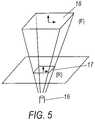
- FIG. 5illustrates a projection process required to generate an image from an object placed in between an x-ray source and an image intensifier.
- FIG. 6shows a variation of how to estimate or determine the distances from the x-ray source to the bed and to the image intensifier.
- FIG. 7shows a variation for determining or estimating the axis of rotation by searching for its offsets from a source.
- FIG. 8shows another variation for determining or estimating the axis of rotation by searching for its offsets from a source.
- FIG. 9shows a perspective projection mechanism, which shows how a fluoro image may be acquired.
- FIG. 10Ashows a technique for performing fluoro registration using a single image.
- FIG. 10Bshows a fluoro image having a bed sensor visible therein, for performing fluoro registration using a single image.
- FIG. 11illustrates a variation of a localization system integrated with a robotically controlled instrument or surgical system.
- FIG. 12illustrates a variation of a localization system integrated with a robotically controlled instrument or surgical system.
- FIG. 13illustrates a variation of a localization system integrated with a robotically controlled instrument or surgical system.
- FIG. 14illustrates a variation of a localization system integrated with a robotically controlled instrument or surgical system.
- FIG. 15illustrates a variation of a localization system integrated with a robotically controlled instrument or surgical system.
- FIG. 16Aillustrates an example of an elongate instrument such as a conventional manually operated catheter.
- FIG. 16Billustrates another example of an elongate instrument such as a robotically-driven steerable catheter.
- FIG. 17illustrates a raw fluoroscopic image
- FIG. 18illustrates an active contour tracking an elongate instrument.
- FIG. 19illustrates various displays showing templates, template matching, and coefficients along an active contour.
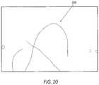
- FIG. 20illustrates a processed image showing filtering and removal of tracked elongate non-instrument members.
- FIG. 21illustrates a variation of a pixel sampling strategy around each node in an active contour.
- FIG. 22illustrates a flow chart describing a variation of a process for tracking an elongate instrument.
- FIG. 23illustrates use of a filter such as the second derivative of Gaussian.
- FIGS. 24 and 25illustrate a system utilizing multiple images.
- Various localization systems and methods for tracking, performing localization of, and/or controlling an elongate instrumente.g., a robotically controlled elongate instrument, in real time, in a clinical or other environment, are described herein.
- Various elongate instrumentsare contemplated for use in the various systems described herein, e.g., a catheter or vascular catheter.
- the various methods and systemsmay include integrating or registering a localization system or a localization sensor coupled to an elongate instrument, with an image.
- a Traxtal electromagnetic tracking or localization systemis one example of a system that allows for the tracking of a location, position and/or orientation of a localization sensor placed in a pulsating electromagnetic or magnetic field.
- Various localization sensorsmay be utilized, e.g., electromagnetic sensors, fiber optic sensors, and other sensors for detecting or controlling the movement of medical equipment.
- the localization sensorWhen the localization sensor is integrated into an image, it enhances the capabilities of an elongate instrument control or tracking system by allowing a user or doctor to easily navigate the elongate instrument through the complex anatomy without exposing the patient to excessive radiation over a prolonged period of time.
- the localization data or tracking information of a localization sensormay be registered to the desired image or model in order for navigation of an elongate instrument through the image or model to accurately represent movement of the elongate instrument.
- the registration processoften requires information about the imaging system providing the image, such as its physical dimensions and/or the details about the imaging techniques used to acquire a particular 3D model or other image. Due to the variability in equipment used in a clinical environment, in certain situations there may be no guarantee that such information will be available or easily obtainable to an outside party. As such, various robust techniques to estimate system parameters and various registration techniques may help facilitate the clinical use of localization technology.
- a method for tracking, localizing or controlling a robotically controlled elongate instrument in real timemay include displaying an image of a patient's anatomy.
- a localization sensormay be coupled to the robotically controlled elongate instrument.
- the localization sensormay provide localization data of the sensor and/or elongate instrument.
- the localization data from the localization sensormay be registered to the image.
- Registeringmay include transforming localization data generated by the localization sensor to the coordinate system of the image such that localization data of the elongate instrument, to which the localization sensor is coupled, is overlaid on the image.
- the coordinate system of the localization sensormay be transformed or translated to the coordinate system of the image through one or more transformations, and optionally through other coordinate systems, to register the localization data to the image.
- a continuously or substantially continuously updated location of at least a portion of the elongate instrumentis provided in the image of the anatomy of a patient, which allows for or facilitates robotic navigation or control of the elongate instrument through the anatomy e.g., through the vasculature of a patient.
- the location, position and/or orientation of the localization sensormay be continuously tracked to allow for accurate manipulation of the elongate instrument in or through the anatomy of a patient.
- Various types of imagesmay be utilized in the methods and systems described herein.
- an imagemay be generated by CT or 2D or 3D fluoroscopy.
- An imagemay include a 3D or 2D anatomical model or a 2D or 3D fluoroscopic image or other types of images useful for visualizing an anatomy of a patient to perform various medical procedures.
- an image intensifierWhen using a fluoroscopy image, an image intensifier may be utilized. Localization data from the localization sensor may be registered to a fluoroscopy coordinate system of a fluoroscopy image coupled to the image intensifier. In order to register the localization data from the localization sensor to the fluoroscopy image, various parameters may be ascertained or known. For example, such parameters may include: a distance from an X-ray source to the image intensifier, a distance from the source to a bed, a size of the image intensifier, and/or the axis of rotation of a c-arm of the fluoroscopy system.
- the localization sensormay include an electromagnetic localization sensor.
- the electromagnetic localization sensormay be placed in a pulsating magnetic field generated by an electromagnetic field generator or transmitter to allow for detection or tracking of the localization sensor.
- a system for tracking, localizing or controlling a robotically controlled elongate instrumentmay include an image of an anatomy of a patient, an electromagnetic localization sensor coupled to an elongate instrument, and an electromagnetic field generator.
- the imagemay be displayed, generated or otherwise received by the system.
- the electromagnetic field generatormay produce an electromagnetic field in which the electromagnetic localization sensor is detected.
- the localization sensormay provide localization data for at least a portion of the elongate instrument.
- the localization datais registered to the image by performing one or more transformations to provide a continuously or substantially continuously updated location of at least a portion of the elongate instrument in the image. This facilitates or allows for robotic navigation or control of the elongate instrument through the anatomy, e.g., through the vasculature of a patient.
- an imagemay be generated by CT or 2D or 3D fluoroscopy.
- An imagemay include a 3D or 2D anatomical model or a 2D or 3D fluoroscopic image or other types of images useful for visualizing an anatomy of a patient to perform various medical procedures.
- a location, position and/or orientation of the localization sensoris measureable in a coordinate system of the electromagnetic field generator.
- the location, position and/or orientation measurement of the localization sensormay be registered to the image via one or more transformations.
- an image intensifierWhen using a fluoroscopy image, an image intensifier may be utilized. Localization data from the localization sensor may be registered to a fluoroscopy coordinate system of a fluoroscopy image coupled to the image intensifier. In order to register the localization data from the localization sensor to the fluoroscopy image, various parameters may be ascertained or known. For example, such parameters may include: a distance from an X-ray source to the image intensifier, a distance from the source to a bed, a size of the image intensifier, and/or the axis of rotation of a c-arm of the fluoroscopy system.
- a system for tracking, localizing or controlling a robotically controlled elongate instrumentmay include an image of an anatomy of a patient, an electromagnetic localization sensor coupled to an elongate instrument, an electromagnetic field generator; and one or more reference sensors, e.g., fixed reference sensors, positioned in a workspace of the electromagnetic field generator.
- the electromagnetic field generatormay be movable relative to the reference sensor thereby extending or expanding the workspace for elongate instrument tracking or in which the elongate instrument may be tracked.
- the reference sensorprovides a reference coordinate system that is independent of the placement of the electromagnetic field generator.
- the localization sensorprovides localization data for at least a portion of the elongate instrument.
- the localization datais registered to the image via the reference coordinate system, to provide a continuously or substantially continuously updated location of at least a portion of the elongate instrument in the image. This facilitates or allows robotic navigation of the elongate instrument through the anatomy.
- a location, position and/or orientation of the localization sensormay be measured in the reference sensor coordinate system.
- the location, position and/or orientation measurement of the localization sensoris registered to the image via one or more transformations.
- a transformationmay be fixed in space and may not require online computation.
- the electromagnetic field generatormay be moved or rotated without distorting a measurement of the localization sensor as the localization sensor is measured in the reference sensor coordinate system.
- the reference sensormay include an anatomy patch.
- the anatomy patchmay be positioned on a patient such that the reference sensor appears in the image.
- a location, position and/or orientation of the reference sensorcan be measured in the coordinate system of the image.
- an imagemay be generated by CT or 2D or 3D fluoroscopy.
- An imagemay include a 3D or 2D anatomical model or a 2D or 3D fluoroscopic image or other types of images useful for visualizing an anatomy of a patient to perform various medical procedures.
- a location, position and/or orientation of the localization sensoris measureable in a coordinate system of the electromagnetic field generator.
- the location, position and/or orientation measurement of the localization sensormay be registered to the image via one or more transformations.
- an image intensifierWhen using a fluoroscopy image, an image intensifier may be utilized. Localization data from the localization sensor may be registered to a fluoroscopy coordinate system of a fluoroscopy image coupled to the image intensifier. In order to register the localization data from the localization sensor to the fluoroscopy image, various parameters may be ascertained or known. For example, such parameters may include: a distance from an X-ray source to the image intensifier, a distance from the source to a bed, a size of the image intensifier, and/or the axis of rotation of a c-arm of the fluoroscopy system.
- a method of tracking, localizing or controlling a robotically controlled elongate instrument in real timemay include: displaying a single image of an anatomy of a patient; tracking a localization sensor coupled to the robotically controlled elongate instrument; and registering localization data from the localization sensor to the image via one or more fixed reference sensors to provide a continuously updated location of at least a portion of the elongate instrument in the image of the anatomy of a patient to facilitate robotic navigation of the elongate instrument through the anatomy. Only a single image may be required to register the localization data. A location, position and/or orientation measurement of the localization sensor may be registered to the image via one or more transformations.
- a fluoroscope for creating the displayed imagemay remain fixed and may not be required to rotate or move to complete the registration.
- the electromagnetic field generatormay be movable relative to the fixed reference sensor, thereby expanding the workspace for elongate instrument tracking or in which the elongate instrument may be tracked.
- a localization system as described hereinmay include two subsystems, an imaging subsystem and a tracking subsystem.
- the imaging subsystemis used to acquire and visualize patient data.
- a CT scanmay provide a 3D model of the patient's anatomy and a fluoroscopy imaging system may provide an X-ray view of the patient's anatomy during an operation.
- the tracking subsystemcontinuously tracks the location, position and/or orientation of the sensor, allowing the doctor to manipulate the elongate instrument or tool to which the sensor is coupled, with ease.
- the two subsystemsare put together via a registration process, which transforms the localization or tracking data so that it appears correctly when overlayed on top of the acquired image.
- FIG. 1shows one variation of a localization system.
- a typical operation room set upincluding a bed 1 , a fluoroscopy system 2 and an electromagnetic field generator 4 positioned next to the bed 1 for tracking or detecting the location of a localization sensor 6 is shown.
- the localization sensor coordinate system (S)is fixed to the sensor 6 to provide the location, position and/or orientation of the sensor 6 .
- the sensor 6may be coupled to an elongate instrument.
- the elongate instrumentis not shown in FIG. 1 , but examples of elongate instruments having a sensor coupled thereto, which may be used in the system of FIG. 1 or the systems illustrated in any of the other figures described herein are shown in FIGS. 16A-16B .
- the electromagnetic field generator coordinate system (T)is attached to the electromagnetic field generator 4 .
- the location of the localization sensor 6e.g., its position and/or orientation, may be measured in the coordinate system of the field generator.
- the reference coordinate system (R)is an alternative coordinate system attached to the reference sensor 7 . It is possible, and sometimes it may be more desirable, to locate and measure the localization sensor 6 in the reference sensor coordinate system (R).
- the fluoroscopy coordinate system (F)is attached to an image intensifier 8 , e.g., in the middle of the image intensifier.
- the model coordinate system (M)is the coordinate system used for describing the 3D model 9 or image (shown in display 10 ).
- localization datacan be registered to a 3D anatomical model or a fluoroscopy image.
- the techniques used to perform the registrationvary depending on the target. Where localization data is registered to a fluoroscopy image, the 2D nature of the fluoroscopy images may require that multiple images be taken at different angles before the registration process is complete.
- a marker that shows up in both or multiple imagesmay be provided or required.
- a convenient choiceis to embed a fluoro marker in the patient table so that the marker is visible in all fluoro images, effectively using it as the reference sensor. Once the marker is located in multiple images, its 3D position is easily identified via triangulation.
- a patient reference patchmay simplify the registration process. Since the 3D model is acquired during a pre-op CT scan, a patient reference patch worn during the scan provides the reference point for future registration. The patch is in essence a location sensor that also shows up in the CT scan. Because the patch provides its current position and orientation, there is enough information to align the 3D anatomical model to the patient during live cases once the patch is identified in the 3D model.
- the patient reference patchmay not be needed if the catheter is registered to a particular anatomical feature.
- the ideais to embed markers in the catheter and drive the catheter to the particular anatomical structure under the guidance of fluoro.
- a predefined section of the 3D model representing the anatomical structureis then registered to the catheter once the physician clicks through the markers to recognize their 3D location.
- the 3D modelis marked instead with a few easy-to-reach target locations.
- the physiciandrives the catheter to those locations in succession under fluoro, and registers the position and orientation of the catheter each time it reaches a target. After collecting a few data points, the 3D model can be registered to the catheter for use in live cases.
- a reference sensormay be utilized and may greatly simplify the registration process. While a localization sensor may be measured or tracked in the Traxtal or electromagnetic field generator coordinate frame, the Traxtal system may be sensitive to the presence of metal in or nearby its electromagnetic field generator. As such, close proximity of an image intensifier of a fluoroscopy system may have detrimental effects on the workspace of the localization or tracking system. This problem may be alleviated by the introduction of a reference sensor or an extra sensor placed in the workspace of the electromagnetic field generator.
- FIG. 2Ashows a workspace 11 of the electromagnetic field generator 4 without a reference sensor.
- FIG. 2Bshows an extended workspace 12 of the electromagnetic field generator 4 with a reference sensor 7 .
- FIG. 2Bshows the electromagnetic field generator 4 positioned in different locations.
- the electromagnetic field generator 4can be moved to different locations, thereby expanding the workspace for elongate instrument tracking or localization, due to the presence of the reference sensor 7 .
- the reference sensor 7sets up a reference coordinate frame or system (R), which provides an alternative coordinate system independent of the placement of the electromagnetic field generator 4 .
- the location, position and/or orientation of a localization sensormay be measured in the reference coordinate frame or system (R) instead of the electromagnetic field generator coordinate frame or system (T), via a transformation.
- the electromagnetic field generator 4may be moved around without distorting the measurement of the localization sensor in the reference coordinate frame, effectively extending the workspace 12 of the electromagnetic field generator 4 and the localization or tracking system.
- the reference sensormay be used as an anatomy patch 14 .
- the reference sensor anatomy patch 14may be worn by a patient during a pre-op scan so that the anatomy patch 14 appears in the resulting 3D model.
- the location, position and/or orientation of the anatomy patch 14may be described or measured in the model coordinate system or frame (M).
- the description of the anatomy patch 14defines the transformation between the reference coordinate frame and the model coordinate frame ( M/R T).
- FIGS. 3A and 3Bshow a reference sensor anatomy patch 14 applied to a patient for registration.
- FIG. 3Ashows a patient wearing an anatomy patch 14 as the patient is undergoing a pre-op scan.
- FIG. 3Bshows a 3D model or image showing both the patient and the anatomy patch 14 in the image.
- localization datacan be registered to a 3D anatomical model.
- the 3D registration processaligns the localization sensor measurement or localization data to the 3D model.
- the required transformations to complete the registrationmay differ slightly depending on whether a reference sensor is used in the localization sensor measurement or not.
- FIG. 4Adescribes a transformation for registering localization data or measurements from an electromagnetic localization sensor to a 3D model, where a location of the localization sensor 6 is measured in the Traxtal electromagnetic field generator 4 coordinate system (T).
- a transformation M/T T required to describe the localization sensor measurement from the Traxtal electromagnetic field generator coordinate system (T) in the 3D model 9 coordinate system (M)is shown in in FIG. 4A .
- FIG. 4Bdescribes the transformation for registering localization data or measurements from an electromagnetic localization sensor to a 3D model, where a location of the localization sensor 6 is measured in the reference sensor 7 coordinate system (R).
- a transformation M/R Trequired to describe the localization sensor measurement from the reference sensor coordinate system (T) in the 3D model 9 coordinate system (M) is shown in in FIG. 4B .
- the transformation M/R Tis simpler than the transformation M/T T.
- the transformation M/R Tmay not require any online computation.
- the transformation M/R Tmay be fixed in space and does not need to be computed again.
- transformation M/R Tmay be computed offline once the model is acquired.
- M p S and R p Sare position vectors to the localization sensor described in the model coordinate system and in the reference coordinate system.
- localization datacan be registered to a fluoroscopy image.
- the fluoro registration processmay align the localization sensor measurement or localization data (e.g., from a Traxtal system or electromagnetic sensor) to a 2D fluoroscopy image.
- FIG. 5shows a projection process required to generate an image from a 3D object or other object placed in between a source or x-ray source 16 and an image intensifier 18 . The ray coming out of the x-ray source 16 goes through the object and reaches the image intensifier 18 to produce a fluoroscopy image.
- a fluoro registration processmay be closely related to the process of projecting the localization data onto the x-y plane of the fluoroscopy coordinate system.
- FIG. 5also shows a reference sensor 17 having a reference coordinate frame (R). A projection matrix may be used to transform the reference coordinate system (R) to the fluoroscopy coordinate system (F).
- Information about the imaging systemmay be required to perform the fluoro registration process.
- the information or parameters of interestmay include: the size of the image intensifier; the distance from the x-ray source to the image intensifier; the distance from the x-ray source to the bed; and the axis of rotation if the fluoro imaging system or C-arm is to be rotated.
- a preliminary calibration stepmay be necessary to obtain such information unless it is readily provided by the manufacturer of the imaging system.
- the physical dimension of the image intensifierhelps determine the scale factor, which provides a mapping from pixels to millimeters. It is computed from comparing the size of the image intensifier to that of the window showing the fluoro image so that 1 pixel difference in the fluoro image corresponds to the correct length in millimeters in the real world.
- FIG. 6describes a variation of how to estimate or determine (fluoro calibration) the distances from the x-ray source 16 to the bed 19 and to the image intensifier 18 using an object of known dimensions.
- FIG. 6shows a side view of the system where the bed 19 is at x away from the source 16 and the image intensifier 18 is at y away from the source 16 .
- To calculate the unknowns x and yimagine there are two disks of known radii, r 1 and r 2 , stacked up together with known distance of separation, d. The radii of the disks appearing on the fluoro image are measured as s 1 and s 2 , respectively.
- the relationship among the variablesare described by the following equations:
- the fluoro imagemay be taken at an oblique angle, which may require the C-arm of the fluoroscopy image to be rotated.
- the x-ray source and the image intensifierare not always perfectly lined up with the axis of rotation, which may remain to be found.
- FIGS. 7 and 8describe various ways of determining or estimating the axis of rotation by searching for its offsets from a source.
- d x and d zrepresent the offsets along the x and z axes, respectively, and d denotes the distance from the source to an object, which can be placed on the bed to take advantage of the known distance to the bed.
- the calibration processstarts with locating the object in the AP view and then in the LA view. Basically, this process identifies a direction vector from the source to the object of interest in two different set ups. Angles ⁇ and ⁇ are defined from the AP view as:
- x 1are x 2 are the x component of the direction vectors toward the object in the AP and LA views.
- Rodrigues' formulawidely used in kinematics and robotics, may provide a convenient and robust method to locate the axis of rotation.
- s o n1 2 ⁇ ( p 1 + p 2 + s ⁇ ( p 2 - p 1 ) tan ⁇ ( a 2 ) - ( s ⁇ ( p 1 + p 2 ) ) ⁇ s )
- S onis the point of interest on the axis of rotation normal to the origin of the global coordinate system
- p 1 and p 2are the locations of the object in the fluoro coordinate system in LA and AP views
- sis the unit vector along the axis of rotation
- ⁇is the degree of rotation. In this case, s is (0, 1, 0) T and ⁇ is ⁇ /2.
- mapping to the fluoro coordinate systemmay be established.
- a perspective projection mechanism(from a source to an image intensifier) is described in FIG. 9 , showing how the fluoro images may be acquired.
- the localization datashould be represented in the fluoro coordinate system.
- the transformation F/R Tis generated when the reference sensor is located in multiple fluoro images taken at different angles.
- the AP viewi.e., the top view
- the LA viewi.e., the side view
- fluoro registrationmay be performed using a single image.
- a transformationmay be generated with a single fluoro image. This would involve use of another sensor, e.g., a sensor 20 being fixed to the bed, which would provide the bed coordinate system (B).
- a bed sensor and/or reference sensormay be fixed or have a known location.
- This single image fluoro registration processcomputes a transformation between the fluoro coordinate system (F) and the bed coordinate system (B), i.e., F/B T and then uses B/R T to get the desired transformation F/R T.
- B/R Tis computed by taking the difference between the two sensor readings, i.e. the relative measurement between the bed 20 and the reference 21 sensors.
- the ideais to use a sensor instead of a fluoro marker to locate the bed in 3D space.
- a bed sensorprovides a couple of key advantages: frame transformation between the bed and the reference sensor, and robustness to table tilting. As noted before, it is possible to figure out the exact location of the bed sensor in fluoro coordinate system once distances among the source, the bed and the image intensifier are discovered. What is different this time is that the bed sensor provides a relative transformation to the reference sensor because both are measured in the same Traxtal or other sensor coordinate system. This facilitates the computation of reference sensor position and orientation in fluoro coordinate system, which is what is desired. In addition, the bed sensor provides orientation information as well as position data.
- Bed sensor measurement in the fluoro coordinate systemis robust to table tilting because the measurement already reflects the change in table orientation. This allows the physician to reposition or reorient the patient as need arises in the tightly spaced operating room.
- the process for single image registrationis similar to normal fluoro registration that requires fluoro images taken at multiple angles, except that there is no need to rotate the fluoro C-arm and thus saves preparation time and operating room space significantly.
- the operatorlocates the bed sensor 20 in the fluoro image 24 ( FIG. 10B ) to generate an imaginative ray stemming from the source 22 that goes through the bed sensor 20 as shown in FIG. 10A .
- the exact location of the bed sensor 20is then determined using the knowledge of the source 22 to the image intensifier 23 distance and the height of the bed 25 , and then the translation of the origin F/B O is calculated from taking the difference in position between (F) and (B).
- an electromagnetic localization sensor or Traxtal systemmay be integrated with a Hansen robotically controlled elongate instrument or catheter.
- various localization systemsmay be integrated with a robotically controlled elongate instrument or surgical system, e.g., electromagnetic sensor based systems, Traxtal systems, and fiber optic based localization systems.
- Various localization sensorsmay be used in any of the integrated systems described below, e.g., electromagnetic sensors, fiber optic sensors, etc.
- a medical system for controlling an elongate instrumentmay include a robotically controlled instrument assembly having a shapeable elongate instrument.
- a localization systemmay be coupled to the robotically controlled instrument assembly and configured to track the shapeable elongate instrument, wherein at least a portion of the localization system may be sterilely isolated from the robotically controlled instrument assembly.
- FIG. 11shows one example of a medical system 50 for controlling an elongate instrument.
- the system 50may include an integrated localization system.
- the localization systemmay include a localization sensor 52 coupled to a shapeable elongate instrument within a sterile field.
- the localization sensor 52may be coupled to a sensor detection unit 53 positioned outside of the sterile field via a connector 51 .
- the connector 51may be positioned within the sterile field.
- the connector 51may be positioned outside of the sterile field.
- coil lead wiresmay be directly soldered to a cable inside of the robotically controlled instrument assembly or splayer 54 , and then routed to the standard connector 51 connected to the sensor box or sensor detection unit 53 .
- a sterile guardmay be implemented on the connector 51 to produce the following workflow: 1. The connector 51 may be unplugged by a sterile assistant with isolation from the contaminated plug; 2. A flip cover or sterile guard my protect the contaminated plug; and 3. The assembly of wires and/or connector, now sterile, can be placed in the sterile field, e.g., on a tray, when the catheter or elongate instrument is removed.
- FIG. 12shows another example of a medical system 60 for controlling an elongate instrument.
- the system 60may include an integrated localization system.
- the localization systemmay include a localization sensor 62 coupled to the shapeable elongate instrument within a sterile field.
- the localization sensor 62may be coupled to a sensor detection unit 63 positioned outside of the sterile field via an extension cord or wire 64 and a connector 61 .
- At least a portion of the wire 64may be positioned in the sterile field and the connector 61 may be positioned outside of the sterile field.
- a second connector 65 for coupling the localization sensor to the sensor detection unitmay be included.
- the second connector 65may be positioned within the sterile field.
- the second connector 65may be robust or resistant to bodily fluids.
- a sterile cord or wire 64may connect through a drape to a jack on the robotically controlled instrument assembly or splayer 66 , which is internally wired to lead wires of the sensor coils.
- the disconnection procedure for this systemmay be as follows: 1. Remove the plug or connector 65 from the splayer jack; 2. Lay the plug and cord 64 on the table (still in the sterile field); and 3. Remove the full catheter or elongate instrument. Since the sterile end of the cord 64 stays in the sterile field, there is no contamination on reconnection. Also, there is no unwieldy cable that needs to be managed.
- the sensor box or sensor detection unitmay be integrated into the computer (e.g., a Traxtal sensor box may be integrated into a Traxtal computer) to reduce the number of items at a bedside.
- FIG. 13shows another example of a medical system 70 for controlling an elongate instrument.
- the system 70may include an integrated localization system.
- the localization systemmay include a localization sensor 72 coupled to the shapeable elongate instrument within a sterile field.
- the localization sensor 72may be coupled to a sensor detection unit 73 positioned outside of the sterile field via a cord or wire 74 and a connector 71 .
- the entire or substantially all of the wire 74may be positioned outside of the sterile field.
- a connector 71may be implemented under the robotically controlled instrument assembly or splayer 75 , routed through an instrument driver 76 or RCM and then out to the sensor box 73 or sensor detection unit or a bedside box, e.g., a Traxtal bedside box including both a Traxtal sensor box and a Traxtal computer.
- a connector 71may be implemented under the robotically controlled instrument assembly or splayer 75 , routed through an instrument driver 76 or RCM and then out to the sensor box 73 or sensor detection unit or a bedside box, e.g., a Traxtal bedside box including both a Traxtal sensor box and a Traxtal computer.
- FIG. 14shows another example of a medical system 80 for controlling an elongate instrument.
- the system 80may include an integrated localization system.
- the localization systemmay include a localization sensor 82 coupled to the shapeable elongate instrument within a sterile field.
- the localization sensor 82may be coupled to a sensor detection unit 83 .
- the sensor detection unit 83may be integrated into an instrument driver 86 coupled to a robotically controlled instrument assembly 85 or splayer.
- the sensor detection unit 83may communicate via a digital signal with a sensor controller 87 positioned outside of the sterile field. As shown in FIG.
- the sensor detection unit 83 or sensor amplifier boardsmay be placed into the instrument driver 86 or RCM, allowing digital signals to be routed to a sensor controller 87 or Traxtal computer positioned outside of the sterile field, e.g., located in a Hansen rack 88 , which may include visualization/robot control computers, router to manage communication between computers, and/or power electronics).
- a sensor controller 87 or Traxtal computerpositioned outside of the sterile field, e.g., located in a Hansen rack 88 , which may include visualization/robot control computers, router to manage communication between computers, and/or power electronics).
- an electromagnetic field generator of the localization systemis positioned in a rack
- a small electromagnetic field generator boxwhich converts an analog signal into a digital signal to drive the sensor coils
- an addition to a field generatormay be made to avoid analog transfer of information.
- the electromagnetic field generator boxmay be placed in the RCM or instrument driver.
- FIG. 14shows another example of a medical system 90 for controlling an elongate instrument.
- the system 90may include an integrated localization system.
- the localization systemmay include a localization sensor 92 coupled to the shapeable elongate instrument within a sterile field.
- the localization sensor 92may be coupled to a sensor detection unit 93 .
- the sensor detection unit 93 or amplifiermay be integrated in the robotically controlled instrument assembly 95 and the sensor detection unit 93 may wirelessly communicate, e.g., via RFID, with a sensor controller 97 positioned outside of the sterile field.
- an amplifier or sensor detection unit 93may be placed into the robotically controlled instrument assembly or splayer 95 and transmit signals wirelessly. This would provide a no wire splayer interface.
- the robotically controlled instrument assemblymay be disposable.
- Various localization sensorsmay be used in any of the systems described herein, including electromagnetic localization sensors or fiber optic sensors.
- the various methods and system described hereinmay provide real time visualization of the movement or location of an elongate instrument or other medical instrument while avoiding or minimizing exposing a patient to excessive radiation.
- any of the medical systems, localization systems or tracking systems described hereinmay be coupled by wires and/or may be coupled wirelessly.
- FIGS. 16A and 16BExemplary elongate instruments for use in any of the localization or tracking systems described herein are illustrated in FIGS. 16A and 16B .
- a conventional manually-steerable catheter ( 101 )is depicted.
- Pullwires ( 102 )may be selectively tensioned through manipulation of a handle ( 103 ) on the proximal portion of the catheter structure to make a more flexible distal portion ( 105 ) of the catheter bend or steer controllably.
- the handle ( 103 )may be coupled, rotatably or slidably, for example, to a proximal catheter structure ( 134 ) which may be configured to be held in the hand, and may be coupled to the elongate portion ( 135 ) of the catheter ( 101 ).
- a more proximal, and conventionally less steerable, portion ( 104 ) of the cathetermay be configured to be compliant to loads from surrounding tissues (for example, to facilitate passing the catheter, including portions of the proximal portion, through tortuous pathways such as those formed by the blood vessels), yet less steerable as compared with the distal portion ( 105 ).
- a robotically-driven steerable catheter ( 106 )has some similarities with the manually-steerable catheter ( 101 ) of FIG. 16A in that it has pullwires or other control elements ( 101 ) associated distally with a more flexible section ( 108 ) configured to steer or bend when the control elements ( 110 ) are tensioned in various configurations, as compared with a less steerable proximal portion ( 107 ) configured to be stiffer and more resistant to bending or steering.
- the control elementscan be flexible tendons, or other mechanical structures that allow for steering or deflection of the catheter ( 106 ).
- the depicted embodiment of the robotically-driven steerable catheter ( 106 )comprises proximal axles or spindles ( 109 ) configured to primarily interface not with fingers or the hand, but with an electromechanical instrument driver configured to coordinate and drive, with the help of a computer, each of the spindles ( 109 ) to produce precise steering or bending movement of the catheter ( 106 ).
- the spindles ( 109 )may be rotatably coupled to a proximal catheter structure ( 132 ) which may be configured to mount to an electromechanical instrument driver apparatus, such as that described in the U.S. patent application Ser. No. 11/176,598, and may be coupled to the elongate portion ( 133 ) of the catheter ( 106 ).
- Each of the variations of elongate instrument depicted in FIGS. 16A and 16Bmay include a localization sensor 112 coupled thereto as described herein.
- the localization sensormay be positioned at the distal end or distal portion of the elongate instrument or along a length of the elongate instrument.
- Various localization sensorsmay be utilized such as electromagnetic sensors, fiber optic sensors, and other sensors known in the art.
- Each of the variations depicted in FIGS. 16A and 16Bmay have a working lumen (not shown) located, for example, down the central axis of the catheter body, or may be without such a working lumen.
- a working lumenmay extend directly out the distal end of the catheter, or may be capped or blocked by the distal tip of the catheter. It is highly useful in many procedures to have precise information regarding the position of the distal tip or other portion of such catheters or other elongate instruments, such as those available from suppliers such as the Ethicon Endosurgery division of Johnson & Johnson, or Intuitive Surgical Corporation.
- the examples and illustrations that followare made in reference to a robotically-steerable catheter such as that depicted in FIG.
- a method of controlling a robotically controlled elongate instrument in real timemay include one or more of the following steps: displaying an image of an anatomy of a patient; tracking or detecting a localization sensor coupled to the robotically controlled elongate instrument; and registering localization data from the localization sensor to the image to provide a continuously updated location of at least a portion of the elongate instrument in the image of the anatomy of a patient to facilitate robotic navigation of the elongate instrument through the anatomy.
- a system for tracking or localizing a robotically controlled elongate instrumentmay include: an image of an anatomy of a patient; an electromagnetic localization sensor coupled to an elongate instrument; and/or an electromagnetic field generator.
- the generatormay be configured to produce an electromagnetic field in which the electromagnetic localization sensor is detected.
- the localization sensormay provide localization data for at least a portion of the elongate instrument, where the localization data may be registered to the image to provide a continuously updated location of at least a portion of the elongate instrument in the image. This may facilitate robotic navigation of the elongate instrument through the anatomy.
- a system for tracking or localizing a robotically controlled elongate instrumentmay include: an image of an anatomy of a patient; an electromagnetic localization sensor coupled to an elongate instrument; an electromagnetic field generator; and/or at least one reference sensor, e.g., fixed reference sensor, positioned in a workspace of the electromagnetic field generator.
- the electromagnetic field generatormay be movable relative to the reference sensor thereby expanding the workspace for elongate instrument tracking.
- a method of tracking or localizing a robotically controlled elongate instrument in real timemay include one or more of the following steps: displaying a single image of an anatomy of a patient; tracking or detecting a localization sensor coupled to the robotically controlled elongate instrument; and/or registering localization data from the localization sensor to the image via a reference sensor to provide a continuously updated location of at least a portion of the elongate instrument in the image of the anatomy of a patient to facilitate robotic navigation of the elongate instrument through the anatomy.
- a medical system for controlling an elongate instrumentmay include a robotically controlled instrument assembly comprising a shapeable elongate instrument.
- the systemmay include a localization system coupled to the robotically controlled instrument assembly and configured to track the shapeable elongate instrument, where at least a portion of the localization system is sterilely isolated from the robotically controlled instrument assembly.
- a system or robotic system for controlling an elongate instrument with respect to a target spacemay include an elongate instrument having a localization sensor coupled thereto.
- the systemmay include a robotic drive system including at least one actuator, where the robotic drive system is configured to interchangeably couple with the elongate instrument to position the instrument with respect to the target space.
- the systemmay also include a controller configured to produce a registration between a localization sensor frame and an image frame or a patient frame. The controller can produce a plurality of signals to direct the robotic drive system or elongate instrument in the image frame using the registration and the image may include an image of the target space or patient.
- the localization sensormay be any of various localization sensors, e.g., an electromagnetic localization sensor.
- An electromagnetic localization sensormay be placed in a pulsating magnetic field generated by an electromagnetic field generator to allow for sensor detection or tracking.
- a position and/or orientation of the localization sensormay be continuously tracked to allow for accurate manipulation of the elongate instrument.
- imagesmay be utilized, e.g., images generated by CT or 2D or 3D fluoroscopy.
- the imagemay be a 3D or 2D anatomical model or a 2D or 3D fluoroscopic image.
- Registeringmay include transforming localization data generated by the localization sensor to the coordinate frame of the image such that localization data of the elongate instrument is overlaid on the image.
- An image intensifiermay be provided, where localization data from the localization sensor may be registered to a fluoroscopy coordinate system of a fluoroscopy image coupled to an image intensifier. Registration to a fluoroscopy image may be produced by knowing: a distance from an X-ray source to the image intensifier, a distance from the source to a bed, a size of the image intensifier, and/or the axis of rotation of a c-arm of a fluoroscopy system.
- the robotically controlled elongate instrumentmay be a vascular catheter or other catheter.
- the registrationmay be used to facilitate intuitive or instinctive driving of the elongate instrument.
- a single image or multiple imagesmay be utilized.
- a master input devicemay be coupled to the controller, where the master input device uses the registration to permit intuitive or instinctive driving of the elongate instrument using the robotic drive system.
- a robotic system for controlling an elongate instrument with respect to a target spacemay include an elongate instrument having a localization sensor coupled thereto.
- the systemmay include a robotic drive system having at least one actuator.
- the robotic drive systemmay be configured to interchangeably couple with the elongate instrument to position the instrument with respect to the target space.
- the systemmay include a controller configured to register localization data from the localization sensor to an image of an anatomy or to a patient or target space frame to provide a continuously updated location of at least a portion of the elongate instrument in the image.
- the controllercan produce a plurality of signals to direct robotic navigation of the elongate instrument through the anatomy based on the location of at least a portion of the elongate instrument in the image.
- the controllermay be configured to convert a user input into a plurality of signals based on the registration of a sensor reference frame to the image frame or target space or patient reference frame.
- a master input devicemay be coupled to the controller, where the master input device uses the registration to permit intuitive or instinctive driving of the elongate instrument using the robotic drive system.
- a system or method for tracking or vision tracking a medical instrument or elongate instrumentmay perform or require one or more of the following steps.
- One or more of a sequence of pointsmay be identified to initialize an active contour or outline of at least a portion of the elongate instrument.
- the active contourmay correspond to at least a portion of the elongate instrument.
- the active contourmay be updated or modified (e.g., lengthened or shortened) as the elongate instrument moves by performing a pixel intensity or density search, focused pixel intensity or density search, color intensity search or other similar search.
- the active contourmay be updated or modified by searching for a change in pixel density or intensity or a change in brightness in the image, e.g., in a fluoroscopy image or other image.
- An image-based searche.g., a template matching search
- the image-based searchmay be performed to track the active contour or to track a feature, marker or point of interest of the elongate instrument in order to enhance or confirm the accuracy of the active contour.
- the image-based searchmay be performed to track a feature, marker or point of interest of the elongate instrument to ascertain the location of the specific feature, marker or point of interest on the active contour or to track the specific feature, marker or point of interest on the active contour.
- the image-based searchmay consist of an image correlation computation.
- the active contourmay restrict the area in which the image-based search or template matching search will occur and the active contour may provide a seed or initiation for the orientation of a template.
- the image-based or template matching searchmay be performed to track specific features, markers or points of interest on or coupled to the elongate instrument.
- Features, markers or points of interestmay include, e.g., an articulation section, control ring, elongate instrument tip or a sheath.
- templatesmay vary based on the type and size of the specific feature, marker or point of interest on the elongate instrument being tracked.
- the template matching searchmay be a low computation search that may not take into consideration every single pixel value or all possible locations of the template match.
- the active contour tracking and/or the image-based searchmay facilitate or allow for instinctive driving of the elongate instrument.
- the active contour tracking and/or the image-based searchmay allow the user to track or know the heading direction of the elongate instrument or an articulation section of the elongate instrument, or to track or know the direction of articulation of the elongate instrument, which facilitates or allows for instinctive driving of the elongate instrument, e.g., of a robotically controlled elongate instrument or catheter.
- Instinctive drivinginvolves the tip of an elongate instrument, e.g., a catheter, moving in the same direction as the command input motion irrespective of the headed direction or orientation of the catheter tip.
- the systemneeds to know the heading direction and rotational orientation of the tip of the instrument at all times or substantially all times, so that it can translate the user input commands accordingly to give the desired output. For example, if a catheter tip is straight inside the body, then a user command to bend left will cause the robotic system to pull the left pull wire or control wire, and the catheter tip will bend left.
- the catheter tiphas rotated 90° in the clockwise direction inside the body, then when the user commands a left bend, if the robotic system were to pull the left wire, the catheter tip would bend upward. If, however, the robotic system knows the orientation of the tip, then the system will know that it needs to pull on the down wire to get the tip to move left according to the users input.
- a low resolution spatial filter or other filtermay be used to filter out high frequency texture and/or noise in an image.
- a particle filtermay be used to maintain multiple tracking hypotheses in order to overcome any unnecessary obscuring or blocking of a feature, marker or point of interest of the elongate instrument being tracked in an image.
- a particle filtermay be used to guide template matching.
- images or imaging systemsmay be utilized to obtain, receive or otherwise display an image. The images may include a fluoroscopy image, 3D image or model or any other image or imaging technology suitable for use in medical procedures.
- the active contourmay track one or more edges of the elongate instrument in the image.
- the active contourmay specifically track two edges or lines with a darker area between the edges corresponding to the shaft of the elongate instrument. Spacing may be maintained between at least two points in a sequence of points making up the active contour and the spacing may prevent the active contour from mis-tracking, e.g., in areas where the elongate instrument curves rapidly.
- the active contourmay be updated by using an iterative approach.
- the active contourmay be updated by using one or more iterations or wherein each iteration refines the location of the active contour to the image. Any number of iterations may be used.
- the active contourmay grow and shrink as a projection of the elongate instrument on the image grows and shrinks, thereby tracking the elongate instrument. Points may be added or removed at a desired distance from an end point of the active contour in the direction that the active contour is traveling to grow or shrink the active contour, in order to track movement of the elongate instrument. Each point along an active contour may produce a fitness value that can guide whether or not that point is on or aligned with the elongate instrument in the image.
- an active contourmay be initialized by selecting two or more points along a shape or path of the elongate instrument in the image using a pointing device, a touch screen or other selection mechanism.
- an active contourmay be initialized by identifying points on a leader, control ring marker, a sheath marker or other portion of the elongate instrument or sheath. The points may initialize the contour and provide a starting location for tracking a leader, control ring marker, sheath marker or other potion of the elongate instrument or sheath.
- a correlation matching searchmay be performed along the active contour to track features or specific points of the elongate instrument and to enhance or confirm accuracy of the active contour.
- one or more secondary active contours for tracking elongate non-instrument objectsmay be provided.
- the elongate non-instrument objectsmay be artificially removed from the image if desired.
- a portion of one or more non-elongate non-instrument objectsmay be tracked within the image using one or more other computer vision technologies such as pattern matching, optical flow, feature matching, or shape matching.
- the non-elongate non-instrument objectsmay be artificially removed from the image if desired.
- more than one elongate instrument objectmay be attracted by using more than one active contour.
- Each active contourmay be tracked independently of the other active contours.
- a tracking viewmay be overlaid on a fluoroscopy image or other image, and a user's view of the image may be augmented or modified to best visualize and track the elongate instrument.
- a first active contour of at least a portion of the elongate instrument or a flexible elongate instrument bodymay be created, where the active contour tracks the elongate instrument.
- a template matching searchmay be performed along the active contour for tracking features of the flexible elongate instrument body.
- a second active contour for tracking elongate non-instrument objectssuch as wires, stents, or surgical sutures may also be created.
- the elongate non-instrument objectsmay be artificially removed from the image.
- the imagemay be a fluoroscopy image or other image as described herein.
- a method of tracking a robotically controlled elongate instrument in real time in an imagemay include identifying a sequence of points to initialize an active contour of at least a portion of the elongate instrument.
- the active contourmay be updated as the elongate instrument moves by performing a focused pixel intensity or density search.
- Movement of the elongate instrumentmay be predicted based on previous robotic or system commands, where the robotic or system commands are taken into consideration or are used as factors in predicting the location or movement of the elongate instrument in the image to help with accurately tracking the elongate instrument.
- a method of tracking a robotically controlled elongate instrument in real time in an imagemay include one or more of the following steps: controlling movement of the elongate instrument with a robotic or system command; creating an active contour of the elongate instrument; updating the active contour as the elongate instrument moves; performing a template matching search along the active contour to track features of the elongate instrument; and predicting elongate instrument movement based on the commanded elongate instrument motion to increase tracking accuracy.
- a command for elongate instrument motionmay be utilized to predict where the elongate instrument will be moving in the image.
- a command for elongate instrument motionmay be utilized to predict a location or shape of the active contour in the image.
- a command for elongate instrument motionmay be utilized to focus a pixel density search to update the active contour and/or to focus a template matching search to track features of the elongate instrument in the image.
- a command for elongate instrument motionmay be utilized to eliminate false positives during tracking.
- a known distance between a first point and a second point on an elongate instrumentmay be used to guide or focus a template matching search for the first point based on the position of the second point.
- a command for elongate instrument motionmay be utilized to give guidance on the scale of pixels per millimeter on an image and/or to give guidance on the amount or distance that an elongate instrument is moving out of plane.
- FIG. 17shows a sample fluoroscopy image that is the source image for other figures described herein.
- FIGS. 18 through 21show various components or steps of a variation of a system or method for tracking an elongate instrument.
- FIG. 18shows a visual representation of the tracked information overlaid on a representation of the fluoroscopy image (e.g., within the robotic system visual application.
- the viewshows a solid line 200 following the track of the elongate instrument, solid points 202 denoting the nodes of the active contour, and two dashed pentagons 204 showing the location of a sheath and leader control rings along with their orientation direction.
- Elongate instrument trackingmay provide vision tracking of the elongate instrument in a fluoroscopy or other view. It may provide localization in at least two dimensions, including orientation in the plane that can be used to guide instinctiveness and to augment other localization techniques.
- an elongate instrumentmay include a catheter, guidewire, probe or other medical instrument.
- elongate instrument trackingmay be performed using an active contour (“snake”) that tracks at least a portion of the elongate instrument, e.g., the shaft or articulation section, in an image, e.g., a fluoroscopy image.
- An active contouris a curvilinear model that attempts to minimize an energy function between the shape and the image.
- the active contourmay delineate an outline of the elongate instrument in an image. Identifying, selecting and/or maintaining a set of points (or nodes) on a curve by minimizing an energy function may create an active contour.
- Terms of the energy functionmay maintain the spacing between the points of an active contour, minimize curvature (since elongate medical devices may resist sharp bends and may typically remain straight), and/or maintain proximity to the curve or shape of the elongate instrument in the image.
- an energy function or algorithmmay be used to maintain the spacing between points or nodes.
- an energy functionmay be in the form of a cost function or algorithm, such that when two points or nodes move closer together, the cost or risk increases, and the distance between the points is lengthened, increased or maintained by the cost function or algorithm.
- the energy functionmay be an arbitrary function that provides a penalty if points or nodes move too close together and the function causes a first point or node to be pushed away or forced apart from a second point or node to improve the accuracy of the tracking of an elongate instrument.
- the spacing between points or nodes of an active contourmay also be maintained or controlled to prevent the active contour from mis-tracking in areas where the elongate instrument curves rapidly. The end result is a sequence of points that tracks the elongate instrument or flexible device and grows or shrinks as a projection of the elongate instrument grows and shrinks.
- An active contourmay be designed to track one or more edges, e.g., edges of an elongate instrument, in an image, using an energy term or function.
- the energy term or functionmay be minimized when the active contour is on an edge or when the active contour is on two edges of an elongate instrument.
- a darker areamay be visible on the image, inside or in between the two edges.
- an energy function term that maintains spacing between nodes or points of an active contourmay automatically space the nodes out in an optimal or desired manner or degree.
- the nodes or pointsmay be combined to maintain good contour coverage. If two nodes or points get sufficiently far from each other, a new node or point may be created or identified between the two nodes or points.
- elongate instrument trackingmay be carried out on an image that has been normalized with a medium-pass filter.
- Certain dark or light regions that take up a large portion of the imagecan be filtered out by subtracting the results of a low pass filter from the original image. For example, referring to FIG. 17 , the large dark area (the bladder) is filtered out in the processed image in FIG. 20 .
- filteringcan remove the high frequency noise that manifests itself as speckles and texture due to the imaging device.
- various filtersmay be used to detect the shape of an elongate instrument or a catheter in an image, e.g., a fluoroscopy image.
- the local ridge-like structure of the catheter in an X-ray imageis characterized by the direction of flow of the ridge and the thickness of the catheter ridge structure.
- the second derivative of the Gaussianmay be used to analyze such ridge-like structures via the construction of the Hessian matrix and the spectral analysis of this matrix.
- Using the accurate form of the second derivative of the Gaussianmay require computations that are proportional to the size of the catheter in the image.
- This computational challengecan be overcome using filters that approximate the second derivative of the Gaussian.
- the computational loadis independent of the size of the catheter in the image.
- the approximate second order Gaussian derivativescan be approximated using piecewise constant filters. See FIG. 23 .
- approximate second derivative of Gaussian filtermay be in the YY direction.
- Corresponding filtersmay be generated for the XX and XY case.
- the computational efficiency of the filteringcan be made independent of the Gaussian smoothing by the use of accumulator images.
- the smoothing parameter of Gaussian(in pixels) may be equal to the width of the catheter in the image.
- Tracking a robotically controlled elongate instrument using an active contourmay include identifying one or more or a sequence of points to initialize or create an active contour of at least a portion of the elongate instrument.
- the selection or identification of one or more points or nodes to initialize an active contour to track at least a portion of an elongate instrument or to track the shape of an elongate instrumentmay be performed manually or automatically.
- each node along the active contourmay be identified or selected by the user. For example, this may be accomplished by providing a mouse or trackball click or selection using a touch interface, once for each desired node along the active contour.
- Other identification or selection mechanismsmay be utilized as well, e.g. performing gestures using a touch screen or other user interface to trace over a shape of the elongate instrument in an image. This may produce a robust initialization because each selection point may become a node, but this approach requires the necessary user interaction to select or identify each point.
- a less intensive method to produce a robust initialization of an active contourincludes the user making a selection or identification (e.g., clicking) on one or more instrument features or markers (e.g., control ring on a catheter). This may provide two nodes to initialize the active contour and also provides a starting location for tracking those features, i.e., the leader catheter marker and a sheath marker. After these initial selections or clicks, the active contour tracking system may iterate on the same image until the active contour stops lengthening. This automatically locates both extremes of the elongate instrument, e.g., a catheter, at initialization.
- Thismay be less robust than selecting or identifying two points (e.g., by clicking twice), but is often easier to deal with as a user.
- Thismay allow for automatic searching methods to be used that find the areas that appear to be catheter markers and then trying to grow the active contour of the catheter from that position, e.g., for a tracking system that does not require user input to initialize. This may also allow automatic recovery if the tracking was interrupted. In this case, finding the markers on the leader and sheath may be carried out with a separate image-based search or template matching search once the catheter path is initialized.
- a search algorithmmay be used to create an active contour.
- a usermay select a point on an elongate shaft in an image, thereby seeding a search algorithm.
- the search algorithmmay search in the area around the point to update the active contour and the search algorithm may automatically track the elongate instrument once the initial seeding takes place.
- a Kinematics based state estimationmay be utilized.
- One of the advantages of having a controlled catheter systemis that the current state/shape of the catheter may be estimated using kinematic models. The knowledge of the kinematic model and the geometry of the imaging system can be used together to perform a template based matching/verification system.
- the registered geometry of the C-Armmay be used to project the 3D shape onto the image.
- Such a projectioncan be used to either specify seed points for a segmentation methodology or may be used standalone as a template based matching system.
- view dependent templates for the cathetercan be generated on the fly for use in tracking the catheter.
- Another use for kinematics assisted segmentation/trackingis to resolve ties when more than one catheter is present in the field of view.
- Tracking a robotically controlled elongate instrument using an active contourmay include updating the active contour as the elongate instrument moves by performing a pixel density or intensity search, focused pixel density or intensity search, color intensity search or other search. This may optimize the shape of the active contour.
- This sampling searchinvolves sampling a number of points based on the previous position and orientation of the node that is being updated.
- the lower portion of FIG. 21depicts some of the positions that may be searched as candidates for each node of the active contour 230 .
- the local area around the previous location of a nodemay be searched relatively densely and the positions orthogonal to the active contour may be searched on both sides to better detect when the elongate instrument moves side to side in the image. This limited or focused search produces good tracking results while decreasing the amount of computation needed for the search.
- a low-computation methodmay be used to detect a good fit of the position in the image to the active contour. For example, a set of 9 or more points may be measured (9 points are pictured in the upper portion of FIG. 21 ), some that are expected to be dark (in the center of a catheter, or in the walls) and some that are expected to be light (on both sides of the catheter). By comparing the expected value to the actual value, a numerical measure is produced (a “fitness” value) that can determine the best position in the sampling search.
- Thisis essentially a low-computation template matching (or correlation matching) approach.
- multiple catheter widthsmay be searched when performing this optimization to better fit the differing appearances of a catheter. A helpful result of searching multiple widths is that an approximate map of the instrument or catheter widths along its path is created, which may help with localizing features of the instrument or catheter.
- advanced approachesmay be used to match the active contour to the patterns created by the walls of the instrument or catheter.
- tracking an elongate instrumente.g., robotically controlled elongate instrument or catheter
- an active contourmay include using an iterative approach to update the active contour, e.g., when presenting a new image frame.
- a set or maximum number of iterationse.g., 5 or 10 may be used, but if the contour moves very little between updates, less than the maximum may be needed.
- the active contourmay grow or shrink as the elongate instrument in the image, on the screen or display, moves, grows, and/or shrinks.
- Each point or node along the active contourmay produce a certain ‘fitness value’ based on the sampled pixels at that location when doing the low computation image-based search or template matching described above.
- the population for every node along the elongate instrumentproduces guidance on the best and worst values that correspond to the active contour tracker node positions. When normalized according to the population of points along the active contour, these fitness values can guide whether a point or node is on the elongate instrument or not on the elongate instrument.
- extra candidate nodes or pointsmay be created at the desired distance from the end nodes or points of the active contour in the direction that the active contour is traveling in that area. If, after optimization, the fitness value of the end nodes or points are too small, the nodes or points may be removed. If the fitness values are not too small, the nodes or points may remain in the active contour and the overall active contour may lengthen.
- the nodes on the inside of the active contourmay be in positions that are not along the elongate instrument in the image.
- the active contourmay be split into two sides and the shorter side of the active contour (or the side of the active contour that does not contain the features of the elongate instrument being tracked) may be deleted from the active contour. This keeps the active contour tracking robustly even when fast motion occurs, such as withdrawing a guide wire. It also helps the active contour to recover from mis-tracking.
- elongate instrument trackingmay also include performing an image-based search, e.g., a template matching search or focused template matching search, along the active contour to track features of the elongate instrument, e.g., to enhance or confirm accuracy of the active contour or to locate a specific feature of the elongate instrument.
- image-based searche.g., a template matching search or focused template matching search
- Various features of or coupled to an elongate instrumente.g. a catheter, may be tracked. These may include a control ring, articulation section, various catheter markers, a sheath and/or other features.
- templatesmay be used to track features on the catheter, e.g., the control rings on the leader and/or the sheath.
- the pentagons 204surround the areas in which the template matching occurs.
- the “Mask” window 220shows the template mask that is suited for the leader catheter.
- the templatesmay vary based on the type and/or size of the feature or marker on the elongate instrument. Template matching may be performed along the active contour to find or locate a feature or the orientation of a feature of an elongate instrument. A template matching search may be performed to update the active contour, where the active contour is compared to a known template. Template matching may also be used to identify a specific elongate instrument when other elongate instruments may be visible in the same image.
- An advantage of using the combined approach of an active contour and an image-bases search, e.g., a template matching search,is that the active contour restricts the area in which template matching needs to occur and gives a seed or initiation for the orientation of the template. This may significantly speed up the algorithm for real-time tracking and provides additional robustness or accuracy.
- a coefficient mask(see the “Coeff” window of FIG. 19 ) may be used to weight the template matching results. This mask may be weighted most highly in the center of the active contour and along the path of the active contour. The result of the template matching with these coefficients produces the output in the “Match Re . . . ” window in FIG. 19 . Finding the most likely candidate in the updated image for the tracked feature may be accomplished by finding the maximum value in this matching image.
- Various fluoroscopy machines or systemsmay have a different pixel to real world distance ratio, and therefore, it may be important to be able to specify the number of pixels in a fluoroscopy image or scene for each millimeter. Furthermore, if a fluoroscopy system is used to zoom in on certain areas of a detector or active contour tracker, it is important to update the pixels/mm ratio for the tracking system. There are various ways to detect these ratios automatically or maintain multiple template matching or pixel density or intensity searches at different resolutions at the same time, when tracking an elongate instrument or catheter.
- predictive tracking of the elongate instrument in an image based on known robotic commands or system commandsmay be performed.
- An advantage of tracking a robotically controlled systeme.g., the Hansen VCCS system, is that the commands for the elongate instrument motion may be exploited to increase the accuracy of tracking. For example, if the catheter leader or distal articulation section is commanded to move forward two millimeters between frames, the next elongate instrument tracking update may know to base image-based searching or template matching two more millimeters along the elongate instrument. This may save significant computation time because less area needs to be searched and the overall robustness of the tracking may be increased because fast commanded motions may automatically be compensated for by the elongate instrument tracking.
- Commanded robotic elongate instrument motionmay be incorporated into the tracking methods or used by the tracking systems as an indicator of or to predict where the elongate instrument will be moving in an image, where the active contour may be and/or where to focus a pixel density or intensity or template matching search.
- the known commanded motionmay be used to update the active contour more quickly and more accurately. Utilizing the known commanded motion in elongate instrument tracking may help eliminate false positives.
- Predictive trackingmay use the elongate instrument insertion or retraction information to guide a pixel density or intensity or image-based or template matching search.
- the use of system or robotic elongate instrument commands in predictive trackingmay also allow for more advanced searching techniques that can exploit the relationship between different parts of an elongate instrument.
- the robotic systemmay know the distance between the sheath and leader control rings. This distance may be used to guide or focus the search for one of the control rings (markers) based on the position of the other control ring.
- the distance between the rings or other parts of an elongate instrument, measured in the image spacecan give guidance on the scale of pixels per millimeter and/or the amount or distance that the elongate instrument is moving out of plane.
- the known distance between two points on an elongate instrumentmay be used to determine whether an active contour is in or out of plane. If the distance along the contour on the image is less than the known commanded distance between the 2 points, then it is known that the image is not showing the true length of the catheter and so this section of the catheter is not lying in the plane that is perpendicular to the image. The known distance may also be used to confirm the scale of the active contour in the image.
- a commanded motion of an elongate instrument and the tracked motion of the elongate instrumentmay be used to localize the elongate instrument roll in the image in order to provide or allow instinctiveness or instinctive driving of the elongate instrument.
- Other techniques for enhancing or improving elongate instrument trackingmay include using a two dimensional or three dimensional roadmap or CT image to help the elongate instrument tracking system to track reliably.
- algorithmsmay be utilized which allow a tracking system to automatically find elongate instruments in an image without requiring a point on the elongate instrument to be selected or clicked on.
- probabilistic methodssuch as particle filters may be utilized which allow multiple, multi-modal hypothesis to be maintained in a high-dimensional space. For example, when tracking the location of the leader and sheath markers (control rings) along an active contour, if there is a known distance between the two markers, there is a group of possible positions that may be plausible. If something in the fluoroscopy or image field obscures one of the markers (such as the bladder), there may be a distribution of possible locations for the marker; however, if the other marker is still being tracked, that may restrict the possibilities for locations for the first marker. In cases of mis-tracking, multiple hypotheses may be tracked simultaneously until more information provides the needed impetus to disqualify one of the hypotheses.
- Probabilistic methodssuch as particle filters may be an effective way to govern the overall elongate instrument or catheter tracking structure.
- Particle filterscould also be used to guide the overall image based search or template matching technique and integrate other, outside information, such as extra markers on a catheter.
- a method of tracking an elongate instrumente.g., robotically controlled elongate instrument, in real time in an image may also include creating a second active contour for tracking elongate non-instrument objects.
- the elongate non-instrument objectsmay be artificially removed from the image.
- Non-catheter objectse.g., having a linear shape and dark exposure, such as cables or tubes or other monitoring or fluid lines lying on top of the patient may trick the active contour or active contour tracker and/or the template matching into latching onto the wrong object. Therefore, a method for ignoring certain non-catheter objects may be provided.
- the dotted line 206 horizontally across the imageis a separate active contour tracker that is tracking a wire in the imaging field. By tracking this object and artificially removing it from the image (see FIG. 20 ) the tracker may be made robust to non-catheter images.
- curvilinear objectsbut any object that has features that may be tracked using computer vision methods may be ignored in this manner. This gives the user of the system control over what is tracked and what is not tracked. It can also prevent failure modes of the tracker.
- the non-catheter objectsmay be automatically detected and ignored with minimal user input.
- the usermay be required to click or select the specific non-catheter object and the system may find the contour related to that object.
- FIG. 22illustrates a flow chart describing a variation of a process for tracking an elongate instrument.
- a contour and/or markersmay be initialized in an initial image.
- a new imagemay then be acquired.
- the imagemay be filtered and/or ignored objected may be masked.
- the active contourmay be updated (including contours for ignored objects) using pixel intensity. Ignored objects may be crated. Nodes may be added to the active contour to update the active contour by growing or shrinking. This may be performed in one or more or multiple iterations.
- a template maskmay be generated to predict the position of a feature of an elongate instrument.
- Robotic commandsmay be considered in predicting a position of a portion or feature of the elongate instrument or in tracking the elongate instrument.
- Template matchingmay be performed along the elongate instrument, e.g., to track one or more features of the elongate instrument and/or to enhance or confirm accuracy of the active contour.
- Overlay visualization of the contour and/or imagesmay be provided.
- multiple viewsmay be used either from a biplane fluoroscopy system or from the same fluoroscopy system using different views by rotating the Carm. Multiple fluoroscopy views from different angles acquired using separate fluoroscopy systems or the same system at different times may be used. Multiple views may be used to make it easier to see the different catheters. Multiple fluoroscopy views may be utilized to acquire a third dimension.
- multiple view cuesmay be used to handle the possible distractions to catheter segmentation/tracking algorithms in fluoroscopy images/movies.
- An example of a distractionis another catheter that crosses the catheter of interest in the image.
- the provision of a second imagemay lead to a robust method of segmenting the catheter in the first image.
- Gwill represent the calibration parameters.
- P 1 and D 1represent a point and direction in image 1.
- the corresponding representation of these numerical entities in image 2are represented as P 2 and D 2 .
- the camera center at position 1is represented as C 1 and in position 2 is represented C 2 .
- the scene with the catheteris imaged from position 1 of the C-Arm to yield image 1.
- the same sceneis imaged from C-Arm position 2 to yield image 2.
- images 1 and 2may be captured simultaneously.
- the second imagemay be obtained by moving the C-Arm.
- the angle between the two C-Arm positions, Ais known.
- the image point P 1yields a 3D ray, R 1 , which passes through C 1 .
- This raycan be rotated by an angle A and this would provide the ray, R 2 , along which P 2 must lie.
- the image point P 2can be estimated by projecting the intersection of R 1 and R 2 .
- a modulethat given a seed point, can provide a quantitative “goodness” measure or reward for moving in a particular direction from the seed point to spatially track the catheter in an image.
- a multi-view approachmay be used for robust initialization of a tracking algorithm and may have applications in the initial alignment of robot and C-arm coordinate frames and in biplane tracking.
- FIG. 24shows a catheter point P being imaged as image points P 1 and P 2 .
- the ray R 2can be calculated.
- image point P 2can be calculated and image point P 1 can be transferred to image point P 2 .
- a similar approachmay be used to transfer a direction as well.
- FIG. 25illustrates a simple geometric configuration of a crossed catheter and shows how a second image may help handle the case of crossing catheters.
- the spatial trackinghas reached the crossing point X, there is a potential ambiguity in choosing a direction in image 1 that can be handled by looking at image 2.
- By choosing path S in image 1 continuitymay be maintained in both images, whereas F may lead to a discontinuity in image 2.
- the second imageprovides depth cues that can be incorporated to perform the segmentation of the catheter.
- a second image of a scene captured from a different viewpoint or C-Ann positionmay be useful.
- the second imagemay help exploit the required depth disparity that may exist between two catheters as two distinct catheters may not pass through the same point in space.
- this processmay be applied temporally to each image pair from a biplane fluoroscopy system, providing a robust 3D catheter shape tracking system.
- a variation of this temporal processmay include applying the technique only when there is an ambiguity in choosing a direction and not at all times or spatial tracking stages.
- the same two view conceptcan be extended to multi-view cases as in rotational/sweep based fluoroscopy-like modalities.
- Some image processing approaches that detect curvilinear structures in the imagecan be first applied to the image and an initial set of curvilinear structures can be extracted. Then a catheter segmentation process may be formulated as a strand linking/graph linking problem.
- the above two view consistency methodcan be applied during the linking stage as well.
- the segmentation/shape obtained using the above concept in conjunction with any image processing ideamay yields an independent measurement of the catheter shape and can thus be used for closed loop shape control and accurate tip/body positioning.
- segmentation for alignment/biplane trackingmay be performed by starting out in a first image and obtaining the next step direction and then projecting that direction and the start point to the second view/image. Then, determine if this is a good direction to move in the second image as well. If yes, choose the direction or choose the next best direction to move in the first image, and continue. This may help to overcome crossing catheter problems especially when they are at different depths.
- the cost that will be maximized/minimized to keep the spatial tracking progressingmay depend on agreement from both the images and the individual image-path costs.
- Overlaid visualization aidesmay be provided in any of the systems or methods described herein.
- One advantage of tracking an elongate instrument overlaid in a fluoroscopy view or other imageis the ability to augment the user's view of the fluoroscopy system or image. Instead of requiring the doctor or user to interpret the image, certain things may be automatically interpreted (e.g., such as the location of certain markers on the elongate instrument) and made more visible. This may be accomplished by highlighting the elongate instrument and features as shown in FIG. 18 .
- thismay be accomplished by: highlighting the active portion of the elongate instrument (e.g., catheter leader or sheath) to augment the user interface and prevent the user from needing to look at the user interface device; detecting when the wire or elongate instrument collides with anatomy or produces too much force; and/or detecting kinks or breakages in the elongate instrument.
- the active portion of the elongate instrumente.g., catheter leader or sheath
- Various types of sensorsmay be utilized for intra-body localization such as electro-magnetic, sonomicrometric, fiber-optic, impedance based, etc. While some of these sensors can obtain measurements with sufficient precision, some may suffer from drift, scaling errors, and other sources of inaccuracy. However, when combined with fluoro, these sensors may become much more useful since fluoro measurements have very high accuracy. Sampling at a low rate in fluoro of e.g., 1 Hz for a 3-hour procedure is approximately equal to 5-minutues of fluoro radiation at a 30-Hz rate, which is a typical clinical frame rate.
- using low-rate fluoro to re-register a catheter equipped with some other localization technologymay provide both high accuracy and high precision localization information or tracking information.
- the secondary technologycould aid fluoro in tracking by seeding sequential image segmentation procedures.
- a method of tracking an elongate instrument in real time in an imagemay include one or more of the following steps: initializing an active contour in the image where the active contour corresponds to at least a portion of the elongate instrument; and updating the active contour as the elongate instrument moves by performing a search based on pixel intensity to track the elongate instrument.
- a method of tracking a robotically controlled elongate instrument in real time in an imageincludes one or more of the following steps: controlling movement of the elongate instrument with a robotic or system command; creating an active contour which corresponds to at least a portion of the elongate instrument; updating the active contour as the elongate instrument moves; performing an image-based or template matching search along the active contour to track features of the elongate instrument; and/or predicting elongate instrument movement based on the commanded elongate instrument motion to increase tracking accuracy.
- a system or robotic systemfor controlling and/or tracking an elongate instrument with respect to a target space.
- the systemmay include a robotic drive system having at least one actuator.
- the robotic drive systemmay be configured to interchangeably couple with the elongate instrument to position the instrument with respect to the target space.
- the systemmay include a controller configured to initialize an active contour in an image, where the active contour corresponds to at least a portion of the elongate instrument.
- the controllermay be configured to update the active contour as the elongate instrument moves by performing a search based on pixel intensity.
- the controllercan produce a plurality of signals to direct the robotic drive system or elongate instrument in the image frame based on tracking of the elongate instrument with the active contour.
- the controllermay be configured to perform an image-based search along the active contour to track one or more features of the elongate instrument.
- the image-based search along the active contourmay be performed with a template matching search.
- the controllermay be configured to perform an image-based search or template matching search to track a feature, marker or point of interest of the elongate instrument in order to enhance or confirm accuracy of the active contour.
- the active contourmay restrict the area in which an image-based search or template matching search will occur and may provide a seed for the orientation of a template.
- an image-based search or template matching searchmay be performed to track a specific feature, marker or point of interest of the elongate instrument to ascertain a location of the specific feature, marker or point of interest on the active contour.
- a feature or point of interestmay include an articulation section, control ring, marker, or a sheath of the elongate instrument.
- the controllermay be configured to perform tracking and/or an image-based search or template matching search to facilitate instinctive driving of the elongate instrument.
- the controllermay be configured to perform an image-based search or template matching search to track a heading direction of an articulation section of the elongate instrument to facilitate instinctive driving of the elongate instrument.
- the imagemay be a fluoroscopy image.
- the systemmay also include a low-pass spatial filter for filtering high frequency texture and noise in the image.
- the systemmay include a master input device coupled to the controller, where the master input device uses the active contour or image based search tracking to permit intuitive or instinctive driving of the tool using the robotic drive system.
- the imagemay include an image of the target space or patient.
Landscapes
- Health & Medical Sciences (AREA)
- Life Sciences & Earth Sciences (AREA)
- Engineering & Computer Science (AREA)
- Medical Informatics (AREA)
- Surgery (AREA)
- Biomedical Technology (AREA)
- Heart & Thoracic Surgery (AREA)
- Animal Behavior & Ethology (AREA)
- General Health & Medical Sciences (AREA)
- Public Health (AREA)
- Veterinary Medicine (AREA)
- Molecular Biology (AREA)
- Nuclear Medicine, Radiotherapy & Molecular Imaging (AREA)
- Biophysics (AREA)
- Pathology (AREA)
- Physics & Mathematics (AREA)
- Radiology & Medical Imaging (AREA)
- High Energy & Nuclear Physics (AREA)
- Optics & Photonics (AREA)
- Human Computer Interaction (AREA)
- Robotics (AREA)
- Computer Vision & Pattern Recognition (AREA)
- Gynecology & Obstetrics (AREA)
- Pulmonology (AREA)
- Theoretical Computer Science (AREA)
- Apparatus For Radiation Diagnosis (AREA)
- Anesthesiology (AREA)
- Hematology (AREA)
- Artificial Intelligence (AREA)
- Physiology (AREA)
- Psychiatry (AREA)
- Signal Processing (AREA)
Abstract
Description
MpS=RMTRpS
which leads to the expression for calculating the unknowns x and y:
- and Φ and θ are defined from the LA view as
where x1are x2are the x component of the direction vectors toward the object in the AP and LA views. From the geometry, the offset dx and dz are found from the following equations:
dz−dx=dtan(ψ)tan(Φ)=dtan(ξ)i
dz+dx=dtan(ψ)tan(θ)+d
where Sonis the point of interest on the axis of rotation normal to the origin of the global coordinate system, p1and p2are the locations of the object in the fluoro coordinate system in LA and AP views, s is the unit vector along the axis of rotation, and α is the degree of rotation. In this case, s is (0, 1, 0)Tand α is π/2.
which projects a 3D point onto the x-y plane of the fluoro coordinate system (F) after perspective divide, i.e., Fx=x′/y′, Fy=y′/w′, and Fz=0; or divide x′, y′ by w′ to obtain new coordinates in the fluoro coordinate system.
RFT=BFRBT
which takes a measurement in the reference coordinate system,RpS, and converts it into the fluoro coordinate system,FpS. Then, applying the perspective projection mentioned above will correctly project the measurementFpS, onto the x-y plane of the fluoro coordinate system.
Claims (27)
Priority Applications (3)
| Application Number | Priority Date | Filing Date | Title |
|---|---|---|---|
| US15/466,565US11504187B2 (en) | 2013-03-15 | 2017-03-22 | Systems and methods for localizing, tracking and/or controlling medical instruments |
| US17/965,917US12137990B2 (en) | 2013-03-15 | 2022-10-14 | Systems and methods for localizing, tracking and/or controlling medical instruments |
| US18/943,748US20250064529A1 (en) | 2013-03-15 | 2024-11-11 | Systems and methods for localizing, tracking and/or controlling medical instruments |
Applications Claiming Priority (2)
| Application Number | Priority Date | Filing Date | Title |
|---|---|---|---|
| US13/832,586US9629595B2 (en) | 2013-03-15 | 2013-03-15 | Systems and methods for localizing, tracking and/or controlling medical instruments |
| US15/466,565US11504187B2 (en) | 2013-03-15 | 2017-03-22 | Systems and methods for localizing, tracking and/or controlling medical instruments |
Related Parent Applications (1)
| Application Number | Title | Priority Date | Filing Date |
|---|---|---|---|
| US13/832,586ContinuationUS9629595B2 (en) | 2013-03-15 | 2013-03-15 | Systems and methods for localizing, tracking and/or controlling medical instruments |
Related Child Applications (1)
| Application Number | Title | Priority Date | Filing Date |
|---|---|---|---|
| US17/965,917DivisionUS12137990B2 (en) | 2013-03-15 | 2022-10-14 | Systems and methods for localizing, tracking and/or controlling medical instruments |
Publications (2)
| Publication Number | Publication Date |
|---|---|
| US20170209224A1 US20170209224A1 (en) | 2017-07-27 |
| US11504187B2true US11504187B2 (en) | 2022-11-22 |
Family
ID=51530419
Family Applications (4)
| Application Number | Title | Priority Date | Filing Date |
|---|---|---|---|
| US13/832,586Active2035-05-22US9629595B2 (en) | 2013-03-15 | 2013-03-15 | Systems and methods for localizing, tracking and/or controlling medical instruments |
| US15/466,565Active2035-05-12US11504187B2 (en) | 2013-03-15 | 2017-03-22 | Systems and methods for localizing, tracking and/or controlling medical instruments |
| US17/965,917ActiveUS12137990B2 (en) | 2013-03-15 | 2022-10-14 | Systems and methods for localizing, tracking and/or controlling medical instruments |
| US18/943,748PendingUS20250064529A1 (en) | 2013-03-15 | 2024-11-11 | Systems and methods for localizing, tracking and/or controlling medical instruments |
Family Applications Before (1)
| Application Number | Title | Priority Date | Filing Date |
|---|---|---|---|
| US13/832,586Active2035-05-22US9629595B2 (en) | 2013-03-15 | 2013-03-15 | Systems and methods for localizing, tracking and/or controlling medical instruments |
Family Applications After (2)
| Application Number | Title | Priority Date | Filing Date |
|---|---|---|---|
| US17/965,917ActiveUS12137990B2 (en) | 2013-03-15 | 2022-10-14 | Systems and methods for localizing, tracking and/or controlling medical instruments |
| US18/943,748PendingUS20250064529A1 (en) | 2013-03-15 | 2024-11-11 | Systems and methods for localizing, tracking and/or controlling medical instruments |
Country Status (1)
| Country | Link |
|---|---|
| US (4) | US9629595B2 (en) |
Cited By (3)
| Publication number | Priority date | Publication date | Assignee | Title |
|---|---|---|---|---|
| US20220061924A1 (en)* | 2020-08-26 | 2022-03-03 | Auris Health, Inc. | Robotically controllable field generators for registering multiple coordinate frames |
| US20240206840A1 (en)* | 2022-12-27 | 2024-06-27 | Fujifilm Corporation | Radiation irradiation device |
| US12440181B2 (en)* | 2022-12-27 | 2025-10-14 | Fujifilm Corporation | Radiation irradiation device |
Families Citing this family (216)
| Publication number | Priority date | Publication date | Assignee | Title |
|---|---|---|---|---|
| US8219178B2 (en) | 2007-02-16 | 2012-07-10 | Catholic Healthcare West | Method and system for performing invasive medical procedures using a surgical robot |
| US10653497B2 (en) | 2006-02-16 | 2020-05-19 | Globus Medical, Inc. | Surgical tool systems and methods |
| US10357184B2 (en) | 2012-06-21 | 2019-07-23 | Globus Medical, Inc. | Surgical tool systems and method |
| US10893912B2 (en) | 2006-02-16 | 2021-01-19 | Globus Medical Inc. | Surgical tool systems and methods |
| PL2023812T3 (en) | 2006-05-19 | 2017-07-31 | The Queen's Medical Center | Motion tracking system for real time adaptive imaging and spectroscopy |
| US8672837B2 (en) | 2010-06-24 | 2014-03-18 | Hansen Medical, Inc. | Methods and devices for controlling a shapeable medical device |
| US20120071752A1 (en) | 2010-09-17 | 2012-03-22 | Sewell Christopher M | User interface and method for operating a robotic medical system |
| US9308050B2 (en) | 2011-04-01 | 2016-04-12 | Ecole Polytechnique Federale De Lausanne (Epfl) | Robotic system and method for spinal and other surgeries |
| US20130030363A1 (en) | 2011-07-29 | 2013-01-31 | Hansen Medical, Inc. | Systems and methods utilizing shape sensing fibers |
| WO2013032933A2 (en) | 2011-08-26 | 2013-03-07 | Kinecticor, Inc. | Methods, systems, and devices for intra-scan motion correction |
| US9452276B2 (en) | 2011-10-14 | 2016-09-27 | Intuitive Surgical Operations, Inc. | Catheter with removable vision probe |
| US20130303944A1 (en) | 2012-05-14 | 2013-11-14 | Intuitive Surgical Operations, Inc. | Off-axis electromagnetic sensor |
| US10238837B2 (en) | 2011-10-14 | 2019-03-26 | Intuitive Surgical Operations, Inc. | Catheters with control modes for interchangeable probes |
| US9387048B2 (en) | 2011-10-14 | 2016-07-12 | Intuitive Surgical Operations, Inc. | Catheter sensor systems |
| EP2852326B1 (en)* | 2012-05-22 | 2018-12-05 | Mazor Robotics Ltd. | On-site verification of implant positioning |
| US12262954B2 (en) | 2012-06-21 | 2025-04-01 | Globus Medical, Inc. | Surgical robotic automation with tracking markers |
| US11253327B2 (en) | 2012-06-21 | 2022-02-22 | Globus Medical, Inc. | Systems and methods for automatically changing an end-effector on a surgical robot |
| US10758315B2 (en) | 2012-06-21 | 2020-09-01 | Globus Medical Inc. | Method and system for improving 2D-3D registration convergence |
| US11857149B2 (en) | 2012-06-21 | 2024-01-02 | Globus Medical, Inc. | Surgical robotic systems with target trajectory deviation monitoring and related methods |
| EP2863827B1 (en) | 2012-06-21 | 2022-11-16 | Globus Medical, Inc. | Surgical robot platform |
| US10350013B2 (en) | 2012-06-21 | 2019-07-16 | Globus Medical, Inc. | Surgical tool systems and methods |
| US11857266B2 (en) | 2012-06-21 | 2024-01-02 | Globus Medical, Inc. | System for a surveillance marker in robotic-assisted surgery |
| US11864745B2 (en) | 2012-06-21 | 2024-01-09 | Globus Medical, Inc. | Surgical robotic system with retractor |
| US12004905B2 (en) | 2012-06-21 | 2024-06-11 | Globus Medical, Inc. | Medical imaging systems using robotic actuators and related methods |
| US10624710B2 (en) | 2012-06-21 | 2020-04-21 | Globus Medical, Inc. | System and method for measuring depth of instrumentation |
| US11864839B2 (en) | 2012-06-21 | 2024-01-09 | Globus Medical Inc. | Methods of adjusting a virtual implant and related surgical navigation systems |
| US10136954B2 (en) | 2012-06-21 | 2018-11-27 | Globus Medical, Inc. | Surgical tool systems and method |
| US11395706B2 (en) | 2012-06-21 | 2022-07-26 | Globus Medical Inc. | Surgical robot platform |
| US10231791B2 (en) | 2012-06-21 | 2019-03-19 | Globus Medical, Inc. | Infrared signal based position recognition system for use with a robot-assisted surgery |
| US11607149B2 (en) | 2012-06-21 | 2023-03-21 | Globus Medical Inc. | Surgical tool systems and method |
| US12220120B2 (en) | 2012-06-21 | 2025-02-11 | Globus Medical, Inc. | Surgical robotic system with retractor |
| US11317971B2 (en) | 2012-06-21 | 2022-05-03 | Globus Medical, Inc. | Systems and methods related to robotic guidance in surgery |
| US11399900B2 (en) | 2012-06-21 | 2022-08-02 | Globus Medical, Inc. | Robotic systems providing co-registration using natural fiducials and related methods |
| US12329593B2 (en) | 2012-06-21 | 2025-06-17 | Globus Medical, Inc. | Surgical robotic automation with tracking markers |
| US11298196B2 (en) | 2012-06-21 | 2022-04-12 | Globus Medical Inc. | Surgical robotic automation with tracking markers and controlled tool advancement |
| US20150032164A1 (en) | 2012-06-21 | 2015-01-29 | Globus Medical, Inc. | Methods for Performing Invasive Medical Procedures Using a Surgical Robot |
| US11974822B2 (en) | 2012-06-21 | 2024-05-07 | Globus Medical Inc. | Method for a surveillance marker in robotic-assisted surgery |
| US11045267B2 (en) | 2012-06-21 | 2021-06-29 | Globus Medical, Inc. | Surgical robotic automation with tracking markers |
| US11116576B2 (en) | 2012-06-21 | 2021-09-14 | Globus Medical Inc. | Dynamic reference arrays and methods of use |
| US12310683B2 (en) | 2012-06-21 | 2025-05-27 | Globus Medical, Inc. | Surgical tool systems and method |
| US11793570B2 (en) | 2012-06-21 | 2023-10-24 | Globus Medical Inc. | Surgical robotic automation with tracking markers |
| US20140148673A1 (en) | 2012-11-28 | 2014-05-29 | Hansen Medical, Inc. | Method of anchoring pullwire directly articulatable region in catheter |
| US10327708B2 (en) | 2013-01-24 | 2019-06-25 | Kineticor, Inc. | Systems, devices, and methods for tracking and compensating for patient motion during a medical imaging scan |
| US9305365B2 (en) | 2013-01-24 | 2016-04-05 | Kineticor, Inc. | Systems, devices, and methods for tracking moving targets |
| CN109008972A (en) | 2013-02-01 | 2018-12-18 | 凯内蒂科尔股份有限公司 | The motion tracking system of real-time adaptive motion compensation in biomedical imaging |
| US9057600B2 (en) | 2013-03-13 | 2015-06-16 | Hansen Medical, Inc. | Reducing incremental measurement sensor error |
| US9566414B2 (en) | 2013-03-13 | 2017-02-14 | Hansen Medical, Inc. | Integrated catheter and guide wire controller |
| KR102060390B1 (en) | 2013-03-13 | 2019-12-30 | 스트리커 코포레이션 | System for establishing virtual constraint boundaries |
| US9629595B2 (en) | 2013-03-15 | 2017-04-25 | Hansen Medical, Inc. | Systems and methods for localizing, tracking and/or controlling medical instruments |
| US10849702B2 (en) | 2013-03-15 | 2020-12-01 | Auris Health, Inc. | User input devices for controlling manipulation of guidewires and catheters |
| US9014851B2 (en) | 2013-03-15 | 2015-04-21 | Hansen Medical, Inc. | Systems and methods for tracking robotically controlled medical instruments |
| US9271663B2 (en) | 2013-03-15 | 2016-03-01 | Hansen Medical, Inc. | Flexible instrument localization from both remote and elongation sensors |
| US9283046B2 (en) | 2013-03-15 | 2016-03-15 | Hansen Medical, Inc. | User interface for active drive apparatus with finite range of motion |
| AU2014231354B2 (en) | 2013-03-15 | 2019-08-29 | Conavi Medical Inc. | Data display and processing algorithms for 3D imaging systems |
| JP6123458B2 (en)* | 2013-04-25 | 2017-05-10 | コニカミノルタ株式会社 | Ultrasonic diagnostic imaging apparatus and method of operating ultrasonic diagnostic imaging apparatus |
| DE102013214067A1 (en)* | 2013-07-17 | 2015-01-22 | Fiagon Gmbh | Device and method for connecting a medical instrument to a position detection system |
| US9283048B2 (en) | 2013-10-04 | 2016-03-15 | KB Medical SA | Apparatus and systems for precise guidance of surgical tools |
| US9241771B2 (en) | 2014-01-15 | 2016-01-26 | KB Medical SA | Notched apparatus for guidance of an insertable instrument along an axis during spinal surgery |
| WO2015121311A1 (en) | 2014-02-11 | 2015-08-20 | KB Medical SA | Sterile handle for controlling a robotic surgical system from a sterile field |
| EP3243476B1 (en) | 2014-03-24 | 2019-11-06 | Auris Health, Inc. | Systems and devices for catheter driving instinctiveness |
| US10046140B2 (en) | 2014-04-21 | 2018-08-14 | Hansen Medical, Inc. | Devices, systems, and methods for controlling active drive systems |
| EP3134022B1 (en) | 2014-04-24 | 2018-01-10 | KB Medical SA | Surgical instrument holder for use with a robotic surgical system |
| US10357257B2 (en) | 2014-07-14 | 2019-07-23 | KB Medical SA | Anti-skid surgical instrument for use in preparing holes in bone tissue |
| EP3188660A4 (en) | 2014-07-23 | 2018-05-16 | Kineticor, Inc. | Systems, devices, and methods for tracking and compensating for patient motion during a medical imaging scan |
| EP4328856B1 (en)* | 2014-07-28 | 2025-07-02 | Intuitive Surgical Operations, Inc. | Systems and methods for intraoperative segmentation |
| EP3200718A4 (en) | 2014-09-30 | 2018-04-25 | Auris Surgical Robotics, Inc | Configurable robotic surgical system with virtual rail and flexible endoscope |
| US10314463B2 (en) | 2014-10-24 | 2019-06-11 | Auris Health, Inc. | Automated endoscope calibration |
| EP3224804B1 (en)* | 2014-11-27 | 2021-02-24 | Koninklijke Philips N.V. | Apparatus for determining positions of an interventional instrument in a projection image |
| EP3226781B1 (en) | 2014-12-02 | 2018-08-01 | KB Medical SA | Robot assisted volume removal during surgery |
| US10013808B2 (en) | 2015-02-03 | 2018-07-03 | Globus Medical, Inc. | Surgeon head-mounted display apparatuses |
| WO2016131903A1 (en) | 2015-02-18 | 2016-08-25 | KB Medical SA | Systems and methods for performing minimally invasive spinal surgery with a robotic surgical system using a percutaneous technique |
| GB2536650A (en) | 2015-03-24 | 2016-09-28 | Augmedics Ltd | Method and system for combining video-based and optic-based augmented reality in a near eye display |
| US20160354049A1 (en)* | 2015-06-04 | 2016-12-08 | Biosense Webster (Israel) Ltd. | Registration of coronary sinus catheter image |
| JP6446550B2 (en)* | 2015-07-10 | 2018-12-26 | オリンパス株式会社 | Flexible tube insertion device and method of operating flexible tube insertion device |
| US9943247B2 (en) | 2015-07-28 | 2018-04-17 | The University Of Hawai'i | Systems, devices, and methods for detecting false movements for motion correction during a medical imaging scan |
| US10646298B2 (en) | 2015-07-31 | 2020-05-12 | Globus Medical, Inc. | Robot arm and methods of use |
| US10058394B2 (en) | 2015-07-31 | 2018-08-28 | Globus Medical, Inc. | Robot arm and methods of use |
| US10080615B2 (en) | 2015-08-12 | 2018-09-25 | Globus Medical, Inc. | Devices and methods for temporary mounting of parts to bone |
| JP6894431B2 (en) | 2015-08-31 | 2021-06-30 | ケービー メディカル エスアー | Robotic surgical system and method |
| DE102015115060A1 (en)* | 2015-09-08 | 2017-03-09 | Biotronik Se & Co. Kg | Method, computer program and system for determining the spatial course of a body, in particular an electrode, based on at least one 2D X-ray image of the electrode |
| US10034716B2 (en) | 2015-09-14 | 2018-07-31 | Globus Medical, Inc. | Surgical robotic systems and methods thereof |
| US9771092B2 (en) | 2015-10-13 | 2017-09-26 | Globus Medical, Inc. | Stabilizer wheel assembly and methods of use |
| US10716515B2 (en) | 2015-11-23 | 2020-07-21 | Kineticor, Inc. | Systems, devices, and methods for tracking and compensating for patient motion during a medical imaging scan |
| US10143526B2 (en) | 2015-11-30 | 2018-12-04 | Auris Health, Inc. | Robot-assisted driving systems and methods |
| US11172895B2 (en)* | 2015-12-07 | 2021-11-16 | Covidien Lp | Visualization, navigation, and planning with electromagnetic navigation bronchoscopy and cone beam computed tomography integrated |
| US10506946B2 (en)* | 2015-12-15 | 2019-12-17 | St. Jude Medical International Holding S.ár.l. | Motion box visualization for electromagnetic sensor tracking system |
| CN108472096B (en) | 2015-12-31 | 2021-11-16 | 史赛克公司 | System and method for performing a procedure on a patient at a target site defined by a virtual object |
| US10448910B2 (en) | 2016-02-03 | 2019-10-22 | Globus Medical, Inc. | Portable medical imaging system |
| US10117632B2 (en) | 2016-02-03 | 2018-11-06 | Globus Medical, Inc. | Portable medical imaging system with beam scanning collimator |
| US11058378B2 (en) | 2016-02-03 | 2021-07-13 | Globus Medical, Inc. | Portable medical imaging system |
| US11883217B2 (en) | 2016-02-03 | 2024-01-30 | Globus Medical, Inc. | Portable medical imaging system and method |
| US10842453B2 (en) | 2016-02-03 | 2020-11-24 | Globus Medical, Inc. | Portable medical imaging system |
| EP3413830B1 (en)* | 2016-02-12 | 2022-06-15 | Intuitive Surgical Operations, Inc. | Computer program for using registered fluoroscopic images in image-guided surgery |
| US10866119B2 (en) | 2016-03-14 | 2020-12-15 | Globus Medical, Inc. | Metal detector for detecting insertion of a surgical device into a hollow tube |
| US11324554B2 (en) | 2016-04-08 | 2022-05-10 | Auris Health, Inc. | Floating electromagnetic field generator system and method of controlling the same |
| EP3241518B1 (en) | 2016-04-11 | 2024-10-23 | Globus Medical, Inc | Surgical tool systems |
| CN106067783B (en)* | 2016-06-13 | 2018-11-09 | 电子科技大学 | FIR filter design method based on particle cluster algorithm |
| US10478143B2 (en)* | 2016-08-02 | 2019-11-19 | Covidien Lp | System and method of generating and updatng a three dimensional model of a luminal network |
| US11241559B2 (en) | 2016-08-29 | 2022-02-08 | Auris Health, Inc. | Active drive for guidewire manipulation |
| US9931025B1 (en)* | 2016-09-30 | 2018-04-03 | Auris Surgical Robotics, Inc. | Automated calibration of endoscopes with pull wires |
| US10244926B2 (en) | 2016-12-28 | 2019-04-02 | Auris Health, Inc. | Detecting endolumenal buckling of flexible instruments |
| JP7233841B2 (en) | 2017-01-18 | 2023-03-07 | ケービー メディカル エスアー | Robotic Navigation for Robotic Surgical Systems |
| US11071594B2 (en) | 2017-03-16 | 2021-07-27 | KB Medical SA | Robotic navigation of robotic surgical systems |
| US20180289432A1 (en) | 2017-04-05 | 2018-10-11 | Kb Medical, Sa | Robotic surgical systems for preparing holes in bone tissue and methods of their use |
| KR102643758B1 (en) | 2017-05-12 | 2024-03-08 | 아우리스 헬스, 인코포레이티드 | Biopsy devices and systems |
| EP3406195A1 (en)* | 2017-05-24 | 2018-11-28 | Koninklijke Philips N.V. | Device and a corresponding method for providing spatial information of an interventional device in a live 2d x-ray image |
| US10299870B2 (en) | 2017-06-28 | 2019-05-28 | Auris Health, Inc. | Instrument insertion compensation |
| US10426559B2 (en) | 2017-06-30 | 2019-10-01 | Auris Health, Inc. | Systems and methods for medical instrument compression compensation |
| US11135015B2 (en) | 2017-07-21 | 2021-10-05 | Globus Medical, Inc. | Robot surgical platform |
| US10145747B1 (en) | 2017-10-10 | 2018-12-04 | Auris Health, Inc. | Detection of undesirable forces on a surgical robotic arm |
| EP3492032B1 (en) | 2017-11-09 | 2023-01-04 | Globus Medical, Inc. | Surgical robotic systems for bending surgical rods |
| US11794338B2 (en) | 2017-11-09 | 2023-10-24 | Globus Medical Inc. | Robotic rod benders and related mechanical and motor housings |
| US11357548B2 (en) | 2017-11-09 | 2022-06-14 | Globus Medical, Inc. | Robotic rod benders and related mechanical and motor housings |
| US11134862B2 (en) | 2017-11-10 | 2021-10-05 | Globus Medical, Inc. | Methods of selecting surgical implants and related devices |
| WO2019113088A1 (en) | 2017-12-04 | 2019-06-13 | Bard Access Systems, Inc. | Systems and methods for visualizing anatomy, locating medical devices, or placing medical devices |
| US12144675B2 (en) | 2017-12-04 | 2024-11-19 | Bard Access Systems, Inc. | Systems and methods for visualizing anatomy, locating medical devices, or placing medical devices |
| EP3684282B1 (en) | 2017-12-06 | 2024-02-21 | Auris Health, Inc. | Systems to correct for uncommanded instrument roll |
| US11510736B2 (en) | 2017-12-14 | 2022-11-29 | Auris Health, Inc. | System and method for estimating instrument location |
| US10905498B2 (en)* | 2018-02-08 | 2021-02-02 | Covidien Lp | System and method for catheter detection in fluoroscopic images and updating displayed position of catheter |
| KR20240118200A (en) | 2018-02-13 | 2024-08-02 | 아우리스 헬스, 인코포레이티드 | System and method for driving medical instrument |
| US20190254753A1 (en) | 2018-02-19 | 2019-08-22 | Globus Medical, Inc. | Augmented reality navigation systems for use with robotic surgical systems and methods of their use |
| US10573023B2 (en) | 2018-04-09 | 2020-02-25 | Globus Medical, Inc. | Predictive visualization of medical imaging scanner component movement |
| US11980507B2 (en) | 2018-05-02 | 2024-05-14 | Augmedics Ltd. | Registration of a fiducial marker for an augmented reality system |
| US11291507B2 (en) | 2018-07-16 | 2022-04-05 | Mako Surgical Corp. | System and method for image based registration and calibration |
| CN112672709B (en)* | 2018-07-31 | 2025-01-21 | 直观外科手术操作公司 | System and method for tracking the position of a robotically manipulated surgical instrument |
| CN112804959B (en) | 2018-09-28 | 2025-01-28 | 奥瑞斯健康公司 | Robotic systems and methods for accompanying endoscopic and percutaneous medical procedures |
| KR102852843B1 (en) | 2018-09-28 | 2025-09-03 | 아우리스 헬스, 인코포레이티드 | System and method for docking medical devices |
| US11337742B2 (en) | 2018-11-05 | 2022-05-24 | Globus Medical Inc | Compliant orthopedic driver |
| US11278360B2 (en) | 2018-11-16 | 2022-03-22 | Globus Medical, Inc. | End-effectors for surgical robotic systems having sealed optical components |
| US11766296B2 (en) | 2018-11-26 | 2023-09-26 | Augmedics Ltd. | Tracking system for image-guided surgery |
| US11602402B2 (en) | 2018-12-04 | 2023-03-14 | Globus Medical, Inc. | Drill guide fixtures, cranial insertion fixtures, and related methods and robotic systems |
| US11744655B2 (en) | 2018-12-04 | 2023-09-05 | Globus Medical, Inc. | Drill guide fixtures, cranial insertion fixtures, and related methods and robotic systems |
| US11317978B2 (en) | 2019-03-22 | 2022-05-03 | Globus Medical, Inc. | System for neuronavigation registration and robotic trajectory guidance, robotic surgery, and related methods and devices |
| US11806084B2 (en) | 2019-03-22 | 2023-11-07 | Globus Medical, Inc. | System for neuronavigation registration and robotic trajectory guidance, and related methods and devices |
| US11571265B2 (en) | 2019-03-22 | 2023-02-07 | Globus Medical Inc. | System for neuronavigation registration and robotic trajectory guidance, robotic surgery, and related methods and devices |
| US20200297357A1 (en) | 2019-03-22 | 2020-09-24 | Globus Medical, Inc. | System for neuronavigation registration and robotic trajectory guidance, robotic surgery, and related methods and devices |
| US11382549B2 (en) | 2019-03-22 | 2022-07-12 | Globus Medical, Inc. | System for neuronavigation registration and robotic trajectory guidance, and related methods and devices |
| US11419616B2 (en) | 2019-03-22 | 2022-08-23 | Globus Medical, Inc. | System for neuronavigation registration and robotic trajectory guidance, robotic surgery, and related methods and devices |
| US11045179B2 (en) | 2019-05-20 | 2021-06-29 | Global Medical Inc | Robot-mounted retractor system |
| WO2021003401A1 (en) | 2019-07-03 | 2021-01-07 | Stryker Corporation | Obstacle avoidance techniques for surgical navigation |
| US11628023B2 (en) | 2019-07-10 | 2023-04-18 | Globus Medical, Inc. | Robotic navigational system for interbody implants |
| US11980506B2 (en) | 2019-07-29 | 2024-05-14 | Augmedics Ltd. | Fiducial marker |
| US12178666B2 (en) | 2019-07-29 | 2024-12-31 | Augmedics Ltd. | Fiducial marker |
| US11571171B2 (en) | 2019-09-24 | 2023-02-07 | Globus Medical, Inc. | Compound curve cable chain |
| US12396692B2 (en) | 2019-09-24 | 2025-08-26 | Globus Medical, Inc. | Compound curve cable chain |
| US12329391B2 (en) | 2019-09-27 | 2025-06-17 | Globus Medical, Inc. | Systems and methods for robot-assisted knee arthroplasty surgery |
| US12408929B2 (en) | 2019-09-27 | 2025-09-09 | Globus Medical, Inc. | Systems and methods for navigating a pin guide driver |
| CN112867537B (en)* | 2019-09-27 | 2023-02-21 | 西安大医集团股份有限公司 | Method, device and system for detecting movement state of patient |
| US11890066B2 (en) | 2019-09-30 | 2024-02-06 | Globus Medical, Inc | Surgical robot with passive end effector |
| US11426178B2 (en) | 2019-09-27 | 2022-08-30 | Globus Medical Inc. | Systems and methods for navigating a pin guide driver |
| US11864857B2 (en) | 2019-09-27 | 2024-01-09 | Globus Medical, Inc. | Surgical robot with passive end effector |
| US11510684B2 (en) | 2019-10-14 | 2022-11-29 | Globus Medical, Inc. | Rotary motion passive end effector for surgical robots in orthopedic surgeries |
| US11992373B2 (en) | 2019-12-10 | 2024-05-28 | Globus Medical, Inc | Augmented reality headset with varied opacity for navigated robotic surgery |
| US12220176B2 (en) | 2019-12-10 | 2025-02-11 | Globus Medical, Inc. | Extended reality instrument interaction zone for navigated robotic |
| US12133772B2 (en) | 2019-12-10 | 2024-11-05 | Globus Medical, Inc. | Augmented reality headset for navigated robotic surgery |
| US12064189B2 (en) | 2019-12-13 | 2024-08-20 | Globus Medical, Inc. | Navigated instrument for use in robotic guided surgery |
| US11382712B2 (en) | 2019-12-22 | 2022-07-12 | Augmedics Ltd. | Mirroring in image guided surgery |
| EP4084721B1 (en) | 2019-12-31 | 2025-10-01 | Auris Health, Inc. | Anatomical feature identification and targeting |
| WO2021137109A1 (en) | 2019-12-31 | 2021-07-08 | Auris Health, Inc. | Alignment techniques for percutaneous access |
| WO2021137108A1 (en) | 2019-12-31 | 2021-07-08 | Auris Health, Inc. | Alignment interfaces for percutaneous access |
| US11004212B1 (en) | 2020-01-02 | 2021-05-11 | Hong Kong Applied Science and Technology Research Institute Company Limited | Object tracking method and system using iterative template matching |
| US11382699B2 (en) | 2020-02-10 | 2022-07-12 | Globus Medical Inc. | Extended reality visualization of optical tool tracking volume for computer assisted navigation in surgery |
| US12414752B2 (en) | 2020-02-17 | 2025-09-16 | Globus Medical, Inc. | System and method of determining optimal 3-dimensional position and orientation of imaging device for imaging patient bones |
| US11207150B2 (en) | 2020-02-19 | 2021-12-28 | Globus Medical, Inc. | Displaying a virtual model of a planned instrument attachment to ensure correct selection of physical instrument attachment |
| US11737663B2 (en) | 2020-03-30 | 2023-08-29 | Auris Health, Inc. | Target anatomical feature localization |
| US11253216B2 (en) | 2020-04-28 | 2022-02-22 | Globus Medical Inc. | Fixtures for fluoroscopic imaging systems and related navigation systems and methods |
| US11382700B2 (en) | 2020-05-08 | 2022-07-12 | Globus Medical Inc. | Extended reality headset tool tracking and control |
| US11153555B1 (en) | 2020-05-08 | 2021-10-19 | Globus Medical Inc. | Extended reality headset camera system for computer assisted navigation in surgery |
| US11510750B2 (en) | 2020-05-08 | 2022-11-29 | Globus Medical, Inc. | Leveraging two-dimensional digital imaging and communication in medicine imagery in three-dimensional extended reality applications |
| US11317973B2 (en) | 2020-06-09 | 2022-05-03 | Globus Medical, Inc. | Camera tracking bar for computer assisted navigation during surgery |
| US12070276B2 (en) | 2020-06-09 | 2024-08-27 | Globus Medical Inc. | Surgical object tracking in visible light via fiducial seeding and synthetic image registration |
| US11389252B2 (en) | 2020-06-15 | 2022-07-19 | Augmedics Ltd. | Rotating marker for image guided surgery |
| US11382713B2 (en) | 2020-06-16 | 2022-07-12 | Globus Medical, Inc. | Navigated surgical system with eye to XR headset display calibration |
| US11877807B2 (en) | 2020-07-10 | 2024-01-23 | Globus Medical, Inc | Instruments for navigated orthopedic surgeries |
| US11793588B2 (en) | 2020-07-23 | 2023-10-24 | Globus Medical, Inc. | Sterile draping of robotic arms |
| US11737831B2 (en) | 2020-09-02 | 2023-08-29 | Globus Medical Inc. | Surgical object tracking template generation for computer assisted navigation during surgical procedure |
| US12239385B2 (en) | 2020-09-09 | 2025-03-04 | Augmedics Ltd. | Universal tool adapter |
| US11523785B2 (en) | 2020-09-24 | 2022-12-13 | Globus Medical, Inc. | Increased cone beam computed tomography volume length without requiring stitching or longitudinal C-arm movement |
| US11911112B2 (en) | 2020-10-27 | 2024-02-27 | Globus Medical, Inc. | Robotic navigational system |
| US12076091B2 (en) | 2020-10-27 | 2024-09-03 | Globus Medical, Inc. | Robotic navigational system |
| US11941814B2 (en) | 2020-11-04 | 2024-03-26 | Globus Medical Inc. | Auto segmentation using 2-D images taken during 3-D imaging spin |
| US11717350B2 (en) | 2020-11-24 | 2023-08-08 | Globus Medical Inc. | Methods for robotic assistance and navigation in spinal surgery and related systems |
| US12161433B2 (en) | 2021-01-08 | 2024-12-10 | Globus Medical, Inc. | System and method for ligament balancing with robotic assistance |
| US12150728B2 (en) | 2021-04-14 | 2024-11-26 | Globus Medical, Inc. | End effector for a surgical robot |
| US12178523B2 (en) | 2021-04-19 | 2024-12-31 | Globus Medical, Inc. | Computer assisted surgical navigation system for spine procedures |
| US11857273B2 (en) | 2021-07-06 | 2024-01-02 | Globus Medical, Inc. | Ultrasonic robotic surgical navigation |
| US11896445B2 (en) | 2021-07-07 | 2024-02-13 | Augmedics Ltd. | Iliac pin and adapter |
| US11439444B1 (en) | 2021-07-22 | 2022-09-13 | Globus Medical, Inc. | Screw tower and rod reduction tool |
| US12150821B2 (en) | 2021-07-29 | 2024-11-26 | Augmedics Ltd. | Rotating marker and adapter for image-guided surgery |
| US12419703B2 (en) | 2022-08-01 | 2025-09-23 | Imperative Care, Inc. | Robotic drive system for achieving supra-aortic access |
| US20230052862A1 (en) | 2021-08-12 | 2023-02-16 | Imperative Care, Inc. | Sterile packaging assembly for robotic interventional device |
| WO2023021448A1 (en) | 2021-08-18 | 2023-02-23 | Augmedics Ltd. | Augmented-reality surgical system using depth sensing |
| US12213745B2 (en) | 2021-09-16 | 2025-02-04 | Globus Medical, Inc. | Extended reality systems for visualizing and controlling operating room equipment |
| US12184636B2 (en) | 2021-10-04 | 2024-12-31 | Globus Medical, Inc. | Validating credential keys based on combinations of credential value strings and input order strings |
| US12238087B2 (en) | 2021-10-04 | 2025-02-25 | Globus Medical, Inc. | Validating credential keys based on combinations of credential value strings and input order strings |
| CN113855241B (en)* | 2021-10-11 | 2023-04-28 | 上海微创微航机器人有限公司 | Magnetic navigation positioning system and method, calibration method, electronic equipment and storage medium |
| US20230368330A1 (en) | 2021-10-20 | 2023-11-16 | Globus Medical, Inc. | Interpolation of medical images |
| CA3237390A1 (en)* | 2021-11-09 | 2023-05-19 | Imed Technologies, Inc. | Image processing apparatus, image processing method, program, and image processing system |
| US20230145801A1 (en)* | 2021-11-10 | 2023-05-11 | Covidien Lp | Systems and methods of visualizing a medical device relative to a target |
| US20230165639A1 (en) | 2021-12-01 | 2023-06-01 | Globus Medical, Inc. | Extended reality systems with three-dimensional visualizations of medical image scan slices |
| CN114305686B (en)* | 2021-12-20 | 2024-07-16 | 杭州堃博生物科技有限公司 | Positioning processing method, device, equipment and medium based on magnetic sensor |
| US11911115B2 (en) | 2021-12-20 | 2024-02-27 | Globus Medical Inc. | Flat panel registration fixture and method of using same |
| US12103480B2 (en) | 2022-03-18 | 2024-10-01 | Globus Medical Inc. | Omni-wheel cable pusher |
| US12048493B2 (en) | 2022-03-31 | 2024-07-30 | Globus Medical, Inc. | Camera tracking system identifying phantom markers during computer assisted surgery navigation |
| EP4511809A1 (en) | 2022-04-21 | 2025-02-26 | Augmedics Ltd. | Systems and methods for medical image visualization |
| US12394086B2 (en) | 2022-05-10 | 2025-08-19 | Globus Medical, Inc. | Accuracy check and automatic calibration of tracked instruments |
| US12161427B2 (en) | 2022-06-08 | 2024-12-10 | Globus Medical, Inc. | Surgical navigation system with flat panel registration fixture |
| US20240020840A1 (en) | 2022-07-15 | 2024-01-18 | Globus Medical, Inc. | REGISTRATION OF 3D and 2D IMAGES FOR SURGICAL NAVIGATION AND ROBOTIC GUIDANCE WITHOUT USING RADIOPAQUE FIDUCIALS IN THE IMAGES |
| US12226169B2 (en) | 2022-07-15 | 2025-02-18 | Globus Medical, Inc. | Registration of 3D and 2D images for surgical navigation and robotic guidance without using radiopaque fiducials in the images |
| US20240041480A1 (en) | 2022-08-02 | 2024-02-08 | Imperative Care, Inc. | Multi catheter system with integrated fluidics management |
| IL319523A (en) | 2022-09-13 | 2025-05-01 | Augmedics Ltd | Augmented reality eyewear for image-guided medical intervention |
| US12318150B2 (en) | 2022-10-11 | 2025-06-03 | Globus Medical Inc. | Camera tracking system for computer assisted surgery navigation |
| US20240181213A1 (en) | 2022-12-01 | 2024-06-06 | Imperative Care, Inc. | Drive table with shuttle |
| CN116047412B (en)* | 2023-03-28 | 2023-06-02 | 深圳惟德精准医疗科技有限公司 | Artifact coordinate removal method of marker and related device |
| US12377206B2 (en) | 2023-05-17 | 2025-08-05 | Imperative Care, Inc. | Fluidics control system for multi catheter stack |
| KR102701886B1 (en)* | 2023-09-13 | 2024-09-04 | 주식회사 메디픽셀 | Method and apparatus for calibration of blood vessel image |
Citations (406)
| Publication number | Priority date | Publication date | Assignee | Title |
|---|---|---|---|---|
| US4745908A (en) | 1987-05-08 | 1988-05-24 | Circon Corporation | Inspection instrument fexible shaft having deflection compensation means |
| US5273025A (en) | 1990-04-13 | 1993-12-28 | Olympus Optical Co., Ltd. | Apparatus for detecting insertion condition of endoscope |
| US5398691A (en) | 1993-09-03 | 1995-03-21 | University Of Washington | Method and apparatus for three-dimensional translumenal ultrasonic imaging |
| US5408409A (en) | 1990-05-11 | 1995-04-18 | International Business Machines Corporation | Image-directed robotic system for precise robotic surgery including redundant consistency checking |
| US5524180A (en) | 1992-08-10 | 1996-06-04 | Computer Motion, Inc. | Automated endoscope system for optimal positioning |
| US5526812A (en) | 1993-06-21 | 1996-06-18 | General Electric Company | Display system for enhancing visualization of body structures during medical procedures |
| US5550953A (en) | 1994-04-20 | 1996-08-27 | The United States Of America As Represented By The Administrator Of The National Aeronautics And Space Administration | On-line method and apparatus for coordinated mobility and manipulation of mobile robots |
| US5631973A (en) | 1994-05-05 | 1997-05-20 | Sri International | Method for telemanipulation with telepresence |
| US5713946A (en) | 1993-07-20 | 1998-02-03 | Biosense, Inc. | Apparatus and method for intrabody mapping |
| US5749362A (en) | 1992-05-27 | 1998-05-12 | International Business Machines Corporation | Method of creating an image of an anatomical feature where the feature is within a patient's body |
| US5831614A (en) | 1996-07-01 | 1998-11-03 | Sun Microsystems, Inc. | X-Y viewport scroll using location of display with respect to a point |
| US5876325A (en) | 1993-11-02 | 1999-03-02 | Olympus Optical Co., Ltd. | Surgical manipulation system |
| US5935075A (en) | 1995-09-20 | 1999-08-10 | Texas Heart Institute | Detecting thermal discrepancies in vessel walls |
| US5951475A (en) | 1997-09-25 | 1999-09-14 | International Business Machines Corporation | Methods and apparatus for registering CT-scan data to multiple fluoroscopic images |
| US6038467A (en) | 1997-01-24 | 2000-03-14 | U.S. Philips Corporation | Image display system and image guided surgery system |
| US6047080A (en) | 1996-06-19 | 2000-04-04 | Arch Development Corporation | Method and apparatus for three-dimensional reconstruction of coronary vessels from angiographic images |
| US6059718A (en) | 1993-10-18 | 2000-05-09 | Olympus Optical Co., Ltd. | Endoscope form detecting apparatus in which coil is fixedly mounted by insulating member so that form is not deformed within endoscope |
| US6063095A (en) | 1996-02-20 | 2000-05-16 | Computer Motion, Inc. | Method and apparatus for performing minimally invasive surgical procedures |
| US6167292A (en) | 1998-06-09 | 2000-12-26 | Integrated Surgical Systems Sa | Registering method and apparatus for robotic surgery, and a registering device constituting an application thereof |
| US6203493B1 (en) | 1996-02-15 | 2001-03-20 | Biosense, Inc. | Attachment with one or more sensors for precise position determination of endoscopes |
| US6226543B1 (en) | 1998-09-24 | 2001-05-01 | Super Dimension Ltd. | System and method of recording and displaying in context of an image a location of at least one point-of-interest in a body during an intra-body medical procedure |
| US6246898B1 (en) | 1995-03-28 | 2001-06-12 | Sonometrics Corporation | Method for carrying out a medical procedure using a three-dimensional tracking and imaging system |
| US6246784B1 (en) | 1997-08-19 | 2001-06-12 | The United States Of America As Represented By The Department Of Health And Human Services | Method for segmenting medical images and detecting surface anomalies in anatomical structures |
| US6272371B1 (en) | 1997-01-03 | 2001-08-07 | Biosense Inc. | Bend-responsive catheter |
| US20010021843A1 (en) | 2000-03-13 | 2001-09-13 | Siemens Aktiengesellschaft | Medical instrument for insertion into an examination subject, and medical examination/treatment device employing same |
| US20010039421A1 (en) | 1992-04-21 | 2001-11-08 | Sofamor Danek Holdings, Inc. | Apparatus and method for photogrammetric surgical localization |
| US6332089B1 (en) | 1996-02-15 | 2001-12-18 | Biosense, Inc. | Medical procedures and apparatus using intrabody probes |
| US20020065455A1 (en) | 1995-01-24 | 2002-05-30 | Shlomo Ben-Haim | Medical diagnosis, treatment and imaging systems |
| US20020077533A1 (en) | 2000-07-12 | 2002-06-20 | Johannes Bieger | Method and device for visualization of positions and orientation of intracorporeally guided instruments during a surgical intervention |
| US6424885B1 (en) | 1999-04-07 | 2002-07-23 | Intuitive Surgical, Inc. | Camera referenced control in a minimally invasive surgical apparatus |
| US6425865B1 (en) | 1998-06-12 | 2002-07-30 | The University Of British Columbia | Robotically assisted medical ultrasound |
| US20020120188A1 (en) | 2000-12-21 | 2002-08-29 | Brock David L. | Medical mapping system |
| US6466198B1 (en) | 1999-11-05 | 2002-10-15 | Innoventions, Inc. | View navigation and magnification of a hand-held device with a display |
| US6490467B1 (en) | 1990-10-19 | 2002-12-03 | Surgical Navigation Technologies, Inc. | Surgical navigation systems including reference and localization frames |
| US6553251B1 (en) | 1999-11-05 | 2003-04-22 | Polar Electro Oy | Method and arrangement for heartbeat detection |
| US20030105603A1 (en) | 2001-11-30 | 2003-06-05 | Michael Hardesty | System for calibrating the axes on a computer numeric controlled machining system and method thereof |
| US20030125622A1 (en) | 1999-03-16 | 2003-07-03 | Achim Schweikard | Apparatus and method for compensating for respiratory and patient motion during treatment |
| US20030181809A1 (en) | 2002-03-11 | 2003-09-25 | Hall Andrew F. | 3D imaging for catheter interventions by use of 2D/3D image fusion |
| US20030195664A1 (en) | 1999-04-07 | 2003-10-16 | Intuitive Surgical, Inc. | Grip strength with tactile feedback for robotic surgery |
| WO2003086190A1 (en) | 2002-04-10 | 2003-10-23 | Stereotaxis, Inc. | Systems and methods for interventional medicine |
| US6665554B1 (en) | 1998-11-18 | 2003-12-16 | Steve T. Charles | Medical manipulator for use with an imaging device |
| US20040047044A1 (en) | 2002-06-25 | 2004-03-11 | Dalton Michael Nicholas | Apparatus and method for combining three-dimensional spaces |
| US20040072066A1 (en) | 2002-10-12 | 2004-04-15 | Samsung Sdi Co., Ltd. | Lithium metal anode for lithium battery |
| US6726675B1 (en) | 1998-03-11 | 2004-04-27 | Navicath Ltd. | Remote control catheterization |
| US20040186349A1 (en) | 2002-12-24 | 2004-09-23 | Usgi Medical Corp. | Apparatus and methods for achieving endoluminal access |
| US6812842B2 (en)* | 2001-12-20 | 2004-11-02 | Calypso Medical Technologies, Inc. | System for excitation of a leadless miniature marker |
| US20040249267A1 (en) | 2002-04-17 | 2004-12-09 | Pinhas Gilboa | Endoscope structures and techniques for navigating to a target in branched structure |
| US20040263535A1 (en) | 2003-04-25 | 2004-12-30 | Rainer Birkenbach | Visualization device and method for combined patient and object image data |
| US20050027397A1 (en) | 1999-04-07 | 2005-02-03 | Intuitive Surgical, Inc. | Aspects of a control system of a minimally invasive surgical apparatus |
| US20050060006A1 (en) | 2000-03-20 | 2005-03-17 | Pflueger D. Russell | Epidural nerve root access catheter and treatment methods |
| US20050085714A1 (en) | 2003-10-16 | 2005-04-21 | Foley Kevin T. | Method and apparatus for surgical navigation of a multiple piece construct for implantation |
| US20050107679A1 (en) | 2003-07-11 | 2005-05-19 | Bernhard Geiger | System and method for endoscopic path planning |
| US6899672B2 (en) | 2002-11-08 | 2005-05-31 | Scimed Life Systems, Inc. | Endoscopic imaging system including removable deflection device |
| US20050143655A1 (en) | 2003-12-26 | 2005-06-30 | Fuji Photo Film Co., Ltd. | Ultrasonic image processing apparatus, ultrasonic image processing method and ultrasonic image processing program |
| US20050143649A1 (en) | 2003-12-26 | 2005-06-30 | Olympus Corporation | System for detecting travel state of capsule endoscope in subject |
| US6926709B2 (en) | 2000-05-22 | 2005-08-09 | Siemens Aktiengesellschaft | Fully automatic, robot-assisted camera guidance system employing position sensors for laparoscopic interventions |
| US20050182295A1 (en) | 2003-12-12 | 2005-08-18 | University Of Washington | Catheterscope 3D guidance and interface system |
| US20050193451A1 (en) | 2003-12-30 | 2005-09-01 | Liposonix, Inc. | Articulating arm for medical procedures |
| WO2005087128A1 (en) | 2004-03-05 | 2005-09-22 | Hansen Medical, Inc. | Robotic catheter system |
| US20050256398A1 (en)* | 2004-05-12 | 2005-11-17 | Hastings Roger N | Systems and methods for interventional medicine |
| US20050272975A1 (en) | 2004-03-23 | 2005-12-08 | Mcweeney John O | In-vivo visualization system |
| US20060004286A1 (en) | 2004-04-21 | 2006-01-05 | Acclarent, Inc. | Methods and devices for performing procedures within the ear, nose, throat and paranasal sinuses |
| US20060015096A1 (en) | 2004-05-28 | 2006-01-19 | Hauck John A | Radio frequency ablation servo catheter and method |
| US20060025676A1 (en) | 2004-06-29 | 2006-02-02 | Stereotaxis, Inc. | Navigation of remotely actuable medical device using control variable and length |
| US20060025668A1 (en)* | 2004-08-02 | 2006-02-02 | Peterson Thomas H | Operating table with embedded tracking technology |
| US20060058643A1 (en) | 2002-11-13 | 2006-03-16 | Koninklijke Philips Electronics, N.V. | Medical viewing system and method for detecting boundary structures |
| US20060084860A1 (en) | 2004-10-18 | 2006-04-20 | Bernhard Geiger | Method and system for virtual endoscopy with guidance for biopsy |
| US20060095066A1 (en)* | 2004-04-21 | 2006-05-04 | Exploramed Nc1, Inc. | Devices, systems and methods for treating disorders of the ear, nose and throat |
| US20060098851A1 (en) | 2002-06-17 | 2006-05-11 | Moshe Shoham | Robot for use with orthopaedic inserts |
| US20060100610A1 (en) | 2004-03-05 | 2006-05-11 | Wallace Daniel T | Methods using a robotic catheter system |
| US20060173290A1 (en) | 2003-03-10 | 2006-08-03 | Stephane Lavallee | Localised medical instrument with tilt and swivel screen |
| US20060184016A1 (en) | 2005-01-18 | 2006-08-17 | Glossop Neil D | Method and apparatus for guiding an instrument to a target in the lung |
| US20060200026A1 (en) | 2005-01-13 | 2006-09-07 | Hansen Medical, Inc. | Robotic catheter system |
| US20060209019A1 (en) | 2004-06-01 | 2006-09-21 | Energid Technologies Corporation | Magnetic haptic feedback systems and methods for virtual reality environments |
| US20060258935A1 (en) | 2005-05-12 | 2006-11-16 | John Pile-Spellman | System for autonomous robotic navigation |
| US20060258938A1 (en) | 2005-05-16 | 2006-11-16 | Intuitive Surgical Inc. | Methods and system for performing 3-D tool tracking by fusion of sensor and/or camera derived data during minimally invasive robotic surgery |
| US20070032826A1 (en) | 2005-08-02 | 2007-02-08 | Yitzhack Schwartz | Standardization of catheter-based treatment for atrial fibrillation |
| US7180976B2 (en) | 2002-06-04 | 2007-02-20 | Koninklijke Philips Electronics N.V. | Rotational angiography based hybrid 3-D reconstruction of coronary arterial structure |
| US20070055128A1 (en) | 2005-08-24 | 2007-03-08 | Glossop Neil D | System, method and devices for navigated flexible endoscopy |
| US20070055144A1 (en)* | 2004-08-12 | 2007-03-08 | Navotek Medical Ltd. | Medical Treatment System and Method |
| US20070073136A1 (en) | 2005-09-15 | 2007-03-29 | Robert Metzger | Bone milling with image guided surgery |
| US20070083193A1 (en)* | 2005-08-22 | 2007-04-12 | Werneth Randell L | User interface for tissue ablation system |
| US7206627B2 (en) | 2002-03-06 | 2007-04-17 | Z-Kat, Inc. | System and method for intra-operative haptic planning of a medical procedure |
| US20070123748A1 (en) | 2005-07-14 | 2007-05-31 | Dwight Meglan | Robot for minimally invasive interventions |
| US20070135886A1 (en) | 2005-12-12 | 2007-06-14 | Siemens Aktiengesellschaft | Catheter device |
| US20070156019A1 (en) | 2005-12-30 | 2007-07-05 | Larkin David Q | Robotic surgery system including position sensors using fiber bragg gratings |
| US20070167801A1 (en) | 2005-12-02 | 2007-07-19 | Webler William E | Methods and apparatuses for image guided medical procedures |
| US20070167743A1 (en) | 2004-03-29 | 2007-07-19 | Olympus Corporation | Intra-subject position detection system |
| US20070208252A1 (en) | 2004-04-21 | 2007-09-06 | Acclarent, Inc. | Systems and methods for performing image guided procedures within the ear, nose, throat and paranasal sinuses |
| US20070253599A1 (en) | 2006-04-13 | 2007-11-01 | Nathan White | Motion Estimation Using Hidden Markov Model Processing in MRI and Other Applications |
| US20070269001A1 (en) | 2006-05-08 | 2007-11-22 | Siemens Aktiengesellschaft | X-ray diagnostic device |
| US20070293721A1 (en) | 2004-03-29 | 2007-12-20 | Pinhas Gilboa | Endoscope Structures And Techniques For Navigating To A Target In Branched Structure |
| US20070299353A1 (en) | 2006-06-13 | 2007-12-27 | Doron Harlev | Non-contact cardiac mapping, including preprocessing |
| US20080027464A1 (en) | 2006-07-26 | 2008-01-31 | Moll Frederic H | Systems and methods for performing minimally invasive surgical operations |
| US20080071140A1 (en) | 2006-09-18 | 2008-03-20 | Abhishek Gattani | Method and apparatus for tracking a surgical instrument during surgery |
| CN101147676A (en) | 2006-09-19 | 2008-03-26 | 上海宏桐实业有限公司 | Endocardium three-dimension navigation system and navigation method |
| US20080082109A1 (en) | 2006-09-08 | 2008-04-03 | Hansen Medical, Inc. | Robotic surgical system with forward-oriented field of view guide instrument navigation |
| US20080079421A1 (en) | 2006-08-15 | 2008-04-03 | General Electric Company | Multi-sensor distortion mapping method and system |
| US20080103389A1 (en) | 2006-10-25 | 2008-05-01 | Rcadia Medical Imaging Ltd. | Method and system for automatic analysis of blood vessel structures to identify pathologies |
| US20080118135A1 (en) | 2006-11-10 | 2008-05-22 | Superdimension, Ltd. | Adaptive Navigation Technique For Navigating A Catheter Through A Body Channel Or Cavity |
| US20080118118A1 (en) | 2006-11-22 | 2008-05-22 | Ralf Berger | Method and Apparatus for Segmenting Images |
| US20080123921A1 (en) | 2006-09-08 | 2008-05-29 | Medtronic, Inc. | System for identification of anatomical landmarks |
| US7386339B2 (en) | 1999-05-18 | 2008-06-10 | Mediguide Ltd. | Medical imaging and navigation system |
| US20080140087A1 (en) | 2006-05-17 | 2008-06-12 | Hansen Medical Inc. | Robotic instrument system |
| US20080147089A1 (en) | 2005-12-20 | 2008-06-19 | Intuitive Surgical, Inc. | Wireless communication in a robotic surgical system |
| US20080161681A1 (en) | 2006-12-29 | 2008-07-03 | Hauck John A | Navigational reference dislodgement detection method & system |
| US20080183188A1 (en) | 2007-01-25 | 2008-07-31 | Warsaw Orthopedic, Inc. | Integrated Surgical Navigational and Neuromonitoring System |
| US20080183073A1 (en) | 2007-01-31 | 2008-07-31 | The Penn State Research Foundation | Methods and apparatus for 3d route planning through hollow organs |
| US20080183064A1 (en) | 2007-01-30 | 2008-07-31 | General Electric Company | Multi-sensor distortion detection method and system |
| US20080183068A1 (en) | 2007-01-25 | 2008-07-31 | Warsaw Orthopedic, Inc. | Integrated Visualization of Surgical Navigational and Neural Monitoring Information |
| US20080201016A1 (en) | 2005-07-06 | 2008-08-21 | Prosurgics Limited | Robot and Method of Registering a Robot |
| US20080207997A1 (en) | 2007-01-31 | 2008-08-28 | The Penn State Research Foundation | Method and apparatus for continuous guidance of endoscopy |
| US20080212082A1 (en) | 2004-07-16 | 2008-09-04 | Luna Innovations Incorporated | Fiber optic position and/or shape sensing based on rayleigh scatter |
| US20080218770A1 (en) | 2007-02-02 | 2008-09-11 | Hansen Medical, Inc. | Robotic surgical instrument and methods using bragg fiber sensors |
| US20080243142A1 (en) | 2007-02-20 | 2008-10-02 | Gildenberg Philip L | Videotactic and audiotactic assisted surgical methods and procedures |
| US20080255505A1 (en) | 2007-03-26 | 2008-10-16 | Hansen Medical, Inc. | Robotic catheter systems and methods |
| US20080262297A1 (en) | 2004-04-26 | 2008-10-23 | Super Dimension Ltd. | System and Method for Image-Based Alignment of an Endoscope |
| US20080275349A1 (en) | 2007-05-02 | 2008-11-06 | Earlysense Ltd. | Monitoring, predicting and treating clinical episodes |
| US20080287963A1 (en) | 2005-12-30 | 2008-11-20 | Rogers Theodore W | Methods and apparatus to shape flexible entry guides for minimally invasive surgery |
| US20080306490A1 (en) | 2007-05-18 | 2008-12-11 | Ryan Cameron Lakin | Trackable diagnostic scope apparatus and methods of use |
| US20080312501A1 (en) | 2005-05-26 | 2008-12-18 | Jun Hasegawa | Capsule Medical System |
| US20090030307A1 (en) | 2007-06-04 | 2009-01-29 | Assaf Govari | Intracorporeal location system with movement compensation |
| US20090054729A1 (en) | 2006-05-02 | 2009-02-26 | Olympus Medical Systems Corp. | Endoscope insertion support system and endoscope insertion support method |
| US20090076476A1 (en) | 2007-08-15 | 2009-03-19 | Hansen Medical, Inc. | Systems and methods employing force sensing for mapping intra-body tissue |
| US20090149867A1 (en)* | 2006-06-05 | 2009-06-11 | Daniel Glozman | Controlled steering of a flexible needle |
| WO2009097461A1 (en) | 2008-01-29 | 2009-08-06 | Neoguide Systems Inc. | Apparatus and methods for automatically controlling an endoscope |
| US20090221871A1 (en)* | 2006-09-01 | 2009-09-03 | Voyage Medical, Inc. | Precision control systems for tissue visualization and manipulation assemblies |
| US20090227861A1 (en) | 2008-03-06 | 2009-09-10 | Vida Diagnostics, Inc. | Systems and methods for navigation within a branched structure of a body |
| US20090248036A1 (en) | 2008-03-28 | 2009-10-01 | Intuitive Surgical, Inc. | Controlling a robotic surgical tool with a display monitor |
| US20090259230A1 (en) | 2008-04-15 | 2009-10-15 | Medtronic, Inc. | Method And Apparatus For Optimal Trajectory Planning |
| US20090262109A1 (en) | 2008-04-18 | 2009-10-22 | Markowitz H Toby | Illustrating a three-dimensional nature of a data set on a two-dimensional display |
| US20090262979A1 (en)* | 2008-04-18 | 2009-10-22 | Markowitz H Toby | Determining a Material Flow Characteristic in a Structure |
| US20090292166A1 (en) | 2008-05-23 | 2009-11-26 | Olympus Medical Systems Corp. | Medical device |
| US20090295797A1 (en) | 2005-03-04 | 2009-12-03 | Takuya Sakaguchi | Image processing apparatus |
| US20100008555A1 (en) | 2008-05-15 | 2010-01-14 | Superdimension, Ltd. | Automatic Pathway And Waypoint Generation And Navigation Method |
| US20100039506A1 (en) | 2008-08-15 | 2010-02-18 | Amir Sarvestani | System for and method of visualizing an interior of body |
| US20100041949A1 (en) | 2007-03-12 | 2010-02-18 | David Tolkowsky | Devices and methods for performing medical procedures in tree-like luminal structures |
| US20100054536A1 (en) | 2006-12-01 | 2010-03-04 | Thomson Licensing | Estimating a location of an object in an image |
| US20100113852A1 (en) | 2008-10-31 | 2010-05-06 | Chevron Phillips Chemical Company Lp | Oligomerization catalyst system and process for oligomerizing olefins |
| US20100121139A1 (en) | 2008-11-12 | 2010-05-13 | Ouyang Xiaolong | Minimally Invasive Imaging Systems |
| US20100121181A1 (en)* | 2008-08-11 | 2010-05-13 | Peng Wang | Method and System for Guidewire Tracking in Fluoroscopic Image Sequences |
| US20100161022A1 (en) | 2007-03-08 | 2010-06-24 | Sync-Rx, Ltd. | Pre-deployment positioning of an implantable device within a moving organ |
| US20100161129A1 (en) | 2008-12-23 | 2010-06-24 | Intuitive Surgical, Inc. | System and method for adjusting an image capturing device attribute using an unused degree-of-freedom of a master control device |
| US7756563B2 (en) | 2005-05-23 | 2010-07-13 | The Penn State Research Foundation | Guidance method based on 3D-2D pose estimation and 3D-CT registration with application to live bronchoscopy |
| US20100210938A1 (en)* | 2002-11-19 | 2010-08-19 | Medtronic Navigation, Inc | Navigation System for Cardiac Therapies |
| US20100225209A1 (en) | 2009-03-09 | 2010-09-09 | Intuitive Surgical, Inc. | Ergonomic surgeon control console in robotic surgical systems |
| US20100240989A1 (en) | 2002-04-25 | 2010-09-23 | Dan Stoianovici | Robot for computed tomography interventions |
| US20100290530A1 (en) | 2009-05-14 | 2010-11-18 | Qualcomm Incorporated | Motion vector processing |
| US20100292565A1 (en) | 2009-05-18 | 2010-11-18 | Andreas Meyer | Medical imaging medical device navigation from at least two 2d projections from different angles |
| US20100298641A1 (en) | 2009-01-15 | 2010-11-25 | Olympus Medical Systems Corp. | Endoscope system |
| US20100331856A1 (en) | 2008-12-12 | 2010-12-30 | Hansen Medical Inc. | Multiple flexible and steerable elongate instruments for minimally invasive operations |
| US20100328455A1 (en) | 2008-02-27 | 2010-12-30 | Yun Young Nam | Method for Object Localization Using Visual Images with Reference Coordinates |
| US20110015648A1 (en) | 2009-07-16 | 2011-01-20 | Hansen Medical, Inc. | Endoscopic robotic catheter system |
| US20110054303A1 (en) | 2000-01-04 | 2011-03-03 | George Mason Intellectual Properties, Inc. | Apparatus for registering and tracking an instrument |
| US20110092808A1 (en) | 2009-10-20 | 2011-04-21 | Magnetecs, Inc. | Method for acquiring high density mapping data with a catheter guidance system |
| US20110184238A1 (en) | 2010-01-28 | 2011-07-28 | The Penn State Research Foundation | Image-based global registration system and method applicable to bronchoscopy guidance |
| US20110234780A1 (en) | 2010-02-22 | 2011-09-29 | Olympus Medical Systems Corp. | Medical apparatus |
| US20110238082A1 (en) | 2008-12-12 | 2011-09-29 | Corindus Inc. | Remote catheter procedure system |
| US20110245665A1 (en) | 2010-03-30 | 2011-10-06 | Angiodynamics, Inc. | Bronchial catheter and method of use |
| US20110248987A1 (en) | 2010-04-08 | 2011-10-13 | Disney Enterprises, Inc. | Interactive three dimensional displays on handheld devices |
| US20110249016A1 (en) | 2009-05-15 | 2011-10-13 | Sharp Kabushiki Kaisha | Image processing device and image processing method |
| US8041413B2 (en) | 2006-10-02 | 2011-10-18 | Hansen Medical, Inc. | Systems and methods for three-dimensional ultrasound mapping |
| US8052621B2 (en) | 2006-02-22 | 2011-11-08 | Hansen Medical, Inc. | Method of sensing forces on a working instrument |
| US20110276179A1 (en) | 2008-10-14 | 2011-11-10 | University Of Florida Research Foundation, Inc. | Imaging platform to provide integrated navigation capabilities for surgical guidance |
| US20110295268A1 (en) | 2010-05-28 | 2011-12-01 | Hansen Medical, Inc. | System and method for automated master input scaling |
| US8073528B2 (en) | 2007-09-30 | 2011-12-06 | Intuitive Surgical Operations, Inc. | Tool tracking systems, methods and computer products for image guided surgery |
| US20110319910A1 (en) | 2007-08-14 | 2011-12-29 | Hansen Medical, Inc. | Methods and devices for controlling a shapeable instrument |
| CN102316817A (en) | 2009-02-12 | 2012-01-11 | 伊顿株式会社 | Surgical navigation apparatus and method for same |
| US20120046521A1 (en) | 2010-08-20 | 2012-02-23 | Mark Hunter | Systems, instruments, and methods for four dimensional soft tissue navigation |
| US20120056986A1 (en) | 2009-04-29 | 2012-03-08 | Koninklijke Philips Electronics N.V. | Real-time depth estimation from monocular endoscope images |
| US20120065481A1 (en) | 2002-11-19 | 2012-03-15 | Medtronic Navigation, Inc. | Navigation System for Cardiac Therapies |
| US20120062714A1 (en) | 2009-05-08 | 2012-03-15 | Koninklijke Philips Electronics N.V. | Real-time scope tracking and branch labeling without electro-magnetic tracking and pre-operative scan roadmaps |
| US20120071782A1 (en) | 2010-06-13 | 2012-03-22 | Angiometrix Corporation | Methods and systems for determining vascular bodily lumen information and guiding medical devices |
| US20120069167A1 (en) | 2009-05-18 | 2012-03-22 | Koninklijke Philips Electronics N.V. | Marker-free tracking registration and calibration for em-tracked endoscopic system |
| US20120082351A1 (en) | 2005-05-23 | 2012-04-05 | The Penn State Research Foundation | Fast 3d-2d image registration method with application to continuously guided endoscopy |
| US8155403B2 (en) | 2004-05-05 | 2012-04-10 | University Of Iowa Research Foundation | Methods and devices for airway tree labeling and/or matching |
| CN102458295A (en) | 2009-05-22 | 2012-05-16 | 加泰罗尼亚理工大学 | Robotic system for laparoscopic surgery |
| US20120120305A1 (en) | 2010-11-17 | 2012-05-17 | Olympus Corporation | Imaging apparatus, program, and focus control method |
| US8190238B2 (en) | 2005-12-09 | 2012-05-29 | Hansen Medical, Inc. | Robotic catheter system and methods |
| US20120165656A1 (en) | 2010-12-22 | 2012-06-28 | Avram Dan Montag | Compensation for magnetic disturbance due to fluoroscope |
| US20120191079A1 (en) | 2011-01-20 | 2012-07-26 | Hansen Medical, Inc. | System and method for endoluminal and translumenal therapy |
| US20120209069A1 (en) | 2009-11-04 | 2012-08-16 | Koninklijke Philips Electronics N.V. | Collision avoidance and detection using distance sensors |
| US20120215094A1 (en) | 2011-02-18 | 2012-08-23 | Voxel Rad, Ltd. | Systems and methods for 3d stereoscopic angiovision, angionavigation and angiotherapeutics |
| US20120219185A1 (en) | 2009-09-01 | 2012-08-30 | Ucl Business Plc | Apparatus and method for determining a location in a target image |
| US20120289783A1 (en) | 2011-05-13 | 2012-11-15 | Intuitive Surgical Operations, Inc. | Medical system with multiple operating modes for steering a medical instrument through linked body passages |
| US20120289777A1 (en) | 2011-05-13 | 2012-11-15 | Intuitive Surgical Operations, Inc. | Medical system providing dynamic registration of a model of an anatomical structure for image-guided surgery |
| US8317746B2 (en) | 2008-11-20 | 2012-11-27 | Hansen Medical, Inc. | Automated alignment |
| US20120302869A1 (en) | 2011-04-14 | 2012-11-29 | Koyrakh Lev A | Correction of shift and drift in impedance-based medical device navigation using magnetic field information |
| US20130060146A1 (en) | 2010-04-28 | 2013-03-07 | Ryerson University | System and methods for intraoperative guidance feedback |
| CN102973317A (en) | 2011-09-05 | 2013-03-20 | 周宁新 | Arrangement structure for mechanical arm of minimally invasive surgery robot |
| US8409172B2 (en) | 2006-08-03 | 2013-04-02 | Hansen Medical, Inc. | Systems and methods for performing minimally invasive procedures |
| US20130144116A1 (en) | 2006-06-13 | 2013-06-06 | Intuitive Surgical Operations, Inc. | Surgical instrument control and actuation |
| US8460236B2 (en) | 2010-06-24 | 2013-06-11 | Hansen Medical, Inc. | Fiber optic instrument sensing system |
| US8498691B2 (en) | 2005-12-09 | 2013-07-30 | Hansen Medical, Inc. | Robotic catheter system and methods |
| US20130204124A1 (en) | 2012-02-03 | 2013-08-08 | Intuitive Surgical Operations, Inc. | Steerable flexible needle with embedded shape sensing |
| US20130225942A1 (en) | 2012-02-22 | 2013-08-29 | Veran Medical Technologies, Inc. | Surgical catheter having side exiting medical instrument and related systems and methods for four dimensional soft tissue navigation |
| US20130243153A1 (en) | 2011-09-08 | 2013-09-19 | Apn Health, Llc | Automatically Determining 3D Catheter Location and Orientation Using 2D Fluoroscopy Only |
| US20130246334A1 (en) | 2011-12-27 | 2013-09-19 | Mcafee, Inc. | System and method for providing data protection workflows in a network environment |
| US20130259315A1 (en) | 2010-12-08 | 2013-10-03 | Industrial Technology Research Institute | Methods for generating stereoscopic views from monoscopic endoscope images and systems using the same |
| US20130303892A1 (en) | 2012-05-14 | 2013-11-14 | Intuitive Surgical Operations, Inc. | Systems and Methods for Navigation Based on Ordered Sensor Records |
| US20130345718A1 (en) | 2007-02-16 | 2013-12-26 | Excelsius Surgical, L.L.C. | Surgical robot platform |
| KR20140009359A (en) | 2011-02-18 | 2014-01-22 | 디퍼이 신테스 프로덕츠, 엘엘씨 | Tool with integrated navigation and guidance system and related apparatus and methods |
| US20140058406A1 (en) | 2012-08-24 | 2014-02-27 | Nikolaos V. Tsekos | Robotic Device and Systems for Image-Guided and Robot-Assisted Surgery |
| US8672837B2 (en) | 2010-06-24 | 2014-03-18 | Hansen Medical, Inc. | Methods and devices for controlling a shapeable medical device |
| US20140107390A1 (en) | 2012-10-12 | 2014-04-17 | Elekta Ab (Publ) | Implementation and experimental results of real-time 4d tumor tracking using multi-leaf collimator (mlc), and/or mlc-carriage (mlc-bank), and/or treatment table (couch) |
| CN103735313A (en) | 2013-12-11 | 2014-04-23 | 中国科学院深圳先进技术研究院 | Surgical robot and condition monitoring method thereof |
| US20140114180A1 (en) | 2011-06-27 | 2014-04-24 | Koninklijke Philips N.V. | Live 3d angiogram using registration of a surgical tool curve to an x-ray image |
| US20140142591A1 (en) | 2012-04-24 | 2014-05-22 | Auris Surgical Robotics, Inc. | Method, apparatus and a system for robotic assisted surgery |
| US20140148673A1 (en) | 2012-11-28 | 2014-05-29 | Hansen Medical, Inc. | Method of anchoring pullwire directly articulatable region in catheter |
| US20140180063A1 (en) | 2012-10-12 | 2014-06-26 | Intuitive Surgical Operations, Inc. | Determining position of medical device in branched anatomical structure |
| US20140235943A1 (en) | 2013-02-15 | 2014-08-21 | Intuitive Surgical Operations, Inc. | Vision Probe with Access Port |
| US20140243849A1 (en) | 2013-02-26 | 2014-08-28 | Remzi Saglam | Remotely-operated robotic control system for use with a medical instrument and associated use thereof |
| US20140257746A1 (en) | 2013-03-05 | 2014-09-11 | Ezono Ag | Magnetic position detection system |
| US20140257334A1 (en) | 2013-03-08 | 2014-09-11 | Hansen Medical, Inc. | Slider control of catheters and wires |
| US20140276392A1 (en) | 2013-03-15 | 2014-09-18 | Hansen Medical, Inc. | Input device for robotic catheter and guide wire system |
| US20140276938A1 (en) | 2013-03-15 | 2014-09-18 | Hansen Medical, Inc. | User input devices for controlling manipulation of guidewires and catheters |
| US20140276934A1 (en) | 2013-03-15 | 2014-09-18 | Hansen Medical, Inc. | Touch-free catheter user interface controller |
| US20140276646A1 (en) | 2013-03-13 | 2014-09-18 | Hansen Medical, Inc. | Integrated catheter and guide wire controller |
| US20140277747A1 (en) | 2013-03-15 | 2014-09-18 | Hansen Medical, Inc. | User interface for active drive apparatus with finite range of motion |
| US20140276937A1 (en) | 2013-03-15 | 2014-09-18 | Hansen Medical, Inc. | Systems and methods for tracking robotically controlled medical instruments |
| US20140276394A1 (en) | 2013-03-15 | 2014-09-18 | Hansen Medical, Inc. | Input device for controlling a catheter |
| US20140275988A1 (en) | 2013-03-15 | 2014-09-18 | Hansen Medical, Inc. | Flexible instrument localization from both remote and elongation sensors |
| US20140276033A1 (en) | 2013-03-15 | 2014-09-18 | Covidien Lp | Microwave energy-device and system |
| US20140264081A1 (en) | 2013-03-13 | 2014-09-18 | Hansen Medical, Inc. | Reducing incremental measurement sensor error |
| US20140296655A1 (en) | 2013-03-11 | 2014-10-02 | ROPAMedics LLC | Real-time tracking of cerebral hemodynamic response (rtchr) of a subject based on hemodynamic parameters |
| US8858424B2 (en) | 2007-02-14 | 2014-10-14 | Olympus Medical Systems Corp. | Endoscopic system for surgical instrument position control and position control method thereof |
| US20140309527A1 (en) | 2013-04-12 | 2014-10-16 | Ninepoint Medical, Inc. | Multiple aperture, multiple modal optical systems and methods |
| US20140309649A1 (en) | 2013-01-18 | 2014-10-16 | Auris Surgical Robotics, Inc. | Method, apparatus and system for a water jet |
| US20140343416A1 (en) | 2013-05-16 | 2014-11-20 | Intuitive Surgical Operations, Inc. | Systems and methods for robotic medical system integration with external imaging |
| US20140350391A1 (en) | 2009-03-26 | 2014-11-27 | Intuitive Surgical Operations, Inc. | Method And System For Providing Visual Guidance To An Operator For Steering A Tip Of An Endoscopic Device Towards One Or More Landmarks In A Patient |
| US20140357984A1 (en) | 2013-05-30 | 2014-12-04 | Translucent Medical, Inc. | System and method for displaying anatomy and devices on a movable display |
| US20140364739A1 (en) | 2013-06-06 | 2014-12-11 | General Electric Company | Systems and methods for analyzing a vascular structure |
| US20140364870A1 (en) | 2013-06-11 | 2014-12-11 | Auris Surgical Robotics, Inc. | Method, apparatus, and a system for robotic assisted cataract surgery |
| US8929631B2 (en) | 2010-03-24 | 2015-01-06 | Siemens Aktiengesellschaft | Method and device for automatically adapting a reference image |
| US20150051482A1 (en) | 2012-02-09 | 2015-02-19 | Koninklijke Philips N.V | Shaft tracker for real-time navigation tracking |
| US20150051592A1 (en) | 2013-08-13 | 2015-02-19 | Auris Surgical Robotics, Inc. | Method and apparatus for laser assisted cataract surgery |
| US20150054929A1 (en) | 2013-03-06 | 2015-02-26 | Olympus Medical Systems Corp. | Endoscope system |
| US20150057498A1 (en) | 2013-03-12 | 2015-02-26 | Olympus Medical Systems Corp. | Endoscope system |
| US20150073266A1 (en) | 2013-09-06 | 2015-03-12 | Covidien Lp | System and method for lung visualization using ultasound |
| US20150101442A1 (en) | 2013-03-08 | 2015-04-16 | Auris Surgical Robotics, Inc. | Method, apparatus, and a system for facilitating bending of an instrument in a surgical or medical robotic environment |
| US20150119638A1 (en) | 2013-10-24 | 2015-04-30 | Auris Surgical Robotics, Inc. | Instrument device manipulator with tension sensing apparatus |
| US20150141808A1 (en) | 2012-06-28 | 2015-05-21 | Koninklijke Philips N.V. | Fiber optic sensor guided navigation for vascular visualization and monitoring |
| US20150142013A1 (en) | 2010-09-17 | 2015-05-21 | Hansen Medical, Inc. | Systems and methods for positioning an elongate member inside a body |
| US20150141858A1 (en) | 2013-11-19 | 2015-05-21 | Pacesetter, Inc. | Method and system to measure cardiac motion using a cardiovascular navigation system |
| WO2015089013A1 (en) | 2013-12-09 | 2015-06-18 | Intuitive Surgical Operations, Inc. | Systems and methods for device-aware flexible tool registration |
| US20150223897A1 (en) | 2014-02-11 | 2015-08-13 | KB Medical SA | Sterile handle for controlling a robotic surgical system from a sterile field |
| US20150223725A1 (en) | 2012-06-29 | 2015-08-13 | Fraunhofer-Gesellschaft Zur Foerderung Der Angewandten Forschung E.V. | Mobile maneuverable device for working on or observing a body |
| US20150223902A1 (en) | 2014-02-07 | 2015-08-13 | Hansen Medical, Inc. | Navigation with 3d localization using 2d images |
| US9125639B2 (en) | 2004-11-23 | 2015-09-08 | Pneumrx, Inc. | Steerable device for accessing a target site and methods |
| US20150255782A1 (en) | 2014-03-04 | 2015-09-10 | Hyundai Motor Company | Separation membrane for lithium sulfur batteries |
| US9138129B2 (en) | 2007-06-13 | 2015-09-22 | Intuitive Surgical Operations, Inc. | Method and system for moving a plurality of articulated instruments in tandem back towards an entry guide |
| CN104931059A (en) | 2014-03-21 | 2015-09-23 | 比亚迪股份有限公司 | Vehicle-mounted rescue navigation system and method |
| US20150265087A1 (en) | 2004-11-03 | 2015-09-24 | Cambridge International, Inc. | Hanger bar assembly for architectural mesh and the like |
| US20150265807A1 (en) | 2014-03-24 | 2015-09-24 | Hansen Medical, Inc. | Systems and devices for catheter driving instinctiveness |
| US20150265359A1 (en) | 2007-01-30 | 2015-09-24 | Hansen Medical, Inc. | Robotic instrument systems controlled using kinematics and mechanics models |
| US20150265368A1 (en) | 2014-03-24 | 2015-09-24 | Intuitive Surgical Operations, Inc. | Systems and Methods for Anatomic Motion Compensation |
| US20150275986A1 (en) | 2012-11-07 | 2015-10-01 | Dana Automotive Systems Group, Llc | Clutch management system |
| US20150287192A1 (en) | 2012-12-20 | 2015-10-08 | Olympus Corporation | Image processing device, electronic device, endoscope apparatus, information storage device, and image processing method |
| US20150297133A1 (en) | 2012-11-28 | 2015-10-22 | Iee International Electronics & Engineering S.A. | Method and system for determining a ventilatory threshold |
| US20150305650A1 (en) | 2014-04-23 | 2015-10-29 | Mark Hunter | Apparatuses and methods for endobronchial navigation to and confirmation of the location of a target tissue and percutaneous interception of the target tissue |
| US9173713B2 (en) | 2013-03-14 | 2015-11-03 | Hansen Medical, Inc. | Torque-based catheter articulation |
| US20150314110A1 (en) | 2014-05-05 | 2015-11-05 | Hansen Medical, Inc. | Balloon visualization for traversing a vessel |
| US20150313503A1 (en) | 2012-11-20 | 2015-11-05 | University Of Washington Through Its Center For Commercialization | Electromagnetic sensor integration with ultrathin scanning fiber endoscope |
| US9183354B2 (en) | 2012-08-15 | 2015-11-10 | Musc Foundation For Research Development | Systems and methods for image guided surgery |
| US9186046B2 (en) | 2007-08-14 | 2015-11-17 | Koninklijke Philips Electronics N.V. | Robotic instrument systems and methods utilizing optical fiber sensor |
| US20150335480A1 (en) | 2012-04-24 | 2015-11-26 | Auris Surgical Robotics, Inc. | Apparatus and method for a global coordinate system for use in robotic surgery |
| RU2569699C2 (en) | 2010-04-07 | 2015-11-27 | Софар Спа | Advanced controlled robotic surgical system |
| US20150375399A1 (en) | 2014-06-27 | 2015-12-31 | Hansen Medical, Inc. | User interface for medical robotics system |
| US20160001038A1 (en) | 2014-07-01 | 2016-01-07 | Auris Surgical Robotics, Inc. | Tool and method for using surgical endoscope with spiral lumens |
| US20160000302A1 (en) | 2014-07-02 | 2016-01-07 | Covidien Lp | System and method for navigating within the lung |
| US20160000520A1 (en) | 2014-07-02 | 2016-01-07 | Covidien Lp | System and method of providing distance and orientation feedback while navigating in 3d |
| US20160000414A1 (en) | 2014-07-02 | 2016-01-07 | Covidien Lp | Methods for marking biopsy location |
| US20160008033A1 (en) | 2011-08-31 | 2016-01-14 | DePuy Synthes Products, Inc. | Revisable orthopedic anchor and methods of use |
| US9272416B2 (en) | 1999-09-17 | 2016-03-01 | Intuitive Surgical Operations, Inc. | Phantom degrees of freedom for manipulating the movement of mechanical bodies |
| US20160111192A1 (en) | 2014-10-15 | 2016-04-21 | Vincent Suzara | Magnetic field structures, field generators, navigation and imaging for untethered robotic device enabled medical procedure |
| CN105559850A (en) | 2015-12-17 | 2016-05-11 | 天津工业大学 | Robot-assisted surgery surgical drill instrument with force sensing function |
| CN105559886A (en) | 2014-10-31 | 2016-05-11 | 西门子公司 | Method for automatically monitoring the penetration behavior of a trocar and monitoring system |
| US20160128992A1 (en) | 2014-11-11 | 2016-05-12 | Vanderbilt University | Methods for limiting acute kidney injury |
| EP3025630A1 (en) | 2013-07-26 | 2016-06-01 | Olympus Corporation | Manipulator system |
| US20160183841A1 (en) | 2013-08-15 | 2016-06-30 | Intuitive Surgical Operations Inc. | Graphical User Interface For Catheter Positioning And Insertion |
| US20160199134A1 (en) | 2015-01-12 | 2016-07-14 | Biomet Manufacturing, Llc | Plan Implementation |
| US20160206389A1 (en) | 2005-12-27 | 2016-07-21 | Intuitive Surgical Operations, Inc. | Constraint based control in a minimally invasive surgical apparatus |
| US20160213432A1 (en) | 2013-10-02 | 2016-07-28 | Koninklijke Philips N.V. | Hub design and methods for optical shape sensing registration |
| US20160213884A1 (en) | 2015-01-27 | 2016-07-28 | Hansen Medical, Inc. | Adaptive catheter control for planar user interface |
| US20160270865A1 (en) | 2014-07-01 | 2016-09-22 | Auris Surgical Robotics, Inc. | Reusable catheter with disposable balloon attachment and tapered tip |
| US20160287279A1 (en) | 2015-04-01 | 2016-10-06 | Auris Surgical Robotics, Inc. | Microsurgical tool for robotic applications |
| US20160287346A1 (en) | 2013-12-20 | 2016-10-06 | Olympus Corporation | Flexible-manipulator guide member and flexible manipulator |
| US20160296294A1 (en) | 2014-07-01 | 2016-10-13 | Auris Surgical Robotics, Inc. | Surgical system with configurable rail-mounted mechanical arms |
| US20160314710A1 (en) | 2013-12-20 | 2016-10-27 | Intuitive Surgical Operations, Inc. | Simulator system for medical procedure training |
| US20160331469A1 (en) | 2014-01-24 | 2016-11-17 | Koninklijke Philips N.V. | Virtual image with optical shape sensing device perspective |
| US9504604B2 (en) | 2011-12-16 | 2016-11-29 | Auris Surgical Robotics, Inc. | Lithotripsy eye treatment |
| US20160360947A1 (en) | 2014-02-27 | 2016-12-15 | Olympus Corporation | Medical system and treatment tool calibrating method |
| US20160372743A1 (en) | 2015-06-19 | 2016-12-22 | SolidEnergy Systems | Multi-layer polymer coated li anode for high density li metal battery |
| US20160374541A1 (en) | 2014-10-24 | 2016-12-29 | Auris Surgical Robotics, Inc. | Automated endoscope calibration |
| US20170007337A1 (en) | 2014-07-01 | 2017-01-12 | Auris Surgical Robotics, Inc. | Driver-mounted torque sensing mechanism |
| US9561083B2 (en) | 2014-07-01 | 2017-02-07 | Auris Surgical Robotics, Inc. | Articulating flexible endoscopic tool with roll capabilities |
| US20170055851A1 (en) | 2015-08-31 | 2017-03-02 | Masimo Corporation | Patient-worn wireless physiological sensor |
| WO2017048194A1 (en) | 2015-09-17 | 2017-03-23 | Endomaster Pte Ltd | Improved flexible robotic endoscopy system |
| US9603668B2 (en) | 2014-07-02 | 2017-03-28 | Covidien Lp | Dynamic 3D lung map view for tool navigation inside the lung |
| US9622827B2 (en) | 2015-05-15 | 2017-04-18 | Auris Surgical Robotics, Inc. | Surgical robotics system |
| WO2017066108A1 (en) | 2015-10-13 | 2017-04-20 | Lightlab Imaging, Inc. | Intravascular imaging system and methods to determine cut plane view angle of side branch |
| US9629595B2 (en) | 2013-03-15 | 2017-04-25 | Hansen Medical, Inc. | Systems and methods for localizing, tracking and/or controlling medical instruments |
| US20170119481A1 (en) | 2015-10-30 | 2017-05-04 | Auris Surgical Robotics, Inc. | Process for percutaneous operations |
| US20170151027A1 (en) | 2015-11-30 | 2017-06-01 | Hansen Medical, Inc. | Robot-assisted driving systems and methods |
| CN106821498A (en) | 2015-12-07 | 2017-06-13 | 柯惠有限合伙公司 | It is integrated with visualization, navigation and the planning of the airway wall and cone beam computer tomography of electromagnetic navigation |
| US20170189118A1 (en) | 2014-02-04 | 2017-07-06 | Intuitive Surgical Operations Inc. | Systems And Methods For Non-Rigid Deformation Of Tissue For Virtual Navigation Of Interventional Tools |
| US20170202627A1 (en) | 2016-01-14 | 2017-07-20 | Auris Surgical Robotics, Inc. | Electromagnetic tracking surgical system and method of controlling the same |
| US9713509B2 (en) | 2013-10-24 | 2017-07-25 | Auris Surgical Robotics, Inc. | Instrument device manipulator with back-mounted tool attachment mechanism |
| US20170209073A1 (en) | 2016-01-26 | 2017-07-27 | Auris Surgical Robotics, Inc. | Surgical tools having electromagnetic tracking components |
| US9717563B2 (en) | 2008-06-27 | 2017-08-01 | Intuitive Surgical Operations, Inc. | Medical robotic system providing an auxilary view including range of motion limitations for articulatable instruments extending out of a distal end of an entry guide |
| US20170215969A1 (en) | 2014-06-11 | 2017-08-03 | Tsinghua University | Human organ movement monitoring method, surgical navigation system and computer readable medium |
| US20170215808A1 (en) | 2016-02-01 | 2017-08-03 | Verily Life Sciences Llc | Machine learnt model to detect rem sleep periods using a spectral analysis of heart rate and motion |
| US9727963B2 (en) | 2015-09-18 | 2017-08-08 | Auris Surgical Robotics, Inc. | Navigation of tubular networks |
| US9737371B2 (en) | 2014-09-30 | 2017-08-22 | Auris Surgical Robotics, Inc. | Configurable robotic surgical system with virtual rail and flexible endoscope |
| US20170238807A9 (en) | 2013-03-15 | 2017-08-24 | LX Medical, Inc. | Tissue imaging and image guidance in luminal anatomic structures and body cavities |
| US9744335B2 (en) | 2014-07-01 | 2017-08-29 | Auris Surgical Robotics, Inc. | Apparatuses and methods for monitoring tendons of steerable catheters |
| US20170258366A1 (en) | 2009-03-30 | 2017-09-14 | Joe P. Tupin, JR. | Apparatus and method for continuous noninvasive measurement of respiratory function and events |
| WO2017167754A1 (en) | 2016-03-31 | 2017-10-05 | Koninklijke Philips N.V. | Image guided robot for catheter placement |
| US20170290631A1 (en) | 2016-04-08 | 2017-10-12 | Auris Surgical Robotics, Inc. | Floating electromagnetic field generator system and method of controlling the same |
| US9788910B2 (en) | 2014-07-01 | 2017-10-17 | Auris Surgical Robotics, Inc. | Instrument-mounted tension sensing mechanism for robotically-driven medical instruments |
| US20170296032A1 (en) | 2015-03-06 | 2017-10-19 | Fujifilm Corporation | Branching structure determination apparatus, method, and program |
| US20170296202A1 (en) | 2014-03-17 | 2017-10-19 | Roy Anthony Brown | Surgical targeting systems and methods |
| US9818681B2 (en) | 2014-12-25 | 2017-11-14 | Shinko Electric Industries Co., Ltd. | Wiring substrate |
| US20170325896A1 (en) | 2014-11-13 | 2017-11-16 | Intuitive Surgical Operations, Inc. | Systems and methods for filtering localization data |
| US20170340241A1 (en) | 2015-03-25 | 2017-11-30 | Fujifilm Corporation | Endoscopic examination support device, endoscopic examination support method, and endoscopic examination support program |
| US20170348067A1 (en) | 2016-06-02 | 2017-12-07 | Covidien Lp | Assessment of suture or staple line integrity and localization of potential tissue defects along the suture or staple line |
| US20170360508A1 (en) | 2016-06-20 | 2017-12-21 | General Electric Company | Virtual 4D stent implantation path assessment |
| US20170367782A1 (en) | 2015-09-09 | 2017-12-28 | Auris Surgical Robotics, Inc. | Instrument device manipulator with back-mounted tool attachment mechanism |
| US9867635B2 (en) | 2013-03-08 | 2018-01-16 | Auris Surgical Robotics, Inc. | Method, apparatus and system for a water jet |
| US20180025666A1 (en) | 2016-07-21 | 2018-01-25 | Auris Surgical Robotics, Inc. | System with emulator movement tracking for controlling medical devices |
| US20180056044A1 (en) | 2016-08-29 | 2018-03-01 | Hansen Medical, Inc. | Active drive for guidewire manipulation |
| US20180055582A1 (en) | 2016-08-31 | 2018-03-01 | Covidien Lp | Pathway planning for use with a navigation planning and procedure system |
| US9918681B2 (en) | 2011-09-16 | 2018-03-20 | Auris Surgical Robotics, Inc. | System and method for virtually tracking a surgical tool on a movable display |
| US9931025B1 (en) | 2016-09-30 | 2018-04-03 | Auris Surgical Robotics, Inc. | Automated calibration of endoscopes with pull wires |
| US20180098690A1 (en) | 2015-06-11 | 2018-04-12 | Olympus Corporation | Endoscope apparatus and method for operating endoscope apparatus |
| US9949749B2 (en) | 2015-10-30 | 2018-04-24 | Auris Surgical Robotics, Inc. | Object capture with a basket |
| US9955986B2 (en) | 2015-10-30 | 2018-05-01 | Auris Surgical Robotics, Inc. | Basket apparatus |
| US9962228B2 (en) | 2016-08-31 | 2018-05-08 | Auris Surgical Robotics, Inc. | Length conservative surgical instrument |
| US20180177383A1 (en) | 2016-12-28 | 2018-06-28 | Auris Surgical Robotics, Inc. | Detecting endolumenal buckling of flexible instruments |
| US20180177561A1 (en) | 2016-12-28 | 2018-06-28 | Auris Surgical Robotics, Inc. | Endolumenal object sizing |
| US20180177556A1 (en) | 2016-12-28 | 2018-06-28 | Auris Surgical Robotics, Inc. | Flexible instrument insertion using an adaptive insertion force threshold |
| US10016900B1 (en) | 2017-10-10 | 2018-07-10 | Auris Health, Inc. | Surgical robotic arm admittance control |
| US10022192B1 (en) | 2017-06-23 | 2018-07-17 | Auris Health, Inc. | Automatically-initialized robotic systems for navigation of luminal networks |
| US20180217734A1 (en) | 2017-01-31 | 2018-08-02 | Medtronic Navigation, Inc. | Method and Apparatus for Image-Based Navigation |
| US10046140B2 (en) | 2014-04-21 | 2018-08-14 | Hansen Medical, Inc. | Devices, systems, and methods for controlling active drive systems |
| US20180240237A1 (en) | 2015-08-14 | 2018-08-23 | Intuitive Surgical Operations, Inc. | Systems and Methods of Registration for Image-Guided Surgery |
| US10080576B2 (en) | 2013-03-08 | 2018-09-25 | Auris Health, Inc. | Method, apparatus, and a system for facilitating bending of an instrument in a surgical or medical robotic environment |
| US20180280660A1 (en) | 2017-03-28 | 2018-10-04 | Auris Health, Inc. | Shaft actuating handle |
| US20180279852A1 (en) | 2017-03-31 | 2018-10-04 | Auris Health, Inc. | Robotic systems for navigation of luminal networks that compensate for physiological noise |
| US20180286108A1 (en) | 2017-03-29 | 2018-10-04 | Fujifilm Corporation | Three-dimensional image processing apparatus, three-dimensional image processing method, and three-dimensional image processing program |
| US20180289431A1 (en) | 2017-04-07 | 2018-10-11 | Auris Health, Inc. | Patient introducer alignment |
| US20180289243A1 (en) | 2017-04-07 | 2018-10-11 | Auris Health, Inc. | Superelastic medical instrument |
| US20180308247A1 (en) | 2017-04-25 | 2018-10-25 | Best Medical International, Inc. | Tissue imaging system and method for tissue imaging |
| US20180325499A1 (en) | 2017-05-12 | 2018-11-15 | Auris Health, Inc. | Biopsy apparatus and system |
| US20180333044A1 (en) | 2017-05-17 | 2018-11-22 | Auris Health, Inc. | Exchangeable working channel |
| US10136950B2 (en) | 2007-06-19 | 2018-11-27 | Biomet Manufacturing, Llc | Patient-matched surgical component and methods of use |
| US10145747B1 (en) | 2017-10-10 | 2018-12-04 | Auris Health, Inc. | Detection of undesirable forces on a surgical robotic arm |
| US20190000576A1 (en) | 2017-06-28 | 2019-01-03 | Auris Health, Inc. | Medical robotics systems implementing axis constraints during actuation of one or more motorized joints |
| US20190000560A1 (en) | 2017-06-28 | 2019-01-03 | Auris Health, Inc. | Electromagnetic distortion detection |
| US20190000559A1 (en) | 2017-06-28 | 2019-01-03 | Auris Health, Inc. | Electromagnetic field generator alignment |
| US20190046814A1 (en) | 2016-03-24 | 2019-02-14 | Koninklijke Philips N.V. | Treatment assessment device |
| US20190066314A1 (en) | 2017-08-23 | 2019-02-28 | Kamyar ABHARI | Methods and systems for updating an existing landmark registration |
| US20190083183A1 (en) | 2015-04-09 | 2019-03-21 | Auris Health, Inc. | Surgical system with configurable rail-mounted mechanical arms |
| US20190086349A1 (en) | 2015-02-20 | 2019-03-21 | Teleflex Medical Devices S.À R.L. | Medical device position location systems, devices and methods |
| US20190105776A1 (en) | 2017-10-05 | 2019-04-11 | Auris Health, Inc. | Robotic system with indication of boundary for robotic arm |
| US20190110843A1 (en) | 2017-10-13 | 2019-04-18 | Auris Health, Inc. | Image-based branch detection and mapping for navigation |
| US20190110839A1 (en) | 2017-10-13 | 2019-04-18 | Auris Health, Inc. | Robotic system configured for navigation path tracing |
| US10278778B2 (en) | 2016-10-27 | 2019-05-07 | Inneroptic Technology, Inc. | Medical device navigation using a virtual 3D space |
| US10299870B2 (en) | 2017-06-28 | 2019-05-28 | Auris Health, Inc. | Instrument insertion compensation |
| US20190167366A1 (en) | 2017-12-06 | 2019-06-06 | Auris Health, Inc. | Systems and methods to correct for uncommanded instrument roll |
| US20190175287A1 (en) | 2017-12-11 | 2019-06-13 | Auris Health, Inc. | Systems and methods for instrument based insertion architectures |
| US20190175062A1 (en) | 2017-12-08 | 2019-06-13 | Auris Health, Inc. | System and method for medical instrument navigation and targeting |
| US20190175799A1 (en) | 2017-12-08 | 2019-06-13 | Auris Health, Inc. | Directed fluidics |
| US20190183585A1 (en) | 2017-12-14 | 2019-06-20 | Auris Health, Inc. | System and method for estimating instrument location |
| US20190183587A1 (en) | 2017-12-18 | 2019-06-20 | Auris Health, Inc. | Methods and systems for instrument tracking and navigation within luminal networks |
| US20190216550A1 (en) | 2018-01-17 | 2019-07-18 | Auris Health, Inc. | Surgical robotics systems with improved robotic arms |
| US20190216576A1 (en) | 2018-01-17 | 2019-07-18 | Auris Health, Inc. | Surgical platform with adjustable arm supports |
| US20190246882A1 (en) | 2018-02-13 | 2019-08-15 | Auris Health, Inc. | System and method for driving medical instrument |
| US20190269468A1 (en) | 2018-03-01 | 2019-09-05 | Auris Health, Inc. | Methods and systems for mapping and navigation |
| US20190287673A1 (en) | 2018-03-13 | 2019-09-19 | Sony Olympus Medical Solutions Inc. | Medical image processing device, medical observation apparatus, and medical observation apparatus operation method |
| US10426559B2 (en) | 2017-06-30 | 2019-10-01 | Auris Health, Inc. | Systems and methods for medical instrument compression compensation |
| US20190298465A1 (en) | 2018-03-29 | 2019-10-03 | Auris Health, Inc. | Robotically-enabled medical systems with multifunction end effectors having rotational offsets |
| US20190298458A1 (en) | 2018-03-28 | 2019-10-03 | Auris Health, Inc. | Systems and methods for registration of location sensors |
| US20190298460A1 (en) | 2018-03-28 | 2019-10-03 | Auris Health, Inc. | Medical instruments with variable bending stiffness profiles |
| US20190298160A1 (en) | 2018-03-28 | 2019-10-03 | Auris Health, Inc. | Systems and methods for displaying estimated location of instrument |
| US20190365209A1 (en) | 2018-05-31 | 2019-12-05 | Auris Health, Inc. | Robotic systems and methods for navigation of luminal network that detect physiological noise |
| US20190365479A1 (en) | 2018-05-30 | 2019-12-05 | Auris Health, Inc. | Systems and methods for location sensor-based branch prediction |
| US20190365486A1 (en) | 2018-05-31 | 2019-12-05 | Auris Health, Inc. | Path-based navigation of tubular networks |
| US20190375383A1 (en) | 2018-06-06 | 2019-12-12 | Sensata Technologies, Inc. | Electromechanical braking connector |
| US20190374297A1 (en) | 2018-06-07 | 2019-12-12 | Auris Health, Inc. | Robotic medical systems with high force instruments |
| US20190380787A1 (en) | 2018-05-31 | 2019-12-19 | Auris Health, Inc. | Image-based airway analysis and mapping |
| US20200000533A1 (en) | 2018-06-28 | 2020-01-02 | Auris Health, Inc. | Medical systems incorporating pulley sharing |
| US20200000530A1 (en) | 2018-06-27 | 2020-01-02 | Auris Health, Inc. | Systems and techniques for providing multiple perspectives during medical procedures |
| US20200046434A1 (en) | 2018-08-07 | 2020-02-13 | Auris Health, Inc. | Combining strain-based shape sensing with catheter control |
| US20200054408A1 (en) | 2018-08-15 | 2020-02-20 | Auris Health, Inc. | Medical instruments for tissue cauterization |
| US20200054405A1 (en) | 2018-08-17 | 2020-02-20 | Auris Health, Inc. | Bipolar medical instrument |
| US20200060516A1 (en) | 2018-08-24 | 2020-02-27 | Auris Health, Inc. | Manually and robotically controllable medical instruments |
| US20200078103A1 (en) | 2016-06-30 | 2020-03-12 | Intuitive Surgical Operations, Inc. | Graphical user interface for displaying guidance information in a plurality of modes during an image-guided procedure |
| US20200093554A1 (en) | 2018-09-26 | 2020-03-26 | Auris Health, Inc. | Articulating medical instruments |
| US20200093549A1 (en) | 2018-09-26 | 2020-03-26 | Auris Health, Inc. | Systems and instruments for suction and irrigation |
| US20200100845A1 (en) | 2018-09-28 | 2020-04-02 | Auris Health, Inc. | Devices, systems, and methods for manually and robotically driving medical instruments |
| US20200100853A1 (en) | 2018-09-28 | 2020-04-02 | Auris Health, Inc. | Systems and methods for docking medical instruments |
| US20200100855A1 (en) | 2018-09-28 | 2020-04-02 | Auris Health, Inc. | Robotic systems and methods for concomitant endoscopic and percutaneous medical procedures |
| US20200107894A1 (en) | 2018-10-08 | 2020-04-09 | Auris Health, Inc. | Systems and instruments for tissue sealing |
| US20200197112A1 (en) | 2018-12-20 | 2020-06-25 | Auris Health, Inc. | Shielding for wristed instruments |
| US20200206472A1 (en) | 2018-12-28 | 2020-07-02 | Auris Health, Inc. | Percutaneous sheath for robotic medical systems and methods |
- 2013
- 2013-03-15USUS13/832,586patent/US9629595B2/enactiveActive
- 2017
- 2017-03-22USUS15/466,565patent/US11504187B2/enactiveActive
- 2022
- 2022-10-14USUS17/965,917patent/US12137990B2/enactiveActive
- 2024
- 2024-11-11USUS18/943,748patent/US20250064529A1/enactivePending
Patent Citations (523)
| Publication number | Priority date | Publication date | Assignee | Title |
|---|---|---|---|---|
| US4745908A (en) | 1987-05-08 | 1988-05-24 | Circon Corporation | Inspection instrument fexible shaft having deflection compensation means |
| US5273025A (en) | 1990-04-13 | 1993-12-28 | Olympus Optical Co., Ltd. | Apparatus for detecting insertion condition of endoscope |
| US5408409A (en) | 1990-05-11 | 1995-04-18 | International Business Machines Corporation | Image-directed robotic system for precise robotic surgery including redundant consistency checking |
| US6490467B1 (en) | 1990-10-19 | 2002-12-03 | Surgical Navigation Technologies, Inc. | Surgical navigation systems including reference and localization frames |
| US6259806B1 (en) | 1992-01-21 | 2001-07-10 | Sri International | Method and apparatus for transforming coordinate systems in a telemanipulation system |
| US20010039421A1 (en) | 1992-04-21 | 2001-11-08 | Sofamor Danek Holdings, Inc. | Apparatus and method for photogrammetric surgical localization |
| US5749362A (en) | 1992-05-27 | 1998-05-12 | International Business Machines Corporation | Method of creating an image of an anatomical feature where the feature is within a patient's body |
| US5524180A (en) | 1992-08-10 | 1996-06-04 | Computer Motion, Inc. | Automated endoscope system for optimal positioning |
| US5526812A (en) | 1993-06-21 | 1996-06-18 | General Electric Company | Display system for enhancing visualization of body structures during medical procedures |
| US5713946A (en) | 1993-07-20 | 1998-02-03 | Biosense, Inc. | Apparatus and method for intrabody mapping |
| US5398691A (en) | 1993-09-03 | 1995-03-21 | University Of Washington | Method and apparatus for three-dimensional translumenal ultrasonic imaging |
| US6059718A (en) | 1993-10-18 | 2000-05-09 | Olympus Optical Co., Ltd. | Endoscope form detecting apparatus in which coil is fixedly mounted by insulating member so that form is not deformed within endoscope |
| US5876325A (en) | 1993-11-02 | 1999-03-02 | Olympus Optical Co., Ltd. | Surgical manipulation system |
| US5550953A (en) | 1994-04-20 | 1996-08-27 | The United States Of America As Represented By The Administrator Of The National Aeronautics And Space Administration | On-line method and apparatus for coordinated mobility and manipulation of mobile robots |
| US5859934A (en) | 1994-05-05 | 1999-01-12 | Sri International | Method and apparatus for transforming coordinate systems in a telemanipulation system |
| US5631973A (en) | 1994-05-05 | 1997-05-20 | Sri International | Method for telemanipulation with telepresence |
| US6690963B2 (en) | 1995-01-24 | 2004-02-10 | Biosense, Inc. | System for determining the location and orientation of an invasive medical instrument |
| US20020065455A1 (en) | 1995-01-24 | 2002-05-30 | Shlomo Ben-Haim | Medical diagnosis, treatment and imaging systems |
| US6246898B1 (en) | 1995-03-28 | 2001-06-12 | Sonometrics Corporation | Method for carrying out a medical procedure using a three-dimensional tracking and imaging system |
| US5935075A (en) | 1995-09-20 | 1999-08-10 | Texas Heart Institute | Detecting thermal discrepancies in vessel walls |
| US6203493B1 (en) | 1996-02-15 | 2001-03-20 | Biosense, Inc. | Attachment with one or more sensors for precise position determination of endoscopes |
| US6332089B1 (en) | 1996-02-15 | 2001-12-18 | Biosense, Inc. | Medical procedures and apparatus using intrabody probes |
| US6063095A (en) | 1996-02-20 | 2000-05-16 | Computer Motion, Inc. | Method and apparatus for performing minimally invasive surgical procedures |
| US6047080A (en) | 1996-06-19 | 2000-04-04 | Arch Development Corporation | Method and apparatus for three-dimensional reconstruction of coronary vessels from angiographic images |
| US5831614A (en) | 1996-07-01 | 1998-11-03 | Sun Microsystems, Inc. | X-Y viewport scroll using location of display with respect to a point |
| US6272371B1 (en) | 1997-01-03 | 2001-08-07 | Biosense Inc. | Bend-responsive catheter |
| US6038467A (en) | 1997-01-24 | 2000-03-14 | U.S. Philips Corporation | Image display system and image guided surgery system |
| US6246784B1 (en) | 1997-08-19 | 2001-06-12 | The United States Of America As Represented By The Department Of Health And Human Services | Method for segmenting medical images and detecting surface anomalies in anatomical structures |
| US5951475A (en) | 1997-09-25 | 1999-09-14 | International Business Machines Corporation | Methods and apparatus for registering CT-scan data to multiple fluoroscopic images |
| US6726675B1 (en) | 1998-03-11 | 2004-04-27 | Navicath Ltd. | Remote control catheterization |
| US6167292A (en) | 1998-06-09 | 2000-12-26 | Integrated Surgical Systems Sa | Registering method and apparatus for robotic surgery, and a registering device constituting an application thereof |
| US6425865B1 (en) | 1998-06-12 | 2002-07-30 | The University Of British Columbia | Robotically assisted medical ultrasound |
| US6226543B1 (en) | 1998-09-24 | 2001-05-01 | Super Dimension Ltd. | System and method of recording and displaying in context of an image a location of at least one point-of-interest in a body during an intra-body medical procedure |
| US6665554B1 (en) | 1998-11-18 | 2003-12-16 | Steve T. Charles | Medical manipulator for use with an imaging device |
| US20030125622A1 (en) | 1999-03-16 | 2003-07-03 | Achim Schweikard | Apparatus and method for compensating for respiratory and patient motion during treatment |
| US7155315B2 (en) | 1999-04-07 | 2006-12-26 | Intuitive Surgical, Inc. | Camera referenced control in a minimally invasive surgical apparatus |
| US20030195664A1 (en) | 1999-04-07 | 2003-10-16 | Intuitive Surgical, Inc. | Grip strength with tactile feedback for robotic surgery |
| US20050027397A1 (en) | 1999-04-07 | 2005-02-03 | Intuitive Surgical, Inc. | Aspects of a control system of a minimally invasive surgical apparatus |
| US6424885B1 (en) | 1999-04-07 | 2002-07-23 | Intuitive Surgical, Inc. | Camera referenced control in a minimally invasive surgical apparatus |
| US7386339B2 (en) | 1999-05-18 | 2008-06-10 | Mediguide Ltd. | Medical imaging and navigation system |
| US9272416B2 (en) | 1999-09-17 | 2016-03-01 | Intuitive Surgical Operations, Inc. | Phantom degrees of freedom for manipulating the movement of mechanical bodies |
| US6553251B1 (en) | 1999-11-05 | 2003-04-22 | Polar Electro Oy | Method and arrangement for heartbeat detection |
| US6466198B1 (en) | 1999-11-05 | 2002-10-15 | Innoventions, Inc. | View navigation and magnification of a hand-held device with a display |
| US20110054303A1 (en) | 2000-01-04 | 2011-03-03 | George Mason Intellectual Properties, Inc. | Apparatus for registering and tracking an instrument |
| US20010021843A1 (en) | 2000-03-13 | 2001-09-13 | Siemens Aktiengesellschaft | Medical instrument for insertion into an examination subject, and medical examination/treatment device employing same |
| US20050060006A1 (en) | 2000-03-20 | 2005-03-17 | Pflueger D. Russell | Epidural nerve root access catheter and treatment methods |
| US6926709B2 (en) | 2000-05-22 | 2005-08-09 | Siemens Aktiengesellschaft | Fully automatic, robot-assisted camera guidance system employing position sensors for laparoscopic interventions |
| US20020077533A1 (en) | 2000-07-12 | 2002-06-20 | Johannes Bieger | Method and device for visualization of positions and orientation of intracorporeally guided instruments during a surgical intervention |
| US6690964B2 (en) | 2000-07-12 | 2004-02-10 | Siemens Aktiengesellschaft | Method and device for visualization of positions and orientation of intracorporeally guided instruments during a surgical intervention |
| US20020120188A1 (en) | 2000-12-21 | 2002-08-29 | Brock David L. | Medical mapping system |
| US20030105603A1 (en) | 2001-11-30 | 2003-06-05 | Michael Hardesty | System for calibrating the axes on a computer numeric controlled machining system and method thereof |
| US6812842B2 (en)* | 2001-12-20 | 2004-11-02 | Calypso Medical Technologies, Inc. | System for excitation of a leadless miniature marker |
| US7206627B2 (en) | 2002-03-06 | 2007-04-17 | Z-Kat, Inc. | System and method for intra-operative haptic planning of a medical procedure |
| US20030181809A1 (en) | 2002-03-11 | 2003-09-25 | Hall Andrew F. | 3D imaging for catheter interventions by use of 2D/3D image fusion |
| WO2003086190A1 (en) | 2002-04-10 | 2003-10-23 | Stereotaxis, Inc. | Systems and methods for interventional medicine |
| US7233820B2 (en) | 2002-04-17 | 2007-06-19 | Superdimension Ltd. | Endoscope structures and techniques for navigating to a target in branched structure |
| US20040249267A1 (en) | 2002-04-17 | 2004-12-09 | Pinhas Gilboa | Endoscope structures and techniques for navigating to a target in branched structure |
| US20100160733A1 (en) | 2002-04-17 | 2010-06-24 | Pinhas Gilboa | Endoscope Structures And Techniques For Navigating To A Target In Branched Structure |
| US20100240989A1 (en) | 2002-04-25 | 2010-09-23 | Dan Stoianovici | Robot for computed tomography interventions |
| US7180976B2 (en) | 2002-06-04 | 2007-02-20 | Koninklijke Philips Electronics N.V. | Rotational angiography based hybrid 3-D reconstruction of coronary arterial structure |
| US20060098851A1 (en) | 2002-06-17 | 2006-05-11 | Moshe Shoham | Robot for use with orthopaedic inserts |
| US20040047044A1 (en) | 2002-06-25 | 2004-03-11 | Dalton Michael Nicholas | Apparatus and method for combining three-dimensional spaces |
| US20040072066A1 (en) | 2002-10-12 | 2004-04-15 | Samsung Sdi Co., Ltd. | Lithium metal anode for lithium battery |
| US6899672B2 (en) | 2002-11-08 | 2005-05-31 | Scimed Life Systems, Inc. | Endoscopic imaging system including removable deflection device |
| US20060058643A1 (en) | 2002-11-13 | 2006-03-16 | Koninklijke Philips Electronics, N.V. | Medical viewing system and method for detecting boundary structures |
| US20120065481A1 (en) | 2002-11-19 | 2012-03-15 | Medtronic Navigation, Inc. | Navigation System for Cardiac Therapies |
| US20100210938A1 (en)* | 2002-11-19 | 2010-08-19 | Medtronic Navigation, Inc | Navigation System for Cardiac Therapies |
| US20040186349A1 (en) | 2002-12-24 | 2004-09-23 | Usgi Medical Corp. | Apparatus and methods for achieving endoluminal access |
| US20060173290A1 (en) | 2003-03-10 | 2006-08-03 | Stephane Lavallee | Localised medical instrument with tilt and swivel screen |
| US20040263535A1 (en) | 2003-04-25 | 2004-12-30 | Rainer Birkenbach | Visualization device and method for combined patient and object image data |
| US20050107679A1 (en) | 2003-07-11 | 2005-05-19 | Bernhard Geiger | System and method for endoscopic path planning |
| US20050085714A1 (en) | 2003-10-16 | 2005-04-21 | Foley Kevin T. | Method and apparatus for surgical navigation of a multiple piece construct for implantation |
| US20050182295A1 (en) | 2003-12-12 | 2005-08-18 | University Of Washington | Catheterscope 3D guidance and interface system |
| US7901348B2 (en) | 2003-12-12 | 2011-03-08 | University Of Washington | Catheterscope 3D guidance and interface system |
| US20060149134A1 (en) | 2003-12-12 | 2006-07-06 | University Of Washington | Catheterscope 3D guidance and interface system |
| US20050143649A1 (en) | 2003-12-26 | 2005-06-30 | Olympus Corporation | System for detecting travel state of capsule endoscope in subject |
| US20050143655A1 (en) | 2003-12-26 | 2005-06-30 | Fuji Photo Film Co., Ltd. | Ultrasonic image processing apparatus, ultrasonic image processing method and ultrasonic image processing program |
| US20050193451A1 (en) | 2003-12-30 | 2005-09-01 | Liposonix, Inc. | Articulating arm for medical procedures |
| US9629682B2 (en) | 2004-03-05 | 2017-04-25 | Hansen Medical, Inc. | Robotic catheter system |
| US20060100610A1 (en) | 2004-03-05 | 2006-05-11 | Wallace Daniel T | Methods using a robotic catheter system |
| US7850642B2 (en) | 2004-03-05 | 2010-12-14 | Hansen Medical, Inc. | Methods using a robotic catheter system |
| US7974681B2 (en) | 2004-03-05 | 2011-07-05 | Hansen Medical, Inc. | Robotic catheter system |
| WO2005087128A1 (en) | 2004-03-05 | 2005-09-22 | Hansen Medical, Inc. | Robotic catheter system |
| US8394054B2 (en) | 2004-03-05 | 2013-03-12 | Hansen Medical, Inc. | Robotic catheter system |
| US20050272975A1 (en) | 2004-03-23 | 2005-12-08 | Mcweeney John O | In-vivo visualization system |
| US20070293721A1 (en) | 2004-03-29 | 2007-12-20 | Pinhas Gilboa | Endoscope Structures And Techniques For Navigating To A Target In Branched Structure |
| US20070167743A1 (en) | 2004-03-29 | 2007-07-19 | Olympus Corporation | Intra-subject position detection system |
| US20060095066A1 (en)* | 2004-04-21 | 2006-05-04 | Exploramed Nc1, Inc. | Devices, systems and methods for treating disorders of the ear, nose and throat |
| US20070208252A1 (en) | 2004-04-21 | 2007-09-06 | Acclarent, Inc. | Systems and methods for performing image guided procedures within the ear, nose, throat and paranasal sinuses |
| US20060004286A1 (en) | 2004-04-21 | 2006-01-05 | Acclarent, Inc. | Methods and devices for performing procedures within the ear, nose, throat and paranasal sinuses |
| US20080262297A1 (en) | 2004-04-26 | 2008-10-23 | Super Dimension Ltd. | System and Method for Image-Based Alignment of an Endoscope |
| US8155403B2 (en) | 2004-05-05 | 2012-04-10 | University Of Iowa Research Foundation | Methods and devices for airway tree labeling and/or matching |
| US20050256398A1 (en)* | 2004-05-12 | 2005-11-17 | Hastings Roger N | Systems and methods for interventional medicine |
| US20060015096A1 (en) | 2004-05-28 | 2006-01-19 | Hauck John A | Radio frequency ablation servo catheter and method |
| US20060209019A1 (en) | 2004-06-01 | 2006-09-21 | Energid Technologies Corporation | Magnetic haptic feedback systems and methods for virtual reality environments |
| US20060025676A1 (en) | 2004-06-29 | 2006-02-02 | Stereotaxis, Inc. | Navigation of remotely actuable medical device using control variable and length |
| US20080212082A1 (en) | 2004-07-16 | 2008-09-04 | Luna Innovations Incorporated | Fiber optic position and/or shape sensing based on rayleigh scatter |
| US20060025668A1 (en)* | 2004-08-02 | 2006-02-02 | Peterson Thomas H | Operating table with embedded tracking technology |
| US20070055144A1 (en)* | 2004-08-12 | 2007-03-08 | Navotek Medical Ltd. | Medical Treatment System and Method |
| US20060084860A1 (en) | 2004-10-18 | 2006-04-20 | Bernhard Geiger | Method and system for virtual endoscopy with guidance for biopsy |
| US20150265087A1 (en) | 2004-11-03 | 2015-09-24 | Cambridge International, Inc. | Hanger bar assembly for architectural mesh and the like |
| US9125639B2 (en) | 2004-11-23 | 2015-09-08 | Pneumrx, Inc. | Steerable device for accessing a target site and methods |
| US20060200026A1 (en) | 2005-01-13 | 2006-09-07 | Hansen Medical, Inc. | Robotic catheter system |
| US20060184016A1 (en) | 2005-01-18 | 2006-08-17 | Glossop Neil D | Method and apparatus for guiding an instrument to a target in the lung |
| US20090295797A1 (en) | 2005-03-04 | 2009-12-03 | Takuya Sakaguchi | Image processing apparatus |
| US20060258935A1 (en) | 2005-05-12 | 2006-11-16 | John Pile-Spellman | System for autonomous robotic navigation |
| US20060258938A1 (en) | 2005-05-16 | 2006-11-16 | Intuitive Surgical Inc. | Methods and system for performing 3-D tool tracking by fusion of sensor and/or camera derived data during minimally invasive robotic surgery |
| US20170079725A1 (en) | 2005-05-16 | 2017-03-23 | Intuitive Surgical Operations, Inc. | Methods and System for Performing 3-D Tool Tracking by Fusion of Sensor and/or Camera Derived Data During Minimally Invasive Robotic Surgery |
| CN101222882A (en) | 2005-05-16 | 2008-07-16 | 直观外科手术公司 | Method and system for 3-D tool tracking via sensor and/or camera-derived data in combination during minimally invasive mechanical surgery |
| US20170079726A1 (en) | 2005-05-16 | 2017-03-23 | Intuitive Surgical Operations, Inc. | Methods and System for Performing 3-D Tool Tracking by Fusion of Sensor and/or Camera Derived Data During Minimally Invasive Robotic Surgery |
| US20120082351A1 (en) | 2005-05-23 | 2012-04-05 | The Penn State Research Foundation | Fast 3d-2d image registration method with application to continuously guided endoscopy |
| US7756563B2 (en) | 2005-05-23 | 2010-07-13 | The Penn State Research Foundation | Guidance method based on 3D-2D pose estimation and 3D-CT registration with application to live bronchoscopy |
| US20080312501A1 (en) | 2005-05-26 | 2008-12-18 | Jun Hasegawa | Capsule Medical System |
| US20080201016A1 (en) | 2005-07-06 | 2008-08-21 | Prosurgics Limited | Robot and Method of Registering a Robot |
| US20070123748A1 (en) | 2005-07-14 | 2007-05-31 | Dwight Meglan | Robot for minimally invasive interventions |
| US20070032826A1 (en) | 2005-08-02 | 2007-02-08 | Yitzhack Schwartz | Standardization of catheter-based treatment for atrial fibrillation |
| US20070083193A1 (en)* | 2005-08-22 | 2007-04-12 | Werneth Randell L | User interface for tissue ablation system |
| US20070055128A1 (en) | 2005-08-24 | 2007-03-08 | Glossop Neil D | System, method and devices for navigated flexible endoscopy |
| US20070073136A1 (en) | 2005-09-15 | 2007-03-29 | Robert Metzger | Bone milling with image guided surgery |
| US20070167801A1 (en) | 2005-12-02 | 2007-07-19 | Webler William E | Methods and apparatuses for image guided medical procedures |
| US8498691B2 (en) | 2005-12-09 | 2013-07-30 | Hansen Medical, Inc. | Robotic catheter system and methods |
| US8190238B2 (en) | 2005-12-09 | 2012-05-29 | Hansen Medical, Inc. | Robotic catheter system and methods |
| US20070135886A1 (en) | 2005-12-12 | 2007-06-14 | Siemens Aktiengesellschaft | Catheter device |
| US20080147089A1 (en) | 2005-12-20 | 2008-06-19 | Intuitive Surgical, Inc. | Wireless communication in a robotic surgical system |
| US20160206389A1 (en) | 2005-12-27 | 2016-07-21 | Intuitive Surgical Operations, Inc. | Constraint based control in a minimally invasive surgical apparatus |
| US20070156019A1 (en) | 2005-12-30 | 2007-07-05 | Larkin David Q | Robotic surgery system including position sensors using fiber bragg gratings |
| US20080287963A1 (en) | 2005-12-30 | 2008-11-20 | Rogers Theodore W | Methods and apparatus to shape flexible entry guides for minimally invasive surgery |
| US20120116253A1 (en) | 2006-02-22 | 2012-05-10 | Hansen Medical, Inc. | Apparatus for Measuring Distal Forces on a Working Instrument |
| US8092397B2 (en) | 2006-02-22 | 2012-01-10 | Hansen Medical, Inc. | Apparatus for measuring distal forces on a working instrument |
| US8388556B2 (en) | 2006-02-22 | 2013-03-05 | Hansen Medical, Inc. | Method of sensing forces on a working instrument |
| US8052621B2 (en) | 2006-02-22 | 2011-11-08 | Hansen Medical, Inc. | Method of sensing forces on a working instrument |
| US20070253599A1 (en) | 2006-04-13 | 2007-11-01 | Nathan White | Motion Estimation Using Hidden Markov Model Processing in MRI and Other Applications |
| US20090054729A1 (en) | 2006-05-02 | 2009-02-26 | Olympus Medical Systems Corp. | Endoscope insertion support system and endoscope insertion support method |
| US20070269001A1 (en) | 2006-05-08 | 2007-11-22 | Siemens Aktiengesellschaft | X-ray diagnostic device |
| US20080140087A1 (en) | 2006-05-17 | 2008-06-12 | Hansen Medical Inc. | Robotic instrument system |
| US20150133963A1 (en) | 2006-05-17 | 2015-05-14 | Hansen Medical, Inc. | Robotic instrument system |
| US20090149867A1 (en)* | 2006-06-05 | 2009-06-11 | Daniel Glozman | Controlled steering of a flexible needle |
| US20130144116A1 (en) | 2006-06-13 | 2013-06-06 | Intuitive Surgical Operations, Inc. | Surgical instrument control and actuation |
| US20070299353A1 (en) | 2006-06-13 | 2007-12-27 | Doron Harlev | Non-contact cardiac mapping, including preprocessing |
| US20080027464A1 (en) | 2006-07-26 | 2008-01-31 | Moll Frederic H | Systems and methods for performing minimally invasive surgical operations |
| US20110270273A1 (en) | 2006-07-26 | 2011-11-03 | Hansen Medical, Inc | Systems and methods for performing minimally invasive surgical operations |
| US20130190741A1 (en) | 2006-08-03 | 2013-07-25 | Hansen Medical, Inc. | Systems and methods for performing minimally invasive procedures |
| US8409172B2 (en) | 2006-08-03 | 2013-04-02 | Hansen Medical, Inc. | Systems and methods for performing minimally invasive procedures |
| US20080079421A1 (en) | 2006-08-15 | 2008-04-03 | General Electric Company | Multi-sensor distortion mapping method and system |
| US20090221871A1 (en)* | 2006-09-01 | 2009-09-03 | Voyage Medical, Inc. | Precision control systems for tissue visualization and manipulation assemblies |
| US20080123921A1 (en) | 2006-09-08 | 2008-05-29 | Medtronic, Inc. | System for identification of anatomical landmarks |
| US20080082109A1 (en) | 2006-09-08 | 2008-04-03 | Hansen Medical, Inc. | Robotic surgical system with forward-oriented field of view guide instrument navigation |
| US20080071140A1 (en) | 2006-09-18 | 2008-03-20 | Abhishek Gattani | Method and apparatus for tracking a surgical instrument during surgery |
| CN101147676A (en) | 2006-09-19 | 2008-03-26 | 上海宏桐实业有限公司 | Endocardium three-dimension navigation system and navigation method |
| US8041413B2 (en) | 2006-10-02 | 2011-10-18 | Hansen Medical, Inc. | Systems and methods for three-dimensional ultrasound mapping |
| US8285364B2 (en) | 2006-10-02 | 2012-10-09 | Hansen Medical, Inc. | Systems and methods for three-dimensional ultrasound mapping |
| US20080103389A1 (en) | 2006-10-25 | 2008-05-01 | Rcadia Medical Imaging Ltd. | Method and system for automatic analysis of blood vessel structures to identify pathologies |
| US20080118135A1 (en) | 2006-11-10 | 2008-05-22 | Superdimension, Ltd. | Adaptive Navigation Technique For Navigating A Catheter Through A Body Channel Or Cavity |
| US20080118118A1 (en) | 2006-11-22 | 2008-05-22 | Ralf Berger | Method and Apparatus for Segmenting Images |
| US20100054536A1 (en) | 2006-12-01 | 2010-03-04 | Thomson Licensing | Estimating a location of an object in an image |
| US20080161681A1 (en) | 2006-12-29 | 2008-07-03 | Hauck John A | Navigational reference dislodgement detection method & system |
| US20080183068A1 (en) | 2007-01-25 | 2008-07-31 | Warsaw Orthopedic, Inc. | Integrated Visualization of Surgical Navigational and Neural Monitoring Information |
| US20080183188A1 (en) | 2007-01-25 | 2008-07-31 | Warsaw Orthopedic, Inc. | Integrated Surgical Navigational and Neuromonitoring System |
| US20150265359A1 (en) | 2007-01-30 | 2015-09-24 | Hansen Medical, Inc. | Robotic instrument systems controlled using kinematics and mechanics models |
| US20080183064A1 (en) | 2007-01-30 | 2008-07-31 | General Electric Company | Multi-sensor distortion detection method and system |
| US20080183073A1 (en) | 2007-01-31 | 2008-07-31 | The Penn State Research Foundation | Methods and apparatus for 3d route planning through hollow organs |
| US20080207997A1 (en) | 2007-01-31 | 2008-08-28 | The Penn State Research Foundation | Method and apparatus for continuous guidance of endoscopy |
| US20080218770A1 (en) | 2007-02-02 | 2008-09-11 | Hansen Medical, Inc. | Robotic surgical instrument and methods using bragg fiber sensors |
| US8858424B2 (en) | 2007-02-14 | 2014-10-14 | Olympus Medical Systems Corp. | Endoscopic system for surgical instrument position control and position control method thereof |
| US20130345718A1 (en) | 2007-02-16 | 2013-12-26 | Excelsius Surgical, L.L.C. | Surgical robot platform |
| US20080243142A1 (en) | 2007-02-20 | 2008-10-02 | Gildenberg Philip L | Videotactic and audiotactic assisted surgical methods and procedures |
| US20100161022A1 (en) | 2007-03-08 | 2010-06-24 | Sync-Rx, Ltd. | Pre-deployment positioning of an implantable device within a moving organ |
| US20100041949A1 (en) | 2007-03-12 | 2010-02-18 | David Tolkowsky | Devices and methods for performing medical procedures in tree-like luminal structures |
| US8821376B2 (en) | 2007-03-12 | 2014-09-02 | David Tolkowsky | Devices and methods for performing medical procedures in tree-like luminal structures |
| US20120209293A1 (en) | 2007-03-26 | 2012-08-16 | Hansen Medical, Inc. | Robotic catheter systems and methods |
| US20080255505A1 (en) | 2007-03-26 | 2008-10-16 | Hansen Medical, Inc. | Robotic catheter systems and methods |
| US9066740B2 (en) | 2007-03-26 | 2015-06-30 | Hansen Medical, Inc. | Robotic catheter systems and methods |
| US8391957B2 (en) | 2007-03-26 | 2013-03-05 | Hansen Medical, Inc. | Robotic catheter systems and methods |
| US20080275349A1 (en) | 2007-05-02 | 2008-11-06 | Earlysense Ltd. | Monitoring, predicting and treating clinical episodes |
| US20080306490A1 (en) | 2007-05-18 | 2008-12-11 | Ryan Cameron Lakin | Trackable diagnostic scope apparatus and methods of use |
| US20090030307A1 (en) | 2007-06-04 | 2009-01-29 | Assaf Govari | Intracorporeal location system with movement compensation |
| US9138129B2 (en) | 2007-06-13 | 2015-09-22 | Intuitive Surgical Operations, Inc. | Method and system for moving a plurality of articulated instruments in tandem back towards an entry guide |
| US10136950B2 (en) | 2007-06-19 | 2018-11-27 | Biomet Manufacturing, Llc | Patient-matched surgical component and methods of use |
| US9186046B2 (en) | 2007-08-14 | 2015-11-17 | Koninklijke Philips Electronics N.V. | Robotic instrument systems and methods utilizing optical fiber sensor |
| US20110319910A1 (en) | 2007-08-14 | 2011-12-29 | Hansen Medical, Inc. | Methods and devices for controlling a shapeable instrument |
| US20130165945A9 (en) | 2007-08-14 | 2013-06-27 | Hansen Medical, Inc. | Methods and devices for controlling a shapeable instrument |
| US20090076476A1 (en) | 2007-08-15 | 2009-03-19 | Hansen Medical, Inc. | Systems and methods employing force sensing for mapping intra-body tissue |
| US8073528B2 (en) | 2007-09-30 | 2011-12-06 | Intuitive Surgical Operations, Inc. | Tool tracking systems, methods and computer products for image guided surgery |
| WO2009097461A1 (en) | 2008-01-29 | 2009-08-06 | Neoguide Systems Inc. | Apparatus and methods for automatically controlling an endoscope |
| US20100328455A1 (en) | 2008-02-27 | 2010-12-30 | Yun Young Nam | Method for Object Localization Using Visual Images with Reference Coordinates |
| US20090227861A1 (en) | 2008-03-06 | 2009-09-10 | Vida Diagnostics, Inc. | Systems and methods for navigation within a branched structure of a body |
| US20090248036A1 (en) | 2008-03-28 | 2009-10-01 | Intuitive Surgical, Inc. | Controlling a robotic surgical tool with a display monitor |
| US20090259230A1 (en) | 2008-04-15 | 2009-10-15 | Medtronic, Inc. | Method And Apparatus For Optimal Trajectory Planning |
| US20090262109A1 (en) | 2008-04-18 | 2009-10-22 | Markowitz H Toby | Illustrating a three-dimensional nature of a data set on a two-dimensional display |
| US20090262979A1 (en)* | 2008-04-18 | 2009-10-22 | Markowitz H Toby | Determining a Material Flow Characteristic in a Structure |
| US20100008555A1 (en) | 2008-05-15 | 2010-01-14 | Superdimension, Ltd. | Automatic Pathway And Waypoint Generation And Navigation Method |
| US20090292166A1 (en) | 2008-05-23 | 2009-11-26 | Olympus Medical Systems Corp. | Medical device |
| US8298135B2 (en) | 2008-05-23 | 2012-10-30 | Olympus Medical Systems Corp. | Medical device with endoscope and insertable instrument |
| US9717563B2 (en) | 2008-06-27 | 2017-08-01 | Intuitive Surgical Operations, Inc. | Medical robotic system providing an auxilary view including range of motion limitations for articulatable instruments extending out of a distal end of an entry guide |
| US20100121181A1 (en)* | 2008-08-11 | 2010-05-13 | Peng Wang | Method and System for Guidewire Tracking in Fluoroscopic Image Sequences |
| US20100039506A1 (en) | 2008-08-15 | 2010-02-18 | Amir Sarvestani | System for and method of visualizing an interior of body |
| US20110276179A1 (en) | 2008-10-14 | 2011-11-10 | University Of Florida Research Foundation, Inc. | Imaging platform to provide integrated navigation capabilities for surgical guidance |
| US20100113852A1 (en) | 2008-10-31 | 2010-05-06 | Chevron Phillips Chemical Company Lp | Oligomerization catalyst system and process for oligomerizing olefins |
| US20100121139A1 (en) | 2008-11-12 | 2010-05-13 | Ouyang Xiaolong | Minimally Invasive Imaging Systems |
| US8317746B2 (en) | 2008-11-20 | 2012-11-27 | Hansen Medical, Inc. | Automated alignment |
| US8657781B2 (en) | 2008-11-20 | 2014-02-25 | Hansen Medical, Inc. | Automated alignment |
| US20100331856A1 (en) | 2008-12-12 | 2010-12-30 | Hansen Medical Inc. | Multiple flexible and steerable elongate instruments for minimally invasive operations |
| US20110238082A1 (en) | 2008-12-12 | 2011-09-29 | Corindus Inc. | Remote catheter procedure system |
| US20100161129A1 (en) | 2008-12-23 | 2010-06-24 | Intuitive Surgical, Inc. | System and method for adjusting an image capturing device attribute using an unused degree-of-freedom of a master control device |
| US20100298641A1 (en) | 2009-01-15 | 2010-11-25 | Olympus Medical Systems Corp. | Endoscope system |
| CN102316817A (en) | 2009-02-12 | 2012-01-11 | 伊顿株式会社 | Surgical navigation apparatus and method for same |
| US20100225209A1 (en) | 2009-03-09 | 2010-09-09 | Intuitive Surgical, Inc. | Ergonomic surgeon control console in robotic surgical systems |
| US20140350391A1 (en) | 2009-03-26 | 2014-11-27 | Intuitive Surgical Operations, Inc. | Method And System For Providing Visual Guidance To An Operator For Steering A Tip Of An Endoscopic Device Towards One Or More Landmarks In A Patient |
| US20170258366A1 (en) | 2009-03-30 | 2017-09-14 | Joe P. Tupin, JR. | Apparatus and method for continuous noninvasive measurement of respiratory function and events |
| US20120056986A1 (en) | 2009-04-29 | 2012-03-08 | Koninklijke Philips Electronics N.V. | Real-time depth estimation from monocular endoscope images |
| US20120062714A1 (en) | 2009-05-08 | 2012-03-15 | Koninklijke Philips Electronics N.V. | Real-time scope tracking and branch labeling without electro-magnetic tracking and pre-operative scan roadmaps |
| US20100290530A1 (en) | 2009-05-14 | 2010-11-18 | Qualcomm Incorporated | Motion vector processing |
| US20110249016A1 (en) | 2009-05-15 | 2011-10-13 | Sharp Kabushiki Kaisha | Image processing device and image processing method |
| US20100292565A1 (en) | 2009-05-18 | 2010-11-18 | Andreas Meyer | Medical imaging medical device navigation from at least two 2d projections from different angles |
| US20120069167A1 (en) | 2009-05-18 | 2012-03-22 | Koninklijke Philips Electronics N.V. | Marker-free tracking registration and calibration for em-tracked endoscopic system |
| CN102458295A (en) | 2009-05-22 | 2012-05-16 | 加泰罗尼亚理工大学 | Robotic system for laparoscopic surgery |
| US20110015648A1 (en) | 2009-07-16 | 2011-01-20 | Hansen Medical, Inc. | Endoscopic robotic catheter system |
| US20120219185A1 (en) | 2009-09-01 | 2012-08-30 | Ucl Business Plc | Apparatus and method for determining a location in a target image |
| US20110092808A1 (en) | 2009-10-20 | 2011-04-21 | Magnetecs, Inc. | Method for acquiring high density mapping data with a catheter guidance system |
| US20120209069A1 (en) | 2009-11-04 | 2012-08-16 | Koninklijke Philips Electronics N.V. | Collision avoidance and detection using distance sensors |
| US20110184238A1 (en) | 2010-01-28 | 2011-07-28 | The Penn State Research Foundation | Image-based global registration system and method applicable to bronchoscopy guidance |
| US20110234780A1 (en) | 2010-02-22 | 2011-09-29 | Olympus Medical Systems Corp. | Medical apparatus |
| US8929631B2 (en) | 2010-03-24 | 2015-01-06 | Siemens Aktiengesellschaft | Method and device for automatically adapting a reference image |
| US20110245665A1 (en) | 2010-03-30 | 2011-10-06 | Angiodynamics, Inc. | Bronchial catheter and method of use |
| RU2569699C2 (en) | 2010-04-07 | 2015-11-27 | Софар Спа | Advanced controlled robotic surgical system |
| US20110248987A1 (en) | 2010-04-08 | 2011-10-13 | Disney Enterprises, Inc. | Interactive three dimensional displays on handheld devices |
| US20130060146A1 (en) | 2010-04-28 | 2013-03-07 | Ryerson University | System and methods for intraoperative guidance feedback |
| US20110295268A1 (en) | 2010-05-28 | 2011-12-01 | Hansen Medical, Inc. | System and method for automated master input scaling |
| US20110295267A1 (en) | 2010-05-28 | 2011-12-01 | Hansen Medical, Inc. | System and method for automated tissue structure traversal |
| US20110295248A1 (en) | 2010-05-28 | 2011-12-01 | Hansen Medical, Inc. | System and method for automated minimally invasive instrument command |
| US20110295247A1 (en) | 2010-05-28 | 2011-12-01 | Hansen Medical, Inc. | System and method for automated minimally invasive therapy using radiometry |
| US20120071782A1 (en) | 2010-06-13 | 2012-03-22 | Angiometrix Corporation | Methods and systems for determining vascular bodily lumen information and guiding medical devices |
| US8672837B2 (en) | 2010-06-24 | 2014-03-18 | Hansen Medical, Inc. | Methods and devices for controlling a shapeable medical device |
| US20140357953A1 (en) | 2010-06-24 | 2014-12-04 | Hansen Medical, Inc. | Methods and devices for controlling a shapeable medical device |
| US8460236B2 (en) | 2010-06-24 | 2013-06-11 | Hansen Medical, Inc. | Fiber optic instrument sensing system |
| US20190125164A1 (en) | 2010-06-24 | 2019-05-02 | Auris Health, Inc. | Methods and devices for controlling a shapeable medical device |
| US20120046521A1 (en) | 2010-08-20 | 2012-02-23 | Mark Hunter | Systems, instruments, and methods for four dimensional soft tissue navigation |
| US20150142013A1 (en) | 2010-09-17 | 2015-05-21 | Hansen Medical, Inc. | Systems and methods for positioning an elongate member inside a body |
| US20120120305A1 (en) | 2010-11-17 | 2012-05-17 | Olympus Corporation | Imaging apparatus, program, and focus control method |
| US20130259315A1 (en) | 2010-12-08 | 2013-10-03 | Industrial Technology Research Institute | Methods for generating stereoscopic views from monoscopic endoscope images and systems using the same |
| US20120165656A1 (en) | 2010-12-22 | 2012-06-28 | Avram Dan Montag | Compensation for magnetic disturbance due to fluoroscope |
| US20120191079A1 (en) | 2011-01-20 | 2012-07-26 | Hansen Medical, Inc. | System and method for endoluminal and translumenal therapy |
| US20140148808A1 (en) | 2011-02-18 | 2014-05-29 | DePuy Synthes Products, LLC | Tool with integrated navigation and guidance system and related apparatus and methods |
| US20120215094A1 (en) | 2011-02-18 | 2012-08-23 | Voxel Rad, Ltd. | Systems and methods for 3d stereoscopic angiovision, angionavigation and angiotherapeutics |
| KR20140009359A (en) | 2011-02-18 | 2014-01-22 | 디퍼이 신테스 프로덕츠, 엘엘씨 | Tool with integrated navigation and guidance system and related apparatus and methods |
| US20120302869A1 (en) | 2011-04-14 | 2012-11-29 | Koyrakh Lev A | Correction of shift and drift in impedance-based medical device navigation using magnetic field information |
| US20120289783A1 (en) | 2011-05-13 | 2012-11-15 | Intuitive Surgical Operations, Inc. | Medical system with multiple operating modes for steering a medical instrument through linked body passages |
| US20120289777A1 (en) | 2011-05-13 | 2012-11-15 | Intuitive Surgical Operations, Inc. | Medical system providing dynamic registration of a model of an anatomical structure for image-guided surgery |
| US20140114180A1 (en) | 2011-06-27 | 2014-04-24 | Koninklijke Philips N.V. | Live 3d angiogram using registration of a surgical tool curve to an x-ray image |
| US20160008033A1 (en) | 2011-08-31 | 2016-01-14 | DePuy Synthes Products, Inc. | Revisable orthopedic anchor and methods of use |
| CN102973317A (en) | 2011-09-05 | 2013-03-20 | 周宁新 | Arrangement structure for mechanical arm of minimally invasive surgery robot |
| US20130243153A1 (en) | 2011-09-08 | 2013-09-19 | Apn Health, Llc | Automatically Determining 3D Catheter Location and Orientation Using 2D Fluoroscopy Only |
| US9918681B2 (en) | 2011-09-16 | 2018-03-20 | Auris Surgical Robotics, Inc. | System and method for virtually tracking a surgical tool on a movable display |
| US9504604B2 (en) | 2011-12-16 | 2016-11-29 | Auris Surgical Robotics, Inc. | Lithotripsy eye treatment |
| US20130246334A1 (en) | 2011-12-27 | 2013-09-19 | Mcafee, Inc. | System and method for providing data protection workflows in a network environment |
| US20130204124A1 (en) | 2012-02-03 | 2013-08-08 | Intuitive Surgical Operations, Inc. | Steerable flexible needle with embedded shape sensing |
| US20150051482A1 (en) | 2012-02-09 | 2015-02-19 | Koninklijke Philips N.V | Shaft tracker for real-time navigation tracking |
| US20130225942A1 (en) | 2012-02-22 | 2013-08-29 | Veran Medical Technologies, Inc. | Surgical catheter having side exiting medical instrument and related systems and methods for four dimensional soft tissue navigation |
| US20140142591A1 (en) | 2012-04-24 | 2014-05-22 | Auris Surgical Robotics, Inc. | Method, apparatus and a system for robotic assisted surgery |
| US20150335480A1 (en) | 2012-04-24 | 2015-11-26 | Auris Surgical Robotics, Inc. | Apparatus and method for a global coordinate system for use in robotic surgery |
| US20130303892A1 (en) | 2012-05-14 | 2013-11-14 | Intuitive Surgical Operations, Inc. | Systems and Methods for Navigation Based on Ordered Sensor Records |
| US20150141808A1 (en) | 2012-06-28 | 2015-05-21 | Koninklijke Philips N.V. | Fiber optic sensor guided navigation for vascular visualization and monitoring |
| US20150223725A1 (en) | 2012-06-29 | 2015-08-13 | Fraunhofer-Gesellschaft Zur Foerderung Der Angewandten Forschung E.V. | Mobile maneuverable device for working on or observing a body |
| US9183354B2 (en) | 2012-08-15 | 2015-11-10 | Musc Foundation For Research Development | Systems and methods for image guided surgery |
| US20140058406A1 (en) | 2012-08-24 | 2014-02-27 | Nikolaos V. Tsekos | Robotic Device and Systems for Image-Guided and Robot-Assisted Surgery |
| US20140107390A1 (en) | 2012-10-12 | 2014-04-17 | Elekta Ab (Publ) | Implementation and experimental results of real-time 4d tumor tracking using multi-leaf collimator (mlc), and/or mlc-carriage (mlc-bank), and/or treatment table (couch) |
| US20140180063A1 (en) | 2012-10-12 | 2014-06-26 | Intuitive Surgical Operations, Inc. | Determining position of medical device in branched anatomical structure |
| US20150275986A1 (en) | 2012-11-07 | 2015-10-01 | Dana Automotive Systems Group, Llc | Clutch management system |
| US20150313503A1 (en) | 2012-11-20 | 2015-11-05 | University Of Washington Through Its Center For Commercialization | Electromagnetic sensor integration with ultrathin scanning fiber endoscope |
| US20140148673A1 (en) | 2012-11-28 | 2014-05-29 | Hansen Medical, Inc. | Method of anchoring pullwire directly articulatable region in catheter |
| US20150374956A1 (en) | 2012-11-28 | 2015-12-31 | Hansen Medical, Inc. | Method of anchoring pullwire directly articulatable region in catheter |
| US20150297133A1 (en) | 2012-11-28 | 2015-10-22 | Iee International Electronics & Engineering S.A. | Method and system for determining a ventilatory threshold |
| US20150287192A1 (en) | 2012-12-20 | 2015-10-08 | Olympus Corporation | Image processing device, electronic device, endoscope apparatus, information storage device, and image processing method |
| US20140309649A1 (en) | 2013-01-18 | 2014-10-16 | Auris Surgical Robotics, Inc. | Method, apparatus and system for a water jet |
| US20190151148A1 (en) | 2013-01-18 | 2019-05-23 | Auris Health, Inc. | Method, apparatus and system for a water jet |
| US20140235943A1 (en) | 2013-02-15 | 2014-08-21 | Intuitive Surgical Operations, Inc. | Vision Probe with Access Port |
| US20140243849A1 (en) | 2013-02-26 | 2014-08-28 | Remzi Saglam | Remotely-operated robotic control system for use with a medical instrument and associated use thereof |
| US9459087B2 (en) | 2013-03-05 | 2016-10-04 | Ezono Ag | Magnetic position detection system |
| US20140257746A1 (en) | 2013-03-05 | 2014-09-11 | Ezono Ag | Magnetic position detection system |
| US20150054929A1 (en) | 2013-03-06 | 2015-02-26 | Olympus Medical Systems Corp. | Endoscope system |
| US20180360435A1 (en) | 2013-03-08 | 2018-12-20 | Auris Health, Inc. | Method, apparatus, and system for facilitating bending of an instrument in a surgical or medical robotic environment |
| US20150101442A1 (en) | 2013-03-08 | 2015-04-16 | Auris Surgical Robotics, Inc. | Method, apparatus, and a system for facilitating bending of an instrument in a surgical or medical robotic environment |
| US10080576B2 (en) | 2013-03-08 | 2018-09-25 | Auris Health, Inc. | Method, apparatus, and a system for facilitating bending of an instrument in a surgical or medical robotic environment |
| US9867635B2 (en) | 2013-03-08 | 2018-01-16 | Auris Surgical Robotics, Inc. | Method, apparatus and system for a water jet |
| US20140257334A1 (en) | 2013-03-08 | 2014-09-11 | Hansen Medical, Inc. | Slider control of catheters and wires |
| US9532840B2 (en) | 2013-03-08 | 2017-01-03 | Hansen Medical, Inc. | Slider control of catheters and wires |
| US20140296655A1 (en) | 2013-03-11 | 2014-10-02 | ROPAMedics LLC | Real-time tracking of cerebral hemodynamic response (rtchr) of a subject based on hemodynamic parameters |
| US20150057498A1 (en) | 2013-03-12 | 2015-02-26 | Olympus Medical Systems Corp. | Endoscope system |
| US20200155084A1 (en) | 2013-03-13 | 2020-05-21 | Auris Health, Inc. | Reducing incremental measurement sensor error |
| US20170100084A1 (en) | 2013-03-13 | 2017-04-13 | Hansen Medical, Inc. | Reducing incremental measurement sensor error |
| US9566414B2 (en) | 2013-03-13 | 2017-02-14 | Hansen Medical, Inc. | Integrated catheter and guide wire controller |
| US20140276646A1 (en) | 2013-03-13 | 2014-09-18 | Hansen Medical, Inc. | Integrated catheter and guide wire controller |
| US10492741B2 (en) | 2013-03-13 | 2019-12-03 | Auris Health, Inc. | Reducing incremental measurement sensor error |
| US20180184988A1 (en) | 2013-03-13 | 2018-07-05 | Hansen Medical, Inc. | Reducing incremental measurement sensor error |
| US20140264081A1 (en) | 2013-03-13 | 2014-09-18 | Hansen Medical, Inc. | Reducing incremental measurement sensor error |
| US9844353B2 (en) | 2013-03-13 | 2017-12-19 | Hansen Medical, Inc. | Reducing incremental measurement sensor error |
| US20170113019A1 (en) | 2013-03-13 | 2017-04-27 | Hansen Medical, Inc. | Integrated catheter and guide wire controller |
| US9289578B2 (en) | 2013-03-13 | 2016-03-22 | Hansen Medical, Inc. | Reducing incremental measurement sensor error |
| US20160202053A1 (en) | 2013-03-13 | 2016-07-14 | Hansen Medical, Inc. | Reducing incremental measurement sensor error |
| US9057600B2 (en) | 2013-03-13 | 2015-06-16 | Hansen Medical, Inc. | Reducing incremental measurement sensor error |
| US20190117176A1 (en) | 2013-03-13 | 2019-04-25 | Auris Health, Inc. | Reducing incremental measurement sensor error |
| US9173713B2 (en) | 2013-03-14 | 2015-11-03 | Hansen Medical, Inc. | Torque-based catheter articulation |
| US20140276937A1 (en) | 2013-03-15 | 2014-09-18 | Hansen Medical, Inc. | Systems and methods for tracking robotically controlled medical instruments |
| US20140276033A1 (en) | 2013-03-15 | 2014-09-18 | Covidien Lp | Microwave energy-device and system |
| US20140276938A1 (en) | 2013-03-15 | 2014-09-18 | Hansen Medical, Inc. | User input devices for controlling manipulation of guidewires and catheters |
| US9710921B2 (en) | 2013-03-15 | 2017-07-18 | Hansen Medical, Inc. | System and methods for tracking robotically controlled medical instruments |
| US20140277747A1 (en) | 2013-03-15 | 2014-09-18 | Hansen Medical, Inc. | User interface for active drive apparatus with finite range of motion |
| US20140276392A1 (en) | 2013-03-15 | 2014-09-18 | Hansen Medical, Inc. | Input device for robotic catheter and guide wire system |
| US9629595B2 (en) | 2013-03-15 | 2017-04-25 | Hansen Medical, Inc. | Systems and methods for localizing, tracking and/or controlling medical instruments |
| US20140276394A1 (en) | 2013-03-15 | 2014-09-18 | Hansen Medical, Inc. | Input device for controlling a catheter |
| US9271663B2 (en) | 2013-03-15 | 2016-03-01 | Hansen Medical, Inc. | Flexible instrument localization from both remote and elongation sensors |
| US20140275988A1 (en) | 2013-03-15 | 2014-09-18 | Hansen Medical, Inc. | Flexible instrument localization from both remote and elongation sensors |
| US9283046B2 (en) | 2013-03-15 | 2016-03-15 | Hansen Medical, Inc. | User interface for active drive apparatus with finite range of motion |
| US20170238807A9 (en) | 2013-03-15 | 2017-08-24 | LX Medical, Inc. | Tissue imaging and image guidance in luminal anatomic structures and body cavities |
| US20170105803A1 (en) | 2013-03-15 | 2017-04-20 | Hansen Medical, Inc. | Input device for controlling a catheter |
| US20140276934A1 (en) | 2013-03-15 | 2014-09-18 | Hansen Medical, Inc. | Touch-free catheter user interface controller |
| US20190117203A1 (en) | 2013-03-15 | 2019-04-25 | Auris Health, Inc. | System and methods for tracking robotically controlled medical instruments |
| US9827061B2 (en) | 2013-03-15 | 2017-11-28 | Hansen Medical, Inc. | Touch-free catheter user interface controller |
| US20170065356A1 (en) | 2013-03-15 | 2017-03-09 | Hansen Medical, Inc. | Touch-free catheter user interface controller |
| US9498291B2 (en) | 2013-03-15 | 2016-11-22 | Hansen Medical, Inc. | Touch-free catheter user interface controller |
| US20160175059A1 (en) | 2013-03-15 | 2016-06-23 | Hansen Medical, Inc. | User interface for active drive apparatus with finite range of motion |
| US20170360418A1 (en) | 2013-03-15 | 2017-12-21 | Hansen Medical, Inc. | System and methods for tracking robotically controlled medical instruments |
| US20200170630A1 (en) | 2013-03-15 | 2020-06-04 | Auris Health, Inc. | Systems and methods for tracking robotically controlled medical instruments |
| US9014851B2 (en) | 2013-03-15 | 2015-04-21 | Hansen Medical, Inc. | Systems and methods for tracking robotically controlled medical instruments |
| US20160228032A1 (en) | 2013-03-15 | 2016-08-11 | Hansen Medical, Inc. | Flexible instrument localization from both remote and elongation sensors |
| US20140309527A1 (en) | 2013-04-12 | 2014-10-16 | Ninepoint Medical, Inc. | Multiple aperture, multiple modal optical systems and methods |
| US20140343416A1 (en) | 2013-05-16 | 2014-11-20 | Intuitive Surgical Operations, Inc. | Systems and methods for robotic medical system integration with external imaging |
| US20140357984A1 (en) | 2013-05-30 | 2014-12-04 | Translucent Medical, Inc. | System and method for displaying anatomy and devices on a movable display |
| US20140364739A1 (en) | 2013-06-06 | 2014-12-11 | General Electric Company | Systems and methods for analyzing a vascular structure |
| US20140364870A1 (en) | 2013-06-11 | 2014-12-11 | Auris Surgical Robotics, Inc. | Method, apparatus, and a system for robotic assisted cataract surgery |
| EP3025630A1 (en) | 2013-07-26 | 2016-06-01 | Olympus Corporation | Manipulator system |
| US20150051592A1 (en) | 2013-08-13 | 2015-02-19 | Auris Surgical Robotics, Inc. | Method and apparatus for laser assisted cataract surgery |
| US20200121502A1 (en) | 2013-08-13 | 2020-04-23 | Auris Health, Inc. | Method and apparatus for laser assisted cataract surgery |
| US20160183841A1 (en) | 2013-08-15 | 2016-06-30 | Intuitive Surgical Operations Inc. | Graphical User Interface For Catheter Positioning And Insertion |
| US20150073266A1 (en) | 2013-09-06 | 2015-03-12 | Covidien Lp | System and method for lung visualization using ultasound |
| CN105611881A (en) | 2013-09-06 | 2016-05-25 | 柯惠有限合伙公司 | System and method for lung visualization using ultrasound |
| US20160213432A1 (en) | 2013-10-02 | 2016-07-28 | Koninklijke Philips N.V. | Hub design and methods for optical shape sensing registration |
| US20150164596A1 (en) | 2013-10-24 | 2015-06-18 | Auris Surgical Robotics, Inc. | Endoscopic device with double-helical lumen design |
| US20150119638A1 (en) | 2013-10-24 | 2015-04-30 | Auris Surgical Robotics, Inc. | Instrument device manipulator with tension sensing apparatus |
| US20150164594A1 (en) | 2013-10-24 | 2015-06-18 | Auris Surgical Robotics, Inc. | Endoscopic device with helical lumen design |
| US20190223974A1 (en) | 2013-10-24 | 2019-07-25 | Auris Health, Inc. | Endoscopic device with helical lumen design |
| US9763741B2 (en) | 2013-10-24 | 2017-09-19 | Auris Surgical Robotics, Inc. | System for robotic-assisted endolumenal surgery and related methods |
| US9993313B2 (en) | 2013-10-24 | 2018-06-12 | Auris Health, Inc. | Instrument device manipulator with roll mechanism |
| US9980785B2 (en) | 2013-10-24 | 2018-05-29 | Auris Health, Inc. | Instrument device manipulator with surgical tool de-articulation |
| US9737373B2 (en) | 2013-10-24 | 2017-08-22 | Auris Surgical Robotics, Inc. | Instrument device manipulator and surgical drape |
| US20190336238A1 (en) | 2013-10-24 | 2019-11-07 | Auris Health, Inc. | Instrument device manipulator with tension sensing apparatus |
| US9844412B2 (en) | 2013-10-24 | 2017-12-19 | Auris Surgical Robotics, Inc. | Methods and apparatus for constructing endoscopic device with helical lumen design |
| US9713509B2 (en) | 2013-10-24 | 2017-07-25 | Auris Surgical Robotics, Inc. | Instrument device manipulator with back-mounted tool attachment mechanism |
| US20150141858A1 (en) | 2013-11-19 | 2015-05-21 | Pacesetter, Inc. | Method and system to measure cardiac motion using a cardiovascular navigation system |
| WO2015089013A1 (en) | 2013-12-09 | 2015-06-18 | Intuitive Surgical Operations, Inc. | Systems and methods for device-aware flexible tool registration |
| CN103735313A (en) | 2013-12-11 | 2014-04-23 | 中国科学院深圳先进技术研究院 | Surgical robot and condition monitoring method thereof |
| US20160314710A1 (en) | 2013-12-20 | 2016-10-27 | Intuitive Surgical Operations, Inc. | Simulator system for medical procedure training |
| US20160287346A1 (en) | 2013-12-20 | 2016-10-06 | Olympus Corporation | Flexible-manipulator guide member and flexible manipulator |
| US20160331469A1 (en) | 2014-01-24 | 2016-11-17 | Koninklijke Philips N.V. | Virtual image with optical shape sensing device perspective |
| US20170189118A1 (en) | 2014-02-04 | 2017-07-06 | Intuitive Surgical Operations Inc. | Systems And Methods For Non-Rigid Deformation Of Tissue For Virtual Navigation Of Interventional Tools |
| US20150223902A1 (en) | 2014-02-07 | 2015-08-13 | Hansen Medical, Inc. | Navigation with 3d localization using 2d images |
| US20150223897A1 (en) | 2014-02-11 | 2015-08-13 | KB Medical SA | Sterile handle for controlling a robotic surgical system from a sterile field |
| US20160360947A1 (en) | 2014-02-27 | 2016-12-15 | Olympus Corporation | Medical system and treatment tool calibrating method |
| US20150255782A1 (en) | 2014-03-04 | 2015-09-10 | Hyundai Motor Company | Separation membrane for lithium sulfur batteries |
| US20170296202A1 (en) | 2014-03-17 | 2017-10-19 | Roy Anthony Brown | Surgical targeting systems and methods |
| CN104931059A (en) | 2014-03-21 | 2015-09-23 | 比亚迪股份有限公司 | Vehicle-mounted rescue navigation system and method |
| US20150265807A1 (en) | 2014-03-24 | 2015-09-24 | Hansen Medical, Inc. | Systems and devices for catheter driving instinctiveness |
| US20150265368A1 (en) | 2014-03-24 | 2015-09-24 | Intuitive Surgical Operations, Inc. | Systems and Methods for Anatomic Motion Compensation |
| US10046140B2 (en) | 2014-04-21 | 2018-08-14 | Hansen Medical, Inc. | Devices, systems, and methods for controlling active drive systems |
| US20150305650A1 (en) | 2014-04-23 | 2015-10-29 | Mark Hunter | Apparatuses and methods for endobronchial navigation to and confirmation of the location of a target tissue and percutaneous interception of the target tissue |
| US20150314110A1 (en) | 2014-05-05 | 2015-11-05 | Hansen Medical, Inc. | Balloon visualization for traversing a vessel |
| US20170215969A1 (en) | 2014-06-11 | 2017-08-03 | Tsinghua University | Human organ movement monitoring method, surgical navigation system and computer readable medium |
| US20150375399A1 (en) | 2014-06-27 | 2015-12-31 | Hansen Medical, Inc. | User interface for medical robotics system |
| US20170333679A1 (en) | 2014-07-01 | 2017-11-23 | Auris Surgical Robotics, Inc. | Apparatuses and methods for monitoring tendons of steerable catheters |
| US20160001038A1 (en) | 2014-07-01 | 2016-01-07 | Auris Surgical Robotics, Inc. | Tool and method for using surgical endoscope with spiral lumens |
| US20160296294A1 (en) | 2014-07-01 | 2016-10-13 | Auris Surgical Robotics, Inc. | Surgical system with configurable rail-mounted mechanical arms |
| US20160270865A1 (en) | 2014-07-01 | 2016-09-22 | Auris Surgical Robotics, Inc. | Reusable catheter with disposable balloon attachment and tapered tip |
| US20170007337A1 (en) | 2014-07-01 | 2017-01-12 | Auris Surgical Robotics, Inc. | Driver-mounted torque sensing mechanism |
| US20190380797A1 (en) | 2014-07-01 | 2019-12-19 | Auris Health, Inc. | Medical instrument having translatable spool |
| US9561083B2 (en) | 2014-07-01 | 2017-02-07 | Auris Surgical Robotics, Inc. | Articulating flexible endoscopic tool with roll capabilities |
| US20200101264A1 (en) | 2014-07-01 | 2020-04-02 | Auris Health, Inc. | Apparatuses and methods for monitoring tendons of steerable catheters |
| US20170100199A1 (en) | 2014-07-01 | 2017-04-13 | Auris Surgical Robotics, Inc. | Articulating flexible endoscopic tool with roll capabilities |
| US9744335B2 (en) | 2014-07-01 | 2017-08-29 | Auris Surgical Robotics, Inc. | Apparatuses and methods for monitoring tendons of steerable catheters |
| US9788910B2 (en) | 2014-07-01 | 2017-10-17 | Auris Surgical Robotics, Inc. | Instrument-mounted tension sensing mechanism for robotically-driven medical instruments |
| US20160000520A1 (en) | 2014-07-02 | 2016-01-07 | Covidien Lp | System and method of providing distance and orientation feedback while navigating in 3d |
| US20160000414A1 (en) | 2014-07-02 | 2016-01-07 | Covidien Lp | Methods for marking biopsy location |
| US20160000302A1 (en) | 2014-07-02 | 2016-01-07 | Covidien Lp | System and method for navigating within the lung |
| US9603668B2 (en) | 2014-07-02 | 2017-03-28 | Covidien Lp | Dynamic 3D lung map view for tool navigation inside the lung |
| US20200261172A1 (en) | 2014-09-30 | 2020-08-20 | Auris Health, Inc. | Configurable robotic surgical system with virtual rail and flexible endoscope |
| US9737371B2 (en) | 2014-09-30 | 2017-08-22 | Auris Surgical Robotics, Inc. | Configurable robotic surgical system with virtual rail and flexible endoscope |
| US20170340396A1 (en) | 2014-09-30 | 2017-11-30 | Auris Surgical Robotics, Inc. | Configurable robotic surgical system with virtual rail and flexible endoscope |
| US20160111192A1 (en) | 2014-10-15 | 2016-04-21 | Vincent Suzara | Magnetic field structures, field generators, navigation and imaging for untethered robotic device enabled medical procedure |
| US20160374541A1 (en) | 2014-10-24 | 2016-12-29 | Auris Surgical Robotics, Inc. | Automated endoscope calibration |
| CN105559886A (en) | 2014-10-31 | 2016-05-11 | 西门子公司 | Method for automatically monitoring the penetration behavior of a trocar and monitoring system |
| US20160128992A1 (en) | 2014-11-11 | 2016-05-12 | Vanderbilt University | Methods for limiting acute kidney injury |
| US20170325896A1 (en) | 2014-11-13 | 2017-11-16 | Intuitive Surgical Operations, Inc. | Systems and methods for filtering localization data |
| US9818681B2 (en) | 2014-12-25 | 2017-11-14 | Shinko Electric Industries Co., Ltd. | Wiring substrate |
| US20160199134A1 (en) | 2015-01-12 | 2016-07-14 | Biomet Manufacturing, Llc | Plan Implementation |
| US20160213884A1 (en) | 2015-01-27 | 2016-07-28 | Hansen Medical, Inc. | Adaptive catheter control for planar user interface |
| US20190086349A1 (en) | 2015-02-20 | 2019-03-21 | Teleflex Medical Devices S.À R.L. | Medical device position location systems, devices and methods |
| US20170296032A1 (en) | 2015-03-06 | 2017-10-19 | Fujifilm Corporation | Branching structure determination apparatus, method, and program |
| US20170340241A1 (en) | 2015-03-25 | 2017-11-30 | Fujifilm Corporation | Endoscopic examination support device, endoscopic examination support method, and endoscopic examination support program |
| US20170165011A1 (en) | 2015-04-01 | 2017-06-15 | Auris Surgical Robotics, Inc. | Microsurgical tool for robotic applications |
| US20160287279A1 (en) | 2015-04-01 | 2016-10-06 | Auris Surgical Robotics, Inc. | Microsurgical tool for robotic applications |
| US20190083183A1 (en) | 2015-04-09 | 2019-03-21 | Auris Health, Inc. | Surgical system with configurable rail-mounted mechanical arms |
| US20200188043A1 (en) | 2015-05-15 | 2020-06-18 | Auris Health, Inc. | Surgical robotics system |
| US9636184B2 (en) | 2015-05-15 | 2017-05-02 | Auris Surgical Robotics, Inc. | Swivel bed for a surgical robotics system |
| US20170172673A1 (en) | 2015-05-15 | 2017-06-22 | Auris Surgical Robotics, Inc. | Surgical robotics system |
| US9622827B2 (en) | 2015-05-15 | 2017-04-18 | Auris Surgical Robotics, Inc. | Surgical robotics system |
| US20180098690A1 (en) | 2015-06-11 | 2018-04-12 | Olympus Corporation | Endoscope apparatus and method for operating endoscope apparatus |
| US20160372743A1 (en) | 2015-06-19 | 2016-12-22 | SolidEnergy Systems | Multi-layer polymer coated li anode for high density li metal battery |
| US20190290109A1 (en) | 2015-06-26 | 2019-09-26 | Auris Health, Inc. | Automated endoscope calibration |
| US20180240237A1 (en) | 2015-08-14 | 2018-08-23 | Intuitive Surgical Operations, Inc. | Systems and Methods of Registration for Image-Guided Surgery |
| US20170055851A1 (en) | 2015-08-31 | 2017-03-02 | Masimo Corporation | Patient-worn wireless physiological sensor |
| US20180271616A1 (en) | 2015-09-09 | 2018-09-27 | Auris Health, Inc. | Instrument device manipulator with roll mechanism |
| US20170367782A1 (en) | 2015-09-09 | 2017-12-28 | Auris Surgical Robotics, Inc. | Instrument device manipulator with back-mounted tool attachment mechanism |
| WO2017048194A1 (en) | 2015-09-17 | 2017-03-23 | Endomaster Pte Ltd | Improved flexible robotic endoscopy system |
| US10482599B2 (en) | 2015-09-18 | 2019-11-19 | Auris Health, Inc. | Navigation of tubular networks |
| US9727963B2 (en) | 2015-09-18 | 2017-08-08 | Auris Surgical Robotics, Inc. | Navigation of tubular networks |
| US20190228525A1 (en) | 2015-09-18 | 2019-07-25 | Auris Health, Inc. | Navigation of tubular networks |
| US20190228528A1 (en) | 2015-09-18 | 2019-07-25 | Auris Health, Inc. | Navigation of tubular networks |
| US20170365055A1 (en) | 2015-09-18 | 2017-12-21 | Auris Surgical Robotics, Inc. | Navigation of tubular networks |
| WO2017066108A1 (en) | 2015-10-13 | 2017-04-20 | Lightlab Imaging, Inc. | Intravascular imaging system and methods to determine cut plane view angle of side branch |
| US9955986B2 (en) | 2015-10-30 | 2018-05-01 | Auris Surgical Robotics, Inc. | Basket apparatus |
| US20170119481A1 (en) | 2015-10-30 | 2017-05-04 | Auris Surgical Robotics, Inc. | Process for percutaneous operations |
| US20190274764A1 (en) | 2015-10-30 | 2019-09-12 | Auris Health, Inc. | Object removal through a percutaneous suction tube |
| US9949749B2 (en) | 2015-10-30 | 2018-04-24 | Auris Surgical Robotics, Inc. | Object capture with a basket |
| US20180221038A1 (en) | 2015-10-30 | 2018-08-09 | Auris Health, Inc. | Object capture with a basket |
| US20170119413A1 (en) | 2015-10-30 | 2017-05-04 | Auris Surgical Robotics, Inc. | Object removal through a percutaneous suction tube |
| US20180221039A1 (en) | 2015-10-30 | 2018-08-09 | Auris Health, Inc. | Basket apparatus |
| US20170151027A1 (en) | 2015-11-30 | 2017-06-01 | Hansen Medical, Inc. | Robot-assisted driving systems and methods |
| CN106821498A (en) | 2015-12-07 | 2017-06-13 | 柯惠有限合伙公司 | It is integrated with visualization, navigation and the planning of the airway wall and cone beam computer tomography of electromagnetic navigation |
| CN105559850A (en) | 2015-12-17 | 2016-05-11 | 天津工业大学 | Robot-assisted surgery surgical drill instrument with force sensing function |
| US20170202627A1 (en) | 2016-01-14 | 2017-07-20 | Auris Surgical Robotics, Inc. | Electromagnetic tracking surgical system and method of controlling the same |
| US20170209073A1 (en) | 2016-01-26 | 2017-07-27 | Auris Surgical Robotics, Inc. | Surgical tools having electromagnetic tracking components |
| US20170215808A1 (en) | 2016-02-01 | 2017-08-03 | Verily Life Sciences Llc | Machine learnt model to detect rem sleep periods using a spectral analysis of heart rate and motion |
| US20190046814A1 (en) | 2016-03-24 | 2019-02-14 | Koninklijke Philips N.V. | Treatment assessment device |
| WO2017167754A1 (en) | 2016-03-31 | 2017-10-05 | Koninklijke Philips N.V. | Image guided robot for catheter placement |
| US20170290631A1 (en) | 2016-04-08 | 2017-10-12 | Auris Surgical Robotics, Inc. | Floating electromagnetic field generator system and method of controlling the same |
| US20170348067A1 (en) | 2016-06-02 | 2017-12-07 | Covidien Lp | Assessment of suture or staple line integrity and localization of potential tissue defects along the suture or staple line |
| US20170360508A1 (en) | 2016-06-20 | 2017-12-21 | General Electric Company | Virtual 4D stent implantation path assessment |
| US20200078103A1 (en) | 2016-06-30 | 2020-03-12 | Intuitive Surgical Operations, Inc. | Graphical user interface for displaying guidance information in a plurality of modes during an image-guided procedure |
| US20180025666A1 (en) | 2016-07-21 | 2018-01-25 | Auris Surgical Robotics, Inc. | System with emulator movement tracking for controlling medical devices |
| US20180056044A1 (en) | 2016-08-29 | 2018-03-01 | Hansen Medical, Inc. | Active drive for guidewire manipulation |
| US20180055582A1 (en) | 2016-08-31 | 2018-03-01 | Covidien Lp | Pathway planning for use with a navigation planning and procedure system |
| US9962228B2 (en) | 2016-08-31 | 2018-05-08 | Auris Surgical Robotics, Inc. | Length conservative surgical instrument |
| US20180250083A1 (en) | 2016-08-31 | 2018-09-06 | Auris Health, Inc. | Length conservative surgical instrument |
| US20180214011A1 (en) | 2016-09-30 | 2018-08-02 | Auris Health, Inc. | Automated calibration of surgical instruments with pull wires |
| US9931025B1 (en) | 2016-09-30 | 2018-04-03 | Auris Surgical Robotics, Inc. | Automated calibration of endoscopes with pull wires |
| US10278778B2 (en) | 2016-10-27 | 2019-05-07 | Inneroptic Technology, Inc. | Medical device navigation using a virtual 3D space |
| US20180177383A1 (en) | 2016-12-28 | 2018-06-28 | Auris Surgical Robotics, Inc. | Detecting endolumenal buckling of flexible instruments |
| US20180177561A1 (en) | 2016-12-28 | 2018-06-28 | Auris Surgical Robotics, Inc. | Endolumenal object sizing |
| US20180177556A1 (en) | 2016-12-28 | 2018-06-28 | Auris Surgical Robotics, Inc. | Flexible instrument insertion using an adaptive insertion force threshold |
| US20190175009A1 (en) | 2016-12-28 | 2019-06-13 | Auris Health, Inc. | Endolumenal object sizing |
| US20180217734A1 (en) | 2017-01-31 | 2018-08-02 | Medtronic Navigation, Inc. | Method and Apparatus for Image-Based Navigation |
| US20180280660A1 (en) | 2017-03-28 | 2018-10-04 | Auris Health, Inc. | Shaft actuating handle |
| US20180286108A1 (en) | 2017-03-29 | 2018-10-04 | Fujifilm Corporation | Three-dimensional image processing apparatus, three-dimensional image processing method, and three-dimensional image processing program |
| US20180279852A1 (en) | 2017-03-31 | 2018-10-04 | Auris Health, Inc. | Robotic systems for navigation of luminal networks that compensate for physiological noise |
| US20180289431A1 (en) | 2017-04-07 | 2018-10-11 | Auris Health, Inc. | Patient introducer alignment |
| US20180289243A1 (en) | 2017-04-07 | 2018-10-11 | Auris Health, Inc. | Superelastic medical instrument |
| US20190328213A1 (en) | 2017-04-07 | 2019-10-31 | Auris Health, Inc. | Superelastic medical instrument |
| US20180308247A1 (en) | 2017-04-25 | 2018-10-25 | Best Medical International, Inc. | Tissue imaging system and method for tissue imaging |
| US20180325499A1 (en) | 2017-05-12 | 2018-11-15 | Auris Health, Inc. | Biopsy apparatus and system |
| US20180333044A1 (en) | 2017-05-17 | 2018-11-22 | Auris Health, Inc. | Exchangeable working channel |
| US20190216548A1 (en) | 2017-06-23 | 2019-07-18 | Auris Health, Inc. | Robotic systems for determining a roll of a medical device in luminal networks |
| US10022192B1 (en) | 2017-06-23 | 2018-07-17 | Auris Health, Inc. | Automatically-initialized robotic systems for navigation of luminal networks |
| US10159532B1 (en) | 2017-06-23 | 2018-12-25 | Auris Health, Inc. | Robotic systems for determining a roll of a medical device in luminal networks |
| US20180368920A1 (en) | 2017-06-23 | 2018-12-27 | Auris Health, Inc. | Robotic systems for determining a roll of a medical device in luminal networks |
| US20190000576A1 (en) | 2017-06-28 | 2019-01-03 | Auris Health, Inc. | Medical robotics systems implementing axis constraints during actuation of one or more motorized joints |
| US20190262086A1 (en) | 2017-06-28 | 2019-08-29 | Auris Health, Inc. | Instrument insertion compensation |
| US20190000560A1 (en) | 2017-06-28 | 2019-01-03 | Auris Health, Inc. | Electromagnetic distortion detection |
| US10299870B2 (en) | 2017-06-28 | 2019-05-28 | Auris Health, Inc. | Instrument insertion compensation |
| US20190000559A1 (en) | 2017-06-28 | 2019-01-03 | Auris Health, Inc. | Electromagnetic field generator alignment |
| US10426559B2 (en) | 2017-06-30 | 2019-10-01 | Auris Health, Inc. | Systems and methods for medical instrument compression compensation |
| US20190066314A1 (en) | 2017-08-23 | 2019-02-28 | Kamyar ABHARI | Methods and systems for updating an existing landmark registration |
| US20190105776A1 (en) | 2017-10-05 | 2019-04-11 | Auris Health, Inc. | Robotic system with indication of boundary for robotic arm |
| US10464209B2 (en) | 2017-10-05 | 2019-11-05 | Auris Health, Inc. | Robotic system with indication of boundary for robotic arm |
| US10016900B1 (en) | 2017-10-10 | 2018-07-10 | Auris Health, Inc. | Surgical robotic arm admittance control |
| US20190107454A1 (en) | 2017-10-10 | 2019-04-11 | Auris Health, Inc. | Detection of misalignment of robotic arms |
| US20200217733A1 (en) | 2017-10-10 | 2020-07-09 | Auris Health, Inc. | Detection of undesirable forces on a robotic manipulator |
| US10145747B1 (en) | 2017-10-10 | 2018-12-04 | Auris Health, Inc. | Detection of undesirable forces on a surgical robotic arm |
| US10434660B2 (en) | 2017-10-10 | 2019-10-08 | Auris Health, Inc. | Surgical robotic arm admittance control |
| US20200039086A1 (en) | 2017-10-10 | 2020-02-06 | Auris Health, Inc. | Surgical robotic arm admittance control |
| US20190110843A1 (en) | 2017-10-13 | 2019-04-18 | Auris Health, Inc. | Image-based branch detection and mapping for navigation |
| US20200170720A1 (en) | 2017-10-13 | 2020-06-04 | Auris Health, Inc. | Image-based branch detection and mapping for navigation |
| US20190110839A1 (en) | 2017-10-13 | 2019-04-18 | Auris Health, Inc. | Robotic system configured for navigation path tracing |
| US20190167366A1 (en) | 2017-12-06 | 2019-06-06 | Auris Health, Inc. | Systems and methods to correct for uncommanded instrument roll |
| US20190175062A1 (en) | 2017-12-08 | 2019-06-13 | Auris Health, Inc. | System and method for medical instrument navigation and targeting |
| US20190175799A1 (en) | 2017-12-08 | 2019-06-13 | Auris Health, Inc. | Directed fluidics |
| US20190175287A1 (en) | 2017-12-11 | 2019-06-13 | Auris Health, Inc. | Systems and methods for instrument based insertion architectures |
| US10470830B2 (en) | 2017-12-11 | 2019-11-12 | Auris Health, Inc. | Systems and methods for instrument based insertion architectures |
| US20200022767A1 (en) | 2017-12-11 | 2020-01-23 | Auris Health, Inc. | Systems and methods for instrument based insertion architectures |
| US20190183585A1 (en) | 2017-12-14 | 2019-06-20 | Auris Health, Inc. | System and method for estimating instrument location |
| US20190183587A1 (en) | 2017-12-18 | 2019-06-20 | Auris Health, Inc. | Methods and systems for instrument tracking and navigation within luminal networks |
| US20190216576A1 (en) | 2018-01-17 | 2019-07-18 | Auris Health, Inc. | Surgical platform with adjustable arm supports |
| US20200146769A1 (en) | 2018-01-17 | 2020-05-14 | Auris Health, Inc. | Surgical platform with adjustable arm supports |
| US10517692B2 (en) | 2018-01-17 | 2019-12-31 | Auris Health, Inc. | Surgical platform with adjustable arm supports |
| US20190216550A1 (en) | 2018-01-17 | 2019-07-18 | Auris Health, Inc. | Surgical robotics systems with improved robotic arms |
| US20190246882A1 (en) | 2018-02-13 | 2019-08-15 | Auris Health, Inc. | System and method for driving medical instrument |
| US20190269468A1 (en) | 2018-03-01 | 2019-09-05 | Auris Health, Inc. | Methods and systems for mapping and navigation |
| US20190287673A1 (en) | 2018-03-13 | 2019-09-19 | Sony Olympus Medical Solutions Inc. | Medical image processing device, medical observation apparatus, and medical observation apparatus operation method |
| US20190298460A1 (en) | 2018-03-28 | 2019-10-03 | Auris Health, Inc. | Medical instruments with variable bending stiffness profiles |
| US20190298458A1 (en) | 2018-03-28 | 2019-10-03 | Auris Health, Inc. | Systems and methods for registration of location sensors |
| US20190298160A1 (en) | 2018-03-28 | 2019-10-03 | Auris Health, Inc. | Systems and methods for displaying estimated location of instrument |
| US10524866B2 (en) | 2018-03-28 | 2020-01-07 | Auris Health, Inc. | Systems and methods for registration of location sensors |
| US20190298465A1 (en) | 2018-03-29 | 2019-10-03 | Auris Health, Inc. | Robotically-enabled medical systems with multifunction end effectors having rotational offsets |
| US20190365479A1 (en) | 2018-05-30 | 2019-12-05 | Auris Health, Inc. | Systems and methods for location sensor-based branch prediction |
| US20190365209A1 (en) | 2018-05-31 | 2019-12-05 | Auris Health, Inc. | Robotic systems and methods for navigation of luminal network that detect physiological noise |
| US20190380787A1 (en) | 2018-05-31 | 2019-12-19 | Auris Health, Inc. | Image-based airway analysis and mapping |
| US20190365486A1 (en) | 2018-05-31 | 2019-12-05 | Auris Health, Inc. | Path-based navigation of tubular networks |
| US20190375383A1 (en) | 2018-06-06 | 2019-12-12 | Sensata Technologies, Inc. | Electromechanical braking connector |
| US20190374297A1 (en) | 2018-06-07 | 2019-12-12 | Auris Health, Inc. | Robotic medical systems with high force instruments |
| US20200000530A1 (en) | 2018-06-27 | 2020-01-02 | Auris Health, Inc. | Systems and techniques for providing multiple perspectives during medical procedures |
| US20200237458A1 (en) | 2018-06-27 | 2020-07-30 | Auris Health, Inc. | Systems and techniques for providing multiple perspectives during medical procedures |
| US20200000533A1 (en) | 2018-06-28 | 2020-01-02 | Auris Health, Inc. | Medical systems incorporating pulley sharing |
| US20200046434A1 (en) | 2018-08-07 | 2020-02-13 | Auris Health, Inc. | Combining strain-based shape sensing with catheter control |
| US20200054408A1 (en) | 2018-08-15 | 2020-02-20 | Auris Health, Inc. | Medical instruments for tissue cauterization |
| US20200222134A1 (en) | 2018-08-17 | 2020-07-16 | Auris Health, Inc. | Medical instrument with mechanical interlock |
| US20200054405A1 (en) | 2018-08-17 | 2020-02-20 | Auris Health, Inc. | Bipolar medical instrument |
| US20200060516A1 (en) | 2018-08-24 | 2020-02-27 | Auris Health, Inc. | Manually and robotically controllable medical instruments |
| US20200093549A1 (en) | 2018-09-26 | 2020-03-26 | Auris Health, Inc. | Systems and instruments for suction and irrigation |
| US20200093554A1 (en) | 2018-09-26 | 2020-03-26 | Auris Health, Inc. | Articulating medical instruments |
| US20200100855A1 (en) | 2018-09-28 | 2020-04-02 | Auris Health, Inc. | Robotic systems and methods for concomitant endoscopic and percutaneous medical procedures |
| US20200100853A1 (en) | 2018-09-28 | 2020-04-02 | Auris Health, Inc. | Systems and methods for docking medical instruments |
| US20200100845A1 (en) | 2018-09-28 | 2020-04-02 | Auris Health, Inc. | Devices, systems, and methods for manually and robotically driving medical instruments |
| US20200107894A1 (en) | 2018-10-08 | 2020-04-09 | Auris Health, Inc. | Systems and instruments for tissue sealing |
| US20200197112A1 (en) | 2018-12-20 | 2020-06-25 | Auris Health, Inc. | Shielding for wristed instruments |
| US20200206472A1 (en) | 2018-12-28 | 2020-07-02 | Auris Health, Inc. | Percutaneous sheath for robotic medical systems and methods |
Non-Patent Citations (36)
| Title |
|---|
| Al-Ahmad et al., dated 2005, Early experience with a computerized robotically controlled catheter system, Journal of Interventional Cardiac Electrophysiology, 12:199-202. |
| Ciuti et al., 2012, Intra-operative monocular 30 reconstruction for image-guided navigation in active locomotion capsule endoscopy. Biomedical Robotics and Biomechatronics (Biorob), 4th IEEE Ras & Embs International Conference on IEEE. |
| Fallavollita et al., 2010, Acquiring multiview C-arm images to assist cardiac ablation procedures, EURASIP Journal on Image and Video Processing, vol. 2010, Article ID 871408, pp. 1-10. |
| Gutierrez et al., A practical global distortion correction method for an image intensifier based x-ray fluoroscopy system, Med Phys. Mar. 2008 ; 35(3): 997-1007.* |
| Haigron et al., 2004, Depth-map-based scene analysis for activew navigation in virtual angioscopy, IEEE Transactions on Medical Imaging, 23(11):1380-1390. |
| Hansen Medical, Inc. 2005, System Overview, product brochure, 2 pp., dated as available at http://hansenmedical.com/system.aspx on Jul. 14, 2006 (accessed Jun. 25, 2019 using the internet archive way back machine). |
| Hansen Medical, Inc. Bibliography, product brochure, 1 p., dated as available at http://hansenmedical.com/bibliography.aspx on Jul. 14, 2006 (accessed Jun. 25, 2019 using the internet archive way back machine). |
| Hansen Medical, Inc. dated 2007, Introducing the Sensei Robotic Catheter System, product brochure, 10 pp. |
| Hansen Medical, Inc. dated 2009, Sensei X Robotic Catheter System, product brochure, 5 pp. |
| Hansen Medical, Inc. Technology Advantages, product brochure, 1 p., dated as available at http://hansenmedical.com/advantages.aspx on Jul. 13, 2006 (accessed Jun. 25, 2019 using the internet archive way back machine). |
| Kiraly et al, 2002, Three-dimensional Human Airway Segmentation Methods for Clinical Virtual Bronchoscopy, Acad Radiol, 9:1153-1168. |
| Kiraly et al., Sep. 2004, Three-dimensional path planning for virtual bronchoscopy, IEEE Transactions on Medical Imaging, 23(9):1365-1379. |
| Konen et al., 1998, The VN-project: endoscopic image processing for neurosurgery, Computer Aided Surgery, 3:1-6. |
| Kumar et al., 2014, Stereoscopic visualization of laparoscope image using depth information from 3D model, Computer methods and programs in biomedicine 113(3):862-868. |
| Livatino et al., 2015, Stereoscopic visualization and 3-D technologies in medical endoscopic teleoperation, IEEE. |
| Luo et al., 2010, Modified hybrid bronchoscope tracking based on sequential monte carlo sampler: Dynamic phantom validation, Asian Conference on Computer Vision. Springer, Berlin, Heidelberg. |
| Marrouche et al., dated May 6, 2005, AB32-1, Preliminary human experience using a novel robotic catheter remote control, Heart Rhythm, 2(5):S63. |
| Mayo Clinic, Robotic Surgery, https://www.mayoclinic.org/tests-procedures/robotic-surgery/about/pac-20394974?p=1, downloaded from the internet on Jul. 12, 2018, 2 pp. |
| Mourgues et al., 2002, Flexible calibration of actuated stereoscopic endoscope for overlay inrobot assisted surgery, International Conference on Medical Image Computing and Computer-Assisted Intervention. Springer, Berlin, Heidelberg. |
| Nadeem et al., 2016, Depth Reconstruction and Computer-Aided Polyp Detection in Optical Colonoscopy Video Frames, arXiv preprint arXiv:1609.01329. |
| Oh et al., dated May 2005, P5-75, Novel robotic catheter remote control system: safety and accuracy in delivering RF Lesions in all 4 cardiac chambers, Heart Rhythm, 2(5):S277-S278. |
| Point Cloud, Sep. 10, 2010, Wikipedia, 2 pp. |
| Racadio et al., Dec. 2007, Live 3D Guidance in the interventional radioloay suite. AJR, 189:W357-W364. |
| Reddy et al., May 2005, P1-53. Porcine pulmonary vein ablation using a novel robotic catheter control system and real-time integration of CT imaging with electoanatomical mapping, Hearth Rhythm, 2(5):S121. |
| Sato et al., 2016, Techniques of stapler-based navigational thoracoscopic segmentectomy using virtual assisted lung mapping (VAL-MAP), Journal of Thoracic Disease, 8(Suppl 9):S716. |
| Shen et al., 2015, Robust camera localisation with depth reconstruction for bronchoscopic navigation. International Journal of Computer Assisted Radiology and Surgery, 10(6):801-813. |
| Shi et al., Sep. 14-18, 2014, Simultaneous catheter and environment modeling for trans-catheter aortic valve implantation, IEEE/RSJ International Conference on Intelligent Robots and Systems, pp. 2024-2029. |
| Slepian, dated 2010, Robotic Catheter Intervention: the Hansen Medical Sensei Robot Catheter System, PowerPoint presentation, 28 pp. |
| Solheim et al., May 14, 2009, Navigated resection of giant intracranial meningiomas based on intraoperative 3D ultrasound, Acta Neurochir, 151:1143-1151. |
| Solomon et al., Dec. 2000, Three-dimensional CT-Guided Bronchoscopy With a Real-Time Electromagnetic Position Sensor A Comparison of Two image Registration Methods, Chest, 118(6):1783-1787. |
| Song et al., 2012, Autonomous and stable tracking of endoscope instrument tools with monocular camera, Advanced Intelligent Mechatronics (AIM), 2012 IEEE-ASME International Conference on. IEEE. |
| Vemuri et al., Dec. 2015, Inter-operative biopsy site relocations in endoluminal surgery, IEEE Transactions on Biomedical Engineering, Institute of Electrical and Electronics Engineers, <10.1109/TBME.2015.2503981>. <hal-01230752>. |
| Verdaasdonk et al., Jan. 23, 2012, Effect of microsecond pulse length and tip shape on explosive bubble formation of 2.78 μm Er,Cr;YSGG and 2.94 μm Er:YAG laser, Proceedings of SPIE, vol. 8221, 12. |
| Wilson et al., 2008, a buyer's guide to electromagnetic tracking systems for clinical applications, Proc. of SPCI, 6918:691826-1 p. 6918B-11. |
| Yip et al., 2012, Tissue tracking and registration for image-guided surgery, IEEE transactions on medical imaging 31 (11):2169-2182. |
| Zhou et al., 2010, Synthesis of stereoscopic views from monocular endoscopic videos, Computer Vision and Pattern Recognition Workshops (CVPRW), 2010 IEEE Computer Society Conference on IEEE. |
Cited By (5)
| Publication number | Priority date | Publication date | Assignee | Title |
|---|---|---|---|---|
| US20220061924A1 (en)* | 2020-08-26 | 2022-03-03 | Auris Health, Inc. | Robotically controllable field generators for registering multiple coordinate frames |
| US12178521B2 (en)* | 2020-08-26 | 2024-12-31 | Auris Health, Inc. | Robotically controllable field generators for registering multiple coordinate frames |
| US12232819B2 (en) | 2020-08-26 | 2025-02-25 | Auris Health, Inc. | Robotically controllable field generators for tracking an medical instrument |
| US20240206840A1 (en)* | 2022-12-27 | 2024-06-27 | Fujifilm Corporation | Radiation irradiation device |
| US12440181B2 (en)* | 2022-12-27 | 2025-10-14 | Fujifilm Corporation | Radiation irradiation device |
Also Published As
| Publication number | Publication date |
|---|---|
| US20140275985A1 (en) | 2014-09-18 |
| US9629595B2 (en) | 2017-04-25 |
| US12137990B2 (en) | 2024-11-12 |
| US20230107693A1 (en) | 2023-04-06 |
| US20250064529A1 (en) | 2025-02-27 |
| US20170209224A1 (en) | 2017-07-27 |
Similar Documents
| Publication | Publication Date | Title |
|---|---|---|
| US12137990B2 (en) | Systems and methods for localizing, tracking and/or controlling medical instruments | |
| US12016669B2 (en) | Flexible instrument localization from both remote and elongation sensors | |
| JP7631416B2 (en) | Navigating the tubular network | |
| US20220346886A1 (en) | Systems and methods of pose estimation and calibration of perspective imaging system in image guided surgery | |
| US20240341739A1 (en) | Systems and methods for tracking robotically controlled medical instruments | |
| US8108072B2 (en) | Methods and systems for robotic instrument tool tracking with adaptive fusion of kinematics information and image information | |
| US8792963B2 (en) | Methods of determining tissue distances using both kinematic robotic tool position information and image-derived position information | |
| US8147503B2 (en) | Methods of locating and tracking robotic instruments in robotic surgical systems | |
| WO2025196700A1 (en) | Vision-based anatomical feature localization |
Legal Events
| Date | Code | Title | Description |
|---|---|---|---|
| STPP | Information on status: patent application and granting procedure in general | Free format text:DOCKETED NEW CASE - READY FOR EXAMINATION | |
| AS | Assignment | Owner name:HANSEN MEDICAL, INC., CALIFORNIA Free format text:ASSIGNMENT OF ASSIGNORS INTEREST;ASSIGNORS:WALKER, SEAN;SEWELL, CHRISTOPHER;PARK, JUNE;AND OTHERS;SIGNING DATES FROM 20141117 TO 20150319;REEL/FRAME:046845/0982 Owner name:AURIS HEALTH, INC., CALIFORNIA Free format text:ASSIGNMENT OF ASSIGNORS INTEREST;ASSIGNOR:HANSEN MEDICAL, INC.;REEL/FRAME:047050/0340 Effective date:20180823 | |
| STPP | Information on status: patent application and granting procedure in general | Free format text:NON FINAL ACTION MAILED | |
| STPP | Information on status: patent application and granting procedure in general | Free format text:RESPONSE TO NON-FINAL OFFICE ACTION ENTERED AND FORWARDED TO EXAMINER | |
| STPP | Information on status: patent application and granting procedure in general | Free format text:DOCKETED NEW CASE - READY FOR EXAMINATION | |
| STPP | Information on status: patent application and granting procedure in general | Free format text:NON FINAL ACTION MAILED | |
| STPP | Information on status: patent application and granting procedure in general | Free format text:FINAL REJECTION MAILED | |
| STPP | Information on status: patent application and granting procedure in general | Free format text:RESPONSE AFTER FINAL ACTION FORWARDED TO EXAMINER | |
| STPP | Information on status: patent application and granting procedure in general | Free format text:ADVISORY ACTION MAILED | |
| STPP | Information on status: patent application and granting procedure in general | Free format text:DOCKETED NEW CASE - READY FOR EXAMINATION | |
| STPP | Information on status: patent application and granting procedure in general | Free format text:NON FINAL ACTION MAILED | |
| STPP | Information on status: patent application and granting procedure in general | Free format text:RESPONSE TO NON-FINAL OFFICE ACTION ENTERED AND FORWARDED TO EXAMINER | |
| STPP | Information on status: patent application and granting procedure in general | Free format text:NOTICE OF ALLOWANCE MAILED -- APPLICATION RECEIVED IN OFFICE OF PUBLICATIONS | |
| STPP | Information on status: patent application and granting procedure in general | Free format text:AWAITING TC RESP, ISSUE FEE PAYMENT VERIFIED | |
| STPP | Information on status: patent application and granting procedure in general | Free format text:PUBLICATIONS -- ISSUE FEE PAYMENT VERIFIED | |
| STCF | Information on status: patent grant | Free format text:PATENTED CASE |