US11500378B2 - Active lighting control for communicating a state of an autonomous vehicle to entities in a surrounding environment - Google Patents
Active lighting control for communicating a state of an autonomous vehicle to entities in a surrounding environmentDownload PDFInfo
- Publication number
- US11500378B2 US11500378B2US15/717,812US201715717812AUS11500378B2US 11500378 B2US11500378 B2US 11500378B2US 201715717812 AUS201715717812 AUS 201715717812AUS 11500378 B2US11500378 B2US 11500378B2
- Authority
- US
- United States
- Prior art keywords
- autonomous vehicle
- vehicle
- data
- location
- light
- Prior art date
- Legal status (The legal status is an assumption and is not a legal conclusion. Google has not performed a legal analysis and makes no representation as to the accuracy of the status listed.)
- Active, expires
Links
Images


Classifications
- B—PERFORMING OPERATIONS; TRANSPORTING
- B60—VEHICLES IN GENERAL
- B60Q—ARRANGEMENT OF SIGNALLING OR LIGHTING DEVICES, THE MOUNTING OR SUPPORTING THEREOF OR CIRCUITS THEREFOR, FOR VEHICLES IN GENERAL
- B60Q1/00—Arrangement of optical signalling or lighting devices, the mounting or supporting thereof or circuits therefor
- B60Q1/26—Arrangement of optical signalling or lighting devices, the mounting or supporting thereof or circuits therefor the devices being primarily intended to indicate the vehicle, or parts thereof, or to give signals, to other traffic
- B60Q1/50—Arrangement of optical signalling or lighting devices, the mounting or supporting thereof or circuits therefor the devices being primarily intended to indicate the vehicle, or parts thereof, or to give signals, to other traffic for indicating other intentions or conditions, e.g. request for waiting or overtaking
- B60Q1/525—Arrangement of optical signalling or lighting devices, the mounting or supporting thereof or circuits therefor the devices being primarily intended to indicate the vehicle, or parts thereof, or to give signals, to other traffic for indicating other intentions or conditions, e.g. request for waiting or overtaking automatically indicating risk of collision between vehicles in traffic or with pedestrians, e.g. after risk assessment using the vehicle sensor data
- G—PHYSICS
- G05—CONTROLLING; REGULATING
- G05D—SYSTEMS FOR CONTROLLING OR REGULATING NON-ELECTRIC VARIABLES
- G05D1/00—Control of position, course, altitude or attitude of land, water, air or space vehicles, e.g. using automatic pilots
- G05D1/0088—Control of position, course, altitude or attitude of land, water, air or space vehicles, e.g. using automatic pilots characterized by the autonomous decision making process, e.g. artificial intelligence, predefined behaviours
- B—PERFORMING OPERATIONS; TRANSPORTING
- B60—VEHICLES IN GENERAL
- B60N—SEATS SPECIALLY ADAPTED FOR VEHICLES; VEHICLE PASSENGER ACCOMMODATION NOT OTHERWISE PROVIDED FOR
- B60N2/00—Seats specially adapted for vehicles; Arrangement or mounting of seats in vehicles
- B60N2/24—Seats specially adapted for vehicles; Arrangement or mounting of seats in vehicles for particular purposes or particular vehicles
- B60N2/42—Seats specially adapted for vehicles; Arrangement or mounting of seats in vehicles for particular purposes or particular vehicles the seat constructed to protect the occupant from the effect of abnormal g-forces, e.g. crash or safety seats
- B—PERFORMING OPERATIONS; TRANSPORTING
- B60—VEHICLES IN GENERAL
- B60Q—ARRANGEMENT OF SIGNALLING OR LIGHTING DEVICES, THE MOUNTING OR SUPPORTING THEREOF OR CIRCUITS THEREFOR, FOR VEHICLES IN GENERAL
- B60Q1/00—Arrangement of optical signalling or lighting devices, the mounting or supporting thereof or circuits therefor
- B60Q1/0029—Spatial arrangement
- B60Q1/0035—Spatial arrangement relative to the vehicle
- B—PERFORMING OPERATIONS; TRANSPORTING
- B60—VEHICLES IN GENERAL
- B60Q—ARRANGEMENT OF SIGNALLING OR LIGHTING DEVICES, THE MOUNTING OR SUPPORTING THEREOF OR CIRCUITS THEREFOR, FOR VEHICLES IN GENERAL
- B60Q1/00—Arrangement of optical signalling or lighting devices, the mounting or supporting thereof or circuits therefor
- B60Q1/02—Arrangement of optical signalling or lighting devices, the mounting or supporting thereof or circuits therefor the devices being primarily intended to illuminate the way ahead or to illuminate other areas of way or environments
- B60Q1/04—Arrangement of optical signalling or lighting devices, the mounting or supporting thereof or circuits therefor the devices being primarily intended to illuminate the way ahead or to illuminate other areas of way or environments the devices being headlights
- B60Q1/06—Arrangement of optical signalling or lighting devices, the mounting or supporting thereof or circuits therefor the devices being primarily intended to illuminate the way ahead or to illuminate other areas of way or environments the devices being headlights adjustable, e.g. remotely-controlled from inside vehicle
- B60Q1/08—Arrangement of optical signalling or lighting devices, the mounting or supporting thereof or circuits therefor the devices being primarily intended to illuminate the way ahead or to illuminate other areas of way or environments the devices being headlights adjustable, e.g. remotely-controlled from inside vehicle automatically
- B60Q1/085—Arrangement of optical signalling or lighting devices, the mounting or supporting thereof or circuits therefor the devices being primarily intended to illuminate the way ahead or to illuminate other areas of way or environments the devices being headlights adjustable, e.g. remotely-controlled from inside vehicle automatically due to special conditions, e.g. adverse weather, type of road, badly illuminated road signs or potential dangers
- B—PERFORMING OPERATIONS; TRANSPORTING
- B60—VEHICLES IN GENERAL
- B60Q—ARRANGEMENT OF SIGNALLING OR LIGHTING DEVICES, THE MOUNTING OR SUPPORTING THEREOF OR CIRCUITS THEREFOR, FOR VEHICLES IN GENERAL
- B60Q1/00—Arrangement of optical signalling or lighting devices, the mounting or supporting thereof or circuits therefor
- B60Q1/26—Arrangement of optical signalling or lighting devices, the mounting or supporting thereof or circuits therefor the devices being primarily intended to indicate the vehicle, or parts thereof, or to give signals, to other traffic
- B60Q1/2611—Indicating devices mounted on the roof of the vehicle
- B—PERFORMING OPERATIONS; TRANSPORTING
- B60—VEHICLES IN GENERAL
- B60Q—ARRANGEMENT OF SIGNALLING OR LIGHTING DEVICES, THE MOUNTING OR SUPPORTING THEREOF OR CIRCUITS THEREFOR, FOR VEHICLES IN GENERAL
- B60Q1/00—Arrangement of optical signalling or lighting devices, the mounting or supporting thereof or circuits therefor
- B60Q1/26—Arrangement of optical signalling or lighting devices, the mounting or supporting thereof or circuits therefor the devices being primarily intended to indicate the vehicle, or parts thereof, or to give signals, to other traffic
- B60Q1/2661—Arrangement of optical signalling or lighting devices, the mounting or supporting thereof or circuits therefor the devices being primarily intended to indicate the vehicle, or parts thereof, or to give signals, to other traffic mounted on parts having other functions
- B60Q1/268—Arrangement of optical signalling or lighting devices, the mounting or supporting thereof or circuits therefor the devices being primarily intended to indicate the vehicle, or parts thereof, or to give signals, to other traffic mounted on parts having other functions on windscreens or windows
- B—PERFORMING OPERATIONS; TRANSPORTING
- B60—VEHICLES IN GENERAL
- B60Q—ARRANGEMENT OF SIGNALLING OR LIGHTING DEVICES, THE MOUNTING OR SUPPORTING THEREOF OR CIRCUITS THEREFOR, FOR VEHICLES IN GENERAL
- B60Q1/00—Arrangement of optical signalling or lighting devices, the mounting or supporting thereof or circuits therefor
- B60Q1/26—Arrangement of optical signalling or lighting devices, the mounting or supporting thereof or circuits therefor the devices being primarily intended to indicate the vehicle, or parts thereof, or to give signals, to other traffic
- B60Q1/44—Arrangement of optical signalling or lighting devices, the mounting or supporting thereof or circuits therefor the devices being primarily intended to indicate the vehicle, or parts thereof, or to give signals, to other traffic for indicating braking action or preparation for braking, e.g. by detection of the foot approaching the brake pedal
- B60Q1/442—Arrangement of optical signalling or lighting devices, the mounting or supporting thereof or circuits therefor the devices being primarily intended to indicate the vehicle, or parts thereof, or to give signals, to other traffic for indicating braking action or preparation for braking, e.g. by detection of the foot approaching the brake pedal visible on the front side of the vehicle, e.g. for pedestrians
- B—PERFORMING OPERATIONS; TRANSPORTING
- B60—VEHICLES IN GENERAL
- B60Q—ARRANGEMENT OF SIGNALLING OR LIGHTING DEVICES, THE MOUNTING OR SUPPORTING THEREOF OR CIRCUITS THEREFOR, FOR VEHICLES IN GENERAL
- B60Q1/00—Arrangement of optical signalling or lighting devices, the mounting or supporting thereof or circuits therefor
- B60Q1/26—Arrangement of optical signalling or lighting devices, the mounting or supporting thereof or circuits therefor the devices being primarily intended to indicate the vehicle, or parts thereof, or to give signals, to other traffic
- B60Q1/50—Arrangement of optical signalling or lighting devices, the mounting or supporting thereof or circuits therefor the devices being primarily intended to indicate the vehicle, or parts thereof, or to give signals, to other traffic for indicating other intentions or conditions, e.g. request for waiting or overtaking
- B60Q1/507—Arrangement of optical signalling or lighting devices, the mounting or supporting thereof or circuits therefor the devices being primarily intended to indicate the vehicle, or parts thereof, or to give signals, to other traffic for indicating other intentions or conditions, e.g. request for waiting or overtaking specific to autonomous vehicles
- B—PERFORMING OPERATIONS; TRANSPORTING
- B60—VEHICLES IN GENERAL
- B60Q—ARRANGEMENT OF SIGNALLING OR LIGHTING DEVICES, THE MOUNTING OR SUPPORTING THEREOF OR CIRCUITS THEREFOR, FOR VEHICLES IN GENERAL
- B60Q5/00—Arrangement or adaptation of acoustic signal devices
- B60Q5/005—Arrangement or adaptation of acoustic signal devices automatically actuated
- B60Q5/006—Arrangement or adaptation of acoustic signal devices automatically actuated indicating risk of collision between vehicles or with pedestrians
- B—PERFORMING OPERATIONS; TRANSPORTING
- B60—VEHICLES IN GENERAL
- B60R—VEHICLES, VEHICLE FITTINGS, OR VEHICLE PARTS, NOT OTHERWISE PROVIDED FOR
- B60R21/00—Arrangements or fittings on vehicles for protecting or preventing injuries to occupants or pedestrians in case of accidents or other traffic risks
- B60R21/01—Electrical circuits for triggering passive safety arrangements, e.g. airbags, safety belt tighteners, in case of vehicle accidents or impending vehicle accidents
- B—PERFORMING OPERATIONS; TRANSPORTING
- B60—VEHICLES IN GENERAL
- B60R—VEHICLES, VEHICLE FITTINGS, OR VEHICLE PARTS, NOT OTHERWISE PROVIDED FOR
- B60R21/00—Arrangements or fittings on vehicles for protecting or preventing injuries to occupants or pedestrians in case of accidents or other traffic risks
- B60R21/34—Protecting non-occupants of a vehicle, e.g. pedestrians
- B60R21/36—Protecting non-occupants of a vehicle, e.g. pedestrians using airbags
- B—PERFORMING OPERATIONS; TRANSPORTING
- B60—VEHICLES IN GENERAL
- B60W—CONJOINT CONTROL OF VEHICLE SUB-UNITS OF DIFFERENT TYPE OR DIFFERENT FUNCTION; CONTROL SYSTEMS SPECIALLY ADAPTED FOR HYBRID VEHICLES; ROAD VEHICLE DRIVE CONTROL SYSTEMS FOR PURPOSES NOT RELATED TO THE CONTROL OF A PARTICULAR SUB-UNIT
- B60W30/00—Purposes of road vehicle drive control systems not related to the control of a particular sub-unit, e.g. of systems using conjoint control of vehicle sub-units
- B60W30/08—Active safety systems predicting or avoiding probable or impending collision or attempting to minimise its consequences
- G—PHYSICS
- G05—CONTROLLING; REGULATING
- G05D—SYSTEMS FOR CONTROLLING OR REGULATING NON-ELECTRIC VARIABLES
- G05D1/00—Control of position, course, altitude or attitude of land, water, air or space vehicles, e.g. using automatic pilots
- G05D1/02—Control of position or course in two dimensions
- G05D1/021—Control of position or course in two dimensions specially adapted to land vehicles
- G05D1/0212—Control of position or course in two dimensions specially adapted to land vehicles with means for defining a desired trajectory
- G—PHYSICS
- G06—COMPUTING OR CALCULATING; COUNTING
- G06V—IMAGE OR VIDEO RECOGNITION OR UNDERSTANDING
- G06V20/00—Scenes; Scene-specific elements
- G06V20/50—Context or environment of the image
- G06V20/56—Context or environment of the image exterior to a vehicle by using sensors mounted on the vehicle
- G06V20/58—Recognition of moving objects or obstacles, e.g. vehicles or pedestrians; Recognition of traffic objects, e.g. traffic signs, traffic lights or roads
- G—PHYSICS
- G08—SIGNALLING
- G08G—TRAFFIC CONTROL SYSTEMS
- G08G1/00—Traffic control systems for road vehicles
- G08G1/005—Traffic control systems for road vehicles including pedestrian guidance indicator
- G—PHYSICS
- G08—SIGNALLING
- G08G—TRAFFIC CONTROL SYSTEMS
- G08G1/00—Traffic control systems for road vehicles
- G08G1/01—Detecting movement of traffic to be counted or controlled
- G08G1/056—Detecting movement of traffic to be counted or controlled with provision for distinguishing direction of travel
- G—PHYSICS
- G08—SIGNALLING
- G08G—TRAFFIC CONTROL SYSTEMS
- G08G1/00—Traffic control systems for road vehicles
- G08G1/09—Arrangements for giving variable traffic instructions
- G08G1/0962—Arrangements for giving variable traffic instructions having an indicator mounted inside the vehicle, e.g. giving voice messages
- G08G1/09623—Systems involving the acquisition of information from passive traffic signs by means mounted on the vehicle
- G—PHYSICS
- G08—SIGNALLING
- G08G—TRAFFIC CONTROL SYSTEMS
- G08G1/00—Traffic control systems for road vehicles
- G08G1/16—Anti-collision systems
- G—PHYSICS
- G08—SIGNALLING
- G08G—TRAFFIC CONTROL SYSTEMS
- G08G1/00—Traffic control systems for road vehicles
- G08G1/16—Anti-collision systems
- G08G1/166—Anti-collision systems for active traffic, e.g. moving vehicles, pedestrians, bikes
- G—PHYSICS
- G08—SIGNALLING
- G08G—TRAFFIC CONTROL SYSTEMS
- G08G1/00—Traffic control systems for road vehicles
- G08G1/16—Anti-collision systems
- G08G1/167—Driving aids for lane monitoring, lane changing, e.g. blind spot detection
- G—PHYSICS
- G08—SIGNALLING
- G08G—TRAFFIC CONTROL SYSTEMS
- G08G1/00—Traffic control systems for road vehicles
- G08G1/20—Monitoring the location of vehicles belonging to a group, e.g. fleet of vehicles, countable or determined number of vehicles
- G08G1/202—Dispatching vehicles on the basis of a location, e.g. taxi dispatching
- G—PHYSICS
- G10—MUSICAL INSTRUMENTS; ACOUSTICS
- G10K—SOUND-PRODUCING DEVICES; METHODS OR DEVICES FOR PROTECTING AGAINST, OR FOR DAMPING, NOISE OR OTHER ACOUSTIC WAVES IN GENERAL; ACOUSTICS NOT OTHERWISE PROVIDED FOR
- G10K11/00—Methods or devices for transmitting, conducting or directing sound in general; Methods or devices for protecting against, or for damping, noise or other acoustic waves in general
- G10K11/18—Methods or devices for transmitting, conducting or directing sound
- G10K11/26—Sound-focusing or directing, e.g. scanning
- G10K11/34—Sound-focusing or directing, e.g. scanning using electrical steering of transducer arrays, e.g. beam steering
- B—PERFORMING OPERATIONS; TRANSPORTING
- B60—VEHICLES IN GENERAL
- B60Q—ARRANGEMENT OF SIGNALLING OR LIGHTING DEVICES, THE MOUNTING OR SUPPORTING THEREOF OR CIRCUITS THEREFOR, FOR VEHICLES IN GENERAL
- B60Q2300/00—Indexing codes for automatically adjustable headlamps or automatically dimmable headlamps
- B60Q2300/40—Indexing codes relating to other road users or special conditions
- B60Q2300/45—Special conditions, e.g. pedestrians, road signs or potential dangers
- B—PERFORMING OPERATIONS; TRANSPORTING
- B60—VEHICLES IN GENERAL
- B60Q—ARRANGEMENT OF SIGNALLING OR LIGHTING DEVICES, THE MOUNTING OR SUPPORTING THEREOF OR CIRCUITS THEREFOR, FOR VEHICLES IN GENERAL
- B60Q2400/00—Special features or arrangements of exterior signal lamps for vehicles
- B60Q2400/40—Welcome lights, i.e. specific or existing exterior lamps to assist leaving or approaching the vehicle
- B—PERFORMING OPERATIONS; TRANSPORTING
- B60—VEHICLES IN GENERAL
- B60Q—ARRANGEMENT OF SIGNALLING OR LIGHTING DEVICES, THE MOUNTING OR SUPPORTING THEREOF OR CIRCUITS THEREFOR, FOR VEHICLES IN GENERAL
- B60Q2400/00—Special features or arrangements of exterior signal lamps for vehicles
- B60Q2400/50—Projected symbol or information, e.g. onto the road or car body
- B—PERFORMING OPERATIONS; TRANSPORTING
- B60—VEHICLES IN GENERAL
- B60Q—ARRANGEMENT OF SIGNALLING OR LIGHTING DEVICES, THE MOUNTING OR SUPPORTING THEREOF OR CIRCUITS THEREFOR, FOR VEHICLES IN GENERAL
- B60Q5/00—Arrangement or adaptation of acoustic signal devices
- B60Q5/005—Arrangement or adaptation of acoustic signal devices automatically actuated
- G05D2201/0213—
Definitions
- Embodiments of the present applicationrelate generally to methods, systems and apparatus for safety systems in robotic vehicles.
- Autonomous vehiclessuch as the type configured to transport passengers in an urban environment, may encounter many situations in which an autonomous vehicle ought to alert persons, vehicles, and the like, of the presence of the vehicle in order to avert a potential collision or an approach of the vehicle within an unsafe distance of an external object, such as a pedestrian or other vehicles, for example.
- an autonomous vehicleought to alert persons, vehicles, and the like, of the presence of the vehicle in order to avert a potential collision or an approach of the vehicle within an unsafe distance of an external object, such as a pedestrian or other vehicles, for example.
- autonomous vehiclesmay share the road with other vehicles and persons.
- autonomous vehiclesmay be difficult to detect due to low levels of emitted noise from an electric and/or hybrid propulsion system (e.g., lack of combustion engine noise and/or lower levels of tire noise).
- a pedestrian who crosses the road in front of the vehiclemay be jaywalking or may not be paying attention to the approach of the vehicle.
- the driver of the vehiclemay decide to use the vehicle's headlights (e.g., flashing the high beam headlights) to visually gain the attention of the pedestrian and/or to alert the pedestrian of the vehicles approach.
- the pedestrianmay perceive the flashing head lights as being intended for another vehicle and may ignore the head light flashing.
- the flashing of the headlightsmay confuse other drivers as they may believe the headlights are being flashed at them.
- FIG. 1depicts one example of a system for implementing an active safety system in an autonomous vehicle
- FIG. 2Adepicts one example of a flow diagram for implementing an active safety system in an autonomous vehicle
- FIG. 2Bdepicts another example of a flow diagram for implementing an active safety system in an autonomous vehicle
- FIG. 2Cdepicts yet another example of a flow diagram for implementing an active safety system in an autonomous vehicle
- FIG. 3Adepicts one example of a system for implementing an active safety system in an autonomous vehicle
- FIG. 3Bdepicts another example of a system for implementing an active safety system in an autonomous vehicle
- FIG. 4depicts one example of a flow diagram for implementing a perception system in an autonomous vehicle
- FIG. 5depicts one example of object prioritization by a planner system in an autonomous vehicle
- FIG. 6depicts a top plan view of one example of threshold locations and associated escalating alerts in an active safety system in an autonomous vehicle
- FIG. 7depicts one example of a flow diagram for implementing a planner system in an autonomous vehicle
- FIG. 8depicts one example of a block diagram of systems in an autonomous vehicle
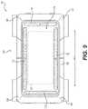
- FIG. 9depicts a top view of one example of an acoustic beam-steering array in an exterior safety system of an autonomous vehicle
- FIG. 10Adepicts top plan views of two examples of sensor coverage
- FIG. 10Bdepicts top plan views of another two examples of sensor coverage
- FIG. 11Adepicts one example of an acoustic beam-steering array in an exterior safety system of an autonomous vehicle
- FIG. 11Bdepicts one example of a flow diagram for implementing acoustic beam-steering in an autonomous vehicle
- FIG. 11Cdepicts a top plan view of one example of an autonomous vehicle steering acoustic energy associated with an acoustic alert to an object;
- FIG. 12Adepicts one example of a light emitter in an exterior safety system of an autonomous vehicle
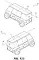
- FIG. 12Bdepicts profile views of examples of light emitters in an exterior safety system of an autonomous vehicle
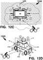
- FIG. 12Cdepicts a top plan view of one example of light emitter activation based on an orientation of an autonomous vehicle relative to an object
- FIG. 12Ddepicts a profile view of one example of light emitter activation based on an orientation of an autonomous vehicle relative to an object
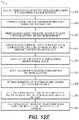
- FIG. 12Edepicts one example of a flow diagram for implementing a visual alert from a light emitter in an autonomous vehicle
- FIG. 12Fdepicts a top plan view of one example of a light emitter of an autonomous vehicle emitting light to implement a visual alert
- FIG. 13Adepicts one example of a bladder system in an exterior safety system of an autonomous vehicle
- FIG. 13Bdepicts examples of bladders in an exterior safety system of an autonomous vehicle
- FIG. 13Cdepicts examples of bladder deployment in an autonomous vehicle
- FIG. 14depicts one example of a seat belt tensioning system in an interior safety system of an autonomous vehicle
- FIG. 15depicts one example of a seat actuator system in an interior safety system of an autonomous vehicle
- FIG. 16Adepicts one example of a drive system in an autonomous vehicle
- FIG. 16Bdepicts one example of obstacle avoidance maneuvering in an autonomous vehicle.
- FIG. 16Cdepicts another example of obstacle avoidance maneuvering in an autonomous vehicle
- FIG. 17depicts examples of visual communication with an object in an environment using a visual alert from light emitters of an autonomous vehicle
- FIG. 18depicts another example of a flow diagram for implementing a visual alert from a light emitter in an autonomous vehicle
- FIG. 19depicts an example of visual communication with an object in an environment using a visual alert from light emitters of an autonomous vehicle
- FIG. 20depicts yet another example of a flow diagram for implementing a visual alert from a light emitter in an autonomous vehicle
- FIG. 21depicts profile views of other examples of light emitters positioned external to an autonomous vehicle
- FIG. 22depicts profile views of yet other examples of light emitters positioned external to an autonomous vehicle
- FIG. 23depicts examples of light emitters of an autonomous vehicle.
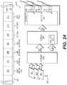
- FIG. 24depicts an example of data representing a light pattern associated with a light emitter of an autonomous vehicle.
- Non-transitory computer readable mediumSuch as a non-transitory computer readable medium or a computer network where the program instructions are sent over optical, electronic, or wireless communication links and stored or otherwise fixed in a non-transitory computer readable medium.
- Examples of a non-transitory computer readable mediumincludes but is not limited to electronic memory, RAM, DRAM, SRAM, ROM, EEPROM, Flash memory, solid-state memory, hard disk drive, and non-volatile memory, for example.
- One or more non-transitory computer readable mediumsmay be distributed over a number of devices. In general, operations of disclosed processes may be performed in an arbitrary order, unless otherwise provided in the claims.
- FIG. 1depicts one example of a system for implementing an active safety system in an autonomous vehicle.
- an autonomous vehicle 100(depicted in top plan view) may be travelling through an environment 190 external to the autonomous vehicle 100 along a trajectory 105 .
- environment 190may include one or more objects that may potentially collide with the autonomous vehicle 100 , such as static and/or dynamic objects, or objects that pose some other danger to passengers (not shown) riding in the autonomous vehicle 100 and/or to the autonomous vehicle 100 .
- objectsmay potentially collide with the autonomous vehicle 100 , such as static and/or dynamic objects, or objects that pose some other danger to passengers (not shown) riding in the autonomous vehicle 100 and/or to the autonomous vehicle 100 .
- FIG. 1depicts one example of a system for implementing an active safety system in an autonomous vehicle.
- an autonomous vehicle 100may be travelling through an environment 190 external to the autonomous vehicle 100 along a trajectory 105 .
- environment 190may include one or more objects that may potentially collide with the autonomous vehicle 100 , such as static and/
- an object 180e.g., an automobile
- a trajectory 185that if not altered (e.g., by changing trajectory, slowing down, etc.), may result in a potential collision 187 with the autonomous vehicle 100 (e.g., by rear-ending the autonomous vehicle 100 ).
- Autonomous vehicle 100may use a sensor system (not shown) to sense (e.g., using passive and/or active sensors) the environment 190 to detect the object 180 and may take action to mitigate or prevent the potential collision of the object 180 with the autonomous vehicle 100 .
- An autonomous vehicle system 101may receive sensor data 132 from the sensor system and may receive autonomous vehicle location data 139 (e.g., implemented in a localizer system of the autonomous vehicle 100 ).
- the sensor data 132may include but is not limited to data representing a sensor signal (e.g., a signal generated by a sensor of the sensor system).
- the data representing the sensor signalmay be indicative of the environment 190 external to the autonomous vehicle 100 .
- the autonomous vehicle location data 139may include but is not limited to data representing a location of the autonomous vehicle 100 in the environment 190 .
- the data representing the location of the autonomous vehicle 100may include position and orientation data (e.g., a local position or local pose), map data (e.g., from one or more map tiles), data generated by a global positioning system (GPS) and data generated by an inertial measurement unit (IMU).
- a sensor system of the autonomous vehicle 100may include a global positioning system, an inertial measurement unit, or both.
- Autonomous vehicle system 101may include but is not limited to hardware, software, firmware, logic, circuitry, computer executable instructions embodied in a non-transitory computer readable medium, or any combination of the foregoing, to implement a path calculator 112 , an object data calculator 114 (e.g., implemented in a perception system of the autonomous vehicle 100 ), a collision predictor 116 , an object classification determinator 118 and a kinematics calculator 115 .
- Autonomous vehicle system 101may access one or more data stores including but not limited to an objects type data store 119 .
- Object types data store 119may include data representing object types associated with object classifications for objects detected in environment 190 (e.g., a variety of pedestrian object types such as “sitting”, “standing” or “running”, may be associated with objects classified as pedestrians).
- Path calculator 112may be configured to generate data representing a trajectory of the autonomous vehicle 100 (e.g., trajectory 105 ), using data representing a location of the autonomous vehicle 100 in the environment 190 and other data (e.g., local pose data included in vehicle location data 139 ), for example. Path calculator 112 may be configured to generate future trajectories to be executed by the autonomous vehicle 100 , for example.
- path calculator 112may be implanted in or as part of a planner system of the autonomous vehicle 100 .
- the path calculator 112 and/or the planner systemmay calculate data associated with a predicted motion of an object in the environment and may determine a predicted object path associated with the predicted motion of the object.
- the object pathmay constitute the predicted object path.
- the object pathmay constitute a predicted object trajectory.
- the object path(e.g., in the environment) may constitute a predicted object trajectory that may be identical to or similar to a predicted object trajectory.
- Object data calculator 114may be configured to calculate data representing the location of the object 180 disposed in the environment 190 , data representing an object track associated with the object 180 , and data representing an object classification associated with the object 180 , and the like. Object data calculator 114 may calculate the data representing the location of the object, the data representing the object track, and the data representing the object classification using data representing a sensor signal included in sensor data 132 , for example. In some examples, the object data calculator 114 may be implemented in or may constitute a perception system, or a portion thereof, being configured to receive the data representing the sensor signal (e.g., a sensor signal from a sensor system).
- Object classification determinator 118may be configured to access data representing object types 119 (e.g., a species of an object classification, a subclass of an object classification, or a subset of an object classification) and may be configured to compare the data representing the object track and the data representing the object classification with the data representing the object types 119 to determine data representing an object type (e.g., a species or subclass of the object classification).
- object types 119e.g., a species of an object classification of a “car”
- An object typemay include additional subclasses or subsets such as a “school bus” that is parked may have an additional subclass of “static” (e.g. the school bus is not in motion), or an additional subclass of “dynamic” (e.g. the school bus is in motion), for example.
- Collision predictor 116may be configured to use the data representing the object type, the data representing the trajectory of the object and the data representing the trajectory of the autonomous vehicle to predict a collision (e.g., 187 ) between the autonomous vehicle 100 and the object 180 , for example.
- a collisione.g., 187
- a kinematics calculator 115may be configured to compute data representing one or more scalar and/or vector quantities associated with motion of the object 180 in the environment 190 , including but not limited to velocity, speed, acceleration, deceleration, momentum, local pose and force, for example. Data from kinematics calculator 115 may be used to compute other data including but not limited to data representing an estimated time to impact between the object 180 and the autonomous vehicle 100 and data representing a distance between the object 180 and the autonomous vehicle 100 , for example. In some examples the kinematics calculator 115 may be configured to predict a likelihood that other objects in the environment 190 (e.g.
- the kinematics calculator 115may be configured estimate a probability that other agents (e.g., drivers or riders of other vehicles) are behaving rationally (e.g., based on motion of the object they are driving or riding), which may dictate behavior of the autonomous vehicle 100 , versus behaving irrationally (e.g. based on erratic motion of the object they are riding or driving).
- agentse.g., drivers or riders of other vehicles
- behaving rationallye.g., based on motion of the object they are driving or riding
- behaving irrationallye.g. based on erratic motion of the object they are riding or driving
- Rational or irrational behaviormay be inferred based on sensor data received over time that may be used to estimate or predict a future location of the object relative to a current or future trajectory of the autonomous vehicle 100 . Consequently, a planner system of the autonomous vehicle 100 may be configured to implement vehicle maneuvers that are extra cautious and/or activate a safety system of the autonomous vehicle 100 , for example.
- a safety system activator 120may be configured to activate one or more safety systems of the autonomous vehicle 100 when a collision is predicted by the collision predictor 116 and/or the occurrence of other safety related events (e.g., an emergency maneuver by the vehicle 100 , such as hard braking, sharp acceleration, etc.).
- Safety system activator 120may be configured to activate an interior safety system 122 , an exterior safety system 124 , a drive system 126 (e.g., cause drive system 126 to execute an emergency maneuver to avoid the collision), or any combination of the foregoing.
- drive system 126may receive data being configured to cause a steering system (e.g., set a steering angle or a steering vector for the wheels) and a propulsion system (e.g., power supplied to an electric motor) to alter the trajectory of vehicle 100 from trajectory 105 to a collision avoidance trajectory 105 a.
- a steering systeme.g., set a steering angle or a steering vector for the wheels
- a propulsion systeme.g., power supplied to an electric motor
- FIG. 2Adepicts one example of a flow diagram 200 for implementing an active safety system in an autonomous vehicle 100 .
- data representing a trajectory 203 of an autonomous vehicle 100 in an environment external to the autonomous vehicle 100may be received (e.g., implemented in a planner system of the autonomous vehicle 100 ).
- object data associated with an objecte.g., automobile 180 disposed in the environment (e.g., environment 190 ) may be calculated.
- Sensor data 205may be accessed at the stage 204 to calculate the object data.
- the object datamay include but is not limited to data representing object location in the environment, an object track associated with the object (e.g., static for a non-moving object and dynamic for an object in motion), and an object classification (e.g., a label) associated with the object (e.g., pedestrian, dog, cat, bicycle, motorcycle, automobile, truck, etc.).
- the stage 204may output one or more types of data associated with an object, including but not limited to data representing object location 207 in the environment, data representing an object track 209 , and data representing an object classification 211 .
- a predicted object path of the object in the environmentmay be calculated.
- the stage 206may receive the data representing object location 207 and may process that data to generate data representing a predicted object path 213 .
- data representing object types 215may be accessed, and at a stage 210 , data representing an object type 217 may be determined based on the data representing the object track 209 , the data representing the object classification 211 and the data representing object types 215 .
- Examples of an object typemay include but are not limited to a pedestrian object type having a static object track (e.g., the pedestrian is not in motion), an automobile object type having a dynamic object track (e.g., the automobile is in motion) and an infrastructure object type having a static object track (e.g., a traffic sign, a lane marker, a fire hydrant), etc., just to name a few.
- the stage 210may output the data representing object type 217 .
- a collision between the autonomous vehicle and the objectmay be predicted based on the determined object type 217 , the autonomous vehicle trajectory 203 and the predicted object path 213 .
- a collisionmay be predicted based in part on the determined object type 217 due to the object having an object track that is dynamic (e.g., the object is in motion in the environment), the trajectory of the object being in potential conflict with a trajectory of the autonomous vehicle (e.g., the trajectories may intersect or otherwise interfere with each other), and the object having an object classification 211 (e.g., used in computing the object type 217 ) that indicates the object is a likely collision threat (e.g., the object is classified as an automobile, a skateboarder, a bicyclists, a motorcycle, etc.).
- object classification 211e.g., used in computing the object type 217
- a safety system of the autonomous vehiclemay be activated when the collision is predicted (e.g., at the stage 212 ).
- the stage 214may activate one or more safety systems of the autonomous vehicle, such as one or more interior safety systems, one or more exterior safety systems, one or more drive systems (e.g., steering, propulsion, braking, etc.) or a combination of the foregoing, for example.
- the stage 214may cause (e.g., by communicating data and/or signals) a safety system activator 220 to activate one or more of the safety systems of the autonomous vehicle 100 .
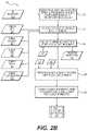
- FIG. 28depicts another example of a flow diagram 250 for implementing an active safety system in an autonomous vehicle 100 .
- data representing the trajectory 253 of an autonomous vehicle 100 in an environment external to the autonomous vehicle 100may be received (e.g., from a planner system of the autonomous vehicle 100 ).
- a location of an object in the environmentmay be determined.
- Sensor data 255may be processed (e.g., by a perception system) to determine data representing an object location in the environment 257 .
- Data associated with an objecte.g., object data associated with object 180
- the environmente.g., environment 190
- Sensor data 255 accessed at the stage 254may be used to determine the object data.
- the object datamay include but is not limited to data representing a location of the object in the environment, an object track associated with the object (e.g., static for a non-moving object and dynamic for an object in motion), an object classification associated with the object (e.g., pedestrian, dog, cat, bicycle, motorcycle, automobile, truck, etc.) and an object type associated with the object.
- the stage 254may output one or more types of data associated with an object, including but not limited to data representing the object location 257 in the environment, data representing an object track 261 associated with the object, data representing an object classification 263 associated with the object, and data representing an object type 259 associated with the object.
- a predicted object path of the object in the environmentmay be calculated.
- the stage 256may receive the data representing the object location 257 and may process that data to generate data representing a predicted object path 265 .
- the data representing the predicted object path 265 , generated at the stage 256may be used as a data input at another stage of flow diagram 250 , such as at a stage 258 .
- the stage 256may be bypassed and flow diagram 250 may transition from the stage 254 to the stage 258 .
- a collision between the autonomous vehicle and the objectmay be predicted based the autonomous vehicle trajectory 253 and the object location 265 .
- the object location 257may change from a first location to a next location due to motion of the object in the environment.
- the objectmay be in motion (e.g., has an object track of dynamic “O”), may be motionless (e.g., has an object track of static “5”), or both.
- the perception systemmay continually track the object (e.g., using sensor data from the sensor system) during those different points in time to determine object location 257 at the different point in times.
- the predicted object path 265 calculated at the stage 256may be difficult to determine; therefore the predicted object path 265 need not be used as a data input at the stage 258 .
- the stage 258may predict the collision using data not depicted in FIG. 28 , such as object type 259 and predicted object path 265 , for example.
- a collision between the autonomous vehicle and the objectmay be predicted based on the autonomous vehicle trajectory 253 , the object location 257 and the object type 259 .
- a collision between the autonomous vehicle and the objectmay be predicted based on the autonomous vehicle trajectory 253 and the predicted object path 265 .
- a collision between the autonomous vehicle and the objectmay be predicted based on the autonomous vehicle trajectory 253 , the predicted object path 265 and the object type 259 .
- a safety system of the autonomous vehiclemay be activated when the collision is predicted (e.g., at the stage 258 ).
- the stage 260may activate one or more safety systems of the autonomous vehicle, such as one or more interior safety systems, one or more exterior safety systems, one or more drive systems (e.g., steering, propulsion, braking, etc.) or a combination of the foregoing, for example.
- the stage 260may cause (e.g., by communicating data and/or signals) a safety system activator 269 to activate one or more of the safety systems of the autonomous vehicle.
- FIG. 2Cdepicts yet another example of a flow diagram 270 for implementing an active safety system in an autonomous vehicle.
- data representing the trajectory 273 of an autonomous vehicle 100 in an environment external to the autonomous vehicle 100may be received (e.g., from a planner system of the autonomous vehicle 100 ).
- a location of an object in the environmentmay be determined (e.g., by a perception system) using sensor data 275 , for example.
- the stage 274may generate data representing object location 279 .
- the data representing the object location 279may include data representing a predicted rate of motion 281 of the object relative to the location of the object in the environment. For example, if the object has a static object track indicative of no motion in the environment, then the predictive rate of motion 281 may be zero. However, if the object track of the object is dynamic and the object classification is an automobile, then the predicted rate of motion 281 may be non-zero.
- a predicted next location of the object in the environmentmay be calculated based on the predicted rate of motion 281 .
- the stage 276may generate data representing the predicted next location 283 .
- probabilities of impact between the object and the autonomous vehiclemay be predicted based on the predicted next location 283 and the autonomous vehicle trajectory 273 .
- the stage 278may generate data representing the probabilities of impact 285 .
- subsets of thresholds(e.g., a location or a distance in the environment) to activate different escalating functions of subsets of safety systems of the autonomous vehicle may be calculated based on the probabilities of impact 285 . At least one subset of the thresholds being associated with the activation of different escalating functions of a safety system of the autonomous vehicle.
- the stage 280may generate data representing one or more threshold subsets 287 .
- the subsets of thresholdsmay constitute a location relative to the autonomous vehicle or may constitute a distance relative to the autonomous vehicle.
- a thresholdmay be a function of a location or a range of locations relative to a reference location (e.g., the autonomous vehicle).
- a thresholdmay be a function of distance relative to an object and the autonomous vehicle, or between any objects or object locations, including distances between predicted object locations.
- one or more of the different escalating functions of the safety systemmay be activated based on an associated predicted probability (e.g., activation of a bladder based on a predicted set of probabilities of impact indicative of an eminent collision).
- the stage 282may cause (e.g., by communicating data and/or signals) a safety system activator 289 to activate one or more of the safety systems of the autonomous vehicle based on corresponding one or more sets of probabilities of collision.
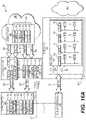
- FIG. 3Adepicts one example 300 of a system for implementing an active safety system in an autonomous vehicle.
- autonomous vehicle system 301may include a sensor system 320 including sensors 328 being configured to sense the environment 390 (e.g., in real-time or in near-real-time) and generate (e.g., in real-time) sensor data 332 and 334 (e.g., data representing a sensor signal).
- Autonomous vehicle system 301may include a perception system 340 being configured to detect objects in environment 390 , determine an object track for objects, classify objects, track locations of objects in environment 390 , and detect specific types of objects in environment 390 , such as traffic signs/lights, road markings, lane markings and the like, for example.
- Perception system 340may receive the sensor data 334 from a sensor system 320 .
- Autonomous vehicle system 301may include a localizer system 330 being configured to determine a location of the autonomous vehicle in the environment 390 .
- Localizer system 330may receive sensor data 332 from a sensor system 320 .
- sensor data 332 received by localizer system 330may not be identical to the sensor data 334 received by the perception system 340 .
- perception system 330may receive data 334 from sensors including but not limited to LIDAR (e.g., 20, 3D, color LIDAR), RADAR, and Cameras (e.g., image capture devices); whereas, localizer system 330 may receive data 332 including but not limited to global positioning system (GPS) data, inertial measurement unit (IMU) data, map data, route data, Route Network Definition File (RNDF) data and map tile data.
- Localizer system 330may receive data from sources other than sensor system 320 , such as a data store, data repository, memory, etc.
- sensor data 332 received by localizer system 330may be identical to the sensor data 334 received by the perception system 340 .
- localizer system 330 and perception system 340mayor may not implement similar or equivalent sensors or types of sensors. Further, localizer system 330 and perception system 340 each may implement any type of sensor data 332 independently of each other.
- Perception system 340may process sensor data 334 to generate object data 349 that may be received by a planner system 310 .
- Object data 349may include data associated with objects detected in environment 390 and the data may include but is not limited to data representing object classification, object type, object track, object location, predicted object path, predicted object trajectory, and object velocity, for example.
- Localizer system 330may process sensor data 334 , and optionally, other data, to generate position and orientation data, local pose data 339 that may be received by the planner system 310 .
- the local pose data 339may include, but is not limited to, data representing a location of the autonomous vehicle in the environment 390 , GPS data, I MU data, map data, route data, Route Network Definition File (RNDF) data, odometry data, wheel encoder data, and map tile data, for example.
- RDFRoute Network Definition File
- Planner system 310may process the object data 349 and the local pose data 339 to compute a path (e.g., a trajectory of the autonomous vehicle) for the autonomous vehicle through the environment 390 .
- the computed pathbeing determined in part by objects in the environment 390 that may create an obstacle to the autonomous vehicle and/or may pose a collision threat to the autonomous vehicle, for example.
- Planner system 310may be configured to communicate control and data 317 with one or more vehicle controllers 350 .
- Control and data 317may include information configured to control driving operations of the autonomous vehicle (e.g., steering, braking, propulsion, signaling, etc.) via a drive system 326 , to activate one or more interior safety systems 322 of the autonomous vehicle and to activate one or more exterior safety systems 324 of the autonomous vehicle.
- Drive system 326may perform additional functions associated with active safety of the autonomous vehicle, such as collision avoidance maneuvers, for example.
- Vehicle controller(s) 350may be configured to receive the control and data 317 , and based on the control and data 317 , communicate interior data 323 , exterior data 325 and drive data 327 to the interior safety system 322 , the exterior safety system 324 , and the drive system 326 , respectively, as determined by the control and data 317 , for example.
- control and data 317may include information configured to cause the vehicle controller 350 to generate interior data 323 to activate one or more functions of the interior safety system 322 .
- the autonomous vehicle system 301 and its associated systems 310 , 320 , 330 , 340 , 350 , 322 , 324 and 326may be configured to access data 315 from a data store 311 (e.g., a data repository) and/or data 312 from an external resource 313 (e.g., the Cloud, the Internet, a wireless network).
- the autonomous vehicle system 301 and its associated systems 310 , 320 , 330 , 340 , 350 , 322 , 324 and 326may be configured to access, in real-time, data from a variety of systems and/or data sources including but not limited to those depicted in FIG. 3A .
- localizer system 330 and perception system 340may be configured to access in real-time the sensor data 332 and the sensor data 334 .
- the planner system 310may be configured to access in real-time the object data 349 , the local pose data 339 and control and data 317 .
- the planner system 310may be configured to access in real-time the data store 311 and/or the external resource 313 .
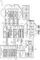
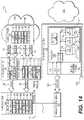
- FIG. 38depicts another example 399 of a system for implementing an active safety system in an autonomous vehicle.
- sensors 328 in sensor system 320may include but are not limited to one or more of: Light Detection and Ranging sensors 371 (LIDAR); image capture sensors 373 (e.g., Cameras); Radio Detection And Ranging sensors 375 (RADAR); sound capture sensors 377 (e.g., Microphones); Global Positioning System sensors (GPS) and/or Inertial Measurement Unit sensors (IMU) 379 ; and Environmental sensor(s) 372 (e.g., temperature, barometric pressure), for example.
- LIDARLight Detection and Ranging sensors 371
- image capture sensors 373e.g., Cameras
- Radio Detection And Ranging sensors 375RADAR
- sound capture sensors 377e.g., Microphones
- GPSGlobal Positioning System sensors
- IMUInertial Measurement Unit sensors
- Environmental sensor(s) 372e.g.
- Localizer system 330 and perception system 340may receive sensor data 332 and/or sensor data 334 , respectively, from one or more of the sensors 328 .
- perception system 340may receive sensor data 334 relevant to determine information associated with objects in environment 390 , such as sensor data from LIDAR 371 , Cameras 373 , RADAR 375 , Environmental 372 , and Microphones 377 ; whereas, localizer system 330 may receive sensor data 332 associated with the location of the autonomous vehicle in environment 390 , such as from GPS/IMU 379 .
- localizer system 330may receive data from sources other than the sensor system 320 , such as map data, map tile data, route data, Route Network Definition File (RNDF) data, a data store, a data repository, etc., for example.
- sensor data ( 332 , 334 ) received by localizer system 330may be identical to the sensor data ( 332 , 334 ) received by the perception system 340 .
- sensor data ( 332 , 334 ) received by localizer system 330may not be identical to the sensor data ( 332 , 334 ) received by the perception system 340 .
- Sensor data 332 and 334each may include data from any combination of one or more sensors or sensor types in sensor system 320 . The amounts and types of sensor data 332 and 334 may be independent from the other and mayor may not be similar or equivalent.
- localizer system 330may receive and/or access data from sources other than sensor data ( 332 , 334 ) such as odometry data 336 from motion sensors to estimate a change in position of the autonomous vehicle 100 over time, wheel encoders 337 to calculate motion, distance and other metrics of the autonomous vehicle 100 based on wheel rotations (e.g., by propulsion system 368 ), map data 335 from data representing map tiles, route data, Route Network Definition File (RNDF) data and/or others, and data representing an autonomous vehicle (A V) model 338 that may be used to calculate vehicle location data based on models of vehicle dynamics (e.g., from simulations, captured data, etc. ⁇ of the autonomous vehicle 100 .
- Localizer system 330may use one or more of the data resources depicted to generate data representing local pose data 339 .
- perception system 340may parse or otherwise analyze, process, or manipulate sensor data ( 332 , 334 ) to implement object detection 341 , object track 343 (e.g., determining which detected objects are static (no motion) and which are dynamic (in motion) ⁇ , object classification 345 (e.g., cars, motorcycle, bike, pedestrian, skate boarder, mailbox, buildings, street lights, etc.), object tracking 347 (e.g., tracking an object based on changes in a location of the object in the environment 390 ), and traffic light/sign detection 342 (e.g., stop lights, stop signs, rail road crossings, lane markers, pedestrian cross-walks, etc.).
- object detection 341e.g., object track 343 (e.g., determining which detected objects are static (no motion) and which are dynamic (in motion) ⁇ , object classification 345 (e.g., cars, motorcycle, bike, pedestrian, skate boarder, mailbox, buildings, street lights, etc.), object tracking 347 (e.g.,
- planner system 310may receive the local pose data 339 and the object data 349 and may parse or otherwise analyze, process, or manipulate data (local pose data 339 , object data 349 ) to implement functions including but not limited to trajectory calculation 381 , threshold location estimation 386 , audio signal selection 389 , light pattern selection 382 , kinematics calculation 384 , object type detection 387 , collision prediction 385 and object data calculation 383 , for example.
- Planner system 310may communicate trajectory and control data 317 to a vehicle controller(s) 350 .
- Vehicle controller(s ⁇ 350may process the vehicle control and data 317 to generate drive system data 327 , interior safety system data 323 and exterior safety system data 325 .
- Drive system data 327may be communicated to a drive system 326 .
- Drive system 326may communicate the drive system data 327 to a braking system 364 , a steering system 366 , a propulsion system 368 , and a signal system 362 (e.g., turn signals, brake signals, headlights, and running lights).
- drive system data 327may include steering angle data for steering system 366 (e.g., a steering angle for a wheel), braking data for brake system 364 (e.g., brake force to be applied to a brake pad), and propulsion data (e.g., a voltage, current or power to be applied to a motor) for propulsion system 368 .
- a dashed line 377may represent a demarcation between a vehicle trajectory processing layer and a vehicle physical execution layer where data processed in the vehicle trajectory processing layer is implemented by one or more of the drive system 326 , the interior safety system 322 or the exterior safety system 324 .
- one or more portions of the interior safety system 322may be configured to enhance the safety of passengers in the autonomous vehicle 100 in the event of a collision and/or other extreme event (e.g., a collision avoidance maneuver by the autonomous vehicle 100 ).
- one or more portions of the exterior safety system 324may be configured to reduce impact forces or negative effects of the aforementioned collision and/or extreme event.
- Interior safety system 322may have systems including but not limited to a seat actuator system 363 and a seat belt tensioning system 361 .
- Exterior safety system 324may have systems including but not limited to an acoustic array system 365 , a light emitter system 367 and a bladder system 369 .
- Drive system 326may have systems including but not limited to a braking system 364 , a signal system 362 , a steering system 366 and a propulsion system 368 .
- Systems in exterior safety system 324may be configured to interface with the environment 390 by emitting light into the environment 390 using one or more light emitters (not shown) in the light emitter system 367 , emitting a steered beam of acoustic energy (e.g., sound) into the environment 390 using one or more acoustic beam-steering arrays (not shown) in the acoustic beam-steering array 365 or by expanding one or more bladders (not shown) in the bladder system 369 from an un-deployed position to a deployed position, or any combination of the foregoing.
- a steered beam of acoustic energye.g., sound
- the acoustic beam-steering array 365may emit acoustic energy into the environment using transducers, air horns, or resonators, for example.
- the acoustic energymay be omnidirectional, or may constitute a steered beam, or otherwise focused sound (e.g., a directional acoustic source, a phased array, a parametric array, a large radiator, of ultrasonic source).
- systems in exterior safety system 324may be positioned at one or more locations of the autonomous vehicle 100 configured to allow the systems to interface with the environment 390 , such as a location associated with an external surface (e.g., 100 e in FIG. 1 ) of the autonomous vehicle 100 .
- Systems in interior safety system 322may be positioned at one or more locations associated with an interior (e.g., 100 i in FIG. 1 ) of the autonomous vehicle 100 and may be connected with one or more structures of the autonomous vehicle 100 , such as a seat, a bench seat, a floor, a rail, a bracket, a pillar, or other structure.
- the seat belt tensioning system 361 and the seat actuator system 363may be coupled with one or more structures configured to support mechanical loads that may occur due to a collision, vehicle acceleration, vehicle deceleration, evasive maneuvers, sharp turns, hard braking, etc., for example.
- FIG. 4depicts one example of a flow diagram 400 for implementing a perception system in an autonomous vehicle.
- sensor data 434e.g., generated by one or more sensors in sensor system 420
- perception system 440is depicted visually as sensor data 434 a - 434 c (e.g., LIDAR data, color LIDAR data, 3D LIDAR data).
- sensor data 434 a - 434 ce.g., LIDAR data, color LIDAR data, 3D LIDAR data.
- a determinationmay be made as to whether or not the sensor data 434 includes data representing a detected object. If a NO branch is taken, then flow diagram 400 may return to the stage 402 to continue analysis of sensor data 434 to detect object in the environment.
- flow diagram 400may continue to a stage 404 where a determination may be made as to whether or not the data representing the detected object includes data representing a traffic sign or light. If a YES branch is taken, then flow diagram 400 may transition to a stage 406 where the data representing the detected object may be analyzed to classify the type of light/sign object detected, such as a traffic light (e.g., red, yellow, and green) or a stop sign (e.g., based on shape, text and color), for example. Analysis at the stage 406 may include accessing a traffic object data store 424 where examples of data representing traffic classifications may be compared with the data representing the detected object to generate data representing a traffic classification 407 . The stage 406 may then transition to another stage, such as a stage 412 . In some examples, the stage 404 may be optional, and the stage 402 may transition to a stage 408 .
- a traffic lighte.g., red, yellow, and green
- a stop signe.g., based
- flow diagram 400may transition to the stage 408 where the data representing the detected object may be analyzed to determine other object types to be classified. If a YES branch is taken, then flow diagram 400 may transition to a stage 410 where the data representing the detected object may be analyzed to classify the type of object.
- An object data store 426may be accessed to compare stored examples of data representing object classifications with the data representing the detected object to generate data representing an object classification 411 .
- the stage 410may then transition to another stage, such as a stage 412 . If a NO branch is taken from the stage 408 , then stage 408 may transition to another stage, such as back to the stage 402 .
- object data classified at the stages 406 and/or 410may be analyzed to determine if the sensor data 434 indicates motion associated with the data representing the detected object. If motion is not indicated, then a NO branch may be taken to a stage 414 where data representing an object track for the detected object may be set to static (5).
- data representing a location of the objecte.g., the static object
- the data representing the location of the objectmay be included in data received by the planner system (e.g., planner system 310 in FIG. 38 ).
- the planner systemmay use the data representing the location of the object to determine a coordinate of the object (e.g., a coordinate relative to autonomous vehicle 100 ).
- a YES branchmay be taken to a stage 418 where data representing an object track for the detected object may be set to dynamic (0).
- data representing a location of the objecte.g., the dynamic object
- the planner systemmay analyze the data representing the object track and/or the data representing the location of the object to determine if a detected object (static or dynamic) may potentially have a conflicting trajectory with respect to the autonomous vehicle and/or come into too close a proximity of the autonomous vehicle, such that an alert (e.g., from a light emitter and/or from an acoustic beam-steering array) may be used to alter a behavior of the object and/or the person controlling the object.
- an alerte.g., from a light emitter and/or from an acoustic beam-steering array
- one or more of the data representing the object classification, the data representing the object track, and the data representing the location of the objectmay be included with the object data 449 (e.g., the object data received by the planner system).
- sensor data 434 amay include data representing an object (e.g., a person riding a skateboard).
- Stage 402may detect the object in the sensor data 434 a .
- itmay be determined that the detected object is not a traffic sign/light.
- the stage 408may determine that the detected object is of another class and may analyze at a stage 410 , based on data accessed from object data store 426 , the data representing the object to determine that the classification matches a person riding a skateboard and output data representing the object classification 411 .
- a determinationmay be made that the detected object is in motion and at the stage 418 the object track may be set to dynamic (0) and the location of the object may be tracked at the stage 419 (e.g., by continuing to analyze the sensor data 434 a for changes in location of the detected object).
- the object data associated with sensor data 434may include the classification (e.g., a person riding a skateboard), the object track (e.g., the object is in motion), the location of the object (e.g., the skateboarder) in the environment external to the autonomous vehicle) and object tracking data for example.
- the classificatione.g., a person riding a skateboard
- the object tracke.g., the object is in motion
- the location of the objecte.g., the skateboarder
- object tracking datafor example.
- flow diagram 400may determine that the object classification is a pedestrian, the pedestrian is in motion (e.g., is walking) and has a dynamic object track, and may track the location of the object (e.g., the pedestrian) in the environment, for example.
- sensor data 434 cflow diagram 400 may determine that the object classification is a fire hydrant, the fire hydrant is not moving and has a static object track, and may track the location of the fire hydrant.
- the object data 449 associated with sensor data 434 a , 434 b , and 434 cmay be further processed by the planner system based on factors including but not limited to object track, object classification and location of the object, for example.
- the object data 449may be used for one or more of trajectory calculation, threshold location estimation, motion prediction, location comparison, and object coordinates, in the event the planner system decides to implement an alert (e.g., by an exterior safety system) for the skateboarder and/or the pedestrian.
- an alerte.g., by an exterior safety system
- the planner systemmay decide to ignore the object data for the fire hydrant due its static object track because the fire hydrant is not likely to have a motion (e.g., it is stationary) that will conflict with the autonomous vehicle and/or because the fire hydrant is non-animate (e.g., can't respond to or be aware of an alert, such as emitted light and/or beam steered sound), generated by an exterior safety system of the autonomous vehicle), for example.
- an alertsuch as emitted light and/or beam steered sound
- FIG. 5depicts one example 500 of object prioritization by a planner system in an autonomous vehicle.
- Example 500depicts a visualization of an environment 590 external to the autonomous vehicle 100 as sensed by a sensor system of the autonomous vehicle 100 (e.g., sensor system 320 of FIG. 38 ).
- Object data from a perception system of the autonomous vehicle 100may detect several objects in environment 590 including but not limited to an automobile 581 d , a bicycle rider 583 d , a walking pedestrian 585 d , and two parked automobiles 5875 and 5895 .
- a perception systemmay have assigned (e.g., based on sensor data 334 of FIG.
- the perception systemmay also have assigned (e.g., based on sensor data 334 of FIG. 38 ) static “5” object tracks to objects 5875 and 5895 , thus the label “5” is associated with the reference numerals for those objects.
- a localizer system of the autonomous vehiclemay determine the local pose data 539 for a location of the autonomous vehicle 100 in environment 590 (e.g., X, Y, Z coordinates relative to a location on vehicle 100 or other metric or coordinate system).
- the local pose data 539may be associated with a center of mass (not shown) or other reference point of the autonomous vehicle 100 .
- autonomous vehicle 100may have a trajectory T AV as indicated by the arrow.
- the two parked automobiles 5875 and 5895are static and have no indicated trajectory.
- Bicycle rider 583 dhas a trajectory Tb that is in a direction approximately opposite that of the trajectory Tav, and automobile 581 d has a trajectory Tmv that is approximately parallel to and in the same direction as the trajectory Tav.
- Pedestrian 585 dhas a trajectory Tp that is predicted to intersect the trajectory Tav of the vehicle 100 .
- Motion and/or position of the pedestrian 585 d in environment 590 or other objects in the environment 590may be tracked or otherwise determined using metrics other than trajectory, including but not limited to object location, predicted object motion, object coordinates, predictive rate of motion relative to the location of the object, and a predicted next location of the object, for example.
- Motion and/or position of the pedestrian 585 d in environment 590 or other objects in the environment 590may be determined, at least in part, due to probabilities.
- the probabilitiesmay be based on data representing object classification, object track, object location, and object type, for example. In some examples, the probabilities may be based on previously observed data for similar objects at a similar location. Further, the probabilities may be influenced as well by time of day or day of the week, or other temporal units, etc. As one example, the planner system may learn that between about 3:00 pm and about 4:00 pm, on weekdays, pedestrians at a given intersection are 85% likely to cross a street in a particular direction.
- the planner systemmay place a lower priority on tracking the location of static objects 5875 and 5895 and dynamic object 583 d because the static objects 5875 and 5895 are positioned out of the way of trajectory Tav (e.g., objects 5875 and 5895 are parked) and dynamic object 583 d (e.g., an object identified as a bicyclist) is moving in a direction away from the autonomous vehicle 100 ; thereby, reducing or eliminating a possibility that trajectory Tb of object 583 d may conflict with trajectory Tav of the autonomous vehicle 100 .
- trajectory Tave.g., objects 5875 and 5895 are parked
- dynamic object 583 de.g., an object identified as a bicyclist
- the planner systemmay place a higher priority on tracking the location of pedestrian 585 d due to its potentially conflicting trajectory Tp, and may place a slightly lower priority on tracking the location of automobile 581 d because its trajectory Tmv is not presently conflicting with trajectory Tav, but it may conflict at a later time (e.g., due to a lane change or other vehicle maneuver).
- pedestrian object 585 dmay be a likely candidate for an alert (e.g., using steered sound and/or emitted light) or other safety system of the autonomous vehicle 100 , because the path of the pedestrian object 585 d (e.g., based on its location and/or predicted motion) may result in a potential collision (e.g., at an estimated location 560 ) with the autonomous vehicle 100 or result in an unsafe distance between the pedestrian object 585 d and the autonomous vehicle 100 (e.g., at some future time and/or location).
- a priority placed by the planner system on tracking locations of objectsmay be determined, at least in part, on a cost function of trajectory generation in the planner system.
- Objects that may be predicted to require a change in trajectory of the autonomous vehicle 100may be factored into the cost function with greater significance as compared to objects that are predicted to not require a change in trajectory of the autonomous vehicle 100 , for example.
- the planner systemmay predict one or more regions of probable locations 565 of the object 585 d in environment 590 based on predicted motion of the object 585 d and/or predicted location of the object.
- the planner systemmay estimate one or more threshold locations (e.g., threshold boundaries) within each region of probable locations 565 .
- the threshold locationmay be associated with one or more safety systems of the autonomous vehicle 100 .
- the number, distance and positions of the threshold locationsmay be different for different safety systems of the autonomous vehicle 100 .
- a safety system of the autonomous vehicle 100may be activated at a parametric range in which a collision between an object and the autonomous vehicle 100 is predicted.
- the parametric rangemay have a location within the region of probable locations (e.g., within 565 ).
- the parametric rangemay be based in part on parameters such as a range of time and/or a range of distances. For example, a range of time and/or a range of distances in which a predicted collision between the object 585 d and the autonomous vehicle 100 may occur.
- being a likely candidate for an alert by a safety system of the autonomous vehicle 100does not automatically result in an actual alert being issued (e.g., as determine by the planner system).
- am objectmay be a candidate when a threshold is met or surpassed.
- a safety system of the autonomous vehicle 100may issue multiple alerts to one or more objects in the environment external to the autonomous vehicle 100 .
- the autonomous vehicle 100may not issue an alert even though an object has been determined to be a likely candidate for an alert (e.g., the planner system may have computed an alternative trajectory, a safe-stop trajectory or a safe-stop maneuver that obviates the need to issue an alert).
- the planner systemmay have computed an alternative trajectory, a safe-stop trajectory or a safe-stop maneuver that obviates the need to issue an alert.
- FIG. 6depicts a top plan view of one example 600 of threshold locations and associated escalating alerts in an active safety system in an autonomous vehicle.
- the example 500 of FIG. 5is further illustrated in top plan view where trajectory Tav and Tp are estimated to cross (e.g., based on location data for the vehicle 100 and the pedestrian object 585 d ) at an estimated location denoted as 560 .
- Pedestrian object 585 dis depicted in FIG. 6 based on pedestrian object 585 d being a likely candidate for an alert (e.g., visual and/or acoustic) based on its predicted motion.
- the pedestrian object 585 dis depicted having a location that is within the region of probable locations 565 that was estimated by the planner system.
- Autonomous vehicle 100may be configured to travel bi-directionally as denoted by arrow 680 , that is, autonomous vehicle 100 may not have a front (e.g., a hood) or a back (e.g., a trunk) as in a conventional automobile.
- FIG. 6 and other figuresmay describe implementations as applied to bidirectional vehicles, the functions and/or structures need not be so limiting and may be applied to any vehicle, including unidirectional vehicles.
- sensors of the sensor system and safety systemsmay be positioned on vehicle 100 to provide sensor and alert coverage in more than one direction of travel of the vehicle 100 and/or to provide sensor and alert coverage for objects that approach the vehicle 100 from its sides 1005 (e.g., one or more sensors 328 in sensor system 330 in FIG. 38 may include overlapping regions of sensor coverage).
- the planner systemmay implement a safe-stop maneuver or a safe-stop trajectory using the bi-directional 680 travel capabilities to avoid a collision with an object, for example.
- the autonomous vehicle 100may be traveling in a first direction, come to a stop, and begin travel in a second direction that is opposite the first direction, and may maneuver to a safe-stop location to avoid a collision or other extreme event.
- the planner systemmay estimate one or more threshold locations (e.g., threshold boundaries, which may be functions of distances, etc.) in the environment 590 , denoted as 601 , 603 and 605 , at which to issue an alert when the location of the object (e.g., pedestrian object 585 d ) coincides with the threshold locations as denoted by points of coincidence 602 , 604 and 606 .
- threshold locationse.g., threshold boundaries, which may be functions of distances, etc.
- planner systemmay determine the location of the pedestrian object 585 d at the point 602 (e.g., having coordinates X1, Y1 of either a relative or an absolute reference frame) and the coordinates of a location of the autonomous vehicle 100 (e.g., from local pose data).
- the location data for the autonomous vehicle 100 and the objectmay be used to calculate a location (e.g., coordinates, an angle, a polar coordinate) for the direction of propagation (e.g., a direction of the main lobe or focus of the beam) of a beam of steered acoustic energy (e.g., an audio alert) emitted by an acoustic beam-steering array (e.g., one or more of a directional acoustic source, a phased array, a parametric array, a large radiator, a ultrasonic source, etc.), may be used to determine which light emitter to activate for a visual alert, may be used to determine which bladder(s) to activate prior to a predicted collision with an object, and may be used to activate other safety systems and/or the drive system of the autonomous vehicle 100 , or any combination of the foregoing.
- a locatione.g., coordinates, an angle, a polar coordinate
- a locatione.g.
- the relative locations of the pedestrian object 585 d and the autonomous vehicle 100may change, such that at the location L 2 , the object 585 d has coordinates (X2, Y2) at point 604 of the second threshold location 603 .
- continued travel in the direction 625 along trajectory Tav, from location L 2 to location L 3may change the relative locations of the pedestrian object 585 d and the autonomous vehicle 100 , such that at the location L 3 , the object 585 d has coordinates (X3, Y3) at point 606 of the third threshold location 605 .
- the data representing the alert selected for a safety systemmay be different to convey an increasing sense of urgency (e.g., an escalating threat level) to the pedestrian object 585 d to change or halt its trajectory Tp, or otherwise modify his/her behavior to avoid a potential collision or close pass with the vehicle 100 .
- the data representing the alert selected for threshold location 601when the vehicle 100 may be at a relatively safe distance from the pedestrian object 585 d , may be a less alarming nonthreatening alert a 1 configured to garner the attention of the pedestrian object 585 d in a non-threatening manner.
- the data representing the alert selected for threshold location 603when the vehicle 100 may be at a cautious distance from the pedestrian object 585 d , may be a more aggressive urgent alert a 2 configured to gain the attention of the pedestrian object 585 d in a more urgent manner.
- the data representing the alert selected for threshold location 605when the vehicle 100 may be at a potentially un-safe distance from the pedestrian object 585 d , may be a very aggressive extremely urgent alert a 3 configured to gain the attention of the pedestrian object 585 d in an extremely urgent manner.
- the data representing the alertsmay be configured to convey an increasing escalation of urgency to pedestrian object 585 d (e.g., escalating acoustic and/or visual alerts to gain the attention of pedestrian object 585 d ).
- Estimation of positions of the threshold locations in the environment 590may be determined by the planner system to provide adequate time (e.g., approximately 5 seconds or more), based on a velocity of the autonomous vehicle, before the vehicle 100 arrives at a predicted impact point 560 with the pedestrian object 585 d (e.g., a point 560 in environment 590 where trajectories Tav and Tp are estimated to intersect each other).
- Point 560may change as the speed and/or location of the object 585 d , the vehicle 100 , or both changes.
- the planner system of the autonomous vehicle 100may be configured to actively attempt to avoid potential collisions (e.g., by calculating alternative collision avoidance trajectories and executing one or more of those trajectories) by calculating (e.g., continuously) safe trajectories (e.g., when possible based on context), while simultaneously, issuing alerts as necessary to objects in the environment when there is a meaningful probability the objects may collide or otherwise pose a danger to the safety of passengers in the autonomous vehicle 100 , to the object, or both.
- active alertse.g., acoustic and/or visual alerts
- the planner system of the autonomous vehicle 100may be configured to actively attempt to avoid potential collisions (e.g., by calculating alternative collision avoidance trajectories and executing one or more of those trajectories) by calculating (e.g., continuously) safe traject
- trajectory Tp of the pedestrian object 585 dneed not be a straight line as depicted and the trajectory (e.g., the actual trajectory) may be an arcuate trajectory as depicted in example 650 or may be a non-linear trajectory as depicted in example 670 .
- Points 652 , 654 and 656 in example 650 and points 672 , 674 and 676 in example 670depict points where the trajectory Tp intersects threshold locations 651 , 653 and 655 and threshold locations 671 , 673 and 675 , respectively.
- the planner systemmay process object data from the perception system and local pose data from the localizer system to calculate the threshold location(s).
- threshold locations601 , 603 and 605 in example 600 are aligned approximately perpendicular to the trajectory Tp of pedestrian object 585 d ; however, other configurations and orientations may be calculated and implemented by the planner system (e.g., see examples 650 and 670 ). As another example, threshold locations may be aligned approximately perpendicular (or other orientation) to the trajectory Tav of the autonomous vehicle 100 .
- the trajectory of the objectmay be analyzed by the planner system to determine the configuration of the threshold location(s).
- the threshold location(s)may have an arcuate profile and may be aligned with the trajectory of the object.
- FIG. 7depicts one example of a flow diagram 700 for implementing a planner system in an autonomous vehicle.
- planner system 710may be in communication with a perception system 740 from which it receives object data 749 , and a localizer system 730 from which it receives local pose data 739 .
- Object data 749may include data associated with one or more detected objects.
- object data 749may include data associated with a large number of detected objects in the environment external to the autonomous vehicle 100 .
- some detected objectsneed not be tracked or may be assigned a lower priority based on the type of object. For example, fire hydrant object 434 c in FIG.
- skateboarder object 434 amay require processing for an alert (e.g., using emitted light, steered sound or both) due to it being a dynamic object and other factors, such as predicted human behavior of skateboard riders, a location of the skateboarder object 434 a in the environment that may indicate the location (e.g., a predicted location) may conflict with a trajectory of the autonomous vehicle 100 , for example.
- an example of three detected objectsis denoted as 734 a - 734 c .
- the object data for each detected objectmay include but is not limited to data representing: object location 721 ; object classification 723 ; and object track 725 .
- Planner system 710may be configured to implement object type determination 731 .
- Object type determination 731may be configured to receive the data representing object classification 723 , the data representing the object track 725 and data representing object types that may be accessed from an object types data store 724 .
- the object type determination 731may be configured to compare the data representing the object classification 723 and the data representing the object track 725 with data representing object types (e.g., accessed from data store 724 ) to determine data representing an object type 733 .
- data representing an object type 733may include but are not limited to a static grounded object type (e.g., the fire hydrant 434 c of FIG. 4 ) and a dynamic pedestrian object (e.g., pedestrian object 585 d of FIG. 5 ).
- Object dynamics determination 735may be configured to receive the data representing the object type 733 and the data representing the object location 721 . Object dynamics determination 735 may be further configured to access an object dynamics data store 726 . Object dynamics data store 726 may include data representing object dynamics. Object dynamics determination 735 may be configured to compare data representing object dynamics with the data representing the object type 733 and the data representing the object location 721 to determine data representing a predicted object motion 737 .
- Object location predictor 741may be configured to receive the data representing the predicted object motion 737 , the data representing the location of the autonomous vehicle 743 (e.g., from local pose data 739 ), the data representing the object location 721 and the data representing the object track 725 .
- the object location predictor 741may be configured to process the received data to generate data representing a predicted object location 745 in the environment.
- Object location predictor 741may be configured to generate data representing more than one predicted object location 745 .
- the planner system 710may generate data representing regions of probable locations (e.g., 565 in FIGS. 5 and 6 ) of an object.
- Threshold location estimator 747may be configured to receive the data representing the location of the autonomous vehicle 743 (e.g., from local pose data 739 ) and the data representing the predicted object location 745 and generate data representing one or more threshold locations 750 in the environment associated with an alert to be triggered (e.g., a visual alert and/or an acoustic alert), or associated with activation of one or more safety systems of vehicle 100 , for example.
- the one or more threshold locations 750may be located with the regions of probable locations (e.g., 601 , 603 and 605 within 565 in FIG. 6 ).
- FIG. 8depicts one example 800 of a block diagram of systems in an autonomous vehicle.
- the autonomous vehicle 100may include a suite of sensors 820 positioned at one or more locations on the autonomous vehicle 100 .
- Each suite 820may have sensors including but not limited to LIDAR 821 (e.g., color LIDAR, three-dimensional color LIDAR, two-dimensional LIDAR, etc.), an image capture device 823 (e.g., a digital camera), RADAR 825 , a microphone 827 (e.g., to capture ambient sound), and a loudspeaker 829 (e.g., to greet/communicate with passengers of the AV 100 ).
- LIDAR 821e.g., color LIDAR, three-dimensional color LIDAR, two-dimensional LIDAR, etc.
- an image capture device 823e.g., a digital camera
- RADAR 825e.g., a microphone
- microphone 827e.g., to capture ambient sound
- Microphones 871(e.g., to may be configured to capture sound from drive system components such as propulsion systems and/or braking systems) and may be positioned at suitable locations proximate to drive system components to detect sound generated by those components, for example.
- Each suite of sensors 820may include more than one of the same types of sensor, such as two image capture devices 823 , or microphone 871 positioned proximate to each wheel 852 , for example.
- Microphone 871may be configured to capture audio signals indicative of drive operations of the autonomous vehicle 100 .
- Microphone 827may be configured to capture audio signals indicative of ambient sounds in the environment external to the autonomous vehicle 100 .
- Autonomous vehicle 100may include sensors for generating data representing location of the autonomous vehicle 100 , and those sensors may include but are not limited to a global positioning system (GPS) 839 a and/or an inertial measurement unit (IMU) 839 b .
- GPSglobal positioning system
- IMUinertial measurement unit
- Autonomous vehicle 100may include one or more sensors ENV 877 for sensing environmental conditions in the environment external to the autonomous vehicle 100 , such as air temperature, air pressure, humidity, barometric pressure, etc.
- Data generated by sensor(s ⁇ ENV 877may be used to calculate the speed of sound in processing of data used by array(s ⁇ 102 (see arrays 102 depicted in FIG. 9 ), such as wave front propagation times, for example.
- Autonomous vehicle 100may include one or more sensors MOT 888 configured to detect motion of the vehicle 100 (e.g., motion due to an impact from a collision, motion due to an emergency/evasive maneuvering, etc.).
- sensor MOT 888may include but is not limited to an accelerometer, a multi-axis accelerometer and a gyroscope.
- Autonomous vehicle 100may include one or more rotation sensors (not shown) associated with wheels 852 and configured to detect rotation 853 of the wheel 852 (e.g., a wheel encoder).
- each wheel 852may have an associated wheel encoder configured to detect rotation of the wheel 852 (e.g., an axle of the wheel 852 and/or a propulsion component of the wheel 852 , such as an electric motor, etc.).
- Data representing a rotation signal generated by the rotation sensormay be received by one or more systems of the autonomous vehicle 100 , such as the planner system, the localizer system, the perception system, the drive system, and one or more of the safety systems, for example.
- a communications network 815may route signals and/or data to/from sensors, one or more safety systems 875 (e.g., a bladder, a seat actuator, a seat belt tensioner), and other components of the autonomous vehicle 100 , such as one or more processors 810 and one or more routers 830 , for example.
- one or more safety systems 875e.g., a bladder, a seat actuator, a seat belt tensioner
- other components of the autonomous vehicle 100such as one or more processors 810 and one or more routers 830 , for example.
- Routers 830may route signals and/or data from: sensors in sensors suites 820 , one or more acoustic beam-steering arrays 102 (e.g., one or more of a directional acoustic source, a phased array, a parametric array, a large radiator, of ultrasonic source), one or more light emitters, between other routers 830 , between processors 810 , drive operation systems such as propulsion (e.g., electric motors 851 ), steering, braking, one or more safety systems 875 , etc., and a communications system 880 (e.g., for wireless communication with external systems and/or resources).
- acoustic beam-steering arrays 102e.g., one or more of a directional acoustic source, a phased array, a parametric array, a large radiator, of ultrasonic source
- drive operation systemssuch as propulsion (e.g., electric motors 851 ), steering, braking, one
- one or more microphones 827may be configured to capture ambient sound in the environment 890 external to the autonomous vehicle 100 . Signals and/or data from microphones 827 may be used to adjust gain values for one or more speakers positioned in one or more of the acoustic beam-steering arrays (not shown). As one example, loud ambient noise, such as emanating from a construction site may mask or otherwise impair audibility of the beam of steered acoustic energy 104 being emitted by an acoustic beam-steering array. Accordingly, the gain may be increased or decreased based on ambient sound (e.g., in dB or other metric such as frequency content).
- Microphones 871may be positioned in proximity of drive system components, such as electric motors 851 , wheels 852 , or brakes (not shown) to capture sound generated by those systems, such as noise from rotation 853 , regenerative braking noise, tire noise, and electric motor noise, for example.
- Signals and/or data generated by microphones 871may be used as the data representing the audio signal associated with an audio alert, for example.
- signals and/or data generated by microphones 871may be used to modulate the data representing the audio signal.
- the data representing the audio signalmay constitute an audio recording (e.g., a digital audio file) and the signals and/or data generated by microphones 871 may be used to modulate the data representing the audio signal.
- the signals and/or data generated by microphones 871may be indicative of a velocity of the vehicle 100 and as the vehicle 100 slows to a stop at a pedestrian cross-walk, the data representing the audio signal may be modulated by changes in the signals and/or data generated by microphones 871 as the velocity of the vehicle 100 changes.
- the signals and/or data generated by microphones 871 that are indicative of the velocity of the vehicle 100may be used as the data representing the audio signal and as the velocity of the vehicle 100 changes, the sound being emitted by the acoustic beam-steering array 102 may be indicative of the change in velocity of the vehicle 100 .
- the soundmay be changed (e.g., in volume, frequency, etc.) based on velocity changes.
- the above examplesmay be implemented to audibly notify pedestrians that the autonomous vehicle 100 has detected their presence at the cross-walk and is slowing to a stop.
- One or more processors 810may be used to implement one or more of the planner system, the localizer system, the perception system, one or more safety systems, and other systems of the vehicle 100 , for example.
- One or more processors 810may be configured to execute algorithms embodied in a non-transitory computer readable medium, to implement one or more of the planner system, the localizer system, the perception system, one or more safety systems, or other systems of the vehicle 100 , for example.
- the one or more processors 810may include but are not limited to circuitry, logic, field programmable gate array (FPGA), application specific integrated circuits (ASIC), programmable logic, a digital signal processor (DSP), a graphics processing unit (GPU), a microprocessor, a microcontroller, a big fat computer (BFC) or others, or clusters thereof.
- FPGAfield programmable gate array
- ASICapplication specific integrated circuits
- DSPdigital signal processor
- GPUgraphics processing unit
- microprocessora microcontroller
- BFCbig fat computer
- FIG. 9depicts a top view of one example 900 of an acoustic beam-steering array in an exterior safety system of an autonomous vehicle.
- sensor suitese.g., 820 in FIG. 8
- enclosures for acoustic beam-steering arrays 102may be positioned on an upper surface 100 u (e.g., on a roof or other locations on the vehicle) of the autonomous vehicle 100 and may be positioned to direct their respective beams of steered acoustic energy 104 (e.g., see FIG.
- Acoustic beam-steering arrays 102may be configured to provide coverage of steered acoustic energy at one or more objects disposed in the environment external to the autonomous vehicle 100 and the coverage may be in an arc of about 360 degrees around the autonomous vehicle 100 , for example.
- the acoustic beam-steering arrays 102need not be the same size, shape, or have the same number of speakers.
- the acoustic beam-steering arrays 102need not be linear as depicted in FIG. 9 .
- acoustic beam-steering arrays 102 denoted as C and Dhave different dimensions than acoustic beam-steering arrays 102 denoted as A and B.
- Sensor suites 820may be positioned to provide sensor coverage of the environment external to the autonomous vehicle 100 for one acoustic beam-steering array 102 or multiple acoustic beam-steering arrays 102 . In the case of multiple acoustic beam-steering arrays 102 , the sensor suites 820 may provide overlapping regions of sensor coverage.
- a perception system of the autonomous vehicle 100may receive sensor data from more than one sensor or suite of sensors to provide data for the planning system to implement activation of one or more of the arrays 102 to generate an acoustic alert and/or to activate one or more other safety systems of vehicle 100 , for example.
- the autonomous vehicle 100may not have a front (e.g., a hood) or a rear (e.g., a trunk) and therefore may be configured for driving operations in at least two different directions as denoted by arrow 980 .
- the acoustic beam-steering arrays 102may not have a front or rear designation and depending on which direction the autonomous vehicle 100 is driving in, array 102 (A) may be the array facing the direction of travel or array 102 (B) may be the array facing the direction of travel.
- Other safety systems of the autonomous vehicle 100may be disposed at interior 100 i (shown in dashed line) and exterior 100 e locations on the autonomous vehicle 100 and may be activated for generating alerts or other safety functions by the planner system using the sensor data from the sensor suites.
- the overlapping regions of sensor coveragemay be used by the planner system to activate one or more safety systems in response to multiple objects in the environment that may be positioned at locations around the autonomous vehicle 100 .
- FIGS. 10A-10Bdepicts top plan views of examples of sensor coverage.
- one of the four sensor suites 820may provide sensor coverage 1011 , using one or more of its respective sensors, of the environment 1090 in a coverage region that may be configured to provide sensor data for one or more systems, such as a perception system, localizer system, planner system and safety systems of the autonomous vehicle 100 , for example.
- arrows A, B, C and Ddemarcate four quadrants 1 - 4 that surround the autonomous vehicle 100 .
- sensor coverage 1011 by a single suite 820may be partial sensor coverage because there may be partial sensor blind spots not covered by the single suite 820 in quadrants 1 , 3 and 4 , and full sensor coverage in quadrant 2 .
- a second of the four sensor suites 820may provide sensor coverage 1021 that overlaps with sensor coverage 1011 , such that there may be partial sensor coverage in quadrants 1 and 4 and full sensor coverage in quadrants 2 and 3 .
- a third of the four sensor suites 820may provide sensor coverage 1031 that overlaps with sensor coverage 1011 and 1021 , such that quadrants 2 , 3 and 4 have full sensor coverage and quadrant 1 has partial coverage.
- a fourth of the four sensor suites 820may provide sensor coverage 1041 that overlaps with sensor coverage 1011 , 1021 and 1031 , such that quadrants 1 - 4 have full coverage.
- the overlapping sensor regions of coveragemay allow for redundancy in sensor coverage if one or more sensor suites 820 and/or one or more of their respective sensors (e.g., LIDAR, Camera, RADAR, etc.) are damaged, malfunction, or are otherwise rendered inoperative.
- One or more of the sensor coverage patterns 1011 , 1021 , 1031 and 1041may allow the planner system to implement activation of one or more safety systems based on the position of those safety systems on the autonomous vehicle 100 .
- bladders of a bladder safety system positioned on a side of the autonomous vehicle 100may be activated to counter a collision from an object approaching the vehicle 100 from the side.
- FIG. 11Adepicts one example of an acoustic beam-steering array in an exterior safety system of an autonomous vehicle.
- control data 317 from planner system 310may be communicated to vehicle controller 350 which may in turn communicate exterior data 325 being configured to implement an acoustic alert by acoustic beam-steering array 102 .
- vehicle controller 350may in turn communicate exterior data 325 being configured to implement an acoustic alert by acoustic beam-steering array 102 .
- the autonomous vehicle 100may include more than one array 102 as denoted by 1103 (e.g., see arrays 102 in FIG. 9 ).
- Exterior data 325 received by array 102may include but is not limited to object location data 1148 (e.g., a coordinate of object 1134 in the environment 1190 ), audio signal data 1162 , trigger signal data 1171 and optionally, modulation signal data 1169 .
- Acoustic beam-steering array 102may include a processor 1105 (e.g., a digital signal processor (DSP), field programmable gate array (FPGA), central processing unit (CPU), microprocessor, micro-controller, GPU's and/or clusters thereof, or other embedded processing system) that receives the exterior data 325 and processes the exterior data 325 to generate the beam 104 of steered acoustic energy (e.g., at angle J 3 relative to a trajectory T AV of AV 100 ) into the environment 1190 (e.g., in response to receiving the data representing the trigger signal 1171 ).
- Acoustic beam-steering array 102may include several speakers 5 , with each speaker 5 in the array 102 being coupled with an output of amplifier A.
- Each amplifier Amay include a gain input and a signal input.
- Processor 1105may calculate data representing a signal gain G for the gain input of each amplifier A and may calculate data representing a signal delay D for the signal input of each amplifier A.
- Processor 1105may access and/or or receive data representing information on speakers 5 (e.g., from an internal and/or external data source) and the information may include but is not limited to an array width (e.g., a distance between the first speaker and last speaker in array 102 ), speaker 5 spacing in the array (e.g., a distance between adjacent speakers 5 in array 102 ), a wave front distance between adjacent speakers 5 in the array, the number of speakers 5 in the array, speaker characteristics (e.g., frequency response, output level per watt of power, radiating area, etc.), just to name a few.
- an array widthe.g., a distance between the first speaker and last speaker in array 102
- speaker 5 spacing in the arraye.g., a distance between adjacent speakers 5 in
- Each speaker 5 and its associated amplifier A in array 102may constitute a monaural channel and the array 102 may include n monaural channels, where the number of monaural channels n, depending on speaker size and an enclosure size of the array 102 , may vary.
- nmay be 30 or may be 320.
- nmay be on the order of about 80 to about 300.
- the spacing between speakers in the array 102may not be linear for some or all of the speakers in the array 102 .
- the steered beam of acoustic energy 104is being steered at an object 1134 (e.g., a skateboarder) having a predicted location Lo in the environment 1190 that may conflict with the trajectory T AV of the autonomous vehicle 100 .
- a location of the object 1134may be included in the exterior data 325 as the object location data 1148 .
- Object location data 1148may be data representing a coordinate of the object 1134 (e.g., an angle, Cartesian coordinates, a polar coordinate, etc.).
- Array 102may process the object location data 1148 to calculate an angle ⁇ to direct the beam 104 at the object 1134 .
- the angle ⁇may be measured relative to the trajectory T AV or relative to some point on a frame of the vehicle 100 (e.g., see 100 r in FIG. 11C ). If the predicted location Lo changes due to motion of the object 1134 , then the other systems of the autonomous vehicle system 101 may continue to track and update data associated with the autonomous vehicle 100 and the object 1134 to compute updated object location data 1134 . Accordingly, the angle ⁇ may change (e.g., is re-computed by processor 1105 ) as the location of the object 1134 and/or the vehicle 100 changes.
- the angle ⁇may be computed (e.g., by the planner system) to take into account not only the currently predicted direction (e.g., coordinate) to the object, but also a predicted direction to the object at a future time t, where a magnitude of a time delay in firing the array 102 may be a function of a data processing latency of a processing system of the vehicle 100 (e.g., processing latency in one or more of the planner system, the perception system or the localizer system).
- the planner systemmay cause the array 102 to emit the sound where the object is predicted to be a some fraction of a second from the time the array 102 is fired to account for the processing latency, and/or the speed of sound itself (e.g., based on environmental conditions), depending on how far away the object is from the vehicle 100 , for example.
- FIG. 11Bdepicts one example of a flow diagram 1150 for implementing an acoustic beam-steering in an autonomous vehicle.
- data representing a trajectory of the autonomous vehicle 100 in the environmentmay be calculated based on data representing a location of the autonomous vehicle 100 (e.g., local pose data).
- data representing a location (e.g., a coordinate) of an object disposed in the environmentmay be determined (e.g., from object track data derived from sensor data).
- Data representing an object typemay be associated with the data representing the location of the object.
- data representing a predicted location of the object in the environmentmay be predicted based on the data representing the object type and the data representing the location of the object in the environment.
- data representing a threshold location in the environment associated with an audio alert(e.g., from array 102 ) may be estimated based on the data representing the predicted location of the object and the data representing the trajectory of the autonomous vehicle.
- data representing an audio signal associated with the audio alertmay be selected.
- the location of the object being coincident with the threshold locationmay be detected.
- the predicted location of the object crossing the threshold locationmay be one indication of coincidence.
- data representing a signal gain “G” associated with a speaker channel of the acoustic beam-steering array 102may be calculated.
- An array 102 having n speaker channelsmay have n different gains “G” calculated for each speaker channel in the n speaker channels.
- the data representing the signal gain “G”may be applied to a gain input of an amplifier A coupled with a speaker 5 in a channel (e.g., as depicted in array 102 of FIG. 11A ).
- data representing a signal delay “0”may be calculated for each of the n speaker channels of the array 102 .
- the data representing the signal delay “0”may be applied to a signal input of an amplifier A coupled with a speaker 5 in a channel (e.g., as depicted in array 102 of FIG. 11A ).
- the vehicle controllere.g., 350 of FIG.
- the 11Amay implement the acoustic alert by causing the array 102 (e.g., triggering, activating, or commanding array 102 ) to emit a beam of steered acoustic energy (e.g., beam 104 ) in a direction of propagation (e.g., direction of propagation 106 ) determined by the location of the object (e.g., a coordinate of the object in the environment), the beam of steered acoustic energy being indicative of the audio signal.
- the array 102e.g., triggering, activating, or commanding array 102
- a beam of steered acoustic energye.g., beam 104
- a direction of propagatione.g., direction of propagation 106
- the stages of flow diagram 1150may be implemented for one or more of the arrays 102 , and one or more stages of flow diagram 1150 may be repeated. For example, predicted object path, object location (e.g., object coordinates), predicted object location, threshold location, vehicle trajectory, audio signal selection, coincidence detection, and other stages may be repeated to update and/or process data as necessary while the autonomous vehicle 100 travels through the environment and/or as the object changes locations in the environment.
- object locatione.g., object coordinates
- vehicle trajectorye.g., audio signal selection, coincidence detection, and other stages may be repeated to update and/or process data as necessary while the autonomous vehicle 100 travels through the environment and/or as the object changes locations in the environment.
- FIG. 11Cdepicts a top plan view of one example 1170 of an autonomous vehicle steering acoustic energy associated with an acoustic alert to an object.
- autonomous vehicle 100may have a trajectory T AV along a roadway between lane markers denoted by dashed lines 1177 .
- a detected object 1171 in the environment external to the autonomous vehicle 100has been classified as an automotive object type having a predicted location Lc in the environment that is estimated to conflict with the trajectory T AV of the autonomous vehicle 100 .
- Planner systemmay generate three threshold locations t- 1 , t- 2 , and t- 3 (e.g., having arcuate profiles 1121 , 1122 and 1123 ), respectively.
- the three threshold locations t- 1 , t- 2 , and t- 3may be representative of escalating threat levels ranked from a low threat level at threshold location t- 1 (e.g., a relatively safe distance away from vehicle 100 ), a medium threat level at threshold location t- 2 (e.g., a distance that is cautiously close to the vehicle 100 ) and a high threat level at threshold location t- 3 (e.g., a distance that is dangerously close to vehicle 100 ), for example.
- a low threat level at threshold location t- 1e.g., a relatively safe distance away from vehicle 100
- a medium threat level at threshold location t- 2e.g., a distance that is cautiously close to the vehicle 100
- a high threat level at threshold location t- 3e.g., a distance that is dangerously close to vehicle 100
- a different audio signal for an audio alert to be generated at each of the three threshold locations t- 1 , t- 2 , and t- 3may be selected to audibly convey the escalating levels of threat as the predicted location Lc of the object 1170 brings the object 1171 closer to the location of the autonomous vehicle 100 (e.g., close enough for a potential collision with autonomous vehicle 100 ).
- the beam of steered acoustic energy 104may be indicative of the information included in the selected audio signal (e.g., audio signals 104 a , 104 b and 104 c ).
- the planner systemmay generate a trigger signal to activate the acoustic array 102 positioned to generate an acoustic alert using an audio signal 104 a (e.g., to convey a non-threatening acoustic alert) along a direction of propagation 10 Ga based on a coordinate of the object 1171 .
- the coordinatemay be an angle ⁇ measured between the trajectory T AV and the direction of propagation 10 Ga.
- a reference point for the coordinatemay be a point 102 r on the array 102 or some other location on the autonomous vehicle 102 , such as a point 100 r , for example.
- another acoustic alertmay be triggered by the planner system, using coordinate ⁇ b, an audio signal 104 b (e.g., to convey an urgent acoustic alert) and a direction of propagation 106 b .
- an audio signal 104 ce.g., to convey an extremely urgent acoustic alert
- direction of propagation 106 ce.g., a different audio signal
- a different audio signale.g., a digital audio file, whether prerecorded or dynamically generated, having different acoustic patterns, different magnitudes of acoustic power and/or volume, etc.
- audio signals 104 a , 104 b and 104 cmay be selected for audio signals 104 a , 104 b and 104 c to convey the increasing levels of escalation to the object 1171 (e.g., to acoustically alert a driver of the vehicle).
- the predicted location Lc of the object 1171may change (e.g., relative to the location of the vehicle 100 ) and the planner system may receive updated object data (e.g., object tracking data from the perception system) to calculate (e.g., in real-time) changes in the location of the object 1171 (e.g., to calculate or recalculate ⁇ a, ⁇ b and ⁇ c).
- object datae.g., object tracking data from the perception system
- the audio signal selected by planner system for each threshold location t- 1 , t- 2 and t- 3may be different and may be configured to include audible information intended to convey ever increasing degrees of urgency for threshold locations t- 1 to t- 2 and t- 2 to t- 3 , for example.
- the audio signal(s) selected by the planner systemmay be configured, based on the object type data for object 1171 , to acoustically penetrate structures ( 1173 , 1179 ) of the automobile, such as auto glass, door panels, etc., in order to garner the attention of a driver of the automobile.
- the planner systemmay cause the array 102 to de-escalate the acoustic alert by lowering the level of urgency of the alert (e.g., by selecting an audio signal indicative of the lowered level of urgency).
- the selected audio signalmay be configured to generate frequencies in a range from about 220 Hz to about 450 Hz to acoustically penetrate structures ( 1173 , 1179 ) on the object 1171 .
- the array 102may be configured to generate sound at frequencies in a range from about 220 Hz to about 4.5 kHz, or any other frequency range. Further, the sound generated by the array 102 may be changed (e.g., in volume, frequency, etc.) based on velocity changes in the autonomous vehicle 100 . Sound frequencies emitted by the array 102 are not limited to the foregoing examples, and the array 102 may be configured to generate sound at frequencies that are within the range of human hearing, above the range of human hearing (e.g., ultrasonic frequencies), below the range of human hearing (e.g., infrasonic frequencies), or some combination thereof.
- Autonomous vehicle 100is depicted as having two arrays 102 disposed on an upper surface 100 u (e.g., a roof of the vehicle 100 ); however, the vehicle 100 may have more or fewer arrays 102 than depicted and the placement of the arrays 102 may be different than depicted in FIG. 11C .
- Acoustic beam-steering array 102may include several speakers and their associated amplifiers and driving electronics (e.g., a processer, a DSP, etc.).
- each amplifier/speaker pairwill be denoted as a channel, such that array 102 will include n-channels denoted as C 1 for channel one all the way to Cn for the nth channel.
- each speaker 5may be spaced apart from an adjacent speaker by a distance d.
- Distance de.g., a spacing between adjacent speakers ( 5 ) may be the same for all speakers 5 in the array 102 , such that all of the speakers 5 are spaced apart from one another by the distance d.
- distance dmay vary among the speakers 5 in the array 102 (e.g., distance d need not be identical between adjacent speakers in array 102 ).
- Distancedmay be measured from a reference point on each speaker 5 , such as a center point of each speaker 5 .
- a width W of the array 102may be measured as a distance between the first speaker in the array 102 (e.g., channel C 1 ) to the last speaker in the array 102 (e.g., channel Cn) and the width W may be measured from the center of the speaker in C 1 to the center of the speaker in Cn, for example.
- wave-fronts launched by adjacent speakers 5 in the array 102may be delayed in time by a wave-front propagation time td.
- the speed of sound cmay be calculated using data from an environmental sensor (e.g., sensor 877 of FIG. 8 ) to more accurately determine a value for the speed of sound c based on environmental conditions, such as altitude, air pressure, air temperature, humidity, and barometric pressure, for example.
- FIG. 12Adepicts one example 1200 of light emitters positioned external to an autonomous vehicle.
- control data 317 from planner system 310may be communicated to vehicle controller 350 which may in turn communicate exterior data 325 being configured to implement a visual alert using a light emitter 1202 .
- vehicle controller 350may in turn communicate exterior data 325 being configured to implement a visual alert using a light emitter 1202 .
- the autonomous vehicle 100may include more than one light emitter 1202 as denoted by 1203 .
- Exterior data 325 received by light emitter 1202may include but is not limited to data representing a light pattern 1212 , data representing a trigger signal 1214 being configured to activate one or more light emitters 1202 , data representing an array select 1216 being configured to select which light emitters 1202 of the vehicle 100 to activate (e.g., based on an orientation of the vehicle 100 relative to the object the visual alert is targeted at), and optionally, data representing drive signaling 1218 being configured to deactivate light emitter operation when the vehicle 100 is using its signaling lights (e.g., turn signal, brake signal, etc.), for example.
- one or more light emitters 1202may serve as a signal light, a head light, or both.
- An orientation of the autonomous vehicle 100 relative to an objectmay be determined based on a location of the autonomous vehicle 100 (e.g., from the localizer system) and a location of the object (e.g., from the perception system), a trajectory of the autonomous vehicle 100 (e.g., from the planner system) and a location of the object, or both, for example.
- a location of the autonomous vehicle 100e.g., from the localizer system
- a location of the objecte.g., from the perception system
- a trajectory of the autonomous vehicle 100e.g., from the planner system
- the light emitter 1202may include a processor 1205 being configured to implement visual alerts based on the exterior data 325 .
- a select function of the processor 1205may receive the data representing the array select 1216 and enable activation of a selected light emitter 1202 .
- Selected light emitters 1202may be configured to not emit light L until the data representing the trigger signal 1214 is received by the selected light emitter 1202 .
- the data representing the light pattern 1212may be decoder by a decode function, and sub-functions may operate on the decoded light pattern data to implement a color function being configured to determine a color of light to be emitted by light emitter 1202 , an intensity function being configured to determine an intensity of light to be emitted by light emitter 1202 , and a duration function being configured to determine a duration of light emission from the light emitter 1202 , for example.
- a data store (Data)may include data representing configurations of each light emitter 1202 (e.g., number of light emitting elements E, electrical characteristics of light emitting elements E, positions of light emitters 1202 on vehicle 100 , etc.).
- Outputs from the various functionsmay be coupled with a driver 1207 configured to apply signals to light emitting elements E 1 -En of the light emitter 1202 .
- Each light emitting element Emay be individually addressable based on the data representing the light pattern 1212 .
- Each light emitter 1202may include several light emitting elements E, such that n may represent the number of light emitting elements E in the light emitter 1202 . As one example, n may be greater than 50.
- the light emitters 1202may vary in size, shape, number of light emitting elements E, types of light emitting elements E, and locations of light emitters 1202 positioned external to the vehicle 100 (e.g., light emitters 1202 coupled with a structure of the vehicle 100 operative to allow the light emitter to emit light L into the environment, such as roof 100 u or other structure of the vehicle 100 ).
- light emitting elements E 1 -Enmay be solid-state light emitting devices, such as light emitting diodes or organic light emitting diodes, for example.
- the light emitting elements E 1 -Enmay emit a single wavelength of light or multiple wavelengths of light.
- the light emitting elements E 1 -Enmay be configured to emit multiple colors of light, based on the data representing the light pattern 1212 , such as red, green, blue and one or more combinations of those colors, for example.
- the light emitting elements E 1 -Enmay be a RGB light emitting diode (RGB LED) as depicted in FIG. 12A .
- RGB LEDRGB light emitting diode
- the driver 1207may be configured to sink or source current to one or more inputs of the light emitting elements E 1 -En, such as one or more of the red-R, green-G or blue-B inputs of the light emitting elements E 1 -En to emit light L having a color, intensity, and duty cycle based on the data representing the light pattern 1212 .
- Light emitting elements E 1 -Enare not limited to the example 1200 of FIG. 12A , and other types of light emitter elements may be used to implement light emitter 1202 .
- an object 1234 having a predicted location Lo that is determined to be in conflict with a trajectory T AV of the autonomous vehicle 100is target for a visual alert (e.g., based on one or more threshold locations in environment 1290 ).
- One or more of the light emitters 1202may be triggered to cause the light emitter(s) to emit light Las a visual alert.
- the planner system 310may select another light pattern configured to escalate the urgency of the visual alert (e.g., based on different threshold locations having different associated light patterns).
- a light pattern configured to deescalate the urgency of the visual alertmay be selected. For example, one or more of light color, light intensity, light pattern or some combination of the foregoing, may be altered to indicate the de-escalation of the visual alert.
- Planner system 310may select light emitters 1202 based on an orientation of the autonomous vehicle 100 relative to a location of the object 1234 . For example, if the object 1234 is approaching the autonomous vehicle 100 head-on, then one or more light emitters 1202 positioned external to the vehicle 100 that are approximately facing the direction of the object's approach may be activated to emit light L for the visual alert. As the relative orientation between the vehicle 100 and the object 1234 changes, the planner system 310 may activate other emitters 1202 positioned at other exterior locations on the vehicle 100 to emit light L for the visual alert. Light emitters 1202 that may not be visible to the object 1234 may not be activated to prevent potential distraction or confusion in other drivers, pedestrians or the like, at whom the visual alert is not being directed.
- FIG. 12Bdepicts profile views of examples of light emitter 1202 positioning on an exterior of an autonomous vehicle 100 .
- a partial profile view of a first end of the vehicle 100depicts several light emitters 1202 disposed at different positions external to the vehicle 100 .
- the first end of the vehicle 100may include lights 1232 that may be configured for automotive signaling functions, such as brake lights, turn signals, hazard lights, head lights, running lights, etc.
- light emitters 1202may be configured to emit light L that is distinct (e.g., in color of light, pattern of light, intensity of light, etc.) from light emitted by lights 1232 so that the function of light emitters 1202 (e.g., visual alerts) is not confused with the automotive signaling functions implemented by lights 1232 .
- lights 1232may be configured to implement automotive signaling functions and visual alert functions.
- Light emitters 1202may be positioned in a variety of locations including but not limited to pillar sections, roof 100 u , doors, bumpers, and fenders, for example.
- one or more of the light emitters 1202may be positioned behind an optically transparent or partially transparent surface or structure of the vehicle 100 , such as behind a window, a lens, or a covering, etc., for example.
- Light L emitted by the light emitter 1202may pass through the optically transparent surface or structure and into the environment.
- a second end of the vehicle 100may include lights 1231 that may be configured for traditional automotive signaling functions and/or visual alert functions.
- Light emitters 1202 depicted in example 1235may also be positioned in a variety of locations including but not limited to pillar sections, roof 100 u , doors, bumpers, and fenders, for example.
- lights 1231 and 1232may be optional, and the functionality of automotive signaling functions, such as brake lights, turn signals, hazard lights, head lights, running lights, etc., may be performed by anyone of the one or more light emitters 1202 .
- FIG. 12Cdepicts a top plan view of one example 1240 of light emitter 1202 activation based on an orientation of an autonomous vehicle relative to an object.
- object 1234has a predicted location Lo relative to a location of the autonomous vehicle 100 .
- a relative orientation of the autonomous vehicle 100 with the object 1234may provide complete sensor coverage of the object 1234 using sensor suites 820 positioned to sense quadrants 2 and 3 and partial sensor coverage in quadrant 1 .
- a sub-set of the light emitters denoted as 1202 amay be visually perceptible by the object 1234 and may be activated to emit light L into environment 1290 .
- FIG. 12Ddepicts a profile view of one example 1245 of light emitter activation based on an orientation of an autonomous vehicle relative to an object.
- object 1234has a predicted location Lo relative to a location of the autonomous vehicle 100 .
- a sub-set of the light emitters denoted as 1202 amay be visually perceptible by the object 1234 and may be activated to emit light L into environment 1290 .
- the relative orientation of the vehicle 100 with the object 1234is different than depicted in FIG. 12C as the approach of the object 1234 is not within the sensor coverage of quadrant 1 . Accordingly, light emitters 1202 positioned at an end of the vehicle 100 may not be visually perceptible to the object 1234 and may not be activated for a visual alert.
- FIG. 12Edepicts one example of a flow diagram 1250 for implementing a visual alert from a light emitter in an autonomous vehicle.
- data representing a trajectory of an autonomous vehicle in an environment external to the autonomous vehiclemay be calculated based on data representing a location of the autonomous vehicle in the environment.
- data representing a location of an object in the environmentmay be determined.
- the objectmay include an object type.
- a predicted location of the object in the environmentmay be predicted based on the object type and the object location.
- data representing a threshold location in the environment associated with a visual alertmay be estimated based on the trajectory of the autonomous vehicle and the predicted location of the object.
- data representing a light pattern associated with the threshold locationmay be selected.
- the location of the object being coincident with the threshold locationmay be detected.
- data representing an orientation of the autonomous vehicle relative to the location of the objectmay be determined.
- one or more light emitters of the autonomous vehiclemay be selected based on the orientation of the autonomous vehicle relative to the location of the object.
- selected light emittersmay be caused (e.g., activated, triggered) to emit light indicative of the light pattern into the environment to implement the visual alert.
- FIG. 12Fdepicts a top plan view of one example 1270 of a light emitter 1202 of an autonomous vehicle 100 emitting light L to implement a visual alert in concert with optional acoustic alerts from one or more arrays 102 .
- autonomous vehicle 100has a trajectory T AV along a roadway between lane markers denoted by dashed lines 1277
- a detected object 1272has a predicted location Lo that is approximately parallel to and in an opposite direction to the trajectory T AV .
- a planner system of autonomous vehicle 100may estimate three threshold locations T- 1 , T- 2 and T- 3 to implement a visual alert.
- Light emitters 1202 positioned at an end of the vehicle 100 in a direction of travel 1279are selected for the visual alert.
- arrays 1202 positioned at the other end of the vehicle 100 that are not facing the direction of travel 1279may not be selected for the visual alert because they may not be visually perceptible by the object 1272 and the may confuse other drivers or pedestrians, for example.
- Light patterns 1204 a , 1204 b and 1204 cmay be associated with threshold locations T- 1 , T- 2 and T- 3 , respectively, and may be configured to implement escalating visual alerts (e.g., convey increasing urgency) as the predicted location Lo of the object 1272 gets closer to the location of the vehicle 100 .
- escalating visual alertse.g., convey increasing urgency
- another detected object 1271may be selected by the planner system of the vehicle 100 for an acoustic alert as described above in reference to FIGS. 11A-11C .
- Estimated threshold locations t- 1 -t- 3 for object 1271may be different than those for object 1272 (e.g., T- 1 , T- 2 and T- 3 ).
- acoustic alertsmay be audibly perceptible at a greater distance from the vehicle 100 than visual perception of visual alerts.
- a velocity or speed of object 1271may be greater than a velocity or speed of object 1272 (e.g., an automobile vs.
- FIG. 12Fdepicts an example of a visual alert associated with object 1272 and an acoustic alert associated with object 1271 , the number and type of safety system activated (e.g., interior, exterior or drive system) to address behavior of objects in the environment are not limited to the example depicted and one or more safety systems may be activated.
- safety system activatede.g., interior, exterior or drive system
- an acoustic alert, a visual alert, or bothmay be communicated to object 1271 , object 1272 , or both.
- one or more bladdersmay be deployed and one or more seat belts may be tensioned as object 1271 , object 1272 , or both are close to colliding with or coming within an unsafe distance of the vehicle 100 (e.g., a predicted impact time is about 2 seconds or less away).
- the planner systemmay predict one or more regions of probable locations (e.g., 565 in FIGS. 5 and 6 ) of the objects in the environment based on predicted motion of each object and/or predicted location of each object.
- the regions of probable locations and the size, number, spacing, and shapes of threshold locations within the regions of probable locationsmay vary based on many factors including but not limited to object characteristics (e.g., speed, type, location, etc.), the type of safety system selected, the velocity of the vehicle 100 , and the trajectory of the vehicle 100 , for example.
- FIG. 13Adepicts one example 1300 of a bladder system in an exterior safety system of an autonomous vehicle.
- Exterior data 325 received by the bladder system 369may include data representing bladder selection 1312 , data representing bladder deployment 1314 , and data representing bladder retraction 1316 (e.g., from a deployed state to an un-deployed state).
- a processor 1305may process exterior data 325 to control a bladder selector coupled with one or more bladder engines 1311 .
- Each bladder engine 1311may be coupled with a bladder 1310 as denoted by Bladder- 1 through Bladder-n.
- Each bladder 1310may be activated, by its respective bladder engine 1311 , from an un-deployed state to a deployed state.
- Each bladder 1310may be activated, by its respective bladder engine 1311 , from the deployed state to the un-deployed state.
- a bladder 1310may extend outward of the autonomous vehicle 100 (e.g., outward of a body panel or other structure of the vehicle 100 ).
- Bladder engine 1311may be configured to cause a change in volume of its respective bladder 1310 by forcing a fluid (e.g., a pressurized gas) under pressure into the bladder 1310 to cause the bladder 1310 to expand from the un-deployed position to the deployed position.
- a fluide.g., a pressurized gas
- a bladder selector 1317may be configured to select which bladder 1310 (e.g., in Bladder- 1 through Bladder-n) to activate (e.g., to deploy) and which bladder 1310 to de-activate (e.g., return to the un-deployed state).
- a selected bladder 1310may be deployed upon the processor receiving the data representing bladder deployment 1314 for the selected bladder 1310 .
- a selected bladder 1310may be returned to the un-deployed state upon the processor receiving the data representing bladder retractions 1316 for the selected bladder 1310 .
- the processor 1305may be configured to communicate data to bladder selector 1317 to cause the bladder selector 1317 to deploy a selected bladder 1310 (e.g., via its bladder engine 1311 ) or to return a deployed bladder 1310 to the un-deployed state (e.g., via its bladder engine 1311 ).
- a bladder 1310may made be made from a flexible material, a resilient material, an expandable material, such as rubber or a synthetic material, or any other suitable material, for example.
- a material for the bladder 1310may be selected based on the material being reusable (e.g., if a predicted impact to the bladder 1310 does not occur or the collision occurs but does not damage the bladder 1310 ).
- the bladder 1310may be made from a material used for air springs implemented in semi-tractor-trailer trucks.
- Bladder engine 1311may generate a pressurized fluid that may be introduced into the bladder 1310 to expand the bladder 1310 to the deployed position or couple the bladder 1310 with a source of pressurized fluid, such a tank of pressurized gas or a gas generator.
- Bladder engine 1311may be configured to release (e.g., via a valve) the pressurized fluid from the bladder 1310 to contract the bladder 1310 from the deployed position back to the un-deployed position (e.g., to deflate the bladder 1310 to the un-deployed position).
- bladder engine 1311may vent the pressurized fluid in its respective bladder 1310 to atmosphere.
- the bladder 1310may be configured to absorb forces imparted by an impact of an object with the autonomous vehicle 100 , thereby, reducing or preventing damage to the autonomous vehicle and/or its passengers.
- the bladder 1310may be configured to absorb impact forces imparted by a pedestrian or a bicyclist that collides with the autonomous vehicle 100 .
- Bladder data 1319may be accessed by one or more of processor 1305 , bladder selector 1317 or bladder engines 1311 to determine bladder characteristics, such as bladder size, bladder deployment time, bladder retraction time (e.g., a time to retract the bladder 1310 from the deployed position back to the un-deployed position); the number of bladders, the locations of bladders disposed external to the vehicle 100 , for example.
- Bladders 1310may vary in size and location on the autonomous vehicle 100 and therefore may have different deployment times (e.g., an inflation time) and may have different retraction times (e.g., a deflation time).
- Deployment timesmay be used in determining if there is sufficient time to deploy a bladder 1310 or multiple bladders 1310 based on a predicted time of impact of an object being tracked by the planner system 310 , for example.
- Bladder engine 1311may include sensors, such as a pressure sensor to determine pressures in a bladder 1310 when deployed and when un-deployed, and to determine if an impact has ruptured or otherwise damaged a bladder 1310 (e.g., a rupture causing a leak in the bladder 1310 ).
- the bladder engine 1311 and/or sensor system 320may include a motion sensor (e.g., an accelerometer, MOT 888 in FIG. 8 ) to detect motion from an impact to the autonomous vehicle 100 .
- a motion sensore.g., an accelerometer, MOT 888 in FIG. 8
- a bladder 1310 and/or its respective bladder engine 1311 that is not damaged by an impactmay be reused.
- the bladder 1310may be returned to the un-deployed state (e.g., via bladder engine 1311 ) and the bladder 1310 may be subsequently reused at a future time.
- an object 1334 having predicted location Lomay be approaching the autonomous vehicle 100 from one of its sides such that a trajectory T AV of the autonomous vehicle 100 is approximately perpendicular to a predicted object path of the object 1334 .
- Object 1334may be predicted to impact the side of the autonomous vehicle 100
- exterior data 325may include data configured to cause bladder selector 1311 to select one or more bladders 1310 positioned on the side of the autonomous vehicle 100 (e.g., the side on which the impact is predicted to occur) to deploy in advance of the predicted impact.
- FIG. 13Bdepicts examples 1330 and 1335 of bladders in an exterior safety system of an autonomous vehicle.
- vehicle 100may include several bladders 1310 having positions associated with external surfaces and/or structures of the vehicle 100 .
- the bladders 1310may have different sizes and shapes.
- Bladders 1310may be concealed behind other structures of the vehicle or may be disguised with ornamentation or the like.
- a door panel or fender of the vehicle 100may include a membrane structure and the bladder 1310 may be positioned behind the membrane structure. Forces generated by deployment of the bladder 1310 may rupture the membrane structure and allow the bladder to expand outward in a direction external to the vehicle 100 (e.g., deploy outward into the environment).
- vehicle 100may include several bladders 1310 .
- the bladders depicted in examples 1330 and 1335may be symmetrical in location and/or size on the vehicle 100 .
- FIG. 13Cdepicts examples 1340 and 1345 of bladder deployment in an autonomous vehicle.
- an object 1371e.g., a car
- Autonomous vehicle 100has a trajectory Tav.
- a predicted impact location on the vehicle 100is estimated to be in quadrants 2 and 3 (e.g., impact to a side of the vehicle 100 ).
- Two passengers P located in the interior 100 i of the vehicle 100may be at risk due to a crumple zone distance z 1 measured from the side of vehicle 100 to the passenger P seating position in the interior 100 i .
- Planner system 310may compute an estimated time to impact Timpact for the object 1371 (e.g., using kinematics calculator 384 ) to determine whether there is sufficient time to maneuver the autonomous vehicle 100 to avoid the collision or to reduce potential injury to passengers P. If the planner system 310 determines that the time to maneuver the vehicle 100 is less than the time of impact (e.g., Tmanuever ⁇ Timpact), the planner system may command the drive system 326 to execute an avoidance maneuver 1341 to rotate the vehicle 100 in a clockwise direction of the arrow (e.g., arrow for avoidance maneuver 1341 ) to position the end of the vehicle 100 in the path of the object 1371 . Planner system may also command activation of other interior and exterior safety systems to coincide with the avoidance maneuver 1341 , such as seat belt tensioning system, bladder system, acoustic beam-steering arrays 102 and light emitters 1202 , for example.
- the vehicle 100has completed the avoidance maneuver 1341 and the object 1371 is approaching from an end of the vehicle 100 instead of the side of the vehicle 100 .
- the planner system 310may command selection and deployment of a bladder 1310 ′ positioned on a bumper at the end of the vehicle 100 . If an actual impact occurs, the crumple zone distance has increased from z 1 to z 2 (e.g., z 2 >z 1 ) to provide a larger crumple zone in the interior 100 i of the vehicle 100 for passengers P.
- seat belts worn by passengers Pmay be been pre-tensioned by the seat belt tensioning system to secure the passengers P during the maneuver 1341 and in preparation for the potential impact of the object 1371 .
- a deployment time of the bladder 1310 ′, Tdeployis determined to be less (e.g., by planner system 310 ) than the predicted impact time, Timpact, of the object 1371 . Therefore, there is sufficient time to deploy bladder 1310 ′ prior to a potential impact of the object 1371 .
- a comparison of activation times and impact timesmay be performed for other safety systems such as the seat belt tensioning system, seat actuator system, acoustic arrays and light emitters, for example.
- the drive system(e.g., 326 in FIG. 3B ) may be commanded (e.g., via planner system 310 ) to rotate the wheels of the vehicle (e.g., via the steering system) and orient the vehicle 100 (e.g., via the propulsion system) to the configuration depicted in example 1345 .
- the drive systemmay be commanded (e.g., via planner system 310 ) to apply brakes (e.g., via the braking system) to prevent the vehicle 100 from colliding with other objects in the environment (e.g., prevent the vehicle 100 from being pushed into other objects as a result of forces from the impact).
- FIG. 14depicts one example 1400 of a seat belt tensioning system in an interior safety system 322 of an autonomous vehicle 100 .
- interior data 323may be received by seat belt tensioning system 361 .
- Interior data 323may include but is not limited to data representing a belt tensioner select signal 1412 , a seat belt tension trigger signal 1414 , and a seat belt tension release signal 1416 .
- the belt tensioner select signal 1412may select one or more belt tensioners 1411 , with each belt tensioner 1411 including a seat belt 1413 (also denoted as B- 1 , B- 2 to B-n).
- Each belt 1413may be mechanically coupled with a tensioning mechanism (not shown) in the belt tensioner 1411 .
- the tensioning mechanismmay include a reel configured to reel in a portion of the belt on the reel the belt 1413 is wrapped around to take the slack out of the belt 1413 .
- a belt tensioner 1411 selected by the belt tensioner select signal 1412may upon receiving the seat belt tension trigger signal 1414 , apply tension to its respective belt 1413 .
- belt tensioner 1411 having belt 1413 (B- 2 )may actuate belt B- 2 from a slack state (e.g., not tightly coupled to a passenger wearing belt B- 2 ) to a tension state (denoted by dashed line).
- belt B- 2may apply pressure to a passenger that may tightly couple the passenger to the seat during an avoidance maneuver and/or in anticipation of a predicted collision with an object, for example.
- the belt 8 - 2may be returned from the tension state to and back to the slack state by releasing the seat belt tension trigger signal 1414 or by releasing the seat belt tension trigger signal 1414 followed by receiving the seat belt tension release signal 1416 .
- a sensore.g., a pressure or force sensor (not shown) may detect whether a seat in the autonomous vehicle is occupied by a passenger and may allow activation of the belt tensioner select signal 1412 and/or the seat belt tension trigger signal 1414 if the sensor indicates the seat is occupied. If the seat sensor does not detect occupancy of a seat, then the belt tensioner select signal 1412 and/or the seat belt tension trigger signal 1414 may be de-activated.
- Belt data 1419may include data representing belt characteristics including but not limited to belt tensioning time, belt release times, and maintenance logs for the seat belts 1413 in seat belt system 361 , for example.
- Seat belt system 361may operate as a distinct system in autonomous vehicle 100 or may operate in concert with other safety systems of the vehicle 100 , such as the light emitter(s), acoustic array(s), bladder system, seat actuators, and the drive system, for example.
- FIG. 15depicts one example 1500 of a seat actuator system 363 in an interior safety system 322 of an autonomous vehicle 100 .
- the seat actuator system 363may be configured to actuate a seat 1518 (e.g., a Seat- 1 through a Seat-n) from a first position in the interior of the autonomous vehicle 100 to a second position in the interior of the autonomous vehicle 100 using energy from an impact force 1517 imparted to the vehicle 100 from an object (not shown) in the environment 1590 due to a collision between the vehicle 100 and the object (e.g., another vehicle).
- a seat 1518e.g., a Seat- 1 through a Seat-n
- an objectnot shown
- the objecte.g., another vehicle
- a force 1513 mechanically communicated to the seat (e.g., Seat-n) from the impact force 1517may move the seat from the first position (e.g., near an end of the vehicle 100 ) to a second position (e.g., towards the center of the interior 100 i of the vehicle 100 ), for example.
- a counter acting force c-force 1515may be applied to the seat (e.g., Seat-n) to control acceleration forces caused by the force 1513 (note, that while not shown, the directions of c-force 1515 and force 1513 as depicted in FIG. 15 may be in substantially common direction of impact force 1517 ).
- the counter acting force c-force 1515may be a spring being configured to compress to counteract force 1513 or being configured to stretch to counteract force 1513 .
- counter acting force c-force 1515may be generated by a damper (e.g., a shock absorber) or by an air spring, for example.
- a mechanism that provides the counter acting force c-force 1515may be coupled to a seat coupler 1511 and to the seat (e.g., Seat-n).
- the seat coupler 1511may be configured to anchor the mechanism that provides the counter acting force c-force 1515 to a chassis or other structure of the vehicle 100 .
- a ram or other mechanical structure coupled to the seatmay be urged forward (e.g., from the first position to the second position) by the deforming structure of the vehicle to impart the force 1513 to the seat, while the counter acting force c-force 1515 resists the movement of the seat from the first position to the second position.
- seat coupler 1511may include an actuator to electrically, mechanically, or electromechanically actuate a seat 1518 (e.g., the Seat-n) from the first position to the second position in response to data representing a trigger signal 1516 .
- Seat coupler 1511may include a mechanism (e.g., a spring, a damper, an air spring, a deformable structure, etc.) that provides the counter acting force c-force 1515 .
- Data representing a seat select 1512 and data representing an arming signal 1514may be received by a processor 1505 .
- a seat selector 1519may select one or more of the seat couplers 1511 based on the data representing the seat select 1512 .
- Seat selector 1519may not actuate a selected seat until the data representing the arming signal 1514 is received.
- the data representing the arming signal 1514may be indicative of a predicted collision with the vehicle 100 having a high probability of occurring (e.g., an object based on its motion and location is predicted to imminently collide with the vehicle).
- the data representing the arming signal 1514may be used as a signal to activate the seat belt tensioning system.
- Seats 1518e.g., seat- 1 through seat-n
- the seat actuator system 363may act in concert with other interior and exterior safety systems of the vehicle 100 .
- FIG. 16Adepicts one example 1600 of a drive system 326 in an autonomous vehicle 100 .
- drive data 327 communicated to drive system 326may include but is not limited to data representing steering control 1612 , braking control 1614 , propulsion control 1618 and signal control 1620 .
- Drive data 327may be used for normal driving operations of the autonomous vehicle 100 (e.g., picking up passengers, transporting passengers, etc.), but also may be used to mitigate or avoid collisions and other potentially dangerous events related to objects in an environment 1690 .
- Processor 1605may communicate drive data 327 to specific drive systems, such as steering control data to the steering system 361 , braking control data to the braking system 364 , propulsion control data to the propulsion system 368 and signaling control data to the signaling system 362 .
- the steering system 361may be configured to process steering data to actuate wheel actuators WA- 1 through WA-n.
- Vehicle 100may be configured for multi-wheel independent steering (e.g., four wheel steering). Each wheel actuator WA- 1 through WA-n may be configured to control a steering angle of a wheel coupled with the wheel actuator.
- Braking system 364may be configured to process braking data to actuate brake actuators BA- 1 through BA-n.
- Braking system 364may be configured to implement differential braking and anti-lock braking, for example.
- Propulsion system 368may be configured to process propulsion data to actuate drive motors DM- 1 through DM-n (e.g., electric motors).
- Signaling system 362may process signaling data to activate signal elements 5 - 1 through 5 - n (e.g., brake lights, turn signals, headlights, running lights, etc.).
- signaling system 362may be configured to use one or more light emitters 1202 to implement a signaling function.
- signaling system 362may be configured to access all or a portion of one or more light emitters 1202 to implement a signaling function (e.g., brake lights, turn signals, headlights, running lights, etc.).
- FIG. 16Bdepicts one example 1640 of obstacle avoidance maneuvering in an autonomous vehicle 100 .
- an object 1641e.g., an automobile
- the planner systemmay calculate that there is not sufficient time to use the drive system to accelerate the vehicle 100 forward to a region 1642 located along trajectory T AV because the object 1641 may collide with the vehicle 100 ; therefore, region 1642 may not be safely maneuvered into and the region 1642 may be designated (e.g., by the planner system) as a blocked region 1643 .
- the planner systemmay detect (e.g., via sensor data received by the perception system and map data from the localizer system) an available open region in the environment around the vehicle 100 .
- a region 1644may be safely maneuvered into (e.g., region 1644 has no objects, moving or static, to interfere with the trajectory of the vehicle 100 ).
- the region 1644may be designated (e.g., by the planner system) as an open region 1645 .
- the planner systemmay command the drive system (e.g., via steering, propulsion, and braking data) to alter the trajectory of the vehicle 100 from its original trajectory T AV to an avoidance maneuver trajectory Tm, to autonomously navigate the autonomous vehicle 100 into the open region 1645 .
- the planner systemmay activate one or more other interior and/or exterior safety systems of the vehicle 100 , such causing the bladder system to deploy bladders on those portions of the vehicle that may be impacted by object 1641 if the object 1641 changes velocity or in the event the obstacle avoidance maneuver is not successful.
- the seat belt tensioning systemmay be activated to tension seat belts in preparation for the avoidance maneuver and to prepare for a potential collision with the object 1641 .
- other safety systemsmay be activated, such as one or more acoustic arrays 102 and one or more light emitters 1202 to communicate acoustic alerts and visual alerts to object 1641 .
- Belt data and bladder datamay be used to compute tensioning time for seat belts and bladder deployment time for bladders and those computed times may be compared to an estimated impact time to determine if there is sufficient time before an impact to tension belts and/or deploy bladders (e.g., Tdeploy ⁇ Timpact and/or Ttension ⁇ Timpact).
- the time necessary for drive system to implement the maneuver into the open region 1645may compared to the estimated impact time to determine if there is sufficient time to execute the avoidance maneuver (e.g., Tmaneuver ⁇ Timpact).
- FIG. 16Cdepicts another example 1660 of obstacle avoidance maneuvering in an autonomous vehicle 100 .
- an object 1661has a predicted location Lo that may result in a collision (e.g., a rear-ending) of autonomous vehicle 100 .
- Planner systemmay determine a predicted impact zone (e.g., a region or probabilities where a collision might occur based on object dynamics). Prior to a predicted collision occurring, planner system may analyze the environment around the vehicle 100 (e.g., using the overlapping sensor fields of the sensor in the sensor system) to determine if there is an open region the vehicle 100 may be maneuvered into.
- the predicted impact zoneis behind the vehicle 100 and is effectively blocked by the predicted location Lo having a velocity towards the location of the vehicle 100 (e.g., the vehicle cannot safely reverse direction to avoid the potential collision).
- the predicted impact zonemay be designated (e.g., by the planner system) as a blocked region 1681 .
- Traffic lanes to the left of the vehicle 100lack an available open region and are blocked due to the presence of three objects 1663 , 1665 and 1673 (e.g., two cars located in the adjacent traffic lane and one pedestrian on a sidewalk). Accordingly, the region may be designated as blocked region 1687 .
- a region ahead of the vehicle 100(e.g., in the direction of trajectory Tav) is blocked due to the approach of a vehicle 1667 (e.g., a large truck).
- a region that is free of objectsmay be detected (e.g., via the planner system and perception system) in a region 1691 .
- the region 1691may be designated as an open region 1693 and the planner system may command the drive system to alter the trajectory from trajectory T AV to an avoidance maneuver trajectory Tm. The resulting command may cause the vehicle 100 to turn the corner into the open region 1693 to avoid the potential rear-ending by object 1661 .
- other safety systemsmay be activated, such as bladders 1310 on an end of the vehicle 100 , seat belt tensioners 1411 , acoustic arrays 102 , seat actuators 1511 , and light emitters 1202 , for example.
- one or more bladders 1301may be deployed (e.g., at a time prior to a predicted impact time to sufficiently allow for bladder expansion to a deployed position), an acoustic alert may be communicated (e.g., by one or more acoustic beam-steering arrays 102 ), and a visual alert may be communicated (e.g., by one or more light emitters 1202 ).
- Planner systemmay access data representing object types (e.g. data on vehicles such as object 1661 that is predicted to rear-end vehicle 100 ) and compare data representing the object with the data representing the object types to determine data representing an object type (e.g., determine an object type for object 1661 ).
- Planner systemmay calculate a velocity or speed of an object based data representing a location of the object (e.g., track changes in location over time to calculate velocity or speed using kinematics calculator 384 ).
- Planner systemmay access a data store, look-up table, a data repository or other data source to access data representing object braking capacity (e.g., braking capacity of vehicle 1661 ).
- the data representing the object typemay be compared with the data representing object braking capacity to determine data representing an estimated object mass and data representing an estimated object braking capacity.
- the data representing the estimated object mass and the data representing the estimated object braking capacitymay be based on estimated data for certain classes of objects (e.g., such as different classes of automobiles, trucks, motorcycles, etc.). For example, if object 1661 has an object type associated with a mid-size four door sedan, than an estimated gross vehicle mass or weight that may be an average for that class of vehicle may represent the estimated object mass for object 1661 .
- the estimated braking capacitymay also be an averaged value for the class of vehicle.
- Planner systemmay calculate data representing an estimated momentum of the object based on the data representing the estimated object braking capacity and the data representing the estimated object mass.
- the planner systemmay determine based on the data representing the estimated momentum, that the braking capacity of the object (e.g., object 1661 ) is exceeded by its estimated momentum.
- the planner systemmay determine based on the momentum exceeding the braking capacity, to compute and execute the avoidance maneuver of FIG. 16C to move the vehicle 100 away from the predicted impact zone and into the open region 1693 .
- FIG. 17depicts examples of visual communication with an object in an environment using a visual alert from light emitters of an autonomous vehicle 100 .
- the autonomous vehicle 100includes light emitters 1202 positioned at various locations external to the autonomous vehicle 100 .
- the autonomous vehicle 100is depicted as navigating a roadway 1711 having lane markers 1719 in an environment 1790 external to the vehicle 100 and having a trajectory T AV .
- An object 1710 in environment 1790e.g., classified as a pedestrian object by the perception system of the vehicle 100
- the object 1710is standing close to a bicycle lane 1713 of the roadway 1711 .
- the object 1710may not be aware of the approach of the autonomous vehicle 100 on the roadway 1711 (e.g., due to low noise emission by the drive system of the vehicle 100 , ambient noise, etc. ⁇ .
- the perception systeme.g., 340 in FIG. 12A
- the perception systemmay detect the presence of the object 1710 in the environment based on a sensor signal from the sensor system (e.g., 320 in FIG. 12A ) and may generate object data representative of the object 1710 including but not limited to object classification, object track, object type, a location of the object in the environment 1790 , a distance between the object and the vehicle 100 , an orientation of the vehicle 100 relative to the object, a predictive rate of motion relative to the location of the object, etc., for example.
- a planner system of the vehicle 100may be configured to implement an estimate of a threshold event associated with the one or more of the light emitters 1202 emitting light L as a visual alert. For example, upon detecting the object 1710 , the planner system may not immediately cause a visual alert to be emitted by the light emitter(s ⁇ 1202 , instead, the planner system may estimate, based on data representing the location of the object 1710 in the environment 1790 and data representing a location of the vehicle 100 (e.g., POSE data from localizer system 330 of FIG. 12A ) in the environment 1790 , a threshold event Te associated with causing the light emitter(s ⁇ to emit light L for the visual alert.
- a threshold event Teassociated with causing the light emitter(s ⁇ to emit light L for the visual alert.
- an initial distance between the vehicle 100 and the object 1710may be a distance Di.
- the planner systemmay compute another distance closer to the object as a threshold event to cause (e.g., to trigger) the light emitter(s ⁇ 1202 to emit light L for the visual alert.
- a distance Dt between the vehicle 100 and the object 1710may be the distance associated with the threshold event Te.
- the threshold event Temay be associated with the distance Dt as that distance may be a more effective distance at which to cause a visual alert for a variety of reasons including but not limited to the vehicle 100 being too far away at the initial distance of Di for the light L to be visually perceptible to the object 1710 , and/or the object 1710 not perceiving the light L is being directed at him/her, etc., for example.
- the initial distance Dimay be about 150 feet and the distance Dt for the threshold event Te may be about 100 feet.
- an initial time for the vehicle 100 to close the distance Di between the vehicle 100 and the object 1710may be a time Ti.
- the planner systemmay compute a time after the time Ti as the threshold event Te. For example, a time Tt after the initial time of Ti, the threshold event Te may occur and the light emitter(s) 1202 may emit the light L.
- the vehicle 100is depicted as having travelled along trajectory from the initial distance Di to the distance Dt where the light emitter(s) 1202 are caused to emit the light L.
- One or more of the emitters 1202 positioned at different locations on the vehicle 100may emit the light L according to data representing a light pattern. For example, initially, at the threshold event Te (e.g., at the time Tt or the distance Dt) light L from light emitters 1202 on an first end of the vehicle 100 facing the direction of travel (e.g., aligned with trajectory T AV ) may emit the light L because the first end is facing the object 1710 . Whereas, light emitters 1210 on a side of the vehicle facing the sidewalk 1717 may not be visible to the object 1710 at the distance Dt, for example.
- Tee.g., at the time Tt or the distance Dt
- the planner systemmay activate one or more other safety systems of the vehicle 100 before, during, or after the activation of the visual alert system.
- one or more acoustic beam steering arrays 102may be activated to generate a steered beam 104 of acoustic energy at the object 1710 .
- the steered beam 104 of acoustic energymay be effective at causing the object 1710 to take notice of the approaching vehicle 100 (e.g., by causing the object 1710 to turn 1741 his/her head in the direction of the vehicle 100 ).
- the vehicle 100is even closer to the object 1710 and other light emitter(s) 1202 may be visible to the object 1710 and the planner system may activate additional light emitters 1201 positioned on the side of vehicle facing the sidewalk 1717 , for example.
- the visual alert and/or visual alert in combination with an acoustic alertmay be effective at causing the object 1710 to move 1761 onto the sidewalk 1717 and further away (e.g., to a safe distance) from the trajectory T AV of the approaching vehicle 100 .
- the light emitter(s ⁇ 1202 and other safety systems that may have been activatedmay be deactivated.
- FIG. 18depicts another example of a flow diagram 1800 for implementing a visual alert from a light emitter in an autonomous vehicle 100 .
- data representing a trajectory of the autonomous vehicle 100 in the environmente.g., environment 1790 of FIG. 17
- data representing a location of the autonomous vehicle 100 in the environmente.g., environment 1790 of FIG. 17
- data representing a location of an object in the environmente.g., object 1710 of FIG. 17
- the objectmay have an object classification (e.g., object 1710 of FIG. 17 classified as a pedestrian).
- data representing a light pattern associated with a visual alertmay be selected (e.g., from a data store, a memory, or a data file, etc.).
- the light pattern that is selectedmay be configured to visually notify the object (e.g., a pedestrian or a driver of another vehicle) that the autonomous vehicle 100 is present in the environment (e.g., environment 1790 of FIG. 17 ).
- the light patternmay be selected based on the object classification. For example, a first light pattern may be selected for an object having a pedestrian classification, a second light pattern may be selected for an object having a bicyclist classification, and a third light pattern may be selected for an object having an automotive classification, where the first, second and third light patterns may be different from one another.
- a light emitter 1202 of the autonomous vehicle 100may be caused to emit light L indicative of the light pattern into the environment.
- the light emitter 1202may be selected based on an orientation of the vehicle 100 relative to the object (e.g., object 1710 of FIG. 17 ), for example.
- Data representing an orientation of the autonomous vehicle 100 relative to a location of the objectmay be calculated based on the data representing the location of the object and the data representing the trajectory of the autonomous vehicle, for example.
- the light emitter 1202may include one or more sub-sections (not shown), and the data representing the light pattern may include one or more sub-patterns, with each sub-pattern being associated with one of the sub-sections. Each sub-section may be configured to emit light L into the environment indicative of its respective sub-pattern.
- the autonomous vehicle 100may include numerous light emitters 1202 and some or all of those light emitters 1202 may include the one or more sub-sections. In some examples, sub-sections of light emitters 1202 may be configured (e.g., via their respective sub-patterns) to perform different functions.
- one or more sub-sections of a light emitter 1202may implement signaling functions of the drive system (e.g., turn signals, brake lights, hazard lights, running lights, fog lights, head lights, side marker lights, etc.); whereas, one or more other sub-sections may implement visual alerts (e.g., via their respective sub-patterns).
- signaling functions of the drive systeme.g., turn signals, brake lights, hazard lights, running lights, fog lights, head lights, side marker lights, etc.
- visual alertse.g., via their respective sub-patterns.
- Data representing a threshold eventmay be estimated based on the data representing the location of the object and the data representing the location of the autonomous vehicle 100 .
- An occurrence of the threshold eventmay be detected (e.g., by object data, POSE data, or both received by the planner system) and one or more light emitters 1202 may be caused to emit the light L based on the occurrence of the threshold event.
- estimating the data representing the threshold eventmay include calculating data representing a distance between the autonomous vehicle and the object based on the data representing the location of the autonomous vehicle and the data representing the location of the object.
- a threshold distance associated with the threshold eventmay be determined based on the data representing the distance between the autonomous vehicle and the object.
- the light pattern selected at the stage 1806may be determined based on the threshold distance, for example.
- the threshold distance(e.g., Dt of FIG. 17 ) may be less than the distance (e.g., Di of FIG. 17 ).
- estimating the data representing the threshold eventmay include calculating data representing a time associated with the location of the autonomous vehicle 100 and the location of the object being coincident with each other (e.g., Ti in FIG. 17 ), based on the data representing the location of the object and the data representing the trajectory of the autonomous vehicle 100 .
- a threshold time(e.g., Tt of FIG. 17 ) may be determined based on the data representing the time associated with the location of the autonomous vehicle 100 and the location of the object being coincident with each other.
- the threshold time(e.g., Tt of FIG. 17 ) may be less than the time (e.g., Ti of FIG. 17 ).
- FIG. 19depicts an example 1900 of visual communication with an object in an environment using a visual alert from light emitters of an autonomous vehicle 100 .
- the autonomous vehicle 100is autonomously navigating a trajectory T AV along a roadway 1911 having lane markers 1915 , bicycle paths 1913 , sidewalks 1917 , a pedestrian cross-walk 1920 , traffic signs 1923 , 1925 , 1927 , 1931 and 1933 , and traffic light 1921 (e.g., as detected and classified by the perception system).
- Two objects 1901 and 1902have been detected by the autonomous vehicle 100 and may be classified as pedestrian objects having a predicted location Lo in environment 1990 .
- the autonomous vehiclemay determine whether or not objects 1901 and 1902 are crossing the roadway 1911 legally (e.g., as permitted by the traffic signs and/or traffic light) or illegally (e.g., as forbidden by the traffic signs and/or traffic light). In either case, the autonomous vehicle 100 may be configured (e.g., via the planner system) to implement the safest interaction between the vehicle 100 and objects in the environment in interest of the safety of passengers of the vehicle 100 , safety of the objects (e.g., 1901 and 1902 ), or both.
- the autonomous vehicle 100may detect (e.g., via the sensor system and the perception system) a change in the predicted location Lo of the objects 1901 and 1902 and may cause a visual alert to be emitted by one or more light emitters 1202 (e.g., based on an orientation of the vehicle 100 relative to the objects 1901 and 1902 ).
- Data representing a location of the vehicle 100 in the environment 1990may be used to calculate data representing a trajectory of the vehicle 100 in the environment 1990 (e.g., trajectory T AV along roadway 1911 ).
- Data representing a location of the objects 1901 and 1902 in environment 1990may be determined based on data representing a sensor signal from the sensor system (e.g., sensor data received by the perception system to generate object data), for example.
- a light pattern associated with a visual alertmay be selected (e.g., by the planner system) to notify the objects 1901 and 1902 of a change in driving operations of the vehicle 100 .
- the pedestriansmay be concerned that the autonomous vehicle 100 has not recognized their presence and may not stop or slow down before the pedestrians (e.g., objects 1901 and 1902 ) safely cross the cross-walk 1920 . Accordingly, the pedestrians may be apprehensive of being struck by the autonomous vehicle 100 .
- the autonomous vehicle 100may be configured to notify the pedestrians (e.g., objects 1901 and 1902 ) that the vehicle 100 has detected their presence and is acting to either slow down, stop or both at a safe distance from the cross-walk 1920 .
- a light pattern LP 1940may be selected and may be configured to visually notify (e.g., using light L emitted by light emitters 1202 ) the objects 1901 and 1902 that the vehicle is slowing down.
- the slowing down of the vehicle 100may be indicated as a change in driving operations of the vehicle 100 that are implemented in the light pattern 1940 .
- a rate of flashing, strobing or other pattern of the light L emitted by light emitters 1202may be varied (e.g., slowed down) to mimic the slowing down of the vehicle 100 .
- the light pattern 1940may be modulated with other data or signals indicative of the change in driving operations of the vehicle 100 , such as a signal from a wheel encoder (e.g., a rate of wheel rotation for wheels 852 of FIG. 8 ), location data (e.g., from a GPS and/or IMU), a microphone (e.g., 871 of FIG. 8 ) being configured to generate a signal indicative of drive operations, etc., for example.
- the light pattern 1940may include encoded data configured to mimic the change in driving operations of the vehicle 100 .
- the pattern of light L emitted by the light emitters 1202may change as a function of the velocity, speed, wheel rotational speed, or other metric, for example.
- the driving operations of the vehicle 100may bring the vehicle to a stop in a region 1960 and a light pattern 1970 may be selected to notify the objects 1901 and 1902 that the driving operations are bringing the vehicle to a stop (e.g., at or before a safe distance Ds from the cross-walk 1920 ).
- Dashed line 1961may represent a predetermined safe distance Ds between the vehicle 100 and the cross-walk 1920 in which the vehicle 100 is configured to stop.
- the light pattern emitted by light emitters 1202may change from a dynamic pattern (e.g., indicating some motion of the vehicle 100 ) to a static pattern (e.g., indicating no motion of the vehicle 100 ).
- the light pattern 1970may be modulated with other data or signals indicative of the change in driving operations of the vehicle 100 as described above to visually indicate the change in driving operations to an object.
- FIG. 20depicts yet another example of a flow diagram 2000 for implementing a visual alert from a light emitter in an autonomous vehicle 100 .
- data representing a trajectory of the autonomous vehicle 100e.g., trajectory T AV
- a location of an object in the environmente.g., objects 1901 and 1902
- the detected objectsmay include an object classification (e.g., a pedestrian object classification for objects 1901 and 1902 ).
- data representing a light pattern associated with a visual alert and being configured to notify an object of a change in driving operations of the vehicle 100may be selected.
- light emitter(s) 1202 of the autonomous vehicle 100may be caused to emit light L indicative of the light pattern into the environment.
- Light emitters 1202 selected to emit the light Lmay change as an orientation of the autonomous vehicle 100 changes relative to a location of the object.
- Stopping motion and/or slowing down motion of the vehicle 100may be implemented by the planner system commanding the drive system to change driving operations of the vehicle 100 .
- the drive systemmay implement the commands from the planner system by controlling operations of the steering system, the breaking braking system, the propulsion system, a safety system, a signaling system, or combinations of the foregoing.
- FIG. 21depicts profile views of other examples 2110 and 2120 of light emitters positioned external to an autonomous vehicle 100 .
- the autonomous vehicle 100may be configured for driving operations in multiple directions as denoted by arrow 2180 .
- a partial profile view of a first end of the vehicle 100depicts several light emitters 1202 disposed at different positions external to the vehicle 100 .
- the first end of the vehicle 100may include light emitters 1202 that may serve multiple functions (denoted as 2101 ) such as visual alerts and/or signaling functions, such as brake lights, turn signals, hazard lights, head lights, running lights, etc.
- Light emitters 1202may be positioned in a variety of locations including but not limited to pillar sections, roof 100 u , doors, bumpers, wheels, wheel covers, wheel wells, hub caps, and fenders, for example. In some examples, one or more of the light emitters 1202 may be positioned behind an optically transparent surface or structure of the vehicle 100 , such as behind a window, a lens, and a covering, etc., for example. Light L emitted by the light emitter 1202 may pass through the optically transparent surface or structure and into the environment.
- a second end of the vehicle 100may include light emitters 1202 that may be configured for automotive signaling functions (denoted as 2103 ) and/or visual alert functions.
- Light emitters 1202 depicted in example 2120may also be positioned in a variety of locations including but not limited to pillar sections, roof 100 u , doors, bumpers, wheels, wheel covers, wheel wells, hub caps, and fenders, for example.
- FIG. 22depicts profile views of additional examples 2210 and 2220 of light emitters positioned external to an autonomous vehicle 100 .
- the autonomous vehicle 100may be configured for driving operations in multiple directions as denoted by arrow 2280 .
- the light emitters 1202 having the circular shapemay be configured for signaling only functions or may be configured for visual alerts and for signaling functions (e.g., as determined by the planner system via commands to the drive system).
- the light emitters 1202 having the circular shapemay also be configured for signaling only functions or may be configured for visual alerts and for signaling functions.
- Light emitters 1202 depicted in examples 2210 and 2220may also be positioned in a variety of locations including but not limited to pillar sections, roof 100 u , doors, bumpers, wheels, wheel covers, wheel wells, hub caps, and fenders, for example.
- Signaling functions of the light emitters 1202 having the circular shapemay include but are not limited to brake lights, turn signals, hazard lights, head lights, and running lights, for example.
- the shapes, sizes, locations and number of the light emitters 1202 depicted in FIGS. 21-22are not limited to the examples depicted.
- FIG. 23depicts examples 2300 and 2350 of light emitters 1202 of an autonomous vehicle 100 .
- a light emitter 1202may be partitioned into sub-sections denoted as 1202 a - 1202 c by data representing a light pattern 2310 .
- the light pattern 2310may include data representing subsections 2312 a - 2312 c associated with the sub-sections 1202 a - 1202 c of the light emitter 1202 , respectively.
- the light pattern 2310may include data representing a sub-pattern 2314 a - 2314 c associated with the sub-sections 1202 a - 1202 c of the light emitter 1202 .
- light L emitted by each sub-sectionmay have a pattern determined by the data representing the sub-pattern associated with the sub-section.
- data representing sub-section 2312 bdetermines the sub-section 1202 b of the light emitter 1202 and the light pattern emitted by sub-section 1202 b is determined by the data representing the sub-pattern 2314 b.
- light emitter 1202may have an oval shape and emitters in the light emitter 1202 may be partitioned into sub-sections denoted as 1202 d - 1202 g .
- Sub-section 1202 dmay implement a head light or a back-up light of the autonomous vehicle 100 (e.g., depending on the direction of travel), for example.
- Sub-section 1202 e or 1202 fmay implement a turn signal, for example.
- Sub-section 1202 gmay implement a brake light, for example.
- the light emitting elementse.g., E 1 -En of FIG. 12A
- the light emitting elementsmay be individually addressable by circuitry and/or software according to the data representing the light pattern 2320 .
- the sub-sections 1202 d - 1202 gmay implement signaling functions of the vehicle 100 as determined by data representing sub-sections 2322 d - 2322 g in light pattern 2320 and may implement the signaling functions according to sub-patterns 2324 d - 2324 g .
- the data representing the light pattern 2320may re-task the light emitter 1202 to implement visual alert functions.
- Implementation of the visual alertsmay include partitioning one or more emitter elements of light emitter into sub-sections and each sub-section may have an associated sub-pattern.
- the light emitter 1202may include sub-sections that implement visual alert functions and other sub-sections that implement signaling functions.
- FIG. 24depicts an example 2400 of data representing a light pattern associated with a light emitter of an autonomous vehicle 100 .
- data representing a light pattern 2401may include one or more data fields 2402 - 2414 having data that may be decoded by a decoder 2420 to generate data 2421 received by a driver being configured to drive one or more light emitting elements (e.g., elements E 1 -En) of a light emitter 1202 .
- elements E 1 -Enlight emitting elements
- the data representing the light pattern 2401may include but is not limited to data representing a light emitter 2402 (e.g., data to select a specific light emitter 1202 ), one or more light patterns 2404 to be applied to the light emitter 1202 , one or more sub-sections 2406 of the light emitter 1202 , one or more sub-patterns 2408 to be applied to one or more sub-sections, color or colors of light 2410 (e.g., wavelength of light) to be emitted by one or more light emitting elements of the light emitter 1202 , intensity of light 2412 (e.g., luminous intensity in Candella) emitted by one or more light emitting elements of the light emitter 1202 , and duty cycle 2414 to be applied to one or more light emitting elements of the light emitter 1202 , for example.
- Data included in the data representing the light pattern 2401may be in the form of a data structure or a data packet, for example.
- a decoder 2420may receive the data representing the light pattern 2401 for one or more light emitters 1202 as denoted by 2407 and decode the data into a data format 2421 received by driver 2430 .
- Driver 2430may optionally receive data representing a modulation signal 2433 (e.g., from a wheel encoder) and may be configured to modulate the data 2421 with the modulation signal 2433 using a modulate function 2435 .
- the modulate functionmay implement light patterns indicative of the vehicle 100 slowing down, coming to a stop, or some other driving operation of the vehicle 100 , for example.
- Decoder 2430may generate data 2431 configured to drive one or more light emitting elements in one or more light emitters 1202 .
- Light emitting elementsmay be implemented using a variety of light sources including but not limited to light emitting diodes (LED's), organic light emitting diodes (OLEO's), multicolor LED's, (e.g., RGB LED's), or other light emitting devices, for example.
- LED'slight emitting diodes
- OLED'sorganic light emitting diodes
- multicolor LED'se.g., RGB LED's
Landscapes
- Engineering & Computer Science (AREA)
- Mechanical Engineering (AREA)
- Physics & Mathematics (AREA)
- General Physics & Mathematics (AREA)
- Automation & Control Theory (AREA)
- Transportation (AREA)
- Acoustics & Sound (AREA)
- Aviation & Aerospace Engineering (AREA)
- Multimedia (AREA)
- Radar, Positioning & Navigation (AREA)
- Remote Sensing (AREA)
- Theoretical Computer Science (AREA)
- Health & Medical Sciences (AREA)
- Artificial Intelligence (AREA)
- Evolutionary Computation (AREA)
- Game Theory and Decision Science (AREA)
- Medical Informatics (AREA)
- Business, Economics & Management (AREA)
- Traffic Control Systems (AREA)
- Control Of Position, Course, Altitude, Or Attitude Of Moving Bodies (AREA)
- Lighting Device Outwards From Vehicle And Optical Signal (AREA)
Abstract
Description
Claims (20)
Priority Applications (4)
| Application Number | Priority Date | Filing Date | Title |
|---|---|---|---|
| US15/717,812US11500378B2 (en) | 2015-11-04 | 2017-09-27 | Active lighting control for communicating a state of an autonomous vehicle to entities in a surrounding environment |
| US16/927,986US11796998B2 (en) | 2015-11-04 | 2020-07-13 | Autonomous vehicle fleet service and system |
| US18/369,427US12265386B2 (en) | 2015-11-04 | 2023-09-18 | Autonomous vehicle fleet service and system |
| US19/028,248US20250229808A1 (en) | 2015-11-04 | 2025-01-17 | Autonomous vehicle fleet service and system |
Applications Claiming Priority (2)
| Application Number | Priority Date | Filing Date | Title |
|---|---|---|---|
| US14/932,948US9804599B2 (en) | 2015-11-04 | 2015-11-04 | Active lighting control for communicating a state of an autonomous vehicle to entities in a surrounding environment |
| US15/717,812US11500378B2 (en) | 2015-11-04 | 2017-09-27 | Active lighting control for communicating a state of an autonomous vehicle to entities in a surrounding environment |
Related Parent Applications (2)
| Application Number | Title | Priority Date | Filing Date |
|---|---|---|---|
| US14/932,948ContinuationUS9804599B2 (en) | 2015-11-04 | 2015-11-04 | Active lighting control for communicating a state of an autonomous vehicle to entities in a surrounding environment |
| US16/927,986ContinuationUS11796998B2 (en) | 2015-11-04 | 2020-07-13 | Autonomous vehicle fleet service and system |
Related Child Applications (2)
| Application Number | Title | Priority Date | Filing Date |
|---|---|---|---|
| US14/932,958ContinuationUS9494940B1 (en) | 2015-11-04 | 2015-11-04 | Quadrant configuration of robotic vehicles |
| US16/927,986ContinuationUS11796998B2 (en) | 2015-11-04 | 2020-07-13 | Autonomous vehicle fleet service and system |
Publications (2)
| Publication Number | Publication Date |
|---|---|
| US20180136654A1 US20180136654A1 (en) | 2018-05-17 |
| US11500378B2true US11500378B2 (en) | 2022-11-15 |
Family
ID=58638193
Family Applications (2)
| Application Number | Title | Priority Date | Filing Date |
|---|---|---|---|
| US14/932,948ActiveUS9804599B2 (en) | 2015-11-04 | 2015-11-04 | Active lighting control for communicating a state of an autonomous vehicle to entities in a surrounding environment |
| US15/717,812Active2036-04-15US11500378B2 (en) | 2015-11-04 | 2017-09-27 | Active lighting control for communicating a state of an autonomous vehicle to entities in a surrounding environment |
Family Applications Before (1)
| Application Number | Title | Priority Date | Filing Date |
|---|---|---|---|
| US14/932,948ActiveUS9804599B2 (en) | 2015-11-04 | 2015-11-04 | Active lighting control for communicating a state of an autonomous vehicle to entities in a surrounding environment |
Country Status (4)
| Country | Link |
|---|---|
| US (2) | US9804599B2 (en) |
| EP (1) | EP3371740A1 (en) |
| JP (2) | JP7071271B2 (en) |
| CN (2) | CN108292356B (en) |
Cited By (2)
| Publication number | Priority date | Publication date | Assignee | Title |
|---|---|---|---|---|
| US20220381908A1 (en)* | 2021-06-01 | 2022-12-01 | Min-Yueh Chiang | Front obstacle alerting system |
| US12441239B1 (en)* | 2024-01-31 | 2025-10-14 | Zoox, Inc. | Autonomous vehicle sound determination by a model |
Families Citing this family (160)
| Publication number | Priority date | Publication date | Assignee | Title |
|---|---|---|---|---|
| JP6174516B2 (en)* | 2014-04-24 | 2017-08-02 | 本田技研工業株式会社 | Collision avoidance support device, collision avoidance support method, and program |
| JP6246392B2 (en)* | 2014-12-09 | 2017-12-13 | 三菱電機株式会社 | Collision risk calculation device, collision risk display device, vehicle body control device |
| US9555736B2 (en)* | 2015-04-03 | 2017-01-31 | Magna Electronics Inc. | Vehicle headlamp control using sensing and communication systems |
| US9494940B1 (en) | 2015-11-04 | 2016-11-15 | Zoox, Inc. | Quadrant configuration of robotic vehicles |
| US9507346B1 (en) | 2015-11-04 | 2016-11-29 | Zoox, Inc. | Teleoperation system and method for trajectory modification of autonomous vehicles |
| US9878664B2 (en) | 2015-11-04 | 2018-01-30 | Zoox, Inc. | Method for robotic vehicle communication with an external environment via acoustic beam forming |
| US9804599B2 (en) | 2015-11-04 | 2017-10-31 | Zoox, Inc. | Active lighting control for communicating a state of an autonomous vehicle to entities in a surrounding environment |
| US9432929B1 (en) | 2015-12-08 | 2016-08-30 | Uber Technologies, Inc. | Communication configuration system for a fleet of automated vehicles |
| US10036642B2 (en) | 2015-12-08 | 2018-07-31 | Uber Technologies, Inc. | Automated vehicle communications system |
| US9603158B1 (en) | 2015-12-08 | 2017-03-21 | Uber Technologies, Inc. | Optimizing communication for automated vehicles |
| US10243604B2 (en) | 2015-12-08 | 2019-03-26 | Uber Technologies, Inc. | Autonomous vehicle mesh networking configuration |
| US10050760B2 (en) | 2015-12-08 | 2018-08-14 | Uber Technologies, Inc. | Backend communications system for a fleet of autonomous vehicles |
| CN112051855B (en)* | 2016-01-05 | 2025-04-08 | 御眼视觉技术有限公司 | Navigation system for host vehicle, autonomous vehicle, and method of navigating autonomous vehicle |
| US10328949B2 (en)* | 2016-01-28 | 2019-06-25 | Toyota Motor Engineering & Manufacturing North America, Inc. | Sensor blind spot indication for vehicles |
| US9707961B1 (en)* | 2016-01-29 | 2017-07-18 | Ford Global Technologies, Llc | Tracking objects within a dynamic environment for improved localization |
| US9902311B2 (en) | 2016-02-22 | 2018-02-27 | Uber Technologies, Inc. | Lighting device for a vehicle |
| US9969326B2 (en) | 2016-02-22 | 2018-05-15 | Uber Technologies, Inc. | Intention signaling for an autonomous vehicle |
| US10665140B1 (en)* | 2016-06-22 | 2020-05-26 | Waymo Llc | Various interior and exterior features for autonomous vehicles |
| US20180052470A1 (en)* | 2016-08-18 | 2018-02-22 | GM Global Technology Operations LLC | Obstacle Avoidance Co-Pilot For Autonomous Vehicles |
| US10543852B2 (en)* | 2016-08-20 | 2020-01-28 | Toyota Motor Engineering & Manufacturing North America, Inc. | Environmental driver comfort feedback for autonomous vehicle |
| JP7124700B2 (en)* | 2016-08-26 | 2022-08-24 | ソニーグループ株式会社 | MOBILE BODY CONTROL DEVICE, MOBILE BODY CONTROL METHOD, AND MOBILE BODY |
| DE102016216335B4 (en)* | 2016-08-30 | 2020-12-10 | Continental Automotive Gmbh | System and method for the analysis of driving trajectories for a route section |
| US10502574B2 (en)* | 2016-09-20 | 2019-12-10 | Waymo Llc | Devices and methods for a sensor platform of a vehicle |
| JP6712936B2 (en)* | 2016-09-23 | 2020-06-24 | 株式会社小松製作所 | Work vehicle management system and work vehicle management method |
| FR3056500B1 (en)* | 2016-09-28 | 2020-09-04 | Valeo Vision | INTERIOR LIGHTING SYSTEM FOR AUTONOMOUS MOTOR VEHICLES |
| US10515390B2 (en)* | 2016-11-21 | 2019-12-24 | Nio Usa, Inc. | Method and system for data optimization |
| KR102441060B1 (en)* | 2016-12-13 | 2022-09-06 | 현대자동차주식회사 | Apparatus for preventing pedestrian collision, system having the same and method thereof |
| US10118627B2 (en)* | 2016-12-20 | 2018-11-06 | Uber Technologies, Inc. | Vehicle controls based on the measured weight of freight |
| US10940795B2 (en)* | 2017-01-18 | 2021-03-09 | Baidu Usa Llc | Method for keeping distance between an autonomous driving vehicle and a following vehicle using a braking light |
| US10392011B2 (en)* | 2017-01-20 | 2019-08-27 | Ford Global Technologies, Llc | Vehicle occupancy indication and utilization thereof |
| DE102017201289A1 (en)* | 2017-01-26 | 2018-07-26 | Bayerische Motoren Werke Aktiengesellschaft | Represent a target vehicle opening apron of an automated vehicle |
| JP6711294B2 (en)* | 2017-02-03 | 2020-06-17 | トヨタ自動車株式会社 | Driving support device |
| US10768630B2 (en)* | 2017-02-09 | 2020-09-08 | International Business Machines Corporation | Human imperceptible signals |
| US10803683B2 (en)* | 2017-02-14 | 2020-10-13 | Kabushiki Kaisha Toshiba | Information processing device, information processing method, computer program product, and moving object |
| US10202126B2 (en) | 2017-03-07 | 2019-02-12 | Uber Technologies, Inc. | Teleassistance data encoding for self-driving vehicles |
| US10293818B2 (en) | 2017-03-07 | 2019-05-21 | Uber Technologies, Inc. | Teleassistance data prioritization for self-driving vehicles |
| US10315648B2 (en)* | 2017-03-10 | 2019-06-11 | Toyota Motor Engineering & Manufacturing North America, Inc. | Personalized active safety systems |
| US10338594B2 (en)* | 2017-03-13 | 2019-07-02 | Nio Usa, Inc. | Navigation of autonomous vehicles to enhance safety under one or more fault conditions |
| FR3064224B1 (en)* | 2017-03-23 | 2021-06-04 | Peugeot Citroen Automobiles Sa | DRIVING PHASE (S) SIGNALING DEVICE OF AN AUTONOMOUS VEHICLE |
| DE102017207436B4 (en)* | 2017-05-03 | 2019-03-14 | Volkswagen Aktiengesellschaft | Method for operating a lighting of a motor vehicle and motor vehicle for carrying out the method |
| US10423162B2 (en) | 2017-05-08 | 2019-09-24 | Nio Usa, Inc. | Autonomous vehicle logic to identify permissioned parking relative to multiple classes of restricted parking |
| US10507813B2 (en)* | 2017-05-10 | 2019-12-17 | Baidu Usa Llc | Method and system for automated vehicle emergency light control of an autonomous driving vehicle |
| US10438074B2 (en)* | 2017-06-14 | 2019-10-08 | Baidu Usa Llc | Method and system for controlling door locks of autonomous driving vehicles based on lane information |
| US10279734B2 (en)* | 2017-06-16 | 2019-05-07 | GM Global Technology Operations LLC | Systems and methods for external warning by an autonomous vehicle |
| JP6722280B2 (en)* | 2017-06-22 | 2020-07-15 | バイドゥドットコム タイムズ テクノロジー (ベイジン) カンパニー リミテッドBaidu.com Times Technology (Beijing) Co., Ltd. | An evaluation framework for predicting trajectories in traffic prediction for autonomous vehicles |
| US10614715B2 (en)* | 2017-07-14 | 2020-04-07 | Uatc, Llc | Systems and methods for communicating autonomous vehicle confidence levels |
| US10369974B2 (en) | 2017-07-14 | 2019-08-06 | Nio Usa, Inc. | Control and coordination of driverless fuel replenishment for autonomous vehicles |
| US10493622B2 (en) | 2017-07-14 | 2019-12-03 | Uatc, Llc | Systems and methods for communicating future vehicle actions to be performed by an autonomous vehicle |
| US10710633B2 (en) | 2017-07-14 | 2020-07-14 | Nio Usa, Inc. | Control of complex parking maneuvers and autonomous fuel replenishment of driverless vehicles |
| DE102017116411B4 (en)* | 2017-07-20 | 2022-02-03 | Infineon Technologies Ag | Electronic control unit, gateway circuit for an electronic airbag control unit, safety system for a vehicle and environmental sensor element |
| US10262528B2 (en) | 2017-07-21 | 2019-04-16 | State Farm Mutual Automobile Insurance Company | Autonomous vehicle mode alert system for bystanders |
| US11126191B2 (en) | 2017-08-07 | 2021-09-21 | Panasonic Intellectual Property Corporation Of America | Control device and control method |
| US10216189B1 (en) | 2017-08-23 | 2019-02-26 | Uber Technologies, Inc. | Systems and methods for prioritizing object prediction for autonomous vehicles |
| JP6953922B2 (en)* | 2017-09-06 | 2021-10-27 | 株式会社デンソー | Vehicle driving support device and vehicle driving support method |
| US20190079525A1 (en)* | 2017-09-11 | 2019-03-14 | Qualcomm Incorporated | Autonomous vehicle support for secondary vehicle |
| EP3459827B1 (en)* | 2017-09-25 | 2022-07-27 | Volvo Car Corporation | Method and system for automated parking of a vehicle |
| US10782138B2 (en)* | 2017-10-06 | 2020-09-22 | Here Global B.V. | Method, apparatus, and computer program product for pedestrian behavior profile generation |
| US11756416B2 (en) | 2017-10-19 | 2023-09-12 | Ford Global Technologies, Llc | Vehicle to vehicle and infrastructure communication and pedestrian detection system |
| US20190176684A1 (en)* | 2017-12-07 | 2019-06-13 | Uber Technologies, Inc. | Location Based Vehicle Headlight Control |
| US10156850B1 (en)* | 2017-12-08 | 2018-12-18 | Uber Technologies, Inc. | Object motion prediction and vehicle control systems and methods for autonomous vehicles |
| US10533860B2 (en) | 2017-12-19 | 2020-01-14 | Intel Corporation | Light pattern based vehicle location determination method and apparatus |
| JP6970612B2 (en)* | 2017-12-28 | 2021-11-24 | 株式会社小糸製作所 | Vehicle lighting system and vehicle |
| US11104331B2 (en)* | 2017-12-28 | 2021-08-31 | Intel Corporation | Autonomous techniques for vehicles with balance input |
| US10569702B2 (en) | 2018-01-08 | 2020-02-25 | Valeo North America, Inc. | Vehicle status indicator lamp |
| US11022971B2 (en) | 2018-01-16 | 2021-06-01 | Nio Usa, Inc. | Event data recordation to identify and resolve anomalies associated with control of driverless vehicles |
| US10384600B1 (en) | 2018-01-29 | 2019-08-20 | GM Global Technology Operations LLC | Autonomous vehicle passenger identification and guidance system |
| JP6994982B2 (en)* | 2018-02-27 | 2022-01-14 | 本田技研工業株式会社 | Vehicle control systems, vehicle control methods, and programs |
| US10576881B2 (en)* | 2018-03-05 | 2020-03-03 | Ford Global Technologies, Llc | Autonomous vehicle B-pillar proximity warning system |
| WO2019172938A1 (en)* | 2018-03-09 | 2019-09-12 | Ford Global Technologies, Llc | Turn path visualization to improve spatial and situational awareness in turn maneuvers |
| CN108437889B (en)* | 2018-03-09 | 2023-07-28 | 南京工程学院 | A sounding device with multiple warning functions and its control method |
| JP7101001B2 (en)* | 2018-03-14 | 2022-07-14 | 本田技研工業株式会社 | Vehicle controls, vehicle control methods, and programs |
| US20180215377A1 (en)* | 2018-03-29 | 2018-08-02 | GM Global Technology Operations LLC | Bicycle and motorcycle protection behaviors |
| US11625036B2 (en) | 2018-04-09 | 2023-04-11 | SafeAl, Inc. | User interface for presenting decisions |
| US11561541B2 (en)* | 2018-04-09 | 2023-01-24 | SafeAI, Inc. | Dynamically controlling sensor behavior |
| US12085675B2 (en) | 2018-04-09 | 2024-09-10 | Sense Photonics, Inc. | Automatic gain control for LIDAR for autonomous vehicles |
| US11169536B2 (en) | 2018-04-09 | 2021-11-09 | SafeAI, Inc. | Analysis of scenarios for controlling vehicle operations |
| US11467590B2 (en) | 2018-04-09 | 2022-10-11 | SafeAI, Inc. | Techniques for considering uncertainty in use of artificial intelligence models |
| US11565693B2 (en)* | 2018-05-03 | 2023-01-31 | Honda Motor Co., Ltd. | Systems and methods for distracted driving detection |
| US10860025B2 (en)* | 2018-05-15 | 2020-12-08 | Toyota Research Institute, Inc. | Modeling graph of interactions between agents |
| JP6988698B2 (en)* | 2018-05-31 | 2022-01-05 | トヨタ自動車株式会社 | Object recognition device |
| US10900444B2 (en)* | 2018-06-19 | 2021-01-26 | Ford Global Technologies, Llc | Methods and system for conducting an engine system diagnostic based on ambient noise |
| US20200004247A1 (en)* | 2018-07-02 | 2020-01-02 | Mobile Industrial Robots A/S | Controlling movement of autonomous device |
| SE542680C2 (en) | 2018-07-10 | 2020-06-23 | Scania Cv Ab | A method for controlling a vehicle lighting device, a control device, a vehicle lighting device, a vehicle, a computer program and a computer-readable medium |
| US10909866B2 (en)* | 2018-07-20 | 2021-02-02 | Cybernet Systems Corp. | Autonomous transportation system and methods |
| CN108922193B (en)* | 2018-08-03 | 2019-06-04 | 北京航空航天大学 | A Method for Estimating Intersection Signal Period Based on Floating Vehicle Trajectory Data |
| CN108986545A (en)* | 2018-08-16 | 2018-12-11 | 武汉理工大学 | Personalized driving inducible system based on V2V |
| US10857938B2 (en) | 2018-08-27 | 2020-12-08 | GM Global Technology Operations LLC | Autonomous vehicle identification |
| US11258987B2 (en)* | 2018-09-21 | 2022-02-22 | Microsoft Technology Licensing, Llc | Anti-collision and motion control systems and methods |
| US10627819B1 (en)* | 2018-10-11 | 2020-04-21 | Pony Ai Inc. | On-site notification from autonomous vehicle for traffic safety |
| KR20210071975A (en) | 2018-10-11 | 2021-06-16 | 가부시키가이샤 한도오따이 에네루기 켄큐쇼 | vehicle alarm system |
| EP3640089A1 (en)* | 2018-10-15 | 2020-04-22 | ZKW Group GmbH | Motor vehicle |
| US11345277B2 (en)* | 2018-10-16 | 2022-05-31 | GM Global Technology Operations LLC | Autonomous vehicle intent signaling |
| CN109345829B (en)* | 2018-10-29 | 2021-11-23 | 百度在线网络技术(北京)有限公司 | Unmanned vehicle monitoring method, device, equipment and storage medium |
| US11110918B2 (en) | 2018-11-02 | 2021-09-07 | Zoox, Inc. | Dynamic collision checking |
| US11048260B2 (en) | 2018-11-02 | 2021-06-29 | Zoox, Inc. | Adaptive scaling in trajectory generation |
| US11077878B2 (en) | 2018-11-02 | 2021-08-03 | Zoox, Inc. | Dynamic lane biasing |
| US11208096B2 (en) | 2018-11-02 | 2021-12-28 | Zoox, Inc. | Cost scaling in trajectory generation |
| US11110922B2 (en) | 2018-11-05 | 2021-09-07 | Zoox, Inc. | Vehicle trajectory modification for following |
| US11124184B2 (en)* | 2018-11-09 | 2021-09-21 | Toyota Motor North America, Inc. | Real-time vehicle accident prediction, warning, and prevention |
| US11124185B2 (en)* | 2018-11-13 | 2021-09-21 | Zoox, Inc. | Perception collision avoidance |
| US11027648B2 (en)* | 2018-11-16 | 2021-06-08 | Zoox, Inc. | Dynamic sound emission for vehicles |
| US11048253B2 (en) | 2018-11-21 | 2021-06-29 | Waymo Llc | Agent prioritization for autonomous vehicles |
| JP7147504B2 (en)* | 2018-11-20 | 2022-10-05 | トヨタ自動車株式会社 | Vehicle controller and passenger transportation system |
| CN109686124A (en)* | 2018-11-28 | 2019-04-26 | 法法汽车(中国)有限公司 | Anticollision based reminding method and system, storage medium and electronic equipment |
| US11104332B2 (en) | 2018-12-12 | 2021-08-31 | Zoox, Inc. | Collision avoidance system with trajectory validation |
| DE102018222611A1 (en)* | 2018-12-20 | 2020-06-25 | Robert Bosch Gmbh | Method for operating an automated vehicle |
| US11782158B2 (en)* | 2018-12-21 | 2023-10-10 | Waymo Llc | Multi-stage object heading estimation |
| JP2020107134A (en)* | 2018-12-27 | 2020-07-09 | 豊田合成株式会社 | Vehicle communication system, in-vehicle light emitting device, information acquisition providing device, and in-vehicle device |
| CN109572709B (en)* | 2018-12-29 | 2021-05-18 | 联想(北京)有限公司 | Protection method for automatic driving and automatic driving vehicle |
| US11099266B2 (en)* | 2019-01-11 | 2021-08-24 | International Business Machines Corporation | Trajectory based threat alerting with friendly device augmentation |
| CN109859527A (en)* | 2019-01-30 | 2019-06-07 | 杭州鸿泉物联网技术股份有限公司 | A kind of non-motor vehicle turning method for early warning and device |
| DE102019201666A1 (en)* | 2019-02-08 | 2020-08-13 | Ford Global Technologies, Llc | Method for operating a self-driving motor vehicle |
| DE102019202107B3 (en)* | 2019-02-18 | 2020-04-23 | Zf Friedrichshafen Ag | Collision avoidance of an autonomous agricultural machine |
| CN109814573B (en)* | 2019-02-21 | 2022-08-02 | 百度在线网络技术(北京)有限公司 | Unmanned control method, device, equipment and computer readable storage medium |
| US11635764B2 (en)* | 2019-02-22 | 2023-04-25 | Uatc, Llc. | Motion prediction for autonomous devices |
| US10867402B2 (en)* | 2019-03-01 | 2020-12-15 | Here Global B.V. | System and method for determining distance to object on road |
| US11325523B2 (en)* | 2019-04-02 | 2022-05-10 | Pony Ai Inc. | Lighting element control for an autonomous vehicle |
| EP3730374A1 (en)* | 2019-04-26 | 2020-10-28 | Tusimple, Inc. | Auditory assistant module for autonomous vehicles |
| US11188094B2 (en) | 2019-04-30 | 2021-11-30 | At&T Intellectual Property I, L.P. | Autonomous vehicle signaling system |
| US11100339B2 (en)* | 2019-05-20 | 2021-08-24 | Zoox, Inc. | Closed lane detection |
| US11345276B2 (en) | 2019-06-17 | 2022-05-31 | Ahmed Kareem | Vehicle status indicator |
| US11364932B2 (en)* | 2019-06-25 | 2022-06-21 | Lg Electronics Inc. | Method for transmitting sensing information for remote driving in automated vehicle and highway system and apparatus therefor |
| US11427146B2 (en)* | 2019-07-10 | 2022-08-30 | Pony Ai Inc. | Collision protection |
| DE102019119093B4 (en)* | 2019-07-15 | 2023-05-04 | Deutsche Post Ag | Deploying at least one crash cushion of an unmanned vehicle |
| US11024162B2 (en) | 2019-08-14 | 2021-06-01 | At&T Intellectual Property I, L.P. | Traffic management system |
| USD980854S1 (en)* | 2019-08-16 | 2023-03-14 | Lyft, Inc. | Display screen or portion thereof with graphical user interface |
| WO2021050745A1 (en)* | 2019-09-10 | 2021-03-18 | Zoox, Inc. | Dynamic collision checking |
| US11608972B2 (en)* | 2019-09-11 | 2023-03-21 | Zoox, Inc. | Vehicular lighting using passive and/or active optics |
| US11242972B2 (en) | 2019-09-11 | 2022-02-08 | Zoox, Inc. | Vehicular lighting using passive and/or active optics |
| US10766412B1 (en) | 2019-09-12 | 2020-09-08 | Toyota Motor Engineering & Manufacturing North America, Inc. | Systems and methods for notifying other road users of a change in vehicle speed |
| US11958183B2 (en) | 2019-09-19 | 2024-04-16 | The Research Foundation For The State University Of New York | Negotiation-based human-robot collaboration via augmented reality |
| US11237241B2 (en)* | 2019-10-10 | 2022-02-01 | Uatc, Llc | Microphone array for sound source detection and location |
| US11322019B2 (en)* | 2019-10-23 | 2022-05-03 | Zoox, Inc. | Emergency vehicle detection |
| US11966852B2 (en) | 2019-12-11 | 2024-04-23 | Shanghai United Imaging Intelligence Co., Ltd. | Systems and methods for situation awareness |
| US11450205B2 (en) | 2019-12-31 | 2022-09-20 | Zoox, Inc. | Emergency vehicle detection and response |
| US11830302B2 (en) | 2020-03-24 | 2023-11-28 | Uatc, Llc | Computer system for utilizing ultrasonic signals to implement operations for autonomous vehicles |
| EP4153452A4 (en)* | 2020-05-22 | 2024-01-31 | Magna Electronics Inc. | DISPLAY SYSTEM AND METHOD |
| US11465619B2 (en) | 2020-05-27 | 2022-10-11 | Zoox, Inc. | Vehicle collision avoidance based on perturbed object trajectories |
| US11603038B2 (en)* | 2020-06-18 | 2023-03-14 | Custom Dynamics Llc | Smart rear lighting system |
| US11325529B2 (en)* | 2020-06-18 | 2022-05-10 | Baidu Usa Llc | Early brake light warning system for autonomous driving vehicle |
| US11926343B2 (en)* | 2020-07-20 | 2024-03-12 | Tusimple, Inc. | Classification and prioritization of objects for autonomous driving |
| US11560083B2 (en)* | 2020-08-20 | 2023-01-24 | Pony Ai Inc. | Autonomous headlamp encapsulated with camera and artificial intelligence processor to adjust illumination |
| JP7310790B2 (en)* | 2020-12-22 | 2023-07-19 | トヨタ自動車株式会社 | Notification device |
| US12384410B2 (en) | 2021-03-05 | 2025-08-12 | The Research Foundation For The State University Of New York | Task-motion planning for safe and efficient urban driving |
| JP7584341B2 (en)* | 2021-03-24 | 2024-11-15 | 本田技研工業株式会社 | Vehicle seatbelt device, tension control method, and program |
| CN113212292A (en)* | 2021-05-13 | 2021-08-06 | 蔚来汽车科技(安徽)有限公司 | Vehicle control method and device, vehicle-mounted equipment, vehicle and medium |
| US20230009037A1 (en)* | 2021-07-09 | 2023-01-12 | Randall S. Christensen | Intelligent breadcrumb navigation |
| DE102021208422A1 (en)* | 2021-08-04 | 2023-02-09 | Zf Friedrichshafen Ag | Method, computer program, embedded system and driving system for communication between a vehicle and road users |
| US11724696B2 (en)* | 2021-09-08 | 2023-08-15 | GM Global Technology Operations LLC | System and method of automatedly changing lanes for a vehicle |
| EP4163897A1 (en) | 2021-10-08 | 2023-04-12 | Volvo Truck Corporation | A method and device for alerting the presence of combination vehicles |
| CN114283619A (en)* | 2021-12-25 | 2022-04-05 | 重庆长安汽车股份有限公司 | Vehicle obstacle avoidance system, platform framework, method and vehicle based on V2X |
| JP2023107675A (en)* | 2022-01-24 | 2023-08-03 | 株式会社Subaru | Driving support device for vehicle, and driving support system for vehicle |
| JP2023108223A (en)* | 2022-01-25 | 2023-08-04 | 本田技研工業株式会社 | MOBILE BODY CONTROL DEVICE, MOBILE BODY CONTROL METHOD, AND PROGRAM |
| US20240001825A1 (en)* | 2022-07-01 | 2024-01-04 | GM Global Technology Operations LLC | Gyroscopic seat system in a vehicle environment for occupant safety |
| CN115230738B (en)* | 2022-08-12 | 2025-05-02 | 深圳元戎启行科技有限公司 | Motion intention estimation method, device, computer equipment, and storage medium |
| EP4361997A1 (en)* | 2022-10-28 | 2024-05-01 | Volvo Car Corporation | Method for controlling a vehicle, data processing apparatus, vehicle, computer program, and computer-readable storage medium |
| WO2025085139A1 (en)* | 2023-10-17 | 2025-04-24 | Latent Strategies LLC | Generating guidance data for agents using generative machine learning models |
| CN117173257B (en)* | 2023-11-02 | 2024-05-24 | 安徽蔚来智驾科技有限公司 | 3D target detection and calibration parameter enhancement method, electronic equipment and medium |
| US20250222862A1 (en)* | 2024-01-04 | 2025-07-10 | Gm Cruise Holdings Llc | Automated honking system for collision prevention |
| CN118625819B (en)* | 2024-08-14 | 2024-10-18 | 泰山学院 | A hybrid obstacle avoidance control method for mobile robots based on switch signals |
Citations (167)
| Publication number | Priority date | Publication date | Assignee | Title |
|---|---|---|---|---|
| US4556862A (en) | 1983-05-16 | 1985-12-03 | Meinershagen Charles I | Vehicle direction signal and slow warning system employing moving pattern of simultaneously ON lamps |
| US5193141A (en) | 1990-11-19 | 1993-03-09 | Zwern Arthur L | Vehicular voice storage, playback, and broadcasting device |
| US5558370A (en) | 1995-03-30 | 1996-09-24 | Automotive Systems Laboratory, Inc. | Electronic seat belt tensioning system |
| US5959552A (en) | 1996-05-20 | 1999-09-28 | Cho; Myungeun | System for minimizing automobile collision damage and personal injury |
| US6264353B1 (en) | 1998-11-23 | 2001-07-24 | Lear Automotive Dearborn, Inc. | Exterior mirror with supplement turn signal |
| US6301542B1 (en) | 1997-11-13 | 2001-10-09 | Siemens Aktiengesellschaft | Cruise control system for vehicles, in particular for motor vehicles |
| US6374168B1 (en) | 1998-12-25 | 2002-04-16 | Takata Corporation | Seat belt system |
| US20020131608A1 (en) | 2001-03-01 | 2002-09-19 | William Lobb | Method and system for providing digitally focused sound |
| US20040017073A1 (en) | 2002-07-24 | 2004-01-29 | Pavlov Kevin J. | Adaptive seat belt tensioning system |
| US20040068354A1 (en) | 1998-04-27 | 2004-04-08 | Tabe Joseph A. | Smart seatbelt control system |
| US6728616B1 (en) | 2000-10-20 | 2004-04-27 | Joseph A. Tabe | Smart seatbelt control system |
| US6752508B2 (en) | 2001-08-08 | 2004-06-22 | Koito Manufacturing Co., Ltd. | Headlamp system for vehicle |
| WO2004069615A1 (en) | 2003-01-24 | 2004-08-19 | Honda Motor Co., Ltd. | Travel safety device for motor vehicle |
| US20040264207A1 (en) | 2003-06-24 | 2004-12-30 | Jones Bo T. | Wheel light device |
| US20050216181A1 (en) | 2004-03-26 | 2005-09-29 | Estkowski Regina I | System and method for adaptive path planning |
| CN1741927A (en) | 2003-01-24 | 2006-03-01 | 本田技研工业株式会社 | Driving Safety Devices for Vehicles |
| US20060064202A1 (en) | 2002-08-26 | 2006-03-23 | Sony Corporation | Environment identification device, environment identification method, and robot device |
| US20060089763A1 (en) | 2004-10-22 | 2006-04-27 | Barrett David S | System and method for processing safety signals in an autonomous vehicle |
| US20060175116A1 (en) | 2005-02-10 | 2006-08-10 | Keith Friedman | Vehicle safety control system |
| US7106180B1 (en) | 2001-08-30 | 2006-09-12 | Frank Joseph Pompei | Directional acoustic alerting system |
| US20060207820A1 (en) | 2005-03-20 | 2006-09-21 | Hemant Joshi | Active Vehile Shield |
| JP2006298245A (en) | 2005-04-22 | 2006-11-02 | Toyota Motor Corp | Vehicle alarm device and vehicle |
| US20070096447A1 (en) | 2003-10-07 | 2007-05-03 | Tabe Joseph A | Smart seatbelt control system |
| US20070246927A1 (en) | 2006-04-21 | 2007-10-25 | Toyota Jidosha Kabushiki Kaisha | Seatbelt device and vehicle |
| US20080033645A1 (en) | 2006-08-03 | 2008-02-07 | Jesse Sol Levinson | Pobabilistic methods for mapping and localization in arbitrary outdoor environments |
| US20080084283A1 (en) | 2006-10-09 | 2008-04-10 | Toyota Engineering & Manufacturing North America, Inc. | Extra-vehicular threat predictor |
| US20080097699A1 (en) | 2004-12-28 | 2008-04-24 | Kabushiki Kaisha Toyota Chuo Kenkyusho | Vehicle motion control device |
| JP2008143510A (en) | 2006-11-17 | 2008-06-26 | Toyota Central R&D Labs Inc | Warning irradiation device |
| US20080161987A1 (en) | 1997-10-22 | 2008-07-03 | Intelligent Technologies International, Inc. | Autonomous Vehicle Travel Control Systems and Methods |
| JP2008168676A (en) | 2007-01-09 | 2008-07-24 | Toyota Motor Corp | Vehicle approach notification device |
| US20080309468A1 (en)* | 2007-06-12 | 2008-12-18 | Greene Daniel H | Human-machine-interface (HMI) customization based on collision assessments |
| US20080320421A1 (en) | 2007-06-20 | 2008-12-25 | Demaris David L | Feature extraction that supports progressively refined search and classification of patterns in a semiconductor layout |
| US20090036090A1 (en) | 2007-06-29 | 2009-02-05 | Lg Electronics Inc. | Broadcast receiving system and method for processing broadcast signals |
| US20090208109A1 (en) | 2005-02-23 | 2009-08-20 | Aisin Seiki Kabushiki Kaisha | Object Recognition Apparatus |
| US20090240647A1 (en) | 2008-03-19 | 2009-09-24 | Appleseed Networks, Inc. | Method and appratus for detecting patterns of behavior |
| US20090276149A1 (en) | 2008-05-02 | 2009-11-05 | Honeywell International Inc. | Cognitive aricraft hazard advisory system (cahas) |
| WO2009151781A1 (en) | 2008-05-27 | 2009-12-17 | The Board Of Trustees Of The Leland Stanford Junior University | Systems, methods and devices for adaptive steering control of automotive vehicles |
| US20100045482A1 (en) | 2006-10-13 | 2010-02-25 | Matthias Strauss | Method and Appratus for Identifying Concealed Objects In Road Traffic |
| US20100106356A1 (en) | 2008-10-24 | 2010-04-29 | The Gray Insurance Company | Control and systems for autonomously driven vehicles |
| JP2010122997A (en) | 2008-11-20 | 2010-06-03 | Toyota Motor Corp | Driving support device |
| CN101844540A (en) | 2009-03-26 | 2010-09-29 | 雅马哈株式会社 | Be equipped with the automobile of loudspeaker unit |
| US7865277B1 (en) | 2007-05-07 | 2011-01-04 | The United States Of America As Represented By The Secretary Of The Navy | Obstacle avoidance system and method |
| US20110026729A1 (en) | 2009-07-30 | 2011-02-03 | Denso Corporation | Vehicle existence informing device and method for informing existence of a vehicle |
| US20110122729A1 (en) | 2009-11-20 | 2011-05-26 | Lite-On It Corporation | Controlling Method for Ultra-sound Sensor |
| US20110130111A1 (en) | 2008-05-06 | 2011-06-02 | Crandall Jeff R | System and method for minimizing occupant injury during vehicle crash events |
| CN102197424A (en) | 2008-10-24 | 2011-09-21 | 高通股份有限公司 | Systems, methods, devices, and computer-readable media for conformance testing |
| US8031085B1 (en) | 2010-04-15 | 2011-10-04 | Deere & Company | Context-based sound generation |
| JP2011195140A (en) | 2010-02-23 | 2011-10-06 | Denso Corp | Alarm sound output device |
| US20110288684A1 (en) | 2010-05-20 | 2011-11-24 | Irobot Corporation | Mobile Robot System |
| JP2011248855A (en) | 2010-04-30 | 2011-12-08 | Denso Corp | Vehicle collision warning apparatus |
| WO2011154681A1 (en) | 2010-06-07 | 2011-12-15 | Capoco Design Limited | An autonomous vehicle |
| JP2011255830A (en) | 2010-06-11 | 2011-12-22 | Sumitomo Electric Ind Ltd | Vehicle approach information device |
| US20120035846A1 (en) | 2009-04-14 | 2012-02-09 | Hiroshi Sakamoto | External environment recognition device for vehicle and vehicle system using same |
| CN102361597A (en) | 2010-01-20 | 2012-02-22 | 松下电器产业株式会社 | Displacement estimation method, displacement estimation device |
| US8123642B2 (en) | 2008-12-25 | 2012-02-28 | Aisin Aw Co., Ltd. | Hydraulic control device for automatic transmission |
| US20120083960A1 (en) | 2010-10-05 | 2012-04-05 | Google Inc. | System and method for predicting behaviors of detected objects |
| KR20120078334A (en) | 2010-12-31 | 2012-07-10 | 대성전기공업 주식회사 | Virtual engine sound device for an electric motor based vehicle and method for controlling the device |
| CN102708874A (en) | 2011-03-03 | 2012-10-03 | 微软公司 | Noise adaptive beamforming for microphone arrays |
| US20120256448A1 (en) | 2011-04-07 | 2012-10-11 | Honda Motor Co., Ltd | Vehicle body lower structure |
| US20120310465A1 (en) | 2011-06-02 | 2012-12-06 | Harman International Industries, Incorporated | Vehicle nagivation system |
| US20130016851A1 (en) | 2010-03-25 | 2013-01-17 | Pioneer Corporation | Pseudonoise generation device and pseudonoise generation method |
| EP2549456A1 (en) | 2010-03-16 | 2013-01-23 | Toyota Jidosha Kabushiki Kaisha | Driving assistance device |
| JP2013033104A (en) | 2011-08-01 | 2013-02-14 | Densei:Kk | Acoustic signal transmission apparatus, acoustic signal transmission method and program |
| US20130054133A1 (en) | 2011-08-24 | 2013-02-28 | Michael W. Lewis | Guided maneuvering of a mining vehicle to a target destination |
| US20130058116A1 (en)* | 2011-08-23 | 2013-03-07 | Roland Galbas | Method and device for changing a light emission of at least one headlight of a vehicle |
| JP2013054702A (en) | 2011-09-06 | 2013-03-21 | Takata Corp | Vehicle approach information notification device, vehicle approach information notification method, and program |
| US8434919B2 (en) | 2006-08-11 | 2013-05-07 | Donnelly Corporation | Adaptive forward lighting system for vehicle |
| CN103258445A (en) | 2013-05-22 | 2013-08-21 | 严凯 | Vehicle dangerous case pre-warning method and pre-warning system |
| US20130246301A1 (en) | 2009-12-04 | 2013-09-19 | Uber Technologies, Inc. | Providing user feedback for transport services through use of mobile devices |
| US20130268138A1 (en) | 2012-04-05 | 2013-10-10 | Caterpillar Inc. | High Availability For Autonomous Machine Control System |
| US20130343071A1 (en) | 2012-06-26 | 2013-12-26 | Honda Motor Co., Ltd. | Light distribution controller |
| US20140032012A1 (en) | 2012-07-24 | 2014-01-30 | Toyota Motor Eng. & Mftg. North America | Tracking on-road vehicles with sensors of different modalities |
| US20140032049A1 (en) | 2012-07-24 | 2014-01-30 | GM Global Technology Operations LLC | Steering Assist in Driver Initiated Collision Avoidance Maneuver |
| US20140062685A1 (en) | 2012-08-31 | 2014-03-06 | Denso Corporation | Pedestrian notification apparatus |
| US8670891B1 (en) | 2010-04-28 | 2014-03-11 | Google Inc. | User interface for displaying internal state of autonomous driving system |
| CN103661188A (en) | 2012-09-17 | 2014-03-26 | 纬创资通股份有限公司 | Warning device and warning method |
| US20140088855A1 (en) | 2012-09-27 | 2014-03-27 | Google Inc. | Determining changes in a driving environment based on vehicle behavior |
| US20140129302A1 (en) | 2012-11-08 | 2014-05-08 | Uber Technologies, Inc. | Providing a confirmation interface for on-demand services through use of portable computing devices |
| US20140129951A1 (en) | 2012-11-08 | 2014-05-08 | Uber Technologies, Inc. | Providing on-demand services through use of portable computing devices |
| US20140129135A1 (en) | 2012-11-08 | 2014-05-08 | Uber Technologies, Inc. | Dynamically providing position information of a transit object to a computing device |
| US20140132407A1 (en) | 2011-07-21 | 2014-05-15 | Toyota Jidosha Kabushiki Kaisha | Vehicle information transmitting apparatus |
| US20140142830A1 (en) | 2011-06-18 | 2014-05-22 | Daimler Ag | Motor Vehicle Having a Driver Assistance Unit |
| US20140188347A1 (en) | 2012-12-31 | 2014-07-03 | Joseph Akwo Tabe | Smart supplemental restraint and occupant classification system |
| US20140185880A1 (en) | 2010-01-22 | 2014-07-03 | Google Inc. | Traffic signal mapping and detection |
| US20140214260A1 (en) | 2011-09-08 | 2014-07-31 | Continental Teves Ag & Co. Ohg | Method and Device for an Assistance System in a Vehicle for Performing an Autonomous or Semi-Autonomous Driving Maneuver |
| US20140214255A1 (en) | 2013-01-25 | 2014-07-31 | Google Inc. | Modifying behavior of autonomous vehicles based on sensor blind spots and limitations |
| US20140244151A1 (en) | 2011-10-03 | 2014-08-28 | Toshiyuki Matsubara | Vehicle driving assistance system |
| US8825259B1 (en) | 2013-06-21 | 2014-09-02 | Google Inc. | Detecting lane closures and lane shifts by an autonomous vehicle |
| US20140257661A1 (en) | 2013-03-08 | 2014-09-11 | Richard Schulman | Method and system for controlling the behavior of an occupant of a vehicle |
| US20140303827A1 (en) | 2013-04-05 | 2014-10-09 | Google Inc. | Systems and Methods for Transitioning Control of an Autonomous Vehicle to a Driver |
| US20140309833A1 (en) | 2013-04-10 | 2014-10-16 | Google Inc. | Mapping active and inactive construction zones for autonomous driving |
| US8880272B1 (en) | 2012-03-16 | 2014-11-04 | Google Inc. | Approach for estimating the geometry of roads and lanes by using vehicle trajectories |
| US20140336935A1 (en) | 2013-05-07 | 2014-11-13 | Google Inc. | Methods and Systems for Detecting Weather Conditions Using Vehicle Onboard Sensors |
| US20140333468A1 (en) | 2013-05-07 | 2014-11-13 | Google Inc. | Methods and Systems for Detecting Weather Conditions Including Sunlight Using Vehicle Onboard Sensors |
| US20140358353A1 (en) | 2011-12-16 | 2014-12-04 | Renault S.A.S. | Control of the autonomous mode of bimodal vehicles |
| US20140358427A1 (en) | 2010-12-13 | 2014-12-04 | Google Inc. | Enhancing driving navigation via passive drivers feedback |
| US20150025708A1 (en) | 2008-09-11 | 2015-01-22 | Deere & Company | Leader-Follower Fully-Autonomous Vehicle with Operator on Side |
| US20150039157A1 (en) | 2011-09-22 | 2015-02-05 | Aethon, Inc. | Monitoring, Diagnostic and Tracking Tool for Autonomous Mobile Robots |
| US20150039391A1 (en) | 2011-08-16 | 2015-02-05 | Better Place GmbH | Estimation and management of loads in electric vehicle networks |
| US8954252B1 (en)* | 2012-09-27 | 2015-02-10 | Google Inc. | Pedestrian notifications |
| CN104378713A (en) | 2014-11-27 | 2015-02-25 | 广州得易电子科技有限公司 | Array speaker and audio processing method employing same |
| US20150057871A1 (en) | 2012-04-05 | 2015-02-26 | Yukihiko ONO | Map data creation device, autonomous movement system and autonomous movement control device |
| US8977007B1 (en) | 2013-04-23 | 2015-03-10 | Google Inc. | Detecting a vehicle signal through image differencing and filtering |
| CN104464739A (en) | 2013-09-18 | 2015-03-25 | 华为技术有限公司 | Audio signal processing method and device and difference beam forming method and device |
| US20150094850A1 (en) | 2013-09-27 | 2015-04-02 | Brain Corporation | Apparatus and methods for training of robotic control arbitration |
| US20150091374A1 (en) | 2013-09-30 | 2015-04-02 | Google Inc. | Contactless Electrical Coupling for a Rotatable LIDAR Device |
| US20150127224A1 (en) | 2013-11-02 | 2015-05-07 | Joseph Akwo Tabe | Advanced weight responsive supplemental restraint and occupant classification system |
| US20150127239A1 (en) | 2013-11-01 | 2015-05-07 | Intelligent Technologies International, Inc. | Mapping techniques using probe vehicles |
| US20150149019A1 (en) | 2013-11-22 | 2015-05-28 | Ford Global Technologies, Llc | Autonomous vehicle identification |
| US20150149088A1 (en) | 2013-11-22 | 2015-05-28 | Ford Global Technologies, Llc | In-vehicle path verification |
| US20150160024A1 (en) | 2013-12-11 | 2015-06-11 | Here Global B.V. | Ranking of Path Segments Based on Incident Probability |
| US20150179063A1 (en)* | 2013-12-23 | 2015-06-25 | Basem Albert Aziz | Pedestrian-warning light system for vehicles |
| CN104882025A (en) | 2015-05-13 | 2015-09-02 | 东华大学 | Crashing detecting and warning method based on vehicle network technology |
| US20150248131A1 (en) | 2014-03-03 | 2015-09-03 | Google Inc. | Remote Assistance for Autonomous Vehicles in Predetermined Situations |
| US20150254986A1 (en) | 2014-03-04 | 2015-09-10 | Google Inc. | Reporting Road Event Data and Sharing with Other Vehicles |
| US20150258928A1 (en)* | 2014-03-14 | 2015-09-17 | Denso Corporation | Vehicle-mounted apparatus |
| US20150271290A1 (en) | 2014-03-19 | 2015-09-24 | Uber Technologies, Inc. | Providing notifications to devices based on real-time conditions related to an on-demand service |
| US20150268665A1 (en) | 2013-11-07 | 2015-09-24 | Google Inc. | Vehicle communication using audible signals |
| US20150292894A1 (en) | 2014-04-11 | 2015-10-15 | Telecommunication Systems, Inc. | Travel route |
| US20150298636A1 (en) | 2012-11-15 | 2015-10-22 | Audi Ag | Method and device for controlling a seat belt device, which is connected to a seat belt, of a vehicle with a predictive collision detection unit |
| JP2015186944A (en) | 2014-03-26 | 2015-10-29 | 株式会社日本総合研究所 | Automatic traveling vehicle for informing vehicle state and vehicle state informing method |
| USD743978S1 (en) | 2012-11-08 | 2015-11-24 | Uber Technologies, Inc. | Display screen of a computing device with a computer-generated electronic panel for providing confirmation for a service request |
| US9194168B1 (en) | 2014-05-23 | 2015-11-24 | Google Inc. | Unlock and authentication for autonomous vehicles |
| US20150336502A1 (en) | 2014-05-22 | 2015-11-26 | Applied Minds, Llc | Communication between autonomous vehicle and external observers |
| US20150338852A1 (en) | 2015-08-12 | 2015-11-26 | Madhusoodhan Ramanujam | Sharing Autonomous Vehicles |
| US20150338226A1 (en) | 2014-05-22 | 2015-11-26 | Telogis, Inc. | Context-based routing and access path selection |
| US20150339928A1 (en) | 2015-08-12 | 2015-11-26 | Madhusoodhan Ramanujam | Using Autonomous Vehicles in a Taxi Service |
| US20150336524A1 (en) | 2014-05-23 | 2015-11-26 | Google Inc. | Devices and Methods for an Energy-Absorbing End of a Vehicle |
| US9201426B1 (en) | 2014-02-19 | 2015-12-01 | Google Inc. | Reverse iteration of planning data for system control |
| US20150348221A1 (en) | 2014-06-02 | 2015-12-03 | Uber Technologies, Inc. | Maintaining data for use with a transport service during connectivity loss between systems |
| US20150346727A1 (en) | 2015-08-12 | 2015-12-03 | Madhusoodhan Ramanujam | Parking Autonomous Vehicles |
| US20150356368A1 (en) | 2014-06-08 | 2015-12-10 | Microsoft Corporation | Entrance detection from street-level imagery |
| US20150359032A1 (en) | 2012-12-21 | 2015-12-10 | Valeo Securite Habitacle | Method for remotely controlling a system for controlling maneuver(s) of a vehicle using a control unit |
| US20150370251A1 (en) | 2014-06-20 | 2015-12-24 | Hti, Ip, L.L.C. | Method and system for drone deliveries to vehicles in route |
| US20150375764A1 (en) | 2010-11-17 | 2015-12-31 | General Electric Company | Methods and systems for data communications |
| US20160016315A1 (en) | 2014-07-16 | 2016-01-21 | Google Inc. | Virtual safety cages for robotic devices |
| US20160071278A1 (en) | 2013-06-21 | 2016-03-10 | National University Of Ireland, Maynooth | Method for Mapping an Environment |
| US20160107703A1 (en) | 2014-10-15 | 2016-04-21 | Tolyota Motor Engineering & Manufacturing North America, Inc. | Vehicles Having A Cross-Vehicle Stabilizing Structure |
| US20160159407A1 (en) | 2014-12-03 | 2016-06-09 | Toyota Motor Engineering & Manufacturing North America, Inc. | Vehicles having upper side member reinforcement portions |
| US20160159402A1 (en) | 2014-12-05 | 2016-06-09 | Mazda Motor Corporation | Lower vehicle-body structure of automotive vehicle |
| US20160189544A1 (en) | 2011-11-16 | 2016-06-30 | Autoconnect Holdings Llc | Method and system for vehicle data collection regarding traffic |
| US9384443B2 (en) | 2013-06-14 | 2016-07-05 | Brain Corporation | Robotic training apparatus and methods |
| US9395727B1 (en) | 2013-03-22 | 2016-07-19 | Google Inc. | Single layer shared aperture beam forming network |
| US20160209220A1 (en) | 2014-01-21 | 2016-07-21 | Tribal Rides, Inc. | Method and system for anticipatory deployment of autonomously controlled vehicles |
| US20160247109A1 (en) | 2015-02-24 | 2016-08-25 | Addison Lee Limited | Systems and Methods for Vehicle Resource Management |
| US20160247106A1 (en) | 2015-02-24 | 2016-08-25 | Siemens Aktiengesellschaft | Managing a fleet of autonomous electric vehicles for on-demand transportation and ancillary services to electrical grid |
| US9494940B1 (en) | 2015-11-04 | 2016-11-15 | Zoox, Inc. | Quadrant configuration of robotic vehicles |
| US9507346B1 (en) | 2015-11-04 | 2016-11-29 | Zoox, Inc. | Teleoperation system and method for trajectory modification of autonomous vehicles |
| US9517767B1 (en) | 2015-11-04 | 2016-12-13 | Zoox, Inc. | Internal safety systems for robotic vehicles |
| US20160362045A1 (en) | 2015-06-12 | 2016-12-15 | Bayerische Motoren Werke Aktiengesellschaft | Method and Control Unit for Communication Between an Autonomous Vehicle and a Road User |
| US9606539B1 (en) | 2015-11-04 | 2017-03-28 | Zoox, Inc. | Autonomous vehicle fleet service and system |
| US9612123B1 (en) | 2015-11-04 | 2017-04-04 | Zoox, Inc. | Adaptive mapping to navigate autonomous vehicles responsive to physical environment changes |
| US9632502B1 (en) | 2015-11-04 | 2017-04-25 | Zoox, Inc. | Machine-learning systems and techniques to optimize teleoperation and/or planner decisions |
| US20170120902A1 (en) | 2015-11-04 | 2017-05-04 | Zoox, Inc. | Resilient safety system for a robotic vehicle |
| US20170123422A1 (en) | 2015-11-04 | 2017-05-04 | Zoox, Inc. | Interactive autonomous vehicle command controller |
| US20170120814A1 (en) | 2015-11-04 | 2017-05-04 | Zoox, Inc. | Method for robotic vehicle communication with an external environment via acoustic beam forming |
| US20170120804A1 (en) | 2015-11-04 | 2017-05-04 | Zoox, Inc. | Active lighting control for communicating a state of an autonomous vehicle to entities in a surrounding environment |
| US20170132334A1 (en) | 2015-11-05 | 2017-05-11 | Zoox, Inc. | Simulation system and methods for autonomous vehicles |
| US9720415B2 (en) | 2015-11-04 | 2017-08-01 | Zoox, Inc. | Sensor-based object-detection optimization for autonomous vehicles |
| US9734455B2 (en) | 2015-11-04 | 2017-08-15 | Zoox, Inc. | Automated extraction of semantic information to enhance incremental mapping modifications for robotic vehicles |
| US9754490B2 (en) | 2015-11-04 | 2017-09-05 | Zoox, Inc. | Software application to request and control an autonomous vehicle service |
| US9802568B1 (en) | 2015-09-04 | 2017-10-31 | Waymo Llc | Interlocking vehicle airbags |
| US9910441B2 (en) | 2015-11-04 | 2018-03-06 | Zoox, Inc. | Adaptive autonomous vehicle planner logic |
| US9916703B2 (en) | 2015-11-04 | 2018-03-13 | Zoox, Inc. | Calibration for autonomous vehicle operation |
| US9958864B2 (en) | 2015-11-04 | 2018-05-01 | Zoox, Inc. | Coordination of dispatching and maintaining fleet of autonomous vehicles |
| US10000124B2 (en) | 2015-11-04 | 2018-06-19 | Zoox, Inc. | Independent steering, power, torque control and transfer in vehicles |
| US10334050B2 (en) | 2015-11-04 | 2019-06-25 | Zoox, Inc. | Software application and logic to modify configuration of an autonomous vehicle |
Family Cites Families (16)
| Publication number | Priority date | Publication date | Assignee | Title |
|---|---|---|---|---|
| US6403942B1 (en)* | 2000-03-20 | 2002-06-11 | Gentex Corporation | Automatic headlamp control system utilizing radar and an optical sensor |
| JP4039109B2 (en)* | 2002-04-26 | 2008-01-30 | トヨタ自動車株式会社 | Vehicle control device |
| JP4092956B2 (en)* | 2002-06-05 | 2008-05-28 | トヨタ自動車株式会社 | In-vehicle driving support device |
| JP4255906B2 (en)* | 2004-12-03 | 2009-04-22 | 富士通テン株式会社 | Driving assistance device |
| US7797108B2 (en)* | 2006-10-19 | 2010-09-14 | Gm Global Technology Operations, Inc. | Collision avoidance system and method of aiding rearward vehicular motion |
| JP2008230568A (en)* | 2007-03-23 | 2008-10-02 | Daihatsu Motor Co Ltd | Proximity warning device and irradiation device for proximity warning |
| US20080306666A1 (en)* | 2007-06-05 | 2008-12-11 | Gm Global Technology Operations, Inc. | Method and apparatus for rear cross traffic collision avoidance |
| JP5345350B2 (en)* | 2008-07-30 | 2013-11-20 | 富士重工業株式会社 | Vehicle driving support device |
| US20110313665A1 (en)* | 2009-03-04 | 2011-12-22 | Adc Automotive Distance Control Systems Gmbh | Method for Automatically Detecting a Driving Maneuver of a Motor Vehicle and a Driver Assistance System Comprising Said Method |
| JP5381923B2 (en)* | 2010-07-23 | 2014-01-08 | 日産自動車株式会社 | Brake support apparatus for vehicle and brake support method for vehicle |
| CN102390320B (en)* | 2011-08-22 | 2013-06-12 | 武汉理工大学 | Vehicle anti-collision early warning system based on vehicle-mounted sensing network |
| CN104115202B (en)* | 2012-02-14 | 2016-06-29 | 日产自动车株式会社 | Travel controlling system and travel control method |
| JP2013203251A (en)* | 2012-03-28 | 2013-10-07 | Denso Corp | Light emission control device, emission warning system, light control system, and light emission control program |
| GB2518187A (en)* | 2013-09-12 | 2015-03-18 | Ford Global Tech Llc | Collision warning for a driver controlled vehicle |
| USPP28774P3 (en) | 2014-11-27 | 2017-12-19 | Agro Selections Fruits | Peach tree named ‘CRISPONDA’ |
| USPP28706P3 (en) | 2014-12-08 | 2017-11-28 | Syngenta Participations Ag | Dahlia plant named ‘DAHZ0001’ |
- 2015
- 2015-11-04USUS14/932,948patent/US9804599B2/enactiveActive
- 2016
- 2016-11-02CNCN201680064767.8Apatent/CN108292356B/enactiveActive
- 2016-11-02JPJP2018543267Apatent/JP7071271B2/enactiveActive
- 2016-11-02CNCN202210599846.6Apatent/CN114801972A/enactivePending
- 2016-11-02EPEP16806310.5Apatent/EP3371740A1/enactivePending
- 2017
- 2017-09-27USUS15/717,812patent/US11500378B2/enactiveActive
- 2022
- 2022-05-06JPJP2022076675Apatent/JP7738519B2/enactiveActive
Patent Citations (187)
| Publication number | Priority date | Publication date | Assignee | Title |
|---|---|---|---|---|
| US4556862A (en) | 1983-05-16 | 1985-12-03 | Meinershagen Charles I | Vehicle direction signal and slow warning system employing moving pattern of simultaneously ON lamps |
| US5193141A (en) | 1990-11-19 | 1993-03-09 | Zwern Arthur L | Vehicular voice storage, playback, and broadcasting device |
| US5558370A (en) | 1995-03-30 | 1996-09-24 | Automotive Systems Laboratory, Inc. | Electronic seat belt tensioning system |
| US5959552A (en) | 1996-05-20 | 1999-09-28 | Cho; Myungeun | System for minimizing automobile collision damage and personal injury |
| US20080161987A1 (en) | 1997-10-22 | 2008-07-03 | Intelligent Technologies International, Inc. | Autonomous Vehicle Travel Control Systems and Methods |
| US6301542B1 (en) | 1997-11-13 | 2001-10-09 | Siemens Aktiengesellschaft | Cruise control system for vehicles, in particular for motor vehicles |
| US20040068354A1 (en) | 1998-04-27 | 2004-04-08 | Tabe Joseph A. | Smart seatbelt control system |
| US7426429B2 (en) | 1998-04-27 | 2008-09-16 | Joseph A Tabe | Smart seatbelt control system |
| US6264353B1 (en) | 1998-11-23 | 2001-07-24 | Lear Automotive Dearborn, Inc. | Exterior mirror with supplement turn signal |
| US6374168B1 (en) | 1998-12-25 | 2002-04-16 | Takata Corporation | Seat belt system |
| US6728616B1 (en) | 2000-10-20 | 2004-04-27 | Joseph A. Tabe | Smart seatbelt control system |
| US20020131608A1 (en) | 2001-03-01 | 2002-09-19 | William Lobb | Method and system for providing digitally focused sound |
| US6752508B2 (en) | 2001-08-08 | 2004-06-22 | Koito Manufacturing Co., Ltd. | Headlamp system for vehicle |
| US7106180B1 (en) | 2001-08-30 | 2006-09-12 | Frank Joseph Pompei | Directional acoustic alerting system |
| US20040017073A1 (en) | 2002-07-24 | 2004-01-29 | Pavlov Kevin J. | Adaptive seat belt tensioning system |
| US20060064202A1 (en) | 2002-08-26 | 2006-03-23 | Sony Corporation | Environment identification device, environment identification method, and robot device |
| US20060097504A1 (en) | 2003-01-24 | 2006-05-11 | Honda Motor Co., Ltd. | Travel safety device for motor vehicle |
| CN1741927A (en) | 2003-01-24 | 2006-03-01 | 本田技研工业株式会社 | Driving Safety Devices for Vehicles |
| WO2004069615A1 (en) | 2003-01-24 | 2004-08-19 | Honda Motor Co., Ltd. | Travel safety device for motor vehicle |
| US20040264207A1 (en) | 2003-06-24 | 2004-12-30 | Jones Bo T. | Wheel light device |
| US20070096447A1 (en) | 2003-10-07 | 2007-05-03 | Tabe Joseph A | Smart seatbelt control system |
| US20050216181A1 (en) | 2004-03-26 | 2005-09-29 | Estkowski Regina I | System and method for adaptive path planning |
| US20060089763A1 (en) | 2004-10-22 | 2006-04-27 | Barrett David S | System and method for processing safety signals in an autonomous vehicle |
| US20080097699A1 (en) | 2004-12-28 | 2008-04-24 | Kabushiki Kaisha Toyota Chuo Kenkyusho | Vehicle motion control device |
| US20060175116A1 (en) | 2005-02-10 | 2006-08-10 | Keith Friedman | Vehicle safety control system |
| US20090208109A1 (en) | 2005-02-23 | 2009-08-20 | Aisin Seiki Kabushiki Kaisha | Object Recognition Apparatus |
| US20060207820A1 (en) | 2005-03-20 | 2006-09-21 | Hemant Joshi | Active Vehile Shield |
| JP2006298245A (en) | 2005-04-22 | 2006-11-02 | Toyota Motor Corp | Vehicle alarm device and vehicle |
| US20070246927A1 (en) | 2006-04-21 | 2007-10-25 | Toyota Jidosha Kabushiki Kaisha | Seatbelt device and vehicle |
| US20080033645A1 (en) | 2006-08-03 | 2008-02-07 | Jesse Sol Levinson | Pobabilistic methods for mapping and localization in arbitrary outdoor environments |
| US8434919B2 (en) | 2006-08-11 | 2013-05-07 | Donnelly Corporation | Adaptive forward lighting system for vehicle |
| US20080084283A1 (en) | 2006-10-09 | 2008-04-10 | Toyota Engineering & Manufacturing North America, Inc. | Extra-vehicular threat predictor |
| US20100045482A1 (en) | 2006-10-13 | 2010-02-25 | Matthias Strauss | Method and Appratus for Identifying Concealed Objects In Road Traffic |
| US20080175012A1 (en) | 2006-11-17 | 2008-07-24 | Kabushiki Kaisha Toyota Chuo Kenkyusho | Alerting illumination device |
| JP2008143510A (en) | 2006-11-17 | 2008-06-26 | Toyota Central R&D Labs Inc | Warning irradiation device |
| JP2008168676A (en) | 2007-01-09 | 2008-07-24 | Toyota Motor Corp | Vehicle approach notification device |
| US7865277B1 (en) | 2007-05-07 | 2011-01-04 | The United States Of America As Represented By The Secretary Of The Navy | Obstacle avoidance system and method |
| US20080309468A1 (en)* | 2007-06-12 | 2008-12-18 | Greene Daniel H | Human-machine-interface (HMI) customization based on collision assessments |
| US20080320421A1 (en) | 2007-06-20 | 2008-12-25 | Demaris David L | Feature extraction that supports progressively refined search and classification of patterns in a semiconductor layout |
| US20090036090A1 (en) | 2007-06-29 | 2009-02-05 | Lg Electronics Inc. | Broadcast receiving system and method for processing broadcast signals |
| US20090240647A1 (en) | 2008-03-19 | 2009-09-24 | Appleseed Networks, Inc. | Method and appratus for detecting patterns of behavior |
| US20090276149A1 (en) | 2008-05-02 | 2009-11-05 | Honeywell International Inc. | Cognitive aricraft hazard advisory system (cahas) |
| US20110130111A1 (en) | 2008-05-06 | 2011-06-02 | Crandall Jeff R | System and method for minimizing occupant injury during vehicle crash events |
| WO2009151781A1 (en) | 2008-05-27 | 2009-12-17 | The Board Of Trustees Of The Leland Stanford Junior University | Systems, methods and devices for adaptive steering control of automotive vehicles |
| US8392064B2 (en) | 2008-05-27 | 2013-03-05 | The Board Of Trustees Of The Leland Stanford Junior University | Systems, methods and devices for adaptive steering control of automotive vehicles |
| US20150025708A1 (en) | 2008-09-11 | 2015-01-22 | Deere & Company | Leader-Follower Fully-Autonomous Vehicle with Operator on Side |
| US20100106356A1 (en) | 2008-10-24 | 2010-04-29 | The Gray Insurance Company | Control and systems for autonomously driven vehicles |
| US8126642B2 (en) | 2008-10-24 | 2012-02-28 | Gray & Company, Inc. | Control and systems for autonomously driven vehicles |
| CN102197424A (en) | 2008-10-24 | 2011-09-21 | 高通股份有限公司 | Systems, methods, devices, and computer-readable media for conformance testing |
| JP2010122997A (en) | 2008-11-20 | 2010-06-03 | Toyota Motor Corp | Driving support device |
| US8123642B2 (en) | 2008-12-25 | 2012-02-28 | Aisin Aw Co., Ltd. | Hydraulic control device for automatic transmission |
| US20100245069A1 (en) | 2009-03-26 | 2010-09-30 | Yamaha Corporation | Automobile equipped with speaker unit |
| CN101844540A (en) | 2009-03-26 | 2010-09-29 | 雅马哈株式会社 | Be equipped with the automobile of loudspeaker unit |
| US20120035846A1 (en) | 2009-04-14 | 2012-02-09 | Hiroshi Sakamoto | External environment recognition device for vehicle and vehicle system using same |
| US20110026729A1 (en) | 2009-07-30 | 2011-02-03 | Denso Corporation | Vehicle existence informing device and method for informing existence of a vehicle |
| US20110122729A1 (en) | 2009-11-20 | 2011-05-26 | Lite-On It Corporation | Controlling Method for Ultra-sound Sensor |
| US20130246301A1 (en) | 2009-12-04 | 2013-09-19 | Uber Technologies, Inc. | Providing user feedback for transport services through use of mobile devices |
| CN102361597A (en) | 2010-01-20 | 2012-02-22 | 松下电器产业株式会社 | Displacement estimation method, displacement estimation device |
| US20140185880A1 (en) | 2010-01-22 | 2014-07-03 | Google Inc. | Traffic signal mapping and detection |
| JP2011195140A (en) | 2010-02-23 | 2011-10-06 | Denso Corp | Alarm sound output device |
| EP2549456A1 (en) | 2010-03-16 | 2013-01-23 | Toyota Jidosha Kabushiki Kaisha | Driving assistance device |
| US20130016851A1 (en) | 2010-03-25 | 2013-01-17 | Pioneer Corporation | Pseudonoise generation device and pseudonoise generation method |
| US8031085B1 (en) | 2010-04-15 | 2011-10-04 | Deere & Company | Context-based sound generation |
| US8670891B1 (en) | 2010-04-28 | 2014-03-11 | Google Inc. | User interface for displaying internal state of autonomous driving system |
| JP2011248855A (en) | 2010-04-30 | 2011-12-08 | Denso Corp | Vehicle collision warning apparatus |
| US20110288684A1 (en) | 2010-05-20 | 2011-11-24 | Irobot Corporation | Mobile Robot System |
| WO2011154681A1 (en) | 2010-06-07 | 2011-12-15 | Capoco Design Limited | An autonomous vehicle |
| JP2011255830A (en) | 2010-06-11 | 2011-12-22 | Sumitomo Electric Ind Ltd | Vehicle approach information device |
| US20120083960A1 (en) | 2010-10-05 | 2012-04-05 | Google Inc. | System and method for predicting behaviors of detected objects |
| US20150375764A1 (en) | 2010-11-17 | 2015-12-31 | General Electric Company | Methods and systems for data communications |
| US20140358427A1 (en) | 2010-12-13 | 2014-12-04 | Google Inc. | Enhancing driving navigation via passive drivers feedback |
| KR20120078334A (en) | 2010-12-31 | 2012-07-10 | 대성전기공업 주식회사 | Virtual engine sound device for an electric motor based vehicle and method for controlling the device |
| CN102708874A (en) | 2011-03-03 | 2012-10-03 | 微软公司 | Noise adaptive beamforming for microphone arrays |
| US20120256448A1 (en) | 2011-04-07 | 2012-10-11 | Honda Motor Co., Ltd | Vehicle body lower structure |
| US20120310465A1 (en) | 2011-06-02 | 2012-12-06 | Harman International Industries, Incorporated | Vehicle nagivation system |
| US20140142830A1 (en) | 2011-06-18 | 2014-05-22 | Daimler Ag | Motor Vehicle Having a Driver Assistance Unit |
| US20140132407A1 (en) | 2011-07-21 | 2014-05-15 | Toyota Jidosha Kabushiki Kaisha | Vehicle information transmitting apparatus |
| JP2013033104A (en) | 2011-08-01 | 2013-02-14 | Densei:Kk | Acoustic signal transmission apparatus, acoustic signal transmission method and program |
| US20150039391A1 (en) | 2011-08-16 | 2015-02-05 | Better Place GmbH | Estimation and management of loads in electric vehicle networks |
| US20130058116A1 (en)* | 2011-08-23 | 2013-03-07 | Roland Galbas | Method and device for changing a light emission of at least one headlight of a vehicle |
| US20130054133A1 (en) | 2011-08-24 | 2013-02-28 | Michael W. Lewis | Guided maneuvering of a mining vehicle to a target destination |
| JP2013054702A (en) | 2011-09-06 | 2013-03-21 | Takata Corp | Vehicle approach information notification device, vehicle approach information notification method, and program |
| US20140214260A1 (en) | 2011-09-08 | 2014-07-31 | Continental Teves Ag & Co. Ohg | Method and Device for an Assistance System in a Vehicle for Performing an Autonomous or Semi-Autonomous Driving Maneuver |
| US20150039157A1 (en) | 2011-09-22 | 2015-02-05 | Aethon, Inc. | Monitoring, Diagnostic and Tracking Tool for Autonomous Mobile Robots |
| US20140244151A1 (en) | 2011-10-03 | 2014-08-28 | Toshiyuki Matsubara | Vehicle driving assistance system |
| US20160189544A1 (en) | 2011-11-16 | 2016-06-30 | Autoconnect Holdings Llc | Method and system for vehicle data collection regarding traffic |
| US20140358353A1 (en) | 2011-12-16 | 2014-12-04 | Renault S.A.S. | Control of the autonomous mode of bimodal vehicles |
| US8880272B1 (en) | 2012-03-16 | 2014-11-04 | Google Inc. | Approach for estimating the geometry of roads and lanes by using vehicle trajectories |
| US20130268138A1 (en) | 2012-04-05 | 2013-10-10 | Caterpillar Inc. | High Availability For Autonomous Machine Control System |
| US20150057871A1 (en) | 2012-04-05 | 2015-02-26 | Yukihiko ONO | Map data creation device, autonomous movement system and autonomous movement control device |
| US20130343071A1 (en) | 2012-06-26 | 2013-12-26 | Honda Motor Co., Ltd. | Light distribution controller |
| US20140032049A1 (en) | 2012-07-24 | 2014-01-30 | GM Global Technology Operations LLC | Steering Assist in Driver Initiated Collision Avoidance Maneuver |
| US20140032012A1 (en) | 2012-07-24 | 2014-01-30 | Toyota Motor Eng. & Mftg. North America | Tracking on-road vehicles with sensors of different modalities |
| US20140062685A1 (en) | 2012-08-31 | 2014-03-06 | Denso Corporation | Pedestrian notification apparatus |
| CN103661188A (en) | 2012-09-17 | 2014-03-26 | 纬创资通股份有限公司 | Warning device and warning method |
| US20140088855A1 (en) | 2012-09-27 | 2014-03-27 | Google Inc. | Determining changes in a driving environment based on vehicle behavior |
| US8954252B1 (en)* | 2012-09-27 | 2015-02-10 | Google Inc. | Pedestrian notifications |
| US9196164B1 (en) | 2012-09-27 | 2015-11-24 | Google Inc. | Pedestrian notifications |
| US20140129135A1 (en) | 2012-11-08 | 2014-05-08 | Uber Technologies, Inc. | Dynamically providing position information of a transit object to a computing device |
| USD743978S1 (en) | 2012-11-08 | 2015-11-24 | Uber Technologies, Inc. | Display screen of a computing device with a computer-generated electronic panel for providing confirmation for a service request |
| US20140129951A1 (en) | 2012-11-08 | 2014-05-08 | Uber Technologies, Inc. | Providing on-demand services through use of portable computing devices |
| US20140129302A1 (en) | 2012-11-08 | 2014-05-08 | Uber Technologies, Inc. | Providing a confirmation interface for on-demand services through use of portable computing devices |
| US20150298636A1 (en) | 2012-11-15 | 2015-10-22 | Audi Ag | Method and device for controlling a seat belt device, which is connected to a seat belt, of a vehicle with a predictive collision detection unit |
| US20150359032A1 (en) | 2012-12-21 | 2015-12-10 | Valeo Securite Habitacle | Method for remotely controlling a system for controlling maneuver(s) of a vehicle using a control unit |
| US20140188347A1 (en) | 2012-12-31 | 2014-07-03 | Joseph Akwo Tabe | Smart supplemental restraint and occupant classification system |
| US20140214255A1 (en) | 2013-01-25 | 2014-07-31 | Google Inc. | Modifying behavior of autonomous vehicles based on sensor blind spots and limitations |
| US20140257661A1 (en) | 2013-03-08 | 2014-09-11 | Richard Schulman | Method and system for controlling the behavior of an occupant of a vehicle |
| US9395727B1 (en) | 2013-03-22 | 2016-07-19 | Google Inc. | Single layer shared aperture beam forming network |
| US20140303827A1 (en) | 2013-04-05 | 2014-10-09 | Google Inc. | Systems and Methods for Transitioning Control of an Autonomous Vehicle to a Driver |
| US20140309833A1 (en) | 2013-04-10 | 2014-10-16 | Google Inc. | Mapping active and inactive construction zones for autonomous driving |
| US8977007B1 (en) | 2013-04-23 | 2015-03-10 | Google Inc. | Detecting a vehicle signal through image differencing and filtering |
| US20140333468A1 (en) | 2013-05-07 | 2014-11-13 | Google Inc. | Methods and Systems for Detecting Weather Conditions Including Sunlight Using Vehicle Onboard Sensors |
| US20140336935A1 (en) | 2013-05-07 | 2014-11-13 | Google Inc. | Methods and Systems for Detecting Weather Conditions Using Vehicle Onboard Sensors |
| CN103258445A (en) | 2013-05-22 | 2013-08-21 | 严凯 | Vehicle dangerous case pre-warning method and pre-warning system |
| US9384443B2 (en) | 2013-06-14 | 2016-07-05 | Brain Corporation | Robotic training apparatus and methods |
| US20160071278A1 (en) | 2013-06-21 | 2016-03-10 | National University Of Ireland, Maynooth | Method for Mapping an Environment |
| US8825259B1 (en) | 2013-06-21 | 2014-09-02 | Google Inc. | Detecting lane closures and lane shifts by an autonomous vehicle |
| CN104464739A (en) | 2013-09-18 | 2015-03-25 | 华为技术有限公司 | Audio signal processing method and device and difference beam forming method and device |
| US20150094850A1 (en) | 2013-09-27 | 2015-04-02 | Brain Corporation | Apparatus and methods for training of robotic control arbitration |
| US20150091374A1 (en) | 2013-09-30 | 2015-04-02 | Google Inc. | Contactless Electrical Coupling for a Rotatable LIDAR Device |
| US20150127239A1 (en) | 2013-11-01 | 2015-05-07 | Intelligent Technologies International, Inc. | Mapping techniques using probe vehicles |
| US20150127224A1 (en) | 2013-11-02 | 2015-05-07 | Joseph Akwo Tabe | Advanced weight responsive supplemental restraint and occupant classification system |
| US20150268665A1 (en) | 2013-11-07 | 2015-09-24 | Google Inc. | Vehicle communication using audible signals |
| US20150149088A1 (en) | 2013-11-22 | 2015-05-28 | Ford Global Technologies, Llc | In-vehicle path verification |
| US20150149019A1 (en) | 2013-11-22 | 2015-05-28 | Ford Global Technologies, Llc | Autonomous vehicle identification |
| US20150160024A1 (en) | 2013-12-11 | 2015-06-11 | Here Global B.V. | Ranking of Path Segments Based on Incident Probability |
| US20150179063A1 (en)* | 2013-12-23 | 2015-06-25 | Basem Albert Aziz | Pedestrian-warning light system for vehicles |
| US20160209220A1 (en) | 2014-01-21 | 2016-07-21 | Tribal Rides, Inc. | Method and system for anticipatory deployment of autonomously controlled vehicles |
| US9201426B1 (en) | 2014-02-19 | 2015-12-01 | Google Inc. | Reverse iteration of planning data for system control |
| US20150248131A1 (en) | 2014-03-03 | 2015-09-03 | Google Inc. | Remote Assistance for Autonomous Vehicles in Predetermined Situations |
| US20150254986A1 (en) | 2014-03-04 | 2015-09-10 | Google Inc. | Reporting Road Event Data and Sharing with Other Vehicles |
| JP2015174541A (en) | 2014-03-14 | 2015-10-05 | 株式会社デンソー | On-vehicle device |
| US20150258928A1 (en)* | 2014-03-14 | 2015-09-17 | Denso Corporation | Vehicle-mounted apparatus |
| US20150271290A1 (en) | 2014-03-19 | 2015-09-24 | Uber Technologies, Inc. | Providing notifications to devices based on real-time conditions related to an on-demand service |
| JP2015186944A (en) | 2014-03-26 | 2015-10-29 | 株式会社日本総合研究所 | Automatic traveling vehicle for informing vehicle state and vehicle state informing method |
| US20150292894A1 (en) | 2014-04-11 | 2015-10-15 | Telecommunication Systems, Inc. | Travel route |
| US20150336502A1 (en) | 2014-05-22 | 2015-11-26 | Applied Minds, Llc | Communication between autonomous vehicle and external observers |
| US20150338226A1 (en) | 2014-05-22 | 2015-11-26 | Telogis, Inc. | Context-based routing and access path selection |
| US20150336524A1 (en) | 2014-05-23 | 2015-11-26 | Google Inc. | Devices and Methods for an Energy-Absorbing End of a Vehicle |
| US9194168B1 (en) | 2014-05-23 | 2015-11-24 | Google Inc. | Unlock and authentication for autonomous vehicles |
| US20150348221A1 (en) | 2014-06-02 | 2015-12-03 | Uber Technologies, Inc. | Maintaining data for use with a transport service during connectivity loss between systems |
| US20150356368A1 (en) | 2014-06-08 | 2015-12-10 | Microsoft Corporation | Entrance detection from street-level imagery |
| US20150370251A1 (en) | 2014-06-20 | 2015-12-24 | Hti, Ip, L.L.C. | Method and system for drone deliveries to vehicles in route |
| US20160016315A1 (en) | 2014-07-16 | 2016-01-21 | Google Inc. | Virtual safety cages for robotic devices |
| US20160107703A1 (en) | 2014-10-15 | 2016-04-21 | Tolyota Motor Engineering & Manufacturing North America, Inc. | Vehicles Having A Cross-Vehicle Stabilizing Structure |
| CN104378713A (en) | 2014-11-27 | 2015-02-25 | 广州得易电子科技有限公司 | Array speaker and audio processing method employing same |
| US20160159407A1 (en) | 2014-12-03 | 2016-06-09 | Toyota Motor Engineering & Manufacturing North America, Inc. | Vehicles having upper side member reinforcement portions |
| US20160159402A1 (en) | 2014-12-05 | 2016-06-09 | Mazda Motor Corporation | Lower vehicle-body structure of automotive vehicle |
| US20160247109A1 (en) | 2015-02-24 | 2016-08-25 | Addison Lee Limited | Systems and Methods for Vehicle Resource Management |
| US20160247106A1 (en) | 2015-02-24 | 2016-08-25 | Siemens Aktiengesellschaft | Managing a fleet of autonomous electric vehicles for on-demand transportation and ancillary services to electrical grid |
| CN104882025A (en) | 2015-05-13 | 2015-09-02 | 东华大学 | Crashing detecting and warning method based on vehicle network technology |
| US20160362045A1 (en) | 2015-06-12 | 2016-12-15 | Bayerische Motoren Werke Aktiengesellschaft | Method and Control Unit for Communication Between an Autonomous Vehicle and a Road User |
| US20150346727A1 (en) | 2015-08-12 | 2015-12-03 | Madhusoodhan Ramanujam | Parking Autonomous Vehicles |
| US20150339928A1 (en) | 2015-08-12 | 2015-11-26 | Madhusoodhan Ramanujam | Using Autonomous Vehicles in a Taxi Service |
| US20150338852A1 (en) | 2015-08-12 | 2015-11-26 | Madhusoodhan Ramanujam | Sharing Autonomous Vehicles |
| US9802568B1 (en) | 2015-09-04 | 2017-10-31 | Waymo Llc | Interlocking vehicle airbags |
| US20170120803A1 (en) | 2015-11-04 | 2017-05-04 | Zoox Inc. | System of configuring active lighting to indicate directionality of an autonomous vehicle |
| US9734455B2 (en) | 2015-11-04 | 2017-08-15 | Zoox, Inc. | Automated extraction of semantic information to enhance incremental mapping modifications for robotic vehicles |
| US9606539B1 (en) | 2015-11-04 | 2017-03-28 | Zoox, Inc. | Autonomous vehicle fleet service and system |
| US9612123B1 (en) | 2015-11-04 | 2017-04-04 | Zoox, Inc. | Adaptive mapping to navigate autonomous vehicles responsive to physical environment changes |
| US9630619B1 (en) | 2015-11-04 | 2017-04-25 | Zoox, Inc. | Robotic vehicle active safety systems and methods |
| US9632502B1 (en) | 2015-11-04 | 2017-04-25 | Zoox, Inc. | Machine-learning systems and techniques to optimize teleoperation and/or planner decisions |
| US20170120902A1 (en) | 2015-11-04 | 2017-05-04 | Zoox, Inc. | Resilient safety system for a robotic vehicle |
| US20170123422A1 (en) | 2015-11-04 | 2017-05-04 | Zoox, Inc. | Interactive autonomous vehicle command controller |
| US20170120904A1 (en) | 2015-11-04 | 2017-05-04 | Zoox, Inc. | Robotic vehicle active safety systems and methods |
| US20170120814A1 (en) | 2015-11-04 | 2017-05-04 | Zoox, Inc. | Method for robotic vehicle communication with an external environment via acoustic beam forming |
| US20170120804A1 (en) | 2015-11-04 | 2017-05-04 | Zoox, Inc. | Active lighting control for communicating a state of an autonomous vehicle to entities in a surrounding environment |
| US9507346B1 (en) | 2015-11-04 | 2016-11-29 | Zoox, Inc. | Teleoperation system and method for trajectory modification of autonomous vehicles |
| US10543838B2 (en) | 2015-11-04 | 2020-01-28 | Zoox, Inc. | Robotic vehicle active safety systems and methods |
| US9701239B2 (en) | 2015-11-04 | 2017-07-11 | Zoox, Inc. | System of configuring active lighting to indicate directionality of an autonomous vehicle |
| US9720415B2 (en) | 2015-11-04 | 2017-08-01 | Zoox, Inc. | Sensor-based object-detection optimization for autonomous vehicles |
| US9517767B1 (en) | 2015-11-04 | 2016-12-13 | Zoox, Inc. | Internal safety systems for robotic vehicles |
| US9754490B2 (en) | 2015-11-04 | 2017-09-05 | Zoox, Inc. | Software application to request and control an autonomous vehicle service |
| US20170297568A1 (en) | 2015-11-04 | 2017-10-19 | Zoox, Inc. | Robotic vehicle active safety systems and methods |
| US9804599B2 (en) | 2015-11-04 | 2017-10-31 | Zoox, Inc. | Active lighting control for communicating a state of an autonomous vehicle to entities in a surrounding environment |
| US9494940B1 (en) | 2015-11-04 | 2016-11-15 | Zoox, Inc. | Quadrant configuration of robotic vehicles |
| US9878664B2 (en) | 2015-11-04 | 2018-01-30 | Zoox, Inc. | Method for robotic vehicle communication with an external environment via acoustic beam forming |
| US9910441B2 (en) | 2015-11-04 | 2018-03-06 | Zoox, Inc. | Adaptive autonomous vehicle planner logic |
| US9916703B2 (en) | 2015-11-04 | 2018-03-13 | Zoox, Inc. | Calibration for autonomous vehicle operation |
| US9939817B1 (en) | 2015-11-04 | 2018-04-10 | Zoox, Inc. | Internal safety systems for robotic vehicles |
| US9958864B2 (en) | 2015-11-04 | 2018-05-01 | Zoox, Inc. | Coordination of dispatching and maintaining fleet of autonomous vehicles |
| US20180134207A1 (en) | 2015-11-04 | 2018-05-17 | Zoox, Inc. | System of configuring active lighting to indicate directionality of an autonomous vehicle |
| US20180154829A1 (en) | 2015-11-04 | 2018-06-07 | Zoox, Inc. | Method for robotic vehicle communication with an external environment via acoustic beam forming |
| US10000124B2 (en) | 2015-11-04 | 2018-06-19 | Zoox, Inc. | Independent steering, power, torque control and transfer in vehicles |
| US10334050B2 (en) | 2015-11-04 | 2019-06-25 | Zoox, Inc. | Software application and logic to modify configuration of an autonomous vehicle |
| US20190361453A1 (en) | 2015-11-04 | 2019-11-28 | Zoox, Inc. | System of configuring active lighting to indicate directionality of an autonomous vehicle |
| US20170132334A1 (en) | 2015-11-05 | 2017-05-11 | Zoox, Inc. | Simulation system and methods for autonomous vehicles |
Non-Patent Citations (94)
| Title |
|---|
| Abramov, et al., "Real-Time Image Segmentation on a GPU," Facing the Multi-Core Challenge, pp. 131-142, Berlin, German (2010), (13 pages). |
| Agha-Mohammadi et al., "Dynamic Real-Time Replanning in Belief Space: an Experimental Study on Physical Mobile Robots," Technical Report TR 13-007; Texas A&M University, USA (2013), (26 pages). |
| Bayazit et al., "Swarming Behavior Using Probabilistic Roadmap Techniques," Swarm Robotics WS 2004, LNCS, Springer-Verlag Berlin Heidelberg 2005, pp. 112-125. |
| Bodensteiner et al., "Monocular Camera Trajectory Optimization using LiDAR Data," IEEE International Conference on Computer Vision Workshops, 2011, (8 pages). |
| Chinese Office Action dated Apr. 1, 2021 for Chinese Patent Application No. 201680064767.8, a foreign counterpart to U.S. Pat. No. 9,701,239, 27 pages. |
| Chinese Office Action dated Apr. 6, 2021 for Chinese Patent Application No. 201680064195.3, a foreign counterpart to U.S. Pat. No. 9,878,664, 10 pages. |
| Chinese Office Action dated Sep. 28, 2021 for Chinese Patent Application No. 201680064767.8, a foreign counterpart to U.S. Pat. No. 9,701,239, 12 pages. |
| Easymile (website), Retrieved from <<https://web.archive.org/web/20150723060050/http://easymile.com>> Jul. 2015, <<https://web.archive.org/web/201508012054107/http://easymile.com/mobility-soulition/>>, Aug. 2015, and <<http www.youtube.com/watch?v=fijDBL76yDY>>, Feb. 2015, (13 pages). |
| Eckes, et al., "Combining Data-Driven and Model-based Cues for Segmentation of Video Sequences," Proceedings WCNN '96, San Diego, USA (1996), (8 pages). |
| EP Office Action from corresponding EP Application No. 168063105 dated Mar. 10, 2021, 7 pages. |
| European Office Action dated Jul. 6, 2022 for European Patent Application No. 16862901.2, a foreign counterpart to U.S. Pat. No. 9,878,664, 14 pages. |
| European Office Action dated Oct. 20, 2021 for European Patent Application No. 16862901.2, a counterpart foreign application of U.S. Pat. No. 9,878,664, 11 pages. |
| European Office Action dated Oct. 30, 2020 for European Patent Application No. 16862901.2, a counterpart foreign application of U.S. Pat. No. 9,878,664, 14 pages. |
| Extended European Search Report dated May 17, 2019, for European Patent Application No. 16862901.2, 12 pages. |
| Final Office Action dated Aug. 24, 2020 for U.S. Appl. No. 15/846,905, "Method for robotic vehicle communication with an external environment via acoustic beam forming", Kentley-Klay, 23 pages. |
| Final Office action for U.S. Appl. No. 14/932,940, dated Nov. 22, 2016, Levinson et al., "Automated Extraction of Semantic Information to Enhance Incremental Mapping Modifications for Robotic Vehicles", (29 pages). |
| Grisetti, et al., "A Tutorial on Graph-based SLAM," Intelligent Transportation Systems Magazine, IEEE, 2010, pp. 31-43. |
| Held et al, "Precision Tracking With Sparse 3D and Dense Color 2D Data," International Conference on Robotics and Automation, Sep. 16, 2012, (8 pages). |
| Held et al., "Combining 3D Shape, Color, and Motion for Robust Antime Tracking," Robotics: Science and Systems (RSS), Berkeley, California, USA , 2014, (10 pages). |
| Held, et al., "A Probabilistic Framework for Object Detection in Images Using Context and Scale," International Conference on Robotics and Automation (ICRA) 2012, (7 pages). |
| Hol, "Sensor Fusion and Calibration of Inertial Sensors, Vision, Ultra-Wideband and GPS," Linkoping Studies in Science and Technology, Dissertations No. 1368; Department of Electrical Engineering; Linkoping University, SE-581 83 Linkoping, Sweden, 2011, (162 pages). |
| Honglak et al., "Exponential Family Sparse Coding With Application to Self-Taught Learning," International Joint Conference on Artificial Intelligence (IJCAI), 2009, 7 pages. |
| Japanese Office Action dated Aug. 31, 20021 for Japanese Patent Application No. 2018-543267, a foreign counterpart to U.S. Pat. No. 9,701,239, 3 pages. |
| Keivan et al., "Online SLAM With Any-Time Self-Calibration and Automatic Change Detection," IEEE International Conference on Robotics and Automation (ICRA), 2014, 8 pages. |
| Kong et al., "Evaluation of Urban Vehicle Routing Algorithms," Intl Journal of Digital Content Technology and its Applications (JDCTA); vol. 6, No. 23, University of New Mexico, USA, Dec. 2012, 10 pages. |
| Levinson et al, "Unsupervised Calibration for Mul ti-Beam Lasers," International Symposium on Experimental Robotics (ISER), 2010, (8 pages). |
| Levinson et al., "Automatic Calibration of Cameras and Lasers in Arbitrary Scene," International Symposium on Experimental Robotics (ISER) (2012). |
| Levinson et al., "Automatic Online Calibration of Cameras and Lasers," Robotics: Science and Systems (RSS), 2013, (8 pages). |
| Levinson et al., "Map-based Precision Vehicle Localization in Urban Environments," Robotics: Science and Systems (RSS), 2007, (8 pages). |
| Levinson et al., "Robust Vehicle Localization in Urban Environments Using Probabilistic Maps," International Conference on Robotics and Automation (ICRA), 2010, (7 pages). |
| Levinson et al., "Towards Fully Autonomous Driving: Systems and Algorithms," Intelligent Vehicles Symposium, 2011, (6 pages). |
| Levison et al., "Traffic Light Mapping, Localization, and State Detection for Autonomous Vehicles," International Conference on Robotics and Automation (ICRA), 2011, (8 pages). |
| Levison, "Automatic Laser Calibration, Mapping, and Localization for Autonomous Vehicles," Thesis (Ph D); Stanford University, 2011, 153 pages. |
| Ma et al., "Large Scale Dense Visual Inertial SLAM," Field and Service Robotics (FSR), 2015, (14 pages). |
| Ma et al., "Simultaneous Localization, Mapping, and Manipulation for Unsupervised Object Discovery," IEEE International Conference on Robotics and Automation (ICRA), 2014, (8 pages). |
| Mertz, et al., "Collision Warning and Sensor Data Processing in Urban Areas", retrieved on Jun. 3, 2015 at <<http://repository.cmu.edu/cgi/viewcontent.cgi?article=1063&context=robotics>>, Research Showcase at Carnegie Mellon University, Robotics Commons, Jun. 1, 2005, 8 pages. |
| Morton et al., "An Evaluation of Dynamic Object Tracking With 3D LiDAR," Proceedings of Australasian Conference on Robotics and Automation; Dec. 7-9, 2011, Melbourne, Australia, 10 pages. |
| Non Final Office Action dated Apr. 8, 2020 for U.S. Appl. No. 15/846,905 "Method for robotic vehicle communication with an external environment via acoustic beam forming" Kentley-Klay, 22 pages. |
| Non Final Office Action dated Aug. 4, 2020 for U.S. Appl. No. 16/533,177, "System of configuring active lighting to indicate directionality of an autonomous vehicle", Kentley-Klay, 21 pages. |
| Office Action dated Feb. 11, 2019 for U.S. Appl. No. 15/471,209, Kentley-Klay et al., "Robotic Vehicle Active Safety Systems and Methods," 7 pages. |
| Office Action dated Jan. 6, 2021 for U.S. Appl. No. 15/846,905, "Method for robotic vehicle communication with an external environment via acoustic beam forming", Kentley-Klay, 22 pages. |
| Office action for U.S. Appl. No. 14/756,992, dated Aug. 25, 2016, Levinson et al., "Adaptive autonomous vehicle planner logic", (9 pages). |
| Office action for U.S. Appl. No. 14/756,993, dated Jul. 19, 2017, Kentley et al., "Method for robotic vehicle communication with an external environment via acoustic beam forming", 23 pages. |
| Office action for U.S. Appl. No. 14/756,994, dated Jan. 26, 2017, Kentley et al., "System of configuring active Tighting to indicate directionality of an autonomous vehicle", (18 pages). |
| Office action for U.S. Appl. No. 14/756,995, dated Oct. 31, 2016, Kentley et al., "Coordination of dispatching and maintaining fleet of autonomous vehicles", (35 pages). |
| Office action for U.S. Appl. No. 14/932,940, dated May 4, 2016, Levinson et al., "Automated Extraction of Semantic Information to Enhance Incremental Mapping Modifications for Robotic Vehicles", (22 pages). |
| Office action for U.S. Appl. No. 14/932,948, dated Mar. 21, 2017, Kentley et al., "Active Lighting Control for Communicating a State of an Autonomous Vehicle to Entities in a Surrounding Environment", (19 pages). |
| Office action for U.S. Appl. No. 14/932,948, dated Oct. 14, 2016, Kentley et al., "Active Lighting Control for Communicating a State of an Autonomous Vehicle to Entities in a Surrounding Environment", 15 pages. |
| Office Action for U.S. Appl. No. 14/932,952, dated Jun. 24, 2016, Kentley et al., "Resilient Safety System for a Robotic Vehicle", (11 pages). |
| Office action for U.S. Appl. No. 14/932,954, dated Mar. 29, 2016, Kentley et al., "Internal Safety Systems for Robotic Vehicles", (17 pages). |
| Office action for U.S. Appl. No. 14/932,959, dated Aug. 5, 2016, Kentley et al., "Autonomous Vehicle Fleet Service and System", (16 pages). |
| Office action for U.S. Appl. No. 14/932,959, dated Dec. 2, 2016, Kentley et al., "Autonomous Vehicle Fleet Service and System", (21 pages). |
| Office action for U.S. Appl. No. 14/932,962, dated Mar. 21, 2016, Kentley et al., "Robotic Vehicle Active Safety Systems and Methods", (18 pages). |
| Office action for U.S. Appl. No. 14/932,963, dated Aug. 15, 2016, Levinson et al., "Adaptive Mapping to Navigate Autonomous Vehicles Responsive to Physical Environment Changes", (15 pages). |
| Office action for U.S. Appl. No. 14/932,963, dated Mar. 17, 2016, Levinson et al., "Adaptive Mapping to Navigate Autonomous Vehicles Responsive to Physical Environment Changes", (26 pages). |
| Office action for U.S. Appl. No. 14/933,469, dated Aug. 30, 2016, Kentley et al., "Software Application to Request and Control an Autonomous Vehicle Service", (11 pages). |
| Office Action for U.S. Appl. No. 14/933,602, dated Aug. 19, 2016, Levinson et al., "Machine-Learning Systems and Techniques to Optimize Teleoperation and/or Planner Decisions", 11 pages. |
| Office Action for U.S. Appl. No. 15/613,798, dated Nov. 1, 2018, Kentley-Klay et al., "System of configuring active lighting to indicate directionality of an autonomous vehicle", 17 pages. |
| Parizet, et al., "Warning Sounds for Electric Vehicles", Fisita 2014 Proceedings, vol. 1, Jan. 30, 2014, pp. 1-2. |
| PCT Invitation to Pay Additional Fees dated Feb. 9, 2017 for PCT Application No. PCT/US16/60183, (7 pages). |
| PCT Search Report and Written Opinion dated Jun. 8, 2017 for PCT Application No. PCT/US16/60161, (10 pages). |
| PCT Search Report and Written Opinion dated Mar. 30, 2017 for PCT Application No. PCT/US16/60183, (19 pages). |
| Stanford Autonomous Driving Team website <http://driving.stanford.edu/papers.html>; Various; Stanford University 2014. |
| Teichman et al., "Group Induction," Proc. of the IEEE/RSJ Intl Conf on Intelligent Robotics and Systems (IROS), 2013, 7 pages. |
| Teichman et al., "Online, Semi-Supervised Learning for Long-Term Interaction With Object Recognition Systems," RSS Workshop on Long-Term Operation of Autonomous Robotic Systems in Changing Environments, 2012, 62 pages. |
| Teichman et al., "Practical Object Recognition in Autonomous Driving and Beyond," IEEE Workshop on Advanced Robotics and its Social Impacts (ARSO), 2011, 4 pages. |
| Teichman et al., "Towards 3D Object Recognition via Classification of Arbitrary Object Tracks," International Conference on Robotics and Automation (ICRA), 2011, (8 pages). |
| Teichman et al., "Tracking-based Semi-Supervised Learning," International Journal of Robotics Research (IJRR); http://ijr.sagepub.com/content/31 /7 /804; (2012)., (1 page). |
| The Chinese Office Action dated Jul. 3, 2020 fro Chinese Patent Application No. 201680064195.3, a counterpart foreing application of the U.S. Pat. No. 9,878,664, 30 pages. |
| The Japanese Office Action dated Dec. 8, 2020 for Japanese Patent Application No. 2018-543267, a counterpart of U.S. Pat. No. 9,701,239, 8 pages. |
| Trifonov., "Real-Time High Resolution Fusion of Depth Maps on GPU," Intl Conference on Computer-Aided Design and Computer Graphics (CAD/Graphics); Guangzhou, China, 2013, (8 pages). |
| U.S. Appl. No. 14/756,991, filed Nov. 4, 2015, Levinson et al., "Sensor-based object-detection optimization for autonomous vehicles" (127 pages). |
| U.S. Appl. No. 14/756,992, filed Nov. 4, 2015, Levinson et al., "Adaptive autonomous vehicle planner Togic" (117 pages). |
| U.S. Appl. No. 14/756,993, filed Nov. 4, 2015, Kentley et al., "Method for robotic vehicle communication with an external environment via acoustic beam forming" (77 pages). |
| U.S. Appl. No. 14/756,994, filed Nov. 4, 2015, Kentley et al., "System of configuring active lighting to indicate directionality of an autonomous vehicle" (141 pages). |
| U.S. Appl. No. 14/756,995, filed Nov. 4, 2015, Kentley et al., Coordination of dispatching and maintaining fleet of autonomous vehicles (131 pages). |
| U.S. Appl. No. 14/756,996, filed Nov. 4, 2015, Levinson et al., "Calibration for Autonomous Vehicle Operation" (133 pages). |
| U.S. Appl. No. 14/757,015, filed Nov. 5, 2015, Levinson et al., "Independent steering, power torque control and transfer in autonomous vehicles" (27 pages). |
| U.S. Appl. No. 14/757,016, filed Nov. 5, 2015, Levinson et al., "Simulation system and methods for autonomous vehicles" (131 pages). |
| U.S. Appl. No. 14/932,940, filed Nov. 4, 2015, Levinson et al., "Automated Extraction of Semantic Information to Enhance Incremental Mapping Modifications for Robotic Vehicles" (130 pges). |
| U.S. Appl. No. 14/932,948, filed Nov. 4, 2015, Kentley et al., "Active Lighting Control for Communicating a State of an Autonomous Vehicle to Entities in a Surrounding Environment" (123 pages). |
| U.S. Appl. No. 14/932,952, filed Nov. 4, 2015, Kentley et al., "Resilient Safety System for a Robotic Vehicle" (125 pages). |
| U.S. Appl. No. 14/932,954, filed Nov. 4, 2015, Kentley et al., "Internal Safety Systems for Robotic Vehicles" (127 pages). |
| U.S. Appl. No. 14/932,958, filed Nov. 4, 2015, Kentley, "Quadrant Configuration of Robotic Vehicles" (57 pages). |
| U.S. Appl. No. 14/932,959, filed Nov. 4, 2015, Kentley et al., Titled "Autonomous Vehicle Fleet Service and System", (65 Pages). |
| U.S. Appl. No. 14/932,962, filed Nov. 4, 2015, Kently et al., "Robotic Vehicle Active Safety Systems and Methods" (109 pages). |
| U.S. Appl. No. 14/932,963, filed Nov. 4, 2015, Levinson et al., "Adaptive Mapping to Navigate Autonomous Vehicles Responsive to Physical Environment Changes" (133 pages). |
| U.S. Appl. No. 14/932,966, filed Nov. 4, 2015, Levinson et al., "Teleoperation System and Method for Trajectory Modification of Autonomous Vehicles" (131 pages). |
| U.S. Appl. No. 14/933,469, filed Nov. 5, 2015, Kentley eta al., "Software Application to Request and Control an Autonomous Vehicle Service" (146 pages). |
| U.S. Appl. No. 14/933,602, filed Nov. 5, 2015, Levinson et al., "Machine-Learning Systems and Techniques to Optimize Teleoperation and/or Planner Decisions" (123 pages). |
| U.S. Appl. No. 14/933,665, filed Nov. 5, 2015, Kentley et al., "Software Application and Logic to Modify Configuration of an Autonomous Vehicle" (144 pages). |
| U.S. Appl. No. 14/933,706, filed Nov. 5, 2015, Kentley et al., "Interactive Autonomous Vehicle Command Controller" (145 pages). |
| Xu et al., "A Real-Time Motion Planner With Trajectory Optimization for Autonomous Vehicles," Robotics and Automation (ICRA); Saint Paul, MN, USA, 2012, (7 pages). |
| Zhang et al., "Control of Robotic Mobility-On Demand Systems: A Queueing-Theoretical Perspective," Intl Journal of Robotics Research, pp. 1-18, Stanford, USA, 2015, (18 pages). |
Cited By (3)
| Publication number | Priority date | Publication date | Assignee | Title |
|---|---|---|---|---|
| US20220381908A1 (en)* | 2021-06-01 | 2022-12-01 | Min-Yueh Chiang | Front obstacle alerting system |
| US11733383B2 (en)* | 2021-06-01 | 2023-08-22 | Min-Yueh Chiang | Front obstacle alerting system |
| US12441239B1 (en)* | 2024-01-31 | 2025-10-14 | Zoox, Inc. | Autonomous vehicle sound determination by a model |
Also Published As
| Publication number | Publication date |
|---|---|
| US20170120804A1 (en) | 2017-05-04 |
| CN114801972A (en) | 2022-07-29 |
| JP7738519B2 (en) | 2025-09-12 |
| CN108292356A (en) | 2018-07-17 |
| US9804599B2 (en) | 2017-10-31 |
| JP2022119791A (en) | 2022-08-17 |
| JP2018536955A (en) | 2018-12-13 |
| EP3371740A1 (en) | 2018-09-12 |
| US20180136654A1 (en) | 2018-05-17 |
| CN108292356B (en) | 2022-06-21 |
| JP7071271B2 (en) | 2022-05-18 |
Similar Documents
| Publication | Publication Date | Title |
|---|---|---|
| US11500378B2 (en) | Active lighting control for communicating a state of an autonomous vehicle to entities in a surrounding environment | |
| US11500388B2 (en) | System of configuring active lighting to indicate directionality of an autonomous vehicle | |
| US10543838B2 (en) | Robotic vehicle active safety systems and methods | |
| US9630619B1 (en) | Robotic vehicle active safety systems and methods | |
| US11099574B2 (en) | Internal safety systems for robotic vehicles | |
| US10745003B2 (en) | Resilient safety system for a robotic vehicle | |
| JP7504155B2 (en) | Internal safety systems for robotic vehicles. | |
| WO2017079349A1 (en) | System for implementing an active safety system in an autonomous vehicle | |
| US11091092B2 (en) | Method for robotic vehicle communication with an external environment via acoustic beam forming | |
| JP2018536955A5 (en) |
Legal Events
| Date | Code | Title | Description |
|---|---|---|---|
| FEPP | Fee payment procedure | Free format text:ENTITY STATUS SET TO UNDISCOUNTED (ORIGINAL EVENT CODE: BIG.); ENTITY STATUS OF PATENT OWNER: SMALL ENTITY | |
| FEPP | Fee payment procedure | Free format text:ENTITY STATUS SET TO SMALL (ORIGINAL EVENT CODE: SMAL); ENTITY STATUS OF PATENT OWNER: SMALL ENTITY | |
| AS | Assignment | Owner name:ZOOX, INC., CALIFORNIA Free format text:ASSIGNMENT OF ASSIGNORS INTEREST;ASSIGNORS:KENTLEY-KLAY, TIMOTHY DAVID;GAMARA, RACHAD YOUSSEF;SIGNING DATES FROM 20160302 TO 20170811;REEL/FRAME:044507/0819 | |
| STPP | Information on status: patent application and granting procedure in general | Free format text:DOCKETED NEW CASE - READY FOR EXAMINATION | |
| STPP | Information on status: patent application and granting procedure in general | Free format text:NON FINAL ACTION MAILED | |
| STPP | Information on status: patent application and granting procedure in general | Free format text:RESPONSE TO NON-FINAL OFFICE ACTION ENTERED AND FORWARDED TO EXAMINER | |
| STPP | Information on status: patent application and granting procedure in general | Free format text:NON FINAL ACTION MAILED | |
| STPP | Information on status: patent application and granting procedure in general | Free format text:FINAL REJECTION MAILED | |
| STPP | Information on status: patent application and granting procedure in general | Free format text:RESPONSE TO NON-FINAL OFFICE ACTION ENTERED AND FORWARDED TO EXAMINER | |
| STPP | Information on status: patent application and granting procedure in general | Free format text:FINAL REJECTION MAILED | |
| STPP | Information on status: patent application and granting procedure in general | Free format text:DOCKETED NEW CASE - READY FOR EXAMINATION | |
| STPP | Information on status: patent application and granting procedure in general | Free format text:NON FINAL ACTION MAILED | |
| STPP | Information on status: patent application and granting procedure in general | Free format text:RESPONSE TO NON-FINAL OFFICE ACTION ENTERED AND FORWARDED TO EXAMINER | |
| STPP | Information on status: patent application and granting procedure in general | Free format text:FINAL REJECTION MAILED | |
| STPP | Information on status: patent application and granting procedure in general | Free format text:DOCKETED NEW CASE - READY FOR EXAMINATION | |
| STPP | Information on status: patent application and granting procedure in general | Free format text:NOTICE OF ALLOWANCE MAILED -- APPLICATION RECEIVED IN OFFICE OF PUBLICATIONS | |
| STPP | Information on status: patent application and granting procedure in general | Free format text:NOTICE OF ALLOWANCE MAILED -- APPLICATION RECEIVED IN OFFICE OF PUBLICATIONS | |
| STPP | Information on status: patent application and granting procedure in general | Free format text:AWAITING TC RESP., ISSUE FEE NOT PAID | |
| STPP | Information on status: patent application and granting procedure in general | Free format text:PUBLICATIONS -- ISSUE FEE PAYMENT VERIFIED | |
| STCF | Information on status: patent grant | Free format text:PATENTED CASE | |
| FEPP | Fee payment procedure | Free format text:PETITION RELATED TO MAINTENANCE FEES GRANTED (ORIGINAL EVENT CODE: PTGR); ENTITY STATUS OF PATENT OWNER: SMALL ENTITY | |
| CC | Certificate of correction |