US11500106B2 - LIDAR system for autonomous vehicle - Google Patents
LIDAR system for autonomous vehicleDownload PDFInfo
- Publication number
- US11500106B2 US11500106B2US17/167,857US202117167857AUS11500106B2US 11500106 B2US11500106 B2US 11500106B2US 202117167857 AUS202117167857 AUS 202117167857AUS 11500106 B2US11500106 B2US 11500106B2
- Authority
- US
- United States
- Prior art keywords
- point cloud
- vehicle
- velocity
- doppler
- stationary
- Prior art date
- Legal status (The legal status is an assumption and is not a legal conclusion. Google has not performed a legal analysis and makes no representation as to the accuracy of the status listed.)
- Active
Links
- 238000000034methodMethods0.000claimsabstractdescription88
- 230000003287optical effectEffects0.000claimsdescription76
- 238000001514detection methodMethods0.000claimsdescription26
- 238000001914filtrationMethods0.000claimsdescription5
- 239000013598vectorSubstances0.000description73
- 238000010586diagramMethods0.000description38
- 238000005259measurementMethods0.000description32
- 230000033001locomotionEffects0.000description30
- 238000004891communicationMethods0.000description23
- 238000012545processingMethods0.000description20
- 238000013459approachMethods0.000description15
- 230000000875corresponding effectEffects0.000description14
- 238000002310reflectometryMethods0.000description12
- 238000001228spectrumMethods0.000description12
- 230000004044responseEffects0.000description11
- 230000008859changeEffects0.000description10
- 239000011159matrix materialSubstances0.000description10
- 230000008901benefitEffects0.000description9
- 230000000694effectsEffects0.000description9
- 230000008569processEffects0.000description9
- 230000009471actionEffects0.000description8
- 230000035559beat frequencyEffects0.000description8
- 230000006870functionEffects0.000description8
- 230000000116mitigating effectEffects0.000description8
- 230000001133accelerationEffects0.000description6
- 238000012937correctionMethods0.000description6
- 230000005540biological transmissionEffects0.000description5
- 230000001427coherent effectEffects0.000description5
- 238000000354decomposition reactionMethods0.000description4
- 230000003111delayed effectEffects0.000description4
- 238000002474experimental methodMethods0.000description4
- 230000003068static effectEffects0.000description4
- 230000003044adaptive effectEffects0.000description3
- 230000008878couplingEffects0.000description3
- 238000010168coupling processMethods0.000description3
- 238000005859coupling reactionMethods0.000description3
- 230000003292diminished effectEffects0.000description3
- 239000000835fiberSubstances0.000description3
- 230000000977initiatory effectEffects0.000description3
- 230000003993interactionEffects0.000description3
- 238000013507mappingMethods0.000description3
- 238000002156mixingMethods0.000description3
- 230000009897systematic effectEffects0.000description3
- 238000004364calculation methodMethods0.000description2
- 238000000205computational methodMethods0.000description2
- 230000001276controlling effectEffects0.000description2
- 230000003247decreasing effectEffects0.000description2
- 238000009472formulationMethods0.000description2
- 238000000691measurement methodMethods0.000description2
- 230000007246mechanismEffects0.000description2
- 239000000203mixtureSubstances0.000description2
- 238000012986modificationMethods0.000description2
- 230000004048modificationEffects0.000description2
- 230000010363phase shiftEffects0.000description2
- 239000002096quantum dotSubstances0.000description2
- 230000002829reductive effectEffects0.000description2
- 238000005070samplingMethods0.000description2
- 230000035945sensitivityEffects0.000description2
- 230000003595spectral effectEffects0.000description2
- 238000009987spinningMethods0.000description2
- 238000013519translationMethods0.000description2
- RYGMFSIKBFXOCR-UHFFFAOYSA-NCopperChemical compound[Cu]RYGMFSIKBFXOCR-UHFFFAOYSA-N0.000description1
- 241001074710Eucalyptus populneaSpecies0.000description1
- 241000282412HomoSpecies0.000description1
- 239000003570airSubstances0.000description1
- 230000004075alterationEffects0.000description1
- 238000004458analytical methodMethods0.000description1
- 238000003491arrayMethods0.000description1
- 230000015556catabolic processEffects0.000description1
- 239000004020conductorSubstances0.000description1
- 238000007796conventional methodMethods0.000description1
- 230000002596correlated effectEffects0.000description1
- 239000013078crystalSubstances0.000description1
- 230000007423decreaseEffects0.000description1
- 238000006731degradation reactionMethods0.000description1
- 230000008451emotionEffects0.000description1
- 230000007717exclusionEffects0.000description1
- 239000011521glassSubstances0.000description1
- 230000005484gravityEffects0.000description1
- 238000003384imaging methodMethods0.000description1
- 230000000670limiting effectEffects0.000description1
- 239000004973liquid crystal related substanceSubstances0.000description1
- 239000000463materialSubstances0.000description1
- 230000001343mnemonic effectEffects0.000description1
- 239000013307optical fiberSubstances0.000description1
- 230000008520organizationEffects0.000description1
- 230000037361pathwayEffects0.000description1
- 230000002085persistent effectEffects0.000description1
- 230000000704physical effectEffects0.000description1
- 230000010287polarizationEffects0.000description1
- 210000001747pupilAnatomy0.000description1
- 230000000717retained effectEffects0.000description1
- 238000005096rolling processMethods0.000description1
- 239000000126substanceSubstances0.000description1
- 230000002123temporal effectEffects0.000description1
- 238000012360testing methodMethods0.000description1
- 230000001052transient effectEffects0.000description1
Images


Classifications
- G—PHYSICS
- G01—MEASURING; TESTING
- G01S—RADIO DIRECTION-FINDING; RADIO NAVIGATION; DETERMINING DISTANCE OR VELOCITY BY USE OF RADIO WAVES; LOCATING OR PRESENCE-DETECTING BY USE OF THE REFLECTION OR RERADIATION OF RADIO WAVES; ANALOGOUS ARRANGEMENTS USING OTHER WAVES
- G01S17/00—Systems using the reflection or reradiation of electromagnetic waves other than radio waves, e.g. lidar systems
- G01S17/02—Systems using the reflection of electromagnetic waves other than radio waves
- G01S17/06—Systems determining position data of a target
- G01S17/08—Systems determining position data of a target for measuring distance only
- G01S17/10—Systems determining position data of a target for measuring distance only using transmission of interrupted, pulse-modulated waves
- G01S17/26—Systems determining position data of a target for measuring distance only using transmission of interrupted, pulse-modulated waves wherein the transmitted pulses use a frequency-modulated or phase-modulated carrier wave, e.g. for pulse compression of received signals
- G—PHYSICS
- G01—MEASURING; TESTING
- G01S—RADIO DIRECTION-FINDING; RADIO NAVIGATION; DETERMINING DISTANCE OR VELOCITY BY USE OF RADIO WAVES; LOCATING OR PRESENCE-DETECTING BY USE OF THE REFLECTION OR RERADIATION OF RADIO WAVES; ANALOGOUS ARRANGEMENTS USING OTHER WAVES
- G01S17/00—Systems using the reflection or reradiation of electromagnetic waves other than radio waves, e.g. lidar systems
- G01S17/88—Lidar systems specially adapted for specific applications
- G01S17/93—Lidar systems specially adapted for specific applications for anti-collision purposes
- G01S17/931—Lidar systems specially adapted for specific applications for anti-collision purposes of land vehicles
- B—PERFORMING OPERATIONS; TRANSPORTING
- B60—VEHICLES IN GENERAL
- B60W—CONJOINT CONTROL OF VEHICLE SUB-UNITS OF DIFFERENT TYPE OR DIFFERENT FUNCTION; CONTROL SYSTEMS SPECIALLY ADAPTED FOR HYBRID VEHICLES; ROAD VEHICLE DRIVE CONTROL SYSTEMS FOR PURPOSES NOT RELATED TO THE CONTROL OF A PARTICULAR SUB-UNIT
- B60W40/00—Estimation or calculation of non-directly measurable driving parameters for road vehicle drive control systems not related to the control of a particular sub unit, e.g. by using mathematical models
- B60W40/02—Estimation or calculation of non-directly measurable driving parameters for road vehicle drive control systems not related to the control of a particular sub unit, e.g. by using mathematical models related to ambient conditions
- G—PHYSICS
- G01—MEASURING; TESTING
- G01S—RADIO DIRECTION-FINDING; RADIO NAVIGATION; DETERMINING DISTANCE OR VELOCITY BY USE OF RADIO WAVES; LOCATING OR PRESENCE-DETECTING BY USE OF THE REFLECTION OR RERADIATION OF RADIO WAVES; ANALOGOUS ARRANGEMENTS USING OTHER WAVES
- G01S17/00—Systems using the reflection or reradiation of electromagnetic waves other than radio waves, e.g. lidar systems
- G01S17/02—Systems using the reflection of electromagnetic waves other than radio waves
- G01S17/06—Systems determining position data of a target
- G01S17/08—Systems determining position data of a target for measuring distance only
- G01S17/32—Systems determining position data of a target for measuring distance only using transmission of continuous waves, whether amplitude-, frequency-, or phase-modulated, or unmodulated
- G01S17/34—Systems determining position data of a target for measuring distance only using transmission of continuous waves, whether amplitude-, frequency-, or phase-modulated, or unmodulated using transmission of continuous, frequency-modulated waves while heterodyning the received signal, or a signal derived therefrom, with a locally-generated signal related to the contemporaneously transmitted signal
- G—PHYSICS
- G01—MEASURING; TESTING
- G01S—RADIO DIRECTION-FINDING; RADIO NAVIGATION; DETERMINING DISTANCE OR VELOCITY BY USE OF RADIO WAVES; LOCATING OR PRESENCE-DETECTING BY USE OF THE REFLECTION OR RERADIATION OF RADIO WAVES; ANALOGOUS ARRANGEMENTS USING OTHER WAVES
- G01S17/00—Systems using the reflection or reradiation of electromagnetic waves other than radio waves, e.g. lidar systems
- G01S17/02—Systems using the reflection of electromagnetic waves other than radio waves
- G01S17/06—Systems determining position data of a target
- G01S17/42—Simultaneous measurement of distance and other co-ordinates
- G—PHYSICS
- G01—MEASURING; TESTING
- G01S—RADIO DIRECTION-FINDING; RADIO NAVIGATION; DETERMINING DISTANCE OR VELOCITY BY USE OF RADIO WAVES; LOCATING OR PRESENCE-DETECTING BY USE OF THE REFLECTION OR RERADIATION OF RADIO WAVES; ANALOGOUS ARRANGEMENTS USING OTHER WAVES
- G01S17/00—Systems using the reflection or reradiation of electromagnetic waves other than radio waves, e.g. lidar systems
- G01S17/02—Systems using the reflection of electromagnetic waves other than radio waves
- G01S17/50—Systems of measurement based on relative movement of target
- G01S17/58—Velocity or trajectory determination systems; Sense-of-movement determination systems
- G—PHYSICS
- G01—MEASURING; TESTING
- G01S—RADIO DIRECTION-FINDING; RADIO NAVIGATION; DETERMINING DISTANCE OR VELOCITY BY USE OF RADIO WAVES; LOCATING OR PRESENCE-DETECTING BY USE OF THE REFLECTION OR RERADIATION OF RADIO WAVES; ANALOGOUS ARRANGEMENTS USING OTHER WAVES
- G01S17/00—Systems using the reflection or reradiation of electromagnetic waves other than radio waves, e.g. lidar systems
- G01S17/87—Combinations of systems using electromagnetic waves other than radio waves
- G—PHYSICS
- G01—MEASURING; TESTING
- G01S—RADIO DIRECTION-FINDING; RADIO NAVIGATION; DETERMINING DISTANCE OR VELOCITY BY USE OF RADIO WAVES; LOCATING OR PRESENCE-DETECTING BY USE OF THE REFLECTION OR RERADIATION OF RADIO WAVES; ANALOGOUS ARRANGEMENTS USING OTHER WAVES
- G01S17/00—Systems using the reflection or reradiation of electromagnetic waves other than radio waves, e.g. lidar systems
- G01S17/88—Lidar systems specially adapted for specific applications
- G01S17/89—Lidar systems specially adapted for specific applications for mapping or imaging
- G01S17/894—3D imaging with simultaneous measurement of time-of-flight at a 2D array of receiver pixels, e.g. time-of-flight cameras or flash lidar
- G—PHYSICS
- G01—MEASURING; TESTING
- G01S—RADIO DIRECTION-FINDING; RADIO NAVIGATION; DETERMINING DISTANCE OR VELOCITY BY USE OF RADIO WAVES; LOCATING OR PRESENCE-DETECTING BY USE OF THE REFLECTION OR RERADIATION OF RADIO WAVES; ANALOGOUS ARRANGEMENTS USING OTHER WAVES
- G01S7/00—Details of systems according to groups G01S13/00, G01S15/00, G01S17/00
- G01S7/48—Details of systems according to groups G01S13/00, G01S15/00, G01S17/00 of systems according to group G01S17/00
- G01S7/481—Constructional features, e.g. arrangements of optical elements
- G01S7/4817—Constructional features, e.g. arrangements of optical elements relating to scanning
- G—PHYSICS
- G01—MEASURING; TESTING
- G01S—RADIO DIRECTION-FINDING; RADIO NAVIGATION; DETERMINING DISTANCE OR VELOCITY BY USE OF RADIO WAVES; LOCATING OR PRESENCE-DETECTING BY USE OF THE REFLECTION OR RERADIATION OF RADIO WAVES; ANALOGOUS ARRANGEMENTS USING OTHER WAVES
- G01S7/00—Details of systems according to groups G01S13/00, G01S15/00, G01S17/00
- G01S7/48—Details of systems according to groups G01S13/00, G01S15/00, G01S17/00 of systems according to group G01S17/00
- G01S7/483—Details of pulse systems
- G01S7/486—Receivers
- G01S7/487—Extracting wanted echo signals, e.g. pulse detection
- G—PHYSICS
- G01—MEASURING; TESTING
- G01S—RADIO DIRECTION-FINDING; RADIO NAVIGATION; DETERMINING DISTANCE OR VELOCITY BY USE OF RADIO WAVES; LOCATING OR PRESENCE-DETECTING BY USE OF THE REFLECTION OR RERADIATION OF RADIO WAVES; ANALOGOUS ARRANGEMENTS USING OTHER WAVES
- G01S7/00—Details of systems according to groups G01S13/00, G01S15/00, G01S17/00
- G01S7/48—Details of systems according to groups G01S13/00, G01S15/00, G01S17/00 of systems according to group G01S17/00
- G01S7/51—Display arrangements
- B—PERFORMING OPERATIONS; TRANSPORTING
- B60—VEHICLES IN GENERAL
- B60W—CONJOINT CONTROL OF VEHICLE SUB-UNITS OF DIFFERENT TYPE OR DIFFERENT FUNCTION; CONTROL SYSTEMS SPECIALLY ADAPTED FOR HYBRID VEHICLES; ROAD VEHICLE DRIVE CONTROL SYSTEMS FOR PURPOSES NOT RELATED TO THE CONTROL OF A PARTICULAR SUB-UNIT
- B60W2420/00—Indexing codes relating to the type of sensors based on the principle of their operation
- B60W2420/40—Photo, light or radio wave sensitive means, e.g. infrared sensors
- B60W2420/408—Radar; Laser, e.g. lidar
- Y—GENERAL TAGGING OF NEW TECHNOLOGICAL DEVELOPMENTS; GENERAL TAGGING OF CROSS-SECTIONAL TECHNOLOGIES SPANNING OVER SEVERAL SECTIONS OF THE IPC; TECHNICAL SUBJECTS COVERED BY FORMER USPC CROSS-REFERENCE ART COLLECTIONS [XRACs] AND DIGESTS
- Y02—TECHNOLOGIES OR APPLICATIONS FOR MITIGATION OR ADAPTATION AGAINST CLIMATE CHANGE
- Y02A—TECHNOLOGIES FOR ADAPTATION TO CLIMATE CHANGE
- Y02A90/00—Technologies having an indirect contribution to adaptation to climate change
- Y02A90/10—Information and communication technologies [ICT] supporting adaptation to climate change, e.g. for weather forecasting or climate simulation
Definitions
- LIDAROptical detection of range using lasers, often referenced by a mnemonic, LIDAR, for light detection and ranging, also sometimes called laser RADAR, is used for a variety of applications, from altimetry, to imaging, to collision avoidance.
- LIDARprovides finer scale range resolution with smaller beam sizes than conventional microwave ranging systems, such as radio-wave detection and ranging (RADAR).
- RADARradio-wave detection and ranging
- Optical detection of rangecan be accomplished with several different techniques, including direct ranging based on round trip travel time of an optical pulse to an object, and chirped detection based on a frequency difference between a transmitted chirped optical signal and a returned signal scattered from an object, and phase-encoded detection based on a sequence of single frequency phase changes that are distinguishable from natural signals.
- direct long range LIDAR systemsuse short pulse lasers with low pulse repetition rate and extremely high pulse peak power.
- the high pulse powercan lead to rapid degradation of optical components.
- Chirped and phase-encoded LIDAR systemsuse long optical pulses with relatively low peak optical power. In this configuration, the range accuracy increases with the chirp bandwidth or length and bandwidth of the phase codes rather than the pulse duration, and therefore excellent range accuracy can still be obtained.
- Recent work by current inventorsshow a novel arrangement of optical components and coherent processing to detect Doppler shifts in returned signals that provide not only improved range but also relative signed speed on a vector between the LIDAR system and each external object. These systems are called hi-res range-Doppler LIDAR herein. See for example World Intellectual Property Organization (WIPO) publications WO2018/160240 and WO/2018/144853 based on Patent Cooperation Treaty (PCT) patent applications PCT/US2017/062703 and PCT/US2018/016632, respectively.
- WIPOWorld Intellectual Property Organization
- PCTPatent Cooperation Treaty
- INSinertial navigation system
- the navigation taskrepresents an intricate interplay between the proposed motion plan (as directed by the INS and mapping software) and the avoidance of dynamic obstacles (as informed by the cameras, radar, and LIDAR systems). The dependence of these two subsystems becomes complicated when sub-components of either system behaves unreliably.
- the INS solutionis notoriously unreliable, for example.
- hi-res range-Doppler LIDARcan be utilized to improve the control of an autonomous vehicle. For example, when a component of prior INS solution fails, data feeds from the hi-res range-Doppler LIDAR may be called upon to help localize the vehicle. An example would be searching for objects with known relative positions (e.g., lane markings) or known geospatial positions (e.g., a building or roadside sign or orbiting markers) in an attempt to improve solutions for a vehicle's position and velocity.
- known relative positionse.g., lane markings
- known geospatial positionse.g., a building or roadside sign or orbiting markers
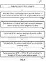
- a method implemented on a processor configured for operating a Doppler LIDAR systemincludes operating a Doppler LIDAR system to collect point cloud data that indicates for each point at least four dimensions including an inclination angle, an azimuthal angle, a range, and relative speed between the point and the LIDAR system.
- the methodalso includes determining a value of a property of an object in the point cloud based on only three or fewer of the at least four dimensions.
- determining the value of the property of the objectincludes isolating multiple points in the point cloud data which have high value Doppler components; and determining a moving object within the plurality of points based on a cluster by azimuth and Doppler component values.
- determining the value of the property of the object in the point cloudincludes identifying a plurality of stationary points in the point cloud based at least in part on an inclination angle for each point in the plurality of stationary points. This method further includes determining a ground speed of the LIDAR based on a plurality of relative speeds corresponding to the plurality of stationary points. In some of these embodiments, identifying the plurality of stationary points includes discarding from the plurality of stationary points a point with relative speed that deviates more than a threshold from a statistic based on the plurality of relative speeds corresponding to the plurality of stationary points. In some embodiments, the method includes determining an azimuthal direction of a LIDAR velocity based on an azimuthal angle associated with a stationary point for which the relative speed is a maximum among the plurality of stationary points.
- the methodincludes de-skewing by changing an azimuth or inclination or range of a point in the point cloud data based on a current LIDAR velocity and a time difference from a fixed time within a scan period.
- a method implemented on a processor configured for operating a high resolution LIDAR systemincludes operating a high resolution LIDAR system to collect point cloud data that indicates for each point at least four dimensions including an inclination angle, an azimuthal angle, a range, and a reflectivity of the point.
- the methodalso includes determining multiple objects in the point cloud. Each object is based on multiple adjacent points in the point cloud with high values of reflectivity.
- the methodincludes determining a corresponding number of objects in a database. Each object in the database has a known position.
- the methodincludes determining a position of the Doppler LIDAR system based at least in part on the known position of each object in the database for the corresponding objects in the database.
- a method implemented on a processor configured for operating a Doppler LIDAR systemincludes operating a Doppler LIDAR system to collect point cloud data that indicates for each point at least four dimensions including an inclination angle, an azimuthal angle, a range, relative speed between the point and the LIDAR system, and a reflectivity of the point.
- the methodincludes determining multiple objects in the point cloud. Each object is based on either adjacent points in the point cloud with high values of reflectivity, or adjacent points in the point cloud with relative speed values approximately appropriate for globally stationary objects.
- the methodalso includes determining a corresponding number of objects in a database. Each object in the database has a known position.
- the methodfurther includes determining a velocity of the Doppler LIDAR system based at least in part on the known position of each object in the database for the corresponding objects in the database.
- a method implemented on a processor configured for operating a Doppler LIDAR systemincludes operating a Doppler LIDAR system to collect point cloud data that indicates for each point at least four dimensions including an inclination angle, an azimuthal angle, a range, relative speed between the point and the LIDAR system, and a reflectivity of the point.
- the methodalso includes determining multiple spots on an object in the point cloud. The object is based on either adjacent points in the point cloud with high values of reflectivity, or a cluster of azimuth angle and Doppler component values.
- the methodstill further includes determining a rotation rate or global velocity of the object based on a difference in Doppler component values among the spots on the object.
- a system or apparatus or computer-readable mediumis configured to perform one or more steps of the above methods.
- FIG. 1Ais a schematic graph that illustrates the example transmitted signal as a series of binary digits along with returned optical signals for measurement of range, according to an embodiment
- FIG. 1Bis a schematic graph that illustrates an example spectrum of the reference signal and an example spectrum of a Doppler shifted return signal, according to an embodiment
- FIG. 1Cis a schematic graph that illustrates an example cross-spectrum of phase components of a Doppler shifted return signal, according to an embodiment
- FIG. 1Dis a set of graphs that illustrates an example optical chirp measurement of range, according to an embodiment
- FIG. 1Eis a graph using a symmetric LO signal, and shows the return signal in this frequency time plot as a dashed line when there is no Doppler shift, according to an embodiment
- FIG. 1Fis a graph similar to FIG. 1E , using a symmetric LO signal, and shows the return signal in this frequency time plot as a dashed line when there is a non zero Doppler shift, according to an embodiment
- FIG. 2Ais a block diagram that illustrates example components of a high resolution (hi res) Doppler LIDAR system, according to an embodiment
- FIG. 2Bis a block diagram that illustrates a saw tooth scan pattern for a hi-res Doppler system, used in some embodiments;
- FIG. 2Cis an image that illustrates an example speed point cloud produced by a hi-res Doppler LIDAR system, according to an embodiment
- FIG. 3Ais a block diagram that illustrates an example system that includes at least one hi-res Doppler LIDAR system mounted on a vehicle, according to an embodiment
- FIG. 3Bis a block diagram that illustrates an example system that includes multiple hi-res Doppler LIDAR system mounted on a vehicle, according to an embodiment
- FIG. 3Cis a block diagram that illustrates an example system that includes multiple hi-res Doppler LIDAR system mounted on a vehicle in relation to objects detected in the point cloud, according to an embodiment
- FIG. 4is a flow chart that illustrates an example method for using data from a hi res Doppler LIDAR system in an automatic vehicle setting, according to an embodiment
- FIG. 5Ais a block diagram that illustrates example components of a computation to detect own vehicle movement relative to a stationary road surface, according to an embodiment
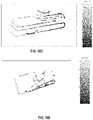
- FIG. 5Bis a plot that illustrates an example raw Doppler LIDAR point cloud, rendered in x/y/z space, not compensated for ego-motion, according to an embodiment
- FIG. 5Cis a plot that illustrates an example processed Doppler LIDAR point cloud, rendered in x/y/z space, range-compensated for ego-motion, based on Doppler-computed velocity solution, according to an embodiment
- FIG. 6is a flow diagram that illustrates an example method to determine own vehicle speed, according to an embodiment
- FIG. 7A and FIG. 7Bare graphs that illustrate an example comparison between velocities derived from global positioning system (GPS) data and hi-res 3D Doppler LIDAR data, according to an embodiment
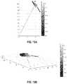
- FIG. 7C through and FIG. 7Eare graphs that illustrate example dependence of speed from Doppler LIDAR on azimuth angle relative to direction of movement of vehicle, according to an embodiment
- FIG. 7Fis a graph that illustrates example measurements of dependence of speed from Doppler LIDAR on azimuth angle, according to an embodiment.
- FIG. 8is a flow diagram that illustrates an example method to determine own vehicle velocity and other moving objects, according to another embodiment
- FIG. 9A through FIG. 9Care block diagrams that illustrate example components of a computation to detect movement of another object relative to own vehicle, according to an embodiment
- FIG. 10is a flow diagram that illustrates an example method to determine movement and track of another moving object, according to another embodiment
- FIG. 11is a block diagram that illustrates example components of a computation to determine own position relative to detected surveyed objects (stationary objects in a mapping database), according to an embodiment
- FIG. 12is a flow diagram that illustrates an example method to determine own position relative to detected surveyed objects, according to an embodiment
- FIG. 13is a block diagram that illustrates example components of a computation to determine own global velocity, according to an embodiment
- FIG. 14is a flow diagram that illustrates an example method to determine own global velocity, according to an embodiment
- FIG. 15is a block diagram that illustrates example components of a computation to determine rate of turning of a moving object relative to own vehicle, according to an embodiment
- FIG. 16is a flow diagram that illustrates an example method to determine global velocity of a moving object, according to an embodiment
- FIG. 17Ais a block diagram that illustrates example locations of illuminated spots from a hi-res Doppler LIDAR system, according to an embodiment
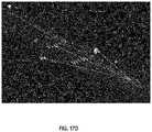
- FIG. 17B through FIG. 17Dare images that illustrate example returns from illuminated spots indicating returns from stationary objects and tracks of moving objects, according to an embodiment
- FIG. 18A through FIG. 18Care graphs that illustrate example returns from a separate vehicle as a moving object, according to an embodiment
- FIG. 18D and FIG. 18Eare plots that illustrate example measured point clouds according to an embodiment
- FIG. 19is a block diagram that illustrates a computer system upon which an embodiment of the invention may be implemented.
- FIG. 20illustrates a chip set upon which an embodiment of the invention may be implemented.
- a method and apparatus and system and computer-readable mediumare described for use of Doppler correction of optical range detection to operate a vehicle.
- numerous specific detailsare set forth in order to provide a thorough understanding of the present invention. It will be apparent, however, to one skilled in the art that the present invention may be practiced without these specific details. In other instances, well-known structures and devices are shown in block diagram form in order to avoid unnecessarily obscuring the present invention.
- a range of “less than 10” for a positive only parametercan include any and all sub-ranges between (and including) the minimum value of zero and the maximum value of 10, that is, any and all sub-ranges having a minimum value of equal to or greater than zero and a maximum value of equal to or less than 10, e.g., 1 to 4.
- Some embodiments of the inventionare described below in the context of a single front mounted hi-res Doppler LIDAR system on a personal automobile; but, embodiments are not limited to this context. In other embodiments, multiple systems with overlapping or non-overlapping fields of view or one or more such systems mounted on smaller or larger land or sea or air or space vehicles (whether autonomous or semi-autonomous or operator assisted) are employed.
- the high resolution Doppler LIDARis one, as described in inventors' earlier work, that uses a continuous wave (CW) laser with external modulation.
- CWcontinuous wave
- External modulationprovides advantages in enabling waveform flexibility through electronic control, reducing laser requirements (laser is just CW), allowing novel methods for simultaneous range and Doppler (velocity measurement), and allowing better performance at low SNR's when the beam is quickly traversing different speckle realizations.
- the shortest interval of constant phaseis a parameter of the encoding called pulse duration ⁇ and is typically the duration of several periods of the lowest frequency in the band.
- the reciprocal, 1/ ⁇ ,is baud rate, where each baud indicates a symbol.
- the number N of such constant phase pulses during the time of the transmitted signalis the number N of symbols and represents the length of the encoding.
- phase valuesIn binary encoding, there are two phase values and the phase of the shortest interval can be considered a 0 for one value and a 1 for the other, thus the symbol is one bit, and the baud rate is also called the bit rate.
- each symbolis two bits and the bit rate is twice the baud rate.
- Phase-shift keyingrefers to a digital modulation scheme that conveys data by changing (modulating) the phase of a reference signal (the carrier wave). The modulation is impressed by varying the sine and cosine inputs at a precise time.
- PSKis widely used for wireless local area networks (LANs), RF identification (RFID) and Bluetooth communication.
- LANswireless local area networks
- RFIDRFID
- Bluetooth communicationAlternatively, instead of operating with respect to a constant reference wave, the transmission can operate with respect to itself. Changes in phase of a single transmitted waveform can be considered the symbol.
- the demodulatordetermines the changes in the phase of the received signal rather than the phase (relative to a reference wave) itself.
- DPSKdifferential phase-shift keying
- the carrier frequencyis an optical frequency fc and a RF f 0 is modulated onto the optical carrier.
- the number N and duration ⁇ of symbolsare selected to achieve the desired range accuracy and resolution.
- the pattern of symbolsis selected to be distinguishable from other sources of coded signals and noise.
- a strong correlation between the transmitted and returned signalis a strong indication of a reflected or backscattered signal.
- the transmitted signalis made up of one or more blocks of symbols, where each block is sufficiently long to provide strong correlation with a reflected or backscattered return even in the presence of noise.
- the transmitted signalis made up of M blocks of N symbols per block, where M and N are non-negative integers.
- FIG. 1Ais a schematic graph 120 that illustrates the example transmitted signal as a series of binary digits along with returned optical signals for measurement of range, according to an embodiment.
- the horizontal axis 122indicates time in arbitrary units after a start time at zero.
- the vertical axis 124 aindicates amplitude of an optical transmitted signal at frequency fc+f 0 in arbitrary units relative to zero.
- the vertical axis 124 bindicates amplitude of an optical returned signal at frequency fc+f 0 in arbitrary units relative to zero, and is offset from axis 124 a to separate traces.
- Trace 125represents a transmitted signal of M*N binary symbols, with phase changes as shown in FIG.
- Trace 126represents an idealized (noiseless) return signal that is scattered from an object that is not moving (and thus the return is not Doppler shifted). The amplitude is reduced, but the code 00011010 is recognizable.
- Trace 127represents an idealized (noiseless) return signal that is scattered from an object that is moving and is therefore Doppler shifted. The return is not at the proper optical frequency fc+f 0 and is not well detected in the expected frequency band, so the amplitude is diminished.
- Equation 2c is the speed of light in the medium
- v 0is the velocity of the observer
- ⁇ ⁇ f D[ ( c + v o ) ( c + v s ) - 1 ] ⁇ f ( 2 )
- the Doppler shift erroris detected and used to process the data for the calculation of range.
- phase coded rangingthe arrival of the phase coded reflection is detected in the return by cross correlating the transmitted signal or other reference signal with the returned signal, implemented practically by cross correlating the code for a RF signal with an electrical signal from an optical detector using heterodyne detection and thus down-mixing back to the RF band.
- Cross correlation for any one lagis computed by convolving the two traces, i.e., multiplying corresponding values in the two traces and summing over all points in the trace, and then repeating for each time lag.
- the cross correlationcan be accomplished by a multiplication of the Fourier transforms of each of the two traces followed by an inverse Fourier transform.
- FFTFast Fourier transform
- the cross correlation computationis typically done with analog or digital electrical signals after the amplitude and phase of the return is detected at an optical detector.
- the optical return signalis optically mixed with the reference signal before impinging on the detector.
- a copy of the phase-encoded transmitted optical signalcan be used as the reference signal, but it is also possible, and often preferable, to use the continuous wave carrier frequency optical signal output by the laser as the reference signal and capture both the amplitude and phase of the electrical signal output by the detector.
- the return signaldoes not include the phase encoding in the proper frequency bin, the correlation stays low for all time lags, and a peak is not as readily detected, and is often undetectable in the presence of noise.
- ⁇ tis not as readily determined and range R is not as readily produced.
- FIG. 1Bis a schematic graph 140 that illustrates an example spectrum of the transmitted signal and an example spectrum of a Doppler shifted complex return signal, according to an embodiment.
- the horizontal axis 142indicates RF frequency offset from an optical carrier fc in arbitrary units.
- the vertical axis 144 aindicates amplitude of a particular narrow frequency bin, also called spectral density, in arbitrary units relative to zero.
- the vertical axis 144 bindicates spectral density in arbitrary units relative to zero, and is offset from axis 144 a to separate traces.
- Trace 145represents a transmitted signal; and, a peak occurs at the proper RF f 0 .
- Trace 146represents an idealized (noiseless) complex return signal that is backscattered from an object that is moving toward the LIDAR system and is therefore Doppler shifted to a higher frequency (called blue shifted). The return does not have a peak at the proper RF f 0 ; but, instead, is blue shifted by ⁇ f D to a shifted frequency f S .
- a complex return representing both in-phase and quadrature (I/Q) components of the returnis used to determine the peak at + ⁇ f D , thus the direction of the Doppler shift, and the direction of motion of the target on the vector between the sensor and the object, is apparent from a single return.
- FIG. 1Cis a schematic graph 150 that illustrates an example cross-spectrum, according to an embodiment.
- the horizontal axis 152indicates frequency shift in arbitrary units relative to the reference spectrum; and, the vertical axis 154 indicates amplitude of the cross spectrum in arbitrary units relative to zero.
- a peakoccurs when one of the components is blue shifted ⁇ f D1 ; and, another peak occurs when one of the components is red shifted ⁇ f D2 .
- the Doppler shiftsare determined. These shifts can be used to determine a signed velocity of approach of objects in the vicinity of the LIDAR, as can be critical for collision avoidance applications. However, if I/Q processing is not done, peaks appear at both +/ ⁇ f D1 and both +/ ⁇ f D2 , so there is ambiguity on the sign of the Doppler shift and thus the direction of movement.
- the Doppler shift(s) detected in the cross spectrumare used to correct the cross correlation so that the peak 135 is apparent in the Doppler compensated Doppler shifted return at lag ⁇ t, and range R can be determined.
- simultaneous I/Q processingis performed as described in more detail in international patent application publication entitled “Method and system for Doppler detection and Doppler correction of optical phase-encoded range detection” by S. Crouch et al., WO2018/144853.
- serial I/Q processingis used to determine the sign of the Doppler return as described in more detail in patent application publication entitled “Method and System for Time Separated Quadrature Detection of Doppler Effects in Optical Range Measurements” by S. Crouch et al., WO20019/014177.
- other meansare used to determine the Doppler correction; and, in various embodiments, any method or apparatus or system known in the art to perform Doppler correction is used.
- FIG. 1Dis a set of graphs that illustrates an example optical chirp measurement of range, according to an embodiment.
- Graph 100indicates the power of a beam of light used as a transmitted optical signal.
- the vertical axis 104 in graph 100indicates power of the transmitted signal in arbitrary units.
- Trace 106indicates that the power is on for a limited pulse duration, ⁇ starting at time 0.
- Graph 110indicates the frequency of the transmitted signal.
- the vertical axis 114indicates the frequency transmitted in arbitrary units.
- the frequency rate of changeis (f 2 ⁇ f 1 )/ ⁇ .
- the returned signalis depicted in graph 160 which has a horizontal axis 102 that indicates time and a vertical axis 114 that indicates frequency as in graph 110 .
- the chirp 116 of graph 110is also plotted as a dotted line on graph 160 .
- a first returned signalis given by trace 166 a , which is just the transmitted reference signal diminished in intensity (not shown) and delayed by ⁇ t.
- the returned signalis received from an external object after covering a distance of 2R, where R is the range to the target, the returned signal start at the delayed time ⁇ t is given by 2R/c, where c is the speed of light in the medium (approximately 3 ⁇ 10 8 meters per second, m/s), related according to Equation 3, described above.
- Equation 4bThe value of f R is measured by the frequency difference between the transmitted signal 116 and returned signal 166 a in a time domain mixing operation referred to as de-chirping. So the range R is given by Equation 4b.
- Rf R c ⁇ / 2 B (4b)
- the reference signalis delayed a known or fixed amount to ensure the returned signal overlaps the reference signal.
- the fixed or known delay time of the reference signalis multiplied by the speed of light, c, to give an additional range that is added to range computed from Equation 4b. While the absolute range may be off due to uncertainty of the speed of light in the medium, this is a near-constant error and the relative ranges based on the frequency difference are still very precise.
- a spot illuminated by the transmitted light beamencounters two or more different scatterers at different ranges, such as a front and a back of a semitransparent object, or the closer and farther portions of an object at varying distances from the LIDAR, or two separate objects within the illuminated spot.
- a second diminished intensity and differently delayed signalwill also be received, indicated on graph 160 by trace 166 b . This will have a different measured value of f R that gives a different range using Equation 4b.
- multiple additional returned signalsare received.
- Graph 170depicts the difference frequency f R between a first returned signal 166 a and the reference chirp 116 .
- the horizontal axis 102indicates time as in all the other aligned graphs in FIG. 1D , and the vertical axis 164 indicates frequency difference on a much expanded scale.
- Trace 176depicts the constant frequency f R measured in response to the transmitted chirp, which indicates a particular range as given by Equation 4b.
- the second returned signal 166 bif present, would give rise to a different, larger value of f R (not shown) during de-chirping; and, as a consequence yield a larger range using Equation 4b.
- a common method for de-chirpingis to direct both the reference optical signal and the returned optical signal to the same optical detector.
- the electrical output of the detectoris dominated by a beat frequency that is equal to, or otherwise depends on, the difference in the frequencies of the two signals converging on the detector.
- a Fourier transform of this electrical output signalwill yield a peak at the beat frequency.
- Such signalsare readily processed by common and inexpensive RF components, such as a Fast Fourier Transform (FFT) algorithm running on a microprocessor or a specially built FFT or other digital signal processing (DSP) integrated circuit.
- FFTFast Fourier Transform
- DSPdigital signal processing
- the return signalis mixed with a continuous wave (CW) tone acting as the local oscillator (versus a chirp as the local oscillator).
- CWcontinuous wave
- the detected signalwhich itself is a chirp (or whatever waveform was transmitted).
- the detected signalwould undergo matched filtering in the digital domain as described in Kachelmyer 1990.
- the disadvantageis that the digitizer bandwidth requirement is generally higher. The positive aspects of coherent detection are otherwise retained.
- the LIDAR systemis changed to produce simultaneous up and down chirps.
- This approacheliminates variability introduced by object speed differences, or LIDAR position changes relative to the object which actually does change the range, or transient scatterers in the beam, among others, or some combination.
- the approachthen guarantees that the Doppler shifts and ranges measured on the up and down chirps are indeed identical and can be most usefully combined.
- the Doppler schemeguarantees parallel capture of asymmetrically shifted return pairs in frequency space for a high probability of correct compensation.
- FIG. 1Eis a graph using a symmetric LO signal, and shows the return signal in this frequency time plot as a dashed line when there is no Doppler shift, according to an embodiment.
- the horizontal axisindicates time in example units of 10 ⁇ 5 seconds (tens of microseconds).
- the vertical axisindicates frequency of the optical transmitted signal relative to the carrier frequency f c or reference signal in example units of GigaHertz (10 9 Hertz).
- GigaHertzGigaHertz
- the two frequency bands e.g., band 1 from f 1 to f 2 , and band 2 from f 3 to f 4 )do not overlap so that both transmitted and return signals can be optically separated by a high pass or a low pass filter, or some combination, with pass bands starting at pass frequency f p .
- pass bands starting at pass frequency f pFor example f 1 ⁇ f 2 ⁇ f p ⁇ f 3 ⁇ f 4 .
- the higher frequenciesprovide the up chirp and the lower frequencies provide the down chirp, in other embodiments, the higher frequencies produce the down chirp and the lower frequencies produce the up chirp.
- two different laser sourcesare used to produce the two different optical frequencies in each beam at each time.
- a single optical carrieris modulated by a single RF chirp to produce symmetrical sidebands that serve as the simultaneous up and down chirps.
- a double sideband Mach-Zehnder intensity modulatoris used that, in general, does not leave much energy in the carrier frequency; instead, almost all of the energy goes into the sidebands.
- the bandwidth of the two optical chirpswill be the same if the same order sideband is used.
- other sidebandsare used, e.g., two second order sideband are used, or a first order sideband and a non-overlapping second sideband is used, or some other combination.
- FIG. 1Fis a graph similar to FIG. 1E , using a symmetric LO signal, and shows the return signal in this frequency time plot as a dashed line when there is a non zero Doppler shift.
- the time separated I/Q processingaka time domain multiplexing
- an AOMis used to break the range-Doppler ambiguity for real valued signals.
- scoring systemis used to pair the up and down chirp returns as described in more detail in the above cited patent application publication WO2018/160240.
- I/Q processingis used to determine the sign of the Doppler chirp as described in more detail in patent application publication entitled “Method and System for Time Separated Quadrature Detection of Doppler Effects in Optical Range Measurements” by S. Crouch et al., WO20019/014177.
- FIG. 2Ais a block diagram that illustrates example components of a high resolution Doppler LIDAR system, according to an embodiment.
- Optical signalsare indicated by arrows.
- Electronic wired or wireless connectionsare indicated by segmented lines without arrowheads.
- a laser source 212emits a carrier wave 201 that is phase or frequency modulated in modulator 282 a , before or after splitter 216 , to produce a phase coded or chirped optical signal 203 that has a duration D.
- a splitter 216splits the modulated (or, as shown, the unmodulated) optical signal for use in a reference path 220 .
- a target beam 205also called transmitted signal herein, with most of the energy of the beam 201 is produced.
- a modulated or unmodulated reference beam 207 awith a much smaller amount of energy that is nonetheless enough to produce good mixing with the returned light 291 scattered from an object (not shown) is also produced.
- the reference beam 207 ais separately modulated in modulator 282 b .
- the reference beam 207 apasses through reference path 220 and is directed to one or more detectors as reference beam 207 b .
- the reference path 220introduces a known delay sufficient for reference beam 207 b to arrive at the detector array 230 with the scattered light from an object outside the LIDAR within a spread of ranges of interest.
- the reference beam 207 bis called the local oscillator (LO) signal referring to older approaches that produced the reference beam 207 b locally from a separate oscillator.
- the referenceis caused to arrive with the scattered or reflected field by: 1) putting a mirror in the scene to reflect a portion of the transmit beam back at the detector array so that path lengths are well matched; 2) using a fiber delay to closely match the path length and broadcast the reference beam with optics near the detector array, as suggested in FIG.
- the objectis close enough and the transmitted duration long enough that the returns sufficiently overlap the reference signal without a delay.
- the transmitted signalis then transmitted to illuminate an area of interest, often through some scanning optics 218 .
- the detector arrayis a single paired or unpaired detector or a 1 dimensional (1D) or 2 dimensional (2D) array of paired or unpaired detectors arranged in a plane roughly perpendicular to returned beams 291 from the object.
- the reference beam 207 b and returned beam 291are combined in zero or more optical mixers 284 to produce an optical signal of characteristics to be properly detected.
- the frequency, phase or amplitude of the interference pattern, or some combination,is recorded by acquisition system 240 for each detector at multiple times during the signal duration D.
- the number of temporal samples processed per signal durationaffects the down-range extent.
- the numberis often a practical consideration chosen based on number of symbols per signal, signal repetition rate and available camera frame rate.
- the frame rateis the sampling bandwidth, often called “digitizer frequency.”
- the only fundamental limitations of range extentare the coherence length of the laser and the length of the chirp or unique phase code before it repeats (for unambiguous ranging). This is enabled because any digital record of the returned heterodyne signal or bits could be compared or cross correlated with any portion of transmitted bits from the prior transmission history.
- the acquired datais made available to a processing system 250 , such as a computer system described below with reference to FIG. 19 , or a chip set described below with reference to FIG. 20 .
- a signed Doppler compensation module 270determines the sign and size of the Doppler shift and the corrected range based thereon along with any other corrections described herein.
- the processing system 250also provides scanning signals to drive the scanning optics 218 , and includes a modulation signal module to send one or more electrical signals that drive modulators 282 a , 282 b , as illustrated in FIG. 2 .
- the processing systemalso includes a vehicle control module 272 to provide information on the vehicle position and movement relative to a shared geospatial coordinate system or relative to one or more detected objects or some combination.
- the vehicle control module 272also controls the vehicle (not shown) in response to such information.
- any known apparatus or systemmay be used to implement the laser source 212 , modulators 282 a , 282 b , beam splitter 216 , reference path 220 , optical mixers 284 , detector array 230 , scanning optics 218 , or acquisition system 240 .
- Optical coupling to flood or focus on a target or focus past the pupil planeare not depicted.
- an optical coupleris any component that affects the propagation of light within spatial coordinates to direct light from one component to another component, such as a vacuum, air, glass, crystal, mirror, lens, optical circulator, beam splitter, phase plate, polarizer, optical fiber, optical mixer, among others, alone or in some combination.
- FIG. 2Aalso illustrates example components for a simultaneous up and down chirp LIDAR system according to one embodiment.
- the modulator 282 ais a frequency shifter added to the optical path of the transmitted beam 205 .
- the frequency shifteris added instead to the optical path of the returned beam 291 or to the reference path 220 .
- the frequency shifting elementis added as modulator 282 b on the local oscillator (LO, also called the reference path) side or on the transmit side (before the optical amplifier) as the device used as the modulator (e.g., an acousto-optic modulator, AOM) has some loss associated and it is disadvantageous to put lossy components on the receive side or after the optical amplifier.
- LOlocal oscillator
- AOMacousto-optic modulator
- the purpose of the optical shifteris to shift the frequency of the transmitted signal (or return signal) relative to the frequency of the reference signal by a known amount ⁇ fs, so that the beat frequencies of the up and down chirps occur in different frequency bands, which can be picked up, e.g., by the FFT component in processing system 250 , in the analysis of the electrical signal output by the optical detector 230 .
- the blue shift causing range effectsis f B
- the beat frequency of the up chirpwill be increased by the offset and occur at f B + ⁇ fs and the beat frequency of the down chirp will be decreased by the offset to f B ⁇ fs.
- the up chirpswill be in a higher frequency band than the down chirps, thereby separating them. If ⁇ fs is greater than any expected Doppler effect, there will be no ambiguity in the ranges associated with up chirps and down chirps.
- the measured beatscan then be corrected with the correctly signed value of the known ⁇ fs to get the proper up-chirp and down-chirp ranges.
- the RF signal coming out of the balanced detectoris digitized directly with the bands being separated via FFT.
- the RF signal coming out of the balanced detectoris pre-processed with analog RF electronics to separate a low-band (corresponding to one of the up chirp or down chip) which can be directly digitized and a high-band (corresponding to the opposite chirp) which can be electronically down-mixed to baseband and then digitized. Both embodiments offer pathways that match the bands of the detected signals to available digitizer resources.
- FIG. 2Bis a block diagram that illustrates a saw tooth scan pattern for a hi-res Doppler LIDAR system, used in some embodiments.
- the scansweeps through a range of azimuth angles (horizontally) and inclination angles (vertically above and below a level direction at zero inclination). In other embodiments, other scan patters are used. Any scan pattern known in the art may be used in various embodiments.
- adaptive scanningis performed using methods described in international patent application publications by Crouch entitled “Method and system for adaptive scanning with optical ranging systems,” WO2018/125438, or entitled “Method and system for automatic real-time adaptive scanning with optical ranging systems,” WO2018/102188.
- FIG. 2Cis an image that illustrates an example speed point cloud produced by a scanning hi-res Doppler LIDAR system, according to an embodiment.
- a point cloudeach element of the cloud represents the return from a spot.
- the spot sizeis a function of the beam width and the range.
- Each pixel of the 2D imageindicates a different spot illuminated by a particular azimuth angle and inclination angle, and each spot has associated a range (third dimension) and speed (4 th dimension) relative to the LIDAR.
- a reflectivity measureis also indicated by the intensity or amplitude of the returned signal (a fifth dimension).
- each point of the point cloudrepresents at least a 4D vector and possibly a 5D vector.
- a scanning hi-res range-Doppler LIDARproduces a high-resolution 3D point cloud image with point by point signed relative speed of the scene in view of the LIDAR system.
- a Doppler relative speedis determined with high granularity ( ⁇ 0.25 m/s) across a very large speed spread (>+/ ⁇ 100 m/s).
- the use of coherent measurement techniquestranslates an inherent sensitivity to Doppler into a simultaneous range-Doppler measurement for the LIDAR scanner. Additionally, the coherent measurement techniques allow a very high dynamic range measurement relative to more traditional LIDAR solutions. The combination of these data fields allows for powerful vehicle location in the presence of INS dropouts.
- a vehicleis controlled at least in part based on data received from a hi-res Doppler LIDAR system mounted on the vehicle.
- FIG. 3Ais a block diagram that illustrates an example system that includes at least one hi-res Doppler LIDAR system 320 mounted on a vehicle 310 , according to an embodiment.
- the vehiclehas a center of mass indicted by a star 311 and travels in a forward direction given by arrow 313 .
- the vehicle 310includes a component, such as a steering or braking system (not shown), operated in response to a signal from a processor.
- the vehiclehas an on-board processor 314 , such as chip set depicted in FIG. 20 .
- the on board processor 314is in wired or wireless communication with a remote processor, as depicted in FIG. 19 .
- the hi-res Doppler LIDARuses a scanning beam 322 that sweeps from one side to another side, represented by future beam 323 , through an azimuthal field of view 324 , as well as through vertical angles (not shown) illuminating spots in the surroundings of vehicle 310 .
- the field of viewis 360 degrees of azimuth.
- the inclination angle field of viewis from about +10 degrees to about ⁇ 10 degrees or a subset thereof.
- the vehicleincludes ancillary sensors (not shown), such as a GPS sensor, odometer, tachometer, temperature sensor, vacuum sensor, electrical voltage or current sensors, among others well known in the art.
- ancillary sensorssuch as a GPS sensor, odometer, tachometer, temperature sensor, vacuum sensor, electrical voltage or current sensors, among others well known in the art.
- a gyroscope 330is included to provide rotation information.
- FIG. 3AAlso depicted in FIG. 3A is a global coordinate system represented by an arrow pointing north and an arrow pointing east from a known geographic location represented by a point at the base of both arrows.
- Data in a mapping systemas a geographical information system (GIS) database is positioned relative to the global positioning system.
- GISgeographical information system
- FIG. 3Bis a block diagram that illustrates an example system that includes multiple hi-res Doppler LIDAR systems mounted on a vehicle 310 , according to an embodiment. Items 310 , 311 , 313 and 314 , and the global coordinate system, are as depicted in FIG. 3A .
- the multiple hi-res Doppler LIDAR systems, 340 a , 340 b , 340 c , 340 care positioned on the vehicle 310 to provide complete angular coverage, with overlap at some angles, at least for ranges beyond a certain distance.
- FIG. 3Bis a block diagram that illustrates an example system that includes multiple hi-res Doppler LIDAR systems mounted on a vehicle 310 , according to an embodiment. Items 310 , 311 , 313 and 314 , and the global coordinate system, are as depicted in FIG. 3A .
- 3Balso depicts the fields of view 344 a , 344 b , 344 c , 344 d , respectively (hereinafter collectively referenced as fields of view 344 ) between instantaneous leftmost beams 342 a , 342 b , 342 c , 342 d , respectively (hereinafter collectively referenced as leftmost beams 342 ) and rightmost beams 343 a , 343 b , 343 c , 343 d , respectively (hereinafter collectively referenced as rightmost beams 343 ).
- more or fewer hi-res Doppler LIDAR systems 340are used with smaller or larger fields of view 344 .
- FIG. 3Cis a block diagram that illustrates an example system that includes multiple hi-res Doppler LIDAR systems 340 mounted on a vehicle 310 in relation to objects detected in the point cloud, according to an embodiment.
- Items 310 , 311 , 313 , 314 , 340 , 342 , 343 and 344 , as well as the global coordinate system,are as depicted in FIG. 3B .
- Items detectable in a 3D point cloud from the systems 340includes road surface 391 , curbs 395 , stop sign 392 , light posts 393 a , 393 b , 393 c (collectively referenced hereinafter as light posts 393 ), lane markings 394 and moving separate vehicle 396 .
- the separate moving vehicle 396is turning and so has a different velocity vector 397 a at a front of the vehicle from a velocity vector 397 b at the rear of the vehicle.
- Some of these items, such as stop sign 392 and light posts 393might have global coordinates in a GIS database.
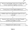
- FIG. 4is a flow chart that illustrates an example method 400 for using data from a high resolution Doppler LIDAR system in an automatic or assisted vehicle setting, according to an embodiment.
- stepsare depicted in FIG. 4 , and in subsequent flowcharts in FIG. 6 , FIG. 8 , FIG. 10 , FIG. 12 , FIG. 14 and FIG. 16 , as integral steps in a particular order for purposes of illustration, in other embodiments, one or more steps, or portions thereof, are performed in a different order, or overlapping in time, in series or in parallel, or are omitted, or one or more additional steps are added, or the method is changed in some combination of ways.
- a high-resolution Doppler LIDAR system 340is configured on a vehicle 310 (also called an own vehicle below to distinguish form separate vehicles 396 in the vicinity).
- the configurationincludes installing the LIDAR system 340 on the vehicle 310 .
- Configuration datais stored in one or more own vehicle databases, either locally on vehicle 310 or remotely or some combination.
- Configuration dataincludes at least the position of the system 340 relative to a center of mass 311 of the vehicle and a field of view 344 of the system relative to the forward direction 313 of the vehicle.
- step 40includes storing other constants or parameter values of methods used in one or more of the following steps, such as a value for a solution tolerance for the own vehicle's velocity as described below with reference to FIG. 8 .
- step 403sensors systems on own vehicle are operated.
- an inertial navigation systemINS
- GPSGlobal Positioning System
- 3D point cloud datafrom the hi-res Doppler LIDAR system to calibrate the position and direction of the field of view of the LIDAR relative to the center of mass and direction of the vehicle.
- the calibration datais stored in the one or more databases.
- the hi-res Doppler LIDARis operated to construct a scene comprising a 3D point cloud with relative speed at each point as a result of one complete scan at each of one or more such LIDAR systems 340 .
- the scene datais analyzed to determine stationary objects (e.g., roadbed 391 or traffic sign 392 or lamp posts 393 or curb 395 or markings 394 or some combination), own speed relative to stationary objects (also called ego-motion herein), and speed and direction of one or more moving objects (e.g., 396), if any.
- stationary objectse.g., roadbed 391 or traffic sign 392 or lamp posts 393 or curb 395 or markings 394 or some combination
- own speed relative to stationary objectsalso called ego-motion herein
- speed and direction of one or more moving objectse.g., 396
- a maxThe maximum component-wise change of the vehicle velocity vector (a max ) is advantageously small compared to the product of the scan period (T scan ) and the Doppler resolution (m) of the LIDAR, as given by Equation 4.
- a max ⁇ T scan r D(4)
- each spot of the point cloudmeasured in less than a millisecond so that point clouds of hundreds of spots can be accumulated in less than a tenth of a second.
- the hi-res Doppler phase-encoded LIDAR described abovecan achieve a 500 Mbps to 1 Gbps baud rate.
- the range windowcan be made to extend to several kilometers under these conditions and that the Doppler resolution can also be quite high (depending on the duration of the transmitted signal).
- step 421it is determined if the moving objects represent a danger to the own vehicle, e.g., where own vehicle velocity or moving object velocity or some combination indicates a collision or near collision. If so, then, in step 423 , danger mitigation action is caused to be initiated, e.g., by sending an alarm to an operator or sending a command signal that causes one or more systems on the own vehicle, such as brakes or steering or airbags, to operate. In some embodiments, the danger mitigation action includes determining what object is predicted to be involved in the collision or near collision.
- the objectis identified based on reflectivity variations or shape or some combination using any methods known in the art. For example, in some embodiments, object identification is performed using methods described in PCT patent application by Crouch entitled “method and system for classification of an object in a point cloud data set,” WO2018/102190. In some embodiments, the object is identified based on global position of own vehicle and a GIS indicating a global position for the other stationary or moving object.
- Controlpasses back to step 405 , to collect the next scene using the hi-res Doppler LIDAR system 340 .
- the loop of steps 405 to 411 to 421 to 423is repeated until there is no danger determined in step 421 . Obviously, the faster a scan can be measured, the faster the loop can be completed.
- step 431it is determined if the speed of the own vehicle is reliable (indicated by: OK′′ in FIG. 4 ).
- the calibration dataindicates the odometer is working properly and signals are being received from the odometer, or the gyroscope indicates the own vehicle is not spinning.
- speed determined from the 3D point cloud with relative speedis used to determine speed in the global coordinate system and the speed is not OK if the odometer disagrees with the speed determined from the point cloud. If not, then in step 433 speed is determined based on the 3D point cloud with relative speed data. In some embodiments, such speed relative to the road surface or other ground surface is determined automatically in step 411 .
- step 433that previously used speed relative to the ground surface is used in step 433 .
- 3D point cloud dataare selected for such speed determination and the speed determination is made instead, or again, during step 433 . Control then passes to step 441 .
- step 441it is determined if the speed and direction of the own vehicle indicate danger, such as danger of leaving the roadway or of exceeding a safe range of speeds for the vehicle or road conditions, if, for example, values for such parameters are in the one or more own vehicle databases. If so, control passes to step 443 to initiate a danger mitigation action. For example, in various embodiments, initiation of danger mitigation action includes sending an alarm to an operator or sending a command signal that causes one or more systems on the own vehicle, such as brakes or steering, to operate to slow the vehicle to a safe speed and direction, or airbags to deploy. Control then passes back to step 405 to collect the hi-res Doppler LIDAR data to construct the next scene.
- step 451it is determined if the relative location of the own vehicle is reliable (indicated by: OK′′ in FIG. 4 ). For example, distance to high reflectivity spots, such as a curb or lane markings, are consistent with being on a road going in the correct direction. If not, then in step 453 relative location is determined based on the 3D point cloud with relative speed data based on measured distances to high reflectivity spots, such as road markings and curbs. In some embodiments, such relative location of own vehicle is determined automatically in step 411 . In some embodiments, that previously used relative location of own vehicle is used in step 453 . In some embodiments, 3D point cloud data of stationary highly reflective objects are selected to determine relative location of own vehicle during step 453 . Control then passes to step 461 .
- step 461it is determined if the relative location of the own vehicle indicates danger, such as danger of leaving the roadway. If so, control passes to step 463 to initiate a danger mitigation action. For example, in various embodiments, initiation of danger mitigation action includes sending an alarm to an operator or sending a command signal that causes one or more systems on the own vehicle, such as brakes or steering, to operate to direct the own vehicle to remain on the roadway, or airbags to deploy. Control then passes back to step 405 to collect the hi-res Doppler LIDAR data to construct the next scene.
- initiation of danger mitigation actionincludes sending an alarm to an operator or sending a command signal that causes one or more systems on the own vehicle, such as brakes or steering, to operate to direct the own vehicle to remain on the roadway, or airbags to deploy.
- step 470global location is determined based on the 3D point cloud with relative speed data. In some embodiments, such global location of own vehicle is determined automatically in step 411 . In some embodiments, that previously used global location of own vehicle is used again in step 470 . In some embodiments, 3D point cloud data of stationary objects, such as road signs and lamp posts, or moving objects with precisely known global coordinates and trajectories, such as orbiting objects, are selected and cross referenced with the GIS to determine global location of own vehicle during step 470 . In some embodiments, step 470 is omitted. Control then passes to step 481 .
- step 481it is determined if the global location of the own vehicle indicates danger, such as danger of being on the wrong roadway to progress to a particular destination. If so, control passes to step 483 to initiate a danger mitigation action. For example, in various embodiments, initiation of danger mitigation action includes sending an alarm to an operator or sending a command signal that causes one or more systems on the own vehicle, such as brakes or steering, to operate to direct the own vehicle to the correct global location, or airbags to deploy. Control then passes back to step 405 to collect the hi-res Doppler LIDAR data to construct the next scene.
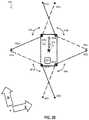
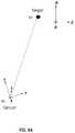
- FIG. 5Ais a block diagram that illustrates example components of a computation to detect own vehicle movement relative to a stationary road surface (ego-motion), according to an embodiment.
- the relative speeds V r1 and V r2are measured directly by the hi-res Doppler LIDAR system as observed in the reference frame of the sensor 520 . These speeds are equal to the dot product of the inverse unit vectors l 1 ′ and l 2 ′, respectively, and the velocity V of the vehicle, as given in Equation 5a and 5b.
- V r1l 1 ′ ⁇ V (5a)
- V r2l 2 ′ ⁇ V (5b) Since l 1 ′ and l 2 ′ are known and V r1 and V r2 , are measured, and V is known to be horizontal (parallel to road surface 590 ) and assumed to be in the direction of the vehicle heading, each equation can be solved for V. However, due to systematic errors, each determination can be in error. To remove systematic errors, a difference is determined as given by equation 5c and the difference equation is solved for V.
- V r1 ⁇ V r2( l 1 ′ ⁇ l 2 ′) ⁇ V (5c) Or expressed differently as equation 5d.
- the LIDAR systemis operated to collect point cloud data that indicates for each point an inclination angle and relative speed between the point and the LIDAR system. Multiple stationary points are identified in the point cloud based on an inclination angle for each point. Then the determining ground speed of the LIDAR (and by inference the ground speed of the vehicle) is based on multiple relative speeds corresponding to the multiple stationary points.
- this processingis limited to two dimensions (inclination and Doppler component) of the 4 or 5 dimensions (inclination, azimuth, range and Doppler component) available in the data.
- Thisis an example of determining a value of a property of an object in the point cloud based on only three or fewer of the at least four dimensions.
- An advantage of this two-dimensional approachis that various computational methods for solving simultaneous equations with noise are much more efficient than they would be if those methods had to be executed in three or four dimensions.
- FIG. 5Bis a plot that illustrates an example raw Doppler LIDAR point cloud, rendered in x/y/z space, not compensated for ego-motion, according to an embodiment.
- FIG. 5Cis a plot that illustrates an example processed Doppler LIDAR point cloud, rendered in x/y/z space, range-compensated for ego-motion, based on Doppler-computed velocity solution, according to an embodiment.
- FIG. 6is a flow diagram that illustrates an example method to determine own vehicle speed, according to an embodiment. This embodiment is based on Equations 5a through 5d.
- step 601hi-res Doppler LIDAR data is acquired, corresponding to step 405 in FIG. 4 .
- spots in the dataare identified that correspond to the stationary ground surface and in front of the vehicle.
- the ground pointsare identified based on a manual input, e.g., a graphical user interface (GUI) that allows a user to enclose spots in the 3D data cloud to use as ground surface spots. This can also be done automatically based on geometric features, e.g., using points along a line in front of the vehicle along a direction 313 of the vehicle heading and at negative inclination angles.
- GUIgraphical user interface
- step 605the unit vectors l between the sensor and multiple spots on the ground surface are determined.
- step 607⁇ l′ is determined for random pairs of spots on the ground surface.
- step 609⁇ Vr is determined based on the measured Doppler speeds for the random pair of spots.
- step 611Equation 5d is solved for the random pair to obtain V.
- steps 607 , 609 and 611are repeated for multiple random pairs and averaged to further reduce the effects of noise in the measurements.
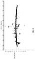
- FIG. 7A and FIG. 7Bare graphs that illustrate an example comparison between velocities derived from global positioning system (GPS) data and hi-res Doppler LIDAR data, according to an embodiment.
- FIG. 7Adepicts graph 710 with a horizontal axis indicating time in arbitrary units of scan number, and vertical axis indicating speed in forward direction 313 in units of meters per second from a low of about 1 to a high of about 15.
- Trace 716shows speed derived from GPS and is called the GPS solution. Vehicle slows to almost a stop at point 716 a and reaches a high speed at point 716 b .
- Box 718indicates a section replotted at expanded scale in graph 720 of FIG. 7B .
- Graph 720has a horizontal axis indicating time in arbitrary units of scan number, and has a vertical axis indicating speed in forward direction 313 in units of meters per second from a low of about 11.1 to a high of about 12.
- Trace 726shows the GPS solution and trace 727 shows the speed derived from the point cloud from the hi-res Doppler LIDAR, called the Doppler solution. There is close agreement, within about 0.1 meters per second. Both have systematic errors that contribute to the very small drift noticed in these two traces.
- Equation 5dis itself subject to random noise in the measurements V r1 and V r2 and that it was difficult to determine objectively which spots represented the stationary ground surface rather than a moving object. It was recognized that measured speeds in direction other than the direction 313 of the vehicle could be used to reduce the effects of noise in the determination of own vehicle velocity (speed and direction). Further, using other azimuthal directions can avoid making the assumption that the vehicle is moving in the forward direction.
- FIG. 7C through and FIG. 7Eare graphs that illustrate example dependence of speed from Doppler LIDAR on azimuth angle relative to direction of movement of vehicle, according to an embodiment. Plot 730 in FIG. 7C depicts measured Doppler speeds in one experiment scanning across 360 degrees.
- the horizontal axisindicates azimuth angle from ⁇ 180 degrees to 180 degrees.
- the vertical axisindicates Doppler speed in meters per second from ⁇ 2.5 to +2.5.
- Open circlesindicate measurements of the ground (i.e., the assumed stationary points). At each azimuth several speeds are measured as the LIDAR scans the 360 degrees several times. The range in speeds during the experiment are due to noise in the measurement. There were no moving objects in this experiment to contaminate the measurement of stationary points in the point cloud.
- Azimuths in frontshow positive speeds as the relative motion is toward the vehicle, with a maximum in the direction of movement near an azimuth of 0 degrees relative to the direction of the 313 of the vehicle 310 .
- Difference form zeroindicates a velocity different from the assumed forward direction of the vehicle.
- Rearward azimuth anglesshow a negative speed as the ground spots relative emotion is away from the vehicle.
- the datacan be fit with a polynomial given by trace 737 that resembles a cosine function.
- azimuthal direction of the ground speedis determined based on an azimuthal angle associated with a stationary point of the plurality of stationary points for which the relative velocity is a maximum among the plurality of stationary points.
- the true ground speedis based on the plurality of stationary points for which the relative velocity is a maximum.
- Plot 740 in FIG. 7Dhas a horizontal axis that indicates azimuth angle from ⁇ 30 degrees to 30 degrees.
- the vertical axisindicates Doppler speed in meters per second from 0 to +2.5.
- the dots 746represent the measurements from about ⁇ 25 degrees azimuth to about 25 degrees; and the trace 747 the polynomial fit.
- plot 750 in FIG. 7Ehas a horizontal axis that indicates azimuth angle from ⁇ 60 degrees to 60 degrees.
- the vertical axisindicates Doppler speed in meters per second from 0 to +2.5.
- the dots 756represent the measurements from about ⁇ 25 degrees azimuth to about 25 degrees; and the trace 757 the polynomial fit.
- the azimuth corrected vehicle velocityis represented by the polynomial trace in FIG. 7C through FIG. 7D .
- FIG. 7Fis a graph that illustrates example measurements of dependence of speed from Doppler LIDAR on azimuth angle, according to an embodiment.
- This projectionshows a Doppler LIDAR point cloud rendered in Azimuth/Range/Doppler space, but then rotated to show the azimuth and Doppler axes only. Distinct moving objects are obvious when viewed from this perspective, as is the cosine structure of the stationary spots.
- Equation 5a through 5dWe generalize the two-dimensional treatment of Equations 5a through 5d, to three dimensions with x, y and z representing east, north and up, respectively.
- a computationally efficient but potentially numerically unstable approachis to form a system of three equations with three unknowns from three instances of Equation 6 for a set of points detected by the scanner within a short time interval.
- Ais a matrix of the inverse unit vectors l′ for each Doppler measurement, each vector l′ having three components l x ′ l y ′ l z ′ for the x, y and z directions
- Vis the 3 dimensional vector of vehicle velocity
- Dis an array of the scalar measured Doppler relative speeds.
- This approachis sensitive to the choice of points used to form the system, as inverting A will fail if the matrix A is approximately singular. This would occur if the points have very similar beam vectors, e.g., they were collected over a small angular area. Additionally, due to noise in the measurement of the Doppler value as well as the range, an exact solution is unlikely, and the solution must be iteratively converged to.
- This formulationis highly sensitive to spots on a moving object being included in a solution, so a simple, low-level method for avoiding inclusion of spots on moving objects is advantageous.
- moving objectsmay be segmented out by applying a filter based on their compatibility with the most recent previous velocity solution.
- Equation 9For a normalized beam vector of the nth sample, the detected Doppler of a stationary object should follow the relationship given by Equation 9. l′ n ⁇ ( V+ ⁇ V )> V rn >l′ n ⁇ ( V ⁇ V ) (9)
- ⁇ Vis a small vector describing the amount of error expected in the Doppler velocity measurement of the scanner multiplied by the maximum expected change in vehicle velocity since the previous solution was sampled. This can be estimated by the most recent acceleration and the sampling time (scan or sub-scan period), among other approaches.
- Equation 7takes the form of Equation 10a
- Equation 10a[ V r ⁇ ⁇ 1 ... V r ⁇ ⁇ 3 ] ( 10 ⁇ a )
- R[ l x ⁇ ⁇ 1 ′ l y ⁇ ⁇ 1 ′ l z ⁇ ⁇ 1 ′ ... ... ... l xn ′ l yn ′ l zn ′ ] ⁇ [ V x V y V z ] - [ V r ⁇ ⁇ 1 ... V r ⁇ ⁇ 3 ] ( 10 ⁇ b )
- Rrepresents the differences between the data points and the azimuth corrected vehicle velocity represented by the polynomial trace in FIG. 7C through FIG. 7D .
- a non-counter-scanning patternis a scanning pattern of one or more LIDAR beams in which all beams always travel in the same direction at all times in the execution of a single scanning frame.
- a counter-scanning patternis a scanning pattern in which one or more lidar beams travel in more than one opposite direction, either concurrently or at different points in its execution of a single scanning frame.
- the FOV limitcan be approximated for moderate angles ( ⁇ ⁇ 80 degrees) as given by Equation 10c: r ⁇ v ⁇ (1 ⁇ cos ⁇ ) (10c)
- ⁇is the velocity resolution of the Doppler LIDAR sensor
- ⁇ v ⁇is the magnitude of the vehicle velocity vector
- ⁇is the smaller of the two angles between the direction of travel and one of the edges of the FOV.
- FIG. 8is a flow diagram that illustrates an example method to determine own vehicle velocity and other moving objects, according to another embodiment.
- This embodimentis based on the residual column vector R given in Equation 10b and not only determines own motion (ego-motion), but also compensates for the detection of moving and stationary objects based on ego-motion.
- ego-motionis actually the motion of the LIDAR system; and that motion is imputed to the motion of the vehicle to which the LIDAR is fixed.
- the ego-motions for multiple LIDAR systems on the same vehiclecan be combined to determine the vehicle's motion.
- a current velocity vector Vcurrentis determined. Any method may be used to determine the current velocity vector which is essentially a first guess for the solution to be found using the method 800 .
- the current velocity vectoris zero.
- the current velocity vectormay be selected as the last speed from the odometer in the direction the vehicle was traveling at the time.
- the current velocity vectoris chosen to be equal the solution at the previous time increment.
- the current velocityis determined using the downward inclination pairs and the azimuth with the maximum speed, as described above.
- Step 801includes determining a solution tolerance, a first threshold for residuals associated with stationary spots in the 3D point cloud, an angle bin size for objects expected to move at the same speed, and a residual bin size for similarly moving objects.
- the first thresholdis a velocity difference that is greater than a change in vehicle velocity over a scan time. For example if a scan is completed in 1 millisecond, and a vehicle can accelerate 100 kilometers per hour in ten seconds (about 3 meters per second per second) then a change of more than 0.003 meters per second is not expected to be due to a change in own vehicle speed, and the change is probably due to a moving object being scanned. In such a case the first threshold is about 0.01 meters per second per second.
- any methodmay be used to determine the values, including retrieving from local or remote memory or storage, computing using a standard algorithm, receiving in a message from a remote process, either unsolicited or in response to a request for information.
- values for all these parametersare determined during step 401 in FIG. 4 and stored in the one or more databases, such a with configuration data.
- step 803the 3D point cloud data collected during a single scan is corrected for skew due to the current velocity. Skew arises when the vehicle moves during the time the LIDAR scans a scene. So ranges and Doppler speeds associated with each point in the point cloud can be corrected to the beginning of the scan time, or a time midway through the scan, or to a time at the end of the scan, or any other time, using the current value for the vehicle velocity.
- step 803includes changing an azimuth or inclination or range of a point in the point cloud data based on a current LIDAR velocity and a time difference from a fixed time within a scan period. In some embodiments, skew is not important or is ignored, and step 803 is omitted.
- a residual vectoris determined based on the current vehicle velocity, e.g., R is computed using Equation 10b with V x , V y and V z based on the current value for the vehicle velocity Vcurrent.
- the rows of the residual vectorare then a measure of how much a speed of a point in the point cloud data differs from the current vehicle velocity. If the difference is too great, the point is probably not on a stationary object, such as the ground surface, but, instead, is on a moving object.
- the next stepsare an attempt to discover such spots on moving objects and remove those points from the computation of own vehicle velocity.
- step 811a next row in the residual vector R is selected.
- step 813it is determined whether the residual value on that row is greater than the first threshold for stationary spots. If so, then the row is probably not for a Doppler observation of a stationary object and control passes to step 815 .
- step 817the removed row is added to a different residual vector for each of one or more moving objects based on the angle bin size and residual bin size.
- Each moving object residual vectorincludes only residuals in a certain residual range spanning no more than one residual bin size and only angles in a certain angle range spanning no more than one angle bin size.
- Controlthen passes to step 811 to select the next row for the residual vector R.
- the removed rowsare not added to moving object residual vectors and step 817 is omitted; and, control passes from step 815 to step 811 .
- step 813If it is determined in step 813 that the next row does not have a residual greater than the first threshold, then control passes to step 821 .
- step 821it is determined if there are any more rows of the residual vector R left to select. If so, then control passes back to step 811 to select the next row. If not, then control passes to step 823 .
- step 823operations, such as SVD operations, are performed to determine values of Vcurrent that minimize R to a new set of values Rnew.
- the solutionis obtained by iteratively searching for a pseudo inverse of the n ⁇ 3 matrix A in Equation 10a using the singular value decomposition, a factorization of an arbitrary matrix given by Equation 11a.
- AU ⁇ V* (11a) where U is a unitary matrix of size n ⁇ n; ⁇ is a diagonal matrix of size n ⁇ 3, V is a 3 ⁇ 3 unitary matrix, and V* is the conjugate transpose of V.
- the pseudo inverse of A, A ⁇ 1is based on the approximation given by Equation 11b.
- step 825it is determined whether the new residuals have been sufficiently reduced. This is done by seeing if the size ⁇ R ⁇ of the new residual vector Rnew is less than or equal to a target velocity tolerance. Any method may be used to determine the size ⁇ R ⁇ , such as the maximum element of Rnew, the sum of the elements of Rnew, the sum of the absolute values of the elements of Rnew, the sum of the squares of the elements of Rnew, among others.
- the value of the tolerancedepends on how the size of Rnew is determined. For example, the residual tolerance should scale along with the error of the Doppler measurement (the error in beam direction also contributes, but is small by comparison).
- the normalized L2 norm of the residual of a perfect solutionshould simply be the variance of the Doppler measurement, or the standard deviation squared if the error is Gaussian. A good tolerance would be some small multiple of the variance. If the tolerance is smaller than this, it is unlikely to be met and the end condition will not be achieved. If Rnew is greater than the tolerance, then control passes to step 827 .
- step 827the first threshold value is decreased, so as to remove more rows from the new residual vector Rnew.
- the processis restarted by making Rnew the current residual vector; and making the first row of the residual vector the next row to be selected.
- Controlpasses to step 811 to select the next row of the residual vector.
- a loopis formed to repeat the process until a velocity vector Vcurrent is determined with residual vector size at or below the tolerance desired.
- a limitis placed on the number of iterations, e.g., the process stops after 100 iterations or when the difference in velocity V between successive iterations is less than a certain percentage, such as 1%.
- step 831a rotation determined based on data form a gyroscope, if any, is added tot the velocity vector V. Purely rotational motion (spinning about a fixed axis) however cannot be detected by equations described above, so a sensor capable of directly detecting rotational velocity, such as a vibrating structure gyroscope, is recommended as an additional input on any vehicle that is capable of dominantly rotational motion. In some embodiments, a gyroscope is not included and step 831 is omitted. Control then passes to step 833 .
- step 833it is determined whether skew is to be corrected.
- Computing the vehicle velocity solution based on a set of detected points over a time intervalallows a self-consistent way to correct for “rolling shutter”-like skew effects caused by the finite scan speed of the LIDAR's beam within that time interval. For example, a flat upright surface perpendicular to the velocity vector of a LIDAR system with a horizontally scanning beam will appear to be skewed diagonally, as points detected later within the interval will possess shorter ranges due to vehicle translation towards the surface.
- a velocity vector extracted from the set of detected pointscan be used to provide an instantaneous, self-consistent measurement of the translation of the vehicle during the collection time interval, and the set de-skewed by back-projecting each point along this vector by an amount given by dt* ⁇ v ⁇ . If this is to be done, then control passes back to step 803 to de-skew the data. If not, control passes to step 841 .
- step 841the equations formed by moving rows removed from the stationary data points are used to solve for the velocity V of the moving objects in the 3D point cloud relative to the own vehicle using the above method on each moving object residual vector.
- the velocity of own vehicleis added to this velocity to get the global coordinate velocity Vg of these one or more moving objects, if any.
- adjacent objectsare determined to be moving similarly, then it is possible to merge the adjacent objects into one object by merging the rows for the two moving object residual vectors and associated Doppler speeds, and then solving for V for the merged equations. Control then passes to step 843 .
- FIG. 9A through FIG. 9Care block diagrams that illustrate example components of a computation to detect movement of another object relative to own vehicle, according to an embodiment.
- sensor 921 of a hi-res Doppler LIDAR systemis mounted on a vehicle proceeding with velocity in the vehicle forward direction y.
- the sensoris at a height above a road surface; and, during a scan short compared to a time for the vehicle to move an appreciable distance, receives returns from spot 991 in response to scanning beams at an azimuth angle represented by unit vector l.
- the global coordinate systemis indicated by the vectors N in the north direction and E in the east direction, respectively, from a global origin represented by the 3D point A.
- the returnsimply gives the position of the spot 991 .
- the object represented by spot 991is moving with velocity indicated by vector V.
- the relative speeds V ris given by the dot product of the inverse unit vector, l′ and the velocity V, e.g., given by Equation 12.
- V rl′ ⁇ V (12) and is measured directly by the hi-res Doppler LIDAR system as observed in the reference frame of the sensor 921 .
- both the target object 991 and the sensor 921are moving at velocities Vtarget and Vsensor, respectively.
- Vr_corrThe relative speed (Vr_corr) of the target measured by the hi-res Doppler LIDAR at the sensor is the sum of the two speeds along the line connecting them given by Equation 13.
- FIG. 10is a flow diagram that illustrates an example method 1000 to determine movement and track of another moving object, according to another embodiment. This embodiment is based on Equations 12 and 13.
- a point cloud based on hi-res Doppler LIDAR datais filtered to isolate points with large values of Doppler speeds.
- the pointsare clustered based on similar Doppler speed values. Each cluster of similar Doppler speeds in similar azimuthal directions, e.g., a small range of azimuthal angles compared to 360 degrees, is considered an object.
- step 1005a list of objects of high Doppler clusters for each time step is maintained.
- step 1007object clusters at different times are associated on the basis of spatial (azimuthal and inclination) proximity and Doppler similarity.
- step 1009an object track for the associated object clusters are determined and maintained, e.g., in computer storage.
- this processingis limited to three dimensions (inclination, azimuth and Doppler component) of the 4 or 5 dimensions (inclination, azimuth, range, Doppler component, and reflectivity) available in the data.
- Thisis another example of determining a value of a property of an object in the point cloud based on only three or fewer of the at least four dimensions.
- An advantage of this three-dimensional approachis that various computational methods for clustering and solving simultaneous equations with noise are more efficient than they would be if those methods had to be executed in four dimensions. Thus, solutions can be determined in less time, for any processing power available, and therefore this approach provides more time to respond to any dangerous situations.
- FIG. 11is a block diagram that illustrates example components of a computation to determine own position relative to detected surveyed objects (e.g., stationary objects in a mapping database or moving objects of known positions with time), according to an embodiment.
- surveyed objectse.g., stationary objects in a mapping database or moving objects of known positions with time
- Sensor 1121 of a hi-res Doppler LIDAR systemis mounted on a vehicle at position given by 3D vector p; and, during a scan short compared to a time for the vehicle to move an appreciable distance, receives returns from spots 1191 and 1192 at different ranges represented by 3D vectors r 1 and r 2 , respectively, and azimuthal angles in response to scanning beams at azimuth angles represented by unit vectors l 1 and l 2 , respectively.
- the known locations of the two objectsare given by 3D vectors t 1 and t 2 respectively.
- the datasatisfy the following set of Equations 14a through 14e.
- FIG. 12is a flow diagram that illustrates an example method 1200 to determine own position relative to detected surveyed objects, according to an embodiment.
- hi-res LIDAR imageryis obtained. It need not be Doppler imagery.
- high reflectivity objects in sceneare identified. These are likely to include objects of known positions, such as street signs 392 , lampposts 393 , etc.
- cross reference location of objects with surveyed objects in vicinitye.g., from a geographic information system (GIS) database. If own position is not well known, these cross references are approximate. e.g., a surveyed object in the GIS might be the detected object or might not.
- GISgeographic information system
- step 1207a set of line of sight unit vectors l between sensor and detected objects are determined.
- step 1209⁇ l is calculated for random pairings of such detected objects.
- step 1211solve for R using Equation 14d with measured ⁇ l and ⁇ t from surveyed position of objects, e.g., from GIS.
- step 1213R, l and t for multiple pairings are each use to estimate position p of sensor.
- a geometric average of the multiple values for pis determined to get an estimated value for p.
- a confidence level for the value pis also determined during step 213 .
- FIG. 13is a block diagram that illustrates example components of a computation to determine own global velocity, according to an embodiment.
- the sensoris on a moving vehicle at position p with velocity V.
- Sensor 1321 of a hi-res Doppler LIDAR systemis mounted on a vehicle at position given by 3D vector p; and, during a scan short compared to a time for the vehicle to move an appreciable distance, receives returns from non-moving spots 1391 and 1392 at different azimuthal angles in response to scanning beams at azimuth angles represented by unit vectors l 1 and l 2 , respectively.
- the datasatisfy the following set of Equations 14a through 14e.
- Vl′V (15a)
- V 1 ⁇ V 2l′ 1 V ⁇ l′ 2
- V( l′ 1 ⁇ l′ 2 ) V
- ⁇ l′V⁇ V (15c)
- V globalRV local (15d)
- FIG. 14is a flow diagram that illustrates an example method 1400 to determine own global velocity, according to an embodiment.
- step 1401hi-res Doppler LIDAR imagery is obtained.
- step 1403identify points in scene with Doppler values consistent with globally static surfaces, using one or more of the techniques described above.
- step 1405a set of line of sight unit vectors Z between sensor and detected stationary objects are determined.
- step 1407⁇ l is calculated for such detected spots.
- step 1409solve for Vlocal using Equation 15c with measured ⁇ l′ and ⁇ .
- Ris used to estimate Vglobal.
- FIG. 15is a block diagram that illustrates example components of a computation to determine rate of turning of a moving object relative to own vehicle, according to an embodiment.
- Sensor 1521 of a hi-res Doppler LIDAR systemis mounted on a vehicle; and, during a scan short compared to a time for the vehicle to move an appreciable distance, receives returns from spots 1591 and 1592 at different locations on a turning object moving with velocity V.
- the spotsare at azimuthal angles detected in response to scanning beams at azimuth angles represented by unit vectors l 1 and l 2 , respectively.
- the detected Doppler speedsare V r1 and V r2 , respectively.
- the datasatisfy the following set of Equations 16a through 16d.
- V r1l′ 1 V (16a)
- ⁇ l′V⁇ V (16d)
- FIG. 16is a flow diagram that illustrates an example method 1600 to determine global velocity of a moving object, according to an embodiment.
- step 1601hi-res Doppler LIDAR imagery is obtained.
- step 1603own vehicle motion is corrected for using Equation 13 to obtain Vr_corr for each spot detected.
- step 1605several spots on the same moving object are clustered based on Doppler speed and azimuthal angle proximity.
- step 1607a set of line of sight unit vectors l between sensor and detected spots on moving object are determined.
- ⁇ lis calculated for random pairings of such detected spots.
- step 1611⁇ Vr_corr is calculated for random pairings of such detected spots.
- step 1613solve for V using Equation 16d with measured ⁇ l′ and ⁇ V.
- This Vis used as Vglobal for the detected object.
- a linear velocityis the subject of the equations in FIG. 15 and the method in FIG. 16 .
- rotating objectsmay violate that equality ⁇ ; and some measure of rotation rate would be advantageous.
- FIG. 17Ais a block diagram that illustrates example locations of illuminated spots from a hi-res Doppler LIDAR system, according to an embodiment. These scanned spots are on the road surface and used to determine own global velocity according to method 600 or method 800 .
- FIG. 17B through FIG. 17Dare images that illustrate example returns from illuminated spots indicating returns from stationary objects and tracks of moving objects, according to an embodiment. These images are used to track objects using method 800 or 1000 .
- FIG. 18A through FIG. 18Care graphs that illustrate example returns from a separate vehicle as a moving object, according to an embodiment. Doppler points are clustered by speed and azimuthal and inclination angle proximity. The net movement of the object is determined using the method 1600 .
- FIG. 18D and FIG. 18Eare plots that illustrate example measured point clouds according to an embodiment. Each point is shaded according to the measured velocity. A pickup truck turning a corner is depicted, so this object is undergoing translational and rotational motion simultaneously. This is a real-data manifestation of the simulated data depicted in FIG. 8A and FIG. 8B .
- FIG. 19is a block diagram that illustrates a computer system 1900 upon which an embodiment of the invention may be implemented.
- Computer system 1900includes a communication mechanism such as a bus 1910 for passing information between other internal and external components of the computer system 1900 .
- Informationis represented as physical signals of a measurable phenomenon, typically electric voltages, but including, in other embodiments, such phenomena as magnetic, electromagnetic, pressure, chemical, molecular atomic and quantum interactions. For example, north and south magnetic fields, or a zero and non-zero electric voltage, represent two states (0, 1) of a binary digit (bit). Other phenomena can represent digits of a higher base.
- a superposition of multiple simultaneous quantum states before measurementrepresents a quantum bit (qubit).
- a sequence of one or more digitsconstitutes digital data that is used to represent a number or code for a character.
- information called analog datais represented by a near continuum of measurable values within a particular range.
- Computer system 1900or a portion thereof, constitutes a means for performing one or more steps of one or more methods described herein.
- a sequence of binary digitsconstitutes digital data that is used to represent a number or code for a character.
- a bus 1910includes many parallel conductors of information so that information is transferred quickly among devices coupled to the bus 1910 .
- One or more processors 1902 for processing informationare coupled with the bus 1910 .
- a processor 1902performs a set of operations on information.
- the set of operationsinclude bringing information in from the bus 1910 and placing information on the bus 1910 .
- the set of operationsalso typically include comparing two or more units of information, shifting positions of units of information, and combining two or more units of information, such as by addition or multiplication.
- a sequence of operations to be executed by the processor 1902constitutes computer instructions.
- Computer system 1900also includes a memory 1904 coupled to bus 1910 .
- the memory 1904such as a random access memory (RAM) or other dynamic storage device, stores information including computer instructions. Dynamic memory allows information stored therein to be changed by the computer system 1900 . RAM allows a unit of information stored at a location called a memory address to be stored and retrieved independently of information at neighboring addresses.
- the memory 1904is also used by the processor 1902 to store temporary values during execution of computer instructions.
- the computer system 1900also includes a read only memory (ROM) 1906 or other static storage device coupled to the bus 1910 for storing static information, including instructions, that is not changed by the computer system 1900 .
- ROMread only memory
- Also coupled to bus 1910is a non-volatile (persistent) storage device 1908 , such as a magnetic disk or optical disk, for storing information, including instructions, that persists even when the computer system 1900 is turned off or otherwise loses power.
- Informationis provided to the bus 1910 for use by the processor from an external input device 1912 , such as a keyboard containing alphanumeric keys operated by a human user, or a sensor.
- an external input device 1912such as a keyboard containing alphanumeric keys operated by a human user, or a sensor.
- a sensordetects conditions in its vicinity and transforms those detections into signals compatible with the signals used to represent information in computer system 1900 .
- Other external devices coupled to bus 1910used primarily for interacting with humans, include a display device 1914 , such as a cathode ray tube (CRT) or a liquid crystal display (LCD), for presenting images, and a pointing device 1916 , such as a mouse or a trackball or cursor direction keys, for controlling a position of a small cursor image presented on the display 1914 and issuing commands associated with graphical elements presented on the display 1914 .
- a display device 1914such as a cathode ray tube (CRT) or a liquid crystal display (LCD)
- LCDliquid crystal display
- pointing device 1916such as a mouse or a trackball or cursor direction keys
- special purpose hardwaresuch as an application specific integrated circuit (IC) 1920
- the special purpose hardwareis configured to perform operations not performed by processor 1902 quickly enough for special purposes.
- application specific ICsinclude graphics accelerator cards for generating images for display 1914 , cryptographic boards for encrypting and decrypting messages sent over a network, speech recognition, and interfaces to special external devices, such as robotic arms and medical scanning equipment that repeatedly perform some complex sequence of operations that are more efficiently implemented in hardware.
- Computer system 1900also includes one or more instances of a communications interface 1970 coupled to bus 1910 .
- Communication interface 1970provides a two-way communication coupling to a variety of external devices that operate with their own processors, such as printers, scanners and external disks. In general the coupling is with a network link 1978 that is connected to a local network 1980 to which a variety of external devices with their own processors are connected.
- communication interface 1970may be a parallel port or a serial port or a universal serial bus (USB) port on a personal computer.
- communications interface 1970is an integrated services digital network (ISDN) card or a digital subscriber line (DSL) card or a telephone modem that provides an information communication connection to a corresponding type of telephone line.
- ISDNintegrated services digital network
- DSLdigital subscriber line
- a communication interface 1970is a cable modem that converts signals on bus 1910 into signals for a communication connection over a coaxial cable or into optical signals for a communication connection over a fiber optic cable.
- communications interface 1970may be a local area network (LAN) card to provide a data communication connection to a compatible LAN, such as Ethernet.
- LANlocal area network
- Wireless linksmay also be implemented.
- Carrier waves, such as acoustic waves and electromagnetic waves, including radio, optical and infrared wavestravel through space without wires or cables. Signals include man-made variations in amplitude, frequency, phase, polarization or other physical properties of carrier waves.
- the communications interface 1970sends and receives electrical, acoustic or electromagnetic signals, including infrared and optical signals, that carry information streams, such as digital data.
- Non-volatile mediainclude, for example, optical or magnetic disks, such as storage device 1908 .
- Volatile mediainclude, for example, dynamic memory 1904 .
- Transmission mediainclude, for example, coaxial cables, copper wire, fiber optic cables, and waves that travel through space without wires or cables, such as acoustic waves and electromagnetic waves, including radio, optical and infrared waves.
- the term computer-readable storage mediumis used herein to refer to any medium that participates in providing information to processor 1902 , except for transmission media.
- Computer-readable mediainclude, for example, a floppy disk, a flexible disk, a hard disk, a magnetic tape, or any other magnetic medium, a compact disk ROM (CD-ROM), a digital video disk (DVD) or any other optical medium, punch cards, paper tape, or any other physical medium with patterns of holes, a RAM, a programmable ROM (PROM), an erasable PROM (EPROM), a FLASH-EPROM, or any other memory chip or cartridge, a carrier wave, or any other medium from which a computer can read.
- the term non-transitory computer-readable storage mediumis used herein to refer to any medium that participates in providing information to processor 1902 , except for carrier waves and other signals.
- Logic encoded in one or more tangible mediaincludes one or both of processor instructions on a computer-readable storage media and special purpose hardware, such as ASIC 1920 .
- Network link 1978typically provides information communication through one or more networks to other devices that use or process the information.
- network link 1978may provide a connection through local network 1980 to a host computer 1982 or to equipment 1984 operated by an Internet Service Provider (ISP).
- ISP equipment 1984in turn provides data communication services through the public, world-wide packet-switching communication network of networks now commonly referred to as the Internet 1990 .
- a computer called a server 1992 connected to the Internetprovides a service in response to information received over the Internet.
- server 1992provides information representing video data for presentation at display 1914 .
- the inventionis related to the use of computer system 1900 for implementing the techniques described herein. According to one embodiment of the invention, those techniques are performed by computer system 1900 in response to processor 1902 executing one or more sequences of one or more instructions contained in memory 1904 . Such instructions, also called software and program code, may be read into memory 1904 from another computer-readable medium such as storage device 1908 . Execution of the sequences of instructions contained in memory 1904 causes processor 1902 to perform the method steps described herein.
- hardwaresuch as application specific integrated circuit 1920 , may be used in place of or in combination with software to implement the invention. Thus, embodiments of the invention are not limited to any specific combination of hardware and software.
- the signals transmitted over network link 1978 and other networks through communications interface 1970carry information to and from computer system 1900 .
- Computer system 1900can send and receive information, including program code, through the networks 1980 , 1990 among others, through network link 1978 and communications interface 1970 .
- a server 1992transmits program code for a particular application, requested by a message sent from computer 1900 , through Internet 1990 , ISP equipment 1984 , local network 1980 and communications interface 1970 .
- the received codemay be executed by processor 1902 as it is received, or may be stored in storage device 1908 or other non-volatile storage for later execution, or both. In this manner, computer system 1900 may obtain application program code in the form of a signal on a carrier wave.
- instructions and datamay initially be carried on a magnetic disk of a remote computer such as host 1982 .
- the remote computerloads the instructions and data into its dynamic memory and sends the instructions and data over a telephone line using a modem.
- a modem local to the computer system 1900receives the instructions and data on a telephone line and uses an infra-red transmitter to convert the instructions and data to a signal on an infra-red a carrier wave serving as the network link 1978 .
- An infrared detector serving as communications interface 1970receives the instructions and data carried in the infrared signal and places information representing the instructions and data onto bus 1910 .
- Bus 1910carries the information to memory 1904 from which processor 1902 retrieves and executes the instructions using some of the data sent with the instructions.
- the instructions and data received in memory 1904may optionally be stored on storage device 1908 , either before or after execution by the processor 1902 .
- FIG. 20illustrates a chip set 2000 upon which an embodiment of the invention may be implemented.
- Chip set 2000is programmed to perform one or more steps of a method described herein and includes, for instance, the processor and memory components described with respect to FIG. 19 incorporated in one or more physical packages (e.g., chips).
- a physical packageincludes an arrangement of one or more materials, components, and/or wires on a structural assembly (e.g., a baseboard) to provide one or more characteristics such as physical strength, conservation of size, and/or limitation of electrical interaction.
- the chip setcan be implemented in a single chip.
- Chip set 2000or a portion thereof, constitutes a means for performing one or more steps of a method described herein.
- the chip set 2000includes a communication mechanism such as a bus 2001 for passing information among the components of the chip set 2000 .
- a processor 2003has connectivity to the bus 2001 to execute instructions and process information stored in, for example, a memory 2005 .
- the processor 2003may include one or more processing cores with each core configured to perform independently.
- a multi-core processorenables multiprocessing within a single physical package. Examples of a multi-core processor include two, four, eight, or greater numbers of processing cores.
- the processor 2003may include one or more microprocessors configured in tandem via the bus 2001 to enable independent execution of instructions, pipelining, and multithreading.
- the processor 2003may also be accompanied with one or more specialized components to perform certain processing functions and tasks such as one or more digital signal processors (DSP) 2007 , or one or more application-specific integrated circuits (ASIC) 2009 .
- DSP 2007typically is configured to process real-world signals (e.g., sound) in real time independently of the processor 2003 .
- ASIC 2009can be configured to performed specialized functions not easily performed by a general purposed processor.
- Other specialized components to aid in performing the inventive functions described hereininclude one or more field programmable gate arrays (FPGA) (not shown), one or more controllers (not shown), or one or more other special-purpose computer chips.
- FPGAfield programmable gate arrays
- the processor 2003 and accompanying componentshave connectivity to the memory 2005 via the bus 2001 .
- the memory 2005includes both dynamic memory (e.g., RAM, magnetic disk, writable optical disk, etc.) and static memory (e.g., ROM, CD-ROM, etc.) for storing executable instructions that when executed perform one or more steps of a method described herein.
- the memory 2005also stores the data associated with or generated by the execution of one or more steps of the methods described herein.
- indefinite article “a” or “an”is meant to indicate one or more of the item, element or step modified by the article.
- a valueis “about” another value if it is within a factor of two (twice or half) of the other value. While example ranges are given, unless otherwise clear from the context, any contained ranges are also intended in various embodiments. Thus, a range from 0 to 10 includes the range 1 to 4 in some embodiments.
Landscapes
- Physics & Mathematics (AREA)
- Engineering & Computer Science (AREA)
- Electromagnetism (AREA)
- Radar, Positioning & Navigation (AREA)
- Remote Sensing (AREA)
- General Physics & Mathematics (AREA)
- Computer Networks & Wireless Communication (AREA)
- Automation & Control Theory (AREA)
- Mathematical Physics (AREA)
- Transportation (AREA)
- Mechanical Engineering (AREA)
- Optical Radar Systems And Details Thereof (AREA)
- Optics & Photonics (AREA)
- Aviation & Aerospace Engineering (AREA)
- Traffic Control Systems (AREA)
- Control Of Position, Course, Altitude, Or Attitude Of Moving Bodies (AREA)
Abstract
Description
Note that the magnitude of the error increases with the frequency f of the signal. Note also that for a stationary LIDAR system (v0=0), for an object moving at 10 meters a second (vs=10), and visible light of frequency about 500 THz, then the size of the error is on the order of 16 megahertz (MHz, 1 MHz=106hertz, Hz, 1 Hz=1 cycle per second). In various embodiments described below, the Doppler shift error is detected and used to process the data for the calculation of range.
R=c*Δt/2 (3)
fR=(f2−f1)/τ*2R/c=2BR/cτ (4a)
R=fRcτ/2B (4b)
Of course, if the returned signal arrives after the pulse is completely transmitted, that is, if 2R/c is greater than τ, then Equations 4a and 4b are not valid. In this case, the reference signal is delayed a known or fixed amount to ensure the returned signal overlaps the reference signal. The fixed or known delay time of the reference signal is multiplied by the speed of light, c, to give an additional range that is added to range computed from Equation 4b. While the absolute range may be off due to uncertainty of the speed of light in the medium, this is a near-constant error and the relative ranges based on the frequency difference are still very precise.
amax<TscanrD (4)
For example, a LIDAR sensor with rD=0.25 m/s and a 10 Hz scan rate (Tscan=0.1 sec) may fail to properly segment moving actors if the vehicle's acceleration exceeds 2.5 m/s2. As this is not a particularly high value, current implementations solve for velocity on each “Framelet” (left-to-right scan of a vertical array of one or more concurrent Doppler LIDAR beams), rather than a full vertical frame (which consists of one or more framelets conducted sequentially in time at differing inclination angle offsets). This allows typical operation of the velocity solution to have an effective 80 Hz scan rate, giving a maximum acceleration of 20 m/s2—more than two times the acceleration of gravity, sufficient for many vehicle scenarios, including most automobile operations. Similar limits exist for velocity estimation of other objects, because, to first order, the variation in velocity across the extent of the other object advantageously exceeds the characteristic Doppler noise value for a determination of the motion of the other object.
Vr1=l1′·V (5a)
Vr2=l2′·V (5b)
Since l1′ and l2′ are known and Vr1and Vr2, are measured, and V is known to be horizontal (parallel to road surface590) and assumed to be in the direction of the vehicle heading, each equation can be solved for V. However, due to systematic errors, each determination can be in error. To remove systematic errors, a difference is determined as given by equation 5c and the difference equation is solved for V.
Vr1−Vr2=(l1′−l2′)·V (5c)
Or expressed differently as equation 5d.
ΔVr=Δl′·V (5d)
Where ΔVr=Vr1−Vr2and Δl′=l1′−l2′, as shown in
Vr=l′·V (6)
ΔV=D (7)
Where A is a matrix of the inverse unit vectors l′ for each Doppler measurement, each vector l′ having three components lx′ ly′ lz′ for the x, y and z directions, V is the 3 dimensional vector of vehicle velocity and D is an array of the scalar measured Doppler relative speeds. Explicitly:
l′n·(V+ΔV)>Vrn>l′n·(V−ΔV) (9)
Here ΔV is a small vector describing the amount of error expected in the Doppler velocity measurement of the scanner multiplied by the maximum expected change in vehicle velocity since the previous solution was sampled. This can be estimated by the most recent acceleration and the sampling time (scan or sub-scan period), among other approaches.
A solution is found for the overdetermined expression given by Equation 10a, where the goal is to find the vector V that minimizes a residual vector R that is a column vector of size (n×1) given by Equation 10b.
Essentially, R represents the differences between the data points and the azimuth corrected vehicle velocity represented by the polynomial trace in
r<∥v∥(1−cos θ) (10c)
Where τ is the velocity resolution of the Doppler LIDAR sensor, ∥v∥ is the magnitude of the vehicle velocity vector and θ is the smaller of the two angles between the direction of travel and one of the edges of the FOV.
A=UΣV* (11a)
where U is a unitary matrix of size n×n; Σ is a diagonal matrix of size n×3, V is a 3×3 unitary matrix, and V* is the conjugate transpose of V. The pseudo inverse of A, A−1, is based on the approximation given by Equation 11b.
A−1≈VΣ−1U* (11b)
Because Σ is a diagonal matrix it is easy to invert; and U* is just the conjugate transpose of U. In this case, the residual R is used only to compute the “quality” of the pseudo inverse solution.
Vr=l′·V (12)
and is measured directly by the hi-res Doppler LIDAR system as observed in the reference frame of the
Vr_corr=l′·Vtarget+l·Vsensor=l′·Vtarget−l′·Vsensor (13)
r1−r2=t1−t2 (14a)
r=rRl (14b)
R(r1l1−r2l2)=t1−t2 (14c)
RΔl=Δt (14d)
p=rRl+t (14e)
Thus the 3D vector for the sensor position, p, is determined.
V=l′V (15a)
V1−V2=l′1V−l′2V=(l′1−l′2)V (15b)
Δl′V=ΔV (15c)
Vglobal=RVlocal (15d)
Thus the 3D vector for the sensor velocity, Vglobal, is determined.
Vr1=l′1V (16a)
Vr2−l′2V (16b)
Vr1−Vr2=l′1V−l′2V=(l′1−l′2)V (16c)
Δl′V=ΔV (16d)
Thus the global velocity of the target is obtained from the relative velocity of the two spots on the moving target.
Claims (20)
Priority Applications (3)
| Application Number | Priority Date | Filing Date | Title |
|---|---|---|---|
| US17/167,857US11500106B2 (en) | 2018-04-23 | 2021-02-04 | LIDAR system for autonomous vehicle |
| US17/956,389US11947017B2 (en) | 2018-04-23 | 2022-09-29 | Lidar system for autonomous vehicle |
| US18/587,208US20240192379A1 (en) | 2018-04-23 | 2024-02-26 | Lidar system for autonomous vehicle |
Applications Claiming Priority (4)
| Application Number | Priority Date | Filing Date | Title |
|---|---|---|---|
| US201862661327P | 2018-04-23 | 2018-04-23 | |
| PCT/US2019/028532WO2019209727A1 (en) | 2018-04-23 | 2019-04-22 | Method and system for controlling autonomous vehicle using coherent range doppler optical sensors |
| US16/725,399US10914841B2 (en) | 2018-04-23 | 2019-12-23 | LIDAR system for autonomous vehicle |
| US17/167,857US11500106B2 (en) | 2018-04-23 | 2021-02-04 | LIDAR system for autonomous vehicle |
Related Parent Applications (1)
| Application Number | Title | Priority Date | Filing Date |
|---|---|---|---|
| US16/725,399ContinuationUS10914841B2 (en) | 2018-04-23 | 2019-12-23 | LIDAR system for autonomous vehicle |
Related Child Applications (1)
| Application Number | Title | Priority Date | Filing Date |
|---|---|---|---|
| US17/956,389ContinuationUS11947017B2 (en) | 2018-04-23 | 2022-09-29 | Lidar system for autonomous vehicle |
Publications (2)
| Publication Number | Publication Date |
|---|---|
| US20210278544A1 US20210278544A1 (en) | 2021-09-09 |
| US11500106B2true US11500106B2 (en) | 2022-11-15 |
Family
ID=68295757
Family Applications (4)
| Application Number | Title | Priority Date | Filing Date |
|---|---|---|---|
| US16/725,399ActiveUS10914841B2 (en) | 2018-04-23 | 2019-12-23 | LIDAR system for autonomous vehicle |
| US17/167,857ActiveUS11500106B2 (en) | 2018-04-23 | 2021-02-04 | LIDAR system for autonomous vehicle |
| US17/956,389ActiveUS11947017B2 (en) | 2018-04-23 | 2022-09-29 | Lidar system for autonomous vehicle |
| US18/587,208PendingUS20240192379A1 (en) | 2018-04-23 | 2024-02-26 | Lidar system for autonomous vehicle |
Family Applications Before (1)
| Application Number | Title | Priority Date | Filing Date |
|---|---|---|---|
| US16/725,399ActiveUS10914841B2 (en) | 2018-04-23 | 2019-12-23 | LIDAR system for autonomous vehicle |
Family Applications After (2)
| Application Number | Title | Priority Date | Filing Date |
|---|---|---|---|
| US17/956,389ActiveUS11947017B2 (en) | 2018-04-23 | 2022-09-29 | Lidar system for autonomous vehicle |
| US18/587,208PendingUS20240192379A1 (en) | 2018-04-23 | 2024-02-26 | Lidar system for autonomous vehicle |
Country Status (6)
| Country | Link |
|---|---|
| US (4) | US10914841B2 (en) |
| EP (2) | EP3785043B1 (en) |
| JP (4) | JP2021515241A (en) |
| KR (3) | KR102272212B1 (en) |
| CN (2) | CN115079195A (en) |
| WO (1) | WO2019209727A1 (en) |
Cited By (1)
| Publication number | Priority date | Publication date | Assignee | Title |
|---|---|---|---|---|
| US20230176203A1 (en)* | 2021-12-06 | 2023-06-08 | Microsoft Technology Licensing, Llc | Radar Tracking With Greater Than Range Resolution Precision |
Families Citing this family (50)
| Publication number | Priority date | Publication date | Assignee | Title |
|---|---|---|---|---|
| US12399278B1 (en) | 2016-02-15 | 2025-08-26 | Red Creamery Llc | Hybrid LIDAR with optically enhanced scanned laser |
| US12399279B1 (en) | 2016-02-15 | 2025-08-26 | Red Creamery Llc | Enhanced hybrid LIDAR with high-speed scanning |
| US12123950B2 (en) | 2016-02-15 | 2024-10-22 | Red Creamery, LLC | Hybrid LADAR with co-planar scanning and imaging field-of-view |
| US11556000B1 (en) | 2019-08-22 | 2023-01-17 | Red Creamery Llc | Distally-actuated scanning mirror |
| KR102380216B1 (en) | 2016-11-29 | 2022-03-28 | 블랙모어 센서스 앤드 애널리틱스, 엘엘씨 | Method and system for classification of an object in a point cloud data set |
| EP3548841A4 (en) | 2016-11-30 | 2020-06-10 | Blackmore Sensors And Analytics Inc. | Method and system for doppler detection and doppler correction of optical chirped range detection |
| US10422880B2 (en) | 2017-02-03 | 2019-09-24 | Blackmore Sensors and Analytics Inc. | Method and system for doppler detection and doppler correction of optical phase-encoded range detection |
| US10816666B2 (en)* | 2017-11-21 | 2020-10-27 | Magna Electronics Inc. | Vehicle sensing system with calibration/fusion of point cloud partitions |
| CN109840448A (en)* | 2017-11-24 | 2019-06-04 | 百度在线网络技术(北京)有限公司 | Information output method and device for automatic driving vehicle |
| CN115079195A (en)* | 2018-04-23 | 2022-09-20 | 布莱克莫尔传感器和分析有限责任公司 | Method and system for controlling autonomous vehicle with coherent range-doppler optical sensor |
| US10921817B1 (en)* | 2018-06-29 | 2021-02-16 | Zoox, Inc. | Point cloud filtering with semantic segmentation |
| US10955857B2 (en)* | 2018-10-02 | 2021-03-23 | Ford Global Technologies, Llc | Stationary camera localization |
| CN111174777A (en) | 2018-11-09 | 2020-05-19 | 阿里巴巴集团控股有限公司 | Positioning method and device and electronic equipment |
| US20200209391A1 (en)* | 2018-12-26 | 2020-07-02 | Industrial Technology Research Institute | Automatic vehicular sensor adjustment method and system thereof |
| US11041944B2 (en)* | 2019-03-01 | 2021-06-22 | Beijing Voyager Technology Co., Ltd. | Constant false alarm rate detection in pulsed LiDAR systems |
| US11828848B2 (en)* | 2019-03-14 | 2023-11-28 | Aeva, Inc. | Velocity estimation using doppler per point LiDAR systems |
| JP7143800B2 (en)* | 2019-03-22 | 2022-09-29 | 株式会社デンソー | lidar device |
| US11619724B2 (en)* | 2019-06-26 | 2023-04-04 | Nvidia Corporation | Calibration of multiple lidars mounted on a vehicle using localization based on a high definition map |
| US10838061B1 (en)* | 2019-07-16 | 2020-11-17 | Blackmore Sensors & Analytics, LLC. | Method and system for enhanced velocity resolution and signal to noise ratio in optical phase-encoded range detection |
| US11821990B2 (en)* | 2019-11-07 | 2023-11-21 | Nio Technology (Anhui) Co., Ltd. | Scene perception using coherent doppler LiDAR |
| US11726189B2 (en)* | 2019-12-09 | 2023-08-15 | Nio Technology (Anhui) Co., Ltd. | Real-time online calibration of coherent doppler lidar systems on vehicles |
| US11892560B2 (en) | 2020-02-03 | 2024-02-06 | Nio Technology (Anhui) Co., Ltd | High precision multi-sensor extrinsic calibration via production line and mobile station |
| US11209529B2 (en)* | 2020-03-05 | 2021-12-28 | Aurora Operations, Inc. | Coherent signal combining with multiple-outputs for quasi-CW LIDAR operation |
| US20230154099A1 (en)* | 2020-03-31 | 2023-05-18 | Pioneer Corporation | Information processing device, computer program, recording medium, and display data creation method |
| GB202004950D0 (en)* | 2020-04-03 | 2020-05-20 | Secr Defence | Computer implemented method for detecting pulsed radiation |
| CN111611900B (en)* | 2020-05-15 | 2023-06-30 | 北京京东乾石科技有限公司 | Target point cloud identification method and device, electronic equipment and storage medium |
| CN111665522B (en)* | 2020-05-19 | 2022-12-16 | 上海有个机器人有限公司 | Method, medium, terminal and device for filtering static object in laser scanning pattern |
| DE102020206771A1 (en) | 2020-05-29 | 2021-12-02 | Siemens Mobility GmbH | Method for estimating an airspeed |
| IL275007A (en)* | 2020-05-31 | 2021-12-01 | Qualcomm Inc | Improved clustering in automotive imaging radar |
| IT202000017329A1 (en)* | 2020-07-16 | 2022-01-16 | Ids Georadar S R L | METHOD AND APPARATUS FOR REDUCING BLURRING PHENOMENA IN IMAGES OBTAINED BY GROUND-BASED RADAR |
| US11448748B2 (en) | 2020-09-10 | 2022-09-20 | Argo AI, LLC | Systems and methods for simultaneous range-rate unwrapping and outlier removal for radar |
| US20220120905A1 (en)* | 2020-10-15 | 2022-04-21 | Waymo Llc | Speed Determination Using Light Detection and Ranging (LIDAR) Device |
| US11327158B1 (en)* | 2020-10-19 | 2022-05-10 | Aeva, Inc. | Techniques to compensate for mirror Doppler spreading in coherent LiDAR systems using matched filtering |
| US11662454B2 (en) | 2020-11-02 | 2023-05-30 | Ford Global Technologies, Llc | Systems and methods for range-rate dealiasing using position consistency |
| CN116671078A (en) | 2020-11-06 | 2023-08-29 | 大众汽车股份公司 | Access node, user equipment, apparatus, method and computer program for determining delay-doppler resolution for a transceiver of a mobile communication system |
| US11841420B2 (en) | 2020-11-16 | 2023-12-12 | Oculii Corp. | System and method for radar-based localization and/or mapping |
| US20220187458A1 (en)* | 2020-12-14 | 2022-06-16 | Waymo Llc | Lidar devices with frequency and time multiplexing of sensing signals |
| KR20220092116A (en)* | 2020-12-24 | 2022-07-01 | 현대자동차주식회사 | Method and apparatus for tracking object, and recording medium for recording program performing the method |
| EP4024077A1 (en)* | 2021-01-04 | 2022-07-06 | Aptiv Technologies Limited | Methods and system for compressing radar data |
| EP4036601A1 (en)* | 2021-01-29 | 2022-08-03 | Aptiv Technologies Limited | Radar data processing for vehicle ego-motion estimation |
| EP4337989A4 (en)* | 2021-05-11 | 2025-03-05 | Opsys Tech Ltd. | Pixel mapping solid-state lidar transmitter system and method |
| KR102655213B1 (en)* | 2021-07-08 | 2024-04-05 | 한국과학기술원 | Noise filtering method for point cloud of 4 dimensional radar and data processing apparatus |
| CN117813529A (en)* | 2021-08-26 | 2024-04-02 | 松下知识产权经营株式会社 | Sensor device, processing device and method for processing data |
| US12174311B2 (en)* | 2021-09-03 | 2024-12-24 | Texas Instruments Incorporated | Empty band doppler division multiple access |
| CN113822914A (en)* | 2021-09-13 | 2021-12-21 | 中国电建集团中南勘测设计研究院有限公司 | Method for unifying oblique photography measurement model, computer device, product and medium |
| CN113970552B (en)* | 2021-09-26 | 2024-06-14 | 北京京仪仪器仪表研究总院有限公司 | Apple nondestructive testing method combining laser speckle and Kmeans clustering algorithm |
| CN117999499A (en)* | 2021-10-13 | 2024-05-07 | 松下知识产权经营株式会社 | Data processing apparatus and data processing method |
| CN114154535A (en)* | 2021-11-18 | 2022-03-08 | 中汽创智科技有限公司 | Object recognition method, device, device and storage medium |
| EP4414742A1 (en)* | 2023-02-08 | 2024-08-14 | The Boeing Company | Lidar object detection system |
| WO2024241892A1 (en)* | 2023-05-23 | 2024-11-28 | ソニーグループ株式会社 | Information processing method, information processing device, and program |
Citations (185)
| Publication number | Priority date | Publication date | Assignee | Title |
|---|---|---|---|---|
| US4099249A (en) | 1977-02-22 | 1978-07-04 | The United States Of America As Represented By The Secretary Of The Navy | Doppler processing method and apparatus |
| US4620192A (en) | 1983-09-29 | 1986-10-28 | Raytheon Company | Continuous wave radar with ranging capability |
| US4648276A (en) | 1984-01-27 | 1987-03-10 | Klepper John R | Apparatus for measuring the characteristics of an ultrasonic wave medium |
| JPS6371674A (en) | 1986-09-16 | 1988-04-01 | Matsushita Electric Ind Co Ltd | Laser distance measuring instrument |
| US4804893A (en)* | 1987-05-11 | 1989-02-14 | Caterpillar Industrial Inc. | Electric braking control |
| US5075864A (en)* | 1988-10-03 | 1991-12-24 | Lucas Industries Public Limited Company | Speed and direction sensing apparatus for a vehicle |
| US5216534A (en) | 1992-04-24 | 1993-06-01 | E-Systems, Inc. | Read-write head for an optical tape recorder |
| US5223986A (en) | 1990-08-09 | 1993-06-29 | Kaman Aerospace Corporation | Radiation projecting device |
| US5227910A (en) | 1992-03-27 | 1993-07-13 | Khattak Anwar S | High resolution laser beam scanner and method for operation thereof |
| US5231401A (en) | 1990-08-10 | 1993-07-27 | Kaman Aerospace Corporation | Imaging lidar system |
| JPH06148556A (en) | 1992-11-10 | 1994-05-27 | Canon Inc | Optical scanning device |
| JPH09257415A (en) | 1996-03-25 | 1997-10-03 | Senshin Zairyo Riyou Gas Jienereeta Kenkyusho:Kk | Optical fiber sensor |
| US5687017A (en) | 1995-09-11 | 1997-11-11 | Fujitsu Limited | Rotary polyhedral mirror and method for producing the mirror |
| JP2765767B2 (en) | 1991-05-20 | 1998-06-18 | 富士通テン株式会社 | FM-CW radar device |
| US5781156A (en) | 1995-10-09 | 1998-07-14 | Snaptrack, Inc. | GPS receiver and method for processing GPS signals |
| US5828585A (en)* | 1997-01-17 | 1998-10-27 | Delco Electronics Corporation | Vehicle speed signal calibration |
| JPH11153664A (en) | 1997-09-30 | 1999-06-08 | Sumitomo Electric Ind Ltd | Object detection device using repetitive pulsed light |
| US5947903A (en)* | 1997-07-07 | 1999-09-07 | Ohtsuki; Shigeo | Method to estimate planar flow from Doppler velocity distribution in an observation plane |
| US5999302A (en) | 1997-06-27 | 1999-12-07 | Speedring Systems, Inc. | Polygon scanner having a fluid film bearing and active correction of cross-scan and in-scan errors |
| US6029496A (en)* | 1996-09-16 | 2000-02-29 | Robert Bosch Gmbh | Method and device for automatic calibration of an odometer |
| GB2349231A (en) | 1999-04-22 | 2000-10-25 | Thomas Swan & Company Limited | Phase modulator |
| JP2000338244A (en) | 1999-05-28 | 2000-12-08 | Mitsubishi Electric Corp | Coherent laser radar device |
| US6211888B1 (en)* | 1997-09-30 | 2001-04-03 | Kotaro Fukuda | Planar flow display method |
| US20020071109A1 (en) | 2000-07-24 | 2002-06-13 | Christopher Allen | Laser radar system and method |
| JP2002249058A (en) | 2001-02-26 | 2002-09-03 | Koyo Seiko Co Ltd | Electric power steering device |
| US20020140924A1 (en) | 1999-01-08 | 2002-10-03 | Richard J. Wangler | Vehicle classification and axle counting sensor system and method |
| EP1298453A2 (en) | 2001-09-28 | 2003-04-02 | IBEO Automobile Sensor GmbH | Method for recognising and tracking objects |
| JP3422720B2 (en) | 1999-04-13 | 2003-06-30 | 富士通株式会社 | Laser module and optical scanning device having the same |
| JP2003185738A (en) | 2001-12-13 | 2003-07-03 | Murata Mfg Co Ltd | Radar |
| US20040034304A1 (en) | 2001-12-21 | 2004-02-19 | Chikayoshi Sumi | Displacement measurement method and apparatus, strain measurement method and apparatus elasticity and visco-elasticity constants measurement apparatus, and the elasticity and visco-elasticity constants measurement apparatus-based treatment apparatus |
| US20040109155A1 (en) | 2002-05-29 | 2004-06-10 | Deines Kent L. | System and method for measuring velocity using frequency modulation of laser output |
| US6753950B2 (en) | 2000-01-26 | 2004-06-22 | Instro Precision Limited | Optical distance measurement |
| US20040158155A1 (en) | 2002-04-01 | 2004-08-12 | Njemanze Philip Chidi | Transcranial doppler spectroscopy for assessment of brain cognitive functions |
| US20040222366A1 (en) | 2001-08-09 | 2004-11-11 | Rainer Frick | Device for distance measurement |
| US6871148B2 (en)* | 2002-07-02 | 2005-03-22 | Battelle Memorial Institute | Ultrasonic system and technique for fluid characterization |
| US20050149240A1 (en)* | 2004-01-07 | 2005-07-07 | Tseng Hongtei E. | Attitude sensing system for an automotive vehicle relative to the road |
| US6931055B1 (en) | 2000-04-18 | 2005-08-16 | Sirf Technology, Inc. | Signal detector employing a doppler phase correction system |
| JP2006148556A (en) | 2004-11-19 | 2006-06-08 | Yaskawa Electric Corp | Monitor data acquisition device |
| US20060132752A1 (en) | 2004-12-16 | 2006-06-22 | Kane David M | Micromechanical and related lidar apparatus and method, and fast light-routing components |
| JP2006226931A (en) | 2005-02-21 | 2006-08-31 | Denso Corp | On-vehicle radar system |
| US7122691B2 (en)* | 2004-03-30 | 2006-10-17 | Sumitomo Chemical Company, Limited | Process for producing compound, catalyst component for addition polymerization, process for producing catalyst for addition polymerization, and process for producing addition polymer |
| US20060239312A1 (en) | 2005-04-23 | 2006-10-26 | Telaris Inc. | Semiconductor Lasers in Optical Phase-Locked Loops |
| US7152490B1 (en)* | 2005-08-15 | 2006-12-26 | Daniel Measurement And Control, Inc. | Methods for determining transducer delay time and transducer separation in ultrasonic flow meters |
| US20070005212A1 (en)* | 2005-06-10 | 2007-01-04 | Ford Global Technologies, Llc | Lateral and longitudinal velocity determination for an automotive vehicle |
| JP2007155467A (en) | 2005-12-05 | 2007-06-21 | Nidec Sankyo Corp | Light beam scanner |
| JP2007214694A (en) | 2006-02-07 | 2007-08-23 | Fujitsu General Ltd | Remote control signal receiving circuit and remote control signal receiving method used therefor |
| JP2007214564A (en) | 2006-02-06 | 2007-08-23 | Avago Technologies General Ip (Singapore) Private Ltd | Vertical cavity surface-emitting laser (vcsel) array and laser scanner |
| US20080018881A1 (en) | 2006-06-23 | 2008-01-24 | Rongqing Hui | Coherent Detection Scheme For FM Chirped Laser Radar |
| US20080024756A1 (en) | 2002-12-20 | 2008-01-31 | Rogers Philip L | Quadrature processed lidar system |
| US20080040029A1 (en) | 1997-10-22 | 2008-02-14 | Intelligent Technologies International, Inc. | Vehicle Position Determining System and Method |
| DE102007001103A1 (en) | 2007-01-04 | 2008-07-10 | Siemens Ag | Vertical alignment of a lidar sensor |
| US20090002679A1 (en) | 2007-06-26 | 2009-01-01 | William Charles Ruff | Systems for doppler tracking using photonic mixing detectors |
| US20090009842A1 (en) | 2007-07-02 | 2009-01-08 | Texas Instruments Incorporated | Optical architecture having a rotating polygon for use in imaging systems |
| CN101346773A (en) | 2005-12-28 | 2009-01-14 | 桑迪士克股份有限公司 | Reference sense amplifier in nonvolatile memory and method of compensating sensing |
| US7486802B2 (en)* | 2004-06-07 | 2009-02-03 | Ford Global Technologies Llc | Adaptive template object classification system with a template generator |
| US7511824B2 (en) | 2005-02-14 | 2009-03-31 | Digital Signal Corporation | Chirped coherent laser radar system and method |
| JP2009257415A (en) | 2008-04-15 | 2009-11-05 | Toyota Motor Corp | Control device for continuously variable transmission |
| JP2009291294A (en) | 2008-06-03 | 2009-12-17 | Aloka Co Ltd | Ultrasonic diagnostic apparatus |
| US20100094499A1 (en) | 2008-10-15 | 2010-04-15 | Noel Wayne Anderson | High Integrity Coordination for Multiple Off-Road Vehicles |
| US20100183309A1 (en) | 2005-02-18 | 2010-07-22 | Telcordia Technologies, Inc. | System and Method for OCDM-Based Photonic Layer Security Robustness to Archival Attack |
| US20100188504A1 (en) | 2004-07-06 | 2010-07-29 | Dimsdale Engineering, Llc | Method and apparatus for high resolution 3d imaging as a function of camera position, camera trajectory and range |
| WO2010127151A2 (en) | 2009-04-29 | 2010-11-04 | Montana State University | Precise broadband frequency modulated laser |
| US20100312432A1 (en) | 2008-02-25 | 2010-12-09 | Mitsubishi Electric Corporation | On-vehicle communication device |
| US20110007299A1 (en) | 2008-01-16 | 2011-01-13 | Koninklijke Philips Electronics N.V. | Laser sensor system based on self-mixing interference |
| US20110015526A1 (en) | 2009-07-16 | 2011-01-20 | Tadashi Tamura | Methods and apparatus for ultrasound imaging |
| US20110026008A1 (en)* | 2009-07-28 | 2011-02-03 | Gammenthaler Robert S | Lidar Measurement Device with Target Tracking and Method for Use of Same |
| US20110026007A1 (en)* | 2009-07-28 | 2011-02-03 | Gammenthaler Robert S | Lidar Measurement Device for Vehicular Traffic Surveillance and Method for Use of Same |
| JP2011044750A (en) | 2010-11-30 | 2011-03-03 | Sanyo Electric Co Ltd | Solar cell module |
| US7917039B1 (en) | 2007-02-09 | 2011-03-29 | University Of Central Florida Research Foundation, Inc. | Signal processing using spectrally phase-encoded optical frequency combs |
| JP2011107165A (en) | 2005-03-31 | 2011-06-02 | Panasonic Corp | Spread spectrum type radar apparatus |
| CN102150007A (en) | 2008-09-11 | 2011-08-10 | 尼康计量公众有限公司 | Compact fiber optic geometry for a counter chirp fmcw coherent laser radar |
| WO2011102130A1 (en) | 2010-02-18 | 2011-08-25 | パナソニック株式会社 | Ultrasonic measurement method and ultrasonic measurement device |
| JP2011203122A (en) | 2010-03-25 | 2011-10-13 | Nippon Soken Inc | Optical radar apparatus |
| US20110292371A1 (en) | 2010-05-28 | 2011-12-01 | Optical Air Data Systems, Llc | Method and Apparatus for a Pulsed Coherent Laser Range Finder |
| US20120038902A1 (en) | 2010-08-13 | 2012-02-16 | Ryan Dotson | Enhancement of range measurement resolution using imagery |
| JP2012103118A (en) | 2010-11-10 | 2012-05-31 | Fujitsu Ten Ltd | Radar apparatus |
| JP2012154863A (en) | 2011-01-28 | 2012-08-16 | Tohoku Univ | Laser radar apparatus and laser synthetic aperture radar apparatus |
| US20120229627A1 (en)* | 2007-01-05 | 2012-09-13 | American Traffic Solutions, Inc. | Video speed detection system |
| JP2012196436A (en) | 2011-03-09 | 2012-10-18 | Toshiba Corp | Medical image processing apparatus |
| US20120274922A1 (en) | 2011-03-28 | 2012-11-01 | Bruce Hodge | Lidar methods and apparatus |
| US20130120989A1 (en) | 2011-11-16 | 2013-05-16 | National Central University | Atmosphere Light with Interacting Functions |
| CN103227559A (en) | 2012-01-31 | 2013-07-31 | 半导体元件工业有限责任公司 | Method of forming a switched mode power supply controller device with an off mode and structure therefor |
| US8531650B2 (en) | 2008-07-08 | 2013-09-10 | Chiaro Technologies LLC | Multiple channel locating |
| US20130268163A1 (en)* | 2012-04-04 | 2013-10-10 | Ford Global Technologies, Llc | Panoramic Roof Module for a Vehicle |
| US20130325244A1 (en) | 2011-01-28 | 2013-12-05 | Intouch Health | Time-dependent navigation of telepresence robots |
| US20140036252A1 (en) | 2012-08-03 | 2014-02-06 | U.S.A. As Represented By The Administrator Of The National Aeronautics And Space Administration | Coherent Doppler Lidar for Measuring Altitude, Ground Velocity, and Air Velocity of Aircraft and Spaceborne Vehicles |
| US20140064607A1 (en)* | 2012-03-28 | 2014-03-06 | Etienne G. Grossmann | Systems, methods, and computer program products for low-latency warping of a depth map |
| US8751155B2 (en)* | 2008-10-01 | 2014-06-10 | Lg Electronics Inc. | Mobile vehicle navigation method and apparatus thereof |
| US8818609B1 (en) | 2012-11-15 | 2014-08-26 | Google Inc. | Using geometric features and history information to detect features such as car exhaust in point maps |
| WO2014132020A1 (en) | 2013-02-27 | 2014-09-04 | Arithmetica Ltd | Image processing |
| US20150005993A1 (en) | 2012-01-05 | 2015-01-01 | Holger Breuing | Method and device for measuring speed in a vehicle independently of the wheels |
| US8954252B1 (en)* | 2012-09-27 | 2015-02-10 | Google Inc. | Pedestrian notifications |
| US20150046119A1 (en) | 2013-08-09 | 2015-02-12 | Xerox Corporation | Vehicle classification from laser scanners using fisher and profile signatures |
| TW201516612A (en) | 2013-10-23 | 2015-05-01 | Ind Tech Res Inst | Voltage compensation circuit and control method thereof |
| US20150130607A1 (en) | 2013-11-11 | 2015-05-14 | David MacArthur | Rear Brake Light System |
| US9041915B2 (en)* | 2008-05-09 | 2015-05-26 | Ball Aerospace & Technologies Corp. | Systems and methods of scene and action capture using imaging system incorporating 3D LIDAR |
| US9046909B2 (en) | 2011-09-02 | 2015-06-02 | Rambus Inc. | On-chip regulator with variable load compensation |
| US20150160332A1 (en) | 2012-08-13 | 2015-06-11 | Digital Signal Corporation | System and Method for Calibrating Video and Lidar Subsystems |
| US20150177379A1 (en) | 2012-11-21 | 2015-06-25 | Nikon Metrology Nv | Laser radar with remote local oscillator |
| US20150185244A1 (en) | 2013-12-26 | 2015-07-02 | Kabushiki Kaisha Toyota Chuo Kenkyusho | Radar apparatus and method of determining sign of velocity |
| CN104793619A (en) | 2015-04-17 | 2015-07-22 | 上海交通大学 | Warehouse roadway automatic guided vehicle navigation device based on swing single-line laser radar |
| US9097800B1 (en) | 2012-10-11 | 2015-08-04 | Google Inc. | Solid object detection system using laser and radar sensor fusion |
| US20150267433A1 (en)* | 2012-06-27 | 2015-09-24 | Alexander Leonessa | Pool Cleaner with Laser Range Finder System and Method |
| US20150269438A1 (en) | 2014-03-18 | 2015-09-24 | Sri International | Real-time system for multi-modal 3d geospatial mapping, object recognition, scene annotation and analytics |
| US20150270838A1 (en) | 2012-12-12 | 2015-09-24 | Hong H. Chan | Programmable equalization with compensated impedance |
| CN104956400A (en) | 2012-11-19 | 2015-09-30 | 株式会社理光 | Moving object recognizer |
| JP2015172510A (en) | 2014-03-11 | 2015-10-01 | 日本電気株式会社 | Moving object extraction system, moving object extraction method, information processing device and information processing device control method as well as control program |
| US20150282707A1 (en) | 2014-04-08 | 2015-10-08 | Kabushiki Kaisha Topcon | Ophthalmologic apparatus |
| US20150323660A1 (en) | 2014-05-12 | 2015-11-12 | Autoliv Asp, Inc. | Radar system and method for determining range, relative velocity and bearing of an object using continuous-wave and chirp signals |
| US20150331111A1 (en)* | 2012-04-02 | 2015-11-19 | The Chancellor Masters And Scholars Of The University Of Oxford | Method For Localizing A Vehicle Equipped With Two Lidar Systems |
| US20150331103A1 (en) | 2012-11-28 | 2015-11-19 | B-K Medical Aps | Angle Independent Velocity Spectrum Determination |
| JP2015212942A (en) | 2014-04-25 | 2015-11-26 | グーグル インコーポレイテッド | Methods and systems for object detection using laser point clouds |
| US20160078303A1 (en) | 2006-12-01 | 2016-03-17 | Sri International | Unified framework for precise vision-aided navigation |
| US20160084946A1 (en) | 2014-09-19 | 2016-03-24 | Institut National D'optique | Phase error correction in synthetic aperture imaging |
| US20160091599A1 (en) | 2013-05-23 | 2016-03-31 | Alan Jenkins | FMCW Radar Blocking Detection |
| US20160123720A1 (en) | 2014-10-29 | 2016-05-05 | Bridger Photonics, Inc. | Length metrology apparatus and methods for suppressing phase noise-induced distance measurement errors |
| US9348137B2 (en) | 2011-06-10 | 2016-05-24 | Hewlett-Packard Development Company, L.P. | Optical scanning apparatus, system and method |
| CN105629258A (en) | 2016-03-02 | 2016-06-01 | 东华大学 | Speed measurement and distance measurement system and speed measurement and distance measurement method based on pseudo-random code phase modulation and heterodyne detection |
| CN105652282A (en) | 2015-12-29 | 2016-06-08 | 电子科技大学 | Laser phase ranging module |
| US9383753B1 (en) | 2012-09-26 | 2016-07-05 | Google Inc. | Wide-view LIDAR with areas of special attention |
| US20160216366A1 (en) | 2015-01-23 | 2016-07-28 | Navico Holding As | Amplitude Envelope Correction |
| US20160245903A1 (en) | 2015-02-20 | 2016-08-25 | Apple Inc. | Dynamic beam spot size for light beam scanning device |
| WO2016134321A1 (en) | 2015-02-20 | 2016-08-25 | Apple Inc. | Actuated optical element for light beam scanning device |
| US20160260324A1 (en)* | 2015-03-03 | 2016-09-08 | Honda Motor Co., Ltd. | Methods and apparatus for enabling mobile communication device based secure interaction from vehicles through motion signatures |
| WO2016164435A1 (en) | 2015-04-07 | 2016-10-13 | Oewaves, Inc. | Compact lidar system |
| US20160350926A1 (en) | 2013-08-12 | 2016-12-01 | Apple Inc. | Visual-Based Inertial Navigation |
| US20160377721A1 (en) | 2015-06-26 | 2016-12-29 | Mezmeriz Inc. | Beat signal bandwidth compression method, apparatus, and applications |
| US20160377724A1 (en) | 2015-06-24 | 2016-12-29 | Blackmore Sensors and Analytics Inc. | Method and system for three dimensional digital holographic aperture synthesis |
| WO2017018065A1 (en) | 2015-07-27 | 2017-02-02 | コニカミノルタ株式会社 | Mirror unit and optical-scanning-type object detection device |
| US9607220B1 (en)* | 2015-01-08 | 2017-03-28 | Vaas, Inc. | Image-based vehicle speed estimation |
| US9618742B1 (en) | 2013-03-08 | 2017-04-11 | Google Inc. | Rotatable mirror assemblies |
| US20170160541A1 (en) | 2015-12-02 | 2017-06-08 | Texas Instruments Incorporated | Compact wedge prism beam steering |
| CN107193011A (en) | 2016-03-15 | 2017-09-22 | 山东理工大学 | A kind of method for being used to quickly calculate car speed in automatic driving car area-of-interest |
| US20170299697A1 (en) | 2013-06-23 | 2017-10-19 | Eric Swanson | Light Detection and Ranging System with Photonic Integrated Circuit |
| US20170329014A1 (en) | 2016-05-13 | 2017-11-16 | Korea Electronics Technology Institute | Light detection and ranging (lidar) time of flight (tof) sensor capable of inputting and outputting simultaneously and 3-dimensional laser scanning system including the same |
| US20170329332A1 (en) | 2016-05-10 | 2017-11-16 | Uber Technologies, Inc. | Control system to adjust operation of an autonomous vehicle based on a probability of interference by a dynamic object |
| US20170343652A1 (en) | 2016-05-24 | 2017-11-30 | Autoliv Asp, Inc. | Direct detection lidar system and method with frequency modulation (fm) transmitter and quadrature receiver |
| US20170350964A1 (en) | 2016-06-03 | 2017-12-07 | Alcatel-Lucent Usa Inc. | Coherent lidar system using tunable carrier-suppressed single-sideband modulation |
| US20180003805A1 (en) | 2015-01-20 | 2018-01-04 | Digilens, Inc. | Holographic waveguide lidar |
| WO2018067158A1 (en) | 2016-10-06 | 2018-04-12 | Strobe, Inc. | Lidar system |
| TW201818183A (en) | 2016-11-03 | 2018-05-16 | 緯創資通股份有限公司 | Voltage regulator circuit and control method therefor |
| US20180136000A1 (en)* | 2016-11-14 | 2018-05-17 | Lyft, Inc. | Identifying Objects for Display in a Situational-Awareness View of an Autonomous-Vehicle Environment |
| WO2018102190A1 (en) | 2016-11-29 | 2018-06-07 | Blackmore Sensors and Analytics Inc. | Method and system for classification of an object in a point cloud data set |
| WO2018102188A1 (en) | 2016-11-30 | 2018-06-07 | Blackmore Sensors and Analytics Inc. | Method and system for automatic real-time adaptive scanning with optical ranging systems |
| WO2018107237A1 (en) | 2016-12-16 | 2018-06-21 | Baraja Pty Ltd | Estimation of spatial profile of environment |
| US20180188355A1 (en) | 2016-12-31 | 2018-07-05 | Innovusion Ireland Limited | 2D SCANNING HIGH PRECISION LiDAR USING COMBINATION OF ROTATING CONCAVE MIRROR AND BEAM STEERING DEVICES |
| WO2018125438A2 (en) | 2016-11-30 | 2018-07-05 | Blackmore Sensors and Analytics Inc. | Method and system for adaptive scanning with optical ranging systems |
| DE102017200692A1 (en) | 2017-01-17 | 2018-07-19 | Fraunhofer-Gesellschaft zur Förderung der angewandten Forschung e.V. | Omnidirectional lighting device and method for scanning a solid angle range |
| WO2018144853A1 (en) | 2017-02-03 | 2018-08-09 | Blackmore Sensors and Analytics Inc. | Method and system for doppler detection and doppler correction of optical phase-encoded range detection |
| TW201832039A (en) | 2017-02-17 | 2018-09-01 | 旺宏電子股份有限公司 | Low dropout regulating device and operating method thereof |
| WO2018160240A2 (en) | 2016-11-30 | 2018-09-07 | Blackmore Sensors and Analytics Inc. | Method and system for doppler detection and doppler correction of optical chirped range detection |
| TW201833706A (en) | 2017-03-03 | 2018-09-16 | 智原科技股份有限公司 | Voltage regulator |
| WO2018172737A1 (en) | 2017-03-23 | 2018-09-27 | Bae Systems Plc | Electrical power generation on a vehicle |
| US20180276986A1 (en)* | 2017-03-22 | 2018-09-27 | Toyota Research Institute, Inc. | Vehicle-to-human communication in an autonomous vehicle operation |
| US20180284286A1 (en) | 2017-03-31 | 2018-10-04 | Luminar Technologies, Inc. | Multi-eye lidar system |
| US20180299534A1 (en) | 2017-04-14 | 2018-10-18 | Luminar Technologies, Inc. | Combining Lidar and Camera Data |
| US20180307913A1 (en)* | 2015-01-15 | 2018-10-25 | Carrier Corporation | Methods and systems for auto-commissioning people counting systems |
| JP2018204970A (en) | 2017-05-30 | 2018-12-27 | あおみ建設株式会社 | Underwater acoustic positioning system and method |
| WO2019014177A1 (en) | 2017-07-10 | 2019-01-17 | Blackmore Sensors and Analytics Inc. | Method and system for time separated quadrature detection of doppler effects in optical range measurements |
| US20190064831A1 (en)* | 2017-08-25 | 2019-02-28 | Magna Electronics Inc. | Vehicle and trailer maneuver assist system |
| US10231705B2 (en)* | 2014-01-28 | 2019-03-19 | Samsung Medison Co., Ltd. | Ultrasound diagnostic apparatus and operating method thereof |
| US20190086514A1 (en)* | 2017-09-15 | 2019-03-21 | Aeye, Inc. | Low Latency Intra-Frame Motion Estimation Based on Clusters of Ladar Pulses |
| US20190154835A1 (en)* | 2016-10-06 | 2019-05-23 | GM Global Technology Operations LLC | Lidar system |
| US20190154832A1 (en)* | 2016-10-06 | 2019-05-23 | GM Global Technology Operations LLC | Lidar system |
| US20190154439A1 (en)* | 2016-03-04 | 2019-05-23 | May Patents Ltd. | A Method and Apparatus for Cooperative Usage of Multiple Distance Meters |
| US10345434B2 (en) | 2015-07-17 | 2019-07-09 | Hexagon Technology Center Gmbh | Time-of-flight measurement apparatus and time-of-flight measurement method with ambiguity resolution in real time |
| US20190258251A1 (en)* | 2017-11-10 | 2019-08-22 | Nvidia Corporation | Systems and methods for safe and reliable autonomous vehicles |
| US10422649B2 (en)* | 2014-02-24 | 2019-09-24 | Ford Global Technologies, Llc | Autonomous driving sensing system and method |
| US20190317219A1 (en)* | 2018-04-11 | 2019-10-17 | Aurora Innovation, Inc. | Control of Autonomous Vehicle Based on Environmental Object Classification Determined Using Phase Coherent LIDAR Data |
| US20190318206A1 (en)* | 2018-04-11 | 2019-10-17 | Aurora Innovation, Inc. | Training Machine Learning Model Based On Training Instances With: Training Instance Input Based On Autonomous Vehicle Sensor Data, and Training Instance Output Based On Additional Vehicle Sensor Data |
| US20190346856A1 (en)* | 2018-05-08 | 2019-11-14 | Continental Automotive Systems, Inc. | Visual Object Tracker |
| US10485508B2 (en)* | 2014-06-27 | 2019-11-26 | Hitachi, Ltd. | Ultrasonic diagnostic device |
| US20190361119A1 (en) | 2018-05-24 | 2019-11-28 | Samsung Electronics Co., Ltd. | Lidar device |
| US10520602B2 (en) | 2015-11-30 | 2019-12-31 | Luminar Technologies, Inc. | Pulsed laser for lidar system |
| US10534084B2 (en) | 2017-07-27 | 2020-01-14 | Blackmore Sensors & Analytics, Llc | Method and system for using square wave digital chirp signal for optical chirped range detection |
| US20200025879A1 (en) | 2017-12-07 | 2020-01-23 | Ouster, Inc. | Light ranging system with opposing circuit boards |
| US20200049819A1 (en) | 2018-08-07 | 2020-02-13 | Samsung Electronics Co., Ltd. | Optical scanner and lidar system including the same |
| TW202008702A (en) | 2018-08-08 | 2020-02-16 | 華邦電子股份有限公司 | Voltage regulator and dynamic bleeder current circuit |
| US10571567B2 (en) | 2017-11-22 | 2020-02-25 | Luminar Technologies, Inc. | Low profile lidar scanner with polygon mirror |
| US10568258B2 (en)* | 2014-12-23 | 2020-02-25 | Husqvarna Ab | Robotic vehicle with adjustable operating area |
| WO2020062301A1 (en) | 2018-09-30 | 2020-04-02 | 深圳市大疆创新科技有限公司 | Distance detection device |
| US20210089047A1 (en)* | 2017-09-22 | 2021-03-25 | Waymo Llc | Calculating Velocity of an Autonomous Vehicle Using Radar Technology |
| US11002856B2 (en) | 2015-08-07 | 2021-05-11 | King Abdullah University Of Science And Technology | Doppler time-of-flight imaging |
| US20210165102A1 (en) | 2018-08-10 | 2021-06-03 | Blackmore Sensors And Analytics Llc | Autonomous vehicle lidar system using a waveguide array |
| US20210325664A1 (en) | 2020-04-20 | 2021-10-21 | Lockheed Martin Corporation | Rotating steering mirror and methods, assemblies, and systems thereof |
Family Cites Families (50)
| Publication number | Priority date | Publication date | Assignee | Title |
|---|---|---|---|---|
| US7418346B2 (en) | 1997-10-22 | 2008-08-26 | Intelligent Technologies International, Inc. | Collision avoidance methods and systems |
| US6671595B2 (en)* | 2002-01-08 | 2003-12-30 | Ford Global Technologies, Llc | Vehicle side slip angle estimation using dynamic blending and considering vehicle attitude information |
| US7202941B2 (en) | 2002-11-26 | 2007-04-10 | Munro James F | Apparatus for high accuracy distance and velocity measurement and methods thereof |
| US7089114B1 (en)* | 2003-07-03 | 2006-08-08 | Baojia Huang | Vehicle collision avoidance system and method |
| US7639347B2 (en)* | 2007-02-14 | 2009-12-29 | Leica Geosystems Ag | High-speed laser ranging system including a fiber laser |
| AU2010257107B2 (en)* | 2009-02-20 | 2015-07-09 | Digital Signal Corporation | System and method for generating three dimensional images using lidar and video measurements |
| JP2009288255A (en)* | 2009-09-11 | 2009-12-10 | Denso Corp | Estimating device |
| US9257048B1 (en)* | 2010-04-21 | 2016-02-09 | The Boeing Company | Aircraft emergency landing route system |
| US8509982B2 (en)* | 2010-10-05 | 2013-08-13 | Google Inc. | Zone driving |
| US8692980B2 (en)* | 2010-11-01 | 2014-04-08 | Advanced Scientific Concepts, Inc. | Flash LADAR collision avoidance system |
| KR101760344B1 (en) | 2010-11-24 | 2017-07-21 | 에스프린팅솔루션 주식회사 | Polygonal mirror accembly, light scanning unit employing the polygonal mirror accembly and image forming apparatus |
| US8605998B2 (en) | 2011-05-06 | 2013-12-10 | Toyota Motor Engineering & Manufacturing North America, Inc. | Real-time 3D point cloud obstacle discriminator apparatus and associated methodology for training a classifier via bootstrapping |
| US9504100B2 (en) | 2011-05-31 | 2016-11-22 | Munro Design & Technologies, Llc | Selective radiation utilization apparatuses for high-efficiency photobioreactor illumination and methods thereof |
| US9253753B2 (en)* | 2012-04-24 | 2016-02-02 | Zetta Research And Development Llc-Forc Series | Vehicle-to-vehicle safety transceiver using time slots |
| US9300423B2 (en)* | 2012-04-24 | 2016-03-29 | Zetta Research and Development LLC—ForC Series | Device for synchronizing a time base for V2V communictation |
| US9129532B2 (en)* | 2012-04-24 | 2015-09-08 | Zetta Research and Development LLC, ForC series | Hybrid protocol transceiver for V2V communication |
| US8831780B2 (en) | 2012-07-05 | 2014-09-09 | Stanislav Zelivinski | System and method for creating virtual presence |
| US8948497B2 (en)* | 2012-09-04 | 2015-02-03 | Digital Signal Corporation | System and method for increasing resolution of images obtained from a three-dimensional measurement system |
| US9086273B1 (en) | 2013-03-08 | 2015-07-21 | Google Inc. | Microrod compression of laser beam in combination with transmit lens |
| WO2015037173A1 (en) | 2013-09-12 | 2015-03-19 | パナソニック株式会社 | Radar device, vehicle, and moving-body-speed detection method |
| US10431099B2 (en)* | 2014-02-21 | 2019-10-01 | FLIR Belgium BVBA | Collision avoidance systems and methods |
| JP2015172491A (en) | 2014-03-11 | 2015-10-01 | 富士通テン株式会社 | Antenna, radar device, and vehicle control system |
| JP5996572B2 (en)* | 2014-03-27 | 2016-09-21 | 本田技研工業株式会社 | Body roll angle estimation device |
| US9575341B2 (en)* | 2014-06-28 | 2017-02-21 | Intel Corporation | Solid state LIDAR circuit with waveguides tunable to separate phase offsets |
| AU2015333582B2 (en) | 2014-10-17 | 2019-05-02 | Commonwealth Scientific And Industrial Research Organisation | Range finding apparatus and system |
| US9934689B2 (en)* | 2014-12-17 | 2018-04-03 | Toyota Motor Engineering & Manufacturing North America, Inc. | Autonomous vehicle operation at blind intersections |
| US10000000B2 (en) | 2015-03-10 | 2018-06-19 | Raytheon Company | Coherent LADAR using intra-pixel quadrature detection |
| CN204757984U (en)* | 2015-04-13 | 2015-11-11 | 武汉海达数云技术有限公司 | Three -dimensional measurement system is removed in integration |
| CN105425245B (en) | 2015-11-06 | 2018-02-09 | 中国人民解放军空军装备研究院雷达与电子对抗研究所 | A kind of remote Gao Zhongying laser three-dimensional scanning device based on coherent detection |
| US10564285B2 (en)* | 2015-11-19 | 2020-02-18 | DSCG Solutions, Inc. | Estimation of motion in six degrees of freedom (6DOF) using LIDAR |
| JP6597352B2 (en)* | 2016-02-04 | 2019-10-30 | 株式会社デンソー | Object recognition device |
| DE102016001772A1 (en)* | 2016-02-16 | 2016-08-11 | Daimler Ag | Method for movement and behavior prediction in objects in a vehicle environment |
| US10267915B2 (en) | 2016-06-07 | 2019-04-23 | Raytheon Company | Optical system for object detection and location |
| KR20170138648A (en) | 2016-06-08 | 2017-12-18 | 엘지전자 주식회사 | Lidar apparatus for Vehicle and Vehicle |
| EP3524485B1 (en) | 2016-10-04 | 2020-12-02 | Nissan Motor Co., Ltd. | Parking control method and parking control device |
| KR20180058068A (en) | 2016-11-23 | 2018-05-31 | 전자부품연구원 | Mirror rotational optical structure for 360˚ multichannel scanning and 3d lidar system comprising the same |
| CN107015238A (en) | 2017-04-27 | 2017-08-04 | 睿舆自动化(上海)有限公司 | Unmanned vehicle autonomic positioning method based on three-dimensional laser radar |
| KR20180126927A (en) | 2017-05-19 | 2018-11-28 | 정종택 | A eight-channel ridar |
| WO2019006511A1 (en)* | 2017-07-05 | 2019-01-10 | Fastbrick Ip Pty Ltd | Real time position and orientation tracker |
| JP7117092B2 (en)* | 2017-09-25 | 2022-08-12 | 株式会社トプコン | LASER MEASUREMENT METHOD AND LASER MEASUREMENT DEVICE |
| US11415675B2 (en) | 2017-10-09 | 2022-08-16 | Luminar, Llc | Lidar system with adjustable pulse period |
| CN207318710U (en) | 2017-11-02 | 2018-05-04 | 厦门市和奕华光电科技有限公司 | A kind of more harness hybrid laser radars of list laser |
| CN115079195A (en)* | 2018-04-23 | 2022-09-20 | 布莱克莫尔传感器和分析有限责任公司 | Method and system for controlling autonomous vehicle with coherent range-doppler optical sensor |
| KR102293317B1 (en)* | 2019-06-03 | 2021-08-23 | 엘지전자 주식회사 | Method for drawing map of specific area, robot and electronic device implementing thereof |
| US12092743B2 (en)* | 2019-10-04 | 2024-09-17 | Owl Autonomous Imaging, Inc. | System, method, and apparatus for object velocity and acceleration measurement in imaging system |
| US20210302579A1 (en)* | 2020-03-30 | 2021-09-30 | Xin Jin | Group doppler sensor over optical carrier |
| US11681033B2 (en)* | 2020-05-07 | 2023-06-20 | Beijing Voyager Technology Co., Ltd. | Enhanced polarized light collection in coaxial LiDAR architecture |
| US20220057626A1 (en)* | 2020-08-24 | 2022-02-24 | Beijing Voyager Technology Co., Ltd. | Mems scanning mirror with piezoelectric drive mechanism |
| US11768367B2 (en)* | 2020-08-24 | 2023-09-26 | Beijing Voyager Technology Co., Ltd. | Structures for piezoelectric actuator to increase displacement and maintain stiffness |
| EP4276564B1 (en)* | 2022-12-23 | 2024-12-18 | Hiab AB | Image and range sensor-based position controller and associated method |
- 2019
- 2019-04-22CNCN202210388750.5Apatent/CN115079195A/enactivePending
- 2019-04-22EPEP19791789.1Apatent/EP3785043B1/enactiveActive
- 2019-04-22KRKR1020207033550Apatent/KR102272212B1/enactiveActive
- 2019-04-22WOPCT/US2019/028532patent/WO2019209727A1/ennot_activeCeased
- 2019-04-22KRKR1020227017972Apatent/KR102457967B1/enactiveActive
- 2019-04-22JPJP2020559530Apatent/JP2021515241A/enactivePending
- 2019-04-22CNCN201980033898.3Apatent/CN112154347B/enactiveActive
- 2019-04-22EPEP23189916.2Apatent/EP4246176A3/enactivePending
- 2019-04-22KRKR1020217019744Apatent/KR102405872B1/enactiveActive
- 2019-12-23USUS16/725,399patent/US10914841B2/enactiveActive
- 2021
- 2021-02-04USUS17/167,857patent/US11500106B2/enactiveActive
- 2022
- 2022-01-04JPJP2022000212Apatent/JP7295980B2/enactiveActive
- 2022-09-29USUS17/956,389patent/US11947017B2/enactiveActive
- 2023
- 2023-06-09JPJP2023095571Apatent/JP2023113910A/enactivePending
- 2024
- 2024-02-26USUS18/587,208patent/US20240192379A1/enactivePending
- 2024-11-07JPJP2024195001Apatent/JP2025020331A/enactivePending
Patent Citations (199)
| Publication number | Priority date | Publication date | Assignee | Title |
|---|---|---|---|---|
| US4099249A (en) | 1977-02-22 | 1978-07-04 | The United States Of America As Represented By The Secretary Of The Navy | Doppler processing method and apparatus |
| US4620192A (en) | 1983-09-29 | 1986-10-28 | Raytheon Company | Continuous wave radar with ranging capability |
| US4648276A (en) | 1984-01-27 | 1987-03-10 | Klepper John R | Apparatus for measuring the characteristics of an ultrasonic wave medium |
| JPS6371674A (en) | 1986-09-16 | 1988-04-01 | Matsushita Electric Ind Co Ltd | Laser distance measuring instrument |
| US4804893A (en)* | 1987-05-11 | 1989-02-14 | Caterpillar Industrial Inc. | Electric braking control |
| US5075864A (en)* | 1988-10-03 | 1991-12-24 | Lucas Industries Public Limited Company | Speed and direction sensing apparatus for a vehicle |
| US5223986A (en) | 1990-08-09 | 1993-06-29 | Kaman Aerospace Corporation | Radiation projecting device |
| US5231401A (en) | 1990-08-10 | 1993-07-27 | Kaman Aerospace Corporation | Imaging lidar system |
| JP2765767B2 (en) | 1991-05-20 | 1998-06-18 | 富士通テン株式会社 | FM-CW radar device |
| US5227910A (en) | 1992-03-27 | 1993-07-13 | Khattak Anwar S | High resolution laser beam scanner and method for operation thereof |
| US5216534A (en) | 1992-04-24 | 1993-06-01 | E-Systems, Inc. | Read-write head for an optical tape recorder |
| JPH06148556A (en) | 1992-11-10 | 1994-05-27 | Canon Inc | Optical scanning device |
| US5687017A (en) | 1995-09-11 | 1997-11-11 | Fujitsu Limited | Rotary polyhedral mirror and method for producing the mirror |
| US5781156A (en) | 1995-10-09 | 1998-07-14 | Snaptrack, Inc. | GPS receiver and method for processing GPS signals |
| JPH09257415A (en) | 1996-03-25 | 1997-10-03 | Senshin Zairyo Riyou Gas Jienereeta Kenkyusho:Kk | Optical fiber sensor |
| US6029496A (en)* | 1996-09-16 | 2000-02-29 | Robert Bosch Gmbh | Method and device for automatic calibration of an odometer |
| US5828585A (en)* | 1997-01-17 | 1998-10-27 | Delco Electronics Corporation | Vehicle speed signal calibration |
| US5999302A (en) | 1997-06-27 | 1999-12-07 | Speedring Systems, Inc. | Polygon scanner having a fluid film bearing and active correction of cross-scan and in-scan errors |
| US5947903A (en)* | 1997-07-07 | 1999-09-07 | Ohtsuki; Shigeo | Method to estimate planar flow from Doppler velocity distribution in an observation plane |
| JPH11153664A (en) | 1997-09-30 | 1999-06-08 | Sumitomo Electric Ind Ltd | Object detection device using repetitive pulsed light |
| US6211888B1 (en)* | 1997-09-30 | 2001-04-03 | Kotaro Fukuda | Planar flow display method |
| US20080040029A1 (en) | 1997-10-22 | 2008-02-14 | Intelligent Technologies International, Inc. | Vehicle Position Determining System and Method |
| US20020140924A1 (en) | 1999-01-08 | 2002-10-03 | Richard J. Wangler | Vehicle classification and axle counting sensor system and method |
| JP3422720B2 (en) | 1999-04-13 | 2003-06-30 | 富士通株式会社 | Laser module and optical scanning device having the same |
| GB2349231A (en) | 1999-04-22 | 2000-10-25 | Thomas Swan & Company Limited | Phase modulator |
| JP2000338244A (en) | 1999-05-28 | 2000-12-08 | Mitsubishi Electric Corp | Coherent laser radar device |
| US6753950B2 (en) | 2000-01-26 | 2004-06-22 | Instro Precision Limited | Optical distance measurement |
| US6931055B1 (en) | 2000-04-18 | 2005-08-16 | Sirf Technology, Inc. | Signal detector employing a doppler phase correction system |
| US20020071109A1 (en) | 2000-07-24 | 2002-06-13 | Christopher Allen | Laser radar system and method |
| JP2002249058A (en) | 2001-02-26 | 2002-09-03 | Koyo Seiko Co Ltd | Electric power steering device |
| US20040222366A1 (en) | 2001-08-09 | 2004-11-11 | Rainer Frick | Device for distance measurement |
| EP1298453A2 (en) | 2001-09-28 | 2003-04-02 | IBEO Automobile Sensor GmbH | Method for recognising and tracking objects |
| JP2003185738A (en) | 2001-12-13 | 2003-07-03 | Murata Mfg Co Ltd | Radar |
| US20040034304A1 (en) | 2001-12-21 | 2004-02-19 | Chikayoshi Sumi | Displacement measurement method and apparatus, strain measurement method and apparatus elasticity and visco-elasticity constants measurement apparatus, and the elasticity and visco-elasticity constants measurement apparatus-based treatment apparatus |
| US20040158155A1 (en) | 2002-04-01 | 2004-08-12 | Njemanze Philip Chidi | Transcranial doppler spectroscopy for assessment of brain cognitive functions |
| US20040109155A1 (en) | 2002-05-29 | 2004-06-10 | Deines Kent L. | System and method for measuring velocity using frequency modulation of laser output |
| US6871148B2 (en)* | 2002-07-02 | 2005-03-22 | Battelle Memorial Institute | Ultrasonic system and technique for fluid characterization |
| US20080024756A1 (en) | 2002-12-20 | 2008-01-31 | Rogers Philip L | Quadrature processed lidar system |
| US20050149240A1 (en)* | 2004-01-07 | 2005-07-07 | Tseng Hongtei E. | Attitude sensing system for an automotive vehicle relative to the road |
| US7122691B2 (en)* | 2004-03-30 | 2006-10-17 | Sumitomo Chemical Company, Limited | Process for producing compound, catalyst component for addition polymerization, process for producing catalyst for addition polymerization, and process for producing addition polymer |
| US7486802B2 (en)* | 2004-06-07 | 2009-02-03 | Ford Global Technologies Llc | Adaptive template object classification system with a template generator |
| US20100188504A1 (en) | 2004-07-06 | 2010-07-29 | Dimsdale Engineering, Llc | Method and apparatus for high resolution 3d imaging as a function of camera position, camera trajectory and range |
| JP2006148556A (en) | 2004-11-19 | 2006-06-08 | Yaskawa Electric Corp | Monitor data acquisition device |
| US20060132752A1 (en) | 2004-12-16 | 2006-06-22 | Kane David M | Micromechanical and related lidar apparatus and method, and fast light-routing components |
| US7511824B2 (en) | 2005-02-14 | 2009-03-31 | Digital Signal Corporation | Chirped coherent laser radar system and method |
| US20100183309A1 (en) | 2005-02-18 | 2010-07-22 | Telcordia Technologies, Inc. | System and Method for OCDM-Based Photonic Layer Security Robustness to Archival Attack |
| JP2006226931A (en) | 2005-02-21 | 2006-08-31 | Denso Corp | On-vehicle radar system |
| JP2011107165A (en) | 2005-03-31 | 2011-06-02 | Panasonic Corp | Spread spectrum type radar apparatus |
| US20060239312A1 (en) | 2005-04-23 | 2006-10-26 | Telaris Inc. | Semiconductor Lasers in Optical Phase-Locked Loops |
| US20070005212A1 (en)* | 2005-06-10 | 2007-01-04 | Ford Global Technologies, Llc | Lateral and longitudinal velocity determination for an automotive vehicle |
| US7152490B1 (en)* | 2005-08-15 | 2006-12-26 | Daniel Measurement And Control, Inc. | Methods for determining transducer delay time and transducer separation in ultrasonic flow meters |
| JP2007155467A (en) | 2005-12-05 | 2007-06-21 | Nidec Sankyo Corp | Light beam scanner |
| CN101346773A (en) | 2005-12-28 | 2009-01-14 | 桑迪士克股份有限公司 | Reference sense amplifier in nonvolatile memory and method of compensating sensing |
| JP2007214564A (en) | 2006-02-06 | 2007-08-23 | Avago Technologies General Ip (Singapore) Private Ltd | Vertical cavity surface-emitting laser (vcsel) array and laser scanner |
| JP2007214694A (en) | 2006-02-07 | 2007-08-23 | Fujitsu General Ltd | Remote control signal receiving circuit and remote control signal receiving method used therefor |
| WO2007124063A2 (en) | 2006-04-20 | 2007-11-01 | Telaris Inc. | Semiconductor lasers in optical phase-locked loops |
| US7742152B2 (en) | 2006-06-23 | 2010-06-22 | University Of Kansas | Coherent detection scheme for FM chirped laser radar |
| US20080018881A1 (en) | 2006-06-23 | 2008-01-24 | Rongqing Hui | Coherent Detection Scheme For FM Chirped Laser Radar |
| US20160078303A1 (en) | 2006-12-01 | 2016-03-17 | Sri International | Unified framework for precise vision-aided navigation |
| DE102007001103A1 (en) | 2007-01-04 | 2008-07-10 | Siemens Ag | Vertical alignment of a lidar sensor |
| US8135513B2 (en)* | 2007-01-04 | 2012-03-13 | Continental Automotive Gmbh | Vertical alignment of a lidar sensor |
| US20120229627A1 (en)* | 2007-01-05 | 2012-09-13 | American Traffic Solutions, Inc. | Video speed detection system |
| US7917039B1 (en) | 2007-02-09 | 2011-03-29 | University Of Central Florida Research Foundation, Inc. | Signal processing using spectrally phase-encoded optical frequency combs |
| US8805197B2 (en) | 2007-02-09 | 2014-08-12 | University Of Central Florida Research Foundation, Inc. | Signal processing using spectrally phase encoded optical frequency combs |
| US20090002679A1 (en) | 2007-06-26 | 2009-01-01 | William Charles Ruff | Systems for doppler tracking using photonic mixing detectors |
| US20090009842A1 (en) | 2007-07-02 | 2009-01-08 | Texas Instruments Incorporated | Optical architecture having a rotating polygon for use in imaging systems |
| US20110007299A1 (en) | 2008-01-16 | 2011-01-13 | Koninklijke Philips Electronics N.V. | Laser sensor system based on self-mixing interference |
| US20100312432A1 (en) | 2008-02-25 | 2010-12-09 | Mitsubishi Electric Corporation | On-vehicle communication device |
| JP2009257415A (en) | 2008-04-15 | 2009-11-05 | Toyota Motor Corp | Control device for continuously variable transmission |
| US9041915B2 (en)* | 2008-05-09 | 2015-05-26 | Ball Aerospace & Technologies Corp. | Systems and methods of scene and action capture using imaging system incorporating 3D LIDAR |
| JP2009291294A (en) | 2008-06-03 | 2009-12-17 | Aloka Co Ltd | Ultrasonic diagnostic apparatus |
| US8531650B2 (en) | 2008-07-08 | 2013-09-10 | Chiaro Technologies LLC | Multiple channel locating |
| CN102150007A (en) | 2008-09-11 | 2011-08-10 | 尼康计量公众有限公司 | Compact fiber optic geometry for a counter chirp fmcw coherent laser radar |
| US20110205523A1 (en) | 2008-09-11 | 2011-08-25 | Nikon Metrology N.V. | Compact fiber optic geometry for a counter chirp fmcw coherent laser radar |
| JP2012502301A (en) | 2008-09-11 | 2012-01-26 | ニコン・メトロロジー・エヌヴェ | Compact optical fiber arrangement for anti-chirp FMCW coherent laser radar |
| US8751155B2 (en)* | 2008-10-01 | 2014-06-10 | Lg Electronics Inc. | Mobile vehicle navigation method and apparatus thereof |
| US20100094499A1 (en) | 2008-10-15 | 2010-04-15 | Noel Wayne Anderson | High Integrity Coordination for Multiple Off-Road Vehicles |
| WO2010127151A2 (en) | 2009-04-29 | 2010-11-04 | Montana State University | Precise broadband frequency modulated laser |
| US20110015526A1 (en) | 2009-07-16 | 2011-01-20 | Tadashi Tamura | Methods and apparatus for ultrasound imaging |
| US20110026008A1 (en)* | 2009-07-28 | 2011-02-03 | Gammenthaler Robert S | Lidar Measurement Device with Target Tracking and Method for Use of Same |
| US20110026007A1 (en)* | 2009-07-28 | 2011-02-03 | Gammenthaler Robert S | Lidar Measurement Device for Vehicular Traffic Surveillance and Method for Use of Same |
| WO2011102130A1 (en) | 2010-02-18 | 2011-08-25 | パナソニック株式会社 | Ultrasonic measurement method and ultrasonic measurement device |
| JP2011203122A (en) | 2010-03-25 | 2011-10-13 | Nippon Soken Inc | Optical radar apparatus |
| US20110292371A1 (en) | 2010-05-28 | 2011-12-01 | Optical Air Data Systems, Llc | Method and Apparatus for a Pulsed Coherent Laser Range Finder |
| US20120038902A1 (en) | 2010-08-13 | 2012-02-16 | Ryan Dotson | Enhancement of range measurement resolution using imagery |
| JP2012103118A (en) | 2010-11-10 | 2012-05-31 | Fujitsu Ten Ltd | Radar apparatus |
| JP2011044750A (en) | 2010-11-30 | 2011-03-03 | Sanyo Electric Co Ltd | Solar cell module |
| US20130325244A1 (en) | 2011-01-28 | 2013-12-05 | Intouch Health | Time-dependent navigation of telepresence robots |
| JP2012154863A (en) | 2011-01-28 | 2012-08-16 | Tohoku Univ | Laser radar apparatus and laser synthetic aperture radar apparatus |
| JP2012196436A (en) | 2011-03-09 | 2012-10-18 | Toshiba Corp | Medical image processing apparatus |
| US20120274922A1 (en) | 2011-03-28 | 2012-11-01 | Bruce Hodge | Lidar methods and apparatus |
| US9348137B2 (en) | 2011-06-10 | 2016-05-24 | Hewlett-Packard Development Company, L.P. | Optical scanning apparatus, system and method |
| US9046909B2 (en) | 2011-09-02 | 2015-06-02 | Rambus Inc. | On-chip regulator with variable load compensation |
| US20130120989A1 (en) | 2011-11-16 | 2013-05-16 | National Central University | Atmosphere Light with Interacting Functions |
| US20150005993A1 (en) | 2012-01-05 | 2015-01-01 | Holger Breuing | Method and device for measuring speed in a vehicle independently of the wheels |
| CN103227559A (en) | 2012-01-31 | 2013-07-31 | 半导体元件工业有限责任公司 | Method of forming a switched mode power supply controller device with an off mode and structure therefor |
| US20140064607A1 (en)* | 2012-03-28 | 2014-03-06 | Etienne G. Grossmann | Systems, methods, and computer program products for low-latency warping of a depth map |
| US20150331111A1 (en)* | 2012-04-02 | 2015-11-19 | The Chancellor Masters And Scholars Of The University Of Oxford | Method For Localizing A Vehicle Equipped With Two Lidar Systems |
| US20130268163A1 (en)* | 2012-04-04 | 2013-10-10 | Ford Global Technologies, Llc | Panoramic Roof Module for a Vehicle |
| US20150267433A1 (en)* | 2012-06-27 | 2015-09-24 | Alexander Leonessa | Pool Cleaner with Laser Range Finder System and Method |
| US20140036252A1 (en) | 2012-08-03 | 2014-02-06 | U.S.A. As Represented By The Administrator Of The National Aeronautics And Space Administration | Coherent Doppler Lidar for Measuring Altitude, Ground Velocity, and Air Velocity of Aircraft and Spaceborne Vehicles |
| US20150160332A1 (en) | 2012-08-13 | 2015-06-11 | Digital Signal Corporation | System and Method for Calibrating Video and Lidar Subsystems |
| US20180267556A1 (en)* | 2012-09-26 | 2018-09-20 | Waymo Llc | Wide-View LIDAR with Areas of Special Attention |
| US20160274589A1 (en)* | 2012-09-26 | 2016-09-22 | Google Inc. | Wide-View LIDAR With Areas of Special Attention |
| US9383753B1 (en) | 2012-09-26 | 2016-07-05 | Google Inc. | Wide-view LIDAR with areas of special attention |
| US8954252B1 (en)* | 2012-09-27 | 2015-02-10 | Google Inc. | Pedestrian notifications |
| US9097800B1 (en) | 2012-10-11 | 2015-08-04 | Google Inc. | Solid object detection system using laser and radar sensor fusion |
| US8818609B1 (en) | 2012-11-15 | 2014-08-26 | Google Inc. | Using geometric features and history information to detect features such as car exhaust in point maps |
| CN104956400A (en) | 2012-11-19 | 2015-09-30 | 株式会社理光 | Moving object recognizer |
| US20150177379A1 (en) | 2012-11-21 | 2015-06-25 | Nikon Metrology Nv | Laser radar with remote local oscillator |
| US20150331103A1 (en) | 2012-11-28 | 2015-11-19 | B-K Medical Aps | Angle Independent Velocity Spectrum Determination |
| US20150270838A1 (en) | 2012-12-12 | 2015-09-24 | Hong H. Chan | Programmable equalization with compensated impedance |
| WO2014132020A1 (en) | 2013-02-27 | 2014-09-04 | Arithmetica Ltd | Image processing |
| US9618742B1 (en) | 2013-03-08 | 2017-04-11 | Google Inc. | Rotatable mirror assemblies |
| US20160091599A1 (en) | 2013-05-23 | 2016-03-31 | Alan Jenkins | FMCW Radar Blocking Detection |
| US20170299697A1 (en) | 2013-06-23 | 2017-10-19 | Eric Swanson | Light Detection and Ranging System with Photonic Integrated Circuit |
| US20150046119A1 (en) | 2013-08-09 | 2015-02-12 | Xerox Corporation | Vehicle classification from laser scanners using fisher and profile signatures |
| US20160350926A1 (en) | 2013-08-12 | 2016-12-01 | Apple Inc. | Visual-Based Inertial Navigation |
| TW201516612A (en) | 2013-10-23 | 2015-05-01 | Ind Tech Res Inst | Voltage compensation circuit and control method thereof |
| US20150130607A1 (en) | 2013-11-11 | 2015-05-14 | David MacArthur | Rear Brake Light System |
| JP2015125062A (en) | 2013-12-26 | 2015-07-06 | 株式会社豊田中央研究所 | Radar apparatus and speed direction measuring method |
| US20150185244A1 (en) | 2013-12-26 | 2015-07-02 | Kabushiki Kaisha Toyota Chuo Kenkyusho | Radar apparatus and method of determining sign of velocity |
| US10231705B2 (en)* | 2014-01-28 | 2019-03-19 | Samsung Medison Co., Ltd. | Ultrasound diagnostic apparatus and operating method thereof |
| US10422649B2 (en)* | 2014-02-24 | 2019-09-24 | Ford Global Technologies, Llc | Autonomous driving sensing system and method |
| JP2015172510A (en) | 2014-03-11 | 2015-10-01 | 日本電気株式会社 | Moving object extraction system, moving object extraction method, information processing device and information processing device control method as well as control program |
| US20150269438A1 (en) | 2014-03-18 | 2015-09-24 | Sri International | Real-time system for multi-modal 3d geospatial mapping, object recognition, scene annotation and analytics |
| US20150282707A1 (en) | 2014-04-08 | 2015-10-08 | Kabushiki Kaisha Topcon | Ophthalmologic apparatus |
| JP2015212942A (en) | 2014-04-25 | 2015-11-26 | グーグル インコーポレイテッド | Methods and systems for object detection using laser point clouds |
| US20150323660A1 (en) | 2014-05-12 | 2015-11-12 | Autoliv Asp, Inc. | Radar system and method for determining range, relative velocity and bearing of an object using continuous-wave and chirp signals |
| US10485508B2 (en)* | 2014-06-27 | 2019-11-26 | Hitachi, Ltd. | Ultrasonic diagnostic device |
| US20160084946A1 (en) | 2014-09-19 | 2016-03-24 | Institut National D'optique | Phase error correction in synthetic aperture imaging |
| US20160123720A1 (en) | 2014-10-29 | 2016-05-05 | Bridger Photonics, Inc. | Length metrology apparatus and methods for suppressing phase noise-induced distance measurement errors |
| US10568258B2 (en)* | 2014-12-23 | 2020-02-25 | Husqvarna Ab | Robotic vehicle with adjustable operating area |
| US9607220B1 (en)* | 2015-01-08 | 2017-03-28 | Vaas, Inc. | Image-based vehicle speed estimation |
| US20180307913A1 (en)* | 2015-01-15 | 2018-10-25 | Carrier Corporation | Methods and systems for auto-commissioning people counting systems |
| US20180003805A1 (en) | 2015-01-20 | 2018-01-04 | Digilens, Inc. | Holographic waveguide lidar |
| US20160216366A1 (en) | 2015-01-23 | 2016-07-28 | Navico Holding As | Amplitude Envelope Correction |
| WO2016134321A1 (en) | 2015-02-20 | 2016-08-25 | Apple Inc. | Actuated optical element for light beam scanning device |
| US20160245903A1 (en) | 2015-02-20 | 2016-08-25 | Apple Inc. | Dynamic beam spot size for light beam scanning device |
| US20160260324A1 (en)* | 2015-03-03 | 2016-09-08 | Honda Motor Co., Ltd. | Methods and apparatus for enabling mobile communication device based secure interaction from vehicles through motion signatures |
| WO2016164435A1 (en) | 2015-04-07 | 2016-10-13 | Oewaves, Inc. | Compact lidar system |
| CN104793619A (en) | 2015-04-17 | 2015-07-22 | 上海交通大学 | Warehouse roadway automatic guided vehicle navigation device based on swing single-line laser radar |
| US20160377724A1 (en) | 2015-06-24 | 2016-12-29 | Blackmore Sensors and Analytics Inc. | Method and system for three dimensional digital holographic aperture synthesis |
| US10036812B2 (en) | 2015-06-24 | 2018-07-31 | Blackmore Sensors and Analytics Inc. | Method and system for three dimensional digital holographic aperture synthesis |
| US20160377721A1 (en) | 2015-06-26 | 2016-12-29 | Mezmeriz Inc. | Beat signal bandwidth compression method, apparatus, and applications |
| US10345434B2 (en) | 2015-07-17 | 2019-07-09 | Hexagon Technology Center Gmbh | Time-of-flight measurement apparatus and time-of-flight measurement method with ambiguity resolution in real time |
| WO2017018065A1 (en) | 2015-07-27 | 2017-02-02 | コニカミノルタ株式会社 | Mirror unit and optical-scanning-type object detection device |
| EP3330766A1 (en) | 2015-07-27 | 2018-06-06 | Konica Minolta, Inc. | Mirror unit and optical-scanning-type object detection device |
| US11002856B2 (en) | 2015-08-07 | 2021-05-11 | King Abdullah University Of Science And Technology | Doppler time-of-flight imaging |
| US10520602B2 (en) | 2015-11-30 | 2019-12-31 | Luminar Technologies, Inc. | Pulsed laser for lidar system |
| US20170160541A1 (en) | 2015-12-02 | 2017-06-08 | Texas Instruments Incorporated | Compact wedge prism beam steering |
| CN105652282A (en) | 2015-12-29 | 2016-06-08 | 电子科技大学 | Laser phase ranging module |
| CN105629258A (en) | 2016-03-02 | 2016-06-01 | 东华大学 | Speed measurement and distance measurement system and speed measurement and distance measurement method based on pseudo-random code phase modulation and heterodyne detection |
| US20190154439A1 (en)* | 2016-03-04 | 2019-05-23 | May Patents Ltd. | A Method and Apparatus for Cooperative Usage of Multiple Distance Meters |
| CN107193011A (en) | 2016-03-15 | 2017-09-22 | 山东理工大学 | A kind of method for being used to quickly calculate car speed in automatic driving car area-of-interest |
| US20170329332A1 (en) | 2016-05-10 | 2017-11-16 | Uber Technologies, Inc. | Control system to adjust operation of an autonomous vehicle based on a probability of interference by a dynamic object |
| US20170329014A1 (en) | 2016-05-13 | 2017-11-16 | Korea Electronics Technology Institute | Light detection and ranging (lidar) time of flight (tof) sensor capable of inputting and outputting simultaneously and 3-dimensional laser scanning system including the same |
| US20170343652A1 (en) | 2016-05-24 | 2017-11-30 | Autoliv Asp, Inc. | Direct detection lidar system and method with frequency modulation (fm) transmitter and quadrature receiver |
| US20170350964A1 (en) | 2016-06-03 | 2017-12-07 | Alcatel-Lucent Usa Inc. | Coherent lidar system using tunable carrier-suppressed single-sideband modulation |
| US20190154832A1 (en)* | 2016-10-06 | 2019-05-23 | GM Global Technology Operations LLC | Lidar system |
| US20190154835A1 (en)* | 2016-10-06 | 2019-05-23 | GM Global Technology Operations LLC | Lidar system |
| WO2018067158A1 (en) | 2016-10-06 | 2018-04-12 | Strobe, Inc. | Lidar system |
| TW201818183A (en) | 2016-11-03 | 2018-05-16 | 緯創資通股份有限公司 | Voltage regulator circuit and control method therefor |
| US20180136000A1 (en)* | 2016-11-14 | 2018-05-17 | Lyft, Inc. | Identifying Objects for Display in a Situational-Awareness View of an Autonomous-Vehicle Environment |
| WO2018102190A1 (en) | 2016-11-29 | 2018-06-07 | Blackmore Sensors and Analytics Inc. | Method and system for classification of an object in a point cloud data set |
| US11249192B2 (en) | 2016-11-30 | 2022-02-15 | Blackmore Sensors & Analytics, Llc | Method and system for automatic real-time adaptive scanning with optical ranging systems |
| WO2018102188A1 (en) | 2016-11-30 | 2018-06-07 | Blackmore Sensors and Analytics Inc. | Method and system for automatic real-time adaptive scanning with optical ranging systems |
| WO2018160240A2 (en) | 2016-11-30 | 2018-09-07 | Blackmore Sensors and Analytics Inc. | Method and system for doppler detection and doppler correction of optical chirped range detection |
| WO2018125438A2 (en) | 2016-11-30 | 2018-07-05 | Blackmore Sensors and Analytics Inc. | Method and system for adaptive scanning with optical ranging systems |
| WO2018107237A1 (en) | 2016-12-16 | 2018-06-21 | Baraja Pty Ltd | Estimation of spatial profile of environment |
| US20180188355A1 (en) | 2016-12-31 | 2018-07-05 | Innovusion Ireland Limited | 2D SCANNING HIGH PRECISION LiDAR USING COMBINATION OF ROTATING CONCAVE MIRROR AND BEAM STEERING DEVICES |
| DE102017200692A1 (en) | 2017-01-17 | 2018-07-19 | Fraunhofer-Gesellschaft zur Förderung der angewandten Forschung e.V. | Omnidirectional lighting device and method for scanning a solid angle range |
| US20180224547A1 (en) | 2017-02-03 | 2018-08-09 | Blackmore Sensors and Analytics Inc. | Method and system for doppler detection and doppler correction of optical phase-encoded range detection |
| WO2018144853A1 (en) | 2017-02-03 | 2018-08-09 | Blackmore Sensors and Analytics Inc. | Method and system for doppler detection and doppler correction of optical phase-encoded range detection |
| TW201832039A (en) | 2017-02-17 | 2018-09-01 | 旺宏電子股份有限公司 | Low dropout regulating device and operating method thereof |
| TW201833706A (en) | 2017-03-03 | 2018-09-16 | 智原科技股份有限公司 | Voltage regulator |
| US20180276986A1 (en)* | 2017-03-22 | 2018-09-27 | Toyota Research Institute, Inc. | Vehicle-to-human communication in an autonomous vehicle operation |
| WO2018172737A1 (en) | 2017-03-23 | 2018-09-27 | Bae Systems Plc | Electrical power generation on a vehicle |
| US20180284286A1 (en) | 2017-03-31 | 2018-10-04 | Luminar Technologies, Inc. | Multi-eye lidar system |
| US20180299534A1 (en) | 2017-04-14 | 2018-10-18 | Luminar Technologies, Inc. | Combining Lidar and Camera Data |
| JP2018204970A (en) | 2017-05-30 | 2018-12-27 | あおみ建設株式会社 | Underwater acoustic positioning system and method |
| WO2019014177A1 (en) | 2017-07-10 | 2019-01-17 | Blackmore Sensors and Analytics Inc. | Method and system for time separated quadrature detection of doppler effects in optical range measurements |
| US11041954B2 (en)* | 2017-07-10 | 2021-06-22 | Blackmore Sensors & Analytics, Llc | Lidar system to detect doppler effects |
| US10534084B2 (en) | 2017-07-27 | 2020-01-14 | Blackmore Sensors & Analytics, Llc | Method and system for using square wave digital chirp signal for optical chirped range detection |
| US20190064831A1 (en)* | 2017-08-25 | 2019-02-28 | Magna Electronics Inc. | Vehicle and trailer maneuver assist system |
| US20190086514A1 (en)* | 2017-09-15 | 2019-03-21 | Aeye, Inc. | Low Latency Intra-Frame Motion Estimation Based on Clusters of Ladar Pulses |
| US20210089047A1 (en)* | 2017-09-22 | 2021-03-25 | Waymo Llc | Calculating Velocity of an Autonomous Vehicle Using Radar Technology |
| US20190258251A1 (en)* | 2017-11-10 | 2019-08-22 | Nvidia Corporation | Systems and methods for safe and reliable autonomous vehicles |
| US10571567B2 (en) | 2017-11-22 | 2020-02-25 | Luminar Technologies, Inc. | Low profile lidar scanner with polygon mirror |
| US20200025879A1 (en) | 2017-12-07 | 2020-01-23 | Ouster, Inc. | Light ranging system with opposing circuit boards |
| US20190318206A1 (en)* | 2018-04-11 | 2019-10-17 | Aurora Innovation, Inc. | Training Machine Learning Model Based On Training Instances With: Training Instance Input Based On Autonomous Vehicle Sensor Data, and Training Instance Output Based On Additional Vehicle Sensor Data |
| US20190317219A1 (en)* | 2018-04-11 | 2019-10-17 | Aurora Innovation, Inc. | Control of Autonomous Vehicle Based on Environmental Object Classification Determined Using Phase Coherent LIDAR Data |
| US20190346856A1 (en)* | 2018-05-08 | 2019-11-14 | Continental Automotive Systems, Inc. | Visual Object Tracker |
| US20190361119A1 (en) | 2018-05-24 | 2019-11-28 | Samsung Electronics Co., Ltd. | Lidar device |
| US20200049819A1 (en) | 2018-08-07 | 2020-02-13 | Samsung Electronics Co., Ltd. | Optical scanner and lidar system including the same |
| TW202008702A (en) | 2018-08-08 | 2020-02-16 | 華邦電子股份有限公司 | Voltage regulator and dynamic bleeder current circuit |
| US20210165102A1 (en) | 2018-08-10 | 2021-06-03 | Blackmore Sensors And Analytics Llc | Autonomous vehicle lidar system using a waveguide array |
| WO2020062301A1 (en) | 2018-09-30 | 2020-04-02 | 深圳市大疆创新科技有限公司 | Distance detection device |
| US20210325664A1 (en) | 2020-04-20 | 2021-10-21 | Lockheed Martin Corporation | Rotating steering mirror and methods, assemblies, and systems thereof |
Non-Patent Citations (128)
| Title |
|---|
| "Fundamentals of Direct Digital Synthesis," Analog Devices, MT-085 Tutorial Rev. D, Oct. 2008, pp. 1-9. |
| 1 January 2011, SPRINGER LONDON , London , ISBN: 978-1-4471-2280-7, article HONG CHENG: "Autonomous Intelligent Vehicles", XP055699929 |
| Adany et al., "Chirped Lidar Using Simplified Homodyne Detection," Jour. Lightwave Tech., Aug. 2009; vol. 27, Issue 26, pp. 1-7. |
| Anonymous: "Occlusion I Shadows and Occlusion I Peachpit", Jul. 3, 2006 (Jul. 3, 2006), P055697780,Retrieved from the Internet:URL:https://www.peachpit.com/articles/article.aspx?p=486505&seqNum=7[retrieved on May 25, 2020]. |
| Anonymous: "Occlusion I Shadows and Occlusion I Peachpit", Jul. 3, 2006 (Jul. 3, 2006), XP055697780, Retrieved from the Internet: URL:https://www.peachpit.com/articles/article.aspx?p=486505&seqNum=7 [retrieved on May 25, 2020]. |
| Aull et al., "Geiger-Mode avalanche photodiodes for three-dimensional imaging," Lincoln Lab. J., Jan. 1, 2002, vol. 13, pp. 335-350. |
| Bashkannky et al., "RF phase-coded random-modulation LIDAR," Optics Communications, Feb. 15, 2004, vol. 231, pp. 93-98. |
| Beck et al., "Synthetic-aperture imaging laser radar: laboratory demonstration and signal processing," Appl. Opt., Dec. 10, 2005, vol. 44, pp. 7621-7629. |
| Berkovic, G. and Shafir, E., "Optical methods for distance and displacement measurements", Adv. Opt. Photon., Dec. 2012, vol. 4, Issue 4, pp. 441-471. |
| Besl, P.J. and N.D. Mckay, "Method for registration of 3-D shapes", Feb. 1992, vol. 1611, No. 2, pp. 586-606. |
| Campbell et al., "Super-resolution technique for CW lidar using Fourier transform reordering and Richardson-Lucy deconvolution." Opt Lett. Dec. 15, 2014, vol. 39, No. 24, pp. 6981-6984. |
| Cao et al., "Lidar Signal Depolarization by Solid Targets and its Application to Terrain Mapping and 3D Imagery," Defence R&D, Contract Report DRDC Valcartier CR 2011-236, Mar. 2011, pp. 1-74, URL:http://publications.gc.ca/collections/collection_2016/rddc-drdc/D68-3-236-2011-eng.pdf. |
| Chao-Hung Lin et al: "Eigen-feature analysis of weighted covariance matrices for LiDAR point cloud classification", ISPRS Journal of Photogrammetry and Remote Sensing., vol. 94, Aug. 1, 2014 (Aug. 1, 2014), pp. 70-79, XP055452341, Amsterdam, NL ISSN: 0924-2716, DOI: 10.1016/j.isprsjprs.2014.04.016. |
| CHAO-HUNG LIN, JYUN-YUAN CHEN, PO-LIN SU, CHUNG-HAO CHEN: "Eigen-feature analysis of weighted covariance matrices for LiDAR point cloud classification", ISPRS JOURNAL OF PHOTOGRAMMETRY AND REMOTE SENSING, AMSTERDAM [U.A.] : ELSEVIER, AMSTERDAM, NL, vol. 94, 1 August 2014 (2014-08-01), AMSTERDAM, NL , pages 70 - 79, XP055452341, ISSN: 0924-2716, DOI: 10.1016/j.isprsjprs.2014.04.016 |
| CN First Office Action on CN Patent Application No. 201780081215.2 dated Mar. 3, 2021. |
| Contu, F., "The Do's and Don'ts of High Speed Serial Design in FPGA's". Xilinix All Programmable, Copyright J013, High Speed Digital Design & Validation Seminars 2013, pp. 1-61. |
| Crouch et al., "Three dimensional digital holographic aperture synthesis", Sep. 7, 2015, Optics Express, vol. 23, No. 18, pp. 3811-23816. |
| Crouch, S. and Barber, 2. W., "Laboratory demonstrations or Interferometric and spotlight synthetic aperture ladar techniques," Opt. Express, Oct. 22, 2012, vol. 20, No. 22, pp. 24237-24246. |
| Dapore et al., "Phase noise analysis of two wavelength coherent imaging system," Dec. 16, 2013, Opt. Express, vol. 21, No. 25, pp. 30642-30652. |
| Decision of Rejection on JP 2020-559530 dated Aug. 31, 2021 (13 pages). |
| Decision of Rejection on JP Appl. Ser. No. 2019-527155 dated Jun. 8, 2021 (8 pages). |
| Duncan et al., "Holographic aperture ladar", Applied Optics, Feb. 19, 2009, vol. 48, Issue 6, pp. 1-10. |
| Duncan, B.D. and Dierking, M. P., "Holographic aperture ladar: erratum," Feb. 1, 2013, Appl. Opt. 52, No. 4, pp. 706-708. |
| Examination Reporton EP Appl. Ser. No. 17898933.1 dated May 25, 2022 (5 pages). |
| Extended European Search Report issued on EP 17898933.1 dated May 12, 2020, 7 pps. |
| Extended European Search Report issued on EP Appl. Ser. No. 17898933.1 dated May 12, 2020 (7 pages). |
| Farhad Samadzadegan et al., "A Multiple Classifier System for Classification of LIDAR Remote Sensing Data Using Multi-class SVM", International Workshop on Multiple Classifier Systems, MCS 2010, Lecture Notes in Computer Science, 2010, vol. 5997, pp. 254-263. |
| Farhad Samadzadegan et al: "A Multiple Classifier System for Classification of LIDAR Remote Sensing Data Using Multi-class SVM", Apr. 7, 2010 (Apr. 7, 2010), Multiple Classifier Systems, Springer Berlin Heidelberg, Berlin, Heidelberg, pp. 254-263, XP019139303, ISBN: 978-3-642-12126-5. |
| Fehr et al., "Compact Covariance descriptors in 3D point clouds for object recognition," presented at the Robotics and Automation (ICRA), May 14, 2012, IEEE International Conference, pp. 1793-1798. |
| Final Office Action on U.S. Appl. No. 16/725,399 dated Aug. 26, 2020. |
| First Office Action on CN Appl. Ser. No. 201980033898.3 dated Apr. 20, 2021 (14 pages). |
| Foreign Action other than Search Report on CN 201780081968.3 dated Dec. 3, 2020. |
| Foreign Action other than Search Report on JP 2019-527155 dated Dec. 1, 2020. |
| Foreign Action other than Search Report on JP 2019-527156 dated Dec. 1, 2020. |
| Foreign Action other than Search Report on JP 2019-538482 dated Feb. 2, 2021. |
| Foreign Action other than Search Report on KR 10-2019-7018575 dated Jun. 23, 2020. |
| Foreign Action other than Search Report on KR 10-2019-7019076 dated Jun. 9, 2020. |
| Foreign Action other than Search Report on KR 10-2019-7019078 dated Jun. 9, 2020. |
| Foreign Action other than Search Report on KR 10-2019-7022921 dated Aug. 26, 2020. |
| Foreign Action other than Search Report on PCT PCT/US2019/028532 dated Oct. 27, 2020. |
| Foreign Search Report on EP 17876731.5 dated Jun. 17, 2020. |
| Foreign Search Report on EP 18748729.3 dated Nov. 20, 2020. |
| Foreign Search Report on EP Appl. Ser. No. 17876081.5 dated Jun. 3, 2020 (9 pages). |
| Foreign Search Report on EP Appl. Ser. No. 17888807.9 dated Jun. 3, 2020 (9 pages). |
| Foucras et al., "Detailed Analysis of the Impact of the Code Doppler on the Acquisition Performance of New GNSS Signals," ION ATM, International Technical Meeting of The Institute of Navigation, San Diego, California, Jan. 27, 2014, pp. 1-13. |
| Gayar et al. Multiple Classifier Systems; 9th Internatinal Workshop MCS 2010; 337 pages. |
| Google Patents Machine Translation of German Patent Pub. No. DE102007001103A1 to Bauer. |
| Haralick et al., "Image Analysis Using Mathematical Morphology," IEEE Transactions Jn Pattern Analysis and Machine Intelligence, Jul. 1987, v. PAMI-9, pp. 532-550. |
| Hong Cheng: "Autonomous Intelligent Vehicles" In: "Autonomous Intelligent Vehicles", Jan. 1, 2011 (Jan. 1, 2011), Springer London, London,XP055699929, ISBN: 978-1-4471-2280-7. |
| International Preliminary Report on Patentability issued on PCT Appl. Ser. No. PCT/US2018/041388 dated Jan. 23, 2020 (11 pages). |
| International Preliminary Report on Patentability issued on PCT/US2018/041388 dated Jan. 23, 2020, 11 pages. |
| International Preliminary Report on Patentability on Appl. Ser. No. PCT/US2019/068351 dated Jul. 15, 2021 (8 pages). |
| International Search Report and Written Opinion for PCT Appl. Ser. No. PCT/US2018/44007, dated Oct. 25, 2018, (17 pages). |
| International Search Report and Written Opinion issued on PCT Appl. Ser. No. PCT/US2019/068351 dated Apr. 9, 2020 (14 pages). |
| International Search Report and Written Opinion on Appl. Ser. No. PCT/US2021/032515 dated Aug. 3, 2021 (18 pages). |
| International Search Report and Written Opinion on PCT Appl. Ser. No. PCT/US2017/062703, dated Aug. 27, 2018, (13 pages). |
| International Search Report and Written Opinion on PCT Appl. Ser. No. PCT/US2017/062708, dated Mar. 16, 2018, (14 pages). |
| International Search Report and Written Opinion on PCT Appl. Ser. No. PCT/US2017/062714, dated Aug. 23, 2018 , (13 pages). |
| International Search Report and Written Opinion on PCT Appl. Ser. No. PCT/US2017/062721, dated Feb. 6, 2018, (12 pages). |
| International Search Report and Written Opinion on PCT Appl. Ser. No. PCT/US2018/016632, dated Apr. 24, 2018, (6 pages). |
| International Search Report and Written Opinion on PCT Appl. Ser. No. PCT/US2018/041388, dated Sep. 20, 2018, (13 pages). |
| International Search Report and Written Opinion on PCT Appl. Ser. No. PCT/US2019/28532, dated Aug. 16, 2019, (16 pages). |
| International Search Report and Written Opinion on PCT/US2017/062703, dated Aug. 27, 2018, 13 pages. |
| International Search Report and Written Opinion on PCT/US2017/062708, dated Mar. 16, 2018, 14 pages. |
| International Search Report and Written Opinion on PCT/US2017/062714, dated Aug. 23, 2018 , 13 pages. |
| International Search Report and Written Opinion on PCT/US2018/016632, dated Apr. 24, 2018, 6 pages. |
| International Search Report and Written Opinion on PCT/US2019/28532, dated Aug. 16, 2019, 16 pages. |
| Japanese Office Action JP 2019527155 dated Dec. 1, 2020. |
| Johnson A E et al: "Using Spin Images for Efficient Object Recognition in Cluttered 30 Scenes", IEEE Transactions on Pattern Analysis and Machine Intelligence, IEEE Computer Society, USA, vol. 21, No. 5, May 1, 1999 (May 1, 1999), pp. 433-448, XP000833582, ISSN: 0162-8828, DOI: 10.1109/34. 765655. |
| Johnson A E et al: "Using Spin Images for Efficient Object Recognition in Luttered 30 Scenes", IEEE Transactions on Pattern Analysis and Machineintelligence, IEEE Computer Society, USA, vol. 21, No. 5, May 1, 1999 (May 1, 1999), pp. 433-448, XP000833582, ISSN: 0162-8828, DOI: 10.1109/34. 765655. |
| JOHNSON A. E., HEBERT M.: "USING SPIN IMAGES FOR EFFICIENT OBJECT RECOGNITION IN CLUTTERED 3D SCENES.", IEEE TRANSACTIONS ON PATTERN ANALYSIS AND MACHINE INTELLIGENCE, IEEE COMPUTER SOCIETY., USA, vol. 21., no. 05., 1 May 1999 (1999-05-01), USA , pages 433 - 448., XP000833582, ISSN: 0162-8828, DOI: 10.1109/34.765655 |
| Johnson, A., "Spin-Images: A Representation for 3-D Surface Matching," doctoral dissertation, tech. report CMU- RI-TR-97-47, Robotics Institute, Carnegie Mellon University, Aug. 1997, pp. 1-288. |
| JP Office Action JP 2019-527224 dated Dec. 1, 2020. |
| JP Office Action on JP Patent Application No. 2020-559530 dated Apr. 20, 2021. |
| Kachelmyer, "Range-Doppler Imaging with a Laser Radar," The Lincoln Laboratory Journal, 1990, vol. 3, No. 1, pp. 87-118. |
| Klasing et al., "Comparison of Surface Normal Estimation Methods for Range Sensing Applications," in Proceedings of the 2009 IEEE International Conference on Robotics and Automation May 12, 2009, pp. 1977-1982. |
| Krause et al., "Motion compensated frequency modulated continuous wave 3D coherent imaging ladar with scannerless architecture", Appl. Opt., Dec. 20, 2012, vol. 51, No. 36, pp. 8745-8761. |
| Le, Trung-Thanh., "Arbitrary Power Splitting Couplers Based on 3x3 Multimode Interference Structures for All-Optical Computing", IACSIT International Journal of Engineering and Technology, Oct. 2011, vol. 3, No. 5, pp. 565-569. |
| Lu et al., "Recognizing objects in 3D point clouds with multi-scale features", Sensors 2014, 14, 24156-24173; doi: 10.3390/s141224156 (Year: 2014). |
| Lu et al., "Recognizing Objects in 3D Point Clouds with Multi-Scale Local Features," Sensors 2014, Dec. 15, 2014, pp. 24156-24173 URL:www.mdpi.com/1424-8220/14/12/24156/pdf. |
| Mackinnon et al: "Adaptive laser range scanning", American Control Conference, Piscataway, NJ, 2008, pp. 3857-3862. |
| Maroon et al., "Three-dimensional Lensless Imaging Using Laser Frequency Diversity", Appl. Opt., vol. 31, Jan. 10, 1992, pp. 255-262. |
| Monreal et al., "Detection of Three Dimensional Objects Based on Phase Encoded Range Images," Sixth International Conference on Correlation Optics, Jun. 4, 2004, vol. 5477, pp. 269-280. |
| Munkres, J., "Algorithms for the Assignment and Transportation Problems", Journal of the Society for Industrial and Applied Mathematics, Mar. 1957, vol. 5, No. 1, pp. 32-38. |
| NEAMAT EL GAYAR ; JOSEF KITTLER ; FABIO ROLI: "Multiple Classifier Systems", vol. 5997, 7 April 2010, SPRINGER BERLIN HEIDELBERG , Berlin, Heidelberg , ISBN: 978-3-642-12126-5, article FARHAD SAMADZADEGAN ; BEHNAZ BIGDELI ; POURIA RAMZI: "A Multiple Classifier System for Classification of LIDAR Remote Sensing Data Using Multi-class SVM", pages: 254 - 263, XP019139303 |
| Non-Final Office Action on U.S. Appl. No. 16/725,399 dated Mar. 5, 2020 (53 pages). |
| Notice of Allowance on KR Appl. Ser. No. 10-2019-7019062 dated Feb. 10, 2021 (4 Pages). |
| Notice of Allowance on KR Appl. Ser. No. 10-2019-7019076 dated Feb. 15, 2021 (4 pages). |
| Notice of Allowance on KR Appl. Ser. No. 10-2019-7019078 dated Feb. 15, 2021 (4 pages). |
| Notice of Allowance on U.S. Appl. No. 15/423,978, dated Jul. 15, 2019, (8 pages). |
| Notice of Allowance on U.S. Appl. No. 15/645,311, dated Apr. 18, 2019 (13 pages). |
| Notice of Allowance on U.S. Appl. No. 16/725,399 dated Dec. 3, 2020. |
| Notice of Preliminary Rejection on KR 10-2021-7014545 dated Aug. 19, 2021 (17 pages). |
| Notice of Preliminary Rejection on KR 10-2021-7014560 dated Aug. 19, 2021 (5 pages). |
| Notice of Preliminary Rejection on KR 10-2021-7019744 dated Aug. 19, 2021 (15 pages). |
| Notice of Reasons for Refusal on JP Appl. Ser. No. 2021-118743 dated Jun. 7, 2022 (9 pages). |
| Notice of Reasons for Refusal on JP Appl. Ser. No. 2021-165072 dated Apr. 19, 2022 (10 pages). |
| Notice of Reasons for Refusal on JP Appl. Ser. No. 2021-165072 dated Nov. 30, 2021 (9 pages). |
| Notice of Reasons for Refusal on JP Appl. Ser. No. 2021-538998 dated Apr. 26, 2022 (11 pages). |
| Notice of Reasons for Refusal on JP Appl. Ser. No. 2021-538998 dated Nov. 30, 2021 (20 pages). |
| Notice of Reasons for Rejection issued in connection with JP Appl. Ser. No. JP 2021-126516 dated Jun. 21, 2022 (16 pages). |
| O'Donnell, R.M., "Radar Systems Engineering Lecture 11 Waveforms and Pulse Compression," IEE New Hampshire Section, Jan. 1, 2010, pp. 1-58. |
| Office Action on EP Appl. Ser. No. 19791789.1 dated Dec. 21, 2021 (12 pages). |
| Office Action on KR Appl. Ser. No. 10-2019-7019062 dated Oct. 5, 2020 (6 pages). |
| Office Action on U.S. Appl. No. 15/423,978, dated Mar. 22, 2019 (6 pages). |
| OIF( Optical Internetworking Forum), "Implementation Agreement for Integrated Dual Polarization Micro-Intradyne Coherent Receivers," R. Griggs, Ed., IA# OIF-DPC-MRX-01.0, published by Optical Internetworking Forum available at domain oiforum at category com, Mar. 31, 2015, pp. 1-32. |
| Optoplex Corporation. "90 degree Optical Hybrid". Nov. 9, 2016, 2 pages. |
| Rabb et al., "Multi-transmitter aperture synthesis", Opt. Express 18, Nov. 22, 2010, vol. 28, No. 24, pp. 24937-24945. |
| Roos et al., "Ultrabroadband optical chirp lineraization for precision melrology applications", Opt. Lett. vol. 34, No. 23, Dec. 1, 2009, 3 pp. 692-3694. |
| Salehian et al., "Recursive Estimation of the Stein Center of SPD Matrices and Its Applications," in 2013 IEEE International Conference on Computer Vision {ICCV), Dec. 1, 2013, pp. 1793-1800. |
| Satyan et al., "Precise control of broadband frequency chirps using optoelectronic feedback", Opt. Express, Aug. 31, 2009, vol. 17, No. 18, pp. 15991-15999. |
| Second Office Action for KR Appl. Ser. No. 10-2021-7020076 dated Jun. 30, 2021 (5 pages). |
| Second Office Action on CN Patent App. Ser. No. 201780081968.3 dated May 12, 2021 (7 pages). |
| Stafford et al., "Holographic aperture ladarwith range compression," Journal of Optical Society of America, May 1, 2017, vol. 34, No. 5, pp. A1-A9. |
| Supplementary European Search Report dated Feb. 12, 2021 4 pages. |
| Supplementary European Search Report EP Application No. 18748729 dated Nov. 12, 2020 37 pages. |
| Supplementary European Search Reporton EP Appl. Ser. No. 19791789.1 dated Dec. 9, 2021 (4 pages). |
| Third Party Submission under 37 CFR 1.290 filed on Jun. 25, 2020 for U.S. Appl. No. 16/728,375. |
| Third-Party submission under 37 CFR 1.290 filed Jun. 25, 2020 for U.S. Appl. No. 16/728,375. |
| Tippie et al., "High-resolution synthetic-aperture digital holography with digital phase and pupil correction", Optics Express, Jun. 20, 2011, vol. 19, No. 13, pp. 12027-12038. |
| Volume 43, No. 2, Feb. 1, 2011 pp. 61-69 (Miyasaka T., et al., "Moving Object Tracking and Identification in Traveling Environment Using High Resolution Laser Radar", Graphic Information Industrial, vol. 43, No. 2, pp. 61-69, Feb. 1, 2011.). |
| Weinmann Martin et al: "Semantic point cloud interpretation based on optimal neighborhoods, relevant features and efficient classifiers", ISPRS Journal of Photogrammetry and Remote Sensing,Amsterdam [U.A.]: Elsevier, Amsterdam, NL, vol. 105, Feb. 27, 2015 (Feb. 27, 2015), pp. 286-304, XP029575087, ISSN: 0924-2716, DOI: 10.1016/J.ISPRSJPRS.2015.01.016. |
| WEINMANN MARTIN; JUTZI BORIS; HINZ STEFAN; MALLET CLéMENT: "Semantic point cloud interpretation based on optimal neighborhoods, relevant features and efficient classifiers", ISPRS JOURNAL OF PHOTOGRAMMETRY AND REMOTE SENSING, AMSTERDAM [U.A.] : ELSEVIER, AMSTERDAM, NL, vol. 105, 27 February 2015 (2015-02-27), AMSTERDAM, NL , pages 286 - 304, XP029575087, ISSN: 0924-2716, DOI: 10.1016/j.isprsjprs.2015.01.016 |
| Wikipedia, Digital-to-analog converter, https://en.wikipedia.org/wiki/Digital-to-analog_converter, 7 pages (as of Apr. 15, 2017). |
| Wikipedia, Field-programmable gate array, https://en.wikipedia.org/wiki/Field-programmable_gate_array, 13 pages (as of Apr. 15, 2017). |
| Wikipedia, In-phase and quadrature components, https://en.wikipedia.org/wiki/in-phase_and_quadrature_components (as of Jan. 26, 2018 20:41 GMT), 3 pages. |
| Wikipedia, Phase-shift keying, https://en.wikipedia.org/wiki/Phase-shift_keying#Binary_phase-shift_keying.28BPSK.29 (as of Oct. 23, 2016), 9 pages. |
| Ye, J., "Least Squares Linear Discriminant Analysis," Proceedings of the 24th International Conference on Machine Learning, pp. 1087-1093 (as of Nov. 27, 2016). |
Cited By (2)
| Publication number | Priority date | Publication date | Assignee | Title |
|---|---|---|---|---|
| US20230176203A1 (en)* | 2021-12-06 | 2023-06-08 | Microsoft Technology Licensing, Llc | Radar Tracking With Greater Than Range Resolution Precision |
| US12235341B2 (en)* | 2021-12-06 | 2025-02-25 | Microsoft Technology Licensing, Llc | Radar tracking with greater than range resolution precision |
Also Published As
| Publication number | Publication date |
|---|---|
| EP4246176A3 (en) | 2023-12-13 |
| KR20210080634A (en) | 2021-06-30 |
| CN115079195A (en) | 2022-09-20 |
| KR20210003846A (en) | 2021-01-12 |
| KR102405872B1 (en) | 2022-06-03 |
| JP2021515241A (en) | 2021-06-17 |
| EP3785043B1 (en) | 2023-08-16 |
| EP3785043A1 (en) | 2021-03-03 |
| EP3785043A4 (en) | 2022-01-12 |
| CN112154347A (en) | 2020-12-29 |
| CN112154347B (en) | 2022-05-10 |
| US20210278544A1 (en) | 2021-09-09 |
| US11947017B2 (en) | 2024-04-02 |
| US20200132850A1 (en) | 2020-04-30 |
| JP2025020331A (en) | 2025-02-12 |
| KR102457967B1 (en) | 2022-10-24 |
| JP2023113910A (en) | 2023-08-16 |
| US10914841B2 (en) | 2021-02-09 |
| US20230025474A1 (en) | 2023-01-26 |
| KR102272212B1 (en) | 2021-07-01 |
| KR20220077160A (en) | 2022-06-08 |
| EP4246176A2 (en) | 2023-09-20 |
| JP2022058483A (en) | 2022-04-12 |
| US20240192379A1 (en) | 2024-06-13 |
| WO2019209727A1 (en) | 2019-10-31 |
| JP7295980B2 (en) | 2023-06-21 |
Similar Documents
| Publication | Publication Date | Title |
|---|---|---|
| US11947017B2 (en) | Lidar system for autonomous vehicle | |
| US12320898B2 (en) | Method and system for vehicle odometry using coherent range doppler optical sensors | |
| US11852724B2 (en) | LIDAR system | |
| US11714173B2 (en) | LIDAR system for autonomous vehicle | |
| US12360248B2 (en) | Method and system for refractive beam-steering |
Legal Events
| Date | Code | Title | Description |
|---|---|---|---|
| FEPP | Fee payment procedure | Free format text:ENTITY STATUS SET TO UNDISCOUNTED (ORIGINAL EVENT CODE: BIG.); ENTITY STATUS OF PATENT OWNER: LARGE ENTITY | |
| AS | Assignment | Owner name:BLACKMORE SENSORS & ANALYTICS, LLC., CALIFORNIA Free format text:MERGER;ASSIGNOR:BLACKMORE SENSORS & ANALYTICS INC;REEL/FRAME:055172/0843 Effective date:20190826 Owner name:BLACKMORE SENSORS & ANALYTICS INC, MONTANA Free format text:ASSIGNMENT OF ASSIGNORS INTEREST;ASSIGNORS:CROUCH, STEPHEN C.;BAKER, DEVLIN;SIGNING DATES FROM 20181015 TO 20181022;REEL/FRAME:055172/0832 | |
| FEPP | Fee payment procedure | Free format text:ENTITY STATUS SET TO SMALL (ORIGINAL EVENT CODE: SMAL); ENTITY STATUS OF PATENT OWNER: LARGE ENTITY | |
| STPP | Information on status: patent application and granting procedure in general | Free format text:NON FINAL ACTION MAILED | |
| STPP | Information on status: patent application and granting procedure in general | Free format text:RESPONSE TO NON-FINAL OFFICE ACTION ENTERED AND FORWARDED TO EXAMINER | |
| STPP | Information on status: patent application and granting procedure in general | Free format text:FINAL REJECTION MAILED | |
| STPP | Information on status: patent application and granting procedure in general | Free format text:RESPONSE AFTER FINAL ACTION FORWARDED TO EXAMINER | |
| STPP | Information on status: patent application and granting procedure in general | Free format text:ADVISORY ACTION MAILED | |
| STPP | Information on status: patent application and granting procedure in general | Free format text:DOCKETED NEW CASE - READY FOR EXAMINATION | |
| STPP | Information on status: patent application and granting procedure in general | Free format text:NON FINAL ACTION MAILED | |
| FEPP | Fee payment procedure | Free format text:ENTITY STATUS SET TO UNDISCOUNTED (ORIGINAL EVENT CODE: BIG.); ENTITY STATUS OF PATENT OWNER: LARGE ENTITY | |
| STPP | Information on status: patent application and granting procedure in general | Free format text:RESPONSE TO NON-FINAL OFFICE ACTION ENTERED AND FORWARDED TO EXAMINER | |
| STPP | Information on status: patent application and granting procedure in general | Free format text:NOTICE OF ALLOWANCE MAILED -- APPLICATION RECEIVED IN OFFICE OF PUBLICATIONS | |
| STPP | Information on status: patent application and granting procedure in general | Free format text:NOTICE OF ALLOWANCE MAILED -- APPLICATION RECEIVED IN OFFICE OF PUBLICATIONS | |
| STPP | Information on status: patent application and granting procedure in general | Free format text:PUBLICATIONS -- ISSUE FEE PAYMENT RECEIVED | |
| STPP | Information on status: patent application and granting procedure in general | Free format text:PUBLICATIONS -- ISSUE FEE PAYMENT VERIFIED | |
| STCF | Information on status: patent grant | Free format text:PATENTED CASE | |
| AS | Assignment | Owner name:AURORA OPERATIONS, INC., PENNSYLVANIA Free format text:PATENT ASSIGNMENT AGREEMENT;ASSIGNOR:BLACKMORE SENSORS & ANALYTICS, LLC;REEL/FRAME:065849/0949 Effective date:20231201 |