US11499535B2 - Integrated energy generating damper - Google Patents
Integrated energy generating damperDownload PDFInfo
- Publication number
- US11499535B2 US11499535B2US16/850,122US202016850122AUS11499535B2US 11499535 B2US11499535 B2US 11499535B2US 202016850122 AUS202016850122 AUS 202016850122AUS 11499535 B2US11499535 B2US 11499535B2
- Authority
- US
- United States
- Prior art keywords
- volume
- hydraulic
- tube
- fluid
- generator
- Prior art date
- Legal status (The legal status is an assumption and is not a legal conclusion. Google has not performed a legal analysis and makes no representation as to the accuracy of the status listed.)
- Active, expires
Links
Images


Classifications
- F—MECHANICAL ENGINEERING; LIGHTING; HEATING; WEAPONS; BLASTING
- F03—MACHINES OR ENGINES FOR LIQUIDS; WIND, SPRING, OR WEIGHT MOTORS; PRODUCING MECHANICAL POWER OR A REACTIVE PROPULSIVE THRUST, NOT OTHERWISE PROVIDED FOR
- F03G—SPRING, WEIGHT, INERTIA OR LIKE MOTORS; MECHANICAL-POWER PRODUCING DEVICES OR MECHANISMS, NOT OTHERWISE PROVIDED FOR OR USING ENERGY SOURCES NOT OTHERWISE PROVIDED FOR
- F03G7/00—Mechanical-power-producing mechanisms, not otherwise provided for or using energy sources not otherwise provided for
- F03G7/08—Mechanical-power-producing mechanisms, not otherwise provided for or using energy sources not otherwise provided for recovering energy derived from swinging, rolling, pitching or like movements, e.g. from the vibrations of a machine
- B—PERFORMING OPERATIONS; TRANSPORTING
- B60—VEHICLES IN GENERAL
- B60G—VEHICLE SUSPENSION ARRANGEMENTS
- B60G11/00—Resilient suspensions characterised by arrangement, location or kind of springs
- B60G11/26—Resilient suspensions characterised by arrangement, location or kind of springs having fluid springs only, e.g. hydropneumatic springs
- B60G11/265—Resilient suspensions characterised by arrangement, location or kind of springs having fluid springs only, e.g. hydropneumatic springs hydraulic springs
- B—PERFORMING OPERATIONS; TRANSPORTING
- B60—VEHICLES IN GENERAL
- B60G—VEHICLE SUSPENSION ARRANGEMENTS
- B60G13/00—Resilient suspensions characterised by arrangement, location or type of vibration dampers
- B60G13/14—Resilient suspensions characterised by arrangement, location or type of vibration dampers having dampers accumulating utilisable energy, e.g. compressing air
- F—MECHANICAL ENGINEERING; LIGHTING; HEATING; WEAPONS; BLASTING
- F01—MACHINES OR ENGINES IN GENERAL; ENGINE PLANTS IN GENERAL; STEAM ENGINES
- F01C—ROTARY-PISTON OR OSCILLATING-PISTON MACHINES OR ENGINES
- F01C1/00—Rotary-piston machines or engines
- F01C1/08—Rotary-piston machines or engines of intermeshing engagement type, i.e. with engagement of co- operating members similar to that of toothed gearing
- F01C1/10—Rotary-piston machines or engines of intermeshing engagement type, i.e. with engagement of co- operating members similar to that of toothed gearing of internal-axis type with the outer member having more teeth or tooth-equivalents, e.g. rollers, than the inner member
- F01C1/103—Rotary-piston machines or engines of intermeshing engagement type, i.e. with engagement of co- operating members similar to that of toothed gearing of internal-axis type with the outer member having more teeth or tooth-equivalents, e.g. rollers, than the inner member the two members rotating simultaneously around their respective axes
- F—MECHANICAL ENGINEERING; LIGHTING; HEATING; WEAPONS; BLASTING
- F01—MACHINES OR ENGINES IN GENERAL; ENGINE PLANTS IN GENERAL; STEAM ENGINES
- F01C—ROTARY-PISTON OR OSCILLATING-PISTON MACHINES OR ENGINES
- F01C13/00—Adaptations of machines or engines for special use; Combinations of engines with devices driven thereby
- F—MECHANICAL ENGINEERING; LIGHTING; HEATING; WEAPONS; BLASTING
- F01—MACHINES OR ENGINES IN GENERAL; ENGINE PLANTS IN GENERAL; STEAM ENGINES
- F01C—ROTARY-PISTON OR OSCILLATING-PISTON MACHINES OR ENGINES
- F01C9/00—Oscillating-piston machines or engines
- F01C9/002—Oscillating-piston machines or engines the piston oscillating around a fixed axis
- F—MECHANICAL ENGINEERING; LIGHTING; HEATING; WEAPONS; BLASTING
- F03—MACHINES OR ENGINES FOR LIQUIDS; WIND, SPRING, OR WEIGHT MOTORS; PRODUCING MECHANICAL POWER OR A REACTIVE PROPULSIVE THRUST, NOT OTHERWISE PROVIDED FOR
- F03C—POSITIVE-DISPLACEMENT ENGINES DRIVEN BY LIQUIDS
- F03C1/00—Reciprocating-piston liquid engines
- F03C1/26—Reciprocating-piston liquid engines adapted for special use or combined with apparatus driven thereby
- F—MECHANICAL ENGINEERING; LIGHTING; HEATING; WEAPONS; BLASTING
- F03—MACHINES OR ENGINES FOR LIQUIDS; WIND, SPRING, OR WEIGHT MOTORS; PRODUCING MECHANICAL POWER OR A REACTIVE PROPULSIVE THRUST, NOT OTHERWISE PROVIDED FOR
- F03G—SPRING, WEIGHT, INERTIA OR LIKE MOTORS; MECHANICAL-POWER PRODUCING DEVICES OR MECHANISMS, NOT OTHERWISE PROVIDED FOR OR USING ENERGY SOURCES NOT OTHERWISE PROVIDED FOR
- F03G7/00—Mechanical-power-producing mechanisms, not otherwise provided for or using energy sources not otherwise provided for
- F03G7/08—Mechanical-power-producing mechanisms, not otherwise provided for or using energy sources not otherwise provided for recovering energy derived from swinging, rolling, pitching or like movements, e.g. from the vibrations of a machine
- F03G7/081—Mechanical-power-producing mechanisms, not otherwise provided for or using energy sources not otherwise provided for recovering energy derived from swinging, rolling, pitching or like movements, e.g. from the vibrations of a machine recovering energy from moving road or rail vehicles, e.g. collecting vehicle vibrations in the vehicle tyres or shock absorbers
- F—MECHANICAL ENGINEERING; LIGHTING; HEATING; WEAPONS; BLASTING
- F16—ENGINEERING ELEMENTS AND UNITS; GENERAL MEASURES FOR PRODUCING AND MAINTAINING EFFECTIVE FUNCTIONING OF MACHINES OR INSTALLATIONS; THERMAL INSULATION IN GENERAL
- F16F—SPRINGS; SHOCK-ABSORBERS; MEANS FOR DAMPING VIBRATION
- F16F9/00—Springs, vibration-dampers, shock-absorbers, or similarly-constructed movement-dampers using a fluid or the equivalent as damping medium
- F16F9/10—Springs, vibration-dampers, shock-absorbers, or similarly-constructed movement-dampers using a fluid or the equivalent as damping medium using liquid only; using a fluid of which the nature is immaterial
- F16F9/14—Devices with one or more members, e.g. pistons, vanes, moving to and fro in chambers and using throttling effect
- F16F9/16—Devices with one or more members, e.g. pistons, vanes, moving to and fro in chambers and using throttling effect involving only straight-line movement of the effective parts
- F16F9/18—Devices with one or more members, e.g. pistons, vanes, moving to and fro in chambers and using throttling effect involving only straight-line movement of the effective parts with a closed cylinder and a piston separating two or more working spaces therein
- F16F9/185—Bitubular units
- F—MECHANICAL ENGINEERING; LIGHTING; HEATING; WEAPONS; BLASTING
- F16—ENGINEERING ELEMENTS AND UNITS; GENERAL MEASURES FOR PRODUCING AND MAINTAINING EFFECTIVE FUNCTIONING OF MACHINES OR INSTALLATIONS; THERMAL INSULATION IN GENERAL
- F16F—SPRINGS; SHOCK-ABSORBERS; MEANS FOR DAMPING VIBRATION
- F16F9/00—Springs, vibration-dampers, shock-absorbers, or similarly-constructed movement-dampers using a fluid or the equivalent as damping medium
- F16F9/10—Springs, vibration-dampers, shock-absorbers, or similarly-constructed movement-dampers using a fluid or the equivalent as damping medium using liquid only; using a fluid of which the nature is immaterial
- F16F9/14—Devices with one or more members, e.g. pistons, vanes, moving to and fro in chambers and using throttling effect
- F16F9/16—Devices with one or more members, e.g. pistons, vanes, moving to and fro in chambers and using throttling effect involving only straight-line movement of the effective parts
- F16F9/18—Devices with one or more members, e.g. pistons, vanes, moving to and fro in chambers and using throttling effect involving only straight-line movement of the effective parts with a closed cylinder and a piston separating two or more working spaces therein
- F16F9/19—Devices with one or more members, e.g. pistons, vanes, moving to and fro in chambers and using throttling effect involving only straight-line movement of the effective parts with a closed cylinder and a piston separating two or more working spaces therein with a single cylinder and of single-tube type
- F—MECHANICAL ENGINEERING; LIGHTING; HEATING; WEAPONS; BLASTING
- F16—ENGINEERING ELEMENTS AND UNITS; GENERAL MEASURES FOR PRODUCING AND MAINTAINING EFFECTIVE FUNCTIONING OF MACHINES OR INSTALLATIONS; THERMAL INSULATION IN GENERAL
- F16F—SPRINGS; SHOCK-ABSORBERS; MEANS FOR DAMPING VIBRATION
- F16F9/00—Springs, vibration-dampers, shock-absorbers, or similarly-constructed movement-dampers using a fluid or the equivalent as damping medium
- F16F9/10—Springs, vibration-dampers, shock-absorbers, or similarly-constructed movement-dampers using a fluid or the equivalent as damping medium using liquid only; using a fluid of which the nature is immaterial
- F16F9/14—Devices with one or more members, e.g. pistons, vanes, moving to and fro in chambers and using throttling effect
- F16F9/16—Devices with one or more members, e.g. pistons, vanes, moving to and fro in chambers and using throttling effect involving only straight-line movement of the effective parts
- F16F9/18—Devices with one or more members, e.g. pistons, vanes, moving to and fro in chambers and using throttling effect involving only straight-line movement of the effective parts with a closed cylinder and a piston separating two or more working spaces therein
- F16F9/20—Devices with one or more members, e.g. pistons, vanes, moving to and fro in chambers and using throttling effect involving only straight-line movement of the effective parts with a closed cylinder and a piston separating two or more working spaces therein with the piston-rod extending through both ends of the cylinder, e.g. constant-volume dampers
- B—PERFORMING OPERATIONS; TRANSPORTING
- B60—VEHICLES IN GENERAL
- B60G—VEHICLE SUSPENSION ARRANGEMENTS
- B60G17/00—Resilient suspensions having means for adjusting the spring or vibration-damper characteristics, for regulating the distance between a supporting surface and a sprung part of vehicle or for locking suspension during use to meet varying vehicular or surface conditions, e.g. due to speed or load
- B60G17/06—Characteristics of dampers, e.g. mechanical dampers
- B60G17/08—Characteristics of fluid dampers
- B—PERFORMING OPERATIONS; TRANSPORTING
- B60—VEHICLES IN GENERAL
- B60G—VEHICLE SUSPENSION ARRANGEMENTS
- B60G2400/00—Indexing codes relating to detected, measured or calculated conditions or factors
- B60G2400/25—Stroke; Height; Displacement
- B60G2400/252—Stroke; Height; Displacement vertical
Definitions
- a typical damperdissipates energy associated with motion.
- Linear damperstypically include a housing with a piston positioned inside that is movable in both a compression stroke and an extension stroke.
- An orificeis positioned in the piston. The motion of the piston causes a viscous fluid to pass through the orifice as the piston moves in order to dampen motion.
- Monotube dampersfeature a hydraulic ram with orifices in the piston head and a gas-filled reservoir inside the main fluid chamber.
- Twin-tube dampersfeature two concentric tubes with an inner tube filled with hydraulic fluid and the external tube containing fluid and gas or some other compressible medium.
- aspectsrelate to an energy-generating device that captures energy associated with relative motion, whilst providing damping to movement—in a compact, self-contained apparatus, offering the ability to be a direct replacement for non-energy harvesting dampers.
- an energy-generating dampercontains a piston head with an integrated hydraulic motor (which, in some embodiments, may be a positive displacement motor) that includes a first port and a second port.
- the first portis in fluid communication with a compression volume and a second port is in fluid communication with an extension volume.
- the piston headfurther contains an electric generator that is directly coupled to the hydraulic motor. The fluid flow causes the hydraulic motor to rotate and hence rotates the electric generator which produces electricity.
- an energy-generating dampercomprises a housing that includes a compression volume and an extension volume.
- a piston head that contains an integrated hydraulic motor with a first port and a second portis disposed in the housing. The first port is in fluid communication with the compression volume and the second port is in fluid communication with the extension volume.
- the piston headfurther includes an electric generator that that is directly coupled to the hydraulic motor, so that rotation of the hydraulic motor causes rotation of the electric generator which produces electricity as it rotates.
- the pistonmoves through at least a portion of a jounce (compression) stroke which causes fluid to flow from the compression volume to the first port, rotating the hydraulic motor and generator, producing electricity.
- the pistonmoves at least partially through a rebound (extension) stroke which causes fluid to flow from the extension volume to the second port, counter-rotating the hydraulic motor and generator, producing electricity.
- a fluid reservoiris in fluid communication with either the compression or extension volume.
- an energy-generating dampercomprises an inner housing that includes a compression volume and an extension volume. A piston is disposed in the inner housing.
- the pistonmoves through at least a portion of a jounce stroke to displace hydraulic fluid from the compression volume.
- the pistonmoves at least partially through a rebound stroke to displace hydraulic fluid from the extension volume.
- An outer tubeis concentric with the inner tube containing the compression and extension volumes.
- the outer tubecontains the low-pressure volume.
- the low-pressure volumecontains a compressible medium.
- the piston head disposed in the inner housingcontains an integrated hydraulic motor that includes a first port and a second port.
- the first portis in fluid communication with the compression volume and the second port is in fluid communication with the extension volume.
- the piston rodis hollow and contains a shaft that connects the hydraulic motor on the piston head with an electric generator on the other end of the piston rod.
- Rotation of the hydraulic motorcauses rotation of the electric generator.
- Dampingis provided by the electric generator, through the shaft inside the piston-rod, to the hydraulic motor, in order to restrict fluid flow between the compression volume and the extension volume.
- One or more valvesrestrict flow into and out of the low-pressure volume such that during jounce fluid flows from the compression volume to the low-pressure volume, and then into the extension volume, the compressible medium in the low pressure volume compressing to accept the rod volume.
- fluidflows from the low-pressure volume to the compression volume the compressible medium expanding to replace piston rod volume.
- an energy-generating dampercontains a base valve at the opposite end of the damper from the fixed rod end.
- the base valvecomprises of a hydraulic motor that includes a first port and a second port.
- the hydraulic motoris coupled with an electric motor. Rotation of the hydraulic motor causes rotation of the electric generator.
- the energy-generating damperfurther includes two concentric tubes with an inner housing that includes a compression volume and an extension volume.
- a pistonis disposed in the inner housing. In a first mode, the piston moves through at least a portion of a jounce stroke to displace hydraulic fluid from the compression volume. In a second mode, the piston moves at least partially through a rebound stroke to displace hydraulic fluid from the extension volume.
- An outer tubeis concentric with the inner tube containing the compression and extension volumes.
- the outer tubecontains the low-pressure volume.
- the low-pressure volumecontains a compressible medium.
- the first port of the hydraulic motoris in fluid communication with, either directly or through valving, the extension volume and the second port of the hydraulic motor is in fluid communication with, either directly or through valving, the low pressure volume containing the compressible medium.
- an energy-generating dampercomprises an inner housing that includes a compression volume and an extension volume.
- a pistonis disposed in the inner housing. In a first mode, the piston moves through at least a portion of a jounce stroke to displace hydraulic fluid from the compression volume. In a second mode, the piston moves at least partially through a rebound stroke to displace hydraulic fluid from the extension volume.
- a second tubeis concentric to and outside of the inner tube containing the compression and extension volumes. The space between the second tube and the inner tube contains the high-pressure volume.
- a third tubeis concentric to and outside of the second tube. The space between the third tube and the second tube contains the low-pressure volume.
- the high-pressure and low-pressure volumesmay also be configured as being between the third tube and second tube, and the second tube and inner tube, respectively.
- the low-pressure volumecontains a compressible medium.
- a hydraulic motorthat includes a first port and a second port is connected. The first port is in fluid communication with the high-pressure volume and the second port is in fluid communication with the low-pressure volume.
- One or more valvesrestrict and/or direct flow such that during jounce, the compression volume is connected to the high-pressure volume and the extension volume is connected to the low-pressure volume, and such that during rebound, the compression volume is connected to the low-pressure volume and the extension volume is connected to the high-pressure volume. Therefore in this aspect, flow through the hydraulic motor is unidirectional and spins during both jounce stroke and rebound stroke modes.
- the hydraulic motoris coupled with an electric motor. Rotation of the hydraulic motor causes rotation of the electric generator.
- an energy-generating dampercomprises an inner housing that includes a compression volume and an extension volume.
- a pistonis disposed in the inner housing. In a first mode, the piston moves through at least a portion of a jounce (compression) stroke to displace hydraulic fluid from the compression volume. In a second mode, the piston moves at least partially through a rebound (extension) stroke to displace hydraulic fluid from the extension volume.
- a hydraulic motoris connected to a shaft that connects to an electric generator that produces electricity when its shaft spins. The hydraulic motor has a first port that connects to the compression volume and a second port that is in fluid communication with the extension volume.
- the second portis directly connected to the extension volume, for example, as in the integrated piston head or the hydraulic motor piston head and piston rod opposed electric generator embodiments.
- the second portis connected via the outer tube, for example, as in the base valve configuration.
- the hydraulic motor and the electric generatorare coupled such that rotation of one causes rotation of the other.
- An outer tubeis concentric with the inner tube containing the compression and extension volumes.
- the outer tubecontains an outer volume that is in fluid communication with the extension volume.
- Both the extension volume (via the outer volume) and the compression volumeare in fluid communication with a valve block that operates such that an accumulator also attached to the valve block is in fluid communication with the lower pressure volume, either the compression volume or the extension volume.
- an energy-generating dampercomprises a housing that includes a compression volume and an extension volume.
- a pistonis disposed in the housing.
- the pistonmoves through at least a portion of a jounce (compression) stroke to displace hydraulic fluid from the compression volume.
- the pistonmoves at least partially through a rebound (extension) stroke to displace hydraulic fluid from the extension volume.
- the piston headcontains an integrated hydraulic motor that includes a first port and a second port. The first port is in fluid communication with the compression volume and the second port is in fluid communication with the extension volume.
- the piston headfurther contains an electric generator that produces electricity when its shaft spins.
- the piston-head-mounted hydraulic motor and electric generatorare coupled such that rotation of one causes rotation of the other.
- the piston rodis double ended, with a rod section on each side of the piston head, each going through the compression and extension volumes, respectively, and exiting the housing from opposite sides.
- an energy-generating dampercomprises an integrated motor and generator coupled to a rotary damper.
- the integrated motor-generatorcomprises of a hydraulic motor that includes a first port and a second port.
- the hydraulic motoris coupled with an electric motor. Rotation of the hydraulic motor causes rotation of the electric generator.
- the energy-generating rotary damperfurther contains an input lever that is connected to a first volume(s) and a second volume(s). In first mode the input lever rotates through at least a portion of a stroke to displace fluid from the first volume. In second mode the input lever rotates through at least a portion of the stroke to displace fluid from the second volume.
- the first port of the hydraulic motoris in fluid communication with the first volume and the second port in the hydraulic motor is in fluid communication with the second volume.
- an energy-generating actuatorcontains a base valve at the opposite end of the piston rod.
- the base valvecomprises of a hydraulic motor that includes a first port and a second port.
- the hydraulic motoris coupled with an electric motor. Rotation of the hydraulic motor causes rotation of the electric generator.
- the energy-generating actuatorfurther contains two concentric tubes with an inner housing that includes a compression volume and an extension volume.
- a pistonis disposed in the inner housing. In a first mode, the piston moves through at least a portion of a compression stroke to pressurize hydraulic fluid in the compression volume. In a second mode, the piston moves at least partially through an extension stroke to pressurize hydraulic fluid in the extension volume.
- An outer tubeis concentric with the inner tube containing the compression and extension volumes.
- the outer tubecontains the low-pressure volume and is in fluid connection with the extension volume.
- the low-pressure volumecontains a compressible medium.
- the first port of the hydraulic motoris in fluid communication with, either directly or through valving, the compression volume and the second port of the hydraulic motor is in fluid communication with, either directly or through valving, the low pressure volume containing the compressible medium.
- an energy-generating actuatorcontains a base valve at the opposite end of the piston rod.
- the base valvecomprises of a hydraulic motor that includes a first port and a second port.
- the hydraulic motoris coupled with an electric motor.
- the base valveis connected to the actuator by a rectifying hydraulic circuit so the direction of rotation of the hydraulic unit remains constant regardless of the direction of stroke of the actuator.
- the energy-generating dampers described in the previous paragraphsmay include one or more directional and or fluid restrictive valves that provide fluid communication between the compression volume and the extension volume to bypass fluid around or to restrict fluid through the hydraulic motor.
- the energy-generating dampers described in the previous paragraphsare used with a controller that recovers generated energy and controls the kinematic characteristic on the energy-generating damper.
- the controllerin one aspect is wholly powered by the energy-generating damper.
- the energy-generating dampers described in the previous paragraphsare used with a spring assembly to force the piston rod into an extended state.
- the energy-generating dampers described in the previous paragraphsare used with a spring assembly to force the piston rod into a compressed state.
- FIG. 1is an embodiment of an integrated piston head (IPH) that includes a hydraulic motor and electric generator.
- IPHintegrated piston head
- FIGS. 2, 2A and 2Bshow another embodiment of an alternate integrated piston head that includes a hydraulic motor and electric generator.
- FIGS. 3, 3A, 3B and 3Cshow another embodiment of an integrated piston head that includes an integrated hydraulic motor and electric generator
- FIGS. 4 and 4Ashow an embodiment of a mono-tube damper including an IPH
- FIG. 5is an integrated energy-recovering twin-tube damper embodiment with piston rod opposed hydraulic motor and electric generator.
- FIG. 6is an embodiment of integrated energy-recovering twin-tube damper with a hydraulic motor electric motor/generator side valve.
- FIG. 7is an embodiment of an integrated energy-recovering tri-tube damper with a hydraulic motor electric motor/generator side valve base valve.
- FIG. 8is a twin tube IPH embodiment, schematically showing the accumulator connected to the low pressure volume.
- FIG. 9is a monotube integrated piston head embodiment that utilizes a through-shaft design.
- FIG. 10is an integrated energy-recovering rotary embodiment with an external integrated hydraulic motor.
- FIGS. 11 and 11Ashow an embodiment of an integrated energy-recovering electro-hydraulic actuator.
- FIG. 12is an embodiment of an energy harvesting actuator that will generate a constant direction of rotation of the motor/generator regardless of the direction of stroke of the actuator.
- FIGS. 13 and 13Ashow an embodiment of an integrated hydraulic pump/motor and electric motor/generator.
- FIGS. 14 and 14Ashow an embodiment of an integrated energy-recovering tri-tube damper with a hydraulic motor electric motor/generator side valve and base valve.
- FIG. 15shows an embodiment of an integrated energy-recovering tri-tube damper with a hydraulic motor electric motor/generator and controlled hydraulic valves.
- Some aspects of the systemrelate to an integrated energy generator that is capable of harnessing energy from high force but relatively low velocity movement, without the need for external fluid circuits which typically lower system efficiency, and introduce durability problems and added manufacturing costs.
- Several embodimentsutilize traditional damper configurations and components, with improvements focused on integration of energy harvesting componentry and valving on the piston head and elsewhere in the housing. While “damper” is used in reference to the system, it should be noted that the invention is not limited to oscillatory systems nor is it merely an energy-extracting device, as it can be actuated as well.
- Embodiments of the described integrated energy generatormay include a housing and a piston that moves at least partially through a compression stroke when compressed. The piston may additionally move at least partially through an extension stroke when extended (i.e., the piston may be double-acting). When the piston moves, hydraulic fluid is pressurized and moved to drive a hydraulic motor. The hydraulic motor drives an electric generator that produces electricity.
- a coupled hydraulic motor and electric generatorare integrated into the piston head of a conventional damper.
- a traditional monotube configurationmay be used with a gas-filled accumulator at the base of the damper.
- a twin tube design with a selectively-valved accumulator configurationmay be used with the integrated piston head.
- the integrated piston headcan be used with a double through-shaft damper design.
- use of the integrated piston headis not limited to these illustrative embodiments.
- a hydraulic motoris integrated into the piston head of a damper.
- the hydraulic motorhas a shaft that extends through the piston rod to an electric generator on the opposing side of the piston rod.
- the damperis otherwise configured similar to a traditional monotube.
- a twin-tube configuration with a compression bypassmay be employed with this hydraulic motor and electric motor/generator configuration.
- the opposed motor/generator systemcan be employed in a twin-tube design with a selectively-valved accumulator.
- use of the opposed hydraulic motor electric motor/generator systemis not limited to these illustrative embodiments.
- a hydraulic motor and electric generatorare integrated into the base valve of a damper.
- a tri-tube rectified systemis employed using check valves, a low pressure volume, and a high pressure volume.
- a twin-tube design with an outer volume in communication with the extension volumemay be used with the integrated base valve along with a selectively-valved accumulator.
- use of the base valve systemis not limited to these illustrative embodiments.
- Additional aspectsrelate to dynamically changing the kinematic characteristic of the energy generating damper.
- a controlmay be used to control the magnitude of force on the piston of the damper to desired levels.
- a responsecan be controlled to mimic the force/velocity response (i.e., damping) of a conventional automotive damper, or in another example, one embodiment may include a response that can be controlled to maximize harvested energy from an ocean wave input.
- Some aspectsrelate to the controller powering itself from the energy generated by the energy generating damper. This may allow for wireless semi-active control or fully-active control.
- the energy generating dampersmay provide a primary source of damping in the suspension system.
- the inventionis not limited in this regard and other applications may be utilized.
- other aspectsrelate to energy generating dampers being assembled into an industrial energy harvesting platform, such as an ocean swell energy harvesting system.
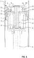
- FIG. 1shows an embodiment of an integrated piston head that includes a hydraulic motor and an electric generator.
- the integrated piston head 1is disposed in a hydraulic cylinder with fluid both above and below the piston head.
- fluidWhen fluid is pressurized above the piston head (with respect to fluid below), fluid flows into one or more inlet/outlet ports 2 above the piston head.
- a positive displacement gerotor 3is utilized as a hydraulic motor, although the present invention(s) is not limited in this regard.
- a pressure differentialforces the gerotor mechanism 3 to spin in its offset pocket.
- the gerotor motor 3is drivingly connected to the generator shaft 8 , which in turn is drivingly connected to an electric generator 5 immersed in the hydraulic fluid such that rotation of the hydraulic motor rotates the electric generator, and vice versa.
- Fluidflows from the inlet/outlet 2 through the hydraulic motor 3 and out the inlet/outlet port (or ports) 4 below the piston head.
- Thisspins the shaft 8 , which spins the generator 5 , which produces electricity.
- Electricityis carried via wires that are routed outside the piston head and damper housing through a hollow piston rod 6 .
- a seal on the outer rim 7 of the piston headprevents fluid from bypassing the inlet/outlet ports by going around the piston head.
- the generator shaft 8is supported at either end by bearings 9 and the shaft 8 supports the inner gerotor element 10 and the rotor 11 of the electrical generator 5 .
- the outer gerotor element 12is supported by a journal bearing 13 .
- a cover plate 14axially locates the gerotor 3 in its pocket in the piston head. Shadow ports 15 may exist in both the piston head and the cover plate so as to keep the gerotor assembly in hydraulic axial balance.
- FIG. 2shows an embodiment of an alternate integrated piston head to that as shown in FIG. 1 .
- a positive displacement gerotor 16is utilized as a hydraulic motor and differs from the embodiment shown in FIG. 1 in the fact that the outer element 17 of the gerotor motor 16 is drivingly connected to the generator 18 via the generator shaft 19 , and the inner element 36 of the gerotor motor 16 is free to rotate on an eccentric shaft 20 .
- This arrangementallows the outer larger diameter element of the gerotor to share a common low friction bearing (such as a deep groove ball bearing or similar) with that of the generator shaft and the smaller inner diameter of the inner element to run directly on its shaft.
- a common low friction bearingsuch as a deep groove ball bearing or similar
- the piston velocity, and hence the gerotor motor velocityis continually accelerating/decelerating in one direction then stopping and then accelerating/decelerating in the opposite direction.
- any hydrodynamic lift generated on the plain bearing of the gerotoris lost, and higher friction on this bearing is applied.
- the larger the diameter of the this bearingthe more torque is lost through this increased friction, and in the application when the gerotor is used as a motor, this torque loss may equal, or even be greater than, the torque generated by the motor itself, potentially causing the motor to stall.
- the low friction bearingBy placing the low friction bearing over, or near, the axial centerline of the outer gerotor element, all, or nearly all, of the radial load generated by the outer gerotor element is passed to the low friction bearing; this may enable the use of a low cost plain bearing on the opposite end of the generator shaft. As shown in FIG. 2 , the diameter of this plain bearing 34 can be reduced to a size significantly smaller than that of the outer gerotor element diameter to reduce its frictional loss.
- the integrated piston head 21is disposed in a hydraulic cylinder with fluid both above and below the piston head.
- fluidWhen fluid is pressurized above the piston head (with respect to fluid below), fluid flows into one or more inlet/outlet ports 22 in the piston head 21 , along flow path 23 .
- a pressure differentialforces the gerotor 16 to spin on the offset journal 24 of the gerotor shaft 20 .
- the outer element 17 of the gerotor motoris drivingly connected to the generator shaft 19 , which in turn is drivingly connected to an electric generator 18 , (which is immersed in the hydraulic fluid) such that rotation of the hydraulic motor rotates the electric generator, and vice versa.
- This fluid flowspins the gerotor which in turn spins the generator shaft 19 , which spins the generator 18 , which produces electricity.
- electricityis transmitted via wires 29 that are routed outside of the piston head and damper housing, through a hollow piston rod 30 that is connected to the generator can 27 , via a high pressure hydraulic seal 31 .
- a seal 32 on the outer rim of the piston headprevents fluid from bypassing the inlet/outlet ports by going around the piston head.
- the generator shaft 19is supported at either end by bearings 33 and 34 with the shaft 19 supporting the outer gerotor element 17 and the rotor 35 of the electrical generator 18 .
- the inner gerotor element 36is supported via a journal bearing 24 on the gerotor shaft 20 .
- the gerotor shaftalso acts as a cover plate to axially locate the gerotor 16 between the gerotor shaft and the piston head 21 . Shadow ports 37 and 38 in both the piston head and the gerotor shaft may be provided so as to keep the gerotor assembly in hydraulic axial balance.
- the port 25 in the gerotor shaftis open to the pressure in the generator can 27 and there is no outer sealing land around this port. Since there is pressure differential between the fluid in port 25 and the generator can 27 an outer sealing land is not necessary, and providing the gerotor with a reduced land contact may reduce the friction drag between the gerotor and the sealing face of the gerotor shaft.
- the opposing shadow port 37 that exists in the piston headis also open to the pressure in the generator can 27 and also has no outer sealing land around this shadow port. This not only helps keep the gerotor in axial hydraulic pressure balance, but it also means that as the fluid flows from the gerotor can into and out of the port 25 , it will also flow via the shadow port 37 . As the fluid flows into and out of the shadow port 37 , it must pass through the rolling elements of the low friction bearing 33 , thereby keeping the bearing running in a continually refreshed supply of fluid and minimizing any localized heating of the fluid due to friction losses.
- the outer gerotor element 17is drivingly connected to the generator shaft via drive pins 39 that are secured into the outer element. These pins are connected to the generator shaft via slots 40 that are disposed around the outer diameter of the generator shaft. In one embodiment these pins are of the split spring type and not only carry the driving torque from the gerotor to the generator shaft but act as small shock arrestors, absorbing the shock loads that are placed in the gerotor from the high frequency motion of the damper.
- the generator shafthas passages 41 that allow the flow from the ports in the gerotor shaft to pass through the generator shaft into the generator can 27 and from there into the volume below the piston head.
- the generator shaftcontains a check valve 42 that allows for a free flow from the piston head through the gerotor, through the shadow port of the generator shaft, through the passages in the gerotor shaft into the generator can and from there into the volume below the piston head, by-passing the gerotor so that reduced damping (and reduced energy recovery) is achieved in the compression stroke.
- the check valveis actuated by a spring 43 ; the preload on the spring can be adjusted so that the compression damping can be varied from a minimum value to a maximum value, whereby maximum compression damping is achieved, to suit different applications.
- the check valvewill not allow flow to by-pass the gerotor on extension stroke so that full extension damping (and energy recovery) may be achieved.
- a blow-off valve 44may be employed to limit the maximum pressure in the generator can and hence the maximum pressure that exists on the bottom side of the integrated piston head (IPH).
- Pressure that exists in the generatorcan acts on a sealing washer 45 via passages 46 .
- the sealing washeris held against the sealing face on the piston head by springs 47 , blocking flow from the passages 46 .
- Pressure acting over the area of the passages 46generates a force to unseat the sealing washer, and once the force from the pressure in the generator can acting on the sealing washer overcomes the spring force from the springs 47 , the sealing washer unseats and allows flow from the generator can and hence the underside of the IPH, to the top side of the IPH, via slots 48 in the piston head (shown in FIG. 2A ), by-passing the gerotor.
- the spring force and the number of passages acting upon the sealing washercan be varied to change the pressure at which the blow-off valve opens, to suit different applications.
- the blow-off valveis used to limit the pressure differential that exists across the gerotor under high extension strokes, so as to not only limit the maximum extension damping force, but to also limit the maximum speed of the gerotor. This will keep the gerotor bearings and generator speeds to reasonable limits under high extension forces, thereby increasing the durability of the IPH.
- FIGS. 3, 3A, 3B and 3Cshow an embodiment of an Integrated Motor/generator Unit (IMGU) that incorporates the features of the embodiment shown in FIG. 2 but in a more compact unit with a reduced number of components.
- IMGUIntegrated Motor/generator Unit
- This embodimentcan be used either in an IPH arrangement, as shown in FIG. 4A , or as an individual ‘valve’ that can be incorporated in a damper or actuator as will be discussed below with respect to FIG. 6 .
- the IMGUmay be used as a generator or as hydraulic power source for elector-hydraulic actuators.
- the outer element of the gerotor motoris drivingly connected to the generator 50 in a similar manner as shown in the embodiment shown in FIG. 2 , the inner element 51 of the gerotor motor is free to rotate on an eccentric shaft 52 .
- This arrangementallows the outer element of the gerotor to share common low friction bearings 53 with that of the generator shaft 54 and the smaller inner diameter of the inner gerotor element to run directly on the eccentric shaft 52 , and offers the efficiency and cost benefits as outlined in the embodiment shown in FIG. 2 .
- the generator 50is now placed concentric and co-planar with the gerotor motor 55 , as opposed to concentric and adjacent as shown in FIG. 2 .
- Magnets 56 of the generatorare drivingly connected (via bonding or other suitable means) directly to the generator shaft 54 (as shown in FIG. 3B ), or can be connected directly to the outer gerotor element 49 , thereby eliminating a separate rotor component.
- Two low friction bearings 53 that support the generator shaftequally share the radial load from the outer gerotor element. As two bearings now equally share this load, substantial increase bearing life may be obtained, increasing the durability of the IMGU.
- the outer bearing races 57 of the low friction bearingsare formed directly into the generator shaft, eliminating the additional component of the outer race, whilst reducing the mass of the IMGU and the rotating inertia of the generator rotating assembly.
- Gerotor caps 58are positioned on either side of the gerotor elements and contain a first flow port 59 and a second flow port 60 ; these ports may be full flow or shadow ports as required by the application, and are such that the gerotor assembly is placed in axial hydraulic balance.
- the port configurationcan be symmetrical about both the vertical and horizontal centerlines.
- the gerotor capsare connected and secured to the IMGU end caps 61 .
- Flow passages 62 and 63 contained in the IMGU end capsconnect to the first and second flow ports in the gerotor caps, so that as fluid flows from the one port to the other, rotation of the gerotor occurs.
- the flow path in and out of the hydraulic unitis on the same side on the IMGU or on opposite sides, thereby increasing the flexibility of use for different applications.
- This symmetrical part configurationalso allows for additional valves and connections, such as by-pass valves pressure relief valves, accumulators etc. to be positioned opposite the first and second flow ports, allowing for flow to occur through the gerotor as well as around the gerotor (i.e. to and from the first and second ports), offering a parallel flow path to the hydraulic unit. Again this may offer favorable packing configurations.
- Additional valvessuch as pressure relief valves, by-pass valves, load holding valves etc. can be incorporated into the gerotor caps and or the IMGU end caps (or even external to the IMGU end caps) to provide additional functionality, both as a generator and as an actuator.
- the inner races 64 of the low friction bearingsare formed directly into the gerotor caps (or into the IMGU end caps) and are axially retained between the gerotor cap and the IMGU end cap. This further reduces the parts count by eliminating the need for a separate bearing inner race.
- the low friction bearingsare of the cylindrical roller type, of course the bearing arrangement shown can be easily changed to incorporate other types of low friction bearings, or even plain bearings, as the application warrants, as the particular application is not limited in this regard.
- the eccentric shaft 52is held stationary to the gerotor caps and the inner gerotor element rotates relative to the shaft supported by a plain journal bearing 65 .
- the eccentric shaftis used to connect and locate the gerotor caps and the IMGU end caps, and the IMGU assembly is secured via a threaded connection 66 , or other arrangement such as swaging and welding. Shoulders 67 on the eccentric shaft ensure an accurate spacing between the gerotor caps is achieved, so that the correct axial clearance is maintained between the gerotor and the end caps, for proper and efficient operation of the gerotor.
- the stator 68 of the generatoris drivingly connected to the outer sleeve 69 (via bonding or other suitable arrangement), and the outer sleeve is sandwiched between the two IMGU end caps so that the stator is held concentric and in correct axial location with the generator shaft.
- a timing feature between the two IMGU end caps and the outer sleeveradially locates the IMGU end caps with respect to each other, to ensure correct timing of the flow ports and positioning of the eccentric shaft 52 .
- the IMGUis used as a cartridge type regenerative valve, whereby the unit is placed in a machined bore or pocket of a device so that flow ports are aligned and sealed against the first and second ports of the IMGU. Flow can then be controlled in a hydraulic circuit by controlling the back EMF of the generator, or the IMGU can act as a hydraulic power source by supplying electrical power to the generator to spin the hydraulic unit so that it acts as a pump. Possible uses of this kind of valve could be as a pressure regulator or relief valve for larger hydraulic circuits.
- variable hydraulic power sourcessuch as for engine or transmission lubrication pumps.
- these pumpsare of fixed displacement and driven at a certain shaft speed.
- These pumpsare sized so as to meet the maximum expected flow demand at any given shaft speed, and as such these pumps supply more flow than is normally required, and energy is wasted through the use of flow control valves.
- Because of the compact size and cylindrical shape of the IMGUit can be used to replace these pumps as a simple cartridge unit inserted into a machined cavity in the engine, transmission etc. or as an externally mounted unit. Because of the variable speed control and hence flow control capability of the IMGU, the output of the pump can be precisely matched to the demand at all times, thereby reducing the energy consumption in these applications.
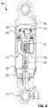
- FIGS. 4 and 4Ashows an embodiment of a monotube damper 10 that utilizes the integrated piston head 1 of FIG. 2 and FIG. 3 respectively, however, the IPH could also be of the configuration as shown in FIG. 1 .
- the integrated piston head 71is disposed in a housing that includes a compression volume 73 and an extension volume 74 .
- a floating piston 75seals a gas-filled accumulator 76 and maintains pressure on the fluid inside the housing.
- fluidflows from the compression volume 73 , through the integrated piston head 71 , and into the extension volume 74 .
- the floating piston 75moves to compress the gas in order to compensate for the volume of the piston rod introduced into the extension volume 74 .
- fluidflows from the extension volume 74 , through the integrated piston head 71 , and into the compression volume 73 .
- the floating piston 75moves to expand the accumulator gas volume 76 to compensate for the piston rod volume leaving the housing during rebound.
- the kinematic characteristics of the dampercan be altered. If the load is increased on the electric generator by applying lower impedance on the terminals, the force/velocity characteristic of the generator will be increased (greater force per angular velocity). Since the hydraulic motor and electric generator are coupled, this is translated to the hydraulic motor and therefore the fluid path through the integrated piston head. The linear relationship results in an increased force/velocity characteristic on the damper piston when lower impedance is applied to the generator, and a decreased force/velocity characteristic on the damper piston when higher impedance is applied to the generator.
- the electric generatorcan be driven as a motor, and the hydraulic motor can be utilized as a hydraulic pump.
- Thisallows for actuation of the damper, creating an active linear actuator.
- An example of such usageusing the embodiment of FIG. 4 as an illustrative example, is to drive the electric motor/generator 18 by applying a voltage.
- a brushed DC motormay be used as the generator and a gerotor pump may be used as the hydraulic motor, however, the present invention(s) is not limited in this regard.
- the hydraulic motor mechanismWhen voltage is applied to the electric generator 18 , the hydraulic motor mechanism will spin, forcing fluid from either the compression volume 73 to the extension volume 74 , or vice-versa, depending on direction of spin (which is governed by voltage polarity for a DC motor/generator). The movement of fluid from one volume to the other forces the piston head to move, actuating the piston rod. In some applications, this may be useful as an active suspension system in vehicles to allow for controllable placement of the wheels for improved ride comfort and terrain traversal characteristics. In some industrial applications, this may be useful as a stand-alone, sealed hydraulic actuator with a high power density characteristic.
- the gas in the accumulator 76should be pressurized so as to ensure the maximal compression (jounce) damping does not exceed the force applied by the accumulator 76 on the compression volume 73 .
- the pressureis typically in the 200-800 psi range, however, an appropriate value can be calculated as follows: accumulator pressure>max jounce damping force/floating piston surface area.
- FIG. 4Ashows a monotube damper of the arrangement shown in FIG. 4 whereby the IPH 71 is of the embodiment as shown in FIG. 3 .
- the IPH 72is connected to a piston head 150 that is connected to the piston rod 30 .
- the seal 151is contained in the piston adaptor, thereby allowing the IPH 72 to be common with other damper arrangements, as shown in FIG. 6 for example. It is of course possible for the seal to be housed directly in the IPH 71 , and the IPH to be connected directly to the piston rod 30 .
- Some embodiments of the described monotube damper incorporating an integrated piston head 1include additional features. Applications such as vehicle dampers sometimes require minimal damping during jounce. In order to reduce the damping during jounce compared to the fluid path through the hydraulic motor, a check valve “bypass” 42 may be incorporated in the integrated piston head (or elsewhere) such that fluid may flow from the compression volume to the extension volume via the bypass valve, but not vice-versa. Additionally, other valving such as non-directional valves, bypasses and blow-off valves 44 may be used to further tune ride characteristics.
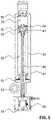
- FIG. 5demonstrates one embodiment of an integrated energy-generating damper that is operated at low pressure, locates the electric generator off the piston head, and features a compression bypass.
- the twin-tube damper embodiment of FIG. 5has a piston head 81 disposed in an inner housing that includes a compression volume 79 and an extension volume 80 .
- the piston 81moves through at least a portion of a jounce stroke to pressurize hydraulic fluid in the compression volume 79 .
- the pistonmoves at least partially through a rebound stroke to pressurize hydraulic fluid in the extension volume 80 .
- An outer tube concentric to the inner tubecontains the low-pressure volume 82 .
- the low-pressure volume 82contains both fluid and a compressible medium (such as gas, foam or bladder).
- the piston head 81 disposed in the inner housingcontains an integrated hydraulic motor 83 that includes a first port 84 and a second port 85 .
- the first port 84is in fluid communication with the compression volume 79 and the second port 85 is in fluid communication with the extension volume 80 .
- the piston rod 86is hollow and contains a shaft 87 that connects the hydraulic motor 83 on the piston head 81 with an electric motor/generator 89 on the other end of the piston rod 86 . Rotation of the hydraulic motor 83 causes rotation of the electric motor/generator 89 .
- rebound dampingis provided by the electric motor/generator 89 and delivered via the shaft 87 inside the piston-rod 86 .
- the resistive force on the shaft 87is delivered to the hydraulic motor 83 to restrict fluid flow between the compression volume 79 and the extension volume 80 .
- the kinematic characteristic of the dampercan be altered by varying the electrical characteristics on the terminals of the electric motor/generator.
- the systemcan be actively driven by supplying power to the electric motor/generator.
- Valves 90 , 91restrict flow into and out of the low-pressure volume 82 such that during jounce fluid flows from the compression volume 79 , through the unrestrictive open valve 90 , and freely flows through the low-pressure volume 82 , through the check valve 91 into the extension volume 80 .
- the check valve 91closes, forcing fluid from the extension volume 80 to go through the piston head 81 , while a small amount of fluid to replace exiting piston rod volume flows from the low-pressure volume 82 , through the open valve 90 , into the compression volume 79 .
- pressurized fluid in the compression volume 79flows through the open valve 90 , into the low-pressure volume 82 , and exits the check valve 91 to the extension volume 80 .
- the volume of fluid entering the open valve 90is greater than that exiting the check valve 91 , and this volume differential is stored in the low-pressure volume by compressing the compressible medium therein.
- some fluidmay pass from the compression volume 79 , through the piston head 81 , into the extension volume 80 , generating electricity in the generator 89 while doing so.
- the embodiment of FIG. 5will pressurize fluid in the extension volume 80 , thereby closing the check valve 91 .
- Fluidis forced to flow from the extension volume 80 , through the piston head 81 , into the compression volume 79 .
- stored fluid in the low-pressure volume 82will flow through the open valve 90 into the compression volume 79 to replace piston rod volume as the compressible medium in the low-pressure volume 82 expands.
- the hydraulic motor 83spins. This spins the shaft 87 that runs inside the piston rod 86 and the motor/generator 89 so that this fluid flow generates back electromotive force (EMF) from the motor/generator to provide damping.
- EMFelectromotive force
- an offset loop 93is used to attach the piston rod 86 to the vehicle, however, any suitable attachment method may be employed such as loop connectors or threaded piston rod mounts.
- the electric generatoris placed above the mount point for the piston rod.
- the shaft 87passes through a shaft seal that separates a fluid-contained side of the shaft from an open-air side of the shaft. In one instance, this allows a keyed shaft 87 to insert into the electric generator can 92 which can thread onto the piston rod, acting as the primary mount apparatus for the piston rod end of the damper.
- an offset loop adapteris used on the top and bottom to allow a bolt-on attachment without side-loading the damper.
- shaft 87 and the generator 92can be enclosed in fluid during production, eliminating the need for a pressure shaft seal for field installation.
- an adaptercan be attached to the piston rod to allow for either an eyelet mount point or a piston rod nut mount attachment method without the need for threading on the generator can during installation. Again, this allows for the elimination of a friction-causing shaft seal on the motor shaft 87 .
- FIG. 6demonstrates another embodiment of an integrated energy-generating damper that is operated at low pressure, locates the electric generator off the piston head, and features a compression bypass, similar to that shown in FIG. 5 , differing in the fact that the motor/generator is not disposed on the opposite end of the piston rod from the piston head, but positioned perpendicular to the cylinder body.
- This arrangementoffers the benefit of shorter overall shock length, as well as eliminating the need for long thin concentric shafts. This arrangement may be more suitable for vehicular damper applications where shock length and packaging requirements are constrained.
- the twin-tube damper embodiment of FIG. 6includes a piston 94 disposed in an inner housing that includes a compression volume 95 and an extension volume 96 .
- the piston 94moves through at least a portion of a jounce stroke to pressurize hydraulic fluid in the compression volume 95 .
- the pistonmoves at least partially through a rebound stroke to pressurize hydraulic fluid in the extension volume 96 .
- An outer tube concentric to the inner tubecontains the low-pressure volume 97 .
- the low-pressure volume 97contains both fluid and a compressible medium 98 (such as gas, foam or bladder).
- An integrated motor/generator unit (IMGU) 72is located at the rod end of the damper. The IMGU shown in FIG.
- FIG. 6is similar to that as shown in FIG. 3 , but it may be similar to that as shown in FIG. 1 or FIG. 2 , and includes a first port 100 and a second port 101 .
- the first port 100is in fluid communication with the low pressure volume 97 and the second port 101 is in fluid communication with the extension volume 96 .
- a valve 102restricts flow into and out of the low-pressure volume 97 such that during jounce fluid flows from the compression volume 95 , through the valve 102 , and into the low-pressure volume 97 .
- the valve 102offers the required flow resistance in this direction so as to give the appropriate jounce damping characteristics for the application.
- the valve 102allows for free flow from the low-pressure volume 97 into the compression volume 95 .
- pressurized fluid in the compression volume 95flows through the valve 102 , into the low-pressure volume 97 , into the IMGU 72 through port 100 , exiting the IMGU through port 101 and into the extension volume 96 .
- the volume of fluid exiting the compression volume 95is greater than that entering the extension volume 96 and this volume differential is stored in the low-pressure volume 97 by compressing the compressible medium 98 therein.
- the embodiment of FIG. 6will pressurize fluid in the extension volume 96 forcing flow from the extension volume 96 , through the IMGU 72 via ports 101 and 102 , into the low pressure volume 97 , through the open valve 102 into the compression volume 95 .
- stored fluid in the low-pressure volume 97will also flow through the open valve 102 into the compression volume 95 to replace piston rod volume, as the compressible medium 98 in the low-pressure volume 97 expands.
- the hydraulic motor 55 and generator 50spins. This generates back electromotive force (EMF) from the motor/generator to provide damping and produces electricity as described in FIG. 2 .
- EMFback electromotive force
- the kinematic characteristic of the dampercan be altered by varying the electrical characteristics on the terminals of the electric motor/generator.
- the systemcan be actively driven by supplying power to the electric motor/generator.
- fluid that flows from the compression volume 95 through the valve 102 into the low-pressure volume 97then flows into the IMGU 72 through port 100 , exiting the IMGU through port 101 and then into the extension volume 96 .
- the fluid that flows through the IMGU during the jounce strokewill cause the motor 55 and generator 50 to spin, and although no back EMF will be produced, because of the low jounce damping forces required, the parasitic losses from the fluid flow and the rotating parts may cause too high a jounce damping force for certain applications.
- the check valvewill allow the fluid to free flow directly from the low pressure volume 97 to the compression volume 96 , thereby reducing the jounce damping force, but will not allow flow to bypass the IMGU during rebound damping.
- FIG. 6there is a volume of oil that becomes trapped between the pockets 103 of the piston 94 and the journals 104 of the end caps during the last portion of both the jounce and rebound strokes.
- the piston 94is stroked so that the journal 104 enters the pocket 103 (in either jounce or rebound strokes) the hydraulic fluid that is trapped in the pocket 103 is forced to flow out of the annular gap that is formed between the journal outside diameter and the pocked inside diameter.
- the annular gapis sized so that a pressure spike is produced acting over the pocket area producing an additional force to provide a hydraulic buffer at the end of both the jounce and rebound strokes.
- the clearance between the pockets 103 and the journal 104can be selected so as to produce the correct amount of buffering to suit the application.
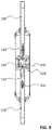
- an energy-generating damperthat is not gas-pressure limited in compression damping, features energy capture in both compression and rebound, and maximizes stroke length per body length.
- a tri-tube damper designthat incorporates an energy-harvesting IMGU is disclosed.
- a piston rod 105 and hydraulic-ram type (solid) piston 106are disposed in an inner fluid-filled cylinder 107 .
- the inner housing(collectively, the compression volume 108 and the extension volume 109 ) is surrounded by a second tube 110 that is concentric to the inner tube 107 .
- the space between the inner tube and the second tubecontains the high-pressure volume 111 .
- the second tube 110is surrounded by a third tube 112 that is concentric to the second tube.
- the space between the second tube and the third tubecontains the low-pressure volume 112 .
- the high-pressure and low-pressure tubesmay be reversed.
- an integrated motor/generator unit (IMGU) 72is located at the rod end of the damper.
- the IMGU shown in FIG. 7is similar to that as shown in FIG. 3 , alternatively, it may be similar to that as shown in FIG. 1 or FIG. 2 , and includes a first port 113 and a second port 114 .
- the first port 113is in fluid communication with the high-pressure volume 111 and the second port 114 is in fluid communication with the low-pressure volume 112 .
- the piston rod 105pushes the piston 106 into the compression volume 108 , this forces fluid to pass from the compression volume into the high pressure volume 111 via a directional check valve 115 .
- the high pressure volume 111is in fluid communication with the first port 113 of the IMGU 72 . Fluid passes from the high pressure volume 111 , through the first port 113 , through the IMGU 72 , and out the second port 114 , into the low pressure volume 112 , through a directional check valve 116 , and into the extension volume 109 .
- a compressible medium 117such as foam cell, or bladder, in the low-pressure volume 112 compresses to displace introduced piston rod volume.
- the piston rod 105pulls the piston 106 into the extension volume 109 , this forces fluid to pass from the extension volume into the high pressure volume 111 via a directional check valve 118 .
- the high pressure volume 111is in fluid communication with the first port 113 of the IMGU 72 . Fluid passes from the high pressure volume 111 , through the first port 113 , through the IMGU 72 , and out the second port 114 , into the low pressure volume 112 , through a directional check valve 119 , and into the compression volume 108 . Simultaneously, the compressible medium 117 in the low-pressure volume 112 decompresses to replace extracted piston rod volume.
- the hydraulic motor 55 and generator 50rotate. This generates back electromotive force (EMF) from the motor/generator to provide damping and produces electricity as described in the embodiment of FIG. 2 .
- EMFback electromotive force
- the kinematic characteristic of the dampercan be altered by varying the electrical characteristics on the terminals of the electric motor/generator.
- the systemcan be actively driven by supplying power to the electric motor/generator.
- FIG. 8shows a twin-tube design that is not gas-pressure limited, featuring bidirectional energy capture, and having a high stroke to body length ratio.
- This systemutilizes the integrated piston head of FIG. 2 (although this could also be the IPH as shown in FIG. 1 or 3 ), in a twin-tube body design with the use of a valve mechanism that operates to ensure that whichever port is at low pressure is always connected to the accumulator. Pilot operated valves such as check valves or a three port pilot operated spool valve may accomplish this operation.
- a shuttle valvecan also ensure that the gas accumulator 124 on the common port is always in fluid communication with the low-pressure side of the piston head.
- an integrated piston head 71is disposed in an inner cylinder containing hydraulic fluid.
- the extension volume 120 of the inner cylinderis in fluid communication with an outer fluid volume 121 which is housed between the inner cylinder and a concentric outer cylinder.
- Both the compression volume 122 and the outer fluid volume 121are in fluid connection with a pilot-operated valve block 123 .
- a gas-filled accumulator, or reservoir, 124is also in fluid connection with the pilot-operated valve block 123 .
- the piston rod 30is pushed into the cylinder, forcing fluid from the compression volume 122 through the hydraulic motor 16 , which spins an electric motor/generator 18 , and passes into the extension volume 120 .
- Electricity from the electric generatorpasses down wires that go through the center of the piston rod 30 .
- High-pressure wirepass-throughs seal the fluid portion of the internal shock body from the outside. Since the jounce stroke introduces piston rod volume into the extension volume, fluid needs to be displaced from the extension volume to an accumulator 124 , which occurs via a valve block 123 .
- a pilot operated check valve 125is opened in the valve block 123 via the pilot line 127 . This allows free flow to and from the accumulator 124 to the extension volume 120 , thereby allowing the introduced rod volume to flow from the extension volume into the accumulator 124 .
- the piston rod 30is pulled out of the cylinder, forcing fluid from the extension volume 120 through the hydraulic motor 16 , which spins an electric motor/generator 18 , and passes into the compression volume 122 . Since the rebound stroke extracts piston rod volume from the compression volume, fluid needs to be displaced from the accumulator 124 , which occurs via a valve block 123 . As the rod volume will need to be replaced into the compression volume from the accumulator, the pressure in the compression volume will be lower than that of the accumulator, this will allow for fluid to flow from the accumulator 124 through the check valve 126 into the compression volume 122 .
- the valve block 123comprises of a check valve 126 and a pilot operated check valve 125 to ensure that whichever port of the IPH is at low pressure is always connected to the accumulator, however, this can also be achieved using other valving arrangements such as a spool valve mechanism that can switch the connection of the accumulator 124 between the compression volume 122 and the extension volume 120 so that the accumulator is always in fluid communication with the lower pressure volume.
- a spool valve mechanismthat can switch the connection of the accumulator 124 between the compression volume 122 and the extension volume 120 so that the accumulator is always in fluid communication with the lower pressure volume.
- an internal pilot port in the valve block 123connected to the compression volume 122 pushes the shuttle mechanism such that fluid can communicate between the accumulator 124 and the extension volume 120 .
- FIG. 8can also be constructed with the piston head, piston rod, and electric motor/generator configuration of FIG. 5 , where the piston head contains a hydraulic motor, the piston rod contains an internal spinning shaft, and the electric motor/generator is on the opposing side of the piston rod.
- the system of FIG. 8can be constructed with a solid piston head and a hydraulic motor and generator pair that sits at the base of, and external to, the damper such as the system disclosed in FIG. 6 .
- the first port of the hydraulic motorwould be in fluid communication with the compression volume 122 and second port would be in fluid communication with the extension volume 120 (via the outer fluid volume 121 ).
- the rest of the system including the valve block 123may remain as shown in FIG. 8 .
- FIG. 9a through-shaft integrated piston head system is demonstrated.
- an integrated piston head 128is disposed in a cylinder containing hydraulic fluid connected to a first piston rod 129 and a second piston rod 130 .
- the piston head as shown in FIG. 9is similar to that as shown in FIG. 3 , but it may be similar to that as shown in FIG. 1 or FIG. 2 .
- the second piston rod 130 exiting the devicemay be connected to a spring mechanism in order to return the other piston rod to a normally compressed state.
- fluid from the first volume 131is forced to flow through the hydraulic motor 132 , which spins an electric motor/generator 133 , and passes into the second volume 134 .
- Electricity from the electric generatorpasses down wires that go through the center of one of the piston rods where high-pressure wire pass-throughs seal the fluid portion of the internal shock body from the outside.
- fluid from the second volume 134is forced to flow through the hydraulic motor 132 , which spins an electric motor/generator 133 , and passes into the first volume 131 .
- a device to displace fluid to compensate for fluid volume changes due to temperature fluctuationsInternal to the system is a device to displace fluid to compensate for fluid volume changes due to temperature fluctuations.
- thisis shown to be compressible foam cell inserted into a crevice 135 in one of the piston rods 134 .
- placement of the fluid compensation mechanismmay be in another location internal to the unit or external.
- an accumulatoramong other devices, can be used as a replacement or in addition to foam in order to displace fluid.
- a shuttle valvemay be employed as described in FIG. 8 .
- FIG. 10demonstrates such as system whereby an Integrated Motor/generator Unit (IMGU) is connected to a rotary damper unit 136 .
- IMGUIntegrated Motor/generator Unit
- the IMGU 72is similar to that as shown in FIG. 3 , but it may be similar to that as shown in FIG. 1 or FIG. 2 .
- the damper lever stroke in a first directionfluid from the first volume(s) 138 is forced to flow into the first port 59 through the hydraulic motor 55 and out through the second port 60 into the second volume(s) 139 .
- the motor and generatorspins and generates electricity, as described in FIG. 7 .
- fluid from the second volume(s) 139is forced to flow into the second port 60 through the hydraulic motor 55 and out through the first port 59 into the first volume(s) 138 .
- the motor and generatorspins and generates electricity, as described in FIG. 7 .
- a device to displace fluid to compensate for fluid volume changes due to temperature fluctuationsmaybe incorporated either internally or externally by way of a compressible foam cell or an accumulator, among other devices.
- the IMGUis shown as an external device to the rotary damper, however, the IMGU can be easily integrated into rotary damper mechanism, thereby reducing the overall package size and eliminating external hydraulic connections.
- electro hydraulic linear actuatoroffers the ability to capture energy in the opposite direction to their actuation, such as in lifting equipment where a mass is being raised and then lowered.
- FIG. 11 and FIG. 11Aa twin-tube energy harvesting electro hydraulic linear actuator that is capable of capturing energy in the compression stroke and power actuation in the extension stroke is presented.
- the IPH valveis placed at the base of the actuator concentric with the actuator, it is possible to locate the IPH valve at the base of the actuator body, but perpendicular to the axis of the actuator as shown in the embodiment shown in FIG. 11A , (the IPH valve may also be placed at the base of the actuator body, but parallel to the actuator axis). This may offer packaging benefits in certain applications where actuator length is critical.
- the twin-tube embodiments of FIG. 11 and FIG. 11Ahave a piston 140 disposed in an inner housing 141 that includes a compression volume 142 and an extension volume 143 .
- the compression volume 142is pressurized and moves the piston 140 through at least a portion of an extension stroke to overcome a force.
- the pistonmoves at least partially through a compression stroke to pressurize hydraulic fluid in the compression volume 142 from a force.
- An outer tube 144 concentric to the inner tube 141contains a low-pressure volume 145 that is in fluid communication with the extension volume via passages 146 .
- the low-pressure volume 145contains both fluid and a compressible medium 147 (such as gas, foam or bladder).
- An integrated piston head (IPH) assembly 71( 72 in FIG. 11A ) is located at the base of the actuator.
- the IPH assemblymay be similar to that as shown in FIG. 1 , FIG. 2 or FIG. 3 , and includes a first port 148 and a second port 149 .
- the first port 148is in fluid communication with the compression volume 142 and the second port 149 is in fluid communication with the low pressure volume 145 .
- poweris supplied to the electric motor/generator 18 causing it and the hydraulic motor 16 to spin, this causes fluid to flow from the hydraulic motor via port 148 into the compression volume 142 .
- a load holding valve(such as a check valve) may be placed between the first port 148 and the compression volume 142 to eliminate leakage through the hydraulic motor when the actuator is under load holding operation. This will prevent the piston from retracting under load holding causing a safety hazard.
- the load holding valvemight be of the pilot operated, electronically activated or mechanically activated type, these valves are well known in the art and the patent is not limited in this regard.
- retraction of the pistonmay be accomplished in two ways, in the first mode, where there exists an external load on the piston rod (when the actuator is used in lowering a payload for example); the piston will want to retract under this force. If a load holding valve is used then the piston will not retract until this valve is activated to allow fluid flow from the compression volume 142 to the first port 148 . Once this valve is activated (via electronic, mechanical means etc.), then fluid will flow from the compression volume 142 to the first port 148 , due to the load place upon the piston rod, and will cause the motor 16 to spin. This will cause the generator 18 to spin generating back electromotive force (EMF) from the motor/generator to provide resistance to this flow, and producing electricity as described in FIG. 2 .
- EMFback electromotive force
- a controllermay provide varying impedance to the electric generator, thereby controlling rate at which the fluid flows from the compression volume to the first port, offering a controllable and safe manner in which to lower the payload.
- the pistonIn the second mode where there is no payload acting on the actuator, the piston is retracted by supplying power to the electric motor/generator 18 causing the electric motor/generator 18 and the hydraulic motor 16 to spin, this causes fluid to flow from the from the compression volume 142 to the first port 148 , pressurizing the low pressure volume 145 and the extension volume 143 , thereby retracting the piston 140 .
- thiswill require the low pressure volume to become pressurized, the load to retract the piston in this application will be very low, as it will need to only overcome friction of the actuator and any accompanying mechanism, and as such the pressure attained in the low pressure volume will be within the limits of the compressible medium contained therein. If a load holding valve is utilized as described above, then actuation of this valve will first have to take place before the piston is retracted.
- the volume displaced by the compression volumeis greater than that entering the extension volume and this volume differential is stored in the low-pressure volume 145 by compressing the compressible medium 147 therein.
- Certain applications of the energy harvesting electro hydraulic linear actuator as shown in the embodiment of FIGS. 11 and 11Amay require the addition of other valves such as pressure relief valves, thermal relief valves etc. and the incorporation of these valves are well known in the art of this type of actuator and the patent is not limited in this regard.
- the motor/generator assemblymay be advantageous to keep the motor/generator assembly rotating in the same direction regardless of stroke direction.
- the actuatorbe it a linear or rotary type
- a rectifying valve circuitIn the embodiment shown in FIG. 12 an energy harvesting linear actuator that is connected to an integrated motor/generator assembly via a rectifying valve circuit is presented.
- the rectifying valve circuit 150is in the form of four check valves, however, the same functionality can of course be achieved by the use of a pilot operated spool valve(s) or the like, and the patent is not limited in this regard.
- the integrated motor/generator assemblyis similar to that as shown in FIG. 3 , but it may be similar to that as shown in FIG. 1 or FIG. 2 , and includes a first port 151 and a second port 152 .
- the first port 151is in fluid communication with the discharge side of the rectifying circuit and the second port 152 is in fluid communication return side of the rectifying circuit.
- the linear actuatoris in the form of a twin tube architecture which has a first port 153 that is in fluid connection with the extension side of the actuator and a second port 154 is in fluid connection with the compression side.
- a piston 155disposed in an inner housing that includes an extension volume 156 and a compression volume 157 .
- the piston 155moves through at least a portion of an extension stroke to pressurize hydraulic fluid in the extension volume 156 .
- the pistonmoves at least partially through a compression stroke to pressurize hydraulic fluid in the compression volume 157 .
- An outer tube concentric to the inner tubeconnects the compression volume 157 to the second port 154 .
- the rectifying circuitis configured so that fluid that is discharged from the first port of the actuator during an extension stroke or the second port during a compression stroke will always be diverted to the discharge side of the rectifying circuit and into the first port of the IMGU 72 , and fluid discharged from the second port 152 of the IMGU will always be diverted to the first port 153 of the actuator during a compression stroke or the second port 154 during an extension stroke. This will ensure that the direction of rotation of the motor/generator will remain constant regardless of whether the actuator is extended or retracted under load.
- An accumulator or reservoir 158is connected to the second port 152 of the IMGU 72 to accommodate the difference in volume from the extension and compression strokes.
- the reservoiris connected to the symmetrical port opposite the second port 152 , although this could be connected anywhere along the return line of the rectifying circuit.
- FIGS. 13 and 13Aan integrated motor/generator unit, comprising of an axial piston unit positioned concentric and coplanar with the generator is shown.
- This embodimentis similar to that shown in FIG. 3 , but the hydraulic unit is now an axial piston unit (i.e. a swashplate unit) as opposed to a gerotor pump.
- a swashplate pumpmay offer high performance, in terms of pressure capacity, speed, efficiency and durability, when compared to other types of hydraulic pumps.
- the cylinder block 160 of the axial piston unit 159is drivingly connected to the magnets 161 of the generator 162 and is supported by bearings 163 to the end caps 164 and 165 .
- the end cap 163contains a first port 166 and second port 167 that are arranged to act as a commutation plate to direct flow into and out of the cylinder block 160 via passages 168 .
- a swashplate 169is located opposite the cylinder block passages 168 on the end cap 165 .
- a plurality of pistons 170are contained within the bores of the cylinder block 160 and are held against the swashplate by the piston feet 171 .
- variable displacement axial piston pumpsexist, and whilst they have the advantage of being able to control the flow rate to meet the demand, they all have the disadvantage that as their swept displacement approaches zero, their volumetric efficiency decreases.
- an axial piston pumpwhich is of equal or smaller size than a variable displacement axial piston pump, will be able to offer a variable flow rate whilst remaining at its maximum swept displacement, thereby maintaining its volumetric displacement.
- a tri-tube damper designthat incorporates an energy-harvesting IMGU is disclosed.
- a piston rod 172 and hydraulic-ram type (solid) piston 173are disposed in an inner fluid-filled cylinder 174 .
- the inner housing(collectively, the compression volume 175 and the extension volume 176 ) is surrounded by a second tube 177 that is concentric to the inner tube 174 .
- the space between the inner tube and the second tubecontains the high-pressure volume 178 .
- the second tube 177is surrounded by a third tube 179 that is concentric to the second tube.
- the space between the second tube and the third tubecontains the low-pressure volume 180 .
- the high-pressure and low-pressure tubesmay be reversed.
- an integrated motor/generator unit (IMGU) 72is side located at the base end of the damper and in the embodiment of FIG. 14A , an integrated motor/generator unit (IMGU) 72 is located at the base end of the damper.
- the IMGU shown in FIG. 14 and FIG. 14Ais similar to that as shown in FIG. 3 , alternatively, it may be similar to that as shown in FIG. 1 or FIG. 2 , and includes a first port 181 and a second port 182 .
- the first port 181is in fluid communication with the high-pressure volume 178 and the second port 182 is in fluid communication with the low-pressure volume 180 .
- the piston rod 172pushes the piston 173 into the compression volume 175 , the fluid in the compression volume 175 is blocked from flowing into the low pressure volume by a directional check valve 183 , and is forced to flow from the compression volume 175 into the extension volume 176 via a directional check valve 184 contained in the piston 173 .
- the volume differentialpasses through the high pressure volume 178 into the first port 181 of the IMGU 72 , and out the second port 182 , into the low pressure volume 180 .
- a compressible medium 185such as foam cell, or bladder, or gas volume in the low-pressure volume 180 compresses to displace introduced piston rod volume.
- the piston rod 172pulls the piston 173 into the extension volume 176 , the fluid in the extension volume 176 is blocked from flowing into the low compression volume by the directional check valve 184 and is forced to pass from the extension volume into the high pressure volume 180 .
- the high pressure volume 180is in fluid communication with the first port 181 of the IMGU 72 . Fluid passes from the high pressure volume 180 , through the first port 181 , through the IMGU 72 , and out the second port 182 , into the low pressure volume 180 , through a directional check valve 183 , and into the compression volume 175 . Simultaneously, the compressible medium 185 in the low-pressure volume 180 decompresses as fluid passes from the low pressure chamber 180 through the directional check valve 183 into the compression volume to replace the extracted piston rod volume.
- the hydraulic motor 55 and generator 50rotate. This generates back electromotive force (EMF) from the motor/generator to provide damping and produces electricity as described in the embodiment of FIG. 2 .
- EMFback electromotive force
- the kinematic characteristic of the dampercan be altered by varying the electrical characteristics on the terminals of the electric motor/generator.
- the damping force of the systemcan be increased beyond the range of that offered by the back EMF under power regeneration mode, or decreased below that offered by the resistance from the system open-circuit parasitic losses.
- the motor/generatorcan be driven so that the fluid flow from the hydraulic motor resists fluid flow from the damper, in either compression or rebound, thereby increasing the damper force, or it can be driven so that the fluid flow from the hydraulic motor assists fluid flow from the damper, in either compression or rebound, thereby decreasing the damper force.
- the motor/generatorcan also be driven so that the fluid flow from the hydraulic motor resists fluid flow from the damper to the point that the damper is held stationary.
- the dampercannot be actively driven so that the damper will extend or retract from power being supplied to the motor/generator.
- the present inventionis not limited in this regard, however, and when used in a monotube configuration, for example, is able to extend and retract from power being supplied to the motor/generator without additional valving.
- the motor/generatoris driven to extend the damper, fluid flow from the second port 182 will free flow through the check valves 183 and 184 back into the first port 181 , and if motor/generator is driven to retract the damper then fluid flow from the first port 181 will pressurize the extension chamber 176 , which will in turn pressurize the compression chamber 175 , however the check valve 183 will block any flow from the compression chamber thereby not allowing retraction of the piston rod.
- FIG. 15a tri-tube damper design that incorporates an energy-harvesting IMGU 72 similar to that shown in FIG. 14 is disclosed (alternatively, it may be similar to that shown in FIG. 14A ).
- controlled valves 186 and 187are incorporated to allow the damper to be actively extended or retracted by supplying power to the motor/generator.
- the controlled valves 186 and 187may be controlled electronically or hydraulically or by other means.
- the integrated systems disclosed hereinmay be used in conjunction with passive damping, either in parallel with bypass valves, or in series with the hydraulic motor.
- Passive valvingis well known in the art, often incorporating shim stacks, directional valves, and spring-loaded fluid-restrictive porting.
- Bypass pathsmay allow for either lower damping than the viscous losses through the hydraulic motor can allow, or to tune subtle ride characteristics, however, the present invention(s) is not limited in this regard.
- Series valvingmay allow for higher damping than the electric generator can provide in full saturation (at very high velocities), a requirement especially important in heavy duty use scenarios such as military dampers.
- Parallel or series dampingcan be incorporated directly on the piston head, in external bypass tubes, in base valves, or elsewhere.
- the dynamic range required by the dampermay be beyond that which can be reasonably supplied by the hydraulic motor and generator.
- the integrated systems disclosed hereinmay be used in conjunction with one or more active/controlled valves, either in parallel or in series (or a combination of both) with the hydraulic motor.
- one or more active/controlled valvesmay be used separately or in combination with one or more passive valves.
- the active/controlled valvesmay be adapted to operate at a predetermined pressure. The predetermined pressure may be varied according to the operating needs of the damper, hydraulic motor, or generator. In addition, the pressure may be selected to dynamically increase or decrease the damping range beyond that which can be supplied by the hydraulic motor and generator.
- One or more of the active/controlled valvesmay be controlled electrically or by some form of mechanical or hydro-mechanical actuation.
- one or more active/controlled valvesmay be adapted to provide a unidirectional flow of fluid.
- flowcan be diverted by an externally controllable means to bypass the hydraulic motor to lower damping forces by reducing the viscous losses through the hydraulic motor.
- flowcan be restricted either into or out of the hydraulic motor by an externally controllable means to increase the damping forces beyond which the generator can supply at full saturation.
- These valvescan be incorporated directly on the piston head, externally in base valves, or elsewhere.
- additional control valvessuch as load holding valves, pressure limiting valves, etc. may be incorporated to provide different functionality as required by the application.
- a controllermay provide a varying impedance to the electric generator to control the force response of the damper based on various parameters such as velocity or position, while simultaneously capturing energy associated with movement in the damper.
- the force responsemay follow an equation or a lookup table based on such parameters.
- This level of controlis called semi-active damping, as the amount of damping is controlled, but the system is not actuated.
- the electric motor/generator in the dampercan be actuated to allow for fully-active control.
- the integrated systems disclosed hereinmay be used in an autonomous fashion where the controller bootstraps power from the energy-harvesting damper.
- Thisallows for either a semi-active damper, or in some embodiments, an active damper that generates electricity and uses the electricity to power its own control circuitry.
- Such a systemmay allow for easy vehicle retrofits with the improved semi-active or fully-active suspensions without the requirement of running wires along the vehicle chassis.
- a bootstrap capacitoris tied to the output of the energy generating damper. As the damper generates electricity, the capacitor is charged. Meanwhile, the controller's power input is connected in parallel to this capacitor. As soon the bootstrap capacitor reaches some voltage threshold, the controller turns on and begins controlling the kinematic characteristic on the damper by using its own generated electricity. Capacitors or a small battery can be used on the input of the controller to filter transient voltage inputs.
Landscapes
- Engineering & Computer Science (AREA)
- General Engineering & Computer Science (AREA)
- Mechanical Engineering (AREA)
- Chemical & Material Sciences (AREA)
- Combustion & Propulsion (AREA)
- Hydraulic Motors (AREA)
- Fluid-Damping Devices (AREA)
- Fluid-Pressure Circuits (AREA)
- Vehicle Body Suspensions (AREA)
- Vibration Prevention Devices (AREA)
- Rotary Pumps (AREA)
Abstract
Description
Claims (16)
Priority Applications (2)
| Application Number | Priority Date | Filing Date | Title |
|---|---|---|---|
| US16/850,122US11499535B2 (en) | 2010-06-16 | 2020-04-16 | Integrated energy generating damper |
| US17/964,295US12264656B2 (en) | 2010-06-16 | 2022-10-12 | Integrated energy generating damper |
Applications Claiming Priority (8)
| Application Number | Priority Date | Filing Date | Title |
|---|---|---|---|
| US35518610P | 2010-06-16 | 2010-06-16 | |
| US201161467161P | 2011-03-24 | 2011-03-24 | |
| PCT/US2011/040654WO2011159874A2 (en) | 2010-06-16 | 2011-06-16 | Integrated energy generating damper |
| US201313704138A | 2013-03-11 | 2013-03-11 | |
| US14/681,630US9689382B2 (en) | 2010-06-16 | 2015-04-08 | Integrated energy generating damper |
| US15/620,032US10495073B2 (en) | 2010-06-16 | 2017-06-12 | Integrated energy generating damper |
| US16/458,845US10655612B2 (en) | 2010-06-16 | 2019-07-01 | Integrated energy generating damper |
| US16/850,122US11499535B2 (en) | 2010-06-16 | 2020-04-16 | Integrated energy generating damper |
Related Parent Applications (1)
| Application Number | Title | Priority Date | Filing Date |
|---|---|---|---|
| US16/458,845ContinuationUS10655612B2 (en) | 2010-06-16 | 2019-07-01 | Integrated energy generating damper |
Related Child Applications (1)
| Application Number | Title | Priority Date | Filing Date |
|---|---|---|---|
| US17/964,295ContinuationUS12264656B2 (en) | 2010-06-16 | 2022-10-12 | Integrated energy generating damper |
Publications (2)
| Publication Number | Publication Date |
|---|---|
| US20200408199A1 US20200408199A1 (en) | 2020-12-31 |
| US11499535B2true US11499535B2 (en) | 2022-11-15 |
Family
ID=45348861
Family Applications (7)
| Application Number | Title | Priority Date | Filing Date |
|---|---|---|---|
| US13/704,138Active2031-11-27US9035477B2 (en) | 2010-06-16 | 2011-06-16 | Integrated energy generating damper |
| US13/759,467ActiveUS8841786B2 (en) | 2010-06-16 | 2013-02-05 | Integrated energy generating damper |
| US14/681,630Active2031-07-19US9689382B2 (en) | 2010-06-16 | 2015-04-08 | Integrated energy generating damper |
| US15/620,032Active2032-01-12US10495073B2 (en) | 2010-06-16 | 2017-06-12 | Integrated energy generating damper |
| US16/458,845ActiveUS10655612B2 (en) | 2010-06-16 | 2019-07-01 | Integrated energy generating damper |
| US16/850,122Active2031-07-07US11499535B2 (en) | 2010-06-16 | 2020-04-16 | Integrated energy generating damper |
| US17/964,295Active2032-06-01US12264656B2 (en) | 2010-06-16 | 2022-10-12 | Integrated energy generating damper |
Family Applications Before (5)
| Application Number | Title | Priority Date | Filing Date |
|---|---|---|---|
| US13/704,138Active2031-11-27US9035477B2 (en) | 2010-06-16 | 2011-06-16 | Integrated energy generating damper |
| US13/759,467ActiveUS8841786B2 (en) | 2010-06-16 | 2013-02-05 | Integrated energy generating damper |
| US14/681,630Active2031-07-19US9689382B2 (en) | 2010-06-16 | 2015-04-08 | Integrated energy generating damper |
| US15/620,032Active2032-01-12US10495073B2 (en) | 2010-06-16 | 2017-06-12 | Integrated energy generating damper |
| US16/458,845ActiveUS10655612B2 (en) | 2010-06-16 | 2019-07-01 | Integrated energy generating damper |
Family Applications After (1)
| Application Number | Title | Priority Date | Filing Date |
|---|---|---|---|
| US17/964,295Active2032-06-01US12264656B2 (en) | 2010-06-16 | 2022-10-12 | Integrated energy generating damper |
Country Status (5)
| Country | Link |
|---|---|
| US (7) | US9035477B2 (en) |
| EP (3) | EP2582976B1 (en) |
| JP (6) | JP5723445B2 (en) |
| CN (2) | CN105386951B (en) |
| WO (1) | WO2011159874A2 (en) |
Cited By (1)
| Publication number | Priority date | Publication date | Assignee | Title |
|---|---|---|---|---|
| US12264656B2 (en) | 2010-06-16 | 2025-04-01 | ClearMotion, Inc. | Integrated energy generating damper |
Families Citing this family (82)
| Publication number | Priority date | Publication date | Assignee | Title |
|---|---|---|---|---|
| US8807258B2 (en) | 2008-03-11 | 2014-08-19 | Physics Lab Of Lake Havasu, Llc | Regenerative suspension with accumulator systems and methods |
| US8839920B2 (en) | 2008-04-17 | 2014-09-23 | Levant Power Corporation | Hydraulic energy transfer |
| US10279641B2 (en) | 2008-04-17 | 2019-05-07 | ClearMotion, Inc. | Distributed active suspension with an electrically driven pump and valve controlled hydraulic pump bypass flow path |
| ITPI20110052A1 (en)* | 2011-05-03 | 2012-11-04 | Giorgio Cuce | HYDRAULIC DAMPING STRUCTURE |
| US9295598B2 (en)* | 2011-12-09 | 2016-03-29 | Stryker Corporation | Patient support backrest release and actuator assembly |
| TWI541437B (en)* | 2012-08-31 | 2016-07-11 | 國家中山科學研究院 | Vibration energy recovery device |
| KR101416362B1 (en)* | 2012-11-15 | 2014-08-07 | 현대자동차 주식회사 | Energy regeneration device of suspension system for vehicle |
| EP2756973B1 (en)* | 2013-01-17 | 2018-07-04 | ContiTech USA, Inc. | Energy transforming unit for distance measurement sensor |
| US9303715B2 (en) | 2013-03-10 | 2016-04-05 | Oshkosh Defense, Llc | Limiting system for a vehicle suspension component |
| US8991840B2 (en)* | 2013-03-14 | 2015-03-31 | Oshkosh Defense, Llc | Load dependent damper for a vehicle suspension system |
| US9702349B2 (en) | 2013-03-15 | 2017-07-11 | ClearMotion, Inc. | Active vehicle suspension system |
| WO2014152482A2 (en) | 2013-03-15 | 2014-09-25 | Levant Power Corporation | Multi-path fluid diverter valve |
| EP3626485B1 (en) | 2013-03-15 | 2024-05-29 | ClearMotion, Inc. | Active vehicle suspension improvements |
| US9174508B2 (en) | 2013-03-15 | 2015-11-03 | Levant Power Corporation | Active vehicle suspension |
| AT514221B1 (en)* | 2013-04-19 | 2015-05-15 | Alexander Dipl Ing Dr Techn Schneider | Compressed air storage power plant with induction pump |
| US9855814B2 (en) | 2013-04-23 | 2018-01-02 | ClearMotion, Inc. | Active suspension with structural actuator |
| KR101546608B1 (en) | 2014-01-22 | 2015-08-21 | 엄제헌 | Charging system for an electric vehicle |
| DE102014204982A1 (en) | 2014-03-18 | 2015-09-24 | Bayerische Motoren Werke Aktiengesellschaft | Hydraulic vehicle vibration damper with a rotary piston machine |
| EP4491421A3 (en) | 2014-04-02 | 2025-04-02 | ClearMotion, Inc. | Active safety suspension system |
| CN103938751B (en)* | 2014-04-11 | 2016-03-02 | 湖南科技大学 | Self-powered semi-active tuned mass damper |
| US9746089B2 (en) | 2014-04-11 | 2017-08-29 | Sonnax Industries, Inc. | Spool valve assembly with stationary insert |
| CN106460996B (en)* | 2014-06-13 | 2020-01-07 | 天纳克汽车经营有限公司 | Stem guide system and method with multiple solenoid valve cartridges and multiple pressure regulator valve assemblies |
| DE102014008675B4 (en) | 2014-06-13 | 2017-09-21 | Audi Ag | Method for operating a suspension system |
| US11635075B1 (en) | 2014-06-25 | 2023-04-25 | ClearMotion, Inc. | Gerotor pump with bearing |
| US9624998B2 (en) | 2014-07-30 | 2017-04-18 | Tenneco Automotive Operating Company Inc. | Electromagnetic flywheel damper and method therefor |
| US10851816B1 (en) | 2014-08-19 | 2020-12-01 | ClearMotion, Inc. | Apparatus and method for active vehicle suspension |
| CN104266275A (en)* | 2014-09-14 | 2015-01-07 | 深圳市沃森空调技术有限公司 | Air conditioner generating electricity through outdoor unit vibration |
| US9702424B2 (en) | 2014-10-06 | 2017-07-11 | ClearMotion, Inc. | Hydraulic damper, hydraulic bump-stop and diverter valve |
| US9657806B2 (en)* | 2014-12-09 | 2017-05-23 | Honda Motor Co., Ltd. | Electromagnetic damper |
| DE102014225926A1 (en) | 2014-12-15 | 2016-06-16 | Zf Friedrichshafen Ag | Vibration damper and motor vehicle |
| DE102014225928A1 (en) | 2014-12-15 | 2016-06-30 | Zf Friedrichshafen Ag | Method for operating a motor vehicle and motor vehicle |
| DE102014225931B4 (en) | 2014-12-15 | 2022-09-08 | Zf Friedrichshafen Ag | Method for operating a motor vehicle |
| DE102014225929A1 (en) | 2014-12-15 | 2016-06-16 | Zf Friedrichshafen Ag | Method for operating a motor vehicle, method for roll compensation of a motor vehicle and motor vehicle |
| DE102014225930A1 (en) | 2014-12-15 | 2016-06-16 | Zf Friedrichshafen Ag | Vibration damper and motor vehicle |
| DE102015200450A1 (en) | 2015-01-14 | 2016-07-14 | Zf Friedrichshafen Ag | Vibration damper and motor vehicle |
| US10875375B2 (en) | 2015-01-23 | 2020-12-29 | ClearMotion, Inc. | Method and apparatus for controlling an actuator |
| US9399380B1 (en)* | 2015-04-17 | 2016-07-26 | Ping Fan | Vibration-type electric generator applied to automobile suspension system |
| KR102737455B1 (en) | 2015-06-03 | 2024-12-04 | 클리어모션, 아이엔씨. | Methods and systems for controlling vehicle body motion and occupant experience |
| DE102015214429A1 (en) | 2015-07-29 | 2017-02-02 | Bayerische Motoren Werke Aktiengesellschaft | Active damper system for a vehicle |
| DE102015214651A1 (en) | 2015-07-31 | 2017-02-02 | Zf Friedrichshafen Ag | Vibration damper and motor vehicle |
| DE102015217480A1 (en) | 2015-09-14 | 2017-03-16 | Zf Friedrichshafen Ag | Method for operating a motor vehicle, control device and motor vehicle |
| DE102015217477A1 (en) | 2015-09-14 | 2017-03-16 | Zf Friedrichshafen Ag | Method for operating a motor vehicle, control device and motor vehicle |
| CN105201738A (en)* | 2015-09-30 | 2015-12-30 | 重庆工商大学 | A hydraulic motor generator |
| CN117207734A (en) | 2015-12-24 | 2023-12-12 | 动态清晰公司 | Integrated multi-actuator electro-hydraulic unit |
| EP3228861B1 (en)* | 2016-03-29 | 2020-02-19 | PHD, Inc. | Actuator exhaust fluid energy harvester |
| EP3445978B1 (en) | 2016-04-19 | 2021-03-10 | Clearmotion, Inc. | Active hydraulec ripple cancellation methods and systems |
| WO2017184950A1 (en) | 2016-04-22 | 2017-10-26 | ClearMotion, Inc. | Method and apparatus for on-center steering and a fast response vehicle |
| CN105782320B (en)* | 2016-05-03 | 2017-11-10 | 吉林大学 | Piston energy regenerative component and energy-recovery shock absorber |
| SG11201808851PA (en)* | 2016-05-08 | 2018-11-29 | Safelink As | Depth compensated actuator and use of same in association with a transportable heave compensator |
| ITUA20163740A1 (en) | 2016-05-24 | 2017-11-24 | Sistemi Sospensioni Spa | Vehicle suspension with regenerative hydraulic shock absorber and vehicle adjustment system. |
| US11480199B2 (en) | 2016-06-02 | 2022-10-25 | ClearMotion, Inc. | Systems and methods for managing noise in compact high speed and high force hydraulic actuators |
| KR102515669B1 (en)* | 2016-08-30 | 2023-03-29 | 에이치엘만도 주식회사 | Suspension system |
| KR102534984B1 (en)* | 2016-08-30 | 2023-05-22 | 에이치엘만도 주식회사 | Energy regeneration device for suspension |
| DE102016216546A1 (en) | 2016-09-01 | 2018-03-01 | Zf Friedrichshafen Ag | Vibration damper and motor vehicle |
| CN109300353B (en)* | 2016-10-18 | 2021-07-27 | 浙江海洋大学 | Offshore engineering test platform device for simulating offshore operating conditions |
| US10480552B2 (en) | 2017-01-27 | 2019-11-19 | ClearMotion, Inc. | Accumulator with secondary gas chamber |
| EP3580075A4 (en) | 2017-02-12 | 2021-01-20 | Clearmotion, Inc. | HYDRAULIC ACTUATOR WITH A FREQUENCY DEPENDENT RELATIVE PRESSURE RATIO |
| US10611203B1 (en) | 2017-04-27 | 2020-04-07 | Oshkosh Defense, Llc | Suspension element lockout |
| US12117024B2 (en) | 2017-05-31 | 2024-10-15 | ClearMotion, Inc. | Pilot operated blow-off valves for hydraulic actuators |
| DE102017211614A1 (en)* | 2017-07-07 | 2019-01-10 | Zf Friedrichshafen Ag | Damping valve for a vibration damper |
| WO2019035906A1 (en) | 2017-08-16 | 2019-02-21 | Kyntronics Llc | Electrohydraulic actuator |
| CN107939893B (en)* | 2017-12-29 | 2024-03-15 | 深圳职业技术学院 | Active suspension system, shock absorber and shock absorbing component |
| WO2019168858A2 (en) | 2018-02-27 | 2019-09-06 | ClearMotion, Inc. | Through tube active suspension actuator |
| EP3807108A4 (en) | 2018-06-14 | 2022-08-03 | Clearmotion, Inc. | ACCUMULATORS FOR A DISTRIBUTED ACTIVE SUSPENSION SYSTEM |
| WO2019245959A1 (en)* | 2018-06-18 | 2019-12-26 | Ben Mazin | Linear actuator |
| US11440366B1 (en) | 2018-10-03 | 2022-09-13 | ClearMotion, Inc. | Frequency dependent pressure and/or flow fluctuation mitigation in hydraulic systems |
| US11788598B2 (en) | 2018-11-16 | 2023-10-17 | Aisin Corporation | Shock absorber |
| KR102518589B1 (en)* | 2018-12-06 | 2023-04-05 | 현대자동차 주식회사 | Insulator device for suspension of vehicles |
| WO2020142668A1 (en) | 2019-01-03 | 2020-07-09 | ClearMotion, Inc. | Slip control via active suspension for optimization of braking and accelerating of a vehicle |
| GB2582265B (en) | 2019-03-04 | 2021-08-04 | Ford Global Tech Llc | A method for adjusting the suspension of a vehicle |
| WO2020185968A1 (en)* | 2019-03-11 | 2020-09-17 | ClearMotion, Inc. | Pressure compensated active suspension actuator system |
| AU2020348384A1 (en)* | 2019-09-19 | 2022-04-21 | Fox Factory, Inc. | Dual live valve shock having main damper and base valve actively controlled |
| CN110701232B (en)* | 2019-09-29 | 2024-11-08 | 成都博仕腾科技有限公司 | A semi-active hydraulic shock absorber with dual oil circuits and electronically controlled variable damping for railway vehicles |
| KR102338556B1 (en)* | 2020-03-11 | 2021-12-15 | 주식회사 만도 | Continuous damping control shock absorber |
| KR20220104463A (en)* | 2021-01-18 | 2022-07-26 | 주식회사 만도 | Suspension system |
| US11731475B2 (en)* | 2021-03-23 | 2023-08-22 | Denis Cowley | Agent injection system, an airbag apparatus, a process of filling a suspension airbag, a process of repairing a suspension airbag, and methods of use |
| US20230024676A1 (en) | 2021-07-22 | 2023-01-26 | Gonzalo Fuentes Iriarte | Systems and methods for electric vehicle energy recovery |
| CN115183046A (en)* | 2022-09-13 | 2022-10-14 | 浙江大学高端装备研究院 | Compact electro-hydraulic drive actuator |
| CN116161068B (en)* | 2023-02-10 | 2025-05-16 | 中铁二院工程集团有限责任公司 | Derailment prevention device and derailment prevention system for train |
| US20240286452A1 (en)* | 2023-02-23 | 2024-08-29 | Fox Factory, Inc. | Shuttle valve shock assembly |
| CN120165532B (en)* | 2025-04-11 | 2025-10-03 | 广东尚翼达电机有限公司 | Energy-saving motor based on low-friction rotor |
| CN120348608B (en)* | 2025-06-25 | 2025-08-29 | 中太能源科技(上海)有限公司 | Storage tank pump tower structure of antidetonation water conservancy diversion |
Citations (39)
| Publication number | Priority date | Publication date | Assignee | Title |
|---|---|---|---|---|
| JPS59151833U (en) | 1983-03-31 | 1984-10-11 | 日野自動車株式会社 | Vehicle vibration energy conversion device |
| US4480709A (en) | 1982-05-12 | 1984-11-06 | Commanda Ephrem E | Fluid powered generator |
| JPH03117737A (en) | 1989-09-29 | 1991-05-20 | Kayaba Ind Co Ltd | Shock absorber |
| US5028073A (en) | 1990-01-08 | 1991-07-02 | General Electric Company | Dynamic vehicle suspension system including electronically commutated motor |
| JPH0550195U (en) | 1991-12-09 | 1993-07-02 | 株式会社昭和製作所 | Hydraulic shock absorber with power generation function |
| US5329767A (en) | 1993-01-21 | 1994-07-19 | The University Of British Columbia | Hydraulic circuit flow control |
| JPH07119783A (en) | 1993-10-20 | 1995-05-09 | Tokico Ltd | Damping force adjustable hydraulic shock absorber |
| US5682980A (en) | 1996-02-06 | 1997-11-04 | Monroe Auto Equipment Company | Active suspension system |
| JPH11166474A (en) | 1997-12-01 | 1999-06-22 | Kotou Unyu Kk | Generator using reciprocating motion |
| US5996978A (en)* | 1996-08-27 | 1999-12-07 | Honda Giken Kogyo Kabushiki Kaisha | Hydraulic damper for vehicle |
| JP2000264033A (en) | 1999-03-19 | 2000-09-26 | Kayaba Ind Co Ltd | Active suspension control device |
| JP2000264034A (en) | 1999-03-19 | 2000-09-26 | Kayaba Ind Co Ltd | Active suspension control device |
| DE19920109A1 (en) | 1999-05-03 | 2000-11-09 | Zahnradfabrik Friedrichshafen | Actuator |
| US20010042664A1 (en)* | 1996-04-10 | 2001-11-22 | Tatsuya Masamura | Damping force generator |
| JP2003035254A (en) | 2001-07-24 | 2003-02-07 | Sony Corp | Power source device |
| US6519939B1 (en) | 1999-07-30 | 2003-02-18 | M-Mac Actuators, Inc. | Hydraulic system, manifold and volumetric compensator |
| US20030077183A1 (en) | 2001-10-24 | 2003-04-24 | Snecma Moteurs | Electrohydraulic actuator |
| CN1529665A (en) | 2000-11-28 | 2004-09-15 | Л | Hydraulic Energy Storage System |
| US20040212273A1 (en) | 2003-04-24 | 2004-10-28 | Gould Len Charles | Heat engine and generator set incorporating multiple generators for synchronizing and balancing |
| US7051526B2 (en) | 2004-10-01 | 2006-05-30 | Moog Inc. | Closed-system electrohydraulic actuator |
| DE102004056610A1 (en) | 2004-11-24 | 2006-06-01 | Zf Friedrichshafen Ag | Method for controlling and regulating an active suspension system |
| US20070089924A1 (en) | 2005-10-24 | 2007-04-26 | Towertech Research Group | Apparatus and method for hydraulically converting movement of a vehicle wheel to electricity for charging a vehicle battery |
| US20070233279A1 (en) | 2006-03-09 | 2007-10-04 | The Regents Of The University Of California | Power generating leg |
| US20080190104A1 (en) | 2007-02-13 | 2008-08-14 | The Board Of Regents Of The University Of Texas System | Actuators |
| US20080257626A1 (en) | 2006-07-13 | 2008-10-23 | Stefano Carabelli | Suspension system for a wheeled vehicle and a wheeled vehicle equipped with such a suspension system |
| JP2009196597A (en) | 2008-02-25 | 2009-09-03 | Kayaba Ind Co Ltd | Cylinder device |
| US20090260935A1 (en) | 2008-04-17 | 2009-10-22 | Shakeel Avadhany | Regenerative shock absorber |
| JP2009255785A (en) | 2008-04-18 | 2009-11-05 | Tokyo Institute Of Technology | Electric active damper |
| US7631736B2 (en) | 2005-12-10 | 2009-12-15 | Zf Friedrichshafen Ag | Actuator for an active chassis of a motor vehicle |
| US20100066051A1 (en)* | 2008-08-25 | 2010-03-18 | Haugen David M | Methods and apparatus for suspension lock out and signal generation |
| WO2010066416A1 (en) | 2008-12-10 | 2010-06-17 | Daimler Ag | Damper device |
| US20110083930A1 (en)* | 2009-10-13 | 2011-04-14 | Andrew Laird | Self-regulating suspension |
| US20110227301A1 (en)* | 2010-03-16 | 2011-09-22 | Showa Corporation | Vehicle Height Adjusting Apparatus |
| WO2011154026A1 (en) | 2010-06-11 | 2011-12-15 | Daimler Ag | Gas spring damper device |
| US8776961B2 (en) | 2011-05-31 | 2014-07-15 | Hitachi Automotive Systems, Ltd. | Shock absorber and suspension apparatus |
| DE102008029997B4 (en) | 2008-06-24 | 2015-02-12 | Zf Friedrichshafen Ag | Piston-cylinder assembly |
| US9108484B2 (en) | 2013-07-25 | 2015-08-18 | Tenneco Automotive Operating Company Inc. | Recuperating passive and active suspension |
| DE102015205447A1 (en) | 2015-03-25 | 2016-09-29 | Zf Friedrichshafen Ag | Vibration damper and motor vehicle |
| US10495073B2 (en) | 2010-06-16 | 2019-12-03 | ClearMotion, Inc. | Integrated energy generating damper |
Family Cites Families (193)
| Publication number | Priority date | Publication date | Assignee | Title |
|---|---|---|---|---|
| US998128A (en) | 1910-02-03 | 1911-07-18 | Thomas C Neal | Combined air pump and cushion. |
| US1116293A (en) | 1914-02-02 | 1914-11-03 | Joseph G Waters | Apparatus for transforming energy. |
| US1290293A (en) | 1918-04-15 | 1919-01-07 | American Motor Spring Patents Company | Shock-absorber and suspension for vehicles. |
| US2194530A (en) | 1938-01-05 | 1940-03-26 | Servel Inc | Vehicle refrigeration |
| GB652732A (en) | 1943-04-16 | 1951-05-02 | British Thomson Houston Co Ltd | Improvements relating to regulators for dynamo electric machines |
| FR1089112A (en) | 1952-12-08 | 1955-03-15 | Siegener Eisenbahnbedarf Ag | Vehicle suspension |
| US2958292A (en) | 1956-10-22 | 1960-11-01 | Allis Chalmers Mfg Co | Canned motor |
| GB1070783A (en) | 1963-06-17 | 1967-06-01 | Ass Elect Ind | Improvements relating to power transfer circuit arrangements |
| US3507580A (en) | 1967-05-12 | 1970-04-21 | Landon H Howard | Energy generator |
| US3515889A (en) | 1967-08-14 | 1970-06-02 | Lamphere Jean K | Power generation apparatus |
| US3559027A (en) | 1967-09-27 | 1971-01-26 | Harold B Arsem | Electric shock absorber |
| US3688859A (en) | 1970-10-08 | 1972-09-05 | Fma Inc | Vehicular air compression system |
| US3805833A (en) | 1971-10-20 | 1974-04-23 | G Teed | Back-suction diverter valve |
| DE2217536C2 (en) | 1972-04-12 | 1974-05-09 | Carl Schenck Maschinenfabrik Gmbh, 6100 Darmstadt | Arrangement for regulating a dynamic test system, in particular for a hydraulically driven one |
| US3800202A (en) | 1972-04-24 | 1974-03-26 | J Oswald | Cemf dependent regenerative braking for dc motor |
| FR2152111A6 (en) | 1972-09-05 | 1973-04-20 | Ferrara Guy | |
| US3921746A (en) | 1972-12-28 | 1975-11-25 | Alexander J Lewus | Auxiliary power system for automotive vehicle |
| US4295538A (en) | 1974-03-21 | 1981-10-20 | Lewus Alexander J | Auxiliary power system for automotive vehicle |
| US3947004A (en) | 1974-12-23 | 1976-03-30 | Tayco Developments, Inc. | Liquid spring, vehicle suspension system and method for producing a low variance in natural frequency over a predetermined load range |
| US4032829A (en) | 1975-08-22 | 1977-06-28 | Schenavar Harold E | Road shock energy converter for charging vehicle batteries |
| FR2346176A1 (en) | 1975-10-31 | 1977-10-28 | Milleret Michel | ENERGY RECOVERY MOTOR |
| US4033580A (en) | 1976-01-15 | 1977-07-05 | Paris Irwin S | Elastic type exercising |
| FR2380664A1 (en) | 1977-02-11 | 1978-09-08 | Cableform Ltd | PULSE MOTOR CONTROL DEVICE |
| JPS586364B2 (en) | 1977-08-10 | 1983-02-04 | 株式会社日立製作所 | Braking control system for chopper electric cars |
| US5794439A (en) | 1981-11-05 | 1998-08-18 | Lisniansky; Robert Moshe | Regenerative adaptive fluid control |
| WO1984002886A1 (en) | 1983-01-21 | 1984-08-02 | Lotus Car | Vehicle suspension system |
| JPS59187124A (en) | 1983-04-06 | 1984-10-24 | Chiyoda Chem Eng & Constr Co Ltd | Vibration damping device |
| IT1164365B (en) | 1983-08-04 | 1987-04-08 | Alfa Romeo Auto Spa | OSCILLATION SHOCK ABSORBER DEVICE FOR A VEHICLE |
| US4770438A (en) | 1984-01-20 | 1988-09-13 | Nissan Motor Co., Ltd. | Automotive suspension control system with road-condition-dependent damping characteristics |
| US4500827A (en) | 1984-06-11 | 1985-02-19 | Merritt Thomas D | Linear reciprocating electrical generator |
| US4729459A (en) | 1984-10-01 | 1988-03-08 | Nippon Soken, Inc. | Adjustable damping force type shock absorber |
| DE3524862A1 (en) | 1985-04-12 | 1986-10-30 | Robert Bosch Gmbh, 7000 Stuttgart | DEVICE FOR DAMPING MOTION PROCESSES |
| JPS61287808A (en) | 1985-06-14 | 1986-12-18 | Nissan Motor Co Ltd | Suspension control device for vehicle |
| US4740711A (en) | 1985-11-29 | 1988-04-26 | Fuji Electric Co., Ltd. | Pipeline built-in electric power generating set |
| JP2575379B2 (en) | 1987-03-24 | 1997-01-22 | 日産自動車株式会社 | Active suspension device |
| JPS6430816A (en) | 1987-07-24 | 1989-02-01 | Toyota Motor Corp | Active suspension for vehicle |
| US4815575A (en) | 1988-04-04 | 1989-03-28 | General Motors Corporation | Electric, variable damping vehicle suspension |
| US4857755A (en) | 1988-09-27 | 1989-08-15 | Comstock W Kenneth | Constant power system and method |
| US5060959A (en) | 1988-10-05 | 1991-10-29 | Ford Motor Company | Electrically powered active suspension for a vehicle |
| US4908553A (en) | 1988-12-20 | 1990-03-13 | Eaton Corporation | Magnetic regenerative braking system |
| US4887699A (en) | 1989-02-10 | 1989-12-19 | Lord Corporation | Vibration attenuating method utilizing continuously variable semiactive damper |
| US4921080A (en) | 1989-05-08 | 1990-05-01 | Lin Chien H | Hydraulic shock absorber |
| US4981309A (en) | 1989-08-31 | 1991-01-01 | Bose Corporation | Electromechanical transducing along a path |
| DE69031794T2 (en) | 1989-09-11 | 1998-04-23 | Denso Corp | Suspension control system |
| DE3937987A1 (en)* | 1989-11-15 | 1991-05-16 | Bosch Gmbh Robert | VEHICLE SUSPENSION I |
| US5046309A (en) | 1990-01-22 | 1991-09-10 | Shin Caterpillar Mitsubishi Ltd. | Energy regenerative circuit in a hydraulic apparatus |
| JPH03123981U (en)* | 1990-03-30 | 1991-12-17 | ||
| DE4014466A1 (en) | 1990-05-07 | 1991-11-14 | Bosch Gmbh Robert | VEHICLE SUSPENSION |
| KR100201267B1 (en) | 1990-05-16 | 1999-06-15 | 가와모토 노부히코 | Regenerative Braking System for Electric Vehicles |
| NL9001394A (en) | 1990-06-19 | 1992-01-16 | P G Van De Veen Consultancy B | CONTROLLED SILENCER. |
| US5091679A (en) | 1990-06-20 | 1992-02-25 | General Motors Corporation | Active vehicle suspension with brushless dynamoelectric actuator |
| US5203199A (en) | 1990-10-12 | 1993-04-20 | Teledyne Industries, Inc. | Controlled acceleration platform |
| US5102161A (en) | 1991-03-07 | 1992-04-07 | Trw Inc. | Semi-active suspension system with energy saving valve |
| US5145206A (en) | 1991-03-07 | 1992-09-08 | Trw Inc. | Semi-active suspension system with energy saving actuator |
| US5098119A (en) | 1991-03-22 | 1992-03-24 | Trw Inc. | Semi-active suspension system with energy saving |
| US5572425A (en) | 1991-06-18 | 1996-11-05 | Ford Motor Company | Powered active suspension system responsive to anticipated power demand |
| US5232242A (en) | 1991-06-18 | 1993-08-03 | Ford Motor Company | Power consumption limiting means for an active suspension system |
| US5276622A (en) | 1991-10-25 | 1994-01-04 | Lord Corporation | System for reducing suspension end-stop collisions |
| US5360445A (en) | 1991-11-06 | 1994-11-01 | International Business Machines Corporation | Blood pump actuator |
| JP2554516Y2 (en)* | 1991-12-09 | 1997-11-17 | 株式会社ショーワ | Hydraulic shock absorber with power generation function |
| JP3049136B2 (en) | 1991-12-09 | 2000-06-05 | マツダ株式会社 | Vehicle suspension device |
| US5337560A (en) | 1992-04-02 | 1994-08-16 | Abdelmalek Fawzy T | Shock absorber and a hermetically sealed scroll gas expander for a vehicular gas compression and expansion power system |
| US5425436A (en) | 1992-08-26 | 1995-06-20 | Nippondenso Co., Ltd. | Automotive suspension control system utilizing variable damping force shock absorber |
| US5291960A (en) | 1992-11-30 | 1994-03-08 | Ford Motor Company | Hybrid electric vehicle regenerative braking energy recovery system |
| US5295563A (en) | 1993-03-01 | 1994-03-22 | General Motors Corporation | Active suspension actuator with control flow through the piston rod |
| US5586627A (en)* | 1993-05-20 | 1996-12-24 | Tokico, Ltd. | Hydraulic shock absorber of damping force adjustable type |
| US5570286A (en)* | 1993-12-23 | 1996-10-29 | Lord Corporation | Regenerative system including an energy transformer which requires no external power source to drive same |
| US5529152A (en) | 1994-07-08 | 1996-06-25 | Aimrite Systems International, Inc. | Variable constant force hydraulic components and systems |
| JP2738819B2 (en) | 1994-08-22 | 1998-04-08 | 本田技研工業株式会社 | Power generation control device for hybrid vehicle |
| JPH0865809A (en) | 1994-08-25 | 1996-03-08 | Yamaha Motor Co Ltd | Motor controller for motor driven vehicle |
| JP3125603B2 (en) | 1994-10-07 | 2001-01-22 | トヨタ自動車株式会社 | Suspension control device |
| EP0706906A3 (en) | 1994-10-12 | 1997-07-02 | Unisia Jecs Corp | Apparatus and method for controlling damping force characteristic of vehicular suspension system |
| DE4440030A1 (en) | 1994-11-10 | 1996-05-15 | Fichtel & Sachs Ag | Vibration damper location to vehicle body |
| JP3089958B2 (en) | 1994-12-06 | 2000-09-18 | 三菱自動車工業株式会社 | Electric vehicle braking control device |
| JPH08226377A (en)* | 1994-12-09 | 1996-09-03 | Fuotsukusu Hetsudo:Kk | Surge generator |
| US5590734A (en) | 1994-12-22 | 1997-01-07 | Caires; Richard | Vehicle and method of driving the same |
| US5480186A (en) | 1994-12-23 | 1996-01-02 | Ford Motor Company | Dynamic roll control system for a motor vehicle |
| JP3387287B2 (en) | 1995-09-19 | 2003-03-17 | 日産自動車株式会社 | Regenerative charging control device |
| DE19535752A1 (en) | 1995-09-26 | 1997-03-27 | Peter Dipl Ing Mumm | Control of independent power generation system |
| JP3454036B2 (en)* | 1995-11-13 | 2003-10-06 | トヨタ自動車株式会社 | Hybrid drive |
| US5659205A (en) | 1996-01-11 | 1997-08-19 | Ebara International Corporation | Hydraulic turbine power generator incorporating axial thrust equalization means |
| IT1289322B1 (en) | 1996-01-19 | 1998-10-02 | Carlo Alberto Zenobi | DEVICE FOR OBTAINING ELECTRICITY FROM THE DYNAMIC ACTIONS ARISING FROM THE RELATIVE MOTION BETWEEN VEHICLES AND THE GROUND |
| WO1997030858A2 (en) | 1996-02-26 | 1997-08-28 | Board Of Regents, The University Of Texas System | Constant force suspension, near constant force suspension, and associated control algorithms |
| US5717303A (en) | 1996-03-04 | 1998-02-10 | Tenergy, L.L.C. | DC motor drive assembly including integrated charger/controller/regenerator circuit |
| JP3118414B2 (en) | 1996-05-22 | 2000-12-18 | 株式会社豊田中央研究所 | Vehicle sprung unsprung relative speed calculation device |
| US5779007A (en)* | 1996-07-22 | 1998-07-14 | Trw Inc. | Shock absorber with hydraulic fluid control rod |
| JP3689829B2 (en) | 1996-10-04 | 2005-08-31 | 株式会社日立製作所 | Suspension control device |
| US5892293A (en)* | 1997-01-15 | 1999-04-06 | Macrosonix Corporation | RMS energy conversion |
| US6025665A (en) | 1997-02-21 | 2000-02-15 | Emerson Electric Co. | Rotating machine for use in a pressurized fluid system |
| US6092618A (en) | 1997-10-31 | 2000-07-25 | General Motors Corporation | Electro-hydraulic power steering control with fluid temperature and motor speed compensation of power steering load signal |
| US5941328A (en) | 1997-11-21 | 1999-08-24 | Lockheed Martin Corporation | Electric vehicle with variable efficiency regenerative braking depending upon battery charge state |
| JP4048512B2 (en)* | 1998-03-31 | 2008-02-20 | 株式会社日立製作所 | Damping force adjustable hydraulic shock absorber |
| US6049746A (en) | 1998-04-01 | 2000-04-11 | Lord Corporation | End stop control method |
| DE29809485U1 (en) | 1998-05-28 | 1998-09-10 | Tiromat Krämer + Grebe GmbH & Co. KG, 35216 Biedenkopf | Wolf for chopping frozen and fresh meat |
| US6349543B1 (en) | 1998-06-30 | 2002-02-26 | Robert Moshe Lisniansky | Regenerative adaptive fluid motor control |
| JP3787038B2 (en) | 1998-09-10 | 2006-06-21 | トヨタ自動車株式会社 | Elastic support device, vehicle elastic support device, and control device for vehicle suspension device |
| US6282453B1 (en) | 1998-12-02 | 2001-08-28 | Caterpillar Inc. | Method for controlling a work implement to prevent interference with a work machine |
| US6575264B2 (en) | 1999-01-29 | 2003-06-10 | Dana Corporation | Precision electro-hydraulic actuator positioning system |
| US6190319B1 (en) | 1999-06-21 | 2001-02-20 | International Business Machines Corporation | Self calibrating linear position sensor |
| US6227817B1 (en) | 1999-09-03 | 2001-05-08 | Magnetic Moments, Llc | Magnetically-suspended centrifugal blood pump |
| US7195250B2 (en) | 2000-03-27 | 2007-03-27 | Bose Corporation | Surface vehicle vertical trajectory planning |
| DE10019532C2 (en) | 2000-04-20 | 2002-06-27 | Zf Sachs Ag | Suspension system for motor vehicles |
| JP2001311452A (en) | 2000-04-28 | 2001-11-09 | Tokico Ltd | Electromagnetic suspension control device |
| US6876100B2 (en) | 2000-05-17 | 2005-04-05 | Kabushiki Kaisha Sankyo Seiki Seisakusho | Small power generating device and water faucet device |
| US6394238B1 (en) | 2000-05-25 | 2002-05-28 | Husco International, Inc. | Regenerative suspension for an off-road vehicle |
| EP1188587B1 (en) | 2000-05-25 | 2008-04-16 | Husco International, Inc. | Regenerative suspension for an off-road vehicle |
| US6731019B2 (en) | 2000-08-07 | 2004-05-04 | Ocean Power Technologies, Inc. | Apparatus and method for optimizing the power transfer produced by a wave energy converter (WEC) |
| CN100341227C (en) | 2000-09-06 | 2007-10-03 | 日本电产三协株式会社 | Small-sized hydroelectric power generating apparatus |
| US6834737B2 (en) | 2000-10-02 | 2004-12-28 | Steven R. Bloxham | Hybrid vehicle and energy storage system and method |
| JP3582479B2 (en) | 2000-11-21 | 2004-10-27 | 日産自動車株式会社 | Vehicle battery charge control device |
| US6441508B1 (en) | 2000-12-12 | 2002-08-27 | Ebara International Corporation | Dual type multiple stage, hydraulic turbine power generator including reaction type turbine with adjustable blades |
| US6573675B2 (en) | 2000-12-27 | 2003-06-03 | Transportation Techniques Llc | Method and apparatus for adaptive energy control of hybrid electric vehicle propulsion |
| DE10104851A1 (en) | 2001-02-03 | 2002-08-22 | Zf Lenksysteme Gmbh | Pump system with a hydraulic pump, in particular for a steering system |
| US6973880B2 (en) | 2001-03-27 | 2005-12-13 | General Electric Company | Hybrid energy off highway vehicle electric power storage system and method |
| US7571683B2 (en) | 2001-03-27 | 2009-08-11 | General Electric Company | Electrical energy capture system with circuitry for blocking flow of undesirable electrical currents therein |
| CA2343489C (en) | 2001-04-05 | 2007-05-22 | Electrofuel, Inc. | Energy storage device for loads having variable power rates |
| US6952060B2 (en) | 2001-05-07 | 2005-10-04 | Trustees Of Tufts College | Electromagnetic linear generator and shock absorber |
| DE10126933B4 (en) | 2001-06-01 | 2004-08-26 | Continental Aktiengesellschaft | Method for regulating or controlling the damper force of adjustable dampers on vehicles |
| US6575484B2 (en) | 2001-07-20 | 2003-06-10 | Husco International, Inc. | Dual mode regenerative suspension for an off-road vehicle |
| US6679504B2 (en) | 2001-10-23 | 2004-01-20 | Liquidspring Technologies, Inc. | Seamless control of spring stiffness in a liquid spring system |
| US6631960B2 (en) | 2001-11-28 | 2003-10-14 | Ballard Power Systems Corporation | Series regenerative braking torque control systems and methods |
| CN1370926A (en)* | 2002-02-01 | 2002-09-25 | 张玉森 | Electrically driven vehicle device to collecting vibration-reducing energy and converting inti electric energy and its method |
| EP1472434A2 (en)* | 2002-02-05 | 2004-11-03 | The Texas A & M University System | Gerotor apparatus for a quasi-isothermal brayton cycle engine |
| KR100427364B1 (en) | 2002-03-06 | 2004-04-14 | 현대자동차주식회사 | Battery system current measuring system of electric vehicle |
| DE20209120U1 (en) | 2002-06-12 | 2003-10-16 | Hemscheidt Fahrwerktechnik GmbH & Co., 42781 Haan | Suspension device for motor vehicles |
| GB0226843D0 (en) | 2002-11-16 | 2002-12-24 | Cnh Uk Ltd | cab support system for an agricultural vehicle |
| US6841970B2 (en) | 2002-12-20 | 2005-01-11 | Mark Zabramny | Dual-use generator and shock absorber assistant system |
| CN100444495C (en) | 2003-01-24 | 2008-12-17 | 三菱电机株式会社 | Power circuit for battery |
| WO2004071814A1 (en) | 2003-02-17 | 2004-08-26 | Denso Corporation | Vehicle-use supply system |
| JP4131395B2 (en) | 2003-02-21 | 2008-08-13 | 株式会社デンソー | Regenerative braking device for vehicle |
| US7087342B2 (en) | 2003-04-15 | 2006-08-08 | Visteon Global Technologies, Inc. | Regenerative passive and semi-active suspension |
| US6920951B2 (en) | 2003-04-17 | 2005-07-26 | Visteon Global Technologies, Inc. | Regenerative damping method and apparatus |
| US6765389B1 (en) | 2003-06-12 | 2004-07-20 | Delphi Technologies, Inc. | Method of computing AC impedance of an energy system |
| DE502004004747D1 (en)* | 2003-07-09 | 2007-10-04 | Continental Teves Ag & Co Ohg | ELECTROHYDRAULIC BRAKING SYSTEM FOR MOTOR VEHICLES |
| WO2005015384A1 (en) | 2003-08-12 | 2005-02-17 | Robertson Graeme K | Shock absorber assembly |
| US6964325B2 (en) | 2003-09-15 | 2005-11-15 | Tenneco Automotive Operating Company Inc. | Integrated tagging system for an electronic shock absorber |
| JP2005253126A (en) | 2004-03-01 | 2005-09-15 | Nissan Motor Co Ltd | Hybrid vehicle braking force control device and vehicle equipped with the control device |
| CN2707546Y (en) | 2004-04-16 | 2005-07-06 | 江苏大学 | Energy feeding back type semi-active suspension |
| US7335999B2 (en) | 2004-06-15 | 2008-02-26 | Honeywell International, Inc. | Fluid actuated rotating device including a low power generator |
| JP4134964B2 (en) | 2004-08-02 | 2008-08-20 | 株式会社デンソー | Power generation control device |
| JP2006083912A (en)* | 2004-09-15 | 2006-03-30 | Yamaha Motor Co Ltd | Hydraulic damping force control device, hydraulic damping device, front fork for vehicle and hydraulic rotary damper |
| US7740256B2 (en) | 2004-10-25 | 2010-06-22 | Horstman, Inc. | Compressible fluid independent active suspension |
| US7983813B2 (en) | 2004-10-29 | 2011-07-19 | Bose Corporation | Active suspending |
| US20060108860A1 (en) | 2004-11-23 | 2006-05-25 | Delaware Capital Formation | Brake energy recovery system |
| US7702440B2 (en) | 2005-02-08 | 2010-04-20 | Ford Global Technologies | Method and apparatus for detecting rollover of an automotive vehicle based on a lateral kinetic energy rate threshold |
| GB2425160B (en)* | 2005-04-12 | 2010-11-17 | Perpetuum Ltd | An Electromechanical Generator for, and method of, Converting Mechanical Vibrational Energy into Electrical Energy |
| JP4525918B2 (en) | 2005-04-15 | 2010-08-18 | トヨタ自動車株式会社 | Damping force generating system and vehicle suspension system including the same |
| JP4114679B2 (en) | 2005-05-24 | 2008-07-09 | トヨタ自動車株式会社 | Vehicle damping force control device |
| TWI279970B (en) | 2005-07-20 | 2007-04-21 | Delta Electronics Inc | Configuration and controlling method of boost circuit having pulse-width modulation limiting controller |
| US7286919B2 (en) | 2005-10-17 | 2007-10-23 | Gm Global Technology Operations, Inc. | Method and apparatus for controlling damping of a vehicle suspension |
| US7261171B2 (en) | 2005-10-24 | 2007-08-28 | Towertech Research Group | Apparatus and method for converting movements of a vehicle wheel to electricity for charging a battery of the vehicle |
| DE102006010508A1 (en) | 2005-12-20 | 2007-08-09 | Robert Bosch Gmbh | Vehicle with a drive motor for driving a traction drive and a working hydraulics |
| US20070157612A1 (en)* | 2006-01-10 | 2007-07-12 | Xinhua He | Compact hydraulic actuator system |
| US8269359B2 (en) | 2006-01-17 | 2012-09-18 | Uusi, Llc | Electronic control for a hydraulically driven generator |
| US8269360B2 (en) | 2006-01-17 | 2012-09-18 | Uusi, Llc | Electronic control for a hydraulically driven auxiliary power source |
| TWM299089U (en) | 2006-04-28 | 2006-10-11 | Shui-Chuan Chiao | Wireless adjustment controller for damping of shock absorber on a vehicle |
| US7887033B2 (en) | 2006-06-06 | 2011-02-15 | Deere & Company | Suspension system having active compensation for vibration |
| ES2315965T3 (en) | 2006-06-23 | 2009-04-01 | Fondazione Torino Wireless | SUSPENSION TILT MODULE FOR WHEELED VEHICLES AND A WHEEL VEHICLE EQUIPPED WITH SUCH SUSPENSION Tilt MODULE. |
| JP4828325B2 (en) | 2006-07-03 | 2011-11-30 | カヤバ工業株式会社 | Shock absorber controller |
| US7434395B2 (en)* | 2006-07-25 | 2008-10-14 | Delphi Technologies, Inc. | Apparatus and method for dual mode compact hydraulic system |
| CN201002520Y (en) | 2006-11-09 | 2008-01-09 | 宋杨 | Hydraulic energy-feeding type vibration damping suspension for vehicle |
| US8285447B2 (en) | 2007-03-20 | 2012-10-09 | Enpulz, L.L.C. | Look ahead vehicle suspension system |
| US7948224B2 (en) | 2007-03-30 | 2011-05-24 | Hong Kong Applied Science And Technology Research Institute Co. Ltd. | Feedback controller having multiple feedback paths |
| US7656055B2 (en) | 2007-04-12 | 2010-02-02 | Rosalia Torres | Hydro-wind power generating turbine system and retrofitting method |
| BRPI0704656A2 (en)* | 2007-04-19 | 2008-12-02 | Seahorse Wave Energy | Hybrid plant for the generation of electricity by sea waves |
| CN101687455B (en) | 2007-07-02 | 2012-04-25 | 爱考斯研究株式会社 | camber control device |
| US8022674B2 (en) | 2007-07-10 | 2011-09-20 | Toyota Motor Engineering & Manufacturing North America, Inc. | State of charge control method and systems for vehicles |
| JP2009115301A (en)* | 2007-11-09 | 2009-05-28 | Toyota Motor Corp | Shock absorber control device |
| US20090192674A1 (en) | 2008-01-24 | 2009-07-30 | Gerald Frank Simons | Hydraulically propelled - gryoscopically stabilized motor vehicle |
| US7847444B2 (en) | 2008-02-26 | 2010-12-07 | Gm Global Technology Operations, Inc. | Electric motor assembly with stator mounted in vehicle powertrain housing and method |
| US7938217B2 (en) | 2008-03-11 | 2011-05-10 | Physics Lab Of Lake Havasu, Llc | Regenerative suspension with accumulator systems and methods |
| KR101568042B1 (en)* | 2008-03-31 | 2015-11-10 | 가부시끼가이샤 히다치 세이사꾸쇼 | Damping force adjusting buffer |
| US8839920B2 (en)* | 2008-04-17 | 2014-09-23 | Levant Power Corporation | Hydraulic energy transfer |
| US8392030B2 (en) | 2008-04-17 | 2013-03-05 | Levant Power Corporation | System and method for control for regenerative energy generators |
| US8080888B1 (en) | 2008-08-12 | 2011-12-20 | Sauer-Danfoss Inc. | Hydraulic generator drive system |
| EP2156970A1 (en) | 2008-08-12 | 2010-02-24 | Nederlandse Organisatie voor toegepast- natuurwetenschappelijk onderzoek TNO | Multi-point hydraulic suspension system for a land vehicle |
| US7963529B2 (en) | 2008-09-08 | 2011-06-21 | Bose Corporation | Counter-rotating motors with linear output |
| DE102009027939A1 (en) | 2009-02-03 | 2010-08-05 | Robert Bosch Gmbh | Method for suspension control of a motor vehicle, and device for implementation |
| US8063498B2 (en) | 2009-02-27 | 2011-11-22 | GM Global Technology Operations LLC | Harvesting energy from vehicular vibrations |
| WO2010113329A1 (en) | 2009-03-31 | 2010-10-07 | トヨタ自動車株式会社 | Damping force controller |
| MX2011010753A (en) | 2009-04-16 | 2012-01-12 | Oneiric Systems Inc | Shock absorber having unidirectional fluid flow. |
| US9222538B2 (en) | 2009-04-16 | 2015-12-29 | Oneiric Systems, Inc. | Shock absorber having unidirectional fluid flow |
| US20100308589A1 (en)* | 2009-05-27 | 2010-12-09 | Rohrer Technologies, Inc. | Heaving ocean wave energy converter |
| JP5463263B2 (en) | 2009-11-30 | 2014-04-09 | 日立オートモティブシステムズ株式会社 | Suspension control device for vehicle |
| JP5306974B2 (en) | 2009-12-02 | 2013-10-02 | 日立オートモティブシステムズ株式会社 | Electric oil pump |
| JP2011174494A (en) | 2010-02-23 | 2011-09-08 | Takeuchi Seisakusho:Kk | Hydraulic control device |
| US8844392B2 (en) | 2010-06-09 | 2014-09-30 | Gm Global Technology Operations, Llc | Electro-hydraulic and electro-mechanical control system for a dual clutch transmission |
| JP5571519B2 (en) | 2010-09-27 | 2014-08-13 | 日立オートモティブシステムズ株式会社 | Body posture control device |
| JP5927766B2 (en) | 2011-03-11 | 2016-06-01 | 株式会社ジェイテクト | Electric pump unit |
| EP3340434B1 (en) | 2011-06-10 | 2021-12-22 | Axiflux Holdings Pty Ltd | Electric motor/generator |
| WO2014152482A2 (en) | 2013-03-15 | 2014-09-25 | Levant Power Corporation | Multi-path fluid diverter valve |
| US9174508B2 (en) | 2013-03-15 | 2015-11-03 | Levant Power Corporation | Active vehicle suspension |
| EP3626485B1 (en) | 2013-03-15 | 2024-05-29 | ClearMotion, Inc. | Active vehicle suspension improvements |
- 2011
- 2011-06-16EPEP11796420.5Apatent/EP2582976B1/enactiveActive
- 2011-06-16WOPCT/US2011/040654patent/WO2011159874A2/enactiveApplication Filing
- 2011-06-16EPEP23188650.8Apatent/EP4289640A3/enactivePending
- 2011-06-16CNCN201510856537.2Apatent/CN105386951B/enactiveActive
- 2011-06-16USUS13/704,138patent/US9035477B2/enactiveActive
- 2011-06-16EPEP19192566.8Apatent/EP3643918B1/enactiveActive
- 2011-06-16JPJP2013515504Apatent/JP5723445B2/enactiveActive
- 2011-06-16CNCN201180038655.2Apatent/CN103080544B/enactiveActive
- 2013
- 2013-02-05USUS13/759,467patent/US8841786B2/enactiveActive
- 2015
- 2015-03-27JPJP2015065705Apatent/JP6058057B2/enactiveActive
- 2015-04-08USUS14/681,630patent/US9689382B2/enactiveActive
- 2016
- 2016-12-06JPJP2016236456Apatent/JP6521932B2/ennot_activeExpired - Fee Related
- 2017
- 2017-06-12USUS15/620,032patent/US10495073B2/enactiveActive
- 2019
- 2019-04-23JPJP2019082192Apatent/JP7098567B2/enactiveActive
- 2019-07-01USUS16/458,845patent/US10655612B2/enactiveActive
- 2020
- 2020-04-16USUS16/850,122patent/US11499535B2/enactiveActive
- 2022
- 2022-06-29JPJP2022105031Apatent/JP7343659B2/enactiveActive
- 2022-10-12USUS17/964,295patent/US12264656B2/enactiveActive
- 2023
- 2023-08-31JPJP2023140786Apatent/JP7600334B2/enactiveActive
Patent Citations (42)
| Publication number | Priority date | Publication date | Assignee | Title |
|---|---|---|---|---|
| US4480709A (en) | 1982-05-12 | 1984-11-06 | Commanda Ephrem E | Fluid powered generator |
| JPS59151833U (en) | 1983-03-31 | 1984-10-11 | 日野自動車株式会社 | Vehicle vibration energy conversion device |
| JPH03117737A (en) | 1989-09-29 | 1991-05-20 | Kayaba Ind Co Ltd | Shock absorber |
| US5028073A (en) | 1990-01-08 | 1991-07-02 | General Electric Company | Dynamic vehicle suspension system including electronically commutated motor |
| JPH0550195U (en) | 1991-12-09 | 1993-07-02 | 株式会社昭和製作所 | Hydraulic shock absorber with power generation function |
| US5329767A (en) | 1993-01-21 | 1994-07-19 | The University Of British Columbia | Hydraulic circuit flow control |
| JPH07119783A (en) | 1993-10-20 | 1995-05-09 | Tokico Ltd | Damping force adjustable hydraulic shock absorber |
| US5682980A (en) | 1996-02-06 | 1997-11-04 | Monroe Auto Equipment Company | Active suspension system |
| US20010042664A1 (en)* | 1996-04-10 | 2001-11-22 | Tatsuya Masamura | Damping force generator |
| US5996978A (en)* | 1996-08-27 | 1999-12-07 | Honda Giken Kogyo Kabushiki Kaisha | Hydraulic damper for vehicle |
| JPH11166474A (en) | 1997-12-01 | 1999-06-22 | Kotou Unyu Kk | Generator using reciprocating motion |
| JP2000264033A (en) | 1999-03-19 | 2000-09-26 | Kayaba Ind Co Ltd | Active suspension control device |
| JP2000264034A (en) | 1999-03-19 | 2000-09-26 | Kayaba Ind Co Ltd | Active suspension control device |
| DE19920109A1 (en) | 1999-05-03 | 2000-11-09 | Zahnradfabrik Friedrichshafen | Actuator |
| US6519939B1 (en) | 1999-07-30 | 2003-02-18 | M-Mac Actuators, Inc. | Hydraulic system, manifold and volumetric compensator |
| CN1529665A (en) | 2000-11-28 | 2004-09-15 | Л | Hydraulic Energy Storage System |
| JP2003035254A (en) | 2001-07-24 | 2003-02-07 | Sony Corp | Power source device |
| US20030077183A1 (en) | 2001-10-24 | 2003-04-24 | Snecma Moteurs | Electrohydraulic actuator |
| US20040212273A1 (en) | 2003-04-24 | 2004-10-28 | Gould Len Charles | Heat engine and generator set incorporating multiple generators for synchronizing and balancing |
| US7051526B2 (en) | 2004-10-01 | 2006-05-30 | Moog Inc. | Closed-system electrohydraulic actuator |
| DE102004056610A1 (en) | 2004-11-24 | 2006-06-01 | Zf Friedrichshafen Ag | Method for controlling and regulating an active suspension system |
| US20080051958A1 (en) | 2004-11-24 | 2008-02-28 | Zf Friedrichshafen Ag | Process For Controlling And Regulating An Active Chasis System |
| US20070089924A1 (en) | 2005-10-24 | 2007-04-26 | Towertech Research Group | Apparatus and method for hydraulically converting movement of a vehicle wheel to electricity for charging a vehicle battery |
| US7631736B2 (en) | 2005-12-10 | 2009-12-15 | Zf Friedrichshafen Ag | Actuator for an active chassis of a motor vehicle |
| US20070233279A1 (en) | 2006-03-09 | 2007-10-04 | The Regents Of The University Of California | Power generating leg |
| US20080257626A1 (en) | 2006-07-13 | 2008-10-23 | Stefano Carabelli | Suspension system for a wheeled vehicle and a wheeled vehicle equipped with such a suspension system |
| US20080190104A1 (en) | 2007-02-13 | 2008-08-14 | The Board Of Regents Of The University Of Texas System | Actuators |
| JP2009196597A (en) | 2008-02-25 | 2009-09-03 | Kayaba Ind Co Ltd | Cylinder device |
| US20090260935A1 (en) | 2008-04-17 | 2009-10-22 | Shakeel Avadhany | Regenerative shock absorber |
| JP2009255785A (en) | 2008-04-18 | 2009-11-05 | Tokyo Institute Of Technology | Electric active damper |
| DE102008029997B4 (en) | 2008-06-24 | 2015-02-12 | Zf Friedrichshafen Ag | Piston-cylinder assembly |
| US20100066051A1 (en)* | 2008-08-25 | 2010-03-18 | Haugen David M | Methods and apparatus for suspension lock out and signal generation |
| WO2010066416A1 (en) | 2008-12-10 | 2010-06-17 | Daimler Ag | Damper device |
| US20110083930A1 (en)* | 2009-10-13 | 2011-04-14 | Andrew Laird | Self-regulating suspension |
| US20110227301A1 (en)* | 2010-03-16 | 2011-09-22 | Showa Corporation | Vehicle Height Adjusting Apparatus |
| WO2011154026A1 (en) | 2010-06-11 | 2011-12-15 | Daimler Ag | Gas spring damper device |
| DE102010023434A1 (en) | 2010-06-11 | 2011-12-15 | Daimler Ag | Gas spring damper device |
| US10495073B2 (en) | 2010-06-16 | 2019-12-03 | ClearMotion, Inc. | Integrated energy generating damper |
| US10655612B2 (en) | 2010-06-16 | 2020-05-19 | ClearMotion, Inc. | Integrated energy generating damper |
| US8776961B2 (en) | 2011-05-31 | 2014-07-15 | Hitachi Automotive Systems, Ltd. | Shock absorber and suspension apparatus |
| US9108484B2 (en) | 2013-07-25 | 2015-08-18 | Tenneco Automotive Operating Company Inc. | Recuperating passive and active suspension |
| DE102015205447A1 (en) | 2015-03-25 | 2016-09-29 | Zf Friedrichshafen Ag | Vibration damper and motor vehicle |
Non-Patent Citations (1)
| Title |
|---|
| International Search Report and Written Opinion dated Oct. 26, 2011 for International Application No. PCT/US2011/040654. |
Cited By (1)
| Publication number | Priority date | Publication date | Assignee | Title |
|---|---|---|---|---|
| US12264656B2 (en) | 2010-06-16 | 2025-04-01 | ClearMotion, Inc. | Integrated energy generating damper |
Also Published As
Similar Documents
| Publication | Publication Date | Title |
|---|---|---|
| US12264656B2 (en) | Integrated energy generating damper | |
| US11235635B2 (en) | Active suspension with structural actuator | |
| US20200223274A1 (en) | Independent and cross-linked hydraulic actuator systems | |
| US8641052B2 (en) | Suspension device | |
| US20240217301A1 (en) | A suspension system for an automotive vehicle |
Legal Events
| Date | Code | Title | Description |
|---|---|---|---|
| FEPP | Fee payment procedure | Free format text:ENTITY STATUS SET TO UNDISCOUNTED (ORIGINAL EVENT CODE: BIG.); ENTITY STATUS OF PATENT OWNER: SMALL ENTITY | |
| FEPP | Fee payment procedure | Free format text:ENTITY STATUS SET TO SMALL (ORIGINAL EVENT CODE: SMAL); ENTITY STATUS OF PATENT OWNER: SMALL ENTITY | |
| AS | Assignment | Owner name:LEVANT POWER CORPORATION, MASSACHUSETTS Free format text:ASSIGNMENT OF ASSIGNORS INTEREST;ASSIGNORS:TUCKER, CLIVE;WENDELL, ROSS;ANDERSON, ZACKARY M.;AND OTHERS;SIGNING DATES FROM 20110728 TO 20111102;REEL/FRAME:053666/0490 Owner name:CLEARMOTION, INC., MASSACHUSETTS Free format text:CHANGE OF NAME;ASSIGNOR:LEVANT POWER CORPORATION;REEL/FRAME:053666/0524 Effective date:20161020 | |
| STPP | Information on status: patent application and granting procedure in general | Free format text:DOCKETED NEW CASE - READY FOR EXAMINATION | |
| STPP | Information on status: patent application and granting procedure in general | Free format text:NON FINAL ACTION MAILED | |
| AS | Assignment | Owner name:FRANKLIN STRATEGIC SERIES - FRANKLIN SMALL CAP GROWTH FUND, CALIFORNIA Free format text:PATENT SECURITY AGREEMENT;ASSIGNOR:CLEARMOTION, INC.;REEL/FRAME:058644/0007 Effective date:20211221 Owner name:FRANKLIN TEMPLETON INVESTMENT FUNDS - FRANKLIN U.S. OPPORTUNITIES FUND, CALIFORNIA Free format text:PATENT SECURITY AGREEMENT;ASSIGNOR:CLEARMOTION, INC.;REEL/FRAME:058644/0007 Effective date:20211221 Owner name:FRANKLIN STRATEGIC SERIES - FRANKLIN GROWTH OPPORTUNITIES FUND, CALIFORNIA Free format text:PATENT SECURITY AGREEMENT;ASSIGNOR:CLEARMOTION, INC.;REEL/FRAME:058644/0007 Effective date:20211221 Owner name:WIL FUND I, L.P., CALIFORNIA Free format text:PATENT SECURITY AGREEMENT;ASSIGNOR:CLEARMOTION, INC.;REEL/FRAME:058644/0007 Effective date:20211221 Owner name:ACADIA WOODS PARTNERS, LLC, NEW YORK Free format text:PATENT SECURITY AGREEMENT;ASSIGNOR:CLEARMOTION, INC.;REEL/FRAME:058644/0007 Effective date:20211221 Owner name:NEWVIEW CAPITAL FUND I, L.P., CALIFORNIA Free format text:PATENT SECURITY AGREEMENT;ASSIGNOR:CLEARMOTION, INC.;REEL/FRAME:058644/0007 Effective date:20211221 | |
| AS | Assignment | Owner name:ACADIA WOODS PARTNERS, LLC, NEW YORK Free format text:AMENDED & RESTATED PATENT SECURITY AGREEMENT;ASSIGNORS:CLEARMOTION, INC.;CLEARMOTION ACQUISITION I LLC;REEL/FRAME:059361/0433 Effective date:20220310 | |
| AS | Assignment | Owner name:BRILLIANCE JOURNEY LIMITED, VIRGIN ISLANDS, BRITISH Free format text:CORRECTIVE ASSIGNMENT TO CORRECT THE ADDING ASSIGNEE PREVIOUSLY RECORDED AT REEL: 059361 FRAME: 0433. ASSIGNOR(S) HEREBY CONFIRMS THE SECURITY AGREEMENT;ASSIGNORS:CLEARMOTION, INC.;CLEARMOTION ACQUISITION I LLC;REEL/FRAME:060130/0001 Effective date:20220310 Owner name:THE PRIVATE SHARES FUND, CALIFORNIA Free format text:CORRECTIVE ASSIGNMENT TO CORRECT THE ADDING ASSIGNEE PREVIOUSLY RECORDED AT REEL: 059361 FRAME: 0433. ASSIGNOR(S) HEREBY CONFIRMS THE SECURITY AGREEMENT;ASSIGNORS:CLEARMOTION, INC.;CLEARMOTION ACQUISITION I LLC;REEL/FRAME:060130/0001 Effective date:20220310 Owner name:TEW LIMITED PARTNERSHIP, MARYLAND Free format text:CORRECTIVE ASSIGNMENT TO CORRECT THE ADDING ASSIGNEE PREVIOUSLY RECORDED AT REEL: 059361 FRAME: 0433. ASSIGNOR(S) HEREBY CONFIRMS THE SECURITY AGREEMENT;ASSIGNORS:CLEARMOTION, INC.;CLEARMOTION ACQUISITION I LLC;REEL/FRAME:060130/0001 Effective date:20220310 Owner name:FHW LIMITED PARTNERSHIP, MARYLAND Free format text:CORRECTIVE ASSIGNMENT TO CORRECT THE ADDING ASSIGNEE PREVIOUSLY RECORDED AT REEL: 059361 FRAME: 0433. ASSIGNOR(S) HEREBY CONFIRMS THE SECURITY AGREEMENT;ASSIGNORS:CLEARMOTION, INC.;CLEARMOTION ACQUISITION I LLC;REEL/FRAME:060130/0001 Effective date:20220310 Owner name:MICROSOFT GLOBAL FINANCE, WASHINGTON Free format text:CORRECTIVE ASSIGNMENT TO CORRECT THE ADDING ASSIGNEE PREVIOUSLY RECORDED AT REEL: 059361 FRAME: 0433. ASSIGNOR(S) HEREBY CONFIRMS THE SECURITY AGREEMENT;ASSIGNORS:CLEARMOTION, INC.;CLEARMOTION ACQUISITION I LLC;REEL/FRAME:060130/0001 Effective date:20220310 Owner name:BRIDGESTONE AMERICAS, INC., TENNESSEE Free format text:CORRECTIVE ASSIGNMENT TO CORRECT THE ADDING ASSIGNEE PREVIOUSLY RECORDED AT REEL: 059361 FRAME: 0433. ASSIGNOR(S) HEREBY CONFIRMS THE SECURITY AGREEMENT;ASSIGNORS:CLEARMOTION, INC.;CLEARMOTION ACQUISITION I LLC;REEL/FRAME:060130/0001 Effective date:20220310 Owner name:WIL FUND I, L.P., CALIFORNIA Free format text:CORRECTIVE ASSIGNMENT TO CORRECT THE ADDING ASSIGNEE PREVIOUSLY RECORDED AT REEL: 059361 FRAME: 0433. ASSIGNOR(S) HEREBY CONFIRMS THE SECURITY AGREEMENT;ASSIGNORS:CLEARMOTION, INC.;CLEARMOTION ACQUISITION I LLC;REEL/FRAME:060130/0001 Effective date:20220310 Owner name:NEWVIEW CAPITAL FUND I, LP, CALIFORNIA Free format text:CORRECTIVE ASSIGNMENT TO CORRECT THE ADDING ASSIGNEE PREVIOUSLY RECORDED AT REEL: 059361 FRAME: 0433. ASSIGNOR(S) HEREBY CONFIRMS THE SECURITY AGREEMENT;ASSIGNORS:CLEARMOTION, INC.;CLEARMOTION ACQUISITION I LLC;REEL/FRAME:060130/0001 Effective date:20220310 Owner name:FRANKLIN STRATEGIC SERIES - FRANKLIN SMALL CAP GROWTH FUND, CALIFORNIA Free format text:CORRECTIVE ASSIGNMENT TO CORRECT THE ADDING ASSIGNEE PREVIOUSLY RECORDED AT REEL: 059361 FRAME: 0433. ASSIGNOR(S) HEREBY CONFIRMS THE SECURITY AGREEMENT;ASSIGNORS:CLEARMOTION, INC.;CLEARMOTION ACQUISITION I LLC;REEL/FRAME:060130/0001 Effective date:20220310 Owner name:FRANKLIN TEMPLETON INVESTMENT FUNDS - FRANKLIN U.S. OPPORTUNITIES FUND, CALIFORNIA Free format text:CORRECTIVE ASSIGNMENT TO CORRECT THE ADDING ASSIGNEE PREVIOUSLY RECORDED AT REEL: 059361 FRAME: 0433. ASSIGNOR(S) HEREBY CONFIRMS THE SECURITY AGREEMENT;ASSIGNORS:CLEARMOTION, INC.;CLEARMOTION ACQUISITION I LLC;REEL/FRAME:060130/0001 Effective date:20220310 Owner name:FRANKLIN STRATEGIC SERIES - FRANKLIN GROWTH OPPORTUNITIES FUND, CALIFORNIA Free format text:CORRECTIVE ASSIGNMENT TO CORRECT THE ADDING ASSIGNEE PREVIOUSLY RECORDED AT REEL: 059361 FRAME: 0433. ASSIGNOR(S) HEREBY CONFIRMS THE SECURITY AGREEMENT;ASSIGNORS:CLEARMOTION, INC.;CLEARMOTION ACQUISITION I LLC;REEL/FRAME:060130/0001 Effective date:20220310 Owner name:ACADIA WOODS PARTNERS, LLC, NEW YORK Free format text:CORRECTIVE ASSIGNMENT TO CORRECT THE ADDING ASSIGNEE PREVIOUSLY RECORDED AT REEL: 059361 FRAME: 0433. ASSIGNOR(S) HEREBY CONFIRMS THE SECURITY AGREEMENT;ASSIGNORS:CLEARMOTION, INC.;CLEARMOTION ACQUISITION I LLC;REEL/FRAME:060130/0001 Effective date:20220310 | |
| STPP | Information on status: patent application and granting procedure in general | Free format text:RESPONSE TO NON-FINAL OFFICE ACTION ENTERED AND FORWARDED TO EXAMINER | |
| STPP | Information on status: patent application and granting procedure in general | Free format text:RESPONSE TO NON-FINAL OFFICE ACTION ENTERED AND FORWARDED TO EXAMINER | |
| STPP | Information on status: patent application and granting procedure in general | Free format text:NOTICE OF ALLOWANCE MAILED -- APPLICATION RECEIVED IN OFFICE OF PUBLICATIONS | |
| STPP | Information on status: patent application and granting procedure in general | Free format text:PUBLICATIONS -- ISSUE FEE PAYMENT VERIFIED | |
| STCF | Information on status: patent grant | Free format text:PATENTED CASE | |
| AS | Assignment | Owner name:CLEARMOTION ACQUISITION I LLC, MASSACHUSETTS Free format text:TERMINATION OF AMENDED & RESTATED PATENT SECURITY AGREEMENT;ASSIGNOR:ACADIA WOODS PARTNERS, LLC;REEL/FRAME:062687/0713 Effective date:20220906 Owner name:CLEARMOTION, INC., MASSACHUSETTS Free format text:TERMINATION OF AMENDED & RESTATED PATENT SECURITY AGREEMENT;ASSIGNOR:ACADIA WOODS PARTNERS, LLC;REEL/FRAME:062687/0713 Effective date:20220906 | |
| AS | Assignment | Owner name:CLEARMOTION ACQUISITION I LLC, MASSACHUSETTS Free format text:TERMINATION OF AMENDED & RESTATED PATENT SECURITY AGREEMENT;ASSIGNORS:FRANKLIN STRATEGIC SERIES - FRANKLIN GROWTH OPPORTUNITIES FUND ;FRANKLIN STRATEGIC SERIES - FRANKLIN SMALL CAP GROWTH FUND ;FRANKLIN TEMPLETON INVESTMENT FUNDS - FRANKLIN U.S. OPPORTUNITIES FUND ;AND OTHERS;REEL/FRAME:062705/0684 Effective date:20220906 Owner name:CLEARMOTION, INC., MASSACHUSETTS Free format text:TERMINATION OF AMENDED & RESTATED PATENT SECURITY AGREEMENT;ASSIGNORS:FRANKLIN STRATEGIC SERIES - FRANKLIN GROWTH OPPORTUNITIES FUND ;FRANKLIN STRATEGIC SERIES - FRANKLIN SMALL CAP GROWTH FUND ;FRANKLIN TEMPLETON INVESTMENT FUNDS - FRANKLIN U.S. OPPORTUNITIES FUND ;AND OTHERS;REEL/FRAME:062705/0684 Effective date:20220906 |