US11498446B2 - Plug-in charge current management for battery model-based online learning - Google Patents
Plug-in charge current management for battery model-based online learningDownload PDFInfo
- Publication number
- US11498446B2 US11498446B2US16/735,330US202016735330AUS11498446B2US 11498446 B2US11498446 B2US 11498446B2US 202016735330 AUS202016735330 AUS 202016735330AUS 11498446 B2US11498446 B2US 11498446B2
- Authority
- US
- United States
- Prior art keywords
- current
- battery
- predetermined
- parameter estimation
- vehicle
- Prior art date
- Legal status (The legal status is an assumption and is not a legal conclusion. Google has not performed a legal analysis and makes no representation as to the accuracy of the status listed.)
- Active, expires
Links
- 238000007600chargingMethods0.000claimsabstractdescription89
- 238000004422calculation algorithmMethods0.000claimsabstractdescription31
- 230000008859changeEffects0.000claimsabstractdescription29
- 238000000034methodMethods0.000claimsdescription30
- 238000005259measurementMethods0.000claimsdescription26
- 230000006870functionEffects0.000description11
- 230000005284excitationEffects0.000description10
- 230000002085persistent effectEffects0.000description9
- 239000011159matrix materialSubstances0.000description7
- 238000012546transferMethods0.000description7
- 230000008569processEffects0.000description6
- 238000012545processingMethods0.000description5
- HBBGRARXTFLTSG-UHFFFAOYSA-NLithium ionChemical compound[Li+]HBBGRARXTFLTSG-UHFFFAOYSA-N0.000description4
- 238000009472formulationMethods0.000description4
- 229910001416lithium ionInorganic materials0.000description4
- 239000000203mixtureSubstances0.000description4
- 238000005070samplingMethods0.000description4
- 230000008901benefitEffects0.000description3
- 230000005540biological transmissionEffects0.000description3
- 238000004364calculation methodMethods0.000description3
- 230000008878couplingEffects0.000description3
- 238000010168coupling processMethods0.000description3
- 238000005859coupling reactionMethods0.000description3
- 238000010586diagramMethods0.000description3
- 238000004458analytical methodMethods0.000description2
- 238000006243chemical reactionMethods0.000description2
- 238000004891communicationMethods0.000description2
- 238000007599dischargingMethods0.000description2
- 230000001172regenerating effectEffects0.000description2
- 230000000717retained effectEffects0.000description2
- 238000012360testing methodMethods0.000description2
- 239000002253acidSubstances0.000description1
- 238000004378air conditioningMethods0.000description1
- 238000003491arrayMethods0.000description1
- 230000006399behaviorEffects0.000description1
- 238000009529body temperature measurementMethods0.000description1
- 230000001010compromised effectEffects0.000description1
- 239000004020conductorSubstances0.000description1
- 238000010280constant potential chargingMethods0.000description1
- 238000010277constant-current chargingMethods0.000description1
- 238000011217control strategyMethods0.000description1
- 230000001419dependent effectEffects0.000description1
- 238000005485electric heatingMethods0.000description1
- 238000004146energy storageMethods0.000description1
- 239000000446fuelSubstances0.000description1
- 230000001939inductive effectEffects0.000description1
- 238000007726management methodMethods0.000description1
- 229910052987metal hydrideInorganic materials0.000description1
- 238000012986modificationMethods0.000description1
- 230000004048modificationEffects0.000description1
- 230000003287optical effectEffects0.000description1
- 238000004806packaging method and processMethods0.000description1
- 239000000126substanceSubstances0.000description1
- 230000007704transitionEffects0.000description1
Images


Classifications
- B—PERFORMING OPERATIONS; TRANSPORTING
- B60—VEHICLES IN GENERAL
- B60L—PROPULSION OF ELECTRICALLY-PROPELLED VEHICLES; SUPPLYING ELECTRIC POWER FOR AUXILIARY EQUIPMENT OF ELECTRICALLY-PROPELLED VEHICLES; ELECTRODYNAMIC BRAKE SYSTEMS FOR VEHICLES IN GENERAL; MAGNETIC SUSPENSION OR LEVITATION FOR VEHICLES; MONITORING OPERATING VARIABLES OF ELECTRICALLY-PROPELLED VEHICLES; ELECTRIC SAFETY DEVICES FOR ELECTRICALLY-PROPELLED VEHICLES
- B60L53/00—Methods of charging batteries, specially adapted for electric vehicles; Charging stations or on-board charging equipment therefor; Exchange of energy storage elements in electric vehicles
- B60L53/60—Monitoring or controlling charging stations
- B60L53/66—Data transfer between charging stations and vehicles
- B—PERFORMING OPERATIONS; TRANSPORTING
- B60—VEHICLES IN GENERAL
- B60L—PROPULSION OF ELECTRICALLY-PROPELLED VEHICLES; SUPPLYING ELECTRIC POWER FOR AUXILIARY EQUIPMENT OF ELECTRICALLY-PROPELLED VEHICLES; ELECTRODYNAMIC BRAKE SYSTEMS FOR VEHICLES IN GENERAL; MAGNETIC SUSPENSION OR LEVITATION FOR VEHICLES; MONITORING OPERATING VARIABLES OF ELECTRICALLY-PROPELLED VEHICLES; ELECTRIC SAFETY DEVICES FOR ELECTRICALLY-PROPELLED VEHICLES
- B60L58/00—Methods or circuit arrangements for monitoring or controlling batteries or fuel cells, specially adapted for electric vehicles
- B60L58/10—Methods or circuit arrangements for monitoring or controlling batteries or fuel cells, specially adapted for electric vehicles for monitoring or controlling batteries
- B—PERFORMING OPERATIONS; TRANSPORTING
- B60—VEHICLES IN GENERAL
- B60L—PROPULSION OF ELECTRICALLY-PROPELLED VEHICLES; SUPPLYING ELECTRIC POWER FOR AUXILIARY EQUIPMENT OF ELECTRICALLY-PROPELLED VEHICLES; ELECTRODYNAMIC BRAKE SYSTEMS FOR VEHICLES IN GENERAL; MAGNETIC SUSPENSION OR LEVITATION FOR VEHICLES; MONITORING OPERATING VARIABLES OF ELECTRICALLY-PROPELLED VEHICLES; ELECTRIC SAFETY DEVICES FOR ELECTRICALLY-PROPELLED VEHICLES
- B60L3/00—Electric devices on electrically-propelled vehicles for safety purposes; Monitoring operating variables, e.g. speed, deceleration or energy consumption
- B60L3/12—Recording operating variables ; Monitoring of operating variables
- B—PERFORMING OPERATIONS; TRANSPORTING
- B60—VEHICLES IN GENERAL
- B60L—PROPULSION OF ELECTRICALLY-PROPELLED VEHICLES; SUPPLYING ELECTRIC POWER FOR AUXILIARY EQUIPMENT OF ELECTRICALLY-PROPELLED VEHICLES; ELECTRODYNAMIC BRAKE SYSTEMS FOR VEHICLES IN GENERAL; MAGNETIC SUSPENSION OR LEVITATION FOR VEHICLES; MONITORING OPERATING VARIABLES OF ELECTRICALLY-PROPELLED VEHICLES; ELECTRIC SAFETY DEVICES FOR ELECTRICALLY-PROPELLED VEHICLES
- B60L50/00—Electric propulsion with power supplied within the vehicle
- B60L50/10—Electric propulsion with power supplied within the vehicle using propulsion power supplied by engine-driven generators, e.g. generators driven by combustion engines
- B60L50/15—Electric propulsion with power supplied within the vehicle using propulsion power supplied by engine-driven generators, e.g. generators driven by combustion engines with additional electric power supply
- B—PERFORMING OPERATIONS; TRANSPORTING
- B60—VEHICLES IN GENERAL
- B60L—PROPULSION OF ELECTRICALLY-PROPELLED VEHICLES; SUPPLYING ELECTRIC POWER FOR AUXILIARY EQUIPMENT OF ELECTRICALLY-PROPELLED VEHICLES; ELECTRODYNAMIC BRAKE SYSTEMS FOR VEHICLES IN GENERAL; MAGNETIC SUSPENSION OR LEVITATION FOR VEHICLES; MONITORING OPERATING VARIABLES OF ELECTRICALLY-PROPELLED VEHICLES; ELECTRIC SAFETY DEVICES FOR ELECTRICALLY-PROPELLED VEHICLES
- B60L53/00—Methods of charging batteries, specially adapted for electric vehicles; Charging stations or on-board charging equipment therefor; Exchange of energy storage elements in electric vehicles
- B60L53/60—Monitoring or controlling charging stations
- B60L53/62—Monitoring or controlling charging stations in response to charging parameters, e.g. current, voltage or electrical charge
- B—PERFORMING OPERATIONS; TRANSPORTING
- B60—VEHICLES IN GENERAL
- B60L—PROPULSION OF ELECTRICALLY-PROPELLED VEHICLES; SUPPLYING ELECTRIC POWER FOR AUXILIARY EQUIPMENT OF ELECTRICALLY-PROPELLED VEHICLES; ELECTRODYNAMIC BRAKE SYSTEMS FOR VEHICLES IN GENERAL; MAGNETIC SUSPENSION OR LEVITATION FOR VEHICLES; MONITORING OPERATING VARIABLES OF ELECTRICALLY-PROPELLED VEHICLES; ELECTRIC SAFETY DEVICES FOR ELECTRICALLY-PROPELLED VEHICLES
- B60L58/00—Methods or circuit arrangements for monitoring or controlling batteries or fuel cells, specially adapted for electric vehicles
- B60L58/10—Methods or circuit arrangements for monitoring or controlling batteries or fuel cells, specially adapted for electric vehicles for monitoring or controlling batteries
- B60L58/12—Methods or circuit arrangements for monitoring or controlling batteries or fuel cells, specially adapted for electric vehicles for monitoring or controlling batteries responding to state of charge [SoC]
- H—ELECTRICITY
- H02—GENERATION; CONVERSION OR DISTRIBUTION OF ELECTRIC POWER
- H02J—CIRCUIT ARRANGEMENTS OR SYSTEMS FOR SUPPLYING OR DISTRIBUTING ELECTRIC POWER; SYSTEMS FOR STORING ELECTRIC ENERGY
- H02J7/00—Circuit arrangements for charging or depolarising batteries or for supplying loads from batteries
- H02J7/00032—Circuit arrangements for charging or depolarising batteries or for supplying loads from batteries characterised by data exchange
- H02J7/00036—Charger exchanging data with battery
- H—ELECTRICITY
- H02—GENERATION; CONVERSION OR DISTRIBUTION OF ELECTRIC POWER
- H02J—CIRCUIT ARRANGEMENTS OR SYSTEMS FOR SUPPLYING OR DISTRIBUTING ELECTRIC POWER; SYSTEMS FOR STORING ELECTRIC ENERGY
- H02J7/00—Circuit arrangements for charging or depolarising batteries or for supplying loads from batteries
- H02J7/007—Regulation of charging or discharging current or voltage
- H02J7/0071—Regulation of charging or discharging current or voltage with a programmable schedule
- H—ELECTRICITY
- H02—GENERATION; CONVERSION OR DISTRIBUTION OF ELECTRIC POWER
- H02J—CIRCUIT ARRANGEMENTS OR SYSTEMS FOR SUPPLYING OR DISTRIBUTING ELECTRIC POWER; SYSTEMS FOR STORING ELECTRIC ENERGY
- H02J7/00—Circuit arrangements for charging or depolarising batteries or for supplying loads from batteries
- H02J7/007—Regulation of charging or discharging current or voltage
- H02J7/00712—Regulation of charging or discharging current or voltage the cycle being controlled or terminated in response to electric parameters
- H02J7/00714—Regulation of charging or discharging current or voltage the cycle being controlled or terminated in response to electric parameters in response to battery charging or discharging current
- H—ELECTRICITY
- H02—GENERATION; CONVERSION OR DISTRIBUTION OF ELECTRIC POWER
- H02J—CIRCUIT ARRANGEMENTS OR SYSTEMS FOR SUPPLYING OR DISTRIBUTING ELECTRIC POWER; SYSTEMS FOR STORING ELECTRIC ENERGY
- H02J7/00—Circuit arrangements for charging or depolarising batteries or for supplying loads from batteries
- H02J7/007—Regulation of charging or discharging current or voltage
- H02J7/00712—Regulation of charging or discharging current or voltage the cycle being controlled or terminated in response to electric parameters
- H02J7/007182—Regulation of charging or discharging current or voltage the cycle being controlled or terminated in response to electric parameters in response to battery voltage
- H—ELECTRICITY
- H02—GENERATION; CONVERSION OR DISTRIBUTION OF ELECTRIC POWER
- H02J—CIRCUIT ARRANGEMENTS OR SYSTEMS FOR SUPPLYING OR DISTRIBUTING ELECTRIC POWER; SYSTEMS FOR STORING ELECTRIC ENERGY
- H02J7/00—Circuit arrangements for charging or depolarising batteries or for supplying loads from batteries
- H02J7/007—Regulation of charging or discharging current or voltage
- H02J7/007188—Regulation of charging or discharging current or voltage the charge cycle being controlled or terminated in response to non-electric parameters
- H02J7/007192—Regulation of charging or discharging current or voltage the charge cycle being controlled or terminated in response to non-electric parameters in response to temperature
- H02J7/007194—Regulation of charging or discharging current or voltage the charge cycle being controlled or terminated in response to non-electric parameters in response to temperature of the battery
- B—PERFORMING OPERATIONS; TRANSPORTING
- B60—VEHICLES IN GENERAL
- B60L—PROPULSION OF ELECTRICALLY-PROPELLED VEHICLES; SUPPLYING ELECTRIC POWER FOR AUXILIARY EQUIPMENT OF ELECTRICALLY-PROPELLED VEHICLES; ELECTRODYNAMIC BRAKE SYSTEMS FOR VEHICLES IN GENERAL; MAGNETIC SUSPENSION OR LEVITATION FOR VEHICLES; MONITORING OPERATING VARIABLES OF ELECTRICALLY-PROPELLED VEHICLES; ELECTRIC SAFETY DEVICES FOR ELECTRICALLY-PROPELLED VEHICLES
- B60L2240/00—Control parameters of input or output; Target parameters
- B60L2240/40—Drive Train control parameters
- B60L2240/54—Drive Train control parameters related to batteries
- B60L2240/549—Current
- B—PERFORMING OPERATIONS; TRANSPORTING
- B60—VEHICLES IN GENERAL
- B60L—PROPULSION OF ELECTRICALLY-PROPELLED VEHICLES; SUPPLYING ELECTRIC POWER FOR AUXILIARY EQUIPMENT OF ELECTRICALLY-PROPELLED VEHICLES; ELECTRODYNAMIC BRAKE SYSTEMS FOR VEHICLES IN GENERAL; MAGNETIC SUSPENSION OR LEVITATION FOR VEHICLES; MONITORING OPERATING VARIABLES OF ELECTRICALLY-PROPELLED VEHICLES; ELECTRIC SAFETY DEVICES FOR ELECTRICALLY-PROPELLED VEHICLES
- B60L2260/00—Operating Modes
- B60L2260/40—Control modes
- B60L2260/44—Control modes by parameter estimation
- H—ELECTRICITY
- H02—GENERATION; CONVERSION OR DISTRIBUTION OF ELECTRIC POWER
- H02J—CIRCUIT ARRANGEMENTS OR SYSTEMS FOR SUPPLYING OR DISTRIBUTING ELECTRIC POWER; SYSTEMS FOR STORING ELECTRIC ENERGY
- H02J2310/00—The network for supplying or distributing electric power characterised by its spatial reach or by the load
- H02J2310/40—The network being an on-board power network, i.e. within a vehicle
- H02J2310/48—The network being an on-board power network, i.e. within a vehicle for electric vehicles [EV] or hybrid vehicles [HEV]
- Y—GENERAL TAGGING OF NEW TECHNOLOGICAL DEVELOPMENTS; GENERAL TAGGING OF CROSS-SECTIONAL TECHNOLOGIES SPANNING OVER SEVERAL SECTIONS OF THE IPC; TECHNICAL SUBJECTS COVERED BY FORMER USPC CROSS-REFERENCE ART COLLECTIONS [XRACs] AND DIGESTS
- Y02—TECHNOLOGIES OR APPLICATIONS FOR MITIGATION OR ADAPTATION AGAINST CLIMATE CHANGE
- Y02T—CLIMATE CHANGE MITIGATION TECHNOLOGIES RELATED TO TRANSPORTATION
- Y02T10/00—Road transport of goods or passengers
- Y02T10/60—Other road transportation technologies with climate change mitigation effect
- Y02T10/70—Energy storage systems for electromobility, e.g. batteries
- Y—GENERAL TAGGING OF NEW TECHNOLOGICAL DEVELOPMENTS; GENERAL TAGGING OF CROSS-SECTIONAL TECHNOLOGIES SPANNING OVER SEVERAL SECTIONS OF THE IPC; TECHNICAL SUBJECTS COVERED BY FORMER USPC CROSS-REFERENCE ART COLLECTIONS [XRACs] AND DIGESTS
- Y02—TECHNOLOGIES OR APPLICATIONS FOR MITIGATION OR ADAPTATION AGAINST CLIMATE CHANGE
- Y02T—CLIMATE CHANGE MITIGATION TECHNOLOGIES RELATED TO TRANSPORTATION
- Y02T10/00—Road transport of goods or passengers
- Y02T10/60—Other road transportation technologies with climate change mitigation effect
- Y02T10/7072—Electromobility specific charging systems or methods for batteries, ultracapacitors, supercapacitors or double-layer capacitors
- Y—GENERAL TAGGING OF NEW TECHNOLOGICAL DEVELOPMENTS; GENERAL TAGGING OF CROSS-SECTIONAL TECHNOLOGIES SPANNING OVER SEVERAL SECTIONS OF THE IPC; TECHNICAL SUBJECTS COVERED BY FORMER USPC CROSS-REFERENCE ART COLLECTIONS [XRACs] AND DIGESTS
- Y02—TECHNOLOGIES OR APPLICATIONS FOR MITIGATION OR ADAPTATION AGAINST CLIMATE CHANGE
- Y02T—CLIMATE CHANGE MITIGATION TECHNOLOGIES RELATED TO TRANSPORTATION
- Y02T90/00—Enabling technologies or technologies with a potential or indirect contribution to GHG emissions mitigation
- Y02T90/10—Technologies relating to charging of electric vehicles
- Y02T90/12—Electric charging stations
- Y—GENERAL TAGGING OF NEW TECHNOLOGICAL DEVELOPMENTS; GENERAL TAGGING OF CROSS-SECTIONAL TECHNOLOGIES SPANNING OVER SEVERAL SECTIONS OF THE IPC; TECHNICAL SUBJECTS COVERED BY FORMER USPC CROSS-REFERENCE ART COLLECTIONS [XRACs] AND DIGESTS
- Y02—TECHNOLOGIES OR APPLICATIONS FOR MITIGATION OR ADAPTATION AGAINST CLIMATE CHANGE
- Y02T—CLIMATE CHANGE MITIGATION TECHNOLOGIES RELATED TO TRANSPORTATION
- Y02T90/00—Enabling technologies or technologies with a potential or indirect contribution to GHG emissions mitigation
- Y02T90/10—Technologies relating to charging of electric vehicles
- Y02T90/14—Plug-in electric vehicles
- Y—GENERAL TAGGING OF NEW TECHNOLOGICAL DEVELOPMENTS; GENERAL TAGGING OF CROSS-SECTIONAL TECHNOLOGIES SPANNING OVER SEVERAL SECTIONS OF THE IPC; TECHNICAL SUBJECTS COVERED BY FORMER USPC CROSS-REFERENCE ART COLLECTIONS [XRACs] AND DIGESTS
- Y02—TECHNOLOGIES OR APPLICATIONS FOR MITIGATION OR ADAPTATION AGAINST CLIMATE CHANGE
- Y02T—CLIMATE CHANGE MITIGATION TECHNOLOGIES RELATED TO TRANSPORTATION
- Y02T90/00—Enabling technologies or technologies with a potential or indirect contribution to GHG emissions mitigation
- Y02T90/10—Technologies relating to charging of electric vehicles
- Y02T90/16—Information or communication technologies improving the operation of electric vehicles
Definitions
- This applicationrelates to a vehicle system for estimating traction battery parameters.
- a hybrid-electric or all-electric vehiclehas a traction battery to store and provide energy for vehicle propulsion. In order to improve performance and battery life, it is necessary to operate the battery within certain limits. Operating the battery outside of the limits may decrease the performance or life of the battery.
- An important quantity for controlling and operating the battery packis the battery power capability.
- the battery power capabilityindicates how much power the battery is capable of providing (discharge) or receiving (charge) in order to meet driver and vehicle demands.
- a vehicleincludes a battery.
- the vehicleincludes a controller programmed to identify values of parameters of the battery via a parameter estimation algorithm and, responsive to an external power supply being coupled to the vehicle and providing a current to the battery in a presence of a request to identify the values of the parameters, change the current flowing to the battery from a normal charging current to a predetermined continuously varying charge current that causes a residual error of the parameter estimation algorithm to converge toward zero.
- the predetermined continuously varying charge currentmay be a sinusoidal current that varies sinusoidally between a predetermined maximum current and a predetermined minimum current.
- the normal charging currentmay be a generally constant current.
- the controllermay be further programmed to generate the request to identify the values responsive to an elapsed time since a last parameter estimation exceeding a predetermined duration.
- the controllermay be further programmed to generate the request to identify the values responsive to a throughput of the battery since a last parameter estimation exceeding a predetermined throughput.
- the parameter estimation algorithmmay be an extended Kalman filter.
- the controllermay be further programmed to, responsive to the residual error falling below a predetermined threshold, change the current to the normal charging current for charging the battery.
- a frequency of the predetermined continuously varying charge currentmay be configured such that a rate of change of the current is prevented from exceeding a predetermined maximum rate of change.
- a system for charging a battery of a vehicleincludes a controller programmed to, responsive to an external power source providing power to the battery during a charge event and in a presence of a request to identify values of parameters of the battery using a parameter estimation algorithm, change a current flowing to the battery from a generally constant current to a predetermined continuously varying charge current that causes a residual error of the parameter estimation algorithm to converge toward zero.
- the controllermay be further programmed to generate the request to identify the values responsive to an elapsed time since a last parameter estimation exceeding a predetermined duration.
- the controllermay be further programmed to generate the request to identify the values responsive to a throughput of the battery since a last parameter estimation exceeding a predetermined throughput.
- the controllermay be further programmed to, responsive to identifying the values with a predetermined accuracy, change the current back to the generally constant current for charging the battery.
- the predetermined continuously varying charge currentmay be a sinusoidal current that varies sinusoidally between a predetermined maximum current and a predetermined minimum current.
- the predetermined continuously varying charge currentmay be configured to limit a rate of change of the current to a predetermined maximum rate of change.
- the parameter estimation algorithmmay be an extended Kalman filter.
- a methodincludes, by a controller, identifying values of parameters of a battery of a vehicle using a parameter estimation algorithm responsive to a request to identify the values.
- the methodfurther includes, by the controller, causing a current for charging a battery to be a generally constant current responsive to a charge event when an external power source is coupled to the vehicle.
- the methodincludes, by the controller, changing the current to be a predetermined continuously varying current that causes a residual error of the parameter estimation algorithm to converge toward zero responsive to receiving the request to identify parameters of the battery during the charge event.
- the methodmay further include, responsive to the residual error falling below a threshold, causing the current to be to the generally constant current.
- the methodmay further include generating the request to identify the values responsive to a throughput of the battery since a last parameter estimation exceeding a predetermined throughput.
- the methodmay further include generating the request to identify the values responsive to an elapsed time since a last parameter identification exceeding a predetermined duration.
- the predetermined continuously varying currentmay be a sinusoidal current that varies sinusoidally between a predetermined maximum current and a predetermined minimum current.
- FIG. 1is a diagram of a plug-in hybrid-electric vehicle illustrating typical drivetrain and energy storage components.
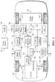
- FIG. 2is a diagram of a possible battery pack arrangement comprised of multiple cells, and monitored and controlled by a Battery Control Module.
- FIG. 3is a diagram of an example battery cell equivalent circuit.
- FIG. 4is a graph that illustrates a possible open-circuit voltage (Voc) vs. battery state of charge (SOC) relationship for a typical battery cell.
- Vocopen-circuit voltage
- SOCbattery state of charge
- FIG. 5is a graph showing a possible charge current request for facilitating battery parameter estimation.
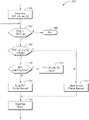
- FIG. 6is a flowchart of a possible sequence of operations for managing a charge current request.
- a battery packmay be modeled by an equivalent circuit model (ECM) having an arrangement of impedance components.
- ECMequivalent circuit model
- the ECMmay depend on the type and chemistry of the battery being used.
- the battery power capabilitymay be calculated based on the battery impedance component values of the model.
- the battery impedance component valuesmay vary with age and temperature of the battery.
- a recursive parameter estimation methodsuch as an Extended Kalman Filter (EKF) may be used to identify battery equivalent circuit model impedance parameters.
- EKFExtended Kalman Filter
- a shortcoming of the EKFis that it may require some time to converge to the true parameter values.
- the EKFmay require sufficiently dynamic inputs in order to guarantee convergence to the actual parameter values. In the absence of sufficiently dynamic inputs, the EKF may return inaccurate values.
- alternative strategiesmay be defined for updating the parameters and corresponding battery power capability values.
- FIG. 1depicts an electrified vehicle 112 that may be referred to as a plug-in hybrid-electric vehicle (PHEV).
- a plug-in hybrid-electric vehicle 112may comprise one or more electric machines 114 mechanically coupled to a gearbox or hybrid transmission 116 .
- the electric machines 114may be capable of operating as a motor and a generator.
- the hybrid transmission 116is mechanically coupled to an engine 118 .
- the hybrid transmission 116is also mechanically coupled to a drive shaft 120 that is mechanically coupled to the wheels 122 .
- the electric machines 114can provide propulsion and regenerative braking capability when the engine 118 is turned on or off.
- the electric machines 114may also act as generators and can provide fuel economy benefits by recovering energy that would normally be lost as heat in a friction braking system.
- the electric machines 114may also reduce vehicle emissions by allowing the engine 118 to operate at more efficient speeds and allowing the hybrid-electric vehicle 112 to be operated in electric mode with the engine 118 off under certain conditions.
- An electrified vehicle 112may also be a battery electric vehicle (BEV). In a BEV configuration, the engine 118 may not be present.
- a battery pack or traction battery 124stores energy that can be used by the electric machines 114 .
- the traction battery 124may provide a high voltage direct current (DC) output.
- a contactor module 142may include one or more contactors configured to isolate the traction battery 124 from a high-voltage bus 152 when opened and connect the traction battery 124 to the high-voltage bus 152 when closed.
- the high-voltage bus 152may include power and return conductors for carrying current over the high-voltage bus 152 .
- the contactor module 142may be located in the traction battery 124 .
- One or more power electronics modules 126also known as an inverter
- the power electronics modules 126are also electrically coupled to the electric machines 114 and provide the ability to bi-directionally transfer energy between the traction battery 124 and the electric machines 114 .
- a traction battery 124may provide a DC voltage while the electric machines 114 may operate with a three-phase alternating current (AC) to function.
- the power electronics module 126may convert the DC voltage to a three-phase AC current to operate the electric machines 114 .
- the power electronics module 126may convert the three-phase AC current from the electric machines 114 acting as generators to the DC voltage compatible with the traction battery 124 .
- the traction battery 124may provide energy for other vehicle electrical systems.
- the vehicle 112may include a DC/DC converter module 128 that converts the high voltage DC output from the high-voltage bus 152 to a low-voltage DC level of a low-voltage bus 154 that is compatible with low-voltage loads 156 .
- An output of the DC/DC converter module 128may be electrically coupled to an auxiliary battery 130 (e.g., 12V battery) for charging the auxiliary battery 130 .
- the low-voltage loads 156may be electrically coupled to the auxiliary battery 130 via the low-voltage bus 154 .
- One or more high-voltage electrical loads 146may be coupled to the high-voltage bus 152 .
- the high-voltage electrical loads 146may have an associated controller that operates and controls the high-voltage electrical loads 146 when appropriate. Examples of high-voltage electrical loads 146 may be a fan, an electric heating element and/or an air-conditioning compressor.
- the electrified vehicle 112may be configured to recharge the traction battery 124 from an external power source 136 .
- the external power source 136may be a connection to an electrical outlet.
- the external power source 136may be electrically coupled to a charge station or electric vehicle supply equipment (EVSE) 138 .
- the external power source 136may be an electrical power distribution network or grid as provided by an electric utility company.
- the EVSE 138may provide circuitry and controls to regulate and manage the transfer of energy between the power source 136 and the vehicle 112 .
- the external power source 136may provide DC or AC electric power to the EVSE 138 .
- the EVSE 138may have a charge connector 140 for coupling to a charge port 134 of the vehicle 112 .
- the charge port 134may be any type of port configured to transfer power from the EVSE 138 to the vehicle 112 .
- the charge port 134may be electrically coupled to an on-board power conversion module or charger.
- the charger 132may condition the power supplied from the EVSE 138 to provide the proper voltage and current levels to the traction battery 124 and the high-voltage bus 152 .
- the charger 132may be electrically coupled to the contactor module 142 .
- the charger 132may interface with the EVSE 138 to coordinate the delivery of power to the vehicle 112 .
- the EVSE connector 140may have pins that mate with corresponding recesses of the charge port 134 .
- various components described as being electrically coupled or connectedmay transfer power using a wireless inductive coupling.
- Wheel brakes 144may be provided for braking the vehicle 112 and preventing motion of the vehicle 112 .
- the wheel brakes 144may be hydraulically actuated, electrically actuated, or some combination thereof.
- the wheel brakes 144may be a part of a brake system 150 .
- the brake system 150may include other components to operate the wheel brakes 144 .
- the brake system 150may include a controller to monitor and coordinate the brake system 150 .
- the brake system 150may monitor the brake components and control the wheel brakes 144 .
- the brake system 150may respond to driver commands and may also operate autonomously to implement features such as stability control.
- the controller of the brake system 150may implement a method of applying a requested brake force when requested by another controller or sub-function.
- the electrified vehicle 112may further include a user interface 160 .
- the user interface 160may provide a variety of display elements for communicating information to the operator.
- the user interface 160may provide a variety of input elements for receiving information from the operator.
- the user interface 160include one or more displays.
- the displaysmay be touch-screen displays.
- the user interface 160may include discrete lamps/lights.
- the lampsmay include light-emitting diodes (LED).
- the user interface 160may include switches, rotary knobs, and buttons for allowing the operator to change various settings.
- the user interface 160may include a control module that communicates via the vehicle network.
- the user interface 160may provide one or more display elements that are indicative of charging being inhibited and vehicle operation being inhibited.
- the user interface 160may also provide display elements for indicating a single contactor weld condition and a double contactor weld condition.
- the display elementsmay include discrete lamps and/or messages in a message display area.
- the vehicle networkmay include a plurality of channels for communication.
- One channel of the vehicle networkmay be a serial bus such as a Controller Area Network (CAN).
- One of the channels of the vehicle networkmay include an Ethernet network defined by Institute of Electrical and Electronics Engineers (IEEE) 802 family of standards.
- Additional channels of the vehicle networkmay include discrete connections between modules and may include power signals from the auxiliary battery 130 .
- Different signalsmay be transferred over different channels of the vehicle network. For example, video signals may be transferred over a high-speed channel (e.g., Ethernet) while control signals may be transferred over CAN or discrete signals.
- the vehicle networkmay include any hardware and software components that aid in transferring signals and data between modules.
- the vehicle networkis not shown in FIG. 1 , but it may be implied that the vehicle network may connect to any electronic modules that are present in the vehicle 112 .
- a vehicle system controller (VSC) 148may be present to coordinate the operation of the various components.
- VSCvehicle system controller
- the traction battery 124may be constructed from a variety of chemical formulations. Typical battery pack chemistries may be lead acid, nickel-metal hydride (NIMH) or Lithium-Ion. FIG. 2 shows a typical traction battery pack 124 in a simple series configuration of N battery cells 202 . Other battery packs 124 , however, may be composed of any number of individual battery cells connected in series or parallel or some combination thereof.
- a battery management systemmay have one or more controllers, such as a Battery Energy Control Module (BECM) 206 , that monitor and control the performance of the traction battery 124 .
- BECMBattery Energy Control Module
- the battery pack 124may include sensors to measure various pack level characteristics.
- the battery pack 124may include one or more pack current measurement sensors 208 , pack voltage measurement sensors 210 , and pack temperature measurement sensors 212 .
- the BECM 206may include circuitry to interface with the pack current sensors 208 , the pack voltage sensors 210 and the pack temperature sensors 212 .
- the BECM 206may have non-volatile memory such that data may be retained when the BECM 206 is in an off condition. Retained data may be available upon the next key cycle.
- the battery cell 202 level characteristicsthere may be battery cell 202 level characteristics that are measured and monitored. For example, the terminal voltage, current, and temperature of each cell 202 may be measured.
- a systemmay use one or more sensor modules 204 to measure the battery cell 202 characteristics. Depending on the capabilities, the sensor modules 204 may measure the characteristics of one or multiple of the battery cells 202 .
- the battery pack 124may utilize up to N, sensor modules 204 to measure the characteristics of all the battery cells 202 .
- Each of the sensor modules 204may transfer the measurements to the BECM 206 for further processing and coordination.
- the sensor modules 204may transfer signals in analog or digital form to the BECM 206 . In some configurations, the functionality of the sensor modules 204 may be incorporated internally to the BECM 206 .
- the hardware of the sensor modules 204may be integrated as part of the circuitry in the BECM 206 and the BECM 206 may handle the processing of raw signals.
- the BECM 206may also include circuitry to interface with the contactor module 142 for opening and closing the associated contactors.
- FIG. 3shows one possible battery cell equivalent circuit model (ECM) 300 .
- a battery cellcan be modeled as a voltage source (V oc ) 350 having resistances ( 352 and 354 ) and capacitance 356 associated with it. Because of the battery cell impedance, the terminal voltage, V t 358 , is typically not the same as the open-circuit voltage, V oc 350 .
- the open-circuit voltage, V oc 350is not readily measurable as only the terminal voltage 358 of the battery cell is accessible for measurement. Because the V oc 350 is not readily measurable, a model-based method may be used to estimate the value.
- a modelmay require that the values of resistance and capacitance be known or estimated.
- the battery cell modelmay depend on the battery chemistry. The precise model chosen for the battery cell is not necessarily critical to the methods described.
- the battery cell modelmay be extended to the entire traction battery 124 comprising battery cells 202 that are electrically coupled together. For example, the various model parameters may have values based on the series/parallel combinations of the various model elements.
- FIG. 4shows a typical curve 396 showing the open-circuit voltage V oc as a function of SOC.
- the relationship between SOC and V ocmay be determined from an analysis of battery properties or from testing the battery cells.
- the functionmay be such that SOC may be calculated as f ⁇ 1 (V oc ).
- the function or the inverse functionmay be implemented as a table lookup or an equivalent equation.
- the exact shape of the curve 396may vary based on the exact formulation of the Lithium-Ion battery.
- the voltage V occhanges as a result of charging and discharging of the battery.
- the characteristicmay be used to estimate the open-circuit voltage value for the following algorithms.
- V . 2- 1 r 2 ⁇ C ⁇ V 2 + 1 C ⁇ I ( 1 )
- V oc - V tV 2 + Ir 1 ( 2 )
- V 2 360is a voltage across the RC network (C 356 /r 2 354 ) of the circuit model
- V . 2dV 2 dt is the time based derivative of V 2 360 ; r 2 354 is a charge transfer resistance of the battery; C 360 is a double layer capacitance of the battery; I 364 is the measured current flowing through the battery; V oc 350 is the open circuit voltage of the battery; V t 358 is the measured battery voltage across the battery terminals (terminal voltage); and r 1 352 is an internal resistance of the battery.
- a battery impedance parameter estimation modelmay be used to calculate the impedance parameters of the battery.
- One method of estimating the parameters of a systemis to utilize a recursive parameter estimation method, such as an Extended Kalman Filter (EKF).
- EKFExtended Kalman Filter
- an EKFmay be constructed that uses the current I 364 as an input, the voltage V 2 360 as a state, and a voltage difference, V oc ⁇ V t , as an output.
- the battery ECM impedance parameters(r 1 352 , r 2 354 , and C 356 ) or combinations of the parameters may also be treated as states for identification. Once the parameters and states have been identified, a battery power capability may be calculated based on the operating limits of a battery voltage and current, and the current battery state.
- the vehiclemay include a controller programmed to identify the parameters of the battery using a parameter estimation algorithm.
- the parametersmay include the ECM impedance and voltage parameters.
- the states of the estimation modelmay be chosen to allow one or more of the battery impedances and voltage states to be calculated either directly or indirectly.
- One such set of states for the battery modelcan be defined as follows:
- an observermay be designed to estimate the extended states (x 1 , x 2 , x 3 and x 4 ).
- the battery impedance parameters (r 1 , r 2 , and C) and the voltage parameter (V 2 )may be estimated according to the following equations.
- V ⁇ 2x 1 ( 7 )
- r ⁇ 1x 4 ( 8 )
- r ⁇ 2x 3 x 2 ( 9 )
- C ⁇1 x 3 ( 10 )
- ⁇ ( )is a system function, having k as a time index and T s is the sampling period, and defined as;
- x ⁇ ( k )[ x 1 ⁇ ( k ) x 2 ⁇ ( k ) x 3 ⁇ ( k ) x 4 ⁇ ( k ) ] ( 15 )
- i(k)is the input (e.g., battery current, I);
- w(k)is a zero mean white process noise with known covariance matrix Q(k);
- y(k)is the system output (V oc ⁇ V t );
- v(k)is a zero mean white measurement noise with known covariance matrix, R(k);
- the discrete-time domain model defined by the equationsis a nonlinear system.
- H ⁇ ( k )⁇ h ⁇ x ⁇
- x ⁇ ( k ) , i ⁇ ( k ) ,may be defined.
- the Jacobians of the system function and the measurement functionmay be derived as:
- k),may represent an a posteriori state estimate of the states x(k) at a time step k given measurements up to and including time k (e.g., y(k), y(k ⁇ 1), . . . ).
- k ⁇ 1)may represent an a priori state estimate (or prediction) of x(k) by using ⁇ circumflex over (x) ⁇ (k ⁇ 1
- k)may represent an a posterior estimation error covariance matrix for x(k) given measurements up to and including time k (e.g., y(k), y(k ⁇ 1), . . . ).
- k)may be a measure of the estimation accuracy of the state estimate.
- k)cov(x(k) ⁇ circumflex over (x) ⁇ (k
- k))may define the error covariance matrix.
- k ⁇ 1)may represent the state prediction error covariance matrix of x(k) given prior measurements (e.g., y(k ⁇ 1), y(k ⁇ 2), . . . ).
- the controllermay be programmed to execute a parameter estimation model to estimate impedance and voltage parameters of the battery.
- the operationsmay be implemented in a controller such as the BECM 206 .
- the recursive processing of the extended Kalman filtermay be executed at predefined sampling intervals.
- the parameters and variables for the state estimationmay be initialized to predetermined values. For example, ⁇ circumflex over (x) ⁇ (k ⁇ 1
- new informationmay be generated by measuring or computing corresponding parameters. Previously known or generated values may be collected and/or computed. At each time step k, values of ⁇ circumflex over (x) ⁇ (k ⁇ 1
- the system and measurement matricesmay then be updated.
- the state transition matrix, F(k)may be updated using the previous state estimate, ⁇ circumflex over (x) ⁇ (k ⁇ 1
- the measurement matrix, H(k)may be updated using the present current measurement, i(k), in the above-described equations.
- the states and the outputsmay then be predicted or learned.
- the controllermay be programmed to generate a prediction of the (a priori) state estimate as: ⁇ circumflex over (x) ⁇ ( k
- k ⁇ 1)⁇ ( ⁇ circumflex over (x) ⁇ ( k ⁇ 1
- the controllermay then be programmed to generate a prediction of the (a priori) measurement estimate: ⁇ ( k
- k ⁇ 1)h ( ⁇ circumflex over (x) ⁇ ( k
- a measurement residualmay then be generated.
- a Kalman gain, K(k)may be calculated by first predicting an (a priori) state estimate covariance as follows: P ( k
- k ⁇ 1)F ( k ⁇ 1) P ( k ⁇ 1
- the state estimation and the state estimation covariancemay then be computed.
- the controllermay be programmed to update the (a posteriori) state estimate as follows: ⁇ circumflex over (x) ⁇ ( k
- k )⁇ circumflex over (x) ⁇ ( k
- the (a posteriori) state estimate covariancemay be updated according to following equation: P ( k
- k )( I ⁇ K ( k ) H ( k )) P ( k
- k )( I ⁇ K ( k ) H ( k )) P ( k
- the ECM parametersmay be derived from the state estimates as follows:
- V ⁇ 2 ⁇ ( k )x ⁇ 1 ⁇ ( k ⁇
- r ⁇ 1 ⁇ ( k )x ⁇ 4 ⁇ ( k ⁇
- r ⁇ 2 ⁇ ( k )x ⁇ 3 ⁇ ( k ⁇
- c ⁇ ⁇ ( k )1 x ⁇ 3 ⁇ ( k ⁇
- the battery power capabilitymay be calculated based on the estimated ECM parameters as will be described herein.
- Several battery power capability parametersmay be defined.
- An allowed minimum pack voltage, v minmay be defined that may change with battery temperature.
- An allowed maximum pack voltage, v maxmay be defined that may change with battery temperature.
- the minimum pack voltage and the maximum pack voltagemay be defined by the manufacturer based on the battery characteristics.
- a discharge current limit, i dchlimmay be defined that changes with battery temperature and SOC.
- a charge current limit, i chlimmay be defined that changes with battery temperature and SOC.
- the battery power capability parametersmay be computed for different time intervals.
- a time duration, t dmay be defined for the power capability estimates.
- the time durationmay be indicative of the time over which the power capability is rated.
- a one-second power capability estimationmay be defined by setting the time duration to one second and a half-second power capability estimation may be defined by setting the time duration to a half second.
- the power capabilitymay describe the amount of power that may be provided to or from the battery during the time duration.
- the first order differential equations described abovemay be solved using the estimated battery ECM parameters in the equations to yield the following expression for the battery current (I).
- the battery power capabilitycan be estimated.
- the current equationcan be solved for a minimum value of current (I), such as described in the following equation.
- currentis defined as a positive (+) quantity when flowing away from a battery (discharge), and as a negative ( ⁇ ) quantity when flowing into the battery (charge).
- I ⁇ ( t d , v max )V oc - V max - V ⁇ 2 ⁇ ( 0 ) ⁇ e - t d / ( r ⁇ 2 ⁇ C ⁇ ) [ r ⁇ 1 + r ⁇ 2 ( 1 - e - t d / ( r ⁇ 2 ⁇ C ⁇ ) ] ( 34 )
- the value of (t d )is the predetermined time duration, and may be for example, between 0.5 sec. and 10 sec.
- V maxis a maximum operating voltage for the battery, and may be considered a limiting battery voltage.
- the charge power capabilitymay be defined as:
- the time value (t d )can be based on how the battery power capabilities are used by vehicle system controller.
- the maximum voltage (v max )may be determined, for example, by a vehicle manufacturer or a battery manufacturer as the maximum voltage that the battery is allowed to attain.
- a method for determining a discharge power capability for the batterymay also be provided.
- a maximum value of the battery current (I)may be used in conjunction with a minimum value of the battery voltage.
- the current equation described abovecan be used to solve for I max as:
- I ⁇ ( t d , v min )( V oc - V min - V ⁇ 2 ⁇ ( 0 ) ⁇ e - t d / ( r ⁇ 2 ⁇ C ⁇ ) ) [ r ⁇ 1 + r ⁇ 2 ( 1 - e - t d / ( r ⁇ 2 ⁇ C ⁇ ) ] ( 37 )
- v minis a minimum operating voltage of the battery pack.
- the discharge power capabilitymay be defined as:
- P cap_dch⁇ i max ⁇ ⁇ ⁇ V oc - V ⁇ 2 ⁇ ( 0 ) ⁇ e - t d r ⁇ 2 ⁇ C ⁇ - i max * [ r ⁇ 1 + r ⁇ 2 ( 1 - e - t d r ⁇ 2 ⁇ C ⁇ ) ] ⁇ ( 39 )
- the battery power capabilityis based on the battery ECM impedance parameters (e.g., r 1 , r 2 and C) that are estimated by the EKF.
- the battery power capabilityis further based on the ECM voltage parameter (V 2 ) that is estimated by the model. Note that other calculation methods for the battery power capability may be possible.
- the above calculation schemeis merely representative of using a battery impedance parameter estimation model to calculate battery power capability.
- Other battery parametersmay be derived from the ECM impedance parameters as well.
- the battery and electrical loadsmay be operated based on the calculated battery power capability. That is, battery current and voltage may be maintained so as not to exceed the battery power capability. Battery power during charging and discharging may be defined as the product of the voltage across the battery terminals and the current flowing through the battery. Electrical loads receiving power from or providing power to the battery may be operated such that the total power of all loads falls within the calculated battery power capability. For example, electric machines may have power limits reduced so that the battery power capability is not exceeded. The controller may manage the electrical loads to maintain the battery power within the computed limits.
- the above description thus fardescribes an example of using an EKF to estimate the states and impedance parameters of a battery ECM.
- the impedance parametersare a function of the ECM that is chosen.
- the methods described beloware applicable to other battery circuit model formulations as well.
- the statesmay be defined differently having more or less states or parameters to estimate.
- the battery power capability estimatemay be adjusted to correspond to the particular formulation used.
- the battery power capabilityis a useful quantity for effectively controlling the powertrain.
- the above descriptionis one example of using an Extended Kalman Filter (EKF) to identify battery equivalent circuit model impedance parameters and calculating the related battery power capabilities from the battery impedance parameters.
- the EKFmay require some time to converge to the true parameter values.
- the convergence timemay be a function of the starting values that are used to initialize the EKF.
- the convergence of the EKFmay be influenced by an efficient choice of the initial parameter values.
- the capacity, power and energymay decay or decrease.
- decayed power capability of the batterycan be estimated online by using, for example, the EKF framework based on the battery equivalent circuit model.
- the resistances and capacitancewill change with battery age, temperature, and SOC. As such, it may be useful to periodically estimate the parameters to adjust the control strategies.
- the ECM impedance parametersmay change over a large range with temperature. For example, for the same SOC and discharge current, battery terminal voltage may be much lower at low temperatures than at room temperature because r 1 at low temperature is typically greater than that at room temperature. This results in decrease in the discharge power capability at low temperature when compared with the discharge power capability at room temperature. Correctly adjusting the battery parameters to compensate for this can ensure that the battery is operated within the proper limits.
- persistent excitation conditionsmay be defined to achieve an accurate online identification for the ECM parameters and, consequently, an accurate model-based battery power capability estimation.
- Persistent excitationmay be achieved by the battery current being dynamic or sufficiently variable.
- the currentmay not be considered to be sufficiently dynamic when the current is generally constant or slowly changing.
- a generally constant currentmay be defined as a current that remains within a small range of current values for a time interval greater than a predetermined time.
- the BECM 206may monitor conditions for persistent excitation and only execute the EKF parameter estimation when sufficiently dynamic conditions are present.
- the parameter estimationmay be inhibited during conditions of constant current.
- the chargingis often performed at a constant current level.
- conditions for performing the parameter estimationmay not normally be present.
- a charge eventmay be initiated by coupling the EVSE connector 140 to the charge port 134 .
- the BECM 206may be programmed to communicate with the EVSE 138 to manage the charging operation. For example, the BECM 206 may generate a charge current request to define the current for charging the traction battery 124 . The charge current request may be used by the EVSE 138 and/or power conversion module 132 to control the current flowing to the traction battery 124 to the charge current request.
- the BECM 206may monitor the state of the traction battery 124 to determine the charge current request. For example, the BECM 206 may compute and monitor the state of charge of the traction battery 124 .
- the BECM 206may generate a charge current request that is a generally constant current.
- the generally constant currentmay be selected based on a desired charge power level.
- the normal charge eventmay include a duration of constant current charging.
- the normal charge eventmay include a duration of constant voltage charging. For example, as the traction battery 124 state of charge increases, charging voltage limits may be reached.
- the battery currentmay decrease.
- the currentis generally constant or slowly varying. As such, the current during the normal charge event may not be sufficiently dynamic for parameter identification.
- the BECM 206may be programmed to identify conditions in which to perform the parameter estimation strategy to identify the parameters of the traction battery 124 .
- the BECM 206may monitor the time intervals between parameter estimations. This may be monitored by storing a time value corresponding to the most recent successful parameter estimation. A current time value may be compared to the stored time value. If a difference between the current time value and the stored time value (e.g., elapsed time since last parameter estimation) exceeds a predetermined time interval, the BECM 206 may generate a parameter estimation request.
- the predetermined time intervalmay be a calibratable value.
- the BECM 206may be programmed to monitor a battery current throughput since the last parameter estimation.
- the battery throughputmay be defined as the time integral of the battery current over a time interval.
- a battery throughput variablemay be initialized to zero upon successful completion of a parameter estimation cycle.
- the battery currentmay be sampled and an integral of the battery current may be computed.
- the product of the battery current and the sampling time intervalmay be added to the battery throughput variable.
- the battery throughput variablemay be compared to a predetermined battery throughput value. If the battery throughput variable exceeds the predetermined battery throughput value, the BECM 206 may generate a parameter estimation request.
- the above strategies for generating the parameter estimation requestmay take place over one or more ignition cycles.
- the associated variablesmay be stored in non-volatile memory to allow the time and/or throughput to accumulate over multiple ignition or power-on cycles. For example, the battery throughput may be accumulated over multiple ignition cycles.
- the BECM 206may be programmed to create conditions to achieve persistent excitation for the parameter estimation during the charge event. Disclosed herein is a strategy of achieving persistent excitation for improving convergence and accuracy of the EKF parameter estimation during plug-in charging events.
- the BECM 206may cause the charge current request to vary during charging to achieve a sufficiently dynamic current input for the EKF estimation strategy.
- a maximum charging current request(chrg_I_req_Max) may be defined based on characteristics of the charging station, charger, and/or battery cells. The maximum charging current request may define the maximum amount of charge current that can be flowed to the traction battery 124 .
- a minimum charging current request(chrg_I_req_Min) may be defined based on charger limitations. The minimum charging current may define the minimum current that should flow during charging. The maximum charging current request may be greater than the minimum charging current request. The minimum charging current request may be greater than or equal to zero.
- a charging current request slew rate(chrg_I_req_slew) may be defined that defines a maximum rate of change of the current request.
- the charging current request slew ratemay be based on utility considerations to avoid potential flickering issues due to sudden large loads being added to the power grid. For example, the charging current request may be allowed to change at a rate of one Amp/second.
- a charging current request(chrg_I_req) may be defined that is the requested charge current.
- the charging current requestmay be the current requested during the normal charging cycle.
- the charging current requestmay be constrained by the maximum charging current request, the minimum charging current request, and the charging current request slew rate.
- the charging current requestmay be a generally constant current or slowly changing current.
- An EKF charging current request(charg_I_req_ekf) may be defined that is the requested charge current for EKF parameter estimation.
- the EKF charging current requestmay be constrained by the maximum charging current request, the minimum charging current request, and the charging current request slew rate.
- the EKF charging current requestmay be configured to vary the battery current to achieve a persistently exciting input that is sufficient for parameter estimation.
- the charging current requestmay be used to define the level of charge current.
- the charging current requestmay be configured to minimize the charge time.
- the charging current requestmay be at a generally constant level.
- the normal current requestmay not cause a sufficiently dynamic current for parameter estimation purposes.
- the controllermay apply the EKF charging current request during the charge cycle. While the EKF charging current request is applied, the EKF parameter estimation strategy may be performed as detailed above. Once the EKF parameter estimation has converged to a solution, the BECM 206 may apply the normal charging current request. The benefit of this strategy is that the battery parameters can be estimated during the charge cycle within little disruption to the normal charging process.
- the EKF charging current requestmay be defined as:
- chrg_I ⁇ _req ⁇ _ekf ⁇ ( t )chrg_I ⁇ _req ⁇ _min + chrg_I ⁇ _req ⁇ _max - chrg_I ⁇ _req ⁇ _min 2 + chrg_I ⁇ _req ⁇ _max - chrg_I ⁇ _req ⁇ _min 2 ⁇ sin ( ⁇ * chrg_I ⁇ _req ⁇ _slew chrg_I ⁇ _req ⁇ _max - chrg_I ⁇ _req ⁇ _min t ) ( 40 )
- FIG. 5depicts an example graph 500 of the EKF charging current request.
- the graph 500depicts an EKF charging current request curve 502 generated by the above equation.
- the maximum charge currentis set to 10 A
- the minimum charge currentis set to 1 A
- the slew rateis set to 1 A/sec.
- the equationdefines a sinusoidal charging current request that oscillates between the maximum and minimum charge requests.
- the EKF charging current requestthat oscillates about an average of the minimum and maximum charge current values.
- the EKF charging current requestas defined periodically drives the current between the maximum and minimum limits to ensure a dynamic current for parameter estimation.
- the frequency of the EKF charging current requestmay depend on the above-defined slew rate parameter.
- the frequency of the EKF charging current requestmay be configured such that a rate of change of the current flowing to the battery is prevented from exceeding a predetermined maximum rate of change.
- the EKF charging current requestmay be a sinusoidal current that varies sinusoidally between a predetermined maximum current and a predetermined minimum current.
- EKF charging current request definitionsare possible. While the above example is generated by an equation, other methods of generating the waveform are possible. For example, a sufficiently dynamic current waveform may be defined by testing or analysis. The waveform may be stored in memory and applied during runtime when the estimation is activated. In other examples, the frequency of the sinusoidal EKF charging current request may be changed over the parameter estimation cycle. In other examples, the amplitude of the sinusoidal EKF charging current request may be changed over the parameter estimation cycle.
- FIG. 6depicts a flow chart 600 of a possible sequence of operations for implementing the parameter estimation strategy detailed herein.
- the systemmay determine if the EKF parameter estimation should be performed.
- the controllermay check conditions such as the amount of time that has elapsed since the last parameter estimation or if the battery throughput has exceeded a predetermined threshold since the last parameter estimation.
- the controllermay update the status of a request parameter estimation flag (EKF_run_req_flg). If the parameter estimation conditions are satisfied, the request parameter estimation flag may be set to TRUE.
- a checkmay be performed to determine if plug-in charging is active or available. For example, the controller may check to see if a charge connector is coupled to the charge port. The controller may check to determine if communication is established with the EVSE 138 . If plug-in charging is not active, execution proceeds to operation 606 which ends the procedure. Operations starting at operation 602 may be repeated at a later time. If plug-in charging is active, operation 608 may be performed.
- the status of the request parameter estimation flagmay be checked. If the request parameter estimation flag is FALSE, no parameter estimation is performed and operation 614 may be performed. At operation 614 , the normal charging current request is applied. That is, the battery will be charged using the normal charging current request.
- the normal charging current requestmay be a generally constant current.
- operation 610may be performed.
- a checkis performed to determine if the EKF parameter estimation is completed.
- EKF parameter estimationmay be completed responsive to a magnitude of the residual or error becoming less than a predetermined error (e.g., a small value near zero). In other case, the EKF may be deemed completed upon expiration of a predetermined amount of time.
- operation 612may be performed.
- the request parameter estimation flagmay be set to FALSE to return to normal operation.
- operation 614may be performed to apply the normal charging current request.
- the EKF parameter estimationmay be performed by a separate control logic running at a different rate than the charge request current determination.
- operation 616may be performed.
- the EKF charging current requestis applied.
- the EKF charging current requestmay be applied as described above and may generate a continuously varying current that provides a persistent excitation for the parameter estimation algorithm.
- the persistent excitation conditionmay be a current that causes a residual error of the parameter estimation algorithm to converge toward zero.
- the parameter estimation algorithmmay run in parallel to the charge current determination strategy.
- the requested charge currentmay be limited to the slew rate to ensure that any changes in the requested current are within the slew rate limits.
- the controllermay be programmed to identify values of parameters of the battery via a parameter estimation algorithm as described above.
- the controllermay be programmed to, responsive to an external power supply being coupled to the vehicle and providing a current to the traction battery in a presence of a request to identify the parameters of the traction battery, change the current flowing to the battery from a normal charging current to a predetermined charge current that causes a persistent excitation condition to be satisfied for the parameter estimation strategy.
- the controllermay be further programmed to, responsive to identifying the battery parameters with a predetermined accuracy, change the current to the normal charging current for charging the battery.
- a system for charging a battery of a vehicleincludes a controller programmed to, responsive to an external power source providing power to the battery during a charge event and in a presence of a request to identify parameters of the battery using a parameter estimation algorithm, change a current flowing to the battery from a generally constant current to a predetermined varying charge current that causes a persistent excitation condition to be satisfied for the parameter estimation algorithm.
- the disclosed procedureimproves vehicle performance by creating conditions for accurate parameter estimation during charging. As a result, battery parameters and dependent values to be more accurate which allows for improved control and notification of battery-related features. Battery charging is minimally affected since the parameter estimation can typically complete in several minutes. Additionally, the operator is unlikely to notice that the parameter estimation was performed.
- the processes, methods, or algorithms disclosed hereincan be deliverable to/implemented by a processing device, controller, or computer, which can include any existing programmable electronic control unit or dedicated electronic control unit.
- the processes, methods, or algorithmscan be stored as data and instructions executable by a controller or computer in many forms including, but not limited to, information permanently stored on non-writable storage media such as ROM devices and information alterably stored on writeable storage media such as floppy disks, magnetic tapes, CDs, RAM devices, and other magnetic and optical media.
- the processes, methods, or algorithmscan also be implemented in a software executable object.
- the processes, methods, or algorithmscan be embodied in whole or in part using suitable hardware components, such as Application Specific Integrated Circuits (ASICs), Field-Programmable Gate Arrays (FPGAs), state machines, controllers or other hardware components or devices, or a combination of hardware, software and firmware components.
- suitable hardware componentssuch as Application Specific Integrated Circuits (ASICs), Field-Programmable Gate Arrays (FPGAs), state machines, controllers or other hardware components or devices, or a combination of hardware, software and firmware components.
- These attributesmay include, but are not limited to cost, strength, durability, life cycle cost, marketability, appearance, packaging, size, serviceability, weight, manufacturability, ease of assembly, etc. As such, embodiments described as less desirable than other embodiments or prior art implementations with respect to one or more characteristics are not outside the scope of the disclosure and can be desirable for particular applications.
Landscapes
- Engineering & Computer Science (AREA)
- Power Engineering (AREA)
- Transportation (AREA)
- Mechanical Engineering (AREA)
- Life Sciences & Earth Sciences (AREA)
- Sustainable Development (AREA)
- Sustainable Energy (AREA)
- Secondary Cells (AREA)
- Electric Propulsion And Braking For Vehicles (AREA)
Abstract
Description
where:
is the time based derivative of
The system output may be defined as:
y=Voc−V1 (4)
The system output may be estimated using the measured terminal voltage and the open-circuit voltage derived from the state of charge. Equations (1) and (2) may be written in terms of the defined states as follows:
{dot over (x)}1=−x1x2+x3I (5)
y=x1+x4I (6)
x(k)=ƒ(x(k−1),i(i−1))+w(k−1) (11)
y(k)=h(x(k),i(k))+v(k) (12)
where
h(x(k),i(k))=x1(k)+x4(k)i(k) (14)
x(k) is the system state x that is evaluated at a time k*Tsas;
and an observation model,
may be defined. To linearize the equations, the Jacobians of the system function and the measurement function may be derived as:
x(k)=F(k)×(k−1)+w(k−1) (18)
y(k)=H(k)×(k)+v(k) (19)
{circumflex over (x)}(k|k−1)=ƒ({circumflex over (x)}(k−1|k−1),i(k)) (20)
The controller may then be programmed to generate a prediction of the (a priori) measurement estimate:
ŷ(k|k−1)=h({circumflex over (x)}(k|k−1),i(k)) (21)
e(k)=y(k)−ŷ(k|k−1) (22)
P(k|k−1)=F(k−1)P(k−1|k−1)F(k−1)′+Q(k−1) (23)
A measurement residual (or innovation) covariance S(k)=cov(e(k)) may be generated as follows:
S(k)=H(k)P(k|k−1)H(k)′+R(k) (24)
The Kalman gain may then be computed as:
K(k)=P(k|k−1)H(k)′S(k)−1 (25)
{circumflex over (x)}(k|k)={circumflex over (x)}(k|k−1)+K(k)e(k) (26)
where K(k) is the Kalman gain. The (a posteriori) state estimate covariance may be updated according to following equation:
P(k|k)=(I−K(k)H(k))P(k|k−1)(I−K(k)H(k))′+K(k)R(k)K(k)′ (27)
and may be equivalently be expressed as:
P(k|k)=(I−K(k)H(k))P(k|k−1) (28)
where: tdis the predetermined time duration; {circumflex over (V)}2(0) is the present value of V2, and e is the base of the natural logarithm.
where: the value of (td) is the predetermined time duration, and may be for example, between 0.5 sec. and 10 sec., and Vmaxis a maximum operating voltage for the battery, and may be considered a limiting battery voltage.
imin=max(I(td,vmax),ichlim) (35)
The charge power capability may be defined as:
where: vminis a minimum operating voltage of the battery pack.
imax=min(I(td,vmin),idchhlim) (38)
The discharge power capability may be defined as:
Claims (18)
Priority Applications (3)
| Application Number | Priority Date | Filing Date | Title |
|---|---|---|---|
| US16/735,330US11498446B2 (en) | 2020-01-06 | 2020-01-06 | Plug-in charge current management for battery model-based online learning |
| DE102020134778.2ADE102020134778A1 (en) | 2020-01-06 | 2020-12-22 | PLUG-IN CHARGING CURRENT MANAGEMENT FOR BATTERY MODEL BASED ONLINE LEARNING |
| CN202011535759.1ACN113071367A (en) | 2020-01-06 | 2020-12-23 | Plug-in charging current management for online learning based on battery model |
Applications Claiming Priority (1)
| Application Number | Priority Date | Filing Date | Title |
|---|---|---|---|
| US16/735,330US11498446B2 (en) | 2020-01-06 | 2020-01-06 | Plug-in charge current management for battery model-based online learning |
Publications (2)
| Publication Number | Publication Date |
|---|---|
| US20210206291A1 US20210206291A1 (en) | 2021-07-08 |
| US11498446B2true US11498446B2 (en) | 2022-11-15 |
Family
ID=76432434
Family Applications (1)
| Application Number | Title | Priority Date | Filing Date |
|---|---|---|---|
| US16/735,330Active2040-10-07US11498446B2 (en) | 2020-01-06 | 2020-01-06 | Plug-in charge current management for battery model-based online learning |
Country Status (3)
| Country | Link |
|---|---|
| US (1) | US11498446B2 (en) |
| CN (1) | CN113071367A (en) |
| DE (1) | DE102020134778A1 (en) |
Families Citing this family (4)
| Publication number | Priority date | Publication date | Assignee | Title |
|---|---|---|---|---|
| DE102019129799A1 (en)* | 2019-11-05 | 2021-05-06 | Lisa Dräxlmaier GmbH | METHOD AND DEVICE FOR CHARGING AN ELECTRICALLY POWERED VEHICLE |
| US20230093677A1 (en)* | 2021-09-22 | 2023-03-23 | Apple Inc. | Battery power capability prediction and correction |
| EP4257415A1 (en)* | 2022-04-08 | 2023-10-11 | Scania CV AB | Control device and method for controlling charging of an energy storage device |
| CN115728583B (en)* | 2022-11-16 | 2025-02-11 | 公牛集团股份有限公司 | Method and system for detecting the state of a charging system of an electric vehicle |
Citations (122)
| Publication number | Priority date | Publication date | Assignee | Title |
|---|---|---|---|---|
| US4069449A (en)* | 1976-02-03 | 1978-01-17 | Hughes Aircraft Company | Flyback type power supply |
| JPH03226688A (en)* | 1990-01-31 | 1991-10-07 | Yuasa Battery Co Ltd | Method for judging life of lead storage battery |
| JPH03249582A (en)* | 1990-02-27 | 1991-11-07 | Yuasa Corp | Method for deciding life of lead battery |
| US5149413A (en)* | 1990-08-06 | 1992-09-22 | Maget Henri J R | Efficient electrochemical motor |
| US5193067A (en)* | 1988-12-05 | 1993-03-09 | Nippondenso Co., Ltd. | Battery condition detecton apparatus |
| JPH06276744A (en)* | 1993-03-20 | 1994-09-30 | Victor Co Of Japan Ltd | Power supply device |
| US5537021A (en)* | 1991-09-27 | 1996-07-16 | Alcatel Bell-Sdt S.A. | Low-loss resonant circuit for capacitance driver |
| US5631542A (en)* | 1994-06-16 | 1997-05-20 | Robert Bosch Gmbh | Method for controlling the strength of a charging current |
| US6061638A (en)* | 1997-07-30 | 2000-05-09 | Auto Meter Products, Inc. | Microprocessor-based battery tester system |
| US6075350A (en)* | 1998-04-24 | 2000-06-13 | Lockheed Martin Energy Research Corporation | Power line conditioner using cascade multilevel inverters for voltage regulation, reactive power correction, and harmonic filtering |
| US6130522A (en)* | 1998-07-27 | 2000-10-10 | Makar; Dominique G. | Pulse modified invariant current battery charging method and apparatus |
| US6137280A (en)* | 1999-01-22 | 2000-10-24 | Science Applications International Corporation | Universal power manager with variable buck/boost converter |
| US6232746B1 (en)* | 1999-07-05 | 2001-05-15 | Yazaki Corporation | Battery charging apparatus and full-charging detecting method |
| US20010028238A1 (en)* | 1998-08-10 | 2001-10-11 | Kenji Nakamura | Method and device for judging the condition of secondary batteries and method for regenerating secondary batteries |
| US20020196027A1 (en)* | 2001-06-26 | 2002-12-26 | Tate Edward Dean | State-of-charge detection device for a battery |
| US20030162088A1 (en)* | 2000-08-09 | 2003-08-28 | Makoto Nakanishi | Coin-shaped battery |
| US20040085072A1 (en)* | 2002-11-05 | 2004-05-06 | The Furukawa Battery Co., Ltd. | Method and system for monitoring state of lead acid battery |
| US20040128088A1 (en)* | 1996-03-27 | 2004-07-01 | Laletin William H. | Method of analyzing the time-varying electrical response of a stimulated target substance |
| US20040169495A1 (en)* | 2003-02-28 | 2004-09-02 | Nissan Motor Co., Ltd. | Estimating apparatus and method of input and output enabling powers for secondary cell |
| KR100454645B1 (en)* | 1999-01-28 | 2004-11-03 | 현대중공업 주식회사 | Output current limit control device of a supplementary power for electromotion a vehicle |
| WO2005029096A2 (en)* | 2003-09-15 | 2005-03-31 | Georgia Tech Research Corporation | System and mothod for determining harmonic contributions from non-linear loads |
| US20060000460A1 (en)* | 2003-11-26 | 2006-01-05 | Autotronic Controls Corporation | High energy ignition method and system using pre-dwell control |
| US20060152224A1 (en)* | 2003-04-23 | 2006-07-13 | Deuk-Soo Kim | Diagnosis for expected life of emergency power apparatus |
| US7164272B1 (en)* | 2000-10-13 | 2007-01-16 | Lear Automotive (Eeds) Spain, S.L. | Modular unit connectable to the battery of a vehicle for monitoring its condition and protecting the electrical system of said vehicle |
| US20070048607A1 (en)* | 2003-12-15 | 2007-03-01 | Mitsubishi Chemical Corporation | Nonaqueous-electrolyte secondary battery |
| US20070299620A1 (en)* | 2006-06-26 | 2007-12-27 | Han-Seok Yun | Method for estimating state of charge of battery, battery management system using same, and driving method thereof |
| US20080303528A1 (en)* | 2005-12-08 | 2008-12-11 | Kim Deuk Soo | Method and Device for Measuring Internal Impedance of Stationary Battery |
| US7626394B2 (en)* | 2005-09-16 | 2009-12-01 | The Furukawa Electric Co., Ltd. | Method and apparatus for determining deterioration of secondary battery, and power supply system therewith |
| US20100068628A1 (en)* | 2007-06-22 | 2010-03-18 | Tomohiro Ueda | All solid-state polymer battery |
| US20110008661A1 (en)* | 2008-03-07 | 2011-01-13 | Kiyomi Kozuki | Lithium ion secondary battery and method for producing the same |
| KR20110072838A (en)* | 2009-12-23 | 2011-06-29 | 재단법인 포항산업과학연구원 | Model Current Tracking Adaptive Control Method of Inverter |
| US20110161025A1 (en)* | 2008-09-02 | 2011-06-30 | Kabushiki Kaisha Toyota Chuo Kenkyusho | State estimating device for secondary battery |
| US20110187329A1 (en)* | 2008-09-11 | 2011-08-04 | Mitsumi Electric Co., Ltd. | Battery condition detector, battery pack including same, and battery condition detecting method |
| US20110311860A1 (en)* | 2010-06-17 | 2011-12-22 | Sony Corporation | Nonaqueous electrolyte battery and nonaqueous electrolyte |
| US20120026771A1 (en)* | 2010-08-02 | 2012-02-02 | Denso Corporation | Vehicle-use power supply control apparatus and control apparatus for controlling electric rotating machine mounted on vehicle as main engine |
| US20120105013A1 (en)* | 2010-10-29 | 2012-05-03 | Gm Global Technology Operations, Inc. | Apparatus of soc estimation during plug-in charge mode |
| US20120200266A1 (en)* | 2010-06-24 | 2012-08-09 | Fred Berkowitz | Method and Circuitry to Calculate the State of Charge of a Battery/Cell |
| WO2012159298A1 (en)* | 2011-06-27 | 2012-11-29 | 华为技术有限公司 | Method and apparatus for implementing uplink data transmission |
| US20120310567A1 (en)* | 2009-12-11 | 2012-12-06 | Holger Fink | Determining the internal resistance of a battery cell of a traction battery that is connected to a controllable motor/generator |
| US20120316815A1 (en)* | 2011-01-14 | 2012-12-13 | Kenichi Morigaki | Method for evaluating deterioration of lithium ion secondary battery, and battery pack |
| US20120328944A1 (en)* | 2009-12-24 | 2012-12-27 | Panasonic Corporation | Electrode and electricity storage device |
| US20130047721A1 (en)* | 2010-01-15 | 2013-02-28 | Hiroki Nagai | Method of evaluating positive electrode active material |
| US20130093384A1 (en)* | 2010-04-26 | 2013-04-18 | Nec Corporation | Secondary battery state management system, battery charger, secondary battery state management method, and electrical characteristics measurement method |
| US20130141109A1 (en)* | 2011-12-05 | 2013-06-06 | Corey T. Love | Battery Health Monitoring System and Method |
| US20130154577A1 (en)* | 2010-12-20 | 2013-06-20 | Furukawa Automotive Systems Inc. | Full Charge Sensing Apparatus And Full Charge Sensing Method |
| US20130179061A1 (en)* | 2010-06-10 | 2013-07-11 | The Regents Of The University Of California | Smart electric vehicle (ev) charging and grid integration apparatus and methods |
| WO2013124012A2 (en)* | 2012-02-23 | 2013-08-29 | Siemens Aktiengesellschaft | Charging device for an electrically operated vehicle |
| US20130278223A1 (en)* | 2012-04-20 | 2013-10-24 | Ford Global Technologies, Llc | Battery Controller with Monitoring Logic for Model-Based Battery Control |
| US20130307334A1 (en)* | 2012-05-18 | 2013-11-21 | Caterpillar Inc. | System for determining battery impedance |
| KR20140052658A (en)* | 2012-10-25 | 2014-05-07 | 현대모비스 주식회사 | Intelligent battery sensor and battery internal resistance estimation method thereof |
| US20140180614A1 (en)* | 2012-12-26 | 2014-06-26 | Robert Bosch Gmbh | System And Method For Selective Estimation Of Battery State With Reference To Persistence Of Excitation And Current Magnitude |
| US20140191764A1 (en)* | 2013-01-10 | 2014-07-10 | Yokogawa Electric Corporation | Method for determining response characteristics of battery |
| US20140214268A1 (en)* | 2013-01-29 | 2014-07-31 | Ford Global Technologies, Llc | Temperature compensated battery parameter estimation |
| US20140225567A1 (en)* | 2011-08-31 | 2014-08-14 | Volkswagen Ag | Method and device for charging an energy store of a vehicle |
| US20140244225A1 (en)* | 2013-02-24 | 2014-08-28 | The University Of Connecticut | Battery state of charge tracking, equivalent circuit selection and benchmarking |
| US20140266059A1 (en)* | 2013-03-14 | 2014-09-18 | Ford Global Technologies, Llc | Selective updating of battery parameter estimations |
| US20140287287A1 (en)* | 2011-10-13 | 2014-09-25 | Waseda University | Battery system and evaluation method for battery |
| US20150066407A1 (en)* | 2012-04-30 | 2015-03-05 | Lg Chem, Ltd. | Apparatus and method for estimating parameter of secondary battery |
| US20150064510A1 (en)* | 2013-08-30 | 2015-03-05 | Ford Global Technologies, Llc | Battery Power Capability Estimation at Vehicle Start |
| US20150066262A1 (en)* | 2013-08-30 | 2015-03-05 | Ford Global Technologies, Llc | In-range current sensor fault detection |
| US20150097512A1 (en)* | 2013-10-04 | 2015-04-09 | Ford Global Technologies, Llc | Vehicle battery charge setpoint control |
| EP2869075A1 (en)* | 2013-11-04 | 2015-05-06 | ABB Technology AG | System and method for detecting a leakage from power cables of a DC bus to ground |
| US20150163874A1 (en)* | 2013-12-11 | 2015-06-11 | General Electric Company | Multi-mode controller circuit |
| US20150158395A1 (en)* | 2013-12-06 | 2015-06-11 | Ford Global Technologies, Llc | Estimation and Compensation of Battery Measurement and Asynchronization Biases |
| US20150171640A1 (en)* | 2013-12-18 | 2015-06-18 | Ford Global Technologies, Llc | Battery parameter estimation |
| US20150231985A1 (en)* | 2014-02-20 | 2015-08-20 | Ford Global Technologies, Llc | State of Charge Quality Based Cell Balancing Control |
| US20150232083A1 (en)* | 2014-02-20 | 2015-08-20 | Ford Global Technologies, Llc | Active Battery Parameter Identification Using Conditional Extended Kalman Filter |
| US20150231986A1 (en)* | 2014-02-20 | 2015-08-20 | Ford Global Technologies, Llc | Battery Capacity Estimation Using State of Charge Initialization-On-The-Fly Concept |
| US20150231982A1 (en)* | 2014-02-20 | 2015-08-20 | Ford Global Technologies, Llc | Active Battery System Estimation Request Generation |
| US9132745B1 (en)* | 2014-03-17 | 2015-09-15 | Ford Global Technologies, Llc | Frequency based battery model parameter estimation |
| US20150270072A1 (en)* | 2012-08-30 | 2015-09-24 | Kureha Corporation | Carbonaceous material for negative electrodes of lithium ion capacitors and method for producing same |
| US20150288197A1 (en)* | 2013-08-30 | 2015-10-08 | Foundation Of Soongsil University-Industry Cooperation | Charger Having Battery Diagnostic Function and Control Method Thereof |
| US20150285867A1 (en)* | 2014-04-08 | 2015-10-08 | Ford Global Technologies, Llc | Model-based diagnosis for battery voltage |
| US20150306971A1 (en)* | 2014-04-29 | 2015-10-29 | Ford Global Technologies, Llc | Method to Adjust Battery Minimum State of Charge Limits Based on Battery Power Capability |
| JP2015195682A (en)* | 2014-03-31 | 2015-11-05 | パナソニックIpマネジメント株式会社 | inverter device |
| US20150326038A1 (en)* | 2014-05-09 | 2015-11-12 | Ford Global Technologies, Llc | System and method for battery power management |
| US20150352972A1 (en)* | 2014-06-09 | 2015-12-10 | Ford Global Technologies, Llc | Estimation and compensation of battery measurement |
| US20160006275A1 (en)* | 2014-07-01 | 2016-01-07 | Ford Global Technologies, Llc | System and method for battery open circuit voltage estimation |
| US20160001672A1 (en)* | 2014-07-01 | 2016-01-07 | Ford Global Technologies, Llc | Equivalent circuit based battery current limit estimations |
| US20160013716A1 (en)* | 2014-07-10 | 2016-01-14 | University-Industry Foundation(UIF) | Fault current reduction structure of multi-level converter and apparatus using the fault current reduction structure |
| US20160020618A1 (en)* | 2014-07-21 | 2016-01-21 | Ford Global Technologies, Llc | Fast Charge Algorithms for Lithium-Ion Batteries |
| US20160025789A1 (en)* | 2014-07-24 | 2016-01-28 | Ford Global Technologies, Llc | Harness anomaly detection systems and methods |
| US20160059023A1 (en)* | 2014-09-02 | 2016-03-03 | Zoll Medical Corporation | Impedance Spectroscopy for Defibrillator Applications |
| CN105425153A (en)* | 2015-11-02 | 2016-03-23 | 北京理工大学 | Method for estimating charge state of power cell of electric vehicle |
| US20160093927A1 (en)* | 2014-09-26 | 2016-03-31 | Ford Global Technologies, Llc | Battery capacity degradation resolution methods and systems |
| US9377512B2 (en)* | 2013-05-08 | 2016-06-28 | GM Global Technology Operations LLC | Battery state estimator combining electrochemical solid-state concentration model with empirical equivalent-circuit model |
| US20160272080A1 (en)* | 2015-03-20 | 2016-09-22 | Ford Global Technologies, Llc | Battery Open-Circuit Voltage Measurement Using Reverse Current Pulse |
| CN105977561A (en)* | 2016-04-25 | 2016-09-28 | 深圳普瑞赛思检测技术有限公司 | Minimum battery impedance based high-performance charging method and apparatus |
| US20160336765A1 (en)* | 2014-01-07 | 2016-11-17 | Utah State University | Model predictive control and optimization for battery charging and discharging |
| US20170098021A1 (en)* | 2014-05-26 | 2017-04-06 | Beijing Institute Of Technology | Method of estimating the parameters and state of power system of electric vehicle |
| US20170246963A1 (en)* | 2016-02-26 | 2017-08-31 | Ford Global Technologies, Llc | Systems and methods for battery state-of-health monitoring |
| US20170253140A1 (en)* | 2016-03-02 | 2017-09-07 | Ford Global Technologies, Llc | Battery cell state of charge initialization in a presence of voltage measurement uncertainty |
| US20170259684A1 (en)* | 2016-03-10 | 2017-09-14 | Ford Global Technologies, Llc | Power Capability Estimation For Vehicle Battery Systems |
| US20170259685A1 (en)* | 2016-03-10 | 2017-09-14 | Ford Global Technologies, Llc | Battery Terminal Voltage Prediction |
| US20170331162A1 (en)* | 2016-05-13 | 2017-11-16 | Schumacher Electric Corporation | Battery State Detection System and Method |
| US20180026472A1 (en)* | 2016-02-05 | 2018-01-25 | Guangdong Oppo Mobile Telecommunications Corp., Ltd. | Charging System, Charging Method, and Power Adapter |
| CN107834630A (en)* | 2017-11-08 | 2018-03-23 | 维沃移动通信有限公司 | A kind of charging method and charging device |
| US20180102658A1 (en)* | 2016-10-12 | 2018-04-12 | Guangdong Oppo Mobile Telecommunications Corp., Ltd. | Terminal and Device |
| CN108241128A (en)* | 2018-01-09 | 2018-07-03 | 西南交通大学 | A State Estimation Method for Proton Exchange Membrane Fuel Cell System |
| US20180217209A1 (en)* | 2017-01-30 | 2018-08-02 | Infineon Technologies Ag | Battery temperature detection |
| US20180233772A1 (en)* | 2015-09-28 | 2018-08-16 | Nec Energy Devices, Ltd. | Lithium ion secondary battery, and method for producing the same and method for evaluating the same |
| US20180248385A1 (en)* | 2017-02-24 | 2018-08-30 | Guangdong Oppo Mobile Telecommunications Corp., Ltd. | Equalization circuit, device to be charged and charging control method |
| US20180269697A1 (en)* | 2016-10-12 | 2018-09-20 | Guangdong Oppo Mobile Telecommunications Corp., Ltd. | Chargeable device and charging method |
| US20180321326A1 (en)* | 2015-06-26 | 2018-11-08 | Japan Aerospace Exploration Agency | Method and system for estimating state of charge or depth of discharge of battery, and method and system for evaluating health of battery |
| US20190036373A1 (en)* | 2016-03-18 | 2019-01-31 | Murata Manufacturing Co., Ltd. | Secondary battery charging apparatus, temperature information acquisition device, secondary battery charging method, in-situ measurement method of electrochemical impedance spectrum |
| US20190170830A1 (en)* | 2016-09-14 | 2019-06-06 | Fuji Electric Co., Ltd. | Lead acid battery device, control device for lead acid battery, and control method for lead acid battery |
| US20190176639A1 (en)* | 2017-12-11 | 2019-06-13 | Ford Global Technologies, Llc | Method for predicting battery life |
| US20190199114A1 (en)* | 2017-12-22 | 2019-06-27 | Industrial Technology Research Institute | Distributed single-stage on-board charging device and method thereof |
| US10353007B2 (en)* | 2015-05-28 | 2019-07-16 | Mitsubishi Electric Corporation | Rechargeable battery parameter estimation apparatus and rechargeable battery parameter estimation method for calculating first and second coefficients which are partial derivatives of an estimated value of the battery state-of-charge |
| US20190248252A1 (en)* | 2016-10-31 | 2019-08-15 | Johnson Controls Technology Company | Model predictive battery power limit estimation systems and methods |
| US20190366852A1 (en)* | 2018-06-04 | 2019-12-05 | Ford Global Technologies, Llc | Electrified vehicle measurement error compensating charge voltage request |
| KR20200064189A (en)* | 2018-11-20 | 2020-06-08 | 현대자동차주식회사 | Cruise control system and method for vehicle |
| US20200363476A1 (en)* | 2019-05-17 | 2020-11-19 | Apple Inc. | Battery Impedance Measurement |
| US20200408842A1 (en)* | 2017-09-15 | 2020-12-31 | Panasonic Intellectual Property Management Co., Ltd. | Battery management device, battery system, and battery management method |
| US10884475B1 (en)* | 2017-09-07 | 2021-01-05 | Amazon Technologies, Inc. | Method for determining battery available power for an electronic device |
| US20210013731A1 (en)* | 2018-12-06 | 2021-01-14 | Lg Chem, Ltd. | Charging Apparatus And Method Of Secondary Battery |
| CN112886665A (en)* | 2021-02-07 | 2021-06-01 | 中车青岛四方机车车辆股份有限公司 | Battery charging control method, system, vehicle, readable storage medium and device |
| US20210188120A1 (en)* | 2019-12-19 | 2021-06-24 | Ford Global Technologies, Llc | Ekf state relay strategy in battery online identification |
| US20210188106A1 (en)* | 2019-12-20 | 2021-06-24 | Ut-Battelle, Llc | Wireless power system |
| US20210237614A1 (en)* | 2020-02-04 | 2021-08-05 | Ford Global Technologies, Llc | Battery state of charge estimation system for a hybrid/electric vehicle |
| US20210307113A1 (en)* | 2020-03-26 | 2021-09-30 | Omnitek Partners Llc | Heating Circuit for Heating Storage Devices At Very Low Temperatures |
| US11307261B2 (en)* | 2017-03-31 | 2022-04-19 | Mitsubishi Electric Corporation | Rechargeable battery state estimation device |
- 2020
- 2020-01-06USUS16/735,330patent/US11498446B2/enactiveActive
- 2020-12-22DEDE102020134778.2Apatent/DE102020134778A1/enactivePending
- 2020-12-23CNCN202011535759.1Apatent/CN113071367A/enactivePending
Patent Citations (228)
| Publication number | Priority date | Publication date | Assignee | Title |
|---|---|---|---|---|
| US4069449A (en)* | 1976-02-03 | 1978-01-17 | Hughes Aircraft Company | Flyback type power supply |
| US5193067A (en)* | 1988-12-05 | 1993-03-09 | Nippondenso Co., Ltd. | Battery condition detecton apparatus |
| JPH03226688A (en)* | 1990-01-31 | 1991-10-07 | Yuasa Battery Co Ltd | Method for judging life of lead storage battery |
| JPH03249582A (en)* | 1990-02-27 | 1991-11-07 | Yuasa Corp | Method for deciding life of lead battery |
| US5149413A (en)* | 1990-08-06 | 1992-09-22 | Maget Henri J R | Efficient electrochemical motor |
| US5537021A (en)* | 1991-09-27 | 1996-07-16 | Alcatel Bell-Sdt S.A. | Low-loss resonant circuit for capacitance driver |
| JPH06276744A (en)* | 1993-03-20 | 1994-09-30 | Victor Co Of Japan Ltd | Power supply device |
| US5631542A (en)* | 1994-06-16 | 1997-05-20 | Robert Bosch Gmbh | Method for controlling the strength of a charging current |
| US20040128088A1 (en)* | 1996-03-27 | 2004-07-01 | Laletin William H. | Method of analyzing the time-varying electrical response of a stimulated target substance |
| US6061638A (en)* | 1997-07-30 | 2000-05-09 | Auto Meter Products, Inc. | Microprocessor-based battery tester system |
| US6075350A (en)* | 1998-04-24 | 2000-06-13 | Lockheed Martin Energy Research Corporation | Power line conditioner using cascade multilevel inverters for voltage regulation, reactive power correction, and harmonic filtering |
| US6130522A (en)* | 1998-07-27 | 2000-10-10 | Makar; Dominique G. | Pulse modified invariant current battery charging method and apparatus |
| US20010028238A1 (en)* | 1998-08-10 | 2001-10-11 | Kenji Nakamura | Method and device for judging the condition of secondary batteries and method for regenerating secondary batteries |
| US6137280A (en)* | 1999-01-22 | 2000-10-24 | Science Applications International Corporation | Universal power manager with variable buck/boost converter |
| KR100454645B1 (en)* | 1999-01-28 | 2004-11-03 | 현대중공업 주식회사 | Output current limit control device of a supplementary power for electromotion a vehicle |
| US6232746B1 (en)* | 1999-07-05 | 2001-05-15 | Yazaki Corporation | Battery charging apparatus and full-charging detecting method |
| US20030162088A1 (en)* | 2000-08-09 | 2003-08-28 | Makoto Nakanishi | Coin-shaped battery |
| US7164272B1 (en)* | 2000-10-13 | 2007-01-16 | Lear Automotive (Eeds) Spain, S.L. | Modular unit connectable to the battery of a vehicle for monitoring its condition and protecting the electrical system of said vehicle |
| US20020196027A1 (en)* | 2001-06-26 | 2002-12-26 | Tate Edward Dean | State-of-charge detection device for a battery |
| US6653817B2 (en)* | 2001-06-26 | 2003-11-25 | General Motors Corporation | State-of-charge detection device for a battery |
| US20040085072A1 (en)* | 2002-11-05 | 2004-05-06 | The Furukawa Battery Co., Ltd. | Method and system for monitoring state of lead acid battery |
| US6838883B2 (en)* | 2002-11-05 | 2005-01-04 | The Furukawa Battery Co., Ltd. | Method and system for monitoring state of lead acid battery |
| US7009402B2 (en)* | 2003-02-28 | 2006-03-07 | Nissan Motor Co., Ltd. | Estimating apparatus and method of input and output enabling powers for secondary cell |
| US20040169495A1 (en)* | 2003-02-28 | 2004-09-02 | Nissan Motor Co., Ltd. | Estimating apparatus and method of input and output enabling powers for secondary cell |
| US20060152224A1 (en)* | 2003-04-23 | 2006-07-13 | Deuk-Soo Kim | Diagnosis for expected life of emergency power apparatus |
| WO2005029096A2 (en)* | 2003-09-15 | 2005-03-31 | Georgia Tech Research Corporation | System and mothod for determining harmonic contributions from non-linear loads |
| US20060000460A1 (en)* | 2003-11-26 | 2006-01-05 | Autotronic Controls Corporation | High energy ignition method and system using pre-dwell control |
| US20070048607A1 (en)* | 2003-12-15 | 2007-03-01 | Mitsubishi Chemical Corporation | Nonaqueous-electrolyte secondary battery |
| US20120141887A1 (en)* | 2003-12-15 | 2012-06-07 | Mitsubishi Plastics, Inc. | Nonaqueous-electrolyte secondary battery |
| US20120141885A1 (en)* | 2003-12-15 | 2012-06-07 | Mitsubishi Plastics, Inc. | Nonaqueous-electrolyte secondary battery |
| US20120141886A1 (en)* | 2003-12-15 | 2012-06-07 | Mitsubishi Plastics, Inc. | Nonaqueous-electrolyte secondary battery |
| US20120135317A1 (en)* | 2003-12-15 | 2012-05-31 | Mitsubishi Plastics, Inc. | Nonaqueous-electrolyte secondary battery |
| US8137846B2 (en)* | 2003-12-15 | 2012-03-20 | Mitsubishi Chemical Corporation | Nonaqueous-electrolyte secondary battery |
| US7626394B2 (en)* | 2005-09-16 | 2009-12-01 | The Furukawa Electric Co., Ltd. | Method and apparatus for determining deterioration of secondary battery, and power supply system therewith |
| US20100045298A1 (en)* | 2005-09-16 | 2010-02-25 | The Furukawa Electric Co., Ltd | Method and apparatus for determining deterioration of secondary battery, and power supply system therewith |
| US9091739B2 (en)* | 2005-09-16 | 2015-07-28 | The Furukawa Electric Co., Ltd | Method and apparatus for determining deterioration of secondary battery, and power supply system therewith |
| US8129996B2 (en)* | 2005-09-16 | 2012-03-06 | The Furukawa Electric Co., Ltd. | Method and apparatus for determining deterioration of secondary battery, and power supply system therewith |
| US20080303528A1 (en)* | 2005-12-08 | 2008-12-11 | Kim Deuk Soo | Method and Device for Measuring Internal Impedance of Stationary Battery |
| US8035396B2 (en)* | 2005-12-08 | 2011-10-11 | Kim Deuk Soo | Method and device for measuring internal impedance of stationary battery |
| US20070299620A1 (en)* | 2006-06-26 | 2007-12-27 | Han-Seok Yun | Method for estimating state of charge of battery, battery management system using same, and driving method thereof |
| US20100068628A1 (en)* | 2007-06-22 | 2010-03-18 | Tomohiro Ueda | All solid-state polymer battery |
| US20110008661A1 (en)* | 2008-03-07 | 2011-01-13 | Kiyomi Kozuki | Lithium ion secondary battery and method for producing the same |
| US20110161025A1 (en)* | 2008-09-02 | 2011-06-30 | Kabushiki Kaisha Toyota Chuo Kenkyusho | State estimating device for secondary battery |
| US20110187329A1 (en)* | 2008-09-11 | 2011-08-04 | Mitsumi Electric Co., Ltd. | Battery condition detector, battery pack including same, and battery condition detecting method |
| US8749204B2 (en)* | 2008-09-11 | 2014-06-10 | Mitsumi Electric Co., Ltd. | Battery condition detector, battery pack including same, and battery condition detecting method |
| US9304173B2 (en)* | 2009-12-11 | 2016-04-05 | Robert Bosch Gmbh | Determining the internal resistance of a battery cell of a traction battery that is connected to a controllable motor/generator |
| US20120310567A1 (en)* | 2009-12-11 | 2012-12-06 | Holger Fink | Determining the internal resistance of a battery cell of a traction battery that is connected to a controllable motor/generator |
| KR20110072838A (en)* | 2009-12-23 | 2011-06-29 | 재단법인 포항산업과학연구원 | Model Current Tracking Adaptive Control Method of Inverter |
| US20120328944A1 (en)* | 2009-12-24 | 2012-12-27 | Panasonic Corporation | Electrode and electricity storage device |
| US20130047721A1 (en)* | 2010-01-15 | 2013-02-28 | Hiroki Nagai | Method of evaluating positive electrode active material |
| US9287729B2 (en)* | 2010-04-26 | 2016-03-15 | Nec Corporation | Secondary battery state management system, battery charger, secondary battery state management method, and electrical characteristics measurement method |
| US20130093384A1 (en)* | 2010-04-26 | 2013-04-18 | Nec Corporation | Secondary battery state management system, battery charger, secondary battery state management method, and electrical characteristics measurement method |
| US20130179061A1 (en)* | 2010-06-10 | 2013-07-11 | The Regents Of The University Of California | Smart electric vehicle (ev) charging and grid integration apparatus and methods |
| US20110311860A1 (en)* | 2010-06-17 | 2011-12-22 | Sony Corporation | Nonaqueous electrolyte battery and nonaqueous electrolyte |
| US20120200266A1 (en)* | 2010-06-24 | 2012-08-09 | Fred Berkowitz | Method and Circuitry to Calculate the State of Charge of a Battery/Cell |
| US20120026771A1 (en)* | 2010-08-02 | 2012-02-02 | Denso Corporation | Vehicle-use power supply control apparatus and control apparatus for controlling electric rotating machine mounted on vehicle as main engine |
| US8760003B2 (en)* | 2010-08-02 | 2014-06-24 | Denso Corporation | Vehicle-use power supply control apparatus and control apparatus for controlling electric rotating machine mounted on vehicle as main engine |
| US9354277B2 (en)* | 2010-10-29 | 2016-05-31 | Gm Global Technology Operatins Llc | Apparatus of SOC estimation during plug-in charge mode |
| US20120105013A1 (en)* | 2010-10-29 | 2012-05-03 | Gm Global Technology Operations, Inc. | Apparatus of soc estimation during plug-in charge mode |
| US9153988B2 (en)* | 2010-12-20 | 2015-10-06 | Furukawa Electric Co., Ltd. | Full charge sensing apparatus and full charge sensing method |
| US20130154577A1 (en)* | 2010-12-20 | 2013-06-20 | Furukawa Automotive Systems Inc. | Full Charge Sensing Apparatus And Full Charge Sensing Method |
| US20120316815A1 (en)* | 2011-01-14 | 2012-12-13 | Kenichi Morigaki | Method for evaluating deterioration of lithium ion secondary battery, and battery pack |
| US20150153417A1 (en)* | 2011-02-04 | 2015-06-04 | Qnovo Inc. | Method and Circuitry to Calculate the State of Charge of a Battery/Cell |
| WO2012159298A1 (en)* | 2011-06-27 | 2012-11-29 | 华为技术有限公司 | Method and apparatus for implementing uplink data transmission |
| US20140225567A1 (en)* | 2011-08-31 | 2014-08-14 | Volkswagen Ag | Method and device for charging an energy store of a vehicle |
| US20140287287A1 (en)* | 2011-10-13 | 2014-09-25 | Waseda University | Battery system and evaluation method for battery |
| US20130141109A1 (en)* | 2011-12-05 | 2013-06-06 | Corey T. Love | Battery Health Monitoring System and Method |
| US9465077B2 (en)* | 2011-12-05 | 2016-10-11 | The United States Of America, As Represented By The Secretary Of The Navy | Battery health monitoring system and method |
| WO2013124012A2 (en)* | 2012-02-23 | 2013-08-29 | Siemens Aktiengesellschaft | Charging device for an electrically operated vehicle |
| US9716294B2 (en)* | 2012-04-20 | 2017-07-25 | Ford Global Technologies, Llc | Battery controller with monitoring logic for model-based battery control |
| US20130278223A1 (en)* | 2012-04-20 | 2013-10-24 | Ford Global Technologies, Llc | Battery Controller with Monitoring Logic for Model-Based Battery Control |
| US9097773B2 (en)* | 2012-04-30 | 2015-08-04 | Lg Chem, Ltd. | Apparatus and method for estimating parameter of secondary battery |
| US20150066407A1 (en)* | 2012-04-30 | 2015-03-05 | Lg Chem, Ltd. | Apparatus and method for estimating parameter of secondary battery |
| US20130307334A1 (en)* | 2012-05-18 | 2013-11-21 | Caterpillar Inc. | System for determining battery impedance |
| US9018913B2 (en)* | 2012-05-18 | 2015-04-28 | Caterpillar Inc. | System for determining battery impedance |
| US20150270072A1 (en)* | 2012-08-30 | 2015-09-24 | Kureha Corporation | Carbonaceous material for negative electrodes of lithium ion capacitors and method for producing same |
| KR20140052658A (en)* | 2012-10-25 | 2014-05-07 | 현대모비스 주식회사 | Intelligent battery sensor and battery internal resistance estimation method thereof |
| US20140180614A1 (en)* | 2012-12-26 | 2014-06-26 | Robert Bosch Gmbh | System And Method For Selective Estimation Of Battery State With Reference To Persistence Of Excitation And Current Magnitude |
| US9535131B2 (en)* | 2013-01-10 | 2017-01-03 | Yokogawa Electric Corporation | Method for determining response characteristics of battery |
| US20140191764A1 (en)* | 2013-01-10 | 2014-07-10 | Yokogawa Electric Corporation | Method for determining response characteristics of battery |
| US8935043B2 (en)* | 2013-01-29 | 2015-01-13 | Ford Global Technologies, Llc | Temperature compensated battery parameter estimation |
| US20140214268A1 (en)* | 2013-01-29 | 2014-07-31 | Ford Global Technologies, Llc | Temperature compensated battery parameter estimation |
| US20140244225A1 (en)* | 2013-02-24 | 2014-08-28 | The University Of Connecticut | Battery state of charge tracking, equivalent circuit selection and benchmarking |
| US20140244193A1 (en)* | 2013-02-24 | 2014-08-28 | Fairchild Semiconductor Corporation | Battery state of charge tracking, equivalent circuit selection and benchmarking |
| US10664562B2 (en)* | 2013-02-24 | 2020-05-26 | Fairchild Semiconductor Corporation and University of Connecticut | Battery state of charge tracking, equivalent circuit selection and benchmarking |
| US20140266059A1 (en)* | 2013-03-14 | 2014-09-18 | Ford Global Technologies, Llc | Selective updating of battery parameter estimations |
| US9377512B2 (en)* | 2013-05-08 | 2016-06-28 | GM Global Technology Operations LLC | Battery state estimator combining electrochemical solid-state concentration model with empirical equivalent-circuit model |
| US9793735B2 (en)* | 2013-08-30 | 2017-10-17 | Foundation Of Soongsil University-Industry Cooperation | Charger having battery diagnostic function and control method therof |
| US10124789B2 (en)* | 2013-08-30 | 2018-11-13 | Ford Global Technologies, Llc | In-range current sensor fault detection |
| US20150064510A1 (en)* | 2013-08-30 | 2015-03-05 | Ford Global Technologies, Llc | Battery Power Capability Estimation at Vehicle Start |
| US20150288197A1 (en)* | 2013-08-30 | 2015-10-08 | Foundation Of Soongsil University-Industry Cooperation | Charger Having Battery Diagnostic Function and Control Method Thereof |
| US20150066262A1 (en)* | 2013-08-30 | 2015-03-05 | Ford Global Technologies, Llc | In-range current sensor fault detection |
| US9368841B2 (en)* | 2013-08-30 | 2016-06-14 | Ford Global Technologies, Llc | Battery power capability estimation at vehicle start |
| US20150097512A1 (en)* | 2013-10-04 | 2015-04-09 | Ford Global Technologies, Llc | Vehicle battery charge setpoint control |
| US10703219B2 (en)* | 2013-10-04 | 2020-07-07 | Ford Global Technologies, Llc | Vehicle battery charge setpoint control |
| EP2869075A1 (en)* | 2013-11-04 | 2015-05-06 | ABB Technology AG | System and method for detecting a leakage from power cables of a DC bus to ground |
| US20150158395A1 (en)* | 2013-12-06 | 2015-06-11 | Ford Global Technologies, Llc | Estimation and Compensation of Battery Measurement and Asynchronization Biases |
| US10124696B2 (en)* | 2013-12-06 | 2018-11-13 | Ford Global Technologies, Llc | Estimation and compensation of battery measurement and asynchronization biases |
| US9555718B2 (en)* | 2013-12-06 | 2017-01-31 | Ford Global Technologies, Llc | Estimation and compensation of battery measurement and asynchronization biases |
| US20170096077A1 (en)* | 2013-12-06 | 2017-04-06 | Ford Global Technologies, Llc | Estimation and compensation of battery measurement and asynchronization biases |
| US20150163874A1 (en)* | 2013-12-11 | 2015-06-11 | General Electric Company | Multi-mode controller circuit |
| US9197078B2 (en)* | 2013-12-18 | 2015-11-24 | Ford Global Technologies, Llc | Battery parameter estimation |
| US20150171640A1 (en)* | 2013-12-18 | 2015-06-18 | Ford Global Technologies, Llc | Battery parameter estimation |
| US20160336765A1 (en)* | 2014-01-07 | 2016-11-17 | Utah State University | Model predictive control and optimization for battery charging and discharging |
| US10298026B2 (en)* | 2014-01-07 | 2019-05-21 | Utah State University | Model predictive control and optimization for battery charging and discharging |
| US9381825B2 (en)* | 2014-02-20 | 2016-07-05 | Ford Global Technologies, Llc | State of charge quality based cell balancing control |
| US20150231985A1 (en)* | 2014-02-20 | 2015-08-20 | Ford Global Technologies, Llc | State of Charge Quality Based Cell Balancing Control |
| US20150231982A1 (en)* | 2014-02-20 | 2015-08-20 | Ford Global Technologies, Llc | Active Battery System Estimation Request Generation |
| US9272634B2 (en)* | 2014-02-20 | 2016-03-01 | Ford Global Technologies, Llc | Active battery system estimation request generation |
| US20150231986A1 (en)* | 2014-02-20 | 2015-08-20 | Ford Global Technologies, Llc | Battery Capacity Estimation Using State of Charge Initialization-On-The-Fly Concept |
| US20150232083A1 (en)* | 2014-02-20 | 2015-08-20 | Ford Global Technologies, Llc | Active Battery Parameter Identification Using Conditional Extended Kalman Filter |
| US9718455B2 (en)* | 2014-02-20 | 2017-08-01 | Ford Global Technologies, Llc | Active battery parameter identification using conditional extended kalman filter |
| US9539912B2 (en)* | 2014-02-20 | 2017-01-10 | Ford Global Technologies, Llc | Battery capacity estimation using state of charge initialization-on-the-fly concept |
| US9132745B1 (en)* | 2014-03-17 | 2015-09-15 | Ford Global Technologies, Llc | Frequency based battery model parameter estimation |
| US20150258907A1 (en)* | 2014-03-17 | 2015-09-17 | Ford Global Technologies, Llc | Frequency based battery model parameter estimation |
| JP2015195682A (en)* | 2014-03-31 | 2015-11-05 | パナソニックIpマネジメント株式会社 | inverter device |
| US20150285867A1 (en)* | 2014-04-08 | 2015-10-08 | Ford Global Technologies, Llc | Model-based diagnosis for battery voltage |
| US9457686B2 (en)* | 2014-04-29 | 2016-10-04 | Ford Global Technology, Llc | Method to adjust battery minimum state of charge limits based on battery power capability |
| US20150306971A1 (en)* | 2014-04-29 | 2015-10-29 | Ford Global Technologies, Llc | Method to Adjust Battery Minimum State of Charge Limits Based on Battery Power Capability |
| US9312722B2 (en)* | 2014-05-09 | 2016-04-12 | Ford Global Technologies, Llc | System and method for battery power management |
| US20150326038A1 (en)* | 2014-05-09 | 2015-11-12 | Ford Global Technologies, Llc | System and method for battery power management |
| US20170098021A1 (en)* | 2014-05-26 | 2017-04-06 | Beijing Institute Of Technology | Method of estimating the parameters and state of power system of electric vehicle |
| US9440552B2 (en)* | 2014-06-09 | 2016-09-13 | Ford Global Technologies, Llc | Estimation and compensation of battery measurement |
| US20150352972A1 (en)* | 2014-06-09 | 2015-12-10 | Ford Global Technologies, Llc | Estimation and compensation of battery measurement |
| US20160001672A1 (en)* | 2014-07-01 | 2016-01-07 | Ford Global Technologies, Llc | Equivalent circuit based battery current limit estimations |
| US20160006275A1 (en)* | 2014-07-01 | 2016-01-07 | Ford Global Technologies, Llc | System and method for battery open circuit voltage estimation |
| US9871437B2 (en)* | 2014-07-10 | 2018-01-16 | University-Industry Foundation(UIF) | Fault current reduction structure of multi-level converter and apparatus using the fault current reduction structure |
| US20160013716A1 (en)* | 2014-07-10 | 2016-01-14 | University-Industry Foundation(UIF) | Fault current reduction structure of multi-level converter and apparatus using the fault current reduction structure |
| US20160020618A1 (en)* | 2014-07-21 | 2016-01-21 | Ford Global Technologies, Llc | Fast Charge Algorithms for Lithium-Ion Batteries |
| US9632125B2 (en)* | 2014-07-24 | 2017-04-25 | Ford Global Technologies, Llc | Harness anomaly detection systems and methods |
| US20160025789A1 (en)* | 2014-07-24 | 2016-01-28 | Ford Global Technologies, Llc | Harness anomaly detection systems and methods |
| US20160059023A1 (en)* | 2014-09-02 | 2016-03-03 | Zoll Medical Corporation | Impedance Spectroscopy for Defibrillator Applications |
| US20160093927A1 (en)* | 2014-09-26 | 2016-03-31 | Ford Global Technologies, Llc | Battery capacity degradation resolution methods and systems |
| US10553896B2 (en)* | 2014-09-26 | 2020-02-04 | Ford Global Technologies, Llc | Battery capacity degradation resolution methods and systems |
| US20180053965A1 (en)* | 2014-09-26 | 2018-02-22 | Ford Global Technologies, Llc | Battery capacity degradation resolution methods and systems |
| US9843069B2 (en)* | 2014-09-26 | 2017-12-12 | Ford Global Technologies, Llc | Battery capacity degradation resolution methods and systems |
| US9676288B2 (en)* | 2015-03-20 | 2017-06-13 | Ford Global Technologies, Llc | Battery open-circuit voltage measurement using reverse current pulse |
| US20160272080A1 (en)* | 2015-03-20 | 2016-09-22 | Ford Global Technologies, Llc | Battery Open-Circuit Voltage Measurement Using Reverse Current Pulse |
| US10353007B2 (en)* | 2015-05-28 | 2019-07-16 | Mitsubishi Electric Corporation | Rechargeable battery parameter estimation apparatus and rechargeable battery parameter estimation method for calculating first and second coefficients which are partial derivatives of an estimated value of the battery state-of-charge |
| US10534038B2 (en)* | 2015-06-26 | 2020-01-14 | Japan Aerospace Exploration Agency | Method and system for estimating state of charge or depth of discharge of battery, and method and system for evaluating health of battery |
| US20180321326A1 (en)* | 2015-06-26 | 2018-11-08 | Japan Aerospace Exploration Agency | Method and system for estimating state of charge or depth of discharge of battery, and method and system for evaluating health of battery |
| US20180233772A1 (en)* | 2015-09-28 | 2018-08-16 | Nec Energy Devices, Ltd. | Lithium ion secondary battery, and method for producing the same and method for evaluating the same |
| CN105425153A (en)* | 2015-11-02 | 2016-03-23 | 北京理工大学 | Method for estimating charge state of power cell of electric vehicle |
| US20180331560A1 (en)* | 2016-02-05 | 2018-11-15 | Guangdong Oppo Mobile Telecommunications Corp., Ltd. | Adapter and charging control method |
| US20180269700A1 (en)* | 2016-02-05 | 2018-09-20 | Guangdong Oppo Mobile Telecommunications Corp., Ltd. | Adapter and method of controlling charging process |
| US20180090977A1 (en)* | 2016-02-05 | 2018-03-29 | Guangdong Oppo Mobile Telecommunications Corp., Ltd. | Charging system and charging method for terminal and power adapter |
| US10910866B2 (en)* | 2016-02-05 | 2021-02-02 | Guangdong Oppo Mobile Telecommunications Corp., Ltd. | Charging system and charging method for terminal and power adapter |
| US20180123383A1 (en)* | 2016-02-05 | 2018-05-03 | Guangdong Oppo Mobile Telecommunications Corp., Ltd. | Charging system and charging method for terminal and power adapter |
| US20180145533A1 (en)* | 2016-02-05 | 2018-05-24 | Guangdong Oppo Mobile Telecommunications Corp., Ltd. | Adapter and charging control method |
| US20180183262A1 (en)* | 2016-02-05 | 2018-06-28 | Guangdong Oppo Mobile Telecommunications Corp., Ltd. | Charging system, protection method for preventing from impact of surge voltage and power adapter |
| US20180183260A1 (en)* | 2016-02-05 | 2018-06-28 | Guangdong Oppo Mobile Telecommunications Corp., Ltd | Adapter and Method for Charging Control |
| US20190252904A1 (en)* | 2016-02-05 | 2019-08-15 | Guangdong Oppo Mobile Telecommunications Corp., Ltd. | Charging system, charging method, and device |
| US20190312454A1 (en)* | 2016-02-05 | 2019-10-10 | Guangdong Oppo Mobile Telecommunications Corp., Ltd. | Adapter and Method for Charging Control |
| US10320225B2 (en)* | 2016-02-05 | 2019-06-11 | Guangdong Oppo Mobile Telecommunications Corp., Ltd. | Charging system and charging method for increasing service life of battery of terminal and power adapter thereof |
| US10491030B2 (en)* | 2016-02-05 | 2019-11-26 | Guangdong Oppo Mobile Telecommunications Corp., Ltd. | Charging system and charging method for terminal and terminal |
| US20190334369A1 (en)* | 2016-02-05 | 2019-10-31 | Guangdong Oppo Mobile Telecommunications Corp., Ltd. | Charging system, protection method for preventing from impact of surge voltage and power adapter |
| US20180358835A1 (en)* | 2016-02-05 | 2018-12-13 | Guangdong Oppo Mobile Telecommunications Corp., Ltd. | Adapter and charging control method |
| US20180262042A1 (en)* | 2016-02-05 | 2018-09-13 | Guangdong Oppo Mobile Telecommunications Corp., Ltd. | Adapter and Method for Charging Control |
| US20190393716A1 (en)* | 2016-02-05 | 2019-12-26 | Guangdong Oppo Mobile Telecommunications Corp., Ltd. | Charging system, charging method, and device |
| US20180358836A1 (en)* | 2016-02-05 | 2018-12-13 | Guangdong Oppo Mobile Telecommunications Corp., Ltd. | Adapter and charging control method |
| US20180294666A1 (en)* | 2016-02-05 | 2018-10-11 | Guangdong Oppo Mobile Telecommunications Corp., Ltd. | Charging system and charging method for terminal and terminal |
| US20180083477A1 (en)* | 2016-02-05 | 2018-03-22 | Guangdong Oppo Mobile Telecommunications Corp., Ltd. | Adapter and Method for Charging Control |
| US20180069418A1 (en)* | 2016-02-05 | 2018-03-08 | Guangdong Oppo Mobile Telecommunications Corp., Ltd. | Device charging system, charging method, and power adapter |
| US20180069409A1 (en)* | 2016-02-05 | 2018-03-08 | Guangdong Oppo Mobile Telecommunications Corp., Ltd. | Adapter and Method for Charging Control |
| US20180331563A1 (en)* | 2016-02-05 | 2018-11-15 | Guangdong Oppo Mobile Telecommunications Corp., Ltd. | Adapter and charging control method |
| US20180331559A1 (en)* | 2016-02-05 | 2018-11-15 | Guangdong Oppo Mobile Telecommunications Corp., Ltd. | Adapter And Charging Control Method |
| US20180026472A1 (en)* | 2016-02-05 | 2018-01-25 | Guangdong Oppo Mobile Telecommunications Corp., Ltd. | Charging System, Charging Method, and Power Adapter |
| US20180342890A1 (en)* | 2016-02-05 | 2018-11-29 | Guangdong Oppo Mobile Telecommunications Corp., Ltd. | Adapter and charging control method |
| US20180351396A1 (en)* | 2016-02-05 | 2018-12-06 | Guangdong Oppo Mobile Telecommunications Corp., Ltd. | Charging system and charging method, and power adapter and switching-mode power supply |
| US10569660B2 (en)* | 2016-02-26 | 2020-02-25 | Ford Global Technologies, Llc | Systems and methods for battery state-of-health monitoring |
| US20170246963A1 (en)* | 2016-02-26 | 2017-08-31 | Ford Global Technologies, Llc | Systems and methods for battery state-of-health monitoring |
| US20170253140A1 (en)* | 2016-03-02 | 2017-09-07 | Ford Global Technologies, Llc | Battery cell state of charge initialization in a presence of voltage measurement uncertainty |
| US9925888B2 (en)* | 2016-03-02 | 2018-03-27 | Ford Global Technologies, Llc | Battery cell state of charge initialization in a presence of voltage measurement uncertainty |
| US20170259684A1 (en)* | 2016-03-10 | 2017-09-14 | Ford Global Technologies, Llc | Power Capability Estimation For Vehicle Battery Systems |
| US20170259685A1 (en)* | 2016-03-10 | 2017-09-14 | Ford Global Technologies, Llc | Battery Terminal Voltage Prediction |
| US10040366B2 (en)* | 2016-03-10 | 2018-08-07 | Ford Global Technologies, Llc | Battery terminal voltage prediction |
| US10023064B2 (en)* | 2016-03-10 | 2018-07-17 | Ford Global Technologies, Llc | Power capability estimation for vehicle battery systems |
| US20190036373A1 (en)* | 2016-03-18 | 2019-01-31 | Murata Manufacturing Co., Ltd. | Secondary battery charging apparatus, temperature information acquisition device, secondary battery charging method, in-situ measurement method of electrochemical impedance spectrum |
| US10847988B2 (en)* | 2016-03-18 | 2020-11-24 | Murata Manufacturing Co., Ltd. | Secondary battery charging apparatus, temperature information acquisition device, secondary battery charging method, in-situ measurement method of electrochemical impedance spectrum |
| CN105977561A (en)* | 2016-04-25 | 2016-09-28 | 深圳普瑞赛思检测技术有限公司 | Minimum battery impedance based high-performance charging method and apparatus |
| US10446885B2 (en)* | 2016-05-13 | 2019-10-15 | Schumacher Electric Corporation | Battery charger with battery state detection |
| US20200044294A1 (en)* | 2016-05-13 | 2020-02-06 | Schumacher Electric Corporation | Battery Charger with Battery State Detection |
| US20210028511A1 (en)* | 2016-05-13 | 2021-01-28 | Schumacher Electric Corporation | Battery Charger with Battery State Detection |
| US10804574B2 (en)* | 2016-05-13 | 2020-10-13 | Schumacher Electric Corporation | Battery charger with battery state detection |
| US20170331162A1 (en)* | 2016-05-13 | 2017-11-16 | Schumacher Electric Corporation | Battery State Detection System and Method |
| US10976373B2 (en)* | 2016-09-14 | 2021-04-13 | Fuji Electric Co., Ltd. | Lead acid battery device, control device for lead acid battery, and control method for lead acid battery |
| US20190170830A1 (en)* | 2016-09-14 | 2019-06-06 | Fuji Electric Co., Ltd. | Lead acid battery device, control device for lead acid battery, and control method for lead acid battery |
| US10536006B2 (en)* | 2016-10-12 | 2020-01-14 | Guangdong Oppo Mobile Telecommunications Corp., Ltd. | Device to be charged and charging method |
| US10826303B2 (en)* | 2016-10-12 | 2020-11-03 | Guangdong Oppo Mobile Telecommunications Corp., Ltd. | Chargeable device and charging method |
| US10916951B2 (en)* | 2016-10-12 | 2021-02-09 | Guangdong Oppo Mobile Telecommunications Corp., Ltd. | Device to be charged and charging method |
| US20190097441A1 (en)* | 2016-10-12 | 2019-03-28 | Guangdong Oppo Mobile Telecommunications Corp., Ltd. | Battery Management Circuit, Device to be Charged, and Power Management Method |
| US20180358818A1 (en)* | 2016-10-12 | 2018-12-13 | Guangdong Oppo Mobile Telecommunications Corp., Ltd | Chargeable device and charging method |
| US20190229538A1 (en)* | 2016-10-12 | 2019-07-25 | Guangdong Oppo Mobile Telecommunications Corp., Ltd. | Device to be charged and charging method |
| US11056896B2 (en)* | 2016-10-12 | 2021-07-06 | Guangdong Oppo Mobile Telecommunications Corp., Ltd. | Terminal and device |
| US20180269697A1 (en)* | 2016-10-12 | 2018-09-20 | Guangdong Oppo Mobile Telecommunications Corp., Ltd. | Chargeable device and charging method |
| US20210296910A1 (en)* | 2016-10-12 | 2021-09-23 | Guangdong Oppo Mobile Telecommunications Corp., Ltd. | Terminal and Device |
| US20180102658A1 (en)* | 2016-10-12 | 2018-04-12 | Guangdong Oppo Mobile Telecommunications Corp., Ltd. | Terminal and Device |
| US20200106276A1 (en)* | 2016-10-12 | 2020-04-02 | Guangdong Oppo Mobile Telecommunications Corp., Ltd. | Device to be charged and charging method |
| US20190115769A1 (en)* | 2016-10-12 | 2019-04-18 | Guangdong Oppo Mobile Telecommunications Corp., Ltd. | Battery Management Circuit, Balancing Circuit, and Device to be Charged |
| US10727679B2 (en)* | 2016-10-12 | 2020-07-28 | Guangdong Oppo Mobile Telecommunications Corp., Ltd. | Chargeable device and charging method |
| US20220063442A1 (en)* | 2016-10-31 | 2022-03-03 | Cps Technology Holdings Llc | Method predictive battery power limit estimation systems and methods |
| US11208004B2 (en)* | 2016-10-31 | 2021-12-28 | CPS Technology Holdings | Model predictive battery power limit estimation systems and methods |
| US20190248252A1 (en)* | 2016-10-31 | 2019-08-15 | Johnson Controls Technology Company | Model predictive battery power limit estimation systems and methods |
| US20180217209A1 (en)* | 2017-01-30 | 2018-08-02 | Infineon Technologies Ag | Battery temperature detection |
| US10481214B2 (en)* | 2017-01-30 | 2019-11-19 | Infineon Technologies Ag | Battery temperature detection |
| US20180248385A1 (en)* | 2017-02-24 | 2018-08-30 | Guangdong Oppo Mobile Telecommunications Corp., Ltd. | Equalization circuit, device to be charged and charging control method |
| US10541541B2 (en)* | 2017-02-24 | 2020-01-21 | Guangdong Oppo Mobile Telecommunications Corp., Ltd. | Equalization circuit, device to be charged and charging control method |
| US11307261B2 (en)* | 2017-03-31 | 2022-04-19 | Mitsubishi Electric Corporation | Rechargeable battery state estimation device |
| US10884475B1 (en)* | 2017-09-07 | 2021-01-05 | Amazon Technologies, Inc. | Method for determining battery available power for an electronic device |
| US20200408842A1 (en)* | 2017-09-15 | 2020-12-31 | Panasonic Intellectual Property Management Co., Ltd. | Battery management device, battery system, and battery management method |
| CN107834630A (en)* | 2017-11-08 | 2018-03-23 | 维沃移动通信有限公司 | A kind of charging method and charging device |
| US20190176639A1 (en)* | 2017-12-11 | 2019-06-13 | Ford Global Technologies, Llc | Method for predicting battery life |
| US11072258B2 (en)* | 2017-12-11 | 2021-07-27 | Ford Global Technologies, Llc | Method for predicting battery life |
| US10944283B2 (en)* | 2017-12-22 | 2021-03-09 | Industrial Technology Research Institute | Distributed single-stage on-board charging device and method thereof |
| US20190199114A1 (en)* | 2017-12-22 | 2019-06-27 | Industrial Technology Research Institute | Distributed single-stage on-board charging device and method thereof |
| CN108241128A (en)* | 2018-01-09 | 2018-07-03 | 西南交通大学 | A State Estimation Method for Proton Exchange Membrane Fuel Cell System |
| US10933768B2 (en)* | 2018-06-04 | 2021-03-02 | Ford Global Technologies, Llc. | Electrified vehicle measurement error compensating charge voltage request |
| US20190366852A1 (en)* | 2018-06-04 | 2019-12-05 | Ford Global Technologies, Llc | Electrified vehicle measurement error compensating charge voltage request |
| KR20200064189A (en)* | 2018-11-20 | 2020-06-08 | 현대자동차주식회사 | Cruise control system and method for vehicle |
| US20210013731A1 (en)* | 2018-12-06 | 2021-01-14 | Lg Chem, Ltd. | Charging Apparatus And Method Of Secondary Battery |
| US11125826B2 (en)* | 2019-05-17 | 2021-09-21 | Apple Inc. | Battery impedance measurement |
| US20200363476A1 (en)* | 2019-05-17 | 2020-11-19 | Apple Inc. | Battery Impedance Measurement |
| US20210188120A1 (en)* | 2019-12-19 | 2021-06-24 | Ford Global Technologies, Llc | Ekf state relay strategy in battery online identification |
| US20210188106A1 (en)* | 2019-12-20 | 2021-06-24 | Ut-Battelle, Llc | Wireless power system |
| US20210237614A1 (en)* | 2020-02-04 | 2021-08-05 | Ford Global Technologies, Llc | Battery state of charge estimation system for a hybrid/electric vehicle |
| US20210307113A1 (en)* | 2020-03-26 | 2021-09-30 | Omnitek Partners Llc | Heating Circuit for Heating Storage Devices At Very Low Temperatures |
| US20210304972A1 (en)* | 2020-03-26 | 2021-09-30 | Omnitek Partners Llc | Heating Circuit for Heating Storage Devices At Very Low Temperatures |
| CN112886665A (en)* | 2021-02-07 | 2021-06-01 | 中车青岛四方机车车辆股份有限公司 | Battery charging control method, system, vehicle, readable storage medium and device |
Also Published As
| Publication number | Publication date |
|---|---|
| CN113071367A (en) | 2021-07-06 |
| DE102020134778A1 (en) | 2021-07-08 |
| US20210206291A1 (en) | 2021-07-08 |
Similar Documents
| Publication | Publication Date | Title |
|---|---|---|
| US11161428B2 (en) | Adaptive open circuit voltage based soc reset method at the end of charge based on temperature and charging rate | |
| US11345254B2 (en) | EKF state relay strategy in battery online identification | |
| US10449870B2 (en) | Battery charge strategy using discharge cycle | |
| US11498446B2 (en) | Plug-in charge current management for battery model-based online learning | |
| US9718455B2 (en) | Active battery parameter identification using conditional extended kalman filter | |
| US11814030B2 (en) | Electrified vehicle control using battery state of charge and power capability strategy | |
| US9925888B2 (en) | Battery cell state of charge initialization in a presence of voltage measurement uncertainty | |
| US11173775B2 (en) | Closed loop feedback control to mitigate lithium plating in electrified vehicle battery | |
| US9381825B2 (en) | State of charge quality based cell balancing control | |
| US9676288B2 (en) | Battery open-circuit voltage measurement using reverse current pulse | |
| US9539912B2 (en) | Battery capacity estimation using state of charge initialization-on-the-fly concept | |
| US9472977B2 (en) | Battery cell state of charge estimation | |
| US9440552B2 (en) | Estimation and compensation of battery measurement | |
| US9457686B2 (en) | Method to adjust battery minimum state of charge limits based on battery power capability | |
| US9533598B2 (en) | Method for battery state of charge estimation | |
| US10124696B2 (en) | Estimation and compensation of battery measurement and asynchronization biases | |
| US20160020618A1 (en) | Fast Charge Algorithms for Lithium-Ion Batteries | |
| US10793008B2 (en) | System and method for indicating battery age | |
| US10899247B2 (en) | System and method for online vehicle battery capacity diagnosis | |
| US10040366B2 (en) | Battery terminal voltage prediction | |
| US10137797B2 (en) | Battery state of charge estimation based on current pulse duration | |
| US20240162508A1 (en) | Traction Battery Controller Using Active Charge Control to Detect Battery Capacity | |
| US20250313123A1 (en) | Electric vehicle battery capacity and related control | |
| US20250145048A1 (en) | System for estimating battery power capability | |
| US20250313124A1 (en) | Battery capacity estimation and control |
Legal Events
| Date | Code | Title | Description |
|---|---|---|---|
| AS | Assignment | Owner name:FORD GLOBAL TECHNOLOGIES, LLC, MICHIGAN Free format text:ASSIGNMENT OF ASSIGNORS INTEREST;ASSIGNORS:GIBEAU, JOHN PAUL;WANG, XU;SIGNING DATES FROM 20191219 TO 20191220;REEL/FRAME:051428/0428 | |
| FEPP | Fee payment procedure | Free format text:ENTITY STATUS SET TO UNDISCOUNTED (ORIGINAL EVENT CODE: BIG.); ENTITY STATUS OF PATENT OWNER: LARGE ENTITY | |
| STPP | Information on status: patent application and granting procedure in general | Free format text:DOCKETED NEW CASE - READY FOR EXAMINATION | |
| STPP | Information on status: patent application and granting procedure in general | Free format text:PRE-INTERVIEW COMMUNICATION MAILED | |
| STPP | Information on status: patent application and granting procedure in general | Free format text:RESPONSE TO NON-FINAL OFFICE ACTION ENTERED AND FORWARDED TO EXAMINER | |
| STPP | Information on status: patent application and granting procedure in general | Free format text:NON FINAL ACTION MAILED | |
| STPP | Information on status: patent application and granting procedure in general | Free format text:RESPONSE TO NON-FINAL OFFICE ACTION ENTERED AND FORWARDED TO EXAMINER | |
| STPP | Information on status: patent application and granting procedure in general | Free format text:NOTICE OF ALLOWANCE MAILED -- APPLICATION RECEIVED IN OFFICE OF PUBLICATIONS | |
| STPP | Information on status: patent application and granting procedure in general | Free format text:PUBLICATIONS -- ISSUE FEE PAYMENT VERIFIED | |
| STCF | Information on status: patent grant | Free format text:PATENTED CASE |