US11498283B2 - Method and apparatus for build thickness control in additive manufacturing - Google Patents
Method and apparatus for build thickness control in additive manufacturingDownload PDFInfo
- Publication number
- US11498283B2 US11498283B2US16/280,390US201916280390AUS11498283B2US 11498283 B2US11498283 B2US 11498283B2US 201916280390 AUS201916280390 AUS 201916280390AUS 11498283 B2US11498283 B2US 11498283B2
- Authority
- US
- United States
- Prior art keywords
- resin
- stage
- layer
- additive manufacturing
- error
- Prior art date
- Legal status (The legal status is an assumption and is not a legal conclusion. Google has not performed a legal analysis and makes no representation as to the accuracy of the status listed.)
- Active, expires
Links
- 238000000034methodMethods0.000titleclaimsabstractdescription82
- 238000004519manufacturing processMethods0.000titleclaimsabstractdescription50
- 239000000654additiveSubstances0.000titleclaimsabstractdescription48
- 230000000996additive effectEffects0.000titleclaimsabstractdescription48
- 239000011347resinSubstances0.000claimsabstractdescription129
- 229920005989resinPolymers0.000claimsabstractdescription129
- 230000008569processEffects0.000claimsabstractdescription29
- 238000005259measurementMethods0.000claimsabstractdescription16
- 230000008859changeEffects0.000claimsabstractdescription10
- 238000000151depositionMethods0.000claimsabstractdescription6
- 230000003287optical effectEffects0.000claims1
- 239000010410layerSubstances0.000description133
- 239000000463materialSubstances0.000description15
- 239000000945fillerSubstances0.000description12
- 238000001723curingMethods0.000description11
- 238000010345tape castingMethods0.000description10
- 238000005516engineering processMethods0.000description9
- 239000000203mixtureSubstances0.000description6
- 239000007788liquidSubstances0.000description4
- 239000002245particleSubstances0.000description4
- 238000000576coating methodMethods0.000description3
- 238000007796conventional methodMethods0.000description3
- 239000000843powderSubstances0.000description3
- 239000002356single layerSubstances0.000description3
- 238000012546transferMethods0.000description3
- 230000015572biosynthetic processEffects0.000description2
- 239000000919ceramicSubstances0.000description2
- 239000011248coating agentSubstances0.000description2
- 239000007789gasSubstances0.000description2
- 239000011521glassSubstances0.000description2
- 230000036244malformationEffects0.000description2
- 229920001343polytetrafluoroethylenePolymers0.000description2
- 239000004810polytetrafluoroethyleneSubstances0.000description2
- 238000012545processingMethods0.000description2
- 230000005855radiationEffects0.000description2
- 239000002002slurrySubstances0.000description2
- 239000007787solidSubstances0.000description2
- 2380000101463D printingMethods0.000description1
- OKTJSMMVPCPJKN-UHFFFAOYSA-NCarbonChemical compound[C]OKTJSMMVPCPJKN-UHFFFAOYSA-N0.000description1
- 230000002411adverseEffects0.000description1
- 230000003466anti-cipated effectEffects0.000description1
- 239000013626chemical specieSubstances0.000description1
- 150000001875compoundsChemical class0.000description1
- 238000007596consolidation processMethods0.000description1
- 238000012937correctionMethods0.000description1
- 230000003247decreasing effectEffects0.000description1
- 238000011161developmentMethods0.000description1
- 229910003460diamondInorganic materials0.000description1
- 239000010432diamondSubstances0.000description1
- 230000000694effectsEffects0.000description1
- 238000010894electron beam technologyMethods0.000description1
- 238000011156evaluationMethods0.000description1
- 239000000835fiberSubstances0.000description1
- 239000008187granular materialSubstances0.000description1
- 229910002804graphiteInorganic materials0.000description1
- 239000010439graphiteSubstances0.000description1
- 239000011261inert gasSubstances0.000description1
- 239000003999initiatorSubstances0.000description1
- 229910052500inorganic mineralInorganic materials0.000description1
- 230000001788irregularEffects0.000description1
- 230000007246mechanismEffects0.000description1
- 239000011707mineralSubstances0.000description1
- 238000012986modificationMethods0.000description1
- 230000004048modificationEffects0.000description1
- 239000006072pasteSubstances0.000description1
- 229920000642polymerPolymers0.000description1
- 238000006116polymerization reactionMethods0.000description1
- -1polytetrafluoroethylenePolymers0.000description1
- 239000002243precursorSubstances0.000description1
- 239000010453quartzSubstances0.000description1
- 230000004044responseEffects0.000description1
- 229910052594sapphireInorganic materials0.000description1
- 239000010980sapphireSubstances0.000description1
- 229910052710siliconInorganic materials0.000description1
- 239000010703siliconSubstances0.000description1
- VYPSYNLAJGMNEJ-UHFFFAOYSA-Nsilicon dioxideInorganic materialsO=[Si]=OVYPSYNLAJGMNEJ-UHFFFAOYSA-N0.000description1
- 238000005245sinteringMethods0.000description1
- 239000002904solventSubstances0.000description1
- 238000007619statistical methodMethods0.000description1
- 239000012780transparent materialSubstances0.000description1
- 230000007723transport mechanismEffects0.000description1
- 238000009423ventilationMethods0.000description1
- 238000001429visible spectrumMethods0.000description1
Images


Classifications
- B—PERFORMING OPERATIONS; TRANSPORTING
- B29—WORKING OF PLASTICS; WORKING OF SUBSTANCES IN A PLASTIC STATE IN GENERAL
- B29C—SHAPING OR JOINING OF PLASTICS; SHAPING OF MATERIAL IN A PLASTIC STATE, NOT OTHERWISE PROVIDED FOR; AFTER-TREATMENT OF THE SHAPED PRODUCTS, e.g. REPAIRING
- B29C64/00—Additive manufacturing, i.e. manufacturing of three-dimensional [3D] objects by additive deposition, additive agglomeration or additive layering, e.g. by 3D printing, stereolithography or selective laser sintering
- B29C64/10—Processes of additive manufacturing
- B29C64/106—Processes of additive manufacturing using only liquids or viscous materials, e.g. depositing a continuous bead of viscous material
- B29C64/124—Processes of additive manufacturing using only liquids or viscous materials, e.g. depositing a continuous bead of viscous material using layers of liquid which are selectively solidified
- B—PERFORMING OPERATIONS; TRANSPORTING
- B29—WORKING OF PLASTICS; WORKING OF SUBSTANCES IN A PLASTIC STATE IN GENERAL
- B29C—SHAPING OR JOINING OF PLASTICS; SHAPING OF MATERIAL IN A PLASTIC STATE, NOT OTHERWISE PROVIDED FOR; AFTER-TREATMENT OF THE SHAPED PRODUCTS, e.g. REPAIRING
- B29C64/00—Additive manufacturing, i.e. manufacturing of three-dimensional [3D] objects by additive deposition, additive agglomeration or additive layering, e.g. by 3D printing, stereolithography or selective laser sintering
- B29C64/30—Auxiliary operations or equipment
- B29C64/386—Data acquisition or data processing for additive manufacturing
- B29C64/393—Data acquisition or data processing for additive manufacturing for controlling or regulating additive manufacturing processes
- B—PERFORMING OPERATIONS; TRANSPORTING
- B29—WORKING OF PLASTICS; WORKING OF SUBSTANCES IN A PLASTIC STATE IN GENERAL
- B29C—SHAPING OR JOINING OF PLASTICS; SHAPING OF MATERIAL IN A PLASTIC STATE, NOT OTHERWISE PROVIDED FOR; AFTER-TREATMENT OF THE SHAPED PRODUCTS, e.g. REPAIRING
- B29C64/00—Additive manufacturing, i.e. manufacturing of three-dimensional [3D] objects by additive deposition, additive agglomeration or additive layering, e.g. by 3D printing, stereolithography or selective laser sintering
- B29C64/10—Processes of additive manufacturing
- B29C64/106—Processes of additive manufacturing using only liquids or viscous materials, e.g. depositing a continuous bead of viscous material
- B—PERFORMING OPERATIONS; TRANSPORTING
- B33—ADDITIVE MANUFACTURING TECHNOLOGY
- B33Y—ADDITIVE MANUFACTURING, i.e. MANUFACTURING OF THREE-DIMENSIONAL [3-D] OBJECTS BY ADDITIVE DEPOSITION, ADDITIVE AGGLOMERATION OR ADDITIVE LAYERING, e.g. BY 3-D PRINTING, STEREOLITHOGRAPHY OR SELECTIVE LASER SINTERING
- B33Y10/00—Processes of additive manufacturing
- B—PERFORMING OPERATIONS; TRANSPORTING
- B33—ADDITIVE MANUFACTURING TECHNOLOGY
- B33Y—ADDITIVE MANUFACTURING, i.e. MANUFACTURING OF THREE-DIMENSIONAL [3-D] OBJECTS BY ADDITIVE DEPOSITION, ADDITIVE AGGLOMERATION OR ADDITIVE LAYERING, e.g. BY 3-D PRINTING, STEREOLITHOGRAPHY OR SELECTIVE LASER SINTERING
- B33Y30/00—Apparatus for additive manufacturing; Details thereof or accessories therefor
- B—PERFORMING OPERATIONS; TRANSPORTING
- B33—ADDITIVE MANUFACTURING TECHNOLOGY
- B33Y—ADDITIVE MANUFACTURING, i.e. MANUFACTURING OF THREE-DIMENSIONAL [3-D] OBJECTS BY ADDITIVE DEPOSITION, ADDITIVE AGGLOMERATION OR ADDITIVE LAYERING, e.g. BY 3-D PRINTING, STEREOLITHOGRAPHY OR SELECTIVE LASER SINTERING
- B33Y50/00—Data acquisition or data processing for additive manufacturing
- B33Y50/02—Data acquisition or data processing for additive manufacturing for controlling or regulating additive manufacturing processes
Definitions
- This inventionrelates generally to additive manufacturing, and more particularly to an apparatus and method for determining build layer thickness in additive manufacturing and adjusting a build profile to achieve predetermine final dimensions for a part.
- Additive manufacturingis a process in which material is built up layer-by-layer to form a component. Each layer is made in a cycle that includes multiple steps.
- One prior art methodis a tape casting process.
- a resinis deposited as a layer having a desired thickness onto a flexible radiotransparent tape that is fed out from a supply reel.
- a stage, or upper platelowers onto the resin, such that a working surface defined by one of a surface of the stage or a surface of the work in process part is positioned such that the working surface either is just touching the resin or compressing it between the tape and the upper plate and defining a layer thickness.
- Radiant energyis used to cure the resin through the radiotransparent tape.
- the upper plateis retracted upwards, taking the cured material with it.
- the tapeis then advanced to expose a fresh clean section, ready for additional resin to be deposited in a subsequent, new cycle.
- Another prior art methodemploys a vat of liquid radiant-energy curable photopolymer “resin” and a curing energy source such as a laser.
- DLP 3D printingemploys a two-dimensional image projector to build components one layer at a time. For each layer, the projector flashes a radiation image of the cross-section of the component on the surface of the liquid or through a transparent object which defines a constrained surface of the resin. Exposure to the radiation cures and solidifies the pattern in the resin and joins it to a previously cured layer to create a build layer.
- Other types of additive manufacturing processesutilize other types of radiant energy sources to solidify patterns in resin.
- the relative positions of the working surface and the resin surfaceare conventionally defined relative to a component of the additive manufacturing apparatus having a generally fixed location.
- the relative positionscan be defined by the position of a support platform for the resin layer.
- the relative position of the working surfacecan vary due to variations in build a layer thickness of the cured work in process part. Further variations can be introduced by changes in thickness of the resin layer.
- Another problemis that a starting position of the stage might be incorrect.
- Another problemis that the thickness of the layer of resin to be cured might be incorrect.
- an additive manufacturing apparatusconfigured to determine the relative position of the working surface and the resin surface. More specifically, an apparatus and a method are provided to measure the relative positions of the working surface with respect to the resin surface and adjust the desired build layer thickness accordingly.
- a method for producing a part layer by layer using an additive manufacturing apparatusincludes a resin support, a stage, a measuring system, and an actuator configured to change the relative position of the stage and the resin support.
- the methodincludes the steps of: performing an additive manufacturing cycle including the following steps: depositing an uncured layer of resin; moving the stage to a target location; curing the uncured layer of resin; and moving the stage away from the target location; repeating the additive manufacturing cycle; performing a measuring process wherein the measuring process includes the following steps: using the measuring system to take a measurement indicative of an actual position of a structure; comparing the actual position of the structure to an expected position of the structure to determine an error; and using the error to modify the target location.
- an additive manufacturing apparatusthat includes a resin support, a stage, a radiant energy apparatus, and actuator, and a measuring system.
- the resin supportdefines a build surface that is configured to support an uncured layer of resin.
- the stageis configured to hold a stacked arrangement of one or more cured layers of resin that form a part that defines a surface positioned opposite the stage.
- the radiant energy apparatusis positioned opposite to the stage such that it is operable to generate and project radiant energy in a predetermined pattern.
- the actuatoris configured to change the relative position of the stage and the resin support.
- the measuring systemis configured for measuring the position of one or more structures relative to the resin support.
- the structureis one of the following: the stage, a surface of the uncured layer of resin, a surface of the part, and a combination thereof.
- a method for forming a part using an additive manufacturing apparatusthat includes a resin support configured to support an uncured layer of resin within a build zone, a stage configured to hold a stacked arrangement of one or more cured layers of resin that form at least a portion of the part, a measuring system, and an actuator configured to change the relative position of the stage and the resin support, the method comprising the steps of: operating the additive manufacturing apparatus in accordance with a build profile to create a cured build layer of a part; measuring a dimension of the part using the measuring system; determining whether the dimension includes an error; responding to the determination of an error by modifying the build profile to include a compensation layer wherein the thickness of the compensation layer is chosen to compensate for the error.
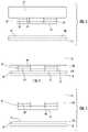
- FIG. 1is a schematic side elevation view of an exemplary tape casting additive manufacturing apparatus that includes a device for measuring the position of a structure;
- FIG. 2is a schematic view of one embodiment of a portion of the tape casting additive manufacturing apparatus shown in FIG. 1 ;
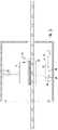
- FIG. 3shows a stylized representation of the initial relative positions of a stage and the platform in an additive manufacturing apparatus
- FIG. 4shows a further relative position of the stage and platform in FIG. 3 ;
- FIG. 5shows a further relative position of the stage and platform in FIG. 3 ;
- FIG. 6shows a stylized representation of a failure mode
- FIG. 7shows a stylized representation of a failure mode
- FIG. 8shows a stylized representation of another failure mode
- FIG. 9shows the results of two cycles of an additive manufacturing method according to the disclosed technology
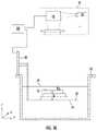
- FIG. 10is a schematic view of a portion of a vat-based additive manufacturing apparatus showing the relative positions of a working surface and a resin surface.
- FIG. 11shows a single layer vat-based additive manufacturing apparatus wherein a layer of resin is being further defined by contact with a stage
- FIG. 12is a view of the single layer vat-based additive manufacturing apparatus of FIG. 11 showing an alternative curing mechanism utilized in the vat-based additive manufacturing apparatus of FIG. 10 .
- FIG. 1illustrates schematically an example of one type of suitable apparatus 10 for additive manufacturing with improved build layer control and thus improved accuracy with regards to final part thickness.
- a methodis provided below for utilizing the apparatus 10 to monitor part geometry via part thickness as the part is built and for modifying a build profile to correct for errors that might occur during the build process.
- the term “build profile”refers to an instruction or set of instructions utilized to operate the apparatus 10 to utilize additive manufacturing to build a group of layers to together define a part having predetermined final dimensions.
- Apparatus 10includes a resin handling assembly 11 which, according to the illustrated embodiment, is a tape casting device 20 .
- Resin handling assembly 11includes a device 76 that is configured to determine the relative positions of a working surface 75 and a resin surface 77 .
- a device 76is shown in FIG. 2 with reference number 76 A to indicate one possible alternative position for the device 76 .
- an additive manufacturing apparatusincludes a stage 14 .
- the stage 14defines a surface 30 on which a part 74 is formed.
- the part 74defines a surface 75 on which a new layer of the part is added by transfer of a cured portion of the layer 110 of resin positioned adjacent the surface 75 and supported by the film 12 .
- the layer 110defines the resin surface 77 .
- error-free operationinvolves a predetermined amount of contact between the surface 75 and the surface 77 .
- the predetermined amount of contactresults in transfer of a cured portion of the layer 110 to form a new build layer 79 of the part 74 and defines a new surface 75 .
- a new portion of layer 110is moved below the part 74 to define a new surface 77 . This configuration is shown in FIG. 5 .
- the layer 110is not thick enough to allow the surface 77 to contact the surface 75 when the stage 14 and the part 74 are moved into a build position appropriate for the existing geometry of the part 74 . In this case, the cured portion of the layer 110 does not transfer to the part 74 .
- the layer 110is too thick such that when the stage 14 and the part 74 are moved into a build position appropriate for the existing geometry of the part 74 , the surface 75 actually penetrates the surface 77 causing malformation of the part and potentially also damaging the part.
- a third error conditionalso shown in FIG. 6
- errors in the thickness of previous layers 110have resulted in a series of layers 79 of part 74 , some or all of which are too thin (a further example of this is shown in FIG. 9 and discussed in detail below).
- the part 74is not as tall as expected and when the stage 14 is moved into a build position that is appropriate for the expected geometry, the surface 75 does not contact the material layer 110 if the thickness of material layer 110 is as thick as expected or thinner.
- a fourth error conditionalso shown in FIG.
- the film 12has contacted the part 74 with such force that the film 12 has been separated in several locations resulting a web breakage or break-out.
- the disclosed technologyaddresses these errors by providing an apparatus and method for accurately defining the thickness of the layer 110 to enable the part 74 to be constructed correctly.
- configurations of the equipment other than tape castingcan be used in apparatus 10 and can carry out a method described below.
- Those other configurationsinclude different types of resin handling equipment such as vats and/or plates.
- the methodis adaptable for use with lower viscosity resins, slurries, and pastes, as well as higher viscosity resins and/or powders.
- Basic components of the exemplary apparatus 10include a material depositing device 106 and the resin handling assembly 11 which in FIG. 1 is the tape casting apparatus 20 .
- the tape casting apparatus 20includes a support film or tape 12 , and a radiant energy apparatus 18 .
- the tape casting apparatus 20includes spaced apart rollers 15 with the flexible polymeric film 12 extending therebetween. A portion of the film 12 is supported from underneath by a support plate 190 . Suitable mechanical supports (frames, brackets, etc.—not shown) would be provided for the rollers 15 and support plate 190 .
- the film 12is an example of a “resin support”.
- Both of the support plate 190 and the film 12are transparent or include a portion or portions that are transparent.
- transparentrefers to a material which allows radiant energy of a selected wavelength to pass through.
- the radiant energy used for curingcould be ultraviolet light or laser light in the visible spectrum.
- transparent materialsinclude polymers, glass, and crystalline minerals such as sapphire or quartz.
- Appropriate meanssuch as motors, actuators, feedback sensors, and/or controls of a known type (not shown) would be provided for driving the rollers 15 in such a manner so as to maintain the film 12 such that it is appropriately tensioned between the rollers 15 and to wind the film 12 from one of the rollers 15 to another roller 15 .
- the film 12 extending between the rollers 15defines a first “build surface” 24 which is shown as being planar, but could alternatively be arcuate (depending on the shape of the support plate).
- the first build surface 24may be considered to be oriented parallel to an X-Y plane of the apparatus 10 , and a direction perpendicular to the X-Y plane is denoted as a Z-direction (X, Y, and Z being three mutually perpendicular directions).
- the first build surface 24may be configured to be “non-stick”, that is, resistant to adhesion of cured resin.
- the non-stick propertiesmay be embodied by a combination of variables such as the chemistry of the film 12 , its surface finish, and/or applied coatings.
- a permanent or semi-permanent non-stick coatingmay be applied.
- a suitable coatingis polytetrafluoroethylene (“PTFE”).
- PTFEpolytetrafluoroethylene
- all or a portion of the first build surface 24may incorporate a controlled roughness or surface texture (e.g. protrusions, dimples, grooves, ridges, etc.) with nonstick properties.
- the film 12may be made in whole or in part from an oxygen-permeable material.
- FIG. 1shows schematically the material depositor 106 configured for this purpose.
- the apparatus 10includes a stage 14 that is a structure defining the planar surface 30 which is capable of being oriented parallel to the build surface 24 of the portion of the film 12 positioned over the support plate 190 .
- Some meansare provided for moving the stage 14 relative to the build surface 24 , parallel to the Z-direction.
- these meansare depicted schematically as a simple actuator 32 connected between the stage 14 and a stationary support structure 34 , with the understanding that devices such as pneumatic cylinders, hydraulic cylinders, ball screw electric actuators, linear electric actuators, or delta drives may be used for this purpose.
- the film 12 and/or the support plate 190could be movable parallel to the Z-direction.
- the apparatus 10includes a radiant energy apparatus 18 that is configured to cure at least a portion of the layer 110 .
- the radiant energy apparatus 18may comprise any device or combination of devices operable to generate and project radiant energy on the resin R in a suitable pattern and with a suitable energy level and other operating characteristics to cure the resin R during the build process, described in more detail below.
- the radiant energy apparatus 18may comprise a “projector” 48 , used herein generally to refer to any device operable to generate a radiant energy patterned image of suitable energy level and other operating characteristics to cure the resin R.
- patterned imagerefers to a projection of radiant energy comprising an array of individual pixels.
- Non-limiting examples of patterned imaged devicesinclude a DLP projector or another digital micro-mirror device, a 2D array of LEDs, a 2D array of lasers, or optically addressed light valves.
- the projector 48comprises a radiant energy source 50 such as a UV lamp, an image forming apparatus 52 operable to receive a source beam 54 from the radiant energy source 50 and generate a pattern image 59 ( FIGS. 6-8 ) to be projected onto the surface of the resin R, and optionally focusing optics 58 , such as one or more lenses.
- a radiant energy source 50such as a UV lamp
- an image forming apparatus 52operable to receive a source beam 54 from the radiant energy source 50 and generate a pattern image 59 ( FIGS. 6-8 ) to be projected onto the surface of the resin R
- optionally focusing optics 58such as one or more lenses.
- the radiant energy source 50may comprise any device operable to generate a beam of suitable energy level and frequency characteristics to cure the resin R.
- the radiant energy source 50comprises a UV flash lamp.
- the image forming apparatus 52may include one or more mirrors, prisms, and/or lenses and is provided with suitable actuators, and arranged so that the source beam 54 from the radiant energy source 50 can be transformed into a pixelated image in an X-Y plane coincident with the surface of the resin R.
- the image forming apparatus 52may be a digital micro-mirror device.
- the projector 48may be a commercially-available Digital Light Processing (“DLP”) projector.
- DLPDigital Light Processing
- the projector 48may incorporate additional means such as actuators, mirrors, etc. configured to selectively move the image forming apparatus 52 or other part of the projector 48 , with the effect of rastering or shifting the location of the patterned image 59 (shown in FIGS. 6-8 ) relative to the build surface 24 .
- the patterned imagemay be moved away from a nominal or starting location. This permits a single image forming apparatus 52 to cover a larger build area, for example.
- Means for mastering or shifting the patterned image from the image forming apparatus 52are commercially available. This type of image projection may be referred to herein as a “tiled image”.
- the radiant energy apparatus 18may comprise a “scanned beam apparatus” 60 used herein to refer generally to refer to any device operable to generate a radiant energy beam of suitable energy level and other operating characteristics to cure the resin R and to scan the beam over the surface of the resin R in a desired pattern.
- the scanned beam apparatus 60comprises a radiant energy source 62 and a beam steering apparatus 64 .
- the radiant energy source 62may comprise any device operable to generate a beam of suitable power and other operating characteristics to cure the resin R.
- suitable radiant energy sourcesinclude lasers or electron beam guns.
- the beam steering apparatus 64may include one or more mirrors, prisms, and/or lenses and may be provided with suitable actuators, and arranged so that a beam 66 from the radiant energy source 62 can be focused to a desired spot size and steered to a desired position in plane coincident with the surface of the resin R.
- the beam 66may be referred to herein as a “build beam”.
- Other types of scanned beam apparatusmay be used. For example, scanned beam sources using multiple build beams are known, as are scanned beam sources in which the radiant energy source itself is movable by way of one or more actuators.
- the apparatus 10may include a controller 68 .
- the controller 68 in FIG. 1is a generalized representation of the hardware and software required to control the operation of the apparatus 10 , the stage 14 , the radiant energy apparatus 18 , the transport mechanism 20 , the depositor 106 , and the various actuators described above.
- the controller 68may be embodied, for example, by software running on one or more processors embodied in one or more devices such as a programmable logic controller (“PLC”) or a microcomputer.
- PLCprogrammable logic controller
- Such processorsmay be coupled to sensors and operating components, for example, through wired or wireless connections.
- the same processor or processorsmay be used to retrieve and analyze sensor data, for statistical analysis, and for feedback control.
- the components of the apparatus 10may be surrounded by a housing 70 , which may be used to provide a shielding or inert gas atmosphere using gas ports 72 .
- pressure within the housing 70could be maintained at a desired level greater than or less than atmospheric.
- the housing 70could be temperature and/or humidity controlled.
- ventilation of the housing 70could be controlled based on factors such as a time interval, temperature, humidity, and/or chemical species concentration.
- the resin Rcomprises a material which is radiant-energy curable and which is capable of adhering or binding together the filler (if used) in the cured state.
- radiant-energy curablerefers to any material which solidifies in response to the application of radiant energy of a particular frequency and energy level.
- the resin Rmay comprise a known type of photopolymer resin containing photo-initiator compounds functioning to trigger a polymerization reaction, causing the resin to change from a liquid state to a solid state.
- the resin Rmay comprise a material which contains a solvent that may be evaporated out by the application of radiant energy.
- the uncured resin Rmay be provided in solid (e.g. granular) or liquid form including a paste or slurry.
- the viscosity of the resin Ris at a higher viscosity such that contact with a doctor blade or a leveling device (such as the stage 14 ) is required.
- the composition of the resin Rmay be selected as desired to suit a particular application. Mixtures of different compositions may be used.
- the resin Rmay be selected to have the ability to out-gas or burn off during further processing, such as the sintering process described below.
- the resin Rmay incorporate a filler.
- the fillermay be pre-mixed with resin R.
- the fillercomprises particles, which are conventionally defined as “a very small bit of matter”.
- the fillermay comprise any material which is chemically and physically compatible with the selected resin R.
- the particlesmay be regular or irregular in shape, may be uniform or non-uniform in size, and may have variable aspect ratios.
- the particlesmay take the form of powder, of small spheres or granules, or may be shaped like small rods or fibers.
- composition of the fillermay be selected as desired to suit a particular application.
- the fillermay be metallic, ceramic, polymeric, and/or organic.
- Other examples of potential fillersinclude diamond, silicon, and graphite. Mixtures of different compositions may be used.
- the fillermay be “fusible”, meaning it is capable of consolidation into a mass upon via application of sufficient energy.
- fusibilityis a characteristic of many available powders including but not limited to: polymeric, ceramic, glass, and metallic.
- the proportion of filler to resin Rmay be selected to suit a particular application. Generally, any amount of filler may be used so long as the combined material is capable of flowing and being leveled, and there is sufficient resin R to hold together the particles of the filler in the cured state.
- the component 74is software modeled as a stack of planar layers 79 arrayed along the Z-axis. Depending on the type of curing method used, each layer may be divided into a grid of pixels. The actual component 74 may be modeled and/or manufactured as a stack of dozens or hundreds of layers. Suitable software modeling processes are known in the art.
- the resin handling assembly 11is operated to provide new resin R in the build zone 23 .
- the apparatus 10is positioned to define a selected layer increment.
- the layer incrementis defined by some combination of the thickness of the deposited layer and the operation of the stage 14 . For a vat system as shown in FIG. 10 , it would be the depth in the vat to which the resin is filled.
- the stage 14could be positioned such that the surface 30 for new parts or the existing surface 75 for parts in process is just touching the applied resin R as shown in FIG. 11 , or the stage 14 could be used to compress and displace the resin R to positively define the layer increment.
- the layer incrementaffects the speed of the additive manufacturing process and the resolution of the component 74 .
- the layer incrementcan be variable, with a larger layer increment being used to speed the process in portions of a component 74 not requiring high accuracy, and a smaller layer increment being used where higher accuracy is required, at the expense of process speed.
- the apparatus 10includes a measuring system 76 .
- the measuring system 76is configured to determine the location of structure within apparatus 10 .
- measuring system 76can be configured to determine distance between structure. Such distances can be used as will be described further below to determine the thickness, i.e., layer increment, of a new build layer 79 .
- the position of the resin surface 77 relative to a reference such as the support 190is constant. It should be appreciated that during normal operation, the position of the resin surface 77 can vary due to variations in the thickness of layer 110 . Such variations can occur in the machine direction (MD) along the Y-axis and in the transverse direction (TD) along the X-axis.
- MDmachine direction
- TDtransverse direction
- the radiant energy apparatus 18is used to cure a two-dimensional cross-section or layer of the component 74 being built as shown in FIG. 3 .
- the projector 48projects the patterned image 59 representative of the cross-section of the component 74 through the film 12 to the resin R. This process is referred to herein as “selective” curing.
- the stage 14is separated from the film 12 , for example by raising the stage 14 using the actuator 32 .
- the resin R and/or cured layerdo not necessarily join, stick, or bond with the surface of the film 12 . Accordingly, as used herein the term “separate” refers to the process of moving two elements apart from each other and does not necessarily imply the act of breaking a bond or detaching one element from another.
- a reference block 78can be utilized according to one aspect of the method described below in the process of measuring.
- the reference block 78is illustrated in FIGS. 1 and 2 is a set of cured layers positioned adjacent the part 74 and as illustrated, representative of the thickness of part 74 at a maximum location.
- the block 78is formed by the curing of a thickness of resin equivalent to the maximum thickness of each build layer 79 .
- the block 78can be a frame surrounding the part 74 as shown to be removed when part 74 is finished.
- the reference block 78can be a discrete block or blocks positioned around the perimeter of the part 74 , to be removed when part 74 is finished.
- the build block 78represents a height that is different than the thickness of part 74 at a maximum location.
- the build block 78can represent a height that is equivalent to the height and a predetermined location within the perimeter of the boundaries of part 74 .
- the build block 78can represent a height at a point a predetermined distance along a line at a predetermined X or Y coordinate.
- the build block 78can represent a height at predetermined XY and Z coordinates. Because the build block 78 can be constructed to vary in height along the X and Y coordinates it can represent different heights and thus different XYZ coordinate combinations.
- the build block 78can be a monolithic structure as illustrated. Alternatively, the build block 78 can be multiple structures.
- the present inventioncan be better understood by a description of the operation thereof.
- a method for producing a part 74 layer by layer using an additive manufacturing apparatus 10is provided.
- the additive manufacturing apparatus 10includes the resin support 190 , the stage 14 , the measuring system 76 , and the actuator configured 32 to change the relative position of the stage 14 and the resin support 190 .
- the methodincludes the steps of: performing an additive manufacturing cycle which includes the following steps: depositing an uncured layer of resin 110 ; moving the stage 14 to a target location (such as a predetermined distance from surface 191 of the resin support 190 ); double checking the actual position of the stage 14 by using the measurement system 76 to determine an actual location of the stage 14 and comparing that actual location to the target location; if the stage 14 is not within predetermined limits from the target location repeat this step of moving the stage 14 to a target location; after one or more movements of the stage 14 , curing the uncured layer of resin 110 ; and moving the stage 14 away from the target location; repeating the additive manufacturing cycle; performing a measuring process wherein the measuring process includes the following steps: using the measuring system 76 to take a measurement indicative of an actual position of a structure relative to the resin support 190 ; comparing the actual position of the structure to an expected position of the structure to determine an error; and using the error to modify the target location.
- a target locationsuch as a predetermined distance from surface 191
- the step of performing a measuring processcan be performed every cycle.
- the step of performing the step of using the errorcan be perform every cycle during which a measuring process is performed.
- an erroris determined each time that the measurement step is performed by comparing the actual position of the structure to the desired position of the structure. For example, if the actual position is expressed as a measure of distance, and the actual distance is compared to a desired distance or setpoint distance.
- An accumulated erroris determined utilizing multiple steps of using the measuring system by adding subsequent step errors to the sum of all previous errors.
- the accumulated errorcan be determined by single measurement of part thickness which will capture the total error accumulated in building of the part.
- the structure to be measuredcan be any one or more of the stage 14 , a surface of the uncured layer of resin 77 , a surface 75 of the part 74 , the surface of the film 12 , the surface 30 of the stage 14 , and a combination thereof.
- the reference pointis the resin support structure 190 and more particularly, the surface 24 of the resin support structure. It should be appreciated that the thickness of the film 12 is accounted for by conventional methods. Measurements taken with regard to a particular reference point such as structure 190 are used to determine the relative positions of structures as is conventionally known.
- the following tableidentifies various measurements that might be used in the method above as shown in FIG. 2 .
- the measurements indicatedare examples and other measurements could be utilized. It should be appreciated that typically these measurements would be expressed as distances, however they could be expressed using a coordinate system utilizing the X, Y, and Z axes indicated above having a common predetermined origin.
- the target locationwould be that location determined by movement of the desired structure the predetermined distance, A.
- the predetermined distance Ais the distance between the surface 75 of the part 74 which can be defined by the reference block 78 used to indicate a particular XYZ coordinate of the surface 75 as discussed above.
- movement of the stage 14 the distance Awould position the surface 75 such that it is immediately adjacent to the surface 77 of the resin 110 .
- the movement of the stage 14 further than distance Awould result in the surface 75 being pushed into the layer 110 to at least partially displace the surface 77 .
- a desired thickness of layer 110can be defined immediately prior to curing.
- Another common measurement usedis the height of a part 74 relative to the surface 30 of the stage 14 “distance G”.
- the distance Gcan be used as described in further detail below in a description of a method for controlling final part height.
- the predetermined distancescan be determined not point-to-point, but by an average of the actual locations or distances of multiple points of the surface to be measured.
- the measuring system 76is configured to determine a plane of the structure by measuring the distance of multiple locations on the structure. It should be appreciated that the locations used to determine an average distance can be varied from cycle to cycle.
- the measuring systemcan be configured to measure a first set of multiple locations after the first cycle and measure a second set of multiple locations after a second cycle and wherein the second set of multiple locations is different than the first set of multiple locations.
- the measurement system 76is configured to generate a signal indicative of position or distances indicated above.
- the signalcan be utilized by the computer 68 as a portion of a closed control loop in which the signal is feedback.
- the closed control loopis configured to adjust the height, as determined relative to a reference such as the resin support structure 190 , of the stage 14 relative to an expected height.
- the expected heightcan be considered the setpoint in the control loop.
- the setpointcan be determined based upon an adjusted distance equal to a predetermined layer thickness plus an amount equal to accumulated error.
- the setpointcan be adjusted for each cycle to accommodate the error. Or optionally, the setpoint can be adjusted after a predetermined number of cycles such that the stage is configured to move the adjusted distance after a predetermined number of cycles.
- the measuring system 76can be used to determine an amount of error in build thickness per layer or group of layers and store or accumulate that error.
- This stored valueis an accumulated error that can be used to control for a final part height.
- the accumulated erroris represented as a value which is adjusted either positively or negatively by the amount of each newly acquired measured error.
- the accumulated errorcan be monitored and compared to a threshold accumulated error value.
- the threshold accumulated error valueis the maximum allowed error in the height of the part 74 or a designated portion of the part 74 .
- a compensation layeris planned.
- the compensation layeris either an existing planned layer currently in the build profile plan that is chosen to be modified or a new layer to be added to the build profile.
- the compensation layeris dimensioned such that either a thickness of the part 74 is within acceptable limits based on the setpoint described above.
- characteristics of the planned layercan be chosen from the following: total planned layer thickness; total compensation layer thickness; geometry of the planned layer; and a combination thereof.
- relevant characteristics of the geometry of the planned layercan include: shape, dimensions, position of the geometry within the layer, the presence of critical dimensions and less critical dimensions of the planned geometry, and a combination thereof.
- planned layers having geometry other than a rectilinear cross-section having uniform thicknessare not used as compensation layers.
- layers having microstructures defined thereinare not used as compensation layers.
- the stage 14can be adjusted to define the final compensation layer thickness. This method does might not provide sufficient range in thickness.
- the compensation layer thicknessis determined by the thickness of the uncured resin layer as deposited. Stated another way, it may be necessary to achieve compensation layer thickness by increasing or decreasing the thickness of the uncured resin layer 110 . It should be appreciated that depending upon the geometry of the part 74 and the amount of the accumulated error multiple compensation layers can be utilized to correct for an accumulated error.
- the following methodutilizes a compensation layer.
- the methodincludes the steps of: operating the additive manufacturing apparatus 10 according to a build profile to create a cured layer of a part; measuring a dimension such as a predetermined thickness or distance, for example the distance G, by operating the measuring system 76 to obtain a measured value; comparing the measured value to a predetermined goal as set by the build profile to determine if a measured error exists; adding the measured error to an accumulated error value; comparing the accumulated error value to a threshold error value; responding to the determination of an error by creating a compensation layer by the following steps when the accumulated error value exceeds the threshold error value: selecting one of the following to be utilized as a compensation layer: a previously planned layer and a new layer; determining the thickness of the compensation layer by using the accumulated error value and modifying the build profile accordingly; building the compensation layer.
- the compensation layercan have a thickness of zero when it is determined that a previously planned layer is to be skipped.
- a compensation layercan be created and built immediately following a specified number of layers or a single layer instead of being based on an accumulated error value is compared to a threshold error value.
- FIG. 9shows an example of a part 74 two cycles being made according to the method above.
- a set of ledger lines 81depicts six planned layers in a build profile. After the fifth cycle as shown, the first five layers are each built such that each is too thin. The amount of error accumulates. Therefore the sixth layer is chosen as a compensating layer. The sixth layer is produced such that it is thicker than originally planned. The total part thickness matches the planned thickness by a combination of the thicker sixth layer and the previous five layers.
- controller 68can be configured to stop or pause building a part, i.e. a stop or pause a “build”.
- a maximum correctioncan be defined within the controller 68 such that it can be configured to determine if the accumulated error is too large to correct for. In such a case, the build can be paused to be resumed after further evaluation or cancelled.
Landscapes
- Chemical & Material Sciences (AREA)
- Engineering & Computer Science (AREA)
- Materials Engineering (AREA)
- Manufacturing & Machinery (AREA)
- Physics & Mathematics (AREA)
- Mechanical Engineering (AREA)
- Optics & Photonics (AREA)
Abstract
Description
| DISTANCE | UPPER STRUCTURE | LOWER STRUCTURE | |
| Working surface | 75 | ||
| Surface | 30 of | Resin surface 77 | |
| Surface | 30 of | Surface of film 12 | |
| D | Working surface 75 | Surface of film 12 | |
| Surface | 30 of | ||
| structure 190 | |||
| F | Working surface 75 | ||
| structure 190 | |||
| Surface | 30 of | ||
Claims (25)
Priority Applications (4)
| Application Number | Priority Date | Filing Date | Title |
|---|---|---|---|
| US16/280,390US11498283B2 (en) | 2019-02-20 | 2019-02-20 | Method and apparatus for build thickness control in additive manufacturing |
| EP20712152.6AEP3927523B1 (en) | 2019-02-20 | 2020-02-20 | Method and apparatus for build thickness control in additive manufacturing |
| CN202080016011.2ACN113508026B (en) | 2019-02-20 | 2020-02-20 | Method and apparatus for build thickness control in additive manufacturing |
| PCT/US2020/018956WO2020172358A1 (en) | 2019-02-20 | 2020-02-20 | Method and apparatus for build thickness control in additive manufacturing |
Applications Claiming Priority (1)
| Application Number | Priority Date | Filing Date | Title |
|---|---|---|---|
| US16/280,390US11498283B2 (en) | 2019-02-20 | 2019-02-20 | Method and apparatus for build thickness control in additive manufacturing |
Publications (2)
| Publication Number | Publication Date |
|---|---|
| US20200262151A1 US20200262151A1 (en) | 2020-08-20 |
| US11498283B2true US11498283B2 (en) | 2022-11-15 |
Family
ID=69845591
Family Applications (1)
| Application Number | Title | Priority Date | Filing Date |
|---|---|---|---|
| US16/280,390Active2039-07-10US11498283B2 (en) | 2019-02-20 | 2019-02-20 | Method and apparatus for build thickness control in additive manufacturing |
Country Status (4)
| Country | Link |
|---|---|
| US (1) | US11498283B2 (en) |
| EP (1) | EP3927523B1 (en) |
| CN (1) | CN113508026B (en) |
| WO (1) | WO2020172358A1 (en) |
Families Citing this family (3)
| Publication number | Priority date | Publication date | Assignee | Title |
|---|---|---|---|---|
| EP4111351A4 (en) | 2020-03-25 | 2024-03-20 | OPT Industries, Inc. | SYSTEMS, METHODS AND FILE FORMAT FOR 3D PRINTING OF MICROSTRUCTURES |
| WO2023003512A2 (en)* | 2021-07-21 | 2023-01-26 | Phasio Pte. Ltd. | Additive manufacturing method and apparatus |
| CN114701166A (en)* | 2022-03-31 | 2022-07-05 | 苏州研拓自动化科技有限公司 | Control method for deformation of large-size high polymer material 3D printing material |
Citations (234)
| Publication number | Priority date | Publication date | Assignee | Title |
|---|---|---|---|---|
| US4575330A (en) | 1984-08-08 | 1986-03-11 | Uvp, Inc. | Apparatus for production of three-dimensional objects by stereolithography |
| US4752498A (en) | 1987-03-02 | 1988-06-21 | Fudim Efrem V | Method and apparatus for production of three-dimensional objects by photosolidification |
| US5026146A (en) | 1989-04-03 | 1991-06-25 | Hug William F | System for rapidly producing plastic parts |
| US5031120A (en) | 1987-12-23 | 1991-07-09 | Itzchak Pomerantz | Three dimensional modelling apparatus |
| US5059021A (en) | 1988-04-18 | 1991-10-22 | 3D Systems, Inc. | Apparatus and method for correcting for drift in production of objects by stereolithography |
| US5096530A (en) | 1990-06-28 | 1992-03-17 | 3D Systems, Inc. | Resin film recoating method and apparatus |
| US5104592A (en) | 1988-04-18 | 1992-04-14 | 3D Systems, Inc. | Method of and apparatus for production of three-dimensional objects by stereolithography with reduced curl |
| US5126529A (en) | 1990-12-03 | 1992-06-30 | Weiss Lee E | Method and apparatus for fabrication of three-dimensional articles by thermal spray deposition |
| US5126259A (en) | 1987-12-24 | 1992-06-30 | Takeda Chemical Industries, Ltd. | Human b. lymphoblastoid cell, hybridoma, antibody and production of antibody |
| WO1992011577A1 (en) | 1990-12-21 | 1992-07-09 | Eos Gmbh Electro Optical Systems | Process and device for producing a three-dimensional object |
| US5133987A (en) | 1989-10-27 | 1992-07-28 | 3D Systems, Inc. | Stereolithographic apparatus and method |
| US5174931A (en) | 1988-09-26 | 1992-12-29 | 3D Systems, Inc. | Method of and apparatus for making a three-dimensional product by stereolithography |
| US5182055A (en) | 1988-04-18 | 1993-01-26 | 3D Systems, Inc. | Method of making a three-dimensional object by stereolithography |
| US5192559A (en) | 1990-09-27 | 1993-03-09 | 3D Systems, Inc. | Apparatus for building three-dimensional objects with sheets |
| US5203944A (en) | 1991-10-10 | 1993-04-20 | Prinz Fritz B | Method for fabrication of three-dimensional articles by thermal spray deposition using masks as support structures |
| US5204055A (en) | 1989-12-08 | 1993-04-20 | Massachusetts Institute Of Technology | Three-dimensional printing techniques |
| US5207371A (en) | 1991-07-29 | 1993-05-04 | Prinz Fritz B | Method and apparatus for fabrication of three-dimensional metal articles by weld deposition |
| US5236637A (en) | 1984-08-08 | 1993-08-17 | 3D Systems, Inc. | Method of and apparatus for production of three dimensional objects by stereolithography |
| US5258146A (en) | 1988-09-26 | 1993-11-02 | 3D Systems, Inc. | Method of and apparatus for measuring and controlling fluid level in stereolithography |
| US5314711A (en) | 1991-09-30 | 1994-05-24 | Gisulfo Baccini | Method and apparatus for printing green-tape foil circuits |
| US5387380A (en) | 1989-12-08 | 1995-02-07 | Massachusetts Institute Of Technology | Three-dimensional printing techniques |
| US5432045A (en) | 1992-05-28 | 1995-07-11 | Cmet, Inc. | Photo-solidification modeling apparatus and photo-solidification modeling method having an improved recoating process |
| US5447822A (en) | 1989-09-28 | 1995-09-05 | 3D Systems, Inc. | Apparatus and related method for forming a substantially flat stereolithographic working surface |
| US5454069A (en) | 1992-08-25 | 1995-09-26 | University Of Kentucky Research Foundation | Process for converting serial image to the sterolithography apparatus (SLA) slice file with automatic base and support generation |
| US5496682A (en) | 1993-10-15 | 1996-03-05 | W. R. Grace & Co.-Conn. | Three dimensional sintered inorganic structures using photopolymerization |
| US5626919A (en) | 1990-03-01 | 1997-05-06 | E. I. Du Pont De Nemours And Company | Solid imaging apparatus and method with coating station |
| US5650260A (en) | 1993-10-14 | 1997-07-22 | Teijin Seiki Co., Ltd. | Method and apparatus for fabricating three-dimensional object |
| US5660621A (en) | 1995-12-29 | 1997-08-26 | Massachusetts Institute Of Technology | Binder composition for use in three dimensional printing |
| US5665401A (en) | 1995-04-25 | 1997-09-09 | Eos Gmbh Electro Optical Systems | Apparatus for producing an object using stereolithography |
| US5697043A (en) | 1996-05-23 | 1997-12-09 | Battelle Memorial Institute | Method of freeform fabrication by selective gelation of powder suspensions |
| US5718279A (en) | 1995-11-09 | 1998-02-17 | Toyota Jidosha Kabushiki Kaisha | Method for laminate forming a sand mould and a method for producing a casting using the same |
| WO1998006560A1 (en) | 1996-08-08 | 1998-02-19 | Sri International | Apparatus for automated fabrication of three-dimensional objects, and associated methods of use |
| US5824184A (en) | 1994-08-10 | 1998-10-20 | Seiko Epson Corporation | Structure for removing a peel-off backing from an adhesive tape |
| US5940674A (en) | 1997-04-09 | 1999-08-17 | Massachusetts Institute Of Technology | Three-dimensional product manufacture using masks |
| US5985204A (en) | 1997-04-25 | 1999-11-16 | Toyota Jidosha Kabushiki Kasiha | Method for producing laminated object |
| US6051179A (en) | 1997-03-19 | 2000-04-18 | Replicator Systems, Inc. | Apparatus and method for production of three-dimensional models by spatial light modulator |
| US6146567A (en) | 1993-02-18 | 2000-11-14 | Massachusetts Institute Of Technology | Three dimensional printing methods |
| US6193923B1 (en) | 1995-09-27 | 2001-02-27 | 3D Systems, Inc. | Selective deposition modeling method and apparatus for forming three-dimensional objects and supports |
| US6200646B1 (en) | 1999-08-25 | 2001-03-13 | Spectra Group Limited, Inc. | Method for forming polymeric patterns, relief images and colored polymeric bodies using digital light processing technology |
| US6206672B1 (en) | 1994-03-31 | 2001-03-27 | Edward P. Grenda | Apparatus of fabricating 3 dimensional objects by means of electrophotography, ionography or a similar process |
| US6363606B1 (en) | 1998-10-16 | 2002-04-02 | Agere Systems Guardian Corp. | Process for forming integrated structures using three dimensional printing techniques |
| US6376148B1 (en) | 2001-01-17 | 2002-04-23 | Nanotek Instruments, Inc. | Layer manufacturing using electrostatic imaging and lamination |
| US6401002B1 (en) | 1999-04-29 | 2002-06-04 | Nanotek Instruments, Inc. | Layer manufacturing apparatus and process |
| US6403002B1 (en) | 1997-05-14 | 2002-06-11 | Buss Muller Technology Gmbh | Method and device for producing a shaped body |
| US6436520B1 (en) | 1999-09-01 | 2002-08-20 | Toda Kogyo Corporation | Magnetic display device |
| US6471800B2 (en) | 2000-11-29 | 2002-10-29 | Nanotek Instruments, Inc. | Layer-additive method and apparatus for freeform fabrication of 3-D objects |
| US20020165635A1 (en)* | 2001-05-02 | 2002-11-07 | Farren Chris E. | Method of forming finished parts utilizing stereolithography technology |
| JP2002370286A (en) | 2001-04-23 | 2002-12-24 | Envision Technologies Gmbh | Apparatus and method for separating material layer |
| US6500378B1 (en) | 2000-07-13 | 2002-12-31 | Eom Technologies, L.L.C. | Method and apparatus for creating three-dimensional objects by cross-sectional lithography |
| JP2003039564A (en) | 2001-04-20 | 2003-02-13 | Envision Technologies Gmbh | Apparatus for forming three-dimensional matter |
| US6575218B1 (en) | 1993-11-24 | 2003-06-10 | Marshall Burns | Method and apparatus for automatic fabrication of three dimensional object |
| US6596224B1 (en) | 1996-05-24 | 2003-07-22 | Massachusetts Institute Of Technology | Jetting layers of powder and the formation of fine powder beds thereby |
| US20030180171A1 (en) | 2001-03-07 | 2003-09-25 | Advanced Ceramics Research, Inc. | Method for preparation of metallic and ceramic foam products and products made |
| US6780368B2 (en) | 2001-04-10 | 2004-08-24 | Nanotek Instruments, Inc. | Layer manufacturing of a multi-material or multi-color 3-D object using electrostatic imaging and lamination |
| JP2004257929A (en) | 2003-02-27 | 2004-09-16 | Dainippon Printing Co Ltd | Transfer foil defect inspection equipment |
| US6838035B1 (en) | 1999-10-08 | 2005-01-04 | Voxeljet Technology Gmbh | Rapid-prototyping method and apparatus |
| US6850334B1 (en) | 2000-01-18 | 2005-02-01 | Objet Geometries Ltd | System and method for three dimensional model printing |
| US6896839B2 (en) | 2001-02-07 | 2005-05-24 | Minolta Co., Ltd. | Three-dimensional molding apparatus and three-dimensional molding method |
| US6930144B2 (en) | 2003-06-24 | 2005-08-16 | Hewlett-Packard Development Company, L.P. | Cement system including a binder for use in freeform fabrication |
| US6966960B2 (en) | 2003-05-07 | 2005-11-22 | Hewlett-Packard Development Company, L.P. | Fusible water-soluble films for fabricating three-dimensional objects |
| US6974521B2 (en) | 2000-10-18 | 2005-12-13 | Katholieke Universiteit Nijmegen | Method for separating a film and a substrate |
| US6986654B2 (en) | 2002-07-03 | 2006-01-17 | Therics, Inc. | Apparatus, systems and methods for use in three-dimensional printing |
| US7022207B2 (en) | 2002-04-03 | 2006-04-04 | 3M Innovative Properties Company | Method and apparatus for peeling a thin film from a liner |
| WO2006077665A1 (en) | 2005-01-20 | 2006-07-27 | National University Corporation NARA Institute of Science and Technology | Projection device, control method for projection device, composite projection system, control program for projection device, and recording medium having projection device control program recorded therein |
| US7087109B2 (en) | 2002-09-25 | 2006-08-08 | Z Corporation | Three dimensional printing material system and method |
| US7270528B2 (en) | 2002-05-07 | 2007-09-18 | 3D Systems, Inc. | Flash curing in selective deposition modeling |
| US7300613B2 (en) | 2003-05-09 | 2007-11-27 | Fujifilm Corporation | Process for producing three-dimensional model, and three-dimensional model |
| US7351304B2 (en) | 2005-05-24 | 2008-04-01 | General Electric Company | Method and apparatus for reducing surface defects |
| US20080170112A1 (en) | 2007-01-17 | 2008-07-17 | Hull Charles W | Build pad, solid image build, and method for building build supports |
| US7455804B2 (en) | 2001-02-15 | 2008-11-25 | Huntsman Advanced Materials Americas Inc. | Three-dimensional structured printing |
| US7520740B2 (en) | 2005-09-30 | 2009-04-21 | 3D Systems, Inc. | Rapid prototyping and manufacturing system and method |
| US7550518B2 (en) | 2000-04-14 | 2009-06-23 | Z Corporation | Methods and compositions for three-dimensional printing of solid objects |
| US7572403B2 (en) | 2003-09-04 | 2009-08-11 | Peihua Gu | Multisource and multimaterial freeform fabrication |
| US7578958B2 (en) | 2001-05-24 | 2009-08-25 | Huntsman Advanced Materials Americas Inc. | Three-dimensional structured printing |
| US7614866B2 (en) | 2007-01-17 | 2009-11-10 | 3D Systems, Inc. | Solid imaging apparatus and method |
| US7636610B2 (en) | 2006-07-19 | 2009-12-22 | Envisiontec Gmbh | Method and device for producing a three-dimensional object, and computer and data carrier useful therefor |
| US20100003619A1 (en) | 2008-05-05 | 2010-01-07 | Suman Das | Systems and methods for fabricating three-dimensional objects |
| US7698947B2 (en) | 2005-08-26 | 2010-04-20 | The Boeing Company | Rapid prototype integrated matrix ultrasonic transducer array inspection apparatus, systems, and methods |
| US7706910B2 (en) | 2007-01-17 | 2010-04-27 | 3D Systems, Inc. | Imager assembly and method for solid imaging |
| US20100125356A1 (en)* | 2008-11-18 | 2010-05-20 | Global Filtration Systems | System and Method for Manufacturing |
| US7783371B2 (en) | 2006-04-28 | 2010-08-24 | Envisiontec Gmbh | Device and method for producing a three-dimensional object by means of mask exposure |
| US7785093B2 (en) | 2004-10-08 | 2010-08-31 | 3D Systems, Inc. | Stereolithographic apparatus |
| US7790093B2 (en) | 2004-05-10 | 2010-09-07 | Envisiontec Gmbh | Process for the production of a three-dimensional object with resolution improvement by “pixel-shift” |
| US7795349B2 (en) | 1999-11-05 | 2010-09-14 | Z Corporation | Material systems and methods of three-dimensional printing |
| US7815826B2 (en) | 2004-05-12 | 2010-10-19 | Massachusetts Institute Of Technology | Manufacturing process, such as three-dimensional printing, including solvent vapor filming and the like |
| US7845930B2 (en) | 2004-05-07 | 2010-12-07 | Envisiontec Gmbh | Process for the production of a three-dimensional object with an improved separation of hardened material layers from a construction plane |
| US7867302B2 (en) | 2005-02-22 | 2011-01-11 | Saint-Gobain Abrasives, Inc. | Rapid tooling system and methods for manufacturing abrasive articles |
| US7892474B2 (en) | 2006-11-15 | 2011-02-22 | Envisiontec Gmbh | Continuous generative process for producing a three-dimensional object |
| US7894921B2 (en) | 2006-04-28 | 2011-02-22 | Envisiontec Gmbh | Device and method for producing a three-dimensional object by means of mask exposure |
| US20110089610A1 (en) | 2009-10-19 | 2011-04-21 | Global Filtration Systems | Resin Solidification Substrate and Assembly |
| US8003040B2 (en) | 2007-10-26 | 2011-08-23 | Envisiontec Gmbh | Process and freeform fabrication system for producing a three-dimensional object |
| US8017055B2 (en) | 1996-12-20 | 2011-09-13 | Z Corporation | Three-dimensional printer |
| US8029642B2 (en) | 2007-07-27 | 2011-10-04 | The Boeing Company | Tape removal apparatus and process |
| US8048261B2 (en) | 2007-08-10 | 2011-11-01 | The Boeing Company | Tape removal apparatus and process for use with an automated composite tape laying machine |
| US8096262B2 (en) | 2004-02-19 | 2012-01-17 | Ingo Ederer | Method and device for applying fluids |
| US8105066B2 (en) | 2007-01-17 | 2012-01-31 | 3D Systems, Inc. | Cartridge for solid imaging apparatus and method |
| US8157908B2 (en) | 2006-12-08 | 2012-04-17 | 3D Systems, Inc. | Three dimensional printing material system and method using peroxide cure |
| US8185229B2 (en) | 2006-05-26 | 2012-05-22 | 3D Systems, Inc. | Apparatus and methods for handling materials in a 3-D printer |
| US8191500B2 (en) | 2005-11-24 | 2012-06-05 | Kronoplus Technical Ag | Coating device comprising flowing coating material for smooth or structured surfaces |
| US8211226B2 (en) | 2010-01-15 | 2012-07-03 | Massachusetts Institute Of Technology | Cement-based materials system for producing ferrous castings using a three-dimensional printer |
| US20120195994A1 (en) | 2011-01-31 | 2012-08-02 | Global Filtration Systems | Method and apparatus for making three-dimensional objects from multiple solidifiable materials |
| US8282866B2 (en) | 2008-06-30 | 2012-10-09 | Seiko Epson Corporation | Method and device for forming three-dimensional model, sheet material processing method, and sheet material processing device |
| US8326024B2 (en) | 2009-04-14 | 2012-12-04 | Global Filtration Systems | Method of reducing the force required to separate a solidified object from a substrate |
| US8424580B2 (en) | 2007-05-21 | 2013-04-23 | The Boeing Company | Auto lamination cassette apparatus |
| US8444903B2 (en) | 2007-07-13 | 2013-05-21 | The Boeing Company | Method of fabricating three dimensional printed part |
| US8475946B1 (en) | 2007-03-20 | 2013-07-02 | Bowling Green State University | Ceramic article and method of manufacture |
| US8506862B2 (en) | 2007-02-22 | 2013-08-13 | 3D Systems, Inc. | Three dimensional printing material system and method using plasticizer-assisted sintering |
| US8506870B2 (en) | 2003-06-16 | 2013-08-13 | Voxeljet Technology Gmbh | Methods of manufacturing layered three-dimensional forms |
| US8568646B2 (en) | 2008-10-20 | 2013-10-29 | 3D Systems, Inc. | Compensation of actinic radiation intensity profiles for three-dimensional modelers |
| US8568649B1 (en) | 2007-03-20 | 2013-10-29 | Bowling Green State University | Three-dimensional printer, ceramic article and method of manufacture |
| US8616872B2 (en) | 2010-02-02 | 2013-12-31 | Sony Corporation | Three-dimensional modeling apparatus, method of manufacturing a three-dimensional object and three-dimensional object |
| US8623264B2 (en) | 2008-10-20 | 2014-01-07 | Ivoclar Vivadent Ag | Device and method for processing light-polymerizable material for building up an object in layers |
| US8636494B2 (en) | 2002-12-03 | 2014-01-28 | Stratasys Ltd. | Apparatus for printing of three-dimensional objects |
| US20140036455A1 (en)* | 2011-04-17 | 2014-02-06 | Stratasys Ltd. | System and method for additive manufacturing of an object |
| US8715832B2 (en) | 2008-11-20 | 2014-05-06 | Voxeljet Ag | Method for the layered construction of plastic models |
| US8741203B2 (en) | 2008-10-20 | 2014-06-03 | Ivoclar Vivadent Ag | Device and method for processing light-polymerizable material for building up an object in layers |
| US8741194B1 (en) | 2000-09-25 | 2014-06-03 | Voxeljet Ag | Method for producing a part using a depostion technique |
| US8761918B2 (en) | 2003-01-16 | 2014-06-24 | 3D Systems, Inc. | Printing system for forming three dimensional objects |
| US20140239554A1 (en) | 2007-07-04 | 2014-08-28 | Envisiontec Gmbh | Process and device for producing a three-dimensional object |
| US20140275317A1 (en) | 2013-03-15 | 2014-09-18 | 3D Systems, Inc. | Three dimensional printing material system and method |
| US8844133B2 (en) | 2008-02-28 | 2014-09-30 | The Aerospace Corporation | Stereolithographic rocket motor manufacturing method |
| US8873024B2 (en) | 2009-03-06 | 2014-10-28 | Nederlandse Organisatie Voor Toegepast-Natuurwetenschappelijk Onderzoek Tno | Illumination system for use in a stereolithography apparatus |
| US8876513B2 (en) | 2008-04-25 | 2014-11-04 | 3D Systems, Inc. | Selective deposition modeling using CW UV LED curing |
| US8888480B2 (en) | 2012-09-05 | 2014-11-18 | Aprecia Pharmaceuticals Company | Three-dimensional printing system and equipment assembly |
| US8915728B2 (en) | 2012-01-27 | 2014-12-23 | United Technologies Corporation | Multi-dimensional component build system and process |
| US20150004042A1 (en) | 2009-07-23 | 2015-01-01 | Didier NIMAL | Biomedical device, method for manufacturing the same and use thereof |
| US8926304B1 (en) | 2013-11-20 | 2015-01-06 | Xyzprinting, Inc. | Three-dimensional printing apparatus |
| US8932511B2 (en) | 2000-03-13 | 2015-01-13 | Stratasys Ltd. | Method of making a composite material by three-dimensional ink-jet printing |
| US20150056365A1 (en) | 2012-06-20 | 2015-02-26 | Panasonic Corporation | Method for inspecting solution discharge apparatus and method for producing device |
| US8968625B2 (en) | 2009-11-26 | 2015-03-03 | Yu En Tan | Process for building three-dimensional objects |
| US8991211B1 (en) | 2009-11-01 | 2015-03-31 | The Exone Company | Three-dimensional printing glass articles |
| US8998601B2 (en) | 2010-05-17 | 2015-04-07 | Dws S.R.L. | Stereolithography machine |
| US20150102531A1 (en) | 2013-10-11 | 2015-04-16 | Global Filtration Systems, A Dba Of Gulf Filtration Systems Inc. | Apparatus and method for forming three-dimensional objects using a curved build platform |
| US20150104563A1 (en) | 2013-10-14 | 2015-04-16 | Valco Cincinnati, Inc. | Device and method for verifying the construction of adhesively-attached substrates |
| US9031680B2 (en) | 2007-07-25 | 2015-05-12 | Stratasys Ltd. | Solid freeform fabrication using a plurality of modeling materials |
| US20150145174A1 (en) | 2013-11-22 | 2015-05-28 | Stratasys, Inc. | Magnetic platen assembly for additive manufacturing system |
| US20150165695A1 (en) | 2013-12-13 | 2015-06-18 | Xyzprinting, Inc. | Three dimensional printing apparatus |
| US9064922B2 (en) | 2011-03-30 | 2015-06-23 | SCREEN Holdings Co., Ltd. | Substrate inspection apparatus and substrate inspection method |
| US9073260B2 (en) | 2011-06-28 | 2015-07-07 | Global Filtration Systems | Apparatus and method for forming three-dimensional objects using linear solidification |
| US9101321B1 (en) | 2014-02-11 | 2015-08-11 | Brian Kieser | Unique device identification through high data density structural encoding |
| US20150224710A1 (en) | 2014-02-10 | 2015-08-13 | Global Filtration Systems, A Dba Of Gulf Filtration Systems Inc. | Apparatus and method for forming three-dimensional objects from solidifiable paste |
| US20150231831A1 (en) | 2014-02-20 | 2015-08-20 | Global Filtration Systems, A Dba Of Gulf Filtration Systems Inc. | Apparatus and method for forming three-dimensional objects using a tilting solidification substrate |
| US20150231828A1 (en) | 2014-02-20 | 2015-08-20 | Global Filtration Systems, A Dba Of Gulf Filtration Systems Inc. | Apparatus and method for forming three-dimensional objects using a tilting solidification substrate |
| US9150032B2 (en) | 2011-08-31 | 2015-10-06 | Xerox Corporation | Methods, apparatus, and systems for controlling an initial line width of radiation curable gel ink |
| US20150301517A1 (en) | 2014-04-18 | 2015-10-22 | Xyzprinting, Inc. | Three dimensional printing apparatus and method for detecting printing anomaly |
| US20150306825A1 (en) | 2014-04-29 | 2015-10-29 | Xyzprinting, Inc. | Three-dimensional printing apparatus |
| US20150321421A1 (en) | 2014-05-12 | 2015-11-12 | Xyzprinting, Inc. | Method for detecting characteristic of forming material and three-dimensional printing apparatus |
| US9205601B2 (en) | 2013-02-12 | 2015-12-08 | Carbon3D, Inc. | Continuous liquid interphase printing |
| US20150355553A1 (en) | 2013-01-09 | 2015-12-10 | Prodways | Production of a volume object by lithography, having improved spatial resolution |
| US9233504B2 (en) | 2012-10-29 | 2016-01-12 | Makerbot Industries, Llc | Tagged build material for three-dimensional printing |
| US20160016361A1 (en) | 2014-07-17 | 2016-01-21 | Formlabs, Inc. | Systems and methods for an improved peel operation during additive fabrication |
| US9248600B2 (en) | 2014-05-28 | 2016-02-02 | Makerbot Industries, Llc | Build platform leveling and homing |
| US20160031010A1 (en) | 2013-03-05 | 2016-02-04 | United Technologies Corporation | Build platforms for additive manufacturing |
| US20160046075A1 (en) | 2014-08-12 | 2016-02-18 | Carbon3D, Inc. | Three-dimensional printing with supported build plates |
| US20160046080A1 (en) | 2014-08-18 | 2016-02-18 | Formlabs, Inc. | Systems and methods for an improved peel operation during additive fabrication |
| US20160052205A1 (en) | 2014-08-20 | 2016-02-25 | Formlabs, Inc. | Techniques for applying a peel operation during additive fabrication and related systems and methods |
| US20160059485A1 (en) | 2014-08-29 | 2016-03-03 | Xyzprinting, Inc. | Three-dimensional printing apparatus and method for three-dimensional printing |
| US20160082671A1 (en) | 2012-05-03 | 2016-03-24 | B9Creations, LLC | Solid imaging apparatus with improved part separation from the image plate |
| US20160096332A1 (en) | 2014-10-02 | 2016-04-07 | Xyzprinting, Inc. | Three dimensional printing apparatus and printing method thereof |
| US9308690B2 (en) | 2012-07-31 | 2016-04-12 | Makerbot Industries, Llc | Fabrication of objects with enhanced structural characteristics |
| US20160107387A1 (en) | 2013-06-28 | 2016-04-21 | Cmet Inc. | Three-dimensional fabricating apparatus and method of fabricate three-dimensional shaped object |
| US20160107340A1 (en) | 2014-04-02 | 2016-04-21 | B9Creations, LLC | Additive Manufacturing Device With Sliding Plate and Peeling Film |
| US9327385B2 (en) | 2011-12-30 | 2016-05-03 | Diamond Innovations, Inc. | Near-net cutting tool insert |
| US20160129631A1 (en) | 2014-11-10 | 2016-05-12 | Xyzprinting, Inc. | Three dimensional printing apparatus |
| US9360757B2 (en) | 2013-08-14 | 2016-06-07 | Carbon3D, Inc. | Continuous liquid interphase printing |
| US20160193785A1 (en) | 2015-01-02 | 2016-07-07 | Voxel8, Inc. | 3d printer for printing a plurality of material types |
| US20160214327A1 (en) | 2011-03-02 | 2016-07-28 | Bego Medical Gmbh | Device for the generative manufacturing of three-dimensional components |
| US20160221262A1 (en) | 2008-05-05 | 2016-08-04 | Suman Das | Systems and methods for fabricating three-dimensional objects |
| US9415544B2 (en) | 2006-08-29 | 2016-08-16 | 3D Systems, Inc. | Wall smoothness, feature accuracy and resolution in projected images via exposure levels in solid imaging |
| US9429104B2 (en) | 2011-08-01 | 2016-08-30 | The Aerospace Corporation | Systems and methods for casting hybrid rocket motor fuel grains |
| US9434107B2 (en) | 2010-01-12 | 2016-09-06 | Dws S.R.L. | Modeling plate for a stereolithography machine, stereolithography machine using said modeling plate and tool for cleaning said modeling plate |
| US9446557B2 (en) | 2011-01-18 | 2016-09-20 | Dws S.R.L. | Method for producing a three-dimensional object and stereolithography machine employing said method |
| US9453142B2 (en) | 2014-06-23 | 2016-09-27 | Carbon3D, Inc. | Polyurethane resins having multiple mechanisms of hardening for use in producing three-dimensional objects |
| US9457374B2 (en) | 2013-11-08 | 2016-10-04 | Upm Raflatac Oy | Method and apparatus for curtain coating |
| US20160288413A1 (en)* | 2015-04-02 | 2016-10-06 | Massivit 3D Printing Technologies Ltd | Additive Manufacturing Device |
| US9469074B2 (en) | 2007-10-21 | 2016-10-18 | Voxeljet Ag | Method and device for conveying particulate material during the layer-wise production of patterns |
| US20160303798A1 (en) | 2013-12-20 | 2016-10-20 | United Technologies Corporation | Method and device for manufacturing of three dimensional objects utilizing direct plasma arc |
| US9487443B2 (en) | 2014-03-14 | 2016-11-08 | Ricoh Company, Ltd. | Layer stack formation powder material, powder layer stack formation hardening liquid, layer stack formation material set, and layer stack object formation method |
| US20160332386A1 (en) | 2014-01-15 | 2016-11-17 | Admatec Europe B.V. | Additive manufacturing system for manufacturing a three dimensional object |
| US9498920B2 (en) | 2013-02-12 | 2016-11-22 | Carbon3D, Inc. | Method and apparatus for three-dimensional fabrication |
| US9529371B2 (en) | 2013-07-10 | 2016-12-27 | Roland Dg Corporation | Image projection system and image projection method |
| US9539762B2 (en) | 2013-03-22 | 2017-01-10 | Markforged, Inc. | 3D printing with kinematic coupling |
| US20170008236A1 (en) | 2012-03-02 | 2017-01-12 | Dynamic Material Systems, LLC | Additive Manufacturing 3D Printing of Advanced Ceramics |
| US20170008234A1 (en) | 2013-03-15 | 2017-01-12 | 3D Systems, Inc. | Powder Distribution for Laser Sintering Systems |
| US9545753B2 (en) | 2011-04-20 | 2017-01-17 | Dws S.R.L. | Method for producing a three-dimensional object and stereolithography machine employing said method |
| US9545784B2 (en) | 2013-06-25 | 2017-01-17 | Roland Dg Corporation | Projection image correction system and projection image correction method |
| WO2017009368A1 (en) | 2015-07-15 | 2017-01-19 | Admatec Europe B.V. | Additive manufacturing device for manufacturing a three dimensional object |
| US9578695B2 (en) | 2011-03-24 | 2017-02-21 | Fundacio Privada Ascamm | Method and devices for solid structure formation by localized microwaves |
| US9579852B2 (en) | 2014-01-30 | 2017-02-28 | Seiko Epson Corporation | Method for manufacturing three-dimensional shaped object |
| US9581530B2 (en) | 2014-07-09 | 2017-02-28 | Brigham Young University | Multichannel impact response for material characterization |
| US20170066196A1 (en) | 2015-09-04 | 2017-03-09 | Feetz, Inc. | Systems and methods for wave function based additive manufacturing |
| US20170066185A1 (en) | 2015-09-09 | 2017-03-09 | Carbon3D, Inc. | Method and apparatus for three-dimensional fabrication |
| US9592635B2 (en) | 2012-06-04 | 2017-03-14 | Ivoclar Vivadent Ag | Method for the construction of a shaped body |
| US20170080641A1 (en) | 2014-02-20 | 2017-03-23 | Global Filtration Systems, A Dba Of Gulf Filtration Systems Inc. | Apparatus and method for forming three-dimensional objects using a tilting solidification substrate |
| US9604411B2 (en) | 2014-05-04 | 2017-03-28 | Eoplex Limited | Multi-material three dimensional printer |
| US20170087670A1 (en) | 2015-09-28 | 2017-03-30 | Ecole Polytechnique Federale De Lausanne (Epfl) | Method and Device for Implementing Laser Shock Peening or Warm Laser Shock Peening During Selective Laser Melting |
| US20170100897A1 (en) | 2015-10-13 | 2017-04-13 | Xyzprinting, Inc. | Three-dimensional printing device |
| US20170102679A1 (en) | 2015-10-07 | 2017-04-13 | Autodesk, Inc. | Sub-pixel grayscale three-dimensional printing |
| US20170100895A1 (en) | 2015-10-13 | 2017-04-13 | Xyzprinting, Inc. | Methof for calibrating a light of a three-dimensional object generating apparatus |
| US9632983B2 (en) | 2014-04-08 | 2017-04-25 | Roland Dg Corporation | Image projection system and image projection method |
| US20170113409A1 (en) | 2015-10-23 | 2017-04-27 | Makerbot Industries, Llc | Build patterns for surfaces of a three-dimensionally printed object |
| US20170120333A1 (en) | 2015-10-30 | 2017-05-04 | Seurat Technologies, Inc. | Enclosed Additive Manufacturing System |
| US9649815B2 (en) | 2015-04-22 | 2017-05-16 | Xerox Corporation | Coating for precision rails and a system for cleaning precision rails in three-dimensional object printing systems |
| US9649812B2 (en) | 2011-01-05 | 2017-05-16 | Voxeljet Ag | Device and method for constructing a laminar body comprising at least one position-adjustable body defining the working area |
| US20170136688A1 (en) | 2015-11-13 | 2017-05-18 | Paxis Llc | Additive Manufacturing Apparatus, System, and Method |
| US9670371B2 (en) | 2013-01-11 | 2017-06-06 | Ceraloc Innovation Ab | Digital thermal binder and powder printing |
| US9676143B2 (en) | 2006-08-10 | 2017-06-13 | Voxeljet Ag | Self-hardening material and process for layerwise formation of models |
| US20170165916A1 (en) | 2015-12-11 | 2017-06-15 | Global Filtration Systems, A Dba Of Gulf Filtration Systems Inc. | Method and apparatus for concurrently making multiple three-dimensional objects from multiple solidifiable materials |
| US9682425B2 (en) | 2009-12-08 | 2017-06-20 | Baker Hughes Incorporated | Coated metallic powder and method of making the same |
| US9682166B2 (en) | 2014-08-11 | 2017-06-20 | Ricoh Company, Ltd. | Additive manufacturing powder and method of manufacturing the same |
| US20170173865A1 (en) | 2014-02-10 | 2017-06-22 | Stratasys Ltd. | Composition and method for additive manufacturing of an object |
| US20170182708A1 (en) | 2015-12-09 | 2017-06-29 | Autodesk, Inc. | Multi-material stereolithographic three dimensional printing |
| US20170190120A1 (en) | 2016-01-06 | 2017-07-06 | Autodesk, Inc. | Controllable release build plate for 3d printer |
| CN107053663A (en) | 2017-06-27 | 2017-08-18 | 上海联泰三维科技有限公司 | Optical system, irradiation control method and the 3D printing equipment being applicable |
| US20170276651A1 (en) | 2014-09-29 | 2017-09-28 | Renishaw Plc | Measurement probe |
| US20170284971A1 (en) | 2014-09-29 | 2017-10-05 | Renishaw Plc | Inspection apparatus |
| US20170291804A1 (en) | 2016-04-12 | 2017-10-12 | General Electric Company | Rotatable engagement of additive manufacturing build plate |
| US20170297109A1 (en) | 2016-04-14 | 2017-10-19 | Desktop Metal, Inc. | Three-dimensional fabrication with locally activated binding of sinterable powders |
| CN107322930A (en) | 2017-08-03 | 2017-11-07 | 深圳市贝优通新能源技术开发有限公司 | It is a kind of that there is the 3D printer for detecting existing workpiece function |
| US9821546B2 (en) | 2009-01-13 | 2017-11-21 | Illinois Tool Works Inc. | Digital cliche pad printing system and method |
| US20180001567A1 (en) | 2015-01-20 | 2018-01-04 | Hewlett-Packard Development Company, L.P. | Removable 3d build module comprising a memory |
| US9862146B2 (en) | 2011-06-15 | 2018-01-09 | Dsm Ip Assets B.V. | Substrate-based additive fabrication process and apparatus |
| US9901983B2 (en) | 2009-10-30 | 2018-02-27 | Ansaldo Energia Ip Uk Limited | Method of applying multiple materials with selective laser melting on a 3D article |
| US20180126629A1 (en) | 2015-05-07 | 2018-05-10 | Addifab Aps | Additive manufacturing yield improvement |
| CN108031844A (en) | 2017-12-05 | 2018-05-15 | 华中科技大学 | A kind of online increase and decrease material composite manufacturing method successively detected |
| US20180134029A1 (en) | 2016-11-14 | 2018-05-17 | Desktop Metal, Inc. | Controlling layer separation in stereolithographic fabrication |
| US20180154484A1 (en)* | 2015-06-11 | 2018-06-07 | Renishaw Plc | Additive manufacturing apparatus and method |
| US10000023B2 (en) | 2011-06-28 | 2018-06-19 | Global Filtration Systems | Apparatus and method for forming three-dimensional objects using linear solidification |
| US20180169953A1 (en) | 2016-12-16 | 2018-06-21 | Massachusetts Institute Of Technology | Adaptive material deposition for additive manufacturing |
| US20180215103A1 (en)* | 2015-06-25 | 2018-08-02 | Cl Schutzrechtsverwaltungs Gmbh | Apparatus for the additive manufacturing of at least one three-dimensional object |
| US20180229436A1 (en) | 2015-09-04 | 2018-08-16 | Carbon3D, Inc. | Methods of Making Three Dimensional Objects from Dual Cure Resins with Supported Second Cure |
| WO2018170545A1 (en) | 2017-03-21 | 2018-09-27 | Zydex Pty Ltd | Apparatus and method for making a stereolithographic object |
| WO2018176145A1 (en) | 2017-03-28 | 2018-10-04 | The University Of Western Ontario | Method and system for 3d printing of electrically conductive polymer structures |
| US20190126536A1 (en)* | 2017-11-02 | 2019-05-02 | General Electric Company | Cartridge vat-based additive manufacturing apparatus and method |
Family Cites Families (9)
| Publication number | Priority date | Publication date | Assignee | Title |
|---|---|---|---|---|
| WO1995012485A1 (en)* | 1993-11-02 | 1995-05-11 | Hitachi, Ltd. | Method of correcting thickness of excessive curing of photomolded article and apparatus therefor |
| US9933632B2 (en)* | 2014-03-26 | 2018-04-03 | Indizen Optical Technologies, S.L. | Eyewear lens production by multi-layer additive techniques |
| US20180264737A1 (en)* | 2016-01-19 | 2018-09-20 | Hewlett-Packard Development Company, L.P. | Determining layer thickness |
| JP7166175B2 (en)* | 2016-06-27 | 2022-11-07 | フォームラブス,インコーポレーテッド | Position Sensing Technology and Related Systems and Methods for Additive Manufacturing |
| US20180036964A1 (en)* | 2016-08-08 | 2018-02-08 | General Electric Company | Method and system for inspection of additive manufactured parts |
| US11137243B2 (en)* | 2016-09-20 | 2021-10-05 | Applied Materials, Inc. | Two step curing of polishing pad material in additive manufacturing |
| CN206484892U (en)* | 2017-01-18 | 2017-09-12 | 深圳摩方新材科技有限公司 | A kind of photocuring 3D printer thickness precision adjusting device |
| CN110505954A (en)* | 2017-02-20 | 2019-11-26 | 3D系统公司 | 3D printer resin replenishment method |
| JP2020509954A (en)* | 2017-03-13 | 2020-04-02 | オイラー3ディー エイピーエス | Additive manufacturing apparatus and method |
- 2019
- 2019-02-20USUS16/280,390patent/US11498283B2/enactiveActive
- 2020
- 2020-02-20CNCN202080016011.2Apatent/CN113508026B/enactiveActive
- 2020-02-20EPEP20712152.6Apatent/EP3927523B1/enactiveActive
- 2020-02-20WOPCT/US2020/018956patent/WO2020172358A1/ennot_activeCeased
Patent Citations (311)
| Publication number | Priority date | Publication date | Assignee | Title |
|---|---|---|---|---|
| US4575330A (en) | 1984-08-08 | 1986-03-11 | Uvp, Inc. | Apparatus for production of three-dimensional objects by stereolithography |
| US4575330B1 (en) | 1984-08-08 | 1989-12-19 | ||
| US5236637A (en) | 1984-08-08 | 1993-08-17 | 3D Systems, Inc. | Method of and apparatus for production of three dimensional objects by stereolithography |
| US4752498A (en) | 1987-03-02 | 1988-06-21 | Fudim Efrem V | Method and apparatus for production of three-dimensional objects by photosolidification |
| US5031120A (en) | 1987-12-23 | 1991-07-09 | Itzchak Pomerantz | Three dimensional modelling apparatus |
| US5126259A (en) | 1987-12-24 | 1992-06-30 | Takeda Chemical Industries, Ltd. | Human b. lymphoblastoid cell, hybridoma, antibody and production of antibody |
| US5104592A (en) | 1988-04-18 | 1992-04-14 | 3D Systems, Inc. | Method of and apparatus for production of three-dimensional objects by stereolithography with reduced curl |
| US5058988A (en) | 1988-04-18 | 1991-10-22 | 3D Systems, Inc. | Apparatus and method for profiling a beam |
| US5059021A (en) | 1988-04-18 | 1991-10-22 | 3D Systems, Inc. | Apparatus and method for correcting for drift in production of objects by stereolithography |
| US5123734A (en) | 1988-04-18 | 1992-06-23 | 3D Systems, Inc. | Apparatus and method for calibrating and normalizing a stereolithographic apparatus |
| US5182055A (en) | 1988-04-18 | 1993-01-26 | 3D Systems, Inc. | Method of making a three-dimensional object by stereolithography |
| US5891382A (en) | 1988-09-26 | 1999-04-06 | 3D System, Inc. | Recoating of stereolithographic layers |
| US5174931A (en) | 1988-09-26 | 1992-12-29 | 3D Systems, Inc. | Method of and apparatus for making a three-dimensional product by stereolithography |
| US5258146A (en) | 1988-09-26 | 1993-11-02 | 3D Systems, Inc. | Method of and apparatus for measuring and controlling fluid level in stereolithography |
| US5026146A (en) | 1989-04-03 | 1991-06-25 | Hug William F | System for rapidly producing plastic parts |
| US5447822A (en) | 1989-09-28 | 1995-09-05 | 3D Systems, Inc. | Apparatus and related method for forming a substantially flat stereolithographic working surface |
| US5133987A (en) | 1989-10-27 | 1992-07-28 | 3D Systems, Inc. | Stereolithographic apparatus and method |
| US5387380A (en) | 1989-12-08 | 1995-02-07 | Massachusetts Institute Of Technology | Three-dimensional printing techniques |
| US5340656A (en) | 1989-12-08 | 1994-08-23 | Massachusetts Institute Of Technology | Three-dimensional printing techniques |
| US5807437A (en) | 1989-12-08 | 1998-09-15 | Massachusetts Institute Of Technology | Three dimensional printing system |
| US5204055A (en) | 1989-12-08 | 1993-04-20 | Massachusetts Institute Of Technology | Three-dimensional printing techniques |
| US5626919A (en) | 1990-03-01 | 1997-05-06 | E. I. Du Pont De Nemours And Company | Solid imaging apparatus and method with coating station |
| US5096530A (en) | 1990-06-28 | 1992-03-17 | 3D Systems, Inc. | Resin film recoating method and apparatus |
| US5192559A (en) | 1990-09-27 | 1993-03-09 | 3D Systems, Inc. | Apparatus for building three-dimensional objects with sheets |
| US5126529A (en) | 1990-12-03 | 1992-06-30 | Weiss Lee E | Method and apparatus for fabrication of three-dimensional articles by thermal spray deposition |
| WO1992011577A1 (en) | 1990-12-21 | 1992-07-09 | Eos Gmbh Electro Optical Systems | Process and device for producing a three-dimensional object |
| US5207371A (en) | 1991-07-29 | 1993-05-04 | Prinz Fritz B | Method and apparatus for fabrication of three-dimensional metal articles by weld deposition |
| US5314711A (en) | 1991-09-30 | 1994-05-24 | Gisulfo Baccini | Method and apparatus for printing green-tape foil circuits |
| US5203944A (en) | 1991-10-10 | 1993-04-20 | Prinz Fritz B | Method for fabrication of three-dimensional articles by thermal spray deposition using masks as support structures |
| US5432045A (en) | 1992-05-28 | 1995-07-11 | Cmet, Inc. | Photo-solidification modeling apparatus and photo-solidification modeling method having an improved recoating process |
| US5454069A (en) | 1992-08-25 | 1995-09-26 | University Of Kentucky Research Foundation | Process for converting serial image to the sterolithography apparatus (SLA) slice file with automatic base and support generation |
| US6146567A (en) | 1993-02-18 | 2000-11-14 | Massachusetts Institute Of Technology | Three dimensional printing methods |
| US5650260A (en) | 1993-10-14 | 1997-07-22 | Teijin Seiki Co., Ltd. | Method and apparatus for fabricating three-dimensional object |
| US5496682A (en) | 1993-10-15 | 1996-03-05 | W. R. Grace & Co.-Conn. | Three dimensional sintered inorganic structures using photopolymerization |
| US6575218B1 (en) | 1993-11-24 | 2003-06-10 | Marshall Burns | Method and apparatus for automatic fabrication of three dimensional object |
| US6206672B1 (en) | 1994-03-31 | 2001-03-27 | Edward P. Grenda | Apparatus of fabricating 3 dimensional objects by means of electrophotography, ionography or a similar process |
| US5824184A (en) | 1994-08-10 | 1998-10-20 | Seiko Epson Corporation | Structure for removing a peel-off backing from an adhesive tape |
| US5665401A (en) | 1995-04-25 | 1997-09-09 | Eos Gmbh Electro Optical Systems | Apparatus for producing an object using stereolithography |
| US6193923B1 (en) | 1995-09-27 | 2001-02-27 | 3D Systems, Inc. | Selective deposition modeling method and apparatus for forming three-dimensional objects and supports |
| US5718279A (en) | 1995-11-09 | 1998-02-17 | Toyota Jidosha Kabushiki Kaisha | Method for laminate forming a sand mould and a method for producing a casting using the same |
| US5851465A (en) | 1995-12-29 | 1998-12-22 | Massachusetts Institute Of Technology | Binder composition for use in three dimensional printing |
| US5660621A (en) | 1995-12-29 | 1997-08-26 | Massachusetts Institute Of Technology | Binder composition for use in three dimensional printing |
| US5697043A (en) | 1996-05-23 | 1997-12-09 | Battelle Memorial Institute | Method of freeform fabrication by selective gelation of powder suspensions |
| US6596224B1 (en) | 1996-05-24 | 2003-07-22 | Massachusetts Institute Of Technology | Jetting layers of powder and the formation of fine powder beds thereby |
| WO1998006560A1 (en) | 1996-08-08 | 1998-02-19 | Sri International | Apparatus for automated fabrication of three-dimensional objects, and associated methods of use |
| US8017055B2 (en) | 1996-12-20 | 2011-09-13 | Z Corporation | Three-dimensional printer |
| US6051179A (en) | 1997-03-19 | 2000-04-18 | Replicator Systems, Inc. | Apparatus and method for production of three-dimensional models by spatial light modulator |
| US5940674A (en) | 1997-04-09 | 1999-08-17 | Massachusetts Institute Of Technology | Three-dimensional product manufacture using masks |
| US5985204A (en) | 1997-04-25 | 1999-11-16 | Toyota Jidosha Kabushiki Kasiha | Method for producing laminated object |
| US6403002B1 (en) | 1997-05-14 | 2002-06-11 | Buss Muller Technology Gmbh | Method and device for producing a shaped body |
| US6363606B1 (en) | 1998-10-16 | 2002-04-02 | Agere Systems Guardian Corp. | Process for forming integrated structures using three dimensional printing techniques |
| US6401002B1 (en) | 1999-04-29 | 2002-06-04 | Nanotek Instruments, Inc. | Layer manufacturing apparatus and process |
| US6200646B1 (en) | 1999-08-25 | 2001-03-13 | Spectra Group Limited, Inc. | Method for forming polymeric patterns, relief images and colored polymeric bodies using digital light processing technology |
| US6436520B1 (en) | 1999-09-01 | 2002-08-20 | Toda Kogyo Corporation | Magnetic display device |
| US6838035B1 (en) | 1999-10-08 | 2005-01-04 | Voxeljet Technology Gmbh | Rapid-prototyping method and apparatus |
| US7795349B2 (en) | 1999-11-05 | 2010-09-14 | Z Corporation | Material systems and methods of three-dimensional printing |
| US6850334B1 (en) | 2000-01-18 | 2005-02-01 | Objet Geometries Ltd | System and method for three dimensional model printing |
| US8932511B2 (en) | 2000-03-13 | 2015-01-13 | Stratasys Ltd. | Method of making a composite material by three-dimensional ink-jet printing |
| US7550518B2 (en) | 2000-04-14 | 2009-06-23 | Z Corporation | Methods and compositions for three-dimensional printing of solid objects |
| US6500378B1 (en) | 2000-07-13 | 2002-12-31 | Eom Technologies, L.L.C. | Method and apparatus for creating three-dimensional objects by cross-sectional lithography |
| US8741194B1 (en) | 2000-09-25 | 2014-06-03 | Voxeljet Ag | Method for producing a part using a depostion technique |
| US9403324B2 (en) | 2000-09-25 | 2016-08-02 | Voxeljet Ag | Method for producing a part using a deposition technique |
| US6974521B2 (en) | 2000-10-18 | 2005-12-13 | Katholieke Universiteit Nijmegen | Method for separating a film and a substrate |
| US6471800B2 (en) | 2000-11-29 | 2002-10-29 | Nanotek Instruments, Inc. | Layer-additive method and apparatus for freeform fabrication of 3-D objects |
| US6376148B1 (en) | 2001-01-17 | 2002-04-23 | Nanotek Instruments, Inc. | Layer manufacturing using electrostatic imaging and lamination |
| US6896839B2 (en) | 2001-02-07 | 2005-05-24 | Minolta Co., Ltd. | Three-dimensional molding apparatus and three-dimensional molding method |
| US7455804B2 (en) | 2001-02-15 | 2008-11-25 | Huntsman Advanced Materials Americas Inc. | Three-dimensional structured printing |
| US7767132B2 (en) | 2001-02-15 | 2010-08-03 | Huntsman Advanced Materials Americas, Inc. | Three-dimensional structured printing |
| US6852272B2 (en) | 2001-03-07 | 2005-02-08 | Advanced Ceramics Research, Inc. | Method for preparation of metallic and ceramic foam products and products made |
| US20030180171A1 (en) | 2001-03-07 | 2003-09-25 | Advanced Ceramics Research, Inc. | Method for preparation of metallic and ceramic foam products and products made |
| US6780368B2 (en) | 2001-04-10 | 2004-08-24 | Nanotek Instruments, Inc. | Layer manufacturing of a multi-material or multi-color 3-D object using electrostatic imaging and lamination |
| US7052263B2 (en) | 2001-04-20 | 2006-05-30 | Envisiontec Gmbh | Apparatus for manufacturing a three-dimensional object |
| JP2003039564A (en) | 2001-04-20 | 2003-02-13 | Envision Technologies Gmbh | Apparatus for forming three-dimensional matter |
| US7438846B2 (en) | 2001-04-23 | 2008-10-21 | Envisiontec Gmbh | Apparatus and method for the non-destructive separation of hardened material layers from a flat construction plane |
| US7195472B2 (en) | 2001-04-23 | 2007-03-27 | Envisiontec Gmbh | Apparatus and method for the non-destructive separation of hardened material layers from a flat construction plane |
| JP2002370286A (en) | 2001-04-23 | 2002-12-24 | Envision Technologies Gmbh | Apparatus and method for separating material layer |
| US20020165635A1 (en)* | 2001-05-02 | 2002-11-07 | Farren Chris E. | Method of forming finished parts utilizing stereolithography technology |
| US7578958B2 (en) | 2001-05-24 | 2009-08-25 | Huntsman Advanced Materials Americas Inc. | Three-dimensional structured printing |
| US7022207B2 (en) | 2002-04-03 | 2006-04-04 | 3M Innovative Properties Company | Method and apparatus for peeling a thin film from a liner |
| US7270528B2 (en) | 2002-05-07 | 2007-09-18 | 3D Systems, Inc. | Flash curing in selective deposition modeling |
| US6986654B2 (en) | 2002-07-03 | 2006-01-17 | Therics, Inc. | Apparatus, systems and methods for use in three-dimensional printing |
| US7008209B2 (en) | 2002-07-03 | 2006-03-07 | Therics, Llc | Apparatus, systems and methods for use in three-dimensional printing |
| US7087109B2 (en) | 2002-09-25 | 2006-08-08 | Z Corporation | Three dimensional printing material system and method |
| US8636494B2 (en) | 2002-12-03 | 2014-01-28 | Stratasys Ltd. | Apparatus for printing of three-dimensional objects |
| US9364848B2 (en) | 2003-01-16 | 2016-06-14 | 3D Systems, Inc. | 3-D object system incorporating two materials in one layer |
| US8761918B2 (en) | 2003-01-16 | 2014-06-24 | 3D Systems, Inc. | Printing system for forming three dimensional objects |
| JP2004257929A (en) | 2003-02-27 | 2004-09-16 | Dainippon Printing Co Ltd | Transfer foil defect inspection equipment |
| US6966960B2 (en) | 2003-05-07 | 2005-11-22 | Hewlett-Packard Development Company, L.P. | Fusible water-soluble films for fabricating three-dimensional objects |
| US7300613B2 (en) | 2003-05-09 | 2007-11-27 | Fujifilm Corporation | Process for producing three-dimensional model, and three-dimensional model |
| US8506870B2 (en) | 2003-06-16 | 2013-08-13 | Voxeljet Technology Gmbh | Methods of manufacturing layered three-dimensional forms |
| US6930144B2 (en) | 2003-06-24 | 2005-08-16 | Hewlett-Packard Development Company, L.P. | Cement system including a binder for use in freeform fabrication |
| US7572403B2 (en) | 2003-09-04 | 2009-08-11 | Peihua Gu | Multisource and multimaterial freeform fabrication |
| US9463488B2 (en) | 2004-02-19 | 2016-10-11 | Voxeljet Ag | Method for applying particle material including a metering system and leveling element |
| US8096262B2 (en) | 2004-02-19 | 2012-01-17 | Ingo Ederer | Method and device for applying fluids |
| US8394313B2 (en) | 2004-05-07 | 2013-03-12 | Envisiontec Gmbh | Process for the production of a three-dimensional object with an improved separation of hardened material layers from a construction plane |
| US7845930B2 (en) | 2004-05-07 | 2010-12-07 | Envisiontec Gmbh | Process for the production of a three-dimensional object with an improved separation of hardened material layers from a construction plane |
| US7790093B2 (en) | 2004-05-10 | 2010-09-07 | Envisiontec Gmbh | Process for the production of a three-dimensional object with resolution improvement by “pixel-shift” |
| US7815826B2 (en) | 2004-05-12 | 2010-10-19 | Massachusetts Institute Of Technology | Manufacturing process, such as three-dimensional printing, including solvent vapor filming and the like |
| US7785093B2 (en) | 2004-10-08 | 2010-08-31 | 3D Systems, Inc. | Stereolithographic apparatus |
| WO2006077665A1 (en) | 2005-01-20 | 2006-07-27 | National University Corporation NARA Institute of Science and Technology | Projection device, control method for projection device, composite projection system, control program for projection device, and recording medium having projection device control program recorded therein |
| US7867302B2 (en) | 2005-02-22 | 2011-01-11 | Saint-Gobain Abrasives, Inc. | Rapid tooling system and methods for manufacturing abrasive articles |
| US7351304B2 (en) | 2005-05-24 | 2008-04-01 | General Electric Company | Method and apparatus for reducing surface defects |
| US7698947B2 (en) | 2005-08-26 | 2010-04-20 | The Boeing Company | Rapid prototype integrated matrix ultrasonic transducer array inspection apparatus, systems, and methods |
| US7520740B2 (en) | 2005-09-30 | 2009-04-21 | 3D Systems, Inc. | Rapid prototyping and manufacturing system and method |
| US8191500B2 (en) | 2005-11-24 | 2012-06-05 | Kronoplus Technical Ag | Coating device comprising flowing coating material for smooth or structured surfaces |
| US8126580B2 (en) | 2006-04-26 | 2012-02-28 | Envisiontec Gmbh | Device and method for producing a three-dimensional object by means of mask exposure |
| US7894921B2 (en) | 2006-04-28 | 2011-02-22 | Envisiontec Gmbh | Device and method for producing a three-dimensional object by means of mask exposure |
| US7783371B2 (en) | 2006-04-28 | 2010-08-24 | Envisiontec Gmbh | Device and method for producing a three-dimensional object by means of mask exposure |
| US8815143B2 (en) | 2006-04-28 | 2014-08-26 | Envisiontec Gmbh | Method for producing a three-dimensional object by means of mask exposure |
| US8185229B2 (en) | 2006-05-26 | 2012-05-22 | 3D Systems, Inc. | Apparatus and methods for handling materials in a 3-D printer |
| US7636610B2 (en) | 2006-07-19 | 2009-12-22 | Envisiontec Gmbh | Method and device for producing a three-dimensional object, and computer and data carrier useful therefor |
| US9676143B2 (en) | 2006-08-10 | 2017-06-13 | Voxeljet Ag | Self-hardening material and process for layerwise formation of models |
| US9415544B2 (en) | 2006-08-29 | 2016-08-16 | 3D Systems, Inc. | Wall smoothness, feature accuracy and resolution in projected images via exposure levels in solid imaging |
| US7892474B2 (en) | 2006-11-15 | 2011-02-22 | Envisiontec Gmbh | Continuous generative process for producing a three-dimensional object |
| US8157908B2 (en) | 2006-12-08 | 2012-04-17 | 3D Systems, Inc. | Three dimensional printing material system and method using peroxide cure |
| US8105066B2 (en) | 2007-01-17 | 2012-01-31 | 3D Systems, Inc. | Cartridge for solid imaging apparatus and method |
| US20080170112A1 (en) | 2007-01-17 | 2008-07-17 | Hull Charles W | Build pad, solid image build, and method for building build supports |
| US7614866B2 (en) | 2007-01-17 | 2009-11-10 | 3D Systems, Inc. | Solid imaging apparatus and method |
| US7706910B2 (en) | 2007-01-17 | 2010-04-27 | 3D Systems, Inc. | Imager assembly and method for solid imaging |
| US8506862B2 (en) | 2007-02-22 | 2013-08-13 | 3D Systems, Inc. | Three dimensional printing material system and method using plasticizer-assisted sintering |
| US8568649B1 (en) | 2007-03-20 | 2013-10-29 | Bowling Green State University | Three-dimensional printer, ceramic article and method of manufacture |
| US8845953B1 (en) | 2007-03-20 | 2014-09-30 | Tethon Corporation | Three-dimensional printer, ceramic article and method of manufacture |
| US8475946B1 (en) | 2007-03-20 | 2013-07-02 | Bowling Green State University | Ceramic article and method of manufacture |
| US8424580B2 (en) | 2007-05-21 | 2013-04-23 | The Boeing Company | Auto lamination cassette apparatus |
| US9067361B2 (en) | 2007-07-04 | 2015-06-30 | Envisiontec Gmbh | Process and device for producing a three-dimensional object |
| US8845316B2 (en) | 2007-07-04 | 2014-09-30 | Envisiontec Gmbh | Process and device for producing a three-dimensional object |
| US20140239554A1 (en) | 2007-07-04 | 2014-08-28 | Envisiontec Gmbh | Process and device for producing a three-dimensional object |
| US20150246487A1 (en) | 2007-07-04 | 2015-09-03 | Envisiontec Gmbh | Process and device for producing a three-dimensional object |
| US8444903B2 (en) | 2007-07-13 | 2013-05-21 | The Boeing Company | Method of fabricating three dimensional printed part |
| US9919474B2 (en) | 2007-07-25 | 2018-03-20 | Stratasys Ltd. | Solid freeform fabrication using a plurality of modeling materials |
| US9031680B2 (en) | 2007-07-25 | 2015-05-12 | Stratasys Ltd. | Solid freeform fabrication using a plurality of modeling materials |
| US8029642B2 (en) | 2007-07-27 | 2011-10-04 | The Boeing Company | Tape removal apparatus and process |
| US8048261B2 (en) | 2007-08-10 | 2011-11-01 | The Boeing Company | Tape removal apparatus and process for use with an automated composite tape laying machine |
| US9469074B2 (en) | 2007-10-21 | 2016-10-18 | Voxeljet Ag | Method and device for conveying particulate material during the layer-wise production of patterns |
| US8658076B2 (en) | 2007-10-26 | 2014-02-25 | Envisiontec Gmbh | Process and freeform fabrication system for producing a three-dimensional object |
| US8003040B2 (en) | 2007-10-26 | 2011-08-23 | Envisiontec Gmbh | Process and freeform fabrication system for producing a three-dimensional object |
| US8110135B2 (en) | 2007-10-26 | 2012-02-07 | Envisiontec Gmbh | Process and freeform fabrication system for producing a three-dimensional object |
| US8844133B2 (en) | 2008-02-28 | 2014-09-30 | The Aerospace Corporation | Stereolithographic rocket motor manufacturing method |
| US8876513B2 (en) | 2008-04-25 | 2014-11-04 | 3D Systems, Inc. | Selective deposition modeling using CW UV LED curing |
| US20170136708A1 (en) | 2008-05-05 | 2017-05-18 | Georgia Tech Research Corporation | Systems and methods for fabricating three-dimensional objects |
| US20100003619A1 (en) | 2008-05-05 | 2010-01-07 | Suman Das | Systems and methods for fabricating three-dimensional objects |
| US20140103581A1 (en) | 2008-05-05 | 2014-04-17 | The Regents Of The University Of Michigan | Systems and methods for fabricating three-dimensional objects |
| US8636496B2 (en) | 2008-05-05 | 2014-01-28 | Georgia Tech Research Corporation | Systems and methods for fabricating three-dimensional objects |
| US20160221262A1 (en) | 2008-05-05 | 2016-08-04 | Suman Das | Systems and methods for fabricating three-dimensional objects |
| US9403322B2 (en) | 2008-05-05 | 2016-08-02 | Georgia Tech Research Corporation | Systems and methods for fabricating three-dimensional objects |
| US9561622B2 (en) | 2008-05-05 | 2017-02-07 | Georgia Tech Research Corporation | Systems and methods for fabricating three-dimensional objects |
| US8282866B2 (en) | 2008-06-30 | 2012-10-09 | Seiko Epson Corporation | Method and device for forming three-dimensional model, sheet material processing method, and sheet material processing device |
| US8741203B2 (en) | 2008-10-20 | 2014-06-03 | Ivoclar Vivadent Ag | Device and method for processing light-polymerizable material for building up an object in layers |
| US8568646B2 (en) | 2008-10-20 | 2013-10-29 | 3D Systems, Inc. | Compensation of actinic radiation intensity profiles for three-dimensional modelers |
| US8623264B2 (en) | 2008-10-20 | 2014-01-07 | Ivoclar Vivadent Ag | Device and method for processing light-polymerizable material for building up an object in layers |
| US9067359B2 (en) | 2008-10-20 | 2015-06-30 | Ivoclar Vivadent Ag | Device and method for processing light-polymerizable material for building up an object in layers |
| US20100125356A1 (en)* | 2008-11-18 | 2010-05-20 | Global Filtration Systems | System and Method for Manufacturing |
| US8666142B2 (en) | 2008-11-18 | 2014-03-04 | Global Filtration Systems | System and method for manufacturing |
| US8715832B2 (en) | 2008-11-20 | 2014-05-06 | Voxeljet Ag | Method for the layered construction of plastic models |
| US9821546B2 (en) | 2009-01-13 | 2017-11-21 | Illinois Tool Works Inc. | Digital cliche pad printing system and method |
| US8873024B2 (en) | 2009-03-06 | 2014-10-28 | Nederlandse Organisatie Voor Toegepast-Natuurwetenschappelijk Onderzoek Tno | Illumination system for use in a stereolithography apparatus |
| US8326024B2 (en) | 2009-04-14 | 2012-12-04 | Global Filtration Systems | Method of reducing the force required to separate a solidified object from a substrate |
| US20150004042A1 (en) | 2009-07-23 | 2015-01-01 | Didier NIMAL | Biomedical device, method for manufacturing the same and use thereof |
| US9486944B2 (en) | 2009-10-19 | 2016-11-08 | Global Filtration Systems | Resin solidification substrate and assembly |
| US20110089610A1 (en) | 2009-10-19 | 2011-04-21 | Global Filtration Systems | Resin Solidification Substrate and Assembly |
| US20170021562A1 (en) | 2009-10-19 | 2017-01-26 | Global Filtration Systems, A Dba Of Gulf Filtration Systems Inc. | Resin solidification substrate and assembly |
| US20130140741A1 (en) | 2009-10-19 | 2013-06-06 | Global Filtration Systems, Inc. | Resin solidification substrate and assembly |
| US8372330B2 (en) | 2009-10-19 | 2013-02-12 | Global Filtration Systems | Resin solidification substrate and assembly |
| US9901983B2 (en) | 2009-10-30 | 2018-02-27 | Ansaldo Energia Ip Uk Limited | Method of applying multiple materials with selective laser melting on a 3D article |
| US8991211B1 (en) | 2009-11-01 | 2015-03-31 | The Exone Company | Three-dimensional printing glass articles |
| US8968625B2 (en) | 2009-11-26 | 2015-03-03 | Yu En Tan | Process for building three-dimensional objects |
| US9682425B2 (en) | 2009-12-08 | 2017-06-20 | Baker Hughes Incorporated | Coated metallic powder and method of making the same |
| US9434107B2 (en) | 2010-01-12 | 2016-09-06 | Dws S.R.L. | Modeling plate for a stereolithography machine, stereolithography machine using said modeling plate and tool for cleaning said modeling plate |
| US8211226B2 (en) | 2010-01-15 | 2012-07-03 | Massachusetts Institute Of Technology | Cement-based materials system for producing ferrous castings using a three-dimensional printer |
| US8616872B2 (en) | 2010-02-02 | 2013-12-31 | Sony Corporation | Three-dimensional modeling apparatus, method of manufacturing a three-dimensional object and three-dimensional object |
| US8998601B2 (en) | 2010-05-17 | 2015-04-07 | Dws S.R.L. | Stereolithography machine |
| US9649812B2 (en) | 2011-01-05 | 2017-05-16 | Voxeljet Ag | Device and method for constructing a laminar body comprising at least one position-adjustable body defining the working area |
| US9446557B2 (en) | 2011-01-18 | 2016-09-20 | Dws S.R.L. | Method for producing a three-dimensional object and stereolithography machine employing said method |
| US20170100899A1 (en) | 2011-01-31 | 2017-04-13 | Global Filtration Systems, A Dba Of Gulf Filtration Systems Inc. | Method and apparatus for making three-dimensional objects from multiple solidifiable materials |
| US8801418B2 (en) | 2011-01-31 | 2014-08-12 | Global Filtration Systems | Method and apparatus for making three-dimensional objects from multiple solidifiable materials |
| US9533450B2 (en) | 2011-01-31 | 2017-01-03 | Global Filtration Systems | Method and apparatus for making three-dimensional objects from multiple solidifiable materials |
| US9561623B2 (en) | 2011-01-31 | 2017-02-07 | Global Filtration Systems | Method and apparatus for making three-dimensional objects from multiple solidifiable materials |
| US20170072635A1 (en) | 2011-01-31 | 2017-03-16 | Global Filtration Systems, A Dba Of Gulf Filtration Systems Inc. | Method and apparatus for making three-dimensional objects from multiple solidifiable materials |
| US20120195994A1 (en) | 2011-01-31 | 2012-08-02 | Global Filtration Systems | Method and apparatus for making three-dimensional objects from multiple solidifiable materials |
| US20140319735A1 (en) | 2011-01-31 | 2014-10-30 | Global Filtration Systems, A Dba Of Gulf Filtration Systems Inc. | Method and apparatus for making three-dimensional objects from multiple solidifiable materials |
| US20140322374A1 (en) | 2011-01-31 | 2014-10-30 | Global Filtration Systems, A Dba Of Gulf Filtration Systems Inc. | Method and apparatus for making three-dimensional objects from multiple solidifiable materials |
| US9456884B2 (en) | 2011-03-02 | 2016-10-04 | Bego Medical Gmbh | Device for the generative manufacturing of three-dimensional components |
| US20160214327A1 (en) | 2011-03-02 | 2016-07-28 | Bego Medical Gmbh | Device for the generative manufacturing of three-dimensional components |
| US9578695B2 (en) | 2011-03-24 | 2017-02-21 | Fundacio Privada Ascamm | Method and devices for solid structure formation by localized microwaves |
| US9064922B2 (en) | 2011-03-30 | 2015-06-23 | SCREEN Holdings Co., Ltd. | Substrate inspection apparatus and substrate inspection method |
| US20140036455A1 (en)* | 2011-04-17 | 2014-02-06 | Stratasys Ltd. | System and method for additive manufacturing of an object |
| US9545753B2 (en) | 2011-04-20 | 2017-01-17 | Dws S.R.L. | Method for producing a three-dimensional object and stereolithography machine employing said method |
| US9862146B2 (en) | 2011-06-15 | 2018-01-09 | Dsm Ip Assets B.V. | Substrate-based additive fabrication process and apparatus |
| US9073260B2 (en) | 2011-06-28 | 2015-07-07 | Global Filtration Systems | Apparatus and method for forming three-dimensional objects using linear solidification |
| US10000023B2 (en) | 2011-06-28 | 2018-06-19 | Global Filtration Systems | Apparatus and method for forming three-dimensional objects using linear solidification |
| US9429104B2 (en) | 2011-08-01 | 2016-08-30 | The Aerospace Corporation | Systems and methods for casting hybrid rocket motor fuel grains |
| US9150032B2 (en) | 2011-08-31 | 2015-10-06 | Xerox Corporation | Methods, apparatus, and systems for controlling an initial line width of radiation curable gel ink |
| US9327385B2 (en) | 2011-12-30 | 2016-05-03 | Diamond Innovations, Inc. | Near-net cutting tool insert |
| US8915728B2 (en) | 2012-01-27 | 2014-12-23 | United Technologies Corporation | Multi-dimensional component build system and process |
| US20170008236A1 (en) | 2012-03-02 | 2017-01-12 | Dynamic Material Systems, LLC | Additive Manufacturing 3D Printing of Advanced Ceramics |
| US9636873B2 (en) | 2012-05-03 | 2017-05-02 | B9Creations, LLC | Solid image apparatus with improved part separation from the image plate |
| US20160082671A1 (en) | 2012-05-03 | 2016-03-24 | B9Creations, LLC | Solid imaging apparatus with improved part separation from the image plate |
| US9592635B2 (en) | 2012-06-04 | 2017-03-14 | Ivoclar Vivadent Ag | Method for the construction of a shaped body |
| US20150056365A1 (en) | 2012-06-20 | 2015-02-26 | Panasonic Corporation | Method for inspecting solution discharge apparatus and method for producing device |
| US9308690B2 (en) | 2012-07-31 | 2016-04-12 | Makerbot Industries, Llc | Fabrication of objects with enhanced structural characteristics |
| US9517592B2 (en) | 2012-09-05 | 2016-12-13 | Aprecia Pharmaceuticals Company | Three-dimensional printing system and equipment assembly |
| US9908293B2 (en) | 2012-09-05 | 2018-03-06 | Aprecia Pharmaceuticals LLC | Three-dimensional printing system and equipment assembly |
| US8888480B2 (en) | 2012-09-05 | 2014-11-18 | Aprecia Pharmaceuticals Company | Three-dimensional printing system and equipment assembly |
| US9517591B2 (en) | 2012-09-05 | 2016-12-13 | Aprecia Pharmaceuticals Company | Three-dimensional printing system and equipment assembly |
| US9233504B2 (en) | 2012-10-29 | 2016-01-12 | Makerbot Industries, Llc | Tagged build material for three-dimensional printing |
| US9632420B2 (en) | 2013-01-09 | 2017-04-25 | Prodways | Production of a volume object by lithography, having improved spatial resolution |
| US20150355553A1 (en) | 2013-01-09 | 2015-12-10 | Prodways | Production of a volume object by lithography, having improved spatial resolution |
| US9670371B2 (en) | 2013-01-11 | 2017-06-06 | Ceraloc Innovation Ab | Digital thermal binder and powder printing |
| US9205601B2 (en) | 2013-02-12 | 2015-12-08 | Carbon3D, Inc. | Continuous liquid interphase printing |
| US9211678B2 (en) | 2013-02-12 | 2015-12-15 | Carbon3D, Inc. | Method and apparatus for three-dimensional fabrication |
| US9216546B2 (en) | 2013-02-12 | 2015-12-22 | Carbon3D, Inc. | Method and apparatus for three-dimensional fabrication with feed through carrier |
| US9498920B2 (en) | 2013-02-12 | 2016-11-22 | Carbon3D, Inc. | Method and apparatus for three-dimensional fabrication |
| US20160059484A1 (en) | 2013-02-12 | 2016-03-03 | Carbon3D, Inc. | Method and apparatus for three-dimensional fabrication |
| US20160031010A1 (en) | 2013-03-05 | 2016-02-04 | United Technologies Corporation | Build platforms for additive manufacturing |
| US20170008234A1 (en) | 2013-03-15 | 2017-01-12 | 3D Systems, Inc. | Powder Distribution for Laser Sintering Systems |
| US20140275317A1 (en) | 2013-03-15 | 2014-09-18 | 3D Systems, Inc. | Three dimensional printing material system and method |
| US9539762B2 (en) | 2013-03-22 | 2017-01-10 | Markforged, Inc. | 3D printing with kinematic coupling |
| US9545784B2 (en) | 2013-06-25 | 2017-01-17 | Roland Dg Corporation | Projection image correction system and projection image correction method |
| US20160107387A1 (en) | 2013-06-28 | 2016-04-21 | Cmet Inc. | Three-dimensional fabricating apparatus and method of fabricate three-dimensional shaped object |
| US9529371B2 (en) | 2013-07-10 | 2016-12-27 | Roland Dg Corporation | Image projection system and image projection method |
| US9360757B2 (en) | 2013-08-14 | 2016-06-07 | Carbon3D, Inc. | Continuous liquid interphase printing |
| US20150102531A1 (en) | 2013-10-11 | 2015-04-16 | Global Filtration Systems, A Dba Of Gulf Filtration Systems Inc. | Apparatus and method for forming three-dimensional objects using a curved build platform |
| US20150104563A1 (en) | 2013-10-14 | 2015-04-16 | Valco Cincinnati, Inc. | Device and method for verifying the construction of adhesively-attached substrates |
| US9457374B2 (en) | 2013-11-08 | 2016-10-04 | Upm Raflatac Oy | Method and apparatus for curtain coating |
| US9259880B2 (en) | 2013-11-20 | 2016-02-16 | Xyzprinting, Inc. | Three-dimensional printing apparatus |
| US8926304B1 (en) | 2013-11-20 | 2015-01-06 | Xyzprinting, Inc. | Three-dimensional printing apparatus |
| US20150140152A1 (en) | 2013-11-20 | 2015-05-21 | Xyzprinting, Inc. | Three-dimensional printing apparatus |
| US20150145174A1 (en) | 2013-11-22 | 2015-05-28 | Stratasys, Inc. | Magnetic platen assembly for additive manufacturing system |
| US20150165695A1 (en) | 2013-12-13 | 2015-06-18 | Xyzprinting, Inc. | Three dimensional printing apparatus |
| US20160303798A1 (en) | 2013-12-20 | 2016-10-20 | United Technologies Corporation | Method and device for manufacturing of three dimensional objects utilizing direct plasma arc |
| US20160332386A1 (en) | 2014-01-15 | 2016-11-17 | Admatec Europe B.V. | Additive manufacturing system for manufacturing a three dimensional object |
| US9579852B2 (en) | 2014-01-30 | 2017-02-28 | Seiko Epson Corporation | Method for manufacturing three-dimensional shaped object |
| US20150224710A1 (en) | 2014-02-10 | 2015-08-13 | Global Filtration Systems, A Dba Of Gulf Filtration Systems Inc. | Apparatus and method for forming three-dimensional objects from solidifiable paste |
| US9527244B2 (en) | 2014-02-10 | 2016-12-27 | Global Filtration Systems | Apparatus and method for forming three-dimensional objects from solidifiable paste |
| US20160361872A1 (en) | 2014-02-10 | 2016-12-15 | Global Filtration Systems, A Dba Of Gulf Filtration Systems Inc. | Apparatus and method for forming three-dimensional objects from solidifiable paste |
| US20170173865A1 (en) | 2014-02-10 | 2017-06-22 | Stratasys Ltd. | Composition and method for additive manufacturing of an object |
| US9101321B1 (en) | 2014-02-11 | 2015-08-11 | Brian Kieser | Unique device identification through high data density structural encoding |
| US10011076B2 (en) | 2014-02-20 | 2018-07-03 | Global Filtration Systems | Apparatus and method for forming three-dimensional objects using a tilting solidification substrate |
| US20150231828A1 (en) | 2014-02-20 | 2015-08-20 | Global Filtration Systems, A Dba Of Gulf Filtration Systems Inc. | Apparatus and method for forming three-dimensional objects using a tilting solidification substrate |
| US20150231831A1 (en) | 2014-02-20 | 2015-08-20 | Global Filtration Systems, A Dba Of Gulf Filtration Systems Inc. | Apparatus and method for forming three-dimensional objects using a tilting solidification substrate |
| US20170080641A1 (en) | 2014-02-20 | 2017-03-23 | Global Filtration Systems, A Dba Of Gulf Filtration Systems Inc. | Apparatus and method for forming three-dimensional objects using a tilting solidification substrate |
| US9487443B2 (en) | 2014-03-14 | 2016-11-08 | Ricoh Company, Ltd. | Layer stack formation powder material, powder layer stack formation hardening liquid, layer stack formation material set, and layer stack object formation method |
| US20160107340A1 (en) | 2014-04-02 | 2016-04-21 | B9Creations, LLC | Additive Manufacturing Device With Sliding Plate and Peeling Film |
| US9632983B2 (en) | 2014-04-08 | 2017-04-25 | Roland Dg Corporation | Image projection system and image projection method |
| US20150301517A1 (en) | 2014-04-18 | 2015-10-22 | Xyzprinting, Inc. | Three dimensional printing apparatus and method for detecting printing anomaly |
| US9632037B2 (en) | 2014-04-18 | 2017-04-25 | Xyzprinting, Inc. | Three dimensional printing apparatus and method for detecting printing anomaly |
| US20150306825A1 (en) | 2014-04-29 | 2015-10-29 | Xyzprinting, Inc. | Three-dimensional printing apparatus |
| US9415547B2 (en) | 2014-04-29 | 2016-08-16 | Xyzprinting, Inc. | Three-dimensional printing apparatus |
| US9604411B2 (en) | 2014-05-04 | 2017-03-28 | Eoplex Limited | Multi-material three dimensional printer |
| US20150321421A1 (en) | 2014-05-12 | 2015-11-12 | Xyzprinting, Inc. | Method for detecting characteristic of forming material and three-dimensional printing apparatus |
| US9248600B2 (en) | 2014-05-28 | 2016-02-02 | Makerbot Industries, Llc | Build platform leveling and homing |
| US9453142B2 (en) | 2014-06-23 | 2016-09-27 | Carbon3D, Inc. | Polyurethane resins having multiple mechanisms of hardening for use in producing three-dimensional objects |
| US9676963B2 (en) | 2014-06-23 | 2017-06-13 | Carbon, Inc. | Methods of producing three-dimensional objects from materials having multiple mechanisms of hardening |
| US9581530B2 (en) | 2014-07-09 | 2017-02-28 | Brigham Young University | Multichannel impact response for material characterization |
| US20160016361A1 (en) | 2014-07-17 | 2016-01-21 | Formlabs, Inc. | Systems and methods for an improved peel operation during additive fabrication |
| US9895843B2 (en) | 2014-07-17 | 2018-02-20 | Formlabs, Inc. | Systems and methods for an improved peel operation during additive fabrication |
| US9682166B2 (en) | 2014-08-11 | 2017-06-20 | Ricoh Company, Ltd. | Additive manufacturing powder and method of manufacturing the same |
| US20160046075A1 (en) | 2014-08-12 | 2016-02-18 | Carbon3D, Inc. | Three-dimensional printing with supported build plates |
| US20160046080A1 (en) | 2014-08-18 | 2016-02-18 | Formlabs, Inc. | Systems and methods for an improved peel operation during additive fabrication |
| US20160052205A1 (en) | 2014-08-20 | 2016-02-25 | Formlabs, Inc. | Techniques for applying a peel operation during additive fabrication and related systems and methods |
| US20160059485A1 (en) | 2014-08-29 | 2016-03-03 | Xyzprinting, Inc. | Three-dimensional printing apparatus and method for three-dimensional printing |
| US20170276651A1 (en) | 2014-09-29 | 2017-09-28 | Renishaw Plc | Measurement probe |
| US20170284971A1 (en) | 2014-09-29 | 2017-10-05 | Renishaw Plc | Inspection apparatus |
| US20160096332A1 (en) | 2014-10-02 | 2016-04-07 | Xyzprinting, Inc. | Three dimensional printing apparatus and printing method thereof |
| US20160129631A1 (en) | 2014-11-10 | 2016-05-12 | Xyzprinting, Inc. | Three dimensional printing apparatus |
| US9511546B2 (en) | 2014-11-10 | 2016-12-06 | Xyzprinting, Inc. | Three dimensional printing apparatus |
| US20160193785A1 (en) | 2015-01-02 | 2016-07-07 | Voxel8, Inc. | 3d printer for printing a plurality of material types |
| US20180001567A1 (en) | 2015-01-20 | 2018-01-04 | Hewlett-Packard Development Company, L.P. | Removable 3d build module comprising a memory |
| US20160288413A1 (en)* | 2015-04-02 | 2016-10-06 | Massivit 3D Printing Technologies Ltd | Additive Manufacturing Device |
| US9649815B2 (en) | 2015-04-22 | 2017-05-16 | Xerox Corporation | Coating for precision rails and a system for cleaning precision rails in three-dimensional object printing systems |
| US20180126629A1 (en) | 2015-05-07 | 2018-05-10 | Addifab Aps | Additive manufacturing yield improvement |
| US20180154484A1 (en)* | 2015-06-11 | 2018-06-07 | Renishaw Plc | Additive manufacturing apparatus and method |
| US20180215103A1 (en)* | 2015-06-25 | 2018-08-02 | Cl Schutzrechtsverwaltungs Gmbh | Apparatus for the additive manufacturing of at least one three-dimensional object |
| US20180200948A1 (en)* | 2015-07-15 | 2018-07-19 | Admatec Europe B.V. | Additive manufacturing device for manufacturing a three dimensional object |
| WO2017009368A1 (en) | 2015-07-15 | 2017-01-19 | Admatec Europe B.V. | Additive manufacturing device for manufacturing a three dimensional object |
| US20180229436A1 (en) | 2015-09-04 | 2018-08-16 | Carbon3D, Inc. | Methods of Making Three Dimensional Objects from Dual Cure Resins with Supported Second Cure |
| US20170066196A1 (en) | 2015-09-04 | 2017-03-09 | Feetz, Inc. | Systems and methods for wave function based additive manufacturing |
| US20170066185A1 (en) | 2015-09-09 | 2017-03-09 | Carbon3D, Inc. | Method and apparatus for three-dimensional fabrication |
| US20170087670A1 (en) | 2015-09-28 | 2017-03-30 | Ecole Polytechnique Federale De Lausanne (Epfl) | Method and Device for Implementing Laser Shock Peening or Warm Laser Shock Peening During Selective Laser Melting |
| US20170102679A1 (en) | 2015-10-07 | 2017-04-13 | Autodesk, Inc. | Sub-pixel grayscale three-dimensional printing |
| US20170100897A1 (en) | 2015-10-13 | 2017-04-13 | Xyzprinting, Inc. | Three-dimensional printing device |
| US20170100895A1 (en) | 2015-10-13 | 2017-04-13 | Xyzprinting, Inc. | Methof for calibrating a light of a three-dimensional object generating apparatus |
| US20170113409A1 (en) | 2015-10-23 | 2017-04-27 | Makerbot Industries, Llc | Build patterns for surfaces of a three-dimensionally printed object |
| US20170120334A1 (en) | 2015-10-30 | 2017-05-04 | Seurat Technologies, Inc. | Chamber Systems For Additive Manufacturing |
| US20170120387A1 (en) | 2015-10-30 | 2017-05-04 | Seurat Technologies, Inc. | Part Manipulation Using Printed Manipulation Points |
| US20170120333A1 (en) | 2015-10-30 | 2017-05-04 | Seurat Technologies, Inc. | Enclosed Additive Manufacturing System |
| US20170120332A1 (en) | 2015-10-30 | 2017-05-04 | Seurat Technologies, Inc. | Additive Manufacturing System And Method |
| US20170123222A1 (en) | 2015-10-30 | 2017-05-04 | Seurat Technologies, Inc. | Polarization combining system in additive manufacturing |
| US20170120530A1 (en) | 2015-10-30 | 2017-05-04 | Seurat Technologies, Inc. | Dynamic Optical Assembly For Laser-Based Additive Manufacturing |
| US20170120518A1 (en) | 2015-10-30 | 2017-05-04 | Seurat Technologies, Inc. | Additive Manufacturing System And Method |
| US20170120529A1 (en) | 2015-10-30 | 2017-05-04 | Seurat Technologies, Inc. | Multi-Functional Ingester System For Additive Manufacturing |
| US20170120336A1 (en) | 2015-10-30 | 2017-05-04 | Seurat Technologies, Inc. | Long And High Resolution Structures Formed By Additive Manufacturing Techniques |
| US20170120538A1 (en) | 2015-10-30 | 2017-05-04 | Seurat Technologie, Inc. | Recycling powdered material for additive manufacturing |
| US20170123237A1 (en) | 2015-10-30 | 2017-05-04 | Seurat Technologies, Inc. | Light recycling for additive manufacturing optimization |
| US20170120537A1 (en) | 2015-10-30 | 2017-05-04 | Seurat Technologies, Inc. | Chamber systems for additive manufacturing |
| US20170120335A1 (en) | 2015-10-30 | 2017-05-04 | Seurat Technologies, Inc. | Variable Print Chamber Walls For Powder Bed Fusion Additive Manufacturing |
| US20170136688A1 (en) | 2015-11-13 | 2017-05-18 | Paxis Llc | Additive Manufacturing Apparatus, System, and Method |
| US20170182708A1 (en) | 2015-12-09 | 2017-06-29 | Autodesk, Inc. | Multi-material stereolithographic three dimensional printing |
| US20170165916A1 (en) | 2015-12-11 | 2017-06-15 | Global Filtration Systems, A Dba Of Gulf Filtration Systems Inc. | Method and apparatus for concurrently making multiple three-dimensional objects from multiple solidifiable materials |
| US20170190120A1 (en) | 2016-01-06 | 2017-07-06 | Autodesk, Inc. | Controllable release build plate for 3d printer |
| US20170291804A1 (en) | 2016-04-12 | 2017-10-12 | General Electric Company | Rotatable engagement of additive manufacturing build plate |
| US20170297108A1 (en) | 2016-04-14 | 2017-10-19 | Desktop Metal, Inc. | Three-dimensional fabrication with locally activated binding of sinterable powders |
| US20170297109A1 (en) | 2016-04-14 | 2017-10-19 | Desktop Metal, Inc. | Three-dimensional fabrication with locally activated binding of sinterable powders |
| US20180134029A1 (en) | 2016-11-14 | 2018-05-17 | Desktop Metal, Inc. | Controlling layer separation in stereolithographic fabrication |
| US20180169953A1 (en) | 2016-12-16 | 2018-06-21 | Massachusetts Institute Of Technology | Adaptive material deposition for additive manufacturing |
| WO2018170545A1 (en) | 2017-03-21 | 2018-09-27 | Zydex Pty Ltd | Apparatus and method for making a stereolithographic object |
| WO2018176145A1 (en) | 2017-03-28 | 2018-10-04 | The University Of Western Ontario | Method and system for 3d printing of electrically conductive polymer structures |
| CN107053663A (en) | 2017-06-27 | 2017-08-18 | 上海联泰三维科技有限公司 | Optical system, irradiation control method and the 3D printing equipment being applicable |
| CN107322930A (en) | 2017-08-03 | 2017-11-07 | 深圳市贝优通新能源技术开发有限公司 | It is a kind of that there is the 3D printer for detecting existing workpiece function |
| US20190126536A1 (en)* | 2017-11-02 | 2019-05-02 | General Electric Company | Cartridge vat-based additive manufacturing apparatus and method |
| CN108031844A (en) | 2017-12-05 | 2018-05-15 | 华中科技大学 | A kind of online increase and decrease material composite manufacturing method successively detected |
Non-Patent Citations (8)
| Title |
|---|
| Clijsters et al., In situ quality control of the selective laser melding process using a high-speed, real-time melt pool monitoring system, Int.J. Adv. Manuf. Technol., 2014.* |
| European Office Action for Application No. 20712125.6 dated Aug. 30, 2022 (8 pages). |
| Hafkamp et al., Mechatronics, 2018, https://doi.org/10.1016/j.mechatronics.2018.02.006, The Netherlands. |
| International Search Report and Written Opinion for application PCT/US2020/018956 dated May 27, 2020 (12 pages). |
| Lee et al., Large-Area Compatible Laser Sintering Schemes with a Spatially Extended Focused Beam, www.mdpi.com/journal/micromachines. Article May 11, 2017, Micromachines, Seoul University, Seoul, Korea. |
| Matthews et al., Diode-Based Additive Manufacturing of Metals Using an Optically-Addressable Light Valve, Optic Express Research Article, May 10, 2017, vol. 25, No. 10, Lawrence Livermore National Laboratory, Livermore, California, US. |
| Nussbaum et al., Evaluation of Processing Variables in Large Area Polymer Sintering of Single Layer Components, Solid Freeform Fabrication 2016: Proceedings of the 27th Annual International Solid Freeform Fabracation Symposium—An Additive Manufacturing Conference Reviewed Paper, University of South Florida, Tampa, Florida, US. |
| Supplemental Search Report for Chinese Application No. 202080016011.2 dated Sep. 5, 2022 (3 pages). |
Also Published As
| Publication number | Publication date |
|---|---|
| EP3927523A1 (en) | 2021-12-29 |
| WO2020172358A1 (en) | 2020-08-27 |
| CN113508026A (en) | 2021-10-15 |
| CN113508026B (en) | 2023-10-31 |
| US20200262151A1 (en) | 2020-08-20 |
| EP3927523B1 (en) | 2024-10-16 |
Similar Documents
| Publication | Publication Date | Title |
|---|---|---|
| US12226960B2 (en) | Method and apparatus for layer thickness control in additive manufacturing | |
| US11707888B2 (en) | Method and apparatus for additive manufacturing with shared components | |
| US11446860B2 (en) | Method and apparatus for separation of cured resin layer from resin support in additive manufacturing | |
| US20230039012A1 (en) | Multi-material additive manufacturing apparatus and method | |
| US11433617B2 (en) | Method and apparatus for process monitoring in additive manufacturing utilizing an image of a negative structure | |
| EP3927523B1 (en) | Method and apparatus for build thickness control in additive manufacturing | |
| US11590691B2 (en) | Plate-based additive manufacturing apparatus and method | |
| US20190126535A1 (en) | Cartridge plate-based additive manufacturing apparatus and method | |
| US11198249B2 (en) | Method of joining additively manufactured components | |
| JP7504649B2 (en) | ARTICLE MANUFACTURING METHOD, THREE-DIMENSIONAL FORMING APPARATUS, PROGRAM, AND RECORDING MEDIUM |
Legal Events
| Date | Code | Title | Description |
|---|---|---|---|
| AS | Assignment | Owner name:GENERAL ELECTRIC COMPANY, NEW YORK Free format text:ASSIGNMENT OF ASSIGNORS INTEREST;ASSIGNORS:DUBELMAN, MEREDITH ELISSA;THOMPSON, MARY KATHRYN;BARNHILL, CHRISTOPHER;AND OTHERS;SIGNING DATES FROM 20181220 TO 20181221;REEL/FRAME:048383/0956 | |
| FEPP | Fee payment procedure | Free format text:ENTITY STATUS SET TO UNDISCOUNTED (ORIGINAL EVENT CODE: BIG.); ENTITY STATUS OF PATENT OWNER: LARGE ENTITY | |
| STPP | Information on status: patent application and granting procedure in general | Free format text:NON FINAL ACTION MAILED | |
| STPP | Information on status: patent application and granting procedure in general | Free format text:RESPONSE TO NON-FINAL OFFICE ACTION ENTERED AND FORWARDED TO EXAMINER | |
| STPP | Information on status: patent application and granting procedure in general | Free format text:FINAL REJECTION MAILED | |
| STPP | Information on status: patent application and granting procedure in general | Free format text:RESPONSE AFTER FINAL ACTION FORWARDED TO EXAMINER | |
| STPP | Information on status: patent application and granting procedure in general | Free format text:ADVISORY ACTION MAILED | |
| STPP | Information on status: patent application and granting procedure in general | Free format text:DOCKETED NEW CASE - READY FOR EXAMINATION | |
| STPP | Information on status: patent application and granting procedure in general | Free format text:NON FINAL ACTION MAILED | |
| STPP | Information on status: patent application and granting procedure in general | Free format text:RESPONSE TO NON-FINAL OFFICE ACTION ENTERED AND FORWARDED TO EXAMINER | |
| STPP | Information on status: patent application and granting procedure in general | Free format text:NOTICE OF ALLOWANCE MAILED -- APPLICATION RECEIVED IN OFFICE OF PUBLICATIONS | |
| STPP | Information on status: patent application and granting procedure in general | Free format text:NOTICE OF ALLOWANCE MAILED -- APPLICATION RECEIVED IN OFFICE OF PUBLICATIONS | |
| STPP | Information on status: patent application and granting procedure in general | Free format text:AWAITING TC RESP., ISSUE FEE NOT PAID | |
| STPP | Information on status: patent application and granting procedure in general | Free format text:PUBLICATIONS -- ISSUE FEE PAYMENT RECEIVED | |
| STPP | Information on status: patent application and granting procedure in general | Free format text:PUBLICATIONS -- ISSUE FEE PAYMENT VERIFIED | |
| STCF | Information on status: patent grant | Free format text:PATENTED CASE |