US11497914B2 - Systems and methods for making and using an electrical stimulation system with a case-neutral battery - Google Patents
Systems and methods for making and using an electrical stimulation system with a case-neutral batteryDownload PDFInfo
- Publication number
- US11497914B2 US11497914B2US16/247,447US201916247447AUS11497914B2US 11497914 B2US11497914 B2US 11497914B2US 201916247447 AUS201916247447 AUS 201916247447AUS 11497914 B2US11497914 B2US 11497914B2
- Authority
- US
- United States
- Prior art keywords
- control module
- skull
- battery
- electronics housing
- patient
- Prior art date
- Legal status (The legal status is an assumption and is not a legal conclusion. Google has not performed a legal analysis and makes no representation as to the accuracy of the status listed.)
- Active, expires
Links
- 230000000638stimulationEffects0.000titleclaimsabstractdescription95
- 238000000034methodMethods0.000titleclaimsdescription29
- 230000000712assemblyEffects0.000claimsabstractdescription29
- 238000000429assemblyMethods0.000claimsabstractdescription29
- 210000003625skullAnatomy0.000claimsdescription93
- 210000001519tissueAnatomy0.000claimsdescription32
- 229920001296polysiloxanePolymers0.000claimsdescription22
- 239000000463materialSubstances0.000claimsdescription16
- 229920000052poly(p-xylylene)Polymers0.000claimsdescription16
- 239000002639bone cementSubstances0.000claimsdescription8
- 210000002449bone cellAnatomy0.000claimsdescription7
- 230000006854communicationEffects0.000claimsdescription7
- 238000004891communicationMethods0.000claimsdescription7
- 239000000853adhesiveSubstances0.000claimsdescription3
- 230000001070adhesive effectEffects0.000claimsdescription3
- 239000011248coating agentSubstances0.000claimsdescription2
- 238000000576coating methodMethods0.000claimsdescription2
- 210000004556brainAnatomy0.000description15
- 210000003205muscleAnatomy0.000description9
- 230000007383nerve stimulationEffects0.000description8
- 238000002513implantationMethods0.000description7
- 210000002569neuronAnatomy0.000description7
- 210000004761scalpAnatomy0.000description7
- 210000000988bone and boneAnatomy0.000description6
- 230000001965increasing effectEffects0.000description6
- 210000000278spinal cordAnatomy0.000description6
- 210000000578peripheral nerveAnatomy0.000description5
- 210000003128headAnatomy0.000description4
- 210000005036nerveAnatomy0.000description4
- 206010033675panniculitisDiseases0.000description4
- 210000004304subcutaneous tissueAnatomy0.000description4
- 230000008901benefitEffects0.000description3
- 210000004027cellAnatomy0.000description3
- 210000003109clavicleAnatomy0.000description3
- 239000004020conductorSubstances0.000description3
- 230000008878couplingEffects0.000description3
- 238000010168coupling processMethods0.000description3
- 238000005859coupling reactionMethods0.000description3
- 238000005259measurementMethods0.000description3
- 210000003594spinal gangliaAnatomy0.000description3
- KDLHZDBZIXYQEI-UHFFFAOYSA-NPalladiumChemical compound[Pd]KDLHZDBZIXYQEI-UHFFFAOYSA-N0.000description2
- 206010044565TremorDiseases0.000description2
- 239000000560biocompatible materialSubstances0.000description2
- 208000022371chronic pain syndromeDiseases0.000description2
- 239000002537cosmeticSubstances0.000description2
- 238000013461designMethods0.000description2
- 230000006870functionEffects0.000description2
- 238000010438heat treatmentMethods0.000description2
- 208000015181infectious diseaseDiseases0.000description2
- 230000017074necrotic cell deathEffects0.000description2
- BASFCYQUMIYNBI-UHFFFAOYSA-NplatinumChemical compound[Pt]BASFCYQUMIYNBI-UHFFFAOYSA-N0.000description2
- 230000002035prolonged effectEffects0.000description2
- 230000004044responseEffects0.000description2
- 238000012360testing methodMethods0.000description2
- 230000001225therapeutic effectEffects0.000description2
- 238000011282treatmentMethods0.000description2
- 239000011800void materialSubstances0.000description2
- 206010021639IncontinenceDiseases0.000description1
- 206010033799ParalysisDiseases0.000description1
- 229910000566Platinum-iridium alloyInorganic materials0.000description1
- 239000004696Poly ether ether ketoneSubstances0.000description1
- 239000004698PolyethyleneSubstances0.000description1
- 229920002396PolyureaPolymers0.000description1
- RTAQQCXQSZGOHL-UHFFFAOYSA-NTitaniumChemical compound[Ti]RTAQQCXQSZGOHL-UHFFFAOYSA-N0.000description1
- 210000000683abdominal cavityAnatomy0.000description1
- 230000009471actionEffects0.000description1
- 229910045601alloyInorganic materials0.000description1
- 239000000956alloySubstances0.000description1
- 210000003484anatomyAnatomy0.000description1
- 230000007175bidirectional communicationEffects0.000description1
- 230000005540biological transmissionEffects0.000description1
- 230000015572biosynthetic processEffects0.000description1
- 210000005013brain tissueAnatomy0.000description1
- 210000001217buttockAnatomy0.000description1
- 239000003990capacitorSubstances0.000description1
- 239000000969carrierSubstances0.000description1
- 230000001413cellular effectEffects0.000description1
- 230000001112coagulating effectEffects0.000description1
- 208000037765diseases and disordersDiseases0.000description1
- 238000005553drillingMethods0.000description1
- 210000001951dura materAnatomy0.000description1
- 239000003792electrolyteSubstances0.000description1
- 210000003414extremityAnatomy0.000description1
- 239000000446fuelSubstances0.000description1
- 210000005003heart tissueAnatomy0.000description1
- 239000007943implantSubstances0.000description1
- 230000001939inductive effectEffects0.000description1
- 238000011835investigationMethods0.000description1
- 229910052741iridiumInorganic materials0.000description1
- GKOZUEZYRPOHIO-UHFFFAOYSA-Niridium atomChemical compound[Ir]GKOZUEZYRPOHIO-UHFFFAOYSA-N0.000description1
- 238000004519manufacturing processMethods0.000description1
- 229910052751metalInorganic materials0.000description1
- 239000002184metalSubstances0.000description1
- 230000005012migrationEffects0.000description1
- 238000013508migrationMethods0.000description1
- 230000004048modificationEffects0.000description1
- 238000012986modificationMethods0.000description1
- 210000001087myotubuleAnatomy0.000description1
- 210000004126nerve fiberAnatomy0.000description1
- 230000001537neural effectEffects0.000description1
- 210000000056organAnatomy0.000description1
- 230000003204osmotic effectEffects0.000description1
- 229910052763palladiumInorganic materials0.000description1
- XSKIUFGOTYHDLC-UHFFFAOYSA-Npalladium rhodiumChemical compound[Rh].[Pd]XSKIUFGOTYHDLC-UHFFFAOYSA-N0.000description1
- 230000000737periodic effectEffects0.000description1
- 229910052697platinumInorganic materials0.000description1
- HWLDNSXPUQTBOD-UHFFFAOYSA-Nplatinum-iridium alloyChemical class[Ir].[Pt]HWLDNSXPUQTBOD-UHFFFAOYSA-N0.000description1
- 229920002530polyetherether ketonePolymers0.000description1
- -1polyethylenePolymers0.000description1
- 229920000573polyethylenePolymers0.000description1
- 229920002635polyurethanePolymers0.000description1
- 239000004814polyurethaneSubstances0.000description1
- 229920003226polyurethane ureaPolymers0.000description1
- 230000008569processEffects0.000description1
- 230000004043responsivenessEffects0.000description1
- 125000006850spacer groupChemical group0.000description1
- 208000020431spinal cord injuryDiseases0.000description1
- 238000007920subcutaneous administrationMethods0.000description1
- 239000000126substanceSubstances0.000description1
- 230000008685targetingEffects0.000description1
- 230000002123temporal effectEffects0.000description1
- 238000002560therapeutic procedureMethods0.000description1
- 229920001169thermoplasticPolymers0.000description1
- 229910052719titaniumInorganic materials0.000description1
- 239000010936titaniumSubstances0.000description1
- WFKWXMTUELFFGS-UHFFFAOYSA-NtungstenChemical compound[W]WFKWXMTUELFFGS-UHFFFAOYSA-N0.000description1
- 229910052721tungstenInorganic materials0.000description1
- 239000010937tungstenSubstances0.000description1
- 238000003466weldingMethods0.000description1
Images

Classifications
- A—HUMAN NECESSITIES
- A61—MEDICAL OR VETERINARY SCIENCE; HYGIENE
- A61N—ELECTROTHERAPY; MAGNETOTHERAPY; RADIATION THERAPY; ULTRASOUND THERAPY
- A61N1/00—Electrotherapy; Circuits therefor
- A61N1/18—Applying electric currents by contact electrodes
- A61N1/32—Applying electric currents by contact electrodes alternating or intermittent currents
- A61N1/36—Applying electric currents by contact electrodes alternating or intermittent currents for stimulation
- A61N1/372—Arrangements in connection with the implantation of stimulators
- A61N1/378—Electrical supply
- A—HUMAN NECESSITIES
- A61—MEDICAL OR VETERINARY SCIENCE; HYGIENE
- A61N—ELECTROTHERAPY; MAGNETOTHERAPY; RADIATION THERAPY; ULTRASOUND THERAPY
- A61N1/00—Electrotherapy; Circuits therefor
- A61N1/18—Applying electric currents by contact electrodes
- A61N1/32—Applying electric currents by contact electrodes alternating or intermittent currents
- A61N1/36—Applying electric currents by contact electrodes alternating or intermittent currents for stimulation
- A61N1/3605—Implantable neurostimulators for stimulating central or peripheral nerve system
- A61N1/36128—Control systems
- A61N1/36135—Control systems using physiological parameters
- A—HUMAN NECESSITIES
- A61—MEDICAL OR VETERINARY SCIENCE; HYGIENE
- A61N—ELECTROTHERAPY; MAGNETOTHERAPY; RADIATION THERAPY; ULTRASOUND THERAPY
- A61N1/00—Electrotherapy; Circuits therefor
- A61N1/18—Applying electric currents by contact electrodes
- A61N1/32—Applying electric currents by contact electrodes alternating or intermittent currents
- A61N1/36—Applying electric currents by contact electrodes alternating or intermittent currents for stimulation
- A61N1/3605—Implantable neurostimulators for stimulating central or peripheral nerve system
- A61N1/36128—Control systems
- A61N1/36135—Control systems using physiological parameters
- A61N1/36139—Control systems using physiological parameters with automatic adjustment
- A—HUMAN NECESSITIES
- A61—MEDICAL OR VETERINARY SCIENCE; HYGIENE
- A61N—ELECTROTHERAPY; MAGNETOTHERAPY; RADIATION THERAPY; ULTRASOUND THERAPY
- A61N1/00—Electrotherapy; Circuits therefor
- A61N1/18—Applying electric currents by contact electrodes
- A61N1/32—Applying electric currents by contact electrodes alternating or intermittent currents
- A61N1/36—Applying electric currents by contact electrodes alternating or intermittent currents for stimulation
- A61N1/3605—Implantable neurostimulators for stimulating central or peripheral nerve system
- A61N1/36128—Control systems
- A61N1/36142—Control systems for improving safety
- A—HUMAN NECESSITIES
- A61—MEDICAL OR VETERINARY SCIENCE; HYGIENE
- A61N—ELECTROTHERAPY; MAGNETOTHERAPY; RADIATION THERAPY; ULTRASOUND THERAPY
- A61N1/00—Electrotherapy; Circuits therefor
- A61N1/18—Applying electric currents by contact electrodes
- A61N1/32—Applying electric currents by contact electrodes alternating or intermittent currents
- A61N1/36—Applying electric currents by contact electrodes alternating or intermittent currents for stimulation
- A61N1/372—Arrangements in connection with the implantation of stimulators
- A61N1/375—Constructional arrangements, e.g. casings
- A61N1/3752—Details of casing-lead connections
- A61N1/3754—Feedthroughs
- A—HUMAN NECESSITIES
- A61—MEDICAL OR VETERINARY SCIENCE; HYGIENE
- A61B—DIAGNOSIS; SURGERY; IDENTIFICATION
- A61B17/00—Surgical instruments, devices or methods
- A61B17/34—Trocars; Puncturing needles
- A61B17/3468—Trocars; Puncturing needles for implanting or removing devices, e.g. prostheses, implants, seeds, wires
- A—HUMAN NECESSITIES
- A61—MEDICAL OR VETERINARY SCIENCE; HYGIENE
- A61N—ELECTROTHERAPY; MAGNETOTHERAPY; RADIATION THERAPY; ULTRASOUND THERAPY
- A61N1/00—Electrotherapy; Circuits therefor
- A61N1/02—Details
- A61N1/04—Electrodes
- A61N1/05—Electrodes for implantation or insertion into the body, e.g. heart electrode
- A61N1/0526—Head electrodes
- A61N1/0529—Electrodes for brain stimulation
- A61N1/0534—Electrodes for deep brain stimulation
- A—HUMAN NECESSITIES
- A61—MEDICAL OR VETERINARY SCIENCE; HYGIENE
- A61N—ELECTROTHERAPY; MAGNETOTHERAPY; RADIATION THERAPY; ULTRASOUND THERAPY
- A61N1/00—Electrotherapy; Circuits therefor
- A61N1/18—Applying electric currents by contact electrodes
- A61N1/32—Applying electric currents by contact electrodes alternating or intermittent currents
- A61N1/36—Applying electric currents by contact electrodes alternating or intermittent currents for stimulation
- A61N1/3605—Implantable neurostimulators for stimulating central or peripheral nerve system
- A—HUMAN NECESSITIES
- A61—MEDICAL OR VETERINARY SCIENCE; HYGIENE
- A61N—ELECTROTHERAPY; MAGNETOTHERAPY; RADIATION THERAPY; ULTRASOUND THERAPY
- A61N1/00—Electrotherapy; Circuits therefor
- A61N1/18—Applying electric currents by contact electrodes
- A61N1/32—Applying electric currents by contact electrodes alternating or intermittent currents
- A61N1/36—Applying electric currents by contact electrodes alternating or intermittent currents for stimulation
- A61N1/372—Arrangements in connection with the implantation of stimulators
- A61N1/375—Constructional arrangements, e.g. casings
- A61N1/37514—Brain implants
- A—HUMAN NECESSITIES
- A61—MEDICAL OR VETERINARY SCIENCE; HYGIENE
- A61N—ELECTROTHERAPY; MAGNETOTHERAPY; RADIATION THERAPY; ULTRASOUND THERAPY
- A61N1/00—Electrotherapy; Circuits therefor
- A61N1/18—Applying electric currents by contact electrodes
- A61N1/32—Applying electric currents by contact electrodes alternating or intermittent currents
- A61N1/36—Applying electric currents by contact electrodes alternating or intermittent currents for stimulation
- A61N1/372—Arrangements in connection with the implantation of stimulators
- A61N1/375—Constructional arrangements, e.g. casings
- A61N1/37518—Anchoring of the implants, e.g. fixation
- A—HUMAN NECESSITIES
- A61—MEDICAL OR VETERINARY SCIENCE; HYGIENE
- A61N—ELECTROTHERAPY; MAGNETOTHERAPY; RADIATION THERAPY; ULTRASOUND THERAPY
- A61N1/00—Electrotherapy; Circuits therefor
- A61N1/18—Applying electric currents by contact electrodes
- A61N1/32—Applying electric currents by contact electrodes alternating or intermittent currents
- A61N1/36—Applying electric currents by contact electrodes alternating or intermittent currents for stimulation
- A61N1/372—Arrangements in connection with the implantation of stimulators
- A61N1/375—Constructional arrangements, e.g. casings
- A61N1/3752—Details of casing-lead connections
- Y—GENERAL TAGGING OF NEW TECHNOLOGICAL DEVELOPMENTS; GENERAL TAGGING OF CROSS-SECTIONAL TECHNOLOGIES SPANNING OVER SEVERAL SECTIONS OF THE IPC; TECHNICAL SUBJECTS COVERED BY FORMER USPC CROSS-REFERENCE ART COLLECTIONS [XRACs] AND DIGESTS
- Y02—TECHNOLOGIES OR APPLICATIONS FOR MITIGATION OR ADAPTATION AGAINST CLIMATE CHANGE
- Y02E—REDUCTION OF GREENHOUSE GAS [GHG] EMISSIONS, RELATED TO ENERGY GENERATION, TRANSMISSION OR DISTRIBUTION
- Y02E60/00—Enabling technologies; Technologies with a potential or indirect contribution to GHG emissions mitigation
- Y02E60/10—Energy storage using batteries
Definitions
- the present inventionis directed to the area of implantable electrical stimulation systems and methods of making and using the systems.
- the present inventionis also directed to stimulation systems with implantable control modules utilizing a case-neutral battery, as well as making and using the battery, control modules, and electrical stimulation systems.
- Implantable electrical stimulation systemshave proven therapeutic in a variety of diseases and disorders.
- spinal cord stimulation systemshave been used as a therapeutic modality for the treatment of chronic pain syndromes.
- Peripheral nerve stimulationhas been used to treat chronic pain syndrome and incontinence, with a number of other applications under investigation.
- Functional electrical stimulation systemshave been applied to restore some functionality to paralyzed extremities in spinal cord injury patients.
- a stimulatorcan include a control module (with a pulse generator) and one or more stimulator electrodes.
- the one or more stimulator electrodescan be disposed along one or more leads, or along the control module, or both.
- the stimulator electrodesare in contact with or near the nerves, muscles, or other tissue to be stimulated.
- the pulse generator in the control modulegenerates electrical pulses that are delivered by the electrodes to body tissue.
- a control module for an electrical stimulation systemincludes a sealed electronics housing; an electronic subassembly disposed within the electronics housing; one or more connector assemblies coupled to the electronic subassembly; and a rechargeable battery disposed external to the electronics housing.
- the one or more connector assembliesare configured to receive a lead.
- the rechargeable batteryincludes a positive electrode, a negative electrode, and a single battery case attached directly to the sealed electronics housing and forming a sealed cavity that encapsulates both the positive electrode and the negative electrode.
- the battery caseis electrically isolated from each of the positive electrode and the battery electrode.
- the battery caseforms a hermetic seal around the positive electrode and the negative electrode.
- the battery caseis attached to the electronics housing via at least one of a weld or adhesive.
- the battery caseincludes a cap attached to the electronics housing and electrically isolating the positive and negative electrodes.
- the positive electrode and the negative electrodeextend through the cap.
- the positive electrodeincludes a positive terminal and the negative electrode includes a negative terminal.
- the positive terminalis formed from different material than the positive electrode, or the negative terminal is formed from different material than the negative electrode, or both.
- control modulefurther includes a first feedthrough and a second feedthrough extending through the sealed electronics housing, where the first feedthrough is electrically coupled to the positive electrode and the second feedthrough is electrically coupled to the negative electrode.
- control modulefurther includes a covering disposed over at least a portion of each of the electronics housing and the one or more connector assemblies.
- the battery caseis configured to directly contact patient tissue when implanted into a patient. In at least some embodiments, the battery case is configured to directly contact a bony structure when implanted into a patient. In at least some embodiments, the battery case is coated with at least one of silicone or parylene.
- each of the one or more connector assembliesincludes a connector lumen configured to receive a lead, and connector contacts arranged along the connector lumen and in electrical communication with the electronic subassembly.
- an electrical stimulation systemincludes any of the above-described embodiments of the control module; and an electrical stimulation lead coupleable to the control module via the one or more connector assemblies of the control module.
- a method for implanting a control module of an electrical stimulation system along a patient's skullincludes providing any of the above-described embodiments of the control module.
- a recessis formed along an outer surface of the patient's skull.
- the control moduleis placed along the skull with the battery of the control module inserted into the recess.
- the control moduleis attached to the skull.
- providing the control moduleincludes providing the control module with the battery case coated with at least one of parylene or silicone. In at least some embodiments, the method further includes coating the battery with silicone prior to attaching the control module to the skull. In at least some embodiments, placing the control module along the skull with the battery of the control module inserted into the recess includes placing the control module along the skull with at least a portion of the electronics housing extending from the recess. In at least some embodiments, attaching the control module to the skull includes at least one of adhering the control module to the skull using bone cement or fastening the control module to the skull using one or more fasteners.
- a method of charging a rechargeable battery of a control module of an electrical stimulation system implanted along a patient's skullincludes providing any of the above-described embodiments of the control module.
- a recessis formed along an outer surface of the skull.
- the control moduleis placed along the skull with the battery of the control module inserted into the recess, thereby surrounding portions of the battery extending from the control module with bone cells, the bone cells having a heat tolerance.
- the control moduleis attached to the skull.
- the batteryis inductively charged at a charging rate limited by the heat tolerance of the bone cells surrounding the battery.
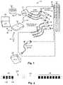
- FIG. 1is a schematic view of one embodiment of an electrical stimulation system, according to the invention.
- FIG. 2is a schematic side view of one embodiment of an electrical stimulation lead, according to the invention.
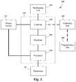
- FIG. 3is a schematic overview of one embodiment of components of a stimulation system, including an electronic subassembly disposed within a control module, according to the invention
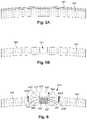
- FIG. 4Ais a schematic top view of one embodiment of a low-profile control module disposed along an outer surface of a skull and two leads extending from the control module and into the skull via burr holes formed in the skull, the burr holes covered with burr-hole covers, according to the invention;
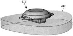
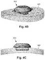
- FIG. 4Bis a schematic perspective view of one embodiment of the low-profile control module of FIG. 4A disposed along a portion of an outer surface of the skull of FIG. 4A with a portion of the control module inset into the skull, according to the invention;
- FIG. 4Cis a schematic side view of one embodiment of the low-profile control module of FIG. 4A disposed along a cross-sectional view of a portion of an outer surface of the skull of FIG. 4A with a portion of the control module inset into the skull, according to the invention;
- FIG. 5Ais a schematic cross-sectional view of a portion of a patient's head that includes a skull with a scalp disposed over an outer surface of the skull;
- FIG. 5Bis a schematic cross-sectional view of the portion of the skull shown in FIG. 5A with the overlaid scalp of FIG. 5A peeled away to expose the outer surface of the skull and a recess formed therein suitable for receiving a portion of the control module of FIGS. 4A-4C , according to the invention;
- FIG. 6is a schematic cross-sectional view of one embodiment of the control module of FIGS. 4A-4C attached to the skull of FIG. 5B with a battery of the control module disposed in a recess formed in the skull, according to the invention;
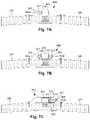
- FIG. 7Ais a schematic cross-sectional of one embodiment of the control module of FIG. 6 attached to the skull of FIG. 6 with a connector assembly disposed along one side of the electronics housing of the control module, according to the invention;
- FIG. 7Bis a schematic cross-sectional of one embodiment of the control module of FIG. 6 attached to the skull of FIG. 6 with connector assemblies disposed along opposing sides of the electronics housing of the control module, according to the invention;
- FIG. 7Cis a schematic cross-sectional of one embodiment of the control module of FIG. 6 attached to the skull of FIG. 6 with connector assemblies disposed along one side of the electronics housing of the control module, according to the invention;
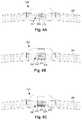
- FIG. 8Ais a schematic cross-sectional of one embodiment of the control module of FIG. 6 attached to the skull of FIG. 6 with the battery of the control module coated with silicone, according to the invention;
- FIG. 8Bis a schematic cross-sectional of one embodiment of the control module of FIG. 6 attached to the skull of FIG. 6 with the battery of the control module coated with a parylene and silicone, according to the invention.
- FIG. 8Cis a schematic cross-sectional of one embodiment of the control module of FIG. 6 attached to the skull of FIG. 6 with the battery of the control module coated with a parylene, silicone, and bone cement, according to the invention.
- the present inventionis directed to the area of implantable electrical stimulation systems and methods of making and using the systems.
- the present inventionis also directed to stimulation systems with implantable control modules utilizing a case-neutral battery, as well as making and using the battery, control modules, and electrical stimulation systems.
- Suitable implantable electrical stimulation systemsinclude, but are not limited to, a least one lead with one or more electrodes disposed on a distal portion of the lead and one or more terminals disposed on one or more proximal portions of the lead.
- Leadsinclude, for example, percutaneous leads, paddle leads, cuff leads, or any other arrangement of electrodes on a lead. Examples of electrical stimulation systems with leads are found in, for example, U.S. Pat. Nos.
- 2007/01500362009/0187222; 2009/0276021; 2010/0076535; 2010/0268298; 2011/0005069; 2011/0004267; 2011/0078900; 2011/0130817; 2011/0130818; 2011/0238129; 2011/0313500; 2012/0016378; 2012/0046710; 2012/0071949; 2012/0165911; 2012/0197375; 2012/0203316; 2012/0203320; 2012/0203321; 2012/0316615; 2013/0105071; and 2013/0197602, all of which are incorporated by reference.
- a percutaneous leadwill be exemplified, but it will be understood that the methods and systems described herein are also applicable to paddle leads and other leads.
- a percutaneous lead for electrical stimulation(for example, deep brain, spinal cord, peripheral nerve, or cardiac-tissue) includes stimulation electrodes that can be ring electrodes, segmented electrodes that extend only partially around the circumference of the lead, or any other type of electrode, or any combination thereof.
- the segmented electrodescan be provided in sets of electrodes, with each set having electrodes circumferentially distributed about the lead at a particular longitudinal position.
- a set of segmented electrodescan include any suitable number of electrodes including, for example, two, three, four, or more electrodes.
- the leadsare described herein relative to use for deep brain stimulation, but it will be understood that any of the leads can be used for applications other than deep brain stimulation, including spinal cord stimulation, peripheral nerve stimulation, dorsal root ganglion stimulation, sacral nerve stimulation, or stimulation of other nerves, muscles, and tissues.
- an electrical stimulation system 10includes one or more stimulation leads 12 and an implantable pulse generator (IPG) 14 .
- the system 10can also include one or more of an external remote control (RC) 16 , a clinician's programmer (CP) 18 , an external trial stimulator (ETS) 20 , or an external charger 22 .
- RCremote control
- CPclinician's programmer
- ETSexternal trial stimulator
- the IPG 14is physically connected, optionally, via one or more lead extensions 24 , to the stimulation lead(s) 12 .
- Each leadcarries multiple electrodes 26 arranged in an array.
- the IPG 14includes pulse generation circuitry that delivers electrical stimulation energy in the form of, for example, a pulsed electrical waveform (i.e., a temporal series of electrical pulses) to the electrode array 26 in accordance with a set of stimulation parameters.
- the implantable pulse generatorcan be implanted into a patient's body, for example, below the patient's clavicle area or within the patient's buttocks or abdominal cavity.
- the implantable pulse generatorcan have eight stimulation channels which may be independently programmable to control the magnitude of the current stimulus from each channel.
- the implantable pulse generatorcan have more or fewer than eight stimulation channels (e.g., 4-, 6-, 16-, 32-, or more stimulation channels).
- the implantable pulse generatorcan have one, two, three, four, or more connector ports, for receiving the terminals of the leads and/or lead extensions.
- the ETS 20may also be physically connected, optionally via the percutaneous lead extensions 28 and external cable 30 , to the stimulation leads 12 .
- the ETS 20which may have similar pulse generation circuitry as the IPG 14 , also delivers electrical stimulation energy in the form of, for example, a pulsed electrical waveform to the electrode array 26 in accordance with a set of stimulation parameters.
- One difference between the ETS 20 and the IPG 14is that the ETS 20 is often a non-implantable device that is used on a trial basis after the neurostimulation leads 12 have been implanted and prior to implantation of the IPG 14 , to test the responsiveness of the stimulation that is to be provided. Any functions described herein with respect to the IPG 14 can likewise be performed with respect to the ETS 20 .
- the RC 16may be used to telemetrically communicate with or control the IPG 14 or ETS 20 via a uni- or bi-directional wireless communications link 32 . Once the IPG 14 and neurostimulation leads 12 are implanted, the RC 16 may be used to telemetrically communicate with or control the IPG 14 via a uni- or bi-directional communications link 34 . Such communication or control allows the IPG 14 to be turned on or off and to be programmed with different stimulation parameter sets. The IPG 14 may also be operated to modify the programmed stimulation parameters to actively control the characteristics of the electrical stimulation energy output by the IPG 14 .
- the CP 18allows a user, such as a clinician, the ability to program stimulation parameters for the IPG 14 and ETS 20 in the operating room and in follow-up sessions. Alternately, or additionally, stimulation parameters can be programed via wireless communications (e.g., Bluetooth) between the RC 16 (or external device such as a hand-held electronic device) and the IPG 14 .
- wireless communicationse.g
- the CP 18may perform this function by indirectly communicating with the IPG 14 or ETS 20 , through the RC 16 , via a wireless communications link 36 . Alternatively, the CP 18 may directly communicate with the IPG 14 or ETS 20 via a wireless communications link (not shown).
- the stimulation parameters provided by the CP 18are also used to program the RC 16 , so that the stimulation parameters can be subsequently modified by operation of the RC 16 in a stand-alone mode (i.e., without the assistance of the CP 18 ).
- control moduleis used herein to describe a pulse generator (e.g., the IPG 14 or the ETS 20 of FIG. 1 ). Stimulation signals generated by the control module are emitted by electrodes of the lead(s) to stimulate patient tissue.
- the electrodes of the lead(s)are electrically coupled to terminals of the lead(s) that, in turn, are electrically coupleable with the control module.
- the lead(s)couple(s) directly with the control module.
- one or more intermediary devicese.g., a lead extension, an adaptor, a splitter, or the like are disposed between the lead(s) and the control module.
- Percutaneous leadsare described herein for clarity of illustration. It will be understood that paddle leads and cuff leads can be used in lieu of, or in addition to, percutaneous leads. It will be understood that the leads could include any suitable number of electrodes. It will be understood that the leads can include any suitable number of electrodes including, for example, distal-tip electrodes, or one or more segmented electrodes, and ring electrodes.
- FIG. 2illustrates one embodiment of a lead 110 with electrodes 125 disposed at least partially about a circumference of the lead 110 along a distal end portion of the lead and terminals 135 disposed along a proximal end portion of the lead.
- the lead 110can be implanted near or within the desired portion of the body to be stimulated such as, for example, the brain, spinal cord, or other body organs or tissues.
- access to the desired position in the braincan be accomplished by drilling a hole in the patient's skull or cranium with a cranial drill (commonly referred to as a burr), and coagulating and incising the dura mater, or brain covering.
- a burrcommonly referred to as a burr
- the lead 110can be inserted into the cranium and brain tissue with the assistance of a stylet (not shown).
- the lead 110can be guided to the target location within the brain using, for example, a stereotactic frame and a microdrive motor system.
- the microdrive motor systemcan be fully or partially automatic.
- the microdrive motor systemmay be configured to perform one or more the following actions (alone or in combination): insert the lead 110 , advance the lead 110 , retract the lead 110 , or rotate the lead 110 .
- measurement devices coupled to the muscles or other tissues stimulated by the target neurons, or a unit responsive to the patient or cliniciancan be coupled to the implantable pulse generator or microdrive motor system.
- the measurement device, user, or cliniciancan indicate a response by the target muscles or other tissues to the stimulation or recording electrode(s) to further identify the target neurons and facilitate positioning of the stimulation electrode(s).
- a measurement devicecan be used to observe the muscle and indicate changes in, for example, tremor frequency or amplitude in response to stimulation of neurons.
- the patient or cliniciancan observe the muscle and provide feedback.
- the lead 110 for deep brain stimulationcan include stimulation electrodes, recording electrodes, or both.
- the lead 110is rotatable so that the stimulation electrodes can be aligned with the target neurons after the neurons have been located using the recording electrodes.
- Stimulation electrodesmay be disposed on the circumference of the lead 110 to stimulate the target neurons. Stimulation electrodes may be ring-shaped so that current projects from each electrode equally in every direction from the position of the electrode along a length of the lead 110 . In the embodiment of FIG. 2 , two of the electrodes 125 are ring electrodes 120 . Ring electrodes typically do not enable stimulus current to be directed from only a limited angular range around of the lead. Segmented electrodes 130 , however, can be used to direct stimulus current to a selected angular range around the lead.
- segmented electrodesWhen segmented electrodes are used in conjunction with an implantable pulse generator that delivers constant current stimulus, current steering can be achieved to more precisely deliver the stimulus to a position around an axis of the lead (i.e., radial positioning around the axis of the lead). To achieve current steering, segmented electrodes can be utilized in addition to, or as an alternative to, ring electrodes.
- the lead 100includes a lead body 110 , terminals 135 , and one or more ring electrodes 120 and one or more sets of segmented electrodes 130 (or any other combination of electrodes).
- the lead body 110can be formed of a biocompatible, non-conducting material such as, for example, a polymeric material. Suitable polymeric materials include, but are not limited to, silicone, polyurethane, polyurea, polyurethane-urea, polyethylene, or the like.
- the lead 100may be in contact with body tissue for extended periods of time.
- the lead 100has a cross-sectional diameter of no more than 1.5 mm and may be in the range of 0.5 to 1.5 mm.
- the lead 100has a length of at least 10 cm and the length of the lead 100 may be in the range of 10 to 70 cm.
- the electrodes 125can be made using a metal, alloy, conductive oxide, or any other suitable conductive biocompatible material.
- suitable materialsinclude, but are not limited to, platinum, platinum iridium alloy, iridium, titanium, tungsten, palladium, palladium rhodium, or the like.
- the electrodesare made of a material that is biocompatible and does not substantially corrode under expected operating conditions in the operating environment for the expected duration of use.
- Each of the electrodescan either be used or unused (OFF).
- the electrodecan be used as an anode or cathode and carry anodic or cathodic current.
- an electrodemight be an anode for a period of time and a cathode for a period of time.
- Deep brain stimulation leadsmay include one or more sets of segmented electrodes. Segmented electrodes may provide for superior current steering than ring electrodes because target structures in deep brain stimulation are not typically symmetric about the axis of the distal electrode array. Instead, a target may be located on one side of a plane running through the axis of the lead.
- RSEAradially segmented electrode array
- current steeringcan be performed not only along a length of the lead but also around a circumference of the lead. This provides precise three-dimensional targeting and delivery of the current stimulus to neural target tissue, while potentially avoiding stimulation of other tissue. Examples of leads with segmented electrodes include U.S. Pat. Nos.
- Segmented electrodescan also be used for other stimulation techniques including, but not limited to, spinal cord stimulation, peripheral nerve stimulation, dorsal root ganglion stimulation, or stimulation of other nerves, muscles, and tissues.
- FIG. 3is a schematic overview of one embodiment of components of an electrical stimulation system 300 including an electronic subassembly 358 disposed within a control module.
- the electronic subassembly 358may include one or more components of the IPG. It will be understood that the electrical stimulation system can include more, fewer, or different components and can have a variety of different configurations including those configurations disclosed in the stimulator references cited herein.
- any power source 312can be used including, for example, a battery such as a primary battery or a rechargeable battery.
- Examples of other power sourcesinclude super capacitors, nuclear or atomic batteries, mechanical resonators, infrared collectors, thermally-powered energy sources, flexural powered energy sources, bioenergy power sources, fuel cells, bioelectric cells, osmotic pressure pumps, and the like including the power sources described in U.S. Pat. No. 7,437,193, incorporated herein by reference.
- powercan be supplied by an external power source through inductive coupling via the optional antenna 318 or a secondary antenna.
- the antenna 318(or the secondary antenna) is implemented using the auxiliary electrically-conductive conductor.
- the external power sourcecan be in a device that is mounted on the skin of the user or in a unit that is provided near the user on a permanent or periodic basis.
- the batterymay be recharged using the optional antenna 318 , if desired. Power can be provided to the battery for recharging by inductively coupling the battery through the antenna to a recharging unit 316 external to the user. Examples of such arrangements can be found in the references identified above.
- the electronic subassembly 358 and, optionally, the power source 312can be disposed within a control module (e.g., the IPG 14 or the ETS 20 of FIG. 1 ).
- electrical stimulation signalsare emitted by the electrodes (e.g., 26 in FIG. 1 ) to stimulate nerve fibers, muscle fibers, or other body tissues near the electrical stimulation system.
- the processor 304is generally included to control the timing and electrical characteristics of the electrical stimulation system. For example, the processor 304 can, if desired, control one or more of the timing, frequency, strength, duration, and waveform of the pulses. In addition, the processor 304 can select which electrodes can be used to provide stimulation, if desired. In some embodiments, the processor 304 selects which electrode(s) are cathodes and which electrode(s) are anodes. In some embodiments, the processor 304 is used to identify which electrodes provide the most useful stimulation of the desired tissue.
- Any processorcan be used and can be as simple as an electronic device that, for example, produces pulses at a regular interval or the processor can be capable of receiving and interpreting instructions from an external programming unit 308 that, for example, allows modification of pulse characteristics.
- the processor 304is coupled to a receiver 302 which, in turn, is coupled to the optional antenna 318 . This allows the processor 304 to receive instructions from an external source to, for example, direct the pulse characteristics and the selection of electrodes, if desired.
- the antenna 318is capable of receiving signals (e.g., RF signals) from an external telemetry unit 306 which is programmed by the programming unit 308 .
- the programming unit 308can be external to, or part of, the telemetry unit 306 .
- the telemetry unit 306can be a device that is worn on the skin of the user or can be carried by the user and can have a form similar to a pager, cellular phone, or remote control, if desired.
- the telemetry unit 306may not be worn or carried by the user but may only be available at a home station or at a clinician's office.
- the programming unit 308can be any unit that can provide information to the telemetry unit 306 for transmission to the electrical stimulation system 300 .
- the programming unit 308can be part of the telemetry unit 306 or can provide signals or information to the telemetry unit 306 via a wireless or wired connection.
- One example of a suitable programming unitis a computer operated by the user or clinician to send signals to the telemetry unit 306 .
- the signals sent to the processor 304 via the antenna 318 and the receiver 302can be used to modify or otherwise direct the operation of the electrical stimulation system.
- the signalsmay be used to modify the pulses of the electrical stimulation system such as modifying one or more of pulse duration, pulse frequency, pulse waveform, and pulse strength.
- the signalsmay also direct the electrical stimulation system 300 to cease operation, to start operation, to start charging the battery, or to stop charging the battery.
- the stimulation systemdoes not include the antenna 318 or receiver 302 and the processor 304 operates as programmed.
- the electrical stimulation system 300may include a transmitter (not shown) coupled to the processor 304 and the antenna 318 for transmitting signals back to the telemetry unit 306 or another unit capable of receiving the signals.
- the electrical stimulation system 300may transmit signals indicating whether the electrical stimulation system 300 is operating properly or not or indicating when the battery needs to be charged or the level of charge remaining in the battery.
- the processor 304may also be capable of transmitting information about the pulse characteristics so that a user or clinician can determine or verify the characteristics.
- conventional control modulesinclude electronics, connector assemblies and, in particular, power sources (e.g., batteries) that collectively create a size and shape that may limit the locations where the control module can be implanted.
- power sourcese.g., batteries
- the size or shape of a control modulemay prevent the control module from physically fitting within a desired implantation location.
- the size or shape of the control modulemay result in an undesirable cosmetic issue, such as the control module causing visible bulging of patient tissue.
- leadsare typically extended through burr holes drilled into the patient's skull.
- the control moduleis implanted below the patient's clavicle area.
- one or more leadsare tunneled along the patient's neck from the burr hole(s) to the clavicle. Forming such tunnels can be risky and undesirable for the patient.
- control modulesmay be advantageous to implant the control modules over the patient's skull and beneath the patient's scalp, thereby obviating the need to tunnel leads along the patient's neck.
- the amount of space between the patient's skull and scalpmay prevent a conventional control module from fitting over the patient's skull.
- the patientis consequently burdened with one or more unsightly bulges extending from his or her head.
- an implantable control modulemay include a rechargeable battery (e.g., power source 312 of FIG. 3 ) that is rechargeable via a charger (e.g., charger 22 of FIG. 1 ) positioned external to the patient in proximity to the battery.
- a chargere.g., charger 22 of FIG. 1
- One technique for recharging the battery of a control module when the control module is implanted in a patientincludes using a charger to inductively recharge the control module battery.
- the chargermay include a coil that generates a magnetic charging field that induces a current within a coil within the control module which, in turn, charges the control module battery.
- control module batteryIt may be advantageous to charge the control module battery as quickly as possible.
- a patient with an implanted control modulemay undergo many charging sessions over the lifespan of the implanted device. Reducing the amount of time needed to recharge the control module battery may enable patients to live a more active lifestyle and reduce inconveniences associated with regularly recharging an implanted device utilizing a battery.
- Inductively recharging the control module batterymay generate heat in the battery, thereby undesirably heating nearby patient tissue.
- the amount of heat generatedmay have a positive correlation with the rate of the recharge. In other words, increasing the charging rate of the battery may increase the amount of heat generated. Accordingly, patient safety may dictate that the charging rate of the battery be limited to the heat tolerance of patient tissue in proximity to the battery.
- the amount of heat that can be safely generated in patient tissue in proximity to the batterymay depend, at least in part, on the type of tissue in proximity to the battery.
- a control module with a case-neutral batterycan be implanted into a patient.
- Such a designmay increase the number of locations within a patient where a control module is implantable, as compared to conventional control modules.
- such a designmay also improve patient cosmetic outlooks post-implantation, by reducing undesirable bulging of patient tissue caused by the control module, as compared to conventional control modules.
- control module described hereinis used for deep brain stimulation. It will be understood, however, that a control module with a case-neutral battery can be used for applications other than deep brain stimulation, including peripheral nerve stimulation (e.g., occipital nerve stimulation, pudental nerve stimulation, or the like), spinal cord stimulation, dorsal root ganglion stimulation, sacral nerve stimulation, or stimulation of other nerves, muscles, and tissues.
- peripheral nerve stimulatione.g., occipital nerve stimulation, pudental nerve stimulation, or the like
- spinal cord stimulatione.g., dorsal root ganglion stimulation, sacral nerve stimulation, or stimulation of other nerves, muscles, and tissues.
- the control moduleis suitable for disposing over the patient's skull and beneath the patient's scalp. In at least some embodiments, when mounted to an outer surface of a patient's skull, the control module extends radially outwardly from the outer surface of the skull by no more than 10 mm, 9 mm, 8 mm, 7 mm, 6 mm, 5 mm, 4 mm, or 3 mm. In at least some embodiments, the control module extends radially outwardly from the outer surface of the skull by no less than 4 mm and no more than 7 mm. In at least some embodiments, the control module extends radially outwardly from the outer surface of the skull by no less than 5 mm and no more than 6 mm.
- control module with a case-neutral batteryreduces a height dimension of the control module, as compared to conventional control modules, at least in part by utilizing an electrically-isolated case.
- the outer surface (“case”) of the batteryis electrically coupled to either the positive or negative battery electrode. Accordingly, an additional, electrically-uncharged outer shell is typically disposed over the battery case to prevent undesired contact of the charged case with patient tissue.
- the outer shellmay be the electronics housing.
- case-neutral batteryIn contrast, the outer surface of a case-neutral battery is electrically isolated from both the positive and negative battery electrodes. Therefore, the case-neutral battery does not require an outer shell to be disposed around the battery to prevent an electrode-coupled surface of the battery from contacting patient tissue. Accordingly, the volume of a case-neutral battery may be reduced from conventional batteries without sacrificing battery capacity by removing the outer shell.
- the distance that the control module extends outwardly from the skullmay be further reduced by insetting a portion of the control module into a recess carved into the patient's skull.
- the case-neutral control moduleis configured and arranged so that the portion of the control module disposed within the recess includes the battery.
- the skullmay tolerate higher temperatures than other patient tissues (e.g., subcutaneous tissues disposed thereover).
- subcutaneous cellssuch as patient tissue disposed over the patient's skull, may become susceptible to necrosis when exposed to prolonged, elevated temperatures of 43°-45° C.
- bone cellsmay resist becoming susceptible to necrosis until exposed to prolonged, elevated temperatures of 47° C.
- bone tissuemay be able to safely tolerate temperatures 2°-4° C. higher than subcutaneous tissue.
- the batterymay be advantageous to dispose the battery within the recess of the skull to increase temperature tolerance, as compared to disposing the battery over top of the skull.
- Increased temperature tolerancemay enable the rate of charging of the battery to be safely increased from the rate of charging available when the battery of the control module is disposed over the skull.
- the skullis described as an implantation location. It will be understood, however, that the same, or similar, advantages may also be achievable in other bony structures, such as the sacrum.
- FIG. 4Ashows, in top view, one embodiment of an electrical stimulation system 410 that includes a control module 414 disposed along an outer surface of a skull 441 .
- Two leads 412 a , 412 bextend from the control module 414 and into the skull 441 via burr holes formed in the skull, over which burr hole covers 443 a , 443 b , respectively, are disposed.
- FIG. 4Bshows the control module 414 and a portion of the skull 441 in perspective view.
- FIG. 4Cshows the control module 414 (shown in side view) disposed along a portion of the skull 441 (shown in cross-sectional view).
- electrical stimulation systemscan have any suitable number of leads including, for example, one, two, three, four, five, six, seven, eight, or more leads.
- the one or more leadscan be extended through the skull via any suitable number of burr holes including, for example, one, two, three, four, five, six, seven, eight, or more burr holes.
- FIG. 5Ashows, in schematic cross-sectional view, a portion of a patient's head that includes a scalp 545 disposed over a skull 541 .
- FIG. 5Bshows, in schematic cross-sectional view, the portion of the patient's skull 541 shown in FIG. 5A .
- the scalp545 in FIG. 5A
- the recesscan be sized and shaped to accommodate a portion of the control module that includes the battery.
- FIG. 6shows, in a schematic cross-sectional view, one embodiment of the control module 414 disposed over the skull 541 .
- the control module 414includes an electronic subassembly 658 disposed in an electronics housing 651 and a case-neutral battery 612 (“battery”) external to the electronics housing 651 and coupled to the electronic subassembly 658 .
- the electronics housingis sealed. In at least some embodiments, the electronics housing is hermetically sealed. The battery abuts the electronic housing.
- the batteryincludes a positive electrode 657 and a negative electrode 659 both extending from within an electrolyte 660 disposed within a case 661 to the electronic subassembly 658 .
- the positive electrode 657 and the negative electrode 659are both electrically isolated from the case 661 .
- the caseseals the electrodes 657 , 659 from the environment external to the case; and reduces, or even eliminates, current leakage from the electrodes 657 , 659 .
- the battery casehermetically seals the electrodes 657 , 659 .
- the positive and negative electrodesare shown arranged in a side-by-side arrangement.
- the arrangement shown in FIG. 6is not meant to be limiting, as the positive and negative electrodes can be arranged relative to one another with the case in any suitable configuration.
- the positive and negative electrodesare isolated from the case and include positive and negative terminals, respectively, that electrically couple to the electronic subassembly.
- the positive and negative terminalsare formed from the same material as their respective electrodes.
- the positive and negative terminalsare formed from one or more different materials than their respective electrodes.
- one of the positive and negative terminalsis formed from the same material as their respective electrodes while the other of the positive and negative terminals is formed from one or more different materials than their respective electrodes.
- the battery case 661is open to the electronics housing 651 along a wall of the electronics housing through which the electrodes 657 , 659 extend (e.g., via feedthroughs) and to which the battery case 661 is attached.
- the battery case 661includes an optional cap 662 through which the electrodes 657 , 659 extend.
- the capis electrically isolated from the electrodes 657 , 659 and the electrodes extend through the cap via feedthroughs.
- Electrically isolating the case 661 from each of the positive and negative electrodesmay enable the height dimension 663 of the control module (i.e., how far the control module extends outwardly from the skull) to be reduced from the height dimension of conventional control modules. Electrically isolating the case 661 from each of the positive and negative electrodes obviates the need for a secondary outer shell to be disposed over the battery case, as is typically done with conventional batteries in control modules. Depending on what types of materials are used for a secondary outer shell, eliminating the secondary outer shell may enable the height dimension of the control module to be reduced by approximately 0.04-0.05 inches (0.10-0.13 cm).
- Disposing a portion of the control module in the recessmay further reduce the height dimension 657 of the control module by placing a portion of the control module beneath the outer surface 549 of the skull, thereby reducing some of the bulk of the control module disposed over the skull. It may be particularly advantageous to dispose all, or at least a majority (e.g., 50%, 60%, 70%, 80%, 90%, or more of an outer surface of the case 661 ), of the battery within the recess (as shown in FIG. 6 ). Disposing the battery of the control module in the recess may also have the advantage of enabling the charging rate of the battery to be safely increased from what a safe rate of charge for the battery would be were the battery to be disposed in subcutaneous tissue over the skull.
- a majoritye.g. 50%, 60%, 70%, 80%, 90%, or more of an outer surface of the case 661
- inductively recharging the batterymay generate heat in the battery, thereby also undesirably heating nearby patient tissue.
- the charging rate of the batterymay be limited to the heat tolerance of patient tissue in proximity to the control module. Accordingly, the amount of heat that can be safely generated in patient tissue in proximity to the control module battery may depend, at least in part, on the type of tissue heated.
- bone tissuemay be able to safely tolerate temperatures 2°-4° C. higher than subcutaneous tissue. Accordingly, it may be advantageous to dispose the battery within the recess to increase temperature tolerance, as compared to disposing the battery over top of the skull. Increased temperature tolerance, in turn, may enable the charging rate of the battery to be safely increased from the rate of charging rate of the battery were the battery disposed over the skull.
- control modulealso includes an optional covering 653 disposed over at least a portion of the control module.
- the coveringis electrically nonconductive and forms a seal to insulate electrical components from one another and/or the patient.
- the coveringcan be formed from any suitable biocompatible material.
- the coveringis formed from a thermoplastic polymer, such as polyether ether ketone.
- the coveringis made via an overmolding process.
- the coveringis disposed over the electronics housing 651 .
- the control moduleincludes a charging coil coupled to the electronic subassembly.
- the control moduleincludes one or more antennas (e.g., Bluetooth, or the like) coupled to the electronic subassembly.
- the charging coil and antenna(s)are disposed external to the electronics housing. In at least some embodiments, the charging coil and antenna(s) are disposed beneath, or embedded within, the covering.
- the control moduleis typically attached to the skull to prevent undesired migration of all, or a portion, of the control module.
- one or more fastenerse.g., screws, pins, or the like
- fasteners 655 a , 655 bare shown formed as bone screws fastened to the skull.
- the fastenerscan be extended through any suitable portion of the control module to attach the control module to the skull.
- the fastenersextend through apertures defined along opposing portions of the covering. Any suitable number of fasteners can be used to attach the control module to the skull including, for example, one, two, three, four, five, six, or more fasteners.
- control module 414may further include one or more connector assemblies coupled to the electronic subassembly.
- the connector assembliesare configured to receive one or more leads.
- the one or more leadstypically extend from the control module to a target stimulation location where stimulation generated by the control module is delivered to patient tissue.
- control moduleincludes a single connector assembly. In other embodiments, the control module includes multiple connector assemblies. In the illustrated embodiments, each connector assembly is configured and arranged to receive a single lead.
- FIGS. 7A-7Ceach shows, in schematic cross-sectional view, a different embodiment of the control module 414 disposed over the skull 541 .
- the control module 414includes a single connector assembly 765 a .
- the control moduleincludes two connector assemblies 765 a , 765 b , where the connector assemblies are disposed along opposing sides of the electronics housing 651 from one other.
- the control moduleincludes two connector assemblies 765 a , 765 b , where each of the connector assemblies is disposed along the same side of the electronics housing 651 .
- Each of the connector assembliesdefines a connector lumen 767 configured to receive a proximal portion of a lead.
- Connector contactssuch as connector contact 769 , are arranged along each of the connector lumens and are electrically coupled to the electronic subassembly via one or more connector conductors 770 .
- the connector contacts 769couple with terminals of the leads when the proximal portions of the leads are received by the connector assemblies.
- the connector contactscan be electrically isolated from one another by electrically-nonconductive spacers.
- the connector assembliesmay, optionally, include end stops to promote alignment of the lead terminals with the connector contacts.
- the covering 653is disposed over at least a portion of the one or more connector assemblies.
- the connector assembliesare disposed external to the electronics housing and the battery.
- the placement of the connector assemblies relative to the electronics housing 651can be determined based on any number of different factors including, for example, the positioning of the one or more target stimulation locations relative to the control module, the anatomy of the location where the control module is implanted, or the like. It will be understood that the number of connector assemblies and the positioning of the one or more connector assemblies relative to the electronics housing may influence the overall shape and size of the control module along one or more dimensions orthogonal to the height dimension ( 663 in FIG. 6 ).
- implantation of the control moduleincludes placement of a portion of the control module (e.g., the battery) in a recess formed in a bony structure (e.g., a skull).
- a templateis used to facilitate estimation of the recess dimensions needed to accommodate the portion of the control module to be inset into the recess.
- a molde.g., a silicone mold
- the moldcan then be used by a medical practitioner to test the dimensions of the recess during formation. Once the dimensions of the recess are sufficient for snugly fitting the mold, the mold can be removed from the recess and the control module can be implanted.
- the control moduleis positioned over the recess, with the desired portion of the control module (e.g., the battery) disposed in the recess, and the control module is fastened to the bony structure.
- the batteryis partially disposed in the recess.
- at least 50%, 60%, 70%, 80%, 90% of the batteryis disposed in the recess.
- the entire batteryis disposed in the recess.
- the portion of the control module (e.g., the battery) disposed in the recessis disposed directly against patient bone tissue (see e.g., FIG. 6 ).
- one or more layers of one or more materialsare disposed between the portion of the control module (e.g., the battery) disposed in the recess and the bone forming the walls (and floor, if applicable) of the recess.
- the one or more layers of one or more materialsare additionally disposed along other portions of the control module.
- the one or more layers of one or more materialsare disposed over the entire control module.
- FIG. 8Ashows, in a schematic cross-sectional view, one embodiment of the control module 414 disposed over the skull 541 with the battery 661 of the control module disposed in the recess 547 formed in the skull.
- the batteryis coated with a layer of silicone 871 so that the silicone is disposed between the battery and the recess when the battery is disposed in the recess.
- the siliconemay solidify over time and fill in any unreacted void spaces and reduce the risk of the patient developing an infection. It may also be advantageous to coat the entire control module with silicone, or any portion of the control module that contacts bone, including portions of the control module that are external to the recess, if applicable.
- FIG. 8Bshows, in a schematic cross-sectional view, one embodiment of the control module 414 disposed over the skull 541 with the battery 661 of the control module disposed in the recess 547 formed in the skull.
- the batteryis coated with parylene 837 and silicone 871 so that the parylene and silicone are disposed between the battery and the recess when the battery is disposed in the recess.
- Paryleneis chemically and biologically inert and has a low dielectric constant. Accordingly, it may be advantageous to coat the battery with parylene to improve one or more of the electrical, mechanical, and chemical properties of the battery.
- the one or more portions (or the entire outer surface) of the control moduleis coated with parylene.
- the control moduleis pre-coated with parylene and/or silicone prior to an implantation procedure.
- FIG. 8Cshows, in a schematic cross-sectional view, one embodiment of the control module 414 disposed over the skull 541 with the battery 661 of the control module disposed in the recess 547 formed in the skull.
- the batteryis coated with parylene 873 and silicone 871 so that the parylene and silicone are disposed between the battery and the recess when the battery is disposed in the recess.
- FIG. 8Cadditionally shows bone cement 875 disposed between the battery and the recess, in addition to parylene and silicone. In alternate embodiments, only one of parylene or silicone is disposed between the control module and the bone cement.
- the control modulemay be advantageous to coat one or more portions of the control module that abut the skull (e.g., the battery) with bone cement to facilitate attachment of the control module to the bony structure.
- the bone cementcan be used either in addition to, or in lieu of, one or more fasteners.
- the silicone and parylenecan, optionally, be broken using a tool, such as a scalpel.
Landscapes
- Health & Medical Sciences (AREA)
- Life Sciences & Earth Sciences (AREA)
- Animal Behavior & Ethology (AREA)
- Nuclear Medicine, Radiotherapy & Molecular Imaging (AREA)
- Radiology & Medical Imaging (AREA)
- Biomedical Technology (AREA)
- Engineering & Computer Science (AREA)
- General Health & Medical Sciences (AREA)
- Public Health (AREA)
- Veterinary Medicine (AREA)
- Neurology (AREA)
- Neurosurgery (AREA)
- Biophysics (AREA)
- Physiology (AREA)
- Electrotherapy Devices (AREA)
Abstract
Description
Claims (16)
Priority Applications (1)
| Application Number | Priority Date | Filing Date | Title |
|---|---|---|---|
| US16/247,447US11497914B2 (en) | 2018-01-16 | 2019-01-14 | Systems and methods for making and using an electrical stimulation system with a case-neutral battery |
Applications Claiming Priority (2)
| Application Number | Priority Date | Filing Date | Title |
|---|---|---|---|
| US201862617992P | 2018-01-16 | 2018-01-16 | |
| US16/247,447US11497914B2 (en) | 2018-01-16 | 2019-01-14 | Systems and methods for making and using an electrical stimulation system with a case-neutral battery |
Publications (2)
| Publication Number | Publication Date |
|---|---|
| US20190217102A1 US20190217102A1 (en) | 2019-07-18 |
| US11497914B2true US11497914B2 (en) | 2022-11-15 |
Family
ID=65324572
Family Applications (1)
| Application Number | Title | Priority Date | Filing Date |
|---|---|---|---|
| US16/247,447Active2040-05-27US11497914B2 (en) | 2018-01-16 | 2019-01-14 | Systems and methods for making and using an electrical stimulation system with a case-neutral battery |
Country Status (2)
| Country | Link |
|---|---|
| US (1) | US11497914B2 (en) |
| WO (1) | WO2019143574A1 (en) |
Cited By (3)
| Publication number | Priority date | Publication date | Assignee | Title |
|---|---|---|---|---|
| US20220183844A1 (en)* | 2020-12-10 | 2022-06-16 | Longeviti Neuro Solutions Llc | Cranial plug including a lucent disk |
| US12357792B2 (en) | 2019-01-04 | 2025-07-15 | Shifamed Holdings, Llc | Internal recharging systems and methods of use |
| US12440656B2 (en) | 2021-04-23 | 2025-10-14 | Shifamed Holdings, Llc | Power management for interatrial shunts and associated systems and methods |
Citations (241)
| Publication number | Priority date | Publication date | Assignee | Title |
|---|---|---|---|---|
| US979652A (en) | 1910-03-11 | 1910-12-27 | Standard Electric Fittings Company | Gas connection for outlet-boxes. |
| US2186277A (en) | 1938-11-21 | 1940-01-09 | Gen Motors Corp | Grommet seal |
| US2521301A (en) | 1950-09-05 | Morrison | ||
| US2873822A (en) | 1954-02-03 | 1959-02-17 | Cushman Chuck Co | Bolt-type locking mechanisms for indexing devices |
| US2912712A (en) | 1955-10-31 | 1959-11-17 | William S Shamban | One-piece grommet |
| US3758827A (en) | 1971-06-18 | 1973-09-11 | Philips Corp | Piezoelectric ignition device |
| US3826952A (en) | 1972-09-14 | 1974-07-30 | Rion Co | High voltage generating device |
| US3829737A (en) | 1972-07-28 | 1974-08-13 | Genoud & Cie Sa | Piezo-electric lighters |
| US4114603A (en) | 1976-08-06 | 1978-09-19 | Wilkinson Harold A | Intracranial pressure monitoring catheter |
| JPS55112538A (en) | 1979-02-23 | 1980-08-30 | Hitachi Ltd | Local overheat diagnostic unit of rotary electric machine |
| US4245645A (en) | 1977-09-28 | 1981-01-20 | Arseneault Pierre Michel | Self-locking cerebral electrical probe |
| US4297609A (en) | 1979-04-06 | 1981-10-27 | Matsushita Electric Industrial Co., Ltd. | High-voltage generating device |
| US4315180A (en) | 1976-06-10 | 1982-02-09 | Matsushita Electric Industrial Co., Ltd. | High voltage piezoelectric generating device with lengthened spark time |
| US4328313A (en) | 1979-12-19 | 1982-05-04 | The United States Of America As Represented By The Secretary Of The Navy | Method of producing a plaque dispersing enzyme |
| US4328813A (en) | 1980-10-20 | 1982-05-11 | Medtronic, Inc. | Brain lead anchoring system |
| US4467800A (en) | 1982-04-16 | 1984-08-28 | Medtronic, Inc. | Tool for creating a pocket for a epidural electrode |
| US4741571A (en) | 1986-12-15 | 1988-05-03 | Dura Corporation | Manually foldable top for automobile vehicles |
| US4805634A (en) | 1986-06-06 | 1989-02-21 | Hellige Gmbh | Adapter assembly for use with a cranial biosensor |
| US4826487A (en) | 1987-05-04 | 1989-05-02 | Victory Engineering Company | Alignment button for stereotaxic plug and method of using the same |
| US4850359A (en) | 1987-10-16 | 1989-07-25 | Ad-Tech Medical Instrument Corporation | Electrical brain-contact devices |
| US4931056A (en) | 1987-09-04 | 1990-06-05 | Neurodynamics, Inc. | Catheter guide apparatus for perpendicular insertion into a cranium orifice |
| US4955891A (en) | 1985-07-02 | 1990-09-11 | Ohio Medical Instrument Company, Inc. | Method and apparatus for performing stereotactic surgery |
| US4998938A (en) | 1988-06-09 | 1991-03-12 | Neurodynamics, Inc. | Removable skull mounted work platform and method of assembling same |
| US5116345A (en) | 1990-11-28 | 1992-05-26 | Ohio Medical Instrument Co., Inc. | Stereotactically implanting an intracranial device |
| US5193540A (en) | 1991-12-18 | 1993-03-16 | Alfred E. Mann Foundation For Scientific Research | Structure and method of manufacture of an implantable microstimulator |
| US5193539A (en) | 1991-12-18 | 1993-03-16 | Alfred E. Mann Foundation For Scientific Research | Implantable microstimulator |
| US5201737A (en) | 1991-04-11 | 1993-04-13 | Oswald Leibinger Gmbh | Plate for covering a drill hole in a skull cap and for fixing a cranial bone cover |
| US5235990A (en) | 1991-06-28 | 1993-08-17 | Dempsey Robert N | Apparatus for neutralizing irritants introduced into a body via a bite or sting |
| US5300080A (en) | 1991-11-01 | 1994-04-05 | David Clayman | Stereotactic instrument guided placement |
| US5330485A (en) | 1991-11-01 | 1994-07-19 | Clayman David A | Cerebral instrument guide frame and procedures utilizing it |
| US5464446A (en) | 1993-10-12 | 1995-11-07 | Medtronic, Inc. | Brain lead anchoring system |
| US5484445A (en) | 1993-10-12 | 1996-01-16 | Medtronic, Inc. | Sacral lead anchoring system |
| US5496356A (en) | 1993-03-29 | 1996-03-05 | Hudz; Paul H. | Piezo de-toxifier |
| US5503164A (en) | 1994-01-28 | 1996-04-02 | Osteogenics, Inc. | Device and method for repair of craniomaxillofacial bone defects including burr holes |
| US5549620A (en) | 1994-12-06 | 1996-08-27 | Bremer; Paul | Brain surgery with craniotomy pin |
| US5707373A (en) | 1996-04-26 | 1998-01-13 | Ikonos Corporation | Bone fastener and instrument for insertion thereof |
| WO1998008554A1 (en) | 1996-08-29 | 1998-03-05 | Medtronic, Inc. | Brain stimulation system having an improved anchor for a lead or catheter |
| US5732699A (en) | 1992-02-20 | 1998-03-31 | Humanteknik Ab | Device for securing an object to a surface by vacuum |
| US5776144A (en) | 1996-05-10 | 1998-07-07 | Implex Gmbh Spezialhorgerate | Device for positioning and fixing of therapeutic, surgical, or diagnostic instruments |
| US5800504A (en) | 1996-01-19 | 1998-09-01 | La Tecnica S.R.L. | Portable device for treating insect bites |
| US5843150A (en) | 1997-10-08 | 1998-12-01 | Medtronic, Inc. | System and method for providing electrical and/or fluid treatment within a patient's brain |
| US5891028A (en) | 1994-07-01 | 1999-04-06 | Humanteknik Ab | Interface element for a biomedical electrode |
| US5897531A (en) | 1994-01-07 | 1999-04-27 | Amirana; Omar | Adhesive surgical retaining device |
| EP0911061A2 (en) | 1997-10-27 | 1999-04-28 | Neuropace, Inc. | System for the treatment of neurological disorders |
| US5916154A (en) | 1998-04-22 | 1999-06-29 | Nellcor Puritan Bennett | Method of enhancing performance in pulse oximetry via electrical stimulation |
| US5927277A (en) | 1995-04-28 | 1999-07-27 | Medtronic, Inc. | Method and apparatus for securing probes within a burr hole |
| US5954687A (en) | 1995-04-28 | 1999-09-21 | Medtronic, Inc. | Burr hole ring with catheter for use as an injection port |
| WO1999055408A1 (en) | 1998-04-29 | 1999-11-04 | Medtronic, Inc. | Burr hole ring with integral lead/catheter fixation device |
| US5984930A (en) | 1996-09-30 | 1999-11-16 | George S. Allen | Biopsy guide |
| US5993463A (en) | 1997-05-15 | 1999-11-30 | Regents Of The University Of Minnesota | Remote actuation of trajectory guide |
| US6006124A (en) | 1998-05-01 | 1999-12-21 | Neuropace, Inc. | Means and method for the placement of brain electrodes |
| WO2000013743A1 (en) | 1998-09-03 | 2000-03-16 | Surgical Navigation Technologies, Inc. | Anchoring system for a brain lead |
| US6050098A (en) | 1998-04-29 | 2000-04-18 | American Standard Inc. | Use of electronic expansion valve to maintain minimum oil flow |
| US6050998A (en) | 1999-05-21 | 2000-04-18 | Stephen A. Fletcher | Bone fastener |
| US6073048A (en) | 1995-11-17 | 2000-06-06 | Medtronic, Inc. | Baroreflex modulation with carotid sinus nerve stimulation for the treatment of heart failure |
| US6094598A (en) | 1996-04-25 | 2000-07-25 | Medtronics, Inc. | Method of treating movement disorders by brain stimulation and drug infusion |
| US6117143A (en) | 1998-09-11 | 2000-09-12 | Hybex Surgical Specialties, Inc. | Apparatus for frameless stereotactic surgery |
| US6126663A (en) | 1999-04-15 | 2000-10-03 | Hair; John Hunter | Expandable bone connector |
| US6128537A (en) | 1997-05-01 | 2000-10-03 | Medtronic, Inc | Techniques for treating anxiety by brain stimulation and drug infusion |
| US6134477A (en) | 1999-04-30 | 2000-10-17 | Medtronic, Inc. | Adjustable medical lead fixation system |
| US6171239B1 (en) | 1998-08-17 | 2001-01-09 | Emory University | Systems, methods, and devices for controlling external devices by signals derived directly from the nervous system |
| US6175710B1 (en) | 1991-07-06 | 2001-01-16 | Fujitsu Limited | Electrophotographic recording apparatus using developing device with one-component type developer and having combination of charge injection effect and conductive contact type charger |
| US6181969B1 (en) | 1998-06-26 | 2001-01-30 | Advanced Bionics Corporation | Programmable current output stimulus stage for implantable device |
| US6200329B1 (en) | 1998-08-31 | 2001-03-13 | Smith & Nephew, Inc. | Suture collet |
| US6210417B1 (en) | 1999-04-29 | 2001-04-03 | Medtronic, Inc. | Medical lead positioning and anchoring system |
| US6224450B1 (en) | 1998-08-28 | 2001-05-01 | Laurie J. Norton | Cycling activity belt |
| US6230049B1 (en) | 1999-08-13 | 2001-05-08 | Neuro Pace, Inc. | Integrated system for EEG monitoring and electrical stimulation with a multiplicity of electrodes |
| US6269270B1 (en) | 1998-10-26 | 2001-07-31 | Birinder Bob Boveja | Apparatus and method for adjunct (add-on) therapy of Dementia and Alzheimer's disease utilizing an implantable lead and external stimulator |
| US6271094B1 (en) | 2000-02-14 | 2001-08-07 | International Business Machines Corporation | Method of making MOSFET with high dielectric constant gate insulator and minimum overlap capacitance |
| US6284729B1 (en) | 1996-11-06 | 2001-09-04 | Children's Medical Center Corporation | Methods and reagents for regulating obesity |
| US6295944B1 (en) | 2000-06-20 | 2001-10-02 | J Timothy Lovett | Automatic tethering system for a floating dock |
| US6321104B1 (en) | 1998-11-05 | 2001-11-20 | Medtronic, Inc. | Burr hole cap for fixation of cranial lead |
| US6324433B1 (en) | 2000-01-20 | 2001-11-27 | Electrocare Technologies, Llc | Electrode-lead coupling skull mounted port assembly |
| US20010051819A1 (en) | 1997-10-27 | 2001-12-13 | Fischell Robert E. | Implantable apparatus for treating neurological disorders |
| US20010056290A1 (en) | 1997-10-27 | 2001-12-27 | Fischell Robert E. | Methods for responsively treating neurological disorders |
| US6353762B1 (en) | 1999-04-30 | 2002-03-05 | Medtronic, Inc. | Techniques for selective activation of neurons in the brain, spinal cord parenchyma or peripheral nerve |
| US6354299B1 (en) | 1997-10-27 | 2002-03-12 | Neuropace, Inc. | Implantable device for patient communication |
| US6356729B1 (en) | 1999-04-07 | 2002-03-12 | Ricoh Company, Ltd. | Electrophotographic toner, toner container containing the toner, image forming apparatus using the toner container and method for supplying the toner from the toner container |
| US6356792B1 (en) | 2000-01-20 | 2002-03-12 | Electro Core Technologies, Llc | Skull mounted electrode lead securing assembly |
| US6356777B1 (en) | 1992-12-22 | 2002-03-12 | Schering Aktiengesellschaft | Methods of and apparatus for activating the muscle cells or nerves of the uterus or cervix |
| US6364278B1 (en) | 1999-11-05 | 2002-04-02 | Hon Hai Precision Ind. Co., Ltd. | Stand for supporting a computer |
| US6374140B1 (en) | 1998-04-30 | 2002-04-16 | Medtronic, Inc. | Method and apparatus for treating seizure disorders by stimulating the olfactory senses |
| US20020052610A1 (en) | 2000-04-07 | 2002-05-02 | Skakoon James G. | Deep organ access device and method |
| US6391985B1 (en) | 1999-10-21 | 2002-05-21 | Union Carbide Chemicals & Plastics Technology Corporation | High condensing mode polyolefin production under turbulent conditions in a fluidized bed |
| WO2002045795A2 (en) | 2000-12-07 | 2002-06-13 | Medtronic, Inc. | Directional brain stimulation and recording leads |
| US20020072770A1 (en) | 2000-04-05 | 2002-06-13 | Pless Benjamin D. | Electrical stimulation strategies to reduce the incidence of seizures |
| US6413263B1 (en) | 2000-04-24 | 2002-07-02 | Axon Instruments, Inc. | Stereotactic probe holder and method of use |
| US6427086B1 (en) | 1997-10-27 | 2002-07-30 | Neuropace, Inc. | Means and method for the intracranial placement of a neurostimulator |
| US6447443B1 (en) | 2001-01-13 | 2002-09-10 | Medtronic, Inc. | Method for organ positioning and stabilization |
| US6463328B1 (en) | 1996-02-02 | 2002-10-08 | Michael Sasha John | Adaptive brain stimulation method and system |
| US6464687B1 (en) | 1999-03-09 | 2002-10-15 | Ball Semiconductor, Inc. | Implantable drug delivery system |
| US6480743B1 (en) | 2000-04-05 | 2002-11-12 | Neuropace, Inc. | System and method for adaptive brain stimulation |
| US20020169485A1 (en) | 1995-10-16 | 2002-11-14 | Neuropace, Inc. | Differential neurostimulation therapy driven by physiological context |
| US6516227B1 (en) | 1999-07-27 | 2003-02-04 | Advanced Bionics Corporation | Rechargeable spinal cord stimulator system |
| US20030028199A1 (en) | 1998-04-14 | 2003-02-06 | Fathali Ghahremani | Slotted catheter guide for perpendicular insertion into a cranium orifice |
| WO2003026738A1 (en) | 2001-09-28 | 2003-04-03 | Northstar Neuroscience, Inc. | Methods and apparatus for electrically stimulating cells implanted in the nervous system |
| WO2003028521A2 (en) | 2001-09-30 | 2003-04-10 | Imad Younis | Electrode system for neural applications |
| US20030083724A1 (en) | 2001-10-31 | 2003-05-01 | Mandar Jog | Multichannel electrode and methods of using same |
| US6560486B1 (en) | 1999-10-12 | 2003-05-06 | Ivan Osorio | Bi-directional cerebral interface system |
| US20030088303A1 (en) | 2001-11-07 | 2003-05-08 | Goode Paul V | Multiplexed Medical device lead with standard header |
| US6571127B1 (en) | 1997-07-16 | 2003-05-27 | Impulse Dynamics N.V. | Method of increasing the motility of a GI tract |
| US6574498B1 (en) | 1999-09-16 | 2003-06-03 | Super Dimension Ltd. | Linking of an intra-body tracking system to external reference coordinates |
| US6597954B1 (en) | 1997-10-27 | 2003-07-22 | Neuropace, Inc. | System and method for controlling epileptic seizures with spatially separated detection and stimulation electrodes |
| US6609029B1 (en) | 2000-02-04 | 2003-08-19 | Advanced Bionics Corporation | Clip lock mechanism for retaining lead |
| US6609020B2 (en) | 1999-12-01 | 2003-08-19 | Steven Gill | Neurosurgical guide device |
| US6609032B1 (en) | 1999-01-07 | 2003-08-19 | Advanced Bionics Corporation | Fitting process for a neural stimulation system |
| US6618623B1 (en) | 2000-11-28 | 2003-09-09 | Neuropace, Inc. | Ferrule for cranial implant |
| US20040034367A1 (en) | 2002-08-14 | 2004-02-19 | Malinowski Zdzislaw B. | Cranial burr hole plug and insertion tool |
| US6741892B1 (en) | 2000-03-10 | 2004-05-25 | Advanced Bionics Corporation | Movable contact locking mechanism for spinal cord stimulator lead connector |
| US20040122446A1 (en) | 2002-12-20 | 2004-06-24 | Solar Matthew S. | Organ access device and method |
| US20040176673A1 (en) | 2002-12-09 | 2004-09-09 | Wahlstrand Carl D. | Concavity of an implantable medical device |
| US6795737B2 (en) | 1998-04-30 | 2004-09-21 | Medtronic Inc. | Techniques for positioning therapy delivery elements within a spinal cord or a brain |
| WO2004084749A1 (en) | 2003-03-26 | 2004-10-07 | Mrc Systems Gmbh | Device for determining the position of a target region in the brain |
| WO2004105640A2 (en) | 2003-05-29 | 2004-12-09 | The Cleveland Clinic Foundation | Excess lead retaining and management devices and methods of using same |
| US20050003268A1 (en) | 2003-05-16 | 2005-01-06 | Scott Erik R. | Battery housing configuration |
| US20050004618A1 (en) | 2003-05-16 | 2005-01-06 | Scott Erik R. | Implantable medical device with a nonhermetic battery |
| US20050010261A1 (en) | 2002-10-21 | 2005-01-13 | The Cleveland Clinic Foundation | Application of stimulus to white matter to induce a desired physiological response |
| US6845267B2 (en) | 2000-09-28 | 2005-01-18 | Advanced Bionics Corporation | Systems and methods for modulation of circulatory perfusion by electrical and/or drug stimulation |
| US6845257B2 (en) | 2000-01-27 | 2005-01-18 | Biosense Webster, Inc. | Method for mapping electrical activity |
| US20050049646A1 (en) | 2003-09-01 | 2005-03-03 | Biotronik Gmbh & Co. Kg | Intracardial impedance measuring arrangement |
| US20050070458A1 (en) | 2003-09-26 | 2005-03-31 | John Erwin R. | System and method for correction of intracerebral chemical imbalances |
| US20050075680A1 (en) | 2003-04-18 | 2005-04-07 | Lowry David Warren | Methods and systems for intracranial neurostimulation and/or sensing |
| US20050075679A1 (en) | 2002-09-30 | 2005-04-07 | Gliner Bradford E. | Methods and apparatuses for treating neurological disorders by electrically stimulating cells implanted in the nervous system |
| US20050092707A1 (en) | 2003-10-29 | 2005-05-05 | Vinit Chantalat | Method and apparatus for sealing and re-sealing an annular vessel opening |
| US20050107753A1 (en) | 2002-02-01 | 2005-05-19 | Ali Rezai | Microinfusion device |
| US6920359B2 (en) | 2000-02-15 | 2005-07-19 | Advanced Bionics Corporation | Deep brain stimulation system for the treatment of Parkinson's Disease or other disorders |
| US20050182464A1 (en) | 2004-02-13 | 2005-08-18 | Schulte Gregory T. | Methods and apparatus for securing a therapy delivery device within a burr hole |
| US6944501B1 (en) | 2000-04-05 | 2005-09-13 | Neurospace, Inc. | Neurostimulator involving stimulation strategies and process for using it |
| US6950707B2 (en) | 2000-11-21 | 2005-09-27 | Advanced Bionics Corporation | Systems and methods for treatment of obesity and eating disorders by electrical brain stimulation and/or drug infusion |
| US20050228249A1 (en) | 2004-04-09 | 2005-10-13 | Neuropace, Inc. | Implantable lead system with seed electrodes |
| US7004948B1 (en) | 2001-01-31 | 2006-02-28 | Advanced Bionics Corporation | Cranial sealing plug |
| WO2006031317A2 (en) | 2004-08-09 | 2006-03-23 | The Johns Hopkins University | Implantable mri compatible stimulation leads and antennas and related systems and methods |
| US7033326B1 (en) | 2000-12-29 | 2006-04-25 | Advanced Bionics Corporation | Systems and methods of implanting a lead for brain stimulation |
| US7050855B2 (en) | 2002-01-29 | 2006-05-23 | Medtronic, Inc. | Medical implantable system for reducing magnetic resonance effects |
| US20060129204A1 (en) | 2004-12-15 | 2006-06-15 | Neuropace, Inc. | Modulation and analysis of cerebral perfusion in epilepsy and other neurological disorders |
| US7090661B2 (en) | 2002-04-23 | 2006-08-15 | Medtronic, Inc. | Catheter anchor system and method |
| US20060190054A1 (en) | 2005-02-22 | 2006-08-24 | Malinowski Zdzislaw B | Minimally invasive systems for locating an optimal location for deep brain stimulation |
| US20060190055A1 (en) | 2005-02-22 | 2006-08-24 | Malinowski Zdzislaw B | Minimally invasive methods for locating an optimal location for deep brain stimulation |
| US7118828B2 (en) | 2002-03-11 | 2006-10-10 | Quallion Llc | Implantable battery |
| US20060229686A1 (en) | 2005-03-31 | 2006-10-12 | Medtronic, Inc. | Monopolar stimulation assembly including at least one remote electrode |
| US20060247684A1 (en) | 2001-04-13 | 2006-11-02 | Greatbatch-Sierra, Inc. | Band stop filter employing a capacitor and an inductor tank circuit to enhance mri compatibility of active medical devices |
| US7146222B2 (en) | 2002-04-15 | 2006-12-05 | Neurospace, Inc. | Reinforced sensing and stimulation leads and use in detection systems |
| US7174219B2 (en) | 2004-03-30 | 2007-02-06 | Medtronic, Inc. | Lead electrode for use in an MRI-safe implantable medical device |
| US7177701B1 (en) | 2000-12-29 | 2007-02-13 | Advanced Bionics Corporation | System for permanent electrode placement utilizing microelectrode recording methods |
| US20070106143A1 (en) | 2005-11-08 | 2007-05-10 | Flaherty J C | Electrode arrays and related methods |
| US20070150036A1 (en) | 2005-12-27 | 2007-06-28 | Advanced Bionics Corporation | Stimulator leads and methods for lead fabrication |
| US7244150B1 (en) | 2006-01-09 | 2007-07-17 | Advanced Bionics Corporation | Connector and methods of fabrication |
| US20070173844A1 (en) | 2006-01-17 | 2007-07-26 | Ralph James D | Craniotomy closures and plugs |
| US20070208352A1 (en) | 1999-04-20 | 2007-09-06 | Surgical Navigation Technologies, Inc. | Instrument Guide System |
| US20070225773A1 (en) | 2005-09-28 | 2007-09-27 | Yang Shen | Implantable transcranial pulse generator having a collapsible portion |
| US20070233195A1 (en)* | 2006-03-24 | 2007-10-04 | Medtronic, Inc. | Implantable medical device |
| US20070233158A1 (en) | 2006-04-04 | 2007-10-04 | Daniel Rodriguez | Burr hole cap and methods of use |
| US20070265683A1 (en) | 2004-09-24 | 2007-11-15 | Dov Ehrlich | Method and Apparatus for Treatment of Tinnitus and Other Neurological Disorders by Brain Stimulation in the Inferior Colliculi and/or In Adjacent Areas |
| US7343205B1 (en) | 2002-08-20 | 2008-03-11 | Boston Scientific Neuromodulation Corp. | System and method for insertion of a device into the brain |
| US20080071313A1 (en) | 2005-11-11 | 2008-03-20 | Greatbatch Ltd. | Tank filters utilizing very low k materials, in series with lead wires or circuits of active medical devices to enhance mri compatibility |
| US20080100061A1 (en) | 2006-10-30 | 2008-05-01 | Medtronic, Inc. | Breakaway connectors and systems |
| WO2008107822A1 (en) | 2007-03-02 | 2008-09-12 | Koninklijke Philips Electronics N.V. | Electrode system for deep brain stimulation |
| WO2008107815A1 (en) | 2007-03-02 | 2008-09-12 | Koninklijke Philips Electronics N.V. | Electrode system for deep brain stimulation |
| US7437193B2 (en) | 2002-06-28 | 2008-10-14 | Boston Scientific Neuromodulation Corporation | Microstimulator employing improved recharging reporting and telemetry techniques |
| US20080275466A1 (en) | 2007-05-01 | 2008-11-06 | James Grant Skakoon | Dual cannula system and method for using same |
| US20090112327A1 (en) | 2007-10-26 | 2009-04-30 | Courtney Lane | Burr hole plug designs |
| US20090118804A1 (en) | 2007-11-05 | 2009-05-07 | Advanced Bionics Corporation | Method of mounting minimally invasive plug electrodes within cranium of patient |
| US7548775B2 (en) | 2003-10-21 | 2009-06-16 | The Regents Of The University Of Michigan | Intracranial neural interface system |
| US20090157157A1 (en) | 2007-12-12 | 2009-06-18 | Schorn Greg M | Anchoring device for securing intracranial catheter or lead wire to a patient's skull |
| US20090187149A1 (en) | 2008-01-22 | 2009-07-23 | Medtronic, Inc. | Burr hole anchors, systems, and methods |
| US20090187222A1 (en) | 2008-01-23 | 2009-07-23 | Boston Scientific Neuromodulation Corporation | Steerable stylet handle assembly |
| US20090202899A1 (en) | 2008-02-11 | 2009-08-13 | Pyszczek Michael F | Electrical apparatus with integral thin film solid state battery and methods of manufacture |
| US20090246617A1 (en)* | 2008-03-28 | 2009-10-01 | Howard William G | Vanadium connector in an electrochemical cell for an implantable medical device |
| US20090276021A1 (en) | 2008-04-30 | 2009-11-05 | Boston Scientific Neuromodulation Corporation | Electrodes for stimulation leads and methods of manufacture and use |
| US20100023020A1 (en) | 2008-07-24 | 2010-01-28 | Boston Scientific Neuromodulation Corporation | Cam lock burr hole plug for securing retainer/plug base |
| US20100023100A1 (en) | 2008-07-24 | 2010-01-28 | Boston Scientific Neoromodulation Corporation | Cam lock burr hole plug for securing stimulation lead |
| US7672734B2 (en) | 2005-12-27 | 2010-03-02 | Boston Scientific Neuromodulation Corporation | Non-linear electrode array |
| US7682745B2 (en) | 2004-10-29 | 2010-03-23 | Medtronic, Inc. | Medical device having lithium-ion battery |
| US20100076535A1 (en) | 2008-09-25 | 2010-03-25 | Boston Scientific Neuromodulation Corporation | Leads with non-circular-shaped distal ends for brain stimulation systems and methods of making and using |
| US20100114249A1 (en) | 2008-10-31 | 2010-05-06 | Medtronic, Inc. | Non-hermetic direct current interconnect |
| US7756922B2 (en) | 2006-01-27 | 2010-07-13 | Oracle International Corporation | Schema annotations for managing cached document fragments |
| US7761165B1 (en) | 2005-09-29 | 2010-07-20 | Boston Scientific Neuromodulation Corporation | Implantable stimulator with integrated plastic housing/metal contacts and manufacture and use |
| US7766922B1 (en) | 2006-04-21 | 2010-08-03 | Advanced Neuromodulation Systems, Inc. | Burr hole caps and methods of use |
| US7783359B2 (en) | 2005-01-05 | 2010-08-24 | Boston Scientific Neuromodulation Corporation | Devices and methods using an implantable pulse generator for brain stimulation |
| US7787945B2 (en) | 2006-03-08 | 2010-08-31 | Neuropace, Inc. | Implantable seizure monitor |
| US7809446B2 (en) | 2005-01-05 | 2010-10-05 | Boston Scientific Neuromodulation Corporation | Devices and methods for brain stimulation |
| US20100268298A1 (en) | 2009-04-16 | 2010-10-21 | Boston Scientific Neuromodulation Corporation | Deep brain stimulation current steering with split electrodes |
| US20100280585A1 (en) | 2009-04-29 | 2010-11-04 | Medtronic, Inc. | Method and Apparatus for Securing an Electrode |
| US20100312193A1 (en) | 2007-10-08 | 2010-12-09 | Renishaw (Ireland) Limited | Neurosurgical cap |
| US20110005069A1 (en) | 2009-07-07 | 2011-01-13 | Boston Scientific Neuromodulation Corporation | Systems and leads with a radially segmented electrode array and methods of manufacture |
| US20110078900A1 (en) | 2009-07-07 | 2011-04-07 | Boston Scientific Neuromodulation Corporation | Methods for making leads with radially-aligned segmented electrodes for electrical stimulation systems |
| US7949395B2 (en) | 1999-10-01 | 2011-05-24 | Boston Scientific Neuromodulation Corporation | Implantable microdevice with extended lead and remote electrode |
| US20110130816A1 (en) | 2009-11-30 | 2011-06-02 | Boston Scientific Neuromodulation Corporation | Electrode array with electrodes having cutout portions and methods of making the same |
| US20110130803A1 (en) | 2009-11-30 | 2011-06-02 | Boston Scientific Neuromodulation Corporation | Electrode array having concentric windowed cylinder electrodes and methods of making the same |
| US20110130818A1 (en) | 2009-11-30 | 2011-06-02 | Boston Scientific Neuromodulation Corporation | Electrode array having concentric split ring electrodes and methods of making the same |
| US20110130817A1 (en) | 2009-11-30 | 2011-06-02 | Boston Scientific Neuromodulation Corporation | Electrode array having a rail system and methods of manufacturing the same |
| US7974706B2 (en) | 2006-03-30 | 2011-07-05 | Boston Scientific Neuromodulation Corporation | Electrode contact configurations for cuff leads |
| US7981119B2 (en) | 2003-12-11 | 2011-07-19 | Advanced Neuromodulation Systems, Inc. | Electrical stimulation system and associated apparatus for securing an electrical stimulation lead in position in a person's brain |
| US20110190842A1 (en)* | 2010-01-29 | 2011-08-04 | Medtronic, Inc. | Implantable medical device battery |
| US8024045B2 (en) | 2008-02-08 | 2011-09-20 | Intelect Medical, Inc. | Multi-functional burr hole assembly |
| US20110238129A1 (en) | 2010-03-23 | 2011-09-29 | Boston Scientific Neuromodulation Corporation | Helical radial spacing of contacts on a cylindrical lead |
| US20110313500A1 (en) | 2010-06-18 | 2011-12-22 | Boston Scientific Neuromodulation Corporation | Electrode array having embedded electrodes and methods of making the same |
| US20120016378A1 (en) | 2010-07-16 | 2012-01-19 | Boston Scientific Neuromodulation Corporation | Systems and methods for radial steering of electrode arrays |
| US20120046710A1 (en) | 2010-08-18 | 2012-02-23 | Boston Scientific Neuromodulation Corporation | Methods, systems, and devices for deep brain stimulation using helical movement of the centroid of stimulation |
| US20120071949A1 (en) | 2010-09-21 | 2012-03-22 | Boston Scientific Neuromodulation Corporation | Systems and methods for making and using radially-aligned segmented electrodes for leads of electrical stimulation systems |
| US8175710B2 (en) | 2006-03-14 | 2012-05-08 | Boston Scientific Neuromodulation Corporation | Stimulator system with electrode array and the method of making the same |
| US20120165911A1 (en) | 2010-12-23 | 2012-06-28 | Boston Scientific Neuromodulation Corporation | Methods for making leads with segmented electrodes for electrical stimulation systems |
| US8224450B2 (en) | 2006-09-18 | 2012-07-17 | Boston Scientific Neuromodulation Corporation | Feed through interconnect assembly for an implantable stimulation system and methods of making and using |
| US20120197375A1 (en) | 2011-02-02 | 2012-08-02 | Boston Scientific Neuromodulation Corporation | Leads with spiral of helical segmented electrode arrays and methods of making and using the leads |
| US20120203316A1 (en) | 2011-02-08 | 2012-08-09 | Boston Scientific Neuromodulation Corporation | Leads with segmented electrodes for electrical stimulation of planar regions and methods of making and using |
| US20120203321A1 (en) | 2011-02-08 | 2012-08-09 | Boston Scientific Neuromodulation Corporation | Methods for making leads with segmented electrodes for electrical stimulation systems |
| US20120203320A1 (en) | 2011-02-08 | 2012-08-09 | Boston Scientific Neuromodulation Corporation | Leads with spirally arranged segmented electrodes and methods of making and using the leads |
| US8271094B1 (en) | 2005-09-30 | 2012-09-18 | Boston Scientific Neuromodulation Corporation | Devices with cannula and electrode lead for brain stimulation and methods of use and manufacture |
| US8313453B2 (en) | 2009-08-27 | 2012-11-20 | Boston Scientific Neuromodulation Corporation | Burr hole sealing device for preventing brain shift |
| US20120316628A1 (en) | 2011-06-08 | 2012-12-13 | Lopez Thomas P | Strain relieved lead routing in burr hole plug for deep brain stimulation |
| US20120316615A1 (en) | 2011-06-07 | 2012-12-13 | Boston Scientific Neuromodulation Corporation | Systems and methods for making and using improved leads for electrical stimulation systems |
| US20130006410A1 (en) | 2009-10-30 | 2013-01-03 | Gentile Joseph P | Material Feeding Apparatus with Gripper Driving Member and Linkage |
| US8364278B2 (en) | 2002-01-29 | 2013-01-29 | Boston Scientific Neuromodulation Corporation | Lead assembly for implantable microstimulator |
| US20130066431A1 (en) | 2011-09-13 | 2013-03-14 | Jeffery V. Funderburk | Fastener holding tool for a cranial burr hole plug |
| US20130105071A1 (en) | 2011-11-02 | 2013-05-02 | Boston Scientific Neuromodulation Corporation | Systems and methods for making and using improved leads for electrical stimulation systems |
| US20130197424A1 (en) | 2006-07-31 | 2013-08-01 | Cranial Medical Systems, Inc. | Lead and methods for brain monitoring and modulation |
| US20130197602A1 (en) | 2012-01-26 | 2013-08-01 | Boston Scientific Neuromodulation Corporation | Systems and methods for identifying the circumferential positioning of electrodes of leads for electrical stimulation systems |
| US8571664B2 (en) | 2007-12-28 | 2013-10-29 | Cvrx, Inc. | Measurement of patient physiological parameters |
| US20130304216A1 (en) | 2012-05-10 | 2013-11-14 | Neuropace, Inc. | Burr Hole Covers and Methods for Using Same |
| US20140039587A1 (en) | 2012-08-03 | 2014-02-06 | Boston Scientific Neuromodulation Corporation | Leads with electrode carrier for segmented electrodes and methods of making and using |
| US8688235B1 (en) | 2008-07-22 | 2014-04-01 | Boston Scientific Neuromodulation Corporation | Lead with transition and methods of manufacture and use |
| US8792993B2 (en) | 2012-06-01 | 2014-07-29 | Boston Scientific, Neuromodulation Corporation | Leads with tip electrode for electrical stimulation systems and methods of making and using |
| US20140257325A1 (en) | 2013-03-10 | 2014-09-11 | Neuropace, Inc. | Recessed Burr Hole Covers and Methods for Using the Same |
| US20140358207A1 (en) | 2013-05-31 | 2014-12-04 | Boston Scientific Neuromodulation Corporation | Segmented electrode leads formed from pre-electrodes with depressions or apertures and methods of making and using |
| US20140358209A1 (en) | 2013-05-31 | 2014-12-04 | Boston Scientific Neuromodulation Corporation | Leads with segmented electrodes and methods of making and using the leads |
| US20140358208A1 (en) | 2013-05-31 | 2014-12-04 | Boston Scientific Neuromodulation Corporation | Segmented electrode leads formed from pre-electrodes with alignment features and methods of making and using the leads |
| US20140353001A1 (en) | 2013-05-31 | 2014-12-04 | Boston Scientific Neuromodulation Corporation | Leads containing segmented electrodes with non-perpendicular legs and methods of making and using |
| US20140358210A1 (en) | 2013-05-31 | 2014-12-04 | Boston Scientific Neuromodulation Corporation | Methods for manufacturing segmented electrode leads using a removable ring and the leads formed thereby |
| US20150018915A1 (en) | 2013-07-12 | 2015-01-15 | Boston Scientific Neuromodulation Corporation | Leads with segmented electrodes and methods of making and using the leads |
| US20150045864A1 (en) | 2013-08-07 | 2015-02-12 | Boston Scientific Neuromodulation Corporation | Systems and methods for making and using segmented tip electrodes for leads of electrical stimulation systems |
| US20150051681A1 (en) | 2013-08-19 | 2015-02-19 | Boston Scientific Neuromodulation Corporation | Methods and systems for anodal stimulation to affect cranial and other nerves |
| US20150066120A1 (en) | 2013-08-30 | 2015-03-05 | Boston Scientific Neuromodulation Corporation | Methods of making segmented electrode leads using flanged carrier |
| US20150073507A1 (en)* | 2013-09-11 | 2015-03-12 | Medtronic, Inc. | Supply noise rejection in implantable medical devices |
| US20150151113A1 (en) | 2013-12-02 | 2015-06-04 | Boston Scientific Neuromodulation Corporation | Electrical stimulation leads with helically arranged electrodes and methods of making and using |
| US9084901B2 (en) | 2006-04-28 | 2015-07-21 | Medtronic, Inc. | Cranial implant |
| US20160228692A1 (en) | 2015-02-06 | 2016-08-11 | Boston Scientific Neuromodulation Corporation | Systems and methods for making and using improved contact arrays for electrical stimulation systems |
| US9468751B2 (en) | 2012-12-05 | 2016-10-18 | Medtronic, Inc. | Medical device anchoring apparatus |
| US9492660B2 (en) | 2014-12-09 | 2016-11-15 | Pacesetter, Inc. | Implantable neurostimulation systems and methods thereof |
| US9610437B2 (en) | 2013-08-01 | 2017-04-04 | University Of Florida Research Foundation, Inc. | Apparatuses and methods for securing deep brain stimulation leads |
| US10232169B2 (en) | 2015-07-23 | 2019-03-19 | Boston Scientific Neuromodulation Corporation | Burr hole plugs for electrical stimulation systems and methods of making and using |
| US20190143125A1 (en) | 2017-11-13 | 2019-05-16 | Boston Scientific Neuromodulation Corporation | Systems and methods for making and using a low-profile control module for an electrical stimulation system |
- 2019
- 2019-01-14USUS16/247,447patent/US11497914B2/enactiveActive
- 2019-01-14WOPCT/US2019/013531patent/WO2019143574A1/ennot_activeCeased
Patent Citations (312)
| Publication number | Priority date | Publication date | Assignee | Title |
|---|---|---|---|---|
| US2521301A (en) | 1950-09-05 | Morrison | ||
| US979652A (en) | 1910-03-11 | 1910-12-27 | Standard Electric Fittings Company | Gas connection for outlet-boxes. |
| US2186277A (en) | 1938-11-21 | 1940-01-09 | Gen Motors Corp | Grommet seal |
| US2873822A (en) | 1954-02-03 | 1959-02-17 | Cushman Chuck Co | Bolt-type locking mechanisms for indexing devices |
| US2912712A (en) | 1955-10-31 | 1959-11-17 | William S Shamban | One-piece grommet |
| US3758827A (en) | 1971-06-18 | 1973-09-11 | Philips Corp | Piezoelectric ignition device |
| US3829737A (en) | 1972-07-28 | 1974-08-13 | Genoud & Cie Sa | Piezo-electric lighters |
| US3826952A (en) | 1972-09-14 | 1974-07-30 | Rion Co | High voltage generating device |
| US4315180A (en) | 1976-06-10 | 1982-02-09 | Matsushita Electric Industrial Co., Ltd. | High voltage piezoelectric generating device with lengthened spark time |
| US4114603A (en) | 1976-08-06 | 1978-09-19 | Wilkinson Harold A | Intracranial pressure monitoring catheter |
| US4245645A (en) | 1977-09-28 | 1981-01-20 | Arseneault Pierre Michel | Self-locking cerebral electrical probe |
| JPS55112538A (en) | 1979-02-23 | 1980-08-30 | Hitachi Ltd | Local overheat diagnostic unit of rotary electric machine |
| US4297609A (en) | 1979-04-06 | 1981-10-27 | Matsushita Electric Industrial Co., Ltd. | High-voltage generating device |
| US4328313A (en) | 1979-12-19 | 1982-05-04 | The United States Of America As Represented By The Secretary Of The Navy | Method of producing a plaque dispersing enzyme |
| US4328813A (en) | 1980-10-20 | 1982-05-11 | Medtronic, Inc. | Brain lead anchoring system |
| US4467800A (en) | 1982-04-16 | 1984-08-28 | Medtronic, Inc. | Tool for creating a pocket for a epidural electrode |
| US4955891A (en) | 1985-07-02 | 1990-09-11 | Ohio Medical Instrument Company, Inc. | Method and apparatus for performing stereotactic surgery |
| US4805634A (en) | 1986-06-06 | 1989-02-21 | Hellige Gmbh | Adapter assembly for use with a cranial biosensor |
| US4741571A (en) | 1986-12-15 | 1988-05-03 | Dura Corporation | Manually foldable top for automobile vehicles |
| US4826487A (en) | 1987-05-04 | 1989-05-02 | Victory Engineering Company | Alignment button for stereotaxic plug and method of using the same |
| US4931056A (en) | 1987-09-04 | 1990-06-05 | Neurodynamics, Inc. | Catheter guide apparatus for perpendicular insertion into a cranium orifice |
| US4850359A (en) | 1987-10-16 | 1989-07-25 | Ad-Tech Medical Instrument Corporation | Electrical brain-contact devices |
| US4998938A (en) | 1988-06-09 | 1991-03-12 | Neurodynamics, Inc. | Removable skull mounted work platform and method of assembling same |
| US5116345A (en) | 1990-11-28 | 1992-05-26 | Ohio Medical Instrument Co., Inc. | Stereotactically implanting an intracranial device |
| US5201737A (en) | 1991-04-11 | 1993-04-13 | Oswald Leibinger Gmbh | Plate for covering a drill hole in a skull cap and for fixing a cranial bone cover |
| US5235990A (en) | 1991-06-28 | 1993-08-17 | Dempsey Robert N | Apparatus for neutralizing irritants introduced into a body via a bite or sting |
| US6175710B1 (en) | 1991-07-06 | 2001-01-16 | Fujitsu Limited | Electrophotographic recording apparatus using developing device with one-component type developer and having combination of charge injection effect and conductive contact type charger |
| US5330485A (en) | 1991-11-01 | 1994-07-19 | Clayman David A | Cerebral instrument guide frame and procedures utilizing it |
| US5300080A (en) | 1991-11-01 | 1994-04-05 | David Clayman | Stereotactic instrument guided placement |
| US5193540A (en) | 1991-12-18 | 1993-03-16 | Alfred E. Mann Foundation For Scientific Research | Structure and method of manufacture of an implantable microstimulator |
| US5324316A (en) | 1991-12-18 | 1994-06-28 | Alfred E. Mann Foundation For Scientific Research | Implantable microstimulator |
| US5193539A (en) | 1991-12-18 | 1993-03-16 | Alfred E. Mann Foundation For Scientific Research | Implantable microstimulator |
| US5732699A (en) | 1992-02-20 | 1998-03-31 | Humanteknik Ab | Device for securing an object to a surface by vacuum |
| US6356777B1 (en) | 1992-12-22 | 2002-03-12 | Schering Aktiengesellschaft | Methods of and apparatus for activating the muscle cells or nerves of the uterus or cervix |
| US5496356A (en) | 1993-03-29 | 1996-03-05 | Hudz; Paul H. | Piezo de-toxifier |
| US5464446A (en) | 1993-10-12 | 1995-11-07 | Medtronic, Inc. | Brain lead anchoring system |
| US5484445A (en) | 1993-10-12 | 1996-01-16 | Medtronic, Inc. | Sacral lead anchoring system |
| US5897531A (en) | 1994-01-07 | 1999-04-27 | Amirana; Omar | Adhesive surgical retaining device |
| US5503164A (en) | 1994-01-28 | 1996-04-02 | Osteogenics, Inc. | Device and method for repair of craniomaxillofacial bone defects including burr holes |
| US5891028A (en) | 1994-07-01 | 1999-04-06 | Humanteknik Ab | Interface element for a biomedical electrode |
| US5549620A (en) | 1994-12-06 | 1996-08-27 | Bremer; Paul | Brain surgery with craniotomy pin |
| US5954687A (en) | 1995-04-28 | 1999-09-21 | Medtronic, Inc. | Burr hole ring with catheter for use as an injection port |
| US5927277A (en) | 1995-04-28 | 1999-07-27 | Medtronic, Inc. | Method and apparatus for securing probes within a burr hole |
| US20020169485A1 (en) | 1995-10-16 | 2002-11-14 | Neuropace, Inc. | Differential neurostimulation therapy driven by physiological context |
| US6073048A (en) | 1995-11-17 | 2000-06-06 | Medtronic, Inc. | Baroreflex modulation with carotid sinus nerve stimulation for the treatment of heart failure |
| US5800504A (en) | 1996-01-19 | 1998-09-01 | La Tecnica S.R.L. | Portable device for treating insect bites |
| US6463328B1 (en) | 1996-02-02 | 2002-10-08 | Michael Sasha John | Adaptive brain stimulation method and system |
| US6094598A (en) | 1996-04-25 | 2000-07-25 | Medtronics, Inc. | Method of treating movement disorders by brain stimulation and drug infusion |
| US5707373A (en) | 1996-04-26 | 1998-01-13 | Ikonos Corporation | Bone fastener and instrument for insertion thereof |
| US5776144A (en) | 1996-05-10 | 1998-07-07 | Implex Gmbh Spezialhorgerate | Device for positioning and fixing of therapeutic, surgical, or diagnostic instruments |
| US5865842A (en) | 1996-08-29 | 1999-02-02 | Medtronic, Inc. | System and method for anchoring brain stimulation lead or catheter |
| WO1998008554A1 (en) | 1996-08-29 | 1998-03-05 | Medtronic, Inc. | Brain stimulation system having an improved anchor for a lead or catheter |
| US5984930A (en) | 1996-09-30 | 1999-11-16 | George S. Allen | Biopsy guide |
| US6284729B1 (en) | 1996-11-06 | 2001-09-04 | Children's Medical Center Corporation | Methods and reagents for regulating obesity |
| US6128537A (en) | 1997-05-01 | 2000-10-03 | Medtronic, Inc | Techniques for treating anxiety by brain stimulation and drug infusion |
| US5993463A (en) | 1997-05-15 | 1999-11-30 | Regents Of The University Of Minnesota | Remote actuation of trajectory guide |
| US6571127B1 (en) | 1997-07-16 | 2003-05-27 | Impulse Dynamics N.V. | Method of increasing the motility of a GI tract |
| US5843150A (en) | 1997-10-08 | 1998-12-01 | Medtronic, Inc. | System and method for providing electrical and/or fluid treatment within a patient's brain |
| US6459936B2 (en) | 1997-10-27 | 2002-10-01 | Neuropace, Inc. | Methods for responsively treating neurological disorders |
| US6647296B2 (en) | 1997-10-27 | 2003-11-11 | Neuropace, Inc. | Implantable apparatus for treating neurological disorders |
| US20040153129A1 (en) | 1997-10-27 | 2004-08-05 | Neuropace, Inc. | System and method for controlling neurological disorders with spatially separated detection and therapy locations |
| US20010051819A1 (en) | 1997-10-27 | 2001-12-13 | Fischell Robert E. | Implantable apparatus for treating neurological disorders |
| US20010056290A1 (en) | 1997-10-27 | 2001-12-27 | Fischell Robert E. | Methods for responsively treating neurological disorders |
| US6128538A (en) | 1997-10-27 | 2000-10-03 | Neuropace, Inc. | Means and method for the treatment of neurological disorders |
| US6427086B1 (en) | 1997-10-27 | 2002-07-30 | Neuropace, Inc. | Means and method for the intracranial placement of a neurostimulator |
| US6134474A (en) | 1997-10-27 | 2000-10-17 | Neuropace, Inc. | Responsive implantable system for the treatment of neurological disorders |
| US20020099412A1 (en) | 1997-10-27 | 2002-07-25 | Neuropace, Inc. | Methods for using an implantable device for patient communication |
| EP0911061A2 (en) | 1997-10-27 | 1999-04-28 | Neuropace, Inc. | System for the treatment of neurological disorders |
| US6016449A (en) | 1997-10-27 | 2000-01-18 | Neuropace, Inc. | System for treatment of neurological disorders |
| US20060224216A1 (en) | 1997-10-27 | 2006-10-05 | Pless Benjamin D | System and method for controlling neurological disorders with spatially separated detection and therapy locations |
| US6597954B1 (en) | 1997-10-27 | 2003-07-22 | Neuropace, Inc. | System and method for controlling epileptic seizures with spatially separated detection and stimulation electrodes |
| US6354299B1 (en) | 1997-10-27 | 2002-03-12 | Neuropace, Inc. | Implantable device for patient communication |
| US20020002390A1 (en) | 1997-10-27 | 2002-01-03 | Fischell Robert E. | Implantable neurostimulator having a data communication link |
| US20030028199A1 (en) | 1998-04-14 | 2003-02-06 | Fathali Ghahremani | Slotted catheter guide for perpendicular insertion into a cranium orifice |
| US5916154A (en) | 1998-04-22 | 1999-06-29 | Nellcor Puritan Bennett | Method of enhancing performance in pulse oximetry via electrical stimulation |
| US6050098A (en) | 1998-04-29 | 2000-04-18 | American Standard Inc. | Use of electronic expansion valve to maintain minimum oil flow |
| US6044304A (en) | 1998-04-29 | 2000-03-28 | Medtronic, Inc. | Burr ring with integral lead/catheter fixation device |
| WO1999055408A1 (en) | 1998-04-29 | 1999-11-04 | Medtronic, Inc. | Burr hole ring with integral lead/catheter fixation device |
| US6374140B1 (en) | 1998-04-30 | 2002-04-16 | Medtronic, Inc. | Method and apparatus for treating seizure disorders by stimulating the olfactory senses |
| US6795737B2 (en) | 1998-04-30 | 2004-09-21 | Medtronic Inc. | Techniques for positioning therapy delivery elements within a spinal cord or a brain |
| US6006124A (en) | 1998-05-01 | 1999-12-21 | Neuropace, Inc. | Means and method for the placement of brain electrodes |
| US6181969B1 (en) | 1998-06-26 | 2001-01-30 | Advanced Bionics Corporation | Programmable current output stimulus stage for implantable device |
| US6171239B1 (en) | 1998-08-17 | 2001-01-09 | Emory University | Systems, methods, and devices for controlling external devices by signals derived directly from the nervous system |
| US6224450B1 (en) | 1998-08-28 | 2001-05-01 | Laurie J. Norton | Cycling activity belt |
| US6200329B1 (en) | 1998-08-31 | 2001-03-13 | Smith & Nephew, Inc. | Suture collet |
| US6482182B1 (en) | 1998-09-03 | 2002-11-19 | Surgical Navigation Technologies, Inc. | Anchoring system for a brain lead |
| WO2000013743A1 (en) | 1998-09-03 | 2000-03-16 | Surgical Navigation Technologies, Inc. | Anchoring system for a brain lead |
| US6117143A (en) | 1998-09-11 | 2000-09-12 | Hybex Surgical Specialties, Inc. | Apparatus for frameless stereotactic surgery |
| US6269270B1 (en) | 1998-10-26 | 2001-07-31 | Birinder Bob Boveja | Apparatus and method for adjunct (add-on) therapy of Dementia and Alzheimer's disease utilizing an implantable lead and external stimulator |
| US6321104B1 (en) | 1998-11-05 | 2001-11-20 | Medtronic, Inc. | Burr hole cap for fixation of cranial lead |
| US6609032B1 (en) | 1999-01-07 | 2003-08-19 | Advanced Bionics Corporation | Fitting process for a neural stimulation system |
| US6464687B1 (en) | 1999-03-09 | 2002-10-15 | Ball Semiconductor, Inc. | Implantable drug delivery system |
| US6356729B1 (en) | 1999-04-07 | 2002-03-12 | Ricoh Company, Ltd. | Electrophotographic toner, toner container containing the toner, image forming apparatus using the toner container and method for supplying the toner from the toner container |
| US6126663A (en) | 1999-04-15 | 2000-10-03 | Hair; John Hunter | Expandable bone connector |
| US20070208352A1 (en) | 1999-04-20 | 2007-09-06 | Surgical Navigation Technologies, Inc. | Instrument Guide System |
| US6210417B1 (en) | 1999-04-29 | 2001-04-03 | Medtronic, Inc. | Medical lead positioning and anchoring system |
| US6353762B1 (en) | 1999-04-30 | 2002-03-05 | Medtronic, Inc. | Techniques for selective activation of neurons in the brain, spinal cord parenchyma or peripheral nerve |
| US6134477A (en) | 1999-04-30 | 2000-10-17 | Medtronic, Inc. | Adjustable medical lead fixation system |
| US6050998A (en) | 1999-05-21 | 2000-04-18 | Stephen A. Fletcher | Bone fastener |
| US6895280B2 (en) | 1999-07-27 | 2005-05-17 | Advanced Bionics Corporation | Rechargeable spinal cord stimulator system |
| US6516227B1 (en) | 1999-07-27 | 2003-02-04 | Advanced Bionics Corporation | Rechargeable spinal cord stimulator system |
| US6230049B1 (en) | 1999-08-13 | 2001-05-08 | Neuro Pace, Inc. | Integrated system for EEG monitoring and electrical stimulation with a multiplicity of electrodes |
| US6574498B1 (en) | 1999-09-16 | 2003-06-03 | Super Dimension Ltd. | Linking of an intra-body tracking system to external reference coordinates |
| US7949395B2 (en) | 1999-10-01 | 2011-05-24 | Boston Scientific Neuromodulation Corporation | Implantable microdevice with extended lead and remote electrode |
| US6560486B1 (en) | 1999-10-12 | 2003-05-06 | Ivan Osorio | Bi-directional cerebral interface system |
| US6391985B1 (en) | 1999-10-21 | 2002-05-21 | Union Carbide Chemicals & Plastics Technology Corporation | High condensing mode polyolefin production under turbulent conditions in a fluidized bed |
| US6364278B1 (en) | 1999-11-05 | 2002-04-02 | Hon Hai Precision Ind. Co., Ltd. | Stand for supporting a computer |
| US6609020B2 (en) | 1999-12-01 | 2003-08-19 | Steven Gill | Neurosurgical guide device |
| US6356792B1 (en) | 2000-01-20 | 2002-03-12 | Electro Core Technologies, Llc | Skull mounted electrode lead securing assembly |
| US6324433B1 (en) | 2000-01-20 | 2001-11-27 | Electrocare Technologies, Llc | Electrode-lead coupling skull mounted port assembly |
| US6845257B2 (en) | 2000-01-27 | 2005-01-18 | Biosense Webster, Inc. | Method for mapping electrical activity |
| US6609029B1 (en) | 2000-02-04 | 2003-08-19 | Advanced Bionics Corporation | Clip lock mechanism for retaining lead |
| US6271094B1 (en) | 2000-02-14 | 2001-08-07 | International Business Machines Corporation | Method of making MOSFET with high dielectric constant gate insulator and minimum overlap capacitance |
| US6920359B2 (en) | 2000-02-15 | 2005-07-19 | Advanced Bionics Corporation | Deep brain stimulation system for the treatment of Parkinson's Disease or other disorders |
| US6741892B1 (en) | 2000-03-10 | 2004-05-25 | Advanced Bionics Corporation | Movable contact locking mechanism for spinal cord stimulator lead connector |
| US20020077670A1 (en) | 2000-04-05 | 2002-06-20 | Archer Stephen T. | Stimulation signal generator for an implantable device |
| US6466822B1 (en) | 2000-04-05 | 2002-10-15 | Neuropace, Inc. | Multimodal neurostimulator and process of using it |
| US6944501B1 (en) | 2000-04-05 | 2005-09-13 | Neurospace, Inc. | Neurostimulator involving stimulation strategies and process for using it |
| US20050222641A1 (en) | 2000-04-05 | 2005-10-06 | Pless Benjamin D | Neurostimulator involving stimulation strategies and process for using it |
| US20020072770A1 (en) | 2000-04-05 | 2002-06-13 | Pless Benjamin D. | Electrical stimulation strategies to reduce the incidence of seizures |
| US20060212093A1 (en) | 2000-04-05 | 2006-09-21 | Pless Benjamin D | Differential neurostimulation therapy driven by physiological therapy |
| US7174213B2 (en) | 2000-04-05 | 2007-02-06 | Pless Benjamin D | Electrical stimulation strategies to reduce the incidence of seizures |
| US6690974B2 (en) | 2000-04-05 | 2004-02-10 | Neuropace, Inc. | Stimulation signal generator for an implantable device |
| US6480743B1 (en) | 2000-04-05 | 2002-11-12 | Neuropace, Inc. | System and method for adaptive brain stimulation |
| US7815651B2 (en) | 2000-04-07 | 2010-10-19 | Medtronic, Inc. | Device for immobilizing a primary instrument and method therefor |
| US7235084B2 (en) | 2000-04-07 | 2007-06-26 | Image-Guided Neurologics, Inc. | Deep organ access device and method |
| US20020156372A1 (en) | 2000-04-07 | 2002-10-24 | Image-Guided Neurologics, Inc. | Deep organ access device and method |
| US20020052610A1 (en) | 2000-04-07 | 2002-05-02 | Skakoon James G. | Deep organ access device and method |
| US7204840B2 (en) | 2000-04-07 | 2007-04-17 | Image-Guided Neurologics, Inc. | Deep organ access device and method |
| US7833231B2 (en) | 2000-04-07 | 2010-11-16 | Medtronic, Inc. | Device for immobilizing a primary instrument and method therefor |
| US6413263B1 (en) | 2000-04-24 | 2002-07-02 | Axon Instruments, Inc. | Stereotactic probe holder and method of use |
| US6295944B1 (en) | 2000-06-20 | 2001-10-02 | J Timothy Lovett | Automatic tethering system for a floating dock |
| US6845267B2 (en) | 2000-09-28 | 2005-01-18 | Advanced Bionics Corporation | Systems and methods for modulation of circulatory perfusion by electrical and/or drug stimulation |
| US6950707B2 (en) | 2000-11-21 | 2005-09-27 | Advanced Bionics Corporation | Systems and methods for treatment of obesity and eating disorders by electrical brain stimulation and/or drug infusion |
| US6618623B1 (en) | 2000-11-28 | 2003-09-09 | Neuropace, Inc. | Ferrule for cranial implant |
| WO2002045795A2 (en) | 2000-12-07 | 2002-06-13 | Medtronic, Inc. | Directional brain stimulation and recording leads |
| US7033326B1 (en) | 2000-12-29 | 2006-04-25 | Advanced Bionics Corporation | Systems and methods of implanting a lead for brain stimulation |
| US7177701B1 (en) | 2000-12-29 | 2007-02-13 | Advanced Bionics Corporation | System for permanent electrode placement utilizing microelectrode recording methods |
| US7792590B1 (en) | 2000-12-29 | 2010-09-07 | Boston Scientific Neuromodulation Corporation | Implantable lead systems for brain stimulation |
| US7450997B1 (en) | 2000-12-29 | 2008-11-11 | Boston Scientific Neuromodulation Corporation | Method of implanting a lead for brain stimulation |
| US6447443B1 (en) | 2001-01-13 | 2002-09-10 | Medtronic, Inc. | Method for organ positioning and stabilization |
| US9101756B1 (en) | 2001-01-31 | 2015-08-11 | Boston Scientific Neuromodulation Corporation | Cranial sealing plug |
| US7004948B1 (en) | 2001-01-31 | 2006-02-28 | Advanced Bionics Corporation | Cranial sealing plug |
| US20060247684A1 (en) | 2001-04-13 | 2006-11-02 | Greatbatch-Sierra, Inc. | Band stop filter employing a capacitor and an inductor tank circuit to enhance mri compatibility of active medical devices |
| US20030088274A1 (en) | 2001-09-28 | 2003-05-08 | Vertis Neuroscience, Inc. | Method and apparatus for electrically stimulating cells implanted in the nervous system |
| WO2003026738A1 (en) | 2001-09-28 | 2003-04-03 | Northstar Neuroscience, Inc. | Methods and apparatus for electrically stimulating cells implanted in the nervous system |
| WO2003028521A2 (en) | 2001-09-30 | 2003-04-10 | Imad Younis | Electrode system for neural applications |
| US20030083724A1 (en) | 2001-10-31 | 2003-05-01 | Mandar Jog | Multichannel electrode and methods of using same |
| US20030088303A1 (en) | 2001-11-07 | 2003-05-08 | Goode Paul V | Multiplexed Medical device lead with standard header |
| US7050855B2 (en) | 2002-01-29 | 2006-05-23 | Medtronic, Inc. | Medical implantable system for reducing magnetic resonance effects |
| US8364278B2 (en) | 2002-01-29 | 2013-01-29 | Boston Scientific Neuromodulation Corporation | Lead assembly for implantable microstimulator |
| US20050107753A1 (en) | 2002-02-01 | 2005-05-19 | Ali Rezai | Microinfusion device |
| US7118828B2 (en) | 2002-03-11 | 2006-10-10 | Quallion Llc | Implantable battery |
| US7146222B2 (en) | 2002-04-15 | 2006-12-05 | Neurospace, Inc. | Reinforced sensing and stimulation leads and use in detection systems |
| US7090661B2 (en) | 2002-04-23 | 2006-08-15 | Medtronic, Inc. | Catheter anchor system and method |
| US7437193B2 (en) | 2002-06-28 | 2008-10-14 | Boston Scientific Neuromodulation Corporation | Microstimulator employing improved recharging reporting and telemetry techniques |
| US20090182351A1 (en) | 2002-08-14 | 2009-07-16 | Boston Scientific Neuromodulation Corporation | Cranial burr hold plug and insertion tool |
| US8137362B2 (en) | 2002-08-14 | 2012-03-20 | Boston Scientific Neuromodulation Corporation | Cranial burr hold plug and insertion tool |
| US20040034367A1 (en) | 2002-08-14 | 2004-02-19 | Malinowski Zdzislaw B. | Cranial burr hole plug and insertion tool |
| US7479146B2 (en) | 2002-08-14 | 2009-01-20 | Boston Scientific Neuromodulation Corporation | Cranial burr hole plug and insertion tool |
| US7343205B1 (en) | 2002-08-20 | 2008-03-11 | Boston Scientific Neuromodulation Corp. | System and method for insertion of a device into the brain |
| US20050075679A1 (en) | 2002-09-30 | 2005-04-07 | Gliner Bradford E. | Methods and apparatuses for treating neurological disorders by electrically stimulating cells implanted in the nervous system |
| US20050010261A1 (en) | 2002-10-21 | 2005-01-13 | The Cleveland Clinic Foundation | Application of stimulus to white matter to induce a desired physiological response |
| US8397732B2 (en) | 2002-12-09 | 2013-03-19 | Medtronic, Inc. | Implantation of low-profile implantable medical device |
| US20110054563A1 (en) | 2002-12-09 | 2011-03-03 | Medtronic, Inc. | Coupling module of a modular implantable medical device |
| US7242982B2 (en) | 2002-12-09 | 2007-07-10 | Medtronic, Inc. | Overmold for a modular implantable medical device |
| US20040176673A1 (en) | 2002-12-09 | 2004-09-09 | Wahlstrand Carl D. | Concavity of an implantable medical device |
| US7212864B2 (en) | 2002-12-09 | 2007-05-01 | Medtronic, Inc. | Modular implantable medical device |
| US7636596B2 (en) | 2002-12-20 | 2009-12-22 | Medtronic, Inc. | Organ access device and method |
| US20040122446A1 (en) | 2002-12-20 | 2004-06-24 | Solar Matthew S. | Organ access device and method |
| WO2004084749A1 (en) | 2003-03-26 | 2004-10-07 | Mrc Systems Gmbh | Device for determining the position of a target region in the brain |
| US20050075680A1 (en) | 2003-04-18 | 2005-04-07 | Lowry David Warren | Methods and systems for intracranial neurostimulation and/or sensing |
| US20050004618A1 (en) | 2003-05-16 | 2005-01-06 | Scott Erik R. | Implantable medical device with a nonhermetic battery |
| US20050003268A1 (en) | 2003-05-16 | 2005-01-06 | Scott Erik R. | Battery housing configuration |
| US7454251B2 (en) | 2003-05-29 | 2008-11-18 | The Cleveland Clinic Foundation | Excess lead retaining and management devices and methods of using same |
| WO2004105640A2 (en) | 2003-05-29 | 2004-12-09 | The Cleveland Clinic Foundation | Excess lead retaining and management devices and methods of using same |
| US20050015128A1 (en) | 2003-05-29 | 2005-01-20 | Rezai Ali R. | Excess lead retaining and management devices and methods of using same |
| US20050049646A1 (en) | 2003-09-01 | 2005-03-03 | Biotronik Gmbh & Co. Kg | Intracardial impedance measuring arrangement |
| US20050070458A1 (en) | 2003-09-26 | 2005-03-31 | John Erwin R. | System and method for correction of intracerebral chemical imbalances |
| US7548775B2 (en) | 2003-10-21 | 2009-06-16 | The Regents Of The University Of Michigan | Intracranial neural interface system |
| US20050092707A1 (en) | 2003-10-29 | 2005-05-05 | Vinit Chantalat | Method and apparatus for sealing and re-sealing an annular vessel opening |
| US7981119B2 (en) | 2003-12-11 | 2011-07-19 | Advanced Neuromodulation Systems, Inc. | Electrical stimulation system and associated apparatus for securing an electrical stimulation lead in position in a person's brain |
| WO2005079903A2 (en) | 2004-02-13 | 2005-09-01 | Medtronic, Inc. | Methods and apparatus for securing a therapy delivery device within a burr hole |
| US20050182423A1 (en) | 2004-02-13 | 2005-08-18 | Schulte Gregory T. | Methods and apparatus for securing a therapy delivery device within a burr hole |
| US20050182422A1 (en) | 2004-02-13 | 2005-08-18 | Schulte Gregory T. | Apparatus for securing a therapy delivery device within a burr hole and method for making same |
| US20050182421A1 (en) | 2004-02-13 | 2005-08-18 | Schulte Gregory T. | Methods and apparatus for securing a therapy delivery device within a burr hole |
| US20050182424A1 (en) | 2004-02-13 | 2005-08-18 | Schulte Gregory T. | Methods and apparatus for securing a therapy delivery device within a burr hole |
| US20050182425A1 (en) | 2004-02-13 | 2005-08-18 | Schulte Gregory T. | Methods and apparatus for securing a therapy delivery device within a burr hole |
| US20050182464A1 (en) | 2004-02-13 | 2005-08-18 | Schulte Gregory T. | Methods and apparatus for securing a therapy delivery device within a burr hole |
| US7174219B2 (en) | 2004-03-30 | 2007-02-06 | Medtronic, Inc. | Lead electrode for use in an MRI-safe implantable medical device |
| US20050228249A1 (en) | 2004-04-09 | 2005-10-13 | Neuropace, Inc. | Implantable lead system with seed electrodes |
| WO2006031317A2 (en) | 2004-08-09 | 2006-03-23 | The Johns Hopkins University | Implantable mri compatible stimulation leads and antennas and related systems and methods |
| US20070265683A1 (en) | 2004-09-24 | 2007-11-15 | Dov Ehrlich | Method and Apparatus for Treatment of Tinnitus and Other Neurological Disorders by Brain Stimulation in the Inferior Colliculi and/or In Adjacent Areas |
| US7682745B2 (en) | 2004-10-29 | 2010-03-23 | Medtronic, Inc. | Medical device having lithium-ion battery |
| US20060129204A1 (en) | 2004-12-15 | 2006-06-15 | Neuropace, Inc. | Modulation and analysis of cerebral perfusion in epilepsy and other neurological disorders |
| US20110004267A1 (en) | 2005-01-05 | 2011-01-06 | Boston Scientific Neuromodulation Corporation | Devices and methods for brain stimulation |
| US7809446B2 (en) | 2005-01-05 | 2010-10-05 | Boston Scientific Neuromodulation Corporation | Devices and methods for brain stimulation |
| US7783359B2 (en) | 2005-01-05 | 2010-08-24 | Boston Scientific Neuromodulation Corporation | Devices and methods using an implantable pulse generator for brain stimulation |
| US20060190054A1 (en) | 2005-02-22 | 2006-08-24 | Malinowski Zdzislaw B | Minimally invasive systems for locating an optimal location for deep brain stimulation |
| US20060190055A1 (en) | 2005-02-22 | 2006-08-24 | Malinowski Zdzislaw B | Minimally invasive methods for locating an optimal location for deep brain stimulation |
| US7369899B2 (en) | 2005-02-22 | 2008-05-06 | Boston Scientific Neuromodulation Corporation | Minimally invasive systems for locating an optimal location for deep brain stimulation |
| US20080243219A1 (en) | 2005-02-22 | 2008-10-02 | Boston Scientific Neuromodulation Corporation | Minimally invasive systems for locating an optimal location for deep brain stimulation |
| US7421297B2 (en) | 2005-03-31 | 2008-09-02 | Medtronic, Inc. | Monopolar stimulation assembly including at least one remote electrode |
| US20060229686A1 (en) | 2005-03-31 | 2006-10-12 | Medtronic, Inc. | Monopolar stimulation assembly including at least one remote electrode |
| US20070225773A1 (en) | 2005-09-28 | 2007-09-27 | Yang Shen | Implantable transcranial pulse generator having a collapsible portion |
| US7761165B1 (en) | 2005-09-29 | 2010-07-20 | Boston Scientific Neuromodulation Corporation | Implantable stimulator with integrated plastic housing/metal contacts and manufacture and use |
| US8271094B1 (en) | 2005-09-30 | 2012-09-18 | Boston Scientific Neuromodulation Corporation | Devices with cannula and electrode lead for brain stimulation and methods of use and manufacture |
| US20070106143A1 (en) | 2005-11-08 | 2007-05-10 | Flaherty J C | Electrode arrays and related methods |
| US20080071313A1 (en) | 2005-11-11 | 2008-03-20 | Greatbatch Ltd. | Tank filters utilizing very low k materials, in series with lead wires or circuits of active medical devices to enhance mri compatibility |
| US20070150036A1 (en) | 2005-12-27 | 2007-06-28 | Advanced Bionics Corporation | Stimulator leads and methods for lead fabrication |
| US7672734B2 (en) | 2005-12-27 | 2010-03-02 | Boston Scientific Neuromodulation Corporation | Non-linear electrode array |
| US7244150B1 (en) | 2006-01-09 | 2007-07-17 | Advanced Bionics Corporation | Connector and methods of fabrication |
| US20070173844A1 (en) | 2006-01-17 | 2007-07-26 | Ralph James D | Craniotomy closures and plugs |
| US7833253B2 (en) | 2006-01-17 | 2010-11-16 | Biodynamics Llc | Craniotomy closures and plugs |
| US7756922B2 (en) | 2006-01-27 | 2010-07-13 | Oracle International Corporation | Schema annotations for managing cached document fragments |
| US7787945B2 (en) | 2006-03-08 | 2010-08-31 | Neuropace, Inc. | Implantable seizure monitor |
| US8175710B2 (en) | 2006-03-14 | 2012-05-08 | Boston Scientific Neuromodulation Corporation | Stimulator system with electrode array and the method of making the same |
| US20070233195A1 (en)* | 2006-03-24 | 2007-10-04 | Medtronic, Inc. | Implantable medical device |
| US7974706B2 (en) | 2006-03-30 | 2011-07-05 | Boston Scientific Neuromodulation Corporation | Electrode contact configurations for cuff leads |
| US7949410B2 (en) | 2006-04-04 | 2011-05-24 | Advanced Neuromodulation Systems, Inc. | Burr hole cap and methods of use |
| US20070233158A1 (en) | 2006-04-04 | 2007-10-04 | Daniel Rodriguez | Burr hole cap and methods of use |
| US7766922B1 (en) | 2006-04-21 | 2010-08-03 | Advanced Neuromodulation Systems, Inc. | Burr hole caps and methods of use |
| US9084901B2 (en) | 2006-04-28 | 2015-07-21 | Medtronic, Inc. | Cranial implant |
| US20130197424A1 (en) | 2006-07-31 | 2013-08-01 | Cranial Medical Systems, Inc. | Lead and methods for brain monitoring and modulation |
| US8224450B2 (en) | 2006-09-18 | 2012-07-17 | Boston Scientific Neuromodulation Corporation | Feed through interconnect assembly for an implantable stimulation system and methods of making and using |
| US20080100061A1 (en) | 2006-10-30 | 2008-05-01 | Medtronic, Inc. | Breakaway connectors and systems |
| US20080172068A1 (en) | 2006-10-30 | 2008-07-17 | Adams Matthew H | Externally releasable body portal anchors and systems |
| WO2008054699A2 (en) | 2006-10-30 | 2008-05-08 | Medtronic, Inc | Breakaway connectors and systems |
| WO2008054691A2 (en) | 2006-10-30 | 2008-05-08 | Medtronic, Inc. | Externally releasable body portal anchors and systems |
| WO2008107822A1 (en) | 2007-03-02 | 2008-09-12 | Koninklijke Philips Electronics N.V. | Electrode system for deep brain stimulation |
| WO2008107815A1 (en) | 2007-03-02 | 2008-09-12 | Koninklijke Philips Electronics N.V. | Electrode system for deep brain stimulation |
| WO2008134509A1 (en) | 2007-05-01 | 2008-11-06 | Medtronic, Inc. | Dual cannula system and method for using same |
| US20080275466A1 (en) | 2007-05-01 | 2008-11-06 | James Grant Skakoon | Dual cannula system and method for using same |
| US20100312193A1 (en) | 2007-10-08 | 2010-12-09 | Renishaw (Ireland) Limited | Neurosurgical cap |
| US20090112327A1 (en) | 2007-10-26 | 2009-04-30 | Courtney Lane | Burr hole plug designs |
| US9043000B2 (en) | 2007-10-26 | 2015-05-26 | Boston Scientific Neuromodulation Corporation | Burr hole plug having sidable clamping mechanism |
| WO2009055746A2 (en) | 2007-10-26 | 2009-04-30 | Boston Scientific Neuromodulation Corporation | Burr hole plug designs |
| US20100145357A1 (en) | 2007-10-26 | 2010-06-10 | Boston Scientific Neuromodulation Corporation | Burr hole plug having dual slidable clamping mechanisms |
| US8731686B2 (en) | 2007-10-26 | 2014-05-20 | Boston Scientific Neuromodulation Corporation | Burr hole plug having dual slidable clamping mechanisms |
| US20090118804A1 (en) | 2007-11-05 | 2009-05-07 | Advanced Bionics Corporation | Method of mounting minimally invasive plug electrodes within cranium of patient |
| US20090157157A1 (en) | 2007-12-12 | 2009-06-18 | Schorn Greg M | Anchoring device for securing intracranial catheter or lead wire to a patient's skull |
| US8571664B2 (en) | 2007-12-28 | 2013-10-29 | Cvrx, Inc. | Measurement of patient physiological parameters |
| US20090187149A1 (en) | 2008-01-22 | 2009-07-23 | Medtronic, Inc. | Burr hole anchors, systems, and methods |
| US20090187222A1 (en) | 2008-01-23 | 2009-07-23 | Boston Scientific Neuromodulation Corporation | Steerable stylet handle assembly |
| US8024045B2 (en) | 2008-02-08 | 2011-09-20 | Intelect Medical, Inc. | Multi-functional burr hole assembly |
| US20090202899A1 (en) | 2008-02-11 | 2009-08-13 | Pyszczek Michael F | Electrical apparatus with integral thin film solid state battery and methods of manufacture |
| US20090246617A1 (en)* | 2008-03-28 | 2009-10-01 | Howard William G | Vanadium connector in an electrochemical cell for an implantable medical device |
| US20090276021A1 (en) | 2008-04-30 | 2009-11-05 | Boston Scientific Neuromodulation Corporation | Electrodes for stimulation leads and methods of manufacture and use |
| US8688235B1 (en) | 2008-07-22 | 2014-04-01 | Boston Scientific Neuromodulation Corporation | Lead with transition and methods of manufacture and use |
| US8764767B2 (en) | 2008-07-24 | 2014-07-01 | Boston Scientific Neuromodulation Corporation | Cam lock burr hole plug for securing stimulation lead |
| US8425534B2 (en) | 2008-07-24 | 2013-04-23 | Boston Scientific Neuromodulation Corporation | Cam lock burr hole plug for securing stimulation lead |
| US20100023100A1 (en) | 2008-07-24 | 2010-01-28 | Boston Scientific Neoromodulation Corporation | Cam lock burr hole plug for securing stimulation lead |
| US8043304B2 (en) | 2008-07-24 | 2011-10-25 | Boston Scientific Neuromodulation Corporation | Cam lock burr hole plug for securing retainer/plug base |
| US20100023020A1 (en) | 2008-07-24 | 2010-01-28 | Boston Scientific Neuromodulation Corporation | Cam lock burr hole plug for securing retainer/plug base |
| US20100076535A1 (en) | 2008-09-25 | 2010-03-25 | Boston Scientific Neuromodulation Corporation | Leads with non-circular-shaped distal ends for brain stimulation systems and methods of making and using |
| US20100114249A1 (en) | 2008-10-31 | 2010-05-06 | Medtronic, Inc. | Non-hermetic direct current interconnect |
| US20100268298A1 (en) | 2009-04-16 | 2010-10-21 | Boston Scientific Neuromodulation Corporation | Deep brain stimulation current steering with split electrodes |
| US8473061B2 (en) | 2009-04-16 | 2013-06-25 | Boston Scientific Neuromodulation Corporation | Deep brain stimulation current steering with split electrodes |
| US20100280585A1 (en) | 2009-04-29 | 2010-11-04 | Medtronic, Inc. | Method and Apparatus for Securing an Electrode |
| US20110005069A1 (en) | 2009-07-07 | 2011-01-13 | Boston Scientific Neuromodulation Corporation | Systems and leads with a radially segmented electrode array and methods of manufacture |
| US20110078900A1 (en) | 2009-07-07 | 2011-04-07 | Boston Scientific Neuromodulation Corporation | Methods for making leads with radially-aligned segmented electrodes for electrical stimulation systems |
| US8313453B2 (en) | 2009-08-27 | 2012-11-20 | Boston Scientific Neuromodulation Corporation | Burr hole sealing device for preventing brain shift |
| US20130006410A1 (en) | 2009-10-30 | 2013-01-03 | Gentile Joseph P | Material Feeding Apparatus with Gripper Driving Member and Linkage |
| US20110130816A1 (en) | 2009-11-30 | 2011-06-02 | Boston Scientific Neuromodulation Corporation | Electrode array with electrodes having cutout portions and methods of making the same |
| US8295944B2 (en) | 2009-11-30 | 2012-10-23 | Boston Scientific Neuromodulation Corporation | Electrode array with electrodes having cutout portions and methods of making the same |
| US20110130817A1 (en) | 2009-11-30 | 2011-06-02 | Boston Scientific Neuromodulation Corporation | Electrode array having a rail system and methods of manufacturing the same |
| US20110130803A1 (en) | 2009-11-30 | 2011-06-02 | Boston Scientific Neuromodulation Corporation | Electrode array having concentric windowed cylinder electrodes and methods of making the same |
| US20110130818A1 (en) | 2009-11-30 | 2011-06-02 | Boston Scientific Neuromodulation Corporation | Electrode array having concentric split ring electrodes and methods of making the same |
| US8391985B2 (en) | 2009-11-30 | 2013-03-05 | Boston Scientific Neuromodulation Corporation | Electrode array having concentric windowed cylinder electrodes and methods of making the same |
| US20110190842A1 (en)* | 2010-01-29 | 2011-08-04 | Medtronic, Inc. | Implantable medical device battery |
| US8571665B2 (en) | 2010-03-23 | 2013-10-29 | Boston Scientific Neuromodulation Corporation | Helical radial spacing of contacts on a cylindrical lead |
| US20110238129A1 (en) | 2010-03-23 | 2011-09-29 | Boston Scientific Neuromodulation Corporation | Helical radial spacing of contacts on a cylindrical lead |
| US20110313500A1 (en) | 2010-06-18 | 2011-12-22 | Boston Scientific Neuromodulation Corporation | Electrode array having embedded electrodes and methods of making the same |
| US20120016378A1 (en) | 2010-07-16 | 2012-01-19 | Boston Scientific Neuromodulation Corporation | Systems and methods for radial steering of electrode arrays |
| US20120046710A1 (en) | 2010-08-18 | 2012-02-23 | Boston Scientific Neuromodulation Corporation | Methods, systems, and devices for deep brain stimulation using helical movement of the centroid of stimulation |
| US20120071949A1 (en) | 2010-09-21 | 2012-03-22 | Boston Scientific Neuromodulation Corporation | Systems and methods for making and using radially-aligned segmented electrodes for leads of electrical stimulation systems |
| US20120165911A1 (en) | 2010-12-23 | 2012-06-28 | Boston Scientific Neuromodulation Corporation | Methods for making leads with segmented electrodes for electrical stimulation systems |
| US20120197375A1 (en) | 2011-02-02 | 2012-08-02 | Boston Scientific Neuromodulation Corporation | Leads with spiral of helical segmented electrode arrays and methods of making and using the leads |
| US20120203320A1 (en) | 2011-02-08 | 2012-08-09 | Boston Scientific Neuromodulation Corporation | Leads with spirally arranged segmented electrodes and methods of making and using the leads |
| US20120203321A1 (en) | 2011-02-08 | 2012-08-09 | Boston Scientific Neuromodulation Corporation | Methods for making leads with segmented electrodes for electrical stimulation systems |
| US20120203316A1 (en) | 2011-02-08 | 2012-08-09 | Boston Scientific Neuromodulation Corporation | Leads with segmented electrodes for electrical stimulation of planar regions and methods of making and using |
| US20120316615A1 (en) | 2011-06-07 | 2012-12-13 | Boston Scientific Neuromodulation Corporation | Systems and methods for making and using improved leads for electrical stimulation systems |
| US20120316628A1 (en) | 2011-06-08 | 2012-12-13 | Lopez Thomas P | Strain relieved lead routing in burr hole plug for deep brain stimulation |
| US9474896B2 (en) | 2011-06-08 | 2016-10-25 | Boston Scientific Neuromodulation Corporation | Strain relieved lead routing in burr hole plug for deep brain stimulation |
| US9050191B2 (en) | 2011-09-13 | 2015-06-09 | Boston Scientific Neuromodulation Corporation | Cranial burr hole plug with adaptable mounting surface |
| US20130066431A1 (en) | 2011-09-13 | 2013-03-14 | Jeffery V. Funderburk | Fastener holding tool for a cranial burr hole plug |
| US8812133B2 (en) | 2011-09-13 | 2014-08-19 | Boston Scientific Neuromodulation Corporation | Cranial burr hole plug with anti-skewing clamping mechanism |
| US20130066430A1 (en) | 2011-09-13 | 2013-03-14 | Jeffery V. Funderburk | Cranial burr hole plug with adaptable mounting surface |
| US20130105071A1 (en) | 2011-11-02 | 2013-05-02 | Boston Scientific Neuromodulation Corporation | Systems and methods for making and using improved leads for electrical stimulation systems |
| US20130197602A1 (en) | 2012-01-26 | 2013-08-01 | Boston Scientific Neuromodulation Corporation | Systems and methods for identifying the circumferential positioning of electrodes of leads for electrical stimulation systems |
| US20130304216A1 (en) | 2012-05-10 | 2013-11-14 | Neuropace, Inc. | Burr Hole Covers and Methods for Using Same |
| US8792993B2 (en) | 2012-06-01 | 2014-07-29 | Boston Scientific, Neuromodulation Corporation | Leads with tip electrode for electrical stimulation systems and methods of making and using |
| US20140039587A1 (en) | 2012-08-03 | 2014-02-06 | Boston Scientific Neuromodulation Corporation | Leads with electrode carrier for segmented electrodes and methods of making and using |
| US9604052B2 (en) | 2012-12-05 | 2017-03-28 | Medtronic, Inc. | Medical device anchoring apparatus and methods |
| US9468751B2 (en) | 2012-12-05 | 2016-10-18 | Medtronic, Inc. | Medical device anchoring apparatus |
| US20140257325A1 (en) | 2013-03-10 | 2014-09-11 | Neuropace, Inc. | Recessed Burr Hole Covers and Methods for Using the Same |
| US20140358208A1 (en) | 2013-05-31 | 2014-12-04 | Boston Scientific Neuromodulation Corporation | Segmented electrode leads formed from pre-electrodes with alignment features and methods of making and using the leads |
| US20140358209A1 (en) | 2013-05-31 | 2014-12-04 | Boston Scientific Neuromodulation Corporation | Leads with segmented electrodes and methods of making and using the leads |
| US20140358207A1 (en) | 2013-05-31 | 2014-12-04 | Boston Scientific Neuromodulation Corporation | Segmented electrode leads formed from pre-electrodes with depressions or apertures and methods of making and using |
| US20140353001A1 (en) | 2013-05-31 | 2014-12-04 | Boston Scientific Neuromodulation Corporation | Leads containing segmented electrodes with non-perpendicular legs and methods of making and using |
| US20140358210A1 (en) | 2013-05-31 | 2014-12-04 | Boston Scientific Neuromodulation Corporation | Methods for manufacturing segmented electrode leads using a removable ring and the leads formed thereby |
| US20150018915A1 (en) | 2013-07-12 | 2015-01-15 | Boston Scientific Neuromodulation Corporation | Leads with segmented electrodes and methods of making and using the leads |
| US9610437B2 (en) | 2013-08-01 | 2017-04-04 | University Of Florida Research Foundation, Inc. | Apparatuses and methods for securing deep brain stimulation leads |
| US20150045864A1 (en) | 2013-08-07 | 2015-02-12 | Boston Scientific Neuromodulation Corporation | Systems and methods for making and using segmented tip electrodes for leads of electrical stimulation systems |
| US20150051681A1 (en) | 2013-08-19 | 2015-02-19 | Boston Scientific Neuromodulation Corporation | Methods and systems for anodal stimulation to affect cranial and other nerves |
| US20150066120A1 (en) | 2013-08-30 | 2015-03-05 | Boston Scientific Neuromodulation Corporation | Methods of making segmented electrode leads using flanged carrier |
| US20150073507A1 (en)* | 2013-09-11 | 2015-03-12 | Medtronic, Inc. | Supply noise rejection in implantable medical devices |
| US20150151113A1 (en) | 2013-12-02 | 2015-06-04 | Boston Scientific Neuromodulation Corporation | Electrical stimulation leads with helically arranged electrodes and methods of making and using |
| US9492660B2 (en) | 2014-12-09 | 2016-11-15 | Pacesetter, Inc. | Implantable neurostimulation systems and methods thereof |
| US20160228692A1 (en) | 2015-02-06 | 2016-08-11 | Boston Scientific Neuromodulation Corporation | Systems and methods for making and using improved contact arrays for electrical stimulation systems |
| US10232169B2 (en) | 2015-07-23 | 2019-03-19 | Boston Scientific Neuromodulation Corporation | Burr hole plugs for electrical stimulation systems and methods of making and using |
| US20190143125A1 (en) | 2017-11-13 | 2019-05-16 | Boston Scientific Neuromodulation Corporation | Systems and methods for making and using a low-profile control module for an electrical stimulation system |
Non-Patent Citations (7)
| Title |
|---|
| Axelsson, Stefan et ai., Longitudinal cephalometric standards for the neurocranium in Norwegians from 6 to 21 years of age, European Journal of Orthodontics, vol. 25 (2003) pp. 185-198. |
| Dickhaus H., Ganser KA, Stuabert A., Bonsanto MM, Wirtz CR, Tronnier VM, Kunze S: Quantification of brain shift effects by MR-imaging. Engineering in Medicine and Biology Society vol. 2: 491-494, 1997. |
| International Search Report and Written Opinion for PCT Application No. PCT/US2019/013531 dated Apr. 1, 2019. |
| Lieberman, Daniel E. et al., Basicranial influence on overall cranial shape, Journal of Human Evolution, vol. 38 (2000) pp. 291-315. |
| Nimsky C., Gansland 0., Cerny S., Hastreiter P, Greiner G., Fahlbusch R.: Quantification of, visualization of, and compensation for brain shift using intraoperative magnetic resonance imaging. Neurosurgery 47, 1070-1080, 2000. |
| Roberts DW, Hartov A. Kennedy FE, Miga MI, Paulsen KD: Intraoperative brain shift and deformation: A quantitative analysis of cortical displacement in 28 cases. Neurosurgery 43:749-760, 1998. |
| Winkler D., Tittgemeyer M., Schwartz J., Preul C., Strecker K., Meixensberger J.: The first evaluation of brain shift during functional neurosurgery by deformation field analysis. Journal of Neurology, Neurosurgery, and Psychiatry 76 (8): 1161-3, 2005. |
Cited By (4)
| Publication number | Priority date | Publication date | Assignee | Title |
|---|---|---|---|---|
| US12357792B2 (en) | 2019-01-04 | 2025-07-15 | Shifamed Holdings, Llc | Internal recharging systems and methods of use |
| US20220183844A1 (en)* | 2020-12-10 | 2022-06-16 | Longeviti Neuro Solutions Llc | Cranial plug including a lucent disk |
| US12383402B2 (en)* | 2020-12-10 | 2025-08-12 | Longeviti Neuro Solutions, Inc. | Cranial plug including a lucent disk |
| US12440656B2 (en) | 2021-04-23 | 2025-10-14 | Shifamed Holdings, Llc | Power management for interatrial shunts and associated systems and methods |
Also Published As
| Publication number | Publication date |
|---|---|
| US20190217102A1 (en) | 2019-07-18 |
| WO2019143574A1 (en) | 2019-07-25 |
Similar Documents
| Publication | Publication Date | Title |
|---|---|---|
| US9616220B2 (en) | Systems and methods for making and using tip electrodes for leads of electrical stimulation systems | |
| US11103716B2 (en) | Systems and methods for making and using a low-profile control module for an electrical stimulation system | |
| US10286205B2 (en) | Systems and methods for making and using improved contact arrays for electrical stimulation systems | |
| US20180369596A1 (en) | Systems and methods for providing an auxiliary electrical connection along an electrical stimulation system | |
| US20130317587A1 (en) | Methods for stimulating the dorsal root ganglion with a lead having segmented electrodes | |
| EP3790623B1 (en) | Connector assembly for an electrical stimulation system | |
| US20190290924A1 (en) | Implantable prostheses for reducing visibility of bulging from implanted medical devices | |
| US11013913B2 (en) | Kits and methods for securing a burr hole plugs for stimulation systems | |
| US12343547B2 (en) | Connectors for an electrical stimulation system and methods of making and using | |
| US11497914B2 (en) | Systems and methods for making and using an electrical stimulation system with a case-neutral battery | |
| US11058870B2 (en) | Burr hole plugs for electrical stimulation systems and methods of making and using | |
| EP3946569B1 (en) | Low-profile control module for an electrical stimulation system | |
| US20150060136A1 (en) | Systems and methods for forming an end of an elongated member of an electrical stimulation system | |
| US20250144409A1 (en) | Burr hole plugs with lead retention arrangements and methods of making and using |
Legal Events
| Date | Code | Title | Description |
|---|---|---|---|
| AS | Assignment | Owner name:BOSTON SCIENTIFIC NEUROMODULATION CORPORATION, CALIFORNIA Free format text:ASSIGNMENT OF ASSIGNORS INTEREST;ASSIGNORS:HAHN, BENJAMIN PHILLIP;DORMAN, DAVID M.;SIGNING DATES FROM 20181015 TO 20181018;REEL/FRAME:047993/0924 Owner name:BOSTON SCIENTIFIC NEUROMODULATION CORPORATION, CAL Free format text:ASSIGNMENT OF ASSIGNORS INTEREST;ASSIGNORS:HAHN, BENJAMIN PHILLIP;DORMAN, DAVID M.;SIGNING DATES FROM 20181015 TO 20181018;REEL/FRAME:047993/0924 | |
| FEPP | Fee payment procedure | Free format text:ENTITY STATUS SET TO UNDISCOUNTED (ORIGINAL EVENT CODE: BIG.); ENTITY STATUS OF PATENT OWNER: LARGE ENTITY | |
| STPP | Information on status: patent application and granting procedure in general | Free format text:NON FINAL ACTION MAILED | |
| STPP | Information on status: patent application and granting procedure in general | Free format text:RESPONSE TO NON-FINAL OFFICE ACTION ENTERED AND FORWARDED TO EXAMINER | |
| STPP | Information on status: patent application and granting procedure in general | Free format text:NON FINAL ACTION MAILED | |
| STPP | Information on status: patent application and granting procedure in general | Free format text:NOTICE OF ALLOWANCE MAILED -- APPLICATION RECEIVED IN OFFICE OF PUBLICATIONS | |
| STPP | Information on status: patent application and granting procedure in general | Free format text:PUBLICATIONS -- ISSUE FEE PAYMENT VERIFIED | |
| STCF | Information on status: patent grant | Free format text:PATENTED CASE |