US11497900B2 - Enhanced fluid delivery system - Google Patents
Enhanced fluid delivery systemDownload PDFInfo
- Publication number
- US11497900B2 US11497900B2US16/713,583US201916713583AUS11497900B2US 11497900 B2US11497900 B2US 11497900B2US 201916713583 AUS201916713583 AUS 201916713583AUS 11497900 B2US11497900 B2US 11497900B2
- Authority
- US
- United States
- Prior art keywords
- catheter
- medical device
- strain relief
- length
- stylet
- Prior art date
- Legal status (The legal status is an assumption and is not a legal conclusion. Google has not performed a legal analysis and makes no representation as to the accuracy of the status listed.)
- Active, expires
Links
Images


Classifications
- A—HUMAN NECESSITIES
- A61—MEDICAL OR VETERINARY SCIENCE; HYGIENE
- A61F—FILTERS IMPLANTABLE INTO BLOOD VESSELS; PROSTHESES; DEVICES PROVIDING PATENCY TO, OR PREVENTING COLLAPSING OF, TUBULAR STRUCTURES OF THE BODY, e.g. STENTS; ORTHOPAEDIC, NURSING OR CONTRACEPTIVE DEVICES; FOMENTATION; TREATMENT OR PROTECTION OF EYES OR EARS; BANDAGES, DRESSINGS OR ABSORBENT PADS; FIRST-AID KITS
- A61F5/00—Orthopaedic methods or devices for non-surgical treatment of bones or joints; Nursing devices ; Anti-rape devices
- A61F5/0003—Apparatus for the treatment of obesity; Anti-eating devices
- A61F5/0013—Implantable devices or invasive measures
- A61F5/003—Implantable devices or invasive measures inflatable
- A—HUMAN NECESSITIES
- A61—MEDICAL OR VETERINARY SCIENCE; HYGIENE
- A61M—DEVICES FOR INTRODUCING MEDIA INTO, OR ONTO, THE BODY; DEVICES FOR TRANSDUCING BODY MEDIA OR FOR TAKING MEDIA FROM THE BODY; DEVICES FOR PRODUCING OR ENDING SLEEP OR STUPOR
- A61M25/00—Catheters; Hollow probes
- A61M25/10—Balloon catheters
- A61M25/1018—Balloon inflating or inflation-control devices
- A61M25/10181—Means for forcing inflation fluid into the balloon
- A—HUMAN NECESSITIES
- A61—MEDICAL OR VETERINARY SCIENCE; HYGIENE
- A61M—DEVICES FOR INTRODUCING MEDIA INTO, OR ONTO, THE BODY; DEVICES FOR TRANSDUCING BODY MEDIA OR FOR TAKING MEDIA FROM THE BODY; DEVICES FOR PRODUCING OR ENDING SLEEP OR STUPOR
- A61M25/00—Catheters; Hollow probes
- A61M25/0043—Catheters; Hollow probes characterised by structural features
- A61M2025/0059—Catheters; Hollow probes characterised by structural features having means for preventing the catheter, sheath or lumens from collapsing due to outer forces, e.g. compressing forces, or caused by twisting or kinking
- A—HUMAN NECESSITIES
- A61—MEDICAL OR VETERINARY SCIENCE; HYGIENE
- A61M—DEVICES FOR INTRODUCING MEDIA INTO, OR ONTO, THE BODY; DEVICES FOR TRANSDUCING BODY MEDIA OR FOR TAKING MEDIA FROM THE BODY; DEVICES FOR PRODUCING OR ENDING SLEEP OR STUPOR
- A61M25/00—Catheters; Hollow probes
- A61M2025/0098—Catheters; Hollow probes having a strain relief at the proximal end, e.g. sleeve
- A—HUMAN NECESSITIES
- A61—MEDICAL OR VETERINARY SCIENCE; HYGIENE
- A61M—DEVICES FOR INTRODUCING MEDIA INTO, OR ONTO, THE BODY; DEVICES FOR TRANSDUCING BODY MEDIA OR FOR TAKING MEDIA FROM THE BODY; DEVICES FOR PRODUCING OR ENDING SLEEP OR STUPOR
- A61M25/00—Catheters; Hollow probes
- A61M25/01—Introducing, guiding, advancing, emplacing or holding catheters
- A61M25/0102—Insertion or introduction using an inner stiffening member, e.g. stylet or push-rod
Definitions
- the present inventiongenerally relates to the field of fluid delivery catheters and more particularly relates to catheters used to deliver fluid to medical devices.
- a catheterIn medicine, a catheter is a thin tube made from medical grade materials serving a broad range of functions. Catheters are medical devices that facilitate the transfer of a fluid into or out of the body. Such catheters can be inserted into the body or remain external to the body. The fluid delivered by such catheters may be liquid or gaseous. By modifying the materials or adjusting the manufacturing process, it is possible to tailor catheters for cardiovascular, urological, gastrointestinal, neurovascular, and ophthalmic applications. In most applications the end of the catheter disposed inside the body is open-ended, with the open end positioned within the space or bodily part to or from which fluid is to be transferred.
- a catheteris used to fill and/or empty a balloon-like medical device.
- the cathetercan be closed-ended; that is, the fluid delivery end is pre-inserted in the medical device.
- angioplastyis performed by inserting a deflated balloon attached to a catheter (a “balloon catheter”) into the narrowed vessel. Then, the operator inflates the balloon to a fixed size. The expanding balloon dilates the constriction and blood vessel, allowing for improved blood flow through the vessel. The operator then deflates the balloon and withdraws the balloon catheter from the body.
- a second catheter balloon-filling applicationis the inflation of breast implants while a third application is the inflation of gastric balloons that occupy space in a patient's stomach.
- a relatively stiff probeguides the catheter and/or attached medical device to its intended location.
- Open ended catheterscan be positioned with a guide wire probe (see https://www.dicardiology.com/article/basics-guide-wire-technology), which can be inserted prior to the catheter, with the catheter advanced to the intended location for fluid delivery over the guide wire.
- Closed-end systemsare also generally guided to the fluid delivery location with the help of a probe.
- these probeswhich push the end of the device end of the catheter into position, are called stylets. Once the device is in location, the stylet is typically withdrawn from the catheter. http://www.bostonscientific.com/en-US/products/guidewires.htm.
- a major difference between open-ended catheters and catheters attached to medical devicesis that the latter are generally constrained to enter the device at a fixed angle relative to the entrance port or opening in the device. Because of this constraint, the catheter is subject to pinching or kinking if the device rotates or moves relative to the catheter axis, reducing or cutting off the flow of fluid to the device.
- the entrance port of the medical devicecan include a strain relief component that modulates the constraint and eliminates, or greatly reduces, the possibility of catheter pinching or kinking.
- a strain relief componentthat modulates the constraint and eliminates, or greatly reduces, the possibility of catheter pinching or kinking.
- Styletsmay or may not have a flexible tip when the tip of the stylet is intended to push the catheter and attached device. Used in this mode, the flexible tip on a stylet may fold and become jammed in the catheter.
- such an improved catheterincludes, but is not limited to, an angular strain relief approach that is compatible with non-rigid medical devices such as balloons and/or that must be non-irritating to a patient's organs when the catheter is removed from an in-dwelling medical device.
- an angular strain relief approachfor configurations where a flexible tube passes through a rigid interface.
- a styletthat is stiff enough to push a medical device into position but that has a flexible tip to prevent the narrow stylet from pushing through and either damaging the attached medical device or injuring the patient.
- the present inventionrelates to fluid delivery systems comprising catheters and to systems comprising catheters and stylets. Also disclosed herein are methods and devices for eliminating the angular strain on the catheters that lead to kinking and pinching. Methods and devices are also disclosed for reducing the risk to a device being pushed by a stylet and reducing the risk to a patient from a stiff-tipped stylet.
- a variation of the improved fluid delivery systems described hereininclude systems for filling medical devices where the device remains in the body after removal of the associated catheter from the device and the body. Variations of the systems and devices also include delivery systems having self-strain-relieving properties and having increased safety; for example, catheters that do not leave behind a potentially problematic strain-relief device on or in the medical device and stylets that have controlled stiffness tips.
- a medical devicefor positioning in a patient.
- this medical deviceincludes a reservoir enclosed in the medical device and configured to receive a fluid; a catheter comprising a fill end and a delivery end, wherein the delivery end is configured to be fluidly coupled to the reservoir; a strain relief member supporting a portion of a length of the catheter at the delivery end, where the strain relief member increases a stiffness of the length to reduce kinking at the length when a force is applied on the catheter that deflects the catheter relative to the medical device; a stylet configured to fit within a lumen of the catheter; a stylet tip located at a far portion of the stylet, wherein a flexibility of the stylet tip is greater than a remainder of the stylet such that the stylet tip forms a flexible contact interface wherein the flexibility of the stylet contact interface reduces damage to the reservoir or the catheter and where the stylet is removable from the catheter to permit fluid delivery
- the methods and/or devicescan include the concept described above comprising the medical device and stylet with stylet tip as described herein.
- a devicecan include a fluid delivery system for positioning a medical device in a patient and delivering a fluid to a reservoir enclosed in the device.
- a fluid delivery systemfor positioning a medical device in a patient and delivering a fluid to a reservoir enclosed in the device.
- a systemcan include a catheter comprising a fill end, a delivery end, and a mid-portion, wherein said delivery end is configured to be inserted through a wall of the reservoir at a reservoir wall interface; a strain relief member coupled to a length of the delivery end of the catheter such that the strain relief member increases a stiffness of the length to greater than a stiffness of the mid-portion of the catheter, which reduces kinking at the length when a force is applied on the catheter; and wherein the strain relief increases a resistance to bending of the catheter over the length and maintains a bend radius above a critical radius when the force displaces the catheter from a neutral position of the catheter relative to the wall and wherein the strain relief provides a transition between a stiffness of
- the methods and devicescan comprise a fluid delivery system for placing a medical device in a patient and delivering a fluid to an enclosed reservoir in the device.
- a fluid delivery systemfor placing a medical device in a patient and delivering a fluid to an enclosed reservoir in the device.
- An example of such a systemincludes a flexible catheter comprising a fill end and a delivery end, wherein said delivery end is configured to be inserted through a wall of the reservoir; a stylet designed to fit within a lumen of the catheter, the stylet comprising an operator's end and a far end; a stylet tip located at a far end of the stylet, wherein a flexibility of the stylet tip is greater than a remainder of the stylet such that the stylet tip forms a flexible contact interface wherein the flexibility of the stylet contact interface reduces damage to the reservoir or the catheter and where the stylet is removable from the catheter to permit fluid delivery; and wherein the stylet is inserted through the lumen of the catheter from the fill end to advance the device within the patient prior to
- the lengthstarts at or inside the wall and extends towards the fill end.
- the strain reliefincreases a stiffness of the catheter substantially uniformly over a length of the strain relief.
- the length of the strain reliefcan be configured to permit the length of the catheter to flex without kinking over the length of the catheter.
- the strain reliefincludes a covering of a flexible material.
- the flexible materialcan be an ink, a polymer tube, and/or a combination thereof.
- the strain reliefprovides a tapered decrease in the stiffness of the catheter from a higher value to a lower value over the length of the strain relief, with the higher value disposed towards the delivery end of the catheter.
- the length of the strain reliefis determined by design to maintain the catheter's bend radius above a critical radius.
- the stiffness of the strain-relieved catheter at the wallis comparable to a maximum stiffness of the wall.
- the stiffness of the strain-relieved catheter at the end of the length of the strain reliefis substantially equal to the stiffness of the catheter without the strain relief.
- the strain reliefcan be created with a tapered stiffness coating of flexible material.
- the tapered stiffnesscan be created by a tapered section of the flexible material.
- the tapered section of the flexible materialcan comprise a series of stepped sections.
- the tapered stiffnesscan be created by a binary patterning of the flexible material.
- the stylet tipis a flexible extension to the stylet.
- the flexible extensioncan be a length of polymer tubing.
- the polymer tubingcan be a thermoplastic or heat shrinkable tubing.
- the length of the tubing that extends beyond the tip of the styletis preferably between 5 and 50 millimeters and more preferably between 20 and 30 millimeters.
- the length of the tubing that covers the distal end of the styletis designed to hold the tubing on the stylet by friction.
- FIG. 1illustrates a gastric balloon device
- FIGS. 2A and 2Billustrate a fluid delivery catheter connected to an unfilled balloon.
- FIG. 3illustrates a fluid delivery catheter connected to a filled balloon.
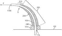
- FIG. 4is a cross-section view of a strain relieved catheter being displaced.
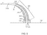
- FIG. 5illustrates a cross-section view of one embodiment of a tapered strain relief when the catheter is displaced.
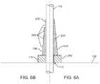
- FIG. 6Aillustrates a cross-section view of an embodiment of a tapered strain relief.
- FIG. 6Billustrates a cross-section view of a stepped embodiment of the tapered strain relief of FIG. 6A .
- FIG. 7Ais a side view of a spatially modulated strain relief.
- FIG. 7Billustrates the spatial modulation pattern of the strain relief of FIG. 7A unwrapped for clarity.
- FIG. 8is a table of strain relief performance.
- FIG. 9illustrates an embodiment of the increased safety stylet.
- FIG. 1is an illustration of a balloon device 100 , specifically a gastric balloon for weight reduction, positioned in a patient's stomach.
- Balloon devicesgenerally comprise two states: a pre-deployment or uninflated configuration and a deployed, inflated, or active configuration.
- a fluid delivered through a tube 110inflates the device 100 , where the tube 110 can also be referred to as a catheter or conduit.
- the tubemay pass through an opening 115 in wall 102 of the balloon device 100 .
- the tube 110can be coupled to a fluid path 112 , which fluidly connects the exterior and the interior of the balloon device.
- the end of catheter 110 that delivers the fluid to the interior reservoir of the balloonis the delivery end 110 A while the opposite end is the fill end 110 B, into which fluid is introduced.
- tube 110comprises a balloon, or delivery, end 110 A that extends through fluid path 112 into a central enclosed space or reservoir 104 of device 100 .
- Conduit 110is removed from the device once inflation is completed.
- fluid path 112must be sealed to prevent the inflation fluid from leaking out through fluid path 112 from reservoir 104 .
- a fill valvenot illustrated, seals the device 100 .
- the fill valve or the fluid path 112acts to constrain tube 110 to pass through wall 102 at a fixed angle relative to the local normal to the wall. In some variations the angle is 90 degrees (that is, tube 110 is normal to wall 102 ) while in other variations tube 110 may pass through wall 102 at a shallower angle, even approaching 0 degrees.
- FIG. 2Aillustrates the nominal configuration of a tube 110 passing through an opening 115 in a section of wall 102 of thin film material that defines balloon device 100 .
- Tube 110passes through a constraining element 116 , which may be, for example, a fluid path or fill valve.
- constraining element 116may be, for example, a fluid path or fill valve.
- tube 110has an axis 110 Z, which is constrained by element 116 to be parallel to the surface normal 102 N of wall 102 .
- FIG. 2Bwhen there is no significant pressure within device 100 wall 102 shape is distorted when tube 110 is pulled to one side so that the parallel relationship between tube axis 110 Z and wall normal 102 N is maintained.
- wall 102As balloon device 100 is filled with a fluid the internal pressure in device 100 increases and wall 102 experiences increasing tension. In turn, the increasing tension stiffens wall 102 making it resistant to distortion.
- wall 102is placed in tension and becomes relatively stiff.
- FIG. 3illustrates that tensioned wall 102 has limited ability to tilt locally to maintain the surface normal 102 N parallel to the catheter axis 110 Z. Instead, catheter 110 ′ must bend to when the fill end 110 B′ is deflected to the side.
- the fill valve and/or the fluid path 112may be designed to include angular strain relief.
- Angular strain reliefis a means of reinforcing a generally flexible, linear component—a wire or tube—that is attached to a stiff and somewhat fixed attachment point to prevent the linear component from being damaged or kinked by a lateral force, that is, being pulled by a force directed perpendicular to the linear component's axis.
- Eis the modulus of elasticity of the catheter material
- I ois the moment of inertia of the catheter with respect to its normal axis
- Mis the bending moment (that is, force applied to bend) applied to the catheter.
- the radiuscan be increased by changing the material to one with a higher modulus of elasticity (that is, a fixed applied force will bend a stiffer material less) or changing the geometry of the catheter to increase the moment of inertia.
- a higher modulus of elasticitythat is, a fixed applied force will bend a stiffer material less
- I o⁇ ⁇ ( D 4 - d 4 ) 64 , ( 2 )
- Dis the outer diameter of the catheter and d is its inner diameter.
- Rdepends strongly on the wall thickness (D ⁇ d)/2. For a catheter with a fixed inner diameter the wall thickness increases linearly with outer diameter D.
- a tubewill kink as the bending radius decreases to become equal to the critical radius. While it is possible to stiffen the catheter by increasing the outer diameter of the entire catheter to make it harder to reach the critical radius, it is usually more desirable to maintain high flexibility over most of the length of the catheter to facilitate placement through a tortuous path that must be navigated between outside the body and the device's ultimate operational location.
- an angular strain reliefto prevent the catheter's bending radius from reaching the critical radius in the immediate vicinity of the device, where the catheter is angularly constrained by the connection to the device wall, while maintaining the flexibility of the majority of the length of the catheter.
- An angular strain reliefacts to reduce the inherent discontinuity between the stiff constraining element and the flexible catheter.
- the strain reliefin one variation, is designed to provide a transition zone along the catheter where the zone has a continuously varying stiffness (or, equivalently a continuously varying critical radius) such that it matches the constraining element at one end and the inherent properties of the catheter at the other. By eliminating any discontinuity along the catheter, the strain relief reduces the potential for kinking.
- the continuously varying strain reliefcan be approximated by a uniform strain relief or a stepped strain relief, each of which reduce the magnitude of the discontinuity between the stiff constraining element and the flexible catheter.
- FIG. 4illustrates a cross-section of a catheter with one embodiment of a strain-relief component 10 .
- Strain relief component 10is designed to be stiff enough to keep the bending radius in the interface region 200 near the connection to the device wall above the critical radius, yet flexible enough to bend towards the laterally displaced catheter to reduce the bending moment M felt by the portion of the catheter that extends beyond the end of the strain relief.
- strain relief component 10is a uniform coating or sleeve that covers catheter's 110 outer surface, changing either or both the effective stiffness of the catheter material or the outer diameter of catheter 110 in region 200 .
- FIG. 4illustrates catheter 110 after it has been pulled to the side by fill end 110 B.
- Catheter 110is a flexible, hollow, thin-walled tube.
- strain relief 10which is also a flexible tube-like element.
- the strain relieved catheterhas an increased bend radius in the interface region 200 generally and catheter 110 bends in the direction of the applied force F, as indicated by the arrow, significantly reducing the amount by which the catheter itself must bend in a terminus region 210 where strain relief 10 ends, thus increasing the bending radius, R, above the critical radius R C .
- the walls 230 of a tubular strain relief 10 Aare tapered. This taper creates a continuously varying stiffness and thus bending radius of the catheter in region 200 that corresponds to the variation in wall thickness.
- the relief 10 Ais designed to be about as stiff as wall 102 to which it is attached, significantly increasing the bending radius for a given lateral force F near collar 116 .
- the added stiffness of the strain reliefis almost zero and the strain relief itself has bent to point toward the fill end 110 B of the offset catheter, meaning there is no discontinuity in the effective stiffness of tube 110 in the terminus region 210 where the strain relief ends.
- the strain reliefeliminates the catheter bend radius from ever reaching R C .
- a tapered-wall embodiment of strain relief 10can be approximated by a stepped-wall embodiment 10 B.
- FIG. 6is divided into a right-side figure, FIG. 6A , which illustrates the continuously tapered strain relief 10 A of FIG. 5 while the left side figure, FIG. 6B , illustrates a stepped wall embodiment 10 B.
- a stepped-wall strain relief 10 Bcomprises a wall thickness that varies from thick to thin in stepped manner, wherein the steps 242 can be fabricated in a variety of ways.
- a single, thick strain reliefcan be cut away to create the desired stepped strain relief.
- the stepscan be formed by adding multiple thin layers of wall material, each successively shorter than the preceding layer.
- the step functioncan be molded or cast in one piece.
- FIG. 7Aillustrates a side view of catheter 110 with one variation of a spatially modulated strain relief 10 C.
- spatially modulated strain relief 10 Ccomprises a pattern 250 around the exterior of catheter 110 .
- pattern 250is a zig-zag pattern more clearly seen in FIG. 7B , which shows strain relief 10 C unwrapped from catheter 110 . That is, the figure illustrates the varying length of the spatially modulated strain relief wall (as measured from constrained end 240 ) as a function of angle, ⁇ , around catheter 110 .
- the spatial modulationis an elongated zig-zag pattern, which can also be described as a series of triangular shapes.
- Each triangular shape in this exampleis an isosceles triangle with a narrow base 252 and two elongated sides 254 .
- the width of the basehas been selected to be less than one half of the circumference of the catheter and also a fraction of the circumference. That is, there are a whole number, greater or equal to 2, of triangular shapes around the circumference.
- This patternis illustrative of desirable properties of a pattern for a spatially modulated strain relief.
- the wall of the strain relief itselfdoes not have a tapered thickness so it can be fabricated from a simple tube of material.
- the modulation functioncomprises only straight lines which are easier to create than curved lines.
- the modulation patternrepeats multiple times around the circumference of the catheter so there is little or no angular variation in the stiffness of the strain relief around the circumference of the catheter.
- a spatially modulated strain reliefis a separate component that surrounds the catheter or tube.
- the strain reliefis printed directly onto the catheter.
- the thickness and composition of the ink used in this printing processincreases the stiffness of the catheter just as a layer of tubing or molded overcoat would do.
- spatially modulated strain reliefis less preferred to simply printing the same features directly on the tubing. Conveniently, adding a printed strain relief can be accomplished with little or no extra expense if the catheter is already being printed with other markings. In some variations these markings are used to estimate the location of the delivery end 110 A of the catheter along the gastro-intestinal tract.
- FIG. 8is a table of experimental data illustrating the effectiveness of a spatially modulated strain relief to inhibit kinking. Testing was performed in a test fixture in which the test object (catheter) was held in a rigid channel with the free end pointing upwards. The free end of the catheter was allowed to drape over the edge of the table. Weights of increasing mass were loaded onto the free end in controlled, timed intervals. The mass at which kinking occurred was determined by visual observation of the shape of the catheter at the catheter/channel interface. As shown in the table, the weight required to induce a kink in the strain-relieved catheters was approximately 2.5 times greater than the weight required to kink an unmodified catheter.
- a fluid delivery systemfurther comprises a stylet for assisting in placement of a medical device.
- a styletis, essentially, a thin and relatively stiff, wire-like object that is used to push the medical device towards its intended placement location.
- the deviceis delicate and can be damaged if the thin wire tip of the stylet pushes too hard against the device.
- the styletmay not only puncture the device but may pass entirely through the device and injure the patient.
- FIG. 9illustrates an embodiment of an increased safety stylet.
- a styletis inserted into fill end 110 B of catheter 110 and fed into the catheter until its distal or push end 310 reaches the device at the end of the catheter.
- the patientmay initially attempt to swallow the device unassisted prior to stylet insertion, with the stylet being inserted to assist only if the patient is unable to swallow the device unassisted.
- the administering agentcan push the device to move it beyond the upper esophageal sphincter (UES), which may also been referred to as the inferior pharyngeal sphincter because it is located at the lower end of pharynx and guards the entrance into the esophagus where the patient's gag reflex has previous caused the patient to reject the device.
- UESesophageal sphincter
- compliant tip 320comprises a length of polymer tubing 315 attached to the push end 310 of stylet wire 305 .
- Polymer tubing 315may be polytetrafluoroethylene (PTFE), commonly called “heat-shrink” tubing, or any similar polymer such as polyetheretherketone (PEEK) or fluorinatedethylenepropylene (FEP).
- PTFEpolytetrafluoroethylene
- PEEKpolyetheretherketone
- FEPfluorinatedethylenepropylene
- stylet 300comprises an approximately 36-inch-long, 24 mil diameter stainless steel wire 305 .
- Push end 310 of wire 305is preferably rounded to reduce tearing of compliant tip 320 .
- a length of heat-shrink tubing 315 having an unshrunk inner diameter slightly greater than the 24 mil diameter of wire 305is positioned over the wire, leaving a pre-determined length of tubing, in this exemplary embodiment approximately 0.25 inches, protruding past push end 310 to serve as compliant tip 320 .
- the length of heat shrink tubinghas been selected to cover substantially the entire length of wire 305 to ensure the stylet is smooth and lubricious.
- tubing 315After positioning on wire 305 , the entire length of tubing 315 is heated above the shrinkage temperature. A smaller diameter mandrel wire may be inserted into protruding tip 320 . After heat-shrinking, tube 315 is tightly attached to wire 305 but, due to its smaller diameter, not tightly attached to the mandrel wire, if used. The mandrel wire is merely tooling and is removed after heat-shrinking.
Landscapes
- Health & Medical Sciences (AREA)
- Heart & Thoracic Surgery (AREA)
- Life Sciences & Earth Sciences (AREA)
- Animal Behavior & Ethology (AREA)
- Child & Adolescent Psychology (AREA)
- Veterinary Medicine (AREA)
- Public Health (AREA)
- Engineering & Computer Science (AREA)
- Biomedical Technology (AREA)
- General Health & Medical Sciences (AREA)
- Orthopedic Medicine & Surgery (AREA)
- Vascular Medicine (AREA)
- Nursing (AREA)
- Obesity (AREA)
- Biophysics (AREA)
- Pulmonology (AREA)
- Anesthesiology (AREA)
- Hematology (AREA)
- Media Introduction/Drainage Providing Device (AREA)
Abstract
Description
| TABLE 1 |
| Balloon Device Uses |
| Medical Specialty | Procedure | ||
| Carotid & Neurovascular | Angioplasty, Occlusion | ||
| ENT | Sinuplasty | ||
| Cardiovascular | Angioplasty, Stent | ||
| Delivery, IVUS, | |||
| Vulnerable Plaque | |||
| detection | |||
| Structural Heart | Valvuloplasty, Heart Valve | ||
| sizing and dilation, Aortic | |||
| pump & Cardioplegia, | |||
| Occlusion, Sizing | |||
| Electrophysiology | Cryoablation | ||
| EVAR | Sizing, placement, tacking | ||
| balloons, endovascular | |||
| stent graft delivery | |||
| GI | Esophageal & biliary | ||
| dilation, GI access & stent | |||
| placement | |||
| Venous & AV access | High pressure balloons | ||
| Iliac | PTA balloons | ||
| SFA | Long PTA balloons | ||
| Popliteal, infrapopliteal, | low profile balloons | ||
| pedal, plantar | |||
| MI Orthopaedic | Kyphoplasty | ||
| Peripheral Vascular | Renal, thrombus aspiration, | ||
| stent graft delivery | |||
| Cosmetic Surgery | Breast Augmentation | ||
where
where D is the outer diameter of the catheter and d is its inner diameter. Clearly, the radius R depends strongly on the wall thickness (D−d)/2. For a catheter with a fixed inner diameter the wall thickness increases linearly with outer diameter D.
RC=K(D2/(D−d)), (3)
where the scaling factor K is nearly constant for all catheter materials of interest. As a general rule it is desirable to have a small critical radius, which allows one to bend a catheter sharply without kinking. In any particular use, the catheter inner and outer diameter are selected to achieve the required RC, with the critical radius generally decreasing with decreasing outer diameter (the inner diameter is typically fixed to achieve the desired fluid flow at a fixed pressure).
Claims (20)
Priority Applications (1)
| Application Number | Priority Date | Filing Date | Title |
|---|---|---|---|
| US16/713,583US11497900B2 (en) | 2018-12-13 | 2019-12-13 | Enhanced fluid delivery system |
Applications Claiming Priority (2)
| Application Number | Priority Date | Filing Date | Title |
|---|---|---|---|
| US201862779158P | 2018-12-13 | 2018-12-13 | |
| US16/713,583US11497900B2 (en) | 2018-12-13 | 2019-12-13 | Enhanced fluid delivery system |
Publications (2)
| Publication Number | Publication Date |
|---|---|
| US20200188644A1 US20200188644A1 (en) | 2020-06-18 |
| US11497900B2true US11497900B2 (en) | 2022-11-15 |
Family
ID=71073156
Family Applications (1)
| Application Number | Title | Priority Date | Filing Date |
|---|---|---|---|
| US16/713,583Active2040-11-27US11497900B2 (en) | 2018-12-13 | 2019-12-13 | Enhanced fluid delivery system |
Country Status (5)
| Country | Link |
|---|---|
| US (1) | US11497900B2 (en) |
| EP (1) | EP3886774A4 (en) |
| CN (1) | CN113242723A (en) |
| BR (1) | BR112021011198A2 (en) |
| WO (1) | WO2020123916A1 (en) |
Cited By (5)
| Publication number | Priority date | Publication date | Assignee | Title |
|---|---|---|---|---|
| US11766346B2 (en) | 2012-02-21 | 2023-09-26 | Allurion Technologies, Inc. | Methods and devices for deploying and releasing a temporary implant within the body |
| US11828377B2 (en) | 2018-07-06 | 2023-11-28 | Allurion Technologies, Inc. | Binary fluid control valve system |
| US12109138B2 (en) | 2018-02-26 | 2024-10-08 | Allurion Technologies, Inc. | Automatic-sealing balloon-filling catheter system |
| US12245962B2 (en) | 2023-04-12 | 2025-03-11 | Allurion Technologies, Inc. | Balloon sealing and fill valve |
| US12246163B2 (en) | 2023-04-12 | 2025-03-11 | Allurion Technologies, Inc. | Automatic-sealing balloon-filling catheter system |
Families Citing this family (2)
| Publication number | Priority date | Publication date | Assignee | Title |
|---|---|---|---|---|
| EP3886774A4 (en) | 2018-12-13 | 2022-09-28 | Allurion Technologies, Inc. | Enhanced fluid delivery system |
| TWI758074B (en)* | 2021-01-20 | 2022-03-11 | 州巧科技股份有限公司 | Flexible elastic tube |
Citations (126)
| Publication number | Priority date | Publication date | Assignee | Title |
|---|---|---|---|---|
| US2911988A (en) | 1956-01-24 | 1959-11-10 | Clarence J Ravn | Moisture releasable drain valve |
| US3586018A (en) | 1969-02-24 | 1971-06-22 | Thermia Verken Ab | Self-closing valve |
| US3638733A (en) | 1970-03-03 | 1972-02-01 | Kidde & Co Walter | Heat operated fire extinguisher |
| US3853116A (en) | 1971-06-21 | 1974-12-10 | Investors In Ventures Inc | Implant methods and devices for influencing body fluids |
| US4133315A (en) | 1976-12-27 | 1979-01-09 | Berman Edward J | Method and apparatus for reducing obesity |
| US4141771A (en) | 1976-04-28 | 1979-02-27 | Imperial Chemical Industries Limited | Method of thermoforming |
| US4370374A (en) | 1979-09-04 | 1983-01-25 | Plate Bonn Gesellschaft Mit Beschrankter Haftung | Multilayer plastic film, process for its production and its use |
| US4614188A (en)* | 1980-08-15 | 1986-09-30 | Seymour Bazell | Balloon catheter |
| US4723547A (en)* | 1985-05-07 | 1988-02-09 | C. R. Bard, Inc. | Anti-obesity balloon placement system |
| US4732188A (en) | 1987-06-15 | 1988-03-22 | Gt Development Corporation | Fuel tank cap with pressure/thermal relief |
| US4739758A (en) | 1986-05-19 | 1988-04-26 | Criticare Systems, Inc. | Apparatus for stomach cavity reduction |
| US4842007A (en) | 1988-09-08 | 1989-06-27 | Guard Associates, Inc. | Self-sealing valve for inflated bodies |
| US4899747A (en) | 1981-12-10 | 1990-02-13 | Garren Lloyd R | Method and appartus for treating obesity |
| US4949756A (en) | 1988-08-31 | 1990-08-21 | Uresil Corporation | One-way valve |
| US5018665A (en) | 1990-02-13 | 1991-05-28 | Hale Fire Pump Company | Thermal relief valve |
| US5092847A (en)* | 1990-04-06 | 1992-03-03 | Sherwood Medical Company | Enteral feeding tube stylet |
| US5181921A (en) | 1990-05-25 | 1993-01-26 | Kaken Co., Ltd. | Detachable balloon with two self-sealing valves |
| US5222970A (en)* | 1991-09-06 | 1993-06-29 | William A. Cook Australia Pty. Ltd. | Method of and system for mounting a vascular occlusion balloon on a delivery catheter |
| US5336123A (en) | 1992-04-08 | 1994-08-09 | Vonco Products, Inc. | Inflatable flexible pouch |
| US5348537A (en) | 1992-07-15 | 1994-09-20 | Advanced Cardiovascular Systems, Inc. | Catheter with intraluminal sealing element |
| US5496203A (en) | 1994-03-25 | 1996-03-05 | Murray; Robert H. | Balloon valve assembly |
| US5507808A (en) | 1994-10-26 | 1996-04-16 | Becker; Hilton | Filling tube and seal construction |
| US5595521A (en) | 1994-01-10 | 1997-01-21 | M & D Balloons, Inc. | Balloons and balloon valves |
| US5950624A (en) | 1996-07-09 | 1999-09-14 | Hart; William T. | Oral appliance having hollow body |
| WO2000012167A1 (en) | 1998-08-26 | 2000-03-09 | Microcatheters Pty. Ltd. | Catheter guide |
| US6162251A (en) | 1999-05-25 | 2000-12-19 | Novamed Medical Products Manufacturing, Inc. | Saline implant having single valve with primary and secondary closures |
| US6259953B1 (en) | 1998-07-28 | 2001-07-10 | Intermedics, Inc. | cardiac lead with active fixation and biocompatible lubricant |
| US20010018929A1 (en) | 2000-03-02 | 2001-09-06 | Hamai Industries Limited | Safety valve |
| US6375972B1 (en) | 2000-04-26 | 2002-04-23 | Control Delivery Systems, Inc. | Sustained release drug delivery devices, methods of use, and methods of manufacturing thereof |
| US6460541B1 (en) | 2000-11-07 | 2002-10-08 | Polyzen, Inc. | Heat-sealed inflatable article, and method of making the same |
| US20020183777A1 (en) | 2001-06-04 | 2002-12-05 | Shannon Donald T. | Shrouded strain relief medical balloon device and method of use |
| CN1387418A (en) | 1999-08-12 | 2002-12-25 | 波滕西亚医疗公司 | Food intake restriction apparatus with wireless energy transmission |
| US20020198470A1 (en) | 2001-06-26 | 2002-12-26 | Imran Mir A. | Capsule and method for treating or diagnosing the intestinal tract |
| US20030106583A1 (en) | 2001-12-12 | 2003-06-12 | Hsi-Kuang Weng | General-purpose thermally-sensitive safety apparatus |
| US20030171768A1 (en) | 2002-03-07 | 2003-09-11 | Mcghan Jim J. | Self-deflating intragastric balloon |
| US6644336B2 (en) | 2001-06-12 | 2003-11-11 | Oil States Industries, Inc. | Method and apparatus for automatic shutoff of a valve when a substance is present in a flow of fluid |
| US20030229384A1 (en) | 2000-06-20 | 2003-12-11 | Celsion Corporation | Method and apparatus for treatment of tissue adjacent a bodily conduit with a compression balloon |
| US20030229263A1 (en) | 2000-04-14 | 2003-12-11 | Connors Kevin G. | Treatment of patients with a compressible attenuation device |
| US20040044353A1 (en) | 2002-08-30 | 2004-03-04 | James Gannoe | Methods and devices for maintaining a space occupying device in a relatively fixed location within a stomach |
| US6712832B2 (en) | 2001-10-15 | 2004-03-30 | Tilak M. Shah | Low-pressure medical balloons and method of making same |
| US20040073249A1 (en)* | 2000-06-15 | 2004-04-15 | Trotta Thomas N. | Balloon catheter with stiffening wire transition |
| US20040101540A1 (en) | 1999-09-01 | 2004-05-27 | John Cooker | Oral delivery system and method for making same |
| US20040146559A1 (en) | 2002-09-28 | 2004-07-29 | Sowden Harry S. | Dosage forms having an inner core and outer shell with different shapes |
| US20040186502A1 (en) | 2003-03-19 | 2004-09-23 | Sampson Douglas C. | Self-Inflating intragastric volume-occupying device |
| US6814097B2 (en) | 2001-03-20 | 2004-11-09 | Teleflex Gfi Control Systems L.P. | Pressure relief device |
| US20050055039A1 (en) | 2003-07-28 | 2005-03-10 | Polymorfix, Inc. | Devices and methods for pyloric anchoring |
| US20050096750A1 (en) | 2002-11-01 | 2005-05-05 | Jonathan Kagan | Apparatus and methods for treatment of morbid obesity |
| US20050150548A1 (en) | 2003-03-02 | 2005-07-14 | Toshio Kita | Safety valve |
| US6939292B2 (en) | 2001-06-20 | 2005-09-06 | Olympus Corporation | Capsule type endoscope |
| US20060004323A1 (en)* | 2004-04-21 | 2006-01-05 | Exploramed Nc1, Inc. | Apparatus and methods for dilating and modifying ostia of paranasal sinuses and other intranasal or paranasal structures |
| WO2006020929A2 (en) | 2004-08-13 | 2006-02-23 | Phagia Technology | Intragastric volume-occupying device |
| US20060222705A1 (en) | 2005-03-31 | 2006-10-05 | Flanner Henry H | Pharmaceutical tablet and apparatus and method for making |
| US20070010791A1 (en) | 2005-07-07 | 2007-01-11 | Bristol-Myers Squibb Company | Valve for inflatable chamber of medical device |
| US7172613B2 (en) | 2000-03-13 | 2007-02-06 | Districlass Medical Sa | Intragastric device for treating morbid obesity |
| US20070078476A1 (en) | 2004-10-12 | 2007-04-05 | Hull Wendell C Sr | Overweight control apparatuses for insertion into the stomach |
| CA2925648A1 (en) | 2005-10-31 | 2007-05-10 | Reshape Medical, Inc. | Intragastric space filler with safety device |
| US20070250094A1 (en) | 2006-04-19 | 2007-10-25 | Joshua Makower | Devices and methods for treatment of obesity |
| JP2008513132A (en) | 2004-09-16 | 2008-05-01 | ジュヴァ・メディカル・インコーポレーテッド | Tissue augmentation device |
| US20080195226A1 (en) | 2006-09-02 | 2008-08-14 | Williams Michael S | Intestinal sleeves and associated deployment systems and methods |
| US20080243071A1 (en) | 2007-03-30 | 2008-10-02 | Quijano Rodolfo C | Intragastric balloon system and therapeutic processes and products |
| US20080241094A1 (en) | 2002-12-19 | 2008-10-02 | Baronova, Inc. | Ingestible formulations for transient, noninvasive reduction of gastric volume |
| US20080249635A1 (en) | 2007-04-05 | 2008-10-09 | Barry Weitzner | Gastric filler devices for obesity therapy |
| US20080269555A1 (en) | 2005-02-24 | 2008-10-30 | Compagnie Europeenne D'etude Et De Recherche De Di Spositifs Pour L'lmplantation Par Laparoscopie | Intragastric Balloon With Extraction Reinforcement |
| US20080276992A1 (en) | 2004-11-11 | 2008-11-13 | Kaoru Nomichi | Relief Valve Device |
| US20080306441A1 (en)* | 2007-04-10 | 2008-12-11 | Wilson-Cook Medical Inc. | Non-buckling balloon catheter with spring loaded floating flexible tip |
| US20090024227A1 (en) | 2004-09-16 | 2009-01-22 | Evera Medical, Inc. | Methods of forming a multilayer tissue implant to create an accordion effect on the outer layer |
| US7485093B2 (en) | 2002-04-25 | 2009-02-03 | Given Imaging Ltd. | Device and method for in-vivo sensing |
| CN101384231A (en) | 2006-02-17 | 2009-03-11 | 欧洲腹腔镜检植入装置研制公司 | Shape memory intragastric balloon |
| US20090118756A1 (en) | 2005-06-01 | 2009-05-07 | Nicolas Francois Michel Valencon | Intra-gastric balloon provided with a gel-containing valve, kit and use thereof |
| WO2009059803A1 (en) | 2007-11-09 | 2009-05-14 | Venera Khafizova | Externally inflatable gastric balloon device |
| WO2009059802A1 (en) | 2007-11-09 | 2009-05-14 | Venera Khafizova | Self-deflating gastric balloon device |
| US20090192535A1 (en) | 2007-12-20 | 2009-07-30 | Kasic Ii James | Swallowable Self-Expanding Gastric Space Occupying Device |
| US20090259246A1 (en) | 2008-04-14 | 2009-10-15 | Sherif Eskaros | Intragastric Volume-Occupying Device |
| US20090275919A1 (en)* | 2008-05-01 | 2009-11-05 | Edwards Lifesciences Corporation | Balloon Deployment Device and Method |
| US20090277515A1 (en) | 2008-05-07 | 2009-11-12 | Rainer Pechtold | Resettable thermal pressure relief device |
| US20090299327A1 (en) | 2008-06-02 | 2009-12-03 | Lorna Vista Medical, Inc. | Inflatable medical devices |
| EP2139439A2 (en) | 2007-04-13 | 2010-01-06 | Allergan, Inc. | Remote deflation of intragastric balloon |
| US20100062057A1 (en) | 2008-09-10 | 2010-03-11 | Pronova BioPharma Norge AS. | Formulation |
| US20100100116A1 (en) | 2008-10-16 | 2010-04-22 | Obalon Therapeutics, Inc. | Intragastric volume-occupying device and method for fabricating same |
| US20100114311A1 (en) | 2008-11-05 | 2010-05-06 | Hilton Becker | Multi-Lumen Breast Prothesis and Improved Valve Assembly Therefor |
| US20100121224A1 (en) | 2007-03-26 | 2010-05-13 | Jms Co., Ltd. | Balloon for measuring pressure related to oral cavity and method for producing the same |
| US20100168511A1 (en)* | 2008-12-29 | 2010-07-01 | Acclarent, Inc. | System and method for dilating an airway stenosis |
| US20100193050A1 (en) | 2006-11-06 | 2010-08-05 | Job Lizenz Gmbg & Co. Kg | Safety valve for a gas cylinder |
| US20100246165A1 (en) | 2009-03-31 | 2010-09-30 | Diaz Edmundo B | Invisible and/ or non-invisible designed inflatables combined with electric black ultra-violet lights and inflator nozzle fixture accessories |
| US20100274194A1 (en) | 2003-06-20 | 2010-10-28 | Allergan, Inc. | Two-way slit valve |
| US20110004236A1 (en) | 2009-07-01 | 2011-01-06 | E2 Llc | Systems and Methods for Treating Obesity and Type 2 Diabetes |
| US20110112383A1 (en) | 2005-11-08 | 2011-05-12 | Plensat, Inc | Devices, systems and methods for treatment of eating disorders |
| WO2011106157A1 (en) | 2010-02-25 | 2011-09-01 | Ethicon Endo-Surgery, Inc. | Devices for treating morbid obesity using hydrogel |
| CN201977967U (en) | 2011-01-18 | 2011-09-21 | 郭加 | Intragastric ball packing device for losing weight |
| US8183227B1 (en) | 2011-07-07 | 2012-05-22 | Chemo S. A. France | Compositions, kits and methods for nutrition supplementation |
| US20120141544A1 (en) | 2010-12-03 | 2012-06-07 | Fuisz Richard C | Solid Dosage Form That Promotes Reliable Oral, Esophageal and GI Transit |
| US20120141545A1 (en) | 2010-12-03 | 2012-06-07 | Fuisz Richard C | Solid Dosage Form That Promotes Reliable Oral, Esophageal and GI Transit |
| US8202291B1 (en) | 2011-01-21 | 2012-06-19 | Obalon Therapeutics, Inc. | Intragastric device |
| US8292911B2 (en) | 2011-01-21 | 2012-10-23 | Obalon Therapeutics, Inc. | Intragastric device |
| US20120273050A1 (en) | 2011-04-28 | 2012-11-01 | K&N Innovations, LLC | Automatic Shutoff Drain |
| US20130035711A1 (en) | 2010-10-18 | 2013-02-07 | Allergan, Inc. | Intragastric balloon for treating obesity |
| US20130165873A1 (en) | 2007-01-24 | 2013-06-27 | Acclarent, Inc. | Methods, devices and systems for treating and/or diagnosis of disorders of the ear, nose and throat |
| US20130190796A1 (en) | 2010-07-13 | 2013-07-25 | Loma Vista Medical, Inc. | "inflatable medical devices" |
| US20130218190A1 (en) | 2012-02-21 | 2013-08-22 | Allurion Technologies, Inc. | Methods and devices for deploying and releasing a temporary implant within the body |
| US20130289604A1 (en) | 2011-01-21 | 2013-10-31 | Obalon Therapeutics, Inc | Intragastric device |
| US20130296751A1 (en) | 2012-03-29 | 2013-11-07 | Ruth E. Martin | Oral device and method for the use thereof |
| US8585676B2 (en) | 2007-02-05 | 2013-11-19 | Polyzen Inc. | Multi-lumen lay-flat tubing, catheter articles comprising same, and method of manufacture thereof |
| US20140012363A1 (en)* | 2011-01-17 | 2014-01-09 | Novita Therapeutics, Llc | Ballstent device and methods of use |
| US20140066967A1 (en) | 2012-02-21 | 2014-03-06 | Allurion Technologies, Inc. | Anatomically adapted ingestible delivery systems and methods |
| US8740845B2 (en) | 2007-09-25 | 2014-06-03 | Polyzen Inc. | Multi-layer film welded articulated balloon |
| US20140180252A1 (en)* | 2012-12-20 | 2014-06-26 | Sabry Gabriel | Feeding Tube with Inflatable Balloon Component |
| US20140188151A1 (en) | 2012-02-21 | 2014-07-03 | Allurion Technologies, Inc. | Methods and devices for deploying and releasing a temporary implant within the body |
| US8784486B2 (en) | 2008-04-28 | 2014-07-22 | Allergan, Inc. | Breast implants having a flush patch and methods of using same to augment or reconstruct a breast |
| WO2015066545A1 (en) | 2013-11-01 | 2015-05-07 | Allurion Technologies, Inc. | Methods and devices for deploying and releasing a temporary implant within the body |
| US20150196408A1 (en) | 2012-02-21 | 2015-07-16 | Allurion Technologies, Inc. | Methods and devices for deploying and releasing a temporary implant within the body |
| US20160010758A1 (en) | 2013-03-04 | 2016-01-14 | Kawasaki Jukogyo Kabushiki Kaisha | Fusible plug type pressure relief valve |
| US20160045719A1 (en)* | 2014-08-15 | 2016-02-18 | Acclarent, Inc. | Shaft system for balloon dilation |
| US20160109029A1 (en) | 2014-10-15 | 2016-04-21 | Baker Products Ltd. | Temperature controlled purge valve with washer/o-ring seal stack |
| WO2016145076A1 (en) | 2015-03-09 | 2016-09-15 | Allurion Technologies, Inc. | Methods and devices for deploying and releasing a temporary implant within the body |
| US9463106B2 (en) | 2012-09-10 | 2016-10-11 | Boston Scientific Scimed, Inc. | Catheter with releasable balloon and related methods |
| US20170211715A1 (en) | 2016-01-21 | 2017-07-27 | GM Global Technology Operations LLC | Oil bypass valve with temporary spacer to provide initially opened fluid circuit |
| WO2017136840A1 (en) | 2016-02-05 | 2017-08-10 | Allurion Technologies, Inc. | Method of fabrication for devices for deploying and releasing a temporary implant within the body |
| US20170312111A1 (en) | 2016-04-27 | 2017-11-02 | Synerz Medical, Inc. | Anchorless Intragastric Device For Treating Obesity |
| WO2018142761A1 (en) | 2017-01-31 | 2018-08-09 | 日本ライフライン株式会社 | Balloon catheter |
| US20180236203A1 (en)* | 2015-03-19 | 2018-08-23 | Prytime Medical Devices, Inc. | System and method for low-profile occlusion balloon catheter |
| US20180311484A1 (en) | 2017-05-01 | 2018-11-01 | Allurion Technologies, Inc. | Method of fabrication for devices for deploying and releasing a temporary implant within the body |
| US20190076152A1 (en)* | 2016-06-02 | 2019-03-14 | Prytime Medical Devices, Inc. | System and method for low profile occlusion balloon catheter |
| US10238516B1 (en) | 2017-11-01 | 2019-03-26 | Barix Medical Corp. | Simplified implantable gastric balloon system with self deflating timer |
| US20190262157A1 (en) | 2018-02-26 | 2019-08-29 | Allurion Technologies, Inc. | Automatic-sealing balloon-filling catheter system |
| WO2020010359A1 (en) | 2018-07-06 | 2020-01-09 | Allurion Technologies, Inc. | Binary fluid control valve system |
| WO2020123916A1 (en) | 2018-12-13 | 2020-06-18 | Allurion Technologies, Inc. | Enhanced fluid delivery system |
- 2019
- 2019-12-13EPEP19894743.4Apatent/EP3886774A4/ennot_activeWithdrawn
- 2019-12-13BRBR112021011198-0Apatent/BR112021011198A2/ennot_activeApplication Discontinuation
- 2019-12-13CNCN201980082477.XApatent/CN113242723A/enactivePending
- 2019-12-13WOPCT/US2019/066185patent/WO2020123916A1/ennot_activeCeased
- 2019-12-13USUS16/713,583patent/US11497900B2/enactiveActive
Patent Citations (169)
| Publication number | Priority date | Publication date | Assignee | Title |
|---|---|---|---|---|
| US2911988A (en) | 1956-01-24 | 1959-11-10 | Clarence J Ravn | Moisture releasable drain valve |
| US3586018A (en) | 1969-02-24 | 1971-06-22 | Thermia Verken Ab | Self-closing valve |
| US3638733A (en) | 1970-03-03 | 1972-02-01 | Kidde & Co Walter | Heat operated fire extinguisher |
| US3853116A (en) | 1971-06-21 | 1974-12-10 | Investors In Ventures Inc | Implant methods and devices for influencing body fluids |
| US4141771A (en) | 1976-04-28 | 1979-02-27 | Imperial Chemical Industries Limited | Method of thermoforming |
| US4133315A (en) | 1976-12-27 | 1979-01-09 | Berman Edward J | Method and apparatus for reducing obesity |
| US4370374A (en) | 1979-09-04 | 1983-01-25 | Plate Bonn Gesellschaft Mit Beschrankter Haftung | Multilayer plastic film, process for its production and its use |
| US4614188A (en)* | 1980-08-15 | 1986-09-30 | Seymour Bazell | Balloon catheter |
| US4899747A (en) | 1981-12-10 | 1990-02-13 | Garren Lloyd R | Method and appartus for treating obesity |
| US4723547A (en)* | 1985-05-07 | 1988-02-09 | C. R. Bard, Inc. | Anti-obesity balloon placement system |
| US4739758A (en) | 1986-05-19 | 1988-04-26 | Criticare Systems, Inc. | Apparatus for stomach cavity reduction |
| US4732188A (en) | 1987-06-15 | 1988-03-22 | Gt Development Corporation | Fuel tank cap with pressure/thermal relief |
| US4949756A (en) | 1988-08-31 | 1990-08-21 | Uresil Corporation | One-way valve |
| US4842007A (en) | 1988-09-08 | 1989-06-27 | Guard Associates, Inc. | Self-sealing valve for inflated bodies |
| US5018665A (en) | 1990-02-13 | 1991-05-28 | Hale Fire Pump Company | Thermal relief valve |
| US5092847A (en)* | 1990-04-06 | 1992-03-03 | Sherwood Medical Company | Enteral feeding tube stylet |
| US5181921A (en) | 1990-05-25 | 1993-01-26 | Kaken Co., Ltd. | Detachable balloon with two self-sealing valves |
| US5222970A (en)* | 1991-09-06 | 1993-06-29 | William A. Cook Australia Pty. Ltd. | Method of and system for mounting a vascular occlusion balloon on a delivery catheter |
| US5336123A (en) | 1992-04-08 | 1994-08-09 | Vonco Products, Inc. | Inflatable flexible pouch |
| US5348537A (en) | 1992-07-15 | 1994-09-20 | Advanced Cardiovascular Systems, Inc. | Catheter with intraluminal sealing element |
| US5595521A (en) | 1994-01-10 | 1997-01-21 | M & D Balloons, Inc. | Balloons and balloon valves |
| US5496203A (en) | 1994-03-25 | 1996-03-05 | Murray; Robert H. | Balloon valve assembly |
| US5507808A (en) | 1994-10-26 | 1996-04-16 | Becker; Hilton | Filling tube and seal construction |
| US5950624A (en) | 1996-07-09 | 1999-09-14 | Hart; William T. | Oral appliance having hollow body |
| US6259953B1 (en) | 1998-07-28 | 2001-07-10 | Intermedics, Inc. | cardiac lead with active fixation and biocompatible lubricant |
| WO2000012167A1 (en) | 1998-08-26 | 2000-03-09 | Microcatheters Pty. Ltd. | Catheter guide |
| US6162251A (en) | 1999-05-25 | 2000-12-19 | Novamed Medical Products Manufacturing, Inc. | Saline implant having single valve with primary and secondary closures |
| CN1387418A (en) | 1999-08-12 | 2002-12-25 | 波滕西亚医疗公司 | Food intake restriction apparatus with wireless energy transmission |
| US20040101540A1 (en) | 1999-09-01 | 2004-05-27 | John Cooker | Oral delivery system and method for making same |
| US20010018929A1 (en) | 2000-03-02 | 2001-09-06 | Hamai Industries Limited | Safety valve |
| US6367499B2 (en) | 2000-03-02 | 2002-04-09 | Hamai Industries Limited | Safety valve |
| US7172613B2 (en) | 2000-03-13 | 2007-02-06 | Districlass Medical Sa | Intragastric device for treating morbid obesity |
| US20030229263A1 (en) | 2000-04-14 | 2003-12-11 | Connors Kevin G. | Treatment of patients with a compressible attenuation device |
| US6375972B1 (en) | 2000-04-26 | 2002-04-23 | Control Delivery Systems, Inc. | Sustained release drug delivery devices, methods of use, and methods of manufacturing thereof |
| US20040073249A1 (en)* | 2000-06-15 | 2004-04-15 | Trotta Thomas N. | Balloon catheter with stiffening wire transition |
| US20030229384A1 (en) | 2000-06-20 | 2003-12-11 | Celsion Corporation | Method and apparatus for treatment of tissue adjacent a bodily conduit with a compression balloon |
| US6460541B1 (en) | 2000-11-07 | 2002-10-08 | Polyzen, Inc. | Heat-sealed inflatable article, and method of making the same |
| US6814097B2 (en) | 2001-03-20 | 2004-11-09 | Teleflex Gfi Control Systems L.P. | Pressure relief device |
| US20020183777A1 (en) | 2001-06-04 | 2002-12-05 | Shannon Donald T. | Shrouded strain relief medical balloon device and method of use |
| US6644336B2 (en) | 2001-06-12 | 2003-11-11 | Oil States Industries, Inc. | Method and apparatus for automatic shutoff of a valve when a substance is present in a flow of fluid |
| US6939292B2 (en) | 2001-06-20 | 2005-09-06 | Olympus Corporation | Capsule type endoscope |
| US20020198470A1 (en) | 2001-06-26 | 2002-12-26 | Imran Mir A. | Capsule and method for treating or diagnosing the intestinal tract |
| US6712832B2 (en) | 2001-10-15 | 2004-03-30 | Tilak M. Shah | Low-pressure medical balloons and method of making same |
| US20030106583A1 (en) | 2001-12-12 | 2003-06-12 | Hsi-Kuang Weng | General-purpose thermally-sensitive safety apparatus |
| US20030171768A1 (en) | 2002-03-07 | 2003-09-11 | Mcghan Jim J. | Self-deflating intragastric balloon |
| US7485093B2 (en) | 2002-04-25 | 2009-02-03 | Given Imaging Ltd. | Device and method for in-vivo sensing |
| US20040044353A1 (en) | 2002-08-30 | 2004-03-04 | James Gannoe | Methods and devices for maintaining a space occupying device in a relatively fixed location within a stomach |
| US20040146559A1 (en) | 2002-09-28 | 2004-07-29 | Sowden Harry S. | Dosage forms having an inner core and outer shell with different shapes |
| US20050096750A1 (en) | 2002-11-01 | 2005-05-05 | Jonathan Kagan | Apparatus and methods for treatment of morbid obesity |
| US20080241094A1 (en) | 2002-12-19 | 2008-10-02 | Baronova, Inc. | Ingestible formulations for transient, noninvasive reduction of gastric volume |
| US20050150548A1 (en) | 2003-03-02 | 2005-07-14 | Toshio Kita | Safety valve |
| US20040186502A1 (en) | 2003-03-19 | 2004-09-23 | Sampson Douglas C. | Self-Inflating intragastric volume-occupying device |
| US20100274194A1 (en) | 2003-06-20 | 2010-10-28 | Allergan, Inc. | Two-way slit valve |
| US20050055039A1 (en) | 2003-07-28 | 2005-03-10 | Polymorfix, Inc. | Devices and methods for pyloric anchoring |
| US20060004323A1 (en)* | 2004-04-21 | 2006-01-05 | Exploramed Nc1, Inc. | Apparatus and methods for dilating and modifying ostia of paranasal sinuses and other intranasal or paranasal structures |
| JP2008515464A (en) | 2004-08-09 | 2008-05-15 | バロノヴァ,インク. | Pylor mooring device and method |
| WO2006020929A2 (en) | 2004-08-13 | 2006-02-23 | Phagia Technology | Intragastric volume-occupying device |
| JP2008513132A (en) | 2004-09-16 | 2008-05-01 | ジュヴァ・メディカル・インコーポレーテッド | Tissue augmentation device |
| US20090024227A1 (en) | 2004-09-16 | 2009-01-22 | Evera Medical, Inc. | Methods of forming a multilayer tissue implant to create an accordion effect on the outer layer |
| US20090048684A1 (en) | 2004-09-16 | 2009-02-19 | Evera Medical, Inc. | Methods of forming a multilayer tissue implant having a compliance that simulates tissue |
| US20070078476A1 (en) | 2004-10-12 | 2007-04-05 | Hull Wendell C Sr | Overweight control apparatuses for insertion into the stomach |
| US20080276992A1 (en) | 2004-11-11 | 2008-11-13 | Kaoru Nomichi | Relief Valve Device |
| US20080269555A1 (en) | 2005-02-24 | 2008-10-30 | Compagnie Europeenne D'etude Et De Recherche De Di Spositifs Pour L'lmplantation Par Laparoscopie | Intragastric Balloon With Extraction Reinforcement |
| US20060222705A1 (en) | 2005-03-31 | 2006-10-05 | Flanner Henry H | Pharmaceutical tablet and apparatus and method for making |
| US20090118756A1 (en) | 2005-06-01 | 2009-05-07 | Nicolas Francois Michel Valencon | Intra-gastric balloon provided with a gel-containing valve, kit and use thereof |
| US20070010791A1 (en) | 2005-07-07 | 2007-01-11 | Bristol-Myers Squibb Company | Valve for inflatable chamber of medical device |
| CA2925648A1 (en) | 2005-10-31 | 2007-05-10 | Reshape Medical, Inc. | Intragastric space filler with safety device |
| US20110112383A1 (en) | 2005-11-08 | 2011-05-12 | Plensat, Inc | Devices, systems and methods for treatment of eating disorders |
| CN101384231A (en) | 2006-02-17 | 2009-03-11 | 欧洲腹腔镜检植入装置研制公司 | Shape memory intragastric balloon |
| US20070250094A1 (en) | 2006-04-19 | 2007-10-25 | Joshua Makower | Devices and methods for treatment of obesity |
| US20080195226A1 (en) | 2006-09-02 | 2008-08-14 | Williams Michael S | Intestinal sleeves and associated deployment systems and methods |
| US20100193050A1 (en) | 2006-11-06 | 2010-08-05 | Job Lizenz Gmbg & Co. Kg | Safety valve for a gas cylinder |
| US20130165873A1 (en) | 2007-01-24 | 2013-06-27 | Acclarent, Inc. | Methods, devices and systems for treating and/or diagnosis of disorders of the ear, nose and throat |
| US8585676B2 (en) | 2007-02-05 | 2013-11-19 | Polyzen Inc. | Multi-lumen lay-flat tubing, catheter articles comprising same, and method of manufacture thereof |
| US20100121224A1 (en) | 2007-03-26 | 2010-05-13 | Jms Co., Ltd. | Balloon for measuring pressure related to oral cavity and method for producing the same |
| US20080243071A1 (en) | 2007-03-30 | 2008-10-02 | Quijano Rodolfo C | Intragastric balloon system and therapeutic processes and products |
| US20080249635A1 (en) | 2007-04-05 | 2008-10-09 | Barry Weitzner | Gastric filler devices for obesity therapy |
| US20080306441A1 (en)* | 2007-04-10 | 2008-12-11 | Wilson-Cook Medical Inc. | Non-buckling balloon catheter with spring loaded floating flexible tip |
| EP2139439A2 (en) | 2007-04-13 | 2010-01-06 | Allergan, Inc. | Remote deflation of intragastric balloon |
| US20100174307A1 (en) | 2007-04-13 | 2010-07-08 | Allergan, Inc. | Remote deflation of intragastric balloon |
| JP2010523280A (en) | 2007-04-13 | 2010-07-15 | アラーガン、インコーポレイテッド | Remote contraction of intragastric balloon |
| US8740845B2 (en) | 2007-09-25 | 2014-06-03 | Polyzen Inc. | Multi-layer film welded articulated balloon |
| WO2009059802A1 (en) | 2007-11-09 | 2009-05-14 | Venera Khafizova | Self-deflating gastric balloon device |
| WO2009059803A1 (en) | 2007-11-09 | 2009-05-14 | Venera Khafizova | Externally inflatable gastric balloon device |
| US8287562B2 (en) | 2007-12-20 | 2012-10-16 | 7L, Llc | Swallowable self-expanding gastric space occupying device |
| US20090192535A1 (en) | 2007-12-20 | 2009-07-30 | Kasic Ii James | Swallowable Self-Expanding Gastric Space Occupying Device |
| JP2011517611A (en) | 2008-04-14 | 2011-06-16 | ゴア エンタープライズ ホールディングス,インコーポレイティド | Device occupying the stomach volume |
| US20090259246A1 (en) | 2008-04-14 | 2009-10-15 | Sherif Eskaros | Intragastric Volume-Occupying Device |
| US8784486B2 (en) | 2008-04-28 | 2014-07-22 | Allergan, Inc. | Breast implants having a flush patch and methods of using same to augment or reconstruct a breast |
| US20090275919A1 (en)* | 2008-05-01 | 2009-11-05 | Edwards Lifesciences Corporation | Balloon Deployment Device and Method |
| US20090277515A1 (en) | 2008-05-07 | 2009-11-12 | Rainer Pechtold | Resettable thermal pressure relief device |
| US20090299327A1 (en) | 2008-06-02 | 2009-12-03 | Lorna Vista Medical, Inc. | Inflatable medical devices |
| US20100062057A1 (en) | 2008-09-10 | 2010-03-11 | Pronova BioPharma Norge AS. | Formulation |
| US20100137897A1 (en) | 2008-10-16 | 2010-06-03 | Obalon Therapeutics, Inc. | Intragastric device |
| US7854745B2 (en) | 2008-10-16 | 2010-12-21 | Obalon Therapeutics, Inc. | Intragastric device |
| US20100100116A1 (en) | 2008-10-16 | 2010-04-22 | Obalon Therapeutics, Inc. | Intragastric volume-occupying device and method for fabricating same |
| US20100114311A1 (en) | 2008-11-05 | 2010-05-06 | Hilton Becker | Multi-Lumen Breast Prothesis and Improved Valve Assembly Therefor |
| US20100168511A1 (en)* | 2008-12-29 | 2010-07-01 | Acclarent, Inc. | System and method for dilating an airway stenosis |
| US20100246165A1 (en) | 2009-03-31 | 2010-09-30 | Diaz Edmundo B | Invisible and/ or non-invisible designed inflatables combined with electric black ultra-violet lights and inflator nozzle fixture accessories |
| US20110004236A1 (en) | 2009-07-01 | 2011-01-06 | E2 Llc | Systems and Methods for Treating Obesity and Type 2 Diabetes |
| WO2011106157A1 (en) | 2010-02-25 | 2011-09-01 | Ethicon Endo-Surgery, Inc. | Devices for treating morbid obesity using hydrogel |
| US20130190796A1 (en) | 2010-07-13 | 2013-07-25 | Loma Vista Medical, Inc. | "inflatable medical devices" |
| US20130035711A1 (en) | 2010-10-18 | 2013-02-07 | Allergan, Inc. | Intragastric balloon for treating obesity |
| US20120141545A1 (en) | 2010-12-03 | 2012-06-07 | Fuisz Richard C | Solid Dosage Form That Promotes Reliable Oral, Esophageal and GI Transit |
| US20120141544A1 (en) | 2010-12-03 | 2012-06-07 | Fuisz Richard C | Solid Dosage Form That Promotes Reliable Oral, Esophageal and GI Transit |
| US20140012363A1 (en)* | 2011-01-17 | 2014-01-09 | Novita Therapeutics, Llc | Ballstent device and methods of use |
| CN201977967U (en) | 2011-01-18 | 2011-09-21 | 郭加 | Intragastric ball packing device for losing weight |
| US9662239B2 (en) | 2011-01-21 | 2017-05-30 | Obalon Therapeutics, Inc. | Intragastric device |
| US9827128B2 (en) | 2011-01-21 | 2017-11-28 | Obalon Therapeutics, Inc. | Intragastric device |
| EP3117865A1 (en) | 2011-01-21 | 2017-01-18 | Obalon Therapeutics, Inc. | Intragastric device |
| US8292911B2 (en) | 2011-01-21 | 2012-10-23 | Obalon Therapeutics, Inc. | Intragastric device |
| US20130289604A1 (en) | 2011-01-21 | 2013-10-31 | Obalon Therapeutics, Inc | Intragastric device |
| US20120232576A1 (en) | 2011-01-21 | 2012-09-13 | Obalon Therapeutics, Inc. | Intragastric device |
| US8202291B1 (en) | 2011-01-21 | 2012-06-19 | Obalon Therapeutics, Inc. | Intragastric device |
| US20120273050A1 (en) | 2011-04-28 | 2012-11-01 | K&N Innovations, LLC | Automatic Shutoff Drain |
| US8183227B1 (en) | 2011-07-07 | 2012-05-22 | Chemo S. A. France | Compositions, kits and methods for nutrition supplementation |
| WO2014074625A1 (en) | 2012-02-21 | 2014-05-15 | Allurion Technologies, Inc. | Anatomically adapted ingestible delivery systems and methods |
| US10786379B2 (en) | 2012-02-21 | 2020-09-29 | Allurion Technologies, Inc. | Methods and devices for deploying and releasing a temporary implant within the body |
| US20140066967A1 (en) | 2012-02-21 | 2014-03-06 | Allurion Technologies, Inc. | Anatomically adapted ingestible delivery systems and methods |
| US20180042747A1 (en) | 2012-02-21 | 2018-02-15 | Allurion Technologies, Inc. | Methods and devices for deploying and releasing a temporary implant within the body |
| US20140188151A1 (en) | 2012-02-21 | 2014-07-03 | Allurion Technologies, Inc. | Methods and devices for deploying and releasing a temporary implant within the body |
| US9849018B2 (en) | 2012-02-21 | 2017-12-26 | Allurion Technologies, Inc. | Ingestible delivery systems and methods |
| US8814898B2 (en) | 2012-02-21 | 2014-08-26 | Allurion Techologies, Inc. | Methods and devices for deploying and releasing a temporary implant within the body |
| US20140296903A1 (en) | 2012-02-21 | 2014-10-02 | Allurion Technologies, Inc. | Methods and devices for deploying and releasing a temporary implant within the body |
| US8870907B2 (en) | 2012-02-21 | 2014-10-28 | Allurion Technologies, Inc. | Methods and devices for deploying and releasing a temporary implant within the body |
| EP2817062A1 (en) | 2012-02-21 | 2014-12-31 | Allurion Technologies, Inc. | Methods and devices for deploying and releasing a temporary implant within the body |
| US8974483B2 (en) | 2012-02-21 | 2015-03-10 | Allurion Technologies, Inc. | Methods and devices for deploying and releasing a temporary implant within the body |
| US20130218190A1 (en) | 2012-02-21 | 2013-08-22 | Allurion Technologies, Inc. | Methods and devices for deploying and releasing a temporary implant within the body |
| US20150196408A1 (en) | 2012-02-21 | 2015-07-16 | Allurion Technologies, Inc. | Methods and devices for deploying and releasing a temporary implant within the body |
| US9827129B2 (en) | 2012-02-21 | 2017-11-28 | Allurion Technologies, Inc. | Methods and devices for deploying and releasing a temporary implant within the body |
| US20130267984A1 (en) | 2012-02-21 | 2013-10-10 | Allurion Technologies, Inc. | Methods and devices for deploying and releasing a temporary implant within the body |
| US20180071127A1 (en) | 2012-02-21 | 2018-03-15 | Allurion Technologies, Inc. | Ingestible delivery systems and methods |
| US9387107B2 (en) | 2012-02-21 | 2016-07-12 | Allurion Technologies, Inc. | Methods and devices for deploying and releasing a temporary implant within the body |
| US10729572B2 (en) | 2012-02-21 | 2020-08-04 | Allurion Technologies, Inc. | Methods and devices for deploying and releasing a temporary implant within the body |
| US20160278957A1 (en) | 2012-02-21 | 2016-09-29 | Allurion Technologies, Inc. | Methods and devices for deploying and releasing a temporary implant within the body |
| US20180344498A1 (en) | 2012-02-21 | 2018-12-06 | Allurion Technologies, Inc. | Methods and devices for deploying and releasing a temporary implant within the body |
| CA2865056A1 (en) | 2012-02-21 | 2013-08-29 | Allurion Technologies, Inc. | Methods and devices for deploying and releasing a temporary implant within the body |
| WO2013126593A1 (en) | 2012-02-21 | 2013-08-29 | Allurion Technologies, Inc. | Methods and devices for deploying and releasing a temporary implant within the body |
| US10307279B2 (en) | 2012-02-21 | 2019-06-04 | Allurion Technologies, Inc. | Ingestible delivery systems and methods |
| US10182932B2 (en) | 2012-02-21 | 2019-01-22 | Allurion Technologies, Inc. | Methods and devices for deploying and releasing a temporary implant within the body |
| US20130296751A1 (en) | 2012-03-29 | 2013-11-07 | Ruth E. Martin | Oral device and method for the use thereof |
| US9463106B2 (en) | 2012-09-10 | 2016-10-11 | Boston Scientific Scimed, Inc. | Catheter with releasable balloon and related methods |
| US20140180252A1 (en)* | 2012-12-20 | 2014-06-26 | Sabry Gabriel | Feeding Tube with Inflatable Balloon Component |
| US20160010758A1 (en) | 2013-03-04 | 2016-01-14 | Kawasaki Jukogyo Kabushiki Kaisha | Fusible plug type pressure relief valve |
| WO2015066545A1 (en) | 2013-11-01 | 2015-05-07 | Allurion Technologies, Inc. | Methods and devices for deploying and releasing a temporary implant within the body |
| US20160045719A1 (en)* | 2014-08-15 | 2016-02-18 | Acclarent, Inc. | Shaft system for balloon dilation |
| US20160109029A1 (en) | 2014-10-15 | 2016-04-21 | Baker Products Ltd. | Temperature controlled purge valve with washer/o-ring seal stack |
| WO2016145076A1 (en) | 2015-03-09 | 2016-09-15 | Allurion Technologies, Inc. | Methods and devices for deploying and releasing a temporary implant within the body |
| US20180236203A1 (en)* | 2015-03-19 | 2018-08-23 | Prytime Medical Devices, Inc. | System and method for low-profile occlusion balloon catheter |
| US20170211715A1 (en) | 2016-01-21 | 2017-07-27 | GM Global Technology Operations LLC | Oil bypass valve with temporary spacer to provide initially opened fluid circuit |
| WO2017136840A1 (en) | 2016-02-05 | 2017-08-10 | Allurion Technologies, Inc. | Method of fabrication for devices for deploying and releasing a temporary implant within the body |
| US20170312111A1 (en) | 2016-04-27 | 2017-11-02 | Synerz Medical, Inc. | Anchorless Intragastric Device For Treating Obesity |
| US20190076152A1 (en)* | 2016-06-02 | 2019-03-14 | Prytime Medical Devices, Inc. | System and method for low profile occlusion balloon catheter |
| WO2018142761A1 (en) | 2017-01-31 | 2018-08-09 | 日本ライフライン株式会社 | Balloon catheter |
| US20180311484A1 (en) | 2017-05-01 | 2018-11-01 | Allurion Technologies, Inc. | Method of fabrication for devices for deploying and releasing a temporary implant within the body |
| US10238516B1 (en) | 2017-11-01 | 2019-03-26 | Barix Medical Corp. | Simplified implantable gastric balloon system with self deflating timer |
| US10470908B2 (en) | 2018-02-26 | 2019-11-12 | Allurion Technologies, Inc. | Automatic-sealing balloon-filling catheter system |
| US20190388259A1 (en) | 2018-02-26 | 2019-12-26 | Allurion Technologies, Inc. | Automatic-sealing balloon-filling catheter system |
| US20190388258A1 (en) | 2018-02-26 | 2019-12-26 | Allurion Technologies, Inc. | Automatic-sealing balloon-filling catheter system |
| US10583024B2 (en) | 2018-02-26 | 2020-03-10 | Allurion Technologies, Inc. | Automatic-sealing balloon-filling catheter system |
| US10588768B2 (en) | 2018-02-26 | 2020-03-17 | Allurion Technologies, Inc. | Automatic-sealing balloon-filling catheter system |
| US20200155335A1 (en) | 2018-02-26 | 2020-05-21 | Allurion Technologies, Inc. | Automatic-sealing balloon-filling catheter system |
| WO2019165449A1 (en) | 2018-02-26 | 2019-08-29 | Allurion Technologies, Inc. | Automatic-sealing balloon-filling catheter system |
| US20190262157A1 (en) | 2018-02-26 | 2019-08-29 | Allurion Technologies, Inc. | Automatic-sealing balloon-filling catheter system |
| WO2020010359A1 (en) | 2018-07-06 | 2020-01-09 | Allurion Technologies, Inc. | Binary fluid control valve system |
| US20200011442A1 (en) | 2018-07-06 | 2020-01-09 | Allurion Technologies, Inc. | Binary fluid control valve system |
| US11098813B2 (en) | 2018-07-06 | 2021-08-24 | Allurion Technologies, Inc. | Binary fluid control valve system |
| US20210341069A1 (en) | 2018-07-06 | 2021-11-04 | Allurion Technologies, Inc. | Binary fluid control valve system |
| WO2020123916A1 (en) | 2018-12-13 | 2020-06-18 | Allurion Technologies, Inc. | Enhanced fluid delivery system |
Non-Patent Citations (1)
| Title |
|---|
| Stony Brook Medicine "Obalon Swallowable Balloon Capsules" Feb. 21, 2017, 2 pages. Retrieved from the Internet [Sep. 2, 2020] URL: https://www.youtube.com/watch?v=CEznWcGacLl. |
Cited By (7)
| Publication number | Priority date | Publication date | Assignee | Title |
|---|---|---|---|---|
| US11766346B2 (en) | 2012-02-21 | 2023-09-26 | Allurion Technologies, Inc. | Methods and devices for deploying and releasing a temporary implant within the body |
| US12409056B2 (en) | 2012-02-21 | 2025-09-09 | Allurion Technologies, Llc | Methods and devices for deploying and releasing a temporary implant within the body |
| US12109138B2 (en) | 2018-02-26 | 2024-10-08 | Allurion Technologies, Inc. | Automatic-sealing balloon-filling catheter system |
| US11828377B2 (en) | 2018-07-06 | 2023-11-28 | Allurion Technologies, Inc. | Binary fluid control valve system |
| US12209677B2 (en) | 2018-07-06 | 2025-01-28 | Allurion Technologies, Inc. | Binary fluid control valve system |
| US12245962B2 (en) | 2023-04-12 | 2025-03-11 | Allurion Technologies, Inc. | Balloon sealing and fill valve |
| US12246163B2 (en) | 2023-04-12 | 2025-03-11 | Allurion Technologies, Inc. | Automatic-sealing balloon-filling catheter system |
Also Published As
| Publication number | Publication date |
|---|---|
| WO2020123916A1 (en) | 2020-06-18 |
| US20200188644A1 (en) | 2020-06-18 |
| EP3886774A4 (en) | 2022-09-28 |
| BR112021011198A2 (en) | 2021-08-31 |
| CN113242723A (en) | 2021-08-10 |
| EP3886774A1 (en) | 2021-10-06 |
Similar Documents
| Publication | Publication Date | Title |
|---|---|---|
| US11497900B2 (en) | Enhanced fluid delivery system | |
| JP5179377B2 (en) | Medical delivery system for delivery of medically useful payload | |
| US20110208284A1 (en) | Protective sleeve for a medical device, system comprising a protective sleeve and a medical device, and a method for the production thereof | |
| US8043279B2 (en) | Catheter and medical tube | |
| JP4295919B2 (en) | Method for improving penetration of catheter tip and stent | |
| US20060264907A1 (en) | Catheters having stiffening mechanisms | |
| JP2001218851A (en) | Catheter | |
| EP2829299B1 (en) | Balloon catheter | |
| US20150073391A1 (en) | Medical device with a movable tip | |
| JP6227193B2 (en) | Endoscopic treatment tool | |
| JP2008512196A (en) | Expandable transluminal sheath | |
| CN105963848B (en) | Balloon catheter | |
| US8585680B2 (en) | Endovascular device tip assembly incorporating a marker device and method for making the same | |
| EP2994184B1 (en) | An unravelable catheter | |
| US20150320985A1 (en) | Balloon catheter | |
| JP2015192727A (en) | tube stent delivery device | |
| JP6708615B2 (en) | Balloon catheter | |
| JP6882484B2 (en) | Anticanulation web | |
| JP7548922B2 (en) | Medical instrument set and method of use thereof | |
| US20210244913A1 (en) | Fluid delivery catheter | |
| JP2018130232A (en) | Medical long body | |
| JP5907027B2 (en) | catheter | |
| KR102863451B1 (en) | Catheter device capable of adjusting distal angle to display bending direction of catheter tip on handle and method using the same | |
| KR102852103B1 (en) | Distal angel adjustable catheter device having a stainless steel ring and method using the same | |
| US20060142839A1 (en) | External support device |
Legal Events
| Date | Code | Title | Description |
|---|---|---|---|
| FEPP | Fee payment procedure | Free format text:ENTITY STATUS SET TO UNDISCOUNTED (ORIGINAL EVENT CODE: BIG.); ENTITY STATUS OF PATENT OWNER: SMALL ENTITY | |
| FEPP | Fee payment procedure | Free format text:ENTITY STATUS SET TO SMALL (ORIGINAL EVENT CODE: SMAL); ENTITY STATUS OF PATENT OWNER: SMALL ENTITY | |
| AS | Assignment | Owner name:ALLURION TECHNOLOGIES, INC., MASSACHUSETTS Free format text:ASSIGNMENT OF ASSIGNORS INTEREST;ASSIGNORS:CHADWICK, SAMUEL;NELSON, DAVID W.;ELDER, ANDY;AND OTHERS;SIGNING DATES FROM 20191219 TO 20191231;REEL/FRAME:051662/0083 | |
| STPP | Information on status: patent application and granting procedure in general | Free format text:APPLICATION DISPATCHED FROM PREEXAM, NOT YET DOCKETED | |
| STPP | Information on status: patent application and granting procedure in general | Free format text:DOCKETED NEW CASE - READY FOR EXAMINATION | |
| STPP | Information on status: patent application and granting procedure in general | Free format text:NON FINAL ACTION MAILED | |
| STPP | Information on status: patent application and granting procedure in general | Free format text:FINAL REJECTION MAILED | |
| STPP | Information on status: patent application and granting procedure in general | Free format text:RESPONSE AFTER FINAL ACTION FORWARDED TO EXAMINER | |
| STPP | Information on status: patent application and granting procedure in general | Free format text:ADVISORY ACTION MAILED | |
| STPP | Information on status: patent application and granting procedure in general | Free format text:NON FINAL ACTION MAILED | |
| STPP | Information on status: patent application and granting procedure in general | Free format text:FINAL REJECTION MAILED | |
| STPP | Information on status: patent application and granting procedure in general | Free format text:RESPONSE AFTER FINAL ACTION FORWARDED TO EXAMINER | |
| STPP | Information on status: patent application and granting procedure in general | Free format text:NOTICE OF ALLOWANCE MAILED -- APPLICATION RECEIVED IN OFFICE OF PUBLICATIONS | |
| STPP | Information on status: patent application and granting procedure in general | Free format text:PUBLICATIONS -- ISSUE FEE PAYMENT VERIFIED | |
| STCF | Information on status: patent grant | Free format text:PATENTED CASE | |
| AS | Assignment | Owner name:FORTRESS CREDIT CORP., NEW YORK Free format text:SECURITY INTEREST;ASSIGNOR:ALLURION TECHNOLOGIES, LLC;REEL/FRAME:064456/0568 Effective date:20230801 Owner name:FORTRESS CREDIT CORP., NEW YORK Free format text:SECURITY INTEREST;ASSIGNOR:ALLURION TECHNOLOGIES, LLC;REEL/FRAME:064453/0271 Effective date:20230801 | |
| AS | Assignment | Owner name:RTW INVESTMENTS, LP, NEW YORK Free format text:SECURITY INTEREST;ASSIGNOR:ALLURION TECHNOLOGIES, LLC;REEL/FRAME:064662/0956 Effective date:20230801 | |
| AS | Assignment | Owner name:ACQUIOM AGENCY SERVICES LLC, COLORADO Free format text:SECURITY INTEREST;ASSIGNOR:ALLURION TECHNOLOGIES, LLC;REEL/FRAME:067135/0677 Effective date:20240416 Owner name:RTW INVESTMENTS, LP, NEW YORK Free format text:SECURITY INTEREST;ASSIGNOR:ALLURION TECHNOLOGIES, LLC;REEL/FRAME:067135/0251 Effective date:20240416 | |
| AS | Assignment | Owner name:ALLURION TECHNOLOGIES, LLC, MASSACHUSETTS Free format text:TERMINATION TO PATENT SECURITY AGREEMENT;ASSIGNOR:FORTRESS CREDIT CORP.;REEL/FRAME:067169/0870 Effective date:20240416 | |
| AS | Assignment | Owner name:ALLURION TECHNOLOGIES OPCO, INC., MASSACHUSETTS Free format text:CHANGE OF NAME;ASSIGNOR:ALLURION TECHNOLOGIES, INC.;REEL/FRAME:067428/0403 Effective date:20230731 Owner name:ALLURION TECHNOLOGIES, LLC, MASSACHUSETTS Free format text:MERGER AND CHANGE OF NAME;ASSIGNORS:ALLURION TECHNOLOGIES OPCO, INC.;COMPUTE HEALTH LLC;REEL/FRAME:067424/0616 Effective date:20230801 Owner name:ALLURION TECHNOLOGIES OPCO, INC., MASSACHUSETTS Free format text:MERGER;ASSIGNOR:COMPUTE HEALTH CORP.;REEL/FRAME:067424/0592 Effective date:20230801 | |
| AS | Assignment | Owner name:ACQUIOM AGENCY SERVICES LLC, COLORADO Free format text:CORRECTIVE ASSIGNMENT TO CORRECT THE PATENT NUMBER FROM 10307269 TO 10307279 PREVIOUSLY RECORDED ON REEL 67135 FRAME 677. ASSIGNOR(S) HEREBY CONFIRMS THE SECURITY INTEREST;ASSIGNOR:ALLURION TECHNOLOGIES, LLC;REEL/FRAME:067962/0692 Effective date:20240416 Owner name:RTW INVESTMENTS, LP, NEW YORK Free format text:CORRECTIVE ASSIGNMENT TO CORRECT THE PATENT NUMBER FROM 10307269 TO 10307279 PREVIOUSLY RECORDED ON REEL 67135 FRAME 251. ASSIGNOR(S) HEREBY CONFIRMS THE SECURITY INTEREST;ASSIGNOR:ALLURION TECHNOLOGIES, LLC;REEL/FRAME:067838/0268 Effective date:20240416 | |
| AS | Assignment | Owner name:ALLURION TECHNOLOGIES OPCO, INC., MASSACHUSETTS Free format text:CORRECTIVE ASSIGNMENT TO CORRECT THE WRONG PATENT NUMBER 10307269 TO PATENT NUMBER 10307279 PREVIOUSLY RECORDED AT REEL: 67424 FRAME: 403. ASSIGNOR(S) HEREBY CONFIRMS THE MERGER;ASSIGNOR:COMPUTE HEALTH CORP.;REEL/FRAME:068935/0273 Effective date:20230801 Owner name:ALLURION TECHNOLOGIES, LLC, MASSACHUSETTS Free format text:CORRECTIVE ASSIGNMENT TO CORRECT THE RECORD AND EXPUNGE PATENT NUMBER 10307269 AND REPLACE IT WITH 10307279 PREVIOUSLY RECORDED ON REEL 67424 FRAME 616. ASSIGNOR(S) HEREBY CONFIRMS THE MERGER AND CHANGE OF NAME;ASSIGNORS:ALLURION TECHNOLOGIES OPCO, INC.;COMPUTE HEALTH LLC;REEL/FRAME:068997/0947 Effective date:20230801 Owner name:ALLURION TECHNOLOGIES OPCO, INC., MASSACHUSETTS Free format text:CORRECTIVE ASSIGNMENT TO CORRECT THE EXPLUNGE PATENT NUMBER 10307269 AND REPLACE IT WITH 1037279 PREVIOUSLY RECORDED AT REEL: 67424 FRAME: 403. ASSIGNOR(S) HEREBY CONFIRMS THE ASSIGNMENT;ASSIGNOR:COMPUTE HEALTH CORP.;REEL/FRAME:068935/0273 Effective date:20230801 | |
| AS | Assignment | Owner name:ALLURION TECHNOLOGIES OPCO, INC., MASSACHUSETTS Free format text:CORRECTIVE ASSIGNMENT TO CORRECT THE THE RECORD AND EXPUNGE PATENT NUMBER 10307269 AND REPLACE IT WITH 10307279 PREVIOUSLY RECORDED ON REEL 67428 FRAME 403. ASSIGNOR(S) HEREBY CONFIRMS THE CHANGE OF NAME;ASSIGNOR:ALLURION TECHNOLOGIES, INC.;REEL/FRAME:070129/0072 Effective date:20230731 | |
| AS | Assignment | Owner name:ALLURION TECHNOLOGIES OPCO, INC., MASSACHUSETTS Free format text:CORRECTIVE ASSIGNMENT TO CORRECT PATENT NUMBER 10307269 AND REPLACE IT WITH 10307279 PREVIOUSLY RECORDED ON REEL 67424 FRAME 592. ASSIGNOR(S) HEREBY CONFIRMS THE MERGER;ASSIGNOR:COMPUTE HEALTH CORP.;REEL/FRAME:070191/0885 Effective date:20230801 |