US11497621B2 - Inserter for implanting a spinal implant - Google Patents
Inserter for implanting a spinal implantDownload PDFInfo
- Publication number
- US11497621B2 US11497621B2US16/416,543US201916416543AUS11497621B2US 11497621 B2US11497621 B2US 11497621B2US 201916416543 AUS201916416543 AUS 201916416543AUS 11497621 B2US11497621 B2US 11497621B2
- Authority
- US
- United States
- Prior art keywords
- inserter
- spinal implant
- implant
- proximal
- thumbwheel
- Prior art date
- Legal status (The legal status is an assumption and is not a legal conclusion. Google has not performed a legal analysis and makes no representation as to the accuracy of the status listed.)
- Active, expires
Links
Images


Classifications
- A—HUMAN NECESSITIES
- A61—MEDICAL OR VETERINARY SCIENCE; HYGIENE
- A61F—FILTERS IMPLANTABLE INTO BLOOD VESSELS; PROSTHESES; DEVICES PROVIDING PATENCY TO, OR PREVENTING COLLAPSING OF, TUBULAR STRUCTURES OF THE BODY, e.g. STENTS; ORTHOPAEDIC, NURSING OR CONTRACEPTIVE DEVICES; FOMENTATION; TREATMENT OR PROTECTION OF EYES OR EARS; BANDAGES, DRESSINGS OR ABSORBENT PADS; FIRST-AID KITS
- A61F2/00—Filters implantable into blood vessels; Prostheses, i.e. artificial substitutes or replacements for parts of the body; Appliances for connecting them with the body; Devices providing patency to, or preventing collapsing of, tubular structures of the body, e.g. stents
- A61F2/02—Prostheses implantable into the body
- A61F2/30—Joints
- A61F2/44—Joints for the spine, e.g. vertebrae, spinal discs
- A61F2/442—Intervertebral or spinal discs, e.g. resilient
- A—HUMAN NECESSITIES
- A61—MEDICAL OR VETERINARY SCIENCE; HYGIENE
- A61F—FILTERS IMPLANTABLE INTO BLOOD VESSELS; PROSTHESES; DEVICES PROVIDING PATENCY TO, OR PREVENTING COLLAPSING OF, TUBULAR STRUCTURES OF THE BODY, e.g. STENTS; ORTHOPAEDIC, NURSING OR CONTRACEPTIVE DEVICES; FOMENTATION; TREATMENT OR PROTECTION OF EYES OR EARS; BANDAGES, DRESSINGS OR ABSORBENT PADS; FIRST-AID KITS
- A61F2/00—Filters implantable into blood vessels; Prostheses, i.e. artificial substitutes or replacements for parts of the body; Appliances for connecting them with the body; Devices providing patency to, or preventing collapsing of, tubular structures of the body, e.g. stents
- A61F2/02—Prostheses implantable into the body
- A61F2/30—Joints
- A61F2/44—Joints for the spine, e.g. vertebrae, spinal discs
- A61F2/4455—Joints for the spine, e.g. vertebrae, spinal discs for the fusion of spinal bodies, e.g. intervertebral fusion of adjacent spinal bodies, e.g. fusion cages
- A61F2/447—Joints for the spine, e.g. vertebrae, spinal discs for the fusion of spinal bodies, e.g. intervertebral fusion of adjacent spinal bodies, e.g. fusion cages substantially parallelepipedal, e.g. having a rectangular or trapezoidal cross-section
- A—HUMAN NECESSITIES
- A61—MEDICAL OR VETERINARY SCIENCE; HYGIENE
- A61F—FILTERS IMPLANTABLE INTO BLOOD VESSELS; PROSTHESES; DEVICES PROVIDING PATENCY TO, OR PREVENTING COLLAPSING OF, TUBULAR STRUCTURES OF THE BODY, e.g. STENTS; ORTHOPAEDIC, NURSING OR CONTRACEPTIVE DEVICES; FOMENTATION; TREATMENT OR PROTECTION OF EYES OR EARS; BANDAGES, DRESSINGS OR ABSORBENT PADS; FIRST-AID KITS
- A61F2/00—Filters implantable into blood vessels; Prostheses, i.e. artificial substitutes or replacements for parts of the body; Appliances for connecting them with the body; Devices providing patency to, or preventing collapsing of, tubular structures of the body, e.g. stents
- A61F2/02—Prostheses implantable into the body
- A61F2/30—Joints
- A61F2/46—Special tools for implanting artificial joints
- A61F2/4603—Special tools for implanting artificial joints for insertion or extraction of endoprosthetic joints or of accessories thereof
- A61F2/4611—Special tools for implanting artificial joints for insertion or extraction of endoprosthetic joints or of accessories thereof of spinal prostheses
- A—HUMAN NECESSITIES
- A61—MEDICAL OR VETERINARY SCIENCE; HYGIENE
- A61F—FILTERS IMPLANTABLE INTO BLOOD VESSELS; PROSTHESES; DEVICES PROVIDING PATENCY TO, OR PREVENTING COLLAPSING OF, TUBULAR STRUCTURES OF THE BODY, e.g. STENTS; ORTHOPAEDIC, NURSING OR CONTRACEPTIVE DEVICES; FOMENTATION; TREATMENT OR PROTECTION OF EYES OR EARS; BANDAGES, DRESSINGS OR ABSORBENT PADS; FIRST-AID KITS
- A61F2/00—Filters implantable into blood vessels; Prostheses, i.e. artificial substitutes or replacements for parts of the body; Appliances for connecting them with the body; Devices providing patency to, or preventing collapsing of, tubular structures of the body, e.g. stents
- A61F2/02—Prostheses implantable into the body
- A61F2/30—Joints
- A61F2/44—Joints for the spine, e.g. vertebrae, spinal discs
- A61F2/4405—Joints for the spine, e.g. vertebrae, spinal discs for apophyseal or facet joints, i.e. between adjacent spinous or transverse processes
- A—HUMAN NECESSITIES
- A61—MEDICAL OR VETERINARY SCIENCE; HYGIENE
- A61F—FILTERS IMPLANTABLE INTO BLOOD VESSELS; PROSTHESES; DEVICES PROVIDING PATENCY TO, OR PREVENTING COLLAPSING OF, TUBULAR STRUCTURES OF THE BODY, e.g. STENTS; ORTHOPAEDIC, NURSING OR CONTRACEPTIVE DEVICES; FOMENTATION; TREATMENT OR PROTECTION OF EYES OR EARS; BANDAGES, DRESSINGS OR ABSORBENT PADS; FIRST-AID KITS
- A61F2/00—Filters implantable into blood vessels; Prostheses, i.e. artificial substitutes or replacements for parts of the body; Appliances for connecting them with the body; Devices providing patency to, or preventing collapsing of, tubular structures of the body, e.g. stents
- A61F2/02—Prostheses implantable into the body
- A61F2/30—Joints
- A61F2/46—Special tools for implanting artificial joints
- A61F2/4603—Special tools for implanting artificial joints for insertion or extraction of endoprosthetic joints or of accessories thereof
- A—HUMAN NECESSITIES
- A61—MEDICAL OR VETERINARY SCIENCE; HYGIENE
- A61F—FILTERS IMPLANTABLE INTO BLOOD VESSELS; PROSTHESES; DEVICES PROVIDING PATENCY TO, OR PREVENTING COLLAPSING OF, TUBULAR STRUCTURES OF THE BODY, e.g. STENTS; ORTHOPAEDIC, NURSING OR CONTRACEPTIVE DEVICES; FOMENTATION; TREATMENT OR PROTECTION OF EYES OR EARS; BANDAGES, DRESSINGS OR ABSORBENT PADS; FIRST-AID KITS
- A61F2/00—Filters implantable into blood vessels; Prostheses, i.e. artificial substitutes or replacements for parts of the body; Appliances for connecting them with the body; Devices providing patency to, or preventing collapsing of, tubular structures of the body, e.g. stents
- A61F2/02—Prostheses implantable into the body
- A61F2/30—Joints
- A61F2002/30001—Additional features of subject-matter classified in A61F2/28, A61F2/30 and subgroups thereof
- A61F2002/30003—Material related properties of the prosthesis or of a coating on the prosthesis
- A61F2002/3006—Properties of materials and coating materials
- A61F2002/3008—Properties of materials and coating materials radio-opaque, e.g. radio-opaque markers
- A—HUMAN NECESSITIES
- A61—MEDICAL OR VETERINARY SCIENCE; HYGIENE
- A61F—FILTERS IMPLANTABLE INTO BLOOD VESSELS; PROSTHESES; DEVICES PROVIDING PATENCY TO, OR PREVENTING COLLAPSING OF, TUBULAR STRUCTURES OF THE BODY, e.g. STENTS; ORTHOPAEDIC, NURSING OR CONTRACEPTIVE DEVICES; FOMENTATION; TREATMENT OR PROTECTION OF EYES OR EARS; BANDAGES, DRESSINGS OR ABSORBENT PADS; FIRST-AID KITS
- A61F2/00—Filters implantable into blood vessels; Prostheses, i.e. artificial substitutes or replacements for parts of the body; Appliances for connecting them with the body; Devices providing patency to, or preventing collapsing of, tubular structures of the body, e.g. stents
- A61F2/02—Prostheses implantable into the body
- A61F2/30—Joints
- A61F2002/30001—Additional features of subject-matter classified in A61F2/28, A61F2/30 and subgroups thereof
- A61F2002/30108—Shapes
- A61F2002/3011—Cross-sections or two-dimensional shapes
- A61F2002/30138—Convex polygonal shapes
- A61F2002/30151—Convex polygonal shapes rhomboidal or parallelogram-shaped
- A—HUMAN NECESSITIES
- A61—MEDICAL OR VETERINARY SCIENCE; HYGIENE
- A61F—FILTERS IMPLANTABLE INTO BLOOD VESSELS; PROSTHESES; DEVICES PROVIDING PATENCY TO, OR PREVENTING COLLAPSING OF, TUBULAR STRUCTURES OF THE BODY, e.g. STENTS; ORTHOPAEDIC, NURSING OR CONTRACEPTIVE DEVICES; FOMENTATION; TREATMENT OR PROTECTION OF EYES OR EARS; BANDAGES, DRESSINGS OR ABSORBENT PADS; FIRST-AID KITS
- A61F2/00—Filters implantable into blood vessels; Prostheses, i.e. artificial substitutes or replacements for parts of the body; Appliances for connecting them with the body; Devices providing patency to, or preventing collapsing of, tubular structures of the body, e.g. stents
- A61F2/02—Prostheses implantable into the body
- A61F2/30—Joints
- A61F2002/30001—Additional features of subject-matter classified in A61F2/28, A61F2/30 and subgroups thereof
- A61F2002/30108—Shapes
- A61F2002/3011—Cross-sections or two-dimensional shapes
- A61F2002/30138—Convex polygonal shapes
- A61F2002/30153—Convex polygonal shapes rectangular
- A—HUMAN NECESSITIES
- A61—MEDICAL OR VETERINARY SCIENCE; HYGIENE
- A61F—FILTERS IMPLANTABLE INTO BLOOD VESSELS; PROSTHESES; DEVICES PROVIDING PATENCY TO, OR PREVENTING COLLAPSING OF, TUBULAR STRUCTURES OF THE BODY, e.g. STENTS; ORTHOPAEDIC, NURSING OR CONTRACEPTIVE DEVICES; FOMENTATION; TREATMENT OR PROTECTION OF EYES OR EARS; BANDAGES, DRESSINGS OR ABSORBENT PADS; FIRST-AID KITS
- A61F2/00—Filters implantable into blood vessels; Prostheses, i.e. artificial substitutes or replacements for parts of the body; Appliances for connecting them with the body; Devices providing patency to, or preventing collapsing of, tubular structures of the body, e.g. stents
- A61F2/02—Prostheses implantable into the body
- A61F2/30—Joints
- A61F2002/30001—Additional features of subject-matter classified in A61F2/28, A61F2/30 and subgroups thereof
- A61F2002/30108—Shapes
- A61F2002/3011—Cross-sections or two-dimensional shapes
- A61F2002/30138—Convex polygonal shapes
- A61F2002/30156—Convex polygonal shapes triangular
- A—HUMAN NECESSITIES
- A61—MEDICAL OR VETERINARY SCIENCE; HYGIENE
- A61F—FILTERS IMPLANTABLE INTO BLOOD VESSELS; PROSTHESES; DEVICES PROVIDING PATENCY TO, OR PREVENTING COLLAPSING OF, TUBULAR STRUCTURES OF THE BODY, e.g. STENTS; ORTHOPAEDIC, NURSING OR CONTRACEPTIVE DEVICES; FOMENTATION; TREATMENT OR PROTECTION OF EYES OR EARS; BANDAGES, DRESSINGS OR ABSORBENT PADS; FIRST-AID KITS
- A61F2/00—Filters implantable into blood vessels; Prostheses, i.e. artificial substitutes or replacements for parts of the body; Appliances for connecting them with the body; Devices providing patency to, or preventing collapsing of, tubular structures of the body, e.g. stents
- A61F2/02—Prostheses implantable into the body
- A61F2/30—Joints
- A61F2002/30001—Additional features of subject-matter classified in A61F2/28, A61F2/30 and subgroups thereof
- A61F2002/30108—Shapes
- A61F2002/3011—Cross-sections or two-dimensional shapes
- A61F2002/30138—Convex polygonal shapes
- A61F2002/30158—Convex polygonal shapes trapezoidal
- A—HUMAN NECESSITIES
- A61—MEDICAL OR VETERINARY SCIENCE; HYGIENE
- A61F—FILTERS IMPLANTABLE INTO BLOOD VESSELS; PROSTHESES; DEVICES PROVIDING PATENCY TO, OR PREVENTING COLLAPSING OF, TUBULAR STRUCTURES OF THE BODY, e.g. STENTS; ORTHOPAEDIC, NURSING OR CONTRACEPTIVE DEVICES; FOMENTATION; TREATMENT OR PROTECTION OF EYES OR EARS; BANDAGES, DRESSINGS OR ABSORBENT PADS; FIRST-AID KITS
- A61F2/00—Filters implantable into blood vessels; Prostheses, i.e. artificial substitutes or replacements for parts of the body; Appliances for connecting them with the body; Devices providing patency to, or preventing collapsing of, tubular structures of the body, e.g. stents
- A61F2/02—Prostheses implantable into the body
- A61F2/30—Joints
- A61F2002/30001—Additional features of subject-matter classified in A61F2/28, A61F2/30 and subgroups thereof
- A61F2002/30316—The prosthesis having different structural features at different locations within the same prosthesis; Connections between prosthetic parts; Special structural features of bone or joint prostheses not otherwise provided for
- A61F2002/30535—Special structural features of bone or joint prostheses not otherwise provided for
- A61F2002/30593—Special structural features of bone or joint prostheses not otherwise provided for hollow
- A—HUMAN NECESSITIES
- A61—MEDICAL OR VETERINARY SCIENCE; HYGIENE
- A61F—FILTERS IMPLANTABLE INTO BLOOD VESSELS; PROSTHESES; DEVICES PROVIDING PATENCY TO, OR PREVENTING COLLAPSING OF, TUBULAR STRUCTURES OF THE BODY, e.g. STENTS; ORTHOPAEDIC, NURSING OR CONTRACEPTIVE DEVICES; FOMENTATION; TREATMENT OR PROTECTION OF EYES OR EARS; BANDAGES, DRESSINGS OR ABSORBENT PADS; FIRST-AID KITS
- A61F2/00—Filters implantable into blood vessels; Prostheses, i.e. artificial substitutes or replacements for parts of the body; Appliances for connecting them with the body; Devices providing patency to, or preventing collapsing of, tubular structures of the body, e.g. stents
- A61F2/02—Prostheses implantable into the body
- A61F2/30—Joints
- A61F2/30767—Special external or bone-contacting surface, e.g. coating for improving bone ingrowth
- A61F2/30771—Special external or bone-contacting surface, e.g. coating for improving bone ingrowth applied in original prostheses, e.g. holes or grooves
- A61F2002/30772—Apertures or holes, e.g. of circular cross section
- A61F2002/30777—Oblong apertures
- A—HUMAN NECESSITIES
- A61—MEDICAL OR VETERINARY SCIENCE; HYGIENE
- A61F—FILTERS IMPLANTABLE INTO BLOOD VESSELS; PROSTHESES; DEVICES PROVIDING PATENCY TO, OR PREVENTING COLLAPSING OF, TUBULAR STRUCTURES OF THE BODY, e.g. STENTS; ORTHOPAEDIC, NURSING OR CONTRACEPTIVE DEVICES; FOMENTATION; TREATMENT OR PROTECTION OF EYES OR EARS; BANDAGES, DRESSINGS OR ABSORBENT PADS; FIRST-AID KITS
- A61F2/00—Filters implantable into blood vessels; Prostheses, i.e. artificial substitutes or replacements for parts of the body; Appliances for connecting them with the body; Devices providing patency to, or preventing collapsing of, tubular structures of the body, e.g. stents
- A61F2/02—Prostheses implantable into the body
- A61F2/30—Joints
- A61F2/30767—Special external or bone-contacting surface, e.g. coating for improving bone ingrowth
- A61F2/30771—Special external or bone-contacting surface, e.g. coating for improving bone ingrowth applied in original prostheses, e.g. holes or grooves
- A61F2002/30772—Apertures or holes, e.g. of circular cross section
- A61F2002/30784—Plurality of holes
- A61F2002/30785—Plurality of holes parallel
- A—HUMAN NECESSITIES
- A61—MEDICAL OR VETERINARY SCIENCE; HYGIENE
- A61F—FILTERS IMPLANTABLE INTO BLOOD VESSELS; PROSTHESES; DEVICES PROVIDING PATENCY TO, OR PREVENTING COLLAPSING OF, TUBULAR STRUCTURES OF THE BODY, e.g. STENTS; ORTHOPAEDIC, NURSING OR CONTRACEPTIVE DEVICES; FOMENTATION; TREATMENT OR PROTECTION OF EYES OR EARS; BANDAGES, DRESSINGS OR ABSORBENT PADS; FIRST-AID KITS
- A61F2/00—Filters implantable into blood vessels; Prostheses, i.e. artificial substitutes or replacements for parts of the body; Appliances for connecting them with the body; Devices providing patency to, or preventing collapsing of, tubular structures of the body, e.g. stents
- A61F2/02—Prostheses implantable into the body
- A61F2/30—Joints
- A61F2/30767—Special external or bone-contacting surface, e.g. coating for improving bone ingrowth
- A61F2/30771—Special external or bone-contacting surface, e.g. coating for improving bone ingrowth applied in original prostheses, e.g. holes or grooves
- A61F2002/3082—Grooves
- A—HUMAN NECESSITIES
- A61—MEDICAL OR VETERINARY SCIENCE; HYGIENE
- A61F—FILTERS IMPLANTABLE INTO BLOOD VESSELS; PROSTHESES; DEVICES PROVIDING PATENCY TO, OR PREVENTING COLLAPSING OF, TUBULAR STRUCTURES OF THE BODY, e.g. STENTS; ORTHOPAEDIC, NURSING OR CONTRACEPTIVE DEVICES; FOMENTATION; TREATMENT OR PROTECTION OF EYES OR EARS; BANDAGES, DRESSINGS OR ABSORBENT PADS; FIRST-AID KITS
- A61F2/00—Filters implantable into blood vessels; Prostheses, i.e. artificial substitutes or replacements for parts of the body; Appliances for connecting them with the body; Devices providing patency to, or preventing collapsing of, tubular structures of the body, e.g. stents
- A61F2/02—Prostheses implantable into the body
- A61F2/30—Joints
- A61F2/30767—Special external or bone-contacting surface, e.g. coating for improving bone ingrowth
- A61F2/30771—Special external or bone-contacting surface, e.g. coating for improving bone ingrowth applied in original prostheses, e.g. holes or grooves
- A61F2002/30904—Special external or bone-contacting surface, e.g. coating for improving bone ingrowth applied in original prostheses, e.g. holes or grooves serrated profile, i.e. saw-toothed
- A—HUMAN NECESSITIES
- A61—MEDICAL OR VETERINARY SCIENCE; HYGIENE
- A61F—FILTERS IMPLANTABLE INTO BLOOD VESSELS; PROSTHESES; DEVICES PROVIDING PATENCY TO, OR PREVENTING COLLAPSING OF, TUBULAR STRUCTURES OF THE BODY, e.g. STENTS; ORTHOPAEDIC, NURSING OR CONTRACEPTIVE DEVICES; FOMENTATION; TREATMENT OR PROTECTION OF EYES OR EARS; BANDAGES, DRESSINGS OR ABSORBENT PADS; FIRST-AID KITS
- A61F2/00—Filters implantable into blood vessels; Prostheses, i.e. artificial substitutes or replacements for parts of the body; Appliances for connecting them with the body; Devices providing patency to, or preventing collapsing of, tubular structures of the body, e.g. stents
- A61F2/02—Prostheses implantable into the body
- A61F2/30—Joints
- A61F2/46—Special tools for implanting artificial joints
- A61F2/4603—Special tools for implanting artificial joints for insertion or extraction of endoprosthetic joints or of accessories thereof
- A61F2002/4625—Special tools for implanting artificial joints for insertion or extraction of endoprosthetic joints or of accessories thereof with relative movement between parts of the instrument during use
- A61F2002/4627—Special tools for implanting artificial joints for insertion or extraction of endoprosthetic joints or of accessories thereof with relative movement between parts of the instrument during use with linear motion along or rotating motion about the instrument axis or the implantation direction, e.g. telescopic, along a guiding rod, screwing inside the instrument
Definitions
- the present inventionrelates generally to spinal surgery and, more particularly, to a device for spinal fusion comprising a spinal fusion implant of non-bone construction to be introduced into any variety of spinal target sites.
- TLIFTransforaminal lumbar interbody fusion
- the spinal fusion implant of the present inventionmay be comprised of any suitable non-bone composition, including but not limited to polymer compositions (e.g. poly-ether-ether-ketone (PEEK) and/or poly-ether-ketone-ketone (PEKK)), ceramic, metal, or any combination of these materials.
- the spinal fusion implant of the present inventionmay be provided in any number of suitable shapes and sizes depending upon the particular surgical procedure or need.
- the spinal fusion implantmay be dimensioned for use in any part of the spine (e.g. cervical, lumbar and/or thoracic) without departing from the scope of the present invention.
- the implantmay be dimensioned, by way of example only, having a width ranging between 8 and 14 mm, a height ranging between 8 and 18 mm, and a length ranging between 25 and 45 mm.
- the spinal fusion implantincludes a top surface, a bottom surface, lateral sides, a proximal end, and a distal end.
- the spinal fusion implant of the present inventionmay be used to provide temporary or permanent fixation along an orthopedic target site. To do so, the spinal fusion implant may be introduced into a disc space while locked to a surgical insertion instrument and thereafter manipulated in the proper orientation and released. Once deposited in the disc space, the spinal fusion implant of the present invention effects fusion over time as the natural healing process integrates and binds the implant.
- the spinal fusion implant of the present inventionmay be provided with any number of additional features for promoting fusion, such as one or more apertures extending between the top and bottom surfaces which allow a boney bridge to form through the spinal fusion implant.
- the spinal implantmay also be preferably equipped with one or more lateral openings which facilitate visualization at the time of implantation and at subsequent clinical evaluations.
- the spinal fusion implantmay also be provided with any number of suitable anti-migration features to prevent the implant from migrating or moving from the disc space after implantation.
- suitable anti-migration featuresmay include, but are not necessarily limited to, angled teeth or ridges formed along the top and bottom surfaces of the implant and/or rod elements disposed within the distal and/or proximal ends.
- the spinal fusion implantmay be provided with one or more radiographic markers at the proximal and/or distal ends. These markers allow for a more detailed visualization of the implant during and after insertion (through radiography) and allow for a more accurate and effective placement of the implant.
- the proximal end of the spinal fusion implantmay be provided with a surface that is tapered (angled) to avoid dural impingement after implantation. Additionally, the tapered nature of the proximal surface can aid in overall fit of the spinal fusion implant within the intervertebral disc space. Significantly, the tapered proximal surface on the proximal end enables the spinal fusion implant to maximize contact with the posterior portion of the cortical ring of each adjacent vertebral body.
- the distal end of the spinal fusion implantmay be provided with a conical (bullet-shaped) shape including a pair of first tapered (angled) surfaces and a pair of second tapered (angled) surfaces.
- the first tapered surfacesextend between the lateral surfaces and the distal end of the implant, and function to distract the vertebrae adjacent to the target intervertebral space during certain methods of insertion of the spinal fusion implant.
- the second tapered surfacesextend between the top and bottom surfaces and the distal end of the spinal fusion implant, and function to maximize contact with the anterior portion of the cortical ring of each adjacent vertebral body.
- the second tapered surfacesprovide for a better fit with the contour of the vertebral body endplates, allowing for a more anterior positioning of the spinal fusion implant and thus advantageous utilization of the cortical rings of the vertebral bodies.
- the distal end of the spinal fusion implantmay be at least partially asymmetrically curved about the longitudinal axis to approximate the anterior portion of the cortical ring of each adjacent vertebral body when the implant is placed in its desired final oblique position.
- the spinal fusion implantmay be provided with a variable height along at least a portion of the implant.
- the variable heighttapers in a direction oblique to both the length and width of the implant.
- the oblique taperimparts a greater height to the anterior aspect of the intervertebral disc space when the spinal fusion implant is positioned obliquely within the disc space. Imparting a greater height to the anterior aspect of the disc space restores the natural lordotic curvature of the lumbar spine.
- the spinal fusion implantmay be provided with at least one set of variable opposing corner rounds varying in their radii along the length of the implant to allow for more gradual lead-in at the distal end which facilitates easier and safer insertion of the spinal fusion implant.
- the spinal fusion implantmay be further provided with asymmetric convex top and bottom surfaces between first and second lateral sides to approximate the anatomical concavities of the inferior endplate of the superior vertebra and the superior endplate of the inferior vertebra.
- the spinal fusion implantmay be further provided with asymmetrically convex top and bottom surfaces along the length of the implant between proximal and distal ends of the implant.
- the asymmetric curvatureenables the spinal fusion implant to even better match the anatomical concavities of the inferior endplate of the superior vertebra and the superior endplate of the inferior vertebra.
- the spinal fusion implantmay be introduced into a spinal target site through use of any of a variety of suitable surgical instruments having the capability to engage the implant.
- the spinal fusion implantis capable of being used in minimally invasive surgical procedures, needing only a relatively small operative corridor for insertion.
- the spinal fusion implantmay be inserted into the intervertebral space and rotated into final position. Once the implant has been positioned in its desired location within the intervertebral space, the user will then rotate the implant 90° such that the top and bottom surfaces face in a caudad/cephalad direction and the anti-migration features engage the vertebral bodies.
- the direction of rotationis critical to ensure proper placement of the implant such that the edges of the proximal surface rest on the cortical ring of the vertebral bodies and the proximal surface does not protrude into the spinal canal. For example, if the spinal fusion implant approaches a patient's spine posteriorly from the right with the (longer) first lateral side facing caudally, then implant must be rotated in a counter-clockwise direction to achieve proper positioning.
- a single spinal fusion implantmay be provided and inserted into an intervertebral disc space and positioned obliquely across the disc space such that the proximal and distal ends are on opposite sides of the midline of the intervertebral space.
- FIG. 1is a perspective view of an example of a spinal fusion implant according to one embodiment of the present invention
- FIG. 2is a second perspective view of the spinal fusion implant of FIG. 1 ;
- FIG. 3is a top view of the spinal fusion implant of FIG. 1 ;
- FIG. 4is a bottom view of the spinal fusion implant of FIG. 1 ;
- FIG. 5is a first side view of the spinal fusion implant of FIG. 1 ;
- FIG. 6is a second side view of the spinal fusion implant of FIG. 1 ;
- FIG. 7is a plan view of a proximal end of the spinal fusion implant of FIG. 1 ;
- FIG. 8is a detailed perspective view the proximal end of the spinal fusion implant of FIG. 1 ;
- FIG. 9is a detailed cross-section view of the proximal end of the spinal fusion implant of FIG. 1 ;
- FIG. 10is a plan view of a distal end of the spinal fusion implant of FIG. 1 ;
- FIG. 11is a cross-section view of the proximal end of the spinal fusion implant of FIG. 1 taken along the line 1 - 1 ;
- FIG. 12is a cross-section view of the distal end of the spinal fusion implant of FIG. 1 taken along the line 2 - 2 ;
- FIG. 13is a perspective view of an insertion instrument according to one embodiment of the present invention.
- FIG. 14is an exploded perspective view of the insertion instrument of FIG. 13 ;
- FIG. 15is a detailed perspective view of the distal end of the insertion instrument of FIG. 13 ;
- FIG. 16is a perspective view of the insertion instrument of FIG. 13 coupled to the spinal fusion implant of FIG. 1 ;
- FIG. 17is a perspective view of an implant trial instrument according to one embodiment of the present invention.
- FIG. 18is a side view of the distal head of the trial instrument of FIG. 17 in a first orientation
- FIG. 19is a side view of the distal head of the trial instrument of FIG. 17 in a second orientation
- FIG. 20is a side view of the distal head of the trial instrument of FIG. 17 in a third orientation
- FIG. 21 Ais a top plan view of an example of a spinal fusion implant inserted into an intervertebral disc space but not placed in a desired oblique configuration
- FIG. 21 Bis an example lateral x-ray indicating the position of radiographic markers of the spinal fusion implant placed in the configuration shown in FIG. 21 A;
- FIG. 22 Ais a top plan view of an example of a spinal fusion implant inserted into an intervertebral disc space placed in a desired oblique configuration
- FIG. 22 Bis an example of a lateral x-ray indicating the position of radiographic markers of the spinal fusion implant in the desired oblique configuration as shown FIG. 22 A.
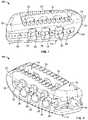
- FIGS. 1-2illustrate a spinal fusion implant 10 according to a first broad aspect of the present invention.
- the spinal fusion implant 10may be constructed of any suitable non-bone composition, including but not limited to polymer compositions (e. g. poly-ether-ether-ketone (PEEK) and/or poly-ether-ketone-ketone (PEKK)), ceramic, metal and/or any combination of polymer compositions, ceramic and metal.
- the spinal fusion implantmay be provided with a surface coating (for example, titanium plasma spray) to encourage bone growth onto endplate contacting surfaces.
- the spinal fusion implant 10 of the present inventionmay be provided in any number of shapes and sizes depending upon the particular surgical procedure or need.
- the spinal fusion implant 10may have a width ranging between 8 and 14 mm, a height ranging between 6 and 18 mm, and a length ranging between 20 and 45 mm.
- the spinal fusion implant 10 of the present inventionincludes a top surface 12 , a bottom surface 14 , first and second lateral sides 16 , 18 , a proximal (posterior) end 20 and a distal (anterior) end 22 .
- the spinal fusion implant 10 of the present inventionmay be used to provide temporary or permanent fixation within an orthopedic target site. To do so, the spinal fusion implant 10 may be introduced into a disc space while locked to a surgical insertion instrument and thereafter employed in the proper orientation and released, as explained in further detail below. Once deposited in the disc space, the spinal fusion implant 10 of the present invention effects spinal fusion over time as the natural healing process integrates and binds the implant.
- FIGS. 3-4illustrate the top and bottom surfaces 12 , 14 , respectively, of the spinal fusion implant 10 .
- the top and bottom surfaces 12 , 14are configured to engage the vertebral bodies adjoining the target disc space.
- the top and bottom surfaces 12 , 14each preferably include a plurality of anti-migration features designed to increase the friction between the spinal fusion implant 10 and the adjacent contacting surfaces of the vertebral bodies.
- Such anti-migration featuresmay include ridges (or teeth) 24 provided along the top surface 12 and/or bottom surface 14 .
- the frictionprohibits migration of the implant 10 after insertion into the intervertebral space and during the propagation of natural bony fusion. It should be appreciated by one skilled in the art that such ridges (or teeth) 24 can be oriented in a particular direction which will stabilize the implant in several degrees of rotation during placement.
- the spinal fusion implant 10 of the present inventionmay also be provided with one or more radiographic markers to allow for visual determination of proper implant placement.
- the radiographic markersmay be manufactured from any of a variety of suitable radiopaque materials, including but not limited to a metal, ceramic, and/or polymer material, preferably having radiopaque characteristics.
- the radiographic markersmay be provided in any size or shape suitable to facilitate effective and accurate visualization of implant placement.
- the spinal fusion implant 10include radiographic markers in the form of elongated cylinders extending generally perpendicularly through the implant 10 between the top and bottom surfaces 12 , 14 .
- radiographic markersmay include a shorter element which extends only partially from either the top surface 12 or the bottom surface 14 (that is, does not extend through the entire height of the implant 10 ).
- radiographic markersmay extend at least partially (but not fully) toward either or both of top and bottom surfaces 12 , 14 (that is, radiographic markers may be disposed completely within the body of the implant 10 ).
- the proximal end 20 of the spinal fusion implant 10may be provided with at least one radiographic marker 26 positioned extending at least partially through the implant between top and bottom surfaces 12 , 14 near the intersection of second lateral side 18 and proximal surface 40 .
- Radiographic marker 26may preferably indicate the position of the posterior-most portion of the implant 10 .
- Spinal fusion implant 10may include at least one radiographic marker positioned at the intersection of the second lateral side 18 and the distal end 22 .
- radiographic marker 28extending at least partially through the implant from the top surface 12
- radiographic marker 30extending at least partially through the implant from bottom surface 14 to identify the tallest points of the spinal fusion implant 10 .
- the distal end 22may be provided with radiographic marker 32 comprising a unitary element fully extending between the top and bottom surfaces 12 , 14 at or near the intersection of distal end 22 and first lateral side 16 .
- Radiographic marker 32may preferably indicate the position of the anterior-most portion of the spinal fusion implant as well as an indication of the anterior height of the implant.
- the orientation of radiographic markers 26 , 28 , 30 , 32provide an indication of the oblique placement of the spinal fusion implant 10 and the direction of rotation that is needed to bring the implant 10 into the desired positioning.
- the spinal fusion implant 10includes a large aperture 34 extending between top and bottom surfaces 12 , 14 .
- FIGS. 1-4illustrate aperture 34 extending in a vertical fashion between the top and bottom surfaces 12 , 14 .
- the aperture 34may be provided in any number of suitable shapes, including but not limited to generally circular, generally triangular and/or generally oblong (as shown by example in FIGS. 3 and 4 ).
- This single aperture 34is an additional feature for promoting fusion between the upper and lower vertebral bodies which allow a boney bridge to form through the spinal fusion implant 10 .
- this fusionmay be facilitated or augmented by including osteoinductive material(s) within the aperture 34 and/or adjacent to the spinal fusion implant 10 .
- osteoinductive materialsmay be introduced before, during, or after insertion of the spinal fusion implant 10 of the present invention, and may include (but are not necessarily limited to) autologous bone harvested from the patient receiving the spinal fusion implant 10 , bone allograft, bone xenograft, any number of non-bone implants (e.g. ceramic, metallic, polymer), bone morphogenic protein, and bio-resorbable compositions, including but not limited to any of a variety of poly (D, L-lactide-co-glycolide) based polymers, such as those disclosed in U.S. Pat. No. 6,013,853.
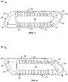
- FIGS. 5-6depict the spinal fusion implant 10 from side views.
- First and second lateral sides 16 , 18are generally parallel to one another (shown best in FIGS. 3-4 ).
- the spinal fusion implant 10may be further provided with one or more lateral apertures 36 extending generally perpendicularly therethrough from one lateral side 16 to the other 18 .
- Lateral apertures 36function to provide visualization at the time of implantation and at subsequent clinical evaluations.
- Lateral apertures 36may be provided in any of a variety of suitable shapes, including but not limited to generally circular, generally triangular, generally rectangular, and/or generally oblong (shown by example in FIG. 5-6 ), or any combination thereof.
- the spinal fusion implant 10 hereinincludes a pair of lateral apertures 36
- the spinal fusion implant 10may include any number of lateral apertures 36 as desired.
- the lateral apertures 36provide the ability to visualize the interior of the implant 10 during X-ray and/or other suitable imaging techniques which are undertaken from the lateral (or “side”) perspective of the implant 10 . If fusion has taken place, the lateral apertures 36 will provide a method for the surgeon to make follow up assessments as to the degree of fusion without any visual interference from the spinal fusion implant 10 . Further, the lateral apertures 36 will provide an avenue for cellular migration to the exterior of the spinal fusion implant 10 . Thus the spinal fusion implant 10 will serve as additional scaffolding for bone fusion on the exterior of the spinal fusion implant 10 .
- the spinal fusion implant 10further includes slots 38 extending from proximal surface 40 along first and second lateral sides 16 , 18 . Slots 38 are sized and dimensioned to interface with distal insertion tangs 122 on insertion instrument 100 to provide steerability and torsional support during insertion and insert-and-rotate maneuvers as will be described in greater detail below.
- FIG. 7illustrates the proximal end 20 of the spinal fusion implant 10 of the present invention.
- the proximal end 20has a proximal surface 40 that is tapered (angled) from the first lateral surface 16 to the second lateral surface 18 .
- This angular surfaceprovides an advantage by allowing an oblique positioning of the spinal fusion implant 10 within the intervertebral space, without protruding into the spinal canal to avoid dural impingement after insertion.
- the tapered nature of the proximal surface 40can aid in overall fit of the spinal fusion implant 10 within the vertebral disc space.
- the tapered proximal surface 40 on the proximal end 20enables the spinal fusion implant 10 to maximize contact with the posterior portion of the cortical ring of each adjacent vertebral body.
- the proximal end 20may include a proximal engagement recess 46 which extends inwardly in a generally perpendicular fashion relative to the proximal end 20 .
- a proximal engagement recess 46may be provided having any number of suitable shapes or cross-sections, including but not limited to circular or triangular.
- the proximal engagement recess 46may extend fully or at least partially along the length of the proximal surface 40 .
- Proximal engagement recess 46is dimensioned to receive and engage with an insertion tool (described below) for inserting the spinal fusion implant 10 into the intervertebral space.
- the proximal engagement recess 46is comprised of a keyed insertion slot 48 , a locking recess (undercut) 50 , and a locking wall 54 .
- Keyed insertion slot 48is complementary in shape to the rotational lock 128 on the inner shaft 108 .
- the rotational lock 128When the rotational lock 128 is inserted into the keyed insertion slot 48 , it falls into the locking recess 50 (or undercut) after it rotates) and abuts locking wall 52 , thereby locking the spinal fusion implant 10 with insertion instrument 100 and preventing the implant 10 and insertion instrument 100 from moving relative to one another.
- FIG. 10illustrates the distal end 22 of the spinal fusion implant 10 of the present invention.
- the distal end 22has a conical (bullet-shaped) distal nose including a pair of first tapered (angled) surfaces 54 and a pair of second tapered (angled) surfaces 56 .
- First tapered surfaces 54extend between lateral surfaces 16 , 18 and the distal end 22 .
- First tapered surface 54 extending from second lateral surface/side 18is generously curved between distal nose and lateral side 18 and functions to distract the vertebrae adjacent to the target intervertebral space during insertion of the spinal fusion implant 10 .
- the distal end 22is asymmetrically positioned relative to the longitudinal axis of the implant.
- the distal endis preferentially curved (curved surface 44 ) towards the second lateral side 18 .
- the asymmetric distal end 22facilitates insertion while providing maximal surface area of the spinal fusion implant 10 .
- the asymmetric distal end 22provides a gradual lead-in taper which protects nervous tissue in the spinal canal when placing the spinal fusion implant 10 into the disc space on its side and utilizing the insert-and-rotate technique. Once implanted and rotated, the asymmetrical distal end 22 provides increased structural support by approximating the anatomical shape of the anterior portion of the cortical ring of each adjacent vertebral body.
- the top and bottom surfaces 12 , 14may be angled or tapered from distal (anterior end) 22 to proximal (posterior) end 20 .
- the implant 10has a variable height tapering in a direction oblique to the length and width of the implant, as measured by the distance between the top and bottom surfaces 12 , 14 . Because the variable height of the implant tapers in a direction oblique to the length of the implant, the height of the implant at the distal end 22 is greater than the height of the proximal end 20 .
- the height of the first lateral side 16differs from the height of the second lateral side 18 along at least a portion of the length of the implant.
- the practical result of this tapering along a direction oblique to the length and width of the implantis that when the spinal fusion implant 10 is inserted obliquely within the disc space, the effective height correction occurs generally parallel to the sagittal plane (i.e. anterior to posterior). This provides for optimal restoration of the natural lordotic curvature of the lumbar spine.
- the oblique tapering of the implant 10 heightmay occur at an angle measuring from 5 to 15 degrees.
- the spinal fusion implant 10preferably has variable rounds on opposing corners of the implant 10 when looking at the implant along its longitudinal axis. These opposing-corner variable rounds (shown here as Rounds A and B) vary in their radius along the length of the implant. In the embodiment shown in FIGS. 11-12 , Rounds A-B have a larger radius at the distal end 22 and a smaller radius at the proximal end 20 . Smaller rounds (shown here as Rounds C and D) have constant and equal radii along the length of the spinal fusion implant. The radii at Rounds A and B are preferably approximately equal at any given cross-section along the entire length of the spinal fusion implant 10 . These opposing-corner variable rounds allow for more gradual lead-in at the distal end 22 which facilitates insertion of the spinal fusion implant 10 during insert and rotate maneuvers.
- Rounds A and Bvary in their radius along the length of the implant. In the embodiment shown in FIGS. 11-12 , Rounds A-B have a larger radius at the distal end
- the spinal fusion implantmay be further provided with asymmetric convex top and bottom surfaces between first and second lateral sides to approximate the anatomical concavities of the inferior endplate of the superior vertebra and the superior endplate of the inferior vertebra.
- the radius of curvature between first and second lateral sides 16 , 18is preferably smaller for the top surface 12 than the bottom surface 14 the curvature of the top surface 12 will be different at every cross-section along the length of the spinal fusion implant 10 than the curvature of the bottom surface 14 . It is well-known that vertebral body endplates generally have some degree of concavity, however the concavity of adjacent endplates within an intervertebral disc space are rarely identical.
- the degree of convexity of the top and bottom surfaces 12 , 14 between first and second lateral sides 16 , 18is not identical to account for the asymmetrical concavity of the inferior endplate of the superior vertebral body and the superior endplate of the inferior body.
- the top surface 12has a larger degree of convexity between first and second lateral sides 16 , 18 than bottom surface 14 .
- top and bottom surfaces 12 , 14may be configured in any number of suitable shapes to better match the natural contours of the vertebral end plates.
- top and bottom surfaces 12 , 14may be generally planar, generally concave, and/or generally convex.
- the top surface 12 of the spinal fusion implant 10is convex to approximate the concave of the inferior endplates of the superior vertebral body and the bottom surface 14 of the spinal fusion implant is concave to approximate the concave surface of the superior endplates of the inferior vertebral body.
- the degree of convexity of the top and bottom surfaces 12 , 14 along the length of the implant between proximal and distal ends 20 , 22is not identical to account for the asymmetrical concavity of the inferior endplate of the superior vertebral body and the superior endplate of the inferior vertebral body.
- the top surface 12has a greater amount of convexity than bottom surface 14 along the length of the implant.
- the spinal fusion implant 10may be introduced into a spinal target site through use of any of a variety of suitable surgical instruments having the capability to engage the implant.
- the present inventionincludes an insertion instrument 100 for implanting the spinal fusion implant 10 .
- the insertion instrumentincludes a proximal connection region 102 , a thumbwheel 104 , an outer shaft 106 , an inner shaft 108 , and a distal insertion region 110 .
- the proximal connection region 102is sized and dimensioned for attaching and/or detaching a handle (not shown).
- the thumbwheel 104contains an inner aperture 112 for housing an interior spring (not shown) and a lock 114 .
- Lock 114resides at least partially within thumbwheel 104 and includes an aperture 116 and is rotatable between locked and unlocked positions via thumbwheel 104 as will be described in greater detail below.
- Outer shaft 106includes a proximal end 118 extending distally from the thumbwheel 104 , a central elongate bore 120 carrying the inner shaft 108 therethrough, and distal insertion tangs 122 .
- Distal insertion tangs 122engage with the slots 38 of the spinal fusion implant 10 via insertion slides 124 as will be explained in greater detail below.
- the inner shaft 108includes a distal region 128 which terminates in a rotational locking mechanism.
- rotational lock 128includes a half-moon shaped key that is sized and dimensioned to fit into keyed insertion slot 48 .
- the insertion instrument 100is attached to the spinal fusion implant 10 by aligning the distal insertion tangs 122 with slots 38 on first and second lateral sides 16 , 18 .
- the implantmay be attached to the positioning insertion slides 124 into the slots 38 until the distal insertion tangs 122 are fully inserted within the spinal fusion implant 10 and keyed rotational lock 128 is inserted into keyed insertion slot 48 on the proximal end 20 of the spinal fusion implant 10 .
- Pushing the spring-loaded thumbwheel 104 slightly and spinning it to the rightmoves the lock from the unlocked position to the locked position. As the thumbwheel 104 moves, the rotational lock rotates 180 degrees and it falls into the locking recess 50 (or undercut) and abuts locking wall 52 .
- the rotational lock 128prevents the implant 10 from moving in an axial direction while the distal insertion tangs 122 prevent translation in the medial/lateral and cranial/caudal directions thereby locking the spinal fusion implant 10 with insertion instrument 100 and preventing the implant 10 and insertion instrument 100 from moving relative to one another.
- the spinal fusion implant 10may be introduced into a spinal target site having first been prepared through the use of one or more trial instruments having the capability to size the spinal target site.
- a trial instrumentfor selecting the proper size of spinal fusion implant 10 and determining the correct position of the spinal fusion implant 10 under fluoroscopy prior to insertion.
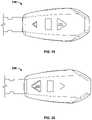
- the trial instrument 200comprises a connector portion 202 , a shaft portion 204 , and a trial head 206 .
- the trial head 206has a size and shape of the spinal fusion implant 10 to be used.
- the trial head 200has a series of windows 208 , 210 , 212 formed within lateral sides 214 . Each window 208 , 210 , 212 preferably extends generally perpendicularly from one lateral side 214 of the trial head 206 to the other.
- the trial instrument 200may be formed of any material that prevents the passage of x-rays therethrough (e.g. titanium). Since the windows extend completely through the trial head 206 , the x-rays are able to pass through and both the size and shape of the windows 208 , 210 , 212 are discernable under fluoroscopy. In the example shown here, the trial head 206 is provided with three windows, however any number may be used. By way of example, the trial head 206 has a proximal shaped window 208 , a distal shaped window 210 , and a central shaped window 212 . The shaped windows 208 , 210 , 212 are arranged linearly along the axis of the trial inserter 20 .
- any material that prevents the passage of x-rays therethroughe.g. titanium. Since the windows extend completely through the trial head 206 , the x-rays are able to pass through and both the size and shape of the windows 208 , 210 , 212 are
- the central window 212is shown as having a generally rectangular shape, however other shapes are possible.
- the central window 212comprises an aperture having a longitudinal axis that is perpendicular to the longitudinal axis of the trial inserter 200 .
- the proximal and distal shaped windowsare positioned on either side (proximal side and distal side, respectively) of the central window 212 .
- the proximal shaped window 208has a generally triangular shape and is arranged to “point” in a proximal direction.
- the distal shaped window 210also has a generally triangular shape and is arranged to “point” in a distal direction.
- the proximal and distal shaped windows 208 , 210comprise apertures having co-planar non-parallel longitudinal axes.
- the axes of the proximal and distal shaped windows 208 , 210are divergent from one another and the central axis. This allows for rapid visual determination of rotational positioning of the trial head 206 , and also for immediate instruction on how to correct improper positioning.
- the parallax distortion of the fluoroscopic imageis minimal when the trial head 206 is centered within the image and therefore the x-rays travel within a directly parallel manner. Because metal prevents the passage of x-rays, a window will appear smaller if it is not directly aligned with the direction of the x-rays.
- one windowe.g. the central shaped window 212
- one windowe.g. the distal shaped window 208
- one windowe.g. the proximal shaped window 210
- the userimmediately knows whether the trial instrument 200 is “hyper-oblique” or “hypo-oblique”, he/she also immediately knows the direction to move his/her hand to get the correct placement of the trial head 206 , thereby decreasing the need for trial inserter repositioning and localizing x-rays thus reducing x-ray fluoroscopic exposure for user and patient.
- the proximal and distal shaped windows 208 , 210will appear the same size under fluoroscopy. However when one of the proximal and distal shaped windows 208 , 210 is larger than the other, the surgeon/user knows that the trial is not correctly positioned.
- FIG. 19is an example of a “hyper-oblique” trial head 206 .
- the distal shaped window 210is larger than the proximal shaped window 208 , indicating suboptimal positioning of the trial 200 . Pivoting the trial 200 in the direction of the distal shaped window 210 will bring the trial head 206 into ideal trial positioning.
- FIG. 20is an example of a “hypo-oblique” trial head 206 .
- the proximal shaped window 208is larger than the distal shaped window 210 , also indicating suboptimal positioning in the trial 200 . Pivoting the trial 200 in the direction of the proximal shaped window 208 will bring the trial head 206 into ideal trial positioning.
- the spinal fusion implant 10is capable of being used in minimally invasive surgical procedures, needing only a relatively small operative corridor for insertion.
- the spinal fusion implant 10will now be described in relation to a transforaminal lumbar interbody fusion (TLIF) technique, in which the intervertebral disc space is approached from a postero-lateral direction, however it should be understood that the spinal fusion implant 10 is capable of use in a variety of surgical procedures not described herein.
- TLIFtransforaminal lumbar interbody fusion
- a trial insertere.g. the trial inserter of FIGS. 17-20
- the spinal fusion implant 10is mated to an insertion device (e.g. insertion instrument 100 ) and advanced through the operative corridor toward the target intervertebral space.
- the spinal fusion implant 10may be oriented with the lateral sides 16 , 18 facing in a caudad/cephalad direction, for example with the first lateral side 16 facing a caudad (inferior) direction and the second lateral side 18 facing a cephalad (superior) direction.
- each of the pair of first tapered surfaces 54will come into contact with one of the adjacent vertebral bodies.
- the pair of first tapered surfaces 54will serve to distract the vertebral bodies, allowing the implant to fully enter the intervertebral space.
- the spinal fusion implant 10should advance with relative ease into the disc space once the adjacent vertebral bodies have been distracted. Once the implant 10 has been positioned in its desired location, the user will then rotate the implant 90° such that the top and bottom surfaces 12 , 14 face in a caudad/cephalad direction and the anti-migration features 24 engage the vertebral bodies.
- the direction of rotationis critical to ensure proper placement of the implant 10 such that the edges of the proximal surface 40 rest on the cortical ring of the vertebral bodies, that the proximal surface 40 does not protrude into the spinal canal, and the implant 10 tapers in the appropriate direction (e.g.
- the spinal fusion implant 10approaches a patient's spine posteriorly from the right with the (longer) first lateral side 16 facing caudally, then implant 10 must be rotated in a counter-clockwise direction to achieve proper positioning.
- implant 10approaches a patient's spine posteriorly from the left side with the (longer) first lateral side 16 facing caudally, then implant 10 must be rotated in a clockwise direction to achieve proper positioning.
- the implantmay include one or more markings or other indicia to help facilitate the proper positioning.
- the first lateral side 16may be marked with “lateral” to indicate that it should face to the exterior of the disc space
- the second lateral side 17may be marked with “medial” to indicate that it should face the interior of the disc space when the implant 10 is rotated into position.
- FIG. 21 Adepicts a spinal fusion implant 10 positioned in the intervertebral disc space, however not in the desired oblique alignment.
- radiographic markers 28 , 30will appear spaced apart from radiographic marker 32 on lateral fluoroscopy.
- FIG. 22 Adepicts a spinal fusion implant 10 positioned in the intervertebral disc space, in the desired oblique alignment.
- radiographic markers 32will appear to align with radiographic marker 32 on lateral fluoroscopy.
Landscapes
- Health & Medical Sciences (AREA)
- Engineering & Computer Science (AREA)
- Biomedical Technology (AREA)
- Orthopedic Medicine & Surgery (AREA)
- Transplantation (AREA)
- Neurology (AREA)
- Veterinary Medicine (AREA)
- Oral & Maxillofacial Surgery (AREA)
- Heart & Thoracic Surgery (AREA)
- Vascular Medicine (AREA)
- Life Sciences & Earth Sciences (AREA)
- Animal Behavior & Ethology (AREA)
- General Health & Medical Sciences (AREA)
- Public Health (AREA)
- Cardiology (AREA)
- Physical Education & Sports Medicine (AREA)
- Prostheses (AREA)
- Physics & Mathematics (AREA)
- General Engineering & Computer Science (AREA)
- Automation & Control Theory (AREA)
- Combustion & Propulsion (AREA)
- Mechanical Engineering (AREA)
- Chemical & Material Sciences (AREA)
- General Physics & Mathematics (AREA)
- Theoretical Computer Science (AREA)
- Remote Sensing (AREA)
- Fluid Mechanics (AREA)
- Computer Networks & Wireless Communication (AREA)
- Signal Processing (AREA)
Abstract
Description
Claims (18)
Priority Applications (3)
| Application Number | Priority Date | Filing Date | Title |
|---|---|---|---|
| US16/416,543US11497621B2 (en) | 2014-01-14 | 2019-05-20 | Inserter for implanting a spinal implant |
| US18/045,480US12127948B2 (en) | 2014-01-14 | 2022-10-11 | System for implanting a spinal fusion implant and related methods |
| US18/895,698US20250017739A1 (en) | 2014-01-14 | 2024-09-25 | System for implanting a spinal fusion implant and related methods |
Applications Claiming Priority (5)
| Application Number | Priority Date | Filing Date | Title |
|---|---|---|---|
| US201461927421P | 2014-01-14 | 2014-01-14 | |
| US201462009647P | 2014-06-09 | 2014-06-09 | |
| US14/597,085US9730802B1 (en) | 2014-01-14 | 2015-01-14 | Spinal fusion implant and related methods |
| US15/677,981US10335287B2 (en) | 2014-01-14 | 2017-08-15 | Spinal fusion implant and related methods |
| US16/416,543US11497621B2 (en) | 2014-01-14 | 2019-05-20 | Inserter for implanting a spinal implant |
Related Parent Applications (2)
| Application Number | Title | Priority Date | Filing Date |
|---|---|---|---|
| US15/667,981ContinuationUS10620645B2 (en) | 2017-08-03 | 2017-08-03 | Microzone HVAC system with precision air device |
| US15/677,981ContinuationUS10335287B2 (en) | 2014-01-14 | 2017-08-15 | Spinal fusion implant and related methods |
Related Child Applications (1)
| Application Number | Title | Priority Date | Filing Date |
|---|---|---|---|
| US18/045,480ContinuationUS12127948B2 (en) | 2014-01-14 | 2022-10-11 | System for implanting a spinal fusion implant and related methods |
Publications (2)
| Publication Number | Publication Date |
|---|---|
| US20190271997A1 US20190271997A1 (en) | 2019-09-05 |
| US11497621B2true US11497621B2 (en) | 2022-11-15 |
Family
ID=59561057
Family Applications (5)
| Application Number | Title | Priority Date | Filing Date |
|---|---|---|---|
| US14/597,085ActiveUS9730802B1 (en) | 2014-01-14 | 2015-01-14 | Spinal fusion implant and related methods |
| US15/677,981Active2035-05-22US10335287B2 (en) | 2014-01-14 | 2017-08-15 | Spinal fusion implant and related methods |
| US16/416,543Active2035-09-10US11497621B2 (en) | 2014-01-14 | 2019-05-20 | Inserter for implanting a spinal implant |
| US18/045,480ActiveUS12127948B2 (en) | 2014-01-14 | 2022-10-11 | System for implanting a spinal fusion implant and related methods |
| US18/895,698PendingUS20250017739A1 (en) | 2014-01-14 | 2024-09-25 | System for implanting a spinal fusion implant and related methods |
Family Applications Before (2)
| Application Number | Title | Priority Date | Filing Date |
|---|---|---|---|
| US14/597,085ActiveUS9730802B1 (en) | 2014-01-14 | 2015-01-14 | Spinal fusion implant and related methods |
| US15/677,981Active2035-05-22US10335287B2 (en) | 2014-01-14 | 2017-08-15 | Spinal fusion implant and related methods |
Family Applications After (2)
| Application Number | Title | Priority Date | Filing Date |
|---|---|---|---|
| US18/045,480ActiveUS12127948B2 (en) | 2014-01-14 | 2022-10-11 | System for implanting a spinal fusion implant and related methods |
| US18/895,698PendingUS20250017739A1 (en) | 2014-01-14 | 2024-09-25 | System for implanting a spinal fusion implant and related methods |
Country Status (1)
| Country | Link |
|---|---|
| US (5) | US9730802B1 (en) |
Families Citing this family (37)
| Publication number | Priority date | Publication date | Assignee | Title |
|---|---|---|---|---|
| WO2006058221A2 (en) | 2004-11-24 | 2006-06-01 | Abdou Samy M | Devices and methods for inter-vertebral orthopedic device placement |
| US8906028B2 (en) | 2009-09-18 | 2014-12-09 | Spinal Surgical Strategies, Llc | Bone graft delivery device and method of using the same |
| US10245159B1 (en) | 2009-09-18 | 2019-04-02 | Spinal Surgical Strategies, Llc | Bone graft delivery system and method for using same |
| US10973656B2 (en) | 2009-09-18 | 2021-04-13 | Spinal Surgical Strategies, Inc. | Bone graft delivery system and method for using same |
| US8764806B2 (en) | 2009-12-07 | 2014-07-01 | Samy Abdou | Devices and methods for minimally invasive spinal stabilization and instrumentation |
| US8845728B1 (en) | 2011-09-23 | 2014-09-30 | Samy Abdou | Spinal fixation devices and methods of use |
| US20130226240A1 (en) | 2012-02-22 | 2013-08-29 | Samy Abdou | Spinous process fixation devices and methods of use |
| US9198767B2 (en) | 2012-08-28 | 2015-12-01 | Samy Abdou | Devices and methods for spinal stabilization and instrumentation |
| US9987142B2 (en) | 2012-08-31 | 2018-06-05 | Institute for Musculoskeletal Science and Education, Ltd. | Fixation devices for anterior lumbar or cervical interbody fusion |
| US9320617B2 (en) | 2012-10-22 | 2016-04-26 | Cogent Spine, LLC | Devices and methods for spinal stabilization and instrumentation |
| US9801734B1 (en)* | 2013-08-09 | 2017-10-31 | Nuvasive, Inc. | Lordotic expandable interbody implant |
| US9730802B1 (en) | 2014-01-14 | 2017-08-15 | Nuvasive, Inc. | Spinal fusion implant and related methods |
| US10857003B1 (en) | 2015-10-14 | 2020-12-08 | Samy Abdou | Devices and methods for vertebral stabilization |
| US10292834B2 (en)* | 2016-06-27 | 2019-05-21 | Globus Medical, Inc. | Intervertebral spacer with chamfered edges |
| US10292825B2 (en)* | 2016-06-27 | 2019-05-21 | Globus Medical, Inc. | Intervertebral spacer with chamfered edges |
| US10307265B2 (en) | 2016-10-18 | 2019-06-04 | Institute for Musculoskeletal Science and Education, Ltd. | Implant with deployable blades |
| US10405992B2 (en) | 2016-10-25 | 2019-09-10 | Institute for Musculoskeletal Science and Education, Ltd. | Spinal fusion implant |
| US10973648B1 (en) | 2016-10-25 | 2021-04-13 | Samy Abdou | Devices and methods for vertebral bone realignment |
| US10449060B2 (en)* | 2016-10-25 | 2019-10-22 | Institute for Musculoskeletal Science and Education, Ltd. | Spinal fusion implant |
| US10744000B1 (en) | 2016-10-25 | 2020-08-18 | Samy Abdou | Devices and methods for vertebral bone realignment |
| US10624760B2 (en)* | 2017-05-22 | 2020-04-21 | Warsaw Orthopedic, Inc. | Spinal implant system and method |
| US10575962B2 (en)* | 2017-11-20 | 2020-03-03 | Warsaw Orthopedic, Inc. | Spinal implant |
| CN108210131B (en)* | 2018-03-12 | 2024-05-31 | 北京理贝尔生物工程研究所有限公司 | Grab for TLIF operation |
| US10736756B2 (en) | 2018-03-30 | 2020-08-11 | Warsaw Orthopedic, Inc. | Radiolucent trial |
| US10537447B2 (en)* | 2018-03-30 | 2020-01-21 | Warsaw Orthopedic, Inc. | Radiolucent trial |
| US10849758B2 (en) | 2018-08-22 | 2020-12-01 | Institute for Musculoskeletal Science and Education, Ltd. | Spinal fusion implant |
| US11179248B2 (en) | 2018-10-02 | 2021-11-23 | Samy Abdou | Devices and methods for spinal implantation |
| FR3094203B1 (en)* | 2019-03-26 | 2021-03-05 | Orthopaedic & Spine Dev Osd | Interbody prosthesis with lateral introduction |
| US11759333B2 (en)* | 2019-10-11 | 2023-09-19 | Warsaw Orthopedic, Inc. | Spinal implant system and methods of use |
| US11278420B2 (en) | 2019-10-25 | 2022-03-22 | Zavation, Llc | Recessed pocket spinal implant |
| US11357645B2 (en) | 2020-04-17 | 2022-06-14 | Warsaw Orthopedic, Inc. | Implant with graded radiopacity calibration feature |
| US11166825B1 (en) | 2020-07-01 | 2021-11-09 | Warsaw Orthopedic, Inc. | Spinal implant |
| JP2024517211A (en) | 2021-05-14 | 2024-04-19 | ニューヴェイジヴ,インコーポレイテッド | Inserter for spinal fusion implants |
| WO2023285675A1 (en) | 2021-07-16 | 2023-01-19 | Blue Ocean Spine Gmbh | Adjustable intervertebral cage, associated instrument and manufacturing process therefor |
| AU2021221798B2 (en)* | 2021-08-25 | 2025-06-19 | 3Dmorphic Pty Ltd | Integrally formed medical devices |
| CN113855201A (en)* | 2021-09-16 | 2021-12-31 | 天津正天医疗器械有限公司 | Endoscopic lumbar intervertebral implant and use method thereof |
| US12167969B2 (en) | 2022-06-24 | 2024-12-17 | Nuvasive, Inc. | Resonating implant systems and methods |
Citations (195)
| Publication number | Priority date | Publication date | Assignee | Title |
|---|---|---|---|---|
| WO1990000037A1 (en) | 1988-06-28 | 1990-01-11 | Michelson Gary K | Artificial spinal fusion implants |
| US5015247A (en) | 1988-06-13 | 1991-05-14 | Michelson Gary K | Threaded spinal implant |
| US5443514A (en)* | 1993-10-01 | 1995-08-22 | Acromed Corporation | Method for using spinal implants |
| WO1995026164A1 (en) | 1994-03-28 | 1995-10-05 | Michelson Gary K | Apparatus, instrumentation and method for spinal fixation |
| CA1337842C (en) | 1988-06-28 | 1996-01-02 | Gary Karlin Michelson | Artificial spinal fusion implants |
| CA2168835A1 (en) | 1992-10-29 | 1996-08-18 | Gary Karlin Michelson | Interbody spinal fusion implants |
| CA2447257A1 (en) | 1995-06-07 | 1996-12-19 | Gary Karlin Michelson | Modular lordotic interbody spinal fusion implant |
| WO1996039988A2 (en) | 1995-06-07 | 1996-12-19 | Michelson Gary K | Translateral spinal implant |
| USD377095S (en) | 1994-06-03 | 1996-12-31 | Sofamor Danek Properties, Inc. | Interbody spinal implant |
| USD377096S (en) | 1994-06-03 | 1996-12-31 | Sofamor Danek Properties, Inc. | Interbody spinal implant |
| USD377527S (en) | 1994-06-03 | 1997-01-21 | Sofamor Danek Group, Inc. | Artificial spinal infusion implant |
| US5609635A (en) | 1988-06-28 | 1997-03-11 | Michelson; Gary K. | Lordotic interbody spinal fusion implants |
| US5653762A (en)* | 1994-03-18 | 1997-08-05 | Pisharodi; Madhavan | Method of stabilizing adjacent vertebrae with rotating, lockable, middle-expanded intervertebral disk stabilizer |
| US5658337A (en) | 1994-05-23 | 1997-08-19 | Spine-Tech, Inc. | Intervertebral fusion implant |
| USD392387S (en) | 1995-06-07 | 1998-03-17 | Gary Karlin Michelson | Lordotic artificial spinal fusion implant |
| US5772661A (en) | 1988-06-13 | 1998-06-30 | Michelson; Gary Karlin | Methods and instrumentation for the surgical correction of human thoracic and lumbar spinal disease from the antero-lateral aspect of the spine |
| US5860973A (en) | 1995-02-27 | 1999-01-19 | Michelson; Gary Karlin | Translateral spinal implant |
| US5885299A (en)* | 1994-09-15 | 1999-03-23 | Surgical Dynamics, Inc. | Apparatus and method for implant insertion |
| US5888224A (en)* | 1993-09-21 | 1999-03-30 | Synthesis (U.S.A.) | Implant for intervertebral space |
| US5961554A (en) | 1996-12-31 | 1999-10-05 | Janson; Frank S | Intervertebral spacer |
| WO2000023015A1 (en) | 1998-10-22 | 2000-04-27 | Sdgi Holdings, Inc. | Artificial intervertebral joint permitting translational and rotational motion |
| US6066174A (en) | 1995-10-16 | 2000-05-23 | Sdgi Holdings, Inc. | Implant insertion device |
| USD425989S (en) | 1996-07-15 | 2000-05-30 | Sofamor Danek Holdings, Inc. | Artificial spinal fusion implant |
| US6113602A (en)* | 1999-03-26 | 2000-09-05 | Sulzer Spine-Tech Inc. | Posterior spinal instrument guide and method |
| US6120502A (en) | 1988-06-13 | 2000-09-19 | Michelson; Gary Karlin | Apparatus and method for the delivery of electrical current for interbody spinal arthrodesis |
| US6123705A (en) | 1988-06-13 | 2000-09-26 | Sdgi Holdings, Inc. | Interbody spinal fusion implants |
| US6136001A (en) | 1994-03-28 | 2000-10-24 | Michelson; Gary Karlin | Apparatus and method for linking spinal implants |
| US6139551A (en) | 1995-06-07 | 2000-10-31 | Sdgi Holdings, Inc. | Anterior spinal instrumentation and method for implantation and revision |
| USD437055S1 (en) | 1999-12-09 | 2001-01-30 | Gary K. Michelson | Trailing end of a spinal implant |
| US6210412B1 (en) | 1988-06-13 | 2001-04-03 | Gary Karlin Michelson | Method for inserting frusto-conical interbody spinal fusion implants |
| US6241770B1 (en) | 1999-03-05 | 2001-06-05 | Gary K. Michelson | Interbody spinal fusion implant having an anatomically conformed trailing end |
| US6290724B1 (en) | 1998-05-27 | 2001-09-18 | Nuvasive, Inc. | Methods for separating and stabilizing adjacent vertebrae |
| WO2001080784A1 (en) | 2000-04-19 | 2001-11-01 | Michelson Gary K | Hemi-lumbar interbody spinal implant having an asymmetrical leading end and method for installation thereof |
| US6350283B1 (en) | 2000-04-19 | 2002-02-26 | Gary K. Michelson | Bone hemi-lumbar interbody spinal implant having an asymmetrical leading end and method of installation thereof |
| US6395031B1 (en) | 1998-10-29 | 2002-05-28 | Sdgi Holdings, Inc. | Expandable intervertebral spacers |
| USD460189S1 (en) | 1999-12-09 | 2002-07-09 | Gary K. Michelson | Trailing end of a spinal implant |
| US6423095B1 (en) | 1995-10-16 | 2002-07-23 | Sdgi Holdings, Inc. | Intervertebral spacers |
| USD463560S1 (en) | 2000-01-03 | 2002-09-24 | Gary K. Michelson | End cap for a spinal implant |
| WO2002078514A2 (en) | 2001-04-02 | 2002-10-10 | Michelson Gary K | Contoured spinal fusion implants |
| US6485517B1 (en) | 1999-05-05 | 2002-11-26 | Gary K. Michelson | Nested interbody spinal fusion implants |
| US6500205B1 (en) | 2000-04-19 | 2002-12-31 | Gary K. Michelson | Expandable threaded arcuate interbody spinal fusion implant with cylindrical configuration during insertion |
| US6520967B1 (en) | 1999-10-20 | 2003-02-18 | Cauthen Research Group, Inc. | Spinal implant insertion instrument for spinal interbody prostheses |
| US6527773B1 (en) | 1999-10-07 | 2003-03-04 | Osteotech, Inc. | Cervical dowel and insertion tool |
| US6537320B1 (en) | 1998-10-30 | 2003-03-25 | Gary K. Michelson | Self-broaching, rotatable, push-in interbody spinal fusion implant and method for deployment thereof |
| US6558423B1 (en) | 1999-05-05 | 2003-05-06 | Gary K. Michelson | Interbody spinal fusion implants with multi-lock for locking opposed screws |
| US6572654B1 (en) | 2000-10-04 | 2003-06-03 | Albert N. Santilli | Intervertebral spacer |
| US6575899B1 (en) | 1999-10-20 | 2003-06-10 | Sdgi Holdings, Inc. | Methods and instruments for endoscopic interbody surgical techniques |
| US20030130667A1 (en) | 2000-05-05 | 2003-07-10 | Osteotech, Inc. | Intervertebral distractor and implant insertion instrument |
| US6595995B2 (en)* | 1995-03-27 | 2003-07-22 | Sdgi Holdings, Inc. | Methods and instruments for interbody fusion |
| US6599291B1 (en) | 2000-10-20 | 2003-07-29 | Sdgi Holdings, Inc. | Methods and instruments for interbody surgical techniques |
| US6610065B1 (en) | 1998-10-28 | 2003-08-26 | Sdgi Holdings, Inc. | Interbody fusion implants and instrumentation |
| US20030195632A1 (en) | 2001-02-06 | 2003-10-16 | Foley Kevin T. | Spinal implant with attached ligament |
| US20040078079A1 (en)* | 2002-10-21 | 2004-04-22 | Foley Kevin T. | Systems and techniques for restoring and maintaining intervertebral anatomy |
| US20040102847A1 (en) | 2002-08-20 | 2004-05-27 | Showa Ika Kohgyo Co., Ltd | Intervertebral spacer |
| US6746454B2 (en)* | 2000-11-07 | 2004-06-08 | Osteotech, Inc. | Implant insertion tool |
| US6758849B1 (en) | 1995-02-17 | 2004-07-06 | Sdgi Holdings, Inc. | Interbody spinal fusion implants |
| US20040162616A1 (en)* | 2002-10-21 | 2004-08-19 | Simonton T. Andrew | Systems and techniques for restoring and maintaining intervertebral anatomy |
| US20040186572A1 (en) | 2002-12-19 | 2004-09-23 | Co-Linge Ag | Pair of lumbar interbody implants and method of fusing together adjoining vertebrae bodies |
| US6830570B1 (en) | 1999-10-21 | 2004-12-14 | Sdgi Holdings, Inc. | Devices and techniques for a posterior lateral disc space approach |
| US20050027360A1 (en) | 2003-08-01 | 2005-02-03 | Webb Scott A. | Spinal implant |
| US20050070900A1 (en) | 2003-09-30 | 2005-03-31 | Depuy Acromed, Inc. | Vertebral fusion device and method for using same |
| US20050096745A1 (en) | 2003-10-29 | 2005-05-05 | Eurosurgical Sa | Intersomatic cage for lumbar fusion by transforaminal approach and its cage carrying device |
| US20050267578A1 (en) | 2000-06-13 | 2005-12-01 | Michelson Gary K | Ratcheted bone dowel having smooth sides and method for use thereof |
| US7008453B1 (en) | 2000-02-04 | 2006-03-07 | Sdgi Holdings, Inc. | Expandable push-in arcuate interbody spinal fusion implant with cylindrical configuration during insertion |
| US20060129238A1 (en)* | 2004-10-26 | 2006-06-15 | Adam Paltzer | Spinal stabilization device and methods |
| US7070598B2 (en) | 2002-06-25 | 2006-07-04 | Sdgi Holdings, Inc. | Minimally invasive expanding spacer and method |
| US20060167548A1 (en) | 2000-08-23 | 2006-07-27 | Jackson Roger P | Non-linear spinal fusion interbody spacer |
| US7087055B2 (en) | 2002-06-25 | 2006-08-08 | Sdgi Holdings, Inc. | Minimally invasive expanding spacer and method |
| US7094239B1 (en) | 1999-05-05 | 2006-08-22 | Sdgi Holdings, Inc. | Screws of cortical bone and method of manufacture thereof |
| US20060195190A1 (en) | 2003-06-24 | 2006-08-31 | Beat Lechmann | Implant for intervertebral space |
| US7115143B1 (en) | 1999-12-08 | 2006-10-03 | Sdgi Holdings, Inc. | Orthopedic implant surface configuration |
| US20070162138A1 (en) | 2005-12-12 | 2007-07-12 | Sdgi Holdings, Inc. | Vertebral implant and insertion tool |
| US20070173857A1 (en) | 2006-01-26 | 2007-07-26 | Sdgi Holdings, Inc. | Surgical tool and method employing vacuum coupling or magnetic coupling engagement mechanism for facilitating positioning of an intervertebral device |
| US7291149B1 (en) | 1995-06-07 | 2007-11-06 | Warsaw Orthopedic, Inc. | Method for inserting interbody spinal fusion implants |
| US20070260315A1 (en) | 2006-05-03 | 2007-11-08 | Foley Kevin T | Devices and methods for disc height restoration |
| US7326248B2 (en) | 2001-03-09 | 2008-02-05 | Warsaw Orthopedic, Inc. | Expandable interbody spinal fusion implant with expansion constraining member and method for use thereof |
| US7354452B2 (en) | 2001-02-06 | 2008-04-08 | Warsaw Orthopedic, Inc. | Spinal bone implant |
| AU2008202022A1 (en) | 1999-05-05 | 2008-05-29 | Warsaw Orthopedic, Inc. | Interbody spinal fusion implants |
| US20080221695A1 (en)* | 2007-03-01 | 2008-09-11 | Jacofsky Marc C | Spinal interbody spacer device |
| US20080269756A1 (en)* | 2007-04-27 | 2008-10-30 | Spinemedica, Inc. | Surgical instruments for spinal disc implants and related methods |
| US7452359B1 (en) | 1988-06-13 | 2008-11-18 | Warsaw Orthopedic, Inc. | Apparatus for inserting spinal implants |
| US7462195B1 (en) | 2000-04-19 | 2008-12-09 | Warsaw Orthopedic, Inc. | Artificial lumbar interbody spinal implant having an asymmetrical leading end |
| US7470273B2 (en) | 2004-06-25 | 2008-12-30 | Ebi, Llc | Tool for intervertebral implant manipulation |
| US7491205B1 (en) | 1988-06-13 | 2009-02-17 | Warsaw Orthopedic, Inc. | Instrumentation for the surgical correction of human thoracic and lumbar spinal disease from the lateral aspect of the spine |
| US20090062917A1 (en) | 2007-08-27 | 2009-03-05 | Foley Kevin T | Spinal interbody replacement devices |
| US7503935B2 (en) | 2003-12-02 | 2009-03-17 | Kyphon Sarl | Method of laterally inserting an artificial vertebral disk replacement with translating pivot point |
| US20090112220A1 (en)* | 2007-10-30 | 2009-04-30 | Kilian Kraus | Manipulating Tool for a Medical Implant, Medical Implant and Kit of Parts Comprising a Manipulating Tool and Implant |
| US7534254B1 (en) | 1988-06-13 | 2009-05-19 | Warsaw Orthopedic, Inc. | Threaded frusto-conical interbody spinal fusion implants |
| US20090187246A1 (en) | 2008-01-22 | 2009-07-23 | Foley Kevin T | Interbody implants for spinal alignment procedures |
| US20090187247A1 (en) | 2008-01-23 | 2009-07-23 | Metcalf Jr Newton H | Spinal implant having a resorbable anchor device for temporarily securing an interbody device to adjacent upper and lower vertebrae |
| US7578820B2 (en) | 2003-09-02 | 2009-08-25 | Moore Jeffrey D | Devices and techniques for a minimally invasive disc space preparation and implant insertion |
| US7594919B2 (en) | 2004-07-23 | 2009-09-29 | Warsaw Orthopedic, Inc. | Artificial disc inserter |
| US7608107B2 (en) | 2000-07-07 | 2009-10-27 | Warsaw Orthopedic, Inc. | Expandable implant with interlocking walls and method for use thereof |
| US7608105B2 (en) | 1994-09-15 | 2009-10-27 | Howmedica Osteonics Corp. | Methods of inserting conically-shaped fusion cages |
| US20090270989A1 (en) | 2007-11-19 | 2009-10-29 | Magellan Spine Technologies, Inc. | Spinal implants and methods |
| US20090276048A1 (en) | 2007-05-08 | 2009-11-05 | Chirico Paul E | Devices and method for bilateral support of a compression-fractured vertebral body |
| US7618423B1 (en) | 2002-06-15 | 2009-11-17 | Nuvasive, Inc. | System and method for performing spinal fusion |
| US20100114105A1 (en)* | 2008-10-31 | 2010-05-06 | Robert Reid,Inc. | System and method for vertebral interbody fusion |
| US20100152857A1 (en) | 2007-08-31 | 2010-06-17 | University Of South Florida | Asymmetric Disc Distracting Cage |
| US20100204798A1 (en) | 2005-10-21 | 2010-08-12 | Stryker Spine | System and method for fusion cage implantation |
| US7776049B1 (en) | 2002-10-02 | 2010-08-17 | Nuvasive, Inc. | Spinal implant inserter, implant, and method |
| US7815682B1 (en) | 2005-09-24 | 2010-10-19 | Nuvasive, Inc. | Spinal fusion implant and related methods |
| US7867277B1 (en) | 2005-07-15 | 2011-01-11 | Nuvasive Inc. | Spinal fusion implant and related methods |
| DE102010023437A1 (en) | 2009-06-20 | 2011-01-27 | Human Tech Germany Gmbh | Form-fit and/or force-fit connection for connecting implant or workpiece with instrument for insertion of implant or workpiece in body, has male counter part consisting of spreader roll pressed in female opening |
| US7901458B2 (en) | 2005-12-16 | 2011-03-08 | Warsaw Orthopedic, Inc. | Intervertebral spacer and insertion tool |
| US7905886B1 (en) | 2003-07-07 | 2011-03-15 | Nuvasive Inc. | System and methods for performing transforaminal lumbar interbody fusion |
| US20110071637A1 (en) | 2000-09-08 | 2011-03-24 | Muhanna Nabil L | System and methods for inserting a vertebral spacer |
| US20110106261A1 (en)* | 2009-10-30 | 2011-05-05 | Spinefrontier, Inc | System and method for an intervertebral implant assembly |
| US20110166654A1 (en) | 2005-04-08 | 2011-07-07 | G&L Consulting | Spine implant insertion device and method |
| US7976549B2 (en) | 2006-03-23 | 2011-07-12 | Theken Spine, Llc | Instruments for delivering spinal implants |
| US7988699B2 (en) | 2004-10-19 | 2011-08-02 | Warsaw Orthopedic, Inc. | Adjustable instrumentation for spinal implant insertion |
| US20110190892A1 (en)* | 2010-02-01 | 2011-08-04 | X-Spine Systems, Inc. | Spinal implant co-insertion system and method |
| US8002837B2 (en)* | 2006-05-19 | 2011-08-23 | Pioneer Surgical Technology | Spinal stabilization device and methods |
| US20110230969A1 (en) | 2010-02-26 | 2011-09-22 | Lutz Biedermann | Implant for stabilizing bones or vertebrae |
| US20110276139A1 (en) | 2004-02-09 | 2011-11-10 | Depuy Spine, Inc. | Systems and methods for spinal surgery |
| US8070754B2 (en) | 2007-05-31 | 2011-12-06 | Fabian Henry F | Spine surgery method and instrumentation |
| US8097027B2 (en) | 2002-05-06 | 2012-01-17 | Warsaw Orthopedic, Inc. | Minimally invasive instruments and methods for inserting implants |
| US8105383B2 (en) | 2000-06-13 | 2012-01-31 | Warsaw Orthopedic, Inc. | Manufactured bone composite implant shaped to conform to a prepared implantation space |
| US8109935B2 (en) | 2009-05-15 | 2012-02-07 | Musculoskeletal Transplant Foundation | Implant inserter device |
| US8114162B1 (en) | 2006-08-09 | 2012-02-14 | Nuvasive, Inc. | Spinal fusion implant and related methods |
| US8114092B2 (en) | 2007-06-07 | 2012-02-14 | Exactech, Inc. | Inserter for a spinal implant |
| US8114088B2 (en)* | 2008-09-19 | 2012-02-14 | Zimmer Spine, Inc. | Geared spinal implant inserter-distractor |
| US8123757B2 (en) | 2003-12-31 | 2012-02-28 | Depuy Spine, Inc. | Inserter instrument and implant clip |
| US8137403B2 (en) | 2001-04-02 | 2012-03-20 | Warsaw Orthopedic, Inc. | Hemi-interbody spinal fusion implants manufactured from a major long bone ring |
| US20120071977A1 (en)* | 2009-03-12 | 2012-03-22 | Vexim | Apparatus for Bone Restoration of the Spine and Methods of Use |
| US20120078370A1 (en) | 2010-08-31 | 2012-03-29 | James Stephen B | Spinal implants |
| US20120083885A1 (en)* | 2010-09-30 | 2012-04-05 | Stryker Spine | Method of inserting surgical implant with guiding rail |
| US20120143341A1 (en) | 2006-12-12 | 2012-06-07 | Arthrodisc, L.L.C. | Devices and methods for visual differentiation of intervertebral spaces |
| US20120165945A1 (en) | 2008-10-13 | 2012-06-28 | Noah Hansell | Intervertebral Spacer |
| US20120165943A1 (en) | 2009-07-27 | 2012-06-28 | Paolo Mangione | Set comprising an intervertebral implant for immobilising a vertebra with respect to another and an instrument for installing this implant |
| US8221503B2 (en) | 2001-11-09 | 2012-07-17 | Zimmer Spine, Inc. | Spinal implant |
| US8252060B2 (en) | 2009-04-02 | 2012-08-28 | Globus Medical Inc. | Method of installation of intervertebral spacers |
| US8262736B2 (en) | 2001-03-27 | 2012-09-11 | Warsaw Orthopedic, Inc. | Radially expanding implants |
| US8298235B2 (en) | 2004-09-30 | 2012-10-30 | Depuy Spine, Inc. | Instrument and method for the insertion and alignment of an intervertebral implant |
| US8303601B2 (en)* | 2006-06-07 | 2012-11-06 | Stryker Spine | Collet-activated distraction wedge inserter |
| US8308805B2 (en)* | 2010-03-16 | 2012-11-13 | Pinnacle Spine Group, Llc | Methods of delivering an implant to an intervertebral space |
| US20120290094A1 (en) | 2002-06-25 | 2012-11-15 | Warsaw Orthopedic, Inc. | Minimally invasive expanding spacer and method |
| US20130006365A1 (en) | 2010-08-27 | 2013-01-03 | Pepper John R | Methods and Systems for Interbody Implant and Bone Graft Delivery |
| US8349017B2 (en) | 2003-07-21 | 2013-01-08 | Spine Solutions, Inc. | Instruments and method for inserting an intervertebral implant |
| US8377137B2 (en) | 2007-11-05 | 2013-02-19 | Medicrea International | Intervertebral implant to immobilize one vertebra relative to another |
| US8377071B2 (en) | 2004-02-13 | 2013-02-19 | Warsaw Orthopedic, Inc. | Spacer with height and angle adjustments for spacing vertebral members |
| US8382840B2 (en) | 2009-09-03 | 2013-02-26 | Zimmer Spine, Inc. | Spinal implant delivery methods and devices |
| US8409292B2 (en) | 1995-06-07 | 2013-04-02 | Warsaw Orthopedic, Inc. | Spinal fusion implant |
| US8425529B2 (en) | 2010-09-30 | 2013-04-23 | Stryker Spine | Instrument for inserting surgical implant with guiding rail |
| US8454623B2 (en)* | 2009-11-11 | 2013-06-04 | Alphatec Spine, Inc | Instrument for insertion and deployment of features on an implant |
| US8500813B2 (en) | 2006-12-26 | 2013-08-06 | Warsaw Othopedic, Inc. | Minimally invasive spinal distraction devices and methods |
| US8500749B2 (en) | 2011-04-19 | 2013-08-06 | Prescient Surgical Designs, Llc | Apparatus and method for inserting intervertebral implants |
| US20130226244A1 (en) | 2012-02-29 | 2013-08-29 | Daniel Davenport | Implant Inserter |
| US8540725B2 (en) | 2005-04-15 | 2013-09-24 | Roy Lim | Instruments, implants and methods for positioning implants into a spinal disc space |
| US20130282126A1 (en) | 2011-02-23 | 2013-10-24 | Sean Saidha | Expandable interbody fusion implant |
| US8579904B2 (en)* | 2011-04-29 | 2013-11-12 | Medacta International Sa | Instrument for positioning an intervertebral implant for the fusion between two vertebral bodies of a vertebral column |
| US20130320672A1 (en)* | 2012-05-31 | 2013-12-05 | Nordson Corporation | Twist lock connector with reinforcing wing grips and reverse snap assembly |
| US8617244B2 (en) | 2009-06-17 | 2013-12-31 | DePuy Synthes Products, LLC | Intervertebral implant |
| US8623088B1 (en) | 2005-07-15 | 2014-01-07 | Nuvasive, Inc. | Spinal fusion implant and related methods |
| US20140012383A1 (en) | 2011-02-14 | 2014-01-09 | Imds Corporation | Expandable intervertebral implants and instruments |
| US20140031943A1 (en) | 2011-07-14 | 2014-01-30 | Warsaw Orthopedic, Inc. | Vertebral interbody spacer |
| US20140058518A1 (en) | 2008-10-13 | 2014-02-27 | Marcin Niemiec | Articulating Spacer |
| US20140058400A1 (en) | 2005-05-27 | 2014-02-27 | Spinecore, Inc. | Instruments and methods for inserting artificial intervertebral implants |
| US8668741B2 (en) | 2001-01-23 | 2014-03-11 | Warsaw Orthopedic, Inc. | Implant with openings adapted to receive bone screws |
| US20140100662A1 (en) | 2012-10-09 | 2014-04-10 | Titan Spine, Llc | Expandable spinal implant with expansion wedge and anchor |
| US8696752B2 (en) | 2011-12-30 | 2014-04-15 | Metal Industries Research & Development Centre | Interbody cage for spine fusion |
| US8734447B1 (en) | 1988-06-13 | 2014-05-27 | Warsaw Orthopedic, Inc. | Apparatus and method of inserting spinal implants |
| US20140148907A1 (en) | 2006-10-11 | 2014-05-29 | Coridea LLC | Steerable spine implant insertion device and method |
| US8771321B2 (en) | 2001-02-04 | 2014-07-08 | Warsaw Orthopedic, Inc. | Method for loading a spinal implant |
| US8790403B2 (en) | 2006-04-20 | 2014-07-29 | K2M, Inc. | Monorail system |
| US8801721B2 (en) | 2006-08-16 | 2014-08-12 | K2M, Inc. | Apparatus and methods for inserting an implant |
| US8828018B2 (en)* | 2010-12-13 | 2014-09-09 | Ashraf A. Ragab | Bone cage placement device |
| US8845738B2 (en) | 2002-02-02 | 2014-09-30 | Warsaw Orthopedic, Inc. | Spinal implant having deployable bone engaging projections |
| US20140316477A1 (en) | 2007-08-13 | 2014-10-23 | Stryker Spine | Insertion instrument for intervertebral implants |
| US20140330280A1 (en)* | 2013-05-02 | 2014-11-06 | Custom Spine, Inc. | Interbody distractor |
| US8882844B2 (en) | 2008-03-07 | 2014-11-11 | K2M, Inc. | Intervertebral instrument, implant, and method |
| US8882843B2 (en) | 2000-07-10 | 2014-11-11 | Warsaw Orthopedic, Inc. | Interbody spinal fusion implant having a trailing end with at least one stabilization element |
| US20140350682A1 (en) | 2005-05-06 | 2014-11-27 | Titan Spine, Llc | Interbody Spinal Implant Having a Roughened Surface Topography |
| US8926701B2 (en) | 2006-09-13 | 2015-01-06 | DePuy Synthes Products, LLC | Allograft intervertebral implant and method of manufacturing the same |
| US20150012098A1 (en) | 2013-07-03 | 2015-01-08 | Spine Innovation, Inc. | Methods and apparatus for implanting an interbody device |
| US20150012099A1 (en) | 2012-02-08 | 2015-01-08 | Implanet | Intersomatic Implant and Tool for Installing Such an Implant |
| US20150051702A1 (en) | 2012-02-24 | 2015-02-19 | Ldr Medical | Anchoring device and system for an intervertebral implant, intervertebral implant and implantation instrument |
| US20150066145A1 (en) | 2013-08-29 | 2015-03-05 | Andrew Rogers | Expandable and adjustable lordosis interbody fusion system |
| US20150073421A1 (en) | 2012-05-28 | 2015-03-12 | Nlt Spine Ltd. | Surgical impaling member |
| US20150081021A1 (en) | 2012-04-27 | 2015-03-19 | Lfc Spolka Z O.O. | Intervertebral implant, instrument for use in placing it |
| US8986389B2 (en) | 2003-02-03 | 2015-03-24 | Warsaw, Orthopedic, Inc. | Expanding interbody implant and articulating inserter and method |
| US8998920B2 (en) | 2008-12-19 | 2015-04-07 | Amicus Design Group, Llc | Insertion tool for inter-body vertebral prosthetic device with self-deploying screws |
| US20150100129A1 (en) | 2013-10-07 | 2015-04-09 | Warsaw Orthopedic, Inc. | Spinal implant system and method |
| US20150105860A1 (en) | 2006-07-31 | 2015-04-16 | DePuy Synthes Products, LLC | Spinal fusion implant |
| US20150127108A1 (en) | 2001-04-02 | 2015-05-07 | Warsaw Orthopedic, Inc. | Spinal fusion implant with bone screws and a bone screw lock |
| US9028553B2 (en) | 2009-11-05 | 2015-05-12 | DePuy Synthes Products, Inc. | Self-pivoting spinal implant and associated instrumentation |
| US9034043B2 (en)* | 2012-02-03 | 2015-05-19 | Zimmer Spine, Inc. | Intervertebral implant and insertion instrument |
| USD731063S1 (en) | 2009-10-13 | 2015-06-02 | Nuvasive, Inc. | Spinal fusion implant |
| US20150157469A1 (en)* | 2013-11-26 | 2015-06-11 | Xenco Medical LLC | Lock and release implant delivery system |
| US20150257894A1 (en) | 2013-03-15 | 2015-09-17 | Mark M. Levy | Orthopedic expandable devices |
| USD741488S1 (en) | 2006-07-17 | 2015-10-20 | Nuvasive, Inc. | Spinal fusion implant |
| US9241810B1 (en) | 2010-07-12 | 2016-01-26 | Spinesmith Partners, L.P. | Fusion device and associated methods |
| US9248028B2 (en) | 2011-09-16 | 2016-02-02 | DePuy Synthes Products, Inc. | Removable, bone-securing cover plate for intervertebral fusion cage |
| US9248029B2 (en) | 2011-01-06 | 2016-02-02 | Darren L. BERGEY | Interbody vertebral prosthetic device with blade anchor |
| US20170172758A1 (en) | 2015-12-21 | 2017-06-22 | Southern Spine, Llc | Expandable Interbody Devices and Related Instruments and Methods for Spinal Fusion Surgery |
Family Cites Families (7)
| Publication number | Priority date | Publication date | Assignee | Title |
|---|---|---|---|---|
| AU743244B2 (en) | 1994-03-28 | 2002-01-24 | Warsaw Orthopedic, Inc. | Apparatus, instrumentation and method for spinal fixation |
| AU752060B2 (en) | 1995-02-17 | 2002-09-05 | Warsaw Orthopedic, Inc. | Improved interbody spinal fusion implants |
| AU739408B2 (en) | 1995-06-07 | 2001-10-11 | Warsaw Orthopedic, Inc. | Tapered interbody spinal fusion implants |
| AU733248B2 (en) | 1995-06-07 | 2001-05-10 | Warsaw Orthopedic, Inc. | Translateral spinal implant |
| AU733977B2 (en) | 1995-06-07 | 2001-05-31 | Warsaw Orthopedic, Inc. | Lordotic interbody spinal fusion implants |
| AU755184B2 (en) | 1998-10-30 | 2002-12-05 | Warsaw Orthopedic, Inc. | Self-broaching, rotatable, push-in interbody fusion implant and method for deployment thereof |
| US9730802B1 (en) | 2014-01-14 | 2017-08-15 | Nuvasive, Inc. | Spinal fusion implant and related methods |
- 2015
- 2015-01-14USUS14/597,085patent/US9730802B1/enactiveActive
- 2017
- 2017-08-15USUS15/677,981patent/US10335287B2/enactiveActive
- 2019
- 2019-05-20USUS16/416,543patent/US11497621B2/enactiveActive
- 2022
- 2022-10-11USUS18/045,480patent/US12127948B2/enactiveActive
- 2024
- 2024-09-25USUS18/895,698patent/US20250017739A1/enactivePending
Patent Citations (217)
| Publication number | Priority date | Publication date | Assignee | Title |
|---|---|---|---|---|
| US6210412B1 (en) | 1988-06-13 | 2001-04-03 | Gary Karlin Michelson | Method for inserting frusto-conical interbody spinal fusion implants |
| US5772661A (en) | 1988-06-13 | 1998-06-30 | Michelson; Gary Karlin | Methods and instrumentation for the surgical correction of human thoracic and lumbar spinal disease from the antero-lateral aspect of the spine |
| US6123705A (en) | 1988-06-13 | 2000-09-26 | Sdgi Holdings, Inc. | Interbody spinal fusion implants |
| US7491205B1 (en) | 1988-06-13 | 2009-02-17 | Warsaw Orthopedic, Inc. | Instrumentation for the surgical correction of human thoracic and lumbar spinal disease from the lateral aspect of the spine |
| US5785710A (en) | 1988-06-13 | 1998-07-28 | Sofamor Danek Group, Inc. | Interbody spinal fusion implants |
| US5593409A (en) | 1988-06-13 | 1997-01-14 | Sofamor Danek Group, Inc. | Interbody spinal fusion implants |
| US8734447B1 (en) | 1988-06-13 | 2014-05-27 | Warsaw Orthopedic, Inc. | Apparatus and method of inserting spinal implants |
| US6120502A (en) | 1988-06-13 | 2000-09-19 | Michelson; Gary Karlin | Apparatus and method for the delivery of electrical current for interbody spinal arthrodesis |
| US7452359B1 (en) | 1988-06-13 | 2008-11-18 | Warsaw Orthopedic, Inc. | Apparatus for inserting spinal implants |
| US7534254B1 (en) | 1988-06-13 | 2009-05-19 | Warsaw Orthopedic, Inc. | Threaded frusto-conical interbody spinal fusion implants |
| US5015247A (en) | 1988-06-13 | 1991-05-14 | Michelson Gary K | Threaded spinal implant |
| US6478823B1 (en) | 1988-06-28 | 2002-11-12 | Sofamor Danek Holdings, Inc. | Artificial spinal fusion implants |
| WO1990000037A1 (en) | 1988-06-28 | 1990-01-11 | Michelson Gary K | Artificial spinal fusion implants |
| US5609635A (en) | 1988-06-28 | 1997-03-11 | Michelson; Gary K. | Lordotic interbody spinal fusion implants |
| US5776199A (en) | 1988-06-28 | 1998-07-07 | Sofamor Danek Properties | Artificial spinal fusion implants |
| CA1337842C (en) | 1988-06-28 | 1996-01-02 | Gary Karlin Michelson | Artificial spinal fusion implants |
| CA2168835A1 (en) | 1992-10-29 | 1996-08-18 | Gary Karlin Michelson | Interbody spinal fusion implants |
| US5888224A (en)* | 1993-09-21 | 1999-03-30 | Synthesis (U.S.A.) | Implant for intervertebral space |
| US5443514A (en)* | 1993-10-01 | 1995-08-22 | Acromed Corporation | Method for using spinal implants |
| US5653762A (en)* | 1994-03-18 | 1997-08-05 | Pisharodi; Madhavan | Method of stabilizing adjacent vertebrae with rotating, lockable, middle-expanded intervertebral disk stabilizer |
| US6364880B1 (en) | 1994-03-28 | 2002-04-02 | Gary Karlin Michelson | Spinal implant with bone screws |
| WO1995026164A1 (en) | 1994-03-28 | 1995-10-05 | Michelson Gary K | Apparatus, instrumentation and method for spinal fixation |
| US6136001A (en) | 1994-03-28 | 2000-10-24 | Michelson; Gary Karlin | Apparatus and method for linking spinal implants |
| US5658337A (en) | 1994-05-23 | 1997-08-19 | Spine-Tech, Inc. | Intervertebral fusion implant |
| US6605089B1 (en) | 1994-05-27 | 2003-08-12 | Gary Karlin Michelson | Apparatus and method for the delivery of electrical current for interbody spinal arthrodesis |
| USD377095S (en) | 1994-06-03 | 1996-12-31 | Sofamor Danek Properties, Inc. | Interbody spinal implant |
| USD377096S (en) | 1994-06-03 | 1996-12-31 | Sofamor Danek Properties, Inc. | Interbody spinal implant |
| USD377527S (en) | 1994-06-03 | 1997-01-21 | Sofamor Danek Group, Inc. | Artificial spinal infusion implant |
| US7608105B2 (en) | 1994-09-15 | 2009-10-27 | Howmedica Osteonics Corp. | Methods of inserting conically-shaped fusion cages |
| US5885299A (en)* | 1994-09-15 | 1999-03-23 | Surgical Dynamics, Inc. | Apparatus and method for implant insertion |
| US6758849B1 (en) | 1995-02-17 | 2004-07-06 | Sdgi Holdings, Inc. | Interbody spinal fusion implants |
| US5860973A (en) | 1995-02-27 | 1999-01-19 | Michelson; Gary Karlin | Translateral spinal implant |
| US6595995B2 (en)* | 1995-03-27 | 2003-07-22 | Sdgi Holdings, Inc. | Methods and instruments for interbody fusion |
| US6447544B1 (en) | 1995-06-07 | 2002-09-10 | Gary Karlin Michelson | Lordotic interbody spinal fusion implants |
| CA2447257A1 (en) | 1995-06-07 | 1996-12-19 | Gary Karlin Michelson | Modular lordotic interbody spinal fusion implant |
| WO1996039988A2 (en) | 1995-06-07 | 1996-12-19 | Michelson Gary K | Translateral spinal implant |
| US8409292B2 (en) | 1995-06-07 | 2013-04-02 | Warsaw Orthopedic, Inc. | Spinal fusion implant |
| USD392387S (en) | 1995-06-07 | 1998-03-17 | Gary Karlin Michelson | Lordotic artificial spinal fusion implant |
| US6190388B1 (en) | 1995-06-07 | 2001-02-20 | Gary K. Michelson | Anterior spinal instrumentation and method for implantation and revision |
| US8679118B2 (en) | 1995-06-07 | 2014-03-25 | Warsaw Orthopedic, Inc. | Spinal implants |
| US7291149B1 (en) | 1995-06-07 | 2007-11-06 | Warsaw Orthopedic, Inc. | Method for inserting interbody spinal fusion implants |
| US6139551A (en) | 1995-06-07 | 2000-10-31 | Sdgi Holdings, Inc. | Anterior spinal instrumentation and method for implantation and revision |
| US6066174A (en) | 1995-10-16 | 2000-05-23 | Sdgi Holdings, Inc. | Implant insertion device |
| US6423095B1 (en) | 1995-10-16 | 2002-07-23 | Sdgi Holdings, Inc. | Intervertebral spacers |
| US20030060886A1 (en) | 1995-10-16 | 2003-03-27 | Van Hoeck James E. | Intervertebral spacers |
| US8075622B2 (en) | 1995-10-16 | 2011-12-13 | Warsaw Orthopedic, Inc | Intervertebral spacers |
| USD425989S (en) | 1996-07-15 | 2000-05-30 | Sofamor Danek Holdings, Inc. | Artificial spinal fusion implant |
| US5961554A (en) | 1996-12-31 | 1999-10-05 | Janson; Frank S | Intervertebral spacer |
| US6290724B1 (en) | 1998-05-27 | 2001-09-18 | Nuvasive, Inc. | Methods for separating and stabilizing adjacent vertebrae |
| WO2000023015A1 (en) | 1998-10-22 | 2000-04-27 | Sdgi Holdings, Inc. | Artificial intervertebral joint permitting translational and rotational motion |
| US6610065B1 (en) | 1998-10-28 | 2003-08-26 | Sdgi Holdings, Inc. | Interbody fusion implants and instrumentation |
| US6395031B1 (en) | 1998-10-29 | 2002-05-28 | Sdgi Holdings, Inc. | Expandable intervertebral spacers |
| US6537320B1 (en) | 1998-10-30 | 2003-03-25 | Gary K. Michelson | Self-broaching, rotatable, push-in interbody spinal fusion implant and method for deployment thereof |
| US6241770B1 (en) | 1999-03-05 | 2001-06-05 | Gary K. Michelson | Interbody spinal fusion implant having an anatomically conformed trailing end |
| US6113602A (en)* | 1999-03-26 | 2000-09-05 | Sulzer Spine-Tech Inc. | Posterior spinal instrument guide and method |
| US6485517B1 (en) | 1999-05-05 | 2002-11-26 | Gary K. Michelson | Nested interbody spinal fusion implants |
| US6558423B1 (en) | 1999-05-05 | 2003-05-06 | Gary K. Michelson | Interbody spinal fusion implants with multi-lock for locking opposed screws |
| US7094239B1 (en) | 1999-05-05 | 2006-08-22 | Sdgi Holdings, Inc. | Screws of cortical bone and method of manufacture thereof |
| AU2008202022A1 (en) | 1999-05-05 | 2008-05-29 | Warsaw Orthopedic, Inc. | Interbody spinal fusion implants |
| US6527773B1 (en) | 1999-10-07 | 2003-03-04 | Osteotech, Inc. | Cervical dowel and insertion tool |
| US6520967B1 (en) | 1999-10-20 | 2003-02-18 | Cauthen Research Group, Inc. | Spinal implant insertion instrument for spinal interbody prostheses |
| US6575899B1 (en) | 1999-10-20 | 2003-06-10 | Sdgi Holdings, Inc. | Methods and instruments for endoscopic interbody surgical techniques |
| US6830570B1 (en) | 1999-10-21 | 2004-12-14 | Sdgi Holdings, Inc. | Devices and techniques for a posterior lateral disc space approach |
| US7244275B2 (en) | 1999-12-08 | 2007-07-17 | Warsaw Orthopedic, Inc. | Orthopedic implant surface configuration with a projection having a back cut |
| US7115143B1 (en) | 1999-12-08 | 2006-10-03 | Sdgi Holdings, Inc. | Orthopedic implant surface configuration |
| USD437055S1 (en) | 1999-12-09 | 2001-01-30 | Gary K. Michelson | Trailing end of a spinal implant |
| USD460189S1 (en) | 1999-12-09 | 2002-07-09 | Gary K. Michelson | Trailing end of a spinal implant |
| USD463560S1 (en) | 2000-01-03 | 2002-09-24 | Gary K. Michelson | End cap for a spinal implant |
| US7008453B1 (en) | 2000-02-04 | 2006-03-07 | Sdgi Holdings, Inc. | Expandable push-in arcuate interbody spinal fusion implant with cylindrical configuration during insertion |
| US6350283B1 (en) | 2000-04-19 | 2002-02-26 | Gary K. Michelson | Bone hemi-lumbar interbody spinal implant having an asymmetrical leading end and method of installation thereof |
| WO2001080784A1 (en) | 2000-04-19 | 2001-11-01 | Michelson Gary K | Hemi-lumbar interbody spinal implant having an asymmetrical leading end and method for installation thereof |
| US6500205B1 (en) | 2000-04-19 | 2002-12-31 | Gary K. Michelson | Expandable threaded arcuate interbody spinal fusion implant with cylindrical configuration during insertion |
| US7462195B1 (en) | 2000-04-19 | 2008-12-09 | Warsaw Orthopedic, Inc. | Artificial lumbar interbody spinal implant having an asymmetrical leading end |
| US20030130667A1 (en) | 2000-05-05 | 2003-07-10 | Osteotech, Inc. | Intervertebral distractor and implant insertion instrument |
| US20050267578A1 (en) | 2000-06-13 | 2005-12-01 | Michelson Gary K | Ratcheted bone dowel having smooth sides and method for use thereof |
| US8105383B2 (en) | 2000-06-13 | 2012-01-31 | Warsaw Orthopedic, Inc. | Manufactured bone composite implant shaped to conform to a prepared implantation space |
| US7608107B2 (en) | 2000-07-07 | 2009-10-27 | Warsaw Orthopedic, Inc. | Expandable implant with interlocking walls and method for use thereof |
| US8882843B2 (en) | 2000-07-10 | 2014-11-11 | Warsaw Orthopedic, Inc. | Interbody spinal fusion implant having a trailing end with at least one stabilization element |
| US20060167548A1 (en) | 2000-08-23 | 2006-07-27 | Jackson Roger P | Non-linear spinal fusion interbody spacer |
| US20110071637A1 (en) | 2000-09-08 | 2011-03-24 | Muhanna Nabil L | System and methods for inserting a vertebral spacer |
| US6572654B1 (en) | 2000-10-04 | 2003-06-03 | Albert N. Santilli | Intervertebral spacer |
| US6599291B1 (en) | 2000-10-20 | 2003-07-29 | Sdgi Holdings, Inc. | Methods and instruments for interbody surgical techniques |
| US6746454B2 (en)* | 2000-11-07 | 2004-06-08 | Osteotech, Inc. | Implant insertion tool |
| US8668741B2 (en) | 2001-01-23 | 2014-03-11 | Warsaw Orthopedic, Inc. | Implant with openings adapted to receive bone screws |
| US8771321B2 (en) | 2001-02-04 | 2014-07-08 | Warsaw Orthopedic, Inc. | Method for loading a spinal implant |
| US20030195632A1 (en) | 2001-02-06 | 2003-10-16 | Foley Kevin T. | Spinal implant with attached ligament |
| US7354452B2 (en) | 2001-02-06 | 2008-04-08 | Warsaw Orthopedic, Inc. | Spinal bone implant |
| US7326248B2 (en) | 2001-03-09 | 2008-02-05 | Warsaw Orthopedic, Inc. | Expandable interbody spinal fusion implant with expansion constraining member and method for use thereof |
| US8262736B2 (en) | 2001-03-27 | 2012-09-11 | Warsaw Orthopedic, Inc. | Radially expanding implants |
| US8137403B2 (en) | 2001-04-02 | 2012-03-20 | Warsaw Orthopedic, Inc. | Hemi-interbody spinal fusion implants manufactured from a major long bone ring |
| WO2002078514A2 (en) | 2001-04-02 | 2002-10-10 | Michelson Gary K | Contoured spinal fusion implants |
| US20150127108A1 (en) | 2001-04-02 | 2015-05-07 | Warsaw Orthopedic, Inc. | Spinal fusion implant with bone screws and a bone screw lock |
| US8221503B2 (en) | 2001-11-09 | 2012-07-17 | Zimmer Spine, Inc. | Spinal implant |
| US8845738B2 (en) | 2002-02-02 | 2014-09-30 | Warsaw Orthopedic, Inc. | Spinal implant having deployable bone engaging projections |
| US8097027B2 (en) | 2002-05-06 | 2012-01-17 | Warsaw Orthopedic, Inc. | Minimally invasive instruments and methods for inserting implants |
| US7618423B1 (en) | 2002-06-15 | 2009-11-17 | Nuvasive, Inc. | System and method for performing spinal fusion |
| US7070598B2 (en) | 2002-06-25 | 2006-07-04 | Sdgi Holdings, Inc. | Minimally invasive expanding spacer and method |
| US8317798B2 (en) | 2002-06-25 | 2012-11-27 | Warsaw Orthopedic | Minimally invasive expanding spacer and method |
| US7087055B2 (en) | 2002-06-25 | 2006-08-08 | Sdgi Holdings, Inc. | Minimally invasive expanding spacer and method |
| US20120290094A1 (en) | 2002-06-25 | 2012-11-15 | Warsaw Orthopedic, Inc. | Minimally invasive expanding spacer and method |
| US20040102847A1 (en) | 2002-08-20 | 2004-05-27 | Showa Ika Kohgyo Co., Ltd | Intervertebral spacer |
| US7776049B1 (en) | 2002-10-02 | 2010-08-17 | Nuvasive, Inc. | Spinal implant inserter, implant, and method |
| US20150112442A1 (en) | 2002-10-21 | 2015-04-23 | Warsaw Orthopedic, Inc. | Systems and techniques for restoring and maintaining intervertebral anatomy |
| US20040078079A1 (en)* | 2002-10-21 | 2004-04-22 | Foley Kevin T. | Systems and techniques for restoring and maintaining intervertebral anatomy |
| US20040162616A1 (en)* | 2002-10-21 | 2004-08-19 | Simonton T. Andrew | Systems and techniques for restoring and maintaining intervertebral anatomy |
| US20070032872A1 (en) | 2002-10-21 | 2007-02-08 | Warsaw Orthopedic, Inc. (Successor in interest to SDGI Holdings, Inc.) | Systems and techniques for restoring and maintaining intervertebral anatomy |
| US20040186572A1 (en) | 2002-12-19 | 2004-09-23 | Co-Linge Ag | Pair of lumbar interbody implants and method of fusing together adjoining vertebrae bodies |
| US6942697B2 (en) | 2002-12-19 | 2005-09-13 | Co-Ligne Ag | Pair of lumbar interbody implants and method of fusing together adjoining vertebrae bodies |
| US8986389B2 (en) | 2003-02-03 | 2015-03-24 | Warsaw, Orthopedic, Inc. | Expanding interbody implant and articulating inserter and method |
| US8012208B2 (en) | 2003-06-24 | 2011-09-06 | Synthes Usa, Llc | Implant for intervertebral space |
| US20060195190A1 (en) | 2003-06-24 | 2006-08-31 | Beat Lechmann | Implant for intervertebral space |
| US7905886B1 (en) | 2003-07-07 | 2011-03-15 | Nuvasive Inc. | System and methods for performing transforaminal lumbar interbody fusion |
| US8349017B2 (en) | 2003-07-21 | 2013-01-08 | Spine Solutions, Inc. | Instruments and method for inserting an intervertebral implant |
| US20050027360A1 (en) | 2003-08-01 | 2005-02-03 | Webb Scott A. | Spinal implant |
| US7578820B2 (en) | 2003-09-02 | 2009-08-25 | Moore Jeffrey D | Devices and techniques for a minimally invasive disc space preparation and implant insertion |
| US20050070900A1 (en) | 2003-09-30 | 2005-03-31 | Depuy Acromed, Inc. | Vertebral fusion device and method for using same |
| US20050096745A1 (en) | 2003-10-29 | 2005-05-05 | Eurosurgical Sa | Intersomatic cage for lumbar fusion by transforaminal approach and its cage carrying device |
| US7503935B2 (en) | 2003-12-02 | 2009-03-17 | Kyphon Sarl | Method of laterally inserting an artificial vertebral disk replacement with translating pivot point |
| US8123757B2 (en) | 2003-12-31 | 2012-02-28 | Depuy Spine, Inc. | Inserter instrument and implant clip |
| US20110276139A1 (en) | 2004-02-09 | 2011-11-10 | Depuy Spine, Inc. | Systems and methods for spinal surgery |
| US8579907B2 (en) | 2004-02-13 | 2013-11-12 | Warsaw Orthopedic, Inc. | Spacer with height and angle adjustments for spacing vertebral members |
| US8377071B2 (en) | 2004-02-13 | 2013-02-19 | Warsaw Orthopedic, Inc. | Spacer with height and angle adjustments for spacing vertebral members |
| US7470273B2 (en) | 2004-06-25 | 2008-12-30 | Ebi, Llc | Tool for intervertebral implant manipulation |
| US7594919B2 (en) | 2004-07-23 | 2009-09-29 | Warsaw Orthopedic, Inc. | Artificial disc inserter |
| US8298235B2 (en) | 2004-09-30 | 2012-10-30 | Depuy Spine, Inc. | Instrument and method for the insertion and alignment of an intervertebral implant |
| US7988699B2 (en) | 2004-10-19 | 2011-08-02 | Warsaw Orthopedic, Inc. | Adjustable instrumentation for spinal implant insertion |
| US20060129238A1 (en)* | 2004-10-26 | 2006-06-15 | Adam Paltzer | Spinal stabilization device and methods |
| US20110166654A1 (en) | 2005-04-08 | 2011-07-07 | G&L Consulting | Spine implant insertion device and method |
| US8540725B2 (en) | 2005-04-15 | 2013-09-24 | Roy Lim | Instruments, implants and methods for positioning implants into a spinal disc space |
| US20140350682A1 (en) | 2005-05-06 | 2014-11-27 | Titan Spine, Llc | Interbody Spinal Implant Having a Roughened Surface Topography |
| US20140058400A1 (en) | 2005-05-27 | 2014-02-27 | Spinecore, Inc. | Instruments and methods for inserting artificial intervertebral implants |
| US8623088B1 (en) | 2005-07-15 | 2014-01-07 | Nuvasive, Inc. | Spinal fusion implant and related methods |
| US7867277B1 (en) | 2005-07-15 | 2011-01-11 | Nuvasive Inc. | Spinal fusion implant and related methods |
| US7815682B1 (en) | 2005-09-24 | 2010-10-19 | Nuvasive, Inc. | Spinal fusion implant and related methods |
| USD733303S1 (en) | 2005-09-24 | 2015-06-30 | Nuvasive, Inc. | Intervertebral implant |
| US20100204798A1 (en) | 2005-10-21 | 2010-08-12 | Stryker Spine | System and method for fusion cage implantation |
| US20070162138A1 (en) | 2005-12-12 | 2007-07-12 | Sdgi Holdings, Inc. | Vertebral implant and insertion tool |
| US7901458B2 (en) | 2005-12-16 | 2011-03-08 | Warsaw Orthopedic, Inc. | Intervertebral spacer and insertion tool |
| US20070173857A1 (en) | 2006-01-26 | 2007-07-26 | Sdgi Holdings, Inc. | Surgical tool and method employing vacuum coupling or magnetic coupling engagement mechanism for facilitating positioning of an intervertebral device |
| US7976549B2 (en) | 2006-03-23 | 2011-07-12 | Theken Spine, Llc | Instruments for delivering spinal implants |
| US8790403B2 (en) | 2006-04-20 | 2014-07-29 | K2M, Inc. | Monorail system |
| US20070260315A1 (en) | 2006-05-03 | 2007-11-08 | Foley Kevin T | Devices and methods for disc height restoration |
| US8002837B2 (en)* | 2006-05-19 | 2011-08-23 | Pioneer Surgical Technology | Spinal stabilization device and methods |
| US8303601B2 (en)* | 2006-06-07 | 2012-11-06 | Stryker Spine | Collet-activated distraction wedge inserter |
| USD741488S1 (en) | 2006-07-17 | 2015-10-20 | Nuvasive, Inc. | Spinal fusion implant |
| US20150105860A1 (en) | 2006-07-31 | 2015-04-16 | DePuy Synthes Products, LLC | Spinal fusion implant |
| US8114162B1 (en) | 2006-08-09 | 2012-02-14 | Nuvasive, Inc. | Spinal fusion implant and related methods |
| US8801721B2 (en) | 2006-08-16 | 2014-08-12 | K2M, Inc. | Apparatus and methods for inserting an implant |
| US8926701B2 (en) | 2006-09-13 | 2015-01-06 | DePuy Synthes Products, LLC | Allograft intervertebral implant and method of manufacturing the same |
| US20140148907A1 (en) | 2006-10-11 | 2014-05-29 | Coridea LLC | Steerable spine implant insertion device and method |
| US20120143341A1 (en) | 2006-12-12 | 2012-06-07 | Arthrodisc, L.L.C. | Devices and methods for visual differentiation of intervertebral spaces |
| US8500813B2 (en) | 2006-12-26 | 2013-08-06 | Warsaw Othopedic, Inc. | Minimally invasive spinal distraction devices and methods |
| US20080221695A1 (en)* | 2007-03-01 | 2008-09-11 | Jacofsky Marc C | Spinal interbody spacer device |
| US20080269756A1 (en)* | 2007-04-27 | 2008-10-30 | Spinemedica, Inc. | Surgical instruments for spinal disc implants and related methods |
| US20090276048A1 (en) | 2007-05-08 | 2009-11-05 | Chirico Paul E | Devices and method for bilateral support of a compression-fractured vertebral body |
| US8070754B2 (en) | 2007-05-31 | 2011-12-06 | Fabian Henry F | Spine surgery method and instrumentation |
| US8114092B2 (en) | 2007-06-07 | 2012-02-14 | Exactech, Inc. | Inserter for a spinal implant |
| US20140316477A1 (en) | 2007-08-13 | 2014-10-23 | Stryker Spine | Insertion instrument for intervertebral implants |
| US20090062917A1 (en) | 2007-08-27 | 2009-03-05 | Foley Kevin T | Spinal interbody replacement devices |
| US20100152857A1 (en) | 2007-08-31 | 2010-06-17 | University Of South Florida | Asymmetric Disc Distracting Cage |
| US20090112220A1 (en)* | 2007-10-30 | 2009-04-30 | Kilian Kraus | Manipulating Tool for a Medical Implant, Medical Implant and Kit of Parts Comprising a Manipulating Tool and Implant |
| US8377137B2 (en) | 2007-11-05 | 2013-02-19 | Medicrea International | Intervertebral implant to immobilize one vertebra relative to another |
| US20090270989A1 (en) | 2007-11-19 | 2009-10-29 | Magellan Spine Technologies, Inc. | Spinal implants and methods |
| US20090187246A1 (en) | 2008-01-22 | 2009-07-23 | Foley Kevin T | Interbody implants for spinal alignment procedures |
| US20090187247A1 (en) | 2008-01-23 | 2009-07-23 | Metcalf Jr Newton H | Spinal implant having a resorbable anchor device for temporarily securing an interbody device to adjacent upper and lower vertebrae |
| US8882844B2 (en) | 2008-03-07 | 2014-11-11 | K2M, Inc. | Intervertebral instrument, implant, and method |
| US8114088B2 (en)* | 2008-09-19 | 2012-02-14 | Zimmer Spine, Inc. | Geared spinal implant inserter-distractor |
| US20120165945A1 (en) | 2008-10-13 | 2012-06-28 | Noah Hansell | Intervertebral Spacer |
| US20140058518A1 (en) | 2008-10-13 | 2014-02-27 | Marcin Niemiec | Articulating Spacer |
| US20100114105A1 (en)* | 2008-10-31 | 2010-05-06 | Robert Reid,Inc. | System and method for vertebral interbody fusion |
| US8998920B2 (en) | 2008-12-19 | 2015-04-07 | Amicus Design Group, Llc | Insertion tool for inter-body vertebral prosthetic device with self-deploying screws |
| US20120071977A1 (en)* | 2009-03-12 | 2012-03-22 | Vexim | Apparatus for Bone Restoration of the Spine and Methods of Use |
| US8252060B2 (en) | 2009-04-02 | 2012-08-28 | Globus Medical Inc. | Method of installation of intervertebral spacers |
| US8109935B2 (en) | 2009-05-15 | 2012-02-07 | Musculoskeletal Transplant Foundation | Implant inserter device |
| US8617244B2 (en) | 2009-06-17 | 2013-12-31 | DePuy Synthes Products, LLC | Intervertebral implant |
| DE102010023437A1 (en) | 2009-06-20 | 2011-01-27 | Human Tech Germany Gmbh | Form-fit and/or force-fit connection for connecting implant or workpiece with instrument for insertion of implant or workpiece in body, has male counter part consisting of spreader roll pressed in female opening |
| US20120165943A1 (en) | 2009-07-27 | 2012-06-28 | Paolo Mangione | Set comprising an intervertebral implant for immobilising a vertebra with respect to another and an instrument for installing this implant |
| US8382840B2 (en) | 2009-09-03 | 2013-02-26 | Zimmer Spine, Inc. | Spinal implant delivery methods and devices |
| USD731063S1 (en) | 2009-10-13 | 2015-06-02 | Nuvasive, Inc. | Spinal fusion implant |
| US20110106261A1 (en)* | 2009-10-30 | 2011-05-05 | Spinefrontier, Inc | System and method for an intervertebral implant assembly |
| US9028553B2 (en) | 2009-11-05 | 2015-05-12 | DePuy Synthes Products, Inc. | Self-pivoting spinal implant and associated instrumentation |
| US8454623B2 (en)* | 2009-11-11 | 2013-06-04 | Alphatec Spine, Inc | Instrument for insertion and deployment of features on an implant |
| US20110190892A1 (en)* | 2010-02-01 | 2011-08-04 | X-Spine Systems, Inc. | Spinal implant co-insertion system and method |
| US20110230969A1 (en) | 2010-02-26 | 2011-09-22 | Lutz Biedermann | Implant for stabilizing bones or vertebrae |
| US8308805B2 (en)* | 2010-03-16 | 2012-11-13 | Pinnacle Spine Group, Llc | Methods of delivering an implant to an intervertebral space |
| US9241810B1 (en) | 2010-07-12 | 2016-01-26 | Spinesmith Partners, L.P. | Fusion device and associated methods |
| US20130006365A1 (en) | 2010-08-27 | 2013-01-03 | Pepper John R | Methods and Systems for Interbody Implant and Bone Graft Delivery |
| US20120078370A1 (en) | 2010-08-31 | 2012-03-29 | James Stephen B | Spinal implants |
| US20150051705A1 (en) | 2010-08-31 | 2015-02-19 | Meditech Spine, Llc | Spinal Implants |
| US8425529B2 (en) | 2010-09-30 | 2013-04-23 | Stryker Spine | Instrument for inserting surgical implant with guiding rail |
| US8603175B2 (en) | 2010-09-30 | 2013-12-10 | Stryker Spine | Method of inserting surgical implant with guiding rail |
| US20120083885A1 (en)* | 2010-09-30 | 2012-04-05 | Stryker Spine | Method of inserting surgical implant with guiding rail |
| US8828018B2 (en)* | 2010-12-13 | 2014-09-09 | Ashraf A. Ragab | Bone cage placement device |
| US9248029B2 (en) | 2011-01-06 | 2016-02-02 | Darren L. BERGEY | Interbody vertebral prosthetic device with blade anchor |
| US20140012383A1 (en) | 2011-02-14 | 2014-01-09 | Imds Corporation | Expandable intervertebral implants and instruments |
| US20130282126A1 (en) | 2011-02-23 | 2013-10-24 | Sean Saidha | Expandable interbody fusion implant |
| US8500749B2 (en) | 2011-04-19 | 2013-08-06 | Prescient Surgical Designs, Llc | Apparatus and method for inserting intervertebral implants |
| US8579904B2 (en)* | 2011-04-29 | 2013-11-12 | Medacta International Sa | Instrument for positioning an intervertebral implant for the fusion between two vertebral bodies of a vertebral column |
| US20140031943A1 (en) | 2011-07-14 | 2014-01-30 | Warsaw Orthopedic, Inc. | Vertebral interbody spacer |
| US9248028B2 (en) | 2011-09-16 | 2016-02-02 | DePuy Synthes Products, Inc. | Removable, bone-securing cover plate for intervertebral fusion cage |
| US8696752B2 (en) | 2011-12-30 | 2014-04-15 | Metal Industries Research & Development Centre | Interbody cage for spine fusion |
| US9034043B2 (en)* | 2012-02-03 | 2015-05-19 | Zimmer Spine, Inc. | Intervertebral implant and insertion instrument |
| US20150012099A1 (en) | 2012-02-08 | 2015-01-08 | Implanet | Intersomatic Implant and Tool for Installing Such an Implant |
| US20150051702A1 (en) | 2012-02-24 | 2015-02-19 | Ldr Medical | Anchoring device and system for an intervertebral implant, intervertebral implant and implantation instrument |
| US20130226244A1 (en) | 2012-02-29 | 2013-08-29 | Daniel Davenport | Implant Inserter |
| US20150081021A1 (en) | 2012-04-27 | 2015-03-19 | Lfc Spolka Z O.O. | Intervertebral implant, instrument for use in placing it |
| US20150073421A1 (en) | 2012-05-28 | 2015-03-12 | Nlt Spine Ltd. | Surgical impaling member |
| US20130320672A1 (en)* | 2012-05-31 | 2013-12-05 | Nordson Corporation | Twist lock connector with reinforcing wing grips and reverse snap assembly |
| US20140100662A1 (en) | 2012-10-09 | 2014-04-10 | Titan Spine, Llc | Expandable spinal implant with expansion wedge and anchor |
| US20150257894A1 (en) | 2013-03-15 | 2015-09-17 | Mark M. Levy | Orthopedic expandable devices |
| US20140330280A1 (en)* | 2013-05-02 | 2014-11-06 | Custom Spine, Inc. | Interbody distractor |
| US20150012098A1 (en) | 2013-07-03 | 2015-01-08 | Spine Innovation, Inc. | Methods and apparatus for implanting an interbody device |
| US20150066145A1 (en) | 2013-08-29 | 2015-03-05 | Andrew Rogers | Expandable and adjustable lordosis interbody fusion system |
| US20150100129A1 (en) | 2013-10-07 | 2015-04-09 | Warsaw Orthopedic, Inc. | Spinal implant system and method |
| US20150157469A1 (en)* | 2013-11-26 | 2015-06-11 | Xenco Medical LLC | Lock and release implant delivery system |
| US9339395B2 (en)* | 2013-11-26 | 2016-05-17 | Xenco Medical, Llc | Lock and release implant delivery system |
| US20170172758A1 (en) | 2015-12-21 | 2017-06-22 | Southern Spine, Llc | Expandable Interbody Devices and Related Instruments and Methods for Spinal Fusion Surgery |
Also Published As
| Publication number | Publication date |
|---|---|
| US20180250140A1 (en) | 2018-09-06 |
| US12127948B2 (en) | 2024-10-29 |
| US20230058462A1 (en) | 2023-02-23 |
| US20250017739A1 (en) | 2025-01-16 |
| US10335287B2 (en) | 2019-07-02 |
| US20190271997A1 (en) | 2019-09-05 |
| US9730802B1 (en) | 2017-08-15 |
Similar Documents
| Publication | Publication Date | Title |
|---|---|---|
| US12127948B2 (en) | System for implanting a spinal fusion implant and related methods | |
| US8623088B1 (en) | Spinal fusion implant and related methods | |
| US9226834B2 (en) | Spinal fusion implant and related methods | |
| US12138180B2 (en) | Interfixated vertebral body replacement and insertion methods | |
| US10478313B1 (en) | Spinal fusion implant and related methods | |
| US20230248535A1 (en) | Systems and methods for spinal fusion | |
| US7815682B1 (en) | Spinal fusion implant and related methods | |
| US10555818B2 (en) | Spinal fusion implant for oblique insertion | |
| US9744053B2 (en) | Systems and methods for spinal fusion | |
| US9504584B1 (en) | Spinal fusion implant and related methods | |
| AU2003295501A1 (en) | Intervertebral implant for transforaminal posterior lumbar interbody fusion procedure | |
| US11759324B2 (en) | Intervertebral implants having positioning grooves and kits and methods of use thereof |
Legal Events
| Date | Code | Title | Description |
|---|---|---|---|
| FEPP | Fee payment procedure | Free format text:ENTITY STATUS SET TO UNDISCOUNTED (ORIGINAL EVENT CODE: BIG.); ENTITY STATUS OF PATENT OWNER: LARGE ENTITY | |
| AS | Assignment | Owner name:NUVASIVE, INC., CALIFORNIA Free format text:ASSIGNMENT OF ASSIGNORS INTEREST;ASSIGNOR:HARVEY, ANDREW;REEL/FRAME:049433/0647 Effective date:20150430 | |
| STPP | Information on status: patent application and granting procedure in general | Free format text:DOCKETED NEW CASE - READY FOR EXAMINATION | |
| AS | Assignment | Owner name:BANK OF AMERICA, N.A., AS ADMINISTRATIVE AGENT, NORTH CAROLINA Free format text:SECURITY INTEREST;ASSIGNORS:NUVASIVE, INC.;NUVASIVE CLINICAL SERVICES MONITORING, INC.;NUVASIVE CLINICAL SERVICES, INC.;AND OTHERS;REEL/FRAME:052918/0595 Effective date:20200224 | |
| STPP | Information on status: patent application and granting procedure in general | Free format text:NON FINAL ACTION MAILED | |
| STPP | Information on status: patent application and granting procedure in general | Free format text:RESPONSE TO NON-FINAL OFFICE ACTION ENTERED AND FORWARDED TO EXAMINER | |
| STPP | Information on status: patent application and granting procedure in general | Free format text:FINAL REJECTION MAILED | |
| STPP | Information on status: patent application and granting procedure in general | Free format text:DOCKETED NEW CASE - READY FOR EXAMINATION | |
| STPP | Information on status: patent application and granting procedure in general | Free format text:NON FINAL ACTION MAILED | |
| STPP | Information on status: patent application and granting procedure in general | Free format text:RESPONSE TO NON-FINAL OFFICE ACTION ENTERED AND FORWARDED TO EXAMINER | |
| STPP | Information on status: patent application and granting procedure in general | Free format text:FINAL REJECTION MAILED | |
| STPP | Information on status: patent application and granting procedure in general | Free format text:RESPONSE AFTER FINAL ACTION FORWARDED TO EXAMINER | |
| STPP | Information on status: patent application and granting procedure in general | Free format text:NOTICE OF ALLOWANCE MAILED -- APPLICATION RECEIVED IN OFFICE OF PUBLICATIONS | |
| STPP | Information on status: patent application and granting procedure in general | Free format text:PUBLICATIONS -- ISSUE FEE PAYMENT VERIFIED | |
| STCF | Information on status: patent grant | Free format text:PATENTED CASE |