US11493967B2 - Thermal shutdown with hysteresis - Google Patents
Thermal shutdown with hysteresisDownload PDFInfo
- Publication number
- US11493967B2 US11493967B2US15/996,402US201815996402AUS11493967B2US 11493967 B2US11493967 B2US 11493967B2US 201815996402 AUS201815996402 AUS 201815996402AUS 11493967 B2US11493967 B2US 11493967B2
- Authority
- US
- United States
- Prior art keywords
- temperature
- electronic device
- power supply
- components
- monitored
- Prior art date
- Legal status (The legal status is an assumption and is not a legal conclusion. Google has not performed a legal analysis and makes no representation as to the accuracy of the status listed.)
- Active
Links
Images


Classifications
- G—PHYSICS
- G06—COMPUTING OR CALCULATING; COUNTING
- G06F—ELECTRIC DIGITAL DATA PROCESSING
- G06F1/00—Details not covered by groups G06F3/00 - G06F13/00 and G06F21/00
- G06F1/16—Constructional details or arrangements
- G06F1/20—Cooling means
- G06F1/206—Cooling means comprising thermal management
- G—PHYSICS
- G06—COMPUTING OR CALCULATING; COUNTING
- G06F—ELECTRIC DIGITAL DATA PROCESSING
- G06F1/00—Details not covered by groups G06F3/00 - G06F13/00 and G06F21/00
- G06F1/26—Power supply means, e.g. regulation thereof
- G06F1/32—Means for saving power
- G06F1/3203—Power management, i.e. event-based initiation of a power-saving mode
- G06F1/3206—Monitoring of events, devices or parameters that trigger a change in power modality
- G—PHYSICS
- G06—COMPUTING OR CALCULATING; COUNTING
- G06F—ELECTRIC DIGITAL DATA PROCESSING
- G06F1/00—Details not covered by groups G06F3/00 - G06F13/00 and G06F21/00
- G06F1/26—Power supply means, e.g. regulation thereof
- G06F1/32—Means for saving power
- G06F1/3203—Power management, i.e. event-based initiation of a power-saving mode
- G06F1/3234—Power saving characterised by the action undertaken
- G06F1/3296—Power saving characterised by the action undertaken by lowering the supply or operating voltage
- G—PHYSICS
- G06—COMPUTING OR CALCULATING; COUNTING
- G06F—ELECTRIC DIGITAL DATA PROCESSING
- G06F9/00—Arrangements for program control, e.g. control units
- G06F9/06—Arrangements for program control, e.g. control units using stored programs, i.e. using an internal store of processing equipment to receive or retain programs
- G06F9/44—Arrangements for executing specific programs
- G06F9/4401—Bootstrapping
- G06F9/442—Shutdown
- Y—GENERAL TAGGING OF NEW TECHNOLOGICAL DEVELOPMENTS; GENERAL TAGGING OF CROSS-SECTIONAL TECHNOLOGIES SPANNING OVER SEVERAL SECTIONS OF THE IPC; TECHNICAL SUBJECTS COVERED BY FORMER USPC CROSS-REFERENCE ART COLLECTIONS [XRACs] AND DIGESTS
- Y02—TECHNOLOGIES OR APPLICATIONS FOR MITIGATION OR ADAPTATION AGAINST CLIMATE CHANGE
- Y02D—CLIMATE CHANGE MITIGATION TECHNOLOGIES IN INFORMATION AND COMMUNICATION TECHNOLOGIES [ICT], I.E. INFORMATION AND COMMUNICATION TECHNOLOGIES AIMING AT THE REDUCTION OF THEIR OWN ENERGY USE
- Y02D10/00—Energy efficient computing, e.g. low power processors, power management or thermal management
- Y—GENERAL TAGGING OF NEW TECHNOLOGICAL DEVELOPMENTS; GENERAL TAGGING OF CROSS-SECTIONAL TECHNOLOGIES SPANNING OVER SEVERAL SECTIONS OF THE IPC; TECHNICAL SUBJECTS COVERED BY FORMER USPC CROSS-REFERENCE ART COLLECTIONS [XRACs] AND DIGESTS
- Y02—TECHNOLOGIES OR APPLICATIONS FOR MITIGATION OR ADAPTATION AGAINST CLIMATE CHANGE
- Y02E—REDUCTION OF GREENHOUSE GAS [GHG] EMISSIONS, RELATED TO ENERGY GENERATION, TRANSMISSION OR DISTRIBUTION
- Y02E60/00—Enabling technologies; Technologies with a potential or indirect contribution to GHG emissions mitigation
- Y02E60/10—Energy storage using batteries
Definitions
- the present disclosuregenerally relates to preventing batteries within devices from overheating and, more specifically, to sensing a battery temperature and enabling orderly shutdown and turn on of device processes.
- Devices containing batteriesneed to protect the battery from overheating. Overheating of a battery can reduce the life of the battery or cause a catastrophic failure, e.g. fire, explosion, etc. Overheating of batteries can also cause damage to the devices being powered thereby.
- Numerous methods exist for protecting the batteryincluding fans, throttling back resources of the device and complete shutdown of the device. However, these methods each have certain limitations and drawbacks. While fans may be effective in cooling off a device and the battery, not all devices contain a fan or are large enough to include a fan of sufficient power to cool the device and battery. Certain devices throttle back device resources, e.g.
- a complete shutdown of the deviceis not always desirable as it is generally desirable to maintain at least a minimum amount of safety related functionality, e.g. the ability to make a 911 or emergency call, of the device active during battery over-temperature events.
- the present disclosureis directed towards overcoming these drawbacks.
- a methodis described.
- a temperature of a power supply in an electronic deviceis monitored.
- One or more heat producing components of the electronic deviceare disabled when the monitored temperature of the power supply is higher than a first temperature.
- the one or more disabled heat producing componentsare restarted to restore electronic device functionality in an ordered manner when the monitored temperature of the power supply reaches a second temperature that is less than the first temperature.
- the power supplyis a Lithium Ion Battery and the temperature being monitored is the temperature of the Lithium Ion Battery.
- disabling one or more heat producing componentsincludes placing the electronic device in a low energy state.
- restoring the electronic device functionality in an ordered mannerincludes performing a soft reboot of the electronic device.
- disabling one or more heat producing componentsincludes disabling components producing a greatest amount of heat.
- the methodfurther comprises maintaining a log of each instance the monitored temperature rises above the first and third temperature and falls below the second temperature.
- the methodfurther comprises generating a notification each time the monitored temperature rises above the first and third temperature and falls below the second temperature.
- resources supporting callsare maintained when the electronic device is placed in the low energy state.
- resources supporting callsare maintained during the soft reboot of the electronic device.
- disabling one or more heat producing components of the electronic deviceincludes throttling back a speed of a microprocessor of the electronic device.
- a deviceincludes a communications module, a power supply providing power to the communications module, a sensor for monitoring a temperature of the power supply, a main processor connected to the communications module and components connected to the main processor.
- the componentsproduce heat and are disabled when the monitored temperature of the power supply is higher than a first temperature.
- the disabled heat producing componentsare restarted to restore electronic device functionality in an ordered manner when the monitored temperature of the power supply reaches a second temperature that is less than the first temperature.
- the power supplyis a Lithium Ion Battery.
- disabling the heat producing componentsplace the electronic device in a low energy state.
- the deviceincludes a plurality of heat producing components and only certain heat producing components are disabled when the monitored temperature of the power supply rises to a third temperature higher than the second temperature and less than the first temperature.
- the main processorrestores the electronic device functionality in an ordered manner by performing a soft reboot of the electronic device.
- the devicefurther includes a storage for storing a log of the monitored temperature rising above each of the first and third temperature and falling below the second temperature.
- the communications modulegenerates a notification each time the monitored temperature rises above the first and third temperature and falls below the second temperature.
- components supporting communicationare maintained when the electronic device is placed in the low energy state.
- components supporting callsare maintained during a soft reboot of the electronic device.
- disabling heat producing componentsincludes throttling back a speed of the main processor.
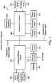
- FIG. 1is an exemplary block diagram of a system in accordance with the present disclosure
- FIG. 2is an exemplary flow diagram of the system in accordance with the present disclosure
- FIG. 3is an exemplary block diagram of a system identifying an operational status of processes and elements within a device based on the battery mode in accordance with the present disclosure.
- FIG. 4is an exemplary flow diagram of the system in accordance with the present disclosure.
- the elements shown in the figuresmay be implemented in various forms of hardware, software or combinations thereof. These elements are implemented in a combination of hardware and software on one or more appropriately programmed general-purpose devices, which may include a processor, memory and input/output interfaces.
- general-purpose deviceswhich may include a processor, memory and input/output interfaces.
- the phrase “coupled”is defined to mean directly connected to or indirectly connected with through one or more intermediate components. Such intermediate components may include both hardware and software-based components.
- processoror “controller” should not be construed to refer exclusively to hardware capable of executing software, and may implicitly include, without limitation, digital signal processor (“DSP”) hardware, read only memory (“ROM”) for storing software, random access memory (“RAM”), and nonvolatile storage.
- DSPdigital signal processor
- ROMread only memory
- RAMrandom access memory
- any switches shown in the figuresare conceptual only. Their function may be carried out through the operation of program logic, through dedicated logic, through the interaction of program control and dedicated logic, or even manually, the particular technique being selectable by the implementer as more specifically understood from the context.
- any element expressed as a means for performing a specified functionis intended to encompass any way of performing that function including, for example, a) a combination of circuit elements that performs that function or b) software in any form, including, therefore, firmware, microcode or the like, combined with appropriate circuitry for executing that software to perform the function.
- the disclosure as defined by such claimsresides in the fact that the functionalities provided by the various recited means are combined and brought together in the manner which the claims call for. It is thus regarded that any means that can provide those functionalities are equivalent to those shown herein.
- the present descriptionprovides a method and apparatus for safe and effective monitoring of battery temperature and cooling of the battery upon sensing of an over-temperature event.
- a sensormonitors the temperature of a battery and notifies a processor within the device when the over-temperature event is sensed. The processor will then disable certain heat producing resources of the device. Upon detecting the battery temperature falling below a safe temperature, the processor will conduct an orderly restoration of the disabled resources.
- the present disclosurethrottles back the devices resources upon measuring a temperature above certain trip temperatures but instead of simply re-enabling the resources in the reverse order they were disabled as the device cools, a cooled temperature below the trip temperatures is set so that when the battery cools below the cooled temperature, the device restarts/reboots itself to restore full functionality.
- the hysteresisis that the “cool down” temperature is lower than the over-temperature temperature to prevent the device from thrashing between modes.
- the deviceis restarted/rebooted to allow all devices and services to be restored in an orderly fashion.
- FIG. 1illustrates a block diagram of an exemplary device 100 incorporating the present arrangement.
- This processcan be used in any device that uses a battery such as a Lithium ion battery, such as for example phones, laptops, etc.
- the exemplary device 100includes a communications circuit 102 such as a Long-Term Evolution (LTE) module.
- a battery 106is connected to a charger integrated circuit (IC) 104 and the charger IC 104 is connected between the communications module 102 and a battery 106 , providing power for operation of the communications circuit 102 .
- LTELong-Term Evolution
- the batteryis generally seated within a battery compartment connected to the charger IC 104 .
- a battery sensor 108is connected between the charger IC 104 and the communications module 102 .
- the battery sensor 108senses the temperature of the battery, i.e. the external surface temperature of the battery and/or the heat radiated by the battery into the battery compartment, and, notifies the communications module 102 when the sensed temperature reaches a first trip temperature.
- the communications module 102is also connected to a main processor 110 for the device 100 .
- the main processor 110is connected to control other device components 112 .
- the other device componentsmay include a 5.0 GHz Wi-Fi, a 2.4 GHz Wi-Fi, a Zigbee® Radio, a Bluetooth® radio, a Z-Wave® radio, an Ethernet interface, etc.
- the above listing of other device componentsis exemplary and not exhaustive of possible components which may be connected to and controlled by the main processor 110 .
- a storage device 114may be connected to the communications module 102 for storing data such as a system history log identifying when the battery temperature reaches certain temperature levels.
- the communications module 102When the communications module 102 is notified by the battery sensor 108 that the sensed temperature has reached a certain level, the communications module 102 signals the main processor 110 to disable or re-enable certain of the device components 112 or possibly reboot the device to re-enable the disabled components in an orderly fashion.
- FIG. 2is a flow diagram showing the process of the device 100 shown in FIG. 1 .
- the processbegins with normal operation of the device.
- the battery sensor of the devicebegins monitoring the battery temperature as described in S 210 .
- the temperature sensed by the battery sensor 108is generally the external surface temperature of the battery and/or the heat radiated by the battery into the battery compartment. It is determined whether the sensed temperature exceeds a first trip temperature as stated in S 220 .
- a first trip temperature for a normal device receiving power from a Lithium Ion batterymay be 56° C. although any temperature above a normal or safe operating temperature for a device and the particular battery used thereby may be used as the first trip temperature.
- a control signalis provided by the temperature sensor to the communications module as discussed in S 230 .
- the communications modulesignals the main processor to shut down heat producing resource(s) and/or components as described in S 240 .
- the main processormay shut down resources or components producing a greatest amount of heat first in an orderly fashion and continues with resources producing less heat based on the sensed temperature. For example, when shutting down the heat producing resources or components the main processor may shut down a Wi-Fi radio, e.g. 5.0 GHz radio, producing an amount of heat greater than other components of the device first and reduce a processing speed of the main processor. The main processor may then log the over-temperature event in a system history log within the storage and enable display of notifications indicating the over-temperature event on the device.
- a Wi-Fi radioe.g. 5.0 GHz radio
- the logging of the over-temperature eventmay include at least any of a sensed temperature and a time the sensed temperature increased above the first trip temperature.
- Display of notificationsmay be at least any of displaying a message on an OLED and Web User Interface (UI) (if active), flash an LED in a “Call to action” pattern, and send a “warning” alert message to a smart phone (if paired with the device).
- UIOLED and Web User Interface
- notificationsare provided for example only and notifications by the device may be in any manner able to produce a noticeable alert of the over-temperature event indicating that the sensed temperature has reached a certain level and heat producing resources or components are being shut-down so the device will produce less heat and thereby reduce the temperature to a safe level preventing damage, overheating or failure of the battery and/or the device. While in this mode, the battery sensor continues to monitor the battery temperature.
- the battery sensorchecks to determine if the battery temperature drops to a second trip temperature lower than the first trip temperature as stated in S 250 .
- a second trip temperature for a normal device receiving power form a Lithium Ion batterymay be 54° C. although any temperature below the first trip temperature for the device and the particular battery used may be used as the second trip temperature. If the battery sensor determines that the battery temperature has dropped below the second trip temperature, the main processor is controlled to re-enable the disabled heat producing resource(s) or component(s) as discussed in S 260 .
- the second trip temperature being lower than the first trip temperatureadds hysteresis to the system preventing the system from thrashing between modes.
- the main processormay:
- the battery sensordetermines if the temperature has continued to rise above a third trip temperature as described in S 270 .
- the third trip temperatureis greater than the first trip temperature.
- the third trip temperature for a normal device receiving power form a Lithium Ion batterymay be 58° C. although any temperature above a normal operating temperature for a device and the particular battery used thereby may be used as the third trip temperature. If it is determined the battery temperature has not risen to the third trip temperature, the process returns to S 250 and continues to check if the battery temperature has decreased below the second trip temperature. If it is determined that the battery temperature has risen above the third trip temperature, the device may be placed in a “low-energy” state as stated at S 280 .
- the deviceIn a low energy state, the device should maintain certain essential resources in operation and disable other non-essential resources. For example, if able, the device should avow an attached communication device such as a phone to make calls as needed, e.g. to 911 for emergencies.
- placement of the device in the low energy statemay include:
- the deviceWhile in this mode, the device continues to monitor the battery temperature. It is then determined whether the battery temperature drops below the second trip temperature as discussed in S 290 . If it is determined that the battery temperature has not dropped below the second trip temperature, the device remains in the “low-energy” state and continues to monitor the battery temperature at S 290 . If it is determined that the battery temperature has dropped below the second trip temperature, the device begins a soft reboot, re-enabling the resources and components of the device in an orderly fashion as described in S 295 .
- the main processormay:
- the host mainboardmay be rebooted to restore full device functionality.
- the communications modulemay not be rebooted, allowing any on-going phone calls or communications to remain active.
- FIG. 3illustrates a block diagram showing the status of resources and components for a smart home gateway system for controlling appliances and devices within a smart home after determining the battery temperature has risen above the third trip temperature.
- An exemplary smart home gateway systemis the Technicolor smart home system which includes smart home (Internet of Things—IoT) features.
- In-home sensorssuch as door, window and flood sensors
- actuatorssuch as door locks and light bulbs
- smart home radiose.g. Z-Wave®, Bluetooth® and Zigbee®.
- the smart home configurationmay be communicated to a cloud-based component through an LTE radio.
- the Technicolor smart home systemcan also be paired with a smart device, e.g. Android® tablet or smartphone, Apple® iPhone, etc.
- the Technicolor smart home systemcan communicate smart home status information through the cloud to the smart device, and the smart device can be used to control the smart home sensors and actuators within the home.
- this cloud interfaceis leveraged to allow the Technicolor smart home system to communicate thermal over-temperature and cooled-down events to the smart device.
- the Technicolor smart home gateway systemis described for purposes of example. In practice any smart home system or other similar device may be used with and/or include the present disclosure. This process can also be used in any device that uses a Lithium ion battery, like phones, laptops, etc.
- the gateway system 300includes a radio 310 , a battery 320 and a charger circuit 330 connecting the radio module 310 to the battery 320 .
- the battery 320is generally seated within a battery compartment connected to the charger circuit 330 .
- a battery sensor 315is connected between the charger circuit 330 and the radio 310 .
- the battery sensor 315senses the temperature of the battery 320 , i.e. the external surface temperature of the battery 320 and/or the heat radiated by the battery 320 into the battery compartment, and, notifies the radio 310 when the sensed temperature reaches a first trip temperature.
- An OLED display 340 and a telephone interface 350may also be connected to the radio module 310 .
- the OLED display 340may communicate device/system status and other information such as over-temperature status and cooled status of the device.
- a mainboard processor 360may be connected to the radio 310 .
- the mainboard processor 360may connect to and control a 5.0 GHz Wi-Fi radio 370 and a 2.4 GHz WiFi radio 380 .
- Other radiossuch as a Z-Wave® radio 390 , a Bluetooth® radio 400 and a Zigbee® radio 410 may also be connected to the mainboard processor 360 .
- An Ethernet interface 420may also be connected to the mainboard processor 360 .
- additional components controlled by the mainboard processor 360may also be connected to the mainboard processor 360 .
- the gateway system 300may enter a “low-energy” state.
- the radio module 310controls the mainboard processor 360 to disable certain resources.
- the mainboard processor 360may disable the 5.0 GHz Wi-Fi radio 370 ; 2.4 GHz WiFi radio 380 ; Z-Wave® radio 390 ; Bluetooth® radio 400 ; Zigbee® radio 410 ; and Ethernet interface 420 in an orderly fashion.
- the radio module 310maintains the battery 320 and charger circuit 330 in an active state.
- the telephone interface 350may also be maintained in an active state so the gateway system 300 is able to make emergency calls if necessary.
- the telephone interfaceis shown for purposes of example and in practice may be any interface through which a call or connection may be made.
- the OLED display 340may also remain active to provide a notification as to the state of gateway system 300 .
- the battery sensor 315When in the “low-energy” state, the battery sensor 315 continues to monitor the battery temperature to determine when the temperature has fallen to a certain “cooled” temperature. Upon determining the battery temperature has fallen below the “cooled” or second trip temperature, the radio module 310 may begin a soft reboot of the mainboard processor 360 re-enabling the resources connected thereto in an orderly fashion.
- FIG. 4is a flow chart illustrating the method 500 performed by the system to monitor the battery temperature and act to protect the device from failure due to overheating of the battery.
- step S 510the system is in a normal operation state and the temperature of the battery is monitored.
- the systemshuts down or disables the highest heat producing resource(s), logs the event noting the reaching of the first trip temperature and provides notifications that the battery temperature has reached the first trip temperature and the highest heat producing resource(s) has been shut down in step S 520 .
- the systemcontinues to monitor the battery temperature in step S 530 . If it is determined that the temperature drops below a cooled temperature, the disabled resources are re-enabled, the cooling event is logged and notifications indicating the cooling of the battery temperature and re-enabling of resources is provided in step S 540 . The system then returns to step S 510 to continue monitoring the temperature of the battery. If it is determined that the temperature rises above the first trip temperature to a second trip temperature, all possible resources except those supporting the ability to make calls or communicate may be shut down, the main processor speed may be throttled, the rising of the battery temperature above the second trip temperature may be logged and notifications of the temperature rising to the second trip temperature may be provided in step S 550 . The maintaining of the resources able to make phone calls in an active state enables the placing of emergency calls if necessary thus providing safety for users of the system.
- the systemcontinues to monitor the battery temperature to determine when the temperature falls below the cooled temperature in step S 560 . Once it is determined the battery temperature has dropped below the cooled temperature, the cooling event may be logged, notifications regarding the dropping of the temperature may be provided and a soft reboot/restart of the device may be initiated while maintaining operation of all maintained resources preventing the interruption of any on-going calls or communications in step S 570 . The system then returns to step S 510 to continue monitoring the temperature of the battery.
Landscapes
- Engineering & Computer Science (AREA)
- Theoretical Computer Science (AREA)
- Physics & Mathematics (AREA)
- General Engineering & Computer Science (AREA)
- General Physics & Mathematics (AREA)
- Software Systems (AREA)
- Human Computer Interaction (AREA)
- Computer Security & Cryptography (AREA)
- Charge And Discharge Circuits For Batteries Or The Like (AREA)
- Power Sources (AREA)
Abstract
Description
- a. Re-enable the disabled resources such as a 5.0 GHz Wi-Fi radio;
- b. Log the “cooled” event in the system history log;
- c. Remove the notifications such as from the device OLED and Web UI, and stop the “Call to action” flashing pattern on the LED; and/or
- d. Send a “cooled” alert to a paired smart phone or device.
The battery sensor may then return to normal operation continuing to sense the battery temperature at S210.
- a. Shutting down non-essential resources and components such as, in a gateway device for example, local smart home functionality (rules engine) and “smart home” radios (2.4 GHz Wi-Fi, Z-Wave® radio, Bluetooth® radio, Zigbee® radio);
- b. Throttle back the main processor speed;
- c. Log the higher over-temperature event in the system history log; and
- d. enable display of notifications on the device. Display of notification may be at least any of display a message on an OLED and/or Web User interface (UI) (if active), flash an LED in a “Call to action” pattern, and send an “overheated” alert message to a smart phone (if paired with the device). These notifications are provided for example only and notifications by the device may be in any manner able to provide an alert that the sensed battery temperature has reached a certain level and the device is being placed in a “low-energy” state to reduce the battery temperature to a safe level, minimizing or preventing damage, overheating or failure.
Claims (21)
Priority Applications (1)
| Application Number | Priority Date | Filing Date | Title |
|---|---|---|---|
| US15/996,402US11493967B2 (en) | 2018-06-01 | 2018-06-01 | Thermal shutdown with hysteresis |
Applications Claiming Priority (1)
| Application Number | Priority Date | Filing Date | Title |
|---|---|---|---|
| US15/996,402US11493967B2 (en) | 2018-06-01 | 2018-06-01 | Thermal shutdown with hysteresis |
Publications (2)
| Publication Number | Publication Date |
|---|---|
| US20190369683A1 US20190369683A1 (en) | 2019-12-05 |
| US11493967B2true US11493967B2 (en) | 2022-11-08 |
Family
ID=68692622
Family Applications (1)
| Application Number | Title | Priority Date | Filing Date |
|---|---|---|---|
| US15/996,402ActiveUS11493967B2 (en) | 2018-06-01 | 2018-06-01 | Thermal shutdown with hysteresis |
Country Status (1)
| Country | Link |
|---|---|
| US (1) | US11493967B2 (en) |
Cited By (1)
| Publication number | Priority date | Publication date | Assignee | Title |
|---|---|---|---|---|
| US20220272514A1 (en)* | 2021-02-19 | 2022-08-25 | Samsung Electronics Co., Ltd. | Electronic device and operating method |
Families Citing this family (9)
| Publication number | Priority date | Publication date | Assignee | Title |
|---|---|---|---|---|
| JP7044692B2 (en)* | 2018-12-20 | 2022-03-30 | 本田技研工業株式会社 | Shooting system for mobile objects |
| US10936456B1 (en)* | 2019-02-20 | 2021-03-02 | Apple Inc. | Handling malfunction in a memory system comprising a nonvolatile memory by monitoring bad-block patterns |
| US11226671B2 (en)* | 2019-02-27 | 2022-01-18 | Micron Technology, Inc. | Power translator component |
| US11740944B2 (en)* | 2019-12-12 | 2023-08-29 | Advanced Micro Devices, Inc. | Method and apparatus for managing processor functionality |
| CN113885623A (en)* | 2021-10-28 | 2022-01-04 | 西安热工研究院有限公司 | A kind of internal environment intelligent control system applied to photovoltaic greenhouse |
| US12432244B2 (en)* | 2022-03-24 | 2025-09-30 | At&T Intellectual Property I, L.P. | Home gateway monitoring for vulnerable home internet of things devices |
| CN114816548B (en)* | 2022-05-25 | 2024-06-25 | 四川华旭智研科技有限公司 | Method for remotely starting electronic equipment at low temperature |
| US12399846B2 (en) | 2022-12-27 | 2025-08-26 | Advanced Micro Devices, Inc. | Physical adjustment to system memory with chipset attached memory |
| CN118693393A (en)* | 2023-03-24 | 2024-09-24 | 本田技研工业株式会社 | Controls |
Citations (37)
| Publication number | Priority date | Publication date | Assignee | Title |
|---|---|---|---|---|
| US4827288A (en)* | 1983-08-22 | 1989-05-02 | Ricoh Company, Ltd. | Pattern memory for use in thermal recording |
| US5796280A (en)* | 1996-02-05 | 1998-08-18 | Cherry Semiconductor Corporation | Thermal limit circuit with built-in hysteresis |
| US20030065459A1 (en)* | 2001-02-23 | 2003-04-03 | Power Measurement, Ltd. | Expandable intelligent electronic device |
| US20030160715A1 (en)* | 1999-06-24 | 2003-08-28 | Shigenobu Maeda | Semiconductor device, method of manufacturing semiconductor device and communication method |
| US6745138B2 (en)* | 2001-02-23 | 2004-06-01 | Power Measurement, Ltd. | Intelligent electronic device with assured data storage on powerdown |
| US20060043937A1 (en)* | 2004-08-31 | 2006-03-02 | Joseph Patino | Method and system for obtaining ambient temperatures |
| US20060098371A1 (en)* | 2004-11-08 | 2006-05-11 | Wambsganss Peter M | Temperature sensor for power supply |
| US7084378B2 (en)* | 2004-02-26 | 2006-08-01 | Mack Trucks, Inc. | Mass-flow sensor heating element protection method and apparatus |
| US20060282826A1 (en)* | 2005-06-09 | 2006-12-14 | Dockser Kenneth A | Microprocessor with automatic selection of SIMD parallelism |
| US20070052461A1 (en)* | 2005-08-16 | 2007-03-08 | Monolithic Power Systems, Inc. | Linear charger where the material temperature directly affects the circuit thermal control |
| US7202789B1 (en)* | 2003-02-03 | 2007-04-10 | Ingrid, Inc. | Clip for RFID transponder of a security network |
| US20070235440A1 (en)* | 2006-04-05 | 2007-10-11 | Youfan Gu | Multiple heater control system with expandable modular functionality |
| US20080042621A1 (en)* | 2006-07-04 | 2008-02-21 | Campagnolo S.R.L. | Method for Controlling and System for Charging a Battery Power Supply Unit |
| US20090040259A1 (en)* | 2007-08-06 | 2009-02-12 | Samsung Electronics Co., Ltd. | Inkjet image forming apparatus |
| US20090164153A1 (en) | 2007-12-25 | 2009-06-25 | Canon Kabushiki Kaisha | Apparatus using a battery |
| US7607828B2 (en) | 2006-09-22 | 2009-10-27 | Infineon Technologies Ag | Methods and systems for protection from over-stress |
| US7961446B2 (en)* | 2005-09-16 | 2011-06-14 | Rohm Co., Ltd. | Temperature protection circuit, power supply, and electronic device |
| WO2012100049A1 (en) | 2011-01-19 | 2012-07-26 | E. I. Du Pont De Nemours And Company | Lithium battery separator with shutdown function |
| US8453000B2 (en)* | 2010-08-31 | 2013-05-28 | Infinidat Ltd. | Method and system for reducing power consumption in an emergency shut-down situation |
| US8853518B2 (en)* | 2011-09-09 | 2014-10-07 | Eaton Corporation | System employing a thermoelectric device to power an electronic circuit from heat generated by semiconductor devices, and method of powering a system |
| US8970562B2 (en)* | 2005-03-01 | 2015-03-03 | Apple Inc. | LCD module with thermal sensor integrated and its implementation |
| US8993136B2 (en)* | 2011-06-30 | 2015-03-31 | Lg Chem, Ltd. | Heating system for a battery module and method of heating the battery module |
| US9005120B2 (en)* | 2008-02-29 | 2015-04-14 | Richard H. Ryan | Vital signs monitoring using personal protective equipment |
| CN204290410U (en) | 2014-12-15 | 2015-04-22 | 深圳声物互动科技有限公司 | One fills formula portable power source soon |
| CN105554412A (en) | 2016-02-15 | 2016-05-04 | 广东欧珀移动通信有限公司 | A camera method, device and mobile terminal based on screen fill light |
| US9423152B2 (en)* | 2013-03-15 | 2016-08-23 | R. J. Reynolds Tobacco Company | Heating control arrangement for an electronic smoking article and associated system and method |
| US20160261202A1 (en)* | 2015-03-05 | 2016-09-08 | Rohm Co., Ltd. | Isolated dc/dc converter, feedback circuit thereof, power supply device, power supply adaptor, and electronic device using the same |
| US20160360785A1 (en)* | 2015-06-09 | 2016-12-15 | R.J. Reynolds Tobacco Company | Electronic smoking article including a heating apparatus implementing a solid aerosol generating source, and associated apparatus and method |
| US9592543B2 (en)* | 2006-12-05 | 2017-03-14 | Elkins Earthworks, Llc | Portable gas monitor |
| US9604631B2 (en)* | 2014-01-09 | 2017-03-28 | Zhejiang Geely Automotive Reseach Institute Co. Ltd. | Hybrid vehicle and air-conditioning system thereof |
| US9711670B2 (en)* | 2012-08-21 | 2017-07-18 | Fluxphoton Corporation | Self-charging electronic devices |
| US9735613B2 (en)* | 2012-11-19 | 2017-08-15 | Heat Assured Systems, Llc | System and methods for controlling a supply of electric energy |
| US9996068B2 (en)* | 2015-02-05 | 2018-06-12 | Ramasamy Lakshmanan | Intelligent wireless and wired control of devices |
| US20190082114A1 (en)* | 2017-09-11 | 2019-03-14 | Samsung Electronics Co., Ltd. | Apparatus and method for processing image received through a plurality of cameras |
| US20190166536A1 (en)* | 2017-11-24 | 2019-05-30 | Samsung Electronics Co., Ltd. | Electronic device and communication method thereof |
| US20200192443A1 (en)* | 2018-12-14 | 2020-06-18 | Samsung Electronics Co., Ltd. | Systems and methods for temperature control management in mobile devices |
| US20200205662A1 (en)* | 2017-09-15 | 2020-07-02 | Amotech Co., Ltd. | Body temperature sensor module to be attached to skin, comprising intelligent semiconductor |
- 2018
- 2018-06-01USUS15/996,402patent/US11493967B2/enactiveActive
Patent Citations (44)
| Publication number | Priority date | Publication date | Assignee | Title |
|---|---|---|---|---|
| US4827288A (en)* | 1983-08-22 | 1989-05-02 | Ricoh Company, Ltd. | Pattern memory for use in thermal recording |
| US5796280A (en)* | 1996-02-05 | 1998-08-18 | Cherry Semiconductor Corporation | Thermal limit circuit with built-in hysteresis |
| US20030160715A1 (en)* | 1999-06-24 | 2003-08-28 | Shigenobu Maeda | Semiconductor device, method of manufacturing semiconductor device and communication method |
| US7191076B2 (en)* | 2001-02-23 | 2007-03-13 | Power Measurement Ltd. | Expandable intelligent electronic device |
| US20030065459A1 (en)* | 2001-02-23 | 2003-04-03 | Power Measurement, Ltd. | Expandable intelligent electronic device |
| US6745138B2 (en)* | 2001-02-23 | 2004-06-01 | Power Measurement, Ltd. | Intelligent electronic device with assured data storage on powerdown |
| US7202789B1 (en)* | 2003-02-03 | 2007-04-10 | Ingrid, Inc. | Clip for RFID transponder of a security network |
| US7084378B2 (en)* | 2004-02-26 | 2006-08-01 | Mack Trucks, Inc. | Mass-flow sensor heating element protection method and apparatus |
| US20060043937A1 (en)* | 2004-08-31 | 2006-03-02 | Joseph Patino | Method and system for obtaining ambient temperatures |
| US20060098371A1 (en)* | 2004-11-08 | 2006-05-11 | Wambsganss Peter M | Temperature sensor for power supply |
| US7408132B2 (en)* | 2004-11-08 | 2008-08-05 | Rrc Power Solutions Gmbh | Temperature sensor for power supply |
| US8970562B2 (en)* | 2005-03-01 | 2015-03-03 | Apple Inc. | LCD module with thermal sensor integrated and its implementation |
| US20060282826A1 (en)* | 2005-06-09 | 2006-12-14 | Dockser Kenneth A | Microprocessor with automatic selection of SIMD parallelism |
| US20070052461A1 (en)* | 2005-08-16 | 2007-03-08 | Monolithic Power Systems, Inc. | Linear charger where the material temperature directly affects the circuit thermal control |
| US7961446B2 (en)* | 2005-09-16 | 2011-06-14 | Rohm Co., Ltd. | Temperature protection circuit, power supply, and electronic device |
| US20070235440A1 (en)* | 2006-04-05 | 2007-10-11 | Youfan Gu | Multiple heater control system with expandable modular functionality |
| US20080042621A1 (en)* | 2006-07-04 | 2008-02-21 | Campagnolo S.R.L. | Method for Controlling and System for Charging a Battery Power Supply Unit |
| US9469202B2 (en)* | 2006-07-04 | 2016-10-18 | Campagnolo S.R.L. | Method for controlling and system for charging a battery power supply unit |
| US7607828B2 (en) | 2006-09-22 | 2009-10-27 | Infineon Technologies Ag | Methods and systems for protection from over-stress |
| US9592543B2 (en)* | 2006-12-05 | 2017-03-14 | Elkins Earthworks, Llc | Portable gas monitor |
| US20090040259A1 (en)* | 2007-08-06 | 2009-02-12 | Samsung Electronics Co., Ltd. | Inkjet image forming apparatus |
| US20090164153A1 (en) | 2007-12-25 | 2009-06-25 | Canon Kabushiki Kaisha | Apparatus using a battery |
| US9005120B2 (en)* | 2008-02-29 | 2015-04-14 | Richard H. Ryan | Vital signs monitoring using personal protective equipment |
| US8453000B2 (en)* | 2010-08-31 | 2013-05-28 | Infinidat Ltd. | Method and system for reducing power consumption in an emergency shut-down situation |
| US20130022858A1 (en) | 2011-01-19 | 2013-01-24 | E.I. Du Pont De Nemours And Company | Lithium battery separator with shutdown function |
| US20130017431A1 (en) | 2011-01-19 | 2013-01-17 | E. I. Du Pont De Nemours And Company | Lithium battery separator with shutdown function |
| WO2012100064A1 (en) | 2011-01-19 | 2012-07-26 | E. I. Du Pont De Nemours And Company | Lithium battery separator with shutdown function |
| WO2012100049A1 (en) | 2011-01-19 | 2012-07-26 | E. I. Du Pont De Nemours And Company | Lithium battery separator with shutdown function |
| US8993136B2 (en)* | 2011-06-30 | 2015-03-31 | Lg Chem, Ltd. | Heating system for a battery module and method of heating the battery module |
| US8853518B2 (en)* | 2011-09-09 | 2014-10-07 | Eaton Corporation | System employing a thermoelectric device to power an electronic circuit from heat generated by semiconductor devices, and method of powering a system |
| US9711670B2 (en)* | 2012-08-21 | 2017-07-18 | Fluxphoton Corporation | Self-charging electronic devices |
| US9735613B2 (en)* | 2012-11-19 | 2017-08-15 | Heat Assured Systems, Llc | System and methods for controlling a supply of electric energy |
| US9423152B2 (en)* | 2013-03-15 | 2016-08-23 | R. J. Reynolds Tobacco Company | Heating control arrangement for an electronic smoking article and associated system and method |
| US9604631B2 (en)* | 2014-01-09 | 2017-03-28 | Zhejiang Geely Automotive Reseach Institute Co. Ltd. | Hybrid vehicle and air-conditioning system thereof |
| CN204290410U (en) | 2014-12-15 | 2015-04-22 | 深圳声物互动科技有限公司 | One fills formula portable power source soon |
| US9996068B2 (en)* | 2015-02-05 | 2018-06-12 | Ramasamy Lakshmanan | Intelligent wireless and wired control of devices |
| US20160261202A1 (en)* | 2015-03-05 | 2016-09-08 | Rohm Co., Ltd. | Isolated dc/dc converter, feedback circuit thereof, power supply device, power supply adaptor, and electronic device using the same |
| US20160360785A1 (en)* | 2015-06-09 | 2016-12-15 | R.J. Reynolds Tobacco Company | Electronic smoking article including a heating apparatus implementing a solid aerosol generating source, and associated apparatus and method |
| US10226073B2 (en)* | 2015-06-09 | 2019-03-12 | Rai Strategic Holdings, Inc. | Electronic smoking article including a heating apparatus implementing a solid aerosol generating source, and associated apparatus and method |
| CN105554412A (en) | 2016-02-15 | 2016-05-04 | 广东欧珀移动通信有限公司 | A camera method, device and mobile terminal based on screen fill light |
| US20190082114A1 (en)* | 2017-09-11 | 2019-03-14 | Samsung Electronics Co., Ltd. | Apparatus and method for processing image received through a plurality of cameras |
| US20200205662A1 (en)* | 2017-09-15 | 2020-07-02 | Amotech Co., Ltd. | Body temperature sensor module to be attached to skin, comprising intelligent semiconductor |
| US20190166536A1 (en)* | 2017-11-24 | 2019-05-30 | Samsung Electronics Co., Ltd. | Electronic device and communication method thereof |
| US20200192443A1 (en)* | 2018-12-14 | 2020-06-18 | Samsung Electronics Co., Ltd. | Systems and methods for temperature control management in mobile devices |
Non-Patent Citations (2)
| Title |
|---|
| English Translation of CN105554412, entitled "Photographing method and device on screen light compensation and mobile terminal". |
| English Translation of CN204290410, entitled "One fills formula power source soon". |
Cited By (2)
| Publication number | Priority date | Publication date | Assignee | Title |
|---|---|---|---|---|
| US20220272514A1 (en)* | 2021-02-19 | 2022-08-25 | Samsung Electronics Co., Ltd. | Electronic device and operating method |
| US12167312B2 (en)* | 2021-02-19 | 2024-12-10 | Samsung Electronics Co., Ltd. | Electronic device and operating method |
Also Published As
| Publication number | Publication date |
|---|---|
| US20190369683A1 (en) | 2019-12-05 |
Similar Documents
| Publication | Publication Date | Title |
|---|---|---|
| US11493967B2 (en) | Thermal shutdown with hysteresis | |
| KR102379479B1 (en) | A method and an electronic device for determination of battery condition based on the pressure | |
| US9952645B2 (en) | Firmware update and power system thereof | |
| EP2990906B9 (en) | Function controlling method and electronic device supporting the same | |
| TWI515549B (en) | Method for providing over-temperature protection of a target device, apparatus for providing over-temperature protection, and information processing system thereof | |
| EP2919345B1 (en) | Thermal protection circuit | |
| CN102789246B (en) | Thermal protection method, device and equipment with thermal protection function | |
| KR101492586B1 (en) | Booting a mobile electronic device with a low battery based on a dynamic boot threshold | |
| CN106371540B (en) | System power management method, chip and electronic equipment | |
| CN110210260B (en) | Data self-destruction system and method | |
| US10230895B2 (en) | System and method for management of battery power | |
| JP2018506946A (en) | Shut down energy panel equipment | |
| US20160282929A1 (en) | Technologies for managing power of an embedded controller during a low-power state | |
| WO2017206301A1 (en) | Information notification method and device | |
| WO2017201827A1 (en) | Charging control method and apparatus for terminal device, and terminal device | |
| JP2015507786A (en) | Adaptive temperature throttling with user configuration features | |
| CN105573372B (en) | A kind of control method and device of intelligent terminal | |
| WO2014176980A1 (en) | Charging method, device and electronic device | |
| KR101282137B1 (en) | Portable device and method of controlling thereof | |
| CN107863589B (en) | Battery processing method and device | |
| KR20190137302A (en) | Thermal shutdown with hysteresis | |
| CN112003346A (en) | Charging method and electronic device | |
| CN105094266B (en) | Battery protection system and battery protection method | |
| CN116755960A (en) | Server operation management method, device, server, electronic equipment and media | |
| BR102018011225B1 (en) | THERMAL SHUTDOWN WITH HYSTERESIS |
Legal Events
| Date | Code | Title | Description |
|---|---|---|---|
| FEPP | Fee payment procedure | Free format text:ENTITY STATUS SET TO UNDISCOUNTED (ORIGINAL EVENT CODE: BIG.); ENTITY STATUS OF PATENT OWNER: LARGE ENTITY | |
| STPP | Information on status: patent application and granting procedure in general | Free format text:NON FINAL ACTION MAILED | |
| STPP | Information on status: patent application and granting procedure in general | Free format text:FINAL REJECTION MAILED | |
| STPP | Information on status: patent application and granting procedure in general | Free format text:RESPONSE AFTER FINAL ACTION FORWARDED TO EXAMINER | |
| STPP | Information on status: patent application and granting procedure in general | Free format text:DOCKETED NEW CASE - READY FOR EXAMINATION | |
| AS | Assignment | Owner name:INTERDIGITAL CE PATENT HOLDINGS, FRANCE Free format text:ASSIGNMENT OF ASSIGNORS INTEREST;ASSIGNORS:CHRISTIAN, MICHAEL RAY;VISHNUBHATLA, SUBBU;CWICK, JOSEPH CHARLES;SIGNING DATES FROM 20200211 TO 20200716;REEL/FRAME:053275/0391 | |
| STPP | Information on status: patent application and granting procedure in general | Free format text:PUBLICATIONS -- ISSUE FEE PAYMENT VERIFIED | |
| STCB | Information on status: application discontinuation | Free format text:ABANDONED -- FAILURE TO PAY ISSUE FEE | |
| STPP | Information on status: patent application and granting procedure in general | Free format text:DOCKETED NEW CASE - READY FOR EXAMINATION | |
| STPP | Information on status: patent application and granting procedure in general | Free format text:NOTICE OF ALLOWANCE MAILED -- APPLICATION RECEIVED IN OFFICE OF PUBLICATIONS | |
| AS | Assignment | Owner name:INTERDIGITAL MADISON PATENT HOLDINGS, SAS, FRANCE Free format text:ASSIGNMENT OF ASSIGNORS INTEREST;ASSIGNOR:INTERDIGITAL CE PATENT HOLDINGS, SAS;REEL/FRAME:059921/0030 Effective date:20210926 | |
| STPP | Information on status: patent application and granting procedure in general | Free format text:DOCKETED NEW CASE - READY FOR EXAMINATION | |
| STPP | Information on status: patent application and granting procedure in general | Free format text:NOTICE OF ALLOWANCE MAILED -- APPLICATION RECEIVED IN OFFICE OF PUBLICATIONS | |
| STPP | Information on status: patent application and granting procedure in general | Free format text:PUBLICATIONS -- ISSUE FEE PAYMENT VERIFIED | |
| STCF | Information on status: patent grant | Free format text:PATENTED CASE |