US11493601B2 - High density LIDAR scanning - Google Patents
High density LIDAR scanningDownload PDFInfo
- Publication number
- US11493601B2 US11493601B2US16/209,697US201816209697AUS11493601B2US 11493601 B2US11493601 B2US 11493601B2US 201816209697 AUS201816209697 AUS 201816209697AUS 11493601 B2US11493601 B2US 11493601B2
- Authority
- US
- United States
- Prior art keywords
- light
- light pulses
- power
- scanning
- light source
- Prior art date
- Legal status (The legal status is an assumption and is not a legal conclusion. Google has not performed a legal analysis and makes no representation as to the accuracy of the status listed.)
- Active, expires
Links
- 230000003287optical effectEffects0.000claimsabstractdescription29
- 238000005286illuminationMethods0.000claimsabstractdescription6
- 230000010355oscillationEffects0.000claimsdescription10
- 238000001514detection methodMethods0.000claimsdescription7
- 230000010287polarizationEffects0.000claimsdescription6
- 239000000835fiberSubstances0.000claimsdescription4
- 230000004044responseEffects0.000claimsdescription2
- 239000007787solidSubstances0.000claimsdescription2
- 238000000034methodMethods0.000abstractdescription9
- 239000003990capacitorSubstances0.000description12
- 238000010586diagramMethods0.000description7
- 230000008878couplingEffects0.000description6
- 238000010168coupling processMethods0.000description6
- 238000005859coupling reactionMethods0.000description6
- 230000008569processEffects0.000description3
- 238000013459approachMethods0.000description2
- 238000013461designMethods0.000description2
- 230000006870functionEffects0.000description2
- 238000012544monitoring processMethods0.000description2
- 241001465754MetazoaSpecies0.000description1
- 230000002776aggregationEffects0.000description1
- 238000004220aggregationMethods0.000description1
- 230000003321amplificationEffects0.000description1
- 239000011521glassSubstances0.000description1
- 238000002329infrared spectrumMethods0.000description1
- 230000010354integrationEffects0.000description1
- 230000007246mechanismEffects0.000description1
- 238000012986modificationMethods0.000description1
- 230000004048modificationEffects0.000description1
- 238000003199nucleic acid amplification methodMethods0.000description1
- 238000005070samplingMethods0.000description1
- 239000012780transparent materialSubstances0.000description1
- 238000002211ultraviolet spectrumMethods0.000description1
- 238000001429visible spectrumMethods0.000description1
Images


Classifications
- G—PHYSICS
- G01—MEASURING; TESTING
- G01S—RADIO DIRECTION-FINDING; RADIO NAVIGATION; DETERMINING DISTANCE OR VELOCITY BY USE OF RADIO WAVES; LOCATING OR PRESENCE-DETECTING BY USE OF THE REFLECTION OR RERADIATION OF RADIO WAVES; ANALOGOUS ARRANGEMENTS USING OTHER WAVES
- G01S7/00—Details of systems according to groups G01S13/00, G01S15/00, G01S17/00
- G01S7/48—Details of systems according to groups G01S13/00, G01S15/00, G01S17/00 of systems according to group G01S17/00
- G01S7/481—Constructional features, e.g. arrangements of optical elements
- G01S7/4811—Constructional features, e.g. arrangements of optical elements common to transmitter and receiver
- G—PHYSICS
- G01—MEASURING; TESTING
- G01S—RADIO DIRECTION-FINDING; RADIO NAVIGATION; DETERMINING DISTANCE OR VELOCITY BY USE OF RADIO WAVES; LOCATING OR PRESENCE-DETECTING BY USE OF THE REFLECTION OR RERADIATION OF RADIO WAVES; ANALOGOUS ARRANGEMENTS USING OTHER WAVES
- G01S17/00—Systems using the reflection or reradiation of electromagnetic waves other than radio waves, e.g. lidar systems
- G01S17/87—Combinations of systems using electromagnetic waves other than radio waves
- G—PHYSICS
- G01—MEASURING; TESTING
- G01S—RADIO DIRECTION-FINDING; RADIO NAVIGATION; DETERMINING DISTANCE OR VELOCITY BY USE OF RADIO WAVES; LOCATING OR PRESENCE-DETECTING BY USE OF THE REFLECTION OR RERADIATION OF RADIO WAVES; ANALOGOUS ARRANGEMENTS USING OTHER WAVES
- G01S17/00—Systems using the reflection or reradiation of electromagnetic waves other than radio waves, e.g. lidar systems
- G01S17/88—Lidar systems specially adapted for specific applications
- G01S17/89—Lidar systems specially adapted for specific applications for mapping or imaging
- G01S17/894—3D imaging with simultaneous measurement of time-of-flight at a 2D array of receiver pixels, e.g. time-of-flight cameras or flash lidar
- G—PHYSICS
- G01—MEASURING; TESTING
- G01S—RADIO DIRECTION-FINDING; RADIO NAVIGATION; DETERMINING DISTANCE OR VELOCITY BY USE OF RADIO WAVES; LOCATING OR PRESENCE-DETECTING BY USE OF THE REFLECTION OR RERADIATION OF RADIO WAVES; ANALOGOUS ARRANGEMENTS USING OTHER WAVES
- G01S17/00—Systems using the reflection or reradiation of electromagnetic waves other than radio waves, e.g. lidar systems
- G01S17/88—Lidar systems specially adapted for specific applications
- G01S17/93—Lidar systems specially adapted for specific applications for anti-collision purposes
- G01S17/931—Lidar systems specially adapted for specific applications for anti-collision purposes of land vehicles
- G—PHYSICS
- G01—MEASURING; TESTING
- G01S—RADIO DIRECTION-FINDING; RADIO NAVIGATION; DETERMINING DISTANCE OR VELOCITY BY USE OF RADIO WAVES; LOCATING OR PRESENCE-DETECTING BY USE OF THE REFLECTION OR RERADIATION OF RADIO WAVES; ANALOGOUS ARRANGEMENTS USING OTHER WAVES
- G01S7/00—Details of systems according to groups G01S13/00, G01S15/00, G01S17/00
- G01S7/48—Details of systems according to groups G01S13/00, G01S15/00, G01S17/00 of systems according to group G01S17/00
- G01S7/481—Constructional features, e.g. arrangements of optical elements
- G01S7/4817—Constructional features, e.g. arrangements of optical elements relating to scanning
- G—PHYSICS
- G01—MEASURING; TESTING
- G01S—RADIO DIRECTION-FINDING; RADIO NAVIGATION; DETERMINING DISTANCE OR VELOCITY BY USE OF RADIO WAVES; LOCATING OR PRESENCE-DETECTING BY USE OF THE REFLECTION OR RERADIATION OF RADIO WAVES; ANALOGOUS ARRANGEMENTS USING OTHER WAVES
- G01S7/00—Details of systems according to groups G01S13/00, G01S15/00, G01S17/00
- G01S7/48—Details of systems according to groups G01S13/00, G01S15/00, G01S17/00 of systems according to group G01S17/00
- G01S7/483—Details of pulse systems
- G01S7/486—Receivers
- G01S7/4861—Circuits for detection, sampling, integration or read-out
- G01S7/4863—Detector arrays, e.g. charge-transfer gates
- G—PHYSICS
- G01—MEASURING; TESTING
- G01S—RADIO DIRECTION-FINDING; RADIO NAVIGATION; DETERMINING DISTANCE OR VELOCITY BY USE OF RADIO WAVES; LOCATING OR PRESENCE-DETECTING BY USE OF THE REFLECTION OR RERADIATION OF RADIO WAVES; ANALOGOUS ARRANGEMENTS USING OTHER WAVES
- G01S7/00—Details of systems according to groups G01S13/00, G01S15/00, G01S17/00
- G01S7/48—Details of systems according to groups G01S13/00, G01S15/00, G01S17/00 of systems according to group G01S17/00
- G01S7/483—Details of pulse systems
- G01S7/486—Receivers
- G01S7/4865—Time delay measurement, e.g. time-of-flight measurement, time of arrival measurement or determining the exact position of a peak
- G—PHYSICS
- G02—OPTICS
- G02B—OPTICAL ELEMENTS, SYSTEMS OR APPARATUS
- G02B26/00—Optical devices or arrangements for the control of light using movable or deformable optical elements
- G02B26/08—Optical devices or arrangements for the control of light using movable or deformable optical elements for controlling the direction of light
- G02B26/10—Scanning systems
- G02B26/101—Scanning systems with both horizontal and vertical deflecting means, e.g. raster or XY scanners
- G—PHYSICS
- G02—OPTICS
- G02B—OPTICAL ELEMENTS, SYSTEMS OR APPARATUS
- G02B26/00—Optical devices or arrangements for the control of light using movable or deformable optical elements
- G02B26/08—Optical devices or arrangements for the control of light using movable or deformable optical elements for controlling the direction of light
- G02B26/10—Scanning systems
- G02B26/12—Scanning systems using multifaceted mirrors
- G02B26/123—Multibeam scanners, e.g. using multiple light sources or beam splitters
Definitions
- the present disclosuregenerally relates to light detection and ranging (LiDAR) systems and, more specifically, to systems for providing high density LiDAR scanning of objects in a field-of-view.
- LiDARlight detection and ranging
- a LiDAR systemtransmits light pulses to illuminate objects in a field-of-view and collect returning light pulses. Based on the returning light pulses, the LiDAR system calculates the time-of-flight and in turn determines the distance of a particular object. Typically, not all returning light pulses are collected by a LiDAR system due to the limited aperture for collecting the returning light pulses.
- a light detection and ranging (LiDAR) scanning systemincludes a light source configured to generate one or more light beams; and a beam steering apparatus optically coupled to the light source.
- the beam steering apparatusincludes a first rotatable mirror and a second rotatable mirror.
- An axis that is perpendicular to a reflective surface of the first rotatable mirroris configured to be at a first angle to a first rotating axis of the first rotatable mirror
- an axis that is perpendicular to a reflective surface of the second rotatable mirroris configured to be at a second angle to a second rotating axis of the second rotatable mirror.
- At least one of the first angle or the second angleis greater than zero degree and less than 90 degree.
- the first rotatable mirror and the second rotatable mirrorwhen moving with respect to each other, are configured to: steer the one or more light beams both vertically and horizontally to illuminate an object within a field-of-view; redirect one or more returning light pulses generated based on the illumination of the object; and a receiving optical system configured to receive the redirected returning light pulses.
- a scanning systemthat is disposed with a vehicle.
- the systemincludes a first light detection and ranging (LiDAR) scanning system disposed approximately at a front-left corner of the vehicle; a second LiDAR scanning system disposed approximately at a front-right corner of the vehicle; and a third LiDAR scanning system disposed approximately at a top portion of a front window-shield of the vehicle.
- LiDARlight detection and ranging
- a light detection and ranging (LiDAR) scanning systemincludes a light source configured to generate one or more light beams; and a beam steering apparatus optically coupled to the light source.
- the beam steering apparatusincludes a first mirror and a rotatable mirror.
- the first mirroris an oscillation mirror or a Galvo mirror.
- An axis that is perpendicular to a reflective surface of the first mirroris configured to be at a first angle to an oscillation axis of the first mirror, and an axis that is perpendicular to a reflective surface of the rotatable mirror is configured to be at a second angle to a second rotating axis of the second rotatable mirror.
- At least one of the first angle or the second angleis greater than zero degree and less than 90 degree.
- the first mirror and the rotatable mirrorwhen moving with respect to each other, are configured to: steer the one or more light beams both vertically and horizontally to illuminate an object within a field-of-view; redirect one or more returning light pulses generated based on the illumination of the object; and a receiving optical system configured to receive the redirected returning light pulses.
- FIG. 1illustrates an exemplary LiDAR scanning system that includes a beam steering apparatus having two rotatable mirrors.
- FIG. 2Aillustrates a diagram of exemplary scanning results of an exemplary LiDAR system that includes a beam steering apparatus having two rotatable mirrors.
- FIG. 2Billustrates a diagram of a single frame of the exemplary scanning results of an exemplary LiDAR system that includes a beam steering apparatus having two rotatable mirrors.
- FIG. 2Cillustrates an exemplary LiDAR scanning system that includes a light source that transmits light beams at an angle based on scanning range requirements.
- FIGS. 3A-3Cillustrates an exemplary configurations of a light source.
- FIG. 4Aillustrates exemplary scanning results of an exemplary LiDAR scanning system that includes a light source having multiple light emitting devices.
- FIG. 4Billustrates a single frame of the exemplary scanning results of an exemplary LiDAR scanning system that includes a light source having multiple light emitting devices.
- FIG. 5illustrates a circuit diagram of an exemplary driver circuit configured to provide electrical power to a light source of the LiDAR scanning system.
- FIG. 6illustrates a typical configuration of multiple LiDAR systems attached to a vehicle.
- FIG. 7illustrates an exemplary configuration of multiple LiDAR systems attached to a vehicle.
- FIG. 8illustrates an exemplary flow chart for a method of determining time of flight of one or more light pulses, according to examples of the disclosure.
- a typical LiDAR scanning systemhas limited apertures for collecting returning light pulses. Increasing the apertures are thus desired.
- the various configuration of LiDAR systems described in this applicationcan increase the aperture for collecting returning light pulses. In turn, the increased aperture improves the scanning range in both horizontal and vertical scanning directions, and therefore enables detecting more objects in the field-of-view.
- the various configuration of LiDAR systems described in this applicationcan also provide overlapping scanning results in a pre-determined scanning range (e.g., short distances from the vehicle in both horizontal and vertical directions). The overlapping scanning results obtained for the pre-determined scanning range can thus provide a high density scanning, resulting in a high-resolution image.
- various configuration of disposing multiple LiDAR systems in a vehiclecan reduce or eliminate possible scanning gaps where objects in the field-of-view may not be detected. This in turn reduces or eliminates the likelihood that a vehicle collide with the undetected objects.
- a centralized laser delivery system and multiple LiDAR systemscan be disposed in or integrated with robots, installed at multiple locations of a building for security monitoring purposes, or installed at traffic intersections or certain location of roads for traffic monitoring, etc.
- FIG. 1illustrates an exemplary LiDAR scanning system 100 that includes a beam steering apparatus having two rotatable mirrors 108 and 110 .
- LiDAR scanning system 100can be 2D or 3D scanning LiDAR system.
- LiDAR scanning system 100includes a light source 102 , an optical element 104 , a first rotatable mirror 108 , a second rotatable mirror 110 , and a receiving optical system 114 . As illustrated in FIG.
- first rotatable mirror 108 and second rotatable mirror 110when moving with respect to each other, can be configured to steer one or more light beams 107 both vertically and horizontally to illuminate one or more objects within the field-of-view of LiDAR scanning system 100 , and redirect one or more returning light pulses generated based on the illumination of the objects.
- Light source 102can generate one or more light beams 107 that include incident light pulses.
- Light source 102can be a laser light source such as a fiber laser, a diode laser, a diode pump solid state laser, and/or a fiber coupled diode laser.
- the laser light generated by light source 102can have a wavelength in the visible spectrum.
- the laser lightcan have a wavelength in the infrared spectrum.
- the laser lightcan have a wavelength in the ultra violet spectrum.
- one or more light beams 107 that include incident light pulsesare transmitted toward first rotatable mirror 108 via an optical element 104 .
- optical element 104can include a lens and/or an opening for focusing and/or directing light beams 107 to first rotatable mirror 108 .
- first rotatable mirror 108can redirect the incident light pulses of light beams 107 toward second rotatable mirror 110 .
- first rotatable mirror 108can generate redirected light pulses 109 based on incident light pulses of light beams 107 .
- First rotatable mirror 108can be configured to rotate about a first rotating axis 108 B at a speed of, for example, 199 r/s (revolutions per second).
- first rotating axis 108 Bis not, or does not overlap with, the axis that is perpendicular to a reflective surface (e.g., surface 108 S) of the first rotatable mirror 108 (e.g., the nominal axis 108 A of first rotatable mirror 108 ).
- first rotating axis 108 Bcan be configured to be at a first angle 108 C with axis 108 A, which is the axis that is perpendicular to reflective surface 108 S of the first rotatable mirror 108 .
- first angle 108 Ais an angle that is greater than 0 degrees and less than 90 degrees.
- first angle 108 Acan be 10 degrees.
- configuring first rotating mirror 108 to rotate about first rotating axis 108 B that is not the mirror's nominal axiscan scan the transmitting/redirecting light pulses to the objects at different horizontal and vertical angles in the field of view, and for receiving and redirecting the corresponding returning light pulses (e.g., light pulses 112 B).
- first rotatable mirror 108can be configured to redirect incident light pulses of one or more light beams 107 toward second rotatable mirror 110 .
- first rotatable mirror 108 Bbased on the incident light pulses of light beams 107 , first rotatable mirror 108 B generates redirected light pulses 109 .
- Redirected light pulses 109are received by second rotatable mirror 110 .
- second rotatable mirror 110can be configured to rotate about a second rotating axis 110 B.
- second rotatable mirror 110can be configured to rotate at a speed that is different from the rotation speed of the first rotatable mirror 108 .
- the first rotatable mirror 108can rotate at 199 r/s and the second rotatable mirror 110 can rotate at 189 r/s.
- second rotating axis 110 Bis not, or does not overlap with, the axis that is perpendicular to a reflective surface (e.g., surface 1105 ) of the second rotatable mirror 110 (e.g., the nominal axis 110 A of second rotatable mirror 110 ).
- second rotating axis 110 Bcan be configured to be at a second angle 110 C with axis 110 A, which is the axis that is perpendicular to a reflective surface 1105 of the second rotatable mirror 110 .
- second angle 110 Cis an angle that is greater than 0 degrees and less than 90 degrees.
- second angle 110 Ccan be 8 degrees.
- Second angle 110 Ccan be the same or different from first angle 108 C (e.g., first angle 108 C is 10 degrees, and second angle 110 C is 8 degrees).
- configuring the second rotating mirror 110 to rotate about second rotating axis 110 B that is not the nominal axiscan scan the transmitting/redirecting light pulses to the objects at different horizontal and vertical angles in the Field of View (“FOV”), and for receiving and redirecting the corresponding returning light pulses (e.g., light pulses 112 A).
- FOVField of View
- both first angle 108 C and second angle 110 Ccan be different from 90 degrees (e.g., greater than 0 degree and less than 90 degree). That is, both first rotatable mirror 108 and second rotatable mirror 110 are rotated at an angle with respect to their respective nominal axes (e.g., axes 108 A and 110 A). Configuring the mirrors in this manner can scan the transmitting/redirecting light pulses to the objects at different horizontal and vertical angles in the field of view and thus increase the scanning range and density of LiDAR scanning system 100 .
- second rotatable mirror 110receives redirected light pulses 109 from first rotatable mirror 108 , and generates and transmits steered light pulses 111 in both the horizontal and vertical directions to illuminate objects in the FOV. It is appreciated that the direction of steered light pulses 111 shown in FIG. 1 only illustrates the direction at a particular point of time. In other points in time, steered light pulses 111 can be transmitted in other directions to illuminate objects in the FOV.
- first rotatable mirror 108 and second rotatable mirror 110can be near 100% reflective mirrors that are disposed along the optical path for collecting returning light pulses 112 A (and redirected returning light pulses 112 B-C).
- one or more steered light pulses 111illuminate one or more objects in the FOV and are reflected or scattered. Some of the reflected or scattered light pulses return to second rotatable mirror 110 as returning light pulses 112 A.
- Second rotatable mirror 110redirects returning light pulses 112 A to generate redirected returning light pulses 112 B in a substantially reverse direction of redirected light pulses 109 .
- second rotatable mirror 110can be configured to rotate about second rotating axis 110 B that is at second angle 110 C (e.g., an 8-degree angle) to the mirror's nominal axis 110 A.
- first rotatable mirror 108redirects redirected returning light pulses 112 B to generate second redirected returning light pulses 112 C.
- first rotatable mirror 108can be configured to rotate about first rotating axis 108 B that is at first angle 108 C (e.g., a 10-degree angle) to the mirror's nominal axis 108 A.
- first rotatable mirror 108can be configured to direct second redirected returning light pulses 112 C toward the optical element 104 , which in turn generates third redirected returning light pulses 112 D that are collected by the receiving optical system 114 .
- Receiving optical system 114can include, for example, a converging lens 115 and a light detector 116 .
- Light detector 116can include one or more light detector elements.
- Converging lens 115is configured to collect and direct second redirected returning light pulses 112 C to light detector 116 .
- the converging lens 115can be made from any transparent material such as high index glass, plastic, or the like.
- FIG. 1illustrates an exemplary position that receiving optical system 114 may be disposed. It is appreciated that receiving optical system 114 can be disposed at any desired position to effectively collect a substantial portion of third redirected returning light pulses 112 D.
- receiving optical system 114can include a light detector 116 that includes an array of light detector elements.
- light detector 116can include an array of 16 detector elements for detecting light pulses collected by converging lens 115 .
- the number of detector elements in the arraycan be the same as or different from the number of light emitting devices (e.g., devices 302 A-D and 304 A-D described in more detail below) in light source 102 .
- the number of detector elementscan be 16 and the number of light emitting devices can be 4. The higher number of detector elements can increase the resolution of the LiDAR scanning results.
- one of the first rotatable mirror 108 and second rotatable mirror 110can be replaced with an oscillation mirror or a Galvo mirror.
- An oscillation mirrorcan oscillate about an axis at a predetermined frequency or rate. Similar to a rotatable mirror, the oscillation mirror can redirect light pulses to illuminate the objects in the FOV and collect and redirect returning light pulses to the receiving optical system and light detector.
- the oscillation frequency or rate of an oscillation mirrorcan be configured based on the scanning range requirement and/or the scanning density requirement.
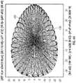
- FIG. 2Aillustrates a diagram 200 of exemplary scanning results of an exemplary LiDAR system 100 that includes a beam steering apparatus having two rotatable mirrors (e.g., mirrors 108 and 110 ).
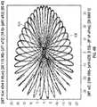
- FIG. 2Billustrates a diagram of a single frame of the exemplary scanning results shown in FIG. 2A .
- the scanning results illustrated in FIG. 2Arepresent scanning patterns 202 of multiple frames collected/integrated over a predetermined period of time (e.g., 1 second or 10 seconds); and the scanning result illustrated in FIG. 2B represents the scanning patterns 204 of a single frame (e.g., collected over 0.1 second).
- a predetermined period of timee.g. 1 second or 10 seconds
- the scanning result illustrated in FIG. 2Brepresents the scanning patterns 204 of a single frame (e.g., collected over 0.1 second).
- the horizontal axisindicates the scanning range in the horizontal scanning direction (e.g., corresponding to the x direction shown in FIG. 1 ); and the vertical axis can indicate the scanning range in the vertical scanning direction (e.g., corresponding to the y direction shown in FIG. 1 ).
- the horizontal scanning range of this particular configuration of LiDAR scanning system 100can be, for example, about ⁇ 35 degree to 35 degree; and the vertical scanning range can be, for example, about ⁇ 21 degree to 21 degree.
- the center portion 206 of the scanning patterns 202 and 204can have a higher density than other portions of the scanning patterns. The higher density of scanning is often desirable because it can provide a higher resolution LiDAR scanning.
- the higher scanning density in the center portion 206is obtained as a result of configuring both first rotatable mirror 108 and second rotatable mirror 110 to rotate about a rotating axis (e.g., 108 B and 110 B) that does not overlap or align with the nominal axis of the respective mirror.
- a rotating axise.g., 108 B and 110 B
- one or more attributes of LiDAR scanning system 100are customizable.
- one or more attributes of LiDAR scanning system 100can be configured to obtain desired scanning ranges and scanning density based on a scanning range requirement and/or a scanning density requirement.
- first rotatable mirror 108can be configured to rotate at a speed of 199 r/s;
- the first angle 108 Ce.g., the angle between the first rotating axis 108 B and nominal axis 108 A
- the second rotatable mirror 110can be configured to rotate at a speed of 189 r/s;
- the second angle 110 Ce.g., the angle between the second rotating axis 110 B and nominal axis 110 A
- the horizontal scanning rangecan be, for example, about ⁇ 35 degree to 35 degree; the vertical scanning range can be, for example, about ⁇ 21 degree to 21 degree; the high-density center portion 206 can have a horizontal scanning range of about 8 degrees and vertical scanning range of 3 degrees.
- high-density center portion 206can correspond to a scanning area in the FOV that is predetermined to have more objects or has a heightened level of detection requirement (e.g., the nearby front area of a LiDAR scanning system mounted on a vehicle).
- having horizontal scanning range that is greater than the vertical scanning rangeis often desirable.
- scanning more area across the horizontal directione.g., the x direction shown in FIG. 1 such as the direction that is parallel to the road surface
- scanning more area across the vertical directione.g., the y direction shown in FIG. 1 such as the direction that is perpendicular to the road surface.
- objectse.g., human, building, animals, etc.
- first rotatable mirror 108 and second rotatable mirror 110can be configured to be the same. In other embodiments, they can be configured to be different. For example, as illustrated in FIGS. 1, 2A and 2B , first angle 108 C (e.g., 10 degrees) can be configured to be different from second angle 110 C (e.g., 8 degrees); and the rotating speed of first rotatable mirror 108 (e.g., 199 r/s) can be configured to be different from rotating speed of second rotatable mirror 110 (e.g., 189 r/s). The rotating speed of a rotatable mirror can determine the distance between neighboring scanning lines. The rotating speed difference between the first rotatable mirror 108 and second rotatable mirror 110 can determine the rate of scanning (e.g., determine the scanning range in one second).
- first angle 108 Ce.g. 10 degrees
- second angle 110 Ce.g. 8 degrees
- the rotating speed of first rotatable mirror 108e.g.,
- light source 102can be configured to generate the one or more light beams 107 at a frequency in accordance with the scanning density requirements associated with one or more scanning directions. For example, because the scanning density is a function of the spacing between two adjacent scanning lines and the spacing is a function of the scanning frequency, the frequency of the light beams 107 can be adjusted to obtain the desired scanning density at different portion of the scanning pattern. For instance, to obtain a higher scanning density in the center portion of the FOV than in the edge portions of the FOV, the scanning frequency of light source 102 can be configured to be higher when scanning the center portion of the FOV than when scanning the edge of the FOV. Further, in some embodiments, a scanning frequency of light source 102 can also be configured to be different from the scanning frequencies of other light sources in adjacent LiDAR scanning systems to avoid interference.
- light source 102can be configured to transmit the or more light beams 107 at a direction in accordance with scanning range requirements of one or more scanning directions. For example, as shown in FIG. 1 , light source 102 can be configured to transmit light beams 107 along the z direction (e.g., no tilt with respect to the z direction). As a result shown in FIGS.
- the scanning range in the vertical directioncan be about ⁇ 21 degrees to 21 degrees (i.e., total about 42 degrees) and the scanning range in the horizontal direction (e.g., the x direction) can be about ⁇ 35 degrees to 35 degrees (i.e., total about 70 degrees).
- light source 102can be configured to transmit light beams 107 at an angle to the z direction.
- the anglecan be more than 0 degrees and less than 90 degrees.
- light source 102can be configured to transmit light beams 107 at about 30 degrees angle to the z direction (i.e., tilted with respect to the z direction).
- FIGS. 3A-3Billustrates exemplary configurations of a light source 102 .
- light source 102can include a plurality of light emitting devices. Each of the light emitting devices can generate, for example, a laser beam.
- light source 102can include a plurality of light emitting devices 302 A-D forming a rectangular-shaped array.
- light source 102can include a plurality of light emitting devices 304 A-D having a cross-shape.
- each of the light emitting devices 304 A-Dcan include a plurality of light emitting elements.
- the light detector 116as shown in FIG.
- FIGS. 4A-4Billustrate exemplary scanning results of LiDAR scanning system 100 that includes a light source 102 having multiple light emitting devices.
- using a plurality of light emitting devicescan further increase the scanning density by generating multiple scanning points or lines in the scanning results.
- the LiDAR scanning results shown in FIGS. 2A-2Bare generated by a LiDAR scanning system having a light source with a single light emitting device.
- the LiDAR scanning results shown in FIGS. 4A-4Bare generated by a LiDAR scanning system 100 having a light source with multiple (e.g., 4 ) light emitting devices (e.g., devices 304 A-D).
- 2A-2B and 4A-4Bare obtained using similar attributes of the rotatable mirrors (e.g., similar rotating speed, similar tilting angles, etc.).
- the scanning ranges of a system having multiple light emitting devices in both the horizontal and vertical directionsare similar to a system having a single light emitting device; while the scanning density of the former system is higher than the latter system in both scanning directions.
- the scanning density of the center portion 406can also be further increased to provide a higher resolution scanning result.
- each of the light emitting devicescan generate and transmit light beams independently from each other. Transmitting light beams from different light emitting devices independently allows multiple light detectors in a LiDAR scanning system to share an amplifier and analog-to-digital converter, thereby reducing the overall dimension of the LiDAR scanning system and also improving the efficiencies of the system.
- a single light emitting device in a light source 102can be configured to transmit an elongate light beam (e.g., from a diode laser), thus enabling a configuration of using one light emitting device for multiple light detectors.
- LiDAR scanning system 100can be configured to include any number of light emitting devices and any number of light detectors.
- a light source 102includes two light emitting devices 308 A and 308 B disposed at about 90 degree angle with respect to each other (e.g., as part of a cross-shaped configuration shown in FIG. 3B ).
- Light emitting device 308 Acan be configured to transmit a light beam 307 A having a horizontal polarization; and light emitting device 308 B can be configured to transmit a light beam 307 B having a vertical polarization.
- FIG. 3Ca light source 102 includes two light emitting devices 308 A and 308 B disposed at about 90 degree angle with respect to each other (e.g., as part of a cross-shaped configuration shown in FIG. 3B ).
- Light emitting device 308 Acan be configured to transmit a light beam 307 A having a horizontal polarization; and light emitting device 308 B can be configured to transmit a light beam 307 B having a vertical polarization.
- a polarization-sensitive device 309can be disposed in the optical path of both light beams 307 A and 307 B.
- the polarization-sensitive device 309allows horizontally-polarized light (parallel to the paper surface) to pass through; and reflects the vertically-polarized light (perpendicular to the paper surface) to a substantially 90 degree direction. Accordingly, light beams 307 A and 307 B can both be directed to a same direction.
- FIG. 5illustrates a circuit diagram of an exemplary driver circuit 500 configured to provide electrical power to a light source of a LiDAR scanning system (e.g., system 100 ).
- driver circuit 500can include an electrical power source 502 , a current limiting device 504 , a power controller 512 , and a power delivery circuit 552 .
- Driver circuit 500is electrically coupled to light source 102 .
- light source 102can include, for example, a light emitting device that generates light beams (e.g., a 905 nm laser beam).
- electrical power source 502can be a voltage source and/or a current source. Electrical power source 502 can be coupled to power controller 512 using an electrical wire and optionally current limiting device 504 .
- Current limiting device 504limits the electrical current to protect the components of driver circuit 500 from electrical overstress.
- Current limiting device 504can be, for example, an inductor and/or a resistor.
- power controller 512is configured to control a level of the electrical power to-be-delivered to light source 102 .
- power controller 512includes a voltage divider circuit configured to generate a plurality of discrete voltage levels.
- an exemplary voltage divider circuitinclude a plurality of capacitors C 1 -C 4 coupled in a serial manner. For example, a first terminal of capacitor C 1 is electrically coupled to the current limiting device 504 ; a second terminal of capacitor C 1 is electrically coupled to a first terminal of capacitor C 2 ; a second terminal of capacitor C 2 is electrically coupled to a first terminal of capacitor C 3 ; and so forth.
- the second terminal of capacitor C 4is electrically coupled to an electrical ground.
- the voltage divider as shown in FIG. 5can provide an output voltage that is a fraction of its input voltage. For example, for a DC input voltage applied at coupling point 514 D, the voltage divider can generate a plurality of discrete voltage levels at each coupling point 514 A-C. Each of the discrete voltage levels can be a different fraction of the voltage at coupling point 514 D depending on the capacitance of capacitors C 1 -C 4 .
- capacitors C 1 -C 4can be configured in any desirable manner (e.g., the same or different), and the voltage divider circuit of power controller 512 can include any number of capacitors, resistors, inductors, or a combination of these electrical components.
- capacitors C 1 -C 4can be replaced with resistors R 1 -R 4 .
- power controller 512can further include a plurality of switches configured to enable selection of the plurality of discrete voltage levels at coupling point 514 A- 514 D.
- power controller 512includes switch S 1 -S 4 that are controllable by a plurality of control signals PWR_SEL 1 to PWR_SEL 4 , respectively. For example, if the control signal PWR_SEL 4 is enabled and other control signals are disabled, switch S 4 can be closed and the voltage at coupling point 514 A can be selected and coupled to power delivery circuit 552 .
- control signal PWR_SEL 3if the control signal PWR_SEL 3 is enabled and other control signals are disabled, switch S 3 can be closed and the voltage at coupling point 514 B can be selected and coupled to power delivery circuit 552 ; and so forth. It is appreciated that the number of control signals can be configured corresponding to the number of discrete voltage levels in the voltage divider.
- the power controller 512can be configured to control the level of the electrical power to-be-delivered to the light source 102 for each light pulse.
- the power selection signal PWR_SEL 4can be enabled to close switch S 4 for a first light pulse
- the power selection signal PWR_SEL 3can be enabled to close switch S 3 for a second light pulse.
- different light pulsescan have different power levels.
- the controlling of power levels for light pulsescan be based on the objects in the FOV.
- the power levels of light pulsescan be adjusted according to the distance and geometry of the objects in the FOV. The power levels can also be adjusted based on the prior received optical power at the light detector.
- the adjusting of the power levelscan be part of a feedback and/or feedforward control loop. If the prior received optical power is determined to be low, insufficient, or otherwise undesirable (e.g., the power level of the detected returning light pulses is low, which may indicate an object is located far away from the LiDAR scanning system or that the object is absorbing the transmitted light pulses at a high level), the power level can be increased for the next light pulse.
- power controller 512can be electrically coupled to power delivery circuit 552 .
- power delivery circuit 552includes a charge storage device 554 configured to store electrical charges corresponding to the level of the electrical power to-be-delivered to the light source 102 .
- Charge storage device 554can be, for example, a capacitor.
- Power delivery circuit 552can also include a charge releasing device 556 configured to receive a trigger signal; and in response to receiving the trigger signal, deliver the stored electrical charges to the source 102 .
- power control signals PWR_SEL 1 -PWR_SEL 4controls the voltage level at the input terminal of charge storage device 554 , which stores the charge over a period of time.
- a trigger signalcan be enabled to turn on the charge releasing device 556 .
- the trigger signalcan be configured to turn on and off the charge releasing device 556 at a pre-determined rate or frequency such that one or more light pulses are generated from light source 102 .
- FIG. 6illustrates a typical configuration of multiple LiDAR systems disposed with a vehicle 600 .
- LiDAR system 602 Ais attached to vehicle 600 at the middle front
- LiDAR system 602 Bis attached to vehicle 600 at the driver side rear-view mirror
- LiDAR system 602 Cis attached to vehicle 600 at the passenger side rear-view mirror.
- the FOV of the LIDAR systems 602 A-Cmay have gap and thus the LiDAR systems may be unable to detect some objects in the surrounding environment of vehicle 600 .
- FIG. 6illustrates a typical configuration of multiple LiDAR systems disposed with a vehicle 600 .
- LiDAR system 602 Ais attached to vehicle 600 at the middle front
- LiDAR system 602 Bis attached to vehicle 600 at the driver side rear-view mirror
- LiDAR system 602 Cis attached to vehicle 600 at the passenger side rear-view mirror.
- the FOV of the LIDAR systems 602 A-Cmay have gap and thus the LiDAR systems may be unable to detect some objects in
- the FOV of LiDAR system 602 A(indicated by the two lines extending from system 602 A) may not be wide enough to detect a vehicle 640 that is approaching an intersection. While the FOV of LiDAR system 602 B (indicated by the two lines extending from system 602 B) may be able to cover the area of vehicle 640 , the scanning light pulses from system 602 B may be obstructed, for example, by a building at the intersection, such that vehicle 640 cannot be detected. As a result, there is a gap of scanning between system 602 A and 602 B, and accident may occur at the intersection. Thus, this typical configuration of disposing the LiDAR systems in a vehicle may not meet the safety requirements.
- FIG. 7illustrates an exemplary configuration of multiple LiDAR systems attached to a vehicle 700 .
- a LiDAR scanning system 702 Acan be disposed approximately at the front-left corner of vehicle 700 ; a LiDAR scanning system 702 B can be disposed approximately at the front-right corner of vehicle 700 ; and a LiDAR scanning system 702 C can be disposed approximately at the top portion of a front window-shield of vehicle 700 .
- one or more additional LiDAR systemscan be optionally disposed at other part of vehicle 700 .
- LiDAR system 702 Dcan be disposed approximately at the top portion of a rear window of vehicle 700 .
- the FOV of LiDAR system 702 A(indicated by the two lines extending from system 702 A) can be configured to encompass a substantial portion of the left side of vehicle 700 ; the FOV of LiDAR system 702 B can be configured to encompass a substantial portion of the right side of vehicle 700 ; and the FOV of LiDAR system 702 C can be configured to encompass a substantial front portion of a front side of vehicle 700 .
- the LiDAR systems 702 A-Ccan be configured such that the FOVs of the multiple LiDAR systems 702 A-C overlap with each other and do not leave a gap.
- a vehicle 740 that approaches the intersectioncan be detected by at least one of LiDAR system 702 A or 702 C.
- LiDAR system 702 A or 702 Cthe objects in the surrounding environment of vehicle 700 can be properly detected and potential blind spot can be eliminated to reduce or eliminate the likelihood of collision.
- FIG. 8illustrates an exemplary flow chart 800 for a method of determining time of flight of one or more light pulses for generating a 3D image using a LiDAR scanning system (e.g., system 100 depicted in FIG. 1 ).
- a LiDAR scanning systeme.g., system 100 depicted in FIG. 1
- one or more light pulsese.g., short laser light pulses having a pulse width of about 0.01 nanosecond to 5 nanoseconds or light pulses having a pulse width of 5 nanoseconds to 30 nanoseconds or longer
- a beam steering apparatuscan steer or scan the one or more light pulses across the field-of-view in both horizontal and vertical directions.
- the beam steering apparatuscan include two mirrors (e.g., two rotatable mirrors, one rotatable mirror and one oscillation mirror, or one rotatable mirror and one Glavo mirror).
- a portion of the scattered or reflected light pulsescan return to the LiDAR scanning system and reach a collection aperture of the LiDAR scanning system.
- the one or more returning light pulsescan be collected and/or redirected by the beam steering apparatus toward a receiving optical system.
- the one or more redirected returning light pulsescan be received at the receiving optical system including, for example, a converging lens and one or more light detectors.
- a distance to the objectcan be determined based on the returning light pulses.
- the one or more light detectorsconvert photons of the redirected returning light pulses that reach the light detectors to one or more electrical signals.
- the one or more output electrical signals generated by the light detectorcan be amplified using an amplification circuit or device by a predetermined factor.
- the amplified one or more electrical signalscan be sampled and converted to a digital value at a predetermined sampling rate.
- the digitized signal datacan be collected within a time period of the expected maximum time-of-flight (ToF) corresponding to the farthest object in the field-of-view.
- the digitized signal datacan be analyzed to determine the ToF of one or more returning light pulses, and determine the distance from the LiDAR scanning system to the reflection or scattering points of the objects.
- a microcontrollercan generate one or more sub-frames based on aggregation of the distances to one or more objects across successive or consecutive horizontal and vertical scans.
- the microcontrollercan interlace the one or more sub-frames to form a frame with higher resolution.
- Combinations such as “at least one of A, B, or C,” “one or more of A, B, or C,” “at least one of A, B, and C,” “one or more of A, B, and C,” and “A, B, C, or any combination thereof”include any combination of A, B, and/or C, and may include multiples of A, multiples of B, or multiples of C.
- combinations such as “at least one of A, B, or C,” “one or more of A, B, or C,” “at least one of A, B, and C,” “one or more of A, B, and C,” and “A, B, C, or any combination thereof”may be A only, B only, C only, A and B, A and C, B and C, or A and B and C, where any such combinations may contain one or more member or members of A, B, or C.
Landscapes
- Engineering & Computer Science (AREA)
- Physics & Mathematics (AREA)
- General Physics & Mathematics (AREA)
- Computer Networks & Wireless Communication (AREA)
- Radar, Positioning & Navigation (AREA)
- Remote Sensing (AREA)
- Electromagnetism (AREA)
- Optics & Photonics (AREA)
- Optical Radar Systems And Details Thereof (AREA)
- Mechanical Optical Scanning Systems (AREA)
Abstract
Description
Claims (22)
Priority Applications (6)
| Application Number | Priority Date | Filing Date | Title |
|---|---|---|---|
| US16/209,697US11493601B2 (en) | 2017-12-22 | 2018-12-04 | High density LIDAR scanning |
| PCT/US2018/065455WO2019125903A2 (en) | 2017-12-22 | 2018-12-13 | High density lidar scanning |
| CN201880090039.3ACN112352168B (en) | 2017-12-22 | 2018-12-13 | High density LIDAR scanning |
| CN202411012596.7ACN119001674A (en) | 2017-12-22 | 2018-12-13 | High density LIDAR scanning |
| US17/958,308US12189058B2 (en) | 2017-12-22 | 2022-09-30 | High resolution LiDAR using high frequency pulse firing |
| US18/970,394US20250102629A1 (en) | 2017-12-22 | 2024-12-05 | High density lidar systems |
Applications Claiming Priority (2)
| Application Number | Priority Date | Filing Date | Title |
|---|---|---|---|
| US201762609722P | 2017-12-22 | 2017-12-22 | |
| US16/209,697US11493601B2 (en) | 2017-12-22 | 2018-12-04 | High density LIDAR scanning |
Related Child Applications (1)
| Application Number | Title | Priority Date | Filing Date |
|---|---|---|---|
| US17/958,308ContinuationUS12189058B2 (en) | 2017-12-22 | 2022-09-30 | High resolution LiDAR using high frequency pulse firing |
Publications (2)
| Publication Number | Publication Date |
|---|---|
| US20200026071A1 US20200026071A1 (en) | 2020-01-23 |
| US11493601B2true US11493601B2 (en) | 2022-11-08 |
Family
ID=64902532
Family Applications (3)
| Application Number | Title | Priority Date | Filing Date |
|---|---|---|---|
| US16/209,697Active2040-01-01US11493601B2 (en) | 2017-12-22 | 2018-12-04 | High density LIDAR scanning |
| US17/958,308Active2039-01-20US12189058B2 (en) | 2017-12-22 | 2022-09-30 | High resolution LiDAR using high frequency pulse firing |
| US18/970,394PendingUS20250102629A1 (en) | 2017-12-22 | 2024-12-05 | High density lidar systems |
Family Applications After (2)
| Application Number | Title | Priority Date | Filing Date |
|---|---|---|---|
| US17/958,308Active2039-01-20US12189058B2 (en) | 2017-12-22 | 2022-09-30 | High resolution LiDAR using high frequency pulse firing |
| US18/970,394PendingUS20250102629A1 (en) | 2017-12-22 | 2024-12-05 | High density lidar systems |
Country Status (3)
| Country | Link |
|---|---|
| US (3) | US11493601B2 (en) |
| CN (2) | CN119001674A (en) |
| WO (1) | WO2019125903A2 (en) |
Families Citing this family (13)
| Publication number | Priority date | Publication date | Assignee | Title |
|---|---|---|---|---|
| US10942257B2 (en) | 2016-12-31 | 2021-03-09 | Innovusion Ireland Limited | 2D scanning high precision LiDAR using combination of rotating concave mirror and beam steering devices |
| US11808888B2 (en) | 2018-02-23 | 2023-11-07 | Innovusion, Inc. | Multi-wavelength pulse steering in LiDAR systems |
| WO2019165294A1 (en) | 2018-02-23 | 2019-08-29 | Innovusion Ireland Limited | 2-dimensional steering system for lidar systems |
| EP3794395A4 (en)* | 2018-05-14 | 2021-12-29 | Lumibird Limited | Multiple mirror monostatic scanning lidar optical ranging sensor |
| CA3136636C (en)* | 2019-04-12 | 2023-05-02 | Lumibird Limited | Monostatic scanning lidar using a multi-faceted polygon mirror as one of dual redirecting elements |
| US11391842B2 (en)* | 2020-01-06 | 2022-07-19 | Luminar, Llc | Adaptive scan pattern with virtual horizon estimation |
| US20220082817A1 (en)* | 2020-09-14 | 2022-03-17 | Mirada Technologies Inc. | Optical beam scanners having multiple loop scanners therein and methods of operating same |
| US11422267B1 (en)* | 2021-02-18 | 2022-08-23 | Innovusion, Inc. | Dual shaft axial flux motor for optical scanners |
| US11614521B2 (en)* | 2021-04-21 | 2023-03-28 | Innovusion, Inc. | LiDAR scanner with pivot prism and mirror |
| WO2022233049A1 (en)* | 2021-05-07 | 2022-11-10 | 深圳市大疆创新科技有限公司 | Control method, apparatus, and computer-readable storage medium |
| CN113759342B (en)* | 2021-08-31 | 2023-10-24 | 柳州柳工叉车有限公司 | Laser radar scanning method and device, computer equipment and storage medium |
| CN115856834A (en)* | 2022-07-26 | 2023-03-28 | 深圳市速腾聚创科技有限公司 | Point cloud encryption method and device, storage medium and laser radar |
| CN117491970B (en)* | 2022-07-26 | 2025-05-20 | 深圳市速腾聚创科技有限公司 | Laser radar detection method and detection device |
Citations (288)
| Publication number | Priority date | Publication date | Assignee | Title |
|---|---|---|---|---|
| US3122330A (en) | 1961-12-11 | 1964-02-25 | Ernest J Trentini | Arc reflectors |
| US3854821A (en) | 1971-10-29 | 1974-12-17 | Westinghouse Electric Corp | Optical system for wide band light energy |
| JPS5085346A (en) | 1973-11-27 | 1975-07-09 | ||
| GB2000411A (en) | 1977-06-15 | 1979-01-04 | Impulsphysik Gmbh | Ceilometric method and apparatus |
| US4412720A (en) | 1980-04-23 | 1983-11-01 | Cselt - Centro Studi E Laboratori Telecomunicazioni S.P.A. | Optical system coupling a rectangular light source to a circular light receiver |
| US4413878A (en)* | 1977-09-13 | 1983-11-08 | The Secretary Of State For Defence In Her Britannic Majesty's Government Of The United Kingdom Of Great Britain And Northern Ireland | Imaging systems |
| US4464048A (en) | 1981-03-25 | 1984-08-07 | Barr & Stroud Limited | Laser rangefinders |
| JPS63106587A (en)* | 1986-10-24 | 1988-05-11 | Hitachi Ltd | Detecting apparatus for obstacle |
| US4923263A (en)* | 1988-09-22 | 1990-05-08 | The United States Of America As Represented By The Secretary Of The Army | Rotating mirror optical scanning device |
| US5006721A (en) | 1990-03-23 | 1991-04-09 | Perceptron, Inc. | Lidar scanning system |
| JPH04223422A (en) | 1990-12-26 | 1992-08-13 | Ricoh Co Ltd | Internal polygon mirror and its manufacturing method |
| US5157451A (en) | 1991-04-01 | 1992-10-20 | John Taboada | Laser imaging and ranging system using two cameras |
| WO1992022109A1 (en) | 1991-06-07 | 1992-12-10 | Advanced Laser Technologies, Inc. | Laser beam scanning apparatus and method |
| US5206697A (en)* | 1990-10-19 | 1993-04-27 | Schwartz Electro Optics, Inc. | Tunable laser rangefinder and method |
| US5303084A (en) | 1991-08-27 | 1994-04-12 | Kaman Aerospace Corporation | Laser light beam homogenizer and imaging lidar system incorporating same |
| US5442358A (en) | 1991-08-16 | 1995-08-15 | Kaman Aerospace Corporation | Imaging lidar transmitter downlink for command guidance of underwater vehicle |
| US5510890A (en) | 1992-11-03 | 1996-04-23 | Gec-Marconi Limited | Laser radar with reference beam storage |
| US5546188A (en) | 1992-11-23 | 1996-08-13 | Schwartz Electro-Optics, Inc. | Intelligent vehicle highway system sensor and method |
| US5615004A (en)* | 1994-12-27 | 1997-03-25 | Hughes Electronics | Laser range finder power management system |
| US5657077A (en) | 1993-02-18 | 1997-08-12 | Deangelis; Douglas J. | Event recording system with digital line camera |
| US5682225A (en) | 1996-06-07 | 1997-10-28 | Loral Vought Systems Corp. | Ladar intensity image correction for laser output variations |
| US5736958A (en) | 1990-10-29 | 1998-04-07 | Essex Corporation | Image synthesis using time sequential holography |
| US5793491A (en) | 1992-12-30 | 1998-08-11 | Schwartz Electro-Optics, Inc. | Intelligent vehicle highway system multi-lane sensor and method |
| US5838239A (en) | 1992-10-20 | 1998-11-17 | Robotic Vision Systems, Inc. | System for detecting ice or snow on surface which specularly reflects light |
| US5864391A (en) | 1996-04-04 | 1999-01-26 | Denso Corporation | Radar apparatus and a vehicle safe distance control system using this radar apparatus |
| US5926259A (en) | 1995-05-04 | 1999-07-20 | Bushnell Corporation | Laser range finder with target quality display |
| US5936756A (en) | 1996-01-10 | 1999-08-10 | Ricoh Company Ltd. | Compact scanning optical system |
| US6163378A (en) | 1999-06-14 | 2000-12-19 | Khoury; Jehad | Spectroscopic time integrative correlation for rapid medical diagnostic and universal image analysis |
| US6225621B1 (en)* | 1999-05-07 | 2001-05-01 | Automatic Timing & Controls, Inc. | Laser photoelectric sensor |
| US6317202B1 (en) | 1998-11-12 | 2001-11-13 | Denso Corporation | Automotive radar detecting lane mark and frontal obstacle |
| US20010043717A1 (en) | 1998-10-23 | 2001-11-22 | Facet Technology Corporation | Method and apparatus for rapidly determining whether a digitized image frame contains an object of interest |
| EP0757257B1 (en) | 1995-07-31 | 2002-05-29 | Raytheon Company | Laser range finder receiver |
| US6420698B1 (en) | 1997-04-24 | 2002-07-16 | Cyra Technologies, Inc. | Integrated system for quickly and accurately imaging and modeling three-dimensional objects |
| EP1237305A2 (en) | 2001-02-28 | 2002-09-04 | KiloLambda IP Limited | Multi-wavelength light source |
| US20020136251A1 (en) | 2001-01-25 | 2002-09-26 | Science And Technology Corporation | Automatic gain control system for use with multiple wavelength signal detector |
| US20020149760A1 (en) | 2001-03-05 | 2002-10-17 | Sick Ag | Apparatus for determining a distance profile |
| US20020179761A1 (en) | 2001-06-04 | 2002-12-05 | Eiji Nagasaki | Tape tension controlling mechanism for magnetic recording/reproducing apparatus |
| US20030066954A1 (en) | 2001-09-03 | 2003-04-10 | Sick Ag | Optoelectronic detection device |
| US20030080285A1 (en) | 2001-10-29 | 2003-05-01 | Sick Ag | Optoelectronic distance measuring device |
| US6611318B2 (en)* | 2001-03-23 | 2003-08-26 | Automatic Timing & Controls, Inc. | Adjustable mirror for collimated beam laser sensor |
| US6650404B1 (en) | 2002-05-28 | 2003-11-18 | Analog Modules, Inc. | Laser rangefinder receiver |
| US20040135992A1 (en) | 2002-11-26 | 2004-07-15 | Munro James F. | Apparatus for high accuracy distance and velocity measurement and methods thereof |
| US6783074B1 (en) | 2002-11-07 | 2004-08-31 | Ncr Corporation | Methods and apparatus for efficient use of space in arranging and configuring optical components of bar code scanners |
| US6788445B2 (en) | 2002-01-14 | 2004-09-07 | Applied Materials, Inc. | Multi-beam polygon scanning system |
| US20050033497A1 (en) | 2003-08-06 | 2005-02-10 | Stopczynski Lawrence Gerard | Method of controlling an external object sensor for an automotive vehicle |
| US20050034036A1 (en) | 2001-06-15 | 2005-02-10 | Ulrich Lages | Method for correcting data of several opto-electronic sensors |
| US6864498B2 (en) | 2001-05-11 | 2005-03-08 | Orbotech Ltd. | Optical inspection system employing a staring array scanner |
| US20050088641A1 (en)* | 2003-10-23 | 2005-04-28 | Chih-Wei Hung | Testing method for rangefinders |
| US20050190424A1 (en) | 2004-02-27 | 2005-09-01 | Sick Ag | Method and device for optical scanning of objects |
| US20050195383A1 (en) | 1994-05-23 | 2005-09-08 | Breed David S. | Method for obtaining information about objects in a vehicular blind spot |
| CN1677050A (en) | 2004-03-31 | 2005-10-05 | 株式会社电装 | Object detector of vehicle |
| US20050218128A1 (en) | 2004-03-31 | 2005-10-06 | Han You-Hie | Laser processing apparatus with polygon mirror |
| US20060071846A1 (en) | 2003-05-30 | 2006-04-06 | Yakayuki Yanagisawa | Coherent laser radar |
| US20060132752A1 (en) | 2004-12-16 | 2006-06-22 | Kane David M | Micromechanical and related lidar apparatus and method, and fast light-routing components |
| US20060146377A1 (en) | 2003-03-07 | 2006-07-06 | Qinetiq Limited | Scanning apparatus and method |
| US20060145062A1 (en) | 2002-09-25 | 2006-07-06 | Christian Boehlau | Optoelectronic detection device |
| US20060227317A1 (en) | 2005-04-06 | 2006-10-12 | Henderson Sammy W | Efficient lidar with flexible target interrogation pattern |
| US7128267B2 (en) | 2003-07-11 | 2006-10-31 | Sick Ag | Device for optical scanning of objects, especially markings |
| US20070024840A1 (en) | 2005-07-14 | 2007-02-01 | Fetzer Gregory J | Ultraviolet, infrared, and near-infrared lidar system and method |
| US20070091948A1 (en) | 2005-07-29 | 2007-04-26 | Aculight Corporation | Multi-stage optical amplifier having photonic-crystal waveguides for generation of high-power pulsed radiation and associated method |
| CN1322307C (en) | 2004-02-27 | 2007-06-20 | 欧姆龙株式会社 | Apparatus for surface inspection and method and apparatus for inspecting substrate |
| US20070181810A1 (en) | 2006-02-06 | 2007-08-09 | Tan Michael R T | Vertical cavity surface emitting laser (VCSEL) array laser scanner |
| US20070216995A1 (en) | 2006-03-16 | 2007-09-20 | Bollond Paul G | Optical fiber laser having improved efficiency |
| US20070248136A1 (en) | 2006-04-19 | 2007-10-25 | Mobius Photonics, Inc. | Laser apparatus having multiple synchronous amplifiers tied to one master oscillator |
| JP2007301756A (en) | 2006-05-09 | 2007-11-22 | Brother Ind Ltd | Inkjet recording device |
| CN101093285A (en) | 2002-05-09 | 2007-12-26 | 精工爱普生株式会社 | Optical scanner, and mechanism for cleaning optical scanner cover glass |
| US7323987B2 (en) | 2004-06-28 | 2008-01-29 | Sigma Space Corporation | Compact single lens laser system for object/vehicle presence and speed determination |
| JP2008070159A (en) | 2006-09-12 | 2008-03-27 | Hokuyo Automatic Co | Scanning distance measuring device |
| EP1923721A1 (en) | 2005-08-15 | 2008-05-21 | Topcon Corporation | Measuring device |
| US20080174762A1 (en) | 2006-08-29 | 2008-07-24 | Jony Jiang Liu | Micro-mirror optical tracking and ranging system |
| US7405676B2 (en) | 2004-09-10 | 2008-07-29 | Gatsometer B.V. | Method and system for detecting with laser the passage by a vehicle of a point for monitoring on a road |
| CN101241182A (en) | 2007-02-06 | 2008-08-13 | 电装波动株式会社 | Laser radar apparatus for measuring direction and distance of object |
| US20080210881A1 (en) | 2005-07-29 | 2008-09-04 | Qinetiq Limited | Laser Measurement Device and Method |
| US20080247425A1 (en) | 2007-04-03 | 2008-10-09 | David Welford | Q-switched microlaser apparatus and method for use |
| US20080264164A1 (en) | 2007-04-30 | 2008-10-30 | Hunter Solheim | Autonomous continuous atmospheric present weather, nowcasting, and forecasting system |
| US20090002678A1 (en) | 2007-02-28 | 2009-01-01 | Denso Wave Incorporated | Laser radar apparatus for three-dimensional detection of objects |
| US20090010644A1 (en) | 2002-02-01 | 2009-01-08 | Cubic Corporation | Integrated optical communication and range finding system and applications thereof |
| US20090051926A1 (en) | 2007-04-13 | 2009-02-26 | United States Of America As Represented By The Administrator Of The National Aeronautics And Spac | Multiple frequency optical mixer and demultiplexer and apparatus for remote sensing |
| US20090059201A1 (en) | 2007-08-28 | 2009-03-05 | Science Applications International Corporation | Full-Field Light Detection and Ranging Imaging System |
| US20090067453A1 (en) | 2005-04-07 | 2009-03-12 | Matsushita Electric Industrial Co., Ltd. | Laser Light Source and Optical Device |
| US20090099813A1 (en) | 2007-09-20 | 2009-04-16 | Jerry Samuel Dimsdale | Time Delay Estimation |
| US20090102313A1 (en) | 2007-09-20 | 2009-04-23 | Joseph Newhall West | Transmission Lines Applied to Contact Free Slip Rings |
| US7541944B2 (en) | 2004-07-12 | 2009-06-02 | The Boeing Company | Systems and methods for collision avoidance |
| US7541943B2 (en) | 2006-05-05 | 2009-06-02 | Eis Electronic Integrated Systems Inc. | Traffic sensor incorporating a video camera and method of operating same |
| US20090147239A1 (en) | 2005-09-02 | 2009-06-11 | Neptec | Apparatus and method for tracking an object |
| US20090245302A1 (en) | 2008-03-31 | 2009-10-01 | Electro Scientific Industries, Inc. | Methods and systems for dynamically generating tailored laser pulses |
| US20090252376A1 (en) | 2000-08-12 | 2009-10-08 | Retterath Jamie E | System for Road Sign Sheeting Classification |
| US20090262760A1 (en) | 2005-01-20 | 2009-10-22 | Vladimir Krupkin | Laser Obstacle Ranging and Display |
| CN101576620A (en) | 2009-06-08 | 2009-11-11 | 北京理工大学 | Large-caliber optical periscopic non-coaxial laser radar three-dimensional scanning device |
| US20090316134A1 (en) | 2004-07-08 | 2009-12-24 | Michael Christopher E | Fiber laser ladar |
| US20090324293A1 (en) | 2008-06-27 | 2009-12-31 | Canon Kabushiki Kaisha | Image forming apparatus |
| US20100006760A1 (en) | 2004-04-13 | 2010-01-14 | Science & Engineering Services, Inc. | Ultraviolet lidar for detection of biological warfare agents |
| US20100007870A1 (en) | 2008-07-09 | 2010-01-14 | Sick Ag | Apparatus for the recognition of the presence of an object in space |
| US20100020306A1 (en) | 2006-07-13 | 2010-01-28 | Velodyne Acoustics, Inc. | High definition lidar system |
| US20100025798A1 (en) | 2006-03-27 | 2010-02-04 | Princeton Lightwave, Inc. | Apparatus Comprising a Single Photon Photodetector Having Reduced Afterpulsing and Method Therefor |
| US20100027602A1 (en) | 2008-07-31 | 2010-02-04 | United States Of America As Represented By The Administrator Of The National Aeronautics And Spac | Time delay and distance measurement |
| EP2157445A2 (en) | 2008-08-19 | 2010-02-24 | Rosemount Aerospace Inc. | Lidar system using a pseudo-random pulse sequence |
| US20100053715A1 (en) | 2006-10-30 | 2010-03-04 | O'neill James | Scanning system for lidar |
| US7679798B2 (en) | 2002-05-09 | 2010-03-16 | Seiko Epson Corporation | Optical scanning device and cover glass cleaning mechanism for optical scanning device |
| JP2010060309A (en) | 2008-09-01 | 2010-03-18 | Ihi Corp | Laser radar and method of monitoring boundary by same |
| US7697120B2 (en) | 2006-11-27 | 2010-04-13 | Riegl Laser Measurement Systems Gmbh | Scanning apparatus |
| US20100114416A1 (en) | 2008-10-30 | 2010-05-06 | Honeywell International Inc. | System and method for navigating an autonomous vehicle using laser detection and ranging |
| US20100128109A1 (en) | 2008-11-25 | 2010-05-27 | Banks Paul S | Systems And Methods Of High Resolution Three-Dimensional Imaging |
| US20100128248A1 (en) | 2008-11-21 | 2010-05-27 | Sick Ag | Optoelectronic sensor and method for the measurement of distances in accordance with light transit time principle |
| US20100165082A1 (en) | 2008-12-23 | 2010-07-01 | Sick Ag | Detection apparatus |
| US20100271614A1 (en) | 2006-01-27 | 2010-10-28 | Vijay Albuquerque | LIDAR system utilizing SOI-based opto-electronic components |
| US20100302528A1 (en) | 2009-06-02 | 2010-12-02 | Velodyne Acoustics, Inc. | Color lidar scanner |
| US7869112B2 (en) | 2008-07-25 | 2011-01-11 | Prysm, Inc. | Beam scanning based on two-dimensional polygon scanner for display and other applications |
| US20110032508A1 (en) | 2009-08-06 | 2011-02-10 | Irvine Sensors Corporation | Phase sensing and scanning time of flight LADAR using atmospheric absorption bands |
| US20110085155A1 (en) | 2009-10-08 | 2011-04-14 | Barry Lee Stann | Ladar transmitting and receiving system and method |
| US20110102764A1 (en) | 2006-09-22 | 2011-05-05 | Leica Geosystems Ag | Lidar system |
| US20110122895A1 (en) | 2009-11-23 | 2011-05-26 | Lockheed Martin Corporation | Q-switched oscillator seed-source for mopa laser illuminator method and apparatus |
| US20110181864A1 (en) | 2008-07-04 | 2011-07-28 | Eads Deutschland Gmbh | Lidar method for measuring speeds and lidar device with time-controlled detection |
| US20110216304A1 (en) | 2006-07-13 | 2011-09-08 | Velodyne Acoustics, Inc. | High definition lidar system |
| US20110235019A1 (en)* | 2010-03-23 | 2011-09-29 | Kabushiki Kaisha Toyota Chuo Kenkyusho | Light scanning apparatus and separation distance measurement apparatus |
| EP2395368A1 (en) | 2010-06-11 | 2011-12-14 | Sick AG | Distance-measuring laser scanner for detecting objects in a surveillance range |
| JP2011257193A (en) | 2010-06-07 | 2011-12-22 | Ihi Corp | Object detector |
| US20120035788A1 (en) | 2006-03-16 | 2012-02-09 | Gray & Company, Inc. | Navigation and control system for autonomous vehicles |
| US8116968B2 (en) | 2008-12-23 | 2012-02-14 | National Chiao Tung University | Method for identification of traffic lane boundary |
| KR20120013515A (en) | 2010-08-05 | 2012-02-15 | (주)이오시스템 | Avalanche Photodiode Gain Compensation Device of Optical Measuring Equipment |
| US20120038903A1 (en) | 2010-08-16 | 2012-02-16 | Ball Aerospace & Technologies Corp. | Electronically steered flash lidar |
| WO2012051700A1 (en) | 2010-10-22 | 2012-04-26 | Neptec Design Group Ltd. | Wide angle bistatic scanning optical ranging sensor |
| US20120101680A1 (en) | 2008-10-24 | 2012-04-26 | The Gray Insurance Company | Control and systems for autonomously driven vehicles |
| US20120124113A1 (en) | 2010-11-05 | 2012-05-17 | University of Maribor | LIGHT DETECTION AND RANGING (LiDAR)DATA COMPRESSION AND DECOMPRESSION METHODS AND APPARATUS |
| US20120162373A1 (en) | 2010-12-23 | 2012-06-28 | Electronics And Telecommunications Research Institute | Dynamic range three-dimensional image system |
| GB2487518A (en) | 2009-11-20 | 2012-07-25 | Faro Tech Inc | Device for optically scanning and measuring an environment |
| US8248272B2 (en) | 2005-10-31 | 2012-08-21 | Wavetronix | Detecting targets in roadway intersections |
| US20120219020A1 (en) | 1993-12-20 | 2012-08-30 | Imra America, Inc. | Environmentally stable passively modelocked fiber laser pulse source |
| US20120221142A1 (en) | 2011-02-24 | 2012-08-30 | Mss, Inc. | Sequential Scanning Of Multiple Wavelengths |
| CN102736075A (en) | 2011-03-31 | 2012-10-17 | 电装波动株式会社 | Laser radar for three-dimensional scanning |
| US8299957B2 (en) | 2010-03-19 | 2012-10-30 | Chien Cheng Technology Co., Ltd. | Method for detecting a vehicle type, a vehicle speed and width of a detecting area by a vehicle radar sensor |
| US20130050676A1 (en) | 2009-09-02 | 2013-02-28 | Trimble A.B. | Distance Measurement Methods and Apparatus |
| US20130087689A1 (en) | 2011-10-05 | 2013-04-11 | Telcordia Technologies, Inc. | System and Method for Nonlinear Optical Devices |
| US20130107016A1 (en) | 2010-05-17 | 2013-05-02 | Iee International Electronics & Engineering S.A. | Scanning 3d imager |
| US20130116971A1 (en) | 2010-06-28 | 2013-05-09 | Fraunhofer-Gesellschaft Zur Foerderung Der Angewandten Forschung E.V. | Method for generating a signal for a distance measurement and method and system for distance measurement between a transmitter and a receiver |
| KR20130068224A (en) | 2011-12-15 | 2013-06-26 | 여우순엽 | The apparatus and method of monitoring with terrestrial lidar and reflectless totalstation |
| US20130235366A1 (en) | 2012-03-07 | 2013-09-12 | Vectronix Ag | Distance measuring device |
| US20130293867A1 (en) | 2009-09-23 | 2013-11-07 | Pixart Imaging Inc. | Distance-measuring device of measuring distance according to variation of imaging location and calibrating method thereof |
| US20130293946A1 (en) | 2012-05-01 | 2013-11-07 | Imra America, Inc. | Optical frequency ruler |
| JP2013238440A (en) | 2012-05-14 | 2013-11-28 | Mitsubishi Electric Corp | Beam scan type object detector |
| US20130342822A1 (en) | 2011-03-02 | 2013-12-26 | Toyota Jidosha Kabushiki Kaisha | Laser radar device |
| US8629977B2 (en) | 2010-04-14 | 2014-01-14 | Digital Ally, Inc. | Traffic scanning LIDAR |
| US20140027607A1 (en) | 2012-05-04 | 2014-01-30 | Princeton Lightwave, Inc. | High-Repetition-Rate Single-Photon Receiver and Method Therefor |
| US8659643B2 (en) | 2011-01-18 | 2014-02-25 | Disney Enterprises, Inc. | Counting system for vehicle riders |
| US8659748B2 (en) | 2011-02-15 | 2014-02-25 | Optical Air Data Systems, Llc | Scanning non-scanning LIDAR |
| US20140063255A1 (en) | 1994-05-23 | 2014-03-06 | American Vehicular Sciences, LLC | Techniques for Improving Safe Operation of a Vehicle |
| US20140063489A1 (en) | 2012-09-06 | 2014-03-06 | Faro Technologies, Inc. | Laser Scanner |
| US20140104594A1 (en) | 2009-07-28 | 2014-04-17 | Applied Concepts, Inc. | Lidar Measurement Device with Target Tracking and Method for Use of Same |
| JP2014071038A (en) | 2012-09-28 | 2014-04-21 | Denso Wave Inc | Laser radar device |
| US20140233942A1 (en) | 2012-02-16 | 2014-08-21 | Nucrypt Llc | System and method for measuring the phase of a modulated optical signal |
| US8836955B2 (en) | 2008-09-02 | 2014-09-16 | Carl Zeiss Ag | Device and method for measuring a surface |
| US8842356B2 (en) | 2007-04-02 | 2014-09-23 | Fraunhofer-Gesellschaft Zur Foerderung Der Angewandten Forschung E.V. | Micromechanical device with temperature stabilization and method for adjusting a defined temperature or a defined temperature course on a micromechanical device |
| US20140300952A1 (en) | 2009-06-30 | 2014-10-09 | Trimble Ab | Optical pulse transmitter |
| US20140319638A1 (en) | 2011-10-20 | 2014-10-30 | Agency For Science, Technology And Research | Avalanche photodiode |
| US20140320845A1 (en) | 2011-12-23 | 2014-10-30 | Valeo Schalter Und Sensoren Gmbh | Optical measuring device and a method for producing a cover disc for a housing of an optical measuring device |
| US20140327945A1 (en) | 2004-11-15 | 2014-11-06 | Scaneva Ltd. | Method and device for scanning light |
| US20140332676A1 (en) | 2011-11-29 | 2014-11-13 | Valeo Schalter Und Sensoren Gmbh | Optical measuring device |
| US20140347650A1 (en) | 2011-12-23 | 2014-11-27 | Leica Geosystems Ag | Distance-measuring device alignment |
| US20140350836A1 (en) | 2013-05-24 | 2014-11-27 | Advance Scientific Concepts, Inc. | Automotive auxiliary ladar sensor |
| US8918270B2 (en) | 2010-10-28 | 2014-12-23 | Tongqing Wang | Wireless traffic sensor system |
| US20150015868A1 (en) | 2013-07-11 | 2015-01-15 | Sick Ag | Optoelectric Sensor and Method for the Detection and Distance Determination of Objects |
| US20150055117A1 (en) | 2013-08-20 | 2015-02-26 | Google Inc. | Devices and Methods for a Rotating LIDAR Platform with a Shared Transmit/Receive Path |
| US20150078123A1 (en) | 2013-09-16 | 2015-03-19 | Appareo Systems, Llc | Synthetic underwater visualization system |
| US20150084805A1 (en) | 2012-03-19 | 2015-03-26 | Qinetiq Limited | Detection Techniques |
| US20150109603A1 (en) | 2013-10-21 | 2015-04-23 | Electronics And Telecommunications Research Institute | Multi-wavelength image lidar sensor apparatus and signal processing method thereof |
| US20150116692A1 (en) | 2012-04-30 | 2015-04-30 | Michigan Aerospace Corporation | System and method for scan range gating |
| US20150131080A1 (en) | 2013-11-12 | 2015-05-14 | Facet Technology Corp. | Methods and Apparatus for Array Based Lidar Systems with Reduced Interference |
| US20150139259A1 (en) | 2013-11-21 | 2015-05-21 | Christie Digital Systems Canada Inc. | Method, system and apparatus for automatically determining operating conditions of a periodically poled lithium niobate crystal in a laser system |
| US20150158489A1 (en) | 2013-12-09 | 2015-06-11 | Hyundai Motor Company | Method for object processing and vehicle supporting the same |
| US20150160007A1 (en)* | 2013-12-11 | 2015-06-11 | Chongqing Aite Optical And Electronics Co., Ltd. | Laser transmitting circuit, laser receiving circuit, distance calculation circuit and devices thereof |
| EP2889642A1 (en) | 2013-12-16 | 2015-07-01 | Riegl Laser Measurement Systems GmbH | Method for distance measurement |
| US9086273B1 (en) | 2013-03-08 | 2015-07-21 | Google Inc. | Microrod compression of laser beam in combination with transmit lens |
| US20150266472A1 (en) | 2012-09-05 | 2015-09-24 | Google Inc. | Construction Zone Object Detection Using Light Detection and Ranging |
| US20150293228A1 (en) | 2014-04-11 | 2015-10-15 | Facet Technology Corp. | Methods and apparatus for object detection and identification in a multiple detector lidar array |
| US9188674B2 (en) | 2012-07-03 | 2015-11-17 | Ricoh Company, Ltd. | Laser radar device |
| US20150332102A1 (en) | 2007-11-07 | 2015-11-19 | Magna Electronics Inc. | Object detection system |
| US20150338270A1 (en) | 2012-05-10 | 2015-11-26 | Voxtel, Inc. | Discriminating photo counts and dark counts in an avalanche photodiode |
| US20150355327A1 (en) | 2012-11-21 | 2015-12-10 | Nikon Metrology Nv | Scan mirrors for laser radar |
| US20150378012A1 (en) | 2014-06-27 | 2015-12-31 | Hrl Laboratories Llc | Single chip scanning lidar and method of producing the same |
| WO2016002776A1 (en) | 2014-07-03 | 2016-01-07 | 三菱電機株式会社 | Monitoring apparatus |
| US20160003946A1 (en) | 2014-07-03 | 2016-01-07 | Advanced Scientific Concepts, Inc. | Ladar sensor for a dense environment |
| US9239959B1 (en) | 2013-04-08 | 2016-01-19 | Lockheed Martin Corporation | Multi-resolution, wide field-of-view, unmanned ground vehicle navigation sensor |
| CN105319555A (en) | 2007-02-28 | 2016-02-10 | 电装波动株式会社 | Laser radar apparatus for three-dimensional detection of target |
| US20160047900A1 (en) | 2014-08-15 | 2016-02-18 | US LADAR, Inc. | Method and System for Scanning Ladar Transmission with Pulse Modulation |
| US20160061655A1 (en) | 2014-09-03 | 2016-03-03 | Panasonic Intellectual Property Management Co., Ltd. | Measurement system |
| US20160061935A1 (en) | 2014-08-28 | 2016-03-03 | Google Inc. | Methods and Systems for Vehicle Radar Coordination and Interference Reduction |
| US9279662B2 (en) | 2012-09-14 | 2016-03-08 | Faro Technologies, Inc. | Laser scanner |
| JP2016040662A (en) | 2014-08-12 | 2016-03-24 | 株式会社Ihi | Laser radar apparatus and laser radar method |
| US20160100521A1 (en) | 2014-10-10 | 2016-04-14 | Irobot Corporation | Autonomous Robot Localization |
| US9316724B2 (en) | 2012-12-18 | 2016-04-19 | Sick Ag | Optoelectronic sensor for the detection of objects |
| US20160117048A1 (en) | 2014-09-26 | 2016-04-28 | Cypress Semiconductor Corporation | Background Light Detection for Optical Navigation Systems |
| US20160172819A1 (en) | 2014-12-12 | 2016-06-16 | Omron Corporation | Light amplifying device and laser processing apparatus |
| US20160178736A1 (en) | 2014-12-19 | 2016-06-23 | Hanwha Techwin Co., Ltd. | Lidar system |
| US20160226210A1 (en) | 2015-01-29 | 2016-08-04 | John J. Zayhowski | Systems and methods for light amplification |
| US20160245902A1 (en) | 2015-02-25 | 2016-08-25 | Abbie T. Watnik | Real-time processing and adaptable illumination lidar camera using a spatial light modulator |
| US20160291134A1 (en) | 2015-04-06 | 2016-10-06 | Google Inc. | Long Range Steerable LIDAR System |
| US9476968B2 (en) | 2014-07-24 | 2016-10-25 | Rosemount Aerospace Inc. | System and method for monitoring optical subsystem performance in cloud LIDAR systems |
| US9477007B2 (en) | 2012-10-19 | 2016-10-25 | Sick Ag | Laser scanner |
| US20160313445A1 (en) | 2012-03-16 | 2016-10-27 | Advanced Scientific Concepts, Inc. | Personal ladar sensor |
| WO2016175395A2 (en) | 2015-04-28 | 2016-11-03 | 전자부품연구원 | Multi-channel lidar scanner optical system using mirror rotation manner |
| US20160327646A1 (en) | 2015-05-07 | 2016-11-10 | GM Global Technology Operations LLC | Pseudo random sequences in array lidar systems |
| JP2017003347A (en) | 2015-06-08 | 2017-01-05 | 日本信号株式会社 | Object detection device and object detection method |
| US20170003116A1 (en) | 2015-06-30 | 2017-01-05 | Korea Research Institute Of Standards And Science | Apparatus for real-time non-contact non-destructive thickness measurement using terahertz wave |
| US20170070029A1 (en)* | 2015-09-07 | 2017-03-09 | Stmicroelectronics (Grenoble 2) Sas | Optical pulse emitter |
| US9606222B2 (en) | 2012-04-04 | 2017-03-28 | Valeo Schalter Und Sensoren Gmbh | Optoelectronic sensor device, in particular laser scanner, having an adapted receiving unit for optimized reduction of the reception level |
| US9618742B1 (en) | 2013-03-08 | 2017-04-11 | Google Inc. | Rotatable mirror assemblies |
| US9625580B2 (en) | 2014-01-03 | 2017-04-18 | Princeton Lightwave, Inc. | LiDAR system comprising a single-photon detector |
| US9680280B2 (en) | 2004-03-31 | 2017-06-13 | Imra America, Inc. | Method and apparatus for controlling and protecting pulsed high power fiber amplifier systems |
| WO2017110417A1 (en) | 2015-12-21 | 2017-06-29 | 株式会社小糸製作所 | Image acquisition device for vehicles, control device, vehicle provided with image acquisition device for vehicles and control device, and image acquisition method for vehicles |
| JP2017138301A (en) | 2016-01-28 | 2017-08-10 | 株式会社デンソー | Laser radar equipment |
| US20170242104A1 (en) | 2016-02-18 | 2017-08-24 | Aeye, Inc. | Ladar Transmitter with Induced Phase Drift for Improved Gaze on Scan Area Portions |
| US9753351B2 (en) | 2014-06-30 | 2017-09-05 | Quanergy Systems, Inc. | Planar beam forming and steering optical phased array chip and method of using same |
| US9778364B2 (en) | 2015-03-25 | 2017-10-03 | Waymo Llc | Vehicle with multiple light detection and ranging devices (LIDARs) |
| US9791555B2 (en) | 2012-04-26 | 2017-10-17 | Neptec Design Group Ltd. | High speed 360 degree scanning LIDAR head |
| US20170299721A1 (en) | 2015-11-30 | 2017-10-19 | Luminar Technologies, Inc. | Lidar system |
| US9798003B2 (en) | 2014-01-22 | 2017-10-24 | Sick Ag | Distance measuring sensor and method for the detection and distance determination of objects |
| US20170307738A1 (en) | 2013-11-22 | 2017-10-26 | Uber Technologies, Inc. | Lidar scanner calibration |
| US9817121B2 (en) | 2013-12-26 | 2017-11-14 | Kabushiki Kaisha Toyota Chuo Kenkyusho | Radar apparatus and method of determining sign of velocity |
| US9823351B2 (en) | 2012-12-18 | 2017-11-21 | Uber Technologies, Inc. | Multi-clad fiber based optical apparatus and methods for light detection and ranging sensors |
| US20170356981A1 (en)* | 2016-06-14 | 2017-12-14 | Stmicroelectronics, Inc. | Adaptive laser power and ranging limit for time of flight sensor |
| US20170365105A1 (en) | 2016-06-17 | 2017-12-21 | Ford Global Technologies, Llc | Method and apparatus for inter-vehicular safety awareness and alert |
| US9857472B2 (en) | 2013-07-02 | 2018-01-02 | Electronics And Telecommunications Research Institute | Laser radar system for obtaining a 3D image |
| US9869754B1 (en) | 2017-03-22 | 2018-01-16 | Luminar Technologies, Inc. | Scan patterns for lidar systems |
| US9869753B2 (en) | 2014-08-15 | 2018-01-16 | Quanergy Systems, Inc. | Three-dimensional-mapping two-dimensional-scanning lidar based on one-dimensional-steering optical phased arrays and method of using same |
| US9880278B2 (en) | 2013-08-01 | 2018-01-30 | Robert Bosch Gmbh | Object determination using a radar sensor |
| US20180040171A1 (en) | 2016-08-02 | 2018-02-08 | International Business Machines Corporation | Self-driving vehicle sensor fault remediation |
| US20180050704A1 (en) | 2016-08-16 | 2018-02-22 | Uber Technologies, Inc. | Autonomous vehicle diagnostic system |
| US20180152691A1 (en) | 2015-09-24 | 2018-05-31 | Ouster, Inc. | Optical system for collecting distance information within a field |
| US9989755B2 (en) | 2015-08-03 | 2018-06-05 | Sumitomo Electric Industries, Ltd. | Method of producing optical module and optical module |
| US20180156896A1 (en) | 2016-05-18 | 2018-06-07 | James Thomas O'Keeffe | Dynamically steered lidar adapted to vehicle shape |
| US20180158471A1 (en) | 2016-12-02 | 2018-06-07 | Breakaway Records, L.L.C. | Record Stabilizer for Multiple Vinyl Sizes |
| US9995820B2 (en) | 2014-05-08 | 2018-06-12 | Sick Ag | Distance-measuring sensor and method for detecting and determining the distance of objects |
| US20180188355A1 (en) | 2016-12-31 | 2018-07-05 | Innovusion Ireland Limited | 2D SCANNING HIGH PRECISION LiDAR USING COMBINATION OF ROTATING CONCAVE MIRROR AND BEAM STEERING DEVICES |
| WO2018126248A1 (en) | 2017-01-02 | 2018-07-05 | Okeeffe James | Micromirror array for feedback-based image resolution enhancement |
| US20180188357A1 (en) | 2017-01-05 | 2018-07-05 | Innovusion Ireland Limited | HIGH RESOLUTION LiDAR USING HIGH FREQUENCY PULSE FIRING |
| US20180188371A1 (en) | 2016-12-30 | 2018-07-05 | Innovusion Ireland Limited | Multiwavelength lidar design |
| US20180188358A1 (en) | 2017-01-05 | 2018-07-05 | Innovusion Ireland Limited | METHOD AND SYSTEM FOR ENCODING AND DECODING LiDAR |
| US10018724B2 (en) | 2013-02-13 | 2018-07-10 | Universitat Politecnica De Catalunya | System and method for scanning a surface and computer program implementing the method |
| WO2018129410A1 (en) | 2017-01-05 | 2018-07-12 | Innovusion Ireland Limited | Mems beam steering and fisheye receiving lens for lidar system |
| US10031214B2 (en)* | 2016-09-20 | 2018-07-24 | Innoviz Technologies Ltd | Selective illumination in LIDAR based on detection results |
| US20180210084A1 (en) | 2017-01-26 | 2018-07-26 | Sick Ag | Optoelectronic sensor and method of determining the distance of an object in a monitored zone |
| US10042159B2 (en) | 2016-02-18 | 2018-08-07 | Aeye, Inc. | Ladar transmitter with optical field splitter/inverter |
| US10048381B2 (en) | 2013-07-16 | 2018-08-14 | Valeo Schalter Und Sensoren Gmbh | Opto-electronic detection device and method for sensing the surroundings of a motor vehicle by scanning |
| US10061019B1 (en) | 2017-03-28 | 2018-08-28 | Luminar Technologies, Inc. | Diffractive optical element in a lidar system to correct for backscan |
| WO2018175990A1 (en) | 2017-03-23 | 2018-09-27 | Innovusion Ireland Limited | High resolution lidar using multi-stage multi-phase signal modulation, integration, sampling, and analysis |
| KR20180107673A (en) | 2017-03-22 | 2018-10-02 | (주) 위키옵틱스 | LIDAR light-emitting system improved pattern rotation |
| US20180284244A1 (en)* | 2017-03-28 | 2018-10-04 | Luminar Technologies, Inc. | Method for Dynamically Controlling Laser Power |
| US20180284241A1 (en) | 2017-03-29 | 2018-10-04 | Luminar Technologies, Inc. | Sizing the Field of View of a Detector to Improve Operation of a Lidar System |
| US20180284242A1 (en) | 2017-03-30 | 2018-10-04 | Luminar Technologies, Inc. | Protecting Detector in a Lidar System Using Off-Axis Illumination |
| US20180284286A1 (en) | 2017-03-31 | 2018-10-04 | Luminar Technologies, Inc. | Multi-eye lidar system |
| US10094925B1 (en) | 2017-03-31 | 2018-10-09 | Luminar Technologies, Inc. | Multispectral lidar system |
| US10107914B2 (en) | 2015-02-20 | 2018-10-23 | Apple Inc. | Actuated optical element for light beam scanning device |
| US20180329060A1 (en) | 2017-05-15 | 2018-11-15 | Ouster, Inc. | Lidar unit with an optical link between controller and photosensor layer |
| US20190011567A1 (en)* | 2017-07-05 | 2019-01-10 | Ouster, Inc. | Light ranging device with mems scanned emitter array and synchronized electronically scanned sensor array |
| US10180517B2 (en) | 2014-04-11 | 2019-01-15 | Aviation Glass & Technology Holding B.V. | Vehicle mirror, and method for manufacturing such a mirror |
| US10191155B2 (en) | 2017-03-29 | 2019-01-29 | Luminar Technologies, Inc. | Optical resolution in front of a vehicle |
| US20190094345A1 (en)* | 2017-09-25 | 2019-03-28 | Leica Geosystems Ag | Laser scanner |
| US20190107607A1 (en) | 2017-10-09 | 2019-04-11 | Luminar Technologies, Inc. | Interlaced scan patterns for lidar system |
| US20190120962A1 (en) | 2017-10-20 | 2019-04-25 | Sick Ag | Transmission/reception module for an optoelectronic sensor and method of detecting objects |
| WO2019079642A1 (en) | 2017-10-19 | 2019-04-25 | Innovusion Ireland Limited | Lidar with large dynamic range |
| US10295656B1 (en) | 2018-06-13 | 2019-05-21 | Hesai Photonics Technology Co., Ltd. | Lidar systems and methods |
| US20190154804A1 (en) | 2017-11-22 | 2019-05-23 | Luminar Technologies, Inc. | Efficient orientation of a lidar system in a vehicle |
| US20190154807A1 (en) | 2017-11-21 | 2019-05-23 | Sick Ag | Polygon scanner and method of detecting objects in a monitored zone |
| US10324170B1 (en) | 2018-04-05 | 2019-06-18 | Luminar Technologies, Inc. | Multi-beam lidar system with polygon mirror |
| US20190212416A1 (en) | 2018-01-09 | 2019-07-11 | Innovusion Ireland Limited | Lidar detection systems and methods |
| US20190257924A1 (en) | 2018-02-22 | 2019-08-22 | Innovusion Ireland Limited | Receive path for lidar system |
| US10393877B2 (en) | 2016-06-01 | 2019-08-27 | Velodyne Lidar, Inc. | Multiple pixel scanning LIDAR |
| US20190265334A1 (en) | 2018-02-23 | 2019-08-29 | Innovusion Ireland Limited | Distributed lidar systems |
| WO2019165294A1 (en) | 2018-02-23 | 2019-08-29 | Innovusion Ireland Limited | 2-dimensional steering system for lidar systems |
| US20190265337A1 (en) | 2018-02-23 | 2019-08-29 | Innovusion Ireland Limited | Multi-wavelength pulse steering in lidar systems |
| US20190277952A1 (en) | 2018-03-08 | 2019-09-12 | Zf Friedrichshafen Ag | Receiver arrangement for the reception of light impulses, lidar module and method for receiving light impulses |
| US10429495B1 (en) | 2018-04-03 | 2019-10-01 | Hesai Photonics Technology Co., Ltd. | Lidar system and method |
| US20190310368A1 (en) | 2018-04-06 | 2019-10-10 | Luminar Technologies, Inc. | Lidar System with AlInAsSb Avalanche Photodiode |
| US10451716B2 (en) | 2017-11-22 | 2019-10-22 | Luminar Technologies, Inc. | Monitoring rotation of a mirror in a lidar system |
| US10627491B2 (en) | 2017-03-31 | 2020-04-21 | Velodyne Lidar, Inc. | Integrated LIDAR illumination power control |
| US10641872B2 (en) | 2016-02-18 | 2020-05-05 | Aeye, Inc. | Ladar receiver with advanced optics |
| US20200142075A1 (en) | 2019-07-31 | 2020-05-07 | Lg Electronics Inc. | Lidar system and autonomous driving system using the same |
| US20200142074A1 (en) | 2016-03-11 | 2020-05-07 | Kaarta, Inc. | Systems and methods for improvements in scanning and mapping |
| US20200142073A1 (en) | 2018-11-02 | 2020-05-07 | Waymo Llc | Synchronization of Multiple Rotating Sensors of a Vehicle |
| US20200142076A1 (en) | 2018-11-05 | 2020-05-07 | Mapsted Corp. | Method and system for crowd-sourced trusted-gps region for mobile device localization |
| US10663564B2 (en) | 2017-03-30 | 2020-05-26 | Luminar Technologies, Inc. | Cross-talk mitigation using wavelength switching |
| US10663596B2 (en) | 2017-09-15 | 2020-05-26 | Aeye, Inc. | Ladar receiver with co-bore sited camera |
| US20200227882A1 (en) | 2018-04-09 | 2020-07-16 | Innovusion Ireland Limited | Lidar systems and methods for exercising precise control of a fiber laser |
| US10732281B2 (en) | 2017-03-28 | 2020-08-04 | Luminar Technologies, Inc. | Lidar detector system having range walk compensation |
| US20200319310A1 (en) | 2016-01-31 | 2020-10-08 | Velodyne Lidar, Inc. | Multiple pulse, lidar based 3-d imaging |
| US20200400798A1 (en) | 2019-06-21 | 2020-12-24 | Aeva, Inc. | Lidar system with solid state spectral scanning |
| US20210088630A9 (en) | 2017-04-19 | 2021-03-25 | Surestar Laser Technology (Suzhou) Co., Ltd. | Laser scanning device, radar device and scanning method thereof |
| US11002835B2 (en) | 2018-04-03 | 2021-05-11 | Hesai Photonics Technology Co., Ltd. | Distributed laser radar |
Family Cites Families (85)
| Publication number | Priority date | Publication date | Assignee | Title |
|---|---|---|---|---|
| JPS5245479B2 (en) | 1972-02-19 | 1977-11-16 | ||
| US3897150A (en) | 1972-04-03 | 1975-07-29 | Hughes Aircraft Co | Scanned laser imaging and ranging system |
| FR2251876B1 (en) | 1973-11-16 | 1977-09-23 | Thomson Brandt | |
| FR2509562A1 (en) | 1981-07-10 | 1983-01-14 | Cem Comp Electro Mec | METHOD AND APPARATUS FOR HOMOGENEOUS HEATING BY TRANSVERSE FLOW ELECTROMAGNETIC INDUCTION OF FLAT, CONDUCTOR AND AMAGNETIC PRODUCTS |
| GB2266620B (en) | 1992-04-27 | 1996-08-28 | Univ Southampton | Optical power limited amplifier |
| US5319434A (en) | 1992-12-30 | 1994-06-07 | Litton Systems, Inc. | Laser rangefinder apparatus with fiber optic interface |
| US5369861A (en) | 1994-01-21 | 1994-12-06 | Burlington Industries, Inc. | Process for recycling denim waste |
| JP3839932B2 (en) | 1996-09-26 | 2006-11-01 | キヤノン株式会社 | Process cartridge, electrophotographic image forming apparatus, electrophotographic photosensitive drum and coupling |
| US5857077A (en) | 1995-06-01 | 1999-01-05 | Fuji Xerox Co., Ltd. | Tracing system having follow-up distribution section for distributing information based on a distribution history of prior distributed information stored in distribution history storing section |
| US7312247B2 (en) | 2001-03-27 | 2007-12-25 | Errant Gene Therapeutics, Llc | Histone deacetylase inhibitors |
| US6493093B2 (en) | 2001-04-12 | 2002-12-10 | Veeco Instruments Inc. | Bat-wing attenuation in white-light interferometry |
| GB0121027D0 (en) | 2001-08-30 | 2001-10-24 | Esselte Nv | Embossing tools and tape printers |
| US20090213878A9 (en) | 2005-01-07 | 2009-08-27 | Michael Peeters | Broad-Area Microlasers and Methods for Driving Them |
| JP2007144667A (en) | 2005-11-24 | 2007-06-14 | Fuji Xerox Co Ltd | Image forming apparatus and formed image correcting method |
| US8116988B2 (en) | 2006-05-19 | 2012-02-14 | The University Of Chicago | Method for indexing nucleic acid sequences for computer based searching |
| WO2008101120A1 (en) | 2007-02-14 | 2008-08-21 | Finisar Corporation | Collimated ball lenses for optical triplexers |
| WO2009020161A1 (en) | 2007-08-07 | 2009-02-12 | Nikon Corporation | Microscope |
| SE532553C2 (en) | 2008-01-24 | 2010-02-23 | Mikael Lindstrand | Method and apparatus for obtaining high dynamic, spectral, spatial and angular resolved radius information |
| JP5172376B2 (en) | 2008-02-14 | 2013-03-27 | Hoya株式会社 | Optical device shading structure |
| US8225621B2 (en) | 2008-05-23 | 2012-07-24 | Imi Cornelius, Inc. | Detection and correction of reverse operation of a compressor in a refrigeration system |
| JP2010035385A (en) | 2008-07-31 | 2010-02-12 | Kyocera Mita Corp | Motor drive controller |
| US7880885B1 (en) | 2008-11-13 | 2011-02-01 | Lockheed Martin Corporation | Portable evaluation of window transmission |
| FR2956260B1 (en) | 2010-02-05 | 2012-04-13 | Commissariat Energie Atomique | CHARGE BALANCING SYSTEM FOR BATTERIES |
| JP5909372B2 (en) | 2012-01-19 | 2016-04-26 | 富士通コンポーネント株式会社 | Printer device and printer device control method |
| US20130241761A1 (en) | 2012-03-16 | 2013-09-19 | Nikon Corporation | Beam steering for laser radar and other uses |
| JP5915482B2 (en) | 2012-09-27 | 2016-05-11 | 豊田合成株式会社 | Intermediate assembly of airbag apparatus and assembly method of airbag apparatus |
| US9036134B2 (en)* | 2013-02-12 | 2015-05-19 | Faro Technologies, Inc. | Multi-mode optical measurement device and method of operation |
| US9183688B2 (en) | 2013-02-19 | 2015-11-10 | LaserLock Technologies Inc. | Characteristic verification system |
| MX2016003194A (en) | 2013-09-12 | 2016-06-24 | Cgg Services Sa | Ghost-suppression optimized seismic source and method. |
| US9454054B2 (en) | 2013-11-18 | 2016-09-27 | Magna Mirrors Of America, Inc. | Electro-optic mirror element and process of making same |
| JP6281942B2 (en)* | 2014-02-14 | 2018-02-21 | オムロンオートモーティブエレクトロニクス株式会社 | Laser radar apparatus and object detection method |
| DE102015213694A1 (en)* | 2015-07-21 | 2017-01-26 | Robert Bosch Gmbh | Sensor system for detecting protruding or exposed objects in the vicinity of a vehicle |
| CN204885804U (en) | 2015-07-21 | 2015-12-16 | 北京杏林睿光科技有限公司 | A narrow linewidth beam combining module and a multi-wavelength Raman laser with the module |
| CN204758260U (en) | 2015-07-21 | 2015-11-11 | 北京杏林睿光科技有限公司 | Semiconductor laser structure of multitube core characteristic monitoring |
| US10067255B2 (en) | 2015-09-04 | 2018-09-04 | Saudi Arabian Oil Company | Automatic quality control of seismic travel time |
| US9778384B1 (en) | 2016-05-24 | 2017-10-03 | Thermo Fisher Scientific Messtechnik Gmbh | Method of operational status verification for a neutron detecting device |
| JP6729210B2 (en) | 2016-09-07 | 2020-07-22 | 株式会社島津製作所 | Material testing machine |
| CN106597471B (en) | 2016-11-08 | 2019-05-24 | 上海禾赛光电科技有限公司 | Vehicle and method with transparent barriers object automatic detection function |
| CN106658366B (en) | 2016-11-30 | 2020-05-22 | 建荣半导体(深圳)有限公司 | Bluetooth working mode switching method and device, Bluetooth chip and electronic equipment |
| US10942272B2 (en) | 2016-12-13 | 2021-03-09 | Waymo Llc | Power modulation for a rotary light detection and ranging (LIDAR) device |
| WO2018128248A1 (en) | 2017-01-03 | 2018-07-12 | 엘지전자 주식회사 | Invalid unit-based image decoding method and device in image coding system for 360-degree video |
| US10007001B1 (en) | 2017-03-28 | 2018-06-26 | Luminar Technologies, Inc. | Active short-wave infrared four-dimensional camera |
| CN108132472A (en) | 2017-12-08 | 2018-06-08 | 上海禾赛光电科技有限公司 | Laser radar system |
| CN207457508U (en) | 2017-08-08 | 2018-06-05 | 上海禾赛光电科技有限公司 | Laser radar system based on two-dimensional scanning mirrors |
| CN207557465U (en) | 2017-08-08 | 2018-06-29 | 上海禾赛光电科技有限公司 | Laser radar system based on tilting mirror |
| CN109725320B (en) | 2017-10-27 | 2020-12-29 | 上海禾赛光电科技有限公司 | Laser radar |
| CN208421228U (en) | 2018-06-29 | 2019-01-22 | 上海禾赛光电科技有限公司 | laser radar system |
| CN108089201B (en) | 2017-12-08 | 2020-04-24 | 上海禾赛光电科技有限公司 | Obstacle information acquisition method, laser pulse emission method and device |
| JP2021114005A (en) | 2018-04-12 | 2021-08-05 | ソニーグループ株式会社 | Information processing device and information processing method |
| CN109116367B (en) | 2018-06-27 | 2020-05-19 | 上海禾赛光电科技有限公司 | Laser radar |
| US10466342B1 (en) | 2018-09-30 | 2019-11-05 | Hesai Photonics Technology Co., Ltd. | Adaptive coding for lidar systems |
| CN109116331B (en) | 2018-06-27 | 2020-04-24 | 上海禾赛光电科技有限公司 | Coding laser transceiver, distance measuring device and laser radar system |
| CN109116366B (en) | 2018-06-27 | 2020-05-19 | 上海禾赛光电科技有限公司 | Multi-beam laser radar with non-uniform pulse energy |
| CN208314210U (en) | 2018-06-29 | 2019-01-01 | 上海禾赛光电科技有限公司 | laser radar system |
| CN208705506U (en) | 2018-08-28 | 2019-04-05 | 上海禾赛光电科技有限公司 | A kind of lens group for laser radar |
| CN109188397B (en) | 2018-08-29 | 2020-11-24 | 上海禾赛科技股份有限公司 | Laser transmitter-receiver and laser radar |
| CN209280923U (en) | 2018-10-16 | 2019-08-20 | 上海禾赛光电科技有限公司 | It is a kind of for the receiving terminal circuit of laser radar, reception device and laser radar |
| CN112327275B (en) | 2019-01-07 | 2022-08-02 | 上海禾赛科技有限公司 | Laser radar |
| CN109814082B (en) | 2019-01-21 | 2021-10-22 | 上海禾赛科技有限公司 | Light receiving module and laser radar system |
| CN109917348B (en) | 2019-01-25 | 2020-11-03 | 上海禾赛科技股份有限公司 | Laser radar system |
| CN109917408B (en) | 2019-03-28 | 2020-04-24 | 上海禾赛光电科技有限公司 | Echo processing method and distance measuring method of laser radar and laser radar |
| EP3888203B1 (en) | 2019-04-02 | 2023-11-29 | Hesai Technology Co., Ltd. | Laser system for lidar |
| CN109950784B (en) | 2019-04-10 | 2021-05-28 | 上海禾赛科技股份有限公司 | Laser and laser radar |
| CN110988846B (en) | 2019-04-22 | 2023-07-18 | 威力登激光雷达美国有限公司 | Noise point identification method for laser radar and laser radar system |
| CN110031822B (en) | 2019-04-22 | 2020-05-22 | 上海禾赛光电科技有限公司 | Noise identification method and lidar system that can be used in lidar |
| JP7277266B2 (en) | 2019-06-05 | 2023-05-18 | キヤノン株式会社 | PWM output circuit and image forming apparatus having the same |
| CN110492856B (en) | 2019-08-12 | 2020-11-13 | 上海禾赛光电科技有限公司 | Transimpedance amplification unit circuit feedback circuit, photoelectric detection circuit and laser radar system |
| CN110492349B (en) | 2019-08-20 | 2021-03-19 | 上海禾赛科技股份有限公司 | Driving circuit, driving method and laser system |
| CN112578396B (en) | 2019-09-30 | 2022-04-19 | 上海禾赛科技有限公司 | Method and device for coordinate transformation between radars and computer-readable storage medium |
| CN110736975B (en) | 2019-11-07 | 2020-11-27 | 上海禾赛光电科技有限公司 | Receiver module and lidar including it |
| CN110784220B (en) | 2019-11-07 | 2021-02-02 | 上海禾赛光电科技有限公司 | Dynamic threshold timing circuit, laser radar and method for acquiring time information |
| CN110780283B (en) | 2019-11-22 | 2021-01-26 | 上海禾赛光电科技有限公司 | Receiving system, laser radar comprising same and echo receiving method |
| CN110780284B (en) | 2019-11-22 | 2020-12-29 | 上海禾赛光电科技有限公司 | Receiving system, laser radar including the same, and method of echo reception processing |
| CN211655309U (en) | 2019-12-23 | 2020-10-09 | 上海禾赛光电科技有限公司 | Laser and laser radar including the same |
| CN213182011U (en) | 2020-04-26 | 2021-05-11 | 上海禾赛光电科技有限公司 | Laser radar's transmitting unit, receiving element and laser radar |
| CN212623082U (en) | 2020-04-29 | 2021-02-26 | 上海禾赛光电科技有限公司 | Scanning device for laser radar and laser radar |
| EP4150378A1 (en) | 2020-05-13 | 2023-03-22 | Luminar, LLC | Lidar system with high-resolution scan pattern |
| CN213750313U (en) | 2020-11-27 | 2021-07-20 | 上海禾赛科技有限公司 | Optical window and laser radar |
| CN214151038U (en) | 2020-12-11 | 2021-09-07 | 上海禾赛科技有限公司 | Laser radar |
| CN214795206U (en) | 2021-04-07 | 2021-11-19 | 上海禾赛科技股份有限公司 | Laser radar |
| CN214795200U (en) | 2021-04-30 | 2021-11-19 | 上海禾赛科技有限公司 | Window for laser radar and laser radar |
| CN214895810U (en) | 2021-04-30 | 2021-11-26 | 上海禾赛科技有限公司 | Light splitting device and laser radar |
| CN214895784U (en) | 2021-04-30 | 2021-11-26 | 上海禾赛科技有限公司 | Optical detection device and running vehicle |
| CN215641806U (en) | 2021-04-30 | 2022-01-25 | 上海禾赛科技有限公司 | Laser radar |
| CN215932142U (en) | 2021-09-15 | 2022-03-01 | 上海禾赛科技有限公司 | Laser radar |
- 2018
- 2018-12-04USUS16/209,697patent/US11493601B2/enactiveActive
- 2018-12-13CNCN202411012596.7Apatent/CN119001674A/enactivePending
- 2018-12-13CNCN201880090039.3Apatent/CN112352168B/enactiveActive
- 2018-12-13WOPCT/US2018/065455patent/WO2019125903A2/ennot_activeCeased
- 2022
- 2022-09-30USUS17/958,308patent/US12189058B2/enactiveActive
- 2024
- 2024-12-05USUS18/970,394patent/US20250102629A1/enactivePending
Patent Citations (401)
| Publication number | Priority date | Publication date | Assignee | Title |
|---|---|---|---|---|
| US3122330A (en) | 1961-12-11 | 1964-02-25 | Ernest J Trentini | Arc reflectors |
| US3854821A (en) | 1971-10-29 | 1974-12-17 | Westinghouse Electric Corp | Optical system for wide band light energy |
| JPS5085346A (en) | 1973-11-27 | 1975-07-09 | ||
| GB2000411A (en) | 1977-06-15 | 1979-01-04 | Impulsphysik Gmbh | Ceilometric method and apparatus |
| US4413878A (en)* | 1977-09-13 | 1983-11-08 | The Secretary Of State For Defence In Her Britannic Majesty's Government Of The United Kingdom Of Great Britain And Northern Ireland | Imaging systems |
| US4412720A (en) | 1980-04-23 | 1983-11-01 | Cselt - Centro Studi E Laboratori Telecomunicazioni S.P.A. | Optical system coupling a rectangular light source to a circular light receiver |
| US4464048A (en) | 1981-03-25 | 1984-08-07 | Barr & Stroud Limited | Laser rangefinders |
| JPS63106587A (en)* | 1986-10-24 | 1988-05-11 | Hitachi Ltd | Detecting apparatus for obstacle |
| US4923263A (en)* | 1988-09-22 | 1990-05-08 | The United States Of America As Represented By The Secretary Of The Army | Rotating mirror optical scanning device |
| US5006721A (en) | 1990-03-23 | 1991-04-09 | Perceptron, Inc. | Lidar scanning system |
| US5206697A (en)* | 1990-10-19 | 1993-04-27 | Schwartz Electro Optics, Inc. | Tunable laser rangefinder and method |
| US5736958A (en) | 1990-10-29 | 1998-04-07 | Essex Corporation | Image synthesis using time sequential holography |
| JPH04223422A (en) | 1990-12-26 | 1992-08-13 | Ricoh Co Ltd | Internal polygon mirror and its manufacturing method |
| US5157451A (en) | 1991-04-01 | 1992-10-20 | John Taboada | Laser imaging and ranging system using two cameras |
| WO1992022109A1 (en) | 1991-06-07 | 1992-12-10 | Advanced Laser Technologies, Inc. | Laser beam scanning apparatus and method |
| US5442358A (en) | 1991-08-16 | 1995-08-15 | Kaman Aerospace Corporation | Imaging lidar transmitter downlink for command guidance of underwater vehicle |
| US5303084A (en) | 1991-08-27 | 1994-04-12 | Kaman Aerospace Corporation | Laser light beam homogenizer and imaging lidar system incorporating same |
| US5838239A (en) | 1992-10-20 | 1998-11-17 | Robotic Vision Systems, Inc. | System for detecting ice or snow on surface which specularly reflects light |
| US5510890A (en) | 1992-11-03 | 1996-04-23 | Gec-Marconi Limited | Laser radar with reference beam storage |
| US5546188A (en) | 1992-11-23 | 1996-08-13 | Schwartz Electro-Optics, Inc. | Intelligent vehicle highway system sensor and method |
| US5793491A (en) | 1992-12-30 | 1998-08-11 | Schwartz Electro-Optics, Inc. | Intelligent vehicle highway system multi-lane sensor and method |
| US5657077A (en) | 1993-02-18 | 1997-08-12 | Deangelis; Douglas J. | Event recording system with digital line camera |
| US20120219020A1 (en) | 1993-12-20 | 2012-08-30 | Imra America, Inc. | Environmentally stable passively modelocked fiber laser pulse source |
| US20050195383A1 (en) | 1994-05-23 | 2005-09-08 | Breed David S. | Method for obtaining information about objects in a vehicular blind spot |
| US20140063255A1 (en) | 1994-05-23 | 2014-03-06 | American Vehicular Sciences, LLC | Techniques for Improving Safe Operation of a Vehicle |
| US7209221B2 (en) | 1994-05-23 | 2007-04-24 | Automotive Technologies International, Inc. | Method for obtaining and displaying information about objects in a vehicular blind spot |
| US5615004A (en)* | 1994-12-27 | 1997-03-25 | Hughes Electronics | Laser range finder power management system |
| US5926259A (en) | 1995-05-04 | 1999-07-20 | Bushnell Corporation | Laser range finder with target quality display |
| EP0757257B1 (en) | 1995-07-31 | 2002-05-29 | Raytheon Company | Laser range finder receiver |
| US5936756A (en) | 1996-01-10 | 1999-08-10 | Ricoh Company Ltd. | Compact scanning optical system |
| US5864391A (en) | 1996-04-04 | 1999-01-26 | Denso Corporation | Radar apparatus and a vehicle safe distance control system using this radar apparatus |
| US5682225A (en) | 1996-06-07 | 1997-10-28 | Loral Vought Systems Corp. | Ladar intensity image correction for laser output variations |
| US6420698B1 (en) | 1997-04-24 | 2002-07-16 | Cyra Technologies, Inc. | Integrated system for quickly and accurately imaging and modeling three-dimensional objects |
| US20010043717A1 (en) | 1998-10-23 | 2001-11-22 | Facet Technology Corporation | Method and apparatus for rapidly determining whether a digitized image frame contains an object of interest |
| US20040062442A1 (en) | 1998-10-23 | 2004-04-01 | Facet Technology Corp. | Method and apparatus for identifying objects depicted in a videostream |
| US6317202B1 (en) | 1998-11-12 | 2001-11-13 | Denso Corporation | Automotive radar detecting lane mark and frontal obstacle |
| US6225621B1 (en)* | 1999-05-07 | 2001-05-01 | Automatic Timing & Controls, Inc. | Laser photoelectric sensor |
| US6163378A (en) | 1999-06-14 | 2000-12-19 | Khoury; Jehad | Spectroscopic time integrative correlation for rapid medical diagnostic and universal image analysis |
| US20150153271A1 (en) | 2000-08-12 | 2015-06-04 | Facet Technology Corp. | System and Assessment of Reflective Objects Along a Roadway |
| US20090252376A1 (en) | 2000-08-12 | 2009-10-08 | Retterath Jamie E | System for Road Sign Sheeting Classification |
| US6594000B2 (en) | 2001-01-25 | 2003-07-15 | Science And Technology Corporation | Automatic gain control system for use with multiple wavelength signal detector |
| US20020136251A1 (en) | 2001-01-25 | 2002-09-26 | Science And Technology Corporation | Automatic gain control system for use with multiple wavelength signal detector |
| EP1237305A2 (en) | 2001-02-28 | 2002-09-04 | KiloLambda IP Limited | Multi-wavelength light source |
| US20020149760A1 (en) | 2001-03-05 | 2002-10-17 | Sick Ag | Apparatus for determining a distance profile |
| US6611318B2 (en)* | 2001-03-23 | 2003-08-26 | Automatic Timing & Controls, Inc. | Adjustable mirror for collimated beam laser sensor |
| US6864498B2 (en) | 2001-05-11 | 2005-03-08 | Orbotech Ltd. | Optical inspection system employing a staring array scanner |
| US20020179761A1 (en) | 2001-06-04 | 2002-12-05 | Eiji Nagasaki | Tape tension controlling mechanism for magnetic recording/reproducing apparatus |
| US20050034036A1 (en) | 2001-06-15 | 2005-02-10 | Ulrich Lages | Method for correcting data of several opto-electronic sensors |
| US20030066954A1 (en) | 2001-09-03 | 2003-04-10 | Sick Ag | Optoelectronic detection device |
| US20030080285A1 (en) | 2001-10-29 | 2003-05-01 | Sick Ag | Optoelectronic distance measuring device |
| US6788445B2 (en) | 2002-01-14 | 2004-09-07 | Applied Materials, Inc. | Multi-beam polygon scanning system |
| US7489865B2 (en) | 2002-02-01 | 2009-02-10 | Cubic Corporation | Integrated optical communication and range finding system and applications thereof |
| US20090010644A1 (en) | 2002-02-01 | 2009-01-08 | Cubic Corporation | Integrated optical communication and range finding system and applications thereof |
| US7679798B2 (en) | 2002-05-09 | 2010-03-16 | Seiko Epson Corporation | Optical scanning device and cover glass cleaning mechanism for optical scanning device |
| CN101093285A (en) | 2002-05-09 | 2007-12-26 | 精工爱普生株式会社 | Optical scanner, and mechanism for cleaning optical scanner cover glass |
| US6650404B1 (en) | 2002-05-28 | 2003-11-18 | Analog Modules, Inc. | Laser rangefinder receiver |
| US20060145062A1 (en) | 2002-09-25 | 2006-07-06 | Christian Boehlau | Optoelectronic detection device |
| US7345271B2 (en) | 2002-09-25 | 2008-03-18 | Ibeo Automobile Sensor Gmbh | Optoelectric sensing device with common deflection device |
| US6783074B1 (en) | 2002-11-07 | 2004-08-31 | Ncr Corporation | Methods and apparatus for efficient use of space in arranging and configuring optical components of bar code scanners |
| US20040135992A1 (en) | 2002-11-26 | 2004-07-15 | Munro James F. | Apparatus for high accuracy distance and velocity measurement and methods thereof |
| US7202941B2 (en) | 2002-11-26 | 2007-04-10 | Munro James F | Apparatus for high accuracy distance and velocity measurement and methods thereof |
| US7675655B2 (en) | 2003-03-07 | 2010-03-09 | Qinetiq Limited | Moving object scanning apparatus and method |
| US20060146377A1 (en) | 2003-03-07 | 2006-07-06 | Qinetiq Limited | Scanning apparatus and method |
| US20060071846A1 (en) | 2003-05-30 | 2006-04-06 | Yakayuki Yanagisawa | Coherent laser radar |
| US7128267B2 (en) | 2003-07-11 | 2006-10-31 | Sick Ag | Device for optical scanning of objects, especially markings |
| US20050033497A1 (en) | 2003-08-06 | 2005-02-10 | Stopczynski Lawrence Gerard | Method of controlling an external object sensor for an automotive vehicle |
| US6950733B2 (en) | 2003-08-06 | 2005-09-27 | Ford Global Technologies, Llc | Method of controlling an external object sensor for an automotive vehicle |
| US20050088641A1 (en)* | 2003-10-23 | 2005-04-28 | Chih-Wei Hung | Testing method for rangefinders |
| US20050190424A1 (en) | 2004-02-27 | 2005-09-01 | Sick Ag | Method and device for optical scanning of objects |
| CN1322307C (en) | 2004-02-27 | 2007-06-20 | 欧姆龙株式会社 | Apparatus for surface inspection and method and apparatus for inspecting substrate |
| US7382442B2 (en) | 2004-03-31 | 2008-06-03 | Denso Corporation | Object detector of vehicle |
| US9680280B2 (en) | 2004-03-31 | 2017-06-13 | Imra America, Inc. | Method and apparatus for controlling and protecting pulsed high power fiber amplifier systems |
| CN1677050A (en) | 2004-03-31 | 2005-10-05 | 株式会社电装 | Object detector of vehicle |
| US20050218128A1 (en) | 2004-03-31 | 2005-10-06 | Han You-Hie | Laser processing apparatus with polygon mirror |
| US20100006760A1 (en) | 2004-04-13 | 2010-01-14 | Science & Engineering Services, Inc. | Ultraviolet lidar for detection of biological warfare agents |
| US7323987B2 (en) | 2004-06-28 | 2008-01-29 | Sigma Space Corporation | Compact single lens laser system for object/vehicle presence and speed determination |
| US7649616B2 (en) | 2004-07-08 | 2010-01-19 | Lockheed Martin Corporation | Fiber laser ladar |
| US20090316134A1 (en) | 2004-07-08 | 2009-12-24 | Michael Christopher E | Fiber laser ladar |
| US7541944B2 (en) | 2004-07-12 | 2009-06-02 | The Boeing Company | Systems and methods for collision avoidance |
| US7405676B2 (en) | 2004-09-10 | 2008-07-29 | Gatsometer B.V. | Method and system for detecting with laser the passage by a vehicle of a point for monitoring on a road |
| US9304316B2 (en) | 2004-11-15 | 2016-04-05 | Apple Inc. | Method and device for scanning light |
| US20140327945A1 (en) | 2004-11-15 | 2014-11-06 | Scaneva Ltd. | Method and device for scanning light |
| US20060132752A1 (en) | 2004-12-16 | 2006-06-22 | Kane David M | Micromechanical and related lidar apparatus and method, and fast light-routing components |
| US7440084B2 (en) | 2004-12-16 | 2008-10-21 | Arete' Associates | Micromechanical and related lidar apparatus and method, and fast light-routing components |
| US7847235B2 (en) | 2005-01-20 | 2010-12-07 | Elbit Systems Electro-Optics Elop Ltd. | Laser obstacle ranging and display |
| US20090262760A1 (en) | 2005-01-20 | 2009-10-22 | Vladimir Krupkin | Laser Obstacle Ranging and Display |
| US20060227317A1 (en) | 2005-04-06 | 2006-10-12 | Henderson Sammy W | Efficient lidar with flexible target interrogation pattern |
| US20090067453A1 (en) | 2005-04-07 | 2009-03-12 | Matsushita Electric Industrial Co., Ltd. | Laser Light Source and Optical Device |
| US8270440B2 (en) | 2005-04-07 | 2012-09-18 | Panasonic Corporation | Laser light source and optical device |
| US20070024840A1 (en) | 2005-07-14 | 2007-02-01 | Fetzer Gregory J | Ultraviolet, infrared, and near-infrared lidar system and method |
| US7835068B1 (en) | 2005-07-29 | 2010-11-16 | Lockheed Martin Corporation | Photonic-crystal-rod optical amplifier with sealed-hole endcap and associated method |
| US7440175B2 (en) | 2005-07-29 | 2008-10-21 | Aculight Corporation | Multi-stage optical amplifier having photonic-crystal waveguides for generation of high-power pulsed radiation and associated method |
| US20080210881A1 (en) | 2005-07-29 | 2008-09-04 | Qinetiq Limited | Laser Measurement Device and Method |
| US20070091948A1 (en) | 2005-07-29 | 2007-04-26 | Aculight Corporation | Multi-stage optical amplifier having photonic-crystal waveguides for generation of high-power pulsed radiation and associated method |
| EP1923721A1 (en) | 2005-08-15 | 2008-05-21 | Topcon Corporation | Measuring device |
| US20090147239A1 (en) | 2005-09-02 | 2009-06-11 | Neptec | Apparatus and method for tracking an object |
| US8248272B2 (en) | 2005-10-31 | 2012-08-21 | Wavetronix | Detecting targets in roadway intersections |
| US7936448B2 (en) | 2006-01-27 | 2011-05-03 | Lightwire Inc. | LIDAR system utilizing SOI-based opto-electronic components |
| US20100271614A1 (en) | 2006-01-27 | 2010-10-28 | Vijay Albuquerque | LIDAR system utilizing SOI-based opto-electronic components |
| US7544945B2 (en) | 2006-02-06 | 2009-06-09 | Avago Technologies General Ip (Singapore) Pte. Ltd. | Vertical cavity surface emitting laser (VCSEL) array laser scanner |
| US20070181810A1 (en) | 2006-02-06 | 2007-08-09 | Tan Michael R T | Vertical cavity surface emitting laser (VCSEL) array laser scanner |
| US7724423B2 (en) | 2006-03-16 | 2010-05-25 | Alcatel-Lucent Usa Inc. | Optical fiber laser having improved efficiency |
| US20070216995A1 (en) | 2006-03-16 | 2007-09-20 | Bollond Paul G | Optical fiber laser having improved efficiency |
| US20120035788A1 (en) | 2006-03-16 | 2012-02-09 | Gray & Company, Inc. | Navigation and control system for autonomous vehicles |
| US20100025798A1 (en) | 2006-03-27 | 2010-02-04 | Princeton Lightwave, Inc. | Apparatus Comprising a Single Photon Photodetector Having Reduced Afterpulsing and Method Therefor |
| US20070248136A1 (en) | 2006-04-19 | 2007-10-25 | Mobius Photonics, Inc. | Laser apparatus having multiple synchronous amplifiers tied to one master oscillator |
| US7541943B2 (en) | 2006-05-05 | 2009-06-02 | Eis Electronic Integrated Systems Inc. | Traffic sensor incorporating a video camera and method of operating same |
| JP2007301756A (en) | 2006-05-09 | 2007-11-22 | Brother Ind Ltd | Inkjet recording device |
| US20100020306A1 (en) | 2006-07-13 | 2010-01-28 | Velodyne Acoustics, Inc. | High definition lidar system |
| US20110216304A1 (en) | 2006-07-13 | 2011-09-08 | Velodyne Acoustics, Inc. | High definition lidar system |
| US7969558B2 (en) | 2006-07-13 | 2011-06-28 | Velodyne Acoustics Inc. | High definition lidar system |
| US20080174762A1 (en) | 2006-08-29 | 2008-07-24 | Jony Jiang Liu | Micro-mirror optical tracking and ranging system |
| US7576837B2 (en) | 2006-08-29 | 2009-08-18 | The United States Of America As Represented By The Secretary Of The Army | Micro-mirror optical tracking and ranging system |
| JP2008070159A (en) | 2006-09-12 | 2008-03-27 | Hokuyo Automatic Co | Scanning distance measuring device |
| US20110102764A1 (en) | 2006-09-22 | 2011-05-05 | Leica Geosystems Ag | Lidar system |
| US20100053715A1 (en) | 2006-10-30 | 2010-03-04 | O'neill James | Scanning system for lidar |
| US7697120B2 (en) | 2006-11-27 | 2010-04-13 | Riegl Laser Measurement Systems Gmbh | Scanning apparatus |
| CN101241182A (en) | 2007-02-06 | 2008-08-13 | 电装波动株式会社 | Laser radar apparatus for measuring direction and distance of object |
| US7580117B2 (en) | 2007-02-06 | 2009-08-25 | Denso Wave Incorporated | Laser radar apparatus that measures direction and distance of an object |
| CN105319555A (en) | 2007-02-28 | 2016-02-10 | 电装波动株式会社 | Laser radar apparatus for three-dimensional detection of target |
| US7880865B2 (en) | 2007-02-28 | 2011-02-01 | Denso Wave Incorporated | Laser radar apparatus for three-dimensional detection of objects |
| US20090002678A1 (en) | 2007-02-28 | 2009-01-01 | Denso Wave Incorporated | Laser radar apparatus for three-dimensional detection of objects |
| US8842356B2 (en) | 2007-04-02 | 2014-09-23 | Fraunhofer-Gesellschaft Zur Foerderung Der Angewandten Forschung E.V. | Micromechanical device with temperature stabilization and method for adjusting a defined temperature or a defined temperature course on a micromechanical device |
| US20080247425A1 (en) | 2007-04-03 | 2008-10-09 | David Welford | Q-switched microlaser apparatus and method for use |
| US20090051926A1 (en) | 2007-04-13 | 2009-02-26 | United States Of America As Represented By The Administrator Of The National Aeronautics And Spac | Multiple frequency optical mixer and demultiplexer and apparatus for remote sensing |
| US7830527B2 (en) | 2007-04-13 | 2010-11-09 | The United States Of America As Represented By The Administrator Of The National Aeronautics And Space Administration | Multiple frequency optical mixer and demultiplexer and apparatus for remote sensing |
| US20080264164A1 (en) | 2007-04-30 | 2008-10-30 | Hunter Solheim | Autonomous continuous atmospheric present weather, nowcasting, and forecasting system |
| US20090059201A1 (en) | 2007-08-28 | 2009-03-05 | Science Applications International Corporation | Full-Field Light Detection and Ranging Imaging System |
| US20090099813A1 (en) | 2007-09-20 | 2009-04-16 | Jerry Samuel Dimsdale | Time Delay Estimation |
| US20090102313A1 (en) | 2007-09-20 | 2009-04-23 | Joseph Newhall West | Transmission Lines Applied to Contact Free Slip Rings |
| US20110161031A1 (en) | 2007-09-20 | 2011-06-30 | Voxis, Inc. | Time Delay Estimation |
| US20150332102A1 (en) | 2007-11-07 | 2015-11-19 | Magna Electronics Inc. | Object detection system |
| US20090245302A1 (en) | 2008-03-31 | 2009-10-01 | Electro Scientific Industries, Inc. | Methods and systems for dynamically generating tailored laser pulses |
| US8526473B2 (en) | 2008-03-31 | 2013-09-03 | Electro Scientific Industries | Methods and systems for dynamically generating tailored laser pulses |
| US8009186B2 (en) | 2008-06-27 | 2011-08-30 | Canon Kabushiki Kaisha | Image forming apparatus |
| US20090324293A1 (en) | 2008-06-27 | 2009-12-31 | Canon Kabushiki Kaisha | Image forming apparatus |
| US20110181864A1 (en) | 2008-07-04 | 2011-07-28 | Eads Deutschland Gmbh | Lidar method for measuring speeds and lidar device with time-controlled detection |
| US20100007870A1 (en) | 2008-07-09 | 2010-01-14 | Sick Ag | Apparatus for the recognition of the presence of an object in space |
| US7869112B2 (en) | 2008-07-25 | 2011-01-11 | Prysm, Inc. | Beam scanning based on two-dimensional polygon scanner for display and other applications |
| US7982861B2 (en) | 2008-07-31 | 2011-07-19 | The United States Of America As Represented By The Administrator Of The National Aeronautics And Space Administration | Time delay and distance measurement |
| US20100027602A1 (en) | 2008-07-31 | 2010-02-04 | United States Of America As Represented By The Administrator Of The National Aeronautics And Spac | Time delay and distance measurement |
| EP2157445A2 (en) | 2008-08-19 | 2010-02-24 | Rosemount Aerospace Inc. | Lidar system using a pseudo-random pulse sequence |
| US8072582B2 (en) | 2008-08-19 | 2011-12-06 | Rosemount Aerospace Inc. | Lidar system using a pseudo-random pulse sequence |
| US20100045965A1 (en) | 2008-08-19 | 2010-02-25 | Rosemount Aerospace Inc. | Lidar system using a pseudo-random pulse sequence |
| JP2010060309A (en) | 2008-09-01 | 2010-03-18 | Ihi Corp | Laser radar and method of monitoring boundary by same |
| US8836955B2 (en) | 2008-09-02 | 2014-09-16 | Carl Zeiss Ag | Device and method for measuring a surface |
| US20120101680A1 (en) | 2008-10-24 | 2012-04-26 | The Gray Insurance Company | Control and systems for autonomously driven vehicles |
| US20100114416A1 (en) | 2008-10-30 | 2010-05-06 | Honeywell International Inc. | System and method for navigating an autonomous vehicle using laser detection and ranging |
| US20100128248A1 (en) | 2008-11-21 | 2010-05-27 | Sick Ag | Optoelectronic sensor and method for the measurement of distances in accordance with light transit time principle |
| US20100128109A1 (en) | 2008-11-25 | 2010-05-27 | Banks Paul S | Systems And Methods Of High Resolution Three-Dimensional Imaging |
| US8471895B2 (en) | 2008-11-25 | 2013-06-25 | Paul S. Banks | Systems and methods of high resolution three-dimensional imaging |
| US20100165082A1 (en) | 2008-12-23 | 2010-07-01 | Sick Ag | Detection apparatus |
| US8116968B2 (en) | 2008-12-23 | 2012-02-14 | National Chiao Tung University | Method for identification of traffic lane boundary |
| US20100302528A1 (en) | 2009-06-02 | 2010-12-02 | Velodyne Acoustics, Inc. | Color lidar scanner |
| CN101576620A (en) | 2009-06-08 | 2009-11-11 | 北京理工大学 | Large-caliber optical periscopic non-coaxial laser radar three-dimensional scanning device |
| US20140300952A1 (en) | 2009-06-30 | 2014-10-09 | Trimble Ab | Optical pulse transmitter |
| US20140104594A1 (en) | 2009-07-28 | 2014-04-17 | Applied Concepts, Inc. | Lidar Measurement Device with Target Tracking and Method for Use of Same |
| US20110032508A1 (en) | 2009-08-06 | 2011-02-10 | Irvine Sensors Corporation | Phase sensing and scanning time of flight LADAR using atmospheric absorption bands |
| US20130050676A1 (en) | 2009-09-02 | 2013-02-28 | Trimble A.B. | Distance Measurement Methods and Apparatus |
| US8749764B2 (en) | 2009-09-23 | 2014-06-10 | Pixart Imaging Inc. | Distance-measuring device of measuring distance according to variation of imaging location and calibrating method thereof |
| US20130293867A1 (en) | 2009-09-23 | 2013-11-07 | Pixart Imaging Inc. | Distance-measuring device of measuring distance according to variation of imaging location and calibrating method thereof |
| US20110085155A1 (en) | 2009-10-08 | 2011-04-14 | Barry Lee Stann | Ladar transmitting and receiving system and method |
| GB2487518A (en) | 2009-11-20 | 2012-07-25 | Faro Tech Inc | Device for optically scanning and measuring an environment |
| US20110122895A1 (en) | 2009-11-23 | 2011-05-26 | Lockheed Martin Corporation | Q-switched oscillator seed-source for mopa laser illuminator method and apparatus |
| US9923329B2 (en) | 2009-11-23 | 2018-03-20 | Lockheed Martin Corporation | Q-switched oscillator seed-source for MOPA laser illuminator apparatus and method |
| US8299957B2 (en) | 2010-03-19 | 2012-10-30 | Chien Cheng Technology Co., Ltd. | Method for detecting a vehicle type, a vehicle speed and width of a detecting area by a vehicle radar sensor |
| US20110235019A1 (en)* | 2010-03-23 | 2011-09-29 | Kabushiki Kaisha Toyota Chuo Kenkyusho | Light scanning apparatus and separation distance measurement apparatus |
| US8976339B2 (en) | 2010-04-14 | 2015-03-10 | Digital Ally, Inc. | Traffic scanning LIDAR |
| US8629977B2 (en) | 2010-04-14 | 2014-01-14 | Digital Ally, Inc. | Traffic scanning LIDAR |
| US20130107016A1 (en) | 2010-05-17 | 2013-05-02 | Iee International Electronics & Engineering S.A. | Scanning 3d imager |
| US9621876B2 (en) | 2010-05-17 | 2017-04-11 | Iee International Electronics & Engineering S.A. | Scanning 3D imager |
| JP2011257193A (en) | 2010-06-07 | 2011-12-22 | Ihi Corp | Object detector |
| EP2395368A1 (en) | 2010-06-11 | 2011-12-14 | Sick AG | Distance-measuring laser scanner for detecting objects in a surveillance range |
| US20130116971A1 (en) | 2010-06-28 | 2013-05-09 | Fraunhofer-Gesellschaft Zur Foerderung Der Angewandten Forschung E.V. | Method for generating a signal for a distance measurement and method and system for distance measurement between a transmitter and a receiver |
| KR20120013515A (en) | 2010-08-05 | 2012-02-15 | (주)이오시스템 | Avalanche Photodiode Gain Compensation Device of Optical Measuring Equipment |
| US20120038903A1 (en) | 2010-08-16 | 2012-02-16 | Ball Aerospace & Technologies Corp. | Electronically steered flash lidar |
| US8736818B2 (en) | 2010-08-16 | 2014-05-27 | Ball Aerospace & Technologies Corp. | Electronically steered flash LIDAR |
| WO2012051700A1 (en) | 2010-10-22 | 2012-04-26 | Neptec Design Group Ltd. | Wide angle bistatic scanning optical ranging sensor |
| US9255790B2 (en) | 2010-10-22 | 2016-02-09 | Neptec Design Group Ltd. | Wide angle bistatic scanning optical ranging sensor |
| US20140078514A1 (en) | 2010-10-22 | 2014-03-20 | Neptec Design Group Ltd. | Wide angle bistatic scanning optical ranging sensor |
| US8918270B2 (en) | 2010-10-28 | 2014-12-23 | Tongqing Wang | Wireless traffic sensor system |
| US20120124113A1 (en) | 2010-11-05 | 2012-05-17 | University of Maribor | LIGHT DETECTION AND RANGING (LiDAR)DATA COMPRESSION AND DECOMPRESSION METHODS AND APPARATUS |
| US9300321B2 (en) | 2010-11-05 | 2016-03-29 | University of Maribor | Light detection and ranging (LiDAR)data compression and decompression methods and apparatus |
| US20120162373A1 (en) | 2010-12-23 | 2012-06-28 | Electronics And Telecommunications Research Institute | Dynamic range three-dimensional image system |
| US8659643B2 (en) | 2011-01-18 | 2014-02-25 | Disney Enterprises, Inc. | Counting system for vehicle riders |
| US8659748B2 (en) | 2011-02-15 | 2014-02-25 | Optical Air Data Systems, Llc | Scanning non-scanning LIDAR |
| US8812149B2 (en) | 2011-02-24 | 2014-08-19 | Mss, Inc. | Sequential scanning of multiple wavelengths |
| US20120221142A1 (en) | 2011-02-24 | 2012-08-30 | Mss, Inc. | Sequential Scanning Of Multiple Wavelengths |
| US8994928B2 (en) | 2011-03-02 | 2015-03-31 | Toyota Jidosha Kabushiki Kaisha | Laser radar device |
| US20130342822A1 (en) | 2011-03-02 | 2013-12-26 | Toyota Jidosha Kabushiki Kaisha | Laser radar device |
| JP2012211831A (en) | 2011-03-31 | 2012-11-01 | Denso Wave Inc | Laser radar device |
| US8681319B2 (en) | 2011-03-31 | 2014-03-25 | Denso Wave Incorporated | Laser radar for three-dimensional scanning |
| CN102736075A (en) | 2011-03-31 | 2012-10-17 | 电装波动株式会社 | Laser radar for three-dimensional scanning |
| US20130087689A1 (en) | 2011-10-05 | 2013-04-11 | Telcordia Technologies, Inc. | System and Method for Nonlinear Optical Devices |
| US20140319638A1 (en) | 2011-10-20 | 2014-10-30 | Agency For Science, Technology And Research | Avalanche photodiode |
| US20140332676A1 (en) | 2011-11-29 | 2014-11-13 | Valeo Schalter Und Sensoren Gmbh | Optical measuring device |
| KR20130068224A (en) | 2011-12-15 | 2013-06-26 | 여우순엽 | The apparatus and method of monitoring with terrestrial lidar and reflectless totalstation |
| US20140347650A1 (en) | 2011-12-23 | 2014-11-27 | Leica Geosystems Ag | Distance-measuring device alignment |
| US20140320845A1 (en) | 2011-12-23 | 2014-10-30 | Valeo Schalter Und Sensoren Gmbh | Optical measuring device and a method for producing a cover disc for a housing of an optical measuring device |
| US9194701B2 (en) | 2011-12-23 | 2015-11-24 | Leica Geosystems Ag | Distance-measuring device alignment |
| US20140233942A1 (en) | 2012-02-16 | 2014-08-21 | Nucrypt Llc | System and method for measuring the phase of a modulated optical signal |
| US20130235366A1 (en) | 2012-03-07 | 2013-09-12 | Vectronix Ag | Distance measuring device |
| US9915726B2 (en) | 2012-03-16 | 2018-03-13 | Continental Advanced Lidar Solutions Us, Llc | Personal LADAR sensor |
| US20160313445A1 (en) | 2012-03-16 | 2016-10-27 | Advanced Scientific Concepts, Inc. | Personal ladar sensor |
| US20150084805A1 (en) | 2012-03-19 | 2015-03-26 | Qinetiq Limited | Detection Techniques |
| US9606222B2 (en) | 2012-04-04 | 2017-03-28 | Valeo Schalter Und Sensoren Gmbh | Optoelectronic sensor device, in particular laser scanner, having an adapted receiving unit for optimized reduction of the reception level |
| US9791555B2 (en) | 2012-04-26 | 2017-10-17 | Neptec Design Group Ltd. | High speed 360 degree scanning LIDAR head |
| US20150116692A1 (en) | 2012-04-30 | 2015-04-30 | Michigan Aerospace Corporation | System and method for scan range gating |
| US9696426B2 (en) | 2012-04-30 | 2017-07-04 | Michigan Aerospace Corporation | System and method for scan range gating |
| US9354485B2 (en) | 2012-05-01 | 2016-05-31 | Imra America, Inc. | Optical frequency ruler |
| US20130293946A1 (en) | 2012-05-01 | 2013-11-07 | Imra America, Inc. | Optical frequency ruler |
| US20140027607A1 (en) | 2012-05-04 | 2014-01-30 | Princeton Lightwave, Inc. | High-Repetition-Rate Single-Photon Receiver and Method Therefor |
| US20150338270A1 (en) | 2012-05-10 | 2015-11-26 | Voxtel, Inc. | Discriminating photo counts and dark counts in an avalanche photodiode |
| JP2013238440A (en) | 2012-05-14 | 2013-11-28 | Mitsubishi Electric Corp | Beam scan type object detector |
| US9188674B2 (en) | 2012-07-03 | 2015-11-17 | Ricoh Company, Ltd. | Laser radar device |
| US20150266472A1 (en) | 2012-09-05 | 2015-09-24 | Google Inc. | Construction Zone Object Detection Using Light Detection and Ranging |
| US20140063489A1 (en) | 2012-09-06 | 2014-03-06 | Faro Technologies, Inc. | Laser Scanner |
| US9279662B2 (en) | 2012-09-14 | 2016-03-08 | Faro Technologies, Inc. | Laser scanner |
| JP2014071038A (en) | 2012-09-28 | 2014-04-21 | Denso Wave Inc | Laser radar device |
| US9477007B2 (en) | 2012-10-19 | 2016-10-25 | Sick Ag | Laser scanner |
| US20150355327A1 (en) | 2012-11-21 | 2015-12-10 | Nikon Metrology Nv | Scan mirrors for laser radar |
| US9638799B2 (en) | 2012-11-21 | 2017-05-02 | Nikon Corporation | Scan mirrors for laser radar |
| US9316724B2 (en) | 2012-12-18 | 2016-04-19 | Sick Ag | Optoelectronic sensor for the detection of objects |
| US9823351B2 (en) | 2012-12-18 | 2017-11-21 | Uber Technologies, Inc. | Multi-clad fiber based optical apparatus and methods for light detection and ranging sensors |
| US10018724B2 (en) | 2013-02-13 | 2018-07-10 | Universitat Politecnica De Catalunya | System and method for scanning a surface and computer program implementing the method |
| US9086273B1 (en) | 2013-03-08 | 2015-07-21 | Google Inc. | Microrod compression of laser beam in combination with transmit lens |
| US9618742B1 (en) | 2013-03-08 | 2017-04-11 | Google Inc. | Rotatable mirror assemblies |
| US9239959B1 (en) | 2013-04-08 | 2016-01-19 | Lockheed Martin Corporation | Multi-resolution, wide field-of-view, unmanned ground vehicle navigation sensor |
| US20140350836A1 (en) | 2013-05-24 | 2014-11-27 | Advance Scientific Concepts, Inc. | Automotive auxiliary ladar sensor |
| US9857472B2 (en) | 2013-07-02 | 2018-01-02 | Electronics And Telecommunications Research Institute | Laser radar system for obtaining a 3D image |
| US20150015868A1 (en) | 2013-07-11 | 2015-01-15 | Sick Ag | Optoelectric Sensor and Method for the Detection and Distance Determination of Objects |
| US10048381B2 (en) | 2013-07-16 | 2018-08-14 | Valeo Schalter Und Sensoren Gmbh | Opto-electronic detection device and method for sensing the surroundings of a motor vehicle by scanning |
| US9880278B2 (en) | 2013-08-01 | 2018-01-30 | Robert Bosch Gmbh | Object determination using a radar sensor |
| US20150055117A1 (en) | 2013-08-20 | 2015-02-26 | Google Inc. | Devices and Methods for a Rotating LIDAR Platform with a Shared Transmit/Receive Path |
| US9702966B2 (en) | 2013-09-16 | 2017-07-11 | Appareo Systems, Llc | Synthetic underwater visualization system |
| US20150078123A1 (en) | 2013-09-16 | 2015-03-19 | Appareo Systems, Llc | Synthetic underwater visualization system |
| US20150109603A1 (en) | 2013-10-21 | 2015-04-23 | Electronics And Telecommunications Research Institute | Multi-wavelength image lidar sensor apparatus and signal processing method thereof |
| US10203399B2 (en) | 2013-11-12 | 2019-02-12 | Big Sky Financial Corporation | Methods and apparatus for array based LiDAR systems with reduced interference |
| US20150131080A1 (en) | 2013-11-12 | 2015-05-14 | Facet Technology Corp. | Methods and Apparatus for Array Based Lidar Systems with Reduced Interference |
| US9048616B1 (en) | 2013-11-21 | 2015-06-02 | Christie Digital Systems Usa, Inc. | Method, system and apparatus for automatically determining operating conditions of a periodically poled lithium niobate crystal in a laser system |
| US20150139259A1 (en) | 2013-11-21 | 2015-05-21 | Christie Digital Systems Canada Inc. | Method, system and apparatus for automatically determining operating conditions of a periodically poled lithium niobate crystal in a laser system |
| US20170307738A1 (en) | 2013-11-22 | 2017-10-26 | Uber Technologies, Inc. | Lidar scanner calibration |
| US20150158489A1 (en) | 2013-12-09 | 2015-06-11 | Hyundai Motor Company | Method for object processing and vehicle supporting the same |
| US20150160007A1 (en)* | 2013-12-11 | 2015-06-11 | Chongqing Aite Optical And Electronics Co., Ltd. | Laser transmitting circuit, laser receiving circuit, distance calculation circuit and devices thereof |
| EP2889642A1 (en) | 2013-12-16 | 2015-07-01 | Riegl Laser Measurement Systems GmbH | Method for distance measurement |
| US9817121B2 (en) | 2013-12-26 | 2017-11-14 | Kabushiki Kaisha Toyota Chuo Kenkyusho | Radar apparatus and method of determining sign of velocity |
| US9625580B2 (en) | 2014-01-03 | 2017-04-18 | Princeton Lightwave, Inc. | LiDAR system comprising a single-photon detector |
| US9798003B2 (en) | 2014-01-22 | 2017-10-24 | Sick Ag | Distance measuring sensor and method for the detection and distance determination of objects |
| US20150293228A1 (en) | 2014-04-11 | 2015-10-15 | Facet Technology Corp. | Methods and apparatus for object detection and identification in a multiple detector lidar array |
| US10180517B2 (en) | 2014-04-11 | 2019-01-15 | Aviation Glass & Technology Holding B.V. | Vehicle mirror, and method for manufacturing such a mirror |
| US9995820B2 (en) | 2014-05-08 | 2018-06-12 | Sick Ag | Distance-measuring sensor and method for detecting and determining the distance of objects |
| US20150378012A1 (en) | 2014-06-27 | 2015-12-31 | Hrl Laboratories Llc | Single chip scanning lidar and method of producing the same |
| US9753351B2 (en) | 2014-06-30 | 2017-09-05 | Quanergy Systems, Inc. | Planar beam forming and steering optical phased array chip and method of using same |
| WO2016002776A1 (en) | 2014-07-03 | 2016-01-07 | 三菱電機株式会社 | Monitoring apparatus |
| US9575184B2 (en) | 2014-07-03 | 2017-02-21 | Continental Advanced Lidar Solutions Us, Inc. | LADAR sensor for a dense environment |
| US20160003946A1 (en) | 2014-07-03 | 2016-01-07 | Advanced Scientific Concepts, Inc. | Ladar sensor for a dense environment |
| US9476968B2 (en) | 2014-07-24 | 2016-10-25 | Rosemount Aerospace Inc. | System and method for monitoring optical subsystem performance in cloud LIDAR systems |
| JP2016040662A (en) | 2014-08-12 | 2016-03-24 | 株式会社Ihi | Laser radar apparatus and laser radar method |
| US20160047895A1 (en) | 2014-08-15 | 2016-02-18 | US LADAR, Inc. | Method and System for Ladar Transmission with Closed Loop Feedback Control of Dynamic Scan Patterns |
| US10073166B2 (en) | 2014-08-15 | 2018-09-11 | Aeye, Inc. | Method and system for ladar transmission with spinning polygon mirror for dynamic scan patterns |
| US20160047896A1 (en) | 2014-08-15 | 2016-02-18 | US LADAR, Inc. | Method and System for Ladar Transmission with Spinning Polygon Mirror for Dynamic Scan Patterns |
| US20160047900A1 (en) | 2014-08-15 | 2016-02-18 | US LADAR, Inc. | Method and System for Scanning Ladar Transmission with Pulse Modulation |
| US9869753B2 (en) | 2014-08-15 | 2018-01-16 | Quanergy Systems, Inc. | Three-dimensional-mapping two-dimensional-scanning lidar based on one-dimensional-steering optical phased arrays and method of using same |
| US9885778B2 (en) | 2014-08-15 | 2018-02-06 | Aeye, Inc. | Method and system for scanning ladar transmission with pulse modulation |
| US9897689B2 (en) | 2014-08-15 | 2018-02-20 | Aeye, Inc. | Method and system for ladar transmission with interline skipping for dynamic scan patterns |
| US20160061935A1 (en) | 2014-08-28 | 2016-03-03 | Google Inc. | Methods and Systems for Vehicle Radar Coordination and Interference Reduction |
| US20160061655A1 (en) | 2014-09-03 | 2016-03-03 | Panasonic Intellectual Property Management Co., Ltd. | Measurement system |
| US9605998B2 (en) | 2014-09-03 | 2017-03-28 | Panasonic Intellectual Property Management Co., Ltd. | Measurement system |
| US9927915B2 (en) | 2014-09-26 | 2018-03-27 | Cypress Semiconductor Corporation | Optical navigation systems and methods for background light detection and avoiding false detection and auto-movement |
| US20160117048A1 (en) | 2014-09-26 | 2016-04-28 | Cypress Semiconductor Corporation | Background Light Detection for Optical Navigation Systems |
| US9510505B2 (en) | 2014-10-10 | 2016-12-06 | Irobot Corporation | Autonomous robot localization |
| US20160100521A1 (en) | 2014-10-10 | 2016-04-14 | Irobot Corporation | Autonomous Robot Localization |
| US9755397B2 (en) | 2014-12-12 | 2017-09-05 | Omron Corporation | Light amplifying device and laser processing apparatus |
| US20160172819A1 (en) | 2014-12-12 | 2016-06-16 | Omron Corporation | Light amplifying device and laser processing apparatus |
| US20160178736A1 (en) | 2014-12-19 | 2016-06-23 | Hanwha Techwin Co., Ltd. | Lidar system |
| US9515451B2 (en) | 2015-01-29 | 2016-12-06 | Massachusetts Institute Of Technology | Systems and methods for light amplification |
| US20160226210A1 (en) | 2015-01-29 | 2016-08-04 | John J. Zayhowski | Systems and methods for light amplification |
| US10107914B2 (en) | 2015-02-20 | 2018-10-23 | Apple Inc. | Actuated optical element for light beam scanning device |
| US10557923B2 (en) | 2015-02-25 | 2020-02-11 | The Government Of The United States Of America, As Represented By The Secretary Of The Navy | Real-time processing and adaptable illumination lidar camera using a spatial light modulator |
| US20160245902A1 (en) | 2015-02-25 | 2016-08-25 | Abbie T. Watnik | Real-time processing and adaptable illumination lidar camera using a spatial light modulator |
| US9778364B2 (en) | 2015-03-25 | 2017-10-03 | Waymo Llc | Vehicle with multiple light detection and ranging devices (LIDARs) |
| US9880263B2 (en) | 2015-04-06 | 2018-01-30 | Waymo Llc | Long range steerable LIDAR system |
| US20160291134A1 (en) | 2015-04-06 | 2016-10-06 | Google Inc. | Long Range Steerable LIDAR System |
| WO2016175395A2 (en) | 2015-04-28 | 2016-11-03 | 전자부품연구원 | Multi-channel lidar scanner optical system using mirror rotation manner |
| US20160327646A1 (en) | 2015-05-07 | 2016-11-10 | GM Global Technology Operations LLC | Pseudo random sequences in array lidar systems |
| US10215847B2 (en) | 2015-05-07 | 2019-02-26 | GM Global Technology Operations LLC | Pseudo random sequences in array lidar systems |
| JP2017003347A (en) | 2015-06-08 | 2017-01-05 | 日本信号株式会社 | Object detection device and object detection method |
| US9541377B1 (en) | 2015-06-30 | 2017-01-10 | Korea Research Institute Of Standards And Science | Apparatus for real-time non-contact non-destructive thickness measurement using terahertz wave |
| US20170003116A1 (en) | 2015-06-30 | 2017-01-05 | Korea Research Institute Of Standards And Science | Apparatus for real-time non-contact non-destructive thickness measurement using terahertz wave |
| US9989755B2 (en) | 2015-08-03 | 2018-06-05 | Sumitomo Electric Industries, Ltd. | Method of producing optical module and optical module |
| US20170070029A1 (en)* | 2015-09-07 | 2017-03-09 | Stmicroelectronics (Grenoble 2) Sas | Optical pulse emitter |
| US20180359460A1 (en) | 2015-09-24 | 2018-12-13 | Ouster, Inc. | Optical imaging system with a plurality of sense channels |
| US11025885B2 (en) | 2015-09-24 | 2021-06-01 | Ouster, Inc. | Optical system for collecting distance information within a field |
| US20180152691A1 (en) | 2015-09-24 | 2018-05-31 | Ouster, Inc. | Optical system for collecting distance information within a field |
| US11022689B2 (en) | 2015-11-30 | 2021-06-01 | Luminar, Llc | Pulsed laser for lidar system |
| US9823353B2 (en) | 2015-11-30 | 2017-11-21 | Luminar Technologies, Inc. | Lidar system |
| US20170299721A1 (en) | 2015-11-30 | 2017-10-19 | Luminar Technologies, Inc. | Lidar system |
| US10557940B2 (en) | 2015-11-30 | 2020-02-11 | Luminar Technologies, Inc. | Lidar system |
| US20180069367A1 (en) | 2015-11-30 | 2018-03-08 | Luminar Technologies, Inc. | Pulsed laser for lidar system |
| US10591600B2 (en) | 2015-11-30 | 2020-03-17 | Luminar Technologies, Inc. | Lidar system with distributed laser and multiple sensor heads |
| WO2017110417A1 (en) | 2015-12-21 | 2017-06-29 | 株式会社小糸製作所 | Image acquisition device for vehicles, control device, vehicle provided with image acquisition device for vehicles and control device, and image acquisition method for vehicles |
| JP2017138301A (en) | 2016-01-28 | 2017-08-10 | 株式会社デンソー | Laser radar equipment |
| US20200319310A1 (en) | 2016-01-31 | 2020-10-08 | Velodyne Lidar, Inc. | Multiple pulse, lidar based 3-d imaging |
| US10042159B2 (en) | 2016-02-18 | 2018-08-07 | Aeye, Inc. | Ladar transmitter with optical field splitter/inverter |
| US20170242104A1 (en) | 2016-02-18 | 2017-08-24 | Aeye, Inc. | Ladar Transmitter with Induced Phase Drift for Improved Gaze on Scan Area Portions |
| US10908262B2 (en) | 2016-02-18 | 2021-02-02 | Aeye, Inc. | Ladar transmitter with optical field splitter/inverter for improved gaze on scan area portions |
| US10641872B2 (en) | 2016-02-18 | 2020-05-05 | Aeye, Inc. | Ladar receiver with advanced optics |
| US20200142074A1 (en) | 2016-03-11 | 2020-05-07 | Kaarta, Inc. | Systems and methods for improvements in scanning and mapping |
| US20180156896A1 (en) | 2016-05-18 | 2018-06-07 | James Thomas O'Keeffe | Dynamically steered lidar adapted to vehicle shape |
| US20200142070A1 (en) | 2016-06-01 | 2020-05-07 | Velodyne Lidar, Inc. | Multiple Pixel Scanning LIDAR |
| US10983218B2 (en) | 2016-06-01 | 2021-04-20 | Velodyne Lidar Usa, Inc. | Multiple pixel scanning LIDAR |
| US10393877B2 (en) | 2016-06-01 | 2019-08-27 | Velodyne Lidar, Inc. | Multiple pixel scanning LIDAR |
| US20190369258A1 (en) | 2016-06-01 | 2019-12-05 | Velodyne Lidar, Inc. | Multiple Pixel Scanning LIDAR |
| US20170356981A1 (en)* | 2016-06-14 | 2017-12-14 | Stmicroelectronics, Inc. | Adaptive laser power and ranging limit for time of flight sensor |
| US20170365105A1 (en) | 2016-06-17 | 2017-12-21 | Ford Global Technologies, Llc | Method and apparatus for inter-vehicular safety awareness and alert |
| US9940761B2 (en) | 2016-08-02 | 2018-04-10 | International Business Machines Corporation | Self-driving vehicle sensor fault remediation |
| US20180040171A1 (en) | 2016-08-02 | 2018-02-08 | International Business Machines Corporation | Self-driving vehicle sensor fault remediation |
| US20180050704A1 (en) | 2016-08-16 | 2018-02-22 | Uber Technologies, Inc. | Autonomous vehicle diagnostic system |
| US10137903B2 (en) | 2016-08-16 | 2018-11-27 | Uber Technologies, Inc. | Autonomous vehicle diagnostic system |
| US10031214B2 (en)* | 2016-09-20 | 2018-07-24 | Innoviz Technologies Ltd | Selective illumination in LIDAR based on detection results |
| US20180158471A1 (en) | 2016-12-02 | 2018-06-07 | Breakaway Records, L.L.C. | Record Stabilizer for Multiple Vinyl Sizes |
| US10157630B2 (en) | 2016-12-02 | 2018-12-18 | Breakaway Records, L.L.C. | Record stabilizer for multiple vinyl sizes |
| US20180188371A1 (en) | 2016-12-30 | 2018-07-05 | Innovusion Ireland Limited | Multiwavelength lidar design |
| WO2018182812A2 (en) | 2016-12-30 | 2018-10-04 | Innovusion Ireland Limited | Multiwavelength lidar design |
| WO2018125725A1 (en) | 2016-12-31 | 2018-07-05 | Innovusion Ireland Limited | 2D SCANNING HIGH PRECISION LiDAR USING COMBINATION OR ROTATING CONCAVE MIRROR AND BEAM STEERING DEVICES |
| US10942257B2 (en) | 2016-12-31 | 2021-03-09 | Innovusion Ireland Limited | 2D scanning high precision LiDAR using combination of rotating concave mirror and beam steering devices |
| US20180188355A1 (en) | 2016-12-31 | 2018-07-05 | Innovusion Ireland Limited | 2D SCANNING HIGH PRECISION LiDAR USING COMBINATION OF ROTATING CONCAVE MIRROR AND BEAM STEERING DEVICES |
| US20210156966A1 (en) | 2016-12-31 | 2021-05-27 | Innovusion Ireland Limited | 2D SCANNING HIGH PRECISION LiDAR USING COMBINATION OF ROTATING CONCAVE MIRROR AND BEAM STEERING DEVICES |
| WO2018126248A1 (en) | 2017-01-02 | 2018-07-05 | Okeeffe James | Micromirror array for feedback-based image resolution enhancement |
| US20180188357A1 (en) | 2017-01-05 | 2018-07-05 | Innovusion Ireland Limited | HIGH RESOLUTION LiDAR USING HIGH FREQUENCY PULSE FIRING |
| US20190025428A1 (en) | 2017-01-05 | 2019-01-24 | Innovusion Ireland Limited | MEMS BEAM STEERING AND FISHEYE RECEIVING LENS FOR LiDAR SYSTEM |
| US20180188358A1 (en) | 2017-01-05 | 2018-07-05 | Innovusion Ireland Limited | METHOD AND SYSTEM FOR ENCODING AND DECODING LiDAR |
| WO2018129408A1 (en) | 2017-01-05 | 2018-07-12 | Innovusion Ireland Limited | Method and system for encoding and decoding lidar |
| WO2018129409A1 (en) | 2017-01-05 | 2018-07-12 | Innovusion Ireland Limited | High resolution lidar using high frequency pulse firing |
| WO2018129410A1 (en) | 2017-01-05 | 2018-07-12 | Innovusion Ireland Limited | Mems beam steering and fisheye receiving lens for lidar system |
| US10969475B2 (en) | 2017-01-05 | 2021-04-06 | Innovusion Ireland Limited | Method and system for encoding and decoding LiDAR |
| US11009605B2 (en) | 2017-01-05 | 2021-05-18 | Innovusion Ireland Limited | MEMS beam steering and fisheye receiving lens for LiDAR system |
| US20180210084A1 (en) | 2017-01-26 | 2018-07-26 | Sick Ag | Optoelectronic sensor and method of determining the distance of an object in a monitored zone |
| KR20180107673A (en) | 2017-03-22 | 2018-10-02 | (주) 위키옵틱스 | LIDAR light-emitting system improved pattern rotation |
| US20190250254A1 (en) | 2017-03-22 | 2019-08-15 | Luminar Technologies, Inc. | Scan patterns for lidar systems |
| US9869754B1 (en) | 2017-03-22 | 2018-01-16 | Luminar Technologies, Inc. | Scan patterns for lidar systems |
| US20180275274A1 (en) | 2017-03-23 | 2018-09-27 | Innovusion Ireland Limited | High resolution lidar using multi-stage multi-phase signal modulation, integration, sampling, and analysis |
| WO2018175990A1 (en) | 2017-03-23 | 2018-09-27 | Innovusion Ireland Limited | High resolution lidar using multi-stage multi-phase signal modulation, integration, sampling, and analysis |
| US10732281B2 (en) | 2017-03-28 | 2020-08-04 | Luminar Technologies, Inc. | Lidar detector system having range walk compensation |
| US20180284244A1 (en)* | 2017-03-28 | 2018-10-04 | Luminar Technologies, Inc. | Method for Dynamically Controlling Laser Power |
| US10061019B1 (en) | 2017-03-28 | 2018-08-28 | Luminar Technologies, Inc. | Diffractive optical element in a lidar system to correct for backscan |
| US20180284241A1 (en) | 2017-03-29 | 2018-10-04 | Luminar Technologies, Inc. | Sizing the Field of View of a Detector to Improve Operation of a Lidar System |
| US10191155B2 (en) | 2017-03-29 | 2019-01-29 | Luminar Technologies, Inc. | Optical resolution in front of a vehicle |
| US20200256964A1 (en) | 2017-03-29 | 2020-08-13 | Luminar Technologies, Inc. | Sizing the field of view of a detector to improve operation of a lidar system |
| US10663564B2 (en) | 2017-03-30 | 2020-05-26 | Luminar Technologies, Inc. | Cross-talk mitigation using wavelength switching |
| US20180284242A1 (en) | 2017-03-30 | 2018-10-04 | Luminar Technologies, Inc. | Protecting Detector in a Lidar System Using Off-Axis Illumination |
| US10684360B2 (en) | 2017-03-30 | 2020-06-16 | Luminar Technologies, Inc. | Protecting detector in a lidar system using off-axis illumination |
| US11022688B2 (en) | 2017-03-31 | 2021-06-01 | Luminar, Llc | Multi-eye lidar system |
| US10627491B2 (en) | 2017-03-31 | 2020-04-21 | Velodyne Lidar, Inc. | Integrated LIDAR illumination power control |
| US20180284286A1 (en) | 2017-03-31 | 2018-10-04 | Luminar Technologies, Inc. | Multi-eye lidar system |
| US10094925B1 (en) | 2017-03-31 | 2018-10-09 | Luminar Technologies, Inc. | Multispectral lidar system |
| US20210088630A9 (en) | 2017-04-19 | 2021-03-25 | Surestar Laser Technology (Suzhou) Co., Ltd. | Laser scanning device, radar device and scanning method thereof |
| US20180329060A1 (en) | 2017-05-15 | 2018-11-15 | Ouster, Inc. | Lidar unit with an optical link between controller and photosensor layer |
| US20190011567A1 (en)* | 2017-07-05 | 2019-01-10 | Ouster, Inc. | Light ranging device with mems scanned emitter array and synchronized electronically scanned sensor array |
| US10663596B2 (en) | 2017-09-15 | 2020-05-26 | Aeye, Inc. | Ladar receiver with co-bore sited camera |
| US20190094345A1 (en)* | 2017-09-25 | 2019-03-28 | Leica Geosystems Ag | Laser scanner |
| US20190107623A1 (en) | 2017-10-09 | 2019-04-11 | Luminar Technologies, Inc. | Adjustable scan patterns for lidar system |
| US20190107607A1 (en) | 2017-10-09 | 2019-04-11 | Luminar Technologies, Inc. | Interlaced scan patterns for lidar system |
| US20190120942A1 (en) | 2017-10-19 | 2019-04-25 | Innovusion Ireland Limited | Lidar with large dynamic range |
| WO2019079642A1 (en) | 2017-10-19 | 2019-04-25 | Innovusion Ireland Limited | Lidar with large dynamic range |
| US20190120962A1 (en) | 2017-10-20 | 2019-04-25 | Sick Ag | Transmission/reception module for an optoelectronic sensor and method of detecting objects |
| US20190154807A1 (en) | 2017-11-21 | 2019-05-23 | Sick Ag | Polygon scanner and method of detecting objects in a monitored zone |
| US20190154804A1 (en) | 2017-11-22 | 2019-05-23 | Luminar Technologies, Inc. | Efficient orientation of a lidar system in a vehicle |
| US10663585B2 (en) | 2017-11-22 | 2020-05-26 | Luminar Technologies, Inc. | Manufacturing a balanced polygon mirror |
| US10310058B1 (en) | 2017-11-22 | 2019-06-04 | Luminar Technologies, Inc. | Concurrent scan of multiple pixels in a lidar system equipped with a polygon mirror |
| US10324185B2 (en) | 2017-11-22 | 2019-06-18 | Luminar Technologies, Inc. | Reducing audio noise in a lidar scanner with a polygon mirror |
| US10502831B2 (en) | 2017-11-22 | 2019-12-10 | Luminar Technologies, Inc. | Scan sensors on the exterior surfaces of a vehicle |
| US20200284906A1 (en) | 2017-11-22 | 2020-09-10 | Luminar Technologies, Inc. | Lidar system with polygon mirror |
| US10571567B2 (en) | 2017-11-22 | 2020-02-25 | Luminar Technologies, Inc. | Low profile lidar scanner with polygon mirror |
| US10451716B2 (en) | 2017-11-22 | 2019-10-22 | Luminar Technologies, Inc. | Monitoring rotation of a mirror in a lidar system |
| US20190212416A1 (en) | 2018-01-09 | 2019-07-11 | Innovusion Ireland Limited | Lidar detection systems and methods |
| US20190257924A1 (en) | 2018-02-22 | 2019-08-22 | Innovusion Ireland Limited | Receive path for lidar system |
| WO2019165289A1 (en) | 2018-02-22 | 2019-08-29 | Innovusion Ireland Limited | Receive path for lidar system |
| US20190265337A1 (en) | 2018-02-23 | 2019-08-29 | Innovusion Ireland Limited | Multi-wavelength pulse steering in lidar systems |
| US20190265339A1 (en) | 2018-02-23 | 2019-08-29 | Innovusion Ireland Limited | Distributed lidar systems |
| US20190265334A1 (en) | 2018-02-23 | 2019-08-29 | Innovusion Ireland Limited | Distributed lidar systems |
| WO2019165294A1 (en) | 2018-02-23 | 2019-08-29 | Innovusion Ireland Limited | 2-dimensional steering system for lidar systems |
| WO2019165095A1 (en) | 2018-02-23 | 2019-08-29 | Innovusion Ireland Limited | Distributed lidar systems |
| US20190265336A1 (en) | 2018-02-23 | 2019-08-29 | Innovusion Ireland Limited | 2-dimensional steering system for lidar systems |
| WO2020013890A2 (en) | 2018-02-23 | 2020-01-16 | Innovusion Ireland Limited | Multi-wavelength pulse steering in lidar systems |
| US20190277952A1 (en) | 2018-03-08 | 2019-09-12 | Zf Friedrichshafen Ag | Receiver arrangement for the reception of light impulses, lidar module and method for receiving light impulses |
| US20190369215A1 (en) | 2018-04-03 | 2019-12-05 | Hesai Photonics Technology Co., Ltd. | Lidar system and method |
| US10429495B1 (en) | 2018-04-03 | 2019-10-01 | Hesai Photonics Technology Co., Ltd. | Lidar system and method |
| US11002835B2 (en) | 2018-04-03 | 2021-05-11 | Hesai Photonics Technology Co., Ltd. | Distributed laser radar |
| US10578720B2 (en) | 2018-04-05 | 2020-03-03 | Luminar Technologies, Inc. | Lidar system with a polygon mirror and a noise-reducing feature |
| US10324170B1 (en) | 2018-04-05 | 2019-06-18 | Luminar Technologies, Inc. | Multi-beam lidar system with polygon mirror |
| US11029406B2 (en) | 2018-04-06 | 2021-06-08 | Luminar, Llc | Lidar system with AlInAsSb avalanche photodiode |
| US20190310368A1 (en) | 2018-04-06 | 2019-10-10 | Luminar Technologies, Inc. | Lidar System with AlInAsSb Avalanche Photodiode |
| US20200227882A1 (en) | 2018-04-09 | 2020-07-16 | Innovusion Ireland Limited | Lidar systems and methods for exercising precise control of a fiber laser |
| US20190383915A1 (en) | 2018-06-13 | 2019-12-19 | Hesai Photonics Technology Co., Ltd. | Lidar systems and methods |
| US10295656B1 (en) | 2018-06-13 | 2019-05-21 | Hesai Photonics Technology Co., Ltd. | Lidar systems and methods |
| US11029394B2 (en) | 2018-06-13 | 2021-06-08 | Hesai Technology Co., Ltd. | Lidar systems and methods |
| US20200142073A1 (en) | 2018-11-02 | 2020-05-07 | Waymo Llc | Synchronization of Multiple Rotating Sensors of a Vehicle |
| US20200142076A1 (en) | 2018-11-05 | 2020-05-07 | Mapsted Corp. | Method and system for crowd-sourced trusted-gps region for mobile device localization |
| US20200400798A1 (en) | 2019-06-21 | 2020-12-24 | Aeva, Inc. | Lidar system with solid state spectral scanning |
| US20200142075A1 (en) | 2019-07-31 | 2020-05-07 | Lg Electronics Inc. | Lidar system and autonomous driving system using the same |
Non-Patent Citations (45)
| Title |
|---|
| "Fiber laser," Wikipedia, https://en.wikipedia.org/wiki/Fiber_laser, 6 pages. |
| Chen, X, et al. (Feb. 2010). "Polarization Coupling of Light and Optoelectronics Devices Based on Periodically Poled Lithium Niobate," Shanghai Jiao Tong University, China, Frontiers in Guided Wave Optics and Optoelectronics, 24 pages. |
| Da-Peng et al., "Overview of beam steering technology based on rotational double prisms," Chinese Optics, vol. 6, No. 2, 2013, pp. 136-150. |
| European Search Report, dated Jul. 17, 2020, for EP Application No. 18776977.3, 12 pages. |
| European Search Report, dated Jun. 17, 2021, for EP Application No. 18868896.4, 7 pages. |
| Extended European Search Report, dated Jul. 10, 2020, for EP Application No. 18736738.8, 9 pages. |
| Extended European Search Report, dated Jul. 22, 2020, for EP Application No. 18736685.1, 10 pages. |
| Gluckman, J. (May 13, 2016). "Design of the processing chain for a high-altitude, airborne, single-photon lidar mapping instrument," Proceedings of SPIE; [Proceedings of SPIE ISSN 0277-786X vol. 10524], SPIE, US, vol. 9832, 9 pages. |
| Goldstein, R. (Apr. 1986) "Electro-Optic Devices in Review, The Linear Electro-Optic (Pockels) Effect Forms the Basis for a Family of Active Devices," Laser & Applications, FastPulse Technology, Inc., 6 pages. |
| Gunzung, Kim, et al. (Mar. 2, 2016). "A hybrid 3D LIDAR imager based on pixel-by-pixel scanning and DS-OCDMA," pages Proceedings of SPIE [Proceedings of SPIE ISSN 0277-786X vol. 10524], SPIE, US, vol. 9751, pp. 975119-975119-8. |
| International Preliminary Report on Patentability, dated Apr. 30, 2020, for International Application No. PCT/US2018/056577, 8 pages. |
| International Preliminary Report on Patentability, dated Dec. 24, 2020, for International Application No. PCT/US2019/036779, 12 pages. |
| International Preliminary Report on Patentability, dated Jul. 9, 2019, for International Application No. PCT/US2018/012703, 10 pages. |
| International Preliminary Report on Patentability, dated Jul. 9, 2019, for International Application No. PCT/US2018/012704, 7 pages. |
| International Preliminary Report on Patentability, dated Jul. 9, 2019, for International Application No. PCT/US2018/012705, 7 pages. |
| International Preliminary Report on Patentability, dated Oct. 13, 2020, for International Application No. PCT/US2019/026520, 7 pages. |
| International Preliminary Report on Patentability, dated Oct. 13, 2020, for International Application No. PCT/US2019/026547, 8 pages. |
| International Preliminary Report on Patentability, dated Sep. 3, 2020, for International Application No. PCT/US2019/019030, 10 pages. |
| International Search Report and Written Opinion issued in International Application No. PCT/US2018/065455, dated Jul. 17, 2019, 21 pages. |
| International Search Report and Written Opinion received for PCT Patent Application No. PCT/US2017/067701, dated Mar. 9, 2018, 15 pages. |
| International Search Report and Written Opinion, dated Aug. 5, 2019, for International Application No. PCT/US2019/026520, 11 pages. |
| International Search Report and Written Opinion, dated Jan. 17, 2020, for International Application No. PCT/US2019/019276, 14 pages. |
| International Search Report and Written Opinion, dated Jan. 22, 2020, for International Application No. PCT/US2019/021179, 10 pages. |
| International Search Report and Written Opinion, dated Jan. 3, 2019, for International Application No. PCT/US2018/056577, 15 pages. |
| International Search Report and Written Opinion, dated Jul. 24, 2019, for International Application No. PCT/US2019/026547, 12 pages. |
| International Search Report and Written Opinion, dated Jul. 9, 2019, for International Application No. PCT/US2019/018987, 17 pages. |
| International Search Report and Written Opinion, dated Jun. 12, 2019, for International Application No. PCT/US2019/019030, 13 pages. |
| International Search Report and Written Opinion, dated Jun. 7, 2018, for International Application No. PCT/US2018/024185, 9 pages. |
| International Search Report and Written Opinion, dated Mar. 16, 2020, for International Application No. PCT/US2019/061256, 10 pages. |
| International Search Report and Written Opinion, dated Mar. 19, 2018, for International Application No. PCT/US2018/012705, 12 pages. |
| International Search Report and Written Opinion, dated Mar. 20, 2018, for International Application No. PCT/US2018/012703, 13 pages. |
| International Search Report and Written Opinion, dated Mar. 23, 2018, for International Application No. PCT/US2018/012704, 12 pages. |
| International Search Report and Written Opinion, dated May 3, 2019, for International Application No. PCT/US2019/019272, 16 pages. |
| International Search Report and Written Opinion, dated May 6, 2019, for International Application No. PCT/US2019/019264, 15 pages. |
| International Search Report and Written Opinion, dated Oct. 11, 2019, for International Application No. PCT/US2019/036779, 15 pages. |
| International Search Report and Written Opinion, dated Sep. 18, 2018, for International Application No. PCT/US2018/012116, 12 pages. |
| Noguchi et al., "Capturing Device for Dense Point Cloud of Indoor People using Horizontal LIDAR and Pan Rotation of Vertical LIDAR with Mirrors," 2012 IEEE/SICE International Symposium on System Integration (SII), pp. 428-433. |
| Office Action issued in Chinese Patent Application No. 2017800032023 dated Jun. 9, 2021, 18 pages. |
| Office Action issued in Japanese Patent Application No. 2018-554580 dated Oct. 25, 2019, 13 pages. |
| Office Action issued in Japanese Patent Application No. 2020-153958 dated Mar. 16, 2021, 7 pages. |
| Office Action issued in Korean Patent Application No. 10-2018-7030223 dated Jun. 20, 2019, 17 pages. |
| Office Action issued in Korean Patent Application No. 10-2020-7022102 dated Mar. 16, 2021, 8 pages. |
| U.S. Appl. No. 16/295,803, filed Mar. 7, 2019. |
| U.S. Appl. No. 16/546,702, filed Aug. 21, 2019. |
| U.S. Appl. No. 16/595,904, filed Oct. 8, 2019. |
Also Published As
| Publication number | Publication date |
|---|---|
| US20230027843A1 (en) | 2023-01-26 |
| US12189058B2 (en) | 2025-01-07 |
| CN112352168A (en) | 2021-02-09 |
| US20200026071A1 (en) | 2020-01-23 |
| CN119001674A (en) | 2024-11-22 |
| WO2019125903A3 (en) | 2019-08-22 |
| CN112352168B (en) | 2024-08-20 |
| US20250102629A1 (en) | 2025-03-27 |
| WO2019125903A2 (en) | 2019-06-27 |
Similar Documents
| Publication | Publication Date | Title |
|---|---|---|
| US12189058B2 (en) | High resolution LiDAR using high frequency pulse firing | |
| US11604279B2 (en) | MEMS beam steering and fisheye receiving lens for LiDAR system | |
| US11802946B2 (en) | Method for dynamically controlling laser power | |
| US11415677B2 (en) | Pulse timing based on angle of view | |
| CN112955776B (en) | Adjustable pulse characteristics for ground detection in lidar systems | |
| US11204413B2 (en) | Combining lidar and camera data | |
| US10209359B2 (en) | Adaptive pulse rate in a lidar system | |
| US10088559B1 (en) | Controlling pulse timing to compensate for motor dynamics | |
| US10663564B2 (en) | Cross-talk mitigation using wavelength switching | |
| US10295668B2 (en) | Reducing the number of false detections in a lidar system | |
| US10641874B2 (en) | Sizing the field of view of a detector to improve operation of a lidar system | |
| US11181622B2 (en) | Method for controlling peak and average power through laser receiver | |
| US10684360B2 (en) | Protecting detector in a lidar system using off-axis illumination | |
| US20180284246A1 (en) | Using Acoustic Signals to Modify Operation of a Lidar System | |
| CN115461260B (en) | Glass mirror attached to rotating metal motor frame | |
| US6208270B1 (en) | Device and method for detection of aircraft wire hazard | |
| CN116057415A (en) | LIDAR scanner with pivoting prism and mirror | |
| KR102565742B1 (en) | A lidar device | |
| US12399279B1 (en) | Enhanced hybrid LIDAR with high-speed scanning | |
| CN119731573A (en) | Film electromagnetic mirror | |
| CN117178200A (en) | Dynamic pulse control for light detection and ranging light sources | |
| WO2025116877A2 (en) | Stray light filter structures for lidar detector array | |
| CN117813525A (en) | Compact LiDAR system for vehicle contour fitting |
Legal Events
| Date | Code | Title | Description |
|---|---|---|---|
| FEPP | Fee payment procedure | Free format text:ENTITY STATUS SET TO UNDISCOUNTED (ORIGINAL EVENT CODE: BIG.); ENTITY STATUS OF PATENT OWNER: SMALL ENTITY | |
| AS | Assignment | Owner name:INNOVUSION IRELAND LIMITED, CALIFORNIA Free format text:ASSIGNMENT OF ASSIGNORS INTEREST;ASSIGNORS:BAO, JUNWEI;LI, YIMIN;REEL/FRAME:047733/0038 Effective date:20181204 | |
| FEPP | Fee payment procedure | Free format text:ENTITY STATUS SET TO SMALL (ORIGINAL EVENT CODE: SMAL); ENTITY STATUS OF PATENT OWNER: SMALL ENTITY | |
| STPP | Information on status: patent application and granting procedure in general | Free format text:APPLICATION DISPATCHED FROM PREEXAM, NOT YET DOCKETED | |
| STPP | Information on status: patent application and granting procedure in general | Free format text:DOCKETED NEW CASE - READY FOR EXAMINATION | |
| STPP | Information on status: patent application and granting procedure in general | Free format text:NON FINAL ACTION MAILED | |
| STPP | Information on status: patent application and granting procedure in general | Free format text:RESPONSE TO NON-FINAL OFFICE ACTION ENTERED AND FORWARDED TO EXAMINER | |
| STPP | Information on status: patent application and granting procedure in general | Free format text:FINAL REJECTION MAILED | |
| STPP | Information on status: patent application and granting procedure in general | Free format text:RESPONSE AFTER FINAL ACTION FORWARDED TO EXAMINER | |
| STPP | Information on status: patent application and granting procedure in general | Free format text:DOCKETED NEW CASE - READY FOR EXAMINATION | |
| STPP | Information on status: patent application and granting procedure in general | Free format text:NON FINAL ACTION MAILED | |
| AS | Assignment | Owner name:INNOVUSION, INC., CALIFORNIA Free format text:ASSIGNMENT OF ASSIGNORS INTEREST;ASSIGNOR:INNOVUSION IRELAND LIMITED;REEL/FRAME:060202/0550 Effective date:20220331 | |
| STPP | Information on status: patent application and granting procedure in general | Free format text:RESPONSE TO NON-FINAL OFFICE ACTION ENTERED AND FORWARDED TO EXAMINER | |
| STPP | Information on status: patent application and granting procedure in general | Free format text:AWAITING TC RESP., ISSUE FEE NOT PAID | |
| STPP | Information on status: patent application and granting procedure in general | Free format text:AWAITING TC RESP., ISSUE FEE NOT PAID | |
| STPP | Information on status: patent application and granting procedure in general | Free format text:NOTICE OF ALLOWANCE MAILED -- APPLICATION RECEIVED IN OFFICE OF PUBLICATIONS | |
| STPP | Information on status: patent application and granting procedure in general | Free format text:PUBLICATIONS -- ISSUE FEE PAYMENT VERIFIED | |
| STCF | Information on status: patent grant | Free format text:PATENTED CASE | |
| AS | Assignment | Owner name:SEYOND, INC., CALIFORNIA Free format text:CHANGE OF NAME;ASSIGNOR:INNOVUSION, INC.;REEL/FRAME:066660/0957 Effective date:20231031 | |
| FEPP | Fee payment procedure | Free format text:ENTITY STATUS SET TO UNDISCOUNTED (ORIGINAL EVENT CODE: BIG.); ENTITY STATUS OF PATENT OWNER: LARGE ENTITY |