US11493233B2 - Direct high voltage water heater - Google Patents
Direct high voltage water heaterDownload PDFInfo
- Publication number
- US11493233B2 US11493233B2US15/660,941US201715660941AUS11493233B2US 11493233 B2US11493233 B2US 11493233B2US 201715660941 AUS201715660941 AUS 201715660941AUS 11493233 B2US11493233 B2US 11493233B2
- Authority
- US
- United States
- Prior art keywords
- fluid
- ice
- high voltage
- housing
- water
- Prior art date
- Legal status (The legal status is an assumption and is not a legal conclusion. Google has not performed a legal analysis and makes no representation as to the accuracy of the status listed.)
- Active, expires
Links
- XLYOFNOQVPJJNP-UHFFFAOYSA-NwaterSubstancesOXLYOFNOQVPJJNP-UHFFFAOYSA-N0.000titleclaimsabstractdescription114
- 239000012530fluidSubstances0.000claimsabstractdescription92
- 230000000149penetrating effectEffects0.000claimsabstractdescription21
- 238000010438heat treatmentMethods0.000claimsabstractdescription19
- 238000012546transferMethods0.000claimsabstractdescription13
- 230000001939inductive effectEffects0.000claimsabstractdescription3
- 239000012212insulatorSubstances0.000claimsdescription8
- 238000004891communicationMethods0.000claimsdescription6
- 239000000463materialSubstances0.000claimsdescription5
- 239000004696Poly ether ether ketoneSubstances0.000claimsdescription4
- 229920002530polyetherether ketonePolymers0.000claimsdescription4
- 238000005868electrolysis reactionMethods0.000claimsdescription2
- 230000001681protective effectEffects0.000claimsdescription2
- 238000012544monitoring processMethods0.000claims1
- 230000035515penetrationEffects0.000abstractdescription4
- 238000000034methodMethods0.000description23
- 230000008569processEffects0.000description21
- 230000007935neutral effectEffects0.000description5
- 230000008901benefitEffects0.000description4
- 239000003792electrolyteSubstances0.000description4
- 230000008018meltingEffects0.000description4
- 238000002844meltingMethods0.000description4
- 239000004020conductorSubstances0.000description3
- 238000013461designMethods0.000description3
- 238000005553drillingMethods0.000description3
- 229920002943EPDM rubberPolymers0.000description2
- UFHFLCQGNIYNRP-UHFFFAOYSA-NHydrogenChemical compound[H][H]UFHFLCQGNIYNRP-UHFFFAOYSA-N0.000description2
- FAPWRFPIFSIZLT-UHFFFAOYSA-MSodium chlorideChemical compound[Na+].[Cl-]FAPWRFPIFSIZLT-UHFFFAOYSA-M0.000description2
- 238000012512characterization methodMethods0.000description2
- 238000001514detection methodMethods0.000description2
- 230000005611electricityEffects0.000description2
- 238000005516engineering processMethods0.000description2
- 230000007613environmental effectEffects0.000description2
- 230000004907fluxEffects0.000description2
- 239000001257hydrogenSubstances0.000description2
- 229910052739hydrogenInorganic materials0.000description2
- 229910052500inorganic mineralInorganic materials0.000description2
- 239000000155meltSubstances0.000description2
- 239000011707mineralSubstances0.000description2
- 238000011160researchMethods0.000description2
- 238000005070samplingMethods0.000description2
- 238000012360testing methodMethods0.000description2
- 108010053481Antifreeze ProteinsProteins0.000description1
- 235000019738LimestoneNutrition0.000description1
- 206010039509ScabDiseases0.000description1
- XUIMIQQOPSSXEZ-UHFFFAOYSA-NSiliconChemical compound[Si]XUIMIQQOPSSXEZ-UHFFFAOYSA-N0.000description1
- 230000002528anti-freezeEffects0.000description1
- 238000013459approachMethods0.000description1
- 239000007864aqueous solutionSubstances0.000description1
- QVGXLLKOCUKJST-UHFFFAOYSA-Natomic oxygenChemical compound[O]QVGXLLKOCUKJST-UHFFFAOYSA-N0.000description1
- 230000006399behaviorEffects0.000description1
- 238000000354decomposition reactionMethods0.000description1
- 239000008367deionised waterSubstances0.000description1
- 229910021641deionized waterInorganic materials0.000description1
- 230000000994depressogenic effectEffects0.000description1
- 238000011161developmentMethods0.000description1
- -1e.g.Substances0.000description1
- 230000000694effectsEffects0.000description1
- 238000004880explosionMethods0.000description1
- 230000008014freezingEffects0.000description1
- 238000007710freezingMethods0.000description1
- 239000007789gasSubstances0.000description1
- 239000003673groundwaterSubstances0.000description1
- 239000005457ice waterSubstances0.000description1
- 238000007654immersionMethods0.000description1
- 238000009413insulationMethods0.000description1
- 239000006028limestoneSubstances0.000description1
- 238000004519manufacturing processMethods0.000description1
- 239000003921oilSubstances0.000description1
- 239000001301oxygenSubstances0.000description1
- 229910052760oxygenInorganic materials0.000description1
- 230000002085persistent effectEffects0.000description1
- 229920003223poly(pyromellitimide-1,4-diphenyl ether)Polymers0.000description1
- 238000005086pumpingMethods0.000description1
- 238000009877renderingMethods0.000description1
- 239000013049sedimentSubstances0.000description1
- 230000035939shockEffects0.000description1
- 229910052710siliconInorganic materials0.000description1
- 239000010703siliconSubstances0.000description1
- 239000011780sodium chlorideSubstances0.000description1
- 239000000243solutionSubstances0.000description1
- 125000006850spacer groupChemical group0.000description1
- 239000013589supplementSubstances0.000description1
- 239000008399tap waterSubstances0.000description1
- 235000020679tap waterNutrition0.000description1
- 230000007704transitionEffects0.000description1
- 238000013024troubleshootingMethods0.000description1
- 239000002349well waterSubstances0.000description1
- 235000020681well waterNutrition0.000description1
Images


Classifications
- F—MECHANICAL ENGINEERING; LIGHTING; HEATING; WEAPONS; BLASTING
- F24—HEATING; RANGES; VENTILATING
- F24H—FLUID HEATERS, e.g. WATER OR AIR HEATERS, HAVING HEAT-GENERATING MEANS, e.g. HEAT PUMPS, IN GENERAL
- F24H1/00—Water heaters, e.g. boilers, continuous-flow heaters or water-storage heaters
- F24H1/10—Continuous-flow heaters, i.e. heaters in which heat is generated only while the water is flowing, e.g. with direct contact of the water with the heating medium
- F24H1/101—Continuous-flow heaters, i.e. heaters in which heat is generated only while the water is flowing, e.g. with direct contact of the water with the heating medium using electric energy supply
- F24H1/106—Continuous-flow heaters, i.e. heaters in which heat is generated only while the water is flowing, e.g. with direct contact of the water with the heating medium using electric energy supply with electrodes
- E—FIXED CONSTRUCTIONS
- E21—EARTH OR ROCK DRILLING; MINING
- E21B—EARTH OR ROCK DRILLING; OBTAINING OIL, GAS, WATER, SOLUBLE OR MELTABLE MATERIALS OR A SLURRY OF MINERALS FROM WELLS
- E21B7/00—Special methods or apparatus for drilling
- E21B7/008—Drilling ice or a formation covered by ice
- E—FIXED CONSTRUCTIONS
- E21—EARTH OR ROCK DRILLING; MINING
- E21B—EARTH OR ROCK DRILLING; OBTAINING OIL, GAS, WATER, SOLUBLE OR MELTABLE MATERIALS OR A SLURRY OF MINERALS FROM WELLS
- E21B7/00—Special methods or apparatus for drilling
- E21B7/14—Drilling by use of heat, e.g. flame drilling
- E21B7/15—Drilling by use of heat, e.g. flame drilling of electrically generated heat
Definitions
- the present inventionrelates to hot water heaters and more specifically to direct high voltage flow through water heater systems.
- Robotic exploration and life search on ocean worldsrequires the ability to access habitable ocean environments concealed beneath thick ice crusts. Additionally, an instrument suite is required to perform the complicated task of autonomous life detection and initial characterization of the new, unexplored environment.
- a cryobot, or ice penetrating vehiclemay be used to perform these technological and operational requirements for ocean world access.
- Such a vehiclewill be deployed at the Skáftáketill Caldera (“Skafta”) in Vatnajökull, Iceland where it will penetrate the thick ice cover (300 m) to enter the volcanic crater's subglacial lake.
- the cryobotUpon reaching the ice-water interface, the cryobot will transition into an instrument sonde and spool itself to the lake floor while sampling and analyzing the water column.
- input from the sensor suitewill govern decision-to-collect behaviors to trigger processes such as water sampling.
- Spaceis a premium real estate in such a vehicle or robot.
- the vehiclemust be large enough to contain all the components required to perform, but small enough to minimize power consumption and reduce its field-logistics footprint, thereby minimizing any negative effects on its surroundings.
- Of concernis the ice melting capabilities of the ice penetrating vehicle, and in particular, how to transmit high voltage power to a remote ice penetrating robot, convert the power to heat in a very small space, and then use that to melt the ice.
- Past high voltage cryobotsutilize passive, resistive heating elements in the nose and/or sidewall of the vehicle.
- the maximum descent speedis limited by the maximum thermal transfer across the hotplate/ice boundary. Water at the interface between the melt head and the ice acts as an insulator and limits the rate of heat transfer.
- the temperature of the hot platemust be driven higher. Maximum hot plate temperature and, therefore, melt rate is constrained by maximum thermal material limits.
- Hot water drilling/jettingdoes not suffer from thermal boundary limitations since heat flux into the ice is controlled by pumping speed.
- Hot water drilling systemsare very effective and have achieved volumetric penetration rates of 198 kWH/m 3 vs 380 kWH/m 3 for passive melting.
- a cryobot used as a high voltage hot water drillwould be effective if the cryobot allowed for the passing of high-voltage, low current, AC power through a moving fluid to induce resistive heating in the fluid with 100% efficiency.
- this type of cryobot/drilling systemhas not been previously implemented because of the inherent challenges in making high volumes of hot water from a high voltage power source.
- High volume water heatersrequire a heating element with a very large surface area.
- Standard electro-resistive elements for hot water heating systemsoperate at relatively low voltage and high current, taking advantage of I 2 R heating in the element.
- Electric ater heatershave been around for a very long time, dating back to the early 1920's.
- the basic premise of passing an AC current through a pumped aqueous solution to heat the solutioncan be found in these early designs.
- a critical element missingrelates to safety.
- the existing electric water heater systemsare inherently unsafe as they have the potential to place a large common-mode voltage on the exhaust fluid and are, therefore, not fit for commercial use. In other words, in all those prior designs, the fluid coming out of the heater element is charged.
- the source impedance of this common mode voltageis sufficiently low to cause current flow to safety ground, therefore creating a shock hazard. This problem is exacerbated when dealing with high voltage.
- the present inventionis a direct high voltage flow-through water heater system that overcomes the problem of how to transmit high voltage power to a remote ice penetrating robot, convert the power to heat in a very small space, and then use that to melt the ice.
- the present inventionrelates to transmitting high voltage power to a remote ice-penetrating robot (“cryobot”), converting the power to heat in a very small space at the front of the cryobot, and then using the heat to melt the ice and provide a path ahead of the cryobot allowing the cryobot to penetrate and progress deeper into a remote ice-covered location, such ice of substantial (e.g., kilometers) thickness, such as, for example, glacial ice caps.
- a remote ice-penetrating robotsuch as, for example, glacial ice caps.
- the present inventionfacilitates a robust cryobot in performing rapid (10 m/hr), deep (500+ m) subglacial access while the cryobot carries an onboard science payload optimized for environmental characterization and life detection.
- the present inventiondoes so by passing high voltage, low current, AC power through a moving conducting fluid. This induces resistive heating in the fluid with 100% efficiency without inducing electrolysis.
- the resistivity of the process fluidcan be tuned over a wide range by controlling the concentration of polar molecules in the fluid. This tunable resistivity allows unprecedented power densities to be achieved.
- the system of the present inventionworks exclusively with AC power. Direct current (DC) power would cause electrolytic decomposition of the process fluid.
- DCDirect current
- Laboratory testingachieved power densities of over 600 kW/Liter, proving this technology is capable of producing massive amounts of hot water in a very small volume.
- cryobot designuses a closed-cycle hot water drill approach wherein the water is heated in a novel way: high voltage is applied across a flowing conductive column of water, which serves as the resistive element in an electro-resistive heater. Energy transfer from the electrical source to the water is instantaneous and occurs at 100% efficiency.
- the present inventionuses alternating current (AC) electricity fed into a tube with flowing water.
- the amount of energy being pumped into the wateris varied electronically, thus, setting the heat coming out the outlet end of the water flow for melting ice in front of the cryobot.
- the present inventionis neither an immersion heater nor a gas fired on-demand heater but rather electricity being directly injected into the water flow.
- Use of DC power in this applicationwould result in an explosion as the DC current would dissociate the water into hydrogen and oxygen. Not so with AC current.
- the present inventionwas tailored for 60,0000 volts (AC), but low voltage household 220 AC also suffices.
- High pressure jetsare essential to enabling penetration through volcanic ash layers in the ice at Skafta or other comparable location and environment.
- the present inventionhas not been implemented before because of the inherent challenges in making high volumes of hot water from a high voltage power source.
- Direct high voltage heatingcombined with new insulation technology, makes possible a compact vehicle that is capable of rapid descent and deep subglacial access with a small field-logistics footprint.
- the present inventionenables a cryobot or other similar ice penetrating vehicle to gain unprecedented persistent access to subglacial environments.
- the present inventionmay be integrated into two types of melt probes—one that melts rapid shallow holes using 220 VAC directly from a generator, and another that goes deeper at lower power and higher voltage.
- the present inventionoperates at standard residential/industrial mains voltages and runs from 220 VAC as other applications of the present invention include the traditional water heater industry as well.
- the present inventioncould be used to make immediate hot water for households in a very compact, simple space that potentially could replace both hot water heaters (traditional) and on-demand heaters.
- the inventionis a cost effective, energy conserving replacement for all water heaters.
- the present inventionprovides several advantages.
- the present inventionoperates at household current and voltage levels and is capable of dumping up to 10 kW into a water flow.
- the present inventionis feedback controllable to produce a constant output temperature regardless of flow rate and works over a very wide range of water chemistry, such as with municipal water and well water, both of which have sufficient ionic content, but will not work for extremely pure deionized water.
- the heaterwill work over a range of water chemistries due to the feedback loop control system.
- the present inventionis less expensive to produce than current tankless heaters and quite possibly less expensive than tank heaters. Additionally, it is more reliable than both current tank and tankless heaters and nearly 100% efficient. Importantly, the present invention is completely safe.
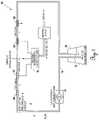
- FIG. 1shows a schematic detailing the present invention.
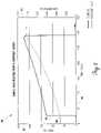
- FIG. 2shows a plot of the temperature (° F.) and current (A.U.) versus time (sec) of the present invention.
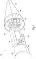
- FIG. 3is a cross sectional perspective view of an embodiment of the present invention.
- FIG. 4shows a partial perspective environmental view of an embodiment of the present invention integrated into an ice penetrating vehicle.
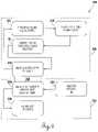
- FIG. 5is a flow chart of an embodiment of the present invention in the context of an ice penetrating vehicle.
- FIG. 6is a flow chart of an embodiment of the present invention in the context of a household residence.
- FIG. 1depicts a schematic 10 of a 10 kV high-voltage flow through heater.
- a 10 kV center tapped transformer 12produces 10 kV phase-to-phase and 5 kV phase-to-ground.
- Pump 14circulates conductive fluid 16 (in this case tap water) through non-conducting loop 18 .
- This loop 18is broken in four locations by conductive sections of tube 20 , 22 , 24 and 26 that act as electrical contacts to conductive fluid 16 . It is critical to note the outer contacts 20 and 26 are held at neutral/ground potential. Therefore, the input water and the output water are stripped of all common mode voltage.
- the inner two contacts 22 , 24are connected to the phase outputs of transformer 12 . Because the phase-to-neutral voltage is half (1 ⁇ 2) of the phase-to-phase voltage, the physical length between the phase-to-neutral is half (1 ⁇ 2) of the length of the phase-to-phase voltage. This maintains the resistance (and current) in each of the three flow-through resistors roughly constant. In reality, the resistance varies somewhat because the output water is hotter and of lower resistivity than the input water.
- Pump 14circulated conductive fluid 16 in loop 18 . The temperature rise is measured using thermocouples (not shown) in the input and exhaust water streams.
- the exhaust wateris completely stripped of all common mode voltage before returning to process fluid reservoir 28 .
- GFIground fault interrupter
- a graphical representation 30illustrates the relationship between the temperature and current of conductive fluid being heated using the present invention.
- Left axis 32represents the temperature (° F.).
- Right axis 34represents the current (A.U.).
- Bottom axis 36represents time (sec).
- Direct high voltage water heater 42has housing 44 having end plate 46 at one end. Fasteners 47 removably secure end plate 46 to housing 44 . Spacer or insulator 45 lines the inside surface of housing 44 , except for the areas in which heater electrodes element plates 58 , 60 , 62 and 64 traverse and separate insulator 45 .
- Insulator 45may be comprised of a polyether ether ketone (PEEK) material, though other comparable material may be used and still remain within the contemplation of the present invention.
- Housing 44 and end plate 46define a volume 68 .
- End plate 46contains intake port 48 through which conductive fluid, e.g., melt water, may enter and pass through volume 68 .
- the conductive fluidexits volume 68 at an elevated temperature (hot) via exhaust port 54 at the other end 52 of housing 44 .
- Insulator 56lines the interior surface (volume side) of end 52 .
- the present inventionuses an ethylene propylene diene monomer (EPDM) molded insulator, though other comparable material may be used.
- EPDMethylene propylene diene monomer
- Heater electrodes element plates 58 , 60 , 62 and 64are secured within volume 68 of housing 44 at a predetermined distance relative to each other. Each plate contains a plurality of apertures 66 through which conductive fluid may pass. Heater electrode element plates 58 , 60 , 62 and 64 are arranged from left to right. The first (leftmost) plate 58 is held at neutral potential, corresponding to the center tap of the high-voltage transformer (not shown). The spacing from first plate 58 to the next (second) plate 60 is distance L.
- the conductive fluid between plates 58 and 60is exposed to a voltage gradient equal to the line-to-neutral voltage of the transformer (not shown).
- this line-to-neutral voltageis 5 kVAC.
- the second and third plates 60 and 62are separated by distance 2L.
- Third plate 62is connected to line voltage L 2 which exposes the conductive fluid between second plate 60 and third plate 62 to the line-to-line voltage, which, in the present invention is 10 kV.
- Fourth plate 64is connected to neutral exposing the conductive fluid between third plate 62 and fourth plate 64 to the line-to-neutral gradient which is 5 kV. As the fluid passes through first plate 58 , all common mode voltage is stripped from the fluid rendering the exhaust fluid completely safe for personnel and for any electronic equipment which may come in contact with the exhaust fluid.
- housing 70having a top end 72 .
- Fasteners 74removably attach top end 72 to housing 70 to form volume 76 .
- Oil (not shown)fills volume 76 of housing 70 .
- Housing 70houses several feedthrough fittings 78 , 80 , 82 and 84 .
- Feedthrough fitting 86traverses housing 70 and connects to high voltage tether 88 .
- Feedthrough fitting 86also traverses housing 44 so as to be in electrical communication with heater electrodes element plates 58 , 60 , 62 and 64 .
- Insulated conductors 90 , 92 , 94 and 96connect feedthrough fittings 78 , 80 , 82 and 84 to high voltage tether 88 via feedthrough fitting 86 .
- the present inventionuses CONAX® feedthrough fittings and KAPTON® insulated conductors commercially available, though other comparable fittings and conductors may be used and still remain within the contemplation of the present invention.
- ground fault interruption circuitry(not shown) detects any current flow between housing 44 and safety ground. If current flow is detected, the fault is reported to mission control and the mission is suspended until further troubleshooting measures can be completed.
- the present inventionis shown integrated with an ice penetrator vehicle 98 (only a portion of which is shown).
- the present inventionutilizes a closed loop heater system that is in thermal communication through heat exchanger 100 with an open loop hot water drill.
- the primary heater looputilizes a process fluid pumped by process fluid pump 108 with a depressed freezing point so the vehicle 98 can restart even after being frozen in the ice for a long period of time.
- Primary loop circulationis accomplished by a high volume, low pressure centrifugal pump 108 .
- Process fluidtransits through the high-voltage heater core 42 and into the primary side of heat exchanger 100 .
- Meltwaterenters inlet ports via melt water intake 104 aft of nose cone 102 and is pumped through the secondary side of the heat exchanger 100 by a series of high pressure, high volume diaphragm pumps. After the water travels through heat exchanger 100 , the water is ejected from vehicle 98 via hot water to jet intake 114 in a series of jets 110 that can be turned on or off via a series of solenoid valves 112 .
- the present inventionmay be modified to operate at standard (low-voltage) residential/industrial mains voltages. This is accomplished by changing the spacing between the plates.
- the heaterruns from 220 VAC.
- the two outer plates 58 , 64are connected to neutral while the inner plates 60 , 62 are connected to line voltage L 1 and L 2 , respectively.
- Thisplaces a 110 VAC gradient across the outer plates 58 , 64 and places an 220 VAC gradient across the inner plates 60 , 62 .
- the exhaust fluidmust pass through the neutral plate 58 before exiting the heater 42 , stripping any common-mode voltage from the exhaust fluid.
- thermocouplein the exhaust port that closes a feedback loop to a controller (not shown).
- controllerpulse-width-modulates a silicon controlled rectifier (not shown), or zero switch crossing relay (not shown) on the mains voltage.
- Housing 44is bonded to earth-ground and ground-fault interruption circuitry monitors current flow from housing 44 to earth ground. Should the current flow exceed a preset threshold the circuitry disconnects direct high voltage water heater 42 from mains power via a mechanical relay. This supplements ground fault interruption circuitry on the 220 VAC mains.
- the present inventionmay be used as a stand-alone unit or incorporated into a high power cryobot or ice penetrating vehicle, in either scenario within a tightly enclosed and small space.
- the ice penetrating vehiclethat may be used with the direct high voltage fluid heater system of the present invention requires both a closed cycle heating system (which includes the heating element shown in FIG. 3 ) and an open loop system that draws fluid, such as water, in from the surrounding environment. This was because of the need to maintain a fluid in the heating loop that will not freeze and that had a specified electrolyte content to ensure the electrical power was dumped into the water—because if the vehicle stopped and power was turned off, the ambient water would freeze in the pipes and there would be no flow and it was uncertain whether the vehicle could start back up.
- a closed cycle heating systemwhich includes the heating element shown in FIG. 3
- an open loop systemthat draws fluid, such as water
- the present inventionfunctions equally proficient in both the case of heating fluids in an ice penetrating vehicle environment as it does in the residential household water heater environment regardless of external temperature or ambient water electrolyte or dissolved mineral content because a clean anti-freeze electrolyte is used in the closed (heating) part of the loop. So, in the instance where the fluid in the loop in FIG. 1 freezes (e.g., someone turns off the power temporarily and the water freezes in Alaska) then the power is turned back on, the system will work. In a similar context, if the ambient water (e.g., groundwater) has no electrolytes or is highly variable or contains too much in the way of dissolved minerals, e.g., limestone as may be found in Texas, the system will still work.
- the ambient watere.g., groundwater
- FIG. 5depicts flow chart 200 of the present invention having application in an ice penetrating vehicle.
- the vehiclecontains a closed cycle heating system 202 and an open loop system 204 .
- meltwater return 206enters heat exchanger melt water loop 208 .
- Heat transfer 218occurs between heat exchanger melt water loop 208 and heat exchanger process fluid loop 220 , with the direction of heat going from heat exchanger process fluid loop 220 to heat exchanger melt water loop 208 .
- Fluid in heat exchanger process fluid loop 220passes to process fluid reservoir 222 and then to process fluid pump—HVLP 224 , ultimately reaching and entering into direct high voltage fluid heater 42 where the fluid is heated. Once the fluid, now heated, flows through and exits direct high voltage fluid heater 42 , the fluid continues to heat exchanger process fluid loop 220 .
- heat transfer 218to heat exchanger melt water loop 208 , where the fluid, now heated, passes to high pressure jet pumps 210 and into routing valves and manifold 212 , finally directed to both forward and aft melting HWD jets 214 and 216 .
- flow chart 226depicts an alternative embodiment of the present invention having application for a house hot water heater.
- the house systemsimilarly contains a closed cycle heating system 228 and an open loop system 230 .
- open loop system 230water from the utility enters the system at water utility in 232 and enters heat exchanger house hot water tank 234 .
- Heat transfer 238occurs between heat exchanger house hot water tank 234 and heat exchanger process fluid loop 220 , with the direction of heat going from heat exchanger process fluid loop 220 to house hot water tank 234 .
- Fluid in heat exchanger process fluid loop 220passes to process fluid reservoir 222 and then to process fluid pump—HVLP 224 , ultimately reaching and entering into direct high voltage fluid heater 42 where the fluid is heated.
- HVLP 224process fluid pump—HVLP 224
- the fluidcontinues to heat exchanger process fluid loop 220 .
- the heatis transferred via heat transfer 238 to heat exchanger house hot water tank 234 , where the fluid, now heated, passes to house utilities 236 and is ready to be used by the consumer. Any heat exchanger that efficiently transfers the heat energy from the heat exchanger process fluid loop 220 (heated by the direct high voltage fluid heater 42 ) to the house hot water tank 234 will work.
Landscapes
- Engineering & Computer Science (AREA)
- Life Sciences & Earth Sciences (AREA)
- Mining & Mineral Resources (AREA)
- Geology (AREA)
- Physics & Mathematics (AREA)
- General Life Sciences & Earth Sciences (AREA)
- Environmental & Geological Engineering (AREA)
- Fluid Mechanics (AREA)
- Geochemistry & Mineralogy (AREA)
- General Engineering & Computer Science (AREA)
- Mechanical Engineering (AREA)
- Combustion & Propulsion (AREA)
- Chemical & Material Sciences (AREA)
- Thermal Sciences (AREA)
- Instantaneous Water Boilers, Portable Hot-Water Supply Apparatuses, And Control Of Portable Hot-Water Supply Apparatuses (AREA)
- Air-Conditioning For Vehicles (AREA)
- Resistance Heating (AREA)
- Control Of Resistance Heating (AREA)
Abstract
Description
Claims (6)
Priority Applications (2)
| Application Number | Priority Date | Filing Date | Title |
|---|---|---|---|
| US15/660,941US11493233B2 (en) | 2016-09-26 | 2017-07-26 | Direct high voltage water heater |
| US18/053,533US20230073890A1 (en) | 2016-09-26 | 2022-11-08 | Direct High Voltage Water Heater System |
Applications Claiming Priority (2)
| Application Number | Priority Date | Filing Date | Title |
|---|---|---|---|
| US201662399846P | 2016-09-26 | 2016-09-26 | |
| US15/660,941US11493233B2 (en) | 2016-09-26 | 2017-07-26 | Direct high voltage water heater |
Related Child Applications (1)
| Application Number | Title | Priority Date | Filing Date |
|---|---|---|---|
| US18/053,533ContinuationUS20230073890A1 (en) | 2016-09-26 | 2022-11-08 | Direct High Voltage Water Heater System |
Publications (2)
| Publication Number | Publication Date |
|---|---|
| US20180087804A1 US20180087804A1 (en) | 2018-03-29 |
| US11493233B2true US11493233B2 (en) | 2022-11-08 |
Family
ID=61688387
Family Applications (2)
| Application Number | Title | Priority Date | Filing Date |
|---|---|---|---|
| US15/660,941Active2038-01-19US11493233B2 (en) | 2016-09-26 | 2017-07-26 | Direct high voltage water heater |
| US18/053,533AbandonedUS20230073890A1 (en) | 2016-09-26 | 2022-11-08 | Direct High Voltage Water Heater System |
Family Applications After (1)
| Application Number | Title | Priority Date | Filing Date |
|---|---|---|---|
| US18/053,533AbandonedUS20230073890A1 (en) | 2016-09-26 | 2022-11-08 | Direct High Voltage Water Heater System |
Country Status (1)
| Country | Link |
|---|---|
| US (2) | US11493233B2 (en) |
Cited By (1)
| Publication number | Priority date | Publication date | Assignee | Title |
|---|---|---|---|---|
| US20230073890A1 (en)* | 2016-09-26 | 2023-03-09 | Stone Aerospace, Inc. | Direct High Voltage Water Heater System |
Families Citing this family (1)
| Publication number | Priority date | Publication date | Assignee | Title |
|---|---|---|---|---|
| CN108871848B (en)* | 2018-07-03 | 2020-08-14 | 国家海洋局第一海洋研究所 | An ice sample sampler |
Citations (81)
| Publication number | Priority date | Publication date | Assignee | Title |
|---|---|---|---|---|
| US1139669A (en) | 1914-02-04 | 1915-05-18 | Thomas H Gibbon | Egg-crate. |
| US1362356A (en) | 1920-12-14 | Instantaneous electbic wateb-heateb | ||
| US1827639A (en) | 1929-05-10 | 1931-10-13 | Boschetti Vincenzo | Heater |
| US1941584A (en)* | 1931-02-20 | 1934-01-02 | Sexton George Norrell | Electrical heater |
| US2481958A (en) | 1948-04-09 | 1949-09-13 | Videche Carlos | Fluid heater |
| US2807702A (en) | 1955-08-12 | 1957-09-24 | Manuel Lorenzo Y Gomez | Electric hot water heater |
| US3005083A (en)* | 1958-10-29 | 1961-10-17 | Lorenzo E Mendoza | Electro-heater |
| US3299252A (en)* | 1964-08-10 | 1967-01-17 | John E Meek | Electric fluid heating device |
| US3753537A (en) | 1969-10-09 | 1973-08-21 | Messerschmitt Boelkow Blohm | Method and apparatus for stabilizing the trajectory of a reaction-propelled missile |
| US3815511A (en) | 1973-04-26 | 1974-06-11 | Gen Motors Corp | Dc magnetic propulsion and levitation system for high speed vehicles |
| US3825211A (en) | 1972-06-19 | 1974-07-23 | Phaser Telepropulsion Inc | Laser rocket |
| US3946197A (en)* | 1973-07-24 | 1976-03-23 | Stanley Austen Williams | Electrode water heating boiler |
| US4029937A (en)* | 1974-10-04 | 1977-06-14 | Russell Robert G | Control system for electrically conductive liquid heating apparatus |
| US4730098A (en) | 1984-08-01 | 1988-03-08 | Cave Norman M | Electric electrode-type water heater |
| US4860968A (en) | 1988-04-15 | 1989-08-29 | The Boeing Company | Communication link between moving bodies |
| GB2196820B (en) | 1986-07-29 | 1990-01-24 | Dennis Albert Glover | Improvements in or relating to liquid heaters |
| US5022603A (en) | 1989-03-22 | 1991-06-11 | Societe Nationale Industrielle Et Aerospatiale | Coil of very long optical fibre usable on a wire-guided missile |
| US5039193A (en) | 1990-04-03 | 1991-08-13 | Focal Technologies Incorporated | Fibre optic single mode rotary joint |
| US5044573A (en) | 1989-06-23 | 1991-09-03 | Hughes Aircraft Company | Rotating drum filament dispenser |
| US5058969A (en) | 1990-05-09 | 1991-10-22 | Hughes Aircraft Company | Optical fiber dispensing system |
| US5074489A (en) | 1989-03-03 | 1991-12-24 | Eliyahu Gamzon | Method and system for supporting an airborne vehicle in space |
| US5099144A (en) | 1988-12-28 | 1992-03-24 | Kabushiki Kaisha Toshiba | Apparatus for optical power transmission and optically powered system |
| US5248931A (en) | 1991-07-31 | 1993-09-28 | The United States Of America As Represented By The Secretary Of The Navy | Laser energized high voltage direct current power supply |
| US5260639A (en) | 1992-01-06 | 1993-11-09 | The United States Of America As Represented By The Administrator Of The National Aeronautics And Space Administration | Method for remotely powering a device such as a lunar rover |
| US5310134A (en) | 1992-03-16 | 1994-05-10 | Hughes Aircraft Company | Tethered vehicle positioning system |
| US5436553A (en) | 1993-09-24 | 1995-07-25 | Tektronix, Inc. | Optical power conversion |
| US5440667A (en) | 1990-04-10 | 1995-08-08 | Electricity Association Technology Limited | OHMIC heater including electrodes arranged along a flow axis to reduce leakage current |
| US5490973A (en)* | 1994-05-23 | 1996-02-13 | The United States Of America As Represented By The Secretary Of The Navy | Pulsed corona reactor system for abatement of pollution by hazardous agents |
| US5502356A (en) | 1994-05-02 | 1996-03-26 | Plex Corporation | Stabilized radial pseudospark switch |
| US5564649A (en) | 1994-04-27 | 1996-10-15 | Daimler-Benz Aerospace Ag | Apparatus for the remote control of missiles or torpedoes |
| US5686694A (en) | 1995-10-11 | 1997-11-11 | The United States Of America As Represented By The Secretary Of The Navy | Unmanned undersea vehicle with erectable sensor mast for obtaining position and environmental vehicle status |
| US5748102A (en) | 1995-09-19 | 1998-05-05 | The United States Of America As Represented By The Secretary Of The Navy | Apparatus for interconnecting an underwater vehicle and a free floating communications pod |
| US6167831B1 (en) | 1999-09-20 | 2001-01-02 | Coflexip S.A. | Underwater vehicle |
| US6223675B1 (en) | 1999-09-20 | 2001-05-01 | Coflexip, S.A. | Underwater power and data relay |
| JP2001132542A (en) | 1999-11-09 | 2001-05-15 | Natl Aerospace Lab | Engine system using laser light |
| NZ510301A (en)* | 1999-04-19 | 2001-06-29 | Sherwood Templeton Coal Compan | Flow through water heater ground fault protection |
| US6257162B1 (en) | 1999-09-20 | 2001-07-10 | Coflexip, S.A. | Underwater latch and power supply |
| US6262357B1 (en) | 1998-08-27 | 2001-07-17 | International Business Machines Corporation | Thermoelectric devices and methods for making the same |
| US6307156B1 (en) | 1997-05-02 | 2001-10-23 | General Science And Technology Corp. | High flexibility and heat dissipating coaxial cable |
| US20020046763A1 (en) | 2000-10-23 | 2002-04-25 | Jesus Berrios | Methods and apparatus for beaming power |
| US6390012B1 (en) | 1999-09-20 | 2002-05-21 | Coflexip, S.A. | Apparatus and method for deploying, recovering, servicing, and operating an autonomous underwater vehicle |
| US6407535B1 (en) | 2000-09-08 | 2002-06-18 | The Regents Of The University Of California | System for beaming power from earth to a high altitude platform |
| US6411565B1 (en) | 2001-05-11 | 2002-06-25 | The United States Of America As Represented By The Secretary Of The Navy | Multi-use torpedo dispensed single mode optical fiber |
| JP2002193555A (en) | 2000-12-27 | 2002-07-10 | Fujikura Ltd | Power supply cable reel device and cable reel for mobile equipment |
| US6488233B1 (en) | 2001-04-30 | 2002-12-03 | The United States Of America As Represented By The Secretary Of The Air Force | Laser propelled vehicle |
| US6491258B1 (en) | 1999-04-05 | 2002-12-10 | Lockheed Martin Corporation | Space elevator |
| US20030111660A1 (en) | 2001-12-12 | 2003-06-19 | Saied Ghamaty | Thermoelectric device with Si/SiC superlattice N-legs |
| KR20030057767A (en)* | 2001-12-29 | 2003-07-07 | 김동암 | Do heating chapter the water moment that use induced current |
| US6669126B1 (en) | 1998-12-18 | 2003-12-30 | Lfk-Lenkflugkorpersysteme Gmbh | Payout device for data transmission lines and method for the production of payout device |
| US20040149485A1 (en) | 2002-08-08 | 2004-08-05 | Edwards Bradley C | Cable for a space elevator |
| US20040163709A1 (en) | 2003-02-24 | 2004-08-26 | Baugh Benton F. | Fluid swivel with cooling porting |
| US20040163802A1 (en) | 2003-02-24 | 2004-08-26 | Baugh Benton F. | Multi-channel high pressure swivel |
| US20040182732A1 (en) | 2003-03-18 | 2004-09-23 | Zamel James M. | Compact packaging of multiple fiber lasers |
| US20040238022A1 (en) | 2001-12-12 | 2004-12-02 | Hiller Nathan D. | Thermoelectric power from environmental temperature cycles |
| US20050028857A1 (en) | 2001-12-12 | 2005-02-10 | Saeid Ghamaty | Thermoelectric module with Si/SiC and B4C/B9C super-lattice legs |
| US20050126624A1 (en) | 2003-12-11 | 2005-06-16 | Chrysalis Technologies, Inc. | Hybrid system for generating power |
| US6910658B1 (en) | 1988-12-08 | 2005-06-28 | Bae Systems Plc | Underwater detection system |
| US6964509B2 (en) | 2003-12-16 | 2005-11-15 | 3M Innovative Properties Company | Task lighting system |
| US20060289724A1 (en) | 2005-06-20 | 2006-12-28 | Skinner Neal G | Fiber optic sensor capable of using optical power to sense a parameter |
| US20070056262A1 (en) | 2003-06-25 | 2007-03-15 | Rachel Leach | Laser propulsion thruster |
| US7263245B2 (en) | 2005-03-14 | 2007-08-28 | The Boeing Company | Method and apparatus for optically powering and multiplexing distributed fiber optic sensors |
| US20080056642A1 (en) | 2006-09-01 | 2008-03-06 | Mobius Photonics, Inc. | Reducing thermal load on optical head |
| US20080134952A1 (en) | 2005-03-16 | 2008-06-12 | Michael Alan Tull | Underwater Vehicles |
| US20090086309A1 (en) | 2007-09-28 | 2009-04-02 | Jurgen Moosburger | Source of light with conversion element and fiber optics, procedure for the production of the source of light and their use |
| US7540265B2 (en) | 2004-05-19 | 2009-06-02 | Peugeot Citroen Automobiles Sa | Valve actuating device |
| US20090206697A1 (en) | 2007-08-06 | 2009-08-20 | Marshall Bruce C | Method for generating, transmitting and receiving power |
| US20090251271A1 (en) | 2008-04-03 | 2009-10-08 | Gerald Stelzer | Structure For A Wiring Assembly And Method Suitable For Forming Multiple Coil Rows With Splice Free Conductor |
| US20090296746A1 (en) | 2008-03-15 | 2009-12-03 | Morgan Research Corporation | Fiber laser coil form and related manufacturing techniques |
| US20100044106A1 (en) | 2008-08-20 | 2010-02-25 | Zediker Mark S | Method and apparatus for delivering high power laser energy over long distances |
| US20100215326A1 (en) | 2008-10-17 | 2010-08-26 | Zediker Mark S | Optical Fiber Cable for Transmission of High Power Laser Energy Over Great Distances |
| US20100275576A1 (en) | 2009-05-04 | 2010-11-04 | Technion - Research & Development Foundation Ltd. | System and method for maneuvering rockets |
| US20100322605A1 (en)* | 2008-02-11 | 2010-12-23 | Robert Cornelis Van Aken | Segmented rapid heating of fluid |
| US20120068086A1 (en) | 2008-08-20 | 2012-03-22 | Dewitt Ronald A | Systems and conveyance structures for high power long distance laser transmission |
| US20130099182A1 (en)* | 2011-10-07 | 2013-04-25 | E I Du Pont De Nemours And Company | Liquid compositions used as insulating and heat transfer means, electrical devices containing said compositions and preparation method for such compositions |
| US8532474B2 (en) | 2008-03-05 | 2013-09-10 | Mark E. Campbell | Molecular heater and method of heating fluids |
| CN203464470U (en)* | 2013-07-05 | 2014-03-05 | 侯马经济开发区盛海机电设备有限公司 | Electric water heater |
| CN104110835A (en)* | 2014-04-10 | 2014-10-22 | 芜湖美的厨卫电器制造有限公司 | Electric water heater |
| CN104534673A (en)* | 2014-12-16 | 2015-04-22 | 爱科奔(大连)电器有限公司 | Induced current fluid induction heating device and water supply system with same |
| US20160000262A1 (en)* | 2014-07-03 | 2016-01-07 | B/E Aerospace, Inc. | Multi-phase circuit flow-through heater for aerospace beverage maker |
| US20160049781A1 (en)* | 2014-08-14 | 2016-02-18 | Schott Ag | Electrical feed-through and the use thereof |
| US20170153022A1 (en)* | 2014-06-20 | 2017-06-01 | 3278470 Nova Scotia Limited | Electrode water heater |
Family Cites Families (2)
| Publication number | Priority date | Publication date | Assignee | Title |
|---|---|---|---|---|
| US1357019A (en)* | 1918-09-26 | 1920-10-26 | Alexander Eaton Woods | Electrically-heated water service and system |
| US11493233B2 (en)* | 2016-09-26 | 2022-11-08 | Stone Aerospace, Inc. | Direct high voltage water heater |
- 2017
- 2017-07-26USUS15/660,941patent/US11493233B2/enactiveActive
- 2022
- 2022-11-08USUS18/053,533patent/US20230073890A1/ennot_activeAbandoned
Patent Citations (91)
| Publication number | Priority date | Publication date | Assignee | Title |
|---|---|---|---|---|
| US1362356A (en) | 1920-12-14 | Instantaneous electbic wateb-heateb | ||
| US1139669A (en) | 1914-02-04 | 1915-05-18 | Thomas H Gibbon | Egg-crate. |
| US1827639A (en) | 1929-05-10 | 1931-10-13 | Boschetti Vincenzo | Heater |
| US1941584A (en)* | 1931-02-20 | 1934-01-02 | Sexton George Norrell | Electrical heater |
| US2481958A (en) | 1948-04-09 | 1949-09-13 | Videche Carlos | Fluid heater |
| US2807702A (en) | 1955-08-12 | 1957-09-24 | Manuel Lorenzo Y Gomez | Electric hot water heater |
| US3005083A (en)* | 1958-10-29 | 1961-10-17 | Lorenzo E Mendoza | Electro-heater |
| US3299252A (en)* | 1964-08-10 | 1967-01-17 | John E Meek | Electric fluid heating device |
| US3753537A (en) | 1969-10-09 | 1973-08-21 | Messerschmitt Boelkow Blohm | Method and apparatus for stabilizing the trajectory of a reaction-propelled missile |
| US3825211A (en) | 1972-06-19 | 1974-07-23 | Phaser Telepropulsion Inc | Laser rocket |
| US3815511A (en) | 1973-04-26 | 1974-06-11 | Gen Motors Corp | Dc magnetic propulsion and levitation system for high speed vehicles |
| US3946197A (en)* | 1973-07-24 | 1976-03-23 | Stanley Austen Williams | Electrode water heating boiler |
| US4029937A (en)* | 1974-10-04 | 1977-06-14 | Russell Robert G | Control system for electrically conductive liquid heating apparatus |
| US4730098A (en) | 1984-08-01 | 1988-03-08 | Cave Norman M | Electric electrode-type water heater |
| GB2196820B (en) | 1986-07-29 | 1990-01-24 | Dennis Albert Glover | Improvements in or relating to liquid heaters |
| US4860968A (en) | 1988-04-15 | 1989-08-29 | The Boeing Company | Communication link between moving bodies |
| US6910658B1 (en) | 1988-12-08 | 2005-06-28 | Bae Systems Plc | Underwater detection system |
| US5099144A (en) | 1988-12-28 | 1992-03-24 | Kabushiki Kaisha Toshiba | Apparatus for optical power transmission and optically powered system |
| US5074489A (en) | 1989-03-03 | 1991-12-24 | Eliyahu Gamzon | Method and system for supporting an airborne vehicle in space |
| US5022603A (en) | 1989-03-22 | 1991-06-11 | Societe Nationale Industrielle Et Aerospatiale | Coil of very long optical fibre usable on a wire-guided missile |
| US5044573A (en) | 1989-06-23 | 1991-09-03 | Hughes Aircraft Company | Rotating drum filament dispenser |
| US5039193A (en) | 1990-04-03 | 1991-08-13 | Focal Technologies Incorporated | Fibre optic single mode rotary joint |
| US5440667A (en) | 1990-04-10 | 1995-08-08 | Electricity Association Technology Limited | OHMIC heater including electrodes arranged along a flow axis to reduce leakage current |
| US5058969A (en) | 1990-05-09 | 1991-10-22 | Hughes Aircraft Company | Optical fiber dispensing system |
| US5248931A (en) | 1991-07-31 | 1993-09-28 | The United States Of America As Represented By The Secretary Of The Navy | Laser energized high voltage direct current power supply |
| US5260639A (en) | 1992-01-06 | 1993-11-09 | The United States Of America As Represented By The Administrator Of The National Aeronautics And Space Administration | Method for remotely powering a device such as a lunar rover |
| US5310134A (en) | 1992-03-16 | 1994-05-10 | Hughes Aircraft Company | Tethered vehicle positioning system |
| US5436553A (en) | 1993-09-24 | 1995-07-25 | Tektronix, Inc. | Optical power conversion |
| US5564649A (en) | 1994-04-27 | 1996-10-15 | Daimler-Benz Aerospace Ag | Apparatus for the remote control of missiles or torpedoes |
| US5502356A (en) | 1994-05-02 | 1996-03-26 | Plex Corporation | Stabilized radial pseudospark switch |
| US5490973A (en)* | 1994-05-23 | 1996-02-13 | The United States Of America As Represented By The Secretary Of The Navy | Pulsed corona reactor system for abatement of pollution by hazardous agents |
| US5748102A (en) | 1995-09-19 | 1998-05-05 | The United States Of America As Represented By The Secretary Of The Navy | Apparatus for interconnecting an underwater vehicle and a free floating communications pod |
| US5686694A (en) | 1995-10-11 | 1997-11-11 | The United States Of America As Represented By The Secretary Of The Navy | Unmanned undersea vehicle with erectable sensor mast for obtaining position and environmental vehicle status |
| US6307156B1 (en) | 1997-05-02 | 2001-10-23 | General Science And Technology Corp. | High flexibility and heat dissipating coaxial cable |
| US6262357B1 (en) | 1998-08-27 | 2001-07-17 | International Business Machines Corporation | Thermoelectric devices and methods for making the same |
| US6669126B1 (en) | 1998-12-18 | 2003-12-30 | Lfk-Lenkflugkorpersysteme Gmbh | Payout device for data transmission lines and method for the production of payout device |
| US6491258B1 (en) | 1999-04-05 | 2002-12-10 | Lockheed Martin Corporation | Space elevator |
| NZ510301A (en)* | 1999-04-19 | 2001-06-29 | Sherwood Templeton Coal Compan | Flow through water heater ground fault protection |
| US6257162B1 (en) | 1999-09-20 | 2001-07-10 | Coflexip, S.A. | Underwater latch and power supply |
| US6390012B1 (en) | 1999-09-20 | 2002-05-21 | Coflexip, S.A. | Apparatus and method for deploying, recovering, servicing, and operating an autonomous underwater vehicle |
| US6223675B1 (en) | 1999-09-20 | 2001-05-01 | Coflexip, S.A. | Underwater power and data relay |
| US6167831B1 (en) | 1999-09-20 | 2001-01-02 | Coflexip S.A. | Underwater vehicle |
| JP2001132542A (en) | 1999-11-09 | 2001-05-15 | Natl Aerospace Lab | Engine system using laser light |
| US6407535B1 (en) | 2000-09-08 | 2002-06-18 | The Regents Of The University Of California | System for beaming power from earth to a high altitude platform |
| US20020046763A1 (en) | 2000-10-23 | 2002-04-25 | Jesus Berrios | Methods and apparatus for beaming power |
| US6534705B2 (en) | 2000-10-23 | 2003-03-18 | Power Beaming Corporation | Methods and apparatus for beaming power |
| JP2002193555A (en) | 2000-12-27 | 2002-07-10 | Fujikura Ltd | Power supply cable reel device and cable reel for mobile equipment |
| US6488233B1 (en) | 2001-04-30 | 2002-12-03 | The United States Of America As Represented By The Secretary Of The Air Force | Laser propelled vehicle |
| US6411565B1 (en) | 2001-05-11 | 2002-06-25 | The United States Of America As Represented By The Secretary Of The Navy | Multi-use torpedo dispensed single mode optical fiber |
| US6914343B2 (en) | 2001-12-12 | 2005-07-05 | Hi-Z Technology, Inc. | Thermoelectric power from environmental temperature cycles |
| US20030111660A1 (en) | 2001-12-12 | 2003-06-19 | Saied Ghamaty | Thermoelectric device with Si/SiC superlattice N-legs |
| US20040238022A1 (en) | 2001-12-12 | 2004-12-02 | Hiller Nathan D. | Thermoelectric power from environmental temperature cycles |
| US6828579B2 (en) | 2001-12-12 | 2004-12-07 | Hi-Z Technology, Inc. | Thermoelectric device with Si/SiC superlattice N-legs |
| US20050028857A1 (en) | 2001-12-12 | 2005-02-10 | Saeid Ghamaty | Thermoelectric module with Si/SiC and B4C/B9C super-lattice legs |
| US7342170B2 (en) | 2001-12-12 | 2008-03-11 | Hi-Z Technology, Inc. | Thermoelectric module with Si/SiC and B4 C/B9 C super-lattice legs |
| KR20030057767A (en)* | 2001-12-29 | 2003-07-07 | 김동암 | Do heating chapter the water moment that use induced current |
| US20040149485A1 (en) | 2002-08-08 | 2004-08-05 | Edwards Bradley C | Cable for a space elevator |
| US20040163709A1 (en) | 2003-02-24 | 2004-08-26 | Baugh Benton F. | Fluid swivel with cooling porting |
| US20040163802A1 (en) | 2003-02-24 | 2004-08-26 | Baugh Benton F. | Multi-channel high pressure swivel |
| US20040182732A1 (en) | 2003-03-18 | 2004-09-23 | Zamel James M. | Compact packaging of multiple fiber lasers |
| US6968112B2 (en) | 2003-03-18 | 2005-11-22 | Northrop Grumman Corporation | Compact packaging of multiple fiber lasers |
| US20070056262A1 (en) | 2003-06-25 | 2007-03-15 | Rachel Leach | Laser propulsion thruster |
| US20050126624A1 (en) | 2003-12-11 | 2005-06-16 | Chrysalis Technologies, Inc. | Hybrid system for generating power |
| US6964509B2 (en) | 2003-12-16 | 2005-11-15 | 3M Innovative Properties Company | Task lighting system |
| US7540265B2 (en) | 2004-05-19 | 2009-06-02 | Peugeot Citroen Automobiles Sa | Valve actuating device |
| US7263245B2 (en) | 2005-03-14 | 2007-08-28 | The Boeing Company | Method and apparatus for optically powering and multiplexing distributed fiber optic sensors |
| US7356209B2 (en) | 2005-03-14 | 2008-04-08 | Boeing Company | Method and apparatus for optically powering and multiplexing distributed fiber optic sensors |
| US20080134952A1 (en) | 2005-03-16 | 2008-06-12 | Michael Alan Tull | Underwater Vehicles |
| US20060289724A1 (en) | 2005-06-20 | 2006-12-28 | Skinner Neal G | Fiber optic sensor capable of using optical power to sense a parameter |
| US20080056642A1 (en) | 2006-09-01 | 2008-03-06 | Mobius Photonics, Inc. | Reducing thermal load on optical head |
| US20090206697A1 (en) | 2007-08-06 | 2009-08-20 | Marshall Bruce C | Method for generating, transmitting and receiving power |
| US20090086309A1 (en) | 2007-09-28 | 2009-04-02 | Jurgen Moosburger | Source of light with conversion element and fiber optics, procedure for the production of the source of light and their use |
| US20100322605A1 (en)* | 2008-02-11 | 2010-12-23 | Robert Cornelis Van Aken | Segmented rapid heating of fluid |
| US8532474B2 (en) | 2008-03-05 | 2013-09-10 | Mark E. Campbell | Molecular heater and method of heating fluids |
| US20090296746A1 (en) | 2008-03-15 | 2009-12-03 | Morgan Research Corporation | Fiber laser coil form and related manufacturing techniques |
| US20090251271A1 (en) | 2008-04-03 | 2009-10-08 | Gerald Stelzer | Structure For A Wiring Assembly And Method Suitable For Forming Multiple Coil Rows With Splice Free Conductor |
| US20100044106A1 (en) | 2008-08-20 | 2010-02-25 | Zediker Mark S | Method and apparatus for delivering high power laser energy over long distances |
| US20100044103A1 (en) | 2008-08-20 | 2010-02-25 | Moxley Joel F | Method and system for advancement of a borehole using a high power laser |
| US20120068086A1 (en) | 2008-08-20 | 2012-03-22 | Dewitt Ronald A | Systems and conveyance structures for high power long distance laser transmission |
| US20100215326A1 (en) | 2008-10-17 | 2010-08-26 | Zediker Mark S | Optical Fiber Cable for Transmission of High Power Laser Energy Over Great Distances |
| US20100275576A1 (en) | 2009-05-04 | 2010-11-04 | Technion - Research & Development Foundation Ltd. | System and method for maneuvering rockets |
| US20130099182A1 (en)* | 2011-10-07 | 2013-04-25 | E I Du Pont De Nemours And Company | Liquid compositions used as insulating and heat transfer means, electrical devices containing said compositions and preparation method for such compositions |
| CN203464470U (en)* | 2013-07-05 | 2014-03-05 | 侯马经济开发区盛海机电设备有限公司 | Electric water heater |
| CN104110835A (en)* | 2014-04-10 | 2014-10-22 | 芜湖美的厨卫电器制造有限公司 | Electric water heater |
| US20170153022A1 (en)* | 2014-06-20 | 2017-06-01 | 3278470 Nova Scotia Limited | Electrode water heater |
| US10281138B2 (en)* | 2014-06-20 | 2019-05-07 | 3278470 Nova Scotia Limited | Electrode water heater |
| US20160000262A1 (en)* | 2014-07-03 | 2016-01-07 | B/E Aerospace, Inc. | Multi-phase circuit flow-through heater for aerospace beverage maker |
| US10524611B2 (en)* | 2014-07-03 | 2020-01-07 | B/E Aerospace, Inc. | Multi-phase circuit flow-through heater for aerospace beverage maker |
| US20160049781A1 (en)* | 2014-08-14 | 2016-02-18 | Schott Ag | Electrical feed-through and the use thereof |
| US9577416B2 (en)* | 2014-08-14 | 2017-02-21 | Schott Ag | Electrical feed-through and the use thereof |
| CN104534673A (en)* | 2014-12-16 | 2015-04-22 | 爱科奔(大连)电器有限公司 | Induced current fluid induction heating device and water supply system with same |
Non-Patent Citations (5)
| Title |
|---|
| Dughaish, Z.H., Lead telluride as a thermoelectric material for thermoelectric power generation, Physica 8: Condensed Matter, vol. 322, Issues 1-2, 2002, pp. 205-223. |
| Hecht, Jeff, Photonic Frontiers: Photonic power delivery: Photonic power conversion delivers power via laser beams, 2006, Laser Focus World, available at https://www.laserfocusworld.com/articles/print!volume-42/issue-1/features/photonic-frontiersphotonic-power-delivery-photonic-power-conversion-delivers-power-via-laser-beams.html. |
| Hussein, H., A novel delivery for laser thermal recanalization, Images of the Twenty-First Century. Proceedings of the Annual International Engineering in Medicine and Biology Society, Seattle, WA, 1989, pp. 1190-1191 vol. 4. |
| Lorenz, R.D., Subsurface ambient thermoelectric power for moles and penetrators, 2003 IEEE Aerospace Conference Proceedings (Cat. No.03TH8652), 2003, pp. 2_637-2_642. |
| Ritz et al., Multi-mission radioisotope thermoelectric generator (MMRTG) program overview, 20041EEE Aerospace Conference Proceedings (IEEE Cat. No.04TH8720), 2004, pp. 2957 vol.5. |
Cited By (1)
| Publication number | Priority date | Publication date | Assignee | Title |
|---|---|---|---|---|
| US20230073890A1 (en)* | 2016-09-26 | 2023-03-09 | Stone Aerospace, Inc. | Direct High Voltage Water Heater System |
Also Published As
| Publication number | Publication date |
|---|---|
| US20230073890A1 (en) | 2023-03-09 |
| US20180087804A1 (en) | 2018-03-29 |
Similar Documents
| Publication | Publication Date | Title |
|---|---|---|
| US20230073890A1 (en) | Direct High Voltage Water Heater System | |
| RU2292676C2 (en) | System for sea extraction of oil, method for modifying existing underwater pipeline with heating system | |
| US12427559B2 (en) | Electromagnetic induction heater | |
| CN102124281B (en) | Rapid liquid heating | |
| US11174995B2 (en) | Hydrate remediation systems, apparatuses and methods of making and using same | |
| US9786431B2 (en) | Electrical power and/or electrical signal transmission | |
| US8354010B2 (en) | Electrolytic cell with cavitating jet | |
| EP3262663B1 (en) | Subsea transformer with seawater high resistance ground | |
| JP2023507913A (en) | Electrode heating element, electrode heating device including the same, and leakage prevention control method applied thereto | |
| WO2004111519A1 (en) | Method and system for direct electric heating of a pipeline | |
| WO2013025208A1 (en) | Steam generator system | |
| CA1053179A (en) | Electric treater system | |
| RU2662635C2 (en) | Induction-resistive electric heating system | |
| US10281138B2 (en) | Electrode water heater | |
| CN204962146U (en) | Heating system of intelligent transfusion pipeline | |
| CN102401420A (en) | Frequency conversion electromagnetic heater | |
| CA2864854A1 (en) | Heating element | |
| RU2095945C1 (en) | Electrode heater of liquids | |
| CN204962145U (en) | System is with fixed attention separated to intelligent electric induction of pipeline of condensing | |
| CN200987223Y (en) | Interior heat type pipe electromagnetic heater | |
| RU2451235C2 (en) | Ohmic screening pulsating current sensor | |
| CN202955869U (en) | Water box of electromagnetic water heater | |
| RU2431861C1 (en) | Universal disposable cartridge of bottom station disconnector | |
| CN118151043A (en) | A comprehensive detection system for underwater lighting fixtures | |
| HK40000840A (en) | Electromagnetic induction heater |
Legal Events
| Date | Code | Title | Description |
|---|---|---|---|
| AS | Assignment | Owner name:STONE AEROSPACE, INC., TEXAS Free format text:ASSIGNMENT OF ASSIGNORS INTEREST;ASSIGNOR:STONE, WILLIAM C.;REEL/FRAME:043323/0043 Effective date:20170801 | |
| STPP | Information on status: patent application and granting procedure in general | Free format text:DOCKETED NEW CASE - READY FOR EXAMINATION | |
| AS | Assignment | Owner name:PIEDRA-SOMBRA CORPORATION, INC., TEXAS Free format text:ASSIGNMENT OF ASSIGNORS INTEREST;ASSIGNORS:HARMAN, JOHN;SMITH, FRED;REEL/FRAME:045893/0489 Effective date:20180521 Owner name:STONE AEROSPACE, INC., TEXAS Free format text:CHANGE OF NAME;ASSIGNOR:PIEDRA-SOMBRA CORPORATION, INC.;REEL/FRAME:046231/0588 Effective date:20170117 | |
| STPP | Information on status: patent application and granting procedure in general | Free format text:NON FINAL ACTION MAILED | |
| STPP | Information on status: patent application and granting procedure in general | Free format text:RESPONSE TO NON-FINAL OFFICE ACTION ENTERED AND FORWARDED TO EXAMINER | |
| STPP | Information on status: patent application and granting procedure in general | Free format text:FINAL REJECTION MAILED | |
| STPP | Information on status: patent application and granting procedure in general | Free format text:DOCKETED NEW CASE - READY FOR EXAMINATION | |
| STPP | Information on status: patent application and granting procedure in general | Free format text:PUBLICATIONS -- ISSUE FEE PAYMENT RECEIVED | |
| STPP | Information on status: patent application and granting procedure in general | Free format text:PUBLICATIONS -- ISSUE FEE PAYMENT VERIFIED | |
| STCF | Information on status: patent grant | Free format text:PATENTED CASE |