US11491884B2 - Magnetic charger connector for wheelchair - Google Patents
Magnetic charger connector for wheelchairDownload PDFInfo
- Publication number
- US11491884B2 US11491884B2US16/559,782US201916559782AUS11491884B2US 11491884 B2US11491884 B2US 11491884B2US 201916559782 AUS201916559782 AUS 201916559782AUS 11491884 B2US11491884 B2US 11491884B2
- Authority
- US
- United States
- Prior art keywords
- magnets
- connector
- charger
- electrical
- housing
- Prior art date
- Legal status (The legal status is an assumption and is not a legal conclusion. Google has not performed a legal analysis and makes no representation as to the accuracy of the status listed.)
- Active, expires
Links
- 230000005611electricityEffects0.000claimsdescription12
- 239000004020conductorSubstances0.000claimsdescription10
- 238000001514detection methodMethods0.000claimsdescription5
- 230000006870functionEffects0.000description42
- 238000010586diagramMethods0.000description7
- 238000000034methodMethods0.000description6
- 238000013461designMethods0.000description5
- 230000013011matingEffects0.000description3
- 238000013459approachMethods0.000description2
- 238000011109contaminationMethods0.000description2
- 230000000694effectsEffects0.000description2
- 238000012986modificationMethods0.000description2
- 230000004048modificationEffects0.000description2
- 230000010287polarizationEffects0.000description2
- 238000006243chemical reactionMethods0.000description1
- 238000004590computer programMethods0.000description1
- 230000003750conditioning effectEffects0.000description1
- 238000011161developmentMethods0.000description1
- 230000018109developmental processEffects0.000description1
- 230000009977dual effectEffects0.000description1
- 230000014759maintenance of locationEffects0.000description1
- 239000000463materialSubstances0.000description1
- 230000005055memory storageEffects0.000description1
- 238000005476solderingMethods0.000description1
Images


Classifications
- B—PERFORMING OPERATIONS; TRANSPORTING
- B60—VEHICLES IN GENERAL
- B60L—PROPULSION OF ELECTRICALLY-PROPELLED VEHICLES; SUPPLYING ELECTRIC POWER FOR AUXILIARY EQUIPMENT OF ELECTRICALLY-PROPELLED VEHICLES; ELECTRODYNAMIC BRAKE SYSTEMS FOR VEHICLES IN GENERAL; MAGNETIC SUSPENSION OR LEVITATION FOR VEHICLES; MONITORING OPERATING VARIABLES OF ELECTRICALLY-PROPELLED VEHICLES; ELECTRIC SAFETY DEVICES FOR ELECTRICALLY-PROPELLED VEHICLES
- B60L53/00—Methods of charging batteries, specially adapted for electric vehicles; Charging stations or on-board charging equipment therefor; Exchange of energy storage elements in electric vehicles
- B60L53/10—Methods of charging batteries, specially adapted for electric vehicles; Charging stations or on-board charging equipment therefor; Exchange of energy storage elements in electric vehicles characterised by the energy transfer between the charging station and the vehicle
- B60L53/14—Conductive energy transfer
- B60L53/16—Connectors, e.g. plugs or sockets, specially adapted for charging electric vehicles
- B—PERFORMING OPERATIONS; TRANSPORTING
- B60—VEHICLES IN GENERAL
- B60L—PROPULSION OF ELECTRICALLY-PROPELLED VEHICLES; SUPPLYING ELECTRIC POWER FOR AUXILIARY EQUIPMENT OF ELECTRICALLY-PROPELLED VEHICLES; ELECTRODYNAMIC BRAKE SYSTEMS FOR VEHICLES IN GENERAL; MAGNETIC SUSPENSION OR LEVITATION FOR VEHICLES; MONITORING OPERATING VARIABLES OF ELECTRICALLY-PROPELLED VEHICLES; ELECTRIC SAFETY DEVICES FOR ELECTRICALLY-PROPELLED VEHICLES
- B60L50/00—Electric propulsion with power supplied within the vehicle
- B60L50/50—Electric propulsion with power supplied within the vehicle using propulsion power supplied by batteries or fuel cells
- B60L50/60—Electric propulsion with power supplied within the vehicle using propulsion power supplied by batteries or fuel cells using power supplied by batteries
- B—PERFORMING OPERATIONS; TRANSPORTING
- B60—VEHICLES IN GENERAL
- B60L—PROPULSION OF ELECTRICALLY-PROPELLED VEHICLES; SUPPLYING ELECTRIC POWER FOR AUXILIARY EQUIPMENT OF ELECTRICALLY-PROPELLED VEHICLES; ELECTRODYNAMIC BRAKE SYSTEMS FOR VEHICLES IN GENERAL; MAGNETIC SUSPENSION OR LEVITATION FOR VEHICLES; MONITORING OPERATING VARIABLES OF ELECTRICALLY-PROPELLED VEHICLES; ELECTRIC SAFETY DEVICES FOR ELECTRICALLY-PROPELLED VEHICLES
- B60L53/00—Methods of charging batteries, specially adapted for electric vehicles; Charging stations or on-board charging equipment therefor; Exchange of energy storage elements in electric vehicles
- B60L53/10—Methods of charging batteries, specially adapted for electric vehicles; Charging stations or on-board charging equipment therefor; Exchange of energy storage elements in electric vehicles characterised by the energy transfer between the charging station and the vehicle
- B60L53/14—Conductive energy transfer
- B60L53/18—Cables specially adapted for charging electric vehicles
- H—ELECTRICITY
- H01—ELECTRIC ELEMENTS
- H01R—ELECTRICALLY-CONDUCTIVE CONNECTIONS; STRUCTURAL ASSOCIATIONS OF A PLURALITY OF MUTUALLY-INSULATED ELECTRICAL CONNECTING ELEMENTS; COUPLING DEVICES; CURRENT COLLECTORS
- H01R13/00—Details of coupling devices of the kinds covered by groups H01R12/70 or H01R24/00 - H01R33/00
- H01R13/62—Means for facilitating engagement or disengagement of coupling parts or for holding them in engagement
- H01R13/6205—Two-part coupling devices held in engagement by a magnet
- B—PERFORMING OPERATIONS; TRANSPORTING
- B60—VEHICLES IN GENERAL
- B60L—PROPULSION OF ELECTRICALLY-PROPELLED VEHICLES; SUPPLYING ELECTRIC POWER FOR AUXILIARY EQUIPMENT OF ELECTRICALLY-PROPELLED VEHICLES; ELECTRODYNAMIC BRAKE SYSTEMS FOR VEHICLES IN GENERAL; MAGNETIC SUSPENSION OR LEVITATION FOR VEHICLES; MONITORING OPERATING VARIABLES OF ELECTRICALLY-PROPELLED VEHICLES; ELECTRIC SAFETY DEVICES FOR ELECTRICALLY-PROPELLED VEHICLES
- B60L2200/00—Type of vehicles
- B60L2200/34—Wheel chairs
- B—PERFORMING OPERATIONS; TRANSPORTING
- B60—VEHICLES IN GENERAL
- B60L—PROPULSION OF ELECTRICALLY-PROPELLED VEHICLES; SUPPLYING ELECTRIC POWER FOR AUXILIARY EQUIPMENT OF ELECTRICALLY-PROPELLED VEHICLES; ELECTRODYNAMIC BRAKE SYSTEMS FOR VEHICLES IN GENERAL; MAGNETIC SUSPENSION OR LEVITATION FOR VEHICLES; MONITORING OPERATING VARIABLES OF ELECTRICALLY-PROPELLED VEHICLES; ELECTRIC SAFETY DEVICES FOR ELECTRICALLY-PROPELLED VEHICLES
- B60L2250/00—Driver interactions
- B60L2250/12—Driver interactions by confirmation, e.g. of the input
- B—PERFORMING OPERATIONS; TRANSPORTING
- B60—VEHICLES IN GENERAL
- B60L—PROPULSION OF ELECTRICALLY-PROPELLED VEHICLES; SUPPLYING ELECTRIC POWER FOR AUXILIARY EQUIPMENT OF ELECTRICALLY-PROPELLED VEHICLES; ELECTRODYNAMIC BRAKE SYSTEMS FOR VEHICLES IN GENERAL; MAGNETIC SUSPENSION OR LEVITATION FOR VEHICLES; MONITORING OPERATING VARIABLES OF ELECTRICALLY-PROPELLED VEHICLES; ELECTRIC SAFETY DEVICES FOR ELECTRICALLY-PROPELLED VEHICLES
- B60L2250/00—Driver interactions
- B60L2250/16—Driver interactions by display
- B—PERFORMING OPERATIONS; TRANSPORTING
- B60—VEHICLES IN GENERAL
- B60L—PROPULSION OF ELECTRICALLY-PROPELLED VEHICLES; SUPPLYING ELECTRIC POWER FOR AUXILIARY EQUIPMENT OF ELECTRICALLY-PROPELLED VEHICLES; ELECTRODYNAMIC BRAKE SYSTEMS FOR VEHICLES IN GENERAL; MAGNETIC SUSPENSION OR LEVITATION FOR VEHICLES; MONITORING OPERATING VARIABLES OF ELECTRICALLY-PROPELLED VEHICLES; ELECTRIC SAFETY DEVICES FOR ELECTRICALLY-PROPELLED VEHICLES
- B60L2250/00—Driver interactions
- B60L2250/24—Driver interactions by lever actuation
- H—ELECTRICITY
- H01—ELECTRIC ELEMENTS
- H01M—PROCESSES OR MEANS, e.g. BATTERIES, FOR THE DIRECT CONVERSION OF CHEMICAL ENERGY INTO ELECTRICAL ENERGY
- H01M2220/00—Batteries for particular applications
- H01M2220/20—Batteries in motive systems, e.g. vehicle, ship, plane
- Y—GENERAL TAGGING OF NEW TECHNOLOGICAL DEVELOPMENTS; GENERAL TAGGING OF CROSS-SECTIONAL TECHNOLOGIES SPANNING OVER SEVERAL SECTIONS OF THE IPC; TECHNICAL SUBJECTS COVERED BY FORMER USPC CROSS-REFERENCE ART COLLECTIONS [XRACs] AND DIGESTS
- Y02—TECHNOLOGIES OR APPLICATIONS FOR MITIGATION OR ADAPTATION AGAINST CLIMATE CHANGE
- Y02E—REDUCTION OF GREENHOUSE GAS [GHG] EMISSIONS, RELATED TO ENERGY GENERATION, TRANSMISSION OR DISTRIBUTION
- Y02E60/00—Enabling technologies; Technologies with a potential or indirect contribution to GHG emissions mitigation
- Y02E60/10—Energy storage using batteries
- Y—GENERAL TAGGING OF NEW TECHNOLOGICAL DEVELOPMENTS; GENERAL TAGGING OF CROSS-SECTIONAL TECHNOLOGIES SPANNING OVER SEVERAL SECTIONS OF THE IPC; TECHNICAL SUBJECTS COVERED BY FORMER USPC CROSS-REFERENCE ART COLLECTIONS [XRACs] AND DIGESTS
- Y02—TECHNOLOGIES OR APPLICATIONS FOR MITIGATION OR ADAPTATION AGAINST CLIMATE CHANGE
- Y02T—CLIMATE CHANGE MITIGATION TECHNOLOGIES RELATED TO TRANSPORTATION
- Y02T10/00—Road transport of goods or passengers
- Y02T10/60—Other road transportation technologies with climate change mitigation effect
- Y02T10/70—Energy storage systems for electromobility, e.g. batteries
- Y—GENERAL TAGGING OF NEW TECHNOLOGICAL DEVELOPMENTS; GENERAL TAGGING OF CROSS-SECTIONAL TECHNOLOGIES SPANNING OVER SEVERAL SECTIONS OF THE IPC; TECHNICAL SUBJECTS COVERED BY FORMER USPC CROSS-REFERENCE ART COLLECTIONS [XRACs] AND DIGESTS
- Y02—TECHNOLOGIES OR APPLICATIONS FOR MITIGATION OR ADAPTATION AGAINST CLIMATE CHANGE
- Y02T—CLIMATE CHANGE MITIGATION TECHNOLOGIES RELATED TO TRANSPORTATION
- Y02T10/00—Road transport of goods or passengers
- Y02T10/60—Other road transportation technologies with climate change mitigation effect
- Y02T10/7072—Electromobility specific charging systems or methods for batteries, ultracapacitors, supercapacitors or double-layer capacitors
- Y—GENERAL TAGGING OF NEW TECHNOLOGICAL DEVELOPMENTS; GENERAL TAGGING OF CROSS-SECTIONAL TECHNOLOGIES SPANNING OVER SEVERAL SECTIONS OF THE IPC; TECHNICAL SUBJECTS COVERED BY FORMER USPC CROSS-REFERENCE ART COLLECTIONS [XRACs] AND DIGESTS
- Y02—TECHNOLOGIES OR APPLICATIONS FOR MITIGATION OR ADAPTATION AGAINST CLIMATE CHANGE
- Y02T—CLIMATE CHANGE MITIGATION TECHNOLOGIES RELATED TO TRANSPORTATION
- Y02T90/00—Enabling technologies or technologies with a potential or indirect contribution to GHG emissions mitigation
- Y02T90/10—Technologies relating to charging of electric vehicles
- Y02T90/14—Plug-in electric vehicles
Definitions
- the example and non-limiting embodimentsrelate generally to a personal mobility vehicle and, more particularly, to an electrical charging system for a personal mobility vehicle, such as a wheelchair for example.
- Self-powered personal mobility vehiclessuch as wheelchairs having a self-contained power source to provide drive power to wheels and steering actuators, may include various systems to control the various power and motive subsystems of the vehicle, as well as to implement a user interface function enabling an occupant of the vehicle to control the overall operation of the vehicle, such as to start, stop and steer the vehicle.
- an apparatuscomprising: a first electrical connector comprising a first housing, a first plurality of electrical contacts, and a first plurality of magnets; and a second electrical connector comprising a second housing, a second plurality of electrical contacts, and a second plurality of magnets, where the second plurality of electrical contacts comprise two power contacts and an interruption detector contact, where the power contacts are movably mounted on the second housing, where the first plurality of magnets is arranged on the first housing and the second plurality of magnets is arranged on the second housing to allow the second electrical connector to be mounted on the first electrical connector with the first plurality of magnets and the second plurality of magnets providing a magnetic holding force with each other and providing alignment of the second electrical connector with the first electrical connector to hold the second electrical connector against the first electrical connector at a predetermined position, where the first electrical connector has a first one of the first plurality of magnets with magnetic poles orientated opposite from magnetic poles of a second one of the first plurality of magnets, and where the first electrical connector has a first
- a personal mobility vehiclecomprising: a frame; wheels connected to the frame; a motor on the frame and connected to the wheels; a battery configured to supply electricity to the motor; a user control on the frame, where the user control is configured to be used by a hand of a user while the user is on the personal mobility vehicle, and where the user control is configured to control movement of the wheels based upon electricity from the battery; and a charger port on a side of the user control, where the charger port comprises: a first housing; a first plurality of electrical contacts; and a first plurality of magnets, where a first one of the first plurality of magnets comprises magnetic poles orientated opposite from magnetic poles of a second one of the first plurality of magnets, and where the first plurality of magnets are configured to allow a charger connector to be mounted on the charger port with the first plurality of magnets and a second plurality of magnets on the charger connector providing a magnetic holding force with each other and providing alignment of the charger connector with the charger port to hold
- a charger connectorcomprising: a housing; a plurality of electrical contacts on the housing; and a plurality of magnets on the housing, where the plurality of electrical contacts comprise two power contacts and an interruption detector contact, where the power contacts are movably mounted on the second housing, where the two power contacts are configured to disconnect from power electrical contacts of a charger port, when the charger connector is being disconnected from the charger port, only after the interruption detector contact disconnects from an electrical contact of the charger port, where the plurality of magnets comprise a first one of the plurality of magnets having magnetic poles orientated opposite from magnetic poles of a second one of the plurality of magnets, and where the plurality of magnets are configured to allow the charger connector to be mounted on the charger port with the plurality of magnets and a plurality of magnets on the charger port providing a magnetic holding force with each other and providing alignment of the charger connector with the charger port to hold the charger connector against the first electrical connector at a predetermined position.
- FIG. 1is a perspective view of a personal mobility vehicle incorporating features of an example embodiment
- FIG. 2is a simplified block diagram of a portion of a controller used in the personal mobility vehicle shown in FIG. 1 ;
- FIG. 3is a perspective view of a personal mobility vehicle hand control used in the personal mobility vehicle shown in FIG. 1 ;
- FIG. 4is a top view of the personal mobility vehicle hand control shown in FIG. 3 ;
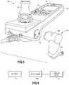
- FIG. 5is a perspective view of a charger connector about to be connected to a charger port on the hand control
- FIG. 6is a diagram illustrating components of the personal mobility vehicle
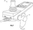
- FIG. 7is a perspective view similar to FIG. 5 showing the charger connector after being connected to a charger port on the hand control;
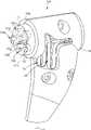
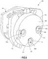
- FIG. 8is a perspective view showing the charger port shown in FIG. 5 ;
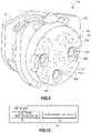
- FIG. 9is a diagram illustrating the internal components of the charger port shown in FIG. 8 ;
- FIG. 10is a diagram illustrating some of the components of the controller shown in FIG. 6 ;
- FIG. 11is a perspective view of the charger connector shown in FIGS. 5 and 7 ;
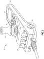
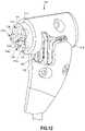
- FIG. 12is a diagram illustrating the internal components of the charger connector shown in FIG. 11 ;
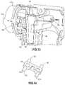
- FIG. 13is a diagram illustrating some of the internal components of the charger connector shown in FIG. 12 ;
- FIG. 14is a perspective view of one of the components shown in FIG. 13 .
- FIG. 1there is shown a perspective view of a personal mobility vehicle 10 incorporating features of an example embodiment.
- a personal mobility vehicle 10incorporating features of an example embodiment.
- the inventionwill be described with reference to the exemplary embodiments shown in the drawings, it should be understood that the invention can be embodied in many alternate forms of embodiments.
- any suitable size, shape or type of elements or materialscould be used.
- the personal mobility vehicleis embodied as a wheelchair system 10 , although this is not a limitation upon the use and practice of the exemplary embodiments of this invention.
- a wheelchair systemis considered as a vehicle that may be capable of controlled, self-powered (e.g., battery powered) movement for a sitting person.
- the wheelchair system 10includes a seat portion 12 , a power source 14 , such as a battery and related power conversion, conditioning and recharging circuitry, and at least two wheels 16 that are driven by the power source 14 via at least one motor 14 A.
- a power source 14such as a battery and related power conversion, conditioning and recharging circuitry
- At least two wheels 16that are driven by the power source 14 via at least one motor 14 A.
- One or more other wheels 18provide stability and enable steering of the wheelchair system 10 .
- a user-actuated hand control system (or user interface) 20.
- An attendant control system 22may also be provided.
- the control system 20operates with a control system of controller (or control unit) 24 to provide functions that include, but need not be limited to, starting and stopping motive power to the drive wheels 16 , controlling the direction of rotation and speed of rotation of the drive wheels 16 , and controlling a pointing direction of the wheels 18 to provide steering of the wheelchair 10 .
- FIG. 2shows a simplified block diagram of a portion of the controller 24 .
- the controller 24can be assumed to include a software system 28 that includes at least one data processor 28 A, such as a microprocessor or microcontroller, and a memory 28 B that stores programs to control operation of the data processor 28 A and, thereby, to control the overall operation of the wheelchair 10 .
- the operating programsalso referred to as system control software (SW) 29 A, may include firmware, such as computer programs that are permanently stored in, by example, non-volatile flash memory, or system control SW 29 A may be stored in volatile random access memory (RAM) 29 B that is loaded from an SD card or flash type of memory storage medium.
- RAMvolatile random access memory
- the exemplary embodiments of this inventionare also usable with a system where a system control SW 29 A is stored in a mass memory device, such as SD card(s) and/or flash memory(ies), and loaded into RAM as needed.
- the data processor 28 Ais coupled via general use input/output hardware 26 to various input/outputs, including general input/outputs, such as input/outputs 24 A going to and from the user-actuated hand control system 20 and inputs/outputs 24 B providing control to the motor(s) 14 .
- a clock function or module 28 Ccan be included for maintaining an accurate time of day and calendar function.
- the controller 24can further be connected to a wireless interface (WI) 30 , such as a BluetoothTM interface, for example.
- WIwireless interface
- any suitable type of wireless interface or connectionmay be provided.
- the user-actuated hand control system (or user interface) 20includes a housing 32 , a joystick type controller 34 , a first keypad 36 , a second keypad 38 , a charger port 39 , and a display 40 , such as an LCD, LED or other suitable type of display system.
- the first keypad 36is located in front of the joystick 34 (and between the joystick 34 and the display 40 ).
- the second keypad 38is located behind (or on the rear side of) the joystick 34 .
- Each of the keys on the keypad 36 , 38may comprise any suitable type of key such as press keys, toggle keys, touch, virtual/soft keys, etc.
- the charger port 39is configured to have a battery charger connected thereto to allow recharging of the battery 14 .
- the user-actuated hand control system 20generally allows the user to control the various functions of the wheelchair.
- the user-actuated hand control system 20operates with the control system of the controller 24 or a seat or auxiliary module (or auxiliary seating module) 25 to provide functions that include, but need not be limited to, starting and stopping motive power to the drive wheels 16 , controlling the direction of rotation and speed of rotation of the drive wheels 16 , controlling a pointing direction of the wheels 18 to provide steering of the wheelchair 10 , controlling a seat function, and controlling auxiliary functions.
- the user-actuated hand control system 20may be directly connected to the controller 24 (such as by a cable, for example).
- the user-actuated hand control system 20provides improvements over single keypad conventional configurations by allowing for operation of the personal mobility vehicle 10 with user input from a keypad in front of the joystick, and/or for operation of the personal mobility vehicle 10 with user input from a keypad behind the joystick.
- Various exemplary embodiments of the inventionprovide a solution which allows the handcontrol to be fully adjustable with regard to usability, based on the current need of a user.
- the keys on the rear side of the joystickcan be freely configured for every possible function the wheelchair offers and suits the user.
- these keyswould be configured for easy/fast access of functions (e.g. seat functions).
- the keys on the rear side of the joystickcan be freely configured to access all available functions, to the extent of obviating the need for the front keypad.
- the keys from the keypad on the rear sideare freely configurable, the actual functions they contain will be displayed on an area of the display. Furthermore, for the keys on the rear side, there may be more than one set of functions for the keys. If there is more than one set of functions, the set of functions can be chosen by operating one of the keys as a ‘master’ (e.g. the leftmost or the rightmost keys).
- the keys in front of the joystickalso are freely configurable as well. This provides for the capability that the functionality of each key on each keypad 36 , 38 can be configured.
- key 42 of the second keypad 38corresponds to a first area 50 of the display 40 and shows that there is more than just one set of functions.
- the active set of functionscan be chosen by operating this key 42 .
- Key 44 of the second keypad 38corresponds to a second area 52 of the display 40 and based on the currently chosen function set, key 44 shows a function for “leg adjustment”.
- Key 46 of the second keypad 38corresponds to a third area 54 of the display 40 and based on the currently chosen function set, key 46 shows a function for “seat elevate”.
- Key 48 of the second keypad 38corresponds to a fourth area 56 of the display 40 and based on the currently chosen function set, key 48 shows a function for “backrest adjustment”. In some other alternative embodiments, there may be just one set of functions for the keys. In this case, key 42 would have a certain, singular function, however any suitable configuration may be provided.
- any one or more of the exemplary embodimentsprovide a dual configurable keypad configuration providing for the functionality of each key on each keypad 36 , 38 to be configurable by the user. This provides for greater usability (based on the current needs of the user) when compared to conventional configurations.
- Many of the conventional power wheel chair handcontrolsare typically comprised of a joystick, a display, and a single keypad (on only a single side of the display).
- Some users of personal mobility vehiclesprefer having the keypad in front of the joystick. Typically, these keys are used for functions that are enabled while the wheel chair is in drive mode. There are other users who have great difficulty operating keys located in front of the joystick due to the level of their disability. For these users, operating keys on the rear side of the joystick is preferred and advantageous. It is also possible that a user may be initially comfortable using the keys in the front of the joystick but as the disability progresses the keys in the back of the joystick are preferred. Thus technical effects of any one or more of the exemplary embodiments provide users (with varying degrees of disability) of the personal mobility vehicle with wheelchair input devices, such as the handcontrol 20 , that are configurable to match their needs.
- components of the inventioncan be operationally coupled or connected and that any number or combination of intervening elements can exist (including no intervening elements).
- the connectionscan be direct or indirect and additionally there can merely be a functional relationship between components.
- a personal mobility vehicle hand controlcomprises: a housing; a display proximate an end of the housing; a first keypad proximate the display; a second keypad proximate an opposite end of the housing; and a joystick between the first keypad and the second keypad; wherein at least one key of the first keypad is configurable to correspond with a function displayed on the display, and wherein at least one key of the second keypad is configurable to correspond with the same function displayed on the display
- a personal mobility vehiclecomprising: a controller having a data processor; and a personal mobility vehicle hand control as above, wherein the personal mobility vehicle hand control is connected to the controller.
- a personal mobility vehiclecomprises: a control unit having at least one data processor; and a personal mobility vehicle hand control connected to the control unit, wherein the personal mobility vehicle hand control comprises a housing, a display proximate an end of the housing, a first keypad proximate the display, a second keypad proximate an opposite end of the housing, and a joystick between the first keypad and the second keypad, wherein at least one key of the first keypad is configurable to correspond with a function displayed on the display, and wherein at least one key of the second keypad is configurable to correspond with the same function displayed on the display.
- a personal mobility vehicle as abovewherein the function corresponds to a leg adjustment feature, a seat elevation adjustment feature, or a backrest adjustment feature for a seat portion of the personal mobility vehicle.
- a personal mobility vehicle as abovewherein the second keypad is configured to be closer to a user of the personal mobility vehicle than the joystick, and wherein the first keypad is configured to be farther away from the user of the personal mobility vehicle than the joystick.
- a methodcomprises: providing a personal mobility vehicle hand control comprising a housing; providing a display proximate an end of the housing; providing a first keypad proximate the display; providing a second keypad proximate an opposite end of the housing; and providing a joystick between the first keypad and the second keypad; wherein at least one key of the first keypad is configurable to correspond with a function displayed on the display, and wherein at least one key of the second keypad is configurable to correspond with the same function displayed on the display.
- the functioncorresponds to a driving feature, a seat function feature, and/or an auxiliary function feature of the personal mobility vehicle.
- first keypad and the second keypadeach comprise press keys, toggle keys, touch, and/or virtual/soft keys.
- FIG. 5an alternate embodiment of a user interface 120 is shown. Similar to the user interface 20 shown in FIGS. 1 and 3 , the user interface 120 generally comprises a housing 132 , a joystick type controller 34 , a first keypad 36 , a display 40 , and a charger port 139 .
- FIG. 5shows one example of the charger port 139 and an example of the charger 140 .
- the charger 140has a first end with a plug 142 configured to be plugged into an electrical outlet, and a second end with a charger connector 144 .
- the charger connector 144is configured to be removably connected to the charger port 139 for recharging the battery 14 . As seen with reference to FIG.
- the vehiclemay have a controller 146 to control supply of electricity from the charger port 139 to the battery 14 .
- the controller 146may comprise the processor 28 A, the memory 28 B and the software stored on the memory 28 b .
- the controller in this examplealso comprises circuitry in the user input 120 including a printed circuit board in the user input 120 .
- the charger portis mounted into a sidewall of the input device 120 (handcontrol) and is a magnetic charger port configured to hold the charger connector magnetically thereagainst.
- the magnetic charger portmay be located at any suitable location on the wheelchair such as placed on any side of the wheelchair and is not limited to location on the side of the user input 120 .
- the magnetic charger connectormay be magnetically aligned, attracted and held in position with the magnetic charger port.
- spring actuated contactsmay be provided as a reliable electrical connection.
- the example mechanical designhelps to insure that an interruption detector (e.g.
- This signalmay control an electronic protection circuit, which is used to interrupt the charging current in order to avoid electrical arcing upon disconnection of the charging connector from the charging port. Additionally, the protection circuit may prevent leakage currents between the contact pins when the connector is not mated. An over-temperature switch-off may also be provided to prevent damage in case of foreseeable contamination or handling issues.
- the approachonly needs to be approximate because of magnets in the two devices.
- the connector 144gets magnetically attracted to the port 139 and, therefore, is positioned automatically to the port at a predetermined position on the port 139 .
- This magnetic attraction, alignment and holdingmakes connection of the connector 144 to the port much easier to accomplish than a conventional connector, and is particularly well suited for a user having physical disabilities.
- Disconnection of the connector 144 from the port 139merely requires overcoming the magnetic attraction of the magnets in the connector 144 to the port 139 without having to overcome frictional retention forces between the connector 144 and the port 139 .
- the charger port 139generally comprises a housing 150 , a first plurality of electrical contacts 152 , a first plurality of permanent magnets 154 , and a printed circuit board 156 .
- the charger port 139has three of the electrical contacts 152 in this example; two power contacts 152 a (a “+” and a “ ⁇ ”) and an interruption detector contact 152 b .
- the contacts 152have slightly concave front surfaces, and the front of the housing 150 is substantially flat at a connector mating face 158 .
- the connector mating face 158has three holes with slight tapered entrances 160 , and the front surfaces of the contacts 152 are slightly recessed inside the entrances.
- At least one of the contacts 152is electrically connected to the printed circuit board 156 .
- the controller 146may comprise an electronic protection circuit 162 and an over-temperature cutoff 164 . One or both of these may be provided on the printed circuit board 156 .
- the charger port 139has five of the permanent magnets 154 .
- First ones 154 a , 154 b , 154 c of the magnets 154have their magnetic poles orientated in a first direction and second ones 154 d , 154 e of the magnets 154 have their magnetic poles orientated in a second reverse direction.
- Thisprovides a polarization scheme to limit connection of the connector 144 to the port 139 to only one orientation/position.
- one of the magnets 154 bis located between the two power contacts 152 a
- the interruption detector contact 152 bis located between the second magnets 154 d , 154 e . This provides a compact spacing design.
- the charging connector 144generally comprises a second housing 170 , a second plurality of electrical contacts 172 , and a second plurality of magnets 174 .
- the second plurality of electrical contacts 172comprises two power contacts 172 a (a “+” and a “ ⁇ ”) and an interruption detector contact 172 b .
- the power contacts 172 aare movably mounted on the second housing 170 .
- FIGS. 11-12show the power contacts 172 a in their forward extended positions. However the power contacts 172 a are mounted to the housing 170 in order to be pushed rearward in a direction into the housing 170 .
- the interruption detector contact 172 bis stationarily attached to the housing 170 in this example. However, in an alternate example the interruption detector contact 172 b may also be movably mounted to the housing 170 .
- the front faces 173 of the contacts 172may be slightly convex to mate with the slightly concave shape of the front faces 151 of the contacts 152 . In an alternate example, the front faces 151 , 173 could merely be flat or have other shapes.
- the housing 170forms a handle for a user to locate the connector 144 towards the port 139 in order for the magnetic attraction forces in the port 139 and connector 144 to interact and pull the connector 144 against the port 139 .
- the housing 170has a mating connector flat front face 176 which is configured to abut against the flat face 158 of the port's housing 150 .
- the housing 170has projections 178 at opposite sides of the face 176 which are configured to project into the side slots 153 of the housing 150 . These projections 178 and slots 153 merely help to prevent accidental rotation of the connector 144 on the port 139 after connection.
- these projections 178 and slots 153may be sized and shaped to be able to function as cams or ramps; to help move the connector 144 away from port 139 during disconnection by rotating the connector 144 about the port 139 .
- the charging connector 144has five of the permanent magnets 172 . However, more or less than five permanent magnets could be provided. First ones 174 a , 174 b , 174 c of the magnets 174 have their magnetic poles orientated in a first direction and second ones 174 d , 174 e of the magnets 174 have their magnetic poles orientated in a second reverse direction. This provides a polarization scheme to limit connection of the connector 144 to the port 139 to only one orientation/position.
- one of the magnets 174 bis located between the two power contacts 172 a
- the interruption detector contact 172 bis located between the second magnets 174 d , 174 e .
- Thisprovides a compact spacing design.
- the first magnets 174 a - chave their polarity are orientated to attract with first magnets 154 a - c
- the second magnets 174 d - ehave their polarity orientated to attract with second magnets 154 d - e . This is illustrated by the North pole (N) and South pole (S) markings shown in the drawings.
- the two power contacts 172 aare attached to a frame piece 180 .
- the frame piece 180is located inside the housing 170 and is movable on the housing 170 , as indicated by arrow A, between a forward position and a rearward position.
- the frame piece 180might not be provide; such as where the two power contacts 172 a are configured to move separately relative to one another.
- the connector 144comprises two electrical conductors 182 which connect electrical wires (not shown) of the charger 140 to the power contacts 172 a .
- FIG. 13shows areas 184 for soldering the wires to the electrical conductors 182 . Areas 184 are at a first end of the electrical conductors 182 and areas 186 are at a second end of the electrical conductors 182 . The areas 186 contact the rear ends 188 of the power contacts 172 a . A center portion 190 of each of the electrical conductors 182 is fixedly held in the housing 170 .
- the electrical conductors 182each have a portion 192 which forms a deflectable spring to allow the areas 186 to bias the power contacts 172 a in a forward direction, but which allow the power contacts 172 a to move rearward with the portions 192 resiliently deflecting.
- FIG. 11shows the power contacts 172 a at their forward biased positions.
- the power contacts 172 awill make contact with the power contacts 152 a before the interruption detector contact 172 b makes contact with the interruption detector contact 152 b .
- Further movement of the charger connector 144 towards the charger port 139will cause the power contacts 172 a to be pushed inward into the housing 170 ; with the electrical conductors 182 resiliently deflecting at portions 192 .
- the controller 146is configured to maintain an open electrical circuit between the power contacts 152 a until the interruption detector contact 152 b makes contact with the interruption detector contact 172 b .
- the controller 146determines that the interruption detector contact 172 b has made contact with the interruption detector contact 152 b , the controller 146 will then enable the open circuit to be closed and electricity will then be able to flow through the charger 140 into the charger port 139 to thereby allow the battery 14 to begin recharging.
- the userIn order to disconnect the charger connector 144 from the charger port 139 , the user merely needs to pull on the charger connector 144 with sufficient force to overcome the magnetic attraction of the magnets 174 to the magnets 154 .
- the interruption detector contact 172 bwill disconnect from the interruption detector contact 152 b before the power contacts 172 a disconnect from the power contacts 152 a . This is provided by the biasing feature of the electrical conductors 182 against the power contacts 172 a to maintain electrical connection of the power contacts 172 a to the power contacts 152 a .
- the controller 146determines that the interruption detector contact 172 b has disconnected from the interruption detector contact 152 b , the controller will cause an open circuit to be created between the power contacts 152 a . This will prevent electrical arcing as the power contacts 172 a subsequently disconnect from the power contacts 152 a . Further pulling of the charger connector 144 away from the charger port 139 will cause the power contacts 172 a to eventually disconnect from the power contacts 152 a.
- a magnetic charger connectormay be used to provide a magnetic charger connector. Users with varying degrees of disability may require their wheelchair charger connection to be well accessible and easy to handle. This may be provided by mounting a magnetic charger port into the sidewalls of the input device (handcontrol). In alternate examples, the magnetic connector may be placed on any side of a Wheelchair device like handcontrol, advanced display or elsewhere. It may alternatively be placed as an independent charger device on any position/location of a wheelchair.
- the charger connectormay be magnetically aligned, attracted and held in position by the magnetic charger port.
- Spring actuated contactsmay be provided for a reliable electrical connection.
- the mechanical designmay be used to guarantee that an interruption detector (e.g. the inhibit contact) always releases first, before the power contacts, while unplugging the charger connector. This may be used to signal control of the electronic protection circuit, which interrupts the charging current in order to avoid electrical arcing upon disconnection. Additionally, the protection circuit may be used to prevent leakage currents between the contact pins when the connector is not mated.
- An over-temperature switch-off 164may be provided to prevent damage in case of foreseeable contamination or handling issues.
- the magnet charger port (MCP)may be integrated to the side of a wheel chair device.
- the usermerely has to approach with the magnet charger connector (MCC) to the MCP approximately. Then, the magnets will cause the MCC to be magnetically attracted towards the MCP and, therefore, positioned automatically to the MCC onto the MCP at a predetermined location with the electrical contacts being aligned.
- MCCmagnet charger connector
- an apparatuscomprising: a first electrical connector comprising a first housing, a first plurality of electrical contacts, and a first plurality of magnets; and a second electrical connector comprising a second housing, a second plurality of electrical contacts, and a second plurality of magnets, where the second plurality of electrical contacts comprise two power contacts and an interruption detector contact, where the power contacts are movably mounted on the second housing, where the first plurality of magnets is arranged on the first housing and the second plurality of magnets is arranged on the second housing to allow the second electrical connector to be mounted on the first electrical connector with the first plurality of magnets and the second plurality of magnets providing a magnetic holding force with each other and providing alignment of the second electrical connector with the first electrical connector to hold the second electrical connector against the first electrical connector at a predetermined position, where the first electrical connector has a first one of the first plurality of magnets with magnetic poles orientated opposite from magnetic poles of a second one of the first plurality of magnets,
- the power contacts of the second electrical connectormay be spring biased in a forward position on the second housing by electrical conductors in the second housing.
- the interruption detection contactmay be stationarily mounted on the second housing.
- the power contacts of the second electrical connectormay be connected to each other by a frame piece, where the frame piece is movable in the second housing between a forward position and a rearward position.
- the first plurality of magnetsmay comprise at least one magnet located between two electrical contacts of the first plurality of electrical contacts.
- the second plurality of magnetsmay comprise at least one magnet located between the two power contacts.
- the interruption detector contactmay be located between at least two magnets of the second plurality of magnets.
- the first plurality of magnetsmay comprise at least five magnets with at least two of the magnets having their poles orientated opposite to the magnetic poles of other ones of the at least five magnets.
- the first electrical connectormay comprise a printed circuit board connected to at least one of the first plurality of electrical contacts, where the printed circuit board comprises an electronic protection circuit and an over-temperature cutoff.
- the apparatusmay comprise a wheelchair having the first electrical connector thereon.
- the first electrical connectormay be on a side of a user control of the wheelchair, where the user control is configured to be used by a hand of a user while the user is on the wheelchair, and where the user control is configured to control movement of wheels of the wheelchair based upon electricity from a battery of a wheelchair.
- a personal mobility vehiclecomprising: a frame; wheels connected to the frame; a motor on the frame and connected to the wheels; a battery configured to supply electricity to the motor; a user control on the frame, where the user control is configured to be used by a hand of a user while the user is on the personal mobility vehicle, and where the user control is configured to control movement of the wheels based upon electricity from the battery; and a charger port on a side of the user control, where the charger port comprises: a first housing; a first plurality of electrical contacts; and a first plurality of magnets, where a first one of the first plurality of magnets comprises magnetic poles orientated opposite from magnetic poles of a second one of the first plurality of magnets, and where the first plurality of magnets are configured to allow a charger connector to be mounted on the charger port with the first plurality of magnets and a second plurality of magnets on the charger connector providing a magnetic holding force with each other and providing alignment of the charger connector with the charger
- the personal mobility vehiclemay further comprise a battery charging cord, where the battery charging cord comprises a first end having the charger connector and a second end having a plug configured to be plugged into an electrical outlet.
- the first plurality of magnetsmay comprise at least one magnet located between two electrical power contacts of the first plurality of electrical contacts.
- the charger connectormay comprise a second housing, a second plurality of electrical contacts, and a second plurality of magnets, where the second plurality of electrical contacts comprise two power contacts and an interruption detector contact, where the power contacts are movably mounted on the second housing, where the two power contacts of the second electrical connector are configured to disconnect from the first plurality of electrical contacts, when the second electrical connector is being disconnected from the first electrical connector, only after the interruption detector contact of the second plurality of electrical contacts disconnects from the first plurality of electrical contacts.
- the interruption detection contactmay be stationarily mounted on the second housing.
- the first plurality of magnetsmay comprise at least five magnets with at least two of the magnets having their poles orientated opposite to the magnetic poles of other ones of the at least five magnets.
- the charger portmay comprise a printed circuit board connected to at least one of the first plurality of electrical contacts, where the printed circuit board comprises an electronic protection circuit and an over-temperature cutoff.
- a charger connectormay be provided comprising: a housing; a plurality of electrical contacts on the housing; and a plurality of magnets on the housing, where the plurality of electrical contacts comprise two power contacts and an interruption detector contact, where the power contacts are movably mounted on the second housing, where the two power contacts are configured to disconnect from power electrical contacts of a charger port, when the charger connector is being disconnected from the charger port, only after the interruption detector contact disconnects from an electrical contact of the charger port, where the plurality of magnets comprise a first one of the plurality of magnets having magnetic poles orientated opposite from magnetic poles of a second one of the plurality of magnets, and where the plurality of magnets are configured to allow the charger connector to be mounted on the charger port with the plurality of magnets and a plurality of magnets on the charger port providing a magnetic holding force with each other and providing alignment of the charger connector with the charger port to hold the charger connector against the first electrical connector at a predetermined position.
Landscapes
- Engineering & Computer Science (AREA)
- Power Engineering (AREA)
- Transportation (AREA)
- Mechanical Engineering (AREA)
- Life Sciences & Earth Sciences (AREA)
- Sustainable Development (AREA)
- Sustainable Energy (AREA)
- Charge And Discharge Circuits For Batteries Or The Like (AREA)
- Electric Propulsion And Braking For Vehicles (AREA)
Abstract
Description
Claims (20)
Priority Applications (2)
| Application Number | Priority Date | Filing Date | Title |
|---|---|---|---|
| US16/559,782US11491884B2 (en) | 2017-01-19 | 2019-09-04 | Magnetic charger connector for wheelchair |
| US17/942,739US12083908B2 (en) | 2017-01-19 | 2022-09-12 | Magnetic charger connector for wheelchair |
Applications Claiming Priority (2)
| Application Number | Priority Date | Filing Date | Title |
|---|---|---|---|
| US15/409,737US10386936B2 (en) | 2017-01-19 | 2017-01-19 | Power wheelchair hand control with dual configurable keypads |
| US16/559,782US11491884B2 (en) | 2017-01-19 | 2019-09-04 | Magnetic charger connector for wheelchair |
Related Parent Applications (1)
| Application Number | Title | Priority Date | Filing Date |
|---|---|---|---|
| US15/409,737Continuation-In-PartUS10386936B2 (en) | 2017-01-19 | 2017-01-19 | Power wheelchair hand control with dual configurable keypads |
Related Child Applications (1)
| Application Number | Title | Priority Date | Filing Date |
|---|---|---|---|
| US17/942,739ContinuationUS12083908B2 (en) | 2017-01-19 | 2022-09-12 | Magnetic charger connector for wheelchair |
Publications (2)
| Publication Number | Publication Date |
|---|---|
| US20190389320A1 US20190389320A1 (en) | 2019-12-26 |
| US11491884B2true US11491884B2 (en) | 2022-11-08 |
Family
ID=68981429
Family Applications (2)
| Application Number | Title | Priority Date | Filing Date |
|---|---|---|---|
| US16/559,782Active2037-04-11US11491884B2 (en) | 2017-01-19 | 2019-09-04 | Magnetic charger connector for wheelchair |
| US17/942,739Active2037-07-16US12083908B2 (en) | 2017-01-19 | 2022-09-12 | Magnetic charger connector for wheelchair |
Family Applications After (1)
| Application Number | Title | Priority Date | Filing Date |
|---|---|---|---|
| US17/942,739Active2037-07-16US12083908B2 (en) | 2017-01-19 | 2022-09-12 | Magnetic charger connector for wheelchair |
Country Status (1)
| Country | Link |
|---|---|
| US (2) | US11491884B2 (en) |
Cited By (1)
| Publication number | Priority date | Publication date | Assignee | Title |
|---|---|---|---|---|
| US12083908B2 (en)* | 2017-01-19 | 2024-09-10 | Curtis Instruments, Inc. | Magnetic charger connector for wheelchair |
Families Citing this family (4)
| Publication number | Priority date | Publication date | Assignee | Title |
|---|---|---|---|---|
| US10974592B2 (en)* | 2017-10-23 | 2021-04-13 | Huffy Corporation | Power mechanism for automatically switching the operational mode of a child vehicle |
| DE202022103815U1 (en)* | 2021-07-14 | 2022-08-01 | Zf Friedrichshafen Ag | Connector interface, connector element, micro mobility vehicle |
| CN113725947B (en)* | 2021-07-26 | 2024-03-22 | 季华实验室 | Charging method of electric wheelchair, electric wheelchair and medium |
| CN217347941U (en)* | 2022-05-20 | 2022-09-02 | 宁海瑞贝特汽车用品有限公司 | Heating steering wheel cover |
Citations (117)
| Publication number | Priority date | Publication date | Assignee | Title |
|---|---|---|---|---|
| US4837547A (en)* | 1987-11-02 | 1989-06-06 | Therm-O-Disc, Incorporated | Thermal cutoff assembly |
| US4964805A (en)* | 1990-01-03 | 1990-10-23 | Amp Incorporated | Microcoxial connector having bipartite outer shell |
| US5349282A (en)* | 1990-12-11 | 1994-09-20 | Span, Inc. | Battery charging and monitoring system |
| US5476386A (en) | 1993-06-11 | 1995-12-19 | Booth; David R. | Base structure for an electrical relay |
| KR960006938Y1 (en) | 1993-09-22 | 1996-08-12 | 한일가전 주식회사 | Grounding device for magnetic plugs and plug receivers of electrical appliances |
| US5703324A (en)* | 1996-04-30 | 1997-12-30 | Fluke Corporation | Shielded banana plug with double shroud and input receptacle |
| US5725393A (en)* | 1996-09-23 | 1998-03-10 | S. C. Johnson & Son, Inc. | Electrical connector with variable plug retention mechanism |
| US5829987A (en) | 1995-04-01 | 1998-11-03 | Fritsch; Klaus-Dieter | Electromechanical connection device |
| US5909100A (en) | 1996-08-09 | 1999-06-01 | Sumitomo Wiring Systems, Ltd. | Charging connector for electric vehicle |
| US5921783A (en) | 1995-04-01 | 1999-07-13 | Klaus-Dieter Fritsch | Electromechanical connection device |
| US6231349B1 (en) | 1996-08-29 | 2001-05-15 | Achim Bullinger | Electromechanical connecting device |
| US6273736B1 (en)* | 1997-07-22 | 2001-08-14 | Applied Materials, Inc. | Safety guard for an RF connector |
| JP2002056929A (en) | 2000-08-11 | 2002-02-22 | Zojirushi Corp | Magnet plug |
| EP1220369A1 (en) | 2001-01-02 | 2002-07-03 | Furas S.A. | Safety connector for household table-top electrical appliances |
| US6623276B2 (en)* | 2001-01-02 | 2003-09-23 | Furas, S.A. | Safety connector for household table-top electrical appliances |
| US20040090209A1 (en)* | 2001-09-14 | 2004-05-13 | Junji Nishida | Charging circuit for secondary battery |
| KR20040074905A (en) | 2003-11-20 | 2004-08-26 | 임정희 | A set magnet plug |
| DE10333403A1 (en) | 2003-07-14 | 2004-09-23 | Albert Ackermann Gmbh & Co. Kg | Electrical lead cable plug-in connection system e.g. for nursing zone adjacent hospital bed, using magnetic force for preventing accidental release of plug-in connection |
| US20040209489A1 (en) | 2003-04-21 | 2004-10-21 | Clapper Edward O. | Apparatus for automatic docking |
| US6821126B2 (en) | 2000-12-14 | 2004-11-23 | Magcode Ag | Electromechanical connecting device |
| EP1152496B1 (en) | 2000-05-03 | 2005-09-07 | Volkswagen AG | Connection device |
| US20060110203A1 (en) | 2004-05-17 | 2006-05-25 | Grafton Charlene H | Dual numerical keyboard based on dominance |
| US20060294472A1 (en) | 2005-06-27 | 2006-12-28 | Compal Electronics, Inc. | User interface with figures mapping to the keys, for allowing a user to select and control a portable electronic device |
| US20070056780A1 (en)* | 2005-08-31 | 2007-03-15 | Invacare Corporation | Method and apparatus for setting or modifying programmable parameters in power driven wheelchair |
| US20070072443A1 (en)* | 2005-09-26 | 2007-03-29 | Apple Computer, Inc. | Magnetic connector for electronic device |
| DE202007012249U1 (en) | 2007-08-31 | 2007-10-25 | Seliger, Roland | Flexible source stone lamp |
| US20070254510A1 (en)* | 2006-04-27 | 2007-11-01 | Debey Henry C | Magnetically Retained Electrical Connector |
| US20070259536A1 (en)* | 2006-03-09 | 2007-11-08 | Rsga International, Inc. | Communication Connector |
| US7329128B1 (en)* | 2007-01-26 | 2008-02-12 | The General Electric Company | Cable connector |
| US7331793B2 (en) | 2005-12-16 | 2008-02-19 | Motorola, Inc. | Magnetic connector |
| US7344380B2 (en) | 2002-09-13 | 2008-03-18 | Magcode Ag | Method and device for producing an electrical connection of sub-assemblies and modules |
| US7351066B2 (en) | 2005-09-26 | 2008-04-01 | Apple Computer, Inc. | Electromagnetic connector for electronic device |
| US20080220324A1 (en)* | 2005-10-31 | 2008-09-11 | Phillips Steven J | Battery pack and internal component arrangement within the battery pack for cordless power tool system |
| US20080315846A1 (en)* | 2007-03-09 | 2008-12-25 | Sony Corporation | Battery pack, battery charger and charging method |
| FR2938383A1 (en) | 2008-09-16 | 2010-05-14 | Sebastien Philippe | Magnetic connector for connecting e.g. multimedia appliance and removable man machine interface, has connector part connected electrically and mechanically to another connector part by magnetic attraction of magnets or magnetic materials |
| US20100331081A1 (en)* | 2009-06-26 | 2010-12-30 | Curtis Instruments, Inc. | Integrated game function in a personal mobility vehicle, such as a wheelchair |
| US7931472B2 (en) | 2008-01-07 | 2011-04-26 | Arnon Haim David | Apparatus for transferring electric power from a mobile unit placed in various orientation on a stationary unit |
| US20110248670A1 (en)* | 2006-07-31 | 2011-10-13 | Kazuo Yamazaki | Charging power source apparatus |
| US20120143062A1 (en) | 2009-08-31 | 2012-06-07 | Koninklijke Philips Electronics N.V. | Magnetic diagnostic probe connector system |
| US20120146576A1 (en)* | 2010-06-11 | 2012-06-14 | Mojo Mobility, Inc. | System for wireless power transfer that supports interoperability, and multi-pole magnets for use therewith |
| US8241043B1 (en)* | 2011-04-01 | 2012-08-14 | Cheng Uei Precision Industry Co., Ltd. | Probe connector |
| DE202012007785U1 (en) | 2012-08-14 | 2012-09-17 | Rosenberger Hochfrequenztechnik Gmbh & Co. Kg | Plug connection for power transmission |
| CN102769228A (en) | 2012-08-09 | 2012-11-07 | 孙玉田 | Magnetic socket and plug |
| US8314669B2 (en) | 2008-10-14 | 2012-11-20 | Rosenberger Hochfrequenztechnik Gmbh & Co. Kg | Electromechanical connection system |
| US20120295451A1 (en) | 2011-05-20 | 2012-11-22 | Smart Power Solutions, Inc | Magnetic connecting device |
| EP2533374A1 (en) | 2011-06-06 | 2012-12-12 | novero GmbH | Connector assembly with a magnetic fixation |
| US8388354B1 (en) | 2011-12-01 | 2013-03-05 | Cheng Uei Precision Industry Co., Ltd. | Electrical connector |
| DE202013101011U1 (en) | 2013-03-08 | 2013-03-18 | Rosenberger Hochfrequenztechnik Gmbh & Co. Kg | Magnetic plug connection |
| US8398409B2 (en)* | 2008-08-12 | 2013-03-19 | Rosenberger Hochfrequenztechnik Gmbh & Co Kg | Apparatus for producing a connection |
| EP2595252A1 (en) | 2011-11-15 | 2013-05-22 | Schneider Electric Industries SAS | plug and socket assembly |
| US8465296B1 (en)* | 2012-02-21 | 2013-06-18 | Cheng Uei Precision Industry Co., Ltd. | Electrical connector |
| US20130175103A1 (en)* | 2011-03-03 | 2013-07-11 | Flowers IP LLC. | Moveable steering and universal charger |
| US8506314B2 (en) | 2009-03-13 | 2013-08-13 | Rosenberger Hochfrequenztechnik Gmbh & Co. Kg | Sealing of spring-loaded contact pin |
| US8529274B2 (en) | 2011-01-13 | 2013-09-10 | Hong Fu Jin Precision Industry (Shenzhen) Co., Ltd. | Electrical coupler |
| US20130286694A1 (en)* | 2012-04-26 | 2013-10-31 | Freescale Semiconductor, Inc | Power adapter and electrical connector therefor |
| CN203277811U (en) | 2013-03-25 | 2013-11-06 | 信音电子(中国)股份有限公司 | Magnetic type power connector |
| CN203277704U (en) | 2013-03-25 | 2013-11-06 | 信音电子(中国)股份有限公司 | Magnetic type power connector |
| CN203277810U (en) | 2013-03-25 | 2013-11-06 | 信音电子(中国)股份有限公司 | Magnetic type power connector |
| CN203277735U (en) | 2013-04-12 | 2013-11-06 | 信音电子(中国)股份有限公司 | Magnetic power supply connector |
| US8596881B2 (en) | 2010-12-09 | 2013-12-03 | Microsoft Corporation | Power and data connector |
| US20130335010A1 (en)* | 2012-06-19 | 2013-12-19 | Nuvoton Technology Corporation | Connector and control chip |
| US20140032952A1 (en)* | 2012-07-24 | 2014-01-30 | Samsung Electronics Co., Ltd. | Electronic apparatus and drive control method thereof |
| US20140055084A1 (en)* | 2012-08-21 | 2014-02-27 | Makita Corporation | Charger |
| US20140083225A1 (en)* | 2012-09-25 | 2014-03-27 | Penny & Giles Controls Limited | Control module for an electric wheelchair |
| US8696366B2 (en)* | 2012-04-03 | 2014-04-15 | Inhon International Co. Ltd. | Connector module having a male connector and a female connector each having a magnetic part, a cathode contact and an anode contact |
| US8734189B2 (en)* | 2011-10-12 | 2014-05-27 | Apple Inc. | Spring-loaded contact having dome-shaped piston |
| CN203690543U (en) | 2014-01-08 | 2014-07-02 | 信音电子(中国)股份有限公司 | Magnetic power source connector and electronic system using magnetic power source connector set |
| US8894419B1 (en)* | 2012-08-14 | 2014-11-25 | Bby Solutions, Inc. | Magnetically connected universal computer power adapter |
| CN203983568U (en) | 2014-06-13 | 2014-12-03 | 深圳市得润电子股份有限公司 | Arrangements of electric connection |
| US8970189B2 (en)* | 2011-08-11 | 2015-03-03 | Renesas Electronics Corporation | Voltage generation circuit |
| US9004924B2 (en)* | 2013-03-08 | 2015-04-14 | SINGATRON TECHNOLOGY (HongKong) CO., LIMITED | Magnetic power connector and an electronic system using the magnetic power connector assembly |
| US9004930B2 (en) | 2010-09-07 | 2015-04-14 | Schneider Electric Industries Sas | Electrical connector assembly |
| US9077105B2 (en) | 2011-04-27 | 2015-07-07 | Autoconnector Co., Ltd. | Structure of electromagnetic electrical connection device |
| US20150194764A1 (en) | 2012-07-31 | 2015-07-09 | Hewlett-Packard Development Company, L.P. | Magnetic connector for a computing device |
| US9083110B2 (en) | 2011-10-04 | 2015-07-14 | Todd Doobrow | Quick-disconnect power adapters |
| US9112303B2 (en)* | 2012-06-04 | 2015-08-18 | Adonit Co., Ltd. | Magnetic connector |
| US9130328B1 (en) | 2014-04-01 | 2015-09-08 | Insert Enterprise Co., Ltd. | RF pass-through connector |
| US20150263638A1 (en)* | 2014-03-11 | 2015-09-17 | Midastek Microelectronic Inc. | Smart power adaptor and method for controlling power supplay thereof |
| US9142912B1 (en)* | 2013-03-14 | 2015-09-22 | Lon W. Allen | Magnetic coupling systems |
| CN104966945A (en) | 2015-05-20 | 2015-10-07 | 郑州职业技术学院 | Novel electronic product charging interface |
| US9190782B2 (en) | 2012-04-30 | 2015-11-17 | Club Car, Llc | Power connection system |
| US20150364863A1 (en) | 2014-06-12 | 2015-12-17 | Heartware, Inc. | Percutaneous connector and associated methods of use |
| FR3012263B1 (en) | 2013-10-23 | 2015-12-18 | Schneider Electric Ind Sas | ASSEMBLY OF ELECTRICAL OUTLET |
| US20160013582A1 (en) | 2014-07-10 | 2016-01-14 | Norman R. Byrne | Electrical power coupling with magnetic connections |
| US9252531B2 (en)* | 2013-10-12 | 2016-02-02 | Foxconn Interconnect Technology Limited | Electrical connector with magnetic element |
| US20160062046A1 (en) | 2014-08-29 | 2016-03-03 | Hong Fu Jin Precision Industry (Shenzhen) Co., Ltd. | Connecting device and connecting device for robot manipulator |
| US9306323B2 (en) | 2012-11-26 | 2016-04-05 | Samsung Electronics Co., Ltd. | Cable connector device |
| US20160111871A1 (en)* | 2014-10-15 | 2016-04-21 | Schneider Electric USA, Inc. | Surge protection device having two part ceramic case for metal oxide varistor with isolated thermal cut off |
| US20160126665A1 (en)* | 2014-11-04 | 2016-05-05 | Yu-Cheng Yang | Magnetic electrical appliance connecting structure |
| US20160218461A1 (en) | 2013-09-06 | 2016-07-28 | Siemens Aktiengesellschaft | Subsea connection system |
| EP2667459B1 (en) | 2012-05-24 | 2016-08-10 | Schneider Electric Industries SAS | Set of electric connectors |
| US9419377B2 (en) | 2014-01-20 | 2016-08-16 | Foxconn Interconnect Technology Limited | Dual orientation electrical connector assembly |
| US9419376B1 (en) | 2014-04-17 | 2016-08-16 | Google Inc. | Multipurpose, electronically versatile connector for wearable electronics |
| US20160241016A1 (en)* | 2015-02-17 | 2016-08-18 | Fairchild Semiconductor Corporation | Adaptive overvoltage protection for adaptive power adapters |
| US9431182B2 (en) | 2014-01-17 | 2016-08-30 | Sps Inc. | Double contact point switch and a magnetic connector having the double contact point switch |
| US20160254616A1 (en) | 2013-11-08 | 2016-09-01 | Sps Inc. | Power supply system having magnetic connector |
| US20160308452A1 (en)* | 2015-04-17 | 2016-10-20 | Rohm Co., Ltd. | Bus controller |
| US20160336761A1 (en)* | 2015-05-14 | 2016-11-17 | Mediatek Inc. | Electronic device, charger within the electronic device, and detecting method for detecting abnormal status of connector of electronic device |
| US9509165B2 (en)* | 2011-10-25 | 2016-11-29 | Samsung Electronics Co., Ltd. | Apparatus and method for controlling charge current in portable terminal |
| US20160349814A1 (en)* | 2015-05-25 | 2016-12-01 | Active-Semi, Inc. | Adaptive USB Port Controller |
| WO2017001755A1 (en) | 2015-07-01 | 2017-01-05 | Gulplug | Electrical plug and socket assembly |
| WO2017020823A1 (en) | 2015-08-05 | 2017-02-09 | 尹东山 | Magnet weight-bearing connector |
| US9640921B2 (en)* | 2014-11-18 | 2017-05-02 | Samsung Electronics Co., Ltd | Electrical connector and electronic device including the same |
| US9660377B2 (en)* | 2012-03-19 | 2017-05-23 | Phitek Systems Limited | Connector apparatus |
| US9703271B2 (en) | 2014-07-01 | 2017-07-11 | Samsung Electronics Co., Ltd. | Wearable electronic device |
| US9711878B2 (en) | 2015-04-22 | 2017-07-18 | Foxconn Interconnect Technology Limited | Power connector having a strong contact |
| US9774137B2 (en) | 2015-12-30 | 2017-09-26 | Lg Electronics Inc. | Mobile terminal |
| US9806458B1 (en)* | 2016-10-21 | 2017-10-31 | Gt Contact Co., Ltd. | Electrically connecting device, electrical connector, and mating connector |
| US9865954B2 (en)* | 2014-02-20 | 2018-01-09 | Rosenberger Hochfrequenztechnik Gmbh & Co. Kg | Plug connection |
| US9893540B2 (en)* | 2014-01-28 | 2018-02-13 | Guangdong Oppo Mobile Telecommunications Corp., Ltd. | Power adapter, electronic device, and charging apparatus for electronic device |
| US9923358B2 (en)* | 2014-02-11 | 2018-03-20 | Fairchild Semiconductor Corporation | USB adapter protection |
| US10122116B2 (en)* | 2015-07-10 | 2018-11-06 | Gulplug | Electrical power-point assembly with electrical disconnection solution |
| US10333260B2 (en)* | 2016-08-31 | 2019-06-25 | Semiconductor Components Industries, Llc | High contact resistance detection |
| US10386936B2 (en)* | 2017-01-19 | 2019-08-20 | Curtis Instruments Inc. | Power wheelchair hand control with dual configurable keypads |
| US20190389320A1 (en)* | 2017-01-19 | 2019-12-26 | Curtis Instruments, Inc. | Magnetic Charger Connector for Wheelchair |
| US10523002B2 (en)* | 2016-12-05 | 2019-12-31 | Vanguard International Semiconductor Corporation | Electrostatic discharge protection circuit |
| US10547196B2 (en)* | 2015-10-07 | 2020-01-28 | Samsung Electronics Co., Ltd. | Electronic apparatus, charge controlling method, and computer-readable recording medium |
Family Cites Families (2)
| Publication number | Priority date | Publication date | Assignee | Title |
|---|---|---|---|---|
| US7252512B2 (en)* | 2004-04-21 | 2007-08-07 | Japan Aviation Electronics Industry, Limited | Self-alignment magnetic connector reduced in size |
| US20090278532A1 (en)* | 2005-09-02 | 2009-11-12 | Warren Gordon Pettigrew | Angular position sensing device |
- 2019
- 2019-09-04USUS16/559,782patent/US11491884B2/enactiveActive
- 2022
- 2022-09-12USUS17/942,739patent/US12083908B2/enactiveActive
Patent Citations (123)
| Publication number | Priority date | Publication date | Assignee | Title |
|---|---|---|---|---|
| US4837547A (en)* | 1987-11-02 | 1989-06-06 | Therm-O-Disc, Incorporated | Thermal cutoff assembly |
| US4964805A (en)* | 1990-01-03 | 1990-10-23 | Amp Incorporated | Microcoxial connector having bipartite outer shell |
| US5349282A (en)* | 1990-12-11 | 1994-09-20 | Span, Inc. | Battery charging and monitoring system |
| US5476386A (en) | 1993-06-11 | 1995-12-19 | Booth; David R. | Base structure for an electrical relay |
| KR960006938Y1 (en) | 1993-09-22 | 1996-08-12 | 한일가전 주식회사 | Grounding device for magnetic plugs and plug receivers of electrical appliances |
| US5921783A (en) | 1995-04-01 | 1999-07-13 | Klaus-Dieter Fritsch | Electromechanical connection device |
| US5829987A (en) | 1995-04-01 | 1998-11-03 | Fritsch; Klaus-Dieter | Electromechanical connection device |
| US5703324A (en)* | 1996-04-30 | 1997-12-30 | Fluke Corporation | Shielded banana plug with double shroud and input receptacle |
| US5909100A (en) | 1996-08-09 | 1999-06-01 | Sumitomo Wiring Systems, Ltd. | Charging connector for electric vehicle |
| US6231349B1 (en) | 1996-08-29 | 2001-05-15 | Achim Bullinger | Electromechanical connecting device |
| US5725393A (en)* | 1996-09-23 | 1998-03-10 | S. C. Johnson & Son, Inc. | Electrical connector with variable plug retention mechanism |
| US6273736B1 (en)* | 1997-07-22 | 2001-08-14 | Applied Materials, Inc. | Safety guard for an RF connector |
| EP1152496B1 (en) | 2000-05-03 | 2005-09-07 | Volkswagen AG | Connection device |
| JP2002056929A (en) | 2000-08-11 | 2002-02-22 | Zojirushi Corp | Magnet plug |
| US6821126B2 (en) | 2000-12-14 | 2004-11-23 | Magcode Ag | Electromechanical connecting device |
| EP1220369A1 (en) | 2001-01-02 | 2002-07-03 | Furas S.A. | Safety connector for household table-top electrical appliances |
| US6623276B2 (en)* | 2001-01-02 | 2003-09-23 | Furas, S.A. | Safety connector for household table-top electrical appliances |
| US20040090209A1 (en)* | 2001-09-14 | 2004-05-13 | Junji Nishida | Charging circuit for secondary battery |
| US7344380B2 (en) | 2002-09-13 | 2008-03-18 | Magcode Ag | Method and device for producing an electrical connection of sub-assemblies and modules |
| US20040209489A1 (en) | 2003-04-21 | 2004-10-21 | Clapper Edward O. | Apparatus for automatic docking |
| DE10333403A1 (en) | 2003-07-14 | 2004-09-23 | Albert Ackermann Gmbh & Co. Kg | Electrical lead cable plug-in connection system e.g. for nursing zone adjacent hospital bed, using magnetic force for preventing accidental release of plug-in connection |
| KR20040074905A (en) | 2003-11-20 | 2004-08-26 | 임정희 | A set magnet plug |
| US20060110203A1 (en) | 2004-05-17 | 2006-05-25 | Grafton Charlene H | Dual numerical keyboard based on dominance |
| US20060294472A1 (en) | 2005-06-27 | 2006-12-28 | Compal Electronics, Inc. | User interface with figures mapping to the keys, for allowing a user to select and control a portable electronic device |
| US20070056780A1 (en)* | 2005-08-31 | 2007-03-15 | Invacare Corporation | Method and apparatus for setting or modifying programmable parameters in power driven wheelchair |
| US7901216B2 (en)* | 2005-09-26 | 2011-03-08 | Apple Inc. | Magnetic connector for electronic device |
| US8497753B2 (en)* | 2005-09-26 | 2013-07-30 | Apple Inc. | Electromagnetic connector for electronic device |
| US7311526B2 (en) | 2005-09-26 | 2007-12-25 | Apple Inc. | Magnetic connector for electronic device |
| US20070072443A1 (en)* | 2005-09-26 | 2007-03-29 | Apple Computer, Inc. | Magnetic connector for electronic device |
| US7351066B2 (en) | 2005-09-26 | 2008-04-01 | Apple Computer, Inc. | Electromagnetic connector for electronic device |
| US20080220324A1 (en)* | 2005-10-31 | 2008-09-11 | Phillips Steven J | Battery pack and internal component arrangement within the battery pack for cordless power tool system |
| US7331793B2 (en) | 2005-12-16 | 2008-02-19 | Motorola, Inc. | Magnetic connector |
| US20070259536A1 (en)* | 2006-03-09 | 2007-11-08 | Rsga International, Inc. | Communication Connector |
| US20070254510A1 (en)* | 2006-04-27 | 2007-11-01 | Debey Henry C | Magnetically Retained Electrical Connector |
| US20110248670A1 (en)* | 2006-07-31 | 2011-10-13 | Kazuo Yamazaki | Charging power source apparatus |
| US7329128B1 (en)* | 2007-01-26 | 2008-02-12 | The General Electric Company | Cable connector |
| US20080315846A1 (en)* | 2007-03-09 | 2008-12-25 | Sony Corporation | Battery pack, battery charger and charging method |
| DE202007012249U1 (en) | 2007-08-31 | 2007-10-25 | Seliger, Roland | Flexible source stone lamp |
| US7931472B2 (en) | 2008-01-07 | 2011-04-26 | Arnon Haim David | Apparatus for transferring electric power from a mobile unit placed in various orientation on a stationary unit |
| US8398409B2 (en)* | 2008-08-12 | 2013-03-19 | Rosenberger Hochfrequenztechnik Gmbh & Co Kg | Apparatus for producing a connection |
| FR2938383A1 (en) | 2008-09-16 | 2010-05-14 | Sebastien Philippe | Magnetic connector for connecting e.g. multimedia appliance and removable man machine interface, has connector part connected electrically and mechanically to another connector part by magnetic attraction of magnets or magnetic materials |
| US8314669B2 (en) | 2008-10-14 | 2012-11-20 | Rosenberger Hochfrequenztechnik Gmbh & Co. Kg | Electromechanical connection system |
| US8506314B2 (en) | 2009-03-13 | 2013-08-13 | Rosenberger Hochfrequenztechnik Gmbh & Co. Kg | Sealing of spring-loaded contact pin |
| US20100331081A1 (en)* | 2009-06-26 | 2010-12-30 | Curtis Instruments, Inc. | Integrated game function in a personal mobility vehicle, such as a wheelchair |
| US20120143062A1 (en) | 2009-08-31 | 2012-06-07 | Koninklijke Philips Electronics N.V. | Magnetic diagnostic probe connector system |
| US9570842B2 (en)* | 2009-08-31 | 2017-02-14 | Koninklijke Philips N.V. | Magnetic diagnostic probe connector system |
| US20120146576A1 (en)* | 2010-06-11 | 2012-06-14 | Mojo Mobility, Inc. | System for wireless power transfer that supports interoperability, and multi-pole magnets for use therewith |
| US9004930B2 (en) | 2010-09-07 | 2015-04-14 | Schneider Electric Industries Sas | Electrical connector assembly |
| US8596881B2 (en) | 2010-12-09 | 2013-12-03 | Microsoft Corporation | Power and data connector |
| US8529274B2 (en) | 2011-01-13 | 2013-09-10 | Hong Fu Jin Precision Industry (Shenzhen) Co., Ltd. | Electrical coupler |
| US20130175103A1 (en)* | 2011-03-03 | 2013-07-11 | Flowers IP LLC. | Moveable steering and universal charger |
| US8241043B1 (en)* | 2011-04-01 | 2012-08-14 | Cheng Uei Precision Industry Co., Ltd. | Probe connector |
| US9077105B2 (en) | 2011-04-27 | 2015-07-07 | Autoconnector Co., Ltd. | Structure of electromagnetic electrical connection device |
| US20120295451A1 (en) | 2011-05-20 | 2012-11-22 | Smart Power Solutions, Inc | Magnetic connecting device |
| EP2533374A1 (en) | 2011-06-06 | 2012-12-12 | novero GmbH | Connector assembly with a magnetic fixation |
| US8970189B2 (en)* | 2011-08-11 | 2015-03-03 | Renesas Electronics Corporation | Voltage generation circuit |
| US9083110B2 (en) | 2011-10-04 | 2015-07-14 | Todd Doobrow | Quick-disconnect power adapters |
| US8734189B2 (en)* | 2011-10-12 | 2014-05-27 | Apple Inc. | Spring-loaded contact having dome-shaped piston |
| US9509165B2 (en)* | 2011-10-25 | 2016-11-29 | Samsung Electronics Co., Ltd. | Apparatus and method for controlling charge current in portable terminal |
| EP2595252A1 (en) | 2011-11-15 | 2013-05-22 | Schneider Electric Industries SAS | plug and socket assembly |
| US8388354B1 (en) | 2011-12-01 | 2013-03-05 | Cheng Uei Precision Industry Co., Ltd. | Electrical connector |
| US8465296B1 (en)* | 2012-02-21 | 2013-06-18 | Cheng Uei Precision Industry Co., Ltd. | Electrical connector |
| US9660377B2 (en)* | 2012-03-19 | 2017-05-23 | Phitek Systems Limited | Connector apparatus |
| US8696366B2 (en)* | 2012-04-03 | 2014-04-15 | Inhon International Co. Ltd. | Connector module having a male connector and a female connector each having a magnetic part, a cathode contact and an anode contact |
| US9152198B2 (en)* | 2012-04-26 | 2015-10-06 | Freescale Semiconductor, Inc. | Power adapter and electrical connector therefor |
| US20130286694A1 (en)* | 2012-04-26 | 2013-10-31 | Freescale Semiconductor, Inc | Power adapter and electrical connector therefor |
| US9190782B2 (en) | 2012-04-30 | 2015-11-17 | Club Car, Llc | Power connection system |
| EP2667459B1 (en) | 2012-05-24 | 2016-08-10 | Schneider Electric Industries SAS | Set of electric connectors |
| US9112303B2 (en)* | 2012-06-04 | 2015-08-18 | Adonit Co., Ltd. | Magnetic connector |
| US20130335010A1 (en)* | 2012-06-19 | 2013-12-19 | Nuvoton Technology Corporation | Connector and control chip |
| US20140032952A1 (en)* | 2012-07-24 | 2014-01-30 | Samsung Electronics Co., Ltd. | Electronic apparatus and drive control method thereof |
| US20150194764A1 (en) | 2012-07-31 | 2015-07-09 | Hewlett-Packard Development Company, L.P. | Magnetic connector for a computing device |
| CN102769228A (en) | 2012-08-09 | 2012-11-07 | 孙玉田 | Magnetic socket and plug |
| DE202012007785U1 (en) | 2012-08-14 | 2012-09-17 | Rosenberger Hochfrequenztechnik Gmbh & Co. Kg | Plug connection for power transmission |
| US8894419B1 (en)* | 2012-08-14 | 2014-11-25 | Bby Solutions, Inc. | Magnetically connected universal computer power adapter |
| US20140055084A1 (en)* | 2012-08-21 | 2014-02-27 | Makita Corporation | Charger |
| US20140083225A1 (en)* | 2012-09-25 | 2014-03-27 | Penny & Giles Controls Limited | Control module for an electric wheelchair |
| US9306323B2 (en) | 2012-11-26 | 2016-04-05 | Samsung Electronics Co., Ltd. | Cable connector device |
| DE202013101011U1 (en) | 2013-03-08 | 2013-03-18 | Rosenberger Hochfrequenztechnik Gmbh & Co. Kg | Magnetic plug connection |
| US9004924B2 (en)* | 2013-03-08 | 2015-04-14 | SINGATRON TECHNOLOGY (HongKong) CO., LIMITED | Magnetic power connector and an electronic system using the magnetic power connector assembly |
| US9142912B1 (en)* | 2013-03-14 | 2015-09-22 | Lon W. Allen | Magnetic coupling systems |
| CN203277810U (en) | 2013-03-25 | 2013-11-06 | 信音电子(中国)股份有限公司 | Magnetic type power connector |
| CN203277704U (en) | 2013-03-25 | 2013-11-06 | 信音电子(中国)股份有限公司 | Magnetic type power connector |
| CN203277811U (en) | 2013-03-25 | 2013-11-06 | 信音电子(中国)股份有限公司 | Magnetic type power connector |
| CN203277735U (en) | 2013-04-12 | 2013-11-06 | 信音电子(中国)股份有限公司 | Magnetic power supply connector |
| US20160218461A1 (en) | 2013-09-06 | 2016-07-28 | Siemens Aktiengesellschaft | Subsea connection system |
| US9252531B2 (en)* | 2013-10-12 | 2016-02-02 | Foxconn Interconnect Technology Limited | Electrical connector with magnetic element |
| FR3012263B1 (en) | 2013-10-23 | 2015-12-18 | Schneider Electric Ind Sas | ASSEMBLY OF ELECTRICAL OUTLET |
| US20160254616A1 (en) | 2013-11-08 | 2016-09-01 | Sps Inc. | Power supply system having magnetic connector |
| CN203690543U (en) | 2014-01-08 | 2014-07-02 | 信音电子(中国)股份有限公司 | Magnetic power source connector and electronic system using magnetic power source connector set |
| US9431182B2 (en) | 2014-01-17 | 2016-08-30 | Sps Inc. | Double contact point switch and a magnetic connector having the double contact point switch |
| US9419377B2 (en) | 2014-01-20 | 2016-08-16 | Foxconn Interconnect Technology Limited | Dual orientation electrical connector assembly |
| US9893540B2 (en)* | 2014-01-28 | 2018-02-13 | Guangdong Oppo Mobile Telecommunications Corp., Ltd. | Power adapter, electronic device, and charging apparatus for electronic device |
| US9923358B2 (en)* | 2014-02-11 | 2018-03-20 | Fairchild Semiconductor Corporation | USB adapter protection |
| US9865954B2 (en)* | 2014-02-20 | 2018-01-09 | Rosenberger Hochfrequenztechnik Gmbh & Co. Kg | Plug connection |
| US20150263638A1 (en)* | 2014-03-11 | 2015-09-17 | Midastek Microelectronic Inc. | Smart power adaptor and method for controlling power supplay thereof |
| US9130328B1 (en) | 2014-04-01 | 2015-09-08 | Insert Enterprise Co., Ltd. | RF pass-through connector |
| US9419376B1 (en) | 2014-04-17 | 2016-08-16 | Google Inc. | Multipurpose, electronically versatile connector for wearable electronics |
| US20150364863A1 (en) | 2014-06-12 | 2015-12-17 | Heartware, Inc. | Percutaneous connector and associated methods of use |
| CN203983568U (en) | 2014-06-13 | 2014-12-03 | 深圳市得润电子股份有限公司 | Arrangements of electric connection |
| US9703271B2 (en) | 2014-07-01 | 2017-07-11 | Samsung Electronics Co., Ltd. | Wearable electronic device |
| US20160013582A1 (en) | 2014-07-10 | 2016-01-14 | Norman R. Byrne | Electrical power coupling with magnetic connections |
| US20160062046A1 (en) | 2014-08-29 | 2016-03-03 | Hong Fu Jin Precision Industry (Shenzhen) Co., Ltd. | Connecting device and connecting device for robot manipulator |
| US20160111871A1 (en)* | 2014-10-15 | 2016-04-21 | Schneider Electric USA, Inc. | Surge protection device having two part ceramic case for metal oxide varistor with isolated thermal cut off |
| US20160126665A1 (en)* | 2014-11-04 | 2016-05-05 | Yu-Cheng Yang | Magnetic electrical appliance connecting structure |
| US9640921B2 (en)* | 2014-11-18 | 2017-05-02 | Samsung Electronics Co., Ltd | Electrical connector and electronic device including the same |
| US20160241016A1 (en)* | 2015-02-17 | 2016-08-18 | Fairchild Semiconductor Corporation | Adaptive overvoltage protection for adaptive power adapters |
| US20160308452A1 (en)* | 2015-04-17 | 2016-10-20 | Rohm Co., Ltd. | Bus controller |
| US9711878B2 (en) | 2015-04-22 | 2017-07-18 | Foxconn Interconnect Technology Limited | Power connector having a strong contact |
| US20160336761A1 (en)* | 2015-05-14 | 2016-11-17 | Mediatek Inc. | Electronic device, charger within the electronic device, and detecting method for detecting abnormal status of connector of electronic device |
| CN104966945A (en) | 2015-05-20 | 2015-10-07 | 郑州职业技术学院 | Novel electronic product charging interface |
| US20160349814A1 (en)* | 2015-05-25 | 2016-12-01 | Active-Semi, Inc. | Adaptive USB Port Controller |
| US20180191097A1 (en)* | 2015-07-01 | 2018-07-05 | Gulplug | Electrical plug and socket assembly |
| WO2017001755A1 (en) | 2015-07-01 | 2017-01-05 | Gulplug | Electrical plug and socket assembly |
| US10122116B2 (en)* | 2015-07-10 | 2018-11-06 | Gulplug | Electrical power-point assembly with electrical disconnection solution |
| WO2017020823A1 (en) | 2015-08-05 | 2017-02-09 | 尹东山 | Magnet weight-bearing connector |
| US10547196B2 (en)* | 2015-10-07 | 2020-01-28 | Samsung Electronics Co., Ltd. | Electronic apparatus, charge controlling method, and computer-readable recording medium |
| US9774137B2 (en) | 2015-12-30 | 2017-09-26 | Lg Electronics Inc. | Mobile terminal |
| US10333260B2 (en)* | 2016-08-31 | 2019-06-25 | Semiconductor Components Industries, Llc | High contact resistance detection |
| US9806458B1 (en)* | 2016-10-21 | 2017-10-31 | Gt Contact Co., Ltd. | Electrically connecting device, electrical connector, and mating connector |
| US10523002B2 (en)* | 2016-12-05 | 2019-12-31 | Vanguard International Semiconductor Corporation | Electrostatic discharge protection circuit |
| US10386936B2 (en)* | 2017-01-19 | 2019-08-20 | Curtis Instruments Inc. | Power wheelchair hand control with dual configurable keypads |
| US20190389320A1 (en)* | 2017-01-19 | 2019-12-26 | Curtis Instruments, Inc. | Magnetic Charger Connector for Wheelchair |
Non-Patent Citations (1)
| Title |
|---|
| "XKeys Joystick Controller. Pdf" published Mar. 18, 2015, downloadable from website https://web.archive.org/web/20150318052848/http://www.ergocanada.com:80/detailed_specification_pages/pi_engineering_xkeys_joystick_controller_46_key.html. |
Cited By (1)
| Publication number | Priority date | Publication date | Assignee | Title |
|---|---|---|---|---|
| US12083908B2 (en)* | 2017-01-19 | 2024-09-10 | Curtis Instruments, Inc. | Magnetic charger connector for wheelchair |
Also Published As
| Publication number | Publication date |
|---|---|
| US20190389320A1 (en) | 2019-12-26 |
| US12083908B2 (en) | 2024-09-10 |
| US20230001809A1 (en) | 2023-01-05 |
Similar Documents
| Publication | Publication Date | Title |
|---|---|---|
| US11491884B2 (en) | Magnetic charger connector for wheelchair | |
| US9312907B2 (en) | Computer apparatus for use by senior citizens | |
| US8894419B1 (en) | Magnetically connected universal computer power adapter | |
| CA2732200C (en) | Apparatus for producing a connection | |
| JP2007533285A (en) | Method and apparatus for displaying state of charge | |
| JP4685956B2 (en) | Input device charging system | |
| KR200482089Y1 (en) | Charging holder for portable terminal | |
| US20050134215A1 (en) | Charging system for electronic devices | |
| US20170264045A1 (en) | Docking devices and cable connectors for patient monitoring systems | |
| US20190267758A1 (en) | Electricity charging plug device, electricity charging connection device, electricity charging device and electric vehicle | |
| EP2941368A1 (en) | Magnetic device mount | |
| KR101950765B1 (en) | A wireless charging tray unit capable of multi-coupling and a wireless charging system including the same | |
| CN101714676A (en) | Charging unit | |
| EP2453277A1 (en) | Device with magnetically mating optical data connectors | |
| CN114261317B (en) | Sliding unit for vehicle | |
| US9172262B2 (en) | Charging device and charging system | |
| JP2024038445A5 (en) | ||
| PH12020552027A1 (en) | Magnetic connector | |
| CN113783057A (en) | Female seat of USB with strengthen connection structure | |
| ATE112102T1 (en) | ELECTRICAL DEVICE. | |
| TWM380526U (en) | Portable electronic device with a rotary signal transmission interface | |
| KR101727024B1 (en) | Connecting Equipment for Charger | |
| CN112018559A (en) | Electric connection assembly, electronic equipment and use method of electric connection assembly | |
| CN222871072U (en) | Automatic foaming injection system | |
| WO2024212970A1 (en) | Support, bearing member and seat assembly |
Legal Events
| Date | Code | Title | Description |
|---|---|---|---|
| FEPP | Fee payment procedure | Free format text:ENTITY STATUS SET TO UNDISCOUNTED (ORIGINAL EVENT CODE: BIG.); ENTITY STATUS OF PATENT OWNER: LARGE ENTITY | |
| STPP | Information on status: patent application and granting procedure in general | Free format text:APPLICATION DISPATCHED FROM PREEXAM, NOT YET DOCKETED | |
| AS | Assignment | Owner name:CURTIS INSTRUMENTS, INC., NEW YORK Free format text:ASSIGNMENT OF ASSIGNORS INTEREST;ASSIGNORS:STUCKI, THOMAS;KURZEN, THOMAS;ZURBRUGG, CHRISTOF;AND OTHERS;REEL/FRAME:050892/0818 Effective date:20191030 | |
| STPP | Information on status: patent application and granting procedure in general | Free format text:DOCKETED NEW CASE - READY FOR EXAMINATION | |
| STPP | Information on status: patent application and granting procedure in general | Free format text:NON FINAL ACTION MAILED | |
| STPP | Information on status: patent application and granting procedure in general | Free format text:RESPONSE TO NON-FINAL OFFICE ACTION ENTERED AND FORWARDED TO EXAMINER | |
| STPP | Information on status: patent application and granting procedure in general | Free format text:NOTICE OF ALLOWANCE MAILED -- APPLICATION RECEIVED IN OFFICE OF PUBLICATIONS | |
| STPP | Information on status: patent application and granting procedure in general | Free format text:PUBLICATIONS -- ISSUE FEE PAYMENT VERIFIED | |
| STCF | Information on status: patent grant | Free format text:PATENTED CASE | |
| STPP | Information on status: patent application and granting procedure in general | Free format text:PUBLICATIONS -- ISSUE FEE PAYMENT VERIFIED | |
| STPP | Information on status: patent application and granting procedure in general | Free format text:AWAITING TC RESP, ISSUE FEE PAYMENT VERIFIED | |
| STPP | Information on status: patent application and granting procedure in general | Free format text:RESPONSE TO NON-FINAL OFFICE ACTION ENTERED AND FORWARDED TO EXAMINER | |
| STPP | Information on status: patent application and granting procedure in general | Free format text:NON FINAL ACTION MAILED | |
| STPP | Information on status: patent application and granting procedure in general | Free format text:RESPONSE TO NON-FINAL OFFICE ACTION ENTERED AND FORWARDED TO EXAMINER | |
| STPP | Information on status: patent application and granting procedure in general | Free format text:FINAL REJECTION MAILED | |
| STPP | Information on status: patent application and granting procedure in general | Free format text:RESPONSE AFTER FINAL ACTION FORWARDED TO EXAMINER | |
| STPP | Information on status: patent application and granting procedure in general | Free format text:NOTICE OF ALLOWANCE MAILED -- APPLICATION RECEIVED IN OFFICE OF PUBLICATIONS | |
| STPP | Information on status: patent application and granting procedure in general | Free format text:AWAITING TC RESP., ISSUE FEE NOT PAID | |
| STPP | Information on status: patent application and granting procedure in general | Free format text:NOTICE OF ALLOWANCE MAILED -- APPLICATION RECEIVED IN OFFICE OF PUBLICATIONS | |
| STPP | Information on status: patent application and granting procedure in general | Free format text:PUBLICATIONS -- ISSUE FEE PAYMENT RECEIVED | |
| STPP | Information on status: patent application and granting procedure in general | Free format text:PUBLICATIONS -- ISSUE FEE PAYMENT VERIFIED | |
| STCF | Information on status: patent grant | Free format text:PATENTED CASE | |
| AS | Assignment | Owner name:BANK OF AMERICA, N.A, AS COLLATERAL AGENT, NORTH CAROLINA Free format text:PATENT SECURITY AGREEMENT (TERM);ASSIGNORS:CURTIS INSTRUMENTS, INC.;DISCOVERY ENERGY, LLC;HEILA TECHNOLOGIES, INC.;REEL/FRAME:067290/0853 Effective date:20240501 | |
| AS | Assignment | Owner name:BANK OF AMERICA, N.A., AS COLLATERAL AGENT, NORTH CAROLINA Free format text:PATENT SECURITY AGREEMENT (ABL);ASSIGNORS:CURTIS INSTRUMENTS, INC.;DISCOVERY ENERGY, LLC;HEILA TECHNOLOGIES, INC.;REEL/FRAME:067306/0903 Effective date:20240501 |