US11491832B2 - Towing systems and methods using magnetic field sensing - Google Patents
Towing systems and methods using magnetic field sensingDownload PDFInfo
- Publication number
- US11491832B2 US11491832B2US17/097,507US202017097507AUS11491832B2US 11491832 B2US11491832 B2US 11491832B2US 202017097507 AUS202017097507 AUS 202017097507AUS 11491832 B2US11491832 B2US 11491832B2
- Authority
- US
- United States
- Prior art keywords
- load sensor
- magnetic field
- pin
- force
- load
- Prior art date
- Legal status (The legal status is an assumption and is not a legal conclusion. Google has not performed a legal analysis and makes no representation as to the accuracy of the status listed.)
- Active, expires
Links
Images


Classifications
- B—PERFORMING OPERATIONS; TRANSPORTING
- B60—VEHICLES IN GENERAL
- B60D—VEHICLE CONNECTIONS
- B60D1/00—Traction couplings; Hitches; Draw-gear; Towing devices
- B60D1/24—Traction couplings; Hitches; Draw-gear; Towing devices characterised by arrangements for particular functions
- B60D1/248—Traction couplings; Hitches; Draw-gear; Towing devices characterised by arrangements for particular functions for measuring, indicating or displaying the weight
- B—PERFORMING OPERATIONS; TRANSPORTING
- B60—VEHICLES IN GENERAL
- B60D—VEHICLE CONNECTIONS
- B60D1/00—Traction couplings; Hitches; Draw-gear; Towing devices
- B60D1/01—Traction couplings or hitches characterised by their type
- B—PERFORMING OPERATIONS; TRANSPORTING
- B60—VEHICLES IN GENERAL
- B60D—VEHICLE CONNECTIONS
- B60D1/00—Traction couplings; Hitches; Draw-gear; Towing devices
- B60D1/01—Traction couplings or hitches characterised by their type
- B60D1/06—Ball-and-socket hitches, e.g. constructional details, auxiliary devices, their arrangement on the vehicle
- B—PERFORMING OPERATIONS; TRANSPORTING
- B60—VEHICLES IN GENERAL
- B60D—VEHICLE CONNECTIONS
- B60D1/00—Traction couplings; Hitches; Draw-gear; Towing devices
- B60D1/48—Traction couplings; Hitches; Draw-gear; Towing devices characterised by the mounting
- B60D1/485—Traction couplings; Hitches; Draw-gear; Towing devices characterised by the mounting mounted by means of transversal members attached to the frame of a vehicle
- B—PERFORMING OPERATIONS; TRANSPORTING
- B60—VEHICLES IN GENERAL
- B60D—VEHICLE CONNECTIONS
- B60D1/00—Traction couplings; Hitches; Draw-gear; Towing devices
- B60D1/58—Auxiliary devices
- B60D1/62—Auxiliary devices involving supply lines, electric circuits, or the like
- B—PERFORMING OPERATIONS; TRANSPORTING
- B60—VEHICLES IN GENERAL
- B60D—VEHICLE CONNECTIONS
- B60D1/00—Traction couplings; Hitches; Draw-gear; Towing devices
- B60D1/58—Auxiliary devices
- B60D1/62—Auxiliary devices involving supply lines, electric circuits, or the like
- B60D1/64—Couplings or joints therefor
- G—PHYSICS
- G01—MEASURING; TESTING
- G01L—MEASURING FORCE, STRESS, TORQUE, WORK, MECHANICAL POWER, MECHANICAL EFFICIENCY, OR FLUID PRESSURE
- G01L1/00—Measuring force or stress, in general
- G01L1/12—Measuring force or stress, in general by measuring variations in the magnetic properties of materials resulting from the application of stress
- G01L1/125—Measuring force or stress, in general by measuring variations in the magnetic properties of materials resulting from the application of stress by using magnetostrictive means
- G—PHYSICS
- G01—MEASURING; TESTING
- G01L—MEASURING FORCE, STRESS, TORQUE, WORK, MECHANICAL POWER, MECHANICAL EFFICIENCY, OR FLUID PRESSURE
- G01L1/00—Measuring force or stress, in general
- G01L1/26—Auxiliary measures taken, or devices used, in connection with the measurement of force, e.g. for preventing influence of transverse components of force, for preventing overload
Definitions
- the inventionis related in general to systems and methods involving the use of magnetic field sensors and magneto-elastic devices for measuring a load and outputting a signal indicative of a load force dynamically applied to an object.
- the inventionis also related to use of the force-sensing apparatus in connection with a vehicle-trailer hitch or tow coupling.
- the inventionis also related to methods for determining a direction and magnitude of the force vector on the hitch or a particular hitch component.
- Tow coupling devicesare popular accessories for owners of passenger automobiles (cars and trucks) who tow trailers. These coupling devices may be purchased and installed in a new automobile, or purchased in the aftermarket and installed by owners after acquiring an automobile.
- the automotive and tow hitch industriesclassify trailer hitches according to various criteria. In one aspect, hitches are classified in one of Class 1-5.
- Each class of hitchincludes associated real-world standards such as minimum force load requirements, including at least longitudinal tension, longitudinal compression, transverse thrust, vertical tension, and vertical compression.
- strain gaugesare used for sensing a force load on a hitch. Strain gauges, however, often require a structural weakening of the load-conducting elements. There is a need for load measurements without compromising the structural stability of the measuring device. This is especially true for tow couplings.
- a load weight gauge(measuring the tongue load of a tow coupling), a tow load weight shift alert, an unsafe trailer load distribution alert, a vehicle limit notification, an automated trailer brake control (closed loop), a low/flat trailer tire notification, a check trailer brake notification, a closed loop braking control, a vehicle shift control, an engine control, and a stability control.
- a trailer's tongue weightis transferred to the rear axle of the tow vehicle. This can weigh down the vehicle's back end and cause the front end to point upward, especially on vehicles that have a suspension designed for driving comfort.
- the vehicle's rear axlewill bear the weight of not only the trailer, but much of the tow vehicle's weight as well. What is more, the lessened weight on the vehicle's front axle can diminish the ability to steer, maintain traction, and use available power for stopping.
- the vehiclemay experience increased trailer sway, and the driver's view of the road ahead may be limited due to the upward angle of the vehicle.
- Electronic force sensing devicesthat rely on detecting an amount of deflection of a portion of the sensor body (as an indication of an applied force on the body) may be designed to ensure that the amount of deflection (deformation) is elastically reversable such that the body returns to its original configuration (or very close to its original configuration) after the applied force is removed.
- Thisis important in the case of elongated shaft-like magnetoelastic load sensor pins because, in operation, they are fixed on their ends but are allowed to flex in the middle where the force is applied. If the shaft-like member is not elastically deformable, the body may be structurally and permanently changed after repeated cycles of increasing and decreasing amounts of applied force.
- the outputs from the sensing components of the load sensor pinmay need to be constantly adjusted (zeroed) to account for drift as the body of the device permanently changes from its original state.
- Force sensing devicesmay also be designed to incorporate sensor components that are adapted to output a representative signal across a wide range of applied forces acting on the sensor body, including an overload situation in which an unexpectedly large force is applied. This may be needed to prevent damage to the force sensor itself and damage to the device that the sensor is being used to monitor, such as a safety component of a vehicle. Although using less robust sensor components is possible in conjunction with monitoring for a saturation signal (100% of sensor output) as a proxy to alert a user to a possible overload situation, it may be necessary in some applications to understand the actual extent of the overload situation.
- Force sensing devicesmay also be designed to account for overload situations (in which, as noted above, a large force is applied) by providing for a large operating range. However, they end up using only a fraction of that range. For instance, a sensor package designed for an expected applied force that is much less than the overload situation could, for example, use only a fraction of its sensing capacity, which is usually at a lower end of the range. By way of example, a sensor package designed to account for an overload of 12,000 lbs. may operate in a narrow 10-15% of that range; thus, up to 85-90% of the sensor performance goes unused under normal operating conditions.
- an improved magneto-elastic based sensor assemblyis provided to effectively measure stress and strain in systems having a portion, which is subject to a mechanic load.
- the inventionalso provides a method of determining a direction of a load vector acting on a magneto-elastic based sensor assembly.
- a tow hitch assemblyincludes a hitch tube, a first part, a second part, a receiver tube, and first and second load sensor pins 8 , 9 connecting the first and second parts.
- the hitch tubeis typically a longitudinally extending, round, oval, square, or other shape member for attaching to a vehicle, typically near the rear bumper of a passenger vehicle. Bolts or other fastening means may be used to attach the hitch tube to the vehicle.
- the first part of the tow hitch assemblymay be a bracket with two side flange portions having through-holes: first and second through-holes on one flange, and third and fourth through-holes on the other, such that the first and third through-holes are axially aligned with each other and the second and fourth through-holes are also axially aligned with each other.
- the second partmay include a receiver tube connected to a longitudinally extending middle adapter member that fits between the two flanges of the bracket when the hitch components are in an assembled state.
- the adaptermay be configured to include a front portion that would be positioned in front of the hitch tube, and a back portion that would be positioned in back of the hitch tube, the front and the back portions each having a through-hole axially aligned with the through-holes on the bracket when the first and second parts are in an assembled state.
- the entirety of the adaptercould be in front of the hitch tube, or behind the hitch tube, or in some other configuration.
- first and second load sensor pins 8 , 9are configured to sense forces applied to the receiver tube and other components of the hitch assembly.
- One of the two load sensor pins 8 , 9extends through the first and third through-holes of the bracket and one of the through-holes of the adapter, and the other pin extends through the second and fourth through-holes of the bracket and a different through-hole of the adapter to secure the first and second parts together.
- the thickness of the base portion of the bracketis about 10 mm, and the gap is about 5 mm between the top of the middle adapter member and the base portion of the bracket.
- Press-fit bushingscould be used, having a pre-determined radial thickness inserted into the axially-aligned through-holes of the bracket.
- a forceis applied to the proximate end of a drawbar and transmitted to the front pin.
- the output signals from magnetic field sensors associated with the front pinmay be received in a suitable software algorithm, for example one that is embedded on a circuit board having a suitable processor located inside the front pin.
- the received output signals from the sensorswhich may be indicative of the magnetic field/flux exhibited by the front pin magneto-elastic active regions, may be used to determine the forces.
- a magneto-elastic sensorhaving a longitudinally extending shaft like member with at least one magneto-elastically active region and a magnetic field sensor device is described.
- the longitudinally extending shaft like memberis subject to a load introducing mechanic stress in the member.
- the at least one magneto-elastically active regionis directly or indirectly attached to the shaft like member.
- the at least one magneto-elastically active regionmay also form a part of the member.
- the magneto-elastically active regionis arranged in such a manner that the mechanic stress is transmitted to the active region.
- the regionincludes at least one magnetically polarized region such that the magnetic polarization becomes increasingly helically shaped as the applied stress increases.
- the magnetic field sensor means or deviceis arranged proximate to at least one magneto-elastically active region.
- the magnetic field sensor means/deviceis further configured for outputting a signal corresponding to a stress-induced magnetic flux, which emanates from the magnetically polarized region.
- the sensormay be a magnetic sensor device with at least one direction sensitive magnetic field sensor. This direction sensitive magnetic field sensor is configured for determination of a shear stress and/or of a tensile or compressive stress.
- the direction sensitive magnetic field sensoris arranged to have a predetermined and fixed spatial coordination with the member.
- One object of the invention described hereinwhich is also described in EP17162429.9, owned by Methode Electronics and incorporated herein by reference in its entirety, is a sensor assembly for force sensing, the force sensor being associated with a vehicle hitch assembly.
- the improved magneto-elastic based sensor assemblyis useful for effectively measuring stress and strain in systems having a portion, which is subject to a mechanic load.
- the inventionprovides a method of determining a direction of a load vector acting on a magneto-elastic based sensor assembly.
- a sensor assembly for force sensingcan include a first portion having a first and a second through-hole.
- the sensor assemblycan further include a second portion having a third and a fourth through-hole.
- the third and the fourth through-holecan be positioned in correspondence to the first and the second through-holes.
- the sensor assemblycan further include a first pin and a second pin.
- the first pincan be arranged such that it extends through the first and the third through-hole and the second pin can be arranged such that it extends through the second and the fourth through-hole, to couple the first portion to the second portion.
- At least one out of the first and the second pincan include at least one magneto-elastically active region that may directly or indirectly be attached to or form a part of the pin in such a manner that mechanic stress on the pin is transmitted to the magneto-elastically active region.
- the magneto-elastically active regioncan include at least one magnetically polarized region such that a polarization of the magnetically polarized region may become increasingly helically shaped as the applied stress increases.
- the sensor assemblycan further include a magnetic field sensor means or device which may be arranged proximate the at least one magneto-elastically active region.
- the magnetic field sensor means/devicemay be configured to output a signal corresponding to a stress-induced magnetic flux which may emanate from the magnetically polarized region.
- the magnetic field sensor means/devicemay comprise at least one direction sensitive magnetic field sensor which may be configured to determine a shear force in at least one direction.
- the at least one direction sensitive magnetic field sensormay in particular be arranged to have a predetermined and fixed spatial coordination with the pin, wherein this pin may at least be partially hollow.
- the at least one direction sensitive magnetic field sensormay be arranged inside an interior of this pin.
- the sensor assemblyBy means of the sensor assembly, stress which is applied to a pin caused by a mechanic load can effectively be measured.
- the sensor assembly according to aspects of the inventionthus described overcomes the drawback of the prior art solutions. In particular, the sensor assembly does not tend to drift with respect to the measurement values and is less error-prone.
- At least one out of the first and the second pin of the sensor assemblycan comprise at least one X-direction sensitive magnetic field sensor, which can be configured to detect a force component Fx 1 in a longitudinal direction X, and/or at least one Z-direction sensitive magnetic field sensor, which can be configured to detect a force component Fz 1 in a vertical direction Z.
- the longitudinal direction Xcan be defined by a direction of longitudinal extension of the second portion.
- the vertical direction Zcan be substantially perpendicular to the longitudinal direction X and substantially perpendicular to the transversal direction Y of longitudinal extension of the at least one pin.
- the first through-hole and the third through-hole of the sensor assemblycan be configured such that they encompass the first pin in a positive-fitting manner.
- a positive-fitting manner of the fittingallows the pin to be substantially rigidly fixed to the first portion and the second portion by the first and the third through-hole. This means that the pin has almost no play inside the first and third through-hole and that the accuracy of the force measurement is advantageously increased compared to a configuration in which the first pin has play inside the first and the third through-hole.
- the first pinmay be cryogenically treated, such as by subjecting the entire first pin to liquefied nitrogen, thereby causing a reduction in the cross-section dimension of the pin. After super-cooling the first pin, it may be positioned in the first and third through-holes and allowed to return to ambient temperature. As the material in the pin warms up to ambient temperature, the cross-section dimension will increase until the first pin is substantially rigidly fixed in the first and third through-holes.
- the second pin of the sensor assemblymay be encompassed by the second through-hole in a positive-fitting manner and the fourth through-hole may be configured such that the second pin may have one additional degree of freedom of movement within the fourth through-hole.
- the additional degree of freedom of movementallows the second pin to be insensitive with respect to shear forces acting in the direction of the additional degree of freedom of movement. This means that the determination of the shear force along this direction can advantageously be simplified since the shear effect occurs exclusively on the first pin.
- the second pinmay be cryogenically treated, such as by subjecting the entire first pin to liquefied nitrogen, thereby causing a reduction in the cross-section dimension of the pin. After super-cooling the second pin, it may be positioned in the second and fourth through-holes and allowed to return to ambient temperature. As the material in the second pin warms up to ambient temperature, the cross-section dimension will increase until the second pin is substantially rigidly fixed in the second and fourth through-holes with the additional degree of freedom of movement noted above.
- the additional degree of freedom of movementmay extend in the longitudinal direction X. Since the additional degree of freedom of movement corresponds to the longitudinal direction X, the determination of the shear force along this direction can advantageously be simplified.
- the first and/or the second pin of the sensor assemblycan include a first magneto-elastically active region and a second magneto-elastically active region.
- the first and the second magneto-elastically active regionsmay be directly or indirectly attached to or form parts of the pin in such a manner that mechanic stress may be transmitted to the magneto-elastically active regions.
- Each magneto-elastically active regioncan include a magnetically polarized region.
- the magnetic polarization of the first magneto-elastically active region and the magnetic polarization of the second magneto-elastically active regionmay be substantially opposite to each other.
- the magnetic field sensor means/devicecan include at least one first direction sensitive magnetic field sensor which may be arranged approximate the first magneto-elastically active region.
- the magnetic field sensor means/devicemay be configured to output a first signal corresponding to a stress-induced magnetic flux which may emanate from the first magneto-elastically active region.
- the magnetic field sensor means/devicemay include at least one second direction sensitive magnetic field sensor which may be arranged approximate the second magneto-elastically active region.
- the magnetic field sensor means/devicemay be configured to output a second signal corresponding to a stress-induced magnetic flux which may emanate from the second magneto-elastically active region.
- the differential evaluation of the signalsadvantageously doubles the signal, which is correlated with the applied stress. Because the polarization of the first and second magneto-elastically active region is opposite to each other, theoretically possible external fields may be compensated.
- the sensor assembly according to this embodimentmay be more sensitive and less susceptible to errors.
- the first and/or the second pin of the sensor assemblycan include at least one first X-direction sensitive magnetic field sensor and/or at least one second X-direction sensitive magnetic field sensor and/or at least one Z-direction sensitive magnetic field sensor and/or at least one second Z-direction sensitive magnetic field sensor.
- the at least one X-direction sensitive magnetic field sensormay be configured to detect a force component Fx 1 in the first magneto-elastically active region in the longitudinal direction X of the second portion.
- the at least one second X-direction sensitive magnetic field sensormay be configured to detect a force component Fx 2 in the second magneto-elastically active region in the longitudinal direction X of the second portion.
- the at least one Z-direction sensitive magnetic field sensormay be configured to detect a force component Fz 1 in the first magneto-elastically active region in the vertical direction Z.
- the at least one second Z-direction sensitive magnetic field sensormay be configured to detect a force component Fz 2 in the second magneto-elastically active region in the vertical direction Z.
- the shear forcecan be determined in different directions being perpendicularly aligned with respect to each other.
- the first pin of the sensor assemblycan include the at least one Z-direction sensitive magnetic field sensor and the at least one second Z-direction sensitive magnetic field sensor.
- the first pincan be configured to exclusively react on a shear force acting along the Z-direction.
- the first pin of the sensor assemblycan include the at least one first X-direction sensitive magnetic field sensor, the at least one second X-direction sensitive magnetic field sensor, the at least one first Z-direction sensitive magnetic field sensor and the at least one second Z-direction sensitive magnetic field sensor and the second pin of the sensor assembly can comprise the at least one Z-direction sensitive magnetic field sensor and the at least one second Z-direction magnetic field sensor.
- the first pincan be configured to exclusively react on the shear effect along the X-direction which simplifies the shear force evaluation, wherein the shear force along the vertical Z-direction is acting on both load sensor pins 8 , 9 .
- the first pin of the sensor assemblycan include the at least one first X-direction sensitive magnetic field sensor, the at least one second X-direction sensitive magnetic field sensor, the at least one first Z-direction sensitive magnetic field sensor and the at least one second Z-direction sensitive magnetic field sensor
- the second pin of the sensor assemblycan include the at least one first X-direction sensitive magnetic field sensor, the at least one second X-direction sensitive magnetic field sensor, the at least one first Z-direction sensitive magnetic field sensor and the at least one second Z-direction sensitive magnetic field sensor.
- the magnetic field sensor means/devicemay be configured for determination of a first component and a second component of the load, which is applied to the pin.
- the at least one first X-direction sensitive magnetic field sensor and the at least one second X-direction sensitive magnetic field sensorcan form a first group of sensors and the at least one first Z-direction sensitive magnetic field sensor and the at least one second Z-direction sensitive magnetic field sensor can form a second group of sensors.
- the first group of sensorsis suitable for determination of a load component, which is directed along the X-axis.
- the second group of sensorssenses a component of the load, which is substantially perpendicular to the first component along the Z-direction. Consequently, the direction and the value of the stress or force, which is applied to the load sensor pins 8 , 9 , may be determined from said components in this coordinate system.
- the second portion of the sensor assemblycan comprise a center wall which may extend in the longitudinal direction X and the vertical direction Z.
- the third and the fourth through-holemay also extend through the center wall.
- the center wallallows the first portion to be effectively affected by the shear force at an additional point of action.
- the first and/or the second pin of the sensor assemblymay be fixedly attached in a predetermined manner to the first portion.
- the first and/or the second pincan advantageously be fixedly attached in all six degrees of freedom. This way, the determination of the shear forces is effectively possible since the load sensor pins 8 , 9 do not have play inside the through-holes of the first portion.
- the first portion of the sensor assemblycan have a yoke-like shape.
- the yoke legs of the first portioncan comprise the first and the second through-holes.
- the second portion of the sensor assemblycan have a tubular shape.
- the side walls of the second portioncan comprise the third and fourth through-holes.
- the direction sensitive magnetic field sensor(s)may be configured to detect force components of shear forces introduced into the load sensor pins 8 , 9 by the first portion and the second portion.
- a yoke-like shape of the first portion and a tubular shape of the second portionallow the sensor assembly to be implemented in an elongated joint connection of two objects, whereas the load sensor pins 8 , 9 are arranged in the through-holes and connect both objects.
- the first portion of the sensor assemblycan have a yoke-like shape.
- the yoke legs of the first portioncan comprise the first and the second through-holes.
- the center wallcan comprise the third and fourth through-holes.
- the direction sensitive magnetic field sensor(s)may be configured to detect force components of shear forces introduced into the load sensor pins 8 , 9 by the first portion and the second portion.
- the side walls of the second portioncan comprise through-holes which may be larger than the third and the fourth through-holes such that the shear forces may be introduced into the load sensor load sensor pins 8 , 9 by abutment surfaces of the first and the second through-holes in the yoke legs and abutment surfaces of the third and the fourth through-holes in the center wall.
- the abutment surfacesallow the transmission of force between the first portion and the second portion to be configured in an advantageous manner.
- a tow couplingcan comprise a sensor assembly wherein the first portion is a hitch assembly that may be configured to be attached to a car chassis and wherein the second portion may be a receiving tube which may be configured to receive a drawbar, alternatively a hitch bar or a ball mount of the tow coupling.
- the sensor assemblyis configured to detect the forces of a tow coupling of an automobile, which may be part of a land based on-road or off-road vehicle.
- the first portion of the sensor assemblymay be a supporting yoke having two yoke legs.
- the yoke legsmay comprise recesses which are aligned in correspondence to each other and which represent the first and the second through-holes of the first portion.
- the first portion of the sensor assemblymay be a supporting yoke having four yoke legs.
- the yoke legsmay comprise recesses which are aligned in correspondence to each other and which represent the first and the second through-holes of the first portion.
- the sensor assemblydispenses with a mechanical linkage or connection between the magnetic field sensor means and the second portion. This eliminates sources of error, which result from mechanic failure of this connection.
- the sensor assemblyreliably operates even under extreme operating conditions. The drift of the measurement values during long term measurement is reduced.
- the sensor assembly according to aspects of the inventionis versatile in that it may be applied to or integrated in nearly every tubular shaped portion, which may be for example a part of a hydraulic unit of a land-, marine-, rail- or air transport vehicle.
- the forces which are detectable by the sensor assemblyare not exclusively restricted to shear forces which originate from shear stress but may also originate due to tensile or compressive stress acting on the magneto-elastically active region(s) of the first pin and/or the second pin of the sensor assembly.
- shear stress and normal stressmay both induce a variation of the polarization of the magnetically polarized region emanating from the magneto-elastically active region(s).
- This polarizationmay be detectable by the magnetic field sensor means which may output a signal corresponding to a stress-induced magnetic flux towards the polarization direction sensitive magnetic field sensor that may be configured to determine the acting force. Consequently, the magneto-elastically active region may be sensitive to all stress types.
- the embodimentmay particularly be suitable, if the pin is exposed to only one single type of stress.
- the direction sensitive magnetic field sensors Lmay be one of a Hall-effect, magneto-resistance, magneto-transistor, magneto-diode, MAGFET field sensors or fluxgate magnetometer.
- any hydraulic piston, crane application, car and other various applications incorporating bolts and load sensor pins 8 , 9 , where shear forces may be appliedmay be equipped with the sensor assembly according to aspects of the invention.
- shear force sensors using strain-gaugesare designed in that they get intentionally weaken to provide enough deformation so as to allow a measurement of the applied loads.
- the magneto-elastically active region of the sensor assemblyprovides the possibility to design the bolt without weaken locations and significantly higher overload capability.
- the load pin having the integrated magneto-elastically active regionprovides the possibility to detect shear forces in load sensor pins 8 , 9 , screws, bolts etc.
- a method of determining a direction of a load vectoris provided.
- a sensor assemblyaccording to aspects of the invention is provided.
- a sensor assemblywhich can comprise a first portion having a first and a second through-hole.
- the sensor assemblycan further comprise a second portion having a third and a fourth through-hole.
- the third and the fourth through-holecan be positioned in correspondence to the first and the second through-hole.
- the sensor assemblycan further comprise a first pin and a second pin.
- the first pincan be arranged such that it extends through the first and the third through-hole and the second pin can be arranged such that it extends through the second and the fourth through-hole, so as to couple the first portion to the second portion.
- At least one out of the first and the second pincan comprise at least one magneto-elastically active region that may directly or indirectly be attached to or form a part of the pin in such a manner that mechanic stress on the pin is transmitted to the magneto-elastically active region.
- the magneto-elastically active regioncan comprise at least one magnetically polarized region such that a polarization of the magnetically polarized region may become increasingly helically shaped as the applied stress increases.
- the sensor assemblycan further comprise a magnetic field sensor means which may be arranged approximate the at least one magneto-elastically active region.
- the magnetic field sensor meansmay be configured to output a signal corresponding to a stress-induced magnetic flux which may emanate from the magnetically polarized region.
- the magnetic field sensor meansmay comprise at least one direction sensitive magnetic field sensor which may be configured to determine a shear force in at least one direction.
- the at least one direction sensitive magnetic field sensormay in particular be arranged to have a predetermined and fixed spatial coordination with the pin, wherein this pin may at least be partially hollow.
- the at least one direction sensitive magnetic field sensormay be arranged inside an interior of this pin.
- the first pin and the second pinmay be exposed to a load.
- Measurement data of the at least one direction sensitive magnetic field sensormay be processed so as to determine a shear stress and/or a tensile or compressive stress that is applied by the second portion and the first portion to the first and/or second load sensor pins 8 , 9 .
- a direction of a force Fmay be determined from the measurement data on the one hand and the predetermined and known spatial coordination between the direction sensitive magnetic field sensor(s), the first pin, the second pin and the point of load.
- the force Fis applied to the sensor assembly via the second portion.
- a magneto-elastic torque sensorin which an output signal indicative of a force applied to a member is provided.
- the sensorincludes a first magneto-elastically active region in the member, the region being ferromagnetic, magnetostrictive magnetically polarized in a single circumferential direction and possessing sufficient magnetic anisotropy to return the magnetization in the region to the single circumferential direction when the applied torque is reduced to zero, whereby the ferromagnetic, magnetostrictive region produces a magnetic field varying with the torque.
- Magnetic field sensorsare mounted proximate to the ferromagnetic, magnetostrictive region to sense the magnetic field at the sensors and provide the output signal in response thereto.
- the deviceincludes an annular region of a plate is magnetized with a circumferential magnetization. Magnetic field sensors are then placed near this magnetized band at locations where the magnetization direction is non-parallel and non-perpendicular to the axis of tension. The strain-induced magnetic anisotropy caused by tension or compression then produces a shift in the magnetization direction in the plate regions near the field sensors, thereby causing magnetic field changes which are detected by the magnetic field sensors.
- the magnetic field sensorsare connected to an electronic circuit which outputs a voltage signal which indicates the tension or compression in the plate.
- an embedded software programis used to receive signals from various sensors and output a signal containing information useful in determining or assessing a load weight gauge (measuring the tongue load of a tow coupling), a tow load weight shift alert, an unsafe trailer load distribution alert, a vehicle limit notification, an automated trailer brake control (closed loop), a low/flat trailer tire notification, a check trailer brake notification, a closed loop braking control, a vehicle shift control, an engine control, and a stability control.
- shielding material or a shielding device or multiple shielding devicesmay be used to shield the load sensor pins 8 , 9 from the effects of external magnetic sources, such as nearby permanent magnets.
- a flux directormay be used to direct external magnetic fields to minimize or reduce their effect on the load sensor pins 8 , 9 and the output signal from the load sensor pins 8 , 9 .
- the load sensor pins 8 , 9output one or more signals to one or more microcontroller units.
- the microcontrollersare adapted to processing the signals and providing processed signals to a vehicle onboard control system via the vehicle's bus network.
- the processed signalmay include information related to a comparison of the load pin forces to one or more threshold forces and instructional data for corrective actions to be taken by one or more vehicle control systems in response thereto.
- the load sensor pins 8 , 9 and other components of the tow coupling apparatusmay be used to measure a sprung weight of a towing or towed vehicle by measuring the shear forces on the load sensor pins 8 , 9 caused by the weight on the vehicle producing a force on the load sensor pins 8 , 9 .
- the load sensor pins 8 , 9 and other components of the tow coupling apparatusmay be used in connection with a weight distribution-type tow hitch and algorithms utilizing individual load sensor pin output signals may be employed to assess a tongue load and other shear forces on a hitch caused by a trailer attached to a tow vehicle.
- the present inventionprovides additional advantageous features related to magneto-elastic sensors for measuring forces, especially loads applied to one or more components of a vehicle hitch assembly.
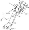
- FIG. 1Ais a simplified, schematic diagram of the outside of a load sensor pin for use with a tow coupling apparatus
- FIGS. 1B and 1Care simplified side and perspective views of the load sensor pins of FIG. 1A for use with a vehicle tow coupling apparatus;
- FIG. 1Dis simplified side view of the load sensor pins of FIG. 1A with press-fitted bushing
- FIG. 1Eis a perspective view of bushings used in connection with the load sensor pins.
- FIG. 2Ais a simplified, schematic diagram of the outside of another load sensor pin for use with a vehicle tow coupling apparatus
- FIGS. 2B and 2Care simplified side and perspective views of the load sensor pin of FIG. 2A for use with a vehicle tow coupling apparatus;
- FIG. 3is a simplified, perspective, exploded view diagram of some of the components of a “front” load sensor pin
- FIG. 4is a simplified perspective view schematic diagram of a multi-pin electrical connector for use with the load sensor pin of FIG. 3 ;
- FIG. 5is a simplified, cross-sectional, plan view diagram of the load sensor of FIG. 3 ;
- FIG. 6is a simplified, perspective exploded view diagram of some of the components of a “back” load sensor pin
- FIG. 7is a simplified, cross-sectional, plan view diagram of the load sensor of FIG. 6 ;
- FIG. 8is a simplified, partial, cross-sectional, plan view diagram of the load sensor of FIG. 6 ;
- FIG. 9is a simplified, partial, cross-sectional, plan view diagram of the “front” and “back” load sensor pins of FIGS. 3 and 6 and some of the components of a tow coupling apparatus;
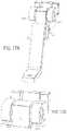
- FIG. 10Ais a simplified, cross-sectional view drawing of another aspect of a load sensor pin
- FIG. 10Bis a simplified, partial, cross-sectional, perspective view diagram of the load sensor pin of FIG. 10A ;
- FIG. 10Cis a simplified, partial, perspective view diagram of another aspect of a load sensor pin of FIG. 10A ;
- FIG. 10Dis a simplified, end view diagram of yet another aspect of the load sensor pin of FIG. 10A ;
- FIG. 11Ais a simplified, schematic diagram of the load sensor pin of FIG. 2A with a shielding device
- FIG. 11Bis a simplified, exploded, perspective view diagram of the components of a load sensor pin showing a printed circuit board between two elongated magnetic field shielding members;
- FIG. 12Ais a simplified, partial, perspective view diagram of some of the components of a load sensor pin having a secondary magnetic field sensor
- FIG. 12Bis another simplified, partial, perspective view diagram of some of the components of the load sensor pin of FIG. 12A ;
- FIG. 13is a simplified, partial, perspective view diagram of some of the components of a tow coupling apparatus showing front load sensor pin 8 and back load sensor pin 9 ;
- FIG. 14is another simplified, partial, perspective view diagram of the components of the tow coupling apparatus showing front load sensor pin 8 and back load sensor pin 9 ;
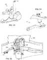
- FIG. 15is a simplified, partial, cross-sectional, end view diagram of the components of the tow coupling apparatus of FIG. 13 ;
- FIG. 16is another simplified, partial, cross-sectional, end view diagram of the components of the tow coupling apparatus of FIG. 13 ;
- FIG. 17Ais a simplified, partial, perspective view diagram of the tow coupling apparatus of FIG. 14 ;
- FIG. 17Bis a close-up simplified, partial, perspective view diagram of the apparatus of FIG. 14 ;
- FIG. 18Ais a simplified, partial, perspective view diagram of some of the components of the tow coupling apparatus of FIG. 14 showing a first load case;
- FIG. 18Bis another simplified, partial, perspective view diagram of some of the components of the tow coupling apparatus of FIG. 14 showing a different load case;
- FIG. 19Ais a simplified, partial, perspective view diagram of the vehicle tow coupling apparatus of FIG. 14 with a shielding device;
- FIG. 19Bis a semi-transparent diagram of FIG. 19A ;
- FIG. 19Cis another view of the shielding device of FIG. 19A ;
- FIG. 20Ais a simplified, side view diagram of the tow coupling apparatus of FIG. 14 showing another load case
- FIGS. 20B through 20Kare simplified, partial cross section, top or side view diagrams of alternative arrangements of a tow coupling apparatus
- FIG. 21is a simplified, side view diagram of a tow coupling apparatus and vehicle components
- FIGS. 22A through 22Eare simplified, partial, cross-sectional, and perspective view diagrams of a tow coupling apparatus including load sensor pins 8 , 9 ;
- FIGS. 23A through 23Care simplified, partial, cross-sectional, and perspective view diagrams of a tow coupling apparatus including load sensor pins 8 , 9 ;
- FIG. 24is a simplified, schematic, perspective view diagram of a tow coupling apparatus including a single load sensor pin 8 or 9 ;
- FIG. 25is another simplified, schematic, perspective view diagram of a tow coupling apparatus including a single load sensor pin 8 or 9 ;
- FIG. 26is a simplified, perspective view diagram of one component of a tow coupling apparatus showing upper and lower load sensor pins 8 , 9 ;
- FIG. 27is a simplified, perspective view diagram of the coupling components of a vehicle tow coupling apparatus
- FIG. 28is a simplified, perspective, exploded view diagram of some of the components of another tow coupling apparatus.
- FIG. 29Ais another simplified, perspective, exploded view diagram of the modified components of the tow coupling apparatus of FIG. 28 ;
- FIG. 29Bis a simplified, perspective view diagram of the components of the tow coupling apparatus of FIG. 28 ;
- FIG. 29Cis a simplified, perspective view diagram of another tow coupling apparatus.
- FIG. 29Dis a simplified, cross-sectional view diagram of the tow coupling apparatus of FIG. 29C ;
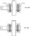
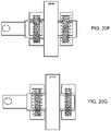
- FIGS. 30A and 30Bare simplified, schematic, perspective view diagrams of the vehicle tow coupling apparatus of FIGS. 29C and 29D along with additional electronic components;
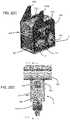
- FIG. 31Ais a simplified, partial, exploded, perspective view diagram of a tow coupling apparatus including load sensor pins 8 , 9 ;
- FIG. 31Bis another simplified, partial, exploded, perspective view diagram of the tow coupling apparatus of FIG. 31A ;
- FIG. 32is a simplified, exploded, perspective view diagram of some of the components of the vehicle tow coupling apparatus of FIG. 31A ;
- FIG. 33is a simplified, partial, cross-sectional view diagram of the tow coupling apparatus of FIG. 31A ;
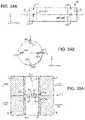
- FIG. 34Ais another simplified, plan view diagram of a load sensor pin
- FIG. 34Bis an end view diagram of the load sensor pin of FIG. 34A ;
- FIG. 35Ais a simplified, partial, axial, cross-sectional view diagram of a load sensor pin for use in the tow coupling apparatus of FIG. 34A ;
- FIG. 35Bis a simplified, partial, cross-section, end view diagram of the load sensor pin of FIG. 35A ;
- FIG. 36is simplified, partial, cross-sectional view diagram of a load sensor pin for use in a tow coupling apparatus
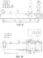
- FIG. 37 through FIG. 44are simplified, schematic, top view diagrams of a portion of a tow coupling apparatus showing various simplified load cases
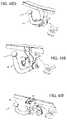
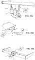
- FIGS. 45A through 45Uare perspective view diagrams of tow hitch assemblies, towed or towing vehicles, and weight sensing assemblies using one or more load sensor pins at various force transmitting components;
- FIG. 46is a simplified, exploded, schematic view diagram of a weight sensor assembly using load sensor pins for sensing a weight of a towed or a towing vehicle;
- FIG. 47is a simplified, schematic, cross-sectional view diagram of the weight sensor assembly of FIG. 46 showing the load sensor pins;
- FIGS. 48, 49A, and 49Bare simplified, schematic, perspective views of a vehicle in which force vectors F FL , F FR , F RR , F RL , and F vehicle representing the weight of a vehicle body are shown;
- FIGS. 50 through 54are schematic diagrams of the weight sensor assembly and load sensor pins of FIGS. 46 and 47 as applied to various types of vehicle suspension assemblies;
- FIGS. 55 and 56are simplified, partial, perspective, and schematic drawings of a front and rear vehicle suspension including various load sensor pins 8 , 9 ;
- FIG. 57is schematic diagram of a vehicle suspension apparatus including load sensor pins
- FIGS. 58 and 59are simplified, partial, perspective, and schematic drawings of a front and rear vehicle suspension including various load sensor pins 8 , 9 ;
- FIG. 60 through 62are schematic diagrams of the weight sensor assembly and load sensor pins of FIGS. 46 and 47 as applied to various types of towed vehicle suspension assemblies;
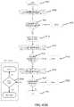
- FIGS. 63A and 63Bare simplified, process flow diagrams of computational methods involving a load sensor pin
- FIGS. 64A and 64Bare schematic drawings of some of the operational components of a load sensor pin 8 or 9 ;
- FIG. 65is a simplified, side, plan view diagram of a portion of a vehicle weight distribution tow coupling apparatus showing a simplified load case
- FIG. 66is a simplified, process flow diagram of a method of cryogenically treating a load sensor pin
- FIGS. 67A through 67Care simplified cross-sectional block diagram of another packaging arrangement similar to but also different than the ones in FIG. 9 ;
- FIG. 68is a graph illustrating the collective output signal from magnetic field sensors representing the measured force acting on load sensor pins.
- a Cartesian coordinate systemis used to describe certain features, components, and directions, and unless otherwise stated or shown in the figures otherwise, the x-axis generally refers to a longitudinal direction, the y-axis generally refers to a transverse direction that is perpendicular to the x-axis, and the z-axis generally refers to a vertical direction that is perpendicular to a plane formed by the x- and y-axes.
- FIG. 1Ashown therein is a simplified, schematic diagram of a load sensor pin 8 (and similar load sensor pin 9 ; as best seen in FIG. 5 ) for use with a tow coupling apparatus, one that is adapted to being attached to a towing vehicle (e.g., passenger automobile car or truck; not shown) at/near the back/rear bumper of the towing vehicle.
- a towing vehiclee.g., passenger automobile car or truck; not shown
- the load sensor pin 8 referred to hereis a “front” load sensor pin given its relative position with respect the load sensor pin 9 ; that is, in one embodiment, the load sensor pin 8 is installed in the tow coupling apparatus such that it would be closer to the front of a towing vehicle when the tow coupling apparatus is mounted to the towing vehicle, whereas the load sensor pin 9 is behind the load sensor pin 8 and thus would be closer to the back of the towing vehicle.
- the relative positions of the load sensor pins 8 , 9may be different than the arrangement shown in the drawings, depending on the particular type of tow coupling application.
- the load sensor pins 8 , 9may include a center portion 120 and longitudinally spaced apart end portions 130 a , 130 b on either side of the center portion 120 . Between the center portion 120 and the end portion 130 a is a magneto-elastically active portion 21 bordered by joints 142 a and 144 a (the same features are shown on the other side of the center portion 120 ).
- the magneto-elastically active portion 21is treated in such a way that a longitudinally-extending portion of the surface of the load sensor pins possess a magneto-elastic active region for producing an external magnetic field/flux, as further described below.
- Each of the load sensor pins 8 , 9are preferably hollow shafts having a wall thickness ranging from about 0.2 mm at its thinnest to about 3 mm at its thickest along its longitudinal dimension, but the actual wall thickness may be determined based on a particular needs of the application in which the load sensor pins 8 , 9 are used.
- the outer surface of the load sensor pins 8 , 9may have portions that are round or flat.
- the dimension 122which spans a portion of the center portion 120 and the magneto-elastically active portion 21 (as well as a portion of the center portion 120 and the magneto-elastically active portion 22 ), may vary by application.
- the dimension 124which is a diameter of the end face of the end portion 130 b of the load sensor pin 8 , 9 (as well as a diameter of the end face of the end portion 130 a of the load sensor pin 8 , 9 ) may also vary as necessary.
- the dimension 126which is the width of the magneto-elastically active portions 22 (as well as the width of the magneto-elastically active portions 21 ) may be about 8 mm to about 24 mm.
- the dimension 128which is a diameter of the inner wall surface of the load sensor pin 8 , 9 at the ends of the end portion 130 a of the load sensor pin 8 , 9 (as well as the a diameter of the inner wall surface of the load sensor pin 8 , 9 at the ends of the end portion 130 b of the load sensor pin 8 , 9 ) may also vary by application.
- All or some of the center portion 120 and the end portions 130 a , 130 bmay be made from non-magnetic materials to keep near field magnetic field generating sources, such as a permanent magnet, magnetized wrench, motor, or solenoid, at a minimum distance from the load sensor pins 8 , 9 to reduce or eliminate (below detection) the path of magnetic fields from those types of sources. This would limit or eliminate the effect these near field sources have on the force dependent field measurements produced by the magneto-elastically active portions 21 , 22 of the load sensor pins 8 , 9 .
- near field magnetic field generating sourcessuch as a permanent magnet, magnetized wrench, motor, or solenoid
- Another way to reduce the influence of external magnetic fields in/on the load sensor pins 8 , 9is to have only the shear areas of the load sensor pins 8 , 9 made of ferromagnetic material. That is, it is not necessary for the rest of the load sensor pins 8 , 9 to be made from a ferromagnetic material, and in some instances it is rather undesirable as such materials only act as a flux director for channeling external magnetic fields towards the magnetic field measurement coils (not shown).
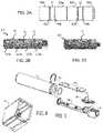
- FIGS. 1B and 1Care additional simplified side and perspective views of the load sensor pins 8 , 9 of FIG. 1A .
- FIG. 1Dshown therein is a simplified side view of the load sensor pins of FIGS. 1A, 1B, and 1C , having bushings 690 a , 690 b , and 690 c (of the kind shown in FIG. 1E ) press fitted onto the pin 8 , 9 .
- Two smaller bushings 690 a , 690 cmay be positioned on opposite ends of the load sensor pins 8 , 9 as shown.
- One larger bushing 690 bwhich may include an alignment groove 23 , may be positioned at the center of the load sensor pins 8 , 9 as shown.
- the bushingsare preferably made of a non-ferromagnetic material such as tin brass, and may be press fitted by first supercooling the load sensor pins 8 , 9 and/or heating the bushings 690 a , 690 b , 690 c and then sliding them into place and allowing the pins/bushings to warm/cool to an ambient temperature.
- the press-fitted bushingsmay improve the response, by the load sensor pins 8 , 9 , to applied forces across different drawbar variations.
- the assembly shownmay improve the tolerance of the fully assembled load sensor pin stack up (following end machining after press fitting the two smaller bushings 690 a , 690 c ).
- the arrangementmay allow for maximizing the sleeve diameter for better magnetic isolation with respect to the casting of the body of the load sensor pins 8 , 9 (i.e., the bushings may provide for a larger signal and thus a better signal to noise ratio).
- the bushingsmay provide for a larger signal and thus a better signal to noise ratio.
- FIG. 2Ashown therein is a simplified, schematic diagram of another aspect of the load sensor pin 8 , 9 of FIG. 1A in which the center portion 120 is divided into two separate center portions 120 a , 120 b , separated by a joint.
- all or some of the center portions 120 a , 120 b , along with their adjacent magneto-elastic active portions 21 , 22are made from a material and/or treated as described above in such a way that they produce an external magnetic field/flux.
- FIGS. 2B and 2Care additional simplified side and perspective views of the load sensor pin 8 , 9 of FIG. 2A , showing the two portions 120 a , 120 b , separated by an alignment groove 23 .
- the different materials of the various portionscould be welded together (e.g. using friction welding).
- Another possibilitywould be to take a load sensor pin 8 , 9 constructed of austenitic stainless steel (non-magnetic) and transform the shear areas to a martensitic material through the process of cold working thus forming the magneto-elastic active portions 21 , 22 .
- the load sensor pin 8includes a retaining clip 302 , a printed circuit board 304 , a set of connector pins 306 , a support member 308 having a pin connector housing 311 (as also shown in FIG. 4 ) on a terminating end, and a pair of sealing rings 310 .
- the retaining clip 302is used to fix the support member 308 in a way that minimizes movement after it is fixed in its final assembled state.
- the printed circuit board 304may have one or more (such as four) magnetic field sensors (described below) mounted thereon each with leads for connecting to the set of connector pins 306 .
- the printed circuit board 304includes a suitable processor, memory, and embedded software (not shown).
- the set of connector pins 306include insert molded pins on one end for extending up and through pre-drilled through-holes on the printed circuit board 304 for connecting to the one or more magnetic field sensors and other circuit components on the printed circuit board 304 .
- the other end of the set of connector pins 306terminate with suitable latch-type or friction fit-type pins that connect with a suitable connector of an electrical harness (as best seen in FIG. 12A ).
- the sealing rings 310are used to prevent anything from entering the interior of the load sensor pin 8 .
- the load sensor pin 9includes a retaining clip 602 , a printed circuit board 604 , a set of connector pins 606 , a support member 608 , a pair of sealing rings 610 , and a connector housing 611 .
- the retaining clip 602is used to fix the support member 608 after it is fixed in its final assembled state to prevent movement.
- the printed circuit board 604may have one or more (such as eight) magnetic field sensors (not shown) mounted thereon each with leads for connecting to the connector pins 606 , which in turn lead to a flat, circular-shaped printed circuit board.
- the printed circuit board 604includes a suitable processor, memory, and embedded software (not shown).
- a micro ribbon or cable(as shown in FIG. 8 ) connects the printed circuit board 604 and a circular printed circuit board.
- the flat, circular-shaped printed circuit boardconnects to a four-pin connector inside the connector housing 611 .
- the sealing rings 610are used to prevent anything from entering the interior of the load sensor pin 9 .
- FIG. 9shown therein is a simplified, partial, cross-sectional, plan view diagram of the “front” and “back” load sensor pins of FIGS. 3 and 6 and some of the components of a tow coupling apparatus as they could be employed in connection with a tow coupling apparatus (for ease of reference, the two load sensor pins are shown with load sensor pin 9 on top of load sensor pin 8 ). As shown, the center portions 120 of the load sensor pins 8 , 9 are rigidly fixed inside the through-holes of a bracket 902 that generally surrounds the load pins 8 , 9 .
- the end portions 130 a , 130 b of the load sensor pins 8 , 9are further rigidly fixed inside corresponding through-holes of the yoke-like projections 904 a , 904 b of a generally U-shaped adapter 904 (supporting yoke) that surrounds the bracket 902 .
- Bushings 906 a , 906 b , 906 c , 906 dsurround respective portions of the load sensor pin 9
- bushings 908 a , 908 b , 908 c , 908 dsurround respective portions of the load sensor pin 8 .
- the bushingsmay be brass or some other material.
- no bushingsare used between the end portions 130 a , 130 b of the load sensor pins 8 , 9 and the respective through-holes of the side yoke-like projections 904 a , 904 b of the adapter 904 .
- the load sensor pins 8 , 9are in direct contact with the walls of the through-holes.
- the load sensor pins 8 , 9are made from one or more materials, in addition to ferromagnetic materials, and are constructed in such a way that they are suitable for forming the magneto-elastic active regions 21 , 22 .
- the chosen materials and construction of the various portions of the load sensor pins 8 , 9should be such that the nature of the shaft of the load sensor pins 8 , 9 is one that is elastically deformable. This provides for the relative movement between the center portions 120 (caused by a force imparted by the bracket 902 on the center portions 120 ) and the rigidly fixed end portions 130 a , 130 b (maintained in a stationary position by the adapters 904 ).
- the eccentric deformation caused by forces imparted on the load sensor pins 8 , 9causes the magneto-elastic active regions 21 , 22 to produce the external magnetic field/flux as previously described.
- FIGS. 10A through 10Dshown therein are a simplified cross-sectional, perspective view drawings of others aspects of a load sensor pin 8 , 9 .
- a load sensor pin 8has a length along its longitudinal direction such that the slot 312 (and slot 612 ) for receiving the retaining clip 302 is outside the bushing 908 d ( 906 d in the case of the load sensor pin 9 ).
- the slots 312 , 316may be about 1.5 mm wide and have an inner diameter of about 24 mm, and they may be about 4 mm from the end of the load sensor pin 8 .
- FIG. 10Aa load sensor pin 8 has a length along its longitudinal direction such that the slot 312 (and slot 612 ) for receiving the retaining clip 302 is outside the bushing 908 d ( 906 d in the case of the load sensor pin 9 ).
- the slots 312 , 316may be about 1.5 mm wide and have an inner diameter of about 24 mm, and they may be about 4 mm from the end of the
- the retaining clip 302includes a raised flange or post 302 a that fits inside a pole yoke opening 314 as best seen in FIG. 10B to prevent the retaining clip 302 from slipping out of its slot 312 (similarly, the retaining clip 602 includes a raised flange or post to prevent the retaining clip 602 from slipping out of its slot 612 ).
- the pole yoke opening 314may extend through the wall of the load sensor pin 8 , for example to accept a raised flange or post 302 a having about a 2 mm length.
- FIG. 10Done possible configuration for the retaining clips 302 , 602 is shown.
- FIG. 11A and FIG. 11Bshown therein is a simplified, schematic diagram of one of the load sensor pins 8 , 9 of FIG. 2A inside a shielding device 910 , and a simplified, exploded, perspective view diagram of the components of a load sensor pin 8 , 9 showing a printed circuit board 304 , 604 between two elongated magnetic field shielding members 912 a , 912 b , respectively.
- FIG. 11A and FIG. 11Bshown therein is a simplified, schematic diagram of one of the load sensor pins 8 , 9 of FIG. 2A inside a shielding device 910 , and a simplified, exploded, perspective view diagram of the components of a load sensor pin 8 , 9 showing a printed circuit board 304 , 604 between two elongated magnetic field shielding members 912 a , 912 b , respectively.
- FIG. 11A and FIG. 11Bshown therein is a simplified, schematic diagram of one of the load sensor pins 8 , 9 of FIG. 2A
- the shielding device 910may be a box or other shape and is made using materials with high magnetic permeability, which shunts an external magnetic field by offering a path of low resistance to the field and thereby minimizing or eliminating the influence of the field on the force dependent field measurements produced by the load sensor pins 8 , 9 .
- the shielding members 912 , 912 balso help to minimize or eliminate the influence of the field on the force dependent field measurements produced by the load sensor pins 8 , 9 . Shielding effects are further described in Applicant's U.S. Pat. No. 8,578,794 (Magneto-elastic Torque Sensor with Ambient Field Rejection), which is incorporated herein by reference in its entirety.
- FIG. 12Ashown therein is a simplified, partial, perspective view diagram of some of the components of a load sensor pin having a secondary magnetic field sensor 916 .
- FIG. 12Bshows another simplified, partial, perspective view diagram of some of the components of the load sensor pin of FIG. 12A .
- the components of one of the load sensor pins 8 , 9is shown in which its respective printed circuit board 304 , 604 includes primary magnetic field sensors 914 a , 914 b and a secondary magnetic field sensor 916 .
- the secondary magnetic field sensor 916may be a 3-axis compass sensor (either standalone or as part of a 9-axis sensor), which is used to detect the presence of external magnetic fields in the case that the shielding elements described above are not effective in eliminating all external fields.
- each of the load sensor pins 8 , 9could include extra sensing coils arranged in a way to minimize the influence of external magnetic fields on the measurement of the forces by the primary magnetic field sensors 914 a , 914 b.
- the effects of external magnetic fieldsmay also be taken into account by computational means using a suitable algorithm, which may be processed by embedded software on the printed circuit board 304 , 604 , or in a separate electronics module 980 connected to the printed circuit board 304 , 604 via cable connector 982 . Due to the mechanical configuration of a sensor system assembly (especially ones with two or more load sensor pins 8 , 9 or two sensing planes), there can be certain relationships between the forces detected by the load sensor pins 8 , 9 that have to be fulfilled. An external field is likely to cause an implausible relationships/combination of individual forces measured, which an algorithm could detect and compensate for.
- FIG. 13shown therein is a simplified, partial, perspective view diagram of some of the components of a tow coupling apparatus showing front load sensor pin 8 and back load sensor pin 9 for coupling a towing vehicle to a towed vehicle.
- the tow coupling apparatusincludes a bracket 902 attached to a receiver tube 920 , and a generally U-shaped adapter 904 attached to a hitch tube 922 .
- the hitch tube 922is a longitudinally extending, round, oval, square, or other shape member of the type typically used to attach to a towing vehicle (not shown) near the rear bumper of the towing vehicle.
- the hitch tube 922is the component that couples the tow coupling apparatus to the towing vehicle to transmit force (generated by the towing vehicle's engine) to a towed vehicle (not shown), such as a trailer.
- Bolts or other fastening meansmay be used to securely attach the hitch tube 912 to the towing vehicle.
- the adapter 904has two side yoke-like projections 904 a , 904 b extending approximately 90-degrees from a base portion such that they are parallel to each other.
- Each side wallincludes through-holes: first and second through-holes 924 - 1 , 924 - 2 on the side wall 904 b , and third and fourth through-holes 924 - 3 , 924 - 4 on the side wall 904 a , such that the first and third through-holes 924 - 1 , 924 - 3 are axially aligned with each other, and the second and fourth through-holes 924 - 2 , 024 - 4 are also axially aligned with each other.
- the end portions 130 a , 130 b of the load sensor pins 8 , 9are rigidly fixed inside the through-holes of the side yoke-like projections 904 a , 904 b of the adapter 904 , in some cases using collars or bushings, that surrounds the bracket 902 as shown.
- the bracket 902which may be a single member or two separate members arranged on front and back sides of the hitch tube 922 , fits between the two side yoke-like projections 904 a , 904 b of the adapter 904 when the tow coupling apparatus components are in an assembled state.
- the bracket 902includes a front portion and a back portion. The front portion and the back portion each includes a through-hole (not shown) axially aligned with the through-holes on the adapter 904 when the components are in the assembled state.
- Through-holes on the front and back portions of the adapter 904may be slightly larger than the through-holes 924 - 1 , 924 - 2 , 924 - 3 , 924 - 4 such that shear forces transmitted from the receiver tube 920 are introduced into the load sensor pins 8 , 9 by abutment surfaces of the through-holes 924 - 1 , 924 - 2 , 924 - 3 , 924 - 4 in the adapter 904 and abutment surfaces of the through-holes in the bracket 902 .
- the bracket 902 and the adapter 904are each made of a material selected from suitable materials that resist deforming over time under a range of expected applied forces.
- the thickness of the base portion of the adapter 904 in the configuration shownmay be 8 mm.
- the thickness of the base portion of the adapter 904may be 10 mm, which may be achieved, for example, by modifying the placement of the various through-holes and changing other dimensions of the adapter 904 .
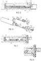
- FIG. 14shown therein is another simplified, partial, perspective view diagram of the components of the tow coupling apparatus showing front load sensor pin 8 and back load sensor pin 9 .
- an alternative approach to using the adapter 904is shown.
- the alternative adapterincludes four separate adapters 904 - 1 , 904 - 2 , 904 - 3 , 904 - 4 each separately connected directly to a hitch tube 922 as shown.
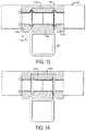
- FIG. 15 and FIG. 16shown therein are simplified, partial, cross-sectional, end view diagrams of the components of the tow coupling apparatus of FIG. 13 .
- the lower edge of the side yoke-like projections 904 a , 904 b of the adapter 904include a beveled edge such that there is a gap of about 7 mm between the bevel edge and the closest edge of the receiver tube 920 .
- the gap between the upper edge of the bracket 902 and the base portion of the adapter 904is also a gap of about 0.5 mm between the upper edge of the bracket 902 and the base portion of the adapter 904 (the thickness of the base portion here could be about 8 mm or as needed to provide rigidity for the side yoke-like projections 904 a , 904 b ).
- the gap between the upper edge of the bracket 902 and the base portion of the adapter 904is increased from 0.5 mm to 5 mm (the thickness of the base portion here could be about 10 mm to provide additional rigidity for the side yoke-like projections 904 a , 904 b ).
- Various other dimensions (thickness) of the base portion of the adapter 904are also contemplated and may be suitable for different expected forces or loads on the tow coupling apparatus components. Also shown are press-fit bushings having a pre-determined radial thickness inserted into the axially-aligned through-holes of the bracket.
- FIG. 17A and FIG. 17Bshown therein are simplified, partial, perspective view diagrams of the tow coupling apparatus of FIG. 14 .
- a drawbar 930is shown inserted into the receiver tube 920 and may be fastened in the receiver tube 920 with a connecting pin (not shown).
- the drawbar 930is the connection member between the tow coupling apparatus and the towed vehicle (e.g., trailer), and thus is a force-transmitting member that can be monitored by use of the load sensor pins 8 , 9 as previously described.
- FIG. 18Ais a simplified, partial, perspective view diagram of some of the components of the tow coupling apparatus of FIG. 14 showing a first load case in which a force is applied to the proximate or free end of the drawbar 930 (i.e., the end closest to the viewer).
- This applied forcewill be transmitted to the distal or pinned end of the drawbar 930 inside the receiver tube 920 . That is, the force corresponding to the transmitted force at the distal end of the drawbar 930 by the towed vehicle may be transmitted to the receiver tube 920 . That force then acts on the bracket 902 attached to the receiver tube 920 .
- the shear forcecauses the magneto-elastically active portions 140 a , 140 b to output a magnetic field that is detectable by magnetic field sensors 914 a , 914 b.
- the force transmitted to the back load sensor pin 9may be determined with respect to the adapters 904 - 2 , 904 - 4 .
- the output signals from the magnetic field sensors associated with the load sensor pin 9may be received in a suitable algorithm, for example one that is embedded on a circuit board having a suitable processor located inside the load sensor pin 9 , or in a separate module 980 ( FIG. 12A ) that could be integrated into the towing vehicle electronics.
- the received output signals from the load sensor pin 9may be indicative of the magnetic field/flux exhibited by the load sensor pins, and thus may be used to determine that a force has vector components of 6653 N in the x-direction and ⁇ 5138 N in the y-direction (associated with the x-y-z Cartesian coordinate system shown). Moreover, the received output signals may be further used to determine that the other force vector components are ⁇ 6245 N in the x-direction and 6 N in the y-direction as shown.
- the algorithm/processormay compute that the force applied to the proximate end of the drawbar 930 has a magnitude of 3514 N and is applied in the direction shown (i.e., toward the right or in the y-direction).
- the table belowindicates the forces that may be determined as a result of forces transmitted to the load sensor pins 8 , 9 .
- the information about the applied force at the proximate end of the drawbar 930 , and related informationmay be provided to the towing vehicle for any number of useful purposes, such as displaying the information and/or related information to the vehicle operator or as input to a vehicle system such as a braking system, a stability system, a transmission system, a trailer backing system, or an engine controller system.
- a vehicle systemsuch as a braking system, a stability system, a transmission system, a trailer backing system, or an engine controller system.
- FIG. 18Bshown therein is another simplified, partial, perspective view diagram of some of the components of the tow coupling apparatus of FIG. 14 showing a different load case as summarized in the following table.
- FIG. 19A , FIG. 19B , and FIG. 19Cshown therein are simplified, partial, perspective view diagrams of the vehicle tow coupling apparatus of FIG. 14 in which a shielding device 190 is used to surround the load sensor pins 8 , 9 for shielding the magneto-elastically active portions 140 a , 140 b and the magnetic field sensors 914 a , 914 b from external magnetic fields.
- the shielding device 190is preferably made from or utilizes highly magnetically permeable materials to conduct external magnetic fields away from the load sensor pins 8 , 9 .
- the shielding device 190provides openings for sheathed cables 192 , 194 , which connect the electronics of the load sensor pins 8 , 9 to external circuits, to pass through the shielding device 190 .
- Even a thin metal shielding device 190is able to provide good shielding.
- An external AC magnetic fieldwill create eddy currents inside of the shield material, which in turn will create a magnetic field that opposes the incident field, thereby cancelling the incident field.
- the shielding materialmay be magnetic or non-magnetic but should have a high electric conductivity.
- FIG. 20Ashown therein is a simplified, side view diagram of the tow coupling apparatus of FIG. 14 showing another load case.
- a drawbar 930 with a ball-style hitch(typically welded or bolted to the proximate or free end of the drawbar 930 ) is shown inserted in the receiver tube 920 and held in place with a fastening pin (other devices for connecting the drawbar and receiver are also contemplated).
- the large arrowsindicate the forces that might act on the assembled tow coupling apparatus in the plane of the diagram (x-z plane, assuming the y-direction is out of the page).
- An algorithm(such as in the form of embedded software in/on the load sensor pins 8 , 9 or in the separate module 980 ( FIG. 12A )) may utilize values for the following variables (all linear dimensions are measured along the x- or z-direction as shown):
- Inputs associated with each of the above variableswill be processed by the aforementioned processor which executes software algorithms that are embedded in/on the memory or storage device on the printed circuit boards 304 , 604 of the load sensor pins 8 , 9 , or that are embedded in/on a printed circuit board of the separate module 980 outside the load sensor pins 8 , 9 .
- the inputsare used in at least the following equations:
- the softwarecomputes a tongue force (F-tongue), tow force (F-tow), and a sway force (F-sway) according to industry-specific and federal specifications, such as those of Ultimate Load (per SAE J684 for Hitch Test Loads), and Ultimate Loads (per SAE J684 Strength Test Loads for Balls and Trailer couplings). Other methods and standards may also be used, including those for other countries/regions (e.g., European Union).
- the embedded softwaremay be used to receive signals from various other sensors (not shown) and output a signal containing information useful in determining or assessing a load weight gauge (measuring the tongue load of a coupling between the tow and towing vehicles), a tow load weight shift alert, an unsafe towed vehicle load distribution alert, a towing vehicle limit notification, an automated towed vehicle brake control (closed loop) signal, a low/flat towed vehicle tire notification, a check towed vehicle brake notification, a closed loop braking control, a towing vehicle shift control, a towing vehicle engine control, and a towing vehicle stability control.
- a load weight gaugemeasuring the tongue load of a coupling between the tow and towing vehicles
- a tow load weight shift alerte.g., a tow load weight shift alert
- an unsafe towed vehicle load distribution alerte.g., an unsafe towed vehicle load distribution alert
- a towing vehicle limit notificatione.g., a towing vehicle limit notification
- the softwaremay provide a signal corresponding to a value in a pre-determined output range (provided in, e.g., N and lb), an ultimate or maximum load weight carrying output (provided in, e.g., N and lb), and an ultimate or maximum ball load and trailer hitch output (also in, e.g., N and lb).
- a pre-determined output rangeprovided in, e.g., N and lb
- an ultimate or maximum load weight carrying outputprovided in, e.g., N and lb
- an ultimate or maximum ball load and trailer hitch outputalso in, e.g., N and lb.
- Additional software inputsmay include load sensor pin outer diameter, inner diameter, wall thickness, free length L, and shear points (all in millimeters).
- Calculated stress valuesmay include maximum shear stress and bending stress, among others (all in N/mm 2 ).
- a static safety factormay also be computed.
- FIGS. 20B through 20Kshown therein are simplified, partial cross section, top or side view diagrams of alternative arrangements of a tow coupling apparatus having the following arrangements of components: the load sensor pins 8 , 9 , the bracket 902 , the adapter 904 , the receiver tube 920 , the hitch tube 922 , and the drawbar 930 .
- the bushings 690 a , 690 b , and 690 cmay be press fitted to the load sensor pins 8 , 9 , or press fitted in the through-holes of the bracket 902 and/or the adapter 904 .
- Table 4provides a summary of the various possible configurations shown in the drawings.
- the table and drawingsare not limiting; other possible arrangements of the components is possible, including the position of the load sensor pins 8 , 9 above or below the receiver tube, and the location of the gap where the ends of the load sensor pins 8 , 9 are press fitted into the adapter 904 (thereby providing a movement degree of freedom in the x-axis towing direction).
- FIG. 21shown therein is a simplified, side view diagram of a tow coupling apparatus and vehicle components.
- the tow coupling apparatusis mounted such that it does not interfere with a bumper step 940 (which is above the hitch tube 922 ) and spare tire 944 (which is behind the hitch tube 922 , in some cases by only a few inches, such as 3 inches).
- Spare tires stored below a towing vehicle's body frame or other componentsare typically lowered to the ground by a cable and winch mechanisms (not shown), and can swing on the cable and potentially strike the tow coupling apparatus.
- an angled guide member 942is positioned forward of the tow coupling apparatus and between the tow coupling apparatus and the spare tire 944 as shown.
- FIGS. 22A through 22Eshown therein are simplified, partial, cross-sectional, and perspective view diagrams of a tow coupling apparatus, including load sensor pins 8 , 9 , for a towing vehicle, which could be a private or commercial passenger pickup truck or an off-road agricultural vehicle, among others.
- a tow coupling apparatusincluding load sensor pins 8 , 9 , for a towing vehicle, which could be a private or commercial passenger pickup truck or an off-road agricultural vehicle, among others.
- the two load sensor pins 8 , 9 of the tow coupling apparatus of FIGS. 22A through 22Eare positioned below the receiver tube 920 .
- FIG. 22Ashows a perspective view
- FIG. 22Bshows a side-view of the tow coupling apparatus in which a bracket 902 generally surrounds the middle portions of the load sensor pins 8 , 9 , and is attached to a receiver tube 920 .
- a separate, generally U-shaped adapter 904pins the left and right ends of each of the load sensor pins 8 , 9 , and is attached to a hitch tube 922 (which, as shown, is part of a towing vehicle bumper assembly).
- a drawbar 930is shown inserted into the receiver tube 920 and fastened in the receiver tube 920 using a connecting pin 103 .
- the two load sensor pins 8 , 9are used to interconnect the hitch tube 922 of the vehicle and the drawbar 930 (via the bracket 902 and adapter 904 , respectively), such that any force acting on the drawbar 930 will cause shear forces to be observable by the load sensor pins 8 , 9 as previously generally described.
- FIG. 22Cshows another perspective view of the arrangement of the bracket 902 , the adapter 904 , the receiver tube 920 , and the load sensor pins 8 , 9 of FIG. 22A . Also shown are a pin connector housing 311 , which is protruding from the proximate end of the load sensor pin 8 , and a pin connector housing 611 , which is protruding from the proximate end of the load sensor pin 9 .
- flanges 550 a , 550 bextending from the upper portions of the left and right sides of the adapter 904 , thereby forming left and right surfaces 552 a , 552 b that may be used to attach the adapter 904 securely to corresponding surfaces of the hitch tube 922 (e.g., by a mechanical weld where the surfaces 552 a , 552 b contact the outer surface of the hitch tube 922 approximately near the center of the hitch tube 922 ), thereby achieving stability in the longitudinal x-axis, lateral y-axis, and vertical z-axis.
- FIG. 22Dshows the tow coupling apparatus of FIG. 22A as viewed from the front of the vehicle looking toward the rear or back end of the vehicle. From this perspective, only the load sensor pin 8 is partially visible, as it is the load sensor pin closest to the bumper and the front of the vehicle in this configuration.
- FIG. 22Eis a cross-sectional side view of the tow coupling apparatus taken along the plane A-A as indicated in FIG. 22D .
- FIGS. 23A through 23Cshown therein are simplified, partial, cross-sectional, and perspective view diagrams of another tow coupling apparatus, including load sensor pins 8 , 9 , for a towing vehicle.
- the two load sensor pins 8 , 9are positioned above the receiver tube 920 and below the hitch tube 922 .
- the two load sensor pins 8 , 9are used to interconnect the hitch tube 922 of the vehicle and the drawbar 930 (via the bracket 902 and adapter 904 , respectively), such that any force acting on the drawbar 930 will cause shear forces to be observable by the load sensor pins 8 , 9 as previously generally described.
- FIGS. 24 and 25shown therein are simplified, schematic, perspective view diagrams of tow coupling apparata, each including a single load sensor pin 8 (or 9 ) for a towing vehicle.
- the hitch tube 922is used in place of the bracket 902 , and the adapter 904 is rotated 90-degrees in the x-y plane relative to the orientation of the brackets previously described.
- the single load sensor pin 8 (or 9 )is also rotated about its longitudinal axis 90-degrees such that its longitudinal axis is parallel to and with the longitudinal axis of the vehicle.
- a force acting on the receiver tube 920will be observed by the load sensor pin 8 or 9 .
- the single load sensor pin 8is positioned to the rear of the hitch tube 922 and within the adapter 904 for sensing longitudinal (Fx) and vertical (Fz) forces acting on the pin.
- FIG. 26is a simplified, perspective view diagram of one component of a tow coupling apparatus showing upper and lower load sensor pins 8 , 9 for use with a towed vehicle coupler 220 , which mates with a towing vehicle coupler 230 .
- the load sensor pins 8 , 9are arranged generally vertically (along z-axis) with respect to each other (as compared to, for example, the embodiments of FIG. 13 and FIG.
- the two load sensor pins 8 , 9are positioned in the towed vehicle coupler 220 in respective upper and lower brackets 222 - 1 , 222 - 2 , with or without bushings.
- the towing vehicle coupler 230includes four adapters 232 - 1 , 232 - 2 , 232 - 3 , 232 - 4 such that the through-holes on the upper bracket 222 - 1 are axially aligned with the through-holes of the adapters 232 - 1 , 232 - 2 , and the through-holes on the lower bracket 222 - 2 are axially aligned with the through-holes of the adapters 232 - 3 , 232 - 4 .
- the load sensor pins 8 , 9may be rigidly fixed in the through-holes, such that the couplers 220 and 230 may be coupled together as illustrated in FIG. 28 .
- the towed vehicle coupler 220is modified such that it includes a hitch part 220 a having a bracket 250 and through-holes 252 , and a coupler part 220 b having through-holes 254 .
- the through-holes 252 , 254permit a user to vertically adjust (z-axis) the relative position of the hitch part 220 a and the coupler part 220 b with respect to each other (a fastening pin, not shown, is inserted into the through-holes 252 , 254 , once they are axially aligned).
- the load sensor pins 8 , 9may be rigidly fixed in the through-holes, such that the tow coupling apparatus may be coupled together as illustrated in FIG. 29B .
- FIG. 29Cshown therein is a simplified, perspective view diagram of another vehicle tow coupling apparatus 100 incorporating the load sensor pins 8 , 9 .
- the coupling apparatus 100includes a towed vehicle coupler 220 and a towing vehicle coupler 230 (which is insertable in receiver tube 920 as previously described).
- the vehicle coupler 220consists of a hitch part 220 a , having respective upper and lower brackets 222 - 1 , 222 - 2 , and a coupler part 220 b .
- the hitch part 220 ais coupled to the coupler part 220 b using two or more load sensor pins 8 , 9 .
- the respective middle-portions of the two load sensor pins 8 , 9are positioned in through-holes of respective upper and lower brackets 222 - 1 , 222 - 2 (as partially shown in FIG. 29D ); and the respective ends of the two load sensor pins 8 , 9 are positioned in corresponding respective left and right through-holes (not shown) in the left and right side walls of the coupler part 220 b.
- the coupler part 220 bis further coupled to the towing vehicle coupler 230 using two or more removable fastening pins 224 a , 224 b .
- the respective middle-portions of the fastening pins 224 a , 224 bare positioned in through-holes (not shown) in the towing vehicle coupler 230 (as partially shown in FIG. 29D ); and the respective ends of the two fastening pins 224 a , 224 b are positioned in corresponding respective left and right side walls of the coupler part 220 b .
- the fastening pins 224 a , 224 bpermit a user to manually vertically adjust (z-axis) the relative position of the coupler part 220 b with respect to the towing vehicle coupler 230 so that the height of the ball on the end of the hitch part 220 a can be adjusted to accommodate varying heights of different trailer coupling devices.
- the height adjustmentmay be performed by physically removing the two fastening pins 224 a , 224 b , sliding the coupler part 220 b up or down as indicated in FIG. 29D , and reinserting the two fastening pins.
- a motorized height adjustment mechanismmay be used instead of fastening pins.
- Each of the load sensor pins 8 , 9may be positioned in the through-holes with one or more bushings (as shown in, for example, FIG. 1E ).
- the bushingmay be press fitted to the load sensor pins 8 , 9 , or they may be press fitted in the through-holes of the respective upper and lower brackets 222 - 1 , 222 - 2 , and/or press fitted in the left and right through-holes in the left and right side walls of the coupler part 220 b.
- the load sensor pin 8is vertically (viewed in the z-direction) above the point where the ball, located at the end of the hitch part 220 a , and the hitch of the towed vehicle (i.e., trailer), connect.
- the load sensor pin 9is shown generally on the same horizontal (x-y) plane as the connection point.
- each load sensor pin 8 , 9at least one magnetic field sensor device may be arranged to have a predetermined and fixed spatial position inside the pin to detect forces in the x- and z-axis directions.
- the load sensor pin 8 and the load sensor pin 9may, during operation, output respective signals relative to those directions.
- the load sensor pin 8is not used for measuring forces and only the load sensor pin 9 measures forces/output respective signals in two directions (e.g., x- and z-axis) and computes forces on the hitch relative to all three x-y-z directions.
- FIGS. 30A and 30Bshown therein are simplified, schematic, side and top view diagrams of the vehicle tow coupling apparatus of FIGS. 29C and 29D along with additional electronic components.
- FIG. 30Ashows a side-view of the vehicle tow coupling apparatus 100
- FIG. 30Bshows a corresponding top view of the tow coupling apparatus 100 .
- the respective ends of the upper load sensor pin 8are shown positioned in corresponding respective left and right through-holes in the left and right side walls of the coupler part 220 b without a gap, thereby rigidly-fixing the ends in the through-holes.
- the respective ends of the lower load sensor pin 9are positioned in corresponding respective left and right through-holes in the left and right sides of the coupler part 220 b with a gap, thereby allowing the ends to be rigidly-fixed in the longitudinal (x-axis) and lateral (y-axis) towing directions while providing a movement degree of freedom in the vertical (z-axis).
- the location of the gapmay instead be switched such that the load sensor pin 8 has a movement degree of freedom and the load sensor pin 9 does not.
- an electrical connector and harness 226which is connected to the electronic components of the load sensor pins 8 , 9 via cable connector 982 .
- the electrical connector and harness 226may include, for example, a round 7-pin connector (not shown) for connecting to an electrical system of the towing vehicle.
- signals from the load sensor pins 8 , 9may be processed, compared to one or more criteria, and used to convey information via a visual display or an audio speaker integrated in the towing vehicle or via a display or speaker associated with a remote or portable device 234 .
- the signal processingmay be performed on the electronic of the load sensor pins 8 , 9 , a separate control module, or on the vehicle onboard computer.
- the conveyed informationis provided to an operator, and may convey a state or status of the towing vehicle, the towed vehicle, and/or the tow coupling apparatus 100 using numerical, textual, or other indicia (e.g., color graphics).
- the informationmay include, but is not limited to, a state or status of: a rated tongue load (e.g., whether safe, exceeded, or within an acceptable range), a tongue load (such as a “tongue light” or other unsafe situation), an indication of the rated towing load being acceptable or exceeding a safe value, a trailer weight (calculated from the tow force signal and a vehicle acceleration), a tongue to trailer weight ratio (e.g., within or outside an acceptable range), a physical shifting in a trailer load, an amount of trailer sway, a check trailer tire pressure (passenger or driver), a stuck brake situation, and a low tire pressure.
- a rated tongue loade.g., whether safe, exceeded, or within an acceptable range
- a wireless communications devicemay include a radio-frequency transceiver programmed and enabled to communicate the information according to a data transmission protocol (such as, for example, Bluetooth®) to the remote or portable devices 234 , which may be a smartphone, a portable computing device, or a fixed computing device.
- a data transmission protocolsuch as, for example, Bluetooth®
- the tow coupling apparatus 100includes a sensor assembly 1 for force sensing.
- the sensor assemblyincludes a first portion 2 (supporting yoke) having a first through-hole 3 and a second through-hole 4 , a second portion 5 (receiving tube) having a third through-hole 6 and fourth through-hole 7 .
- the third and fourth through-holes 6 , 7are positioned in correspondence to the first and second through-holes 3 , 4 .
- the second portiondefines a Cartesian coordinate system having a longitudinal x-axis direction, a transversal y-axis direction, and a vertical z-axis direction.
- the longitudinal directionextends in the direction of longitudinal extension of the second portion.
- the transversal directionextends in a direction perpendicular to the longitudinal direction and in a horizontal plane.
- the vertical directionextends in a direction that perpendicular to the longitudinal direction and the transversal direction.
- the sensor assembly 1further includes a first load sensor pin 8 and a second load sensor pin 9 .
- the load sensor pin 8is arranged such that it extends through the first and third through-holes 3 , 6 .
- the load sensor pin 9is arranged such that it extends through the second and fourth through-holes 4 , 7 .
- the first portion 2is coupled to the second portion 5 via the first and second load sensor pins 8 , 9 .
- At least one out of the first and the second load sensor pin 8 , 9includes at least one magneto-elastically active region 10 (as shown in FIG. 33 ) that is directly or indirectly attached to or forms a part of the load sensor pin 8 , 9 in such a manner that mechanic stress of the load sensor pin 8 , 9 is transmitted to the magneto-elastically active region 10 .
- the magneto-elastically active region 10includes at least one magnetically polarized region such that a polarization of the polarized region becomes increasingly helically shaped as the applied stress increases.
- the at least one load sensor pin 8 , 9further includes a magnetic field sensor means arranged approximate the at least one magneto-elastically active region 10 for outputting a signal corresponding to a stress-induced magnetic flux emanating from the magnetically polarized region.
- the magnetic field sensor meansincludes at least one direction sensitive magnetic field sensor L.
- the at least one direction sensitive magnetic field sensoris configured for determination of a shear force in at least one direction.
- the at least one direction sensitive magnetic field sensor Lis in particular arranged to have a predetermined and fixed spatial coordination with the respective load sensor pin 8 , 9 .
- the load sensor pin 8 , 9includes the at least one direction sensitive magnetic field sensor L is at least partially hollow.
- the at least one direction sensitive magnetic field sensor Lis arranged inside the interior of the pin 8 , 9 .
- the first through-hole 3 and the third through-hole 6are configured such that they encompass the first load sensor pin 8 in a positive-fitting manner.
- the first load sensor pin 8extends through the first and third through-holes 3 , 6 , and the first load sensor pin 8 is supported in at least two rotational degrees of freedom and at least two translational degrees of freedom by abutting surfaces of the through-holes.
- the second load sensor pin 9is encompassed by the second through-hole 4 in a positive-fitted manner.
- the second load sensor pin 9extends through the second through-hole 4 , and the second load sensor pin 9 is supported in at least two rotational degrees of freedom and at least two translational degrees of freedom by abutting surfaces of the second through-hole 4 .
- the fourth through-hole 7is configured such that the second load sensor pin 9 has one additional degree of freedom of movement (compared to the first load sensor pin 8 in the third through-hole 6 ) within the fourth through-hole 7 .
- the second load sensor pin 9extends through fourth through-hole 7 , and the second load sensor pin 9 is supported in at least two rotational degrees of freedom and at least one translational degree of freedom by abutting surfaces of the through-holes.
- the number of translational degrees of freedom of the second load sensor pin 9 in the fourth through-hole 7is one more than the number of translational degrees of freedom of the first load sensor pin 8 the third through-hole 6 .
- the additional degree of freedomis a translational degree of freedom that extends in the longitudinal x-axis direction.
- the first portion 2has a yoke-like shape, wherein yoke legs 11 of the first portion comprise the first through-hole 3 and second through-hole 4 .
- the second portion 5has a tubular shape, wherein side walls and/or a center wall of the second portion 5 comprise the third through-hole 6 and the fourth through-hole 7 .
- the direction sensitive magnetic field sensoris (or the direction sensitive magnetic field sensors are) configured to detect force components of shear forces introduced into the load sensor pins 8 , 9 by the first portion 2 and the second portion 5 .
- the first and/or second load sensor pin 8 , 9is fixedly attached (in all six degrees of freedom in a predetermined manner to the first portion 2 .
- Bolts 12screw the load sensor pins 8 , 9 (via attachment flanges of the pins) to yoke legs 11 of the first portion 2 .
- the second portion 5includes a center wall 13 extending in the longitudinal x-axis direction and the vertical z-axis direction, the third through-hole 6 and fourth through-hole 7 extend through the center wall 13 (as best seen in FIG. 32 ).
- the first portion 2has a yoke-like shape, wherein the yoke legs 11 of the first portion 2 comprise the first and second through-holes 3 , 4 , and wherein the center wall includes the third and fourth through-holes 6 , 7 .
- Direction sensitive magnetic field sensor(s) Lis/are configured to detect force components of shear forces introduced into the load sensor pins 8 , 9 by the first portion 2 and the second portion 5 .
- Side walls 14 of the second portion 5comprise through-holes in side walls that are larger than the third and fourth through-holes 6 , 7 , such that the shear forces are introduced into the load sensor pins 8 , 9 by abutment surfaces of the first and second through-holes 3 , 4 in the yoke legs 11 and abutment surfaces of the third and fourth through-holes 6 , 7 in the center wall 13 .
- the tow coupling apparatus 100includes the sensor assembly 1 .
- the first portion 2is a tow coupling apparatus that is attached to a hitch tube 101 of a towing vehicle.
- the second portion 5is a receiving tube that is configured to receive a drawbar 102 (hitch bar, ball mount) of the tow coupling apparatus 100 .
- the drawbar 102can be partially inserted into the second portion 5 .
- a pin 103secures the drawbar 102 to the second portion 5 .
- FIG. 33shown therein is a simplified, cross-sectional view diagram of another tow hitch sensor assembly including first and second load sensor pins 8 , 9 extend through the first through-hole 3 and the second through-hole 4 in the first portion 2 and through the third through-hole 6 and the fourth through-hole 7 in the second portion 5 .
- the first and/or second load sensor pins 8 , 9is an at least partially hollow pin that may be sealed by a front cover 15 and a rear cover 16 .
- the rear cover 16may provide a cable bushing to provide access for supply and/or signal lines 17 .
- the load sensor pins 8 , 9include a plurality of direction sensitive field sensors L.
- a printed circuit board 18supports the direction sensitive field sensors L.
- the load sensor pins 8 , 9can include one or more collars 19 of comparatively low magnetic permeability (compared to the hollow shaft of the load sensor pins 8 , 9 ) arranged such that the positions of the one or more collars 19 substantially correspond to one or more of the positions of the through-holes 3 , 4 , 6 , 7 in the first and/or second portion.
- one or more of the through-holes 3 , 4 , 6 , 7can comprise a collar/bushing 19 of comparatively low magnetic permeability (compared to the hollow shaft of the load sensor pins 8 , 9 ).
- the first portion 2 and the second portion 5may be configured to provide a gap between the first portion 2 and the second portion 5 .
- the gapmay comprise a material of low magnetic permeability (compared to the hollow shaft of the load sensor pins 8 , 9 ).
- FIG. 34A and FIG. 34Bshown therein are a simplified, partial, cross-sectional plan and end view diagrams of another configuration of the load sensor pins 8 , 9 as used in, for example, the tow coupling apparatus of FIG. 33 .
- the first and/or the second load sensor pin 8 , 9includes at least one respective first x-axis direction sensitive magnetic field sensor Lx 11 , Lx 12 configured to detect a force component Fx 1 in the first magneto-elastically active region 21 in the longitudinal x-axis direction.
- the first and/or the second load sensor pins 8 , 9includes at least one respective second x-axis direction sensitive magnetic field sensor Lx 21 , Lx 22 configured to detect a force component Fx 2 in the second magneto-elastically active region 22 in the longitudinal x-axis direction.
- the first and/or the second load sensor pins 8 , 9includes at least one respective first z-axis direction sensitive magnetic field sensor Lz 11 , Lz 12 configured to detect a force component Fz 1 in the first magneto-elastically active region 21 in the vertical x-axis direction.
- the first and/or the second load sensor pins 8 , 9includes at least one second z-axis direction sensitive magnetic field sensor Lz 21 , Lz 22 configured to detect a force component Fz 2 in the second magneto-elastically active region in the vertical z-axis direction.
- the sensor meansincludes at least four magnetic field sensors L having a first to fourth sensing direction, wherein the sensing directions and a shaft axis A ( FIGS. 35A and 35B ) are at least substantially parallel to each other.
- the first to fourth magnetic field sensorsare arranged along the circumference of the load sensor pin 8 , 9 having substantially equal distances in circumferential direction between each other.
- the at least one magneto-elastically active regions 21 , 22project along a circumference of the respective load sensing pin 8 , 9 , wherein the regions are magnetized in such a way that the domain magnetizations in the magnetically polarized regions 21 , 22 are in a circumferential direction of the member.
- FIG. 35A and FIG. 35Bshown therein are simplified, partial, axial, cross-sectional view diagrams of a load sensor pin 8 , 9 for use in a tow coupling apparatus, in which a sensor assembly 1 has a first portion 2 coupled to a second portion 5 via the load sensor pins 8 , 9 .
- the first portion 2which may correspond to the adapter 904 , is subject to a first shear force FS 1 pointing to the left.
- the second portion 5which may correspond to the bracket 902 , is exposed to a second and opposite shear force FS 2 , pointing to the right.
- the load sensor pin 8 , 9includes a magneto-elastically active region 21 , which is arranged at the transition between the first and the second portion 2 , 5 . Consequently, the active region 21 is subject to shear forces causing the magnetic flux emanating from the magnetically polarized region of said active region 21 to become increasingly helically shaped, when the shear forces FS 1 , FS 2 increase.
- the sensor means of the load sensor pins 8 , 9includes four direction sensitive magnetic field sensors t direction sensitive sensor Lx 1 and the third direction sensitive sensor Lx 2 form a first group of magnetic field sensors.
- the second group of sensorsconsists of the second direction sensitive sensor Lz 1 and the fourth direction sensitive sensor Lz 2 .
- the sensing direction Sx 1 of the first sensor Lx 1is 180 degrees opposite to the third sensing direction Sx 2 of the third sensor Lx 2 .
- the first sensing direction Sx 1points out of the paper plane
- the third sensing direction Sx 2points into the paper plane.
- the second sensing direction Sz 1 and the fourth sensing direction Sz 2are 180 degrees opposite to each other.
- the second and fourth sensor Lz 1 , Lz 2are arranged accordingly.
- the second sensing direction Sz 1points out of the paper plane while the fourth sensing direction Sz 2 is directed into the paper plane.
- the second sensor Lz 1(having the second sensing direction Sz 1 ) and the fourth sensor Lz 2 (having the fourth sensing direction Sz 2 ) are shown.
- the first sensor Lx 1 and the first sensing direction Sx 1are shown solely for clarification of the configuration of the sensors. Naturally, the first sensor Lx 1 is not arranged in a common plane with the second and fourth sensor Sz 1 , Sz 2 .
- FIG. 35Bshows a simplified cross section of a load sensor pin 10 according to another embodiment, which includes a first or upper member 11 , which is coupled to a second or lower member 12 via the shaft like member 4 .
- the upper member 11is subject to a first shear force FS 1 pointing to the left.
- the lower member 12is exposed to a second and opposite shear force FS 2 , pointing to the right.
- the shaft like member 4includes an active region 6 , which is arranged at the transition between the upper and lower member 11 , 12 . Consequently, the active region 6 is subject to shear forces causing the magnetic flux emanating from the magnetically polarized region of said active region 6 to become increasingly helically shaped, when the shear forces FS 1 , FS 2 increase.
- the sensor means of the load sensor pin 10includes four direction sensitive magnetic field sensors LX 1 , LX 2 , LY 1 , LY 2 being arranged along the inner circumference of the shaft like member 4 .
- FIG. 36shown therein is a simplified, cross-sectional view diagram of some of the components of a tow coupling apparatus in which the first portion 2 surrounds the second portion 5 , which is exposed to a force F.
- the load sensor pin 8 , 9intersects the first and the second portions 2 , 5 along the shaft axis A.
- the load sensor pin 8 , 9includes a first magneto-elastically active region 261 and a second magneto-elastically active region 262 . Similar to the other embodiments of the invention, these regions are directly or indirectly attached to or form a part of the load sensor pin 8 , 9 in such a manner that the mechanic stress is transmitted to the active regions 261 , 262 .
- the active regions 261 , 262are magnetically polarized in opposite circumferential directions, P 61 , P 62 , which are substantially 180 degrees opposite to each other. Furthermore, the directions of polarizations are substantially perpendicular to the shaft axis A.
- a first pair of magnetic field sensorscomprising a first sensor L 1 and a second sensor L 2 arranged inside the load sensor pin 8 , 9 in that this pair of sensors cooperates with the first active region 261 .
- a second pair of magnetic field sensorscomprising a first and a second sensor L 1 * and L 2 * arranged inside the load sensor pin 8 , 9 so as to interact with the second active region 262 .
- the sensors L 1 , L 2 of the first pair and the sensors L 1 *, L 2 * of the second pairare arranged approximate the first and the second magneto-elastically active region 261 , 262 , respectively.
- the first sensor pair L 1 , L 2outputs a first signal S, which is illustrated as a voltage V varying with the applied force F in the lower left of FIG. 36 .
- the signal Scorresponds to a stress-induced magnetic flux emanating from the first magnetically polarized region 261 .
- the second pair of magnetic sensors L 1 *, L 2 *outputs a second signal S* corresponding to a stress-induced magnetic flux emanating from the second magnetically polarized region 262 .
- This signal S*is also a voltage V* varying with the applied F (see lower right of FIG. 33 ). However, the slope of the second signal S* is opposite to that of the first signal S.
- a control unit (not shown) of the magneto-elastic sensor assemblyis configured for determination of the force F inducing a stress in the load sensor pin 8 , 9 . The control unit performs a differential evaluation of the signals S and S* of the first pair of sensors L 1 , L 2 and the second pair of sensors L 1 *, L 2 *.
- This differential evaluationadvantageously doubles the sensitivity of the signal, which is correlated with the applied stress. Because the polarization P 61 and P 62 of the first and second magnetically active region 261 , 262 is opposite to each other, theoretically possible external fields are compensated.
- the magneto-elastic sensor assembly according to this embodimentis more sensitive and less susceptible to errors.
- all embodiments of the inventionmay be equipped with the sensor configuration of FIG. 36 having separate, oppositely polarized active regions 261 , 262 and two corresponding sets i.e. pairs of sensors L 1 , L 2 and L 1 *, L 2 *.
- FIG. 8may be equipped with the sensor configuration, which is known from the load pin in FIG. 34B .
- the sensor pairs L 1 , L 2 and L 1 *, L 2 *may be replaced by a sensor configuration having four sensor pairs Lx 11 /Lx 12 , Lx 21 /Lx 22 , Lz 11 /Lz 12 , Lz 21 /Lz 22 .
- additional force vectorsmay be determined.
- FIG. 37shown therein is a simplified, side, plan view diagram of a portion of the vehicle tow coupling apparatus of FIGS. 31A and 31B showing a first simplified load case.
- a force Fhas a vertical force component Fz in the vertical z-axis direction.
- the force Fis applied to the sensor assembly via the second portion 5 , and more precisely via the ball coupling 104 of the drawbar 102 .
- Fz*d 1Fz 1* d 2 (10)
- Fz*d 3Fz 2* d 2 (11)
- FzFz 1+ Fz 2
- d 1Fz 1* d 2/( Fz 1+ Fz 2)
- d 3Fz 2* d 2/( Fz 1+ Fz 2)
- Fz 1is a reaction force on the first load sensor pin 8
- Fz 2is a reaction force on the second load sensor pin 9
- Distance d 2is the distance between (the axes of) the first and the second load sensor pins 8 , 9
- Distance d 1is the distance between the point of load (the ball coupling 104 ) and (the axis of) the second load sensor pin 9
- Distance d 3is the distance between the point of load and (the axis of) the first load sensor pin 8 .
- FIG. 38shown therein is a simplified, top view diagram of a portion of a vehicle tow coupling apparatus showing another simplified load case.
- the forcehas a transversal force component Fy in the transversal y-axis direction applied to the sensor assembly 1 via the second portion 5 , and more precisely via the ball coupling 104 of the drawbar 102 .
- the fourth through-hole 7provides a degree of freedom in the longitudinal x-axis direction.
- the transversal force component Fycreates a first reactive force Fx 2 acting in the longitudinal x-axis direction on the first magneto-elastically active region 21 of the first load sensor pin 8 , and a second reactive force Fx 1 acting in the longitudinal x-axis direction on the second magneto-elastically active region 22 of the first load sensor pin 8 .
- Fy*d 3Fx 1* d 2 (15)
- Fy*d 3Fx 2* d 2 (16)
- Fx 1⁇ Fx 2 (17)
- FIG. 39shown therein is a simplified, top view diagram of a portion of a vehicle tow coupling apparatus showing another simplified load case.
- the forcehas a longitudinal force component Fx in the longitudinal x-axis direction applied to the to the sensor assembly 1 via the second portion 5 , and more precisely via the ball coupling 104 of the drawbar 102 .
- the fourth through-hole 7provides a degree of freedom in the longitudinal x-axis direction.
- the longitudinal force component Fxcreates a first reactive force F 2 acting in the longitudinal x-axis direction on the first magneto-elastically active region 21 of the first load sensor pin 8 , and a second reactive force F 1 acting in the longitudinal x-axis direction on the second magneto-elastically active region 22 of the first load sensor pin 8 .
- FxFx 1+ Fx 2 (18)
- the first load sensor pin 8includes a first magneto-elastically active region 21 and a second magneto-elastically active region 22 (as shown in FIG. 39 ) that are directly or indirectly attached to or form parts of the first load sensor pin 8 in such a manner that mechanic stress that is applied to the first load sensor pin 8 is transmitted to the magneto-elastically active regions 21 , 22 .
- Each magneto-elastically active region 21 , 22includes a magnetically polarized region. The magnetic polarization of the first magneto-elastically active region 21 and the magnetic polarization of the second magneto-elastically active region 22 can be substantially opposite to each other.
- a magnetic field sensor meansincludes at least one first direction sensitive magnetic field sensor Lz 11 being arranged approximate the first magneto-elastically active region for outputting a first signal corresponding to a stress-induced magnetic flux emanating from the first magnetically polarized region 21 , and at least one second direction sensitive magnetic field sensor Lz 21 being arranged approximate the second magneto-elastically active region 22 for outputting a second signal corresponding to a stress-induced magnetic flux emanating from the second magnetically polarized region 22 .
- the first load sensor pin 8includes:
- a second and a fourth z-axis direction sensitive magnetic field sensor Lz 21 , Lz 22configured to detect a force component Fz 2 in the second magneto-elastically active region in the vertical z-axis direction.
- the second load sensor pin 9is a naked pin, i.e. the pin has no magneto-elastically active region and no direction sensitive magnetic field sensors.
- the first load sensor pin 8includes at least one first z-axis direction sensitive magnetic field sensor Lz 11 and at least one second z-axis direction sensitive magnetic field sensor Lz 21 .
- the first and second load sensor pins 8 , 9are rigidly fixed within the first and second through-holes 3 , 4 of the first portion 2 (as shown in FIG. 39 ).
- the third and the fourth through-holes 6 , 7can provide a minimal gap between the abutment surfaces of the second portion 5 and the first and second load sensor pins 8 , 9 .
- a first load sensor pin 8includes a first magneto-elastically active region 21 and a second magneto-elastically active region 22 , which are directly or indirectly attached to or form parts of the first load sensor pin 8 in such a manner that mechanic stress that is applied to the first load sensor pin 8 is transmitted to the magneto-elastically active regions 21 , 22 .
- Each magneto-elastically active region 21 , 22includes a magnetically polarized region. The magnetic polarization of the first magneto-elastically active region 21 and the magnetic polarization of the second magneto-elastically active region 22 can be substantially opposite to each other.
- a magnetic field sensor meansincludes at least one first and third direction sensitive magnetic field sensor Lx 11 , Lz 11 being arranged approximate the first magneto-elastically active region for outputting a first signal and a third signal corresponding to a stress-induced magnetic flux emanating from the first magnetically polarized region 21 .
- the magnetic sensor meansfurther includes at least one second and fourth direction sensitive magnetic field sensor Lx 21 , Lz 21 being arranged approximate the second magneto-elastically active region 22 for outputting a second signal and a fourth signal corresponding to a stress-induced magnetic flux emanating from the second magnetically polarized region 22 .
- the first load sensor pin 8may include:
- a second and a fourth x-axis direction sensitive magnetic field sensor Lx 21 , Lx 22configured to detect a longitudinal force component Fx 1 in the second magneto-elastically active region in the longitudinal x-axis direction.
- the second load sensor pin 9may include:
- the first load sensor pin 8includes at least one first x-axis direction sensitive magnetic field sensor Lx 11 , at least one second x-axis direction sensitive magnetic field sensor Lx 21 , at least one first z-axis direction sensitive magnetic field sensor Lz 11 , and the at least one second z-axis direction sensitive magnetic field sensor Lz 21 .
- the second load sensor pin 9includes at least one first z-axis direction sensitive magnetic field sensor Lz 11 and at least one second z-axis direction sensitive magnetic field sensor Lz 21 .
- first and second load sensor pins 8 , 9are rigidly fixed within the first and second through-holes 3 , 4 of the first portion 2 .
- the third and the fourth through-holes 6 , 7can provide a minimal gap between the abutment surfaces of the second portion 5 and the first and second load sensor pins 8 , 9 .
- a first load sensor pin 8includes a first magneto-elastically active region 21 and a second magneto-elastically active region 22 , which are directly or indirectly attached to or form parts of the first load sensor pin 8 in such a manner that mechanic stress that is applied to the first load sensor pin 8 is transmitted to the magneto-elastically active regions 21 , 22 .
- Each magneto-elastically active region 21 , 22includes a magnetically polarized region. The magnetic polarization of the first magneto-elastically active region 21 and the magnetic polarization of the second magneto-elastically active region 22 can be substantially opposite to each other.
- the magnetic field sensor means of this embodimentincludes at least one first and third direction sensitive magnetic field sensor Lx 11 , Lz 11 being arranged approximate the first magneto-elastically active region for outputting a first signal and a third signal corresponding to a stress-induced magnetic flux emanating from the first magnetically polarized region 21 .
- the magnetic sensor meansfurther includes at least one second and fourth direction sensitive magnetic field sensor Lx 21 , Lz 21 being arranged approximate the second magneto-elastically active region 22 for outputting a second signal and a fourth signal corresponding to a stress-induced magnetic flux emanating from the second magnetically polarized region 22 .
- the first load sensor pin 8includes:
- a second and a fourth x-axis direction sensitive magnetic field sensor Lx 21 , Lx 22configured to detect a longitudinal force component Fx 1 in the second magneto-elastically active region in the longitudinal x-axis direction.
- the second load sensor pin 9includes:
- a first and a third x-axis direction sensitive magnetic field sensor Lx 11 , L 12configured to detect a longitudinal force component Fx 10 (force exerted by the load sensor pin 9 in contact with a top surface of the through-hole) in the first magneto-elastically active region 21 in the longitudinal x-axis direction;
- a second and a fourth x-axis direction sensitive magnetic field sensor Lx 21 , Lx 22configured to detect a longitudinal force component Fx 20 (force exerted by the load sensor pin 9 in contact with a top surface of the through-hole) in the second magneto-elastically active region 22 in the longitudinal x-axis direction.
- the configuration of the second load sensor pin 9is substantially similar to the configuration of the first load sensor pin 8 .
- the first load senso pin 8includes at least one first x-axis direction sensitive magnetic field sensor Lx 11 , at least one the second x-axis direction sensitive magnetic field sensor Lx 21 , at least one first z-axis direction magnetic field sensor Lz 11 , and at least one second z-axis direction magnetic field sensor Lz 21 .
- the second load sensor pinincludes at least one first x-axis direction sensitive magnetic field sensor Lx 11 , at least one second x-axis direction sensitive magnetic field sensor Lx 21 , at least one first z-axis direction magnetic field sensor Lz 11 , and at least one second z-axis direction magnetic field sensor Lz 21 .
- the first and the second longitudinal force components Fx 10 , Fx 20are comparatively small (for example, resulting from friction between the abutment surface of the fourth through-hole 7 and the second load sensor pin 9 ) or substantially zero. This is a direct result of the additional translational degree of freedom in the longitudinal x-axis direction, which degree of freedom is provided by the fourth through-hole 7 in the second portion 5 .
- the first and second load sensor pins 8 , 9are rigidly fixed within the first and second through-holes 3 , 4 of the first portion 2 .
- the third and the fourth through-holes 6 , 7can provide a minimal gap between the abutment surfaces of the second portion 5 and the first and second load sensor pins 8 , 9 .
- the first load sensor pin 8includes a first magneto-elastically active region 21 and a second magneto-elastically active region 22 , which are directly or indirectly attached to or form parts of the first load sensor pin 8 in such a manner that mechanic stress that is applied to the first load sensor pin 8 is transmitted to the magneto-elastically active regions 21 , 22 .
- Each magneto-elastically active region 21 , 22includes a magnetically polarized region. The magnetic polarization of the first magneto-elastically active region 21 and the magnetic polarization of the second magneto-elastically active region 22 can be substantially opposite to each other.
- a magnetic field sensor meansincludes at least one first- and third-direction sensitive magnetic field sensor Lx 11 , Lz 11 being arranged approximate the first magneto-elastically active region 21 for outputting a first signal and a third signal corresponding to a stress-induced magnetic flux emanating from the first magnetically polarized region 21 .
- the magnetic sensor meansfurther includes at least one second- and fourth-direction sensitive magnetic field sensor Lx 21 , Lz 21 being arranged approximate the second magneto-elastically active region 22 for outputting a second signal and a fourth signal corresponding to a stress-induced magnetic flux emanating from the second magnetically polarized region 22 .
- the first load sensor pin 8includes:
- a second and a fourth x-axis direction sensitive magnetic field sensor Lx 21 , Lx 22configured to detect a longitudinal force component Fx 1 in the second magneto-elastically active region in the longitudinal x-axis direction.
- the second load sensor pin 9includes:
- a second and a fourth x-axis direction sensitive magnetic field sensor Lx 21 , Lx 22configured to detect a longitudinal force component Fx 21 in the second magneto-elastically active region 22 in the longitudinal x-axis direction.
- the general configuration of the second load sensor pin 9is substantially similar to the configuration of the first load sensor pin 8 .
- the first and second load sensor pins 8 , 9are rigidly fixed within the first and second through-holes 3 , 4 of the first portion 2 .
- the third and the fourth through-holes 6 , 7can provide a minimal gap between the abutment surfaces of the second portion 5 and the first and second load sensor pins 8 , 9 .
- the fourth through-hole 7can provide no minimal gap, such that the second load sensor pin 9 is rigidly fixed within the third and the fourth through-hole 7 .
- the first load sensor pin 8comprises a first magneto-elastically active region 21 and a second magneto-elastically active region 22 , which are directly or indirectly attached to or form parts of the first load sensor pin 8 in such a manner that mechanic stress that is applied to the first load sensor pin 8 is transmitted to the magneto-elastically active regions 21 , 22 .
- Each magneto-elastically active region 21 , 22comprises a magnetically polarized region. The magnetic polarization of the first magneto-elastically active region 21 and the magnetic polarization of the second magneto-elastically active region 22 can be substantially opposite to each other.
- a magnetic field sensor meansincludes at least one first direction sensitive magnetic field sensor Lz 11 being arranged approximate the first magneto-elastically active region for outputting a first signal corresponding to a stress-induced magnetic flux emanating from the first magnetically polarized region 21 .
- the magnetic sensor meansfurther includes at least one second direction sensitive magnetic field sensor Lz 21 being arranged approximate the second magneto-elastically active region 22 for outputting a second signal and a fourth signal corresponding to a stress-induced magnetic flux emanating from the second magnetically polarized region 22 .
- the first load sensor pin 8includes:
- a second and a fourth z-axis direction sensitive magnetic field sensor Lz 21 , Lz 22configured to detect a vertical force component Fz 12 in the second magneto-elastically active region of the first load sensor pin 8 in the vertical z-axis direction.
- the first load sensor pin 8comprises no x-axis direction sensitive magnetic field sensors.
- the second load sensor pin 9includes:
- a second and a fourth x-axis direction sensitive magnetic field sensor Lx 21 , Lx 22configured to detect a longitudinal force component Fx 21 in the second magneto-elastically active region 22 in the longitudinal x-axis direction.
- the first and second load sensor pins 8 , 9are rigidly fixed within the first and second through-holes 3 , 4 of the first portion 2 .
- the third and the fourth through-hole 6 , 7can provide a minimal gap between the abutment surfaces of the second portion 5 and the first and second load sensor pins 8 , 9 .
- the fourth through-hole 7can provide no minimal gap, such that the second load sensor pin 9 is rigidly fixed within the third and the fourth through-hole 7 .
- the sensor assembly 1 for sensing a force Fincludes a first portion 2 (attachment assembly, supporting yoke) having a first and a second through-hole 3 , 4 , and a second portion 5 (trailer hitch, towing hook) having a third and fourth through-hole 6 , 7 .
- the third and fourth through-holes 6 , 7are positioned in correspondence to the first and second through-holes 3 , 4 .
- the sensor assembly 1further includes a first load sensor pin 8 and a second load sensor pin 9 .
- the first load sensor pin 8is arranged such that it extends through the first and third through-holes 3 , 6 .
- the second load sensor pin 9is arranged such that it extends through the second and fourth through-holes 4 , 7 .
- the first portion 2is coupled to the second portion 5 via the first and second load sensor pins 8 , 9 .
- At least one out of the first and the second load sensor pin 8 , 9includes at least one magneto-elastically active region 10 that is directly or indirectly attached to or forms a part of the load sensor pin 8 , 9 in such a manner that mechanic stress on the load sensor pin is transmitted to the magneto-elastically active region.
- the magneto-elastically active region 10comprises at least one magnetically polarized region such that a polarization of the polarized region becomes increasingly helically shaped as the applied stress increases.
- the at least one load sensor pin 8 , 9further includes a magnetic field sensor means arranged approximate the at least one magneto-elastically active region 10 for outputting a signal corresponding to a stress-induced magnetic flux emanating from the magnetically polarized region.
- the magnetic field sensor meansincludes at least one direction sensitive magnetic field sensor L, which is configured for determination of a shear force in at least one direction.
- the at least one direction sensitive magnetic field sensor Lis arranged to have a predetermined and fixed spatial coordination with the load sensor pin 8 , 9 .
- the load sensor pin 8 , 9comprising the at least one direction sensitive magnetic field sensor L is at least partially hollow.
- the at least one direction sensitive magnetic field sensor Lis arranged inside the interior of the load sensor pin 8 , 9 .
- the first and second load sensor pins 8 , 9are substantially arranged along the vertical z-axis direction.
- the load sensor pins 8 , 9extend in the transversal y-axis direction.
- the longitudinal directionis perpendicular to the vertical z-axis direction and the transversal y-axis direction to define the Cartesian coordinate system.
- the system of equations that has to be solved in order to determine the respective load components of F,has to be altered accordingly.
- the sensor assembly 1is part of a tow coupling apparatus 100 .
- the first part 2is configured to be attached to the chassis of a towing vehicle.
- the second part 5provides a ball coupling 104 that is configured to couple to a towed vehicle.
- FIG. 45B and FIG. 45Cshown therein are simplified, perspective, schematic view diagrams of tow coupling apparatus 100 using load sensor pins 8 , 9 for sensing (components) of a force F.
- the load sensor pins 8 , 9along with the first part 2 and second part 5 (not shown), are integrated into the existing hitch mechanism with the load sensor pins 8 , 9 arrange in the transverse y-axis direction (perpendicular to the force F acting in the x-axis direction).
- FIG. 45D through FIG. 45Kshown therein are simplified, perspective, schematic view diagrams of tow coupling apparatus 100 using load sensor pins 8 , 9 for sensing (components) of a force F.
- the load sensor pins 8 , 9along with the first part 2 and second part 5 (not shown), are integrated into the existing hitch mechanism with the load sensor pins 8 , 9 arrange in the transverse y-axis direction as shown (perpendicular to the force F acting in the x-axis direction).
- an exterior housingfurther protects the components of the tow coupling apparatus 100 from rain, snow, ice, and other environment conditions.
- FIG. 45L and FIG. 45Oshown therein is a simplified, perspective, schematic view diagram of tow coupling apparatus 100 using load sensor pins 8 , 9 for sensing (components) of a force F.
- the load sensor pins 8 , 9along with the first part 2 and second part 5 (not shown), are integrated into the existing hitch mechanism with the load sensor pins 8 , 9 arrange in the longitudinal x-axis direction as shown (parallel to the force F acting in the x-axis direction).
- Other load sensing pins 8 , 9could be positioned in the transverse direction to better measure the Fx force in the x-axis direction.
- FIG. 45Pshown therein is a simplified, perspective, schematic view diagram of coupling devices (“kingpin,” extender, 3-inch ball, high-rise ball, inverted ball, and eyelet for use with a gooseneck-style trailer hitch (not shown), and fifth wheel-style hitch) adapted to using one or more load sensor pins 8 , 9 for sensing (components) of a force F acting on the coupling devices.
- FIG. 45Q through FIG. 45Ushow one of the coupling devices of FIG. 45P and the locations for positioning the load sensor pins 8 , 9 (usually in the transverse direction) for sensing (components) of a force F acting on the coupling devices.
- the coupling devicesmay include a hitch tube (which may be a solid bar) attached to a towing vehicle, a receiver tube attached to the hitch tube/bar, a drawbar (which may be straight, curved) inserted in the receiver tube or attached directly to the hitch tube/bar, and a ball hitch.
- a hitch tubewhich may be a solid bar
- a drawbarwhich may be straight, curved
- FIG. 46shown therein is a simplified, exploded, schematic view diagram of a weight sensor assembly 410 using load sensor pins 8 , 9 for sensing a weight of a towed or a towing vehicle for comparison to a predetermined value, such as a manufacturer's maximum weight limit or a US governmental gross vehicle weight rating (GVWR).
- GVWRUS governmental gross vehicle weight rating
- a “sprung weight”is the weight of a mass resting on the suspension of a vehicle or a trailer, not the total weight (the total weight would include the wheels, tires, brakes, and certain suspension components).
- tow load sensor pins 8 , 9are positioned such that the shear force exerted downward by the connection device 412 (which could be a chassis or vehicle body part) and transferred to the vehicle wheels causes a force to be applied to the load pins 8 , 9 .
- a weight sensor assembly 410 that uses a single load sensor pin 8 , 9could also be used for the same purpose.
- the bracket 902which may be connected to the spring or other suspension component on the one end, and adapters 904 , which may be attached to the connection device 412 and the towing or the towed vehicle chassis, may be used to output a signal (as described above) that approximates the sprung weight by measuring the force of the mass of the vehicle as its weight force is transferred to the (one or both) load sensor pins 8 , 9 .
- the sensor assembly 410could be positioned between the top of each of four suspension springs and dampers associated with a vehicle's wheels where the springs/dampers attach to the vehicle chassis.
- FIG. 47shown therein is a simplified, schematic, cross-sectional view diagram of the weight sensor assembly 410 of FIG. 46 and load sensor pins 8 , 9 , showing forces acting on the bracket 902 and adapters 904 , which are transferred to the load sensor pins 8 , 9 as shear forces as indicated.
- the force vector 952represents the force exerted downward by the connection device 412 (which could be a chassis or vehicle body part or a separate member attached to the chassis or vehicle body part).
- the force vectors 950represents the force exerted by, for example, suspension components of a vehicle (or a member attached to the suspension components of the vehicle).
- the shear forces transferred to the load sensor pin 8 , 9are measurable using the magnetic field sensors 914 a , 914 b (sensor 914 b is positioned behind 914 a on an opposite edge of the printed circuit board 304 , 604 , and thus is not visible in the figure).
- the “shear areas”generally represent the axial regions of the load sensor pins 8 , 9 where the load sensor pins 8 , 9 undergo deformation due to the forces acting on the ends and middle portions of the load sensor pins 8 , 9 . In the configuration shown, two “shear areas” are indicated, but a single shear area is also contemplated.
- FIG. 48 and FIGS. 49A and 49Bshown therein is a simplified, schematic, perspective view of a vehicle, where force vectors F FL , F FR representing the forces exerted by the vehicle's suspension components on the vehicle body at the front left and front right wheels, respectively, and force vectors F RR , F RL representing the forces exerted by the vehicle's suspension components on the vehicle body at the rear left and rear right wheels, respectively.
- the force vector F vehiclerepresents the weight of the vehicle body at the center of mass of the vehicle body.
- FIG. 50an application of the use of the weight sensor assembly 410 , positioned at the six attachment points of a left and right leaf spring suspension of a vehicle, is shown.
- a weight sensor assembly 410is shown schematically where it would be positioned between each of the ends of the leaf spring assembly 472 RL and the vehicle body (not shown).
- a single load sensor pin 8 , 9 of the weight sensor assembly 410is shown schematically where it would be positioned between each of the ends of the leaf spring assembly 472 RR and the vehicle body.
- One weight sensor assembly 410is also shown schematically between each of the ends of the shock absorbers 474 RR , 474 RL and the vehicle body (with each weight sensor assembly including one or multiple load sensor pins 8 , 9 ).
- the total weight of the vehicle bodymay be measured from respective forces arising from the weight of the body being transferred to each the load sensor pins 8 , 9 associated with each of the weight sensor assemblies 410 .
- FIGS. 51A and 51Bshown therein is a perspective view of a MacPherson strut-type suspension assembly 480 for a vehicle.
- a load sensor pin 8 , 9is shown schematically at the upper strut mount 482 , approximately where the strut would be connected to a vehicle body, and a connecting spindle 484 between lower strut mount and a wheel hub.
- a portion of the total weight of the vehicle bodymay be measured from respective forces arising from the weight of the body being transferred to the two load sensor pins 8 , 9 associated with the suspension assembly 480 .
- FIGS. 52A through 52Eshown therein are various perspective views of a double wishbone-type suspension assembly 490 for a vehicle.
- FIG. 52Bthe locations of upper and lower weight sensor assemblies 410 are shown, each with a single load sensor pin 8 , 9 positioned therein (as seen in FIG. 46 ).
- FIG. 52CA closer view of the portion indicated in FIG. 52B is shown schematically in FIG. 52C , illustrating the bracket 902 , the adapters 904 , and the connection device 412 (which in the embodiment shown is a member attached to the chassis or vehicle body part).
- FIG. 52Dshows another cross-sectional schematic view similar to that in FIG. 52D .
- FIGS. 53 and 54shown therein are schematic perspective view drawings of a multi-link-type suspension assembly 500 and a trailing-arm-type suspension assembly 510 for a vehicle in which the approximate location of the load sensor pins 8 , 9 would be positioned as part of a weight sensor assembly 410 .
- FIGS. 55 and 56are simplified, partial, perspective, and schematic drawings of a front and rear wheel vehicle suspension including various load sensor pins 8 , 9 .
- FIG. 55shows a heavy-duty front wheel suspension 6102 for a towing vehicle, indicating where one or more load sensor pins 8 , 9 could be used to interconnect the vehicle body, suspension components, and front axle assembly to determine a static and/or dynamic load at the front wheels in the manner previously described.
- a spring 6104 and a strut 6106are shown with load sensor pins at the top and bottom ends (possibly two each), thereby providing a measure of the static and dynamic forces applied to the left- and right-side springs and struts, respectively, caused by the vehicle body above and the wheel axle assembly below.
- a separate load sensor pin or torque sensormay be used in connection with a stability arm 6108 to provide a dynamic measure of torque or rotation of the stability arm 6108 .
- FIG. 56shows a heavy-duty rear wheel suspension 6202 for a towing vehicle, indicating where one or more load sensor pins 8 , 9 could be used to interconnect the vehicle body, suspension components, and rear axle assembly to determine a static and/or dynamic load at the rear wheels in the manner previously described.
- a spring 6204 and a strut 6206are shown with load sensor pins at the top and bottom ends (possibly two each), thereby providing a measure of the static and dynamic forces applied to the left- and right-side springs and struts, respectively, caused by the vehicle body above and the wheel axle assembly below.
- a separate load sensor pin or torque sensormay be used in connection with a stability arm 6208 (partially shown) to provide a dynamic measure of torque or rotation of the stability arm 6208 .
- FIG. 57is schematic diagram of a basic vehicle suspension setup, indicating where load sensor pins could be employed at various “pin joints.”
- a spring- and strut-type suspensionas shown may be used to interconnect the object to wheels via multiple connections represented by member A1-D1, member B1-C1, and member R1-S1 on the left, and member A2-D2, member B2-C2, and member R2-S2 on the right.
- FIGS. 58 and 59are simplified, partial, perspective, and schematic drawings of a front and rear vehicle suspension, including various load sensor pins 8 , 9 , indicating where one or more of the load sensor pins 8 , 9 (possibly two at each location) could be used to interconnect the vehicle body, suspension components, and axle assembly to determine a static and/or dynamic load at the front and rear wheels in the manner previously described.
- FIGS. 60, 61, and 62are schematic perspective view drawings of various towed vehicles and related components, including suspension components, equipped with the weight sensor assembly 410 (with one or multiple load sensor pins 8 , 9 ) at various measurement points between a vehicle body or vehicle load (e.g., trailer box, boat) and the vehicle's wheels to measure a sprung weight force.
- a vehicle body or vehicle loade.g., trailer box, boat
- FIG. 60illustrates use of the weight sensor assembly 410 positioned near a trailer wheel such that the weight sensor assembly 410 is between the trailer box on one end and the wheel axel (or wheel suspension component attached to the wheel), such that the weight of the trailer box may be measured from a force arising from the weight of the trailer box being transferred to the load sensor pin(s) 8 , 9 .
- FIG. 61illustrates a similar use of the weight sensor assembly 410 on a smaller trailer.
- FIG. 62illustrates use of the weight sensor assembly 410 positioned near a trailer wheel of a boat trailer such that the weight sensor assembly 410 is between the trailer on one end and the wheel axel (or wheel suspension component attached to the wheel), such that the weight of the boat and boat trailer may be measured from a force arising from the weight of the boat and boat trailer being transferred to the load sensor pin(s) 8 , 9 .
- a method of using the sensor assembly 410 and the components shown in the various embodiments described aboveinclude connecting the electronics of the load sensor pins 8 , 9 to an electrical connection point of the towed and/or the towing vehicle such that electrical signals having information useful for calculating the (components) of a force F or having information about a calculated force F may be transferred to the vehicles.
- the signalsmay be transferred by wired or wirelessly using a transceiver associated with the towing or towed vehicle.
- the methodfurther includes continuously comparing the calculated force F (and its components) to one or more ratings or limits and outputting an alert if a calculated values exceeds the ratings or limits.
- Ratings and limitsmay be expressed in terms of maximum values, maximum values with a safety margin, or a distribution of values, such as a histogram, that account for inputs from other vehicle sensors and operating conditions that affect the ratings and limits (e.g., external air temperature, vehicle traction setting, engine performance, tire pressure, payload amount (including number of vehicle passengers), and others.
- FIG. 63Ashown therein is a simplified, process flow diagram of a computational method involving zero tracking the output signal from one or more of the load sensor pins.
- the algorithmmay be employed to help return the unloaded force reading outputted by a load sensor pin to a zero (baseline or nominal) value.
- the outputmay not return to a zero reading for many reasons, including hysteresis effects, temperature coefficients on different parts and components of the load sensor pins and surrounding components, and the presence of external magnetic field influences, among others.
- the resting output signal valueshould be zero without need for user interaction (such as manually adjusting a gain or offset).
- a userwould still be able to initialize a zeroing action on their own, assuming none of the sensors are outside of limits for such an action.
- step 5902the zeroing process begins.
- step 5904an output signal from the secondary magnetic field sensor 916 (as seen in FIG. 12B ) or other magnetometer, which may be a 3-axis compass sensor (either standalone or as part of a 9-axis sensor and is used to assess the presence of external magnetic fields), is received.
- the secondary magnetic field sensor 916as seen in FIG. 12B
- other magnetometerwhich may be a 3-axis compass sensor (either standalone or as part of a 9-axis sensor and is used to assess the presence of external magnetic fields)
- step 5906the output signal is compared to a pre-determined limit to see if the magnetic field is outside the safety limits for the sensors assembly to function properly. If the value is within allowable limits, the process applies as correction to slope and/or offset in the appropriate axis to compensate for the external field. If the value is not within allowable limits, the process stops and logs a warning flag.
- step 5912the output signal from the load sensor pin 8 , 9 (or both) is obtained.
- step 5914the output signal from the load sensor pin 8 , 9 is compared to a pre-determined high value and a pre-determined low value to see if it is outside that range that would permit zeroing of the signal. If the value is outside the range, the process stops and logs a warning flag. If the value is within the acceptable range, then the output signal from an accelerometer is received in step 5918 .
- the accelerometeris used to check if the vehicle is in motion or on an incline, which could affect the force signals.
- step 5920the output signal from an accelerometer is compared to a pre-determined threshold value. If the value is equal to or above the pre-determined threshold, then the process stops and logs a warning flag. If the value is acceptable, then in step 5924 , the current output signal from the load sensor pins is set as the new zero value.
- the processmay be repeated every second, but it could repeat at any other desired time interval as needed.
- the processwaits for a pre-determined amount clock time to elapse, which is repeated while the system is receiving power (e.g., the vehicle is in an accessory power or engine on power state).
- FIG. 63Bshown therein is another simplified, process flow diagram of a computational method involving zero tracking the output signal from one or more of the load sensor pins.
- the method described above and shown in FIG. 63Ais useful when the tow vehicle is not moving, the method described below may be useful when the tow vehicle is in motion.
- the dynamic system level output signal value for the tow force, the sway force, and the tongue load on the hitchshould be zero without need for user interaction (such as manually adjusting a gain or offset).
- a userwould still be able to initialize a zeroing action on their own using an input device (such as by pressing, toggling, turning, etc., a button or touching a touchscreen icon or display portion available in the passenger cabin of the tow vehicle), assuming none of the sensors are outside of limits for such an action.
- an input devicesuch as by pressing, toggling, turning, etc., a button or touching a touchscreen icon or display portion available in the passenger cabin of the tow vehicle
- step 5924the current output signal from the load sensor pins is set as the new zero value.
- step 5926the output signal from the load sensor pins (system level signal) is evaluated for noise. If noise is present above an acceptable level, then the process stops and logs a warning flag. If noise is present and within an acceptable level, then the current output signal from the load sensor pins is set as the new zero value for the system.
- Signal noise associated with a moving tow vehiclemay be exhibited in the output signals associated with each of the x-axis (tow force), y-axis (sway force), and z-axis (tongue weight) directions as well as in the system level output signal.
- Compassingdue to, for example, ambient magnetic field (such as the Earth's magnetic field), may cause a relative change in the output signals away from a previous zero value as a moving vehicle changes its direction of travel. Bumps in the road and accelerating and decelerating to a stop or around a turn may also cause a relative change in the output signal as the vehicle is in motion.
- Another source of noise while the tow vehicle is movingmay be caused by a drawbar 930 inserted into the receiver tube 920 without any weight on the ball (i.e., no towed vehicle/trailer attached).
- the tow force and tongue weight signalmay drift above or below zero, depending on the specific configuration of the tow coupling apparatus.
- the present automatic zeroing algorithmaccounts for these and possibly other noise contributions on a continuous basis (e.g., every second) to ensure the signals are as accurate as possible for each of the actual tow load, tongue weight, and sway forces acting on the hitch.
- FIG. 64Ashown therein is a schematic circuit drawing of some of the operational electronics components and circuits for use with a load sensor pin 8 or 9 , which may be implemented in connection with the zero tracking algorithm of FIGS. 63A and 63B .
- the componentsinclude a force sensor circuit 6002 , external connections 6004 , power regulators 6006 , an accelerometer 6008 , a magnetometer 6010 , and a CAN voltage level shifter 6012 .
- the force sensor circuit 6002may be a magnetic vector based detection circuit as shown, replicated for sensing in multiple axes (i.e. vertical and horizontal) as needed.
- the force sensor circuit 6002may be employed on one or both ends of the load sensor pins 8 , 9 for sensing the difference between tow and sway forces on a hitch assembly as previously described.
- up to four force sensor circuits 6002 per load sensor pinmay be used; in other embodiments, as few as one force sensor circuit 6002 per load sensor pin may be used, depending on the requirements for force sensing.
- the external connections 6004may include a power in (“Pwr IN”) connector to supply a voltage from an external power source (not shown), a ground return (“GND IN”) connector, a CAN communications high (“CAN H”) connector, and a CAN communications low (“CAN L”) connector.
- Pwr INpower in
- GND INground return
- CAN HCAN communications high
- CAN LCAN communications low
- the power regulators 6006may include multiple voltage regulators, such as a high 5-volt and a low 3.3-volt regulator.
- the accelerometer 6008is provided for detecting a motion of the tow hitch, including pitch and roll (i.e., x-axis and y-axis inclination).
- the magnetometer 6010is provided for detecting the presence of external magnetic influences on the sensor system.
- the CAN voltage level shifter 6012is provided for regulating the proper voltage needed by the force sensing circuit 6002 components relative to external circuits via the CAN H and CAN L connections.
- the magnetic vector-based detection circuit shown in FIG. 64Acan be replicated for multiple axis sensing (i.e. x-axis/horizontal, z-axis/vertical) and for the left side and right side of the load sensor pins 8 , 9 to be able to sense the difference between tow and sway forces on the hitch assembly.
- FIG. 64Bshown therein is another schematic circuit drawing of some of the operational electronics components and circuits for use with a load sensor pin 8 or 9 , which may be implemented in connection with the zero tracking algorithm of FIG. 63A .
- the componentsinclude the force sensor circuit 6002 , external connections 6004 , power regulators 6006 , accelerometer 6008 , magnetometer 6010 , and CAN voltage level shifter 6012 as discussed above, as well as horizontal left-side and right-side detection electronics components 6014 , 6016 , and vertical detection electronics components 6018 .
- FIG. 65shown therein is a simplified, side, plan view diagram of a portion of a vehicle weight distribution tow coupling apparatus of the type shown in FIG. 13 showing a simplified load case.
- a first force F 1represents the point of load of the trailer tongue on the ball coupling 104 (as seen in FIG. 31A )
- a second force F 2spaced apart from the first force F 1 , represents the point of load of a spring or other member connecting a drawbar to a trailer component and is shown in the vertical z-axis direction.
- the forces F 1 and F 2are applied to the sensor assembly via the second portion 5 , and more precisely via the ball coupling 104 of the drawbar 102 .
- Distances d 1 , d 2 , and d 3are previously described.
- Distance d 4is the distance between the point of load of F 2 and (the axis of) the first load sensor pin 8 .
- d 115 in.
- d 25 in.
- d 310 in.
- FAzis a reaction force on the first load sensor pin 8
- FBzis a reaction force on the second load sensor pin 9
- Force Fzusing the values shown in FIG. 65 , is 3,500 lbs., which is acting on the vehicle (i.e., acts on the vehicle in downward z-axis direction).
- both forces FAz and FBzare positive values, indicating the forces are pointing in the same direction
- Fzis converted by, for example, multiplying the Fz value by ⁇ 1 as shown above.
- Fzis not converted.
- the above computational processmay be embodied in an algorithm embedded, for example, in/on the memory of one or more printed circuit boards.
- FIG. 66shown therein is a simplified, process flow diagram 270 describing a method for rigidly fixing the load sensor pins 8 , 9 inside the brackets and adapters as shown and described above.
- the load sensor pins 8 , 9are first received along with the various tow coupling apparatus components. With reference to FIG. 13 , for example, these would include providing a bracket 902 attached to a receiver tube 920 , and a generally U-shaped adapter 904 attached to a hitch tube 922 .
- first magneto-elastically active region 21 and the second magneto-elastically active region 22 of the load sensor pins 8 , 9are each directly or indirectly attached to or form respective parts of the load sensor pins 8 , 9 , such that the load sensor pins 8 , 9 will have the characteristics previously described (the magneto-elastic properties are described in more detail in the aforementioned Applicant's patents incorporated by reference).
- a second treatment step 274when it is desired for the load sensor pins 8 , 9 to have one or more collars (not shown) around all or a portion of the end portions 130 a , 130 b of the load sensor pins 8 , 9 , the collars are arranged such that the positions of the one or more collars substantially correspond to one or more of the positions of the through-holes 924 - 1 , 924 - 2 on the side wall 904 b of the bracket 904 , and through-holes 924 - 3 , 924 - 4 on the side wall 904 a of the bracket 904 . Also, when it is desired for the bracket 902 and adapter 904 to be configured in such a way as to provide a gap therebetween, a gap material may be inserted.
- the load sensor pins 8 , 9and when necessary the collars/bushing 906 a , 906 b , 906 c , 906 d , 908 a , 908 b , 908 c , 908 d (as best seen in FIG. 9 ), may be cryogenically treated to reduce their cross-section dimension to permit inserting in the respective through-holes.
- respective printed circuit board 304 , 604 with magnetic field sensorsare mounted or arranged proximate to the magneto-elastically active portion 140 a , 140 b either before or after the load sensor pins 8 , 9 are treated and positioned in the respective through-holes after being treated.
- cryogenically treated load sensor pins 8 , 9 , and the various tow coupling apparatus components described aboveare all aligned.
- the load sensor pins 8 , 9are then inserted and the load sensor pins 8 , 9 and other components are allowed to return to ambient temperature.
- the cryogenic treatment processmay be conducted in conjunction with (such as following) a heat treatment process performed on the load sensor pins 8 , 9 . Both treatment processes are performed in a manner such that crystalline changes following magnetization of the load sensor pins 8 , 9 is avoided.
- FIG. 67Ashown therein is a simplified cross-sectional block diagram of another packaging arrangement similar to but also different than the ones in FIG. 9 .
- the first and/or the second load sensor pin 8 , 9includes at least one magnetic field sensor L at each of the magneto-elastically active portions 21 , 22 (the active portions are shown schematically in FIGS. 1A and 2A ).
- the active portionsare shown schematically in FIGS. 1A and 2A ).
- four sensorsare shown schematically.
- eachmay include respective first x-axis direction sensitive magnetic field sensor Lx 11 , Lx 12 configured to detect a force component Fx 1 in the first magneto-elastically active region 21 in the longitudinal x-axis direction.
- Each magnetic field sensor Lmay also include at least one respective second x-axis direction sensitive magnetic field sensor Lx 21 , Lx 22 configured to detect a force component Fx 2 in the second magneto-elastically active region 22 in the longitudinal x-axis direction.
- Each magnetic field sensor Lmay also include at least one respective first z-axis direction sensitive magnetic field sensor Lz 11 , Lz 12 configured to detect a force component Fz 1 in the first magneto-elastically active region 21 in the vertical x-axis direction.
- each magnetic field sensor Lmay also include at least one second z-axis direction sensitive magnetic field sensor Lz 21 , Lz 22 configured to detect a force component Fz 2 in the second magneto-elastically active region in the vertical z-axis direction.
- the magnetic field sensors Lincludes at least four magnetic field sensors having a first to fourth sensing direction, wherein the sensing directions and a shaft axis (dashed line) are at least substantially parallel to each other.
- the first to fourth magnetic field sensorsare arranged along the circumference of the load sensor pin 8 , 9 having substantially equal distances in circumferential direction between each other.
- the left and right ends of the load sensor pins 8 , 9are secured inside adapter 904 .
- the left ends of the load sensor pins 8 , 9are secured in first and second through-holes provided in the left- and right-side adapter portions 904 a , 904 b , respectively (having diameters D 1 and D 2 , respectively, where D 1 and D 2 may be substantially the same size or different sizes).
- the middle portions of the load sensor pins 8 , 9are secured in respective third through-holes provided in the center bracket 902 (having diameter D 3 ).
- a gap d 1 and a gap d 2are provided to handle overload situations (i.e., where an applied force greatly exceeds an expected “normal” operating range) and to improve signal processing at small applied forces (i.e., those at the very low end or are below the normal operating range or those forces that are considered insignificant).
- the configurations shownwould provide for improved operating range of the load sensor pins 8 , 9 from a loading perspective, as well as improving the useful range of sensor outputs from a signal processing perspective.
- the gap d 1may be provided between the bottom of the bracket 902 near its respective outer edges (left and right sides when viewed in the figures) and the corresponding top surfaces of the bushing 690 a , 690 c (or bushings 906 a , 906 d and 908 a , 908 d in the case of FIG. 3 ).
- the gap d 1may be less than 1 millimeter, but it could be any suitable distance as needed for a particular application.
- the gap d 1may be provided by D 3 >D 1 , D 2 , and using a bushing 690 b having a slightly larger outer circumference (assuming the bushing 690 b is circular) than the respective circumferences of the bushings 690 a , 690 c .
- the gap d 1may be provided by including a step decrease in the inside diameter of the third through-hole in bracket 902 , i.e., D 3 ⁇ 1 ⁇ D 3 ⁇ 2 (keeping the circumference of bushing 690 b the same or substantially the same as the circumferences of the bushings 690 a , 690 c ).
- FIG. 67Athe gap d 1 may be provided by D 3 >D 1 , D 2 , and using a bushing 690 b having a slightly larger outer circumference (assuming the bushing 690 b is circular) than the respective circumferences of the bushings 690 a , 690 c .
- the gap d 1may be provided by including
- the gap d 1may be provided a step reduction in the diameter of a portion of the inner-most edge of each of the bushings 690 a , 690 c opposite the bottom outer edges of the bracket 902 .
- the change in diameterscould also be gradual rather than the step change shown.
- the gap d 2may be provided between the axial left and axial right outer edges of the center bushing 690 b and their respective inner-most edges of the bushings 690 a , 690 c . This may be accomplished by narrowing the axial width of the bushing 690 b (though in some configurations, the axial width of the bushings 690 a , 690 c may be lengthened).
- the gap d 1will decrease until the bottom of the bracket 902 touches the left and right bushings 690 a , 690 c , at which point some of the force F (indicated as force F*) will be transferred in the direction shown by the broken arrow through the left and right sides of the adapter 904 and through the fixed ends of the load sensor pins 8 , 9 (F* is shown being directed toward the right side of the adapter 904 and the right end of the load sensor pins 8 , 9 , but in actual use some of the force could also be transferred to the left side as well).
- any additional applied force above the amount that closes the gap d 1will be transferred to the center portion of the load sensor pins 8 , 9 and also to either the left and/or right sides of the adapter 904 and the ends of the load sensor pins 8 , 9 ; that is, not all of the applied force will be applied at the center portion of the load sensor pins 8 , 9 . This will prevent the body of the load sensor pin from exposure to undue stress at its center point.
- a gap d 2 of about 10-20 mmallows for more deflection of center portion of the load sensor pins 8 , 9 by roughly 0.1 to 0.2 mm, which may be fine-tuned by adjusting the width of the gap d 2 and other design parameters.
- FIGS. 67A, 67B, and 67Calso permit fine-tuning the signal to noise ratio associated with the magnetic field sensors L. They also permit reducing the size of a portion of the bracket 902 and adapters 904 , thus saving space and money. Moreover, the load sensor pins 8 , 9 do not have to be over-engineered to account for operating in an overload situation.
- Signal processingmay be performed by a module external to the load sensor pins 8 , 9 .
- the modulemay include software and a processor for determining, using at least the signals from the individual magnetic field sensors L, an amount and a direction of a mechanical force when the mechanical force is acting on the at least one load sensor pins 8 , 9 .
- a harness having one or more cables or leads from the individual magnetic field sensors Lmay be use to transmit the individual signals to the external module.
- on-board processing within each of the load sensor pins 8 , 9may produce a combined signals that is sent as a combined signal to the external module for further processing.
- FIG. 68shown therein is a graph illustrating the collective output signal from the magnetic field sensors L, which represents the measured force acting on the load sensor pins 8 , 9 (which as shown in the figure, is generally linearly related to the actual force F applied to the load sensor pins 8 , 9 ).
- the output signal from the load sensor pins 8 , 9increases with the applied force F.
- the output signalbegins to change linearly with increasing applied force F (or is constant at a nominal or zero value until F is greater than or equal to F min ).
- Measuresmay be employed to reduce the possibility of environmental contaminants, such as foreign object (e.g., dirt, oils, other debris), entering the gaps d 1 and d 2 so as to prevent adverse effects on the sensor package performance. This may include preventative measures, like covering the entrance to the gaps or other techniques, and maintenance measures, such as routine inspection and cleaning.
- environmental contaminantssuch as foreign object (e.g., dirt, oils, other debris)
- preventative measureslike covering the entrance to the gaps or other techniques
- maintenance measuressuch as routine inspection and cleaning.
- Gwcweight-carrying hitch rating
Landscapes
- Engineering & Computer Science (AREA)
- Transportation (AREA)
- Mechanical Engineering (AREA)
- Physics & Mathematics (AREA)
- General Physics & Mathematics (AREA)
- Force Measurement Appropriate To Specific Purposes (AREA)
Abstract
Description
| TABLE 1 | |||
| Force Vectors on | |||
| Adapters | Front Reaction (N) | Joint Probe (N) | Total (N) |
| 904-1 | x | 5387.6 | 0 | 5387.6 |
| y | 6.3344 | 0 | 6.3344 | |
| z | −2082.9 | −1012.4 | −3095.3 | |
| 904-3 | x | −5513.2 | 0 | −5513.2 |
| y | 1641.7 | −29.643 | 1612.057 | |
| z | 4731.4 | −1772.6 | 2958.8 | |
| 904-2 | x | 6652.6 | 0 | 6652.6 |
| y | −5018.3 | −119.39 | −5137.69 | |
| z | 399.02 | −5634.6 | −5235.58 | |
| 904-4 | x | −6245.6 | 0 | −6245.6 |
| y | 5.6106 | 0 | 5.6106 | |
| z | 2745.4 | 2626.7 | 5372.1 | |
| TABLE 2 | |||
| Force Vectors on | |||
| Adapters | Front Reaction (N) | Joint Probe (N) | Total (N) |
| 904-1 | x | 9285.7 | 0 | 9285.7 |
| y | −3343 | 0 | −3343 | |
| z | −2947.5 | −1493.6 | −4441.1 | |
| 904-3 | x | −9282.6 | 0 | −9282.6 |
| y | 5.0979 | −65.01 | −59.9121 | |
| z | 5260.1 | −1087.9 | 4172.2 | |
| 904-2 | 11322 | 0 | 11322 | |
| y | 8.541 | −128.91 | −120.369 | |
| z | 893.49 | −5098.8 | −4205.31 | |
| 904-4 | x | −10776 | 0 | −10776 |
| y | 9.5836 | 0 | 9.5836 | |
| z | 2265.8 | 2208.5 | 4474.3 | |
| TABLE 3 | |
| Variable/Parameter | Type/Description |
| Load sensor pin, outer diameter | Length (mm) |
| Load sensor pin, inner diameter | Length (mm) |
| Load sensor pin, width overall | Length (L) (mm) |
| Load sensor pin, height | Length (hpins) (mm) |
| Drawbar drop | Length (mm) |
| Drawbar drop height | Length (hdrop(mm)) |
| Distance to back | Length (dA) (mm) |
| Distance between load sensor pins | Length (dpins) (mm) |
| Drawbar fastening pin hole size, diameter | Length (mm) |
| Distance between the end of the drawbar and | Length (mm) |
| the drawbar fastening pin hole | |
| Distance between the coupling point (ball) | Length (mm) |
| and the drawbar fastening pin hole | |
| Distance of the material between the two load | Length (mm) |
| sensor pins | |
| Distance from the back load sensor pin to the | Length (mm) |
| back end of the tow coupling apparatus | |
| Distance between the drawbar fastening pin | Length (mm) |
| hole and the front load sensor pin | |
| TABLE 4 | ||
| Component Arrangement | ||
| FIG. | Middle of | Ends of | Middle of | Ends of | ||
| No. | Bracket 902 | Adapter 904 | Load Pin 8 | Load Pin 8 | Load Pin 9 | Load Pin 9 |
| 20B | Attached to | Attached to | Press fit in | Press/gap fit | Press fit in | Press fit in |
| receiver tube 920 | hitch tube 922 | bracket 902 | in adapter 904 | bracket 902 | adapter 904 | |
| 20C | Attached to | Attached to | Press fit in | Press/gap fit | Press fit in | Press fit in |
| hitch tube 922 | receiver tube 920 | bracket 902 | in adapter 904 | bracket 902 | adapter 904 | |
| 20D | Front | 904-2, 904- | Press fit in | Press/gap fit | Press fit in | Press fit in |
| attached to | 4 attached | bracket 902 | in adapter 904 | bracket 902 | adapter 904 | |
| receiver tube | to receiver | |||||
| 920; back | tube 920; | |||||
| attached to | 904-1, 904- | |||||
| hitch tube 922 | 3 attached to | |||||
| hitch tube 922 | ||||||
| 20E | Front portion | 904-2, 904- | Press fit in | Press fit/gap | Press fit in | Press fit in |
| attached to | 4 attached to | bracket 902 | in adapter 904 | bracket 902 | adapter 904 | |
| receiver tube | hitch tube 922; | |||||
| 920; back portion | 904-1, 904-3 | |||||
| attached to | attached to | |||||
| hitch tube 922 | receiver tube 920 | |||||
| 20F | Front attached | 904-2, 904-4 | Press fit in | Press fit in | Press fit in | Press |
| to hitch tube | attached to | bracket 902 | adapter 904 | bracket 902 | fit/gap in | |
| 922; back | hitch tube 922; | adapter 904 | ||||
| attached to | 904-1, 904-3 | |||||
| receiver tube 920 | attached to | |||||
| receiver tube 920 | ||||||
| 20G | Attached to | Attached to | Press fit in | Press fit in | Press fit in | Press fit/gap |
| receiver tube 920 | hitch tube 922 | bracket 902 | adapter 904 | bracket 902 | in adapter 904 | |
| 20H/I | Attached to and | 904-2, 904-4 | Press fit in | Press fit/gap | Press fit in | Press fit in |
| above hitch tube | attached to | bracket 902 | in adapter 904 | bracket 902 | adapter 904 | |
| 922 | receiver tube 920; | |||||
| 904-1, 904-3 | ||||||
| attached to | ||||||
| hitch tube 922 | ||||||
| 20J | Attached to and | 904a, 904b | Press fit in | Press fit/gap | Press fit in | Press fit in |
| above hitch tube | attached to | bracket 902 | in adapter 904 | bracket 902 | adapter 904 | |
| 922 | receiver tube 920 | |||||
| 20K | Attached to and | 904-2, 904-4 | Press fit in | Press fit/gap | Press fit in | Press fit in |
| below receiver | attached to | bracket 902 | in adapter 904 | bracket 902 | adapter 904 | |
| tube 920 | hitch tube 922; | |||||
| 904-1, 904-3 | ||||||
| attached to | ||||||
| hitch tube 922 | ||||||
Fz*d1=Fz1*d2 (10)
Fz*d3=Fz2*d2 (11)
Fz=Fz1+Fz2 (12)
d1=Fz1*d2/(Fz1+Fz2) (13)
d3=Fz2*d2/(Fz1+Fz2) (14)
Fy*d3=Fx1*d2 (15)
Fy*d3=Fx2*d2 (16)
Fx1=−Fx2 (17)
Fx=Fx1+Fx2 (18)
Fvehicle=FFL+FRL+FRR+FFR (19)
Ffront axle=FFL+FFR (20)
Frear axle=FRR+FRL (21)
d1=15 in. (22)
d2=5 in. (23)
d3=10 in. (24)
FAz=(F1+F2)/(d1+d3)*d1=2,100 lbs. (25)
FBz=(F1+F2)/(d1+d3)*d3=1,400 lbs. (26)
Fz=(−1)*(F1+F2)=−3,500 lbs. (27)
Gwc(weight-carrying hitch rating)=12,500 lbs
Gvm(Gross Vehicle Mass(GVWR)−Max Payloadw/Weight Truck)=7,850 lbs
D=Gwc*(Gvm+5004.5)/(Gvm+Gwc)=1875 lbs
Twc=1875 lbs
- 5922 lbs (0-100 cycles)
- 4738 lbs (101-500 cycles)
- 3948 lbs (501-5000 cycles)
- −2685 lbs (0-100 cycles)
- −2685 lbs (101-500 cycles)
- −1579 lbs (501-5000 cycles)
- −296 lbs (0-100 cycles)
- −454 lbs (101-500 cycles)
- −612 lbs (501-5000 cycles)
- −3217 lbs (0-100 cycles)
- −3059 lbs (101-500 cycles)
- −2901 lbs (501-5000 cycles)
Claims (17)
Priority Applications (3)
| Application Number | Priority Date | Filing Date | Title |
|---|---|---|---|
| US17/097,507US11491832B2 (en) | 2018-02-27 | 2020-11-13 | Towing systems and methods using magnetic field sensing |
| EP21154273.3AEP3900960B1 (en) | 2020-01-31 | 2021-01-29 | Towing systems and methods using magnetic field sensing |
| DE21154273.3TDE21154273T1 (en) | 2020-01-31 | 2021-01-29 | TOWING SYSTEMS AND METHODS USING MAGNETIC FIELD MEASUREMENT |
Applications Claiming Priority (12)
| Application Number | Priority Date | Filing Date | Title |
|---|---|---|---|
| US201862635890P | 2018-02-27 | 2018-02-27 | |
| US201862635848P | 2018-02-27 | 2018-02-27 | |
| US201862635869P | 2018-02-27 | 2018-02-27 | |
| US201862677378P | 2018-05-29 | 2018-05-29 | |
| US16/136,837US10670479B2 (en) | 2018-02-27 | 2018-09-20 | Towing systems and methods using magnetic field sensing |
| US16/212,038US11014417B2 (en) | 2018-02-27 | 2018-12-06 | Towing systems and methods using magnetic field sensing |
| US201962888819P | 2019-08-19 | 2019-08-19 | |
| US16/582,093US11221262B2 (en) | 2018-02-27 | 2019-09-25 | Towing systems and methods using magnetic field sensing |
| US16/778,917US11084342B2 (en) | 2018-02-27 | 2020-01-31 | Towing systems and methods using magnetic field sensing |
| US16/789,735US11135882B2 (en) | 2018-02-27 | 2020-02-13 | Towing systems and methods using magnetic field sensing |
| US202063053074P | 2020-07-17 | 2020-07-17 | |
| US17/097,507US11491832B2 (en) | 2018-02-27 | 2020-11-13 | Towing systems and methods using magnetic field sensing |
Related Parent Applications (1)
| Application Number | Title | Priority Date | Filing Date |
|---|---|---|---|
| US16/789,735Continuation-In-PartUS11135882B2 (en) | 2018-02-27 | 2020-02-13 | Towing systems and methods using magnetic field sensing |
Publications (2)
| Publication Number | Publication Date |
|---|---|
| US20210061030A1 US20210061030A1 (en) | 2021-03-04 |
| US11491832B2true US11491832B2 (en) | 2022-11-08 |
Family
ID=74680598
Family Applications (1)
| Application Number | Title | Priority Date | Filing Date |
|---|---|---|---|
| US17/097,507Active2039-05-24US11491832B2 (en) | 2018-02-27 | 2020-11-13 | Towing systems and methods using magnetic field sensing |
Country Status (1)
| Country | Link |
|---|---|
| US (1) | US11491832B2 (en) |
Cited By (2)
| Publication number | Priority date | Publication date | Assignee | Title |
|---|---|---|---|---|
| USD983705S1 (en) | 2022-10-05 | 2023-04-18 | Christopher Esteves | Trailer yoke |
| US20230311598A1 (en)* | 2019-08-22 | 2023-10-05 | Ford Global Technologies, Llc | Methods and apparatus for a hitch including multiple pins coupled to an outboard frame |
Families Citing this family (1)
| Publication number | Priority date | Publication date | Assignee | Title |
|---|---|---|---|---|
| US11135882B2 (en)* | 2018-02-27 | 2021-10-05 | Methode Electronics, Inc. | Towing systems and methods using magnetic field sensing |
Citations (1492)
| Publication number | Priority date | Publication date | Assignee | Title |
|---|---|---|---|---|
| US2317718A (en) | 1938-06-06 | 1943-04-27 | Walter C Barnes | Method and apparatus for detecting flaws in magnetizable bodies |
| US3514997A (en) | 1968-12-23 | 1970-06-02 | Teledyne Inc | Airstream direction detector |
| US3520184A (en) | 1968-11-21 | 1970-07-14 | Bell Aerospace Corp | Directional pressure probe |
| US3593263A (en) | 1969-12-04 | 1971-07-13 | Blh Electronics | Apparatus for vehicle direction sensing |
| US3737233A (en) | 1971-02-22 | 1973-06-05 | Singer Co | Vector velocimeter |
| US3972231A (en) | 1975-11-19 | 1976-08-03 | The United States Of America As Represented By The Secretary Of The Navy | Method for measuring velocity and direction of currents in a body of water |
| US4105972A (en) | 1976-04-09 | 1978-08-08 | British Gas Corporation | Pipeline inspection vehicle for detecting defects in pipeline walls |
| US4384270A (en) | 1979-11-30 | 1983-05-17 | Kabushiki Kaisha Tokai Rika Denki Seisakusho | Turn indicator system for use in automobiles |
| US4814743A (en) | 1986-07-14 | 1989-03-21 | Kabushiki Kaisha Tokai Rika Denki Seisakusho | Rotary direction detecting sensor |
| US4836019A (en) | 1987-08-27 | 1989-06-06 | Rosemount Inc. | Compact air data sensor |
| EP0192871B1 (en) | 1985-01-31 | 1990-02-07 | THORN EMI North America Inc. | A method of forming a polysilicon resistor in a polycide line |
| US5052232A (en) | 1986-12-05 | 1991-10-01 | Mag Dev Inc. | Magnetoelastic torque transducer |
| US5205169A (en) | 1991-08-08 | 1993-04-27 | Rosemount Inc. | Angle of attack sensor using inverted ratio of pressure differentials |
| US5223072A (en) | 1991-05-24 | 1993-06-29 | Cincinnati Milacron, Inc. | Intelligent servo-controlled fiber placement machine tensioner |
| US5351564A (en) | 1991-07-19 | 1994-10-04 | British Gas Plc | Pipeline inspection vehicle |
| EP0730140A2 (en) | 1991-03-19 | 1996-09-04 | Luc Riedo | Load indicating device for vehicle |
| US5617025A (en) | 1994-10-19 | 1997-04-01 | Syron Engineering & Manufacturing Corporation | Side part sensor for determining the presence or absence of a nut and a hole disposed adjacent the nut |
| US5616861A (en) | 1995-06-07 | 1997-04-01 | Rosemount Aerospace Inc. | Three pressure pseudo -Δ-P sensor for use with three pressure air data probe |
| US5618999A (en) | 1995-09-28 | 1997-04-08 | The Goodyear Tire & Rubber Company | Apparatus and method for monitoring condition of objects |
| EP0798615A1 (en) | 1996-02-27 | 1997-10-01 | KNORR-BREMSE SYSTEME FÜR NUTZFAHRZEUGE GmbH | Procedure for drive stability enhancement |
| US5684254A (en) | 1992-06-09 | 1997-11-04 | Yazaki Corporation | Load measuring device for a vehicle |
| EP0816809A2 (en) | 1996-06-28 | 1998-01-07 | Yazaki Corporation | A structure for mounting a sensing element for measuring the load of a vehicle |
| US5716071A (en) | 1994-06-17 | 1998-02-10 | Patrick L. Stanley | Electrically operated slider release |
| US5716302A (en) | 1994-01-11 | 1998-02-10 | Lars Andersson | Dummy arranged to register hits against the dummy |
| EP0823368A1 (en) | 1996-08-07 | 1998-02-11 | Menci & C. S.p.A. | An integrated structure for vehicles, in particular for industrial vehicles, such as trailers, semitrailers and similar |
| US5729194A (en) | 1996-11-26 | 1998-03-17 | Spears; Dan E. | Backup system to position vehicle relative to stationary trailer during backing procedure |
| US5727637A (en) | 1995-10-12 | 1998-03-17 | Honda Giken Kogyo Kabushiki Kaisha | Hitch structure for work machine |
| US5731525A (en) | 1996-12-18 | 1998-03-24 | Micron Electronics, Inc. | Extraction force tester |
| EP0625696B1 (en) | 1993-05-18 | 1998-03-25 | Trioliet Mullos B.V. | A method and a system for weighing a load attached to a tractor |
| EP0695655B1 (en) | 1994-08-03 | 1998-04-01 | Deere & Company | Towing connection and lock device |
| US5738176A (en) | 1993-03-22 | 1998-04-14 | Gingerich; Newton Roy | Automatic hitching system |
| US5741981A (en) | 1996-11-22 | 1998-04-21 | Industrial Technology Research Institute | Device and method of measuring the draw-in force for stationary and rotating spindle |
| US5741048A (en) | 1989-08-07 | 1998-04-21 | Tekonsha Engineering Company | Controller for electric braking system |
| EP0760717B1 (en) | 1994-06-08 | 1998-05-06 | S'Tell Diagnostic | Movable device for servicing small diameter pipes |
| EP0667252B1 (en) | 1994-02-09 | 1998-05-27 | CBM S.p.A. | A device for rapidly adjusting the heights of tow hitches for towing vehicles to be connected to agricultural tractors |
| US5773722A (en) | 1995-01-03 | 1998-06-30 | Helderman; James F. | Torque actuated tensile tester |
| US5777240A (en) | 1995-08-25 | 1998-07-07 | The Montalvo Corporation | Load cell and load cell beam assembly |
| US5780783A (en) | 1995-09-19 | 1998-07-14 | Heider; Leon J. | Vehicle load weighing system |
| US5780782A (en) | 1995-02-15 | 1998-07-14 | Hi-Tech Transport Electronics, Inc. | On-board scale with remote sensor processing |
| US5783751A (en) | 1996-12-31 | 1998-07-21 | Industrial Technology Research Institute | Cutting force sensor in the form of a turret locking screw |
| US5782542A (en) | 1994-09-27 | 1998-07-21 | Hayes Lemmerz International, Inc. | Electronic trailer brake controller with remote manual control |
| US5791676A (en) | 1996-08-16 | 1998-08-11 | Jones; Rodney D. | Trailer hook-up gauge for vertical hitch alignment |
| EP0765251B1 (en) | 1994-06-16 | 1998-09-09 | Lohr Industrie | Coupling for controlling the angular offset between two road transport units connected to one another by a self-supporting intermediate unit |
| US5806937A (en) | 1996-05-28 | 1998-09-15 | Trailer Component Innovations, Llc. | Trailer braking system |
| US5811738A (en) | 1996-11-08 | 1998-09-22 | Larry D. Santi | Trunnion-mounted weight measurement apparatus |
| US5821852A (en) | 1997-05-20 | 1998-10-13 | Fairchild; O. Dean | Trailer hitch alignment device |
| US5823637A (en) | 1997-03-14 | 1998-10-20 | Blue; W. Scott | Universal vacuum pump apparatus and method |
| US5822876A (en) | 1996-04-25 | 1998-10-20 | Northrop Grumman Corporation | Surface displacement measurement gauge |
| US5824771A (en) | 1994-12-12 | 1998-10-20 | The Salk Institute For Biological Studies | Cyclic CRF agonists |
| US5831173A (en) | 1997-06-06 | 1998-11-03 | Westinghouse Air Brake Company | Coupler hook force gage |
| EP0700822B1 (en) | 1994-09-06 | 1998-11-11 | Daimler-Benz Aktiengesellschaft | Method for limiting the jackknifing angle between the front and rear sections of an articulated bus |
| US5844146A (en) | 1994-11-09 | 1998-12-01 | Amada America, Inc. | Fingerpad force sensing system |
| EP0602054B1 (en) | 1991-08-02 | 1998-12-09 | Anders SJÖLUND | Traction device |
| US5848826A (en) | 1996-03-06 | 1998-12-15 | Knorr-Bremse Systeme Fur Nutzfahrzeuge Gmbh | Braking system for controlling the braking of a trailer |
| US5851021A (en) | 1996-11-04 | 1998-12-22 | Dethmers Manufacturing Company, Inc. | Shock absorbing trailer hitch |
| US5853186A (en) | 1996-04-01 | 1998-12-29 | Oris Fahrzeugteile Hans Riehle Gmbh | Trailer coupling |
| EP0595213B1 (en) | 1992-10-28 | 1999-01-07 | WEGENER GmbH | Welding apparatus |
| US5861802A (en) | 1996-03-04 | 1999-01-19 | Holland Hitch Company | Fifth wheel hitch coupling control system |
| US5861814A (en) | 1998-05-21 | 1999-01-19 | Clayton; Melvin | Trailer hitch with sensor system |
| US5863057A (en) | 1996-05-01 | 1999-01-26 | Wessels; Larry L. | Semitrailer load balancing system |
| EP0740139B1 (en) | 1995-04-26 | 1999-01-27 | Fraunhofer-Gesellschaft Zur Förderung Der Angewandten Forschung E.V. | Device for in situ measurement of stress in films |
| US5865593A (en) | 1996-12-31 | 1999-02-02 | Lift-U, Division Of Hogan Mfg., Inc. | Wheelchair lift with wheelchair barrier platform interlock mechanism |
| US5876055A (en) | 1998-03-04 | 1999-03-02 | Fontaine; John P. K. | Automatic tolerance reducing greaseless fifth wheel using a wedge and jaw locking system that eliminates squirting |
| US5877455A (en) | 1998-01-21 | 1999-03-02 | Meritor Heavy Vehicle Systems, Llc | Payload monitoring for a tractor-trailer |
| US5876100A (en) | 1996-11-01 | 1999-03-02 | Raymond A. Breckner | Trailer braking system |
| US5880409A (en) | 1996-11-20 | 1999-03-09 | Weighst Systems, Inc. | Onboard weighing system for truck having single point suspension |
| US5884238A (en) | 1994-12-23 | 1999-03-16 | Noll; Virginia | Method and structure for properly positioning freight in a trailer, container or other freight receptacle |
| US5883312A (en) | 1995-09-27 | 1999-03-16 | Mitsubishi Jidosha Kogyo Kabushiki Kaisha | Magnetostrictive sensor structure |
| EP0625697B1 (en) | 1993-05-17 | 1999-03-17 | Hi-Tech Scales | On-board vehicle weighing system |
| EP0675820B1 (en) | 1993-10-29 | 1999-04-28 | Morton International, Inc. | Air bag system for motor vehicle |
| EP0919165A1 (en) | 1997-10-15 | 1999-06-02 | Masashi Karashima | Supermarket goods display method and display rack and display cart therefor |
| US5910217A (en) | 1998-02-18 | 1999-06-08 | Sargent; Frank T. | Cam actuated apparatus for frictionally controlling trailer sway |
| EP0921056A2 (en) | 1997-10-16 | 1999-06-09 | Holland Hitch Company | Coupling alignment warning system |
| US5912616A (en) | 1995-02-08 | 1999-06-15 | Valentino; Joseph A. | Jackknife warning system for trailered vehicle |
| US5915281A (en) | 1997-10-03 | 1999-06-22 | Delco Electronics Corporation | Silicon force and displacement sensor |
| US5921641A (en) | 1993-07-03 | 1999-07-13 | Luepges; Peter | Braking device |
| US5941560A (en) | 1997-06-05 | 1999-08-24 | Siemens Automotive Corporation | Method and system for protecting child seat passengers |
| US5947225A (en) | 1995-04-14 | 1999-09-07 | Minolta Co., Ltd. | Automatic vehicle |
| US5947637A (en) | 1997-08-18 | 1999-09-07 | Neuling; William V. | Automatic tracking around curved patterns for paint stripers |
| EP0693250B1 (en) | 1994-07-21 | 1999-09-08 | Massey Ferguson Limited | Implement linkage, draft force sensing, arrangement |
| US5951035A (en) | 1997-03-11 | 1999-09-14 | Phillips, Jr.; Robert E. | Trailer hitch alignment system |
| EP0824386B1 (en) | 1995-04-19 | 1999-09-15 | MANNESMANN Aktiengesellschaft | Process for operating an oscillated casting mold and continuous casting device for carrying out said process |
| EP0694422B1 (en) | 1991-06-03 | 1999-09-15 | New Holland U.K. Limited | Wheel speed calibration system for tractor |
| US5957476A (en) | 1996-02-28 | 1999-09-28 | Simpson; William A. | Anti-jackknife system for tractor-trailers |
| US5964476A (en) | 1999-03-16 | 1999-10-12 | Maines; Ben C. | Shock absorbing fifth wheel |
| US5969270A (en) | 1996-12-20 | 1999-10-19 | Siemens Aktiengesellschaft | Force sensor |
| US5971432A (en) | 1997-02-15 | 1999-10-26 | Breed Automotive Technology, Inc. | Seat occupant sensing system |
| EP0728600B1 (en) | 1995-02-24 | 1999-10-27 | Frans Pateer Bv | Device with a recractable hook for towing vehicles |
| EP0953490A2 (en) | 1998-04-30 | 1999-11-03 | Scania CV Aktiebolag (publ) | Arrangement for a vehicle |
| US5980048A (en) | 1995-01-13 | 1999-11-09 | Rannells & Bomar, Inc. | Vehicle safety system |
| US5985666A (en) | 1995-06-07 | 1999-11-16 | Pioneer Hi-Bred International, Inc. | Forages |
| US5983729A (en) | 1998-06-25 | 1999-11-16 | Taylor; Julian S. | Slender column force transducer |
| US5988666A (en) | 1997-07-18 | 1999-11-23 | Holland Hitch Company | Fifth wheel hitch release |
| US5988000A (en) | 1998-06-23 | 1999-11-23 | Case Corporation | Multi dimensional strain sensor |
| US6000709A (en) | 1996-04-01 | 1999-12-14 | Oris Fahrzeuteile Hans Riehle Gmbh | Trailer coupling |
| US6003614A (en) | 1997-08-12 | 1999-12-21 | Caterpillar Inc. | Hitch assembly providing articulation and oscillation |
| US6013880A (en) | 1997-06-09 | 2000-01-11 | Knight Manufacturing Corp. | Material supporting apparatus |
| US6012780A (en) | 1996-04-05 | 2000-01-11 | Reese Products, Inc. | Brake controller for trailer brakes |
| US6012781A (en) | 1995-07-14 | 2000-01-11 | Knorr-Bremse Systeme Fur Nutzfahrzeuge Gmbh | Brake control arrangement for composite vehicles |
| EP0650139B1 (en) | 1993-10-25 | 2000-01-12 | Enix Corporation | Magnetic surface pressure input panel |
| US6025563A (en) | 1997-10-01 | 2000-02-15 | Vehicle Enhancement Systems, Inc. | Apparatus and method for indicating load weight of a vehicle |
| EP0861179B1 (en) | 1995-11-24 | 2000-03-01 | Meritor Automotive, Inc. | Electronic braking system for road vehicles operating with a trailer |
| US6035943A (en) | 1998-05-28 | 2000-03-14 | Flexi-Coil Ltd | Frame leveling system for tillage implements |
| US6037550A (en) | 1997-09-30 | 2000-03-14 | Weigh-Tronix, Inc. | On-board vehicle weighing apparatus and method |
| EP0697314B1 (en) | 1994-08-18 | 2000-03-15 | DaimlerChrysler AG | Method for load dependant brake pressure control of a tractor-trailer combination |
| US6039139A (en) | 1992-05-05 | 2000-03-21 | Automotive Technologies International, Inc. | Method and system for optimizing comfort of an occupant |
| US6039410A (en) | 1997-01-10 | 2000-03-21 | Hayes Lemmerz International, Inc. | Electronic trailer brake controller |
| US6042196A (en) | 1997-02-25 | 2000-03-28 | Toyota Jidosha Kabushiki Kaisha | Trailer brake control device of tractor-trailer combination vehicle for suppression of side sway of trailer |
| EP0679326B1 (en) | 1994-04-29 | 2000-03-29 | Deere & Company | Wheeled carrier |
| US6044915A (en) | 1995-07-11 | 2000-04-04 | Case Corporation | Hitch rocker for a work vehicle |
| US6044916A (en) | 1997-07-10 | 2000-04-04 | Flexi-Coil Ltd. | Agricultural implement with down-force control |
| EP0712769B1 (en) | 1994-11-18 | 2000-04-05 | Renault Vehicules Industriels | Procedure and device for controlling trailer braking |
| US6050649A (en) | 1997-03-13 | 2000-04-18 | James Hensley Revocable Trust A | Brake controller |
| US6053521A (en) | 1998-04-16 | 2000-04-25 | Schertler; Stephen James | Load sensing trailer ball-hitch drawbar |
| EP0644417B1 (en) | 1993-09-16 | 2000-05-03 | Owens-Brockway Glass Container Inc. | Inspection of translucent containers |
| US6065353A (en) | 1997-07-03 | 2000-05-23 | Honda Giken Kogyo Kabushiki Kaisha | Piezoelectric load sensor, and process for detecting load-applied position |
| US6068352A (en) | 1996-08-20 | 2000-05-30 | Tekonsha Engineering Company | Microprocessor-based control for trailer brakes |
| EP0688687B1 (en) | 1994-03-30 | 2000-05-31 | FISCHER, Friedrich | Lifting device |
| US6079791A (en) | 1996-08-17 | 2000-06-27 | Robert Bosch Gmbh | Method and apparatus for controlling the brake system of a motor vehicle |
| EP1012595A1 (en) | 1997-09-06 | 2000-06-28 | BG plc | Eddy current pipeline inspection device and method |
| US6082203A (en) | 1995-09-15 | 2000-07-04 | Marja-Liisa Koivisto | Sensing element for measuring loads |
| US6082467A (en) | 1998-12-02 | 2000-07-04 | Friesen; Milford E. | Tool bar |
| EP1016572A2 (en) | 1998-12-28 | 2000-07-05 | Robert Bosch Gmbh | Device and procedure for stabilising a vehicle coupling consisting of a tractor and a trailer |
| US6100794A (en) | 1999-02-18 | 2000-08-08 | Hillier; Terrence E. | Fifth wheel coupling safety system |
| US6100795A (en) | 1999-03-12 | 2000-08-08 | Otterbacher; Curtis W. | Trailer hitch alignment system |
| US6105230A (en) | 1999-02-27 | 2000-08-22 | Bracco Research Usa | Method and apparatus for syringe barrel closure removal and measurement of breakaway and running forces of a plunger in a syringe barrel |
| EP0610702B1 (en) | 1993-02-10 | 2000-08-30 | Robert Bosch Gmbh | Device for assisting reversing and coupling trailers to motor vehicles |
| US6112589A (en) | 1997-05-14 | 2000-09-05 | The Penn State Research Foundation | Fiber tester |
| US6116638A (en) | 1997-01-30 | 2000-09-12 | Mazda Motor Corp. | Airbag system and passenger restraint system for vehicle |
| US6118083A (en) | 1996-11-08 | 2000-09-12 | Creative Microsystems | Weight measurement apparatus for vehicles |
| US6120052A (en) | 1998-01-15 | 2000-09-19 | Capik; Dan | Optically guided trailer hitching system |
| US6127939A (en) | 1996-10-14 | 2000-10-03 | Vehicle Enhancement Systems, Inc. | Systems and methods for monitoring and controlling tractor/trailer vehicle systems |
| US6126246A (en) | 1996-09-13 | 2000-10-03 | Decker, Sr.; Dan | Towed vehicle braking system |
| EP0713638B1 (en) | 1994-11-25 | 2000-10-25 | Maasland N.V. | A weighing implement |
| US6142959A (en) | 1992-12-21 | 2000-11-07 | Armed L.L.C. | Device for palpation and mechanical imaging of the prostate |
| US6144928A (en) | 1997-06-07 | 2000-11-07 | Robert Bosch Gmbh | Method and device for determining vehicular mass |
| EP1049616A1 (en) | 1998-01-28 | 2000-11-08 | Hamworthy KSE AB | Telescopic device at a train system |
| US6150617A (en) | 1995-09-09 | 2000-11-21 | Agco Limited | Vehicle with weight sensing |
| US6152252A (en) | 1997-04-18 | 2000-11-28 | Scania Cv Aktiebolag | Device for a vehicle |
| US6152475A (en) | 1999-06-22 | 2000-11-28 | Poole; James E. | Truck trailer steering apparatus |
| US6157889A (en) | 1999-09-16 | 2000-12-05 | Modular Mining Systems, Inc. | Load distribution system for haulage trucks |
| US6161962A (en) | 1996-09-13 | 2000-12-19 | The Timken Company | Bearing with sensor module |
| EP0713637B1 (en) | 1994-11-24 | 2000-12-20 | NEW HOLLAND ITALIA S.p.A. | Draft force sensor apparatus |
| US6168181B1 (en) | 1997-12-03 | 2001-01-02 | Ben R. Gadd | Trailer alignment backing aid for vehicles |
| EP0799730B1 (en) | 1996-04-04 | 2001-01-10 | Automobiles Peugeot | Towing system for at least a towing vehicle and towed vehicle and motor vehicle capable of being used in such a system |
| US6178650B1 (en) | 1999-07-14 | 2001-01-30 | Joseph I. Thibodeaux | Trailer hitch positioning system |
| US6179319B1 (en) | 1998-09-02 | 2001-01-30 | Rockinger Spezialfabrik f{umlaut over (u)}r Anhangerkupplungen GmbH & Co. | Tractor-trailer |
| US6189644B1 (en) | 1999-03-11 | 2001-02-20 | Nelson's Bus Service, Inc. | Emergency brake lock assembly |
| US6196328B1 (en) | 2000-06-07 | 2001-03-06 | Caterpillar Inc. | Position sensor drive arrangement |
| US6203049B1 (en) | 1998-11-05 | 2001-03-20 | David A. Gibson | Terrain following hitch |
| US6203045B1 (en) | 1998-11-23 | 2001-03-20 | Meritor Heavy Vehicle Systems, Llc | System for automatically controlling weight distribution among truck axles |
| EP1084871A2 (en) | 1999-09-15 | 2001-03-21 | Jaeger Cartronix GmbH | Trailer coupling with axial deplacement |
| EP1086360A1 (en) | 1998-06-12 | 2001-03-28 | Mark Spikings | Device for weighing a load attached to a tractor |
| US6216072B1 (en) | 1999-11-23 | 2001-04-10 | Deere & Company | Hitch control system with adjustable slip response |
| US6218737B1 (en) | 1997-10-30 | 2001-04-17 | Gkn Walterscheid Gmbh | Device for setting the length of a top link of an attaching device of a tractor |
| US6222457B1 (en) | 1999-10-12 | 2001-04-24 | Stephen Scott Keneally | Electronic trailer hitching system |
| US6222443B1 (en) | 2000-04-24 | 2001-04-24 | Robert D. Beeson | Quick reliable power and/or data transfer system between tow vehicle and trailer via hitch and hitch receiver coupling |
| US6230817B1 (en) | 1999-08-10 | 2001-05-15 | Case Corporation | Hitch assembly for a work vehicle |
| US6234508B1 (en) | 1999-09-03 | 2001-05-22 | Case Corporation | Upper link sensing |
| US6240339B1 (en) | 1999-02-26 | 2001-05-29 | Freightliner Llc | Vehicle rear axle load relief method and system |
| US6242701B1 (en) | 1995-06-07 | 2001-06-05 | Automotive Technologies International, Inc. | Apparatus and method for measuring weight of an occupying item of a seat |
| EP0799731B1 (en) | 1996-04-01 | 2001-06-06 | ORIS FAHRZEUGTEILE HANS RIEHLE GmbH | Trailer coupling |
| US6246316B1 (en) | 2000-02-23 | 2001-06-12 | Richard L. Andsager | Trailer tire pressure-monitoring system |
| US20010003393A1 (en) | 1998-10-14 | 2001-06-14 | James W. Cooper | Multi-combination vehicle incorporating an electronically coupled power trailer |
| US6250650B1 (en) | 1996-12-17 | 2001-06-26 | Leland H. Douglas | Automatic fifth wheel loading and unloading system |
| US6250863B1 (en) | 2000-04-17 | 2001-06-26 | Boris Kamentser | Washer having stressed and unstressed strain gauges |
| US6259357B1 (en) | 1999-12-30 | 2001-07-10 | Joseph Heider | Trailer hitch positioning apparatus |
| EP0823343B1 (en) | 1996-08-08 | 2001-07-11 | CBM S.p.A. | Electronic control and safety device for the connection between a tractor and towed vehicle |
| US20010007234A1 (en) | 1999-02-19 | 2001-07-12 | Scheetz Technology, Inc. | Apparatus and method for real time adjustment of a fifth wheel associated with an agricultural machine |
| US6262573B1 (en) | 1999-09-17 | 2001-07-17 | General Electric Company | Electromagnetic system for railroad track crack detection and traction enhancement |
| US6268800B1 (en) | 2000-04-28 | 2001-07-31 | Donald Howard | Trailer jack-knife alarm device |
| US6273522B1 (en) | 1997-02-18 | 2001-08-14 | Meritor Heavy Vehicle Systems, Llc | Trailer brake control |
| US6285278B1 (en) | 2000-01-28 | 2001-09-04 | Holland Hitch Company | Electronic system for monitoring a fifth wheel hitch |
| US6289749B1 (en) | 1997-08-01 | 2001-09-18 | Rotork Controls Limited | Thrust sensor assembly |
| US6299191B1 (en) | 1999-05-26 | 2001-10-09 | Frank T. Sargent | Double acting trailer hitch |
| US6302424B1 (en) | 1999-12-09 | 2001-10-16 | Holland Hitch Company | Force-sensing fifth wheel |
| EP0828622B1 (en) | 1996-04-01 | 2001-10-17 | ORIS FAHRZEUGTEILE HANS RIEHLE GmbH | Towing device |
| EP1147973A1 (en) | 2000-04-20 | 2001-10-24 | Wabash Technology Corporation | Semi-tractor fifth wheel sensor and rail car stanchion sensor for a trailer |
| EP0699899B1 (en) | 1992-04-07 | 2001-10-24 | Toyota Jidosha Kabushiki Kaisha | Apparatus for measuring blank holding force acting on pressure ring of a press |
| US6308578B1 (en) | 1998-11-18 | 2001-10-30 | Derose Dayne | Forge protection device and method |
| US20010037164A1 (en) | 1999-12-30 | 2001-11-01 | Falk Hecker | Method and device for determining the buckling angle between a front vehicle and a semitrailer of a vehicle |
| EP1151261A1 (en) | 1999-02-18 | 2001-11-07 | SW Paper, Inc. | Nip width sensing system and method |
| EP0950549B1 (en) | 1998-04-17 | 2001-11-07 | Ellebi S.r.l. | Vehicle towing member with a removable but automatically lockable ball hook, provided with a current socket |
| US20010038239A1 (en) | 2000-01-11 | 2001-11-08 | Ehrlich Donald J. | Braking system with wireless communication capability and trailer including same |
| EP1153770A2 (en) | 2000-05-13 | 2001-11-14 | FAC Frank Abels Consulting & Technology GmbH | Trailer coupling |
| EP0881139B1 (en) | 1997-05-28 | 2001-11-21 | TECHMO Car S.p.A. | Vehicle for handling various material or operating units in sheds, airports, markets and the like |
| EP0918655B1 (en) | 1996-08-20 | 2001-11-28 | Gerhard Rumpp | Coupling device for a vehicle |
| EP1160105A2 (en) | 2000-06-02 | 2001-12-05 | ORIS FAHRZEUGTEILE HANS RIEHLE GmbH | Trailer coupling |
| US6327903B1 (en) | 1998-07-13 | 2001-12-11 | Robert Bosch Gmbh | Device for detecting the measured quantities of a drive vehicle and/or the measured quantities of a trailer or semitrailer mechanically linked to a drive vehicle, in particular a trailer or semitrailer |
| EP0928250B1 (en) | 1996-10-02 | 2001-12-12 | Willi Lebold | Rotating device |
| US20010051809A1 (en) | 1996-11-08 | 2001-12-13 | Houser Russell A. | Percutaneous bypass graft and securing system |
| US6334746B1 (en) | 2000-03-31 | 2002-01-01 | General Electric Company | Transport system for a power generation unit |
| EP1165330A1 (en) | 2000-01-12 | 2002-01-02 | The Braun Corporation | Apparatus for locking a wheelchair lift |
| EP0843956B1 (en) | 1996-11-15 | 2002-01-02 | Costruzioni Meccaniche G. Grassi di Luigi Grassi & C. S.n.c. | Towing device for a tractor and the like |
| EP1170155A2 (en) | 2000-06-30 | 2002-01-09 | Flotec UK Limited | Method and means for facilitating reversing of a towing vehicle |
| EP0737608B1 (en) | 1995-04-10 | 2002-01-09 | DaimlerChrysler AG | Method for determing the weight ratio between a tractor-trailer combination and a tractor |
| US20020004418A1 (en) | 1999-11-18 | 2002-01-10 | Rota Industria De Maquinas Agricolas Ltda. | Grain harvesting device |
| US6349959B2 (en) | 1999-05-07 | 2002-02-26 | Case Corporation | Warning device and method |
| US6351697B1 (en) | 1999-12-03 | 2002-02-26 | Modular Mining Systems, Inc. | Autonomous-dispatch system linked to mine development plan |
| US6352277B1 (en) | 1998-10-02 | 2002-03-05 | Fontaine International Europe Ltd | Fifth wheel coupler |
| US20020032533A1 (en) | 2000-06-27 | 2002-03-14 | Fulvio Sangiacomo | Continuous measurement and control method for the tension and/or running of adjacent yarns in knitting machines |
| US20020030347A1 (en) | 2000-09-12 | 2002-03-14 | Nick Korneff | Self hitch vehicle positioning system |
| EP1189772A1 (en) | 1998-09-29 | 2002-03-27 | Gary D. Pignato | System with light display and data recorder for monitoring vehicle in relation to adjacent vehicle |
| US20020038193A1 (en) | 2000-06-20 | 2002-03-28 | Heiko Grunberg | Measurement of the load status of a motor vehicle |
| US6364432B1 (en) | 1999-12-03 | 2002-04-02 | Claude W. Mixon | Brake control system, self contained electronic brake control device therefor and methods of making and using the scene |
| EP1192068A1 (en) | 1999-06-24 | 2002-04-03 | Sharp, Jeffrey John | Improvements to trailer braking systems |
| US6371217B1 (en) | 2000-01-12 | 2002-04-16 | Deere & Company | Sway bumper for tractor hitch |
| EP0900682B1 (en) | 1997-09-04 | 2002-04-17 | DaimlerChrysler AG | Container for the traction battery of an electric vehicle |
| US6375211B1 (en) | 2000-05-31 | 2002-04-23 | Charles J. Mackarvich | Trailer hitch with surge braking/dampening apparatus |
| EP1199547A2 (en) | 2000-10-18 | 2002-04-24 | Diessel Mobile Electronics A/S | Force-sensing fifth wheel |
| US6378620B1 (en) | 2000-02-29 | 2002-04-30 | New Holland North America, Inc. | Method and apparatus for controlling the attitude of an implement |
| US6384716B1 (en) | 2000-03-06 | 2002-05-07 | Meritor Heavy Vehicle Systems, Llc | Trailer slider repositioning alarm |
| US20020056579A1 (en) | 1998-10-14 | 2002-05-16 | Cooper James W. | Multi-combination vehicle incorporating a power trailer |
| US6394490B2 (en) | 1999-08-16 | 2002-05-28 | Cts Corporation | Vehicle occupant position detector and airbag control system |
| EP0773075B1 (en) | 1992-11-05 | 2002-05-29 | Toyota Jidosha Kabushiki Kaisha | Method and device for controlling, checking or optimizing pressure of cushion pin cylinders of press by discharging fluid or initial pressure |
| US6401855B1 (en) | 2000-07-13 | 2002-06-11 | Trw Inc. | Seat load sensing apparatus |
| US6407353B1 (en) | 1999-11-04 | 2002-06-18 | Daniel D. Fritzinger | Trailer breakaway switch assembly and pull-pin actuator therefor |
| US20020074139A1 (en) | 2000-12-19 | 2002-06-20 | Ankenman Thomas W. | Floating hitch for agricaltural implement |
| US6408685B2 (en) | 1996-10-15 | 2002-06-25 | Hyundai Motor Company | Method and system for measuring interference between valve and piston of an internal combustion engine |
| US6416138B1 (en) | 1999-11-24 | 2002-07-09 | William Lunceford Barnett | Slave operated self-contained hydraulic brake system for towed trailers and other vehicles |
| US6419037B1 (en) | 2000-07-19 | 2002-07-16 | Meritor Heavy Vehicle Systems, Llc | Multi-unit articulated road train propulsion system |
| US20020092360A1 (en) | 2000-04-10 | 2002-07-18 | The Timken Company | Bearing assembly with sensors for monitoring loads |
| EP1225068A2 (en) | 2001-01-23 | 2002-07-24 | FAC Frank Abels Consulting & Technology GmbH | Trailer coupling with trailer detection |
| EP1225067A2 (en) | 2001-01-23 | 2002-07-24 | FAC Frank Abels Consulting & Technology GmbH | Trailer coupling |
| US20020107627A1 (en) | 2000-11-29 | 2002-08-08 | Visteon Global Technologies, Inc. | Trailer and simulator |
| US6439545B1 (en) | 2000-08-14 | 2002-08-27 | Fredrick M. Hansen | Motorized jack for trailers |
| US6445993B1 (en) | 2000-11-22 | 2002-09-03 | Larry Eccleston | Brake control unit |
| EP1040020B1 (en) | 1998-10-21 | 2002-09-04 | ORIS FAHRZEUGTEILE HANS RIEHLE GmbH | Trailer coupling |
| US6446998B1 (en) | 1999-01-20 | 2002-09-10 | Robert Bosch Gmbh | Device for determining a distance of a motor vehicle from an object |
| EP0876929B1 (en) | 1997-05-09 | 2002-09-11 | Paul Ledon, Société à Responsabilité Limitée | Two point integral connecting device between trailer and vehicle provided with adjusting means |
| US20020125049A1 (en) | 2001-01-19 | 2002-09-12 | Takata Corporation | Rotational and bearing structures and a seat-weight measuring apparatus |
| US6450523B1 (en) | 1999-11-23 | 2002-09-17 | Nathan E. Masters | Steering method for a trailing section of an articulated vehicle |
| US6452485B1 (en) | 2000-01-28 | 2002-09-17 | The Holland Group, Inc. | Electronic system for monitoring a fifth wheel hitch |
| US20020149172A1 (en) | 2000-03-01 | 2002-10-17 | Field J. Douglas | Trailer for balancing vehicle |
| US20020154004A1 (en) | 2001-04-19 | 2002-10-24 | Meyer Cloy F. | Truck trailer impact warning system |
| EP1253027A1 (en) | 2001-04-27 | 2002-10-30 | V. Orlandi S.p.A. | A device for opening trailer couplings |
| US20020157841A1 (en) | 2001-04-27 | 2002-10-31 | Deere & Company, A Delaware Corporation | Implement hitch and control system |
| US6480104B1 (en) | 2001-04-23 | 2002-11-12 | Darby S. Wall | Trailer alignment method and apparatus |
| EP1038744B1 (en) | 1999-03-24 | 2002-12-04 | Gubernath, Johannes, DIPL-ING. (FH) | Sway damper |
| US6490935B1 (en) | 1999-09-28 | 2002-12-10 | The Timken Company | System for monitoring the operating conditions of a bearing |
| US6494476B2 (en) | 2000-05-16 | 2002-12-17 | Nathan Eugene Masters | Robotic vehicle that tracks the path of a lead vehicle |
| US6494478B1 (en) | 2000-09-19 | 2002-12-17 | Charles J. Mackarvich | Force responsive trailer hitch |
| US20020189881A1 (en) | 2002-06-27 | 2002-12-19 | Larry Mathias | System and method for enhancing vision in a vehicle |
| US20020195870A1 (en) | 2001-05-21 | 2002-12-26 | Brunson Thomas L. | Trailer braking system |
| US20030010554A1 (en) | 2000-01-31 | 2003-01-16 | Oystein Grong | System for balancing a two-wheeled vehicle at rest |
| US6516925B1 (en) | 2000-09-28 | 2003-02-11 | Ford Global Technologies, Inc. | System and method for braking a towed conveyance |
| US6524221B2 (en) | 2000-03-31 | 2003-02-25 | Isuzu Motors Limited | Vehicle transmission |
| US6523911B1 (en) | 1999-06-30 | 2003-02-25 | Robert Bosch Gmbh | Method and device for stabilizing a vehicle |
| US6525276B1 (en) | 1998-08-07 | 2003-02-25 | The University Of Georgia Research Foundation, Inc. | Crop yield monitoring system |
| US20030037767A1 (en) | 2001-08-22 | 2003-02-27 | Bernhard Breitegger | Method and device for establishment of a signal pattern based on crank angle of internal combustion engine |
| US20030037981A1 (en) | 2001-08-24 | 2003-02-27 | Scholer Richard Allen | Method and apparatus for maintaining a connection between a vehicle and fuel source |
| US6531951B2 (en) | 1998-09-11 | 2003-03-11 | I.E.E. International Electronics & Engineering S.A.R.L. | Force sensor |
| US20030051477A1 (en) | 2001-09-17 | 2003-03-20 | Franklin Michael E. | Electronic engine synchronizer |
| US6547271B2 (en) | 2000-04-05 | 2003-04-15 | Oris Fahrzeugteile Hans Riehle Gmbh | Trailer coupling |
| US20030083828A1 (en) | 2001-04-12 | 2003-05-01 | George Stylios | Sheet parameter measurement |
| US20030085562A1 (en) | 2001-11-02 | 2003-05-08 | Sparling James Douglas | Modular passenger semi-trailer with pneumatic unipoint suspension |
| US20030090083A1 (en) | 2001-11-13 | 2003-05-15 | Williams Ronald G. | Supplemental trailer hitch for backing |
| EP1312492A2 (en) | 2001-11-07 | 2003-05-21 | TMC Consultancy Ltd | An identification unit for a tractor unit |
| US6581695B2 (en) | 2001-03-10 | 2003-06-24 | Deere & Company | Vehicle/implement coupling system |
| US20030117011A1 (en) | 2001-12-21 | 2003-06-26 | Delphi Technologies Inc. | Trailer brake control in a tow vehicle |
| EP1084872B1 (en) | 1999-09-15 | 2003-07-09 | Jaeger Cartronix GmbH | Pivotal towing device with control |
| US20030127255A1 (en) | 2000-07-31 | 2003-07-10 | Hammonds Carl L. | Omni direction vehicle |
| US6592230B2 (en) | 1997-10-16 | 2003-07-15 | Holland Hitch Company | Truck rearview mirror assembly having a display for displaying trailer coupling status information |
| EP1245439B1 (en) | 2000-01-03 | 2003-07-16 | Grupo Tatoma, S.L. | Fodder supply vehicle |
| US6595062B1 (en) | 2000-10-16 | 2003-07-22 | Lockheed Martin Corporation | High temperature rake for suspersonic flow |
| US20030137126A1 (en) | 2002-01-16 | 2003-07-24 | Reuter Gerald Louis | Driver controlled side-to-side movable vehicle hitch for trailer backing |
| US6598895B1 (en) | 1999-06-02 | 2003-07-29 | Scania Cv Aktiebolag (Publ) | Arrangement for a tractor vehicle |
| US6606913B1 (en) | 1998-11-06 | 2003-08-19 | Wisconsin Alumni Research Foundation | Micromachined strain sensor |
| US6609055B2 (en) | 2001-10-31 | 2003-08-19 | Automotive Systems Laboratory, Inc. | Occupant detection system |
| EP0968852B1 (en) | 1998-06-24 | 2003-08-27 | Bradley Doublelock Limited | Coupling device |
| US6619759B2 (en) | 2001-11-27 | 2003-09-16 | Hidden Hitch Of Canada | Brake controller |
| US6619136B2 (en) | 2000-08-11 | 2003-09-16 | Freyssinet International (Stup) | Method for measuring stress in a structural element |
| US6624363B2 (en) | 2001-08-02 | 2003-09-23 | Franklin P. Orlando | Bulk material trailer |
| US20030178811A1 (en) | 2002-03-07 | 2003-09-25 | Buckner Lynn Allan | Torsion trailer hitch |
| US6626504B2 (en) | 1999-09-23 | 2003-09-30 | Tekonsha Engineering Company | Brake actuation system for towed vehicles |
| EP1163529B1 (en) | 1999-03-25 | 2003-10-01 | Coulter International Corp. | Apparatus for aspirating liquid from a vessel |
| US20030184047A1 (en) | 2002-03-23 | 2003-10-02 | Jost-Werke Gmbh & Co. Kg | Fifth wheel |
| US6629701B1 (en) | 1998-01-12 | 2003-10-07 | Colibert Enterprises | Load leveling weight distributing hitch |
| US6631916B1 (en) | 2000-07-28 | 2003-10-14 | Merle E. Miller | Guidance system for pull-type equipment |
| US6636047B2 (en) | 2000-05-12 | 2003-10-21 | Robert Bosch Gmbh | Method and device for recognizing a trailer or semitrailer of a motor vehicle |
| EP0849207B1 (en) | 1996-12-20 | 2003-10-22 | Kone Corporation | Procedure and apparatus for the measurement of elevator load |
| EP1308358B1 (en) | 2001-11-01 | 2003-10-22 | Knott GmbH | Hydraulic overrun braking system with a reverse motion system for trailers |
| US20030196495A1 (en) | 2002-04-17 | 2003-10-23 | Darrel Saunders | Method and apparatus for sensing seat occupancy |
| EP1022164B1 (en) | 1999-01-25 | 2003-10-29 | Scambia Industrial Developments Aktiengesellschaft | Towing device and hitch |
| US6640646B2 (en) | 2001-10-19 | 2003-11-04 | Honeywell International, Inc. | Force measurement of bimetallic thermal disc |
| EP1177889B1 (en) | 1993-02-25 | 2003-11-05 | Toyota Jidosha Kabushiki Kaisha | Method of diagnosing pressing machine based on detected physical value as compared with reference |
| EP1359321A1 (en) | 2002-05-02 | 2003-11-05 | General Electric Company | Sensing of loads on wind turbine blades |
| US6644761B2 (en) | 2000-10-28 | 2003-11-11 | John Robert Schuck | Towed vehicle brake actuation system |
| US6647162B2 (en) | 2000-03-13 | 2003-11-11 | Samsung Electronics Co., Ltd | Apparatus and method for measuring residual stress and photoelastic effect of optical fiber |
| US20030209086A1 (en) | 2002-03-15 | 2003-11-13 | Soehnle-Waagen Gmbh & Co.Kg | Force-measuring element for a scale, and scale |
| US6652038B1 (en) | 2001-12-04 | 2003-11-25 | Titan International, Inc. | Towing and towed vehicle braking system |
| US20030220766A1 (en) | 2002-04-17 | 2003-11-27 | Darrel Saunders | Method and apparatus for sensing seat occupancy |
| US6655710B2 (en) | 2002-02-27 | 2003-12-02 | General Motors Corporation | System for detecting trailer instability |
| US6662138B1 (en) | 1999-11-09 | 2003-12-09 | Denso Corporation | Seated person determination apparatus for vehicle seats |
| US20030226704A1 (en) | 2002-06-05 | 2003-12-11 | Takata Corporation | Failure diagnostic system for seat belt retractor |
| US6663132B1 (en) | 2002-09-23 | 2003-12-16 | The United States Of America As Represented By The Secretary Of The Army | Remotely controlled electro-hydraulic towing assembly |
| US6666527B2 (en) | 2001-06-04 | 2003-12-23 | Dura Global Technologies Inc. | Electro-hydraulic brake actuating device for a trailer |
| US6668225B2 (en) | 2000-11-29 | 2003-12-23 | Visteon Global Technologies, Inc. | Trailer control system |
| US6666097B2 (en) | 2001-12-27 | 2003-12-23 | Honda Giken Kogyo Kabushiki Kaisha | Method and device for measuring pushing and pulling forces |
| EP1249365B1 (en) | 2001-04-09 | 2004-01-02 | Matsushita Electric Industrial Co., Ltd. | Driving aiding system |
| US20040011579A1 (en) | 2001-03-15 | 2004-01-22 | Hans Heckmann | Method for actuating a component of distributed security system |
| US20040017285A1 (en) | 2002-07-26 | 2004-01-29 | Zielinski Reuben Q. | Computer controlled positioning device |
| US20040016304A1 (en) | 2002-07-25 | 2004-01-29 | Murray Kaijala | Hall effect seat belt tension sensor |
| US6685281B2 (en) | 1998-07-01 | 2004-02-03 | 55 Brake Company | Parking brake control system |
| US20040021291A1 (en) | 2001-02-21 | 2004-02-05 | Jurgen Haug | Movable trailer hitch for avoiding pendulous movements in vehicle-trailer arrangements |
| US6688631B1 (en) | 1999-07-27 | 2004-02-10 | Lohr Industrie | Device for damping the yawing motions of a highway trailer drawn by a motor vehicle |
| EP1099575B1 (en) | 1999-11-09 | 2004-02-11 | Hans Sauermann | Coupling device for an automotive vehicle |
| US6691635B2 (en) | 2002-06-18 | 2004-02-17 | Honda Giken Kogyo Kabushiki Kaisha | Thrust measurement system for small planing watercrafts |
| EP1389541A1 (en) | 2002-08-16 | 2004-02-18 | Blankenheim, Karl-Heinz | Method and apparatus for positioning two objects in relation to each other |
| US20040032323A1 (en) | 2002-08-08 | 2004-02-19 | Daniel Nommensen | Detection apparatus |
| US20040035630A1 (en) | 2002-05-25 | 2004-02-26 | Thomas Lich | Apparatus for detecting an occupant of a two-wheeled motor vehicle |
| US20040035631A1 (en) | 2002-06-28 | 2004-02-26 | Schlecht Werner P. | System for protecting the loading space of vehicles |
| US6705684B1 (en) | 1999-08-20 | 2004-03-16 | Vincent Roy Garvey | Trailer brake control system with safety function |
| EP1326772B1 (en) | 2000-10-18 | 2004-03-17 | One Contact S.R.L | Coupling system and method of use thereof |
| EP0941905B1 (en) | 1998-03-12 | 2004-03-31 | DaimlerChrysler AG | Process for stabilising hitches and brake system for hitches |
| EP0985342B1 (en) | 1998-09-08 | 2004-04-07 | Trioliet Mullos B.V. | Mobile device for mixing fodder |
| EP1405738A1 (en) | 2002-09-14 | 2004-04-07 | Bomford Turner Ltd | Shock absorber assembly |
| US20040069078A1 (en) | 2000-03-21 | 2004-04-15 | Heinz Schwendemann | Method and apparatus for testing wheels |
| US6722684B1 (en) | 2001-04-09 | 2004-04-20 | Mcallister Kevin L. | Trailer hitch and associated methods |
| US20040079576A1 (en) | 2002-08-09 | 2004-04-29 | Heath Knight-Newbury | Safety arrangement for a motor vehicle |
| EP1011994B1 (en) | 1997-06-19 | 2004-05-06 | Volvo Personvagnar AB | Hitching means for vehicles |
| US20040084876A1 (en) | 1997-08-22 | 2004-05-06 | Losee Jerry Lee | Docking guidance indicator |
| US20040104555A1 (en) | 2000-12-01 | 2004-06-03 | Kerry Atley | Articulated vehicle wheel tracking mechanism |
| US20040112246A1 (en) | 2000-06-07 | 2004-06-17 | Gain Norbert Ralf | Device for detachably interlinking two vehicles elements of a vehicle that are arranged in tandem, and the use thereof |
| US6753780B2 (en) | 2002-03-15 | 2004-06-22 | Delphi Technologies, Inc. | Vehicle occupant detection system and method using radar motion sensor |
| EP1084870B1 (en) | 1999-09-15 | 2004-06-30 | Jaeger Cartronix GmbH | Self-locking pivotal towing device |
| US20040124605A1 (en) | 2002-12-11 | 2004-07-01 | Satloc Inc. | Articulated equipment position control system and method |
| US20040124026A1 (en) | 2002-11-06 | 2004-07-01 | Tracey Walters | Mow-in reverse control |
| US20040129479A1 (en) | 2003-01-07 | 2004-07-08 | Nissan Motor Co., Ltd. | Vehicle collision state detecting device |
| US20040139793A1 (en) | 2003-01-17 | 2004-07-22 | Karsten Manufacturing Corp. | Digital swing weight scale |
| EP1225069B1 (en) | 2001-01-23 | 2004-07-28 | FAC Frank Abels Consulting & Technology GmbH | Drive control for a trailer hitch drive motor assembly |
| US6769709B1 (en) | 2003-09-03 | 2004-08-03 | Alan L. Piper | Trailer hitch alignment system and method |
| US6769315B2 (en) | 2002-03-13 | 2004-08-03 | David L. Stevenson | Shackle pin with internal signal conditioner |
| US6777968B1 (en) | 1999-10-06 | 2004-08-17 | Tokyo Electron Limted | Probing method and probing apparatus in which steady load is applied to main chuck |
| US20040162658A1 (en) | 2002-11-25 | 2004-08-19 | Newman Frederic M | Crown out-floor out device for a well service rig |
| US6779616B1 (en) | 2003-11-17 | 2004-08-24 | Clifford Brown | Motorized directionally steerable trailer tongue jack |
| EP1448431A2 (en) | 2001-11-19 | 2004-08-25 | Volvo Trucks North America, Inc. | Remote locking fifth wheel |
| EP1450658A1 (en) | 2001-12-05 | 2004-09-01 | Seb S.A. | Improved toaster |
| US20040169363A1 (en) | 2003-02-28 | 2004-09-02 | Toyota Jidosha Kabushiki Kaisha | Occupant protection apparatus for a vehicle |
| EP1456043A1 (en) | 2001-12-21 | 2004-09-15 | David Fullwood | Support leg assembly for vehicle trailer |
| US6793233B2 (en) | 2000-06-15 | 2004-09-21 | Meritor Heavy Technology, Llc | Trailer slider pin control system |
| EP0985563B1 (en) | 1994-03-30 | 2004-09-22 | FISCHER, Friedrich | Lifting device |
| US20040183372A1 (en) | 2003-03-18 | 2004-09-23 | Bernd Heuer | Method and system for preventing rollover of a vehicle train |
| US6799653B2 (en) | 2001-01-11 | 2004-10-05 | Robert Bosch Gmbh | Device for side impact detection for a motor vehicle |
| US20040195030A1 (en) | 2001-05-02 | 2004-10-07 | Walter Eberle | Method for actuating a reversible passenger protection system in a motor vehicle |
| US20040195031A1 (en) | 2001-10-30 | 2004-10-07 | Chikao Nagasaka | Car-mounted device control system |
| US6803530B2 (en) | 2003-03-15 | 2004-10-12 | International Truck Intellectual Property Company, Llc | System and method for vehicle axle load measurement with hysteresis compensation and acceleration filter |
| EP1466813A2 (en) | 2003-04-10 | 2004-10-13 | Fahrzeugwerk Bernard Krone GmbH | Dolly axle with steerable wheelset |
| EP1086835B1 (en) | 1999-09-22 | 2004-10-20 | Hans Sauermann | Trailer coupling |
| US6807869B2 (en) | 2001-11-29 | 2004-10-26 | Koninklijke Philips Electronics N.V. | Shoe based force sensor and equipment for use with the same |
| US6808098B1 (en) | 2003-02-11 | 2004-10-26 | Earl H. Bickett, III | Multi-hitch flag mast support system |
| EP1471339A2 (en) | 2003-03-31 | 2004-10-27 | Kabushiki Kaisha Toyota Jidoshokki | Tension detection apparatus of endless loop power transferring member and torque detection apparatus using the same |
| EP1476736A1 (en) | 2002-02-21 | 2004-11-17 | Intelligent Mechatronic Systems, Inc. | ( preloaded ) load cell for vehicle seat with lateral and angular alignment |
| US6829943B2 (en) | 2002-02-15 | 2004-12-14 | Ford Global Technologies, Llc | Vehicle weight observation system |
| EP1485285A2 (en) | 2002-03-15 | 2004-12-15 | One Contact S.R.L | Coupling system and method of use thereof |
| EP1486400A2 (en) | 2003-05-19 | 2004-12-15 | DaimlerChrysler AG | Vehicle control system |
| US20040252019A1 (en) | 2003-06-10 | 2004-12-16 | Paull George Emil | Trailer eye |
| US20040251659A1 (en) | 2003-06-11 | 2004-12-16 | James Amerson | Trailer hitch alignment apparatus |
| US20040256184A1 (en) | 2001-10-04 | 2004-12-23 | Mattias Liljeberg | Arrangement and a method for activating and deactivating the braking system of a trailer |
| US20040255680A1 (en) | 2003-01-31 | 2004-12-23 | Ortega Luis Alberto Magne | System to determine and analyze the dynamic internal load in revolving mills, for mineral grinding |
| US20040262883A1 (en) | 2003-06-24 | 2004-12-30 | Kerins James A. | Vertical flex trailer hitch |
| US20050006165A1 (en) | 2001-10-05 | 2005-01-13 | Michael Scherl | Speed regulator with display device |
| US20050006946A1 (en) | 2003-06-18 | 2005-01-13 | Ansgar Traechtler | Method for brake control of a motor vehicle trailer |
| US20050011694A1 (en) | 2003-07-17 | 2005-01-20 | Robert Rosenthal | Wheel end condition detection system |
| US20050012304A1 (en) | 2003-07-18 | 2005-01-20 | Pfleging Richard J. | Telescoping leg assembly for semitrailers |
| US6845851B1 (en) | 2004-01-21 | 2005-01-25 | Automatic Equipment Manufacturing Co. | Braking control system for a vehicle being towed by another vehicle |
| US20050017577A1 (en) | 2002-12-23 | 2005-01-27 | Horst Eckert | Method and system for controlling brake-application energy in a vehicle combination |
| US20050023050A1 (en) | 2003-07-30 | 2005-02-03 | Craig Chidlow | Portable motorized trailer dolly |
| US20050023064A1 (en) | 2002-08-14 | 2005-02-03 | Thomas Lich | Restraint system |
| US6851504B2 (en) | 1998-12-14 | 2005-02-08 | Trw Vehicle Safety Systems Inc. | Method and apparatus for anticipating a vehicle crash event |
| US6851697B2 (en) | 2002-07-11 | 2005-02-08 | Max E. Kinnard | Trailer alignment system and method |
| US6854557B1 (en) | 2003-08-21 | 2005-02-15 | General Motors Corporation | Anti-jackknife control for vehicle-trailer backing up using rear-wheel steer control |
| EP1254036B1 (en) | 2000-01-28 | 2005-02-16 | Volkswagen AG | Method for folding in/out an electrically actuated tow hitch and electrically actuated tow hitch |
| US6859753B1 (en) | 2003-08-26 | 2005-02-22 | Robert Bosch Corporation | Apparatus and method for measuring the weight of an occupant in a vehicle |
| US6860161B2 (en) | 2001-02-09 | 2005-03-01 | Mitsubishi Denki Kabushiki Kaisha | Weight detector for elevator |
| US6860030B1 (en) | 2000-11-15 | 2005-03-01 | Voith Paper, Inc. | Control system for gap measuring |
| US20050045403A1 (en) | 2003-08-29 | 2005-03-03 | Takashi Inoue | Seatbelt reminder system |
| US6863295B2 (en) | 2002-07-11 | 2005-03-08 | Ing. H.C.F. Porsche Ag | Electrically controllable trailer coupling |
| US6863286B2 (en) | 2002-11-18 | 2005-03-08 | Evenflo Company, Inc. | Infant carrier-receiving component with indicator |
| US6866283B2 (en) | 2002-09-06 | 2005-03-15 | Jost-Werke Gmbh & Co. Kg | Device for indicating the locking state of a fifth wheel coupling and sensor arrangement |
| US20050056477A1 (en) | 2003-09-17 | 2005-03-17 | Saieg Steven G. | Trailer slider locking pin interlock with parking brake |
| US20050061569A1 (en) | 2001-12-12 | 2005-03-24 | Paolo Pascolo | Electrostimulation device for users of means of transport |
| US6873909B2 (en) | 2001-11-19 | 2005-03-29 | Volvo Trucks North America, Inc. | System for preventing unauthorized trailer uncoupling |
| EP1400423B1 (en) | 2002-09-18 | 2005-03-30 | Zbinden Posieux SA | Method of controlling a brake device of a trailer, and brake device for operating according to said method |
| EP1288026B1 (en) | 2001-09-03 | 2005-04-27 | ORIS FAHRZEUGTEILE HANS RIEHLE GmbH | Trailer coupling |
| EP1171717B1 (en) | 2000-02-28 | 2005-04-27 | ZF Lemförder Metallwaren AG | Ball joint with wear testing |
| US20050087381A1 (en) | 2003-10-27 | 2005-04-28 | Nissan Motor Co., Ltd. | Passenger restraint device of motor vehicle |
| US20050087955A1 (en) | 2003-09-02 | 2005-04-28 | Charles Kellogg | Trailer hitching aid |
| US20050098371A1 (en) | 2003-11-07 | 2005-05-12 | Zabtcioglu Fikret M. | Automotive post accident anti-entrapment system |
| EP1538044A2 (en) | 2003-12-01 | 2005-06-08 | Bosch Rexroth AG | Hydraulic trailer brake device |
| US20050127628A1 (en) | 2003-12-10 | 2005-06-16 | The Boler Company | Steerable axle automatic lift sensor system |
| US20050128059A1 (en) | 2003-12-16 | 2005-06-16 | Douglas Vause | Apparatus method and system for docking a trailer to a towing vehicle |
| EP1347676B1 (en) | 2000-12-08 | 2005-07-20 | McLeod Harvest Inc. | Hydraulic drive line and hitching assembly for pull-type implement |
| US6921100B2 (en) | 2001-12-28 | 2005-07-26 | Wheel Monitor Inc. | Axle weight distribution system |
| US6920940B2 (en) | 2002-09-27 | 2005-07-26 | Cnh America Llc | Hitch device for attaching farm implements to a tractor |
| EP1093419B1 (en) | 1998-11-24 | 2005-07-27 | Frank Rüdiger Busse | Protective covering for trailer couplings |
| EP1197357B1 (en) | 2000-10-12 | 2005-08-03 | ORIS FAHRZEUGTEILE HANS RIEHLE GmbH | Trailer coupling |
| EP1407153B1 (en) | 2001-07-18 | 2005-08-17 | ZF Lemförder Metallwaren AG | Ball joint with integrated angle sensor |
| EP1562809A1 (en) | 2002-11-08 | 2005-08-17 | Continental Teves AG & Co. oHG | Method and system for stabilizing a vehicle combination |
| US6931947B2 (en) | 2001-12-21 | 2005-08-23 | Sartorius Aktiengesellschaft | Measurement device and seating arrangement |
| US6932374B1 (en) | 2004-05-21 | 2005-08-23 | Tamara Timms | Trailer hitch coupling kit |
| EP1216856B1 (en) | 2000-12-23 | 2005-08-24 | Deere & Company | Trailer coupling for a work vehicle |
| EP1375279B1 (en) | 2002-06-20 | 2005-08-31 | Knott GmbH | Method and apparatus for reducing rolling motion of a trailer provided with an over-run braking system |
| US6938910B2 (en) | 2000-05-02 | 2005-09-06 | Mattias Liljeberg | Towing carriage |
| US6945348B2 (en) | 2001-07-25 | 2005-09-20 | Decoma International Inc. | Pedestrian safety system having lower leg impact |
| EP1334847B1 (en) | 2002-02-11 | 2005-09-21 | Teun Johan Hugo Leendert Sanders | Stabilizer-coupling |
| US6948387B2 (en) | 2003-01-17 | 2005-09-27 | Asm Technology Singapore Pte Ltd | Clamp calibration apparatus and method |
| EP1580043A1 (en) | 2004-03-25 | 2005-09-28 | Deere & Company | Combination tractor and trailer |
| US20050212256A1 (en) | 2003-08-01 | 2005-09-29 | Cole William R | Anti-jackknifing semi-trailer attachment |
| US20050248125A1 (en) | 2004-05-04 | 2005-11-10 | Flynn Errol W | Vehicle attachment device |
| US20050248123A1 (en) | 2004-05-10 | 2005-11-10 | Symington Owen D | Automatic swinging drawbar system |
| US6966613B2 (en) | 2002-08-06 | 2005-11-22 | Ford Global Technologies, Llc | Integrated passenger vehicle trailer brake controller |
| EP1455207B1 (en) | 2003-03-07 | 2005-11-23 | era-contact GmbH | Connector for light conductor |
| US6969809B2 (en) | 2003-09-22 | 2005-11-29 | Cts Corporation | Vehicle seat weight sensor |
| EP1359085B1 (en) | 2002-04-30 | 2005-11-30 | BPW Bergische Achsen KG | Process for activating an axle lift device of a semi-trailer motor vehicle |
| US6971452B2 (en) | 2002-10-10 | 2005-12-06 | Gkn Walterscheld Gmbh | Device for controlling the position of a mountable implement relative to an implement carrier element |
| US20050269115A1 (en) | 2004-06-07 | 2005-12-08 | Harnetiaux Travis L | Offset hitch |
| EP1380444B1 (en) | 2002-07-10 | 2005-12-21 | Monoflex Sweden AB | A tow bar beam structure |
| EP1301362B1 (en) | 2000-07-07 | 2005-12-28 | Ivan Boaler Slatten | Self-aligning hitch |
| EP1499510B1 (en) | 2002-05-02 | 2005-12-28 | ZF Lemförder Metallwaren AG | Wishbone |
| US6983883B2 (en) | 2002-04-29 | 2006-01-10 | Speed Trac Technologies, Inc. | System and method for weighing and tracking freight |
| EP1227945B1 (en) | 1999-11-09 | 2006-01-25 | Valeo Thermique Moteur | Coupling device for industrial truck |
| US6990745B1 (en) | 2004-04-05 | 2006-01-31 | Schoenenberger Dennis W | Trailer hitch alignment system |
| EP1400379B1 (en) | 2002-09-18 | 2006-02-01 | Jaeger Cartronix GmbH | Towing device for vehicles |
| EP1462280B1 (en) | 2003-03-29 | 2006-02-08 | Schmitz Gotha Fahrzeugwerke GmbH | Trailer hitch bar adjustable in length |
| US6997060B2 (en) | 2004-03-04 | 2006-02-14 | Denso Corporation | Load-detecting device |
| US6997279B2 (en) | 2003-04-30 | 2006-02-14 | General Motors Corporation | Adjustable seat with lock-out feature |
| EP1155881B1 (en) | 2000-05-18 | 2006-02-15 | Schopf Maschinenbau Gmbh | Coupling, especially for a towing bar to connect a tractor to an aircraft |
| US20060032679A1 (en) | 2004-08-13 | 2006-02-16 | Wilson William E | Trailer tongue scale |
| US7000352B2 (en) | 2001-02-22 | 2006-02-21 | Asmo Co., Ltd. | Backdoor system of vehicle having pressure sensor for detecting object pinched by backdoor |
| EP1627803A1 (en) | 2004-08-19 | 2006-02-22 | Bradley Doublelock Limited | Trailers |
| US7006127B2 (en) | 2001-04-09 | 2006-02-28 | Matsushita Electric Industrial. Co., Ltd. | Driving aiding system |
| US20060042406A1 (en) | 2003-09-12 | 2006-03-02 | Koichiro Ono | Load measurement on rolling bearing with particular revolution speed measurements |
| US20060044121A1 (en) | 2004-08-25 | 2006-03-02 | Jarnagin Jack R | Device and method to facilitate coupling of a hitch |
| US20060043767A1 (en) | 2002-04-17 | 2006-03-02 | Lunson Lance A | Mounting apparatus |
| US7009118B2 (en) | 2003-05-13 | 2006-03-07 | Dynamic Datum Llc | Vehicle load weighing system and load cells for such systems |
| EP1162090B1 (en) | 2000-06-07 | 2006-03-08 | ROCKINGER Spezialfabrik für Anhängerkupplungen GmbH & Co. | Coupling device and towing vehicle with coupling device |
| EP1633599A1 (en) | 2003-03-08 | 2006-03-15 | TMC Consultancy Ltd | A vehicle trailer coupling sensor |
| EP1320734B1 (en) | 2000-09-15 | 2006-03-22 | ROBERT BOSCH GmbH | Wireless device for measuring an axially mobile rod |
| EP1447246B1 (en) | 2003-02-11 | 2006-03-22 | Continental Aktiengesellschaft | System in a vehicle for transmitting a signal from the trailer to the tractor of the vehicle |
| US7021157B2 (en) | 2004-02-12 | 2006-04-04 | Electronic Data Systems Corporation | System and method for testing a clamping force |
| US20060071549A1 (en) | 2004-09-24 | 2006-04-06 | Ronald Chesnut | Electronic controlled vacuum powered brake system for towed trailers |
| EP1386761B1 (en) | 2002-07-30 | 2006-04-12 | Rockinger GmbH | Height-adjustable trailer hitch |
| EP1351340B1 (en) | 2002-03-20 | 2006-04-12 | ERICH JAEGER GmbH & Co. KG | Socket for electrical connectors |
| EP1535765B1 (en) | 2003-11-27 | 2006-04-19 | Westfalia-Automotive GmbH & Co. KG | Trailer hitch |
| US7032918B2 (en) | 2001-12-21 | 2006-04-25 | John Deere Forestry Oy | Stabilization of an articulated vehicle |
| EP1650095A1 (en) | 2004-10-22 | 2006-04-26 | Groenewold's Carrosseriefabriek B.V. | Brake control for a vehicle system configurable as a tractor with an articulatable semi-trailer or as a tractor with a non-articulable semi-trailer |
| EP1541454B1 (en) | 2003-12-10 | 2006-05-10 | Schmitz Gotha Fahrzeugwerke GmbH | Semi-trailer arrangement, especially for tipping semi-trailer |
| US20060108771A1 (en) | 2004-11-19 | 2006-05-25 | Mike Elkins | Easy alignment apparatus for a vehicle and trailer |
| US7057498B1 (en) | 2004-01-13 | 2006-06-06 | Cook Robert A | Apparatus for vehicle/trailer hitch guidance device |
| US7055639B2 (en) | 2002-09-06 | 2006-06-06 | Denso Corporation | Occupant detection system for vehicle |
| EP1459963B1 (en) | 2003-03-21 | 2006-06-07 | Audi Ag | Motor vehicle |
| EP1666280A1 (en) | 2004-11-26 | 2006-06-07 | Audi Ag | Method and device for distinguishing between a trailer and a load-carrying device mounted on the vehicule tail. |
| EP1312491B1 (en) | 2001-11-16 | 2006-06-14 | V. Orlandi S.p.A. | Towing device for a tractor and the like |
| US20060125313A1 (en) | 2002-11-22 | 2006-06-15 | Daimlerchrysler Ag | Method and device for stabilizing a semi-trailer |
| EP1475348B1 (en) | 2003-05-08 | 2006-06-21 | Firma Haver & Boecker | Remote controlled device and method for loading bulk materials into vehicles |
| EP1671851A1 (en) | 2004-12-17 | 2006-06-21 | Matsushita Electric Industries Co., Ltd. | Bumper collision sensor |
| EP1029440B1 (en) | 1999-02-17 | 2006-06-28 | Welger Maschinenfabrik GmbH | Agricultural baler with a weighing device |
| EP1673274A1 (en) | 2003-10-14 | 2006-06-28 | DaimlerChrysler AG | Semitrailer train comprising a signal transmitter |
| US7072763B2 (en) | 2000-11-28 | 2006-07-04 | Arvinmeritor Technology, Llc | Intelligent load distribution system |
| US7073603B2 (en) | 2002-05-11 | 2006-07-11 | Deere & Company | Device for coupling two units to each other |
| US7077015B2 (en) | 2003-05-29 | 2006-07-18 | Vincent Hayward | Apparatus to reproduce tactile sensations |
| EP1186510B1 (en) | 2000-09-06 | 2006-07-19 | WABCO GmbH & CO. OHG | Method for data exchange between tractor and trailer |
| EP1683696A2 (en) | 2005-01-21 | 2006-07-26 | Vignes, Evic | Braking system for a trailer |
| EP1318066B1 (en) | 2001-12-06 | 2006-07-26 | BPW Bergische Achsen Kommanditgesellschaft | Trailer vehicle for connection to a tractor, especially to a heavy load transport vehicle |
| EP1688728A1 (en) | 2005-01-28 | 2006-08-09 | Bosch Rexroth Aktiengesellschaft | Force-measuring device in a bolt-like constructional element |
| EP1688727A1 (en) | 2005-02-05 | 2006-08-09 | Bosch Rexroth Aktiengesellschaft | Force measuring device and elongation measuring element |
| EP1687158A2 (en) | 2003-11-21 | 2006-08-09 | Shape Corporation | Towing apparatus with energy absorber |
| EP1541385B1 (en) | 2003-12-13 | 2006-08-09 | Westfalia Automotive GmbH & Co. KG | Trailer hitch |
| US7096991B2 (en) | 2002-10-18 | 2006-08-29 | Trw Automotive Safety Systems Gmbh | Vehicle steering device and safety system |
| EP1697207A1 (en) | 2003-12-19 | 2006-09-06 | H.T.S. Hydro Tech Systems S.R.L. | Magnetic wedge device applied to the fifth wheel of trailer or semitrailer vehicles |
| US20060204347A1 (en) | 2002-11-08 | 2006-09-14 | Continental Teves Ag & Co. Ohg | Method and device for stabilizing a vehicle combination |
| EP1111353B1 (en) | 1999-12-21 | 2006-09-20 | Van de Vliet, Ronny | Weighing device |
| US20060207822A1 (en) | 2005-01-27 | 2006-09-21 | Taylor Kermit O | Differential steering application for trailer spotter vehicles |
| US20060210382A1 (en) | 2004-10-14 | 2006-09-21 | Distrobot Systems, Inc. | Inventory system with mobile drive unit and inventory holder |
| US20060220285A1 (en) | 2005-03-31 | 2006-10-05 | Urquidi Carlos A | Vibration isolating bushing with embedded angular position sensor |
| US20060219417A1 (en) | 2005-03-22 | 2006-10-05 | Deere & Company, A Delaware Corporation | Towed implement draft force sensor |
| US20060220345A1 (en) | 2005-03-30 | 2006-10-05 | Robert Schmidt | Trailer hitch alignment system and method |
| US7117755B2 (en) | 2003-11-13 | 2006-10-10 | Mando Corporation | Torque sensor for vehicle |
| EP1709419A2 (en) | 2003-12-30 | 2006-10-11 | Nexense Ltd. | Method and apparatus for measuring force particularly torque |
| EP1107894B1 (en) | 1999-06-30 | 2006-10-11 | Robert Bosch Gmbh | Method and device for identifying a rolling motion in a vehicle |
| US20060234842A1 (en) | 2004-01-16 | 2006-10-19 | Konami Sports Life Corporation | Measuring device |
| US7125033B2 (en) | 2004-09-14 | 2006-10-24 | Forrister John J | Towing apparatuses |
| US7131512B2 (en) | 2002-04-03 | 2006-11-07 | Takata Corporation | Collision detecting device and passive safety system |
| US7135645B2 (en) | 2003-02-27 | 2006-11-14 | Aisin Seiki Kabushiki Kaisha | Occupant weight detecting device |
| US7137472B2 (en) | 2002-04-03 | 2006-11-21 | Takata Corporation | Collision detecting device and passive safety system |
| US7137302B2 (en) | 2004-10-18 | 2006-11-21 | Silverbrook Research Pty Ltd | Capacitative pressure sensor with transition metal nitride electrode |
| US20060261572A1 (en) | 2003-05-19 | 2006-11-23 | Armando Biondi | Pneumatic cylinder device for trailer or semitrailer vehicles |
| US7141746B1 (en) | 2005-07-18 | 2006-11-28 | Scott Dale W | Device for determining on board weight of tractor-trailers and method |
| US7142968B2 (en) | 2004-08-03 | 2006-11-28 | Deere & Company | Hitch raise rate calibration method |
| EP1597098B1 (en) | 2003-02-12 | 2006-11-29 | Josef Scharmüller | Coupling device for tractive vehicles |
| US20060273549A1 (en) | 2005-06-06 | 2006-12-07 | Dietz Dan L | Method and apparatus for alignment of a trailer hitch |
| US7151443B2 (en) | 2004-08-26 | 2006-12-19 | Dialinakis Theodoros N | Optical trailer hitch locator |
| EP1735168A2 (en) | 2004-04-08 | 2006-12-27 | Volvo Trucks North America, Inc. | Vehicle traction improvement system |
| US20060290102A1 (en) | 2005-06-22 | 2006-12-28 | Vanbuskirk William J Jr | Weight Sensing Trailer Ball |
| US20060289580A1 (en) | 2004-05-24 | 2006-12-28 | Glf Innovations, L.L.C. | Receiver hitch rack system |
| US7158017B2 (en) | 2004-12-22 | 2007-01-02 | Bayerische Motoren Werke Aktiengesellschaft | Method for controlling a safety system in a vehicle |
| US7156410B1 (en) | 2005-01-27 | 2007-01-02 | Gus Maskaleris | Automated stabilizing system for fifth wheel plate assemblies |
| EP1205097B1 (en) | 2000-11-08 | 2007-01-03 | Deere & Company | Self-levelling forkhead and towing device unit |
| EP1451058B1 (en) | 2001-09-13 | 2007-01-03 | James W. Cooper | Multi-combination vehicle incorporating a power trailer |
| US7159890B2 (en) | 2004-10-06 | 2007-01-09 | ZF Lemförder Metallwaren AG | Trailer hitch for a motor vehicle |
| EP1609344B1 (en) | 2004-06-25 | 2007-01-24 | CBM S.p.A. | Hook-type hitch for trailers |
| US20070017715A1 (en) | 2005-07-20 | 2007-01-25 | Mccann Gerard O | Bogie slider control system and method utilizing trailer weight information |
| US7171289B1 (en) | 2004-06-02 | 2007-01-30 | Cesar Tamez | Trailer tandem adjustment indication apparatus |
| US7168661B1 (en) | 2001-05-24 | 2007-01-30 | Fox Richard B | Guided vehicle and method for use with dual mode transportation system |
| US7171330B2 (en) | 2002-09-18 | 2007-01-30 | ZF Lemförder Metallwaren AG | Rotation and/or tilt angle detection means for a ball and socket joint |
| US7171769B2 (en) | 2004-02-12 | 2007-02-06 | Sno-Way International, Inc. | Hitch system using a video camera to facilitate hitch alignment |
| EP1750108A1 (en) | 2005-08-05 | 2007-02-07 | Toyota Jidosha Kabushiki Kaisha | Detection of forces and moments acting on rotating members |
| EP1749193A1 (en) | 2004-05-26 | 2007-02-07 | NSK Ltd., | Rolling bearing unit with load measuring unit |
| US20070034027A1 (en) | 2003-02-05 | 2007-02-15 | Peter Wolfer | Measuring sensor comprising a pre-stressing device |
| US7178818B2 (en) | 2003-03-10 | 2007-02-20 | Tokai Rubber Industries, Ltd. | Vibration damping device for use in automotive suspension system and suspension system using the same |
| US20070040354A1 (en) | 2005-07-12 | 2007-02-22 | Marco Wacker | Hybrid fastener |
| US20070040355A1 (en) | 2003-08-22 | 2007-02-22 | Joachim Spratte | Ball-and-socket joint with an angle sensor |
| US20070040353A1 (en) | 2005-08-16 | 2007-02-22 | Jolain Dallaire | Off-road dolly for displacement of a trailer in an off-road environment |
| US7182362B2 (en) | 2001-11-19 | 2007-02-27 | Volvo Trucks North America Inc. | Remote locking fifth wheel |
| EP1757464A1 (en) | 2004-06-02 | 2007-02-28 | Kabushiki Kaisha Bridgestone | Method and device for estimating dynamic state quantity of tire, and tire with sensor |
| EP1593552B1 (en) | 2004-05-05 | 2007-03-07 | Robert Bosch Gmbh | System and method for monitoring a car trailer |
| US7188549B2 (en) | 2004-03-02 | 2007-03-13 | Sannohashi Co., Ltd. | Axial-force-detective fastening tool, bolt, and method of manufacturing bolt |
| US7190258B2 (en) | 2004-10-21 | 2007-03-13 | Richard Lee | Alarm for a livestock trailer and method of use thereof |
| EP1422124B1 (en) | 2002-11-22 | 2007-03-14 | Denby Transport Limited | Articulated vehicle |
| US20070058273A1 (en) | 2005-09-15 | 2007-03-15 | Autonetworks Technologies, Ltd. | Driving assist system |
| US20070065060A1 (en) | 2003-07-04 | 2007-03-22 | Ntn Corporation | Wheel support bearing assembly with built-in load sensor |
| US7195267B1 (en) | 2004-07-07 | 2007-03-27 | Thompson Curtis C | Trailer hitch video alignment system |
| US20070068691A1 (en) | 2005-09-23 | 2007-03-29 | Smart William J | Motor grader with adjustable front wheel structure |
| US7204504B2 (en) | 2004-06-17 | 2007-04-17 | Daimlerchrysler Ag | Process for coupling a trailer to a motor vehicle |
| US7207588B2 (en) | 2004-07-19 | 2007-04-24 | Mattel, Inc. | Children's ride-on vehicle assemblies having trailing vehicle detection systems |
| EP1574399B1 (en) | 2004-03-10 | 2007-04-25 | Denso Corporation | Impact sensing device for automobiles |
| US7210209B2 (en) | 2003-01-21 | 2007-05-01 | Seagate Technology Llc | System and method for ballizing and measuring a workpiece bore hole |
| EP1495883B1 (en) | 2003-07-09 | 2007-05-02 | Schnabl, Peter | Trailer coupling |
| EP1782973A2 (en) | 2005-11-03 | 2007-05-09 | Scambia Industrial Developments Aktiengesellschaft | Actuating device |
| US7221265B2 (en) | 2002-09-25 | 2007-05-22 | Kongsberg Automotive Asa | System for sensing level change in vehicles |
| US20070114756A1 (en) | 2005-10-19 | 2007-05-24 | Armen Shagbazyan | System & method to improve the fuel efficiency and engine life of a vehicle |
| US7225068B2 (en) | 2004-08-17 | 2007-05-29 | Deere & Company | Variable gain logic for a GPS based automatic steering system |
| US7224264B2 (en) | 2003-11-24 | 2007-05-29 | Honan Iii James W | Radar hitch |
| US7226068B2 (en) | 2004-01-28 | 2007-06-05 | Robert Bosch Gmbh | Method and device for detecting and stabilizing a fishtailing trailer using wheel forces |
| US7226134B2 (en) | 2001-09-10 | 2007-06-05 | Knorr-Bremse Systeme Fuer Nutzfahrzeuge Gmbh | Method for stabilizing the driving state of a utility vehicle combination |
| US20070131461A1 (en) | 2003-10-27 | 2007-06-14 | Simon Treadwell | Motorized towing device |
| US20070132560A1 (en) | 2005-12-09 | 2007-06-14 | Nystrom Mark W | Coupling alignment system |
| US7236866B2 (en) | 2003-10-29 | 2007-06-26 | Denso Corporation | Vehicular collision object determining system |
| EP1637364B1 (en) | 2004-09-20 | 2007-06-27 | Jaeger Cartronix GmbH | Trailer coupling |
| EP1680608B1 (en) | 2003-10-29 | 2007-06-27 | ZF FRIEDRICHSHAFEN Aktiengesellschaft | Ball joint for a motor vehicle |
| US7237790B2 (en) | 2004-06-17 | 2007-07-03 | Daimlerchrysler Ag | System for hitching a trailer to a motor vehicle |
| US20070152424A1 (en) | 2005-12-20 | 2007-07-05 | Weiwen Deng | Vehicle-trailer low-speed offtracking control |
| EP1395484B1 (en) | 2001-05-18 | 2007-07-18 | Deere & Company | Utility transport tractor with cargo box and cargo box |
| US20070164574A1 (en) | 2006-01-17 | 2007-07-19 | Denso Corporation | Collision obstacle discrimination device |
| US20070181350A1 (en) | 2006-02-09 | 2007-08-09 | Stemco Lp | On-board truck scale |
| US20070181318A1 (en) | 2006-02-07 | 2007-08-09 | Laudick Gregory J | Towed scraper blade control method |
| EP1448421B1 (en) | 2001-11-29 | 2007-08-15 | Al-Ko Kober Ag | Electrical braking device for vehicle trailers and method for operation thereof |
| EP1817181A1 (en) | 2004-11-22 | 2007-08-15 | Renault s.a.s. | Housing for fixing a motor vehicle towing means |
| EP1821090A2 (en) | 2006-02-17 | 2007-08-22 | Robert Bosch Gmbh | Force sensor and manufacturing method for a force sensor |
| US20070194557A1 (en) | 2006-01-27 | 2007-08-23 | Lockheed Martin, Corporation | Intelligent tow bar |
| US7261487B2 (en) | 2003-07-31 | 2007-08-28 | Trw Automotive U.S. Llc | Composite ball joint bearing for a ball joint assembly |
| EP1674366B1 (en) | 2004-12-23 | 2007-08-29 | Knott GmbH | Electro-hydraulic braking system for automotive vehicle trailers with an over-run brake |
| US20070205580A1 (en) | 2006-03-01 | 2007-09-06 | Hamilton Marine Llc | Trailer hitch |
| US7267020B2 (en) | 2005-08-31 | 2007-09-11 | Honeywell International, Inc. | Apparatus for structural testing |
| US7270486B2 (en) | 2003-03-07 | 2007-09-18 | Era-Contact Gmbh | Optical signal coupling |
| US20070216220A1 (en) | 2006-03-17 | 2007-09-20 | Reich Kg | Brake operating mechanism |
| US20070216136A1 (en) | 2006-03-15 | 2007-09-20 | Dietz Dan L | Single camera apparatus and methods for alignment of a trailer hitch |
| US7273260B2 (en) | 2003-02-13 | 2007-09-25 | Hopkins Manufacturing Corporation | Electronic breakaway device |
| EP1293363B1 (en) | 2001-09-12 | 2007-09-26 | WESTFALIA - Automotive GmbH | Warning device for a trailer hitch and trailer hitch equipped with a warning device |
| EP1836063A1 (en) | 2004-12-24 | 2007-09-26 | Thule Towing Systems B.V. | Retractable tow hitch |
| US20070222283A1 (en) | 2003-10-31 | 2007-09-27 | Robert Skinner | Brake monitoring system |
| US7275619B2 (en) | 2003-12-25 | 2007-10-02 | Koyo Seiko Co., Ltd. | Electric power steering system |
| US20070228814A1 (en) | 2006-03-31 | 2007-10-04 | Mr. Steven Miller | Trailer brake steering system |
| US7285735B1 (en) | 2006-08-22 | 2007-10-23 | Praxair Technology, Inc. | Method of measuring the weight of bulk liquid material within a trailer |
| EP1847448A2 (en) | 2006-04-18 | 2007-10-24 | Industrie Cometto S.P.A. | Variable length trailer for tyred tractor units |
| US20070245831A1 (en) | 2004-03-31 | 2007-10-25 | Francisco Betancor Bethencourt | Machine for Inspecting the Coupling System Used to Hitch a Semi-Trailer to a Towing Vehicle |
| US7287947B2 (en) | 2003-02-05 | 2007-10-30 | Francis V Smith | Front loading trailer and method of use |
| EP1486375B1 (en) | 2003-06-13 | 2007-11-14 | Schmitz Gotha Fahrzeugwerke GmbH | Length-adjustable container-chassis |
| US7302332B2 (en) | 2003-06-03 | 2007-11-27 | Robert Bosch Gmbh | Method and device for damping pendulum oscillations of a trailer |
| US7309075B2 (en) | 2004-06-23 | 2007-12-18 | Ramsey J Edward | Trailer alignment device |
| EP1867499A1 (en) | 2006-05-16 | 2007-12-19 | LH Lift Oy | Tow-hook arrangement and method for coupling an object to be towed to a mobile working machine |
| US7311364B2 (en) | 2003-10-09 | 2007-12-25 | Hayes Brake Controller Company, Llc | Electric trailer brake controller |
| EP1877268A1 (en) | 2005-04-26 | 2008-01-16 | Deere & Company | Electric interface device for the transmission of electric power between a vehicle and an implement coupled to the vehicle |
| EP1778507B1 (en) | 2004-08-16 | 2008-01-16 | Zf Friedrichshafen Ag | Ball joint for a motor vehicle |
| US20080029997A1 (en) | 2004-12-06 | 2008-02-07 | Peter Wickelmaier | Servodrive For A Trailer |
| US7331238B2 (en) | 2005-10-19 | 2008-02-19 | Denso Corporation | Pressure detection device |
| US7336159B2 (en) | 2006-04-12 | 2008-02-26 | Swift Transportation Co., Inc. | System, method and device for retrofitting tractor-trailer communications systems |
| EP1422366B1 (en) | 2002-11-23 | 2008-02-27 | Adam Opel Ag | Method for remote controlled opening or closure of a motor vehicle tailgate, and a corresponding device |
| EP1891344A2 (en) | 2005-06-15 | 2008-02-27 | Zf Friedrichshafen Ag | Ball-and-socket joint with sensor system and wear measurement method |
| US7338062B1 (en) | 2005-01-05 | 2008-03-04 | Richard Violette | Swivelling extender tow hitch and method of centering and locking same |
| EP1557299B1 (en) | 2004-01-22 | 2008-03-05 | Scambia Industrial Developments Aktiengesellschaft | Trailer coupling |
| US20080058980A1 (en) | 2006-08-30 | 2008-03-06 | Takeaki Nakano | Strip threading method and strip threading device |
| US7341264B2 (en) | 2003-10-30 | 2008-03-11 | Mark Swannie | Trailer hitch mounted reverse sensing system |
| US7344311B2 (en) | 2004-03-16 | 2008-03-18 | Federal-Mogul World Wide, Inc. | Suspension joint bearing |
| US7344204B2 (en) | 2005-11-07 | 2008-03-18 | Gerry Cayer | Air brake safety device |
| EP1900552A2 (en) | 2004-01-30 | 2008-03-19 | Josef Scharmüller | Towing eye for a coupling sphere |
| EP1900609A2 (en) | 2006-09-15 | 2008-03-19 | Fahrzeugwerk Bernard Krone GmbH | Dolly axle |
| US7347464B2 (en) | 2004-10-21 | 2008-03-25 | Denso Corporation | Collision detection system for vehicle |
| EP1902917A2 (en) | 2006-09-19 | 2008-03-26 | WABCO GmbH | Trailer brake system |
| US20080073129A1 (en) | 2006-09-21 | 2008-03-27 | Technical Weighing Services, Inc. | Apparatus, system and method for weighing loads in motion |
| US20080073872A1 (en) | 2006-07-10 | 2008-03-27 | Scott Gary M | Trailer hitch system |
| EP1904357A2 (en) | 2005-07-07 | 2008-04-02 | James A. Kelly | A horse-drawn carriage |
| US20080079237A1 (en) | 2006-10-03 | 2008-04-03 | David Rubin | Methods and apparatus for stabilizing tractor-trailers against jackknifing |
| EP1609345B1 (en) | 2004-06-22 | 2008-04-09 | Agco SA | Tractor front hitch |
| EP1598249B1 (en) | 2004-05-19 | 2008-04-09 | Al-Ko Kober Ag | Sway control brake for trailers |
| EP1740400B1 (en) | 2004-02-24 | 2008-04-16 | Bayerische Motorenwerke Aktiengesellschaft | Driver assistance system for coupling a trailer using a vehicle level regulator |
| US7361303B2 (en) | 2000-09-22 | 2008-04-22 | Environmental Waste International Inc. | Medical waste treatment unit |
| EP1475253B1 (en) | 2003-05-07 | 2008-04-23 | WESTFALIA - Automotive GmbH | Trailer coupling for motor vehicles |
| EP1921432A1 (en) | 2005-08-31 | 2008-05-14 | JMS Co., Ltd. | Probe for measuring oral cavity-related pressure, device for measuring oral cavity-related pressure, and training device for recovering oral cavity function |
| EP1924451A1 (en) | 2005-08-25 | 2008-05-28 | Qualcomm Incorporated | Sensor for detecting whether a tractor and a trailer of a truck are connected |
| EP1607248B1 (en) | 2004-06-17 | 2008-05-28 | Deere & Company | A load-detecting device |
| US20080121401A1 (en) | 2006-09-26 | 2008-05-29 | Posselius John H | Suspended drawbar control with selectable operating modes |
| US7380810B1 (en) | 2005-04-21 | 2008-06-03 | Air Hitch Technology, Llc | Vehicle hitch with multi-directional damping |
| US7388370B2 (en) | 2005-07-29 | 2008-06-17 | Automotive Systems Laboratory Systems, Inc. | Magnetic crash sensor |
| US7387183B2 (en) | 1995-06-07 | 2008-06-17 | Automotive Technologies International, Inc. | Weight measuring systems and methods for vehicles |
| EP1933121A2 (en) | 2006-12-12 | 2008-06-18 | Robert Bosch GmbH | Load bolt for measuring mechanical tensions |
| US20080143080A1 (en) | 2006-10-27 | 2008-06-19 | Textronics, Inc. | Wearable article with band portion adapted to include textile-based electrodes and method of making such article |
| US20080143179A1 (en) | 2006-12-19 | 2008-06-19 | Thomas Mcdaniel | Brake controller for a towed vehicle |
| US7390008B1 (en) | 2000-07-05 | 2008-06-24 | Barry Hall | Trailer coupler |
| EP1713649B9 (en) | 2004-01-12 | 2008-06-25 | ERICH JAEGER GmbH & Co. KG | Plug-and-socket connection device |
| EP1826033B1 (en) | 2006-02-27 | 2008-07-02 | WESTFALIA - Automotive GmbH | Trailer hitch for motor vehicles |
| US20080159674A1 (en) | 2005-02-01 | 2008-07-03 | Orestes J Varonis | Bearing With Cage-Mounted Sensors |
| US20080164679A1 (en) | 2004-12-03 | 2008-07-10 | Macdougall Kenneth L | Hitch Pin |
| EP1944224A1 (en) | 2007-01-09 | 2008-07-16 | ArvinMeritor Technology, LLC | Pneumatic slider suspension locking pin system |
| US7401527B2 (en) | 2006-10-11 | 2008-07-22 | Toyota Motor Engineering & Manufacturing North America, Inc. | Windshield wiper pressure sensor |
| US7401871B2 (en) | 2004-03-18 | 2008-07-22 | Ford Global Technologies, Llc | Method of controlling an automotive vehicle having a trailer using rear axle slip angle |
| US7404448B2 (en) | 2004-10-20 | 2008-07-29 | Cnh America Llc | Coupler with self-latching and self-locking latching mechanism for a quick hitch |
| US7404466B2 (en) | 2005-04-29 | 2008-07-29 | Arnold Wayne Diehl | Locking pin locator |
| EP1949822A1 (en) | 2005-11-07 | 2008-07-30 | Nitta Corporation | Air mat device and method of using the same |
| US7408123B2 (en) | 2006-11-16 | 2008-08-05 | Delphi Technologies, Inc. | Occupant sensing apparatus with load dispersion limiting |
| US7410183B2 (en) | 2004-12-16 | 2008-08-12 | Alcoa Inc. | Weight redistribution in freight trucks |
| EP1595774B1 (en) | 2004-05-12 | 2008-08-13 | Scania CV AB (publ) | A safety system for a semi-trailer |
| US20080195250A1 (en) | 2007-01-16 | 2008-08-14 | Robert Post | System and method for making paints from prepaints |
| US20080191449A1 (en) | 2005-04-01 | 2008-08-14 | John Paul Standen | Trailer Vehicle Coupling Safety Aids |
| US7415869B2 (en) | 2005-04-28 | 2008-08-26 | Dana Heavy Vehicle Systems Group, Llc | Vehicle brake pressure monitoring system and method |
| US7419027B2 (en) | 2005-08-30 | 2008-09-02 | Motorola, Inc. | System and method of increasing safety to occupants in a vehicle |
| EP1368222B1 (en) | 2001-03-15 | 2008-09-03 | Stephen Carl Henderson | Articulated vehicle |
| EP1967426A1 (en) | 2007-03-05 | 2008-09-10 | Bart Veldhuizen B.V. | G-sensor-controlled brake system for a trailer dependent on a bivalent command |
| US20080217093A1 (en) | 2007-03-05 | 2008-09-11 | William John Foxwell | Adjustable track tractor for zero compaction farming |
| US20080217883A1 (en) | 2005-11-07 | 2008-09-11 | Volvo Lastvagnar Ab | Tractor Adapted to Be Connected to a Semi-Trailer |
| US7430491B2 (en) | 2005-10-11 | 2008-09-30 | International Truck Intecllectual Property Company, Llc | Tractor-trailer having self-contained apparatus on-board tractor for estimating trailer weight |
| US7429073B2 (en) | 2004-05-10 | 2008-09-30 | Mitsui Mining & Smelting Co., Ltd. | Door operating apparatus, electromagnetic clutch, and coupling mechanism |
| EP1650060B1 (en) | 2004-10-22 | 2008-10-01 | Göppel Karosserie- und Fahrzeugbau | Towing hook assembly for a self-supporting body skeleton and self-supporting body skeleton |
| US20080238638A1 (en) | 2007-03-30 | 2008-10-02 | Tansil Phillips | Trailer hitch positioning system |
| US7431319B2 (en) | 2005-03-10 | 2008-10-07 | Arnol Staggs | Hitch locking mechanism |
| US20080257656A1 (en) | 2004-11-01 | 2008-10-23 | Robert Skinner | Brake monitoring system |
| EP1891343B1 (en) | 2005-06-15 | 2008-10-29 | Zf Friedrichshafen Ag | Ball-and-socket joint with sensor system and tightness detection method |
| US7452038B2 (en) | 2006-01-20 | 2008-11-18 | Towhaul Corporation | System and method for remotely releasing a parking brake on a disabled vehicle |
| US7454304B2 (en) | 2006-09-29 | 2008-11-18 | Digi-Star, Llc | Peak weight detector and method |
| US7455139B2 (en) | 2004-05-28 | 2008-11-25 | Richard Cheng Lee | Vehicle safety lighting & signaling system |
| US7458597B2 (en) | 2004-03-05 | 2008-12-02 | Macdougall Kenneth L | Multiple use adjustable security trailer for transportation, storage and housing |
| US7463139B2 (en) | 2004-10-18 | 2008-12-09 | Stmicroelectronics, Inc. | Method and system for driving a vehicle trailer tow connector |
| US7463137B2 (en) | 2006-04-27 | 2008-12-09 | Wishart Randell J | Apparatus, system, and method for back up control of a towed vehicle |
| EP1998965A1 (en) | 2006-03-15 | 2008-12-10 | Jost-Werke GmbH | Connector bracket |
| US20080303647A1 (en) | 2007-06-06 | 2008-12-11 | Andre Pare | Accessory for a locking assembly |
| EP1686047B1 (en) | 2004-11-04 | 2008-12-17 | MWK Rides, Michael Wiest | Folding Trailer |
| US20080309156A1 (en) | 2007-06-15 | 2008-12-18 | Kds Controls | Brake control system and method |
| US20090001976A1 (en) | 2003-09-19 | 2009-01-01 | Automotive Systems Laboratory, Inc. | Magnetic crash sensor |
| US7472599B2 (en) | 2006-06-30 | 2009-01-06 | Caterpillar Inc. | Strain sensing device |
| US20090008486A1 (en) | 2007-07-06 | 2009-01-08 | Sandvik Intellectual Property Ab | Measuring instrument for gyratory crusher and method of indicating the functioning of such a crusher |
| EP2018981A1 (en) | 2007-07-23 | 2009-01-28 | Alois Pöttinger Maschinenfabrik Ges. m.b.H. | Agricultural machine and method for controlling it |
| US20090028677A1 (en) | 2007-07-27 | 2009-01-29 | Container Stuffers, Llc | Cargo loader |
| US7484750B2 (en) | 2006-06-22 | 2009-02-03 | Cnh America Llc | Lifting mechanism for an agricultural harvester |
| EP1549124B1 (en) | 2002-10-09 | 2009-02-04 | Etablissements Gregoire Besson et Cie | Control device for semi-mounted machine and semi-mounted machine, such as plough equipped with same |
| EP2023111A2 (en) | 2007-08-03 | 2009-02-11 | Consorzio Triveneto Rocciatori Scarl | Measuring device for stress detection on a protection barrier and protection barrier having such measuring device |
| EP1584499B1 (en) | 2004-04-08 | 2009-02-11 | WESTFALIA - Automotive GmbH | Trailer coupling |
| EP1425209B1 (en) | 2001-09-12 | 2009-02-11 | Hendrickson International Corporation | Direction/distance sensing vehicle function control system |
| EP2025536A1 (en) | 2007-08-15 | 2009-02-18 | Josef Kotte Landtechnik GmbH & Co. KG | Trailer with tow bar and angle sensor |
| US7497458B2 (en) | 2006-03-24 | 2009-03-03 | Nissan Technical Center North America, Inc. | Power retractable trailer hitch |
| EP2032417A2 (en) | 2006-06-29 | 2009-03-11 | Renault S.A.S. | Trolley comprising means for limiting the turning of the wheels |
| US20090069951A1 (en) | 2004-10-29 | 2009-03-12 | Volvo Lastvagnar Ab | Method and a system for determining the load transferred from a semi-trailer to a first axle of a towing vehicle |
| US7506885B2 (en) | 1998-01-12 | 2009-03-24 | Colibert Enterprises | Load-leveling, weight-distributing hitch system |
| US7507917B2 (en) | 2004-08-25 | 2009-03-24 | Kaltenheuser Steven R | Apparatus and method for weighing crop on board a harvester |
| US20090093928A1 (en) | 2007-10-05 | 2009-04-09 | Anya Lynn Getman | Trailer Oscillation Detection and Compensation Method For A Vehicle And Trailer Combination |
| US7522986B2 (en) | 2003-09-02 | 2009-04-21 | Kitapini N Ton | Ride control system for articulated vehicles |
| US7520183B2 (en) | 2003-08-29 | 2009-04-21 | Jtekt Corporation | Hub unit with sensor |
| US20090107734A1 (en) | 2007-10-31 | 2009-04-30 | Bruce Lucas | Sensor for Metering by Weight Loss |
| EP1717134B1 (en) | 2005-04-26 | 2009-05-06 | Fontaine International Europe Limited | Fifth wheel safety arrangement |
| EP1802516B1 (en) | 2004-09-18 | 2009-05-06 | Jost-Werke GmbH | Sliding device for a fifth wheel coupling |
| EP1769949B1 (en) | 2005-09-29 | 2009-05-06 | Deere & Company | Coupling system for realising a separable conection between a vehicle and a work implement |
| US20090119030A1 (en) | 2007-11-02 | 2009-05-07 | Industrial Technology Research Institute | Force feedback and interactive system |
| US20090115161A1 (en) | 2007-11-07 | 2009-05-07 | Kimihito Sato | Automatic towing vehicle |
| US7530590B2 (en) | 2005-03-10 | 2009-05-12 | Arnol Staggs | Hitch locking and alarm mechanism |
| EP2058151A1 (en) | 2007-11-08 | 2009-05-13 | Hnos. Sanchez-Lafuente, S.A. | Detachable tow hitch on vehicle |
| EP2058185A2 (en) | 2007-11-12 | 2009-05-13 | Haldex Brake Products GmbH | Braking assembly for the trailer of a commercial vehicle |
| EP2059400A1 (en) | 2006-08-30 | 2009-05-20 | Ponsse OYJ | Locking device |
| EP1710100B1 (en) | 2005-04-06 | 2009-05-20 | Rockinger Agriculture GmbH | Heavy duty coupling |
| EP2060892A1 (en) | 2006-09-05 | 2009-05-20 | National University Corporation Nagoya Institute of Technology | Compression force measuring device of flexible linear body |
| US7548155B2 (en) | 2005-02-18 | 2009-06-16 | Saf-Holland, Inc. | Fifth wheel sensor assembly |
| EP1862050B1 (en) | 2006-06-01 | 2009-06-17 | Alois Pöttinger Maschinenfabrik Ges. m.b.H. | Method and device for operating the hooking device of an agricultural machine to a tractor |
| US20090152831A1 (en) | 2007-12-12 | 2009-06-18 | Armin Verhagen | Hitching device with stabilizer for avoiding and/or damping rolling motions between a traction vehicle and a trailer coupled to this traction vehicle |
| US7549667B2 (en) | 2005-12-06 | 2009-06-23 | Bil-Jax, Inc. | Trailer personnel lift with retractable axles |
| EP1623913B1 (en) | 2004-08-06 | 2009-07-01 | Cochet S.A. | Trailer to transport devices |
| EP2075562A2 (en) | 2007-12-26 | 2009-07-01 | General Electric Company | Magnetostrictive measurement of tensile stress in foundations |
| US7556278B2 (en) | 2003-05-21 | 2009-07-07 | Cequent Towing Products, Inc. | Fifth wheel hitch assembly incorporating king pin detection system |
| US7559270B2 (en) | 2006-11-22 | 2009-07-14 | Westendorf Manufacturing Co., Inc. | Hydraulic cylinder system |
| US7559569B2 (en) | 2002-12-02 | 2009-07-14 | Hardi International A/S | Trailer for towing after a towing vehicle, a system comprising a trailer and a towing vehicle, and a method of steering a trailer around a turning point |
| US7562893B2 (en) | 2003-06-27 | 2009-07-21 | Lohr Industrie | Hitch coupling assembly which dampens the hunting movements of a road trailer |
| US20090189369A1 (en) | 2007-10-29 | 2009-07-30 | Donald Thomas Llc | Hitch ball mount assembly having a biometric engagement mechanism |
| US7568716B2 (en) | 2005-05-13 | 2009-08-04 | Dietz Dan L | Method and apparatus for alignment of trailer hitch |
| US7572988B1 (en) | 2008-07-10 | 2009-08-11 | Morton Gregory D | Method for onboard vehicle weight measurement |
| EP1820708B1 (en) | 2006-02-18 | 2009-08-12 | Deere & Company | Hydraulic assembly |
| US7575286B2 (en) | 2003-10-09 | 2009-08-18 | Syncro Corporation | Electric trailer brake controller |
| EP2090874A1 (en) | 2006-11-22 | 2009-08-19 | National University Corporation Tokyo University of Marine Science And Technology | Device for detecting gravity center, device for predicting critical speed for lateral overturn, and device for predicting cargo weight |
| US20090205908A1 (en) | 2004-11-15 | 2009-08-20 | Hammonds Carl L | Omni-directional aircraft and ordinance handling vehicle |
| EP1813513B1 (en) | 2006-01-31 | 2009-08-26 | Denis Vallini | Apparatus for axle velocity correction |
| EP1910152B1 (en) | 2005-07-21 | 2009-08-26 | Deere & Company | Articulated vehicle stabilization system |
| US20090212770A1 (en) | 2008-02-27 | 2009-08-27 | Daido Steel Co., Ltd. | Thin film magnetic sensor |
| US7581503B2 (en) | 2007-09-04 | 2009-09-01 | Deere & Company | Fertilizer opener/closer arrangement for an agricultural machine |
| US7584982B2 (en) | 2006-06-05 | 2009-09-08 | Curt Manufacturing, Inc. | Moveable hitch with stress-free elevated bearing guide |
| US7588089B2 (en) | 2006-10-26 | 2009-09-15 | Cnh America Llc | Implement weight and center of gravity determination based on hitch cylinder pressure |
| US20090236578A1 (en) | 2008-03-24 | 2009-09-24 | Unified Marine, Inc. | Trailer support post with spring scale |
| US7598845B2 (en) | 2005-11-09 | 2009-10-06 | Chrysler Group Llc | Towing load detection system |
| EP1861306B1 (en) | 2005-03-24 | 2009-10-07 | Jost-Werke GmbH | Device for detecting and displaying the position of components of vehicle couplings |
| US7603918B2 (en) | 2006-09-28 | 2009-10-20 | Taylor Blackwood | Apparatus and method for measuring torque and power |
| EP1757466B1 (en) | 2005-08-25 | 2009-10-21 | WESTFALIA - Automotive GmbH | Hitch for vehicles |
| US7607677B1 (en) | 2006-03-27 | 2009-10-27 | Bosak Kenneth J | Water and compressed air storage trailer hitch |
| EP1812278B1 (en) | 2004-09-18 | 2009-11-04 | Jost-Werke GmbH | Adjusting device enabling aerodynamic resistance of a semi-trailer tractor to be reduced |
| EP1902870B1 (en) | 2006-09-18 | 2009-11-11 | WESTFALIA - Automotive GmbH | Towing device for a towing vehicle |
| EP2116400A1 (en) | 2008-05-06 | 2009-11-11 | Deere & Company | Process of controlling the correct connection of at least one power driven user to various power outlets |
| US7619508B2 (en) | 2001-01-23 | 2009-11-17 | Donnelly Corporation | Video mirror system for a vehicle |
| EP2119927A1 (en) | 2007-01-17 | 2009-11-18 | NTN Corporation | Sensor-equipped bearing for wheel |
| EP1905617B1 (en) | 2006-09-27 | 2009-12-02 | WESTFALIA - Automotive GmbH | Trailer tow-bar |
| EP1886847B1 (en) | 2006-07-29 | 2009-12-02 | Scambia Industrial Developments Aktiengesellschaft | Trailer tow-bar |
| US7633020B2 (en) | 2006-05-31 | 2009-12-15 | Larry D. Santi | Vehicle load lift and weighing system and method |
| US7631886B2 (en) | 2006-08-09 | 2009-12-15 | Agco Gmbh | Trailer coupling for tractive vehicles, in particular agricultural tractors |
| US20090309332A1 (en) | 2006-07-31 | 2009-12-17 | Haacon Hebetechnik Gmbh | Foot device for supporting a support device or lifting device |
| EP2141472A1 (en) | 2007-04-25 | 2010-01-06 | Toyota Jidosha Kabushiki Kaisha | Tire action force detecting device |
| US7648153B2 (en) | 2003-05-02 | 2010-01-19 | Georg Fischer Verkehrstechnik Gmbh | Control device for a tractor provided with a system for detecting pivoting and articulating angles between said tractor and a trailer |
| US7651114B2 (en) | 2004-03-11 | 2010-01-26 | Richard Weber | Adjustable trailer coupling system |
| EP2149476A2 (en) | 2008-08-01 | 2010-02-03 | ASPÖCK Systems GmbH | Method and device for recognising a trailer or semi-trailer on a motor vehicle |
| EP1900610B1 (en) | 2006-09-15 | 2010-02-10 | Fahrzeugwerk Bernard Krone GmbH | Dolly axle |
| EP1987967B1 (en) | 2007-04-30 | 2010-02-17 | ARIES S.r.l. | Sliding tow hook for farming machines |
| EP1912852B1 (en) | 2005-08-04 | 2010-02-17 | Studio Tecnico Piazzi di Piazzi Geometra Roberto EC. S.A.S | Load shifting device for an articulated vehicle |
| US20100039515A1 (en) | 2005-05-13 | 2010-02-18 | Dietz Dan L | Method and Apparatus for Alignment of a Trailer Hitch |
| US20100038213A1 (en) | 2007-02-08 | 2010-02-18 | Prairie Machine & Parts Mfg. (1978) Ltd. | Conveyor machine having pivot connector comprising curved track and rollers engaging track |
| US20100038883A1 (en) | 2008-08-13 | 2010-02-18 | United Hydraulics, LLC | Drive-on multipurpose trailer configurable for semi-vertical storage |
| US20100044998A1 (en) | 2006-05-17 | 2010-02-25 | Eurolum | Wheeled vehicle, hitching method, unhitching method, method for managing said vehicles and resulting train of vehicles |
| EP1787872B1 (en) | 2005-11-21 | 2010-03-03 | Denso Corporation | Collision detection system and protection system using the same |
| US20100063702A1 (en) | 2005-07-11 | 2010-03-11 | Volvo Lastvagnar Ab | System and a method for stabilising a vehicle combination |
| US20100066161A1 (en) | 2007-03-22 | 2010-03-18 | Knorr-Bremse Systeme Fuer Nutzfahrzeuge Gmbh | Trailer Electronic Braking System |
| EP2164733A2 (en) | 2007-05-16 | 2010-03-24 | KNORR-BREMSE Systeme für Nutzfahrzeuge GmbH | Braking system for a utility vehicle that can be pneumatically coupled to a trailer, and method for operating such a braking system |
| US20100071968A1 (en) | 2006-12-06 | 2010-03-25 | Marco Gavarini | Self-moving car for the moving of trailer machines and of static machines or the like |
| EP1702812B1 (en) | 2005-03-15 | 2010-03-31 | Denso Corporation | Collision detecting apparatus for vehicle |
| US20100082179A1 (en) | 2008-09-29 | 2010-04-01 | David Kronenberg | Methods for Linking Motor Vehicles to Reduce Aerodynamic Drag and Improve Fuel Economy |
| US7693661B2 (en) | 2004-12-28 | 2010-04-06 | Nissan Motor Co., Ltd. | Lane departure prevention system with towing vehicle using yaw moment correction |
| US7690670B1 (en) | 2008-05-15 | 2010-04-06 | Brigitte Lincul | Trailer hitch alignment aid |
| EP1932411B1 (en) | 2006-12-14 | 2010-04-07 | CNH Italia S.p.A. | Automatic latch for three point hitch quick coupler and PTO connection module |
| EP2176632A1 (en) | 2007-07-23 | 2010-04-21 | Scuola Superiore Di Studi Universitari S. Anna | Conformant and flexible tactile sensor and method therefor |
| US7703790B2 (en) | 2006-04-28 | 2010-04-27 | Don Cunefare | Anti-jackknifing tractor trailer system |
| EP1917188B1 (en) | 2005-08-24 | 2010-04-28 | Airbus UK Limited | Landing load monitor for aircraft landing gear |
| EP2181002A1 (en) | 2007-07-16 | 2010-05-05 | Société de Technologie MICHELIN | Coupling device for connecting a heavy vehicle and a towed unit, and towing method |
| US20100109286A1 (en) | 2008-11-03 | 2010-05-06 | Dirk Visser | Electronically controlled tow hitch assembly |
| US7715970B2 (en) | 2005-12-27 | 2010-05-11 | Mack Trucks, Inc. | Fifth wheel slide interlock |
| US7712760B2 (en) | 2007-09-21 | 2010-05-11 | Fuji Jukogyo Kabushiki Kaisha | Towing device for electric vehicle |
| EP1927485B1 (en) | 2006-12-01 | 2010-05-12 | Fimopart | Drawbar for an industrial truck, corresponding truck and method for installing the drawbar on this truck |
| US7719409B1 (en) | 2008-01-16 | 2010-05-18 | Jones Adam C | Hitch mounting assisting system |
| US7731215B2 (en) | 2004-09-23 | 2010-06-08 | Jost-Werke Gmbh | Method for the transmission of electrical pneumatic or hydraulic energy and an energy transmission system |
| US7731302B2 (en) | 2006-05-03 | 2010-06-08 | Tandy Engineering & Associates, Inc. | Stability enhancing system for tow-vehicle towing trailer assembly |
| US7731216B2 (en) | 2006-03-03 | 2010-06-08 | Keith Cornish | Rollover prevention device |
| EP1810561B1 (en) | 2006-01-18 | 2010-06-09 | Josef Scharmüller | Towing device |
| EP2118616B1 (en) | 2007-03-01 | 2010-06-09 | Rouben Hovaguimian | Mine clearing vehicle intended in particular for anti-personnel mines |
| EP1561610B1 (en) | 2004-02-09 | 2010-06-23 | WESTFALIA - Automotive GmbH | Trailer hitch mechanism |
| EP2199166A1 (en) | 2008-12-19 | 2010-06-23 | Safe-Tec ApS | A brake control system for a towed vehicle and method of calibrating the brake control system |
| US20100161190A1 (en) | 2008-12-22 | 2010-06-24 | Catepillar Inc. | System And Method For Controlling Wheel Spin And Wheel Slip On A Machine Having Differentially Driven Wheels |
| US7758059B2 (en) | 2004-09-16 | 2010-07-20 | Jost-Werke Gmbh | Connector bracket of a trailer |
| US7757803B2 (en) | 2006-07-14 | 2010-07-20 | Richard Fiske | Motor vehicle operator identification and maximum speed limiter |
| EP2208034A1 (en) | 2007-10-22 | 2010-07-21 | The Timken Company | Drive torque sensing wheel end |
| US20100180457A1 (en) | 2007-06-29 | 2010-07-22 | Naotaka Katoh | Indicator, detector, and detection method |
| US20100187794A1 (en) | 2007-07-18 | 2010-07-29 | Macdougall Kenneth L | Highway message board sign trailer |
| US20100187489A1 (en) | 2007-08-03 | 2010-07-29 | Michael Hebert | Connector assembly for a trailer |
| EP1917161B9 (en) | 2005-04-19 | 2010-08-04 | James M. Baxter | Trailer |
| EP1298026B1 (en) | 2001-09-26 | 2010-08-04 | Coutier Industrie | Trailer hitch and means for manoeuvring a carriage |
| US7772839B2 (en) | 2003-09-19 | 2010-08-10 | Tk Holdings, Inc. | Eddy current magnetic crash sensor |
| US7777482B2 (en) | 2004-03-10 | 2010-08-17 | Robert Bosch Gmbh | Joining element |
| US7777615B2 (en) | 2008-03-20 | 2010-08-17 | Toyota Motor Engineering & Manufacturing North America, Inc. | System for assisting the attachment of a trailer to a vehicle |
| US7775316B2 (en) | 2005-03-31 | 2010-08-17 | Denso Corporation | Colliding object determination device and collision information detector for vehicle |
| EP1918137B1 (en) | 2006-10-31 | 2010-08-18 | MULAG Fahrzeugwerk Heinz Wössner GmbH & Co. KG | Airport tow vehicle with pneumatic suspension |
| EP1995085B1 (en) | 2007-05-22 | 2010-08-18 | Christine Scharmüller | Binder device |
| US20100211279A1 (en) | 2006-10-13 | 2010-08-19 | Volvo Lastvagnar Ab | Method and arrangement for measuring and estimating a brake factor in a vehicle brake system |
| US20100206091A1 (en) | 2009-02-19 | 2010-08-19 | Nexense Ltd. | Apparatus for measuring components of a point force |
| US7786849B2 (en) | 2007-02-02 | 2010-08-31 | Chrysler Group Llc | Trailer detection system |
| EP1784326B1 (en) | 2004-07-10 | 2010-09-01 | Robert Bosch Gmbh | Method for assisting a motor vehicle driver in case the trailer skids |
| EP1612081B1 (en) | 2004-06-30 | 2010-09-01 | WESTFALIA - Automotive GmbH | Method and device for operating a motor vehicle with a tow bar |
| US7793965B2 (en) | 2006-02-10 | 2010-09-14 | Padula Santo A | Trailer steering system for a tractor/trailer combination |
| US7797093B2 (en) | 2004-07-12 | 2010-09-14 | Fuji Jukogyo Kabushiki Kaisha | Wheel ground-contact state judging device and method |
| EP2042352B1 (en) | 2007-09-27 | 2010-09-15 | CLAAS Selbstfahrende Erntemaschinen GmbH | Method and device for coupling a trailer onto an agricultural tractor |
| US20100230224A1 (en) | 2009-03-13 | 2010-09-16 | Donald Hindman | Cargo carrying vehicle with safety system for shore power connection |
| US7798263B2 (en) | 2006-05-03 | 2010-09-21 | Tandy Engineering & Associates, Inc. | Stability enhancing system for tow-vehicle and trailer assembly combination with two processors |
| US7806423B2 (en) | 2005-10-27 | 2010-10-05 | Volvo Lastvagna Ab | Fifth wheel assembly for coupling a trailer to a truck tractor and a method for operating said assembly |
| US20100262341A1 (en) | 2009-04-09 | 2010-10-14 | Jost-Werke Gmbh | Method and control system for a displacement device, with distance measurement in order to detect obstacles |
| US20100262368A1 (en) | 2009-04-08 | 2010-10-14 | Hopkins Manufacturing Corporation | Brake Controller Utilizing a Global Positioning System |
| US7818140B2 (en) | 2008-01-29 | 2010-10-19 | Zf Friedrichshafen Ag | System for estimating a vehicle mass |
| US7815212B2 (en) | 2007-05-03 | 2010-10-19 | Beall Corporation | Air-operated coupling assembly |
| EP2240796A1 (en) | 2008-01-22 | 2010-10-20 | Magna International Inc. | Use of a single camera for multiple driver assistance services, park aid, hitch aid and liftgate protection |
| EP2243883A2 (en) | 2009-04-20 | 2010-10-27 | Morin | Blocking module for a quick coupler in a construction machine |
| US7825783B2 (en) | 2005-06-30 | 2010-11-02 | Jost-Werke Gmbh & Co. Kg | Device for detecting and displaying the position of components of vehicle couplings |
| US20100282522A1 (en) | 2004-07-30 | 2010-11-11 | Ts Tech Co., Ltd. | Vehicle seat and passenger's weight measurement device for vehicle seat |
| US7839142B2 (en) | 2003-09-19 | 2010-11-23 | Tk Holdings, Inc. | Magnetic crash sensor |
| US7839143B2 (en) | 2003-09-19 | 2010-11-23 | Tk Holdings Inc. | Eddy current magnetic crash sensor |
| EP2022654B1 (en) | 2007-08-06 | 2010-11-24 | BPW Fahrzeugtechnik GmbH & Co. KG | Additional braking system and method for actuating vehicle brakes |
| EP2258586A1 (en) | 2009-06-06 | 2010-12-08 | Manfred Bermes | Trailer truck |
| US20100308559A1 (en) | 2007-05-24 | 2010-12-09 | Nicolai Tarasinski | Electric System For Providing Electrical Power For A Vehicle And An Implement |
| US20100308291A1 (en) | 2006-06-05 | 2010-12-09 | Daniel Krones | Automated RV Support Leg Adjustment System |
| US20100308809A1 (en) | 2007-10-18 | 2010-12-09 | Peter Houldley | Pipeline geometry sensor |
| EP2260278A2 (en) | 2008-03-14 | 2010-12-15 | Magna-Lastic Devices, Inc. | Magnetoelastic torque sensor with ambient field rejection |
| US20100324770A1 (en) | 2007-07-03 | 2010-12-23 | J. Edward Ramsey | Trailer hitch alignment device and method |
| US7857331B2 (en) | 2008-08-28 | 2010-12-28 | Globe Trailer Manufacturing, Inc. | Mechanically-driven flip axle assembly and method of making |
| EP2008892B1 (en) | 2007-06-29 | 2010-12-29 | Honda Motor Co., Ltd. | Movement stabilizing apparatus for combination vehicle |
| US20100332049A1 (en)* | 2009-06-24 | 2010-12-30 | Robert Bosch Gmbh | Method and system of determining load characteristics of a trailer |
| US7864033B2 (en) | 2006-10-11 | 2011-01-04 | Hitachi, Ltd. | Active safety apparatus |
| US7864066B2 (en) | 2007-06-29 | 2011-01-04 | Caterpillar Inc | Automated lost load response system |
| EP1913804B1 (en) | 2006-10-21 | 2011-01-05 | Agco Sa | Tractor hitch |
| US7868748B2 (en) | 2007-07-13 | 2011-01-11 | Denso Corporation | Collision detection sensor for vehicle |
| EP2100757B1 (en) | 2008-03-12 | 2011-01-19 | AGCO GmbH | Tractor hitches |
| US20110018231A1 (en) | 2009-07-24 | 2011-01-27 | Zf Friedrichshafen Ag | Steering Arrangement for a Trailer |
| EP2280263A2 (en) | 2009-07-30 | 2011-02-02 | Hein, Herr Thomas | Supporting load measuring device and retrofitting method for a vehicle trailer device |
| US20110025482A1 (en) | 2008-03-13 | 2011-02-03 | Algueera Jose Manuel | Method and system for recognizing the state of connection of connectors |
| US7891691B2 (en) | 2008-02-05 | 2011-02-22 | Dale Bearey | Trailer hitch alignment guide |
| US7896383B2 (en) | 2008-10-02 | 2011-03-01 | The Coast Distribution System, Inc. | Fifth wheel hitch |
| US20110050903A1 (en) | 2009-04-08 | 2011-03-03 | Topcon Positioning Systems, Inc. | Method for determining position and orientation of vehicle trailers |
| US7900736B2 (en) | 1995-06-07 | 2011-03-08 | Automotive Technologies International, Inc. | Vehicular seats with fluid-containing weight sensing system |
| US7904222B2 (en) | 2007-06-27 | 2011-03-08 | GM Global Technology Operations LLC | Trailer articulation angle estimation |
| EP1634729B2 (en) | 2004-09-10 | 2011-03-09 | Jaeger Cartronix GmbH | Control for the drive of a trailer coupling |
| EP1530521B1 (en) | 2002-08-19 | 2011-03-16 | Coutier Industrie | Transport and handling truck |
| US20110071736A1 (en) | 2009-09-22 | 2011-03-24 | International Truck Intellectual Property Company, Llc | Slidably adjustable fifth wheel hitch assembly for a vehicle and control system for the same |
| US20110073381A1 (en) | 2004-07-30 | 2011-03-31 | Ts Tech Co., Ltd. | Passenger's weight measurement device for vehicle seat |
| US20110087413A1 (en) | 2009-10-13 | 2011-04-14 | D-Brake, Llc | Tow brake |
| US7930131B2 (en) | 2008-02-11 | 2011-04-19 | United States Bowling Congress, Inc. | Analyzing foot pressure of a bowler |
| EP2151373B1 (en) | 2008-08-08 | 2011-04-27 | Maxicargo | Road combination |
| EP1818245B1 (en) | 2006-02-14 | 2011-04-27 | Paul Forrer AG | Trailer and method of driving a trailer |
| US20110094803A1 (en) | 2005-09-30 | 2011-04-28 | Ts Tech Co., Ltd. | Passenger's weight measurement device for vehicle seat |
| EP2110272B1 (en) | 2008-04-18 | 2011-05-04 | WESTFALIA - Automotive GmbH | Tow bar |
| US20110101646A1 (en) | 2009-10-30 | 2011-05-05 | Masami Sakita | Vehicle equipped with coupler |
| EP1468899B1 (en) | 2003-04-14 | 2011-05-11 | DTU Deutsche Traktoren Union GmbH | Agricultural towing vehicle with articulated frame steering |
| US7949492B2 (en) | 2006-06-23 | 2011-05-24 | Southern Methodist University | Measuring mechanical propulsive power by energy conversion |
| US7960659B2 (en) | 2007-10-30 | 2011-06-14 | Cleary Michael M | Trailer tongue weight measurement system |
| US7963547B2 (en) | 2008-02-01 | 2011-06-21 | Deere & Company | Articulated vehicle stabilization system |
| US20110155888A1 (en) | 2009-08-31 | 2011-06-30 | Justin Jordahl | Mobile power unit with pto |
| EP1792791B1 (en) | 2005-12-02 | 2011-07-06 | Denso Corporation | Collision detection apparatus |
| US20110167929A1 (en) | 2008-09-25 | 2011-07-14 | Hans Ling | Sensor For Measuring Stresses Including A Layer Of A Magnetoelastic Material And A Method For Producing The Layer |
| US20110174553A1 (en) | 2008-09-29 | 2011-07-21 | Iee International Electronics & Engineering S.A. | Upholstery item comprising occupancy sensor mat |
| EP1919745B1 (en) | 2005-08-18 | 2011-07-27 | Robert Bosch Gmbh | Windshield wiper device |
| US20110189640A1 (en) | 2010-02-03 | 2011-08-04 | William David Hurd | System, Method, and Apparatus for Detecting Body Fillers Used to Repair Damaged Automotive Sheet Metal |
| US20110187143A1 (en) | 2008-07-08 | 2011-08-04 | Target Brands, Inc. | Sting Trailer |
| EP2356471A1 (en) | 2008-11-08 | 2011-08-17 | WABCO GmbH | Method for determining a travel direction and control device for a vehicle system |
| US20110202232A1 (en) | 2007-10-11 | 2011-08-18 | Jochen Busch | Hydraulic Lift System And Control Method |
| US8002065B2 (en) | 2008-06-27 | 2011-08-23 | Wabco Gmbh | Tractor-trailer axle center height control method and apparatus |
| EP2110271B1 (en) | 2008-04-18 | 2011-08-24 | WESTFALIA - Automotive GmbH | Trailer tow-bar |
| EP2222487B1 (en) | 2007-12-19 | 2011-08-31 | Coutier Industrie S.A.R.L. | Device for unlocking a ball hitch |
| US20110210529A1 (en) | 2010-02-26 | 2011-09-01 | Daimler Trucks North America LLC. | Method and apparatus for adjusting the gap of a fifth wheel of a vehicle |
| US8013759B1 (en) | 2007-04-12 | 2011-09-06 | Aid James D | Towing monitor system |
| EP2165901B1 (en) | 2008-09-20 | 2011-09-07 | Haldex Brake Products GmbH | Brake device for a hydraulically braked traction vehicle with pneumatically braked trailer |
| EP2103458B1 (en) | 2008-03-18 | 2011-09-21 | Bill Bennett Engineering Limited | A vehicle hitch |
| EP2291646B1 (en) | 2008-06-21 | 2011-09-21 | Juergen Rohmann | Device for detecting damage of a test specimen made of ferromagnetic material |
| EP2373532A1 (en) | 2008-12-02 | 2011-10-12 | Scania CV AB (PUBL) | Method and system for regulating the linear position of a fifth wheel |
| US20110250038A1 (en) | 2010-04-08 | 2011-10-13 | Mobil Grain Ltd. | Drive over bulkweigher transload system |
| US8039769B2 (en) | 2006-09-19 | 2011-10-18 | Deere & Company | Joystick deactivation |
| US8038166B1 (en) | 2008-08-11 | 2011-10-18 | Gregory Hubert Piesinger | Trailer hitching and backing precision guidance system method and apparatus |
| EP2311673B1 (en) | 2009-10-15 | 2011-11-02 | LR Intralogistik GmbH | Trailer for a trailer train |
| EP2384941A1 (en) | 2010-05-05 | 2011-11-09 | Robert Bosch GmbH | Method for braking and braking system of an externally braked device |
| US8060288B2 (en) | 2009-03-20 | 2011-11-15 | Toyota Motor Engineering & Manufacturing North America, Inc. | Control system and method to inhibit automatic transmission downshifting during trailer sway |
| US20110290576A1 (en) | 2010-05-27 | 2011-12-01 | Stabilus Gmbh | Spring-And-Damper Assembly |
| EP2223831B1 (en) | 2005-10-24 | 2011-12-07 | Sentinel Systems Limited | Reverse braking system |
| EP2394890A1 (en) | 2010-06-10 | 2011-12-14 | Iveco S.p.A. | Vehicle trailer equipped with an additional traction system, vehicle with said trailer, and method for managing the additional traction system |
| US20110303787A1 (en) | 2008-11-17 | 2011-12-15 | Ian Robert Bennett | Load Indicator |
| US20110303469A1 (en) | 2008-12-11 | 2011-12-15 | Noboru Saito | Vehicle seat load sensor |
| EP2099626B1 (en) | 2006-11-29 | 2011-12-21 | Vishay PM Onboard Ltd | System for indicating the state of loading of a vehicle |
| EP2401182A1 (en) | 2009-02-26 | 2012-01-04 | Roger Mercure | Safety brake system for trailers |
| US20120000715A1 (en) | 2009-03-20 | 2012-01-05 | Fathi Saigh | Weighing apparatus and method for weighing vehicles |
| EP2404800A2 (en) | 2010-07-07 | 2012-01-11 | MAN Truck & Bus AG | Method and device for carrying out a brake test for trailer vehicles |
| US20120007615A1 (en) | 2010-07-08 | 2012-01-12 | Aber Instruments Limited | Analysis of a Dielectric Medium |
| US8098145B2 (en) | 2006-12-29 | 2012-01-17 | Volvo Group North America, Llc | Trailer detection apparatus and method |
| US8100426B2 (en) | 2008-09-29 | 2012-01-24 | David Kronenberg | Systems for positioning and linking motor vehicles to reduce aerodynamic drag |
| EP2300289B1 (en) | 2008-07-19 | 2012-01-25 | Haldex Brake Products Limited | Vehicle braking system |
| US20120027504A1 (en) | 2009-04-06 | 2012-02-02 | Moisy Stephane | Detection system, joint system provided with such a detection system and automotive vehicle equipped with such a joint system |
| US20120024081A1 (en) | 2010-07-29 | 2012-02-02 | Douglas Baker | Trailer hitch monitoring apparatus and method |
| US8120475B2 (en) | 2007-12-28 | 2012-02-21 | Sony Corporation | Security-feature-equipped on-vehicle device and security-feature control method of on-vehicle device |
| US20120043735A1 (en) | 2010-07-13 | 2012-02-23 | Andreas Grauer | Linkage System and Apparatus for Vehicles |
| US20120059797A1 (en) | 2003-11-13 | 2012-03-08 | Commvault Systems, Inc. | Systems and methods for performing storage operations using network attached storage |
| US8138899B2 (en) | 2009-07-01 | 2012-03-20 | Ford Global Technologies, Llc | Rear camera backup assistance with touchscreen display using two points of interest |
| EP2432672A2 (en) | 2009-05-19 | 2012-03-28 | Ev-Ip, Llc | Methods and apparatus for utilizing electrically powered vehicles |
| EP1557300B1 (en) | 2004-01-22 | 2012-04-04 | SCAMBIA Industrial Developments Aktiengesellschaft | Trailer hitch |
| EP2436540A1 (en) | 2010-10-04 | 2012-04-04 | Jtekt Europe | Assembly for determining the angular position of a towed vehicle relative to a towing vehicle |
| US8152243B2 (en) | 2006-08-05 | 2012-04-10 | Wabco Gmbh | Electrically controlled brake system |
| US8155879B2 (en) | 2008-03-04 | 2012-04-10 | Nissan Motor Co., Ltd. | Apparatus and process for vehicle driving assistance |
| EP2439504A2 (en) | 2010-10-11 | 2012-04-11 | William Mark Adams | Lifting apparatus and a method of using the same to indicate a load weight. |
| EP1902289B1 (en) | 2005-07-09 | 2012-04-11 | Schaeffler Technologies AG & Co. KG | Bearing arrangement for mounting at least one machine element on a support |
| US8160806B2 (en) | 2008-09-23 | 2012-04-17 | Ford Global Technologies, Llc | Load-sensing systems for light-duty trucks |
| US8165768B2 (en) | 2008-02-08 | 2012-04-24 | GM Global Technology Operations LLC | Method for determining trailer braking output |
| US8167329B2 (en) | 2010-08-26 | 2012-05-01 | Garry Wayne Lee | Fifth-wheel trailer with an adjustable floor and a method for its use |
| US8170825B2 (en) | 2008-04-28 | 2012-05-01 | One Pass Implements Inc. | Method and apparatus for calibrating seeders |
| US8180546B2 (en) | 2009-02-27 | 2012-05-15 | Hayes Brake Controller Company, Llc | Electronic brake controller |
| US8188385B2 (en) | 2007-03-30 | 2012-05-29 | Zf Friedrichshafen Ag | Determination of the mass of a vehicle |
| EP1710129B1 (en) | 2005-04-04 | 2012-05-30 | Denso Corporation | Method of testing collision load sensor for vehicle |
| US8191915B2 (en) | 2008-10-17 | 2012-06-05 | GM Global Technology Operations LLC | Vehicle docking assistance system |
| EP2091807B1 (en) | 2006-12-12 | 2012-06-20 | Scania CV AB (PUBL) | Articulation control system |
| EP2289773B1 (en) | 2009-08-27 | 2012-06-20 | Jean Philippe Le Goff | Vehicle combination including a tractor vehicle, a trailer with a sliding drawbar and an axial guide device, and corresponding trailer |
| EP2274967B1 (en) | 2009-07-16 | 2012-07-04 | CNH Österreich GmbH | Improved universal joint |
| US20120187659A1 (en) | 2009-09-24 | 2012-07-26 | BAE Systems Hägglunds Aktiebolag | Protective device for an articulated vehicle |
| EP2480442A1 (en) | 2009-09-25 | 2012-08-01 | BAE Systems Hägglunds Aktiebolag | Steering device for articulated vehicle |
| US8234993B2 (en) | 2009-05-26 | 2012-08-07 | Ricoh Company, Limited | Impact detector and packaging container |
| US8239145B2 (en) | 2004-12-13 | 2012-08-07 | Nippon Telegraph And Telephone Corporation | Method, device and program for presenting inner force sense and program |
| US8240270B2 (en) | 2008-09-01 | 2012-08-14 | Ricoh Company, Limited | Impact detecting apparatus and package device |
| EP2316714B1 (en) | 2009-10-21 | 2012-08-29 | LG Développement | Vehicle combination comprising a tractor, a trailer with a sliding drawbar and an axial guiding device having a retractable pivoting arm |
| US8258413B2 (en) | 2008-11-19 | 2012-09-04 | Aisin Seiki Kabushiki Kaisha | Vehicle seat load detection device having interspace to receive projecting portion scraped off from press-fitted shaft member |
| US8260518B2 (en) | 2008-02-06 | 2012-09-04 | Ford Global Technologies, Llc | Trailer sway control with reverse sensors |
| US8256526B2 (en) | 2008-07-08 | 2012-09-04 | A.I.L., Inc. | Apparatus and a system for providing guidance control for pull type tongued implements |
| US8256851B2 (en) | 2008-07-10 | 2012-09-04 | Robert Bosch Gmbh | Deceleration control for a vehicle |
| US8258981B2 (en) | 2006-03-29 | 2012-09-04 | John Turnbull | Warning apparatus and method |
| EP2493732A1 (en) | 2009-10-27 | 2012-09-05 | Robert Bosch GmbH | Adaptive brake system for load trailers |
| US8262120B1 (en) | 2009-04-27 | 2012-09-11 | Pitts John G | Trailer coupler |
| US8267485B2 (en) | 2008-05-02 | 2012-09-18 | Wabco Gmbh | Electronic braking system and method for drawbar trailers |
| EP2289717B1 (en) | 2009-08-27 | 2012-09-19 | LG Développement | Trailer with slidable tow bar equipped with a security system for protection against overcharging of the slidable tow bar |
| EP2503062A2 (en) | 2011-03-21 | 2012-09-26 | J.C. Bamford Excavators Ltd. | A working machine hitch arrangement |
| US20120245711A1 (en) | 2011-03-22 | 2012-09-27 | Samsung Techwin Co., Ltd. | Multi-linkage and multi-tree structure system and method of controlling the same |
| US8276461B2 (en) | 2006-05-24 | 2012-10-02 | Lasstec | Lifting member with load and/or stress measuring means |
| US8282173B2 (en) | 2007-10-05 | 2012-10-09 | Wabco Gmbh | Electropneumatic parking brake modulator |
| US20120255646A1 (en) | 2011-04-06 | 2012-10-11 | Hasenay Jose Bladimiro | Fuel load control device and applicable control procedure |
| US8286997B2 (en) | 2010-05-19 | 2012-10-16 | Midwest Industrial Door, Inc. | Trailer stabilizer |
| EP2511110A1 (en) | 2011-04-12 | 2012-10-17 | WESTFALIA - Automotive GmbH | Trailer coupling with a sensor |
| EP2303649B1 (en) | 2008-06-27 | 2012-10-24 | Robert Bosch GmbH | Method for recognizing the rotational angle and a reverse position of a transmission drive unit |
| US8297713B2 (en) | 2007-04-18 | 2012-10-30 | Meritor Wabco Vehicle Control Systems | Full function tractor protection valve |
| EP2520447A1 (en) | 2011-05-03 | 2012-11-07 | CNH Italia S.p.A. | System and method for positioning a vehicle with a hitch using an automatic steering system |
| US20120283925A1 (en) | 2009-12-18 | 2012-11-08 | Holger Barlsen | Method for Signaling a Brake Process at a Trailer Vehicle, Control Device for this Purpose and Dynamo System, Trailer Vehicle Brake System and Trailer Vehicle with Said Control Device |
| US8308182B2 (en) | 2008-07-16 | 2012-11-13 | Ford Global Technologies, Llc | Trailer connection assist system |
| US8317216B2 (en) | 2007-05-03 | 2012-11-27 | Pintsch Bubenzer Gmbh | Coupling apparatus |
| EP2335952B1 (en) | 2009-12-18 | 2012-11-28 | Lusaro BV | Drawbar for a trailer |
| US20120298387A1 (en) | 2010-12-02 | 2012-11-29 | Hans Sauermann | Coupling hook for a lower link of an agricultural tractor |
| US8322743B1 (en) | 2011-05-30 | 2012-12-04 | Larry Klein | Gooseneck trailer hitch alignment apparatus |
| US8322482B2 (en) | 2010-09-27 | 2012-12-04 | Deere & Company | Tractor ground positioning system |
| US8333116B2 (en) | 2010-06-30 | 2012-12-18 | Westinghouse Electric Company Llc | Inspection vehicle for a turbine disk |
| US8335607B2 (en) | 2010-02-12 | 2012-12-18 | Ronald A. Gatten | Method and apparatus for linking electric drive vehicles |
| US8342560B2 (en) | 2009-06-19 | 2013-01-01 | Zf Friedrichshafen Ag | Coupling lock for a trailer coupling |
| US8348298B2 (en) | 2005-12-16 | 2013-01-08 | Jost-Werke Gmbh | Slider with hydraulic cylinder |
| EP2542871A1 (en) | 2010-03-03 | 2013-01-09 | The Gillette Company | Method for measuring fiber cutting force |
| EP2546627A2 (en) | 2011-07-11 | 2013-01-16 | CNH Belgium N.V. | System and method for determining drawbar force magnitude and direction. |
| US8364435B2 (en) | 2009-02-11 | 2013-01-29 | Battenberg Guenther | Device and a method for testing the design of a seat comprising a seat area, a backrest, and a headrest |
| US8365422B1 (en) | 2012-01-05 | 2013-02-05 | Charles Lawrence Ott | Tru-hitchin using dual beam technology and triangulation |
| US8370026B2 (en) | 2009-03-06 | 2013-02-05 | Denso Corporation | Activation device for occupant protection apparatus and method for activating the occupant protection apparatus |
| US8368523B2 (en) | 2007-07-13 | 2013-02-05 | Denso Corporation | Collision detection sensor for vehicle |
| US8366135B2 (en) | 2004-07-19 | 2013-02-05 | Mattel, Inc. | Children's ride-on vehicles having detection systems |
| US8365849B2 (en) | 2009-08-19 | 2013-02-05 | Brian Daniel Bartel | System and method for towing a trailer |
| EP2556973A1 (en) | 2011-08-09 | 2013-02-13 | LG Développement | Road assembly with axial guidance system acting in front of the rear axle of towing vehicle |
| EP2344386B1 (en) | 2008-11-12 | 2013-02-20 | Peiker acustic GmbH & Co. KG | Method and system for determining a position and orientation of a displaceable load |
| EP2163446B1 (en) | 2008-09-16 | 2013-02-27 | Wagenbouw Bolle B.V. | G-sensor-controlled brake system with braking force sensor |
| US8389879B2 (en) | 2009-04-02 | 2013-03-05 | Grammer Ag | Detection device and method for detecting occupancy of a seat using a light guide force sensor |
| US20130056959A1 (en) | 2011-09-02 | 2013-03-07 | GM Global Technology Operations LLC | Rear attachment unit for a motor vehicle |
| US8393632B2 (en) | 2009-10-28 | 2013-03-12 | Zf Friedrichshafen Ag | Towing device for a towing vehicle |
| EP2570312A1 (en) | 2011-09-16 | 2013-03-20 | Haldex Brake Products Aktiebolag | Method for Controlling a Brake Actuation of a Tractor-Trailer Combination |
| US20130079979A1 (en) | 2011-09-23 | 2013-03-28 | Alan D. Sheidler | Towed vehicle arrangement responsive to lateral hitch loading |
| US20130079980A1 (en) | 2011-09-23 | 2013-03-28 | Carl T. Vuk | Towed vehicle arrangement responsive to vehicle acceleration and deceleration |
| US20130076007A1 (en) | 2011-09-27 | 2013-03-28 | Joseph Goode | Vehicle backup camera for viewing a mid-chassis mounted trailer hitching structure |
| US20130080078A1 (en) | 2011-09-28 | 2013-03-28 | Alvin R. Wirthlin | System and method for gauging safe towing parameters |
| US20130081830A1 (en) | 2011-09-29 | 2013-04-04 | Thomas Tuttle | Method And Apparatus For Implement Control Of Tractor Hydraulics Via Isobus Connection |
| US8414010B2 (en) | 2010-11-19 | 2013-04-09 | Cnh America Llc | System and method for drawbar support |
| US8421611B1 (en) | 2009-11-04 | 2013-04-16 | Albert Coshow | Trailer axle adjustment sensor and indication system and method |
| US8424892B2 (en) | 2009-08-31 | 2013-04-23 | Andriy Hapyuk | System and method for determining whether the weight of a vehicle equipped with an air-ride suspension exceeds predetermined roadway weight limitations |
| US8424393B1 (en) | 2011-10-18 | 2013-04-23 | Methode Electronics, Inc. | Magnetic torque sensor for transmission converter drive plate |
| EP2210002B1 (en) | 2007-10-09 | 2013-04-24 | Charles H. Popenoe | Method of making a fastening apparatus |
| EP1606984B1 (en) | 2004-06-18 | 2013-04-24 | Deere & Company | Telescoping force transmitting device |
| US8430458B2 (en) | 2005-11-23 | 2013-04-30 | Hopkins Manufacturing Corp. | Towed vehicle braking apparatus |
| EP2349777B1 (en) | 2008-10-28 | 2013-05-01 | Max-Atlas | Trailer for transporting freight containers and method of use |
| EP2370308B1 (en) | 2008-11-28 | 2013-05-29 | Josef Scharmüller | Fifth wheel coupling |
| US8463486B2 (en) | 2010-09-27 | 2013-06-11 | Robert Bosch Gmbh | Impact sensing and identification system for pedestrian protection device |
| US8463519B2 (en) | 2007-04-03 | 2013-06-11 | Grlc Llc | Towed equipment brake controller |
| US20130158826A1 (en) | 2011-12-15 | 2013-06-20 | Robert Bosch Gmbh | Braking system and method for a towed vehicle |
| US20130154235A1 (en) | 2010-08-26 | 2013-06-20 | Agco Sa | Tractor Rear Hitch |
| US8469125B2 (en) | 2011-03-25 | 2013-06-25 | Honda Motor Co., Ltd. | System and method for controlling a trailer connected to a vehicle |
| EP2608186A2 (en) | 2011-12-20 | 2013-06-26 | Continental Automotive Systems US, Inc. | Trailer backing path prediction using GPS and camera images |
| EP2607873A2 (en) | 2011-11-21 | 2013-06-26 | Methode Electronics, Inc. | System and method for detecting magnetic noise by applying a switching function to magnetic field sensing coils |
| EP2607159A1 (en) | 2011-12-21 | 2013-06-26 | Astra Veicoli Industriali S.p.A. | Method and device for balancing the loads on the wheels of an industrial vehicle |
| US20130173116A1 (en) | 2011-12-28 | 2013-07-04 | Agco Corporation | Automatic transition control of hitch modes |
| US8485545B2 (en) | 2010-01-11 | 2013-07-16 | Jost-Werke Gmbh | Hitch |
| US20130192854A1 (en) | 2012-02-01 | 2013-08-01 | Peter A. Kosmicki | Draft force sensor assembly |
| US20130192904A1 (en) | 2012-01-26 | 2013-08-01 | Delphi Technologies, Inc. | Occupant detection sensor assembly with integrated fasteners |
| US20130200248A1 (en) | 2010-01-15 | 2013-08-08 | Vale S.A. | Pneumatic vibration damping apparatus |
| US8505954B1 (en) | 2011-07-05 | 2013-08-13 | Robert Haley | Rotative anti-theft bar lock for tractor trailers |
| US8509997B2 (en) | 2010-12-06 | 2013-08-13 | Calsonic Kansei Corporation | Passenger detection system |
| EP2626678A2 (en) | 2012-02-07 | 2013-08-14 | Methode Electronics, Inc. | Magnetic torque sensor for transmission converter drive plate |
| US8511150B2 (en) | 2009-12-10 | 2013-08-20 | Halliburton Energy Services, Inc. | Methods and systems for determining process variables using location of center of gravity |
| US8515627B2 (en) | 2008-12-23 | 2013-08-20 | Caterpillar Inc. | Method and apparatus for calculating payload weight |
| US20130226390A1 (en) | 2012-02-29 | 2013-08-29 | Robert Bosch Gmbh | Hitch alignment assistance |
| US8527151B2 (en) | 2009-12-07 | 2013-09-03 | Ford Global Technologies, Llc | Side impact safety system with blind-spot detection radar data fusion |
| EP2340699B1 (en) | 2009-12-31 | 2013-09-04 | AGCO GmbH | Linkage attachment means for a vehicle |
| US8528929B2 (en) | 2010-01-21 | 2013-09-10 | Midwest Industrial Door, Inc. | Trailer docking repositionable support |
| US8532870B2 (en) | 2007-11-06 | 2013-09-10 | Robert Bosch Gmbh | Driver assistance system for motor vehicle/trailer combinations |
| US20130238205A1 (en) | 2012-03-08 | 2013-09-12 | Jerry A. Edwards | System and method for providing auxiliary braking to a towed vehicle |
| US8539843B2 (en) | 2007-09-19 | 2013-09-24 | Messier-Dowty Limited | Load indicator |
| EP2272691B1 (en) | 2009-07-07 | 2013-09-25 | Valeo Schalter und Sensoren GmbH | Method for determining a position of a trailer attached to a vehicle relative to the vehicle and driver assistance system for a vehicle |
| US20130253814A1 (en) | 2012-03-24 | 2013-09-26 | Alvin R. Wirthlin | System and Method for Gauging Safe Towing Parameters |
| US8548683B2 (en) | 2007-08-03 | 2013-10-01 | Cambridge Enterprise Limited | Active steering controller |
| EP2191988B1 (en) | 2008-11-26 | 2013-10-02 | Josef Scharmüller | Forced steering |
| US8561472B2 (en) | 2007-01-08 | 2013-10-22 | Precision Planting Llc | Load sensing pin |
| US8571777B2 (en) | 2010-08-13 | 2013-10-29 | Robert Bosch Gmbh | Independent trailer sway controller |
| EP2654394A1 (en) | 2010-12-24 | 2013-10-30 | Agco Sa | Tractor rear hitch |
| US8573627B2 (en) | 2010-11-04 | 2013-11-05 | Saf-Holland, Inc. | Fifth wheel support assembly |
| EP2090481B1 (en) | 2008-02-14 | 2013-11-06 | KNORR-BREMSE Systeme für Nutzfahrzeuge GmbH | Electronically controlled braking system with redundant brake actuator control |
| US20130297154A1 (en) | 2011-01-17 | 2013-11-07 | Volvo Group North America, Llc | Tractor trailer gap control system |
| US8579067B2 (en) | 2010-05-27 | 2013-11-12 | Stabilus Gmbh | Gas spring and engine hood unit with the gas spring |
| US8587421B2 (en) | 2010-02-10 | 2013-11-19 | Denso Corporation | In-vehicle emergency report apparatus |
| EP2277724B1 (en) | 2009-07-20 | 2013-11-20 | WESTFALIA - Automotive GmbH | Tow bar |
| EP2663485A1 (en) | 2011-01-13 | 2013-11-20 | Ecole Nationale Superieure des Techniques Industrielles et des Mines de Nantes | Wheeled vehicle suitable for being towed by a towing means |
| US8615347B2 (en) | 2008-02-27 | 2013-12-24 | Jost-Werke Gmbh | Theft security device for a vehicle coupling |
| US8622158B2 (en) | 2009-04-24 | 2014-01-07 | Michael Leonard | Modular transport apparatus |
| US8630753B2 (en) | 2011-04-13 | 2014-01-14 | Bret E. Cahill | Method for dynamic determination of the true mass of a non rigid body subject to low frequency noise |
| EP2129560B1 (en) | 2007-03-22 | 2014-01-22 | KNORR-BREMSE Systeme für Nutzfahrzeuge GmbH | Parking brake system for utility vehicles and operating method for a parking brake system |
| US8635917B2 (en) | 2011-10-18 | 2014-01-28 | Methode Electronics, Inc. | Magnetic torque sensor for transmission converter drive plate |
| US8638203B2 (en) | 2011-01-18 | 2014-01-28 | Howard Beuter Inc. | Fifth wheel alarm system |
| US8646401B2 (en) | 2011-03-10 | 2014-02-11 | Shockwatch, Inc. | Impact indicator |
| US8651510B2 (en) | 2008-01-04 | 2014-02-18 | Innovare Motion Pty Ltd. | Trailer with lowerable and raisable trailer bed |
| US20140047928A1 (en) | 2012-08-16 | 2014-02-20 | Hon Hai Precision Industry Co., Ltd. | Pressure detection device |
| US20140054874A1 (en) | 2013-07-29 | 2014-02-27 | Macneil Ip Llc | Injection-molded plastic hitch step |
| US8665080B2 (en) | 2009-09-01 | 2014-03-04 | Aisin Seiki Kabushiki Kaisha | Driving assistance apparatus |
| US20140062178A1 (en) | 2012-09-05 | 2014-03-06 | Caterpillar Inc. | Method and system for releasing parking brake of an anchored machine and a machine with the same |
| EP2708865A1 (en) | 2011-05-09 | 2014-03-19 | NTN Corporation | Sensor-equipped wheel bearing |
| US20140081544A1 (en) | 2012-09-17 | 2014-03-20 | Knorr-Bremse Systems For Commercial Vehicles Limited | Trailer access point pairing |
| US8678420B2 (en) | 2011-02-08 | 2014-03-25 | Jost-Werke Gmbh | System for automatic adjustment of the gap between a tractor vehicle and an attached trailer |
| US8678121B2 (en) | 2011-07-18 | 2014-03-25 | The Boeing Company | Adaptive magnetic coupling system |
| EP2711207A2 (en) | 2012-09-19 | 2014-03-26 | ZF Friedrichshafen AG | Spherical swivel module |
| US8694211B2 (en) | 2009-04-09 | 2014-04-08 | Jost-Werke Gmbh | Method and control system for a displacement device, taking into account the relative angular position of a tractor and semi-trailer |
| EP2717239A2 (en) | 2012-09-17 | 2014-04-09 | Knorr-Bremse Systems for Commercial Vehicles Limited | Trailer access point pairing |
| US20140097595A1 (en) | 2012-10-05 | 2014-04-10 | Williams Innovations, Llc | Articulating hitch apparatus for vehicles |
| US8698643B2 (en) | 2011-10-26 | 2014-04-15 | Scherdel INNOTEC Forschungs-und Entwicklungs-GmbH | Sensor element, in particular seat occupancy detection sensor element |
| EP2055542B1 (en) | 2007-10-31 | 2014-04-16 | KNORR-BREMSE Systeme für Nutzfahrzeuge GmbH | Braking device for a traction vehicle activated by compressing a medium with a handbrake that produces opposing pressures for trailer brakes |
| US8701503B2 (en) | 2009-04-17 | 2014-04-22 | Honda Motor Co., Ltd. | Magnetostrictive torque sensor and electrical power steering device |
| EP2722215A2 (en) | 2012-10-22 | 2014-04-23 | Truma Gerätetechnik GmbH & Co. KG | Manoeuvring drive with monitoring module |
| EP2722204A1 (en) | 2012-09-17 | 2014-04-23 | Knorr-Bremse Systems for Commercial Vehicles Limited | Portable electronic device for changing trailer height using the pneumatic suspension |
| US20140110918A1 (en) | 2012-10-24 | 2014-04-24 | Cequent Performance Products, Inc. | Overload indicator |
| EP2724876A1 (en) | 2012-10-25 | 2014-04-30 | Thule Towing Systems B.V. | Towing hook arrangement and method for detecting a load applied to a towing hook |
| US8716609B2 (en) | 2011-09-13 | 2014-05-06 | Lts Scale Company, Llc | Weighing apparatus and roll-off truck, and associated method |
| US8717197B2 (en) | 2010-10-21 | 2014-05-06 | GM Global Technology Operations LLC | Method for assessing driver attentiveness |
| EP2729333A1 (en) | 2011-07-04 | 2014-05-14 | CNH Italia S.p.A. | Method of and apparatus for braking a tractor-trailer combination |
| EP2729778A2 (en) | 2011-07-04 | 2014-05-14 | Ayden Investments Limited | Load measuring system |
| US8733242B2 (en) | 2009-09-25 | 2014-05-27 | Deere & Company | Combination agricultural apparatus and towing vehicle with a safety feature |
| EP2734027A1 (en) | 2011-07-22 | 2014-05-28 | AGCO International GmbH | Tractor control system |
| US8744694B2 (en) | 2012-04-17 | 2014-06-03 | Bose Corporation | Active suspension seat and vehicle operation interlocks |
| US8739916B2 (en) | 2011-01-14 | 2014-06-03 | Murata Manufacturing Co., Ltd. | Gas delivery device and vehicle |
| EP1024036B1 (en) | 1999-01-21 | 2014-06-04 | SCAMBIA Industrial Developments Aktiengesellschaft | Trailer coupling |
| US20140151979A1 (en) | 2012-12-03 | 2014-06-05 | Fontaine Fifth Wheel | Fifth Wheel Backup Camera System and Method |
| US8746084B2 (en) | 2012-02-27 | 2014-06-10 | Ford Global Technologies, Llc | Vehicle impact sensing system |
| US8749628B2 (en) | 2011-02-08 | 2014-06-10 | Trimble Navigation Limited | Dry agricultural materials management |
| US8746812B2 (en) | 2004-10-08 | 2014-06-10 | Marcia Albright | Brake control unit |
| US8753032B2 (en) | 2009-10-28 | 2014-06-17 | Honda Motor Co., Ltd. | Friction controlled ball joint |
| EP2602132B1 (en) | 2011-12-09 | 2014-06-18 | WESTFALIA - Automotive GmbH | Draw bar with a positioning drive assembly |
| US20140174239A1 (en) | 2011-09-01 | 2014-06-26 | Kabushiki Kaisha Yaskawa Denki | Force sensor and robot |
| US8768535B2 (en) | 2010-12-08 | 2014-07-01 | Audi Ag | Method and apparatus for the recognition of a trailer of a motor vehicle |
| US20140183841A1 (en) | 2012-12-21 | 2014-07-03 | Dustin Jones | Tow Hitch System with Brake Sensor |
| EP2751536A1 (en) | 2011-09-01 | 2014-07-09 | Volvo Lastvagnar AB | A torque measuring system and a method therefore |
| US20140190275A1 (en) | 2013-01-05 | 2014-07-10 | Concept Torque Solutions Inc. | Load Cell for Screw Pililng Power Head |
| US8781714B2 (en) | 2010-11-30 | 2014-07-15 | Hyundai Motor Company | Apparatus and method for controlling engine restarting of vehicle |
| EP2316669B1 (en) | 2009-10-29 | 2014-07-16 | SCAMBIA Industrial Developments Aktiengesellschaft | Tow bar |
| US8788151B2 (en) | 2010-05-03 | 2014-07-22 | Hyundai Mobis Co., Ltd | Vehicle and method of identifying passenger of the same |
| US8789896B2 (en) | 2004-10-08 | 2014-07-29 | Cequent Electrical Products | Brake control unit |
| US8794656B2 (en) | 2010-09-30 | 2014-08-05 | Silver Eagle Manufacturing Company | Trailer towing system with adjustable drawbar |
| US8798842B2 (en) | 2011-01-25 | 2014-08-05 | Teleswivel, Llc | Trailer hitch alignment systems and methods |
| EP2761708A1 (en) | 2011-09-29 | 2014-08-06 | Schleuniger Holding AG | Method for fitting cables with cable sleeves and transfer unit for seals or comparable cable assembly components for a cable processing plant |
| US20140216169A1 (en) | 2013-02-04 | 2014-08-07 | Safeworks, Llc | Guide wire tension loss sensor |
| EP2363307B1 (en) | 2010-03-02 | 2014-08-13 | WESTFALIA - Automotive GmbH | Trailer coupling with a force sensor |
| US20140224588A1 (en) | 2011-07-06 | 2014-08-14 | Ravas Europe B.V. | Device, carrying body and lifting vehicle |
| US20140224553A1 (en) | 2011-08-10 | 2014-08-14 | Ts Tech Co., Ltd. | Load measurement sensor support structure |
| EP2767418A1 (en) | 2011-11-03 | 2014-08-20 | WESTFALIA - Automotive GmbH | Draw bar with an evaluation device |
| US8814198B2 (en) | 2012-06-26 | 2014-08-26 | Pat Wolfe | Adjustable trailer hitch |
| US8818699B2 (en) | 2011-02-15 | 2014-08-26 | Deere & Company | Weight-based stability detection system |
| EP2155507B1 (en) | 2007-01-25 | 2014-08-27 | Target Hitch LLC | Towing vehicle guidance for trailer hitch connection |
| US20140237868A1 (en) | 2013-02-28 | 2014-08-28 | Caterpillar Inc. | Load estimator for scraper |
| EP2261066B1 (en) | 2005-07-07 | 2014-09-03 | SCAMBIA Industrial Developments Aktiengesellschaft | Trailer device |
| EP2772739A1 (en) | 2013-03-01 | 2014-09-03 | Haulotte Group | Aerial lift including a weighing cell |
| US8827297B2 (en) | 2012-04-27 | 2014-09-09 | Saf-Holland, Inc. | Fifth wheel support assembly with slide limiter |
| EP2773545A1 (en) | 2011-10-31 | 2014-09-10 | Volvo Lastvagnar AB | Method and arrangement for vehichle stabilization |
| EP2773544A1 (en) | 2011-10-31 | 2014-09-10 | Volvo Lastvagnar AB | Method and arrangement for vehicle stabilization |
| US8838353B2 (en) | 2009-07-24 | 2014-09-16 | Robert Bosch Gmbh | Trailer sway mitigation using measured distance between a trailer and a tow vehicle |
| EP2776258A1 (en) | 2011-11-04 | 2014-09-17 | Sanef | Device for coupling/uncoupling a trailer to/from a towing vehicle and associated method |
| US20140262918A1 (en) | 2013-03-13 | 2014-09-18 | SMRxT Inc. | Medicine Container with an Orientation Sensor |
| US8841994B2 (en) | 2010-05-12 | 2014-09-23 | Beijing Its-Star Technology Co., Ltd. | Intelligent traffic safety system based on comprehensive state detection and decision method thereof |
| US8841566B2 (en) | 2010-04-15 | 2014-09-23 | Stress-Tek, Inc. | Load cell assemblies for measuring off-center loads |
| EP2781378A1 (en) | 2013-03-19 | 2014-09-24 | Schmitz Cargobull Gotha GmbH | Device and method for determining a jackknifing angle of an articulated lorry |
| EP2594534B1 (en) | 2011-11-16 | 2014-09-24 | JFE Advantech Co. Ltd. | Weighing apparatus |
| US20140288769A1 (en) | 2013-03-20 | 2014-09-25 | Ford Global Technologies | Hitch angle estimation |
| US8850900B2 (en) | 2009-12-22 | 2014-10-07 | Toyota Jidosha Kabushiki Kaisha | Operation amount detection apparatus |
| US8855854B2 (en) | 2010-01-12 | 2014-10-07 | Robert Bosch Gmbh | Method for monitoring the hitch of a trailer hitchable to a tow vehicle and corresponding electronic device unit |
| US20140298916A1 (en) | 2011-11-30 | 2014-10-09 | Zhejiang University | Stress monitoring device of elasto-magneto-electric (eme) effect type |
| US8857825B1 (en) | 2012-07-27 | 2014-10-14 | Richard A Johnson | Ice fish house base and expansion lever |
| EP2635447B1 (en) | 2010-11-04 | 2014-10-15 | Audi AG | Method for determining the drawbar length of a trailer of a tractor vehicle |
| US8864382B2 (en) | 2006-03-10 | 2014-10-21 | Nsk Ltd. | Preload measuring device for double row rolling bearing unit |
| US8868356B2 (en) | 2011-03-07 | 2014-10-21 | St. Jude Medical, Inc. | Multi-channel optical coherence tomography for imaging and temperature and force sensing |
| EP2793009A1 (en) | 2013-04-15 | 2014-10-22 | Methode Electronics Malta Ltd. | Magneto-elastic sensor, load pin, ball-joint and tow coupling comprising this sensor, method of determining a direction of a load vector |
| EP2533942B1 (en) | 2010-04-08 | 2014-11-05 | Rösler Holding GMBH & CO. KG | Abrasive blasting method and control device for such a method |
| EP2801488A1 (en) | 2013-05-07 | 2014-11-12 | WESTFALIA - Automotive GmbH | tow hitch with an evaluation device |
| US8892270B2 (en) | 2012-11-05 | 2014-11-18 | Phaedrus, Llc | System and method for obtaining, transmitting and/or providing freight transportation information |
| US8888121B2 (en) | 2007-01-25 | 2014-11-18 | Target Hitch Llc | Towing vehicle guidance for trailer hitch connection |
| US8890670B2 (en) | 2011-08-09 | 2014-11-18 | Continental Automotive Systems, Inc. | Smart trailer |
| EP2809274A1 (en) | 2012-01-30 | 2014-12-10 | Vanderbilt University | Parallelogram load cell |
| US8917170B2 (en) | 2011-10-04 | 2014-12-23 | Santo A. Padula | Apparatus for measuring articulation angle between a tractor and trailer in an articulated vehicle |
| EP2316668B1 (en) | 2009-10-29 | 2014-12-24 | SCAMBIA Industrial Developments Aktiengesellschaft | Tow bar |
| EP2817187A1 (en) | 2012-02-20 | 2014-12-31 | KNORR-BREMSE Systeme für Nutzfahrzeuge GmbH | Trailer access point |
| EP2817600A1 (en) | 2012-02-22 | 2014-12-31 | The New Zealand Institute for Plant and Food Research Limited | System and method for determining a property of an object, and a valve |
| EP2253529B1 (en) | 2009-05-18 | 2014-12-31 | Aisin Seiki Kabushiki Kaisha | Driving assist apparatus |
| EP2817180A1 (en) | 2012-02-20 | 2014-12-31 | KNORR-BREMSE Systeme für Nutzfahrzeuge GmbH | Trailer access point pairing |
| US8930114B1 (en) | 2009-02-17 | 2015-01-06 | Brian Reid | Electronic anti-lock trailer braking system |
| US20150009010A1 (en) | 2013-07-03 | 2015-01-08 | Magna Electronics Inc. | Vehicle vision system with driver detection |
| US8939462B2 (en) | 2011-06-29 | 2015-01-27 | Zf Friedrichshafen Ag | Trailer towing device for a tractor vehicle |
| EP2417007B1 (en) | 2009-04-10 | 2015-01-28 | SAF-Holland, Inc. | Automatic pneumatic/electrical coupler system for tractor-trailer combination vehicles |
| US20150030423A1 (en) | 2013-07-24 | 2015-01-29 | Reid Inventions Limited | Vehicle Trailer |
| US20150043711A1 (en) | 2012-04-27 | 2015-02-12 | Academisch Medisch Centrum Bij De Universiteit Van Amsterdam | Mammography Apparatus and Method to Adjust or Tune the Mechanical Settings of Such a Mammography Apparatus |
| US8955865B2 (en) | 2012-01-25 | 2015-02-17 | Prairie Machine & Parts Mfg. (1978) Ltd. | Hitch system for steering vehicle for train |
| EP2838742A1 (en) | 2012-04-16 | 2015-02-25 | ZF Friedrichshafen AG | Trailer coupling |
| US8966998B2 (en) | 2011-09-12 | 2015-03-03 | Scambia Holdings Cyprus Limited | Support unit |
| US8976246B1 (en) | 2012-04-03 | 2015-03-10 | Michael E. Rappuhn | Gooseneck or fifth wheel trailer hitch alignment and safety system |
| US20150069737A1 (en) | 2013-05-22 | 2015-03-12 | Kevin McAllister | Ball mount for measuring tongue weight of a trailer |
| US8987615B2 (en) | 2013-02-27 | 2015-03-24 | American Axle & Manufacturing, Inc. | Axle load monitoring system (ALMS) |
| US8988220B2 (en) | 2008-01-25 | 2015-03-24 | GM Global Technology Operations LLC | Apparatus and method for detecting an intruder inside a vehicle |
| EP2851667A2 (en) | 2013-09-19 | 2015-03-25 | CLAAS Tractor S.A.S. | Sensor assembly for recording a mechanical stress placed upon a component of an agricultural vehicle |
| EP2442989B1 (en) | 2009-06-16 | 2015-03-25 | Josef Scharmüller | Trailer coupling |
| US8997587B2 (en) | 2010-01-11 | 2015-04-07 | Waters Technologies Corporation | Needle seal force sensor |
| EP2856099A1 (en) | 2012-05-31 | 2015-04-08 | Ponsse OYJ | Stabilizing of forest work unit |
| US9004523B2 (en) | 2013-05-02 | 2015-04-14 | Roger W. Scharf | Tongue weight donut scale |
| US20150105975A1 (en) | 2013-10-16 | 2015-04-16 | Alexander Russell Dunn | Electropneumatic Towing Stabilizer System |
| US20150105963A1 (en) | 2013-10-14 | 2015-04-16 | Kinze Manufacturing, Inc. | Autonomous systems, methods, and apparatus for ag based operations |
| EP2415620B1 (en) | 2010-08-06 | 2015-04-22 | WESTFALIA - Automotive GmbH | Trailer coupling with a sensor |
| US9016142B2 (en) | 2008-12-16 | 2015-04-28 | Toyota Jidosha Kabushiki Kaisha | Collision detection device |
| US9026311B1 (en) | 2013-03-13 | 2015-05-05 | Tuson Rv Brakes, Llc | Trailer sway detection and method for reducing trailer sway utilizing trailer brakes |
| EP2497658B1 (en) | 2011-03-05 | 2015-05-06 | Sebastian Zunhammer | Tractor with trailer |
| EP2452839B1 (en) | 2010-11-16 | 2015-05-06 | Scambia Holdings Cyprus Limited | Bracket fixture |
| US9031754B2 (en) | 2011-10-04 | 2015-05-12 | Bendix Commercial Vehicle Systems Llc | Towing vehicle controller providing brake control to a towed vehicle and method |
| US9027949B2 (en) | 2013-10-15 | 2015-05-12 | Edward P. Reimer | Fifth wheel fluid lock safety system and method |
| EP2870446A1 (en) | 2012-07-06 | 2015-05-13 | Volkswagen Aktiengesellschaft | Pedestrian protection system for a vehicle |
| US9037346B2 (en) | 2011-09-23 | 2015-05-19 | Deere & Company | Steering control for vehicle trains |
| US9037312B2 (en) | 2013-08-26 | 2015-05-19 | Ford Global Technologies | Trailer heading angle using vehicle wheel speed sensors |
| US20150135890A1 (en) | 2013-11-06 | 2015-05-21 | Naira Maschio | Lever remote locking for fifth wheel maneuver |
| US20150137482A1 (en) | 2013-11-18 | 2015-05-21 | Teleswivel, Llc | Intelligent hitch apparatus for vehicles |
| US9043094B2 (en) | 2011-05-24 | 2015-05-26 | Robert Bosch Gmbh | Assembly for coupling a towing vehicle to a trailer |
| EP2874855A1 (en) | 2012-07-19 | 2015-05-27 | WABCO GmbH | Method for braking a combination of a plurality of vehicles coupled to one another |
| US9056535B2 (en) | 2013-07-30 | 2015-06-16 | GM Global Technology Operations LLC | Hitch detecting system |
| EP2634073B1 (en) | 2012-03-02 | 2015-06-17 | WABCO GmbH | Axle load adjustment for the drive axles of tractor/trailer combinations |
| US9061629B2 (en) | 2013-03-08 | 2015-06-23 | Ford Global Technologies, Llc | Apparatus and method for automatically validating a trailer connection |
| US9061686B2 (en) | 2013-10-29 | 2015-06-23 | Ford Global Technologies, Llc | Road grade estimation for a trailered vehicle |
| EP2548764B1 (en) | 2011-07-22 | 2015-06-24 | Yo Concept | Loading aid device |
| EP2606653B1 (en) | 2011-09-27 | 2015-07-01 | C.O.B.O. S.p.A. | Identification and recognition device for ancillaries of agricultural vehicles |
| EP2889592A1 (en) | 2013-12-17 | 2015-07-01 | Delphi Technologies, Inc. | Vehicle seat occupant detection device with an adjustable threshold |
| EP2890956A1 (en) | 2012-08-29 | 2015-07-08 | Ponsse OYJ | Detector arrangement in connection with a mobile work machine |
| US9080931B2 (en) | 2012-09-05 | 2015-07-14 | Nike, Inc. | Method of impact testing using mount assembly with deformable member |
| EP2892738A1 (en) | 2012-09-06 | 2015-07-15 | Jaguar Land Rover Limited | Method and system for preventing instability in a vehicle-trailer combination |
| US9085261B2 (en) | 2011-01-26 | 2015-07-21 | Magna Electronics Inc. | Rear vision system with trailer angle detection |
| US20150203156A1 (en) | 2011-04-19 | 2015-07-23 | Ford Global Technologies, Llc | Trailer backup assist system with waypoint selection |
| EP2899101A1 (en) | 2014-01-22 | 2015-07-29 | Helmut Fliegl | King pin with sensor device |
| EP2269880B1 (en) | 2009-07-03 | 2015-07-29 | Dipl. Ing. Tietjen GmbH | Brake for a traction vehicle trailer combination |
| US9102272B2 (en) | 2011-04-19 | 2015-08-11 | Ford Global Technologies, Llc | Trailer target monitoring system and method |
| US9108598B2 (en) | 2011-01-13 | 2015-08-18 | Continental Automotive Systems, Inc. | System and method for maneuvering a vehicle-trailer unit in reverse travel |
| US9108691B2 (en) | 2010-12-16 | 2015-08-18 | Gkn Autostructures Limited | Tractor/trailer combinations |
| US9109964B2 (en) | 2011-09-30 | 2015-08-18 | Hong Fu Jin Precision Industry (Shenzhen) Co., Ltd. | Pressure detection device and polishing apparatus |
| EP2907710A1 (en) | 2014-02-17 | 2015-08-19 | Redarc Technologies Pty Ltd | Brake controller for towed vehicle braking system and method |
| US20150231938A1 (en) | 2014-02-14 | 2015-08-20 | Scambia Holdings Cyprus Limited | Coupling Unit |
| US9114832B2 (en) | 2009-11-24 | 2015-08-25 | Cnh Industrial America Llc | Auto-steerable farming system |
| US9120358B2 (en) | 2011-06-17 | 2015-09-01 | Cequent Performance Products, Inc. | Hitch ball angle sensor |
| US9120359B2 (en) | 2013-12-13 | 2015-09-01 | Honda Motor Co., Ltd. | Method and system for stability control |
| US9133780B2 (en) | 2010-03-05 | 2015-09-15 | Komatsu Ltd. | Work vehicle and work vehicle control method |
| EP2916643A1 (en) | 2012-11-06 | 2015-09-16 | Kalvin Jit Singh | Load sensing and lift cylinder adjusting to maintain constant towed load on a tractor |
| EP2918469A1 (en) | 2012-11-07 | 2015-09-16 | Volvo Truck Corporation | Trailer coupling determination device and trailer coupling determination method |
| EP2521665B1 (en) | 2010-01-08 | 2015-09-16 | Fca Us Llc | Mass, drag coefficient and inclination determination using accelerometer sensor |
| US20150275991A1 (en) | 2012-10-01 | 2015-10-01 | Deconcepts Pty Ltd | Brake actuation device |
| US9150062B2 (en) | 2010-06-02 | 2015-10-06 | Yun Hao | Articulated chassis system of large articulated vehicle |
| US9150201B2 (en) | 2008-11-25 | 2015-10-06 | Cequent Performance Products, Inc. | Universal trailer mounted proportional brake controller |
| US9157785B2 (en) | 2011-10-13 | 2015-10-13 | Agco International Gmbh | Method to determine vehicle weight |
| EP2865585B1 (en) | 2013-10-26 | 2015-10-14 | WAMECH Producent Wozkow Przemyslowych Piotr i Albina Wasik Spolka Jawna | Transport set |
| US20150290988A1 (en) | 2012-12-21 | 2015-10-15 | Intellihitch, LLC | Tow Hitch with Brake Sensor System and Method of Use |
| US9168901B2 (en) | 2011-03-08 | 2015-10-27 | AL-KO International Pty Ltd. | Electric stability control system and device for controlling sway stability of a caravan or trailer and the like |
| EP2934962A1 (en) | 2012-12-21 | 2015-10-28 | CNH Industrial Italia S.p.A. | A control apparatus for controlling a brake of a unit hauled by a vehicle |
| EP2934964A1 (en) | 2012-12-21 | 2015-10-28 | CNH Italia S.p.A. | Method of and apparatus for controlling the braking of a tractor trailer combination |
| EP2636546B1 (en) | 2012-03-07 | 2015-10-28 | WESTFALIA - Automotive GmbH | Control device for a coupling and trailer coupling fitted with the same |
| US20150306928A1 (en) | 2012-04-09 | 2015-10-29 | John McCollum | Trailer Lighting and Braking System with Pressure Failure Alarm |
| US20150314818A1 (en) | 2014-04-30 | 2015-11-05 | Dwight Gaston | Trailer alignment guide device |
| US9180814B2 (en) | 2013-07-26 | 2015-11-10 | Alpine Electronics, Inc. | Vehicle rear left and right side warning apparatus, vehicle rear left and right side warning method, and three-dimensional object detecting device |
| US9180846B2 (en) | 2010-04-14 | 2015-11-10 | Roger Mercure | Trailer tongue connection unit |
| US9186942B1 (en) | 2013-12-26 | 2015-11-17 | Camco Manufacturing, Inc. | Fifth wheel slideable hitch assembly |
| EP2551132B1 (en) | 2011-07-23 | 2015-11-18 | Volkswagen Aktiengesellschaft | Method and device for determining the total length of a trailer |
| US20150343865A1 (en) | 2013-06-02 | 2015-12-03 | Tumtable Safety Devices Australia Pty Ltd | Safety Enhanced Turntable or Fifth Wheel for Coupling a Semi-Trailer to a Prime Mover |
| US20150344277A1 (en) | 2012-11-02 | 2015-12-03 | Weigh Point Incorporated | Lift-truck fork for weighing, having reinforced and stiffened cover-assembly |
| US20150353063A1 (en) | 2014-06-09 | 2015-12-10 | Continental Automotive Systems, Inc. | Trailer brake system having trailer gain optimization |
| US9211772B2 (en) | 2013-05-31 | 2015-12-15 | Ford Global Technologies, Llc | Vehicle towing apparatus and method of towing a vehicle in a test |
| US20150374558A1 (en) | 2014-06-26 | 2015-12-31 | The Procter & Gamble Company | Method of cutting a thread between two substrates |
| US9227474B2 (en) | 2012-06-29 | 2016-01-05 | Deere & Company | Method and system for estimating a trailer position of a trailer associated with a vehicle |
| US9227607B1 (en) | 2014-08-27 | 2016-01-05 | Bendix Commercial Vehicle Systems, Llc | Apparatus, method and system for monitoring towed vehicles in a tractor-trailer vehicle |
| EP2275287B1 (en) | 2009-07-16 | 2016-01-06 | Alois Pöttinger Maschinenfabrik Ges. m.b.H. | Agricultural machine |
| EP2187166B1 (en) | 2008-11-12 | 2016-01-13 | Kabushiki Kaisha Topcon | Industrial Machine |
| US9238483B2 (en) | 2011-04-19 | 2016-01-19 | Ford Global Technologies, Llc | Trailer backup assist system with trajectory planner for multiple waypoints |
| US20160023525A1 (en) | 2014-07-28 | 2016-01-28 | Ford Global Technologies, Llc | Trailer sway warning system and method |
| US20160031357A1 (en) | 2014-08-04 | 2016-02-04 | Chad Collins | Utitlity cart and docking apparatus there for |
| US20160029543A1 (en) | 2014-07-31 | 2016-02-04 | Agco International Gmbh | Vehicle Control System |
| US9254828B2 (en) | 2012-08-17 | 2016-02-09 | Edwin Bernard Simpson | Safety valve for trailer |
| US9258869B2 (en) | 2014-01-27 | 2016-02-09 | Charles E. Tarr | Trailer tail light adapter/converter |
| US9255909B2 (en) | 2012-03-26 | 2016-02-09 | The Boeing Company | Surface visualization system for indicating inconsistencies |
| EP2362201B1 (en) | 2010-02-25 | 2016-02-10 | Brosa AG | Power measurement sleeve and power measurement device |
| US20160039480A1 (en) | 2014-08-05 | 2016-02-11 | Agco International Gmbh | Tractor control system |
| EP2984914A1 (en) | 2014-07-31 | 2016-02-17 | AGCO International GmbH | Vehicle control system |
| US9268061B2 (en) | 2010-02-22 | 2016-02-23 | Vaisala Oyj | Method for calibrating or testing a detector surface of a device for detecting hydrometeors and a calibration and testing device |
| US20160052548A1 (en) | 2013-04-26 | 2016-02-25 | Jaguar Land Rover Limited | Vehicle Hitch Assistance System |
| EP2988983A1 (en) | 2013-04-26 | 2016-03-02 | Jaguar Land Rover Limited | System for a towing vehicle |
| US9278673B2 (en) | 2013-09-03 | 2016-03-08 | Nissan North America, Inc. | Vehicle body assembly |
| US9278236B1 (en)* | 2011-07-20 | 2016-03-08 | Flaresun Fire Group, Inc. | Victim retrieval system, method and apparatus |
| EP2993373A1 (en) | 2013-04-28 | 2016-03-09 | Jointech (Suzhou) Vehicle System Co., Ltd. | Rotary damper type hydraulic buffer system |
| DE102014217801A1 (en) | 2014-09-05 | 2016-03-10 | Bayerische Motoren Werke Aktiengesellschaft | Towing device for a towing vehicle |
| US9283932B2 (en) | 2012-12-07 | 2016-03-15 | Wabco Gmbh | Method, system and control device for actuating an immobilizer for trailer vehicles |
| US9282690B2 (en) | 2013-12-19 | 2016-03-15 | Deere & Company | Three point hitch draft sensing system |
| EP2994355A1 (en) | 2013-05-08 | 2016-03-16 | KNORR-BREMSE Systeme für Nutzfahrzeuge GmbH | Method for braking a traction vehicle-trailer combination with reduced trailer braking force as a function of the response of the abs of the traction vehicle |
| US9290203B2 (en) | 2011-04-19 | 2016-03-22 | Ford Global Technologies, Llc | Trailer length estimation in hitch angle applications |
| US9290166B2 (en) | 2011-06-10 | 2016-03-22 | Haldex Brake Products Limited | Vehicle braking system |
| EP2997429A1 (en) | 2013-05-15 | 2016-03-23 | Volvo Truck Corporation | Method for assisting the reversal of an articulated vehicle |
| EP2511109B1 (en) | 2011-04-12 | 2016-03-30 | WESTFALIA - Automotive GmbH | Trailer coupling with an actuator |
| US9303627B2 (en) | 2013-02-04 | 2016-04-05 | Safeworks, Llc | Guide wire tension loss sensor |
| US9302557B2 (en) | 2013-12-09 | 2016-04-05 | Fontaine Fifth Wheel | Fifth wheel locking mechanism |
| EP3003802A1 (en) | 2013-06-04 | 2016-04-13 | CNH Industrial Italia S.p.A. | Apparatuses and methods for braking a tractor-trailer combination |
| US9315179B2 (en) | 2010-05-28 | 2016-04-19 | Knorr-Bremse Systeme Fuer Nutzfahrzeuge Gmbh | Method for controlling a brake system of a vehicle with an electronically rgulated rear-axle brake circuit and an pneumatically controlled front-axle brake circuit |
| US9315173B1 (en) | 2012-11-30 | 2016-04-19 | Hopkins Manufacturing Corporation | Towed vehicle brake controls |
| EP3009923A1 (en) | 2014-08-26 | 2016-04-20 | Shenzhen New Degree Technology Co., Ltd. | Discrete pressure sensor and electronic device |
| EP3007917A1 (en) | 2013-06-12 | 2016-04-20 | Scania CV AB | System and method for communication between vehicle entities in a vehicle system |
| US9321440B2 (en) | 2011-11-10 | 2016-04-26 | Ford Global Technologies | Trailer hold assist during standstill |
| EP2602134B1 (en) | 2011-12-09 | 2016-04-27 | WESTFALIA - Automotive GmbH | Control device for a trailer coupling and trailer coupling with the same |
| US20160114844A1 (en) | 2014-10-28 | 2016-04-28 | Ronald D. Harris | Retractable trailer apparatus |
| US9329094B2 (en) | 2013-03-29 | 2016-05-03 | Kyocera Document Solutions Inc. | Impact detection apparatus |
| US20160121790A1 (en) | 2014-10-30 | 2016-05-05 | Cross Road Centers, Inc. | Methods, apparatuses, and systems for transportation |
| US9335163B2 (en) | 2011-04-19 | 2016-05-10 | Ford Global Technologies, Llc | Trailer length estimation in hitch angle applications |
| EP2139732B1 (en) | 2007-03-22 | 2016-05-11 | KNORR-BREMSE Systeme für Nutzfahrzeuge GmbH | Trailer electronic braking system |
| US9340197B1 (en) | 2015-01-23 | 2016-05-17 | Robert Bosch Gmbh | Vehicle and method of controlling |
| US9340150B2 (en) | 2011-12-28 | 2016-05-17 | Agco Corporation | Articulated machine proximity system |
| EP2676820B1 (en) | 2012-06-19 | 2016-05-18 | Scambia Holdings Cyprus Limited | Tow hitch |
| US9347844B2 (en) | 2013-12-19 | 2016-05-24 | Deere & Company | Three point hitch draft sensing system |
| US9346439B2 (en) | 2014-04-08 | 2016-05-24 | Ford Global Technologies, Llc | Steering wheel mounted trailer brake controllers and systems |
| EP2839173B1 (en) | 2012-04-20 | 2016-05-25 | ZF Friedrichshafen AG | Ball joint for a vehicle |
| US20160144906A1 (en) | 2014-11-25 | 2016-05-26 | Hyundai Motor Company | Electronic docking vehicle |
| US9352629B2 (en) | 2011-12-13 | 2016-05-31 | Renault S.A.S. | Spring having a built-in deformation sensor |
| EP3028882A2 (en) | 2014-12-03 | 2016-06-08 | Franz Sauermann | Vertically movable trailer coupling for a vehicle |
| US20160159176A1 (en) | 2014-12-04 | 2016-06-09 | Bryan McCormick | Hitch directing system |
| US9366591B2 (en) | 2011-11-04 | 2016-06-14 | International Business Machines Corporation | Determining magnitude of compressive loading |
| US20160167630A1 (en) | 2010-04-12 | 2016-06-16 | Paul Wolf | Emergency breakaway system having an integral electrical testing system |
| US9372125B2 (en) | 2013-04-08 | 2016-06-21 | Vishay Advanced Technologies, Ltd. | Load detecting device |
| US9370977B2 (en) | 2014-01-28 | 2016-06-21 | Daniel Virgil Sallis, Sr. | Trailer steering apparatus and method |
| US9374562B2 (en) | 2011-04-19 | 2016-06-21 | Ford Global Technologies, Llc | System and method for calculating a horizontal camera to target distance |
| EP3034373A1 (en) | 2013-09-19 | 2016-06-22 | Hitachi Automotive Systems, Ltd. | Vehicle control apparatus |
| EP3036986A1 (en) | 2014-12-24 | 2016-06-29 | CNH Industrial Belgium nv | Weighing round bales |
| EP2727752B1 (en) | 2012-11-02 | 2016-06-29 | WESTFALIA - Automotive GmbH | Draw bar with an evaluation device |
| EP2558338B1 (en) | 2010-04-14 | 2016-06-29 | Przemyslowy Instytut Maszyn Rolniczych | Tractor-trailer braking system |
| EP3036148A1 (en) | 2013-08-20 | 2016-06-29 | Sleipner Finland Oy | Method and a transfer trailer for transferring a heavy transferable work machine |
| US20160185170A1 (en) | 2013-05-22 | 2016-06-30 | Kevin McAllister | Hitch receiver |
| US9383270B1 (en) | 2013-10-28 | 2016-07-05 | Sandia Corporation | Silicon force sensor |
| EP3040235A1 (en) | 2014-12-03 | 2016-07-06 | Movincar SPA | Trailer for a route train |
| US9389328B2 (en) | 2009-03-09 | 2016-07-12 | Ion Geophysical Corporation | Marine seismic surveying with towed components below water's surface |
| EP2708386B1 (en) | 2012-09-17 | 2016-07-13 | Hans Sauermann | Coupling device for a motor vehicle |
| US9393593B2 (en) | 2010-05-25 | 2016-07-19 | Valmet Technologies, Inc. | Method and apparatus for controlling a coating head, and a coating head |
| US9400238B2 (en) | 2011-06-13 | 2016-07-26 | Weixiong Bin | Shearing force test device |
| EP2754594B1 (en) | 2013-01-09 | 2016-07-27 | WABCO GmbH | Method and device for controlling a compressed air braking system of a vehicle combination |
| EP2883435B1 (en) | 2013-10-28 | 2016-07-27 | Sebastian Zunhammer | Agricultural vehicle combination |
| EP3046805A1 (en) | 2013-09-19 | 2016-07-27 | WABCO GmbH | Method and system for controlling functions in a vehicle |
| EP3047986A1 (en) | 2015-01-23 | 2016-07-27 | JOST-Werke Deutschland GmbH | Coupling sensor |
| US9403412B2 (en) | 2013-12-31 | 2016-08-02 | Hyundai Motor Company | Method of recognizing trailer of tractor vehicle |
| US9403413B2 (en) | 2014-05-07 | 2016-08-02 | GM Global Technology Operations LLC | Systems and methods to assist in coupling a vehicle to a trailer |
| EP2527168B1 (en) | 2011-05-26 | 2016-08-10 | Cbm - S.P.A. | Towing device, particularly for trailers, equipment and machines in general |
| US20160229453A1 (en) | 2013-10-16 | 2016-08-11 | Aleees Eco Ark Co. Ltd. | Anti-jackknife steering system for articulated bus |
| US20160231165A1 (en) | 2015-02-05 | 2016-08-11 | R. Douglas Fredrickson | Weight Sensing Vehicle Hitch |
| EP1571015B1 (en) | 2004-03-04 | 2016-08-17 | WABCO GmbH | Start-assist control method |
| EP3055173A1 (en) | 2013-10-11 | 2016-08-17 | CNH Industrial Italia S.p.A. | Vehicle braking methods and related apparatuses |
| EP2815950B1 (en) | 2013-06-18 | 2016-08-17 | Josef Scharmüller | Fifth wheel |
| US20160236526A1 (en) | 2015-02-17 | 2016-08-18 | Daniel Robert Shepard | Dual Purpose Hitch Sensor |
| US9421884B2 (en) | 2012-05-10 | 2016-08-23 | Iee International Electronics & Engineering S.A. | Pressure-responsive seat occupancy sensor unit |
| EP3057849A1 (en) | 2013-10-15 | 2016-08-24 | P.E.I. Protezioni Elaborazioni Industriali S.r.l. | Device and method for connecting a first and a second unit of an articulated vehicle |
| US20160243908A1 (en) | 2015-02-20 | 2016-08-25 | GM Global Technology Operations LLC | Semi-autonomous trailer hitch |
| US9432492B2 (en) | 2013-03-11 | 2016-08-30 | Apple Inc. | Drop countermeasures for electronic device |
| EP3060894A1 (en) | 2013-10-21 | 2016-08-31 | Toyota Jidosha Kabushiki Kaisha | Axial force measurement method |
| US9434224B2 (en) | 2012-10-15 | 2016-09-06 | Continental Safety Engineering International Gmbh | Connecting device for connecting a target object to a towing vehicle for test driving for functionally testing a driver assistance system and corresponding test arrangement |
| US9434414B2 (en) | 2011-04-19 | 2016-09-06 | Ford Global Technologies, Llc | System and method for determining a hitch angle offset |
| US9442030B2 (en) | 2010-09-07 | 2016-09-13 | Toyoda Iron Works Co., Ltd. | Pedal operation amount detecting device |
| US20160264046A1 (en) | 2013-11-18 | 2016-09-15 | Robert Bosch Bmbh | Vector-based driver assistance for towing vehicle |
| EP3068640A1 (en) | 2013-11-15 | 2016-09-21 | Compagnie Générale des Etablissements Michelin | Contact patch measurements during hydroplaning events |
| EP3000671B1 (en) | 2014-09-11 | 2016-09-21 | Knott GmbH | Overrun brake for a motor vehicle trailer |
| EP3072710A1 (en) | 2015-03-24 | 2016-09-28 | LG Electronics Inc. | Vehicle, mobile terminal and method for controlling the same |
| US20160280023A1 (en) | 2015-03-25 | 2016-09-29 | Volvo Car Corporation | Tow bar control system |
| US9457632B1 (en) | 2015-06-11 | 2016-10-04 | Fca Us Llc | Collision avoidance method including determining height of an object fixed to a vehicle |
| US9459135B2 (en) | 2013-12-26 | 2016-10-04 | Aisin Seiki Kabushiki Kaisha | Cover for load detection sensor and load detection device |
| US9464886B2 (en) | 2013-11-21 | 2016-10-11 | Ford Global Technologies, Llc | Luminescent hitch angle detection component |
| US9464887B2 (en) | 2013-11-21 | 2016-10-11 | Ford Global Technologies, Llc | Illuminated hitch angle detection component |
| US9464930B2 (en) | 2013-03-15 | 2016-10-11 | Larry D. Santi | Load cell for a forklift with a first bridge arrangement consisting of strain gages mounted on the top and bottom external surfaces, and a second bridge arrangement consisting of strain gages mounted internal to a central aperture |
| EP3078515A1 (en) | 2015-04-10 | 2016-10-12 | Continental Automotive Systems, Inc. | Collision avoidance based on front wheel off tracking during reverse operation |
| US20160297361A1 (en) | 2015-04-08 | 2016-10-13 | Jeffrey M. Drazan | Camera array system and method to detect a load status of a semi- trailer truck |
| EP3081405A2 (en) | 2015-04-14 | 2016-10-19 | Continental Automotive Systems, Inc. | Automated hitch assist system |
| US20160304054A1 (en) | 2015-04-20 | 2016-10-20 | Refridgerated Transport Technologies Llc | Intermodal asset identification and association system |
| US20160303933A1 (en) | 2015-04-17 | 2016-10-20 | General Electric Company | System, method and apparatus for increasing the tractive effort of a vehicle |
| EP2714437B1 (en) | 2011-05-30 | 2016-10-26 | O'Brien, Patrick Timothy | A guide device |
| EP3085217A1 (en) | 2015-04-01 | 2016-10-26 | Agronic Oy | A towable device and control system of a towable device |
| US20160309807A1 (en) | 2013-09-03 | 2016-10-27 | Kaydon A. Stanzione | Methods, systems, and devices for protection from impact forces |
| US20160311280A1 (en) | 2015-04-22 | 2016-10-27 | Bourgault Industries Ltd. | Braking system for towed vehicles |
| EP2492173B1 (en) | 2011-02-25 | 2016-11-02 | STILL GmbH | Trailer, tractor and tractor-trailer composed of same |
| EP2184182B1 (en) | 2007-07-31 | 2016-11-02 | NTN Corporation | Sensor-equipped bearing for wheel |
| US20160318493A1 (en) | 2014-03-10 | 2016-11-03 | Dean Drako | Anti-jackknifing apparatus for articulated vehicles |
| EP2594455B1 (en) | 2011-11-15 | 2016-11-09 | Robert Bosch Gmbh | Apparatus and method for improving the process of coupling a vehicle with a trailer coupling |
| US9493156B2 (en) | 2012-12-12 | 2016-11-15 | Robert Bosch Gmbh | Method and device for stabilizing a vehicle combination made up of a tractor vehicle and a trailer |
| EP2542463B1 (en) | 2010-03-01 | 2016-11-16 | Scania CV AB | System and method for monitoring of oil level in a damping unit in a vehicle |
| US20160332606A1 (en) | 2014-01-07 | 2016-11-17 | Knorr-Bremse Systeme für Nutzfahrzeuge GmbH | Method for controlling a brake device in a traction vehicle-trailer combination and brake device controlled according to said method |
| US9499109B2 (en) | 2015-01-27 | 2016-11-22 | Peterson Manufacturing Company | Trailer communication system |
| US9499200B2 (en) | 2011-04-19 | 2016-11-22 | Ford Global Technologies, Llc | Trailer backup assist system with object detection |
| US9499018B2 (en) | 2015-04-01 | 2016-11-22 | Robert Bosch Gmbh | Trailer coupling assistance system with vehicle video camera |
| US20160340122A1 (en) | 2014-01-31 | 2016-11-24 | Texo Application Ab | A multi-storey goods storage arrangement |
| US9506786B2 (en) | 2011-08-10 | 2016-11-29 | Precision Planting Llc | Yield monitoring apparatus, systems, and methods |
| US9505281B1 (en) | 2015-11-03 | 2016-11-29 | Carl Borkholder | Adjustable torsion hitch receiver |
| EP2931569B1 (en) | 2012-12-14 | 2016-11-30 | Haldex Brake Products Limited | A trailer control system |
| EP2848480B1 (en) | 2013-06-20 | 2016-11-30 | Goodrich Corporation | Reinforced electromechanical actuator housing |
| US9513103B2 (en) | 2011-04-19 | 2016-12-06 | Ford Global Technologies, Llc | Hitch angle sensor assembly |
| US9516275B2 (en) | 2011-03-02 | 2016-12-06 | Panasonic Intellectual Property Management Co., Ltd. | Driving assistance device and towing vehicle |
| EP3099545A1 (en) | 2014-01-31 | 2016-12-07 | Huf Hülsbeck & Fürst GmbH & Co. KG | Assembly module for a motor vehicle |
| US9517668B2 (en) | 2014-07-28 | 2016-12-13 | Ford Global Technologies, Llc | Hitch angle warning system and method |
| US9518881B2 (en) | 2013-03-15 | 2016-12-13 | Infineon Technologies Ag | Apparatus for detecting a force effect and a method for detecting a force effect |
| US9517739B2 (en) | 2011-12-09 | 2016-12-13 | Autoliv Development Ab | Diagnose arrangement for a vehicle pedestrian impact sensor |
| US9522582B2 (en) | 2014-05-09 | 2016-12-20 | Ford Global Technologies, Llc | Systems and methods for setting front axle load restoration |
| EP2602133B1 (en) | 2011-12-09 | 2016-12-28 | WESTFALIA - Automotive GmbH | Controller and trailer coupling for communication with an operating device |
| EP2326540B1 (en) | 2008-08-23 | 2016-12-28 | Haldex Brake Products Limited | Method of and apparatus for monitoring the performance of a vehicle braking system |
| US20160375736A1 (en) | 2014-11-28 | 2016-12-29 | Sharmel Wilson | Dolly Stabilizer |
| US20160375831A1 (en) | 2015-06-23 | 2016-12-29 | GM Global Technology Operations LLC | Hitching assist with pan/zoom and virtual top-view |
| US9533721B2 (en) | 2012-03-02 | 2017-01-03 | East Manufacturing Corporation | Platform trailer with reinforced neck |
| EP3110636A1 (en) | 2014-02-28 | 2017-01-04 | WESTFALIA - Automotive GmbH | Trailer coupling having an evaluation device, evaluation device and evaluation method |
| EP3114440A1 (en) | 2014-03-05 | 2017-01-11 | McAllister, Kevin | Ball mount for measuring tongue weight of a trailer |
| EP2289776B1 (en) | 2009-08-26 | 2017-01-11 | Alois Kober GmbH | Auxiliary drive for a trailer |
| US20170008559A1 (en) | 2014-07-03 | 2017-01-12 | Daniel Robert Shepard | Portable trailer guidance system |
| US20170016757A1 (en) | 2015-07-18 | 2017-01-19 | Brooks Strong | Axle Load Monitoring System |
| US9551788B2 (en) | 2015-03-24 | 2017-01-24 | Jim Epler | Fleet pan to provide measurement and location of a stored transport item while maximizing space in an interior cavity of a trailer |
| US9550481B2 (en) | 2014-11-11 | 2017-01-24 | Tuson (Jiaxing) Corporation | Trailer with a trailer brake control device therein |
| US9550479B2 (en) | 2015-05-18 | 2017-01-24 | Hyundai Motor Company | Apparatus and method of controlling brake of tractor |
| US9554499B2 (en) | 2013-12-20 | 2017-01-31 | Agco International Gmbh | Agricultural implement mounting |
| EP3122618A1 (en) | 2014-03-24 | 2017-02-01 | SAF-Holland, Inc. | Fifth wheel coupler safety control system |
| EP3123697A1 (en) | 2014-03-22 | 2017-02-01 | WABCO GmbH | Method for establishing a wireless connection |
| US9562801B2 (en) | 2013-03-15 | 2017-02-07 | Larry D. Santi | Waste bin scale, load cell and method of measuring a waste bin load |
| EP3128759A1 (en) | 2015-08-07 | 2017-02-08 | General Electric Company | Calibration circuit and method of use |
| EP3128299A1 (en) | 2015-08-07 | 2017-02-08 | Truma Gerätetechnik GmbH & Co. KG | Drive system for trailers with integrated weighing function |
| US20170049012A1 (en) | 2014-04-22 | 2017-02-16 | Fuji Machine Mfg. Co., Ltd. | Load measurement method and collection method |
| US20170043806A1 (en) | 2015-08-11 | 2017-02-16 | Continental Automotive Systems, Inc. | Gesture control from a remote position for reversing a vehicle and a vehicle-trailer system |
| US20170043807A1 (en) | 2015-08-11 | 2017-02-16 | Daniel Robert Shepard | Trailer backing up system display |
| US9574955B2 (en) | 2015-01-14 | 2017-02-21 | Nippon Mektron, Ltd. | Pressure sensing element having an insulating layer with an increased height from the substrate towards the opening |
| EP3133381A1 (en) | 2014-04-14 | 2017-02-22 | NSK Ltd. | Load sensor-equipped bearing device |
| US9581487B2 (en) | 2013-04-08 | 2017-02-28 | Bayern Engineering Gmbh & Co. Kg | Transport rail system with weighing means comprising a sensor for measuring a change of a magnetic property |
| EP3134281A2 (en) | 2012-09-05 | 2017-03-01 | Dromone Engineering Limited | A suspension system for a hitch |
| US9593992B2 (en) | 2015-06-29 | 2017-03-14 | Mu-Chuan Wu | Torque detecting system |
| US20170074634A1 (en) | 2014-11-26 | 2017-03-16 | Lg Chem, Ltd. | Device and method for measuring thickness of secondary battery cell |
| US20170072753A1 (en) | 2015-09-11 | 2017-03-16 | Scambia Holdings Cyprus Limited | Trailer Coupling |
| EP3012180B1 (en) | 2014-10-21 | 2017-03-22 | Bhbikes Europe, S.L. | Device for measuring the chain force in a bicycle |
| US20170082509A1 (en) | 2015-09-22 | 2017-03-23 | Apple Inc. | Electronic device with enhanced pressure resistant features |
| US9604613B2 (en) | 2012-06-01 | 2017-03-28 | The Kyle Group, Llc | Brake controller |
| US20170086346A1 (en) | 2015-09-30 | 2017-03-30 | Deere & Company | Hitch module |
| US20170089778A1 (en) | 2015-09-24 | 2017-03-30 | Nippon Mektron, Ltd. | Pressure sensitive element and pressure sensor |
| US20170089777A1 (en) | 2014-03-14 | 2017-03-30 | Trust Co., Ltd. | Testing device for fixing-load verification |
| US9610975B1 (en) | 2015-12-17 | 2017-04-04 | Ford Global Technologies, Llc | Hitch angle detection for trailer backup assist system |
| EP2946647B1 (en) | 2014-05-21 | 2017-04-05 | Deere & Company | Method for calibrating a force measuring device |
| US9616753B2 (en) | 2014-04-21 | 2017-04-11 | Toyota Jidosha Kabushiki Kaisha | Electric power conversion control device for vehicle, control method, and vehicle equipped therewith |
| US9616943B2 (en) | 2008-01-30 | 2017-04-11 | Volvo Group North America, Llc | Tractor trailer gap control system |
| EP2664506B1 (en) | 2012-05-02 | 2017-04-12 | CLAAS Selbstfahrende Erntemaschinen GmbH | Vehicle with a hydrostatic traction drive |
| US20170100974A1 (en) | 2015-10-09 | 2017-04-13 | Agco Corporation | Hitch System |
| US9623849B2 (en) | 2014-12-01 | 2017-04-18 | Bendix Commercial Vehicle Systems Llc | Method, system and controller for determining whether to brake a trailer |
| US9623904B2 (en) | 2014-06-03 | 2017-04-18 | Ford Global Technologies, Llc | Trailer curvature control with adaptive trailer length estimation |
| US20170106869A1 (en) | 2015-10-15 | 2017-04-20 | Ford Global Technologies, Llc | Speed limiting comfort enhancement |
| US9631969B1 (en) | 2014-01-27 | 2017-04-25 | Denny Whalen | High visibility on board digital, semi-trailer scale |
| US9630459B2 (en) | 2015-05-29 | 2017-04-25 | Hyundai Motor Company | Apparatus and method for monitoring vehicle tire pressure |
| US20170113745A1 (en) | 2015-10-21 | 2017-04-27 | International Truck Intellectual Property Company, Llc | Map-based vehicle ride height control |
| US9638595B2 (en) | 2013-11-21 | 2017-05-02 | Nsk Ltd. | Torque measuring unit for electric power steering device and method of assembling the same |
| EP2540531B1 (en) | 2011-06-27 | 2017-05-03 | Coutier Industrie | Trailer train |
| EP3163274A1 (en) | 2014-06-30 | 2017-05-03 | Hitachi, Ltd. | Wind-powered electricity generating apparatus, system for monitoring wind-powered electricity generating apparatus, and method for monitoring wind-powered electricity generating apparatus |
| EP3162665A1 (en) | 2015-10-26 | 2017-05-03 | Alves Batista, Igor Augusto | Magnetic angular measuring system for a fifth wheel joint with a king pin |
| EP3162666A1 (en) | 2015-10-29 | 2017-05-03 | Valeo Schalter und Sensoren GmbH | Method for autonomous recovery of a starting position, driver assistance system and motor vehicle |
| US9643462B2 (en) | 2013-05-22 | 2017-05-09 | Weigh Safe, Llc | Ball mount for measuring tongue weight of a trailer |
| EP3164686A1 (en) | 2014-07-01 | 2017-05-10 | Flintstone Technology Limited | Sensing device |
| EP3164325A1 (en) | 2014-07-01 | 2017-05-10 | Brüggli | Trailer for a bicycle |
| EP2502763B1 (en) | 2011-03-23 | 2017-05-10 | WESTFALIA - Automotive GmbH | Tow bar |
| EP3165974A1 (en) | 2015-11-05 | 2017-05-10 | Deere & Company | Apparatuses, methods and computer programs for controlling a machine via a mobile communication device |
| US9649879B2 (en) | 2015-03-30 | 2017-05-16 | Caterpillar Inc. | High load capacity wheel force transducer |
| US9651433B2 (en) | 2013-06-13 | 2017-05-16 | Seiko Epson Corporation | Force detector, robot, electronic component carrying apparatus, electronic component testing apparatus, part processing apparatus, and moving object |
| US9649899B1 (en) | 2016-02-16 | 2017-05-16 | Albert Berry | Trailer hitch alignment guide |
| US9651438B2 (en) | 2014-09-24 | 2017-05-16 | Honda Motor Co., Ltd. | Sensor arrangement structure |
| EP3166825A1 (en) | 2014-07-08 | 2017-05-17 | Lippert Components Inc. | Adaptive trailer oscillation detection and stability control |
| US20170137002A1 (en) | 2015-11-18 | 2017-05-18 | Bendix Commercial Vehicle Systems Llc | Parking Brake Controller and Method to Maintain a Trailer Air Supply |
| US9656699B1 (en) | 2015-11-06 | 2017-05-23 | Heil Trailer International, Co. | Trailer fairing access panel |
| US9656637B2 (en) | 2014-07-01 | 2017-05-23 | Stabilock, LLC | Trailer stabilization and restraint |
| US20170144714A1 (en) | 2014-08-05 | 2017-05-25 | Saf-Holland, Inc. | Active fifth wheel repositioning slider |
| US9663079B2 (en) | 2014-12-02 | 2017-05-30 | Toyota Motor Engineering & Manufacturing North America, Inc. | Systems for controlling trailer brake output circuits and systems for monitoring manual trailer brake activation slider circuits |
| US20170151845A1 (en) | 2015-12-01 | 2017-06-01 | Hayes Towing Electronics LLC | Apparatus and method for sway control |
| US9671298B2 (en) | 2012-09-21 | 2017-06-06 | Kabushiki Kaisha Yaskawa Denki | Force sensor and robot having force sensor |
| US20170158233A1 (en) | 2015-12-04 | 2017-06-08 | Continental Automotive Systems, Inc. | Maximum hitch angle control for reversing a vehicle and trailer system |
| US9677592B2 (en) | 2014-11-03 | 2017-06-13 | The Boeing Company | Witness enabled fasteners and related systems and methods |
| US9676377B2 (en) | 2015-06-17 | 2017-06-13 | Ford Global Technologies, Llc | Speed limiting comfort enhancement |
| EP2589503B1 (en) | 2011-11-03 | 2017-06-14 | WESTFALIA - Automotive GmbH | Trailer coupling with a force sensor |
| EP3180217A1 (en) | 2014-08-13 | 2017-06-21 | Scania CV AB | System and method pertaining to braking of a vehicle combination which comprises a tractor and a towed vehicle |
| EP2891586B1 (en) | 2014-01-07 | 2017-06-21 | Unsinn Fahrzeugtechnik GmbH | Trailer with autonomous compressed air braking system |
| US9688111B1 (en) | 2015-12-11 | 2017-06-27 | Ford Global Technologies, Llc | Trailer safety chain attachment monitoring system |
| US9696229B2 (en) | 2013-10-07 | 2017-07-04 | Mts Systems Corporation | Precision force applicator for force transducer calibration |
| US9694816B2 (en) | 2015-10-20 | 2017-07-04 | Chantal Farah | Vehicle management system |
| US9696723B2 (en) | 2015-06-23 | 2017-07-04 | GM Global Technology Operations LLC | Smart trailer hitch control using HMI assisted visual servoing |
| US20170188505A1 (en) | 2015-11-03 | 2017-07-06 | Kuhn Sa | Agricultural hitch with a system for management and guidance of operations and a method thereof |
| US9702797B2 (en) | 2014-09-01 | 2017-07-11 | ScienBiziP Consulting(Shenzhen)Co., Ltd. | Supporting apparatus and torsion test measuring device using same |
| EP2108553B1 (en) | 2008-04-11 | 2017-07-12 | KNORR-BREMSE Systeme für Nutzfahrzeuge GmbH | Immobilising brake with test capabilities and method for executing a test function |
| US20170197598A1 (en) | 2016-01-12 | 2017-07-13 | Bendix Commercial Vehicle Systems Llc | Determining Vehicle Length in a Road Train |
| US9708165B2 (en) | 2012-11-20 | 2017-07-18 | Komatsu Forest Ab | Weighing system for loads manipulated by lifting equipment |
| EP2987694B1 (en) | 2014-08-19 | 2017-07-19 | WABCO GmbH | Method for controlling braking in a vehicle and a vehicle having a control unit in which the method is executed |
| US20170211969A1 (en) | 2012-11-30 | 2017-07-27 | Bace, Llc | Waste container with weight-measurement system |
| US9723692B2 (en) | 2015-05-20 | 2017-08-01 | Saf-Holland, Inc | Fifth wheel coupling detection system with inspection and indication lighting arrangement |
| US9718503B2 (en) | 2014-06-06 | 2017-08-01 | Gavin Ursich | Counter-torque rollover prevention architecture |
| EP3197692A1 (en) | 2014-09-23 | 2017-08-02 | WESTFALIA - Automotive GmbH | Trailer coupling comprising a sensor |
| EP2981796B1 (en) | 2013-05-03 | 2017-08-02 | Uniflex-Hydraulik GmbH | Force-measuring device |
| US20170219447A1 (en) | 2014-10-02 | 2017-08-03 | Mersen Benelux Bv | Pressure sensor containing mechanically deforming elements |
| US20170218999A1 (en) | 2014-07-30 | 2017-08-03 | Integrity Engineering Solutions Pty Ltd | Fasteners |
| US9723815B2 (en) | 2012-08-22 | 2017-08-08 | Lely Patent N.V. | Feeding apparatus for supplying feed to a trough and a method of monitoring the functioning of such a feeding apparatus |
| EP3008985B1 (en) | 2014-10-15 | 2017-08-09 | Kverneland Group Ravenna S.r.l. | Towing apparatus for agricultural machines, of the type of balers, round balers and the like |
| US20170225692A1 (en) | 2016-02-10 | 2017-08-10 | Ford Global Technologies, Llc | Trailer Safety Chain Attachment Monitoring System |
| US9731568B2 (en) | 2015-12-01 | 2017-08-15 | GM Global Technology Operations LLC | Guided tow hitch control system and method |
| EP3204275A1 (en) | 2014-10-06 | 2017-08-16 | Jaguar Land Rover Limited | System and method for determining whether a trailer is attached to a vehicle |
| EP2918452B1 (en) | 2014-03-10 | 2017-08-16 | IVECO S.p.A. | Safety system for an electric power line for interconnecting a tractor and a respective trailer |
| US20170231146A1 (en) | 2016-02-12 | 2017-08-17 | Deere & Company | Parallel hitching for modular power units |
| US20170232893A1 (en) | 2014-10-07 | 2017-08-17 | Continental Automotive Gmbh | System and Method for Warning of an Imminent Collision Between a Towing Vehicle and Trailer When Reversing a Towing Vehicle With Trailer |
| US9738333B2 (en) | 2014-02-07 | 2017-08-22 | Fontaine Fifth Wheel Company | Fifth wheel locking mechanism |
| US9738125B1 (en) | 2016-05-17 | 2017-08-22 | Horizon Global Americas Inc. | Communication device, system, and method for active control of external vehicle components |
| EP2893527B1 (en) | 2012-09-05 | 2017-08-23 | WABCO GmbH | Method for operating a trailer vehicle or a truck having the system |
| EP2535212B1 (en) | 2011-06-16 | 2017-08-23 | MAN Truck & Bus AG | Towing device for commercial vehicle with lightweight support structure |
| US20170240153A1 (en) | 2014-08-27 | 2017-08-24 | Bendix Commercial Vehicle Systems Llc | Apparatus, method and system for monitoring towed vehicles in a tractor-trailer vehicle |
| US20170241828A1 (en) | 2016-02-19 | 2017-08-24 | Stress-Tek, Inc. | Load cell assembly |
| US9745013B2 (en) | 2015-10-15 | 2017-08-29 | Focus Designs Inc. | Self-balancing electric vehicle with strain-based controls |
| US9744972B2 (en) | 2015-04-09 | 2017-08-29 | Ford Global Technologies, Llc | Trailer backup aid speed limiting via braking |
| EP3209509A1 (en) | 2014-10-23 | 2017-08-30 | Carrier Corporation | Coupling assist system for a tractor trailer |
| US20170246521A1 (en) | 2014-10-04 | 2017-08-31 | Jules Anthony deGreef | Sport sensing system |
| US20170254694A1 (en) | 2016-03-04 | 2017-09-07 | Toigo Importadora E Distribuidora De Sistemas Automotivos Ltda | Onboard load weight measurement system for vehicles, with a multipoint automatic and semi-automatic calibration system |
| US9758140B2 (en) | 2015-12-16 | 2017-09-12 | Bendix Commercial Vehicle Systems Llc | System and method for controlling pneumatic control signal |
| EP3222129A1 (en) | 2016-03-24 | 2017-09-27 | Cbm - S.P.A. | Towing device for an agricultural or industrial vehicle |
| US20170282658A1 (en) | 2016-04-02 | 2017-10-05 | Daniel Robert Shepard | Trailer coupling system |
| EP3227130A1 (en) | 2014-12-01 | 2017-10-11 | WESTFALIA - Automotive GmbH | Trailer coupling comprising a sensor |
| US20170297391A1 (en) | 2016-04-14 | 2017-10-19 | Joe Pilliod | Wireless sensor system for trailer communication |
| US9796226B2 (en) | 2014-12-30 | 2017-10-24 | GM Global Technology Operations LLC | Systems and methods for movable hitch receiver |
| EP2803618B1 (en) | 2013-05-18 | 2017-10-25 | Jungheinrich Aktiengesellschaft | Industrial truck with a trailer hitch |
| EP2573041B1 (en) | 2011-09-21 | 2017-10-25 | Palletforce Plc | Apparatus and method for the identification and weighing of cargo |
| US20170305214A1 (en) | 2016-04-20 | 2017-10-26 | Roderick James Gray | Universal hitch adapter and system |
| US9805623B1 (en) | 2016-04-08 | 2017-10-31 | I.M.Lab Inc. | CPR training system and method |
| US9804022B2 (en) | 2015-03-24 | 2017-10-31 | Ford Global Technologies, Llc | System and method for hitch angle detection |
| EP3239009A1 (en) | 2016-04-29 | 2017-11-01 | V.O.F. H.J. Busscher en Zn. | Towed vehicle braking system |
| US20170314986A1 (en) | 2016-04-29 | 2017-11-02 | Air Ops, LLC | Trailer weighing system |
| US9809249B2 (en) | 2015-03-18 | 2017-11-07 | Deere & Company | Device for the steering assistance of a vehicle combination |
| US20170326929A1 (en) | 2016-05-10 | 2017-11-16 | Deere & Company | Oscillation control system and method |
| US9823142B2 (en) | 2013-12-20 | 2017-11-21 | Kistler Holding Ag | Force sensor for manually operated or pneumatic presses |
| US9821779B2 (en) | 2015-11-18 | 2017-11-21 | Bendix Commercial Vehicle Systems Llc | Controller and method for monitoring trailer brake applications |
| US9827819B2 (en) | 2015-12-19 | 2017-11-28 | James Howard Luker | Electronic backing/hitching system |
| US9828046B2 (en) | 2013-05-20 | 2017-11-28 | BAE Systems Hägglunds Aktiebolag | Articulated vehicle |
| US9827818B2 (en) | 2015-12-17 | 2017-11-28 | Ford Global Technologies, Llc | Multi-stage solution for trailer hitch angle initialization |
| EP3249368A1 (en) | 2015-01-20 | 2017-11-29 | Goldver Tech Systems Co. Ltd. | Vehicle load metering device |
| EP2848502B1 (en) | 2013-09-17 | 2017-11-29 | STILL GmbH | Route train and method for controlling a route train |
| EP2540530B1 (en) | 2011-06-27 | 2017-11-29 | Coutier Industrie | Trailer train |
| US20170341917A1 (en) | 2016-05-26 | 2017-11-30 | William Mark Adams | Goods movement apparatus |
| US9834140B2 (en) | 2014-07-22 | 2017-12-05 | Fca Us Llc | Trailer hitch guidance method |
| US9834184B2 (en) | 2013-09-13 | 2017-12-05 | Vision Works Ip Corporation | Trailer braking system and controller |
| US9834187B2 (en) | 2007-01-11 | 2017-12-05 | Ford Global Technologies, Llc | Trailer sway control with trailer brake intervention |
| US9834049B2 (en) | 2013-07-11 | 2017-12-05 | Smart Patents As | System and method for connecting or disconnecting a trailer to a vehicle |
| US9840119B1 (en) | 2016-08-30 | 2017-12-12 | Gm Global Technology Operations, Llc | Method and apparatus for detecting a status of an electrical connection with an object |
| US9840240B2 (en) | 2015-04-09 | 2017-12-12 | Ford Global Technologies, Llc | Trailer backup aid speed limiting via braking |
| US9840277B1 (en) | 2011-09-28 | 2017-12-12 | Geoffrey S. Beech | Tow bar controlled trailer steering system |
| US9841312B2 (en) | 2014-12-03 | 2017-12-12 | Caterpillar Inc. | System and method for estimating quantity of payload |
| EP3255214A1 (en) | 2015-02-02 | 2017-12-13 | Daniel Villalba Hernández | Trailing machine for the levelling of ground and roads |
| US20170356818A1 (en) | 2016-06-14 | 2017-12-14 | Denso Corporation | Apparatus for detecting changes in a load applied there-to |
| US9844988B2 (en) | 2012-05-15 | 2017-12-19 | Martinus Theodorus Van de Wetering | Road tractor semi-trailer combination |
| US20170360279A1 (en) | 2016-06-15 | 2017-12-21 | President And Fellows Of Harvard College | Modular, Millimeter-Scale, Light-Intensity-Based Force Sensing System |
| US20170363490A1 (en) | 2016-06-21 | 2017-12-21 | Seiko Epson Corporation | Force sensor unit and robot |
| US20170359941A1 (en) | 2016-06-15 | 2017-12-21 | Cnh Industrial America Llc | System and method for leveling an agricultural implement |
| US9851265B2 (en) | 2012-02-08 | 2017-12-26 | Ge Oil & Gas Uk Limited | Apparatus and method for measuring properties of a ferromagnetic material |
| US9854209B2 (en) | 2011-04-19 | 2017-12-26 | Ford Global Technologies, Llc | Display system utilizing vehicle and trailer dynamics |
| US9852346B2 (en) | 2014-10-07 | 2017-12-26 | Hyundai Mobis Co., Ltd. | Trailer track estimation system and method by image recognition |
| EP3260832A1 (en) | 2016-06-24 | 2017-12-27 | The Gillette Company LLC | Method for measuring fiber cutter force |
| US20170370788A1 (en) | 2015-02-09 | 2017-12-28 | Schaeffler Technologies AG & Co. KG | Arrangement for measuring a force or a torque, using at least three magnetic sensors |
| US20170368747A1 (en) | 2016-06-27 | 2017-12-28 | Formlabs, Inc. | Position detection techniques for additive fabrication and related systems and methods |
| US9856698B2 (en) | 2015-09-25 | 2018-01-02 | Utilicor Technologies Inc. | Self-propelled, towable coring apparatus |
| US9857251B2 (en) | 2015-04-24 | 2018-01-02 | Aisin Seiki Kabushiki Kaisha | Load detection apparatus |
| US9855876B2 (en) | 2013-07-17 | 2018-01-02 | Sheldon Affleck | Method and apparatus for loading railcars with crop material |
| US9857255B2 (en) | 2014-01-22 | 2018-01-02 | Ford Global Technologies, Llc | Traction-battery vehicle test trailer |
| EP3261890A2 (en) | 2015-02-23 | 2018-01-03 | KNORR-BREMSE Systeme für Nutzfahrzeuge GmbH | Brake valve arrangement |
| EP3261889A1 (en) | 2015-02-23 | 2018-01-03 | Knorr-Bremse Systems for Commercial Vehicles Limited | Trailer brake system |
| US20180001721A1 (en) | 2016-06-29 | 2018-01-04 | Volkswagen Ag | Assisting method and docking assistant for coupling a motor vehicle to a trailer |
| US20180003546A1 (en) | 2016-06-30 | 2018-01-04 | Kuhn-Audureau Sa | Agricultural vehicle equipped with an improved weighing means |
| US20180000114A1 (en) | 2015-01-16 | 2018-01-04 | S.P.M. Drink Systems S.P.A. | Mechanical seal device |
| US20180001928A1 (en) | 2016-07-01 | 2018-01-04 | Ford Global Technologies, Llc | Enhanced yaw rate trailer angle detection initialization |
| US9862242B2 (en) | 2015-12-21 | 2018-01-09 | Jason P. Lurie | Coupling system |
| EP3265330A2 (en) | 2015-03-05 | 2018-01-10 | Landecor LLC | Ball assembly for measuring tongue weight of a trailer |
| EP3065957B1 (en) | 2013-11-04 | 2018-01-10 | Josef Scharmüller | Draw bar |
| EP2718094B1 (en) | 2011-06-06 | 2018-01-10 | Ev Group E. Thallner GmbH | Method and device for determining the pressure distribution for bonding |
| US9870653B1 (en) | 2016-02-03 | 2018-01-16 | Larron FRITZ | Vehicle and trailer weight balance and force indication system and method of use |
| US9868327B1 (en) | 2016-10-05 | 2018-01-16 | Carl Borkholder | Torsion hitch receiver |
| US9873300B1 (en) | 2014-08-22 | 2018-01-23 | Richard Gramlow | Trailer hitch apparatus with lateral shift capability |
| US9880560B2 (en) | 2013-09-16 | 2018-01-30 | Deere & Company | Vehicle auto-motion control system |
| EP3275704A2 (en) | 2016-07-28 | 2018-01-31 | Robert Bosch GmbH | Systems and methods for a human machine interface for a trailer hitch system |
| WO2018019859A1 (en) | 2016-07-25 | 2018-02-01 | Trafag Ag | Sensor head for a force or torque sensor |
| US20180029155A1 (en) | 2016-07-29 | 2018-02-01 | Fanuc America Corporation | Sensorless pressure change detection for servo gun |
| US9884529B2 (en) | 2016-03-15 | 2018-02-06 | Turn & Burn Welding, Inc. | Trailer lock system |
| US9884528B2 (en) | 2015-09-03 | 2018-02-06 | Toyota Jidosha Kabushiki Kaisha | Autonomous driving device |
| US9885749B2 (en) | 2015-06-08 | 2018-02-06 | Infineon Technologies Ag | Probe-pad qualification |
| US20180037209A1 (en) | 2015-04-17 | 2018-02-08 | Knorr-Bremse Systeme Fuer Nutzfahrzeuge Gmbh | Method and Control Device for Avoiding an Overheating of a Brake of a Vehicle |
| US20180039266A1 (en) | 2016-08-02 | 2018-02-08 | Denso International America, Inc. | Safety verifying system and method for verifying tractor-trailer combination |
| US20180039278A1 (en) | 2016-08-05 | 2018-02-08 | Volkswagen Ag | Method for supporting a vehicle docking operation and a support system |
| EP3379222A1 (en) | 2017-03-22 | 2018-09-26 | Methode Electronics Malta Ltd. | Magnetoelastic based sensor assembly |
| US20180290635A1 (en)* | 2017-04-07 | 2018-10-11 | Danko Manufacturing LLC | Brake lock detection system for towed vehicles |
| US20190039865A1 (en) | 2016-03-15 | 2019-02-07 | Bush Winches And Anchors Pty Ltd | Multifunctional system for the self-recovery of wheeled vehicles |
| US11292329B2 (en)* | 2017-05-23 | 2022-04-05 | Bridgestone Corporation | Active anti-vibration device and method of controlling active-vibration device |
| US20220203415A1 (en)* | 2020-12-29 | 2022-06-30 | Semes Co., Ltd. | Apparatus and method for processing substrate |
| US20220250423A1 (en)* | 2021-02-08 | 2022-08-11 | Ford Global Technologies, Llc | Methods and apparatus for a three-point attachment trailer hitch |
| US20220281522A1 (en)* | 2021-03-04 | 2022-09-08 | Toyota Motor Engineering & Manufacturing North America, Inc. | Systems, apparatus, and methods for steering a towed vehicle in reverse |
- 2020
- 2020-11-13USUS17/097,507patent/US11491832B2/enactiveActive
Patent Citations (1910)
| Publication number | Priority date | Publication date | Assignee | Title |
|---|---|---|---|---|
| US2317718A (en) | 1938-06-06 | 1943-04-27 | Walter C Barnes | Method and apparatus for detecting flaws in magnetizable bodies |
| US3520184A (en) | 1968-11-21 | 1970-07-14 | Bell Aerospace Corp | Directional pressure probe |
| US3514997A (en) | 1968-12-23 | 1970-06-02 | Teledyne Inc | Airstream direction detector |
| US3593263A (en) | 1969-12-04 | 1971-07-13 | Blh Electronics | Apparatus for vehicle direction sensing |
| US3737233A (en) | 1971-02-22 | 1973-06-05 | Singer Co | Vector velocimeter |
| US3972231A (en) | 1975-11-19 | 1976-08-03 | The United States Of America As Represented By The Secretary Of The Navy | Method for measuring velocity and direction of currents in a body of water |
| US4105972A (en) | 1976-04-09 | 1978-08-08 | British Gas Corporation | Pipeline inspection vehicle for detecting defects in pipeline walls |
| US4384270A (en) | 1979-11-30 | 1983-05-17 | Kabushiki Kaisha Tokai Rika Denki Seisakusho | Turn indicator system for use in automobiles |
| EP0192871B1 (en) | 1985-01-31 | 1990-02-07 | THORN EMI North America Inc. | A method of forming a polysilicon resistor in a polycide line |
| US4814743A (en) | 1986-07-14 | 1989-03-21 | Kabushiki Kaisha Tokai Rika Denki Seisakusho | Rotary direction detecting sensor |
| US5052232A (en) | 1986-12-05 | 1991-10-01 | Mag Dev Inc. | Magnetoelastic torque transducer |
| US4836019A (en) | 1987-08-27 | 1989-06-06 | Rosemount Inc. | Compact air data sensor |
| US5741048A (en) | 1989-08-07 | 1998-04-21 | Tekonsha Engineering Company | Controller for electric braking system |
| EP0730140A3 (en) | 1991-03-19 | 1998-08-05 | Luc Riedo | Load indicating device for vehicle |
| EP0730140A2 (en) | 1991-03-19 | 1996-09-04 | Luc Riedo | Load indicating device for vehicle |
| US5223072A (en) | 1991-05-24 | 1993-06-29 | Cincinnati Milacron, Inc. | Intelligent servo-controlled fiber placement machine tensioner |
| EP0694422B1 (en) | 1991-06-03 | 1999-09-15 | New Holland U.K. Limited | Wheel speed calibration system for tractor |
| EP0523880B1 (en) | 1991-07-19 | 1994-11-09 | British Gas plc | Pipeline inspection vehicle |
| US5351564A (en) | 1991-07-19 | 1994-10-04 | British Gas Plc | Pipeline inspection vehicle |
| EP0602054B1 (en) | 1991-08-02 | 1998-12-09 | Anders SJÖLUND | Traction device |
| US5205169A (en) | 1991-08-08 | 1993-04-27 | Rosemount Inc. | Angle of attack sensor using inverted ratio of pressure differentials |
| EP0699899B1 (en) | 1992-04-07 | 2001-10-24 | Toyota Jidosha Kabushiki Kaisha | Apparatus for measuring blank holding force acting on pressure ring of a press |
| US6039139A (en) | 1992-05-05 | 2000-03-21 | Automotive Technologies International, Inc. | Method and system for optimizing comfort of an occupant |
| US5684254A (en) | 1992-06-09 | 1997-11-04 | Yazaki Corporation | Load measuring device for a vehicle |
| EP0595213B1 (en) | 1992-10-28 | 1999-01-07 | WEGENER GmbH | Welding apparatus |
| EP0773075B1 (en) | 1992-11-05 | 2002-05-29 | Toyota Jidosha Kabushiki Kaisha | Method and device for controlling, checking or optimizing pressure of cushion pin cylinders of press by discharging fluid or initial pressure |
| US6142959A (en) | 1992-12-21 | 2000-11-07 | Armed L.L.C. | Device for palpation and mechanical imaging of the prostate |
| EP0610702B1 (en) | 1993-02-10 | 2000-08-30 | Robert Bosch Gmbh | Device for assisting reversing and coupling trailers to motor vehicles |
| EP1177889B1 (en) | 1993-02-25 | 2003-11-05 | Toyota Jidosha Kabushiki Kaisha | Method of diagnosing pressing machine based on detected physical value as compared with reference |
| US5738176A (en) | 1993-03-22 | 1998-04-14 | Gingerich; Newton Roy | Automatic hitching system |
| EP0625697B1 (en) | 1993-05-17 | 1999-03-17 | Hi-Tech Scales | On-board vehicle weighing system |
| EP0625696B1 (en) | 1993-05-18 | 1998-03-25 | Trioliet Mullos B.V. | A method and a system for weighing a load attached to a tractor |
| US5921641A (en) | 1993-07-03 | 1999-07-13 | Luepges; Peter | Braking device |
| EP0644417B1 (en) | 1993-09-16 | 2000-05-03 | Owens-Brockway Glass Container Inc. | Inspection of translucent containers |
| EP0650139B1 (en) | 1993-10-25 | 2000-01-12 | Enix Corporation | Magnetic surface pressure input panel |
| EP0675820B1 (en) | 1993-10-29 | 1999-04-28 | Morton International, Inc. | Air bag system for motor vehicle |
| US5716302A (en) | 1994-01-11 | 1998-02-10 | Lars Andersson | Dummy arranged to register hits against the dummy |
| EP0739226B1 (en) | 1994-01-11 | 2000-04-05 | Andersson, Lars | Dummy arranged to register hits against the dummy |
| EP0667252B1 (en) | 1994-02-09 | 1998-05-27 | CBM S.p.A. | A device for rapidly adjusting the heights of tow hitches for towing vehicles to be connected to agricultural tractors |
| EP0688687B1 (en) | 1994-03-30 | 2000-05-31 | FISCHER, Friedrich | Lifting device |
| EP0985563B1 (en) | 1994-03-30 | 2004-09-22 | FISCHER, Friedrich | Lifting device |
| EP0679326B1 (en) | 1994-04-29 | 2000-03-29 | Deere & Company | Wheeled carrier |
| EP0760717B1 (en) | 1994-06-08 | 1998-05-06 | S'Tell Diagnostic | Movable device for servicing small diameter pipes |
| EP0765251B1 (en) | 1994-06-16 | 1998-09-09 | Lohr Industrie | Coupling for controlling the angular offset between two road transport units connected to one another by a self-supporting intermediate unit |
| US5716071A (en) | 1994-06-17 | 1998-02-10 | Patrick L. Stanley | Electrically operated slider release |
| EP0693250B1 (en) | 1994-07-21 | 1999-09-08 | Massey Ferguson Limited | Implement linkage, draft force sensing, arrangement |
| EP0695655B1 (en) | 1994-08-03 | 1998-04-01 | Deere & Company | Towing connection and lock device |
| EP0697314B1 (en) | 1994-08-18 | 2000-03-15 | DaimlerChrysler AG | Method for load dependant brake pressure control of a tractor-trailer combination |
| EP0700822B1 (en) | 1994-09-06 | 1998-11-11 | Daimler-Benz Aktiengesellschaft | Method for limiting the jackknifing angle between the front and rear sections of an articulated bus |
| US5782542A (en) | 1994-09-27 | 1998-07-21 | Hayes Lemmerz International, Inc. | Electronic trailer brake controller with remote manual control |
| US5785393A (en) | 1994-09-27 | 1998-07-28 | Hayes Wheels International, Inc. | Electronic trailer brake controller with pendulum zero adjust |
| US5800025A (en) | 1994-09-27 | 1998-09-01 | Hayes Lemmerz International, Inc. | Electronic trailer brake controller with sleep mode |
| US5617025A (en) | 1994-10-19 | 1997-04-01 | Syron Engineering & Manufacturing Corporation | Side part sensor for determining the presence or absence of a nut and a hole disposed adjacent the nut |
| US5844146A (en) | 1994-11-09 | 1998-12-01 | Amada America, Inc. | Fingerpad force sensing system |
| EP0712769B1 (en) | 1994-11-18 | 2000-04-05 | Renault Vehicules Industriels | Procedure and device for controlling trailer braking |
| EP0713637B1 (en) | 1994-11-24 | 2000-12-20 | NEW HOLLAND ITALIA S.p.A. | Draft force sensor apparatus |
| EP0713638B1 (en) | 1994-11-25 | 2000-10-25 | Maasland N.V. | A weighing implement |
| US5824771A (en) | 1994-12-12 | 1998-10-20 | The Salk Institute For Biological Studies | Cyclic CRF agonists |
| US5884238A (en) | 1994-12-23 | 1999-03-16 | Noll; Virginia | Method and structure for properly positioning freight in a trailer, container or other freight receptacle |
| US5773722A (en) | 1995-01-03 | 1998-06-30 | Helderman; James F. | Torque actuated tensile tester |
| US6264337B1 (en) | 1995-01-13 | 2001-07-24 | Charles T. Rannells, Jr. | Vehicle safety system |
| US5980048A (en) | 1995-01-13 | 1999-11-09 | Rannells & Bomar, Inc. | Vehicle safety system |
| US5912616A (en) | 1995-02-08 | 1999-06-15 | Valentino; Joseph A. | Jackknife warning system for trailered vehicle |
| US5780782A (en) | 1995-02-15 | 1998-07-14 | Hi-Tech Transport Electronics, Inc. | On-board scale with remote sensor processing |
| EP0728600B1 (en) | 1995-02-24 | 1999-10-27 | Frans Pateer Bv | Device with a recractable hook for towing vehicles |
| EP0737608B1 (en) | 1995-04-10 | 2002-01-09 | DaimlerChrysler AG | Method for determing the weight ratio between a tractor-trailer combination and a tractor |
| US5947225A (en) | 1995-04-14 | 1999-09-07 | Minolta Co., Ltd. | Automatic vehicle |
| EP0824386B1 (en) | 1995-04-19 | 1999-09-15 | MANNESMANN Aktiengesellschaft | Process for operating an oscillated casting mold and continuous casting device for carrying out said process |
| EP0740139B1 (en) | 1995-04-26 | 1999-01-27 | Fraunhofer-Gesellschaft Zur Förderung Der Angewandten Forschung E.V. | Device for in situ measurement of stress in films |
| US7900736B2 (en) | 1995-06-07 | 2011-03-08 | Automotive Technologies International, Inc. | Vehicular seats with fluid-containing weight sensing system |
| US6242701B1 (en) | 1995-06-07 | 2001-06-05 | Automotive Technologies International, Inc. | Apparatus and method for measuring weight of an occupying item of a seat |
| US7387183B2 (en) | 1995-06-07 | 2008-06-17 | Automotive Technologies International, Inc. | Weight measuring systems and methods for vehicles |
| US5616861A (en) | 1995-06-07 | 1997-04-01 | Rosemount Aerospace Inc. | Three pressure pseudo -Δ-P sensor for use with three pressure air data probe |
| US5985666A (en) | 1995-06-07 | 1999-11-16 | Pioneer Hi-Bred International, Inc. | Forages |
| US6044915A (en) | 1995-07-11 | 2000-04-04 | Case Corporation | Hitch rocker for a work vehicle |
| US6012781A (en) | 1995-07-14 | 2000-01-11 | Knorr-Bremse Systeme Fur Nutzfahrzeuge Gmbh | Brake control arrangement for composite vehicles |
| US5777240A (en) | 1995-08-25 | 1998-07-07 | The Montalvo Corporation | Load cell and load cell beam assembly |
| EP0848805B1 (en) | 1995-09-09 | 2003-07-23 | Agco Limited | Vehicle with weight sensing for crop yield |
| US6150617A (en) | 1995-09-09 | 2000-11-21 | Agco Limited | Vehicle with weight sensing |
| US6082203A (en) | 1995-09-15 | 2000-07-04 | Marja-Liisa Koivisto | Sensing element for measuring loads |
| US5780783A (en) | 1995-09-19 | 1998-07-14 | Heider; Leon J. | Vehicle load weighing system |
| US5883312A (en) | 1995-09-27 | 1999-03-16 | Mitsubishi Jidosha Kogyo Kabushiki Kaisha | Magnetostrictive sensor structure |
| US5618999A (en) | 1995-09-28 | 1997-04-08 | The Goodyear Tire & Rubber Company | Apparatus and method for monitoring condition of objects |
| US5739442A (en) | 1995-09-28 | 1998-04-14 | The Goodyear Tire & Rubber Company | Method for monitoring conditions of objects including edge detecting and travel direction reversing steps |
| US5727637A (en) | 1995-10-12 | 1998-03-17 | Honda Giken Kogyo Kabushiki Kaisha | Hitch structure for work machine |
| US20110234388A1 (en) | 1995-11-09 | 2011-09-29 | Power Talk, Inc. | Systems and methods for monitoring and controlling tractor/trailer vehicle systems |
| US20010040408A1 (en) | 1995-11-09 | 2001-11-15 | Vehicle Enhancement Systems, Inc. | Systems and methods for monitoring and controlling tractor/trailer vehicle systems |
| US6799814B2 (en) | 1995-11-09 | 2004-10-05 | Power Talk, Inc. | Systems and methods for monitoring and controlling tractor/trailer vehicle systems |
| US20020030403A1 (en) | 1995-11-09 | 2002-03-14 | Vehicle Enhancement Systems, Inc. | Systems and methods for monitoring and controlling tractor/trailer vehicle systems |
| US6139118A (en) | 1995-11-24 | 2000-10-31 | Lucas Industries Plc | Electronic braking system for road vehicles operating with a trailer |
| EP0861179B1 (en) | 1995-11-24 | 2000-03-01 | Meritor Automotive, Inc. | Electronic braking system for road vehicles operating with a trailer |
| EP0798615A1 (en) | 1996-02-27 | 1997-10-01 | KNORR-BREMSE SYSTEME FÜR NUTZFAHRZEUGE GmbH | Procedure for drive stability enhancement |
| US5747683A (en) | 1996-02-27 | 1998-05-05 | Knorr-Bremse Systeme Fur Nutzfahrzeuge Gmbh | Method for drive stability enhancement of multi-unit vehicles |
| US5957476A (en) | 1996-02-28 | 1999-09-28 | Simpson; William A. | Anti-jackknife system for tractor-trailers |
| EP0794110B1 (en) | 1996-03-04 | 2002-07-03 | Holland Hitch Company | Fifth wheel hitch coupling control system |
| US5861802A (en) | 1996-03-04 | 1999-01-19 | Holland Hitch Company | Fifth wheel hitch coupling control system |
| US5848826A (en) | 1996-03-06 | 1998-12-15 | Knorr-Bremse Systeme Fur Nutzfahrzeuge Gmbh | Braking system for controlling the braking of a trailer |
| EP1002672B1 (en) | 1996-04-01 | 2002-08-21 | ORIS FAHRZEUGTEILE HANS RIEHLE GmbH | Trailer coupling |
| EP0832000B1 (en) | 1996-04-01 | 2000-02-23 | ORIS FAHRZEUGTEILE HANS RIEHLE GmbH | Tow hitch |
| EP0799732B1 (en) | 1996-04-01 | 2001-01-10 | ORIS FAHRZEUGTEILE HANS RIEHLE GmbH | Trailer coupling |
| EP1279527B2 (en) | 1996-04-01 | 2015-08-26 | Scambia Holdings Cyprus Limited | Trailer coupling |
| US6000709A (en) | 1996-04-01 | 1999-12-14 | Oris Fahrzeuteile Hans Riehle Gmbh | Trailer coupling |
| EP1279528B1 (en) | 1996-04-01 | 2005-05-25 | ORIS FAHRZEUGTEILE HANS RIEHLE GmbH | Trailer coupling |
| US6234511B1 (en) | 1996-04-01 | 2001-05-22 | Oris Fahrzeugteile Hans Riehle Gmbh | Bearing system for a trailer coupling |
| EP0828622B1 (en) | 1996-04-01 | 2001-10-17 | ORIS FAHRZEUGTEILE HANS RIEHLE GmbH | Towing device |
| EP1002671B1 (en) | 1996-04-01 | 2003-07-02 | ORIS FAHRZEUGTEILE HANS RIEHLE GmbH | Trailer coupling |
| US5853186A (en) | 1996-04-01 | 1998-12-29 | Oris Fahrzeugteile Hans Riehle Gmbh | Trailer coupling |
| EP0799731B1 (en) | 1996-04-01 | 2001-06-06 | ORIS FAHRZEUGTEILE HANS RIEHLE GmbH | Trailer coupling |
| EP0799730B1 (en) | 1996-04-04 | 2001-01-10 | Automobiles Peugeot | Towing system for at least a towing vehicle and towed vehicle and motor vehicle capable of being used in such a system |
| US6012780A (en) | 1996-04-05 | 2000-01-11 | Reese Products, Inc. | Brake controller for trailer brakes |
| US5822876A (en) | 1996-04-25 | 1998-10-20 | Northrop Grumman Corporation | Surface displacement measurement gauge |
| US5863057A (en) | 1996-05-01 | 1999-01-26 | Wessels; Larry L. | Semitrailer load balancing system |
| US5806937A (en) | 1996-05-28 | 1998-09-15 | Trailer Component Innovations, Llc. | Trailer braking system |
| EP0816809A2 (en) | 1996-06-28 | 1998-01-07 | Yazaki Corporation | A structure for mounting a sensing element for measuring the load of a vehicle |
| US6084183A (en) | 1996-06-28 | 2000-07-04 | Yazaki Corporation | Structure for mounting a sensing element for measuring the load of a vehicle |
| EP0816809A3 (en) | 1996-06-28 | 1998-10-28 | Yazaki Corporation | A structure for mounting a sensing element for measuring the load of a vehicle |
| EP0823368A1 (en) | 1996-08-07 | 1998-02-11 | Menci & C. S.p.A. | An integrated structure for vehicles, in particular for industrial vehicles, such as trailers, semitrailers and similar |
| EP0823343B1 (en) | 1996-08-08 | 2001-07-11 | CBM S.p.A. | Electronic control and safety device for the connection between a tractor and towed vehicle |
| US5791676A (en) | 1996-08-16 | 1998-08-11 | Jones; Rodney D. | Trailer hook-up gauge for vertical hitch alignment |
| US6079791A (en) | 1996-08-17 | 2000-06-27 | Robert Bosch Gmbh | Method and apparatus for controlling the brake system of a motor vehicle |
| EP0918655B1 (en) | 1996-08-20 | 2001-11-28 | Gerhard Rumpp | Coupling device for a vehicle |
| US6068352A (en) | 1996-08-20 | 2000-05-30 | Tekonsha Engineering Company | Microprocessor-based control for trailer brakes |
| US6126246A (en) | 1996-09-13 | 2000-10-03 | Decker, Sr.; Dan | Towed vehicle braking system |
| EP0925456B1 (en) | 1996-09-13 | 2005-01-05 | The Timken Company | Bearing with sensor module |
| US6161962A (en) | 1996-09-13 | 2000-12-19 | The Timken Company | Bearing with sensor module |
| EP0928250B1 (en) | 1996-10-02 | 2001-12-12 | Willi Lebold | Rotating device |
| US6127939A (en) | 1996-10-14 | 2000-10-03 | Vehicle Enhancement Systems, Inc. | Systems and methods for monitoring and controlling tractor/trailer vehicle systems |
| US6408685B2 (en) | 1996-10-15 | 2002-06-25 | Hyundai Motor Company | Method and system for measuring interference between valve and piston of an internal combustion engine |
| US5876100A (en) | 1996-11-01 | 1999-03-02 | Raymond A. Breckner | Trailer braking system |
| US5851021A (en) | 1996-11-04 | 1998-12-22 | Dethmers Manufacturing Company, Inc. | Shock absorbing trailer hitch |
| US6652544B2 (en) | 1996-11-08 | 2003-11-25 | Converge Medical, Inc. | Percutaneous bypass graft and securing system |
| US20010051809A1 (en) | 1996-11-08 | 2001-12-13 | Houser Russell A. | Percutaneous bypass graft and securing system |
| US5811738A (en) | 1996-11-08 | 1998-09-22 | Larry D. Santi | Trunnion-mounted weight measurement apparatus |
| US6118083A (en) | 1996-11-08 | 2000-09-12 | Creative Microsystems | Weight measurement apparatus for vehicles |
| EP0843956B1 (en) | 1996-11-15 | 2002-01-02 | Costruzioni Meccaniche G. Grassi di Luigi Grassi & C. S.n.c. | Towing device for a tractor and the like |
| US5880409A (en) | 1996-11-20 | 1999-03-09 | Weighst Systems, Inc. | Onboard weighing system for truck having single point suspension |
| US5741981A (en) | 1996-11-22 | 1998-04-21 | Industrial Technology Research Institute | Device and method of measuring the draw-in force for stationary and rotating spindle |
| US5729194A (en) | 1996-11-26 | 1998-03-17 | Spears; Dan E. | Backup system to position vehicle relative to stationary trailer during backing procedure |
| US6250650B1 (en) | 1996-12-17 | 2001-06-26 | Leland H. Douglas | Automatic fifth wheel loading and unloading system |
| US6014901A (en) | 1996-12-18 | 2000-01-18 | Micron Electronics, Inc. | Extraction force tester |
| US5731525A (en) | 1996-12-18 | 1998-03-24 | Micron Electronics, Inc. | Extraction force tester |
| EP0849207B1 (en) | 1996-12-20 | 2003-10-22 | Kone Corporation | Procedure and apparatus for the measurement of elevator load |
| US5969270A (en) | 1996-12-20 | 1999-10-19 | Siemens Aktiengesellschaft | Force sensor |
| US5865593A (en) | 1996-12-31 | 1999-02-02 | Lift-U, Division Of Hogan Mfg., Inc. | Wheelchair lift with wheelchair barrier platform interlock mechanism |
| US5783751A (en) | 1996-12-31 | 1998-07-21 | Industrial Technology Research Institute | Cutting force sensor in the form of a turret locking screw |
| US6039410A (en) | 1997-01-10 | 2000-03-21 | Hayes Lemmerz International, Inc. | Electronic trailer brake controller |
| US6116638A (en) | 1997-01-30 | 2000-09-12 | Mazda Motor Corp. | Airbag system and passenger restraint system for vehicle |
| EP0960039B1 (en) | 1997-02-15 | 2003-01-02 | Breed Automotive Technology, Inc. | Seat occupant sensing system |
| US5971432A (en) | 1997-02-15 | 1999-10-26 | Breed Automotive Technology, Inc. | Seat occupant sensing system |
| US6273522B1 (en) | 1997-02-18 | 2001-08-14 | Meritor Heavy Vehicle Systems, Llc | Trailer brake control |
| EP0961722B1 (en) | 1997-02-18 | 2006-01-25 | Meritor Automotive Inc. | Trailer brake control |
| US6042196A (en) | 1997-02-25 | 2000-03-28 | Toyota Jidosha Kabushiki Kaisha | Trailer brake control device of tractor-trailer combination vehicle for suppression of side sway of trailer |
| US5951035A (en) | 1997-03-11 | 1999-09-14 | Phillips, Jr.; Robert E. | Trailer hitch alignment system |
| US6050649A (en) | 1997-03-13 | 2000-04-18 | James Hensley Revocable Trust A | Brake controller |
| US5823637A (en) | 1997-03-14 | 1998-10-20 | Blue; W. Scott | Universal vacuum pump apparatus and method |
| EP0914264B1 (en) | 1997-04-18 | 2003-03-12 | Scania CV AKTIEBOLAG | Device for a vehicle |
| US6152252A (en) | 1997-04-18 | 2000-11-28 | Scania Cv Aktiebolag | Device for a vehicle |
| EP1195273B1 (en) | 1997-04-18 | 2010-08-04 | Scania CV Aktiebolag | Vehicle tilt counteraction device for a vehicle |
| EP1195274B1 (en) | 1997-04-18 | 2010-12-15 | Scania CV Aktiebolag | Vehicle tilt counteraction device for a vehicle |
| EP0876929B1 (en) | 1997-05-09 | 2002-09-11 | Paul Ledon, Société à Responsabilité Limitée | Two point integral connecting device between trailer and vehicle provided with adjusting means |
| US6112589A (en) | 1997-05-14 | 2000-09-05 | The Penn State Research Foundation | Fiber tester |
| US5821852A (en) | 1997-05-20 | 1998-10-13 | Fairchild; O. Dean | Trailer hitch alignment device |
| EP0881139B1 (en) | 1997-05-28 | 2001-11-21 | TECHMO Car S.p.A. | Vehicle for handling various material or operating units in sheds, airports, markets and the like |
| US5941560A (en) | 1997-06-05 | 1999-08-24 | Siemens Automotive Corporation | Method and system for protecting child seat passengers |
| US5831173A (en) | 1997-06-06 | 1998-11-03 | Westinghouse Air Brake Company | Coupler hook force gage |
| EP0884570B1 (en) | 1997-06-06 | 2001-06-20 | Westinghouse Air Brake Company | Rail vehicle coupler hook force gage |
| US6144928A (en) | 1997-06-07 | 2000-11-07 | Robert Bosch Gmbh | Method and device for determining vehicular mass |
| US6013880A (en) | 1997-06-09 | 2000-01-11 | Knight Manufacturing Corp. | Material supporting apparatus |
| EP1011994B1 (en) | 1997-06-19 | 2004-05-06 | Volvo Personvagnar AB | Hitching means for vehicles |
| EP0991559B1 (en) | 1997-07-02 | 2003-09-24 | Joseph A. Valentino | Jackknife warning system for trailered vehicle |
| US6065353A (en) | 1997-07-03 | 2000-05-23 | Honda Giken Kogyo Kabushiki Kaisha | Piezoelectric load sensor, and process for detecting load-applied position |
| US6044916A (en) | 1997-07-10 | 2000-04-04 | Flexi-Coil Ltd. | Agricultural implement with down-force control |
| US5988666A (en) | 1997-07-18 | 1999-11-23 | Holland Hitch Company | Fifth wheel hitch release |
| EP1007925B1 (en) | 1997-08-01 | 2002-10-02 | Rotork Controls Limited | Thrust sensor |
| US6289749B1 (en) | 1997-08-01 | 2001-09-18 | Rotork Controls Limited | Thrust sensor assembly |
| US6003614A (en) | 1997-08-12 | 1999-12-21 | Caterpillar Inc. | Hitch assembly providing articulation and oscillation |
| US5947637A (en) | 1997-08-18 | 1999-09-07 | Neuling; William V. | Automatic tracking around curved patterns for paint stripers |
| US20040084876A1 (en) | 1997-08-22 | 2004-05-06 | Losee Jerry Lee | Docking guidance indicator |
| EP0900682B1 (en) | 1997-09-04 | 2002-04-17 | DaimlerChrysler AG | Container for the traction battery of an electric vehicle |
| US6456066B1 (en) | 1997-09-06 | 2002-09-24 | Lattice Intellectual Property Limited | Eddy current pipeline inspection device and method |
| EP1012595A1 (en) | 1997-09-06 | 2000-06-28 | BG plc | Eddy current pipeline inspection device and method |
| US6037550A (en) | 1997-09-30 | 2000-03-14 | Weigh-Tronix, Inc. | On-board vehicle weighing apparatus and method |
| US6025563A (en) | 1997-10-01 | 2000-02-15 | Vehicle Enhancement Systems, Inc. | Apparatus and method for indicating load weight of a vehicle |
| US5915281A (en) | 1997-10-03 | 1999-06-22 | Delco Electronics Corporation | Silicon force and displacement sensor |
| EP0919165A1 (en) | 1997-10-15 | 1999-06-02 | Masashi Karashima | Supermarket goods display method and display rack and display cart therefor |
| US6095348A (en) | 1997-10-15 | 2000-08-01 | Karashima; Masashi | Supermarket goods display rack and cart therefor |
| US6252497B1 (en) | 1997-10-16 | 2001-06-26 | Holland Hitch Company | Coupling alignment warning system |
| US6592230B2 (en) | 1997-10-16 | 2003-07-15 | Holland Hitch Company | Truck rearview mirror assembly having a display for displaying trailer coupling status information |
| EP0921056A2 (en) | 1997-10-16 | 1999-06-09 | Holland Hitch Company | Coupling alignment warning system |
| EP0921056A3 (en) | 1997-10-16 | 2001-09-19 | Holland Hitch Company | Coupling alignment warning system |
| US6218737B1 (en) | 1997-10-30 | 2001-04-17 | Gkn Walterscheid Gmbh | Device for setting the length of a top link of an attaching device of a tractor |
| US6420798B2 (en) | 1997-10-30 | 2002-07-16 | Gkn Walterscheid Gmbh | Device for setting the length of a top link of an attaching device of a tractor |
| US6168181B1 (en) | 1997-12-03 | 2001-01-02 | Ben R. Gadd | Trailer alignment backing aid for vehicles |
| US6629701B1 (en) | 1998-01-12 | 2003-10-07 | Colibert Enterprises | Load leveling weight distributing hitch |
| US7506885B2 (en) | 1998-01-12 | 2009-03-24 | Colibert Enterprises | Load-leveling, weight-distributing hitch system |
| US6120052A (en) | 1998-01-15 | 2000-09-19 | Capik; Dan | Optically guided trailer hitching system |
| US6176505B1 (en) | 1998-01-15 | 2001-01-23 | Dan Capik | Optically guided alignment system |
| US5877455A (en) | 1998-01-21 | 1999-03-02 | Meritor Heavy Vehicle Systems, Llc | Payload monitoring for a tractor-trailer |
| EP0932032B1 (en) | 1998-01-21 | 2006-05-31 | Meritor Heavy Vehicle Systems, LLC | Payload monitoring for a tractor-trailer |
| US6354448B1 (en) | 1998-01-28 | 2002-03-12 | Bengt Ramne | Telescopic device at a train system |
| EP1049616A1 (en) | 1998-01-28 | 2000-11-08 | Hamworthy KSE AB | Telescopic device at a train system |
| US5910217A (en) | 1998-02-18 | 1999-06-08 | Sargent; Frank T. | Cam actuated apparatus for frictionally controlling trailer sway |
| US20050000303A1 (en) | 1998-02-19 | 2005-01-06 | Moore Robert H. | NIP width sensing system and method |
| US20030217606A1 (en) | 1998-02-19 | 2003-11-27 | Moore Robert H. | Nip width sensing system and method |
| US5876055A (en) | 1998-03-04 | 1999-03-02 | Fontaine; John P. K. | Automatic tolerance reducing greaseless fifth wheel using a wedge and jaw locking system that eliminates squirting |
| EP0941905B1 (en) | 1998-03-12 | 2004-03-31 | DaimlerChrysler AG | Process for stabilising hitches and brake system for hitches |
| US6053521A (en) | 1998-04-16 | 2000-04-25 | Schertler; Stephen James | Load sensing trailer ball-hitch drawbar |
| EP0950549B1 (en) | 1998-04-17 | 2001-11-07 | Ellebi S.r.l. | Vehicle towing member with a removable but automatically lockable ball hook, provided with a current socket |
| EP0953490A2 (en) | 1998-04-30 | 1999-11-03 | Scania CV Aktiebolag (publ) | Arrangement for a vehicle |
| EP0953490A3 (en) | 1998-04-30 | 2001-12-12 | Scania CV Aktiebolag (publ) | Arrangement for a vehicle |
| US6378957B1 (en) | 1998-04-30 | 2002-04-30 | Scania Cv Aktiebolag | Arrangement for controlling vehicle braking |
| US5861814A (en) | 1998-05-21 | 1999-01-19 | Clayton; Melvin | Trailer hitch with sensor system |
| US6035943A (en) | 1998-05-28 | 2000-03-14 | Flexi-Coil Ltd | Frame leveling system for tillage implements |
| US6534728B1 (en) | 1998-06-12 | 2003-03-18 | Mark Spikings | Tractor load weighing device |
| EP1086360A1 (en) | 1998-06-12 | 2001-03-28 | Mark Spikings | Device for weighing a load attached to a tractor |
| US5988000A (en) | 1998-06-23 | 1999-11-23 | Case Corporation | Multi dimensional strain sensor |
| EP0968852B1 (en) | 1998-06-24 | 2003-08-27 | Bradley Doublelock Limited | Coupling device |
| US5983729A (en) | 1998-06-25 | 1999-11-16 | Taylor; Julian S. | Slender column force transducer |
| US6685281B2 (en) | 1998-07-01 | 2004-02-03 | 55 Brake Company | Parking brake control system |
| US6327903B1 (en) | 1998-07-13 | 2001-12-11 | Robert Bosch Gmbh | Device for detecting the measured quantities of a drive vehicle and/or the measured quantities of a trailer or semitrailer mechanically linked to a drive vehicle, in particular a trailer or semitrailer |
| US6525276B1 (en) | 1998-08-07 | 2003-02-25 | The University Of Georgia Research Foundation, Inc. | Crop yield monitoring system |
| EP0983932B1 (en) | 1998-09-02 | 2004-02-04 | ROCKINGER Spezialfabrik für Anhängerkupplungen GmbH & Co. | Trailer train |
| US6179319B1 (en) | 1998-09-02 | 2001-01-30 | Rockinger Spezialfabrik f{umlaut over (u)}r Anhangerkupplungen GmbH & Co. | Tractor-trailer |
| EP0985342B1 (en) | 1998-09-08 | 2004-04-07 | Trioliet Mullos B.V. | Mobile device for mixing fodder |
| EP1116013B1 (en) | 1998-09-11 | 2004-12-15 | IEE INTERNATIONAL ELECTRONICS & ENGINEERING S.A. | Force sensor |
| US6531951B2 (en) | 1998-09-11 | 2003-03-11 | I.E.E. International Electronics & Engineering S.A.R.L. | Force sensor |
| EP1189772A1 (en) | 1998-09-29 | 2002-03-27 | Gary D. Pignato | System with light display and data recorder for monitoring vehicle in relation to adjacent vehicle |
| EP1117584B1 (en) | 1998-10-02 | 2002-08-14 | Fontaine International Europe Ltd | Fifth wheel coupler |
| US6352277B1 (en) | 1998-10-02 | 2002-03-05 | Fontaine International Europe Ltd | Fifth wheel coupler |
| US20050109548A1 (en) | 1998-10-14 | 2005-05-26 | Cooper James W. | Multi-combination vehicle incorporating a power trailer |
| US20010003393A1 (en) | 1998-10-14 | 2001-06-14 | James W. Cooper | Multi-combination vehicle incorporating an electronically coupled power trailer |
| US20020056579A1 (en) | 1998-10-14 | 2002-05-16 | Cooper James W. | Multi-combination vehicle incorporating a power trailer |
| EP1182062B1 (en) | 1998-10-21 | 2004-10-27 | ORIS FAHRZEUGTEILE HANS RIEHLE GmbH | Trailer coupling |
| EP1040020B1 (en) | 1998-10-21 | 2002-09-04 | ORIS FAHRZEUGTEILE HANS RIEHLE GmbH | Trailer coupling |
| US6203049B1 (en) | 1998-11-05 | 2001-03-20 | David A. Gibson | Terrain following hitch |
| US6606913B1 (en) | 1998-11-06 | 2003-08-19 | Wisconsin Alumni Research Foundation | Micromachined strain sensor |
| US6308578B1 (en) | 1998-11-18 | 2001-10-30 | Derose Dayne | Forge protection device and method |
| US6203045B1 (en) | 1998-11-23 | 2001-03-20 | Meritor Heavy Vehicle Systems, Llc | System for automatically controlling weight distribution among truck axles |
| EP1093419B1 (en) | 1998-11-24 | 2005-07-27 | Frank Rüdiger Busse | Protective covering for trailer couplings |
| US6082467A (en) | 1998-12-02 | 2000-07-04 | Friesen; Milford E. | Tool bar |
| US6851504B2 (en) | 1998-12-14 | 2005-02-08 | Trw Vehicle Safety Systems Inc. | Method and apparatus for anticipating a vehicle crash event |
| EP1016572A2 (en) | 1998-12-28 | 2000-07-05 | Robert Bosch Gmbh | Device and procedure for stabilising a vehicle coupling consisting of a tractor and a trailer |
| EP1016572A3 (en) | 1998-12-28 | 2002-01-02 | Robert Bosch Gmbh | Device and procedure for stabilising a vehicle coupling consisting of a tractor and a trailer |
| US6446998B1 (en) | 1999-01-20 | 2002-09-10 | Robert Bosch Gmbh | Device for determining a distance of a motor vehicle from an object |
| EP2272692B1 (en) | 1999-01-21 | 2017-01-04 | Scambia Holdings Cyprus Limited | Trailer coupling |
| EP1024036B1 (en) | 1999-01-21 | 2014-06-04 | SCAMBIA Industrial Developments Aktiengesellschaft | Trailer coupling |
| EP1022164B1 (en) | 1999-01-25 | 2003-10-29 | Scambia Industrial Developments Aktiengesellschaft | Towing device and hitch |
| EP1029440B1 (en) | 1999-02-17 | 2006-06-28 | Welger Maschinenfabrik GmbH | Agricultural baler with a weighing device |
| US6100794A (en) | 1999-02-18 | 2000-08-08 | Hillier; Terrence E. | Fifth wheel coupling safety system |
| EP1151261A1 (en) | 1999-02-18 | 2001-11-07 | SW Paper, Inc. | Nip width sensing system and method |
| US20010007234A1 (en) | 1999-02-19 | 2001-07-12 | Scheetz Technology, Inc. | Apparatus and method for real time adjustment of a fifth wheel associated with an agricultural machine |
| US6240339B1 (en) | 1999-02-26 | 2001-05-29 | Freightliner Llc | Vehicle rear axle load relief method and system |
| US6240788B1 (en) | 1999-02-27 | 2001-06-05 | Bracco Diagnostics, Inc. | Method and apparatus for measurement of breakaway and running forces of a plunger in a syringe barrel |
| US6105230A (en) | 1999-02-27 | 2000-08-22 | Bracco Research Usa | Method and apparatus for syringe barrel closure removal and measurement of breakaway and running forces of a plunger in a syringe barrel |
| US6189644B1 (en) | 1999-03-11 | 2001-02-20 | Nelson's Bus Service, Inc. | Emergency brake lock assembly |
| US6100795A (en) | 1999-03-12 | 2000-08-08 | Otterbacher; Curtis W. | Trailer hitch alignment system |
| US5964476A (en) | 1999-03-16 | 1999-10-12 | Maines; Ben C. | Shock absorbing fifth wheel |
| EP1038744B1 (en) | 1999-03-24 | 2002-12-04 | Gubernath, Johannes, DIPL-ING. (FH) | Sway damper |
| EP1163529B1 (en) | 1999-03-25 | 2003-10-01 | Coulter International Corp. | Apparatus for aspirating liquid from a vessel |
| US6349959B2 (en) | 1999-05-07 | 2002-02-26 | Case Corporation | Warning device and method |
| US6299191B1 (en) | 1999-05-26 | 2001-10-09 | Frank T. Sargent | Double acting trailer hitch |
| US6598895B1 (en) | 1999-06-02 | 2003-07-29 | Scania Cv Aktiebolag (Publ) | Arrangement for a tractor vehicle |
| US6152475A (en) | 1999-06-22 | 2000-11-28 | Poole; James E. | Truck trailer steering apparatus |
| US20020093245A1 (en) | 1999-06-24 | 2002-07-18 | Claerhout Michael Clarence | Trailer braking systems |
| EP1192068A1 (en) | 1999-06-24 | 2002-04-03 | Sharp, Jeffrey John | Improvements to trailer braking systems |
| US6523911B1 (en) | 1999-06-30 | 2003-02-25 | Robert Bosch Gmbh | Method and device for stabilizing a vehicle |
| EP1107894B1 (en) | 1999-06-30 | 2006-10-11 | Robert Bosch Gmbh | Method and device for identifying a rolling motion in a vehicle |
| EP1107893B1 (en) | 1999-06-30 | 2010-02-24 | Robert Bosch Gmbh | Method and device for stabilizing a vehicle |
| US6178650B1 (en) | 1999-07-14 | 2001-01-30 | Joseph I. Thibodeaux | Trailer hitch positioning system |
| EP1418843A1 (en) | 1999-07-22 | 2004-05-19 | Profile, LLC | Device for palpation and mechanical imaging of the prostate |
| US6688631B1 (en) | 1999-07-27 | 2004-02-10 | Lohr Industrie | Device for damping the yawing motions of a highway trailer drawn by a motor vehicle |
| EP1200276B1 (en) | 1999-07-27 | 2006-09-06 | Lohr Industrie | Device for damping the yawing motions of a highway trailer drawn by a motor vehicle |
| US6230817B1 (en) | 1999-08-10 | 2001-05-15 | Case Corporation | Hitch assembly for a work vehicle |
| US6394490B2 (en) | 1999-08-16 | 2002-05-28 | Cts Corporation | Vehicle occupant position detector and airbag control system |
| EP1210257B1 (en) | 1999-08-20 | 2010-08-04 | Vincent Roy Garvey | Trailer brake control system with safety function |
| US6705684B1 (en) | 1999-08-20 | 2004-03-16 | Vincent Roy Garvey | Trailer brake control system with safety function |
| US6234508B1 (en) | 1999-09-03 | 2001-05-22 | Case Corporation | Upper link sensing |
| EP1084871A2 (en) | 1999-09-15 | 2001-03-21 | Jaeger Cartronix GmbH | Trailer coupling with axial deplacement |
| EP1084870B1 (en) | 1999-09-15 | 2004-06-30 | Jaeger Cartronix GmbH | Self-locking pivotal towing device |
| EP1084872B1 (en) | 1999-09-15 | 2003-07-09 | Jaeger Cartronix GmbH | Pivotal towing device with control |
| US6157889A (en) | 1999-09-16 | 2000-12-05 | Modular Mining Systems, Inc. | Load distribution system for haulage trucks |
| US6262573B1 (en) | 1999-09-17 | 2001-07-17 | General Electric Company | Electromagnetic system for railroad track crack detection and traction enhancement |
| EP1086835B1 (en) | 1999-09-22 | 2004-10-20 | Hans Sauermann | Trailer coupling |
| US6626504B2 (en) | 1999-09-23 | 2003-09-30 | Tekonsha Engineering Company | Brake actuation system for towed vehicles |
| US6490935B1 (en) | 1999-09-28 | 2002-12-10 | The Timken Company | System for monitoring the operating conditions of a bearing |
| US6777968B1 (en) | 1999-10-06 | 2004-08-17 | Tokyo Electron Limted | Probing method and probing apparatus in which steady load is applied to main chuck |
| US6222457B1 (en) | 1999-10-12 | 2001-04-24 | Stephen Scott Keneally | Electronic trailer hitching system |
| US6407353B1 (en) | 1999-11-04 | 2002-06-18 | Daniel D. Fritzinger | Trailer breakaway switch assembly and pull-pin actuator therefor |
| EP1099575B1 (en) | 1999-11-09 | 2004-02-11 | Hans Sauermann | Coupling device for an automotive vehicle |
| US6662138B1 (en) | 1999-11-09 | 2003-12-09 | Denso Corporation | Seated person determination apparatus for vehicle seats |
| EP1227945B1 (en) | 1999-11-09 | 2006-01-25 | Valeo Thermique Moteur | Coupling device for industrial truck |
| US20020004418A1 (en) | 1999-11-18 | 2002-01-10 | Rota Industria De Maquinas Agricolas Ltda. | Grain harvesting device |
| US6216072B1 (en) | 1999-11-23 | 2001-04-10 | Deere & Company | Hitch control system with adjustable slip response |
| EP1103172B1 (en) | 1999-11-23 | 2007-01-03 | Deere & Company | Hitch control system with adjustable slip response |
| US6450523B1 (en) | 1999-11-23 | 2002-09-17 | Nathan E. Masters | Steering method for a trailing section of an articulated vehicle |
| US6416138B1 (en) | 1999-11-24 | 2002-07-09 | William Lunceford Barnett | Slave operated self-contained hydraulic brake system for towed trailers and other vehicles |
| EP1233895A1 (en) | 1999-11-24 | 2002-08-28 | William Lunceford Barnett | Hydraulic brake system for vehicles |
| US6351697B1 (en) | 1999-12-03 | 2002-02-26 | Modular Mining Systems, Inc. | Autonomous-dispatch system linked to mine development plan |
| US6499814B1 (en) | 1999-12-03 | 2002-12-31 | Claude W. Mixon | Brake control system, self contained electronic brake control device therefor and methods of making and using the same |
| US6364432B1 (en) | 1999-12-03 | 2002-04-02 | Claude W. Mixon | Brake control system, self contained electronic brake control device therefor and methods of making and using the scene |
| US6302424B1 (en) | 1999-12-09 | 2001-10-16 | Holland Hitch Company | Force-sensing fifth wheel |
| US6739611B2 (en) | 1999-12-09 | 2004-05-25 | The Holland Group, Inc. | Force-sensing fifth wheel |
| EP1106486B1 (en) | 1999-12-09 | 2007-08-29 | SAF-Holland, Inc. | Force-sensing fifth wheel |
| EP1111353B1 (en) | 1999-12-21 | 2006-09-20 | Van de Vliet, Ronny | Weighing device |
| US6259357B1 (en) | 1999-12-30 | 2001-07-10 | Joseph Heider | Trailer hitch positioning apparatus |
| US20010037164A1 (en) | 1999-12-30 | 2001-11-01 | Falk Hecker | Method and device for determining the buckling angle between a front vehicle and a semitrailer of a vehicle |
| EP1245439B1 (en) | 2000-01-03 | 2003-07-16 | Grupo Tatoma, S.L. | Fodder supply vehicle |
| US20010038239A1 (en) | 2000-01-11 | 2001-11-08 | Ehrlich Donald J. | Braking system with wireless communication capability and trailer including same |
| EP1165330A1 (en) | 2000-01-12 | 2002-01-02 | The Braun Corporation | Apparatus for locking a wheelchair lift |
| EP1116431B1 (en) | 2000-01-12 | 2004-10-06 | Deere & Company | Tractor hitch with sway bumper |
| US6371217B1 (en) | 2000-01-12 | 2002-04-16 | Deere & Company | Sway bumper for tractor hitch |
| EP1120334B1 (en) | 2000-01-28 | 2006-10-11 | The Holland Group, Inc. | Electronic system for monitoring a fifth wheel hitch |
| US6285278B1 (en) | 2000-01-28 | 2001-09-04 | Holland Hitch Company | Electronic system for monitoring a fifth wheel hitch |
| EP1254036B1 (en) | 2000-01-28 | 2005-02-16 | Volkswagen AG | Method for folding in/out an electrically actuated tow hitch and electrically actuated tow hitch |
| US6452485B1 (en) | 2000-01-28 | 2002-09-17 | The Holland Group, Inc. | Electronic system for monitoring a fifth wheel hitch |
| US20030010554A1 (en) | 2000-01-31 | 2003-01-16 | Oystein Grong | System for balancing a two-wheeled vehicle at rest |
| US6246316B1 (en) | 2000-02-23 | 2001-06-12 | Richard L. Andsager | Trailer tire pressure-monitoring system |
| EP1171717B1 (en) | 2000-02-28 | 2005-04-27 | ZF Lemförder Metallwaren AG | Ball joint with wear testing |
| EP1129606B1 (en) | 2000-02-29 | 2004-12-29 | CNH Italia S.p.A. | Device and method for controlling the attitude of an implement drawn by an agricultural tractor |
| US6378620B1 (en) | 2000-02-29 | 2002-04-30 | New Holland North America, Inc. | Method and apparatus for controlling the attitude of an implement |
| US20020149172A1 (en) | 2000-03-01 | 2002-10-17 | Field J. Douglas | Trailer for balancing vehicle |
| US6384716B1 (en) | 2000-03-06 | 2002-05-07 | Meritor Heavy Vehicle Systems, Llc | Trailer slider repositioning alarm |
| EP1150109B1 (en) | 2000-03-13 | 2015-02-18 | Samsung Electronics Co., Ltd. | Apparatus and method for measuring residual stress and photoelastic effect of optical fiber |
| US6647162B2 (en) | 2000-03-13 | 2003-11-11 | Samsung Electronics Co., Ltd | Apparatus and method for measuring residual stress and photoelastic effect of optical fiber |
| US6813959B2 (en) | 2000-03-13 | 2004-11-09 | Samsung Electronics Co., Ltd. | Apparatus and method for measuring residual stress and photoelastic effect of optical fiber |
| US20040069078A1 (en) | 2000-03-21 | 2004-04-15 | Heinz Schwendemann | Method and apparatus for testing wheels |
| US6334746B1 (en) | 2000-03-31 | 2002-01-01 | General Electric Company | Transport system for a power generation unit |
| EP1138985B1 (en) | 2000-03-31 | 2005-06-01 | Isuzu Motors Limited | Vehicle transmission |
| US6524221B2 (en) | 2000-03-31 | 2003-02-25 | Isuzu Motors Limited | Vehicle transmission |
| EP2295268B1 (en) | 2000-04-05 | 2014-03-19 | SCAMBIA Industrial Developments Aktiengesellschaft | Tow bar |
| EP1142732B1 (en) | 2000-04-05 | 2004-10-27 | ORIS FAHRZEUGTEILE HANS RIEHLE GmbH | Trailer coupling |
| EP1916127B1 (en) | 2000-04-05 | 2010-09-08 | SCAMBIA Industrial Developments Aktiengesellschaft | Tow bar |
| US6547271B2 (en) | 2000-04-05 | 2003-04-15 | Oris Fahrzeugteile Hans Riehle Gmbh | Trailer coupling |
| US20020092360A1 (en) | 2000-04-10 | 2002-07-18 | The Timken Company | Bearing assembly with sensors for monitoring loads |
| EP1358453B1 (en) | 2000-04-10 | 2007-11-21 | The Timken Company | Bearing assembly with sensors for monitoring loads |
| US6250863B1 (en) | 2000-04-17 | 2001-06-26 | Boris Kamentser | Washer having stressed and unstressed strain gauges |
| EP1147973A1 (en) | 2000-04-20 | 2001-10-24 | Wabash Technology Corporation | Semi-tractor fifth wheel sensor and rail car stanchion sensor for a trailer |
| US6587041B1 (en) | 2000-04-20 | 2003-07-01 | Wabash Technology Corporation | Semi-tractor fifth wheel sensor and rail car stanchion sensor for a trailer |
| US6222443B1 (en) | 2000-04-24 | 2001-04-24 | Robert D. Beeson | Quick reliable power and/or data transfer system between tow vehicle and trailer via hitch and hitch receiver coupling |
| US6268800B1 (en) | 2000-04-28 | 2001-07-31 | Donald Howard | Trailer jack-knife alarm device |
| EP1278656B1 (en) | 2000-05-02 | 2010-01-06 | Mattias Liljeberg | Towing carriage |
| US6938910B2 (en) | 2000-05-02 | 2005-09-06 | Mattias Liljeberg | Towing carriage |
| US6636047B2 (en) | 2000-05-12 | 2003-10-21 | Robert Bosch Gmbh | Method and device for recognizing a trailer or semitrailer of a motor vehicle |
| EP1153770A3 (en) | 2000-05-13 | 2002-07-24 | FAC Frank Abels Consulting & Technology GmbH | Trailer coupling |
| EP1153770A2 (en) | 2000-05-13 | 2001-11-14 | FAC Frank Abels Consulting & Technology GmbH | Trailer coupling |
| US6494476B2 (en) | 2000-05-16 | 2002-12-17 | Nathan Eugene Masters | Robotic vehicle that tracks the path of a lead vehicle |
| EP1155881B1 (en) | 2000-05-18 | 2006-02-15 | Schopf Maschinenbau Gmbh | Coupling, especially for a towing bar to connect a tractor to an aircraft |
| US6375211B1 (en) | 2000-05-31 | 2002-04-23 | Charles J. Mackarvich | Trailer hitch with surge braking/dampening apparatus |
| EP1160105A2 (en) | 2000-06-02 | 2001-12-05 | ORIS FAHRZEUGTEILE HANS RIEHLE GmbH | Trailer coupling |
| EP1160104B1 (en) | 2000-06-02 | 2004-10-27 | ORIS FAHRZEUGTEILE HANS RIEHLE GmbH | Trailer coupling |
| EP1162090B1 (en) | 2000-06-07 | 2006-03-08 | ROCKINGER Spezialfabrik für Anhängerkupplungen GmbH & Co. | Coupling device and towing vehicle with coupling device |
| US20040112246A1 (en) | 2000-06-07 | 2004-06-17 | Gain Norbert Ralf | Device for detachably interlinking two vehicles elements of a vehicle that are arranged in tandem, and the use thereof |
| US6196328B1 (en) | 2000-06-07 | 2001-03-06 | Caterpillar Inc. | Position sensor drive arrangement |
| EP1289781B1 (en) | 2000-06-07 | 2004-10-13 | Guido Kübler GmbH | Device for detachably interlinking two vehicle elements of a vehicle that are arranged in tandem, and the use thereof |
| US6793233B2 (en) | 2000-06-15 | 2004-09-21 | Meritor Heavy Technology, Llc | Trailer slider pin control system |
| US20020038193A1 (en) | 2000-06-20 | 2002-03-28 | Heiko Grunberg | Measurement of the load status of a motor vehicle |
| US20020032533A1 (en) | 2000-06-27 | 2002-03-14 | Fulvio Sangiacomo | Continuous measurement and control method for the tension and/or running of adjacent yarns in knitting machines |
| EP1170155A2 (en) | 2000-06-30 | 2002-01-09 | Flotec UK Limited | Method and means for facilitating reversing of a towing vehicle |
| US7390008B1 (en) | 2000-07-05 | 2008-06-24 | Barry Hall | Trailer coupler |
| EP1301362B1 (en) | 2000-07-07 | 2005-12-28 | Ivan Boaler Slatten | Self-aligning hitch |
| US6401855B1 (en) | 2000-07-13 | 2002-06-11 | Trw Inc. | Seat load sensing apparatus |
| US6419037B1 (en) | 2000-07-19 | 2002-07-16 | Meritor Heavy Vehicle Systems, Llc | Multi-unit articulated road train propulsion system |
| US6631916B1 (en) | 2000-07-28 | 2003-10-14 | Merle E. Miller | Guidance system for pull-type equipment |
| US20030127255A1 (en) | 2000-07-31 | 2003-07-10 | Hammonds Carl L. | Omni direction vehicle |
| US6619136B2 (en) | 2000-08-11 | 2003-09-16 | Freyssinet International (Stup) | Method for measuring stress in a structural element |
| US6439545B1 (en) | 2000-08-14 | 2002-08-27 | Fredrick M. Hansen | Motorized jack for trailers |
| EP1186510B1 (en) | 2000-09-06 | 2006-07-19 | WABCO GmbH & CO. OHG | Method for data exchange between tractor and trailer |
| US20020030347A1 (en) | 2000-09-12 | 2002-03-14 | Nick Korneff | Self hitch vehicle positioning system |
| EP1320734B1 (en) | 2000-09-15 | 2006-03-22 | ROBERT BOSCH GmbH | Wireless device for measuring an axially mobile rod |
| US6494478B1 (en) | 2000-09-19 | 2002-12-17 | Charles J. Mackarvich | Force responsive trailer hitch |
| US7361303B2 (en) | 2000-09-22 | 2008-04-22 | Environmental Waste International Inc. | Medical waste treatment unit |
| US6516925B1 (en) | 2000-09-28 | 2003-02-11 | Ford Global Technologies, Inc. | System and method for braking a towed conveyance |
| EP1197357B1 (en) | 2000-10-12 | 2005-08-03 | ORIS FAHRZEUGTEILE HANS RIEHLE GmbH | Trailer coupling |
| US6595062B1 (en) | 2000-10-16 | 2003-07-22 | Lockheed Martin Corporation | High temperature rake for suspersonic flow |
| US7024940B2 (en) | 2000-10-18 | 2006-04-11 | Honeywell International, Inc. | Force measurement of bimetallic thermal disc |
| US20040045362A1 (en) | 2000-10-18 | 2004-03-11 | Honeywell International, Inc. | Force measurement of bimetallic thermal disc |
| EP1199547A2 (en) | 2000-10-18 | 2002-04-24 | Diessel Mobile Electronics A/S | Force-sensing fifth wheel |
| EP1199547A3 (en) | 2000-10-18 | 2002-07-10 | Diessel Mobile Electronics A/S | Force-sensing fifth wheel |
| EP1326772B1 (en) | 2000-10-18 | 2004-03-17 | One Contact S.R.L | Coupling system and method of use thereof |
| US6644761B2 (en) | 2000-10-28 | 2003-11-11 | John Robert Schuck | Towed vehicle brake actuation system |
| EP1205097B1 (en) | 2000-11-08 | 2007-01-03 | Deere & Company | Self-levelling forkhead and towing device unit |
| US6860030B1 (en) | 2000-11-15 | 2005-03-01 | Voith Paper, Inc. | Control system for gap measuring |
| US6445993B1 (en) | 2000-11-22 | 2002-09-03 | Larry Eccleston | Brake control unit |
| US6615125B2 (en) | 2000-11-22 | 2003-09-02 | Tekonsha Towing Systems, Inc. | Brake control unit |
| US7072763B2 (en) | 2000-11-28 | 2006-07-04 | Arvinmeritor Technology, Llc | Intelligent load distribution system |
| US20020107627A1 (en) | 2000-11-29 | 2002-08-08 | Visteon Global Technologies, Inc. | Trailer and simulator |
| US6668225B2 (en) | 2000-11-29 | 2003-12-23 | Visteon Global Technologies, Inc. | Trailer control system |
| US20040104555A1 (en) | 2000-12-01 | 2004-06-03 | Kerry Atley | Articulated vehicle wheel tracking mechanism |
| EP1347676B1 (en) | 2000-12-08 | 2005-07-20 | McLeod Harvest Inc. | Hydraulic drive line and hitching assembly for pull-type implement |
| US20020074139A1 (en) | 2000-12-19 | 2002-06-20 | Ankenman Thomas W. | Floating hitch for agricaltural implement |
| EP1216856B1 (en) | 2000-12-23 | 2005-08-24 | Deere & Company | Trailer coupling for a work vehicle |
| US6799653B2 (en) | 2001-01-11 | 2004-10-05 | Robert Bosch Gmbh | Device for side impact detection for a motor vehicle |
| US20020125049A1 (en) | 2001-01-19 | 2002-09-12 | Takata Corporation | Rotational and bearing structures and a seat-weight measuring apparatus |
| US20040042696A1 (en) | 2001-01-19 | 2004-03-04 | Takata Corporation | Bearing structure and seat-weight measuring apparatus |
| US7619508B2 (en) | 2001-01-23 | 2009-11-17 | Donnelly Corporation | Video mirror system for a vehicle |
| US9694749B2 (en) | 2001-01-23 | 2017-07-04 | Magna Electronics Inc. | Trailer hitching aid system for vehicle |
| US8072318B2 (en) | 2001-01-23 | 2011-12-06 | Donnelly Corporation | Video mirror system for vehicle |
| US9352623B2 (en) | 2001-01-23 | 2016-05-31 | Magna Electronics Inc. | Trailer hitching aid system for vehicle |
| EP1225067A3 (en) | 2001-01-23 | 2002-08-07 | FAC Frank Abels Consulting & Technology GmbH | Trailer coupling |
| EP1225067A2 (en) | 2001-01-23 | 2002-07-24 | FAC Frank Abels Consulting & Technology GmbH | Trailer coupling |
| US8653959B2 (en) | 2001-01-23 | 2014-02-18 | Donnelly Corporation | Video mirror system for a vehicle |
| EP1225068A2 (en) | 2001-01-23 | 2002-07-24 | FAC Frank Abels Consulting & Technology GmbH | Trailer coupling with trailer detection |
| US20170297490A1 (en) | 2001-01-23 | 2017-10-19 | Magna Electronics Inc. | Rear seat occupant monitoring system for vehicle |
| EP1225069B1 (en) | 2001-01-23 | 2004-07-28 | FAC Frank Abels Consulting & Technology GmbH | Drive control for a trailer hitch drive motor assembly |
| EP1225068A3 (en) | 2001-01-23 | 2002-08-07 | FAC Frank Abels Consulting & Technology GmbH | Trailer coupling with trailer detection |
| US6860161B2 (en) | 2001-02-09 | 2005-03-01 | Mitsubishi Denki Kabushiki Kaisha | Weight detector for elevator |
| US20040021291A1 (en) | 2001-02-21 | 2004-02-05 | Jurgen Haug | Movable trailer hitch for avoiding pendulous movements in vehicle-trailer arrangements |
| US7000352B2 (en) | 2001-02-22 | 2006-02-21 | Asmo Co., Ltd. | Backdoor system of vehicle having pressure sensor for detecting object pinched by backdoor |
| US6581695B2 (en) | 2001-03-10 | 2003-06-24 | Deere & Company | Vehicle/implement coupling system |
| EP1238577B1 (en) | 2001-03-10 | 2006-06-21 | Deere & Company | Device for coupling an implement to a vehicle |
| EP1368222B1 (en) | 2001-03-15 | 2008-09-03 | Stephen Carl Henderson | Articulated vehicle |
| US20040011579A1 (en) | 2001-03-15 | 2004-01-22 | Hans Heckmann | Method for actuating a component of distributed security system |
| US6722684B1 (en) | 2001-04-09 | 2004-04-20 | Mcallister Kevin L. | Trailer hitch and associated methods |
| EP1249365B1 (en) | 2001-04-09 | 2004-01-02 | Matsushita Electric Industrial Co., Ltd. | Driving aiding system |
| US7006127B2 (en) | 2001-04-09 | 2006-02-28 | Matsushita Electric Industrial. Co., Ltd. | Driving aiding system |
| US6765607B2 (en) | 2001-04-09 | 2004-07-20 | Matsushita Electric Industrial Co., Ltd. | Driving aiding system |
| EP1251025B1 (en) | 2001-04-09 | 2008-01-09 | Matsushita Electric Industrial Co., Ltd. | Driving aiding system |
| US20030083828A1 (en) | 2001-04-12 | 2003-05-01 | George Stylios | Sheet parameter measurement |
| US20020154004A1 (en) | 2001-04-19 | 2002-10-24 | Meyer Cloy F. | Truck trailer impact warning system |
| US6480104B1 (en) | 2001-04-23 | 2002-11-12 | Darby S. Wall | Trailer alignment method and apparatus |
| EP1253027A1 (en) | 2001-04-27 | 2002-10-30 | V. Orlandi S.p.A. | A device for opening trailer couplings |
| US20020157841A1 (en) | 2001-04-27 | 2002-10-31 | Deere & Company, A Delaware Corporation | Implement hitch and control system |
| US20040195030A1 (en) | 2001-05-02 | 2004-10-07 | Walter Eberle | Method for actuating a reversible passenger protection system in a motor vehicle |
| EP1395484B1 (en) | 2001-05-18 | 2007-07-18 | Deere & Company | Utility transport tractor with cargo box and cargo box |
| US20020195870A1 (en) | 2001-05-21 | 2002-12-26 | Brunson Thomas L. | Trailer braking system |
| US7168661B1 (en) | 2001-05-24 | 2007-01-30 | Fox Richard B | Guided vehicle and method for use with dual mode transportation system |
| US6666527B2 (en) | 2001-06-04 | 2003-12-23 | Dura Global Technologies Inc. | Electro-hydraulic brake actuating device for a trailer |
| EP1407153B1 (en) | 2001-07-18 | 2005-08-17 | ZF Lemförder Metallwaren AG | Ball joint with integrated angle sensor |
| US6945348B2 (en) | 2001-07-25 | 2005-09-20 | Decoma International Inc. | Pedestrian safety system having lower leg impact |
| US6624363B2 (en) | 2001-08-02 | 2003-09-23 | Franklin P. Orlando | Bulk material trailer |
| US20030037767A1 (en) | 2001-08-22 | 2003-02-27 | Bernhard Breitegger | Method and device for establishment of a signal pattern based on crank angle of internal combustion engine |
| US20030037981A1 (en) | 2001-08-24 | 2003-02-27 | Scholer Richard Allen | Method and apparatus for maintaining a connection between a vehicle and fuel source |
| EP1288026B1 (en) | 2001-09-03 | 2005-04-27 | ORIS FAHRZEUGTEILE HANS RIEHLE GmbH | Trailer coupling |
| EP1295783B1 (en) | 2001-09-04 | 2005-11-23 | The Holland Group, Inc. | Electronic system for monitoring a fifth wheel hitch |
| US7226134B2 (en) | 2001-09-10 | 2007-06-05 | Knorr-Bremse Systeme Fuer Nutzfahrzeuge Gmbh | Method for stabilizing the driving state of a utility vehicle combination |
| EP1425209B1 (en) | 2001-09-12 | 2009-02-11 | Hendrickson International Corporation | Direction/distance sensing vehicle function control system |
| EP1293363B1 (en) | 2001-09-12 | 2007-09-26 | WESTFALIA - Automotive GmbH | Warning device for a trailer hitch and trailer hitch equipped with a warning device |
| EP1451058B1 (en) | 2001-09-13 | 2007-01-03 | James W. Cooper | Multi-combination vehicle incorporating a power trailer |
| US20030051477A1 (en) | 2001-09-17 | 2003-03-20 | Franklin Michael E. | Electronic engine synchronizer |
| EP1298026B1 (en) | 2001-09-26 | 2010-08-04 | Coutier Industrie | Trailer hitch and means for manoeuvring a carriage |
| EP1472122B1 (en) | 2001-10-04 | 2011-06-01 | Mattias Liljeberg | An arrangement and a method for activating and deactivating the braking system of a trailer |
| US20040256184A1 (en) | 2001-10-04 | 2004-12-23 | Mattias Liljeberg | Arrangement and a method for activating and deactivating the braking system of a trailer |
| US20050006165A1 (en) | 2001-10-05 | 2005-01-13 | Michael Scherl | Speed regulator with display device |
| US6640646B2 (en) | 2001-10-19 | 2003-11-04 | Honeywell International, Inc. | Force measurement of bimetallic thermal disc |
| US20040045361A1 (en) | 2001-10-19 | 2004-03-11 | Honeywell International, Inc. | Force measurement of bimetallic thermal disc |
| US6871547B2 (en) | 2001-10-19 | 2005-03-29 | Honeywell International, Inc. | Force measurement of bimetallic thermal disc |
| US20040195031A1 (en) | 2001-10-30 | 2004-10-07 | Chikao Nagasaka | Car-mounted device control system |
| EP1449115A2 (en) | 2001-10-31 | 2004-08-25 | AUTOMOTIVE SYSTEMS LABORATORY, INC. (a Michigan corporation) | Transaction verification systems and method |
| US6609055B2 (en) | 2001-10-31 | 2003-08-19 | Automotive Systems Laboratory, Inc. | Occupant detection system |
| EP1308358B1 (en) | 2001-11-01 | 2003-10-22 | Knott GmbH | Hydraulic overrun braking system with a reverse motion system for trailers |
| US20030085562A1 (en) | 2001-11-02 | 2003-05-08 | Sparling James Douglas | Modular passenger semi-trailer with pneumatic unipoint suspension |
| EP1312492A2 (en) | 2001-11-07 | 2003-05-21 | TMC Consultancy Ltd | An identification unit for a tractor unit |
| US20030090083A1 (en) | 2001-11-13 | 2003-05-15 | Williams Ronald G. | Supplemental trailer hitch for backing |
| EP1312491B1 (en) | 2001-11-16 | 2006-06-14 | V. Orlandi S.p.A. | Towing device for a tractor and the like |
| US7182362B2 (en) | 2001-11-19 | 2007-02-27 | Volvo Trucks North America Inc. | Remote locking fifth wheel |
| EP1448431A2 (en) | 2001-11-19 | 2004-08-25 | Volvo Trucks North America, Inc. | Remote locking fifth wheel |
| EP1448952B1 (en) | 2001-11-19 | 2012-04-11 | Volvo Trucks North America, Inc. | System for preventing unauthorized trailer uncoupling |
| US6873909B2 (en) | 2001-11-19 | 2005-03-29 | Volvo Trucks North America, Inc. | System for preventing unauthorized trailer uncoupling |
| US6619759B2 (en) | 2001-11-27 | 2003-09-16 | Hidden Hitch Of Canada | Brake controller |
| US6807869B2 (en) | 2001-11-29 | 2004-10-26 | Koninklijke Philips Electronics N.V. | Shoe based force sensor and equipment for use with the same |
| EP1448421B1 (en) | 2001-11-29 | 2007-08-15 | Al-Ko Kober Ag | Electrical braking device for vehicle trailers and method for operation thereof |
| US7438368B2 (en) | 2001-11-29 | 2008-10-21 | Al-Kokober Ag | Electrical braking device for vehicle trailers and method for operation thereof |
| US6652038B1 (en) | 2001-12-04 | 2003-11-25 | Titan International, Inc. | Towing and towed vehicle braking system |
| EP1450658A1 (en) | 2001-12-05 | 2004-09-01 | Seb S.A. | Improved toaster |
| EP1318066B1 (en) | 2001-12-06 | 2006-07-26 | BPW Bergische Achsen Kommanditgesellschaft | Trailer vehicle for connection to a tractor, especially to a heavy load transport vehicle |
| US20050061569A1 (en) | 2001-12-12 | 2005-03-24 | Paolo Pascolo | Electrostimulation device for users of means of transport |
| US6931947B2 (en) | 2001-12-21 | 2005-08-23 | Sartorius Aktiengesellschaft | Measurement device and seating arrangement |
| US20030117011A1 (en) | 2001-12-21 | 2003-06-26 | Delphi Technologies Inc. | Trailer brake control in a tow vehicle |
| EP1456043A1 (en) | 2001-12-21 | 2004-09-15 | David Fullwood | Support leg assembly for vehicle trailer |
| US7032918B2 (en) | 2001-12-21 | 2006-04-25 | John Deere Forestry Oy | Stabilization of an articulated vehicle |
| US6666097B2 (en) | 2001-12-27 | 2003-12-23 | Honda Giken Kogyo Kabushiki Kaisha | Method and device for measuring pushing and pulling forces |
| US6921100B2 (en) | 2001-12-28 | 2005-07-26 | Wheel Monitor Inc. | Axle weight distribution system |
| US20030137126A1 (en) | 2002-01-16 | 2003-07-24 | Reuter Gerald Louis | Driver controlled side-to-side movable vehicle hitch for trailer backing |
| EP1334847B1 (en) | 2002-02-11 | 2005-09-21 | Teun Johan Hugo Leendert Sanders | Stabilizer-coupling |
| EP1336824B1 (en) | 2002-02-15 | 2008-01-09 | Ford Global Technologies, LLC | Weight monitoring system for a motor vehicle |
| EP1788363B1 (en) | 2002-02-15 | 2015-04-08 | Ford Global Technologies, LLC | Weight monitoring system for a motor vehicle |
| EP1788364B1 (en) | 2002-02-15 | 2012-01-25 | Ford Global Technologies, LLC | Weight monitoring system for a motor vehicle |
| US6829943B2 (en) | 2002-02-15 | 2004-12-14 | Ford Global Technologies, Llc | Vehicle weight observation system |
| US7005587B2 (en) | 2002-02-21 | 2006-02-28 | Intelligent Mechatronic Systems Inc. | Load cell including angular and lateral decoupling |
| EP1476736A1 (en) | 2002-02-21 | 2004-11-17 | Intelligent Mechatronic Systems, Inc. | ( preloaded ) load cell for vehicle seat with lateral and angular alignment |
| US7294793B2 (en) | 2002-02-21 | 2007-11-13 | Intelligent Mechatronic Systems Inc. | Load cell mounted with a spring biased saddle element |
| US6655710B2 (en) | 2002-02-27 | 2003-12-02 | General Motors Corporation | System for detecting trailer instability |
| US20030178811A1 (en) | 2002-03-07 | 2003-09-25 | Buckner Lynn Allan | Torsion trailer hitch |
| US6769315B2 (en) | 2002-03-13 | 2004-08-03 | David L. Stevenson | Shackle pin with internal signal conditioner |
| US6753780B2 (en) | 2002-03-15 | 2004-06-22 | Delphi Technologies, Inc. | Vehicle occupant detection system and method using radar motion sensor |
| EP1485285A2 (en) | 2002-03-15 | 2004-12-15 | One Contact S.R.L | Coupling system and method of use thereof |
| US20030209086A1 (en) | 2002-03-15 | 2003-11-13 | Soehnle-Waagen Gmbh & Co.Kg | Force-measuring element for a scale, and scale |
| EP1351340B1 (en) | 2002-03-20 | 2006-04-12 | ERICH JAEGER GmbH & Co. KG | Socket for electrical connectors |
| US20030184047A1 (en) | 2002-03-23 | 2003-10-02 | Jost-Werke Gmbh & Co. Kg | Fifth wheel |
| US7131512B2 (en) | 2002-04-03 | 2006-11-07 | Takata Corporation | Collision detecting device and passive safety system |
| EP1350683B1 (en) | 2002-04-03 | 2007-09-26 | Takata Corporation | Collision detecting device and passive safety system |
| US7137472B2 (en) | 2002-04-03 | 2006-11-21 | Takata Corporation | Collision detecting device and passive safety system |
| US20060043767A1 (en) | 2002-04-17 | 2006-03-02 | Lunson Lance A | Mounting apparatus |
| EP1499517B1 (en) | 2002-04-17 | 2007-06-13 | Lance Albert Lunson | Mounting apparatus |
| US20030220766A1 (en) | 2002-04-17 | 2003-11-27 | Darrel Saunders | Method and apparatus for sensing seat occupancy |
| US20030196495A1 (en) | 2002-04-17 | 2003-10-23 | Darrel Saunders | Method and apparatus for sensing seat occupancy |
| US6983883B2 (en) | 2002-04-29 | 2006-01-10 | Speed Trac Technologies, Inc. | System and method for weighing and tracking freight |
| EP1359085B1 (en) | 2002-04-30 | 2005-11-30 | BPW Bergische Achsen KG | Process for activating an axle lift device of a semi-trailer motor vehicle |
| EP1499510B1 (en) | 2002-05-02 | 2005-12-28 | ZF Lemförder Metallwaren AG | Wishbone |
| EP1359321A1 (en) | 2002-05-02 | 2003-11-05 | General Electric Company | Sensing of loads on wind turbine blades |
| US6940186B2 (en) | 2002-05-02 | 2005-09-06 | General Electric Company | Wind turbine having sensor elements mounted on rotor blades |
| US7073603B2 (en) | 2002-05-11 | 2006-07-11 | Deere & Company | Device for coupling two units to each other |
| US20040035630A1 (en) | 2002-05-25 | 2004-02-26 | Thomas Lich | Apparatus for detecting an occupant of a two-wheeled motor vehicle |
| US20030226704A1 (en) | 2002-06-05 | 2003-12-11 | Takata Corporation | Failure diagnostic system for seat belt retractor |
| US6691635B2 (en) | 2002-06-18 | 2004-02-17 | Honda Giken Kogyo Kabushiki Kaisha | Thrust measurement system for small planing watercrafts |
| EP1375279B1 (en) | 2002-06-20 | 2005-08-31 | Knott GmbH | Method and apparatus for reducing rolling motion of a trailer provided with an over-run braking system |
| US20020189881A1 (en) | 2002-06-27 | 2002-12-19 | Larry Mathias | System and method for enhancing vision in a vehicle |
| US20040035631A1 (en) | 2002-06-28 | 2004-02-26 | Schlecht Werner P. | System for protecting the loading space of vehicles |
| EP1380444B1 (en) | 2002-07-10 | 2005-12-21 | Monoflex Sweden AB | A tow bar beam structure |
| EP1380446B1 (en) | 2002-07-11 | 2007-08-08 | Dr.Ing. h.c.F. Porsche Aktiengesellschaft | Controlled electric powered tow bar coupling |
| US6863295B2 (en) | 2002-07-11 | 2005-03-08 | Ing. H.C.F. Porsche Ag | Electrically controllable trailer coupling |
| US6851697B2 (en) | 2002-07-11 | 2005-02-08 | Max E. Kinnard | Trailer alignment system and method |
| US20040016304A1 (en) | 2002-07-25 | 2004-01-29 | Murray Kaijala | Hall effect seat belt tension sensor |
| US20040017285A1 (en) | 2002-07-26 | 2004-01-29 | Zielinski Reuben Q. | Computer controlled positioning device |
| EP1386761B1 (en) | 2002-07-30 | 2006-04-12 | Rockinger GmbH | Height-adjustable trailer hitch |
| USRE43537E1 (en) | 2002-08-06 | 2012-07-24 | Ford Global Technologies | Integrated passenger vehicle trailer brake controller |
| US6966613B2 (en) | 2002-08-06 | 2005-11-22 | Ford Global Technologies, Llc | Integrated passenger vehicle trailer brake controller |
| US20040032323A1 (en) | 2002-08-08 | 2004-02-19 | Daniel Nommensen | Detection apparatus |
| US20040079576A1 (en) | 2002-08-09 | 2004-04-29 | Heath Knight-Newbury | Safety arrangement for a motor vehicle |
| US20050023064A1 (en) | 2002-08-14 | 2005-02-03 | Thomas Lich | Restraint system |
| EP1389541A1 (en) | 2002-08-16 | 2004-02-18 | Blankenheim, Karl-Heinz | Method and apparatus for positioning two objects in relation to each other |
| EP1530521B1 (en) | 2002-08-19 | 2011-03-16 | Coutier Industrie | Transport and handling truck |
| US7055639B2 (en) | 2002-09-06 | 2006-06-06 | Denso Corporation | Occupant detection system for vehicle |
| US6866283B2 (en) | 2002-09-06 | 2005-03-15 | Jost-Werke Gmbh & Co. Kg | Device for indicating the locking state of a fifth wheel coupling and sensor arrangement |
| EP1396417B1 (en) | 2002-09-06 | 2006-03-01 | Jost-Werke GmbH & Co. KG | Device for indicating the closure state of a fifth wheel coupling and fifth wheel coupling |
| US7140632B2 (en) | 2002-09-06 | 2006-11-28 | Jost-Werker Gmbh & Co. Kg | Device for indicating the locking state of a fifth wheel coupling and sensor arrangement |
| EP1405738A1 (en) | 2002-09-14 | 2004-04-07 | Bomford Turner Ltd | Shock absorber assembly |
| US6921139B2 (en) | 2002-09-18 | 2005-07-26 | Zbinden Posieux Sa | Method of controlling the braking device of a trailer and braking device operating according to this method |
| EP1400379B1 (en) | 2002-09-18 | 2006-02-01 | Jaeger Cartronix GmbH | Towing device for vehicles |
| EP1400423B1 (en) | 2002-09-18 | 2005-03-30 | Zbinden Posieux SA | Method of controlling a brake device of a trailer, and brake device for operating according to said method |
| US7171330B2 (en) | 2002-09-18 | 2007-01-30 | ZF Lemförder Metallwaren AG | Rotation and/or tilt angle detection means for a ball and socket joint |
| US6663132B1 (en) | 2002-09-23 | 2003-12-16 | The United States Of America As Represented By The Secretary Of The Army | Remotely controlled electro-hydraulic towing assembly |
| EP1545913B1 (en) | 2002-09-25 | 2008-10-08 | Kongsberg Automotive ASA | A system for sensing level change in vehicles |
| US7221265B2 (en) | 2002-09-25 | 2007-05-22 | Kongsberg Automotive Asa | System for sensing level change in vehicles |
| EP1403102B1 (en) | 2002-09-27 | 2006-02-08 | CNH Italia S.p.A. | Hitch device for attaching farm implements to a tractor and associated hydraulic circuit |
| US6920940B2 (en) | 2002-09-27 | 2005-07-26 | Cnh America Llc | Hitch device for attaching farm implements to a tractor |
| EP1549124B1 (en) | 2002-10-09 | 2009-02-04 | Etablissements Gregoire Besson et Cie | Control device for semi-mounted machine and semi-mounted machine, such as plough equipped with same |
| US6971452B2 (en) | 2002-10-10 | 2005-12-06 | Gkn Walterscheld Gmbh | Device for controlling the position of a mountable implement relative to an implement carrier element |
| US7096991B2 (en) | 2002-10-18 | 2006-08-29 | Trw Automotive Safety Systems Gmbh | Vehicle steering device and safety system |
| US20040124026A1 (en) | 2002-11-06 | 2004-07-01 | Tracey Walters | Mow-in reverse control |
| EP1562811B1 (en) | 2002-11-08 | 2011-01-12 | Continental Teves AG & Co. oHG | Method and system for stabilizing a vehicle combination |
| US20060033308A1 (en) | 2002-11-08 | 2006-02-16 | Continental Teves Ag & Co.Ohg | Method and system for stabilizing a car-trailer combination |
| US20060204347A1 (en) | 2002-11-08 | 2006-09-14 | Continental Teves Ag & Co. Ohg | Method and device for stabilizing a vehicle combination |
| EP1562809A1 (en) | 2002-11-08 | 2005-08-17 | Continental Teves AG & Co. oHG | Method and system for stabilizing a vehicle combination |
| US6863286B2 (en) | 2002-11-18 | 2005-03-08 | Evenflo Company, Inc. | Infant carrier-receiving component with indicator |
| EP1562810B1 (en) | 2002-11-22 | 2007-07-04 | DaimlerChrysler AG | Method and device for stabilising a semi-trailer |
| US20060125313A1 (en) | 2002-11-22 | 2006-06-15 | Daimlerchrysler Ag | Method and device for stabilizing a semi-trailer |
| EP1422124B1 (en) | 2002-11-22 | 2007-03-14 | Denby Transport Limited | Articulated vehicle |
| EP1422366B1 (en) | 2002-11-23 | 2008-02-27 | Adam Opel Ag | Method for remote controlled opening or closure of a motor vehicle tailgate, and a corresponding device |
| US20040162658A1 (en) | 2002-11-25 | 2004-08-19 | Newman Frederic M | Crown out-floor out device for a well service rig |
| US7559569B2 (en) | 2002-12-02 | 2009-07-14 | Hardi International A/S | Trailer for towing after a towing vehicle, a system comprising a trailer and a towing vehicle, and a method of steering a trailer around a turning point |
| US20040124605A1 (en) | 2002-12-11 | 2004-07-01 | Satloc Inc. | Articulated equipment position control system and method |
| US20050017577A1 (en) | 2002-12-23 | 2005-01-27 | Horst Eckert | Method and system for controlling brake-application energy in a vehicle combination |
| US20040129479A1 (en) | 2003-01-07 | 2004-07-08 | Nissan Motor Co., Ltd. | Vehicle collision state detecting device |
| US20040139793A1 (en) | 2003-01-17 | 2004-07-22 | Karsten Manufacturing Corp. | Digital swing weight scale |
| US6948387B2 (en) | 2003-01-17 | 2005-09-27 | Asm Technology Singapore Pte Ltd | Clamp calibration apparatus and method |
| US7210209B2 (en) | 2003-01-21 | 2007-05-01 | Seagate Technology Llc | System and method for ballizing and measuring a workpiece bore hole |
| US20040255680A1 (en) | 2003-01-31 | 2004-12-23 | Ortega Luis Alberto Magne | System to determine and analyze the dynamic internal load in revolving mills, for mineral grinding |
| US20070034027A1 (en) | 2003-02-05 | 2007-02-15 | Peter Wolfer | Measuring sensor comprising a pre-stressing device |
| US7287947B2 (en) | 2003-02-05 | 2007-10-30 | Francis V Smith | Front loading trailer and method of use |
| EP1447246B1 (en) | 2003-02-11 | 2006-03-22 | Continental Aktiengesellschaft | System in a vehicle for transmitting a signal from the trailer to the tractor of the vehicle |
| US6808098B1 (en) | 2003-02-11 | 2004-10-26 | Earl H. Bickett, III | Multi-hitch flag mast support system |
| EP1597098B1 (en) | 2003-02-12 | 2006-11-29 | Josef Scharmüller | Coupling device for tractive vehicles |
| EP1679205B1 (en) | 2003-02-12 | 2009-01-07 | Josef Scharmüller | Coupling device for towing vehicles |
| US7273260B2 (en) | 2003-02-13 | 2007-09-25 | Hopkins Manufacturing Corporation | Electronic breakaway device |
| US7135645B2 (en) | 2003-02-27 | 2006-11-14 | Aisin Seiki Kabushiki Kaisha | Occupant weight detecting device |
| US20040169363A1 (en) | 2003-02-28 | 2004-09-02 | Toyota Jidosha Kabushiki Kaisha | Occupant protection apparatus for a vehicle |
| EP1454808B2 (en) | 2003-03-07 | 2011-04-06 | era-contact GmbH | Optical signal coupling |
| EP1455207B1 (en) | 2003-03-07 | 2005-11-23 | era-contact GmbH | Connector for light conductor |
| US7270486B2 (en) | 2003-03-07 | 2007-09-18 | Era-Contact Gmbh | Optical signal coupling |
| EP1633599A1 (en) | 2003-03-08 | 2006-03-15 | TMC Consultancy Ltd | A vehicle trailer coupling sensor |
| US7178818B2 (en) | 2003-03-10 | 2007-02-20 | Tokai Rubber Industries, Ltd. | Vibration damping device for use in automotive suspension system and suspension system using the same |
| US6803530B2 (en) | 2003-03-15 | 2004-10-12 | International Truck Intellectual Property Company, Llc | System and method for vehicle axle load measurement with hysteresis compensation and acceleration filter |
| EP1604179B1 (en) | 2003-03-15 | 2011-10-19 | International Truck Intellectual Property Company, LLC. | System for vehicle axle load measurement with hysteresis compensation and acceleration filter |
| US20040183372A1 (en) | 2003-03-18 | 2004-09-23 | Bernd Heuer | Method and system for preventing rollover of a vehicle train |
| EP1459963B1 (en) | 2003-03-21 | 2006-06-07 | Audi Ag | Motor vehicle |
| EP1462280B1 (en) | 2003-03-29 | 2006-02-08 | Schmitz Gotha Fahrzeugwerke GmbH | Trailer hitch bar adjustable in length |
| US20040221663A1 (en) | 2003-03-31 | 2004-11-11 | Satoshi Umemura | Tension detection apparatus of endless loop power transferring member and torque detection apparatus using the same |
| EP1471339A2 (en) | 2003-03-31 | 2004-10-27 | Kabushiki Kaisha Toyota Jidoshokki | Tension detection apparatus of endless loop power transferring member and torque detection apparatus using the same |
| EP1466813A2 (en) | 2003-04-10 | 2004-10-13 | Fahrzeugwerk Bernard Krone GmbH | Dolly axle with steerable wheelset |
| EP1468899B1 (en) | 2003-04-14 | 2011-05-11 | DTU Deutsche Traktoren Union GmbH | Agricultural towing vehicle with articulated frame steering |
| US6997279B2 (en) | 2003-04-30 | 2006-02-14 | General Motors Corporation | Adjustable seat with lock-out feature |
| US7648153B2 (en) | 2003-05-02 | 2010-01-19 | Georg Fischer Verkehrstechnik Gmbh | Control device for a tractor provided with a system for detecting pivoting and articulating angles between said tractor and a trailer |
| EP1475253B1 (en) | 2003-05-07 | 2008-04-23 | WESTFALIA - Automotive GmbH | Trailer coupling for motor vehicles |
| EP1475348B1 (en) | 2003-05-08 | 2006-06-21 | Firma Haver & Boecker | Remote controlled device and method for loading bulk materials into vehicles |
| US7009118B2 (en) | 2003-05-13 | 2006-03-07 | Dynamic Datum Llc | Vehicle load weighing system and load cells for such systems |
| EP1486400A2 (en) | 2003-05-19 | 2004-12-15 | DaimlerChrysler AG | Vehicle control system |
| US7225891B2 (en) | 2003-05-19 | 2007-06-05 | Daimlerchrysler Ag | Control system for a vehicle |
| US20060261572A1 (en) | 2003-05-19 | 2006-11-23 | Armando Biondi | Pneumatic cylinder device for trailer or semitrailer vehicles |
| EP1486400A3 (en) | 2003-05-19 | 2005-04-06 | DaimlerChrysler AG | Vehicle control system |
| US7556278B2 (en) | 2003-05-21 | 2009-07-07 | Cequent Towing Products, Inc. | Fifth wheel hitch assembly incorporating king pin detection system |
| US7077015B2 (en) | 2003-05-29 | 2006-07-18 | Vincent Hayward | Apparatus to reproduce tactile sensations |
| US7302332B2 (en) | 2003-06-03 | 2007-11-27 | Robert Bosch Gmbh | Method and device for damping pendulum oscillations of a trailer |
| US20040252019A1 (en) | 2003-06-10 | 2004-12-16 | Paull George Emil | Trailer eye |
| US20040251659A1 (en) | 2003-06-11 | 2004-12-16 | James Amerson | Trailer hitch alignment apparatus |
| EP1486375B1 (en) | 2003-06-13 | 2007-11-14 | Schmitz Gotha Fahrzeugwerke GmbH | Length-adjustable container-chassis |
| US20050006946A1 (en) | 2003-06-18 | 2005-01-13 | Ansgar Traechtler | Method for brake control of a motor vehicle trailer |
| US20040262883A1 (en) | 2003-06-24 | 2004-12-30 | Kerins James A. | Vertical flex trailer hitch |
| EP1638792B1 (en) | 2003-06-27 | 2010-12-22 | Lohr Industrie S.A. | Improved hitch coupling assembly which dampens the hunting movements of a road trailer being towed by a motor vehicle |
| US7562893B2 (en) | 2003-06-27 | 2009-07-21 | Lohr Industrie | Hitch coupling assembly which dampens the hunting movements of a road trailer |
| US20070065060A1 (en) | 2003-07-04 | 2007-03-22 | Ntn Corporation | Wheel support bearing assembly with built-in load sensor |
| EP1495883B1 (en) | 2003-07-09 | 2007-05-02 | Schnabl, Peter | Trailer coupling |
| US20050011694A1 (en) | 2003-07-17 | 2005-01-20 | Robert Rosenthal | Wheel end condition detection system |
| US20050012304A1 (en) | 2003-07-18 | 2005-01-20 | Pfleging Richard J. | Telescoping leg assembly for semitrailers |
| US20050023050A1 (en) | 2003-07-30 | 2005-02-03 | Craig Chidlow | Portable motorized trailer dolly |
| US7261487B2 (en) | 2003-07-31 | 2007-08-28 | Trw Automotive U.S. Llc | Composite ball joint bearing for a ball joint assembly |
| US20050212256A1 (en) | 2003-08-01 | 2005-09-29 | Cole William R | Anti-jackknifing semi-trailer attachment |
| US6854557B1 (en) | 2003-08-21 | 2005-02-15 | General Motors Corporation | Anti-jackknife control for vehicle-trailer backing up using rear-wheel steer control |
| US20070040355A1 (en) | 2003-08-22 | 2007-02-22 | Joachim Spratte | Ball-and-socket joint with an angle sensor |
| US6859753B1 (en) | 2003-08-26 | 2005-02-22 | Robert Bosch Corporation | Apparatus and method for measuring the weight of an occupant in a vehicle |
| US20050045403A1 (en) | 2003-08-29 | 2005-03-03 | Takashi Inoue | Seatbelt reminder system |
| US7520183B2 (en) | 2003-08-29 | 2009-04-21 | Jtekt Corporation | Hub unit with sensor |
| US20050087955A1 (en) | 2003-09-02 | 2005-04-28 | Charles Kellogg | Trailer hitching aid |
| US7522986B2 (en) | 2003-09-02 | 2009-04-21 | Kitapini N Ton | Ride control system for articulated vehicles |
| US6769709B1 (en) | 2003-09-03 | 2004-08-03 | Alan L. Piper | Trailer hitch alignment system and method |
| US6886847B2 (en) | 2003-09-03 | 2005-05-03 | Alan L. Piper | Trailer hitch alignment system and method |
| EP1664708A1 (en) | 2003-09-12 | 2006-06-07 | NSK Ltd. | Load measurement on rolling bearing with particular revolution speed measurements |
| US20060042406A1 (en) | 2003-09-12 | 2006-03-02 | Koichiro Ono | Load measurement on rolling bearing with particular revolution speed measurements |
| US20050056477A1 (en) | 2003-09-17 | 2005-03-17 | Saieg Steven G. | Trailer slider locking pin interlock with parking brake |
| US20090001976A1 (en) | 2003-09-19 | 2009-01-01 | Automotive Systems Laboratory, Inc. | Magnetic crash sensor |
| US7839143B2 (en) | 2003-09-19 | 2010-11-23 | Tk Holdings Inc. | Eddy current magnetic crash sensor |
| US7839142B2 (en) | 2003-09-19 | 2010-11-23 | Tk Holdings, Inc. | Magnetic crash sensor |
| US7772839B2 (en) | 2003-09-19 | 2010-08-10 | Tk Holdings, Inc. | Eddy current magnetic crash sensor |
| US6969809B2 (en) | 2003-09-22 | 2005-11-29 | Cts Corporation | Vehicle seat weight sensor |
| US7575286B2 (en) | 2003-10-09 | 2009-08-18 | Syncro Corporation | Electric trailer brake controller |
| US7311364B2 (en) | 2003-10-09 | 2007-12-25 | Hayes Brake Controller Company, Llc | Electric trailer brake controller |
| US20070176394A1 (en) | 2003-10-14 | 2007-08-02 | Daimlerchrysler Ag | Semitrailer train with signal transformer coil |
| EP1673274A1 (en) | 2003-10-14 | 2006-06-28 | DaimlerChrysler AG | Semitrailer train comprising a signal transmitter |
| US20070131461A1 (en) | 2003-10-27 | 2007-06-14 | Simon Treadwell | Motorized towing device |
| US20050087381A1 (en) | 2003-10-27 | 2005-04-28 | Nissan Motor Co., Ltd. | Passenger restraint device of motor vehicle |
| US7236866B2 (en) | 2003-10-29 | 2007-06-26 | Denso Corporation | Vehicular collision object determining system |
| EP1680608B1 (en) | 2003-10-29 | 2007-06-27 | ZF FRIEDRICHSHAFEN Aktiengesellschaft | Ball joint for a motor vehicle |
| US7305864B2 (en) | 2003-10-29 | 2007-12-11 | Zf Friedrichshafen Ag | Ball and socket joint for a motor vehicle |
| US20080157948A1 (en) | 2003-10-30 | 2008-07-03 | Mark Swannie | Trailer hitch mounted reverse sensing system |
| US7341264B2 (en) | 2003-10-30 | 2008-03-11 | Mark Swannie | Trailer hitch mounted reverse sensing system |
| US20070222283A1 (en) | 2003-10-31 | 2007-09-27 | Robert Skinner | Brake monitoring system |
| US20050098371A1 (en) | 2003-11-07 | 2005-05-12 | Zabtcioglu Fikret M. | Automotive post accident anti-entrapment system |
| US7117755B2 (en) | 2003-11-13 | 2006-10-10 | Mando Corporation | Torque sensor for vehicle |
| US20120059797A1 (en) | 2003-11-13 | 2012-03-08 | Commvault Systems, Inc. | Systems and methods for performing storage operations using network attached storage |
| US6779616B1 (en) | 2003-11-17 | 2004-08-24 | Clifford Brown | Motorized directionally steerable trailer tongue jack |
| EP1687158A2 (en) | 2003-11-21 | 2006-08-09 | Shape Corporation | Towing apparatus with energy absorber |
| US7290783B2 (en) | 2003-11-21 | 2007-11-06 | Shape Corporation | Towing apparatus with energy absorber |
| US7224264B2 (en) | 2003-11-24 | 2007-05-29 | Honan Iii James W | Radar hitch |
| EP1535765B1 (en) | 2003-11-27 | 2006-04-19 | Westfalia-Automotive GmbH & Co. KG | Trailer hitch |
| EP1538044A3 (en) | 2003-12-01 | 2005-11-09 | Bosch Rexroth AG | Hydraulic trailer brake device |
| EP1538044A2 (en) | 2003-12-01 | 2005-06-08 | Bosch Rexroth AG | Hydraulic trailer brake device |
| EP1541454B1 (en) | 2003-12-10 | 2006-05-10 | Schmitz Gotha Fahrzeugwerke GmbH | Semi-trailer arrangement, especially for tipping semi-trailer |
| EP1691996A1 (en) | 2003-12-10 | 2006-08-23 | Hendrickson International Corporation | Steerable axle automatic lift sensor system |
| US20050127628A1 (en) | 2003-12-10 | 2005-06-16 | The Boler Company | Steerable axle automatic lift sensor system |
| EP1541385B1 (en) | 2003-12-13 | 2006-08-09 | Westfalia Automotive GmbH & Co. KG | Trailer hitch |
| US20050128059A1 (en) | 2003-12-16 | 2005-06-16 | Douglas Vause | Apparatus method and system for docking a trailer to a towing vehicle |
| EP1697207A1 (en) | 2003-12-19 | 2006-09-06 | H.T.S. Hydro Tech Systems S.R.L. | Magnetic wedge device applied to the fifth wheel of trailer or semitrailer vehicles |
| US20070114759A1 (en) | 2003-12-19 | 2007-05-24 | H.T.S. Hydro Tech Systems Srl | Magnetic wedge device applied to the fifth wheel of trailer or semitrailer vehicles |
| US7275619B2 (en) | 2003-12-25 | 2007-10-02 | Koyo Seiko Co., Ltd. | Electric power steering system |
| EP1709419A2 (en) | 2003-12-30 | 2006-10-11 | Nexense Ltd. | Method and apparatus for measuring force particularly torque |
| EP1713649B9 (en) | 2004-01-12 | 2008-06-25 | ERICH JAEGER GmbH & Co. KG | Plug-and-socket connection device |
| US7057498B1 (en) | 2004-01-13 | 2006-06-06 | Cook Robert A | Apparatus for vehicle/trailer hitch guidance device |
| US20060234842A1 (en) | 2004-01-16 | 2006-10-19 | Konami Sports Life Corporation | Measuring device |
| US6845851B1 (en) | 2004-01-21 | 2005-01-25 | Automatic Equipment Manufacturing Co. | Braking control system for a vehicle being towed by another vehicle |
| EP1557299B1 (en) | 2004-01-22 | 2008-03-05 | Scambia Industrial Developments Aktiengesellschaft | Trailer coupling |
| EP1557300B1 (en) | 2004-01-22 | 2012-04-04 | SCAMBIA Industrial Developments Aktiengesellschaft | Trailer hitch |
| US7226068B2 (en) | 2004-01-28 | 2007-06-05 | Robert Bosch Gmbh | Method and device for detecting and stabilizing a fishtailing trailer using wheel forces |
| EP1559592B1 (en) | 2004-01-30 | 2008-03-26 | Josef Scharmüller | Forced trailer steering device |
| EP1900552A2 (en) | 2004-01-30 | 2008-03-19 | Josef Scharmüller | Towing eye for a coupling sphere |
| EP1561610B1 (en) | 2004-02-09 | 2010-06-23 | WESTFALIA - Automotive GmbH | Trailer hitch mechanism |
| US7021157B2 (en) | 2004-02-12 | 2006-04-04 | Electronic Data Systems Corporation | System and method for testing a clamping force |
| EP1713609A1 (en) | 2004-02-12 | 2006-10-25 | Electronic Data Systems Corporation | System and method for testing a clamping force |
| US7171769B2 (en) | 2004-02-12 | 2007-02-06 | Sno-Way International, Inc. | Hitch system using a video camera to facilitate hitch alignment |
| EP1740400B1 (en) | 2004-02-24 | 2008-04-16 | Bayerische Motorenwerke Aktiengesellschaft | Driver assistance system for coupling a trailer using a vehicle level regulator |
| US7429051B2 (en) | 2004-02-24 | 2008-09-30 | Bayerische Motoren Werke Aktiengesellschaft | Process for coupling a trailer with the use of a vehicle level regulation system |
| US20070140812A1 (en) | 2004-03-02 | 2007-06-21 | Sannohashi Co., Ltd. | Axial-force-detective fastening tool, bolt, and method of manufacturing bolt |
| US7188549B2 (en) | 2004-03-02 | 2007-03-13 | Sannohashi Co., Ltd. | Axial-force-detective fastening tool, bolt, and method of manufacturing bolt |
| US6997060B2 (en) | 2004-03-04 | 2006-02-14 | Denso Corporation | Load-detecting device |
| EP1571015B1 (en) | 2004-03-04 | 2016-08-17 | WABCO GmbH | Start-assist control method |
| US7458597B2 (en) | 2004-03-05 | 2008-12-02 | Macdougall Kenneth L | Multiple use adjustable security trailer for transportation, storage and housing |
| US7293809B2 (en) | 2004-03-10 | 2007-11-13 | Denso Corporation | Load sensing device for automobiles |
| EP1574399B1 (en) | 2004-03-10 | 2007-04-25 | Denso Corporation | Impact sensing device for automobiles |
| US7777482B2 (en) | 2004-03-10 | 2010-08-17 | Robert Bosch Gmbh | Joining element |
| US7651114B2 (en) | 2004-03-11 | 2010-01-26 | Richard Weber | Adjustable trailer coupling system |
| US20110049836A1 (en) | 2004-03-11 | 2011-03-03 | Richard Weber | Adjustable Trailer Coupling System |
| US7344311B2 (en) | 2004-03-16 | 2008-03-18 | Federal-Mogul World Wide, Inc. | Suspension joint bearing |
| US7401871B2 (en) | 2004-03-18 | 2008-07-22 | Ford Global Technologies, Llc | Method of controlling an automotive vehicle having a trailer using rear axle slip angle |
| EP1580043A1 (en) | 2004-03-25 | 2005-09-28 | Deere & Company | Combination tractor and trailer |
| US20070245831A1 (en) | 2004-03-31 | 2007-10-25 | Francisco Betancor Bethencourt | Machine for Inspecting the Coupling System Used to Hitch a Semi-Trailer to a Towing Vehicle |
| EP1734355B1 (en) | 2004-03-31 | 2007-11-28 | Francisco Betancor Bethencourt | Machine for inspecting the coupling system used to hitch a semi-trailer to a towing vehicle |
| US6990745B1 (en) | 2004-04-05 | 2006-01-31 | Schoenenberger Dennis W | Trailer hitch alignment system |
| EP1584499B1 (en) | 2004-04-08 | 2009-02-11 | WESTFALIA - Automotive GmbH | Trailer coupling |
| EP1735168A2 (en) | 2004-04-08 | 2006-12-27 | Volvo Trucks North America, Inc. | Vehicle traction improvement system |
| US20050248125A1 (en) | 2004-05-04 | 2005-11-10 | Flynn Errol W | Vehicle attachment device |
| EP1593552B1 (en) | 2004-05-05 | 2007-03-07 | Robert Bosch Gmbh | System and method for monitoring a car trailer |
| US7429073B2 (en) | 2004-05-10 | 2008-09-30 | Mitsui Mining & Smelting Co., Ltd. | Door operating apparatus, electromagnetic clutch, and coupling mechanism |
| US20050248123A1 (en) | 2004-05-10 | 2005-11-10 | Symington Owen D | Automatic swinging drawbar system |
| EP1595774B1 (en) | 2004-05-12 | 2008-08-13 | Scania CV AB (publ) | A safety system for a semi-trailer |
| EP1598249B1 (en) | 2004-05-19 | 2008-04-09 | Al-Ko Kober Ag | Sway control brake for trailers |
| EP1942037B2 (en) | 2004-05-19 | 2017-06-21 | AL-KO Kober AG | Roll brake for vehicle suspension |
| US6932374B1 (en) | 2004-05-21 | 2005-08-23 | Tamara Timms | Trailer hitch coupling kit |
| US20060289580A1 (en) | 2004-05-24 | 2006-12-28 | Glf Innovations, L.L.C. | Receiver hitch rack system |
| US7686516B2 (en) | 2004-05-26 | 2010-03-30 | Nsk Ltd. | Rolling bearing unit with load measuring unit |
| EP1749193A1 (en) | 2004-05-26 | 2007-02-07 | NSK Ltd., | Rolling bearing unit with load measuring unit |
| US7455139B2 (en) | 2004-05-28 | 2008-11-25 | Richard Cheng Lee | Vehicle safety lighting & signaling system |
| EP1757464A1 (en) | 2004-06-02 | 2007-02-28 | Kabushiki Kaisha Bridgestone | Method and device for estimating dynamic state quantity of tire, and tire with sensor |
| US7171289B1 (en) | 2004-06-02 | 2007-01-30 | Cesar Tamez | Trailer tandem adjustment indication apparatus |
| US7546764B2 (en) | 2004-06-02 | 2009-06-16 | Kabushiki Kaisha Bridgestone | Estimation method and apparatus of tire dynamic state amount and tire with sensors |
| US20050269115A1 (en) | 2004-06-07 | 2005-12-08 | Harnetiaux Travis L | Offset hitch |
| US7204504B2 (en) | 2004-06-17 | 2007-04-17 | Daimlerchrysler Ag | Process for coupling a trailer to a motor vehicle |
| US7540524B2 (en) | 2004-06-17 | 2009-06-02 | Deere & Company | Device for detecting a support load |
| EP1607248B1 (en) | 2004-06-17 | 2008-05-28 | Deere & Company | A load-detecting device |
| US7237790B2 (en) | 2004-06-17 | 2007-07-03 | Daimlerchrysler Ag | System for hitching a trailer to a motor vehicle |
| EP1606984B1 (en) | 2004-06-18 | 2013-04-24 | Deere & Company | Telescoping force transmitting device |
| EP1609345B1 (en) | 2004-06-22 | 2008-04-09 | Agco SA | Tractor front hitch |
| US7600574B2 (en) | 2004-06-22 | 2009-10-13 | Agco Sa | Tractor front hitch |
| US7309075B2 (en) | 2004-06-23 | 2007-12-18 | Ramsey J Edward | Trailer alignment device |
| EP1609344B1 (en) | 2004-06-25 | 2007-01-24 | CBM S.p.A. | Hook-type hitch for trailers |
| EP1612081B1 (en) | 2004-06-30 | 2010-09-01 | WESTFALIA - Automotive GmbH | Method and device for operating a motor vehicle with a tow bar |
| US7195267B1 (en) | 2004-07-07 | 2007-03-27 | Thompson Curtis C | Trailer hitch video alignment system |
| EP1784326B1 (en) | 2004-07-10 | 2010-09-01 | Robert Bosch Gmbh | Method for assisting a motor vehicle driver in case the trailer skids |
| US7826953B2 (en) | 2004-07-10 | 2010-11-02 | Robert Bosch Gmbh | Method for assisting the driver of a motor vehicle with a fishtailing trailer |
| US7797093B2 (en) | 2004-07-12 | 2010-09-14 | Fuji Jukogyo Kabushiki Kaisha | Wheel ground-contact state judging device and method |
| US8366135B2 (en) | 2004-07-19 | 2013-02-05 | Mattel, Inc. | Children's ride-on vehicles having detection systems |
| US7621552B2 (en) | 2004-07-19 | 2009-11-24 | Mattel, Inc. | Children's ride-on vehicle assemblies having trailing vehicle detection systems |
| US7207588B2 (en) | 2004-07-19 | 2007-04-24 | Mattel, Inc. | Children's ride-on vehicle assemblies having trailing vehicle detection systems |
| US9134149B2 (en) | 2004-07-30 | 2015-09-15 | Ts Tech Co., Ltd. | Vehicle seat comprising load sensor and pan frame |
| US20110209924A1 (en) | 2004-07-30 | 2011-09-01 | Ts Tech Co., Ltd. | Vehicle seat and passenger's weight measurement device for vehicle seat |
| US9140587B2 (en) | 2004-07-30 | 2015-09-22 | Ts Tech Co., Ltd. | Passenger's weight measurement device for vehicle seat |
| US8905179B2 (en) | 2004-07-30 | 2014-12-09 | Ts Tech Co., Ltd | Passenger's weight measurement device for vehicle seat |
| US20110073381A1 (en) | 2004-07-30 | 2011-03-31 | Ts Tech Co., Ltd. | Passenger's weight measurement device for vehicle seat |
| US20100282522A1 (en) | 2004-07-30 | 2010-11-11 | Ts Tech Co., Ltd. | Vehicle seat and passenger's weight measurement device for vehicle seat |
| US9835479B2 (en) | 2004-07-30 | 2017-12-05 | Ts Tech Co., Ltd. | Vehicle seat with load sensor |
| US7142968B2 (en) | 2004-08-03 | 2006-11-28 | Deere & Company | Hitch raise rate calibration method |
| EP1623913B1 (en) | 2004-08-06 | 2009-07-01 | Cochet S.A. | Trailer to transport devices |
| US20060032679A1 (en) | 2004-08-13 | 2006-02-16 | Wilson William E | Trailer tongue scale |
| EP1778507B1 (en) | 2004-08-16 | 2008-01-16 | Zf Friedrichshafen Ag | Ball joint for a motor vehicle |
| US7225068B2 (en) | 2004-08-17 | 2007-05-29 | Deere & Company | Variable gain logic for a GPS based automatic steering system |
| EP1627803A1 (en) | 2004-08-19 | 2006-02-22 | Bradley Doublelock Limited | Trailers |
| US20060044121A1 (en) | 2004-08-25 | 2006-03-02 | Jarnagin Jack R | Device and method to facilitate coupling of a hitch |
| US7507917B2 (en) | 2004-08-25 | 2009-03-24 | Kaltenheuser Steven R | Apparatus and method for weighing crop on board a harvester |
| US7151443B2 (en) | 2004-08-26 | 2006-12-19 | Dialinakis Theodoros N | Optical trailer hitch locator |
| EP1634729B2 (en) | 2004-09-10 | 2011-03-09 | Jaeger Cartronix GmbH | Control for the drive of a trailer coupling |
| US7125033B2 (en) | 2004-09-14 | 2006-10-24 | Forrister John J | Towing apparatuses |
| US7758059B2 (en) | 2004-09-16 | 2010-07-20 | Jost-Werke Gmbh | Connector bracket of a trailer |
| EP2088062B1 (en) | 2004-09-18 | 2011-03-30 | Jost-Werke GmbH | Adjustment device, wind breaker system, control device and device for reducing the wind resistance of an articulated lorry |
| EP1802516B1 (en) | 2004-09-18 | 2009-05-06 | Jost-Werke GmbH | Sliding device for a fifth wheel coupling |
| US7717451B2 (en) | 2004-09-18 | 2010-05-18 | Jost-Werke Gmbh | Sliding device for a fifth wheel coupling |
| US7862067B2 (en) | 2004-09-18 | 2011-01-04 | Jost-Werke Gmbh | Adjusting device, air deflecting system, control member and device enabling aerodynamic resistance of a semi-trailer to be reduced |
| US7789412B2 (en) | 2004-09-18 | 2010-09-07 | Jost-Werke Gmbh | Adjusting device, air deflecting system, control member and device enabling aerodynamic resistance of a semi-trailer to be reduced |
| EP1812278B1 (en) | 2004-09-18 | 2009-11-04 | Jost-Werke GmbH | Adjusting device enabling aerodynamic resistance of a semi-trailer tractor to be reduced |
| US7984920B2 (en) | 2004-09-18 | 2011-07-26 | Jost-Werke Gmbh | Adjusting device, air deflecting system, control member and device enabling aerodynamic resistance of a semi-trailer to be reduced |
| EP1637364B1 (en) | 2004-09-20 | 2007-06-27 | Jaeger Cartronix GmbH | Trailer coupling |
| US7731215B2 (en) | 2004-09-23 | 2010-06-08 | Jost-Werke Gmbh | Method for the transmission of electrical pneumatic or hydraulic energy and an energy transmission system |
| US20060071549A1 (en) | 2004-09-24 | 2006-04-06 | Ronald Chesnut | Electronic controlled vacuum powered brake system for towed trailers |
| US7159890B2 (en) | 2004-10-06 | 2007-01-09 | ZF Lemförder Metallwaren AG | Trailer hitch for a motor vehicle |
| EP1796926A1 (en) | 2004-10-06 | 2007-06-20 | Zf Friedrichshafen Ag | Trailer hitch for a motor vehicle |
| US8789896B2 (en) | 2004-10-08 | 2014-07-29 | Cequent Electrical Products | Brake control unit |
| US8746812B2 (en) | 2004-10-08 | 2014-06-10 | Marcia Albright | Brake control unit |
| US20140288795A1 (en) | 2004-10-08 | 2014-09-25 | Cequent Performance Products, Inc. | Brake control unit |
| US20170217411A1 (en) | 2004-10-08 | 2017-08-03 | Horizon Global Americas Inc. | Brake control unit |
| US9758138B2 (en) | 2004-10-08 | 2017-09-12 | Horizon Global Americas Inc. | Brake control unit |
| US20060210382A1 (en) | 2004-10-14 | 2006-09-21 | Distrobot Systems, Inc. | Inventory system with mobile drive unit and inventory holder |
| EP3098111A1 (en) | 2004-10-14 | 2016-11-30 | Amazon Technologies, Inc. | Inventory system with mobile drive unit and inventory holder |
| EP1799540B1 (en) | 2004-10-14 | 2016-04-13 | Amazon Technologies, Inc. | Inventory system with mobile drive unit and inventory holder |
| EP3269590A1 (en) | 2004-10-14 | 2018-01-17 | Amazon Technologies, Inc. | Inventory system with mobile drive unit and inventory holder |
| US7137302B2 (en) | 2004-10-18 | 2006-11-21 | Silverbrook Research Pty Ltd | Capacitative pressure sensor with transition metal nitride electrode |
| US7463139B2 (en) | 2004-10-18 | 2008-12-09 | Stmicroelectronics, Inc. | Method and system for driving a vehicle trailer tow connector |
| US7404448B2 (en) | 2004-10-20 | 2008-07-29 | Cnh America Llc | Coupler with self-latching and self-locking latching mechanism for a quick hitch |
| US7347464B2 (en) | 2004-10-21 | 2008-03-25 | Denso Corporation | Collision detection system for vehicle |
| US7190258B2 (en) | 2004-10-21 | 2007-03-13 | Richard Lee | Alarm for a livestock trailer and method of use thereof |
| EP1650095A1 (en) | 2004-10-22 | 2006-04-26 | Groenewold's Carrosseriefabriek B.V. | Brake control for a vehicle system configurable as a tractor with an articulatable semi-trailer or as a tractor with a non-articulable semi-trailer |
| EP1650060B1 (en) | 2004-10-22 | 2008-10-01 | Göppel Karosserie- und Fahrzeugbau | Towing hook assembly for a self-supporting body skeleton and self-supporting body skeleton |
| EP1812261B1 (en) | 2004-10-29 | 2010-06-23 | Volvo Lastvagnar Ab | A method and a system for determining the load transferred from a semi-trailer to a first axle of a towing vehicle |
| US20090069951A1 (en) | 2004-10-29 | 2009-03-12 | Volvo Lastvagnar Ab | Method and a system for determining the load transferred from a semi-trailer to a first axle of a towing vehicle |
| US20080257656A1 (en) | 2004-11-01 | 2008-10-23 | Robert Skinner | Brake monitoring system |
| EP1686047B1 (en) | 2004-11-04 | 2008-12-17 | MWK Rides, Michael Wiest | Folding Trailer |
| US20090205908A1 (en) | 2004-11-15 | 2009-08-20 | Hammonds Carl L | Omni-directional aircraft and ordinance handling vehicle |
| US20060108771A1 (en) | 2004-11-19 | 2006-05-25 | Mike Elkins | Easy alignment apparatus for a vehicle and trailer |
| EP1817181A1 (en) | 2004-11-22 | 2007-08-15 | Renault s.a.s. | Housing for fixing a motor vehicle towing means |
| EP1666280A1 (en) | 2004-11-26 | 2006-06-07 | Audi Ag | Method and device for distinguishing between a trailer and a load-carrying device mounted on the vehicule tail. |
| US20080164679A1 (en) | 2004-12-03 | 2008-07-10 | Macdougall Kenneth L | Hitch Pin |
| US20080029997A1 (en) | 2004-12-06 | 2008-02-07 | Peter Wickelmaier | Servodrive For A Trailer |
| US8239145B2 (en) | 2004-12-13 | 2012-08-07 | Nippon Telegraph And Telephone Corporation | Method, device and program for presenting inner force sense and program |
| US7410183B2 (en) | 2004-12-16 | 2008-08-12 | Alcoa Inc. | Weight redistribution in freight trucks |
| EP1671851A1 (en) | 2004-12-17 | 2006-06-21 | Matsushita Electric Industries Co., Ltd. | Bumper collision sensor |
| US7158017B2 (en) | 2004-12-22 | 2007-01-02 | Bayerische Motoren Werke Aktiengesellschaft | Method for controlling a safety system in a vehicle |
| EP1674366B1 (en) | 2004-12-23 | 2007-08-29 | Knott GmbH | Electro-hydraulic braking system for automotive vehicle trailers with an over-run brake |
| EP1836063A1 (en) | 2004-12-24 | 2007-09-26 | Thule Towing Systems B.V. | Retractable tow hitch |
| US7693661B2 (en) | 2004-12-28 | 2010-04-06 | Nissan Motor Co., Ltd. | Lane departure prevention system with towing vehicle using yaw moment correction |
| EP1676763B1 (en) | 2004-12-28 | 2011-07-13 | Nissan Motor Co., Ltd. | Lane departure prevention system |
| US7338062B1 (en) | 2005-01-05 | 2008-03-04 | Richard Violette | Swivelling extender tow hitch and method of centering and locking same |
| EP1683696A2 (en) | 2005-01-21 | 2006-07-26 | Vignes, Evic | Braking system for a trailer |
| US20060207822A1 (en) | 2005-01-27 | 2006-09-21 | Taylor Kermit O | Differential steering application for trailer spotter vehicles |
| US7156410B1 (en) | 2005-01-27 | 2007-01-02 | Gus Maskaleris | Automated stabilizing system for fifth wheel plate assemblies |
| EP1688728A1 (en) | 2005-01-28 | 2006-08-09 | Bosch Rexroth Aktiengesellschaft | Force-measuring device in a bolt-like constructional element |
| US20080159674A1 (en) | 2005-02-01 | 2008-07-03 | Orestes J Varonis | Bearing With Cage-Mounted Sensors |
| EP1849013B1 (en) | 2005-02-01 | 2011-11-30 | The Timken Company | Bearing with cage mounted sensors |
| EP1688727A1 (en) | 2005-02-05 | 2006-08-09 | Bosch Rexroth Aktiengesellschaft | Force measuring device and elongation measuring element |
| US7357036B2 (en) | 2005-02-05 | 2008-04-15 | Bosch Rexroth Ag | Force measuring apparatus and strain measuring element |
| EP1848599B1 (en) | 2005-02-18 | 2010-10-06 | SAF-Holland, Inc. | Fifth wheel sensor assembly |
| EP2189307B1 (en) | 2005-02-18 | 2011-05-18 | SAF-Holland, Inc. | Fifth wheel sensor assembly |
| US7548155B2 (en) | 2005-02-18 | 2009-06-16 | Saf-Holland, Inc. | Fifth wheel sensor assembly |
| US7431319B2 (en) | 2005-03-10 | 2008-10-07 | Arnol Staggs | Hitch locking mechanism |
| US7530590B2 (en) | 2005-03-10 | 2009-05-12 | Arnol Staggs | Hitch locking and alarm mechanism |
| EP1702812B1 (en) | 2005-03-15 | 2010-03-31 | Denso Corporation | Collision detecting apparatus for vehicle |
| US20060219417A1 (en) | 2005-03-22 | 2006-10-05 | Deere & Company, A Delaware Corporation | Towed implement draft force sensor |
| US7932816B2 (en) | 2005-03-24 | 2011-04-26 | Jost-Werke Gmbh | Device for detecting and displaying the position of components of vehicle couplings |
| EP2093134B1 (en) | 2005-03-24 | 2011-05-11 | Jost-Werke GmbH | Device for documenting and displaying the position of components of vehicle couplings |
| EP2090500B1 (en) | 2005-03-24 | 2010-09-29 | Jost-Werke GmbH | Device for detecting and displaying the position of components of vehicle couplings |
| EP1861306B1 (en) | 2005-03-24 | 2009-10-07 | Jost-Werke GmbH | Device for detecting and displaying the position of components of vehicle couplings |
| US20060220345A1 (en) | 2005-03-30 | 2006-10-05 | Robert Schmidt | Trailer hitch alignment system and method |
| US20060220285A1 (en) | 2005-03-31 | 2006-10-05 | Urquidi Carlos A | Vibration isolating bushing with embedded angular position sensor |
| US7775316B2 (en) | 2005-03-31 | 2010-08-17 | Denso Corporation | Colliding object determination device and collision information detector for vehicle |
| US20080191449A1 (en) | 2005-04-01 | 2008-08-14 | John Paul Standen | Trailer Vehicle Coupling Safety Aids |
| EP1710129B1 (en) | 2005-04-04 | 2012-05-30 | Denso Corporation | Method of testing collision load sensor for vehicle |
| EP1710100B1 (en) | 2005-04-06 | 2009-05-20 | Rockinger Agriculture GmbH | Heavy duty coupling |
| EP1917161B9 (en) | 2005-04-19 | 2010-08-04 | James M. Baxter | Trailer |
| US7380810B1 (en) | 2005-04-21 | 2008-06-03 | Air Hitch Technology, Llc | Vehicle hitch with multi-directional damping |
| EP1877268A1 (en) | 2005-04-26 | 2008-01-16 | Deere & Company | Electric interface device for the transmission of electric power between a vehicle and an implement coupled to the vehicle |
| EP1717134B1 (en) | 2005-04-26 | 2009-05-06 | Fontaine International Europe Limited | Fifth wheel safety arrangement |
| US7415869B2 (en) | 2005-04-28 | 2008-08-26 | Dana Heavy Vehicle Systems Group, Llc | Vehicle brake pressure monitoring system and method |
| US7404466B2 (en) | 2005-04-29 | 2008-07-29 | Arnold Wayne Diehl | Locking pin locator |
| US7568716B2 (en) | 2005-05-13 | 2009-08-04 | Dietz Dan L | Method and apparatus for alignment of trailer hitch |
| US20100039515A1 (en) | 2005-05-13 | 2010-02-18 | Dietz Dan L | Method and Apparatus for Alignment of a Trailer Hitch |
| US20060273549A1 (en) | 2005-06-06 | 2006-12-07 | Dietz Dan L | Method and apparatus for alignment of a trailer hitch |
| US7762736B2 (en) | 2005-06-15 | 2010-07-27 | Zf Friedrichshafen Ag | Ball and socket joint with sensor device and process for wear measurement |
| EP1891343B1 (en) | 2005-06-15 | 2008-10-29 | Zf Friedrichshafen Ag | Ball-and-socket joint with sensor system and tightness detection method |
| EP1891344A2 (en) | 2005-06-15 | 2008-02-27 | Zf Friedrichshafen Ag | Ball-and-socket joint with sensor system and wear measurement method |
| US20060290102A1 (en) | 2005-06-22 | 2006-12-28 | Vanbuskirk William J Jr | Weight Sensing Trailer Ball |
| EP1896317B1 (en) | 2005-06-30 | 2011-06-22 | Jost-Werke GmbH | Device for detecting and for indicating the position of components of vehicle couplings |
| US7825783B2 (en) | 2005-06-30 | 2010-11-02 | Jost-Werke Gmbh & Co. Kg | Device for detecting and displaying the position of components of vehicle couplings |
| EP2261066B1 (en) | 2005-07-07 | 2014-09-03 | SCAMBIA Industrial Developments Aktiengesellschaft | Trailer device |
| EP1904357A2 (en) | 2005-07-07 | 2008-04-02 | James A. Kelly | A horse-drawn carriage |
| EP1741572B2 (en) | 2005-07-07 | 2015-12-09 | Scambia Holdings Cyprus Limited | Trailer coupling |
| EP1902289B1 (en) | 2005-07-09 | 2012-04-11 | Schaeffler Technologies AG & Co. KG | Bearing arrangement for mounting at least one machine element on a support |
| US20100063702A1 (en) | 2005-07-11 | 2010-03-11 | Volvo Lastvagnar Ab | System and a method for stabilising a vehicle combination |
| EP1904351B1 (en) | 2005-07-11 | 2016-03-30 | Volvo Lastvagnar Ab | A system and a method for stabilising a vehicle combination |
| US20070040354A1 (en) | 2005-07-12 | 2007-02-22 | Marco Wacker | Hybrid fastener |
| US7141746B1 (en) | 2005-07-18 | 2006-11-28 | Scott Dale W | Device for determining on board weight of tractor-trailers and method |
| US20070017715A1 (en) | 2005-07-20 | 2007-01-25 | Mccann Gerard O | Bogie slider control system and method utilizing trailer weight information |
| US7770909B2 (en) | 2005-07-21 | 2010-08-10 | Deere & Company | Articulated vehicle stabilization system |
| EP1910152B1 (en) | 2005-07-21 | 2009-08-26 | Deere & Company | Articulated vehicle stabilization system |
| US7388370B2 (en) | 2005-07-29 | 2008-06-17 | Automotive Systems Laboratory Systems, Inc. | Magnetic crash sensor |
| EP1912852B1 (en) | 2005-08-04 | 2010-02-17 | Studio Tecnico Piazzi di Piazzi Geometra Roberto EC. S.A.S | Load shifting device for an articulated vehicle |
| EP1750108A1 (en) | 2005-08-05 | 2007-02-07 | Toyota Jidosha Kabushiki Kaisha | Detection of forces and moments acting on rotating members |
| US20070040353A1 (en) | 2005-08-16 | 2007-02-22 | Jolain Dallaire | Off-road dolly for displacement of a trailer in an off-road environment |
| EP1919745B1 (en) | 2005-08-18 | 2011-07-27 | Robert Bosch Gmbh | Windshield wiper device |
| EP1917188B1 (en) | 2005-08-24 | 2010-04-28 | Airbus UK Limited | Landing load monitor for aircraft landing gear |
| EP1924451A1 (en) | 2005-08-25 | 2008-05-28 | Qualcomm Incorporated | Sensor for detecting whether a tractor and a trailer of a truck are connected |
| US7619506B2 (en) | 2005-08-25 | 2009-11-17 | Qualcomm Incorporated | Device for sensing tractor trailer connection |
| EP1757466B1 (en) | 2005-08-25 | 2009-10-21 | WESTFALIA - Automotive GmbH | Hitch for vehicles |
| US7419027B2 (en) | 2005-08-30 | 2008-09-02 | Motorola, Inc. | System and method of increasing safety to occupants in a vehicle |
| EP1921432A1 (en) | 2005-08-31 | 2008-05-14 | JMS Co., Ltd. | Probe for measuring oral cavity-related pressure, device for measuring oral cavity-related pressure, and training device for recovering oral cavity function |
| US7267020B2 (en) | 2005-08-31 | 2007-09-11 | Honeywell International, Inc. | Apparatus for structural testing |
| US20070058273A1 (en) | 2005-09-15 | 2007-03-15 | Autonetworks Technologies, Ltd. | Driving assist system |
| US20070068691A1 (en) | 2005-09-23 | 2007-03-29 | Smart William J | Motor grader with adjustable front wheel structure |
| EP1769949B1 (en) | 2005-09-29 | 2009-05-06 | Deere & Company | Coupling system for realising a separable conection between a vehicle and a work implement |
| US20110094803A1 (en) | 2005-09-30 | 2011-04-28 | Ts Tech Co., Ltd. | Passenger's weight measurement device for vehicle seat |
| US8540047B2 (en) | 2005-09-30 | 2013-09-24 | Ts Tech Co., Ltd. | Passenger's weight measurement device for vehicle seat and attachment structure for load sensor |
| US8051941B2 (en) | 2005-09-30 | 2011-11-08 | Ts Tech Co., Ltd. | Passenger's weight measurement device for vehicle seat |
| US8779305B2 (en) | 2005-09-30 | 2014-07-15 | Ts Tech Co., Ltd. | Passenger's weight measurement device for vehicle seat having improved ease of assembly |
| US8822849B2 (en) | 2005-09-30 | 2014-09-02 | Ts Tech Co., Ltd. | Passenger's weight measurement device for vehicle seat |
| US9156384B2 (en) | 2005-09-30 | 2015-10-13 | Ts Tech Co., Ltd. | Vehicle seat comprising load sensor and side frame having a concave part |
| US7430491B2 (en) | 2005-10-11 | 2008-09-30 | International Truck Intecllectual Property Company, Llc | Tractor-trailer having self-contained apparatus on-board tractor for estimating trailer weight |
| US20070114756A1 (en) | 2005-10-19 | 2007-05-24 | Armen Shagbazyan | System & method to improve the fuel efficiency and engine life of a vehicle |
| US7331238B2 (en) | 2005-10-19 | 2008-02-19 | Denso Corporation | Pressure detection device |
| EP2223831B1 (en) | 2005-10-24 | 2011-12-07 | Sentinel Systems Limited | Reverse braking system |
| EP1943138B1 (en) | 2005-10-27 | 2011-09-07 | Volvo Lastvagnar AB | A fifth wheel assembly for coupling a trailer to a truck tractor and a method for operating said assembly |
| US7806423B2 (en) | 2005-10-27 | 2010-10-05 | Volvo Lastvagna Ab | Fifth wheel assembly for coupling a trailer to a truck tractor and a method for operating said assembly |
| EP1782973A2 (en) | 2005-11-03 | 2007-05-09 | Scambia Industrial Developments Aktiengesellschaft | Actuating device |
| EP1782973A3 (en) | 2005-11-03 | 2007-06-13 | Scambia Industrial Developments Aktiengesellschaft | Actuating device |
| EP1948498B1 (en) | 2005-11-07 | 2010-07-28 | Volvo Lastvagnar AB | A tractor adapted to be connected to a semi-trailer |
| EP1949822A1 (en) | 2005-11-07 | 2008-07-30 | Nitta Corporation | Air mat device and method of using the same |
| US7344204B2 (en) | 2005-11-07 | 2008-03-18 | Gerry Cayer | Air brake safety device |
| US20080217883A1 (en) | 2005-11-07 | 2008-09-11 | Volvo Lastvagnar Ab | Tractor Adapted to Be Connected to a Semi-Trailer |
| US7598845B2 (en) | 2005-11-09 | 2009-10-06 | Chrysler Group Llc | Towing load detection system |
| EP1787872B1 (en) | 2005-11-21 | 2010-03-03 | Denso Corporation | Collision detection system and protection system using the same |
| US8430458B2 (en) | 2005-11-23 | 2013-04-30 | Hopkins Manufacturing Corp. | Towed vehicle braking apparatus |
| US8651585B2 (en) | 2005-11-23 | 2014-02-18 | Hopkins Manufacturing Corporation | Towed vehicle braking apparatus |
| EP1792791B1 (en) | 2005-12-02 | 2011-07-06 | Denso Corporation | Collision detection apparatus |
| US7549667B2 (en) | 2005-12-06 | 2009-06-23 | Bil-Jax, Inc. | Trailer personnel lift with retractable axles |
| US20070132560A1 (en) | 2005-12-09 | 2007-06-14 | Nystrom Mark W | Coupling alignment system |
| US8348298B2 (en) | 2005-12-16 | 2013-01-08 | Jost-Werke Gmbh | Slider with hydraulic cylinder |
| US20070152424A1 (en) | 2005-12-20 | 2007-07-05 | Weiwen Deng | Vehicle-trailer low-speed offtracking control |
| US7715970B2 (en) | 2005-12-27 | 2010-05-11 | Mack Trucks, Inc. | Fifth wheel slide interlock |
| EP1968846B1 (en) | 2005-12-27 | 2010-08-18 | Mack Trucks, Inc. | Fifth wheel slide interlock |
| US20070164574A1 (en) | 2006-01-17 | 2007-07-19 | Denso Corporation | Collision obstacle discrimination device |
| EP1810561B1 (en) | 2006-01-18 | 2010-06-09 | Josef Scharmüller | Towing device |
| US8262173B2 (en) | 2006-01-20 | 2012-09-11 | Towhaul Corporation | System and method for remotely releasing a parking brake on a disabled vehicle |
| US7452038B2 (en) | 2006-01-20 | 2008-11-18 | Towhaul Corporation | System and method for remotely releasing a parking brake on a disabled vehicle |
| US20080177435A1 (en) | 2006-01-27 | 2008-07-24 | Lockheed Martin Corporation | Intelligent tow bar |
| US20070194557A1 (en) | 2006-01-27 | 2007-08-23 | Lockheed Martin, Corporation | Intelligent tow bar |
| EP1813513B1 (en) | 2006-01-31 | 2009-08-26 | Denis Vallini | Apparatus for axle velocity correction |
| US20070181318A1 (en) | 2006-02-07 | 2007-08-09 | Laudick Gregory J | Towed scraper blade control method |
| EP1982151A2 (en) | 2006-02-09 | 2008-10-22 | Stemco LP | On-board truck scale |
| US20070181350A1 (en) | 2006-02-09 | 2007-08-09 | Stemco Lp | On-board truck scale |
| US7793965B2 (en) | 2006-02-10 | 2010-09-14 | Padula Santo A | Trailer steering system for a tractor/trailer combination |
| EP1818245B1 (en) | 2006-02-14 | 2011-04-27 | Paul Forrer AG | Trailer and method of driving a trailer |
| EP1821090A2 (en) | 2006-02-17 | 2007-08-22 | Robert Bosch Gmbh | Force sensor and manufacturing method for a force sensor |
| EP1821090A3 (en) | 2006-02-17 | 2010-08-04 | Robert Bosch Gmbh | Force sensor and manufacturing method for a force sensor |
| US20070210538A1 (en) | 2006-02-17 | 2007-09-13 | Werner Steprath | Force sensor and manufacturing method for a force sensor |
| US8646852B2 (en) | 2006-02-18 | 2014-02-11 | Deere & Company | Hydraulic braking arrangement for a trailer |
| EP1820708B1 (en) | 2006-02-18 | 2009-08-12 | Deere & Company | Hydraulic assembly |
| EP1970224B1 (en) | 2006-02-27 | 2010-06-16 | WESTFALIA - Automotive GmbH | Towbar for motor vehicles |
| EP1826033B1 (en) | 2006-02-27 | 2008-07-02 | WESTFALIA - Automotive GmbH | Trailer hitch for motor vehicles |
| US20070205580A1 (en) | 2006-03-01 | 2007-09-06 | Hamilton Marine Llc | Trailer hitch |
| US7731216B2 (en) | 2006-03-03 | 2010-06-08 | Keith Cornish | Rollover prevention device |
| US8864382B2 (en) | 2006-03-10 | 2014-10-21 | Nsk Ltd. | Preload measuring device for double row rolling bearing unit |
| US7967319B2 (en) | 2006-03-15 | 2011-06-28 | Jost-Werke Gmbh | Vehicle coupling aid with automatically moving supply line connector bracket |
| US20070216136A1 (en) | 2006-03-15 | 2007-09-20 | Dietz Dan L | Single camera apparatus and methods for alignment of a trailer hitch |
| EP1998965A1 (en) | 2006-03-15 | 2008-12-10 | Jost-Werke GmbH | Connector bracket |
| US20070216220A1 (en) | 2006-03-17 | 2007-09-20 | Reich Kg | Brake operating mechanism |
| EP1834852B1 (en) | 2006-03-17 | 2009-10-28 | Reich KG | Brake operating mechanism |
| US7497458B2 (en) | 2006-03-24 | 2009-03-03 | Nissan Technical Center North America, Inc. | Power retractable trailer hitch |
| US7607677B1 (en) | 2006-03-27 | 2009-10-27 | Bosak Kenneth J | Water and compressed air storage trailer hitch |
| US8258981B2 (en) | 2006-03-29 | 2012-09-04 | John Turnbull | Warning apparatus and method |
| US20070228814A1 (en) | 2006-03-31 | 2007-10-04 | Mr. Steven Miller | Trailer brake steering system |
| US7336159B2 (en) | 2006-04-12 | 2008-02-26 | Swift Transportation Co., Inc. | System, method and device for retrofitting tractor-trailer communications systems |
| EP1847448A3 (en) | 2006-04-18 | 2008-06-04 | Industrie Cometto S.P.A. | Variable length trailer for tyred tractor units |
| EP1847448A2 (en) | 2006-04-18 | 2007-10-24 | Industrie Cometto S.P.A. | Variable length trailer for tyred tractor units |
| US7463137B2 (en) | 2006-04-27 | 2008-12-09 | Wishart Randell J | Apparatus, system, and method for back up control of a towed vehicle |
| US7703790B2 (en) | 2006-04-28 | 2010-04-27 | Don Cunefare | Anti-jackknifing tractor trailer system |
| US7798263B2 (en) | 2006-05-03 | 2010-09-21 | Tandy Engineering & Associates, Inc. | Stability enhancing system for tow-vehicle and trailer assembly combination with two processors |
| US7731302B2 (en) | 2006-05-03 | 2010-06-08 | Tandy Engineering & Associates, Inc. | Stability enhancing system for tow-vehicle towing trailer assembly |
| EP1867499A1 (en) | 2006-05-16 | 2007-12-19 | LH Lift Oy | Tow-hook arrangement and method for coupling an object to be towed to a mobile working machine |
| US20100044998A1 (en) | 2006-05-17 | 2010-02-25 | Eurolum | Wheeled vehicle, hitching method, unhitching method, method for managing said vehicles and resulting train of vehicles |
| EP2021227B1 (en) | 2006-05-17 | 2011-07-13 | Eurolum | Wheeled vehicle, hitching method, unhitching method, method for managing said vehicles and resulting train of vehicles |
| US8276461B2 (en) | 2006-05-24 | 2012-10-02 | Lasstec | Lifting member with load and/or stress measuring means |
| US7633020B2 (en) | 2006-05-31 | 2009-12-15 | Larry D. Santi | Vehicle load lift and weighing system and method |
| EP1862050B1 (en) | 2006-06-01 | 2009-06-17 | Alois Pöttinger Maschinenfabrik Ges. m.b.H. | Method and device for operating the hooking device of an agricultural machine to a tractor |
| US20100308291A1 (en) | 2006-06-05 | 2010-12-09 | Daniel Krones | Automated RV Support Leg Adjustment System |
| US7584982B2 (en) | 2006-06-05 | 2009-09-08 | Curt Manufacturing, Inc. | Moveable hitch with stress-free elevated bearing guide |
| US7484750B2 (en) | 2006-06-22 | 2009-02-03 | Cnh America Llc | Lifting mechanism for an agricultural harvester |
| US7949492B2 (en) | 2006-06-23 | 2011-05-24 | Southern Methodist University | Measuring mechanical propulsive power by energy conversion |
| EP2032417A2 (en) | 2006-06-29 | 2009-03-11 | Renault S.A.S. | Trolley comprising means for limiting the turning of the wheels |
| US7472599B2 (en) | 2006-06-30 | 2009-01-06 | Caterpillar Inc. | Strain sensing device |
| US20080073872A1 (en) | 2006-07-10 | 2008-03-27 | Scott Gary M | Trailer hitch system |
| US7757803B2 (en) | 2006-07-14 | 2010-07-20 | Richard Fiske | Motor vehicle operator identification and maximum speed limiter |
| US8256560B2 (en) | 2006-07-14 | 2012-09-04 | Kar Enterprises, Llc | Motor vehicle operator identification and maximum speed limiter |
| US7959177B2 (en) | 2006-07-14 | 2011-06-14 | Kar Enterprises, Llc | Motor vehicle operator identification and maximum speed limiter |
| EP1886847B1 (en) | 2006-07-29 | 2009-12-02 | Scambia Industrial Developments Aktiengesellschaft | Trailer tow-bar |
| EP2141034B1 (en) | 2006-07-29 | 2012-02-29 | SCAMBIA Industrial Developments Aktiengesellschaft | Trailer tow-bar |
| EP2266820B1 (en) | 2006-07-29 | 2013-06-05 | SCAMBIA Industrial Developments Aktiengesellschaft | Trailer tow-bar |
| US20090309332A1 (en) | 2006-07-31 | 2009-12-17 | Haacon Hebetechnik Gmbh | Foot device for supporting a support device or lifting device |
| US8152243B2 (en) | 2006-08-05 | 2012-04-10 | Wabco Gmbh | Electrically controlled brake system |
| US8290679B2 (en) | 2006-08-05 | 2012-10-16 | Wabco Gmbh | Electrically controlled brake system |
| EP1886845B1 (en) | 2006-08-09 | 2010-04-28 | AGCO GmbH | Trailer coupling for tractive vehicles, in particular agricultural tractors |
| US7631886B2 (en) | 2006-08-09 | 2009-12-15 | Agco Gmbh | Trailer coupling for tractive vehicles, in particular agricultural tractors |
| EP2057444A2 (en) | 2006-08-22 | 2009-05-13 | Praxair Technology, Inc. | Method of measuring the weight of bulk liquid material within a trailer |
| US7285735B1 (en) | 2006-08-22 | 2007-10-23 | Praxair Technology, Inc. | Method of measuring the weight of bulk liquid material within a trailer |
| EP2059400A1 (en) | 2006-08-30 | 2009-05-20 | Ponsse OYJ | Locking device |
| US20080058980A1 (en) | 2006-08-30 | 2008-03-06 | Takeaki Nakano | Strip threading method and strip threading device |
| US20100030115A1 (en) | 2006-09-05 | 2010-02-04 | Hideo Fujimoto | Device for measuring compressive force of flexible linear body |
| EP2060892A1 (en) | 2006-09-05 | 2009-05-20 | National University Corporation Nagoya Institute of Technology | Compression force measuring device of flexible linear body |
| EP1900609A2 (en) | 2006-09-15 | 2008-03-19 | Fahrzeugwerk Bernard Krone GmbH | Dolly axle |
| EP1900610B1 (en) | 2006-09-15 | 2010-02-10 | Fahrzeugwerk Bernard Krone GmbH | Dolly axle |
| EP1902870B1 (en) | 2006-09-18 | 2009-11-11 | WESTFALIA - Automotive GmbH | Towing device for a towing vehicle |
| US8039769B2 (en) | 2006-09-19 | 2011-10-18 | Deere & Company | Joystick deactivation |
| US7971942B2 (en) | 2006-09-19 | 2011-07-05 | Wabco Gmbh | Trailer brake system |
| EP1902917A2 (en) | 2006-09-19 | 2008-03-26 | WABCO GmbH | Trailer brake system |
| US20080073129A1 (en) | 2006-09-21 | 2008-03-27 | Technical Weighing Services, Inc. | Apparatus, system and method for weighing loads in motion |
| US20080121401A1 (en) | 2006-09-26 | 2008-05-29 | Posselius John H | Suspended drawbar control with selectable operating modes |
| EP1905617B1 (en) | 2006-09-27 | 2009-12-02 | WESTFALIA - Automotive GmbH | Trailer tow-bar |
| US7603918B2 (en) | 2006-09-28 | 2009-10-20 | Taylor Blackwood | Apparatus and method for measuring torque and power |
| US7454304B2 (en) | 2006-09-29 | 2008-11-18 | Digi-Star, Llc | Peak weight detector and method |
| US20080079237A1 (en) | 2006-10-03 | 2008-04-03 | David Rubin | Methods and apparatus for stabilizing tractor-trailers against jackknifing |
| US7401527B2 (en) | 2006-10-11 | 2008-07-22 | Toyota Motor Engineering & Manufacturing North America, Inc. | Windshield wiper pressure sensor |
| US7864033B2 (en) | 2006-10-11 | 2011-01-04 | Hitachi, Ltd. | Active safety apparatus |
| US20100211279A1 (en) | 2006-10-13 | 2010-08-19 | Volvo Lastvagnar Ab | Method and arrangement for measuring and estimating a brake factor in a vehicle brake system |
| EP2092815B1 (en) | 2006-10-21 | 2012-11-07 | Agco SA | Tractor draw bar arrangement |
| EP1913804B1 (en) | 2006-10-21 | 2011-01-05 | Agco Sa | Tractor hitch |
| US7588089B2 (en) | 2006-10-26 | 2009-09-15 | Cnh America Llc | Implement weight and center of gravity determination based on hitch cylinder pressure |
| US20080143080A1 (en) | 2006-10-27 | 2008-06-19 | Textronics, Inc. | Wearable article with band portion adapted to include textile-based electrodes and method of making such article |
| EP1918137B1 (en) | 2006-10-31 | 2010-08-18 | MULAG Fahrzeugwerk Heinz Wössner GmbH & Co. KG | Airport tow vehicle with pneumatic suspension |
| US7408123B2 (en) | 2006-11-16 | 2008-08-05 | Delphi Technologies, Inc. | Occupant sensing apparatus with load dispersion limiting |
| EP2090874A1 (en) | 2006-11-22 | 2009-08-19 | National University Corporation Tokyo University of Marine Science And Technology | Device for detecting gravity center, device for predicting critical speed for lateral overturn, and device for predicting cargo weight |
| US8483942B2 (en) | 2006-11-22 | 2013-07-09 | National University Corporatioin Tokyo University of Marine Science and Technology | System for detecting or estimating center-of-gravity, lateral rollover limit or cargo weight |
| US7559270B2 (en) | 2006-11-22 | 2009-07-14 | Westendorf Manufacturing Co., Inc. | Hydraulic cylinder system |
| EP2099626B1 (en) | 2006-11-29 | 2011-12-21 | Vishay PM Onboard Ltd | System for indicating the state of loading of a vehicle |
| EP1927485B1 (en) | 2006-12-01 | 2010-05-12 | Fimopart | Drawbar for an industrial truck, corresponding truck and method for installing the drawbar on this truck |
| US20100071968A1 (en) | 2006-12-06 | 2010-03-25 | Marco Gavarini | Self-moving car for the moving of trailer machines and of static machines or the like |
| EP1933121A3 (en) | 2006-12-12 | 2010-06-30 | Robert Bosch GmbH | Load bolt for measuring mechanical tensions |
| EP1933121A2 (en) | 2006-12-12 | 2008-06-18 | Robert Bosch GmbH | Load bolt for measuring mechanical tensions |
| EP2091807B1 (en) | 2006-12-12 | 2012-06-20 | Scania CV AB (PUBL) | Articulation control system |
| EP1932411B1 (en) | 2006-12-14 | 2010-04-07 | CNH Italia S.p.A. | Automatic latch for three point hitch quick coupler and PTO connection module |
| US20080143179A1 (en) | 2006-12-19 | 2008-06-19 | Thomas Mcdaniel | Brake controller for a towed vehicle |
| US8098145B2 (en) | 2006-12-29 | 2012-01-17 | Volvo Group North America, Llc | Trailer detection apparatus and method |
| US8561472B2 (en) | 2007-01-08 | 2013-10-22 | Precision Planting Llc | Load sensing pin |
| US20160255760A1 (en) | 2007-01-08 | 2016-09-08 | Precision Planting Llc | Load sensing pin |
| US9338937B2 (en) | 2007-01-08 | 2016-05-17 | Precision Planting Llc | Load sensing pin |
| US7690664B2 (en) | 2007-01-09 | 2010-04-06 | Arvinmeritor Technology, Llc | Pneumatic slider suspension locking pin system |
| EP1944224A1 (en) | 2007-01-09 | 2008-07-16 | ArvinMeritor Technology, LLC | Pneumatic slider suspension locking pin system |
| US9834187B2 (en) | 2007-01-11 | 2017-12-05 | Ford Global Technologies, Llc | Trailer sway control with trailer brake intervention |
| US20080195250A1 (en) | 2007-01-16 | 2008-08-14 | Robert Post | System and method for making paints from prepaints |
| EP2119927A1 (en) | 2007-01-17 | 2009-11-18 | NTN Corporation | Sensor-equipped bearing for wheel |
| EP2155507B1 (en) | 2007-01-25 | 2014-08-27 | Target Hitch LLC | Towing vehicle guidance for trailer hitch connection |
| US8888121B2 (en) | 2007-01-25 | 2014-11-18 | Target Hitch Llc | Towing vehicle guidance for trailer hitch connection |
| US20150069736A1 (en) | 2007-01-25 | 2015-03-12 | Target Hitch Llc | Towing Vehicle Guidance for Trailer Hitch Connection |
| US8888120B2 (en) | 2007-01-25 | 2014-11-18 | Target Hitch Llc | Towing vehicle guidance for trailer hitch connection |
| US7786849B2 (en) | 2007-02-02 | 2010-08-31 | Chrysler Group Llc | Trailer detection system |
| US20100038213A1 (en) | 2007-02-08 | 2010-02-18 | Prairie Machine & Parts Mfg. (1978) Ltd. | Conveyor machine having pivot connector comprising curved track and rollers engaging track |
| EP2118616B1 (en) | 2007-03-01 | 2010-06-09 | Rouben Hovaguimian | Mine clearing vehicle intended in particular for anti-personnel mines |
| US20080217093A1 (en) | 2007-03-05 | 2008-09-11 | William John Foxwell | Adjustable track tractor for zero compaction farming |
| EP1967426A1 (en) | 2007-03-05 | 2008-09-10 | Bart Veldhuizen B.V. | G-sensor-controlled brake system for a trailer dependent on a bivalent command |
| EP2129560B1 (en) | 2007-03-22 | 2014-01-22 | KNORR-BREMSE Systeme für Nutzfahrzeuge GmbH | Parking brake system for utility vehicles and operating method for a parking brake system |
| EP2139732B1 (en) | 2007-03-22 | 2016-05-11 | KNORR-BREMSE Systeme für Nutzfahrzeuge GmbH | Trailer electronic braking system |
| EP2129561B1 (en) | 2007-03-22 | 2010-09-22 | KNORR-BREMSE Systeme für Nutzfahrzeuge GmbH | Trailer electronic braking system |
| US20100066161A1 (en) | 2007-03-22 | 2010-03-18 | Knorr-Bremse Systeme Fuer Nutzfahrzeuge Gmbh | Trailer Electronic Braking System |
| US8188385B2 (en) | 2007-03-30 | 2012-05-29 | Zf Friedrichshafen Ag | Determination of the mass of a vehicle |
| EP2132539B1 (en) | 2007-03-30 | 2013-08-14 | ZF Friedrichshafen AG | Determination of the mass of a vehicle |
| US20080238638A1 (en) | 2007-03-30 | 2008-10-02 | Tansil Phillips | Trailer hitch positioning system |
| US8463519B2 (en) | 2007-04-03 | 2013-06-11 | Grlc Llc | Towed equipment brake controller |
| US8013759B1 (en) | 2007-04-12 | 2011-09-06 | Aid James D | Towing monitor system |
| US8297713B2 (en) | 2007-04-18 | 2012-10-30 | Meritor Wabco Vehicle Control Systems | Full function tractor protection valve |
| US20100071453A1 (en) | 2007-04-25 | 2010-03-25 | Toyota Jidosha Kabushiki Kaisha | Tire action force detecting device |
| EP2141472A1 (en) | 2007-04-25 | 2010-01-06 | Toyota Jidosha Kabushiki Kaisha | Tire action force detecting device |
| EP2730903A2 (en) | 2007-04-25 | 2014-05-14 | Toyota Jidosha Kabushiki Kaisha | Tire action force detecting device |
| EP1987967B1 (en) | 2007-04-30 | 2010-02-17 | ARIES S.r.l. | Sliding tow hook for farming machines |
| EP2079627B3 (en) | 2007-05-03 | 2014-09-03 | Pintsch Bubenzer GmbH | Coupling apparatus |
| US7815212B2 (en) | 2007-05-03 | 2010-10-19 | Beall Corporation | Air-operated coupling assembly |
| US8317216B2 (en) | 2007-05-03 | 2012-11-27 | Pintsch Bubenzer Gmbh | Coupling apparatus |
| EP2164733A2 (en) | 2007-05-16 | 2010-03-24 | KNORR-BREMSE Systeme für Nutzfahrzeuge GmbH | Braking system for a utility vehicle that can be pneumatically coupled to a trailer, and method for operating such a braking system |
| US8864247B2 (en) | 2007-05-16 | 2014-10-21 | Knorr-Bremse Systeme Fuer Nutzfahrzeuge Gmbh | Braking system for a utility vehicle that can be pneumatically coupled to a trailer, and method for operating such a braking system in the event of defects |
| US8512208B2 (en) | 2007-05-16 | 2013-08-20 | Knorr-Bremse Systeme Fuer Nutfahrzeuge Gmbh | Braking system for a utility vehicle which can be coupled pneumatically to a trailer and method for operating such a braking system |
| EP2164734B1 (en) | 2007-05-16 | 2011-07-13 | KNORR-BREMSE Systeme für Nutzfahrzeuge GmbH | Braking system for a utility vehicle that can be pneumatically coupled to a trailer, and method for operating such a braking system in the event of defects |
| EP1995085B1 (en) | 2007-05-22 | 2010-08-18 | Christine Scharmüller | Binder device |
| US20100308559A1 (en) | 2007-05-24 | 2010-12-09 | Nicolai Tarasinski | Electric System For Providing Electrical Power For A Vehicle And An Implement |
| US20080303647A1 (en) | 2007-06-06 | 2008-12-11 | Andre Pare | Accessory for a locking assembly |
| US20080309156A1 (en) | 2007-06-15 | 2008-12-18 | Kds Controls | Brake control system and method |
| US8073594B2 (en) | 2007-06-27 | 2011-12-06 | GM Global Technology Operations LLC | Trailer articulation angle estimation |
| US7904222B2 (en) | 2007-06-27 | 2011-03-08 | GM Global Technology Operations LLC | Trailer articulation angle estimation |
| US20100180457A1 (en) | 2007-06-29 | 2010-07-22 | Naotaka Katoh | Indicator, detector, and detection method |
| EP2008892B1 (en) | 2007-06-29 | 2010-12-29 | Honda Motor Co., Ltd. | Movement stabilizing apparatus for combination vehicle |
| US8180543B2 (en) | 2007-06-29 | 2012-05-15 | Honda Motor Co., Ltd. | Movement stabilizing apparatus for combination vehicle |
| US7864066B2 (en) | 2007-06-29 | 2011-01-04 | Caterpillar Inc | Automated lost load response system |
| US20100324770A1 (en) | 2007-07-03 | 2010-12-23 | J. Edward Ramsey | Trailer hitch alignment device and method |
| EP2164638A1 (en) | 2007-07-06 | 2010-03-24 | Sandvik Intellectual Property AB | Measuring instrument for a gyratory crusher and method of indicating the functioning of such a crusher |
| US20090008486A1 (en) | 2007-07-06 | 2009-01-08 | Sandvik Intellectual Property Ab | Measuring instrument for gyratory crusher and method of indicating the functioning of such a crusher |
| US8368523B2 (en) | 2007-07-13 | 2013-02-05 | Denso Corporation | Collision detection sensor for vehicle |
| US7868748B2 (en) | 2007-07-13 | 2011-01-11 | Denso Corporation | Collision detection sensor for vehicle |
| EP2181002A1 (en) | 2007-07-16 | 2010-05-05 | Société de Technologie MICHELIN | Coupling device for connecting a heavy vehicle and a towed unit, and towing method |
| US20100187794A1 (en) | 2007-07-18 | 2010-07-29 | Macdougall Kenneth L | Highway message board sign trailer |
| EP2176632A1 (en) | 2007-07-23 | 2010-04-21 | Scuola Superiore Di Studi Universitari S. Anna | Conformant and flexible tactile sensor and method therefor |
| EP2018981A1 (en) | 2007-07-23 | 2009-01-28 | Alois Pöttinger Maschinenfabrik Ges. m.b.H. | Agricultural machine and method for controlling it |
| US20090028677A1 (en) | 2007-07-27 | 2009-01-29 | Container Stuffers, Llc | Cargo loader |
| EP2184182B1 (en) | 2007-07-31 | 2016-11-02 | NTN Corporation | Sensor-equipped bearing for wheel |
| EP2023111A2 (en) | 2007-08-03 | 2009-02-11 | Consorzio Triveneto Rocciatori Scarl | Measuring device for stress detection on a protection barrier and protection barrier having such measuring device |
| US20100187489A1 (en) | 2007-08-03 | 2010-07-29 | Michael Hebert | Connector assembly for a trailer |
| US8548683B2 (en) | 2007-08-03 | 2013-10-01 | Cambridge Enterprise Limited | Active steering controller |
| EP2022654B1 (en) | 2007-08-06 | 2010-11-24 | BPW Fahrzeugtechnik GmbH & Co. KG | Additional braking system and method for actuating vehicle brakes |
| EP2025536A1 (en) | 2007-08-15 | 2009-02-18 | Josef Kotte Landtechnik GmbH & Co. KG | Trailer with tow bar and angle sensor |
| US7581503B2 (en) | 2007-09-04 | 2009-09-01 | Deere & Company | Fertilizer opener/closer arrangement for an agricultural machine |
| US8539843B2 (en) | 2007-09-19 | 2013-09-24 | Messier-Dowty Limited | Load indicator |
| US7712760B2 (en) | 2007-09-21 | 2010-05-11 | Fuji Jukogyo Kabushiki Kaisha | Towing device for electric vehicle |
| EP2042352B1 (en) | 2007-09-27 | 2010-09-15 | CLAAS Selbstfahrende Erntemaschinen GmbH | Method and device for coupling a trailer onto an agricultural tractor |
| US20090093928A1 (en) | 2007-10-05 | 2009-04-09 | Anya Lynn Getman | Trailer Oscillation Detection and Compensation Method For A Vehicle And Trailer Combination |
| US8282173B2 (en) | 2007-10-05 | 2012-10-09 | Wabco Gmbh | Electropneumatic parking brake modulator |
| EP2197718B1 (en) | 2007-10-05 | 2017-04-12 | WABCO GmbH | Electropneumatic parking brake modulator for controlling a parking brake mode of brakes of a trailer in a vehicle/trailer combination |
| EP2210002B1 (en) | 2007-10-09 | 2013-04-24 | Charles H. Popenoe | Method of making a fastening apparatus |
| US20110202232A1 (en) | 2007-10-11 | 2011-08-18 | Jochen Busch | Hydraulic Lift System And Control Method |
| US20100308809A1 (en) | 2007-10-18 | 2010-12-09 | Peter Houldley | Pipeline geometry sensor |
| EP2208034A1 (en) | 2007-10-22 | 2010-07-21 | The Timken Company | Drive torque sensing wheel end |
| US20090189369A1 (en) | 2007-10-29 | 2009-07-30 | Donald Thomas Llc | Hitch ball mount assembly having a biometric engagement mechanism |
| US20110259651A1 (en) | 2007-10-30 | 2011-10-27 | Cleary Michael M | Trailer tongue weight measurement system |
| US7960659B2 (en) | 2007-10-30 | 2011-06-14 | Cleary Michael M | Trailer tongue weight measurement system |
| US20090107734A1 (en) | 2007-10-31 | 2009-04-30 | Bruce Lucas | Sensor for Metering by Weight Loss |
| EP2055542B1 (en) | 2007-10-31 | 2014-04-16 | KNORR-BREMSE Systeme für Nutzfahrzeuge GmbH | Braking device for a traction vehicle activated by compressing a medium with a handbrake that produces opposing pressures for trailer brakes |
| US20090119030A1 (en) | 2007-11-02 | 2009-05-07 | Industrial Technology Research Institute | Force feedback and interactive system |
| US8532870B2 (en) | 2007-11-06 | 2013-09-10 | Robert Bosch Gmbh | Driver assistance system for motor vehicle/trailer combinations |
| US20090115161A1 (en) | 2007-11-07 | 2009-05-07 | Kimihito Sato | Automatic towing vehicle |
| EP2058151A1 (en) | 2007-11-08 | 2009-05-13 | Hnos. Sanchez-Lafuente, S.A. | Detachable tow hitch on vehicle |
| EP2058185A2 (en) | 2007-11-12 | 2009-05-13 | Haldex Brake Products GmbH | Braking assembly for the trailer of a commercial vehicle |
| US20090152831A1 (en) | 2007-12-12 | 2009-06-18 | Armin Verhagen | Hitching device with stabilizer for avoiding and/or damping rolling motions between a traction vehicle and a trailer coupled to this traction vehicle |
| EP2222487B1 (en) | 2007-12-19 | 2011-08-31 | Coutier Industrie S.A.R.L. | Device for unlocking a ball hitch |
| EP2075562A2 (en) | 2007-12-26 | 2009-07-01 | General Electric Company | Magnetostrictive measurement of tensile stress in foundations |
| US8120475B2 (en) | 2007-12-28 | 2012-02-21 | Sony Corporation | Security-feature-equipped on-vehicle device and security-feature control method of on-vehicle device |
| US8651510B2 (en) | 2008-01-04 | 2014-02-18 | Innovare Motion Pty Ltd. | Trailer with lowerable and raisable trailer bed |
| US7719409B1 (en) | 2008-01-16 | 2010-05-18 | Jones Adam C | Hitch mounting assisting system |
| EP2240796A1 (en) | 2008-01-22 | 2010-10-20 | Magna International Inc. | Use of a single camera for multiple driver assistance services, park aid, hitch aid and liftgate protection |
| US8988220B2 (en) | 2008-01-25 | 2015-03-24 | GM Global Technology Operations LLC | Apparatus and method for detecting an intruder inside a vehicle |
| US7818140B2 (en) | 2008-01-29 | 2010-10-19 | Zf Friedrichshafen Ag | System for estimating a vehicle mass |
| US9616943B2 (en) | 2008-01-30 | 2017-04-11 | Volvo Group North America, Llc | Tractor trailer gap control system |
| US7963547B2 (en) | 2008-02-01 | 2011-06-21 | Deere & Company | Articulated vehicle stabilization system |
| US7891691B2 (en) | 2008-02-05 | 2011-02-22 | Dale Bearey | Trailer hitch alignment guide |
| US8260518B2 (en) | 2008-02-06 | 2012-09-04 | Ford Global Technologies, Llc | Trailer sway control with reverse sensors |
| US8165768B2 (en) | 2008-02-08 | 2012-04-24 | GM Global Technology Operations LLC | Method for determining trailer braking output |
| US7930131B2 (en) | 2008-02-11 | 2011-04-19 | United States Bowling Congress, Inc. | Analyzing foot pressure of a bowler |
| EP2090481B1 (en) | 2008-02-14 | 2013-11-06 | KNORR-BREMSE Systeme für Nutzfahrzeuge GmbH | Electronically controlled braking system with redundant brake actuator control |
| US20090212770A1 (en) | 2008-02-27 | 2009-08-27 | Daido Steel Co., Ltd. | Thin film magnetic sensor |
| US8615347B2 (en) | 2008-02-27 | 2013-12-24 | Jost-Werke Gmbh | Theft security device for a vehicle coupling |
| US8155879B2 (en) | 2008-03-04 | 2012-04-10 | Nissan Motor Co., Ltd. | Apparatus and process for vehicle driving assistance |
| EP2100757B1 (en) | 2008-03-12 | 2011-01-19 | AGCO GmbH | Tractor hitches |
| US20110025482A1 (en) | 2008-03-13 | 2011-02-03 | Algueera Jose Manuel | Method and system for recognizing the state of connection of connectors |
| EP2268528B9 (en) | 2008-03-13 | 2013-11-06 | Jost-Werke GmbH | Method and system for recognising the state of connection of connectors |
| US8087304B2 (en) | 2008-03-14 | 2012-01-03 | Seong-Jae Lee | Magnetoelastic torque sensor with ambient field rejection |
| EP2260278A2 (en) | 2008-03-14 | 2010-12-15 | Magna-Lastic Devices, Inc. | Magnetoelastic torque sensor with ambient field rejection |
| US8578794B2 (en) | 2008-03-14 | 2013-11-12 | Methode Electronics, Inc. | Magnetoelastic torque sensor with ambient field rejection |
| EP2103458B1 (en) | 2008-03-18 | 2011-09-21 | Bill Bennett Engineering Limited | A vehicle hitch |
| US7777615B2 (en) | 2008-03-20 | 2010-08-17 | Toyota Motor Engineering & Manufacturing North America, Inc. | System for assisting the attachment of a trailer to a vehicle |
| US20090236578A1 (en) | 2008-03-24 | 2009-09-24 | Unified Marine, Inc. | Trailer support post with spring scale |
| EP2108553B1 (en) | 2008-04-11 | 2017-07-12 | KNORR-BREMSE Systeme für Nutzfahrzeuge GmbH | Immobilising brake with test capabilities and method for executing a test function |
| EP2368726B1 (en) | 2008-04-18 | 2013-01-09 | WESTFALIA - Automotive GmbH | Tow bar |
| EP2110271B1 (en) | 2008-04-18 | 2011-08-24 | WESTFALIA - Automotive GmbH | Trailer tow-bar |
| EP2110272B1 (en) | 2008-04-18 | 2011-05-04 | WESTFALIA - Automotive GmbH | Tow bar |
| EP2366564B1 (en) | 2008-04-18 | 2013-09-04 | WESTFALIA - Automotive GmbH | Tow bar |
| US8170825B2 (en) | 2008-04-28 | 2012-05-01 | One Pass Implements Inc. | Method and apparatus for calibrating seeders |
| US20120209425A1 (en) | 2008-04-28 | 2012-08-16 | One Pass Implements Inc. | Method and apparatus for calibrating seeders |
| US8267485B2 (en) | 2008-05-02 | 2012-09-18 | Wabco Gmbh | Electronic braking system and method for drawbar trailers |
| EP2116400A1 (en) | 2008-05-06 | 2009-11-11 | Deere & Company | Process of controlling the correct connection of at least one power driven user to various power outlets |
| US7690670B1 (en) | 2008-05-15 | 2010-04-06 | Brigitte Lincul | Trailer hitch alignment aid |
| US8717013B2 (en) | 2008-06-21 | 2014-05-06 | Juergen Rohmann | Device for detecting damage of a test specimen made of ferromagnetic material |
| EP2291646B1 (en) | 2008-06-21 | 2011-09-21 | Juergen Rohmann | Device for detecting damage of a test specimen made of ferromagnetic material |
| EP2138333B1 (en) | 2008-06-27 | 2011-11-09 | WABCO GmbH | Truck |
| US8002065B2 (en) | 2008-06-27 | 2011-08-23 | Wabco Gmbh | Tractor-trailer axle center height control method and apparatus |
| EP2303649B1 (en) | 2008-06-27 | 2012-10-24 | Robert Bosch GmbH | Method for recognizing the rotational angle and a reverse position of a transmission drive unit |
| US20110187143A1 (en) | 2008-07-08 | 2011-08-04 | Target Brands, Inc. | Sting Trailer |
| US8256526B2 (en) | 2008-07-08 | 2012-09-04 | A.I.L., Inc. | Apparatus and a system for providing guidance control for pull type tongued implements |
| US8256851B2 (en) | 2008-07-10 | 2012-09-04 | Robert Bosch Gmbh | Deceleration control for a vehicle |
| US7572988B1 (en) | 2008-07-10 | 2009-08-11 | Morton Gregory D | Method for onboard vehicle weight measurement |
| US8308182B2 (en) | 2008-07-16 | 2012-11-13 | Ford Global Technologies, Llc | Trailer connection assist system |
| EP2447118A1 (en) | 2008-07-19 | 2012-05-02 | Haldex Brake Products Limited | Vehicle braking system |
| EP2450248A1 (en) | 2008-07-19 | 2012-05-09 | Haldex Brake Products Limited | Vehicle Braking System |
| EP2300289B1 (en) | 2008-07-19 | 2012-01-25 | Haldex Brake Products Limited | Vehicle braking system |
| EP2149476A2 (en) | 2008-08-01 | 2010-02-03 | ASPÖCK Systems GmbH | Method and device for recognising a trailer or semi-trailer on a motor vehicle |
| EP2151373B1 (en) | 2008-08-08 | 2011-04-27 | Maxicargo | Road combination |
| US8038166B1 (en) | 2008-08-11 | 2011-10-18 | Gregory Hubert Piesinger | Trailer hitching and backing precision guidance system method and apparatus |
| US20100038883A1 (en) | 2008-08-13 | 2010-02-18 | United Hydraulics, LLC | Drive-on multipurpose trailer configurable for semi-vertical storage |
| EP2326540B1 (en) | 2008-08-23 | 2016-12-28 | Haldex Brake Products Limited | Method of and apparatus for monitoring the performance of a vehicle braking system |
| US7857331B2 (en) | 2008-08-28 | 2010-12-28 | Globe Trailer Manufacturing, Inc. | Mechanically-driven flip axle assembly and method of making |
| US8240270B2 (en) | 2008-09-01 | 2012-08-14 | Ricoh Company, Limited | Impact detecting apparatus and package device |
| EP2163446B1 (en) | 2008-09-16 | 2013-02-27 | Wagenbouw Bolle B.V. | G-sensor-controlled brake system with braking force sensor |
| EP2165901B1 (en) | 2008-09-20 | 2011-09-07 | Haldex Brake Products GmbH | Brake device for a hydraulically braked traction vehicle with pneumatically braked trailer |
| US8160806B2 (en) | 2008-09-23 | 2012-04-17 | Ford Global Technologies, Llc | Load-sensing systems for light-duty trucks |
| US20110167929A1 (en) | 2008-09-25 | 2011-07-14 | Hans Ling | Sensor For Measuring Stresses Including A Layer Of A Magnetoelastic Material And A Method For Producing The Layer |
| US8738196B2 (en) | 2008-09-29 | 2014-05-27 | David Kronenberg | Methods for linking motor vehicles to reduce aerodynamic drag and improve fuel economy |
| US20110174553A1 (en) | 2008-09-29 | 2011-07-21 | Iee International Electronics & Engineering S.A. | Upholstery item comprising occupancy sensor mat |
| US8100426B2 (en) | 2008-09-29 | 2012-01-24 | David Kronenberg | Systems for positioning and linking motor vehicles to reduce aerodynamic drag |
| US20100082179A1 (en) | 2008-09-29 | 2010-04-01 | David Kronenberg | Methods for Linking Motor Vehicles to Reduce Aerodynamic Drag and Improve Fuel Economy |
| US7896383B2 (en) | 2008-10-02 | 2011-03-01 | The Coast Distribution System, Inc. | Fifth wheel hitch |
| US8191915B2 (en) | 2008-10-17 | 2012-06-05 | GM Global Technology Operations LLC | Vehicle docking assistance system |
| EP2349777B1 (en) | 2008-10-28 | 2013-05-01 | Max-Atlas | Trailer for transporting freight containers and method of use |
| US20100109286A1 (en) | 2008-11-03 | 2010-05-06 | Dirk Visser | Electronically controlled tow hitch assembly |
| EP2356471A1 (en) | 2008-11-08 | 2011-08-17 | WABCO GmbH | Method for determining a travel direction and control device for a vehicle system |
| EP2187166B1 (en) | 2008-11-12 | 2016-01-13 | Kabushiki Kaisha Topcon | Industrial Machine |
| EP2344386B1 (en) | 2008-11-12 | 2013-02-20 | Peiker acustic GmbH & Co. KG | Method and system for determining a position and orientation of a displaceable load |
| US20110303787A1 (en) | 2008-11-17 | 2011-12-15 | Ian Robert Bennett | Load Indicator |
| US8258413B2 (en) | 2008-11-19 | 2012-09-04 | Aisin Seiki Kabushiki Kaisha | Vehicle seat load detection device having interspace to receive projecting portion scraped off from press-fitted shaft member |
| US9150201B2 (en) | 2008-11-25 | 2015-10-06 | Cequent Performance Products, Inc. | Universal trailer mounted proportional brake controller |
| US20160023642A1 (en) | 2008-11-25 | 2016-01-28 | Cequent Performance Products, Inc. | Universal trailer mounted proportional brake controller |
| EP2191988B1 (en) | 2008-11-26 | 2013-10-02 | Josef Scharmüller | Forced steering |
| EP2370308B1 (en) | 2008-11-28 | 2013-05-29 | Josef Scharmüller | Fifth wheel coupling |
| EP2373532A1 (en) | 2008-12-02 | 2011-10-12 | Scania CV AB (PUBL) | Method and system for regulating the linear position of a fifth wheel |
| US8565983B2 (en) | 2008-12-02 | 2013-10-22 | Scania Cv Ab (Publ) | Method and system for regulating the linear position of a fifth wheel |
| US8965635B2 (en) | 2008-12-02 | 2015-02-24 | Scania Cv Ab (Publ) | Method and system for regulating the linear position of a fifth wheel |
| US20110303469A1 (en) | 2008-12-11 | 2011-12-15 | Noboru Saito | Vehicle seat load sensor |
| US9016142B2 (en) | 2008-12-16 | 2015-04-28 | Toyota Jidosha Kabushiki Kaisha | Collision detection device |
| EP2199166A1 (en) | 2008-12-19 | 2010-06-23 | Safe-Tec ApS | A brake control system for a towed vehicle and method of calibrating the brake control system |
| US20100161190A1 (en) | 2008-12-22 | 2010-06-24 | Catepillar Inc. | System And Method For Controlling Wheel Spin And Wheel Slip On A Machine Having Differentially Driven Wheels |
| US8515627B2 (en) | 2008-12-23 | 2013-08-20 | Caterpillar Inc. | Method and apparatus for calculating payload weight |
| US8364435B2 (en) | 2009-02-11 | 2013-01-29 | Battenberg Guenther | Device and a method for testing the design of a seat comprising a seat area, a backrest, and a headrest |
| US8930114B1 (en) | 2009-02-17 | 2015-01-06 | Brian Reid | Electronic anti-lock trailer braking system |
| US20100206091A1 (en) | 2009-02-19 | 2010-08-19 | Nexense Ltd. | Apparatus for measuring components of a point force |
| EP2401182A1 (en) | 2009-02-26 | 2012-01-04 | Roger Mercure | Safety brake system for trailers |
| US9174614B2 (en) | 2009-02-26 | 2015-11-03 | Roger Mercure | Safety brake system for trailers |
| US8180546B2 (en) | 2009-02-27 | 2012-05-15 | Hayes Brake Controller Company, Llc | Electronic brake controller |
| US8370026B2 (en) | 2009-03-06 | 2013-02-05 | Denso Corporation | Activation device for occupant protection apparatus and method for activating the occupant protection apparatus |
| US9389328B2 (en) | 2009-03-09 | 2016-07-12 | Ion Geophysical Corporation | Marine seismic surveying with towed components below water's surface |
| US20100230224A1 (en) | 2009-03-13 | 2010-09-16 | Donald Hindman | Cargo carrying vehicle with safety system for shore power connection |
| US8060288B2 (en) | 2009-03-20 | 2011-11-15 | Toyota Motor Engineering & Manufacturing North America, Inc. | Control system and method to inhibit automatic transmission downshifting during trailer sway |
| US8374757B2 (en) | 2009-03-20 | 2013-02-12 | Toyota Motor Engineering & Manufacturing North America, Inc. | Control system and method to inhibit automatic transmission downshifting during trailer sway |
| US20120000715A1 (en) | 2009-03-20 | 2012-01-05 | Fathi Saigh | Weighing apparatus and method for weighing vehicles |
| US8389879B2 (en) | 2009-04-02 | 2013-03-05 | Grammer Ag | Detection device and method for detecting occupancy of a seat using a light guide force sensor |
| US20120027504A1 (en) | 2009-04-06 | 2012-02-02 | Moisy Stephane | Detection system, joint system provided with such a detection system and automotive vehicle equipped with such a joint system |
| EP2417306B1 (en) | 2009-04-06 | 2015-06-10 | Aktiebolaget SKF | Detection system, joint system provided with such a detection system and automotive vehicle equipped with such a joint system |
| US20110050903A1 (en) | 2009-04-08 | 2011-03-03 | Topcon Positioning Systems, Inc. | Method for determining position and orientation of vehicle trailers |
| US20100262368A1 (en) | 2009-04-08 | 2010-10-14 | Hopkins Manufacturing Corporation | Brake Controller Utilizing a Global Positioning System |
| US8694211B2 (en) | 2009-04-09 | 2014-04-08 | Jost-Werke Gmbh | Method and control system for a displacement device, taking into account the relative angular position of a tractor and semi-trailer |
| US20100262341A1 (en) | 2009-04-09 | 2010-10-14 | Jost-Werke Gmbh | Method and control system for a displacement device, with distance measurement in order to detect obstacles |
| US8297639B2 (en) | 2009-04-09 | 2012-10-30 | Jost-Werke Gmbh | Method and control system for a fifth wheel coupling sliding device having a distance measurement for detecting obstructions |
| EP2417008A1 (en) | 2009-04-09 | 2012-02-15 | Jost-Werke GmbH | Method and control system for a fifth wheel coupling sliding device having a distance measurement for detecting obstructions |
| EP2417009B1 (en) | 2009-04-09 | 2014-07-16 | Jost-Werke GmbH | Process und control system for a slidable fifth wheel based on detection of the angle bewteen tractor and trailer |
| EP2417007B1 (en) | 2009-04-10 | 2015-01-28 | SAF-Holland, Inc. | Automatic pneumatic/electrical coupler system for tractor-trailer combination vehicles |
| US8701503B2 (en) | 2009-04-17 | 2014-04-22 | Honda Motor Co., Ltd. | Magnetostrictive torque sensor and electrical power steering device |
| EP2243883A2 (en) | 2009-04-20 | 2010-10-27 | Morin | Blocking module for a quick coupler in a construction machine |
| US8622158B2 (en) | 2009-04-24 | 2014-01-07 | Michael Leonard | Modular transport apparatus |
| US8262120B1 (en) | 2009-04-27 | 2012-09-11 | Pitts John G | Trailer coupler |
| EP2253529B1 (en) | 2009-05-18 | 2014-12-31 | Aisin Seiki Kabushiki Kaisha | Driving assist apparatus |
| US8297384B2 (en) | 2009-05-19 | 2012-10-30 | Ev-Ip, Llc | Methods and apparatus for utilizing electrically powered vehicles |
| EP2432672A2 (en) | 2009-05-19 | 2012-03-28 | Ev-Ip, Llc | Methods and apparatus for utilizing electrically powered vehicles |
| US8234993B2 (en) | 2009-05-26 | 2012-08-07 | Ricoh Company, Limited | Impact detector and packaging container |
| EP2258586A1 (en) | 2009-06-06 | 2010-12-08 | Manfred Bermes | Trailer truck |
| EP2442989B1 (en) | 2009-06-16 | 2015-03-25 | Josef Scharmüller | Trailer coupling |
| US8342560B2 (en) | 2009-06-19 | 2013-01-01 | Zf Friedrichshafen Ag | Coupling lock for a trailer coupling |
| EP2442990B1 (en) | 2009-06-19 | 2015-04-01 | ZF Friedrichshafen AG | Coupling lock for a trailer coupling |
| US20100332049A1 (en)* | 2009-06-24 | 2010-12-30 | Robert Bosch Gmbh | Method and system of determining load characteristics of a trailer |
| US8380390B2 (en) | 2009-06-24 | 2013-02-19 | Robert Bosch Gmbh | Method and system of determining load characteristics of a trailer |
| US8138899B2 (en) | 2009-07-01 | 2012-03-20 | Ford Global Technologies, Llc | Rear camera backup assistance with touchscreen display using two points of interest |
| EP2269880B1 (en) | 2009-07-03 | 2015-07-29 | Dipl. Ing. Tietjen GmbH | Brake for a traction vehicle trailer combination |
| EP2272691B1 (en) | 2009-07-07 | 2013-09-25 | Valeo Schalter und Sensoren GmbH | Method for determining a position of a trailer attached to a vehicle relative to the vehicle and driver assistance system for a vehicle |
| EP2275287B1 (en) | 2009-07-16 | 2016-01-06 | Alois Pöttinger Maschinenfabrik Ges. m.b.H. | Agricultural machine |
| EP2274967B1 (en) | 2009-07-16 | 2012-07-04 | CNH Österreich GmbH | Improved universal joint |
| EP2277724B1 (en) | 2009-07-20 | 2013-11-20 | WESTFALIA - Automotive GmbH | Tow bar |
| US8838353B2 (en) | 2009-07-24 | 2014-09-16 | Robert Bosch Gmbh | Trailer sway mitigation using measured distance between a trailer and a tow vehicle |
| US20110018231A1 (en) | 2009-07-24 | 2011-01-27 | Zf Friedrichshafen Ag | Steering Arrangement for a Trailer |
| EP2280263A2 (en) | 2009-07-30 | 2011-02-02 | Hein, Herr Thomas | Supporting load measuring device and retrofitting method for a vehicle trailer device |
| US8365849B2 (en) | 2009-08-19 | 2013-02-05 | Brian Daniel Bartel | System and method for towing a trailer |
| EP2289776B1 (en) | 2009-08-26 | 2017-01-11 | Alois Kober GmbH | Auxiliary drive for a trailer |
| EP2289773B1 (en) | 2009-08-27 | 2012-06-20 | Jean Philippe Le Goff | Vehicle combination including a tractor vehicle, a trailer with a sliding drawbar and an axial guide device, and corresponding trailer |
| EP2289717B1 (en) | 2009-08-27 | 2012-09-19 | LG Développement | Trailer with slidable tow bar equipped with a security system for protection against overcharging of the slidable tow bar |
| US20110155888A1 (en) | 2009-08-31 | 2011-06-30 | Justin Jordahl | Mobile power unit with pto |
| US8424892B2 (en) | 2009-08-31 | 2013-04-23 | Andriy Hapyuk | System and method for determining whether the weight of a vehicle equipped with an air-ride suspension exceeds predetermined roadway weight limitations |
| US20130234411A1 (en) | 2009-08-31 | 2013-09-12 | Andriy Hapyuk | System and method for determining whether the weight of a vehicle equipped with an air-ride suspension exceeds predetermined roadway weight limitations |
| US8665080B2 (en) | 2009-09-01 | 2014-03-04 | Aisin Seiki Kabushiki Kaisha | Driving assistance apparatus |
| US20110071736A1 (en) | 2009-09-22 | 2011-03-24 | International Truck Intellectual Property Company, Llc | Slidably adjustable fifth wheel hitch assembly for a vehicle and control system for the same |
| US20120187659A1 (en) | 2009-09-24 | 2012-07-26 | BAE Systems Hägglunds Aktiebolag | Protective device for an articulated vehicle |
| US9193385B2 (en) | 2009-09-25 | 2015-11-24 | BAE Systems Hägglunds Aktiebolag | Steering device for articulated vehicle |
| EP2301322B1 (en) | 2009-09-25 | 2017-01-04 | Deere & Company | Combination of an agricultural device and a carrier or trailer vehicle with a sensor for recording a hazardous situation and an automatic deactivation of the p.t.o. shaft |
| EP2480442A1 (en) | 2009-09-25 | 2012-08-01 | BAE Systems Hägglunds Aktiebolag | Steering device for articulated vehicle |
| US8733242B2 (en) | 2009-09-25 | 2014-05-27 | Deere & Company | Combination agricultural apparatus and towing vehicle with a safety feature |
| US20110087413A1 (en) | 2009-10-13 | 2011-04-14 | D-Brake, Llc | Tow brake |
| EP2311673B1 (en) | 2009-10-15 | 2011-11-02 | LR Intralogistik GmbH | Trailer for a trailer train |
| EP2316714B1 (en) | 2009-10-21 | 2012-08-29 | LG Développement | Vehicle combination comprising a tractor, a trailer with a sliding drawbar and an axial guiding device having a retractable pivoting arm |
| EP2493732A1 (en) | 2009-10-27 | 2012-09-05 | Robert Bosch GmbH | Adaptive brake system for load trailers |
| US8753032B2 (en) | 2009-10-28 | 2014-06-17 | Honda Motor Co., Ltd. | Friction controlled ball joint |
| US8393632B2 (en) | 2009-10-28 | 2013-03-12 | Zf Friedrichshafen Ag | Towing device for a towing vehicle |
| EP2316668B1 (en) | 2009-10-29 | 2014-12-24 | SCAMBIA Industrial Developments Aktiengesellschaft | Tow bar |
| EP2316669B1 (en) | 2009-10-29 | 2014-07-16 | SCAMBIA Industrial Developments Aktiengesellschaft | Tow bar |
| US20110101646A1 (en) | 2009-10-30 | 2011-05-05 | Masami Sakita | Vehicle equipped with coupler |
| US8421611B1 (en) | 2009-11-04 | 2013-04-16 | Albert Coshow | Trailer axle adjustment sensor and indication system and method |
| US9114832B2 (en) | 2009-11-24 | 2015-08-25 | Cnh Industrial America Llc | Auto-steerable farming system |
| US8527151B2 (en) | 2009-12-07 | 2013-09-03 | Ford Global Technologies, Llc | Side impact safety system with blind-spot detection radar data fusion |
| US8511150B2 (en) | 2009-12-10 | 2013-08-20 | Halliburton Energy Services, Inc. | Methods and systems for determining process variables using location of center of gravity |
| EP2335952B1 (en) | 2009-12-18 | 2012-11-28 | Lusaro BV | Drawbar for a trailer |
| US20120283925A1 (en) | 2009-12-18 | 2012-11-08 | Holger Barlsen | Method for Signaling a Brake Process at a Trailer Vehicle, Control Device for this Purpose and Dynamo System, Trailer Vehicle Brake System and Trailer Vehicle with Said Control Device |
| US8850900B2 (en) | 2009-12-22 | 2014-10-07 | Toyota Jidosha Kabushiki Kaisha | Operation amount detection apparatus |
| EP2340699B1 (en) | 2009-12-31 | 2013-09-04 | AGCO GmbH | Linkage attachment means for a vehicle |
| EP2521665B1 (en) | 2010-01-08 | 2015-09-16 | Fca Us Llc | Mass, drag coefficient and inclination determination using accelerometer sensor |
| US9395233B2 (en) | 2010-01-08 | 2016-07-19 | Fca Us Llc | Mass, drag coefficient and inclination determination using accelerometer sensor |
| US8997587B2 (en) | 2010-01-11 | 2015-04-07 | Waters Technologies Corporation | Needle seal force sensor |
| EP2343201B1 (en) | 2010-01-11 | 2014-06-25 | Jost-Werke GmbH | Tow bar |
| US8485545B2 (en) | 2010-01-11 | 2013-07-16 | Jost-Werke Gmbh | Hitch |
| US8855854B2 (en) | 2010-01-12 | 2014-10-07 | Robert Bosch Gmbh | Method for monitoring the hitch of a trailer hitchable to a tow vehicle and corresponding electronic device unit |
| EP2523837B1 (en) | 2010-01-12 | 2016-06-22 | Robert Bosch GmbH | Method for controlling the coupling of a trailer that can be coupled to a tractive unit and corresponding electronic device unit |
| US20130200248A1 (en) | 2010-01-15 | 2013-08-08 | Vale S.A. | Pneumatic vibration damping apparatus |
| US9694790B2 (en) | 2010-01-21 | 2017-07-04 | Stabilock Llc | Trailer docking repositionable support |
| US20170259791A1 (en) | 2010-01-21 | 2017-09-14 | Stabilock Llc | Trailer docking repositionable support |
| US8528929B2 (en) | 2010-01-21 | 2013-09-10 | Midwest Industrial Door, Inc. | Trailer docking repositionable support |
| US20110189640A1 (en) | 2010-02-03 | 2011-08-04 | William David Hurd | System, Method, and Apparatus for Detecting Body Fillers Used to Repair Damaged Automotive Sheet Metal |
| US8587421B2 (en) | 2010-02-10 | 2013-11-19 | Denso Corporation | In-vehicle emergency report apparatus |
| US8335607B2 (en) | 2010-02-12 | 2012-12-18 | Ronald A. Gatten | Method and apparatus for linking electric drive vehicles |
| US9268061B2 (en) | 2010-02-22 | 2016-02-23 | Vaisala Oyj | Method for calibrating or testing a detector surface of a device for detecting hydrometeors and a calibration and testing device |
| EP2362201B1 (en) | 2010-02-25 | 2016-02-10 | Brosa AG | Power measurement sleeve and power measurement device |
| US20110210529A1 (en) | 2010-02-26 | 2011-09-01 | Daimler Trucks North America LLC. | Method and apparatus for adjusting the gap of a fifth wheel of a vehicle |
| EP2542463B1 (en) | 2010-03-01 | 2016-11-16 | Scania CV AB | System and method for monitoring of oil level in a damping unit in a vehicle |
| EP2363307B1 (en) | 2010-03-02 | 2014-08-13 | WESTFALIA - Automotive GmbH | Trailer coupling with a force sensor |
| US9255858B2 (en) | 2010-03-03 | 2016-02-09 | The Gillette Company | Method for measuring fiber cutting force |
| EP2542871A1 (en) | 2010-03-03 | 2013-01-09 | The Gillette Company | Method for measuring fiber cutting force |
| US9133780B2 (en) | 2010-03-05 | 2015-09-15 | Komatsu Ltd. | Work vehicle and work vehicle control method |
| EP2543776B1 (en) | 2010-03-05 | 2016-12-28 | Komatsu Ltd. | Work vehicle and work vehicle control method |
| EP2533942B1 (en) | 2010-04-08 | 2014-11-05 | Rösler Holding GMBH & CO. KG | Abrasive blasting method and control device for such a method |
| US20110250038A1 (en) | 2010-04-08 | 2011-10-13 | Mobil Grain Ltd. | Drive over bulkweigher transload system |
| US20160167630A1 (en) | 2010-04-12 | 2016-06-16 | Paul Wolf | Emergency breakaway system having an integral electrical testing system |
| US9180846B2 (en) | 2010-04-14 | 2015-11-10 | Roger Mercure | Trailer tongue connection unit |
| EP2558338B1 (en) | 2010-04-14 | 2016-06-29 | Przemyslowy Instytut Maszyn Rolniczych | Tractor-trailer braking system |
| US8841566B2 (en) | 2010-04-15 | 2014-09-23 | Stress-Tek, Inc. | Load cell assemblies for measuring off-center loads |
| US9726535B2 (en) | 2010-04-15 | 2017-08-08 | Stress-Tek, Inc. | Load cell assemblies for off-center loads and associated methods of use and manufacture |
| US8788151B2 (en) | 2010-05-03 | 2014-07-22 | Hyundai Mobis Co., Ltd | Vehicle and method of identifying passenger of the same |
| EP2384941A1 (en) | 2010-05-05 | 2011-11-09 | Robert Bosch GmbH | Method for braking and braking system of an externally braked device |
| US8841994B2 (en) | 2010-05-12 | 2014-09-23 | Beijing Its-Star Technology Co., Ltd. | Intelligent traffic safety system based on comprehensive state detection and decision method thereof |
| US20140159340A1 (en) | 2010-05-19 | 2014-06-12 | Robert Peter Kimener | Trailer stabilizer |
| US8789850B2 (en) | 2010-05-19 | 2014-07-29 | Stabilock, LLC | Trailer stabilizer |
| US20170253442A1 (en) | 2010-05-19 | 2017-09-07 | Stabilock, LLC | Trailer stabilizer |
| US9802771B2 (en) | 2010-05-19 | 2017-10-31 | Stabilock, LLC | Trailer stabilizer |
| US8286997B2 (en) | 2010-05-19 | 2012-10-16 | Midwest Industrial Door, Inc. | Trailer stabilizer |
| US8567820B2 (en) | 2010-05-19 | 2013-10-29 | Midwest Industrial Door, Inc. | Trailer stabilizer |
| US9393593B2 (en) | 2010-05-25 | 2016-07-19 | Valmet Technologies, Inc. | Method and apparatus for controlling a coating head, and a coating head |
| EP2390145B1 (en) | 2010-05-27 | 2015-02-25 | Bayerische Motoren Werke Aktiengesellschaft | Spring and damper component |
| US8579067B2 (en) | 2010-05-27 | 2013-11-12 | Stabilus Gmbh | Gas spring and engine hood unit with the gas spring |
| US20110290576A1 (en) | 2010-05-27 | 2011-12-01 | Stabilus Gmbh | Spring-And-Damper Assembly |
| EP2576297B1 (en) | 2010-05-28 | 2017-07-12 | KNORR-BREMSE Systeme für Nutzfahrzeuge GmbH | Method for controlling a brake installation of a vehicle with electronically regulated rear-axle brake circuit and pneumatically controlled front-axle brake circuit |
| US9315179B2 (en) | 2010-05-28 | 2016-04-19 | Knorr-Bremse Systeme Fuer Nutzfahrzeuge Gmbh | Method for controlling a brake system of a vehicle with an electronically rgulated rear-axle brake circuit and an pneumatically controlled front-axle brake circuit |
| US9150062B2 (en) | 2010-06-02 | 2015-10-06 | Yun Hao | Articulated chassis system of large articulated vehicle |
| EP2394890A1 (en) | 2010-06-10 | 2011-12-14 | Iveco S.p.A. | Vehicle trailer equipped with an additional traction system, vehicle with said trailer, and method for managing the additional traction system |
| EP2588852A1 (en) | 2010-06-30 | 2013-05-08 | Westinghouse Electric Company LLC | Inspection vehicle for a turbine disk |
| US8333116B2 (en) | 2010-06-30 | 2012-12-18 | Westinghouse Electric Company Llc | Inspection vehicle for a turbine disk |
| US9207135B2 (en) | 2010-07-07 | 2015-12-08 | Man Truck & Bus Ag | Method and device for carrying out a brake test on trailer vehicles and/or semitrailer vehicles |
| EP2404800A2 (en) | 2010-07-07 | 2012-01-11 | MAN Truck & Bus AG | Method and device for carrying out a brake test for trailer vehicles |
| EP2405263B1 (en) | 2010-07-08 | 2017-01-11 | Aber Instruments Ltd | Analysis of a dielectric medium |
| US20120007615A1 (en) | 2010-07-08 | 2012-01-12 | Aber Instruments Limited | Analysis of a Dielectric Medium |
| US20120043735A1 (en) | 2010-07-13 | 2012-02-23 | Andreas Grauer | Linkage System and Apparatus for Vehicles |
| US20120024081A1 (en) | 2010-07-29 | 2012-02-02 | Douglas Baker | Trailer hitch monitoring apparatus and method |
| EP2905155A1 (en) | 2010-08-06 | 2015-08-12 | WESTFALIA - Automotive GmbH | Trailer coupling with a sensor |
| EP2415620B1 (en) | 2010-08-06 | 2015-04-22 | WESTFALIA - Automotive GmbH | Trailer coupling with a sensor |
| US8571777B2 (en) | 2010-08-13 | 2013-10-29 | Robert Bosch Gmbh | Independent trailer sway controller |
| US8590917B2 (en) | 2010-08-26 | 2013-11-26 | Garry W. Lee | Fifth-wheel trailer with an adjustable floor and a method for its use |
| US8167329B2 (en) | 2010-08-26 | 2012-05-01 | Garry Wayne Lee | Fifth-wheel trailer with an adjustable floor and a method for its use |
| EP2608971B1 (en) | 2010-08-26 | 2015-05-27 | Agco SA | Tractor rear hitch |
| US20130154235A1 (en) | 2010-08-26 | 2013-06-20 | Agco Sa | Tractor Rear Hitch |
| US9442030B2 (en) | 2010-09-07 | 2016-09-13 | Toyoda Iron Works Co., Ltd. | Pedal operation amount detecting device |
| US8706344B2 (en) | 2010-09-27 | 2014-04-22 | Robert Bosch Gmbh | Impact sensing and identification system for pedestrian protection device |
| US8322482B2 (en) | 2010-09-27 | 2012-12-04 | Deere & Company | Tractor ground positioning system |
| EP2433482B1 (en) | 2010-09-27 | 2013-08-28 | Deere & Company | Tractor ground positioning system |
| US8463486B2 (en) | 2010-09-27 | 2013-06-11 | Robert Bosch Gmbh | Impact sensing and identification system for pedestrian protection device |
| US8794656B2 (en) | 2010-09-30 | 2014-08-05 | Silver Eagle Manufacturing Company | Trailer towing system with adjustable drawbar |
| EP2436540A1 (en) | 2010-10-04 | 2012-04-04 | Jtekt Europe | Assembly for determining the angular position of a towed vehicle relative to a towing vehicle |
| EP2439504A2 (en) | 2010-10-11 | 2012-04-11 | William Mark Adams | Lifting apparatus and a method of using the same to indicate a load weight. |
| US8717197B2 (en) | 2010-10-21 | 2014-05-06 | GM Global Technology Operations LLC | Method for assessing driver attentiveness |
| US8886400B2 (en) | 2010-11-04 | 2014-11-11 | Audi Aktiengesellschaft | Method for determining the drawbar length of a trailer of a tractor vehicle |
| EP2635447B1 (en) | 2010-11-04 | 2014-10-15 | Audi AG | Method for determining the drawbar length of a trailer of a tractor vehicle |
| US8573627B2 (en) | 2010-11-04 | 2013-11-05 | Saf-Holland, Inc. | Fifth wheel support assembly |
| EP2452839B1 (en) | 2010-11-16 | 2015-05-06 | Scambia Holdings Cyprus Limited | Bracket fixture |
| US9150061B2 (en) | 2010-11-16 | 2015-10-06 | Scambia Holdings Cyprus Limited | Carrier device |
| US8414010B2 (en) | 2010-11-19 | 2013-04-09 | Cnh America Llc | System and method for drawbar support |
| US8781714B2 (en) | 2010-11-30 | 2014-07-15 | Hyundai Motor Company | Apparatus and method for controlling engine restarting of vehicle |
| US20120298387A1 (en) | 2010-12-02 | 2012-11-29 | Hans Sauermann | Coupling hook for a lower link of an agricultural tractor |
| US8509997B2 (en) | 2010-12-06 | 2013-08-13 | Calsonic Kansei Corporation | Passenger detection system |
| US8768535B2 (en) | 2010-12-08 | 2014-07-01 | Audi Ag | Method and apparatus for the recognition of a trailer of a motor vehicle |
| EP2648950B1 (en) | 2010-12-08 | 2017-11-08 | Audi AG | Method and device for detecting a motor vehicle trailer |
| US9108691B2 (en) | 2010-12-16 | 2015-08-18 | Gkn Autostructures Limited | Tractor/trailer combinations |
| EP2651678B1 (en) | 2010-12-16 | 2015-08-26 | GKN AutoStructures Limited | Improvements in or relating to tractor/trailer combinations |
| EP2654394A1 (en) | 2010-12-24 | 2013-10-30 | Agco Sa | Tractor rear hitch |
| US8998240B2 (en) | 2010-12-24 | 2015-04-07 | Agco Sa | Tractor rear hitch |
| EP2663485A1 (en) | 2011-01-13 | 2013-11-20 | Ecole Nationale Superieure des Techniques Industrielles et des Mines de Nantes | Wheeled vehicle suitable for being towed by a towing means |
| US9321483B2 (en) | 2011-01-13 | 2016-04-26 | Continental Automotive Systems, Inc. | System and method for maneuvering a vehicle-trailer unit in reverse travel |
| US9108598B2 (en) | 2011-01-13 | 2015-08-18 | Continental Automotive Systems, Inc. | System and method for maneuvering a vehicle-trailer unit in reverse travel |
| US8739916B2 (en) | 2011-01-14 | 2014-06-03 | Murata Manufacturing Co., Ltd. | Gas delivery device and vehicle |
| US20130297154A1 (en) | 2011-01-17 | 2013-11-07 | Volvo Group North America, Llc | Tractor trailer gap control system |
| US8638203B2 (en) | 2011-01-18 | 2014-01-28 | Howard Beuter Inc. | Fifth wheel alarm system |
| US8798842B2 (en) | 2011-01-25 | 2014-08-05 | Teleswivel, Llc | Trailer hitch alignment systems and methods |
| US20140309840A1 (en) | 2011-01-25 | 2014-10-16 | Teleswivel, Llc | Trailer Hitch Alignment Systems and Methods |
| US20150321697A1 (en) | 2011-01-26 | 2015-11-12 | Magna Electronics Inc. | Trailering assist system with trailer angle detection |
| US9085261B2 (en) | 2011-01-26 | 2015-07-21 | Magna Electronics Inc. | Rear vision system with trailer angle detection |
| US8749628B2 (en) | 2011-02-08 | 2014-06-10 | Trimble Navigation Limited | Dry agricultural materials management |
| US8678420B2 (en) | 2011-02-08 | 2014-03-25 | Jost-Werke Gmbh | System for automatic adjustment of the gap between a tractor vehicle and an attached trailer |
| US8818699B2 (en) | 2011-02-15 | 2014-08-26 | Deere & Company | Weight-based stability detection system |
| EP2492173B1 (en) | 2011-02-25 | 2016-11-02 | STILL GmbH | Trailer, tractor and tractor-trailer composed of same |
| US9799132B2 (en) | 2011-03-02 | 2017-10-24 | Panasonic Intellectual Property Management Co., Ltd. | Driving support apparatus for tow coupling |
| EP3188480A1 (en) | 2011-03-02 | 2017-07-05 | Panasonic Intellectual Property Management Co., Ltd. | Driving assistance device and towing vehicle |
| EP2683164B1 (en) | 2011-03-02 | 2017-04-12 | Panasonic Intellectual Property Management Co., Ltd. | Driving assistance device and towing vehicle |
| US9516275B2 (en) | 2011-03-02 | 2016-12-06 | Panasonic Intellectual Property Management Co., Ltd. | Driving assistance device and towing vehicle |
| EP2497658B1 (en) | 2011-03-05 | 2015-05-06 | Sebastian Zunhammer | Tractor with trailer |
| US8868356B2 (en) | 2011-03-07 | 2014-10-21 | St. Jude Medical, Inc. | Multi-channel optical coherence tomography for imaging and temperature and force sensing |
| US9168901B2 (en) | 2011-03-08 | 2015-10-27 | AL-KO International Pty Ltd. | Electric stability control system and device for controlling sway stability of a caravan or trailer and the like |
| US8646401B2 (en) | 2011-03-10 | 2014-02-11 | Shockwatch, Inc. | Impact indicator |
| US9217683B2 (en) | 2011-03-10 | 2015-12-22 | Shockwatch, Inc. | Impact indicator |
| EP2503062A2 (en) | 2011-03-21 | 2012-09-26 | J.C. Bamford Excavators Ltd. | A working machine hitch arrangement |
| US20120245711A1 (en) | 2011-03-22 | 2012-09-27 | Samsung Techwin Co., Ltd. | Multi-linkage and multi-tree structure system and method of controlling the same |
| EP2502763B1 (en) | 2011-03-23 | 2017-05-10 | WESTFALIA - Automotive GmbH | Tow bar |
| US8469125B2 (en) | 2011-03-25 | 2013-06-25 | Honda Motor Co., Ltd. | System and method for controlling a trailer connected to a vehicle |
| EP2688763A1 (en) | 2011-03-25 | 2014-01-29 | Honda Motor Co., Ltd. | System and method for controlling a trailer connected to a vehicle |
| US20120255646A1 (en) | 2011-04-06 | 2012-10-11 | Hasenay Jose Bladimiro | Fuel load control device and applicable control procedure |
| EP2511109B1 (en) | 2011-04-12 | 2016-03-30 | WESTFALIA - Automotive GmbH | Trailer coupling with an actuator |
| EP2511110A1 (en) | 2011-04-12 | 2012-10-17 | WESTFALIA - Automotive GmbH | Trailer coupling with a sensor |
| US8630753B2 (en) | 2011-04-13 | 2014-01-14 | Bret E. Cahill | Method for dynamic determination of the true mass of a non rigid body subject to low frequency noise |
| US9102272B2 (en) | 2011-04-19 | 2015-08-11 | Ford Global Technologies, Llc | Trailer target monitoring system and method |
| US9238483B2 (en) | 2011-04-19 | 2016-01-19 | Ford Global Technologies, Llc | Trailer backup assist system with trajectory planner for multiple waypoints |
| US9499200B2 (en) | 2011-04-19 | 2016-11-22 | Ford Global Technologies, Llc | Trailer backup assist system with object detection |
| US9374562B2 (en) | 2011-04-19 | 2016-06-21 | Ford Global Technologies, Llc | System and method for calculating a horizontal camera to target distance |
| US9290203B2 (en) | 2011-04-19 | 2016-03-22 | Ford Global Technologies, Llc | Trailer length estimation in hitch angle applications |
| US9513103B2 (en) | 2011-04-19 | 2016-12-06 | Ford Global Technologies, Llc | Hitch angle sensor assembly |
| US9854209B2 (en) | 2011-04-19 | 2017-12-26 | Ford Global Technologies, Llc | Display system utilizing vehicle and trailer dynamics |
| US9434414B2 (en) | 2011-04-19 | 2016-09-06 | Ford Global Technologies, Llc | System and method for determining a hitch angle offset |
| US9335163B2 (en) | 2011-04-19 | 2016-05-10 | Ford Global Technologies, Llc | Trailer length estimation in hitch angle applications |
| US20150203156A1 (en) | 2011-04-19 | 2015-07-23 | Ford Global Technologies, Llc | Trailer backup assist system with waypoint selection |
| US20120283909A1 (en) | 2011-05-03 | 2012-11-08 | Dix Peter J | System and method for positioning a vehicle with a hitch using an automatic steering system |
| EP2520447A1 (en) | 2011-05-03 | 2012-11-07 | CNH Italia S.p.A. | System and method for positioning a vehicle with a hitch using an automatic steering system |
| EP2708865A1 (en) | 2011-05-09 | 2014-03-19 | NTN Corporation | Sensor-equipped wheel bearing |
| US9043094B2 (en) | 2011-05-24 | 2015-05-26 | Robert Bosch Gmbh | Assembly for coupling a towing vehicle to a trailer |
| EP2714436B1 (en) | 2011-05-24 | 2016-06-29 | Robert Bosch GmbH | Assembly for connecting a traction vehicle to a trailer |
| EP2527168B1 (en) | 2011-05-26 | 2016-08-10 | Cbm - S.P.A. | Towing device, particularly for trailers, equipment and machines in general |
| EP2714437B1 (en) | 2011-05-30 | 2016-10-26 | O'Brien, Patrick Timothy | A guide device |
| US8322743B1 (en) | 2011-05-30 | 2012-12-04 | Larry Klein | Gooseneck trailer hitch alignment apparatus |
| EP2718094B1 (en) | 2011-06-06 | 2018-01-10 | Ev Group E. Thallner GmbH | Method and device for determining the pressure distribution for bonding |
| US9290166B2 (en) | 2011-06-10 | 2016-03-22 | Haldex Brake Products Limited | Vehicle braking system |
| US9400238B2 (en) | 2011-06-13 | 2016-07-26 | Weixiong Bin | Shearing force test device |
| EP2535212B1 (en) | 2011-06-16 | 2017-08-23 | MAN Truck & Bus AG | Towing device for commercial vehicle with lightweight support structure |
| US9120358B2 (en) | 2011-06-17 | 2015-09-01 | Cequent Performance Products, Inc. | Hitch ball angle sensor |
| EP2540530B1 (en) | 2011-06-27 | 2017-11-29 | Coutier Industrie | Trailer train |
| EP2540531B1 (en) | 2011-06-27 | 2017-05-03 | Coutier Industrie | Trailer train |
| US8939462B2 (en) | 2011-06-29 | 2015-01-27 | Zf Friedrichshafen Ag | Trailer towing device for a tractor vehicle |
| US9481346B2 (en) | 2011-07-04 | 2016-11-01 | Cnh Industrial America Llc | Method of and apparatus for braking a tractor-trailer combination |
| EP2729333A1 (en) | 2011-07-04 | 2014-05-14 | CNH Italia S.p.A. | Method of and apparatus for braking a tractor-trailer combination |
| US20140202776A1 (en) | 2011-07-04 | 2014-07-24 | Aydan Investments Limited | Load measuring system |
| EP2729778A2 (en) | 2011-07-04 | 2014-05-14 | Ayden Investments Limited | Load measuring system |
| US8505954B1 (en) | 2011-07-05 | 2013-08-13 | Robert Haley | Rotative anti-theft bar lock for tractor trailers |
| EP2729401B1 (en) | 2011-07-06 | 2017-09-06 | Ravas Europe B.V. | Device, carrying body and lifting vehicle |
| US20140224588A1 (en) | 2011-07-06 | 2014-08-14 | Ravas Europe B.V. | Device, carrying body and lifting vehicle |
| US8700270B2 (en) | 2011-07-11 | 2014-04-15 | Cnh America Llc | System and method for determining drawbar force magnitude and direction |
| EP2546627A2 (en) | 2011-07-11 | 2013-01-16 | CNH Belgium N.V. | System and method for determining drawbar force magnitude and direction. |
| EP2546627A3 (en) | 2011-07-11 | 2017-10-11 | CNH Industrial Belgium nv | System and method for determining drawbar force magnitude and direction. |
| US8678121B2 (en) | 2011-07-18 | 2014-03-25 | The Boeing Company | Adaptive magnetic coupling system |
| US9278236B1 (en)* | 2011-07-20 | 2016-03-08 | Flaresun Fire Group, Inc. | Victim retrieval system, method and apparatus |
| US9078391B2 (en) | 2011-07-22 | 2015-07-14 | Agco International Gmbh | Tractor control system |
| EP2734027A1 (en) | 2011-07-22 | 2014-05-28 | AGCO International GmbH | Tractor control system |
| EP2548764B1 (en) | 2011-07-22 | 2015-06-24 | Yo Concept | Loading aid device |
| EP2551132B1 (en) | 2011-07-23 | 2015-11-18 | Volkswagen Aktiengesellschaft | Method and device for determining the total length of a trailer |
| EP2556973A1 (en) | 2011-08-09 | 2013-02-13 | LG Développement | Road assembly with axial guidance system acting in front of the rear axle of towing vehicle |
| US8890670B2 (en) | 2011-08-09 | 2014-11-18 | Continental Automotive Systems, Inc. | Smart trailer |
| US20170074700A1 (en) | 2011-08-10 | 2017-03-16 | Precision Planting Llc | Yield monitoring apparatus, systems and methods |
| US20140224553A1 (en) | 2011-08-10 | 2014-08-14 | Ts Tech Co., Ltd. | Load measurement sensor support structure |
| US9506786B2 (en) | 2011-08-10 | 2016-11-29 | Precision Planting Llc | Yield monitoring apparatus, systems, and methods |
| EP2751536B1 (en) | 2011-09-01 | 2015-11-18 | Volvo Lastvagnar AB | A torque measuring system and a method therefore |
| US20140174239A1 (en) | 2011-09-01 | 2014-06-26 | Kabushiki Kaisha Yaskawa Denki | Force sensor and robot |
| EP2752650A1 (en) | 2011-09-01 | 2014-07-09 | Kabushiki Kaisha Yaskawa Denki | Force sensor and robot |
| US9234815B2 (en) | 2011-09-01 | 2016-01-12 | Volvo Lastvagnar Ab | Torque measuring system and a method thereof |
| EP2751536A1 (en) | 2011-09-01 | 2014-07-09 | Volvo Lastvagnar AB | A torque measuring system and a method therefore |
| US20130056959A1 (en) | 2011-09-02 | 2013-03-07 | GM Global Technology Operations LLC | Rear attachment unit for a motor vehicle |
| US8966998B2 (en) | 2011-09-12 | 2015-03-03 | Scambia Holdings Cyprus Limited | Support unit |
| EP2567837B1 (en) | 2011-09-12 | 2016-08-03 | Scambia Holdings Cyprus Limited | Carrier unit |
| US8716609B2 (en) | 2011-09-13 | 2014-05-06 | Lts Scale Company, Llc | Weighing apparatus and roll-off truck, and associated method |
| EP2570312A1 (en) | 2011-09-16 | 2013-03-20 | Haldex Brake Products Aktiebolag | Method for Controlling a Brake Actuation of a Tractor-Trailer Combination |
| EP2573041B1 (en) | 2011-09-21 | 2017-10-25 | Palletforce Plc | Apparatus and method for the identification and weighing of cargo |
| EP2758258B1 (en) | 2011-09-23 | 2016-06-15 | Deere & Company | Towed vehicle arrangement responsive to lateral hitch loading |
| US9037346B2 (en) | 2011-09-23 | 2015-05-19 | Deere & Company | Steering control for vehicle trains |
| US20130079980A1 (en) | 2011-09-23 | 2013-03-28 | Carl T. Vuk | Towed vehicle arrangement responsive to vehicle acceleration and deceleration |
| US20130079979A1 (en) | 2011-09-23 | 2013-03-28 | Alan D. Sheidler | Towed vehicle arrangement responsive to lateral hitch loading |
| EP2606653B1 (en) | 2011-09-27 | 2015-07-01 | C.O.B.O. S.p.A. | Identification and recognition device for ancillaries of agricultural vehicles |
| US20130076007A1 (en) | 2011-09-27 | 2013-03-28 | Joseph Goode | Vehicle backup camera for viewing a mid-chassis mounted trailer hitching structure |
| US20130080078A1 (en) | 2011-09-28 | 2013-03-28 | Alvin R. Wirthlin | System and method for gauging safe towing parameters |
| US9840277B1 (en) | 2011-09-28 | 2017-12-12 | Geoffrey S. Beech | Tow bar controlled trailer steering system |
| US9464953B2 (en) | 2011-09-28 | 2016-10-11 | Alvin R. Wirthlin | System and method for gauging safe towing parameters |
| US9653865B2 (en) | 2011-09-29 | 2017-05-16 | Schleuniger Holding Ag | Method for fitting cables with cable sleeves |
| US20130081830A1 (en) | 2011-09-29 | 2013-04-04 | Thomas Tuttle | Method And Apparatus For Implement Control Of Tractor Hydraulics Via Isobus Connection |
| US9510498B2 (en) | 2011-09-29 | 2016-12-06 | Cnh Industrial Canada, Ltd. | Method for automatically leveling a farm implement |
| EP2761708A1 (en) | 2011-09-29 | 2014-08-06 | Schleuniger Holding AG | Method for fitting cables with cable sleeves and transfer unit for seals or comparable cable assembly components for a cable processing plant |
| US9109964B2 (en) | 2011-09-30 | 2015-08-18 | Hong Fu Jin Precision Industry (Shenzhen) Co., Ltd. | Pressure detection device and polishing apparatus |
| US9031754B2 (en) | 2011-10-04 | 2015-05-12 | Bendix Commercial Vehicle Systems Llc | Towing vehicle controller providing brake control to a towed vehicle and method |
| US20150210257A1 (en) | 2011-10-04 | 2015-07-30 | Bendix Commercial Vehicle Systems Llc | Towing Vehicle Controller Providing Brake Control to a Towed Vehicle and Method |
| US8917170B2 (en) | 2011-10-04 | 2014-12-23 | Santo A. Padula | Apparatus for measuring articulation angle between a tractor and trailer in an articulated vehicle |
| US9157785B2 (en) | 2011-10-13 | 2015-10-13 | Agco International Gmbh | Method to determine vehicle weight |
| EP2766239B1 (en) | 2011-10-13 | 2015-11-18 | AGCO International GmbH | System for determining vehicle weight |
| US8424393B1 (en) | 2011-10-18 | 2013-04-23 | Methode Electronics, Inc. | Magnetic torque sensor for transmission converter drive plate |
| US8836458B2 (en) | 2011-10-18 | 2014-09-16 | Methode Electronics, Inc. | Method for imparting annular oppositely polarized magnetically conditioned regions to a disk shaped member |
| EP2584331A1 (en) | 2011-10-18 | 2013-04-24 | Methode Electronics, Inc. | Magnetic torque sensor for transmission converter drive plate |
| US8635917B2 (en) | 2011-10-18 | 2014-01-28 | Methode Electronics, Inc. | Magnetic torque sensor for transmission converter drive plate |
| US8698643B2 (en) | 2011-10-26 | 2014-04-15 | Scherdel INNOTEC Forschungs-und Entwicklungs-GmbH | Sensor element, in particular seat occupancy detection sensor element |
| EP2773545A1 (en) | 2011-10-31 | 2014-09-10 | Volvo Lastvagnar AB | Method and arrangement for vehichle stabilization |
| EP2773544A1 (en) | 2011-10-31 | 2014-09-10 | Volvo Lastvagnar AB | Method and arrangement for vehicle stabilization |
| EP2589504B1 (en) | 2011-11-03 | 2014-09-17 | WESTFALIA - Automotive GmbH | Draw bar with an evaluation device |
| EP2767418A1 (en) | 2011-11-03 | 2014-08-20 | WESTFALIA - Automotive GmbH | Draw bar with an evaluation device |
| EP2589503B1 (en) | 2011-11-03 | 2017-06-14 | WESTFALIA - Automotive GmbH | Trailer coupling with a force sensor |
| US9366591B2 (en) | 2011-11-04 | 2016-06-14 | International Business Machines Corporation | Determining magnitude of compressive loading |
| EP2776258A1 (en) | 2011-11-04 | 2014-09-17 | Sanef | Device for coupling/uncoupling a trailer to/from a towing vehicle and associated method |
| US9321440B2 (en) | 2011-11-10 | 2016-04-26 | Ford Global Technologies | Trailer hold assist during standstill |
| EP2594455B1 (en) | 2011-11-15 | 2016-11-09 | Robert Bosch Gmbh | Apparatus and method for improving the process of coupling a vehicle with a trailer coupling |
| EP2594534B1 (en) | 2011-11-16 | 2014-09-24 | JFE Advantech Co. Ltd. | Weighing apparatus |
| EP2607873A2 (en) | 2011-11-21 | 2013-06-26 | Methode Electronics, Inc. | System and method for detecting magnetic noise by applying a switching function to magnetic field sensing coils |
| US8893562B2 (en) | 2011-11-21 | 2014-11-25 | Methode Electronics, Inc. | System and method for detecting magnetic noise by applying a switching function to magnetic field sensing coils |
| US20140298916A1 (en) | 2011-11-30 | 2014-10-09 | Zhejiang University | Stress monitoring device of elasto-magneto-electric (eme) effect type |
| EP2788749A1 (en) | 2011-12-07 | 2014-10-15 | The Boeing Company | Adaptive magnetic coupling system |
| EP2602133B1 (en) | 2011-12-09 | 2016-12-28 | WESTFALIA - Automotive GmbH | Controller and trailer coupling for communication with an operating device |
| EP2602134B1 (en) | 2011-12-09 | 2016-04-27 | WESTFALIA - Automotive GmbH | Control device for a trailer coupling and trailer coupling with the same |
| EP2602132B1 (en) | 2011-12-09 | 2014-06-18 | WESTFALIA - Automotive GmbH | Draw bar with a positioning drive assembly |
| EP3059103A1 (en) | 2011-12-09 | 2016-08-24 | WESTFALIA - Automotive GmbH | Control device for a trailer coupling and trailer coupling equipped with same |
| US9517739B2 (en) | 2011-12-09 | 2016-12-13 | Autoliv Development Ab | Diagnose arrangement for a vehicle pedestrian impact sensor |
| EP2767417A2 (en) | 2011-12-09 | 2014-08-20 | WESTFALIA - Automotive GmbH | hitch with a positioning drive assembly |
| US9352629B2 (en) | 2011-12-13 | 2016-05-31 | Renault S.A.S. | Spring having a built-in deformation sensor |
| US20130158826A1 (en) | 2011-12-15 | 2013-06-20 | Robert Bosch Gmbh | Braking system and method for a towed vehicle |
| EP2608186A2 (en) | 2011-12-20 | 2013-06-26 | Continental Automotive Systems US, Inc. | Trailer backing path prediction using GPS and camera images |
| EP2608186A3 (en) | 2011-12-20 | 2014-07-30 | Continental Automotive Systems US, Inc. | Trailer backing path prediction using GPS and camera images |
| EP2607159A1 (en) | 2011-12-21 | 2013-06-26 | Astra Veicoli Industriali S.p.A. | Method and device for balancing the loads on the wheels of an industrial vehicle |
| US9340150B2 (en) | 2011-12-28 | 2016-05-17 | Agco Corporation | Articulated machine proximity system |
| US20130173116A1 (en) | 2011-12-28 | 2013-07-04 | Agco Corporation | Automatic transition control of hitch modes |
| US9738216B2 (en) | 2011-12-28 | 2017-08-22 | Agco Corporation | Articulated machine proximity system |
| US8365422B1 (en) | 2012-01-05 | 2013-02-05 | Charles Lawrence Ott | Tru-hitchin using dual beam technology and triangulation |
| US8955865B2 (en) | 2012-01-25 | 2015-02-17 | Prairie Machine & Parts Mfg. (1978) Ltd. | Hitch system for steering vehicle for train |
| US9037322B2 (en) | 2012-01-25 | 2015-05-19 | Prairie Machine & Parts Mfg. (1978) Ltd. | Steering system and method for train vehicle |
| US20130192904A1 (en) | 2012-01-26 | 2013-08-01 | Delphi Technologies, Inc. | Occupant detection sensor assembly with integrated fasteners |
| EP2809274A1 (en) | 2012-01-30 | 2014-12-10 | Vanderbilt University | Parallelogram load cell |
| US20130192854A1 (en) | 2012-02-01 | 2013-08-01 | Peter A. Kosmicki | Draft force sensor assembly |
| EP2626678A2 (en) | 2012-02-07 | 2013-08-14 | Methode Electronics, Inc. | Magnetic torque sensor for transmission converter drive plate |
| US9851265B2 (en) | 2012-02-08 | 2017-12-26 | Ge Oil & Gas Uk Limited | Apparatus and method for measuring properties of a ferromagnetic material |
| EP2817180A1 (en) | 2012-02-20 | 2014-12-31 | KNORR-BREMSE Systeme für Nutzfahrzeuge GmbH | Trailer access point pairing |
| US20150012199A1 (en) | 2012-02-20 | 2015-01-08 | Knorr-Bremse Systeme Fur Nutzfahrzeuge Gmbh | Trailer access point |
| EP2817187A1 (en) | 2012-02-20 | 2014-12-31 | KNORR-BREMSE Systeme für Nutzfahrzeuge GmbH | Trailer access point |
| US9260078B2 (en) | 2012-02-20 | 2016-02-16 | Knorr-Bremse System Fur Nutzfahrzeuge Gmbh | Trailer access point pairing |
| EP2817600A1 (en) | 2012-02-22 | 2014-12-31 | The New Zealand Institute for Plant and Food Research Limited | System and method for determining a property of an object, and a valve |
| US8746084B2 (en) | 2012-02-27 | 2014-06-10 | Ford Global Technologies, Llc | Vehicle impact sensing system |
| US20130226390A1 (en) | 2012-02-29 | 2013-08-29 | Robert Bosch Gmbh | Hitch alignment assistance |
| EP2819858A1 (en) | 2012-02-29 | 2015-01-07 | Robert Bosch GmbH | Hitch alignment assistance |
| US9533721B2 (en) | 2012-03-02 | 2017-01-03 | East Manufacturing Corporation | Platform trailer with reinforced neck |
| EP2634073B1 (en) | 2012-03-02 | 2015-06-17 | WABCO GmbH | Axle load adjustment for the drive axles of tractor/trailer combinations |
| US20170101141A1 (en) | 2012-03-02 | 2017-04-13 | East Manufacturing Corporation | Platform trailer with reinforced neck |
| EP2636546B1 (en) | 2012-03-07 | 2015-10-28 | WESTFALIA - Automotive GmbH | Control device for a coupling and trailer coupling fitted with the same |
| US20130238205A1 (en) | 2012-03-08 | 2013-09-12 | Jerry A. Edwards | System and method for providing auxiliary braking to a towed vehicle |
| US20130253814A1 (en) | 2012-03-24 | 2013-09-26 | Alvin R. Wirthlin | System and Method for Gauging Safe Towing Parameters |
| US9255909B2 (en) | 2012-03-26 | 2016-02-09 | The Boeing Company | Surface visualization system for indicating inconsistencies |
| US8976246B1 (en) | 2012-04-03 | 2015-03-10 | Michael E. Rappuhn | Gooseneck or fifth wheel trailer hitch alignment and safety system |
| US20150306928A1 (en) | 2012-04-09 | 2015-10-29 | John McCollum | Trailer Lighting and Braking System with Pressure Failure Alarm |
| EP2838742A1 (en) | 2012-04-16 | 2015-02-25 | ZF Friedrichshafen AG | Trailer coupling |
| US9266401B2 (en) | 2012-04-16 | 2016-02-23 | Zf Friedrichshafen Ag | Trailer coupling |
| US8744694B2 (en) | 2012-04-17 | 2014-06-03 | Bose Corporation | Active suspension seat and vehicle operation interlocks |
| US8954240B2 (en) | 2012-04-17 | 2015-02-10 | Bose Corporation | Active suspension seat and vehicle operation interlocks |
| US9545828B2 (en) | 2012-04-20 | 2017-01-17 | Zf Friedrichshafen Ag | Ball and socket joint for a vehicle |
| EP2839173B1 (en) | 2012-04-20 | 2016-05-25 | ZF Friedrichshafen AG | Ball joint for a vehicle |
| US20150043711A1 (en) | 2012-04-27 | 2015-02-12 | Academisch Medisch Centrum Bij De Universiteit Van Amsterdam | Mammography Apparatus and Method to Adjust or Tune the Mechanical Settings of Such a Mammography Apparatus |
| US8827297B2 (en) | 2012-04-27 | 2014-09-09 | Saf-Holland, Inc. | Fifth wheel support assembly with slide limiter |
| EP2664506B1 (en) | 2012-05-02 | 2017-04-12 | CLAAS Selbstfahrende Erntemaschinen GmbH | Vehicle with a hydrostatic traction drive |
| US9421884B2 (en) | 2012-05-10 | 2016-08-23 | Iee International Electronics & Engineering S.A. | Pressure-responsive seat occupancy sensor unit |
| US9844988B2 (en) | 2012-05-15 | 2017-12-19 | Martinus Theodorus Van de Wetering | Road tractor semi-trailer combination |
| EP2856099A1 (en) | 2012-05-31 | 2015-04-08 | Ponsse OYJ | Stabilizing of forest work unit |
| US9604613B2 (en) | 2012-06-01 | 2017-03-28 | The Kyle Group, Llc | Brake controller |
| EP2676820B1 (en) | 2012-06-19 | 2016-05-18 | Scambia Holdings Cyprus Limited | Tow hitch |
| US9393846B2 (en) | 2012-06-19 | 2016-07-19 | Scambia Holdings Cyprus Limited | Trailer coupling |
| US8814198B2 (en) | 2012-06-26 | 2014-08-26 | Pat Wolfe | Adjustable trailer hitch |
| US9227474B2 (en) | 2012-06-29 | 2016-01-05 | Deere & Company | Method and system for estimating a trailer position of a trailer associated with a vehicle |
| EP2870446A1 (en) | 2012-07-06 | 2015-05-13 | Volkswagen Aktiengesellschaft | Pedestrian protection system for a vehicle |
| EP2874855A1 (en) | 2012-07-19 | 2015-05-27 | WABCO GmbH | Method for braking a combination of a plurality of vehicles coupled to one another |
| US8857825B1 (en) | 2012-07-27 | 2014-10-14 | Richard A Johnson | Ice fish house base and expansion lever |
| US20140047928A1 (en) | 2012-08-16 | 2014-02-20 | Hon Hai Precision Industry Co., Ltd. | Pressure detection device |
| US9254828B2 (en) | 2012-08-17 | 2016-02-09 | Edwin Bernard Simpson | Safety valve for trailer |
| US9723815B2 (en) | 2012-08-22 | 2017-08-08 | Lely Patent N.V. | Feeding apparatus for supplying feed to a trough and a method of monitoring the functioning of such a feeding apparatus |
| EP2890956A1 (en) | 2012-08-29 | 2015-07-08 | Ponsse OYJ | Detector arrangement in connection with a mobile work machine |
| US20150253151A1 (en) | 2012-08-29 | 2015-09-10 | Ponsse Oyj | Detector arrangement in connection with a mobile work machine |
| EP2893527B1 (en) | 2012-09-05 | 2017-08-23 | WABCO GmbH | Method for operating a trailer vehicle or a truck having the system |
| US20140062178A1 (en) | 2012-09-05 | 2014-03-06 | Caterpillar Inc. | Method and system for releasing parking brake of an anchored machine and a machine with the same |
| EP3134281A2 (en) | 2012-09-05 | 2017-03-01 | Dromone Engineering Limited | A suspension system for a hitch |
| US9080931B2 (en) | 2012-09-05 | 2015-07-14 | Nike, Inc. | Method of impact testing using mount assembly with deformable member |
| EP2892738A1 (en) | 2012-09-06 | 2015-07-15 | Jaguar Land Rover Limited | Method and system for preventing instability in a vehicle-trailer combination |
| US9555813B2 (en) | 2012-09-06 | 2017-01-31 | Jaguar Land Rover Limited | Method and system for preventing instability in a vehicle-trailer combination |
| US20140081544A1 (en) | 2012-09-17 | 2014-03-20 | Knorr-Bremse Systems For Commercial Vehicles Limited | Trailer access point pairing |
| EP2717239A3 (en) | 2012-09-17 | 2014-08-13 | Knorr-Bremse Systems for Commercial Vehicles Limited | Trailer access point pairing |
| EP2717240A2 (en) | 2012-09-17 | 2014-04-09 | Knorr-Bremse Systems for Commercial Vehicles Limited | Trailer access point pairing |
| EP2722204A1 (en) | 2012-09-17 | 2014-04-23 | Knorr-Bremse Systems for Commercial Vehicles Limited | Portable electronic device for changing trailer height using the pneumatic suspension |
| US9456468B2 (en) | 2012-09-17 | 2016-09-27 | Knorr-Bremse Systems For Commercial Vehicles Limited | Trailer access point pairing |
| EP2717240A3 (en) | 2012-09-17 | 2014-08-13 | Knorr-Bremse Systems for Commercial Vehicles Limited | Trailer access point pairing |
| EP2717239A2 (en) | 2012-09-17 | 2014-04-09 | Knorr-Bremse Systems for Commercial Vehicles Limited | Trailer access point pairing |
| EP2708386B1 (en) | 2012-09-17 | 2016-07-13 | Hans Sauermann | Coupling device for a motor vehicle |
| EP2711207A2 (en) | 2012-09-19 | 2014-03-26 | ZF Friedrichshafen AG | Spherical swivel module |
| US9671298B2 (en) | 2012-09-21 | 2017-06-06 | Kabushiki Kaisha Yaskawa Denki | Force sensor and robot having force sensor |
| US20150275991A1 (en) | 2012-10-01 | 2015-10-01 | Deconcepts Pty Ltd | Brake actuation device |
| US8905424B2 (en) | 2012-10-05 | 2014-12-09 | Teleswivel, Llc | Articulating hitch apparatus for vehicles |
| US20140097595A1 (en) | 2012-10-05 | 2014-04-10 | Williams Innovations, Llc | Articulating hitch apparatus for vehicles |
| EP2906923B1 (en) | 2012-10-15 | 2016-09-21 | Continental Safety Engineering International GmbH | Connecting device for connecting a target object to a towing vehicle for test driving for functionally testing a driver assistance system and corresponding test arrangement |
| US9434224B2 (en) | 2012-10-15 | 2016-09-06 | Continental Safety Engineering International Gmbh | Connecting device for connecting a target object to a towing vehicle for test driving for functionally testing a driver assistance system and corresponding test arrangement |
| EP2722215A2 (en) | 2012-10-22 | 2014-04-23 | Truma Gerätetechnik GmbH & Co. KG | Manoeuvring drive with monitoring module |
| US20140110918A1 (en) | 2012-10-24 | 2014-04-24 | Cequent Performance Products, Inc. | Overload indicator |
| EP2724876A1 (en) | 2012-10-25 | 2014-04-30 | Thule Towing Systems B.V. | Towing hook arrangement and method for detecting a load applied to a towing hook |
| EP3078513A1 (en) | 2012-11-02 | 2016-10-12 | WESTFALIA - Automotive GmbH | Draw bar with an evaluation device |
| EP2727752B1 (en) | 2012-11-02 | 2016-06-29 | WESTFALIA - Automotive GmbH | Draw bar with an evaluation device |
| US20150344277A1 (en) | 2012-11-02 | 2015-12-03 | Weigh Point Incorporated | Lift-truck fork for weighing, having reinforced and stiffened cover-assembly |
| US8892270B2 (en) | 2012-11-05 | 2014-11-18 | Phaedrus, Llc | System and method for obtaining, transmitting and/or providing freight transportation information |
| EP2916643A4 (en) | 2012-11-06 | 2016-07-20 | Kalvin Jit Singh | Load sensing and lift cylinder adjusting to maintain constant towed load on a tractor |
| EP2916643A1 (en) | 2012-11-06 | 2015-09-16 | Kalvin Jit Singh | Load sensing and lift cylinder adjusting to maintain constant towed load on a tractor |
| US9650030B2 (en) | 2012-11-07 | 2017-05-16 | Volvo Truck Corporation | Trailer coupling determination apparatus and trailer coupling determination method |
| EP2918469A1 (en) | 2012-11-07 | 2015-09-16 | Volvo Truck Corporation | Trailer coupling determination device and trailer coupling determination method |
| US9708165B2 (en) | 2012-11-20 | 2017-07-18 | Komatsu Forest Ab | Weighing system for loads manipulated by lifting equipment |
| US9315173B1 (en) | 2012-11-30 | 2016-04-19 | Hopkins Manufacturing Corporation | Towed vehicle brake controls |
| US20170211969A1 (en) | 2012-11-30 | 2017-07-27 | Bace, Llc | Waste container with weight-measurement system |
| US20140151979A1 (en) | 2012-12-03 | 2014-06-05 | Fontaine Fifth Wheel | Fifth Wheel Backup Camera System and Method |
| US9283932B2 (en) | 2012-12-07 | 2016-03-15 | Wabco Gmbh | Method, system and control device for actuating an immobilizer for trailer vehicles |
| EP2928734B1 (en) | 2012-12-07 | 2017-05-17 | WABCO GmbH | Method, system and control device for actuating an immobiliser for trailer vehicles |
| US9493156B2 (en) | 2012-12-12 | 2016-11-15 | Robert Bosch Gmbh | Method and device for stabilizing a vehicle combination made up of a tractor vehicle and a trailer |
| EP2931569B1 (en) | 2012-12-14 | 2016-11-30 | Haldex Brake Products Limited | A trailer control system |
| EP2934964A1 (en) | 2012-12-21 | 2015-10-28 | CNH Italia S.p.A. | Method of and apparatus for controlling the braking of a tractor trailer combination |
| US20150290988A1 (en) | 2012-12-21 | 2015-10-15 | Intellihitch, LLC | Tow Hitch with Brake Sensor System and Method of Use |
| US20140183841A1 (en) | 2012-12-21 | 2014-07-03 | Dustin Jones | Tow Hitch System with Brake Sensor |
| US9561784B2 (en) | 2012-12-21 | 2017-02-07 | Cnh Industrial America Llc | Control apparatus for controlling a brake of a unit hauled by a vehicle |
| EP2934962A1 (en) | 2012-12-21 | 2015-10-28 | CNH Industrial Italia S.p.A. | A control apparatus for controlling a brake of a unit hauled by a vehicle |
| US9550399B2 (en) | 2012-12-21 | 2017-01-24 | Intelli-Hitch, Llc | Tow hitch with brake sensor system and method of use |
| US9802587B2 (en) | 2012-12-21 | 2017-10-31 | Cnh Industrial America Llc | Method of and apparatus for controlling the braking of a tractor trailer combination |
| US20140190275A1 (en) | 2013-01-05 | 2014-07-10 | Concept Torque Solutions Inc. | Load Cell for Screw Pililng Power Head |
| EP2754594B1 (en) | 2013-01-09 | 2016-07-27 | WABCO GmbH | Method and device for controlling a compressed air braking system of a vehicle combination |
| US9303627B2 (en) | 2013-02-04 | 2016-04-05 | Safeworks, Llc | Guide wire tension loss sensor |
| US20140216169A1 (en) | 2013-02-04 | 2014-08-07 | Safeworks, Llc | Guide wire tension loss sensor |
| EP2951115A1 (en) | 2013-02-04 | 2015-12-09 | SafeWorks, LLC | Guide wire tension loss sensor |
| US8987615B2 (en) | 2013-02-27 | 2015-03-24 | American Axle & Manufacturing, Inc. | Axle load monitoring system (ALMS) |
| US20140237868A1 (en) | 2013-02-28 | 2014-08-28 | Caterpillar Inc. | Load estimator for scraper |
| EP2772739A1 (en) | 2013-03-01 | 2014-09-03 | Haulotte Group | Aerial lift including a weighing cell |
| US9061629B2 (en) | 2013-03-08 | 2015-06-23 | Ford Global Technologies, Llc | Apparatus and method for automatically validating a trailer connection |
| US9432492B2 (en) | 2013-03-11 | 2016-08-30 | Apple Inc. | Drop countermeasures for electronic device |
| US9026311B1 (en) | 2013-03-13 | 2015-05-05 | Tuson Rv Brakes, Llc | Trailer sway detection and method for reducing trailer sway utilizing trailer brakes |
| US9415753B2 (en) | 2013-03-13 | 2016-08-16 | Tuson Rv Brakes, Llc | Trailer sway detection and method for reducing trailer sway utilizing trailer brakes |
| US20140262918A1 (en) | 2013-03-13 | 2014-09-18 | SMRxT Inc. | Medicine Container with an Orientation Sensor |
| US9518881B2 (en) | 2013-03-15 | 2016-12-13 | Infineon Technologies Ag | Apparatus for detecting a force effect and a method for detecting a force effect |
| US9464930B2 (en) | 2013-03-15 | 2016-10-11 | Larry D. Santi | Load cell for a forklift with a first bridge arrangement consisting of strain gages mounted on the top and bottom external surfaces, and a second bridge arrangement consisting of strain gages mounted internal to a central aperture |
| US9562801B2 (en) | 2013-03-15 | 2017-02-07 | Larry D. Santi | Waste bin scale, load cell and method of measuring a waste bin load |
| EP2781378A1 (en) | 2013-03-19 | 2014-09-24 | Schmitz Cargobull Gotha GmbH | Device and method for determining a jackknifing angle of an articulated lorry |
| US20140288769A1 (en) | 2013-03-20 | 2014-09-25 | Ford Global Technologies | Hitch angle estimation |
| US9329094B2 (en) | 2013-03-29 | 2016-05-03 | Kyocera Document Solutions Inc. | Impact detection apparatus |
| US9372125B2 (en) | 2013-04-08 | 2016-06-21 | Vishay Advanced Technologies, Ltd. | Load detecting device |
| US9581487B2 (en) | 2013-04-08 | 2017-02-28 | Bayern Engineering Gmbh & Co. Kg | Transport rail system with weighing means comprising a sensor for measuring a change of a magnetic property |
| US20140360282A1 (en)* | 2013-04-15 | 2014-12-11 | Methode Electronics Malta Ltd | Magneto-Elastic Sensor, Load Pin, Ball-Joint And Tow Coupling Comprising This Sensor, Method Of Determining A Direction Of A Load Vector |
| US9347845B2 (en) | 2013-04-15 | 2016-05-24 | Methode Electronics Malta Ltd. | Magneto-elastic sensor, load pin, ball-joint and tow coupling comprising this sensor, method of determining a direction of a load vector |
| EP2793009A1 (en) | 2013-04-15 | 2014-10-22 | Methode Electronics Malta Ltd. | Magneto-elastic sensor, load pin, ball-joint and tow coupling comprising this sensor, method of determining a direction of a load vector |
| US20160075281A1 (en) | 2013-04-26 | 2016-03-17 | Jaguar Land Rover Limited | Vehicle Hitch Assistance System |
| EP2988973A1 (en) | 2013-04-26 | 2016-03-02 | Jaguar Land Rover Limited | Vehicle hitch assistance system |
| EP2988958A1 (en) | 2013-04-26 | 2016-03-02 | Jaguar Land Rover Limited | Vehicle hitch assistance system |
| EP2988983A1 (en) | 2013-04-26 | 2016-03-02 | Jaguar Land Rover Limited | System for a towing vehicle |
| US20160059888A1 (en) | 2013-04-26 | 2016-03-03 | Jaguar Land Rover Limited | System for a Towing Vehicle |
| US20160052548A1 (en) | 2013-04-26 | 2016-02-25 | Jaguar Land Rover Limited | Vehicle Hitch Assistance System |
| EP2993373A1 (en) | 2013-04-28 | 2016-03-09 | Jointech (Suzhou) Vehicle System Co., Ltd. | Rotary damper type hydraulic buffer system |
| US9004523B2 (en) | 2013-05-02 | 2015-04-14 | Roger W. Scharf | Tongue weight donut scale |
| EP2981796B1 (en) | 2013-05-03 | 2017-08-02 | Uniflex-Hydraulik GmbH | Force-measuring device |
| US9823148B2 (en) | 2013-05-03 | 2017-11-21 | Uniflex-Hydraulik Gmbh | Force-measuring device |
| EP2801488A1 (en) | 2013-05-07 | 2014-11-12 | WESTFALIA - Automotive GmbH | tow hitch with an evaluation device |
| EP2994355A1 (en) | 2013-05-08 | 2016-03-16 | KNORR-BREMSE Systeme für Nutzfahrzeuge GmbH | Method for braking a traction vehicle-trailer combination with reduced trailer braking force as a function of the response of the abs of the traction vehicle |
| US9809206B2 (en) | 2013-05-08 | 2017-11-07 | Knorr-Bremse Systeme Fuer Nutzfahrzeuge Gmbh | Method for braking a traction vehicle-trailer combination with reduced trailer braking force as a function of the response of the ABS of the traction vehicle |
| EP2997429A1 (en) | 2013-05-15 | 2016-03-23 | Volvo Truck Corporation | Method for assisting the reversal of an articulated vehicle |
| EP2803618B1 (en) | 2013-05-18 | 2017-10-25 | Jungheinrich Aktiengesellschaft | Industrial truck with a trailer hitch |
| US9828046B2 (en) | 2013-05-20 | 2017-11-28 | BAE Systems Hägglunds Aktiebolag | Articulated vehicle |
| US20160185170A1 (en) | 2013-05-22 | 2016-06-30 | Kevin McAllister | Hitch receiver |
| US9643462B2 (en) | 2013-05-22 | 2017-05-09 | Weigh Safe, Llc | Ball mount for measuring tongue weight of a trailer |
| US20180001720A1 (en) | 2013-05-22 | 2018-01-04 | Weigh Safe, Llc | Ball mount for measuring tongue weight of a trailer |
| US9327566B2 (en) | 2013-05-22 | 2016-05-03 | Landecor LLC | Ball mount for measuring tongue weight of a trailer |
| US9796227B2 (en) | 2013-05-22 | 2017-10-24 | Weigh Safe, Llc | Ball mount for measuring tongue weight of a trailer |
| US20150069737A1 (en) | 2013-05-22 | 2015-03-12 | Kevin McAllister | Ball mount for measuring tongue weight of a trailer |
| US20170334255A1 (en)* | 2013-05-22 | 2017-11-23 | Kevin McAllister | Ball assembly for measuring tongue weight of a trailer |
| US9211772B2 (en) | 2013-05-31 | 2015-12-15 | Ford Global Technologies, Llc | Vehicle towing apparatus and method of towing a vehicle in a test |
| US20150343865A1 (en) | 2013-06-02 | 2015-12-03 | Tumtable Safety Devices Australia Pty Ltd | Safety Enhanced Turntable or Fifth Wheel for Coupling a Semi-Trailer to a Prime Mover |
| EP3003802A1 (en) | 2013-06-04 | 2016-04-13 | CNH Industrial Italia S.p.A. | Apparatuses and methods for braking a tractor-trailer combination |
| US20160137204A1 (en) | 2013-06-04 | 2016-05-19 | Cnh Industrial America Llc | Apparatuses and methods for braking a tractor-trailer combination |
| EP3007917A1 (en) | 2013-06-12 | 2016-04-20 | Scania CV AB | System and method for communication between vehicle entities in a vehicle system |
| US9651433B2 (en) | 2013-06-13 | 2017-05-16 | Seiko Epson Corporation | Force detector, robot, electronic component carrying apparatus, electronic component testing apparatus, part processing apparatus, and moving object |
| US20170184460A1 (en) | 2013-06-13 | 2017-06-29 | Seiko Epson Corporation | Force detector, robot, electronic component carrying apparatus, electronic component testing apparatus, part processing apparatus, and moving object |
| EP2815950B1 (en) | 2013-06-18 | 2016-08-17 | Josef Scharmüller | Fifth wheel |
| EP2848480B1 (en) | 2013-06-20 | 2016-11-30 | Goodrich Corporation | Reinforced electromechanical actuator housing |
| US20150009010A1 (en) | 2013-07-03 | 2015-01-08 | Magna Electronics Inc. | Vehicle vision system with driver detection |
| US9834049B2 (en) | 2013-07-11 | 2017-12-05 | Smart Patents As | System and method for connecting or disconnecting a trailer to a vehicle |
| US9855876B2 (en) | 2013-07-17 | 2018-01-02 | Sheldon Affleck | Method and apparatus for loading railcars with crop material |
| US20150030423A1 (en) | 2013-07-24 | 2015-01-29 | Reid Inventions Limited | Vehicle Trailer |
| US9180814B2 (en) | 2013-07-26 | 2015-11-10 | Alpine Electronics, Inc. | Vehicle rear left and right side warning apparatus, vehicle rear left and right side warning method, and three-dimensional object detecting device |
| US20140054874A1 (en) | 2013-07-29 | 2014-02-27 | Macneil Ip Llc | Injection-molded plastic hitch step |
| US9056535B2 (en) | 2013-07-30 | 2015-06-16 | GM Global Technology Operations LLC | Hitch detecting system |
| US9868328B2 (en) | 2013-08-20 | 2018-01-16 | Sleipner Finland Oy | Method and a transfer trailer for transferring a heavy transferable work machine |
| EP3036148A1 (en) | 2013-08-20 | 2016-06-29 | Sleipner Finland Oy | Method and a transfer trailer for transferring a heavy transferable work machine |
| US9037312B2 (en) | 2013-08-26 | 2015-05-19 | Ford Global Technologies | Trailer heading angle using vehicle wheel speed sensors |
| US20160309807A1 (en) | 2013-09-03 | 2016-10-27 | Kaydon A. Stanzione | Methods, systems, and devices for protection from impact forces |
| US9278673B2 (en) | 2013-09-03 | 2016-03-08 | Nissan North America, Inc. | Vehicle body assembly |
| US9834184B2 (en) | 2013-09-13 | 2017-12-05 | Vision Works Ip Corporation | Trailer braking system and controller |
| US9880560B2 (en) | 2013-09-16 | 2018-01-30 | Deere & Company | Vehicle auto-motion control system |
| EP2848502B1 (en) | 2013-09-17 | 2017-11-29 | STILL GmbH | Route train and method for controlling a route train |
| EP2851667A2 (en) | 2013-09-19 | 2015-03-25 | CLAAS Tractor S.A.S. | Sensor assembly for recording a mechanical stress placed upon a component of an agricultural vehicle |
| EP2851667A3 (en) | 2013-09-19 | 2015-06-24 | CLAAS Tractor S.A.S. | Sensor assembly for recording a mechanical stress placed upon a component of an agricultural vehicle |
| US20160229394A1 (en) | 2013-09-19 | 2016-08-11 | Hitachi Automotive Systems, Ltd. | Vehicle control apparatus |
| EP3046805A1 (en) | 2013-09-19 | 2016-07-27 | WABCO GmbH | Method and system for controlling functions in a vehicle |
| EP3034373A1 (en) | 2013-09-19 | 2016-06-22 | Hitachi Automotive Systems, Ltd. | Vehicle control apparatus |
| US9696229B2 (en) | 2013-10-07 | 2017-07-04 | Mts Systems Corporation | Precision force applicator for force transducer calibration |
| US20160251005A1 (en) | 2013-10-11 | 2016-09-01 | Cnh Industrial America Llc | Vehicle Braking Methods and Related Apparatuses |
| EP3055173A1 (en) | 2013-10-11 | 2016-08-17 | CNH Industrial Italia S.p.A. | Vehicle braking methods and related apparatuses |
| US20150105963A1 (en) | 2013-10-14 | 2015-04-16 | Kinze Manufacturing, Inc. | Autonomous systems, methods, and apparatus for ag based operations |
| EP3057849A1 (en) | 2013-10-15 | 2016-08-24 | P.E.I. Protezioni Elaborazioni Industriali S.r.l. | Device and method for connecting a first and a second unit of an articulated vehicle |
| US9027949B2 (en) | 2013-10-15 | 2015-05-12 | Edward P. Reimer | Fifth wheel fluid lock safety system and method |
| US20160257176A1 (en) | 2013-10-15 | 2016-09-08 | P.E.I. Protezioni Elaborazioni Industriali S.R.L. | Device and method for connecting a first and a second unit of an articulated vehicle |
| EP3059142A1 (en) | 2013-10-16 | 2016-08-24 | Aleees Eco Ark Co. Ltd. | Anti-folding steering system for articulated bus |
| US20160229453A1 (en) | 2013-10-16 | 2016-08-11 | Aleees Eco Ark Co. Ltd. | Anti-jackknife steering system for articulated bus |
| US20150105975A1 (en) | 2013-10-16 | 2015-04-16 | Alexander Russell Dunn | Electropneumatic Towing Stabilizer System |
| EP3060894A1 (en) | 2013-10-21 | 2016-08-31 | Toyota Jidosha Kabushiki Kaisha | Axial force measurement method |
| US9805459B2 (en) | 2013-10-21 | 2017-10-31 | Toyota Jidosha Kabushiki Kaisha | Axial force measurement method |
| EP2865585B1 (en) | 2013-10-26 | 2015-10-14 | WAMECH Producent Wozkow Przemyslowych Piotr i Albina Wasik Spolka Jawna | Transport set |
| EP2883435B1 (en) | 2013-10-28 | 2016-07-27 | Sebastian Zunhammer | Agricultural vehicle combination |
| US9383270B1 (en) | 2013-10-28 | 2016-07-05 | Sandia Corporation | Silicon force sensor |
| US9459161B1 (en) | 2013-10-28 | 2016-10-04 | Sandia Corporation | Silicon force sensor and method of using the same |
| US9061686B2 (en) | 2013-10-29 | 2015-06-23 | Ford Global Technologies, Llc | Road grade estimation for a trailered vehicle |
| EP3065957B1 (en) | 2013-11-04 | 2018-01-10 | Josef Scharmüller | Draw bar |
| US20150135890A1 (en) | 2013-11-06 | 2015-05-21 | Naira Maschio | Lever remote locking for fifth wheel maneuver |
| EP3068640A1 (en) | 2013-11-15 | 2016-09-21 | Compagnie Générale des Etablissements Michelin | Contact patch measurements during hydroplaning events |
| US20160264046A1 (en) | 2013-11-18 | 2016-09-15 | Robert Bosch Bmbh | Vector-based driver assistance for towing vehicle |
| US20150137482A1 (en) | 2013-11-18 | 2015-05-21 | Teleswivel, Llc | Intelligent hitch apparatus for vehicles |
| US9638595B2 (en) | 2013-11-21 | 2017-05-02 | Nsk Ltd. | Torque measuring unit for electric power steering device and method of assembling the same |
| US9464886B2 (en) | 2013-11-21 | 2016-10-11 | Ford Global Technologies, Llc | Luminescent hitch angle detection component |
| US9464887B2 (en) | 2013-11-21 | 2016-10-11 | Ford Global Technologies, Llc | Illuminated hitch angle detection component |
| US9302557B2 (en) | 2013-12-09 | 2016-04-05 | Fontaine Fifth Wheel | Fifth wheel locking mechanism |
| US9120359B2 (en) | 2013-12-13 | 2015-09-01 | Honda Motor Co., Ltd. | Method and system for stability control |
| EP2889592A1 (en) | 2013-12-17 | 2015-07-01 | Delphi Technologies, Inc. | Vehicle seat occupant detection device with an adjustable threshold |
| US9228882B2 (en) | 2013-12-17 | 2016-01-05 | Delphi Technologies, Inc. | Vehicle seat occupant detection device with an adjustable threshold |
| US9282690B2 (en) | 2013-12-19 | 2016-03-15 | Deere & Company | Three point hitch draft sensing system |
| EP2893793B1 (en) | 2013-12-19 | 2016-10-26 | Deere & Company | Draft force sensing system for an agricultural tractor |
| EP2893792B1 (en) | 2013-12-19 | 2017-08-02 | Deere & Company | Draft force sensing system for an agricultural tractor |
| US9347844B2 (en) | 2013-12-19 | 2016-05-24 | Deere & Company | Three point hitch draft sensing system |
| US9554499B2 (en) | 2013-12-20 | 2017-01-31 | Agco International Gmbh | Agricultural implement mounting |
| EP3084379B1 (en) | 2013-12-20 | 2017-11-29 | Kistler Holding AG | Force sensor for manually operated or pneumatic presses |
| US9823142B2 (en) | 2013-12-20 | 2017-11-21 | Kistler Holding Ag | Force sensor for manually operated or pneumatic presses |
| US9186942B1 (en) | 2013-12-26 | 2015-11-17 | Camco Manufacturing, Inc. | Fifth wheel slideable hitch assembly |
| US9459135B2 (en) | 2013-12-26 | 2016-10-04 | Aisin Seiki Kabushiki Kaisha | Cover for load detection sensor and load detection device |
| US9403412B2 (en) | 2013-12-31 | 2016-08-02 | Hyundai Motor Company | Method of recognizing trailer of tractor vehicle |
| US20160332606A1 (en) | 2014-01-07 | 2016-11-17 | Knorr-Bremse Systeme für Nutzfahrzeuge GmbH | Method for controlling a brake device in a traction vehicle-trailer combination and brake device controlled according to said method |
| EP2891586B1 (en) | 2014-01-07 | 2017-06-21 | Unsinn Fahrzeugtechnik GmbH | Trailer with autonomous compressed air braking system |
| EP2899101A1 (en) | 2014-01-22 | 2015-07-29 | Helmut Fliegl | King pin with sensor device |
| US9857255B2 (en) | 2014-01-22 | 2018-01-02 | Ford Global Technologies, Llc | Traction-battery vehicle test trailer |
| US9258869B2 (en) | 2014-01-27 | 2016-02-09 | Charles E. Tarr | Trailer tail light adapter/converter |
| US9631969B1 (en) | 2014-01-27 | 2017-04-25 | Denny Whalen | High visibility on board digital, semi-trailer scale |
| US9370977B2 (en) | 2014-01-28 | 2016-06-21 | Daniel Virgil Sallis, Sr. | Trailer steering apparatus and method |
| US20170008357A1 (en) | 2014-01-28 | 2017-01-12 | Daniel Virgil Sallis, Sr. | Trailer sterring aparatus and method |
| US20170174179A1 (en) | 2014-01-31 | 2017-06-22 | Huf Hülsbeck & Fürst Gmbh & Co. Kg | Assembly Module for a Motor Vehicle |
| EP3099545A1 (en) | 2014-01-31 | 2016-12-07 | Huf Hülsbeck & Fürst GmbH & Co. KG | Assembly module for a motor vehicle |
| US20160340122A1 (en) | 2014-01-31 | 2016-11-24 | Texo Application Ab | A multi-storey goods storage arrangement |
| US9738333B2 (en) | 2014-02-07 | 2017-08-22 | Fontaine Fifth Wheel Company | Fifth wheel locking mechanism |
| US20150231938A1 (en) | 2014-02-14 | 2015-08-20 | Scambia Holdings Cyprus Limited | Coupling Unit |
| US9446747B2 (en) | 2014-02-17 | 2016-09-20 | Redarc Technologies Pty Ltd | Brake controller for towed vehicle braking system and method |
| EP2907710A1 (en) | 2014-02-17 | 2015-08-19 | Redarc Technologies Pty Ltd | Brake controller for towed vehicle braking system and method |
| US20170015163A1 (en) | 2014-02-28 | 2017-01-19 | Westfalia-Automotive Gmbh | Trailer Coupling Having an Evaluation Device, Evaluation Device and Evaluation Method |
| EP3110636A1 (en) | 2014-02-28 | 2017-01-04 | WESTFALIA - Automotive GmbH | Trailer coupling having an evaluation device, evaluation device and evaluation method |
| EP3114440A4 (en) | 2014-03-05 | 2017-09-13 | McAllister, Kevin | Ball mount for measuring tongue weight of a trailer |
| EP3114440A1 (en) | 2014-03-05 | 2017-01-11 | McAllister, Kevin | Ball mount for measuring tongue weight of a trailer |
| EP2918452B1 (en) | 2014-03-10 | 2017-08-16 | IVECO S.p.A. | Safety system for an electric power line for interconnecting a tractor and a respective trailer |
| US20160318493A1 (en) | 2014-03-10 | 2016-11-03 | Dean Drako | Anti-jackknifing apparatus for articulated vehicles |
| US20170089777A1 (en) | 2014-03-14 | 2017-03-30 | Trust Co., Ltd. | Testing device for fixing-load verification |
| EP3123697A1 (en) | 2014-03-22 | 2017-02-01 | WABCO GmbH | Method for establishing a wireless connection |
| US20170088104A1 (en) | 2014-03-22 | 2017-03-30 | Wabco Gmbh | Method for establishing a wireless connection |
| EP3122618A1 (en) | 2014-03-24 | 2017-02-01 | SAF-Holland, Inc. | Fifth wheel coupler safety control system |
| US20170174275A1 (en) | 2014-03-24 | 2017-06-22 | Saf-Holland, Inc. | Fifth Wheel Coupler Safety Control System |
| US20160236659A1 (en) | 2014-04-08 | 2016-08-18 | Ford Global Technologies, Llc | Steering wheel mounted trailer brake controllers and systems |
| US9346439B2 (en) | 2014-04-08 | 2016-05-24 | Ford Global Technologies, Llc | Steering wheel mounted trailer brake controllers and systems |
| US20170130768A1 (en) | 2014-04-14 | 2017-05-11 | Nsk Ltd. | Load sensor-equipped bearing device |
| EP3133381A1 (en) | 2014-04-14 | 2017-02-22 | NSK Ltd. | Load sensor-equipped bearing device |
| US9616753B2 (en) | 2014-04-21 | 2017-04-11 | Toyota Jidosha Kabushiki Kaisha | Electric power conversion control device for vehicle, control method, and vehicle equipped therewith |
| US20170049012A1 (en) | 2014-04-22 | 2017-02-16 | Fuji Machine Mfg. Co., Ltd. | Load measurement method and collection method |
| US20150314818A1 (en) | 2014-04-30 | 2015-11-05 | Dwight Gaston | Trailer alignment guide device |
| US9403413B2 (en) | 2014-05-07 | 2016-08-02 | GM Global Technology Operations LLC | Systems and methods to assist in coupling a vehicle to a trailer |
| US9522582B2 (en) | 2014-05-09 | 2016-12-20 | Ford Global Technologies, Llc | Systems and methods for setting front axle load restoration |
| EP2946647B1 (en) | 2014-05-21 | 2017-04-05 | Deere & Company | Method for calibrating a force measuring device |
| US9623904B2 (en) | 2014-06-03 | 2017-04-18 | Ford Global Technologies, Llc | Trailer curvature control with adaptive trailer length estimation |
| US9718503B2 (en) | 2014-06-06 | 2017-08-01 | Gavin Ursich | Counter-torque rollover prevention architecture |
| EP3152090A1 (en) | 2014-06-09 | 2017-04-12 | Continental Automotive Systems, Inc. | Trailer brake system having trailer gain optimization |
| US20150353063A1 (en) | 2014-06-09 | 2015-12-10 | Continental Automotive Systems, Inc. | Trailer brake system having trailer gain optimization |
| US20150374558A1 (en) | 2014-06-26 | 2015-12-31 | The Procter & Gamble Company | Method of cutting a thread between two substrates |
| EP3163274A1 (en) | 2014-06-30 | 2017-05-03 | Hitachi, Ltd. | Wind-powered electricity generating apparatus, system for monitoring wind-powered electricity generating apparatus, and method for monitoring wind-powered electricity generating apparatus |
| US20170144497A1 (en) | 2014-07-01 | 2017-05-25 | Brueggli | Trailer for a bicycle |
| US9656637B2 (en) | 2014-07-01 | 2017-05-23 | Stabilock, LLC | Trailer stabilization and restraint |
| EP3164325A1 (en) | 2014-07-01 | 2017-05-10 | Brüggli | Trailer for a bicycle |
| EP3164686A1 (en) | 2014-07-01 | 2017-05-10 | Flintstone Technology Limited | Sensing device |
| US20170211998A1 (en) | 2014-07-01 | 2017-07-27 | Flintstone Technology Limited | Sensing Device |
| US20170008559A1 (en) | 2014-07-03 | 2017-01-12 | Daniel Robert Shepard | Portable trailer guidance system |
| EP3166825A1 (en) | 2014-07-08 | 2017-05-17 | Lippert Components Inc. | Adaptive trailer oscillation detection and stability control |
| US20170151935A1 (en) | 2014-07-08 | 2017-06-01 | Lippert Components Inc. | Adaptive trailer oscillation detection and stability control |
| US9834140B2 (en) | 2014-07-22 | 2017-12-05 | Fca Us Llc | Trailer hitch guidance method |
| US20160023525A1 (en) | 2014-07-28 | 2016-01-28 | Ford Global Technologies, Llc | Trailer sway warning system and method |
| US9517668B2 (en) | 2014-07-28 | 2016-12-13 | Ford Global Technologies, Llc | Hitch angle warning system and method |
| US20170218999A1 (en) | 2014-07-30 | 2017-08-03 | Integrity Engineering Solutions Pty Ltd | Fasteners |
| EP2984914A1 (en) | 2014-07-31 | 2016-02-17 | AGCO International GmbH | Vehicle control system |
| US9883622B2 (en) | 2014-07-31 | 2018-02-06 | Agco International Gmbh | Vehicle control system |
| US20160029543A1 (en) | 2014-07-31 | 2016-02-04 | Agco International Gmbh | Vehicle Control System |
| EP2984915A1 (en) | 2014-07-31 | 2016-02-17 | AGCO International GmbH | Vehicle control system |
| US20160031357A1 (en) | 2014-08-04 | 2016-02-04 | Chad Collins | Utitlity cart and docking apparatus there for |
| US9884639B2 (en) | 2014-08-04 | 2018-02-06 | Chad Anthony COLLINS | Utility cart and docking apparatus there for |
| US20170144714A1 (en) | 2014-08-05 | 2017-05-25 | Saf-Holland, Inc. | Active fifth wheel repositioning slider |
| US20160039480A1 (en) | 2014-08-05 | 2016-02-11 | Agco International Gmbh | Tractor control system |
| EP3177515A1 (en) | 2014-08-05 | 2017-06-14 | SAF-Holland, Inc. | Active fifth wheel repositioning slider |
| US20170240152A1 (en) | 2014-08-13 | 2017-08-24 | Scania Cv Ab | System and method pertaining to braking of a vehicle combination which comprises a tractor vehicle with a towed vehicle |
| EP3180217A1 (en) | 2014-08-13 | 2017-06-21 | Scania CV AB | System and method pertaining to braking of a vehicle combination which comprises a tractor and a towed vehicle |
| EP2987694B1 (en) | 2014-08-19 | 2017-07-19 | WABCO GmbH | Method for controlling braking in a vehicle and a vehicle having a control unit in which the method is executed |
| US9873300B1 (en) | 2014-08-22 | 2018-01-23 | Richard Gramlow | Trailer hitch apparatus with lateral shift capability |
| EP3009923A1 (en) | 2014-08-26 | 2016-04-20 | Shenzhen New Degree Technology Co., Ltd. | Discrete pressure sensor and electronic device |
| US9645023B2 (en) | 2014-08-26 | 2017-05-09 | Shenzhen New Degree Technology Co., Ltd. | Discrete pressure sensor with cantilevered force centralizers |
| US20170240153A1 (en) | 2014-08-27 | 2017-08-24 | Bendix Commercial Vehicle Systems Llc | Apparatus, method and system for monitoring towed vehicles in a tractor-trailer vehicle |
| US9227607B1 (en) | 2014-08-27 | 2016-01-05 | Bendix Commercial Vehicle Systems, Llc | Apparatus, method and system for monitoring towed vehicles in a tractor-trailer vehicle |
| US9702797B2 (en) | 2014-09-01 | 2017-07-11 | ScienBiziP Consulting(Shenzhen)Co., Ltd. | Supporting apparatus and torsion test measuring device using same |
| DE102014217801A1 (en) | 2014-09-05 | 2016-03-10 | Bayerische Motoren Werke Aktiengesellschaft | Towing device for a towing vehicle |
| EP3000671B1 (en) | 2014-09-11 | 2016-09-21 | Knott GmbH | Overrun brake for a motor vehicle trailer |
| EP3197692A1 (en) | 2014-09-23 | 2017-08-02 | WESTFALIA - Automotive GmbH | Trailer coupling comprising a sensor |
| US20170305215A1 (en) | 2014-09-23 | 2017-10-26 | Westfalia-Automotive Gmbh | Trailer Coupling Comprising a Sensor |
| US9651438B2 (en) | 2014-09-24 | 2017-05-16 | Honda Motor Co., Ltd. | Sensor arrangement structure |
| US20170219447A1 (en) | 2014-10-02 | 2017-08-03 | Mersen Benelux Bv | Pressure sensor containing mechanically deforming elements |
| EP3201586A1 (en) | 2014-10-02 | 2017-08-09 | Mersen Benelux BV | Pressure sensor containing mechanically deforming elements |
| US20170246521A1 (en) | 2014-10-04 | 2017-08-31 | Jules Anthony deGreef | Sport sensing system |
| EP3204275A1 (en) | 2014-10-06 | 2017-08-16 | Jaguar Land Rover Limited | System and method for determining whether a trailer is attached to a vehicle |
| US20170305436A1 (en) | 2014-10-06 | 2017-10-26 | Jaguar Land Rover Limited | System and method for determining whether a trailer is attached to a vehicle |
| US9852346B2 (en) | 2014-10-07 | 2017-12-26 | Hyundai Mobis Co., Ltd. | Trailer track estimation system and method by image recognition |
| US20170232893A1 (en) | 2014-10-07 | 2017-08-17 | Continental Automotive Gmbh | System and Method for Warning of an Imminent Collision Between a Towing Vehicle and Trailer When Reversing a Towing Vehicle With Trailer |
| US20170245417A1 (en) | 2014-10-15 | 2017-08-31 | Kverneland Group Ravenna S.R.L. | Towing apparatus for agricultural machines, of the type of balers, round balers and the like |
| EP3008985B1 (en) | 2014-10-15 | 2017-08-09 | Kverneland Group Ravenna S.r.l. | Towing apparatus for agricultural machines, of the type of balers, round balers and the like |
| EP3012180B1 (en) | 2014-10-21 | 2017-03-22 | Bhbikes Europe, S.L. | Device for measuring the chain force in a bicycle |
| US9696227B2 (en) | 2014-10-21 | 2017-07-04 | Bh Bikes Europe S.L. | Device for measuring the chain force in a bicycle |
| EP3209509A1 (en) | 2014-10-23 | 2017-08-30 | Carrier Corporation | Coupling assist system for a tractor trailer |
| US20170313141A1 (en) | 2014-10-23 | 2017-11-02 | Carrier Corporation | Coupling assist system for a tractor trailer |
| US20160114844A1 (en) | 2014-10-28 | 2016-04-28 | Ronald D. Harris | Retractable trailer apparatus |
| US20160121790A1 (en) | 2014-10-30 | 2016-05-05 | Cross Road Centers, Inc. | Methods, apparatuses, and systems for transportation |
| US20170276163A1 (en) | 2014-11-03 | 2017-09-28 | The Boeing Company | Witness enabled fasteners and related systems and methods |
| US9677592B2 (en) | 2014-11-03 | 2017-06-13 | The Boeing Company | Witness enabled fasteners and related systems and methods |
| US9550481B2 (en) | 2014-11-11 | 2017-01-24 | Tuson (Jiaxing) Corporation | Trailer with a trailer brake control device therein |
| US20160144906A1 (en) | 2014-11-25 | 2016-05-26 | Hyundai Motor Company | Electronic docking vehicle |
| US20170074634A1 (en) | 2014-11-26 | 2017-03-16 | Lg Chem, Ltd. | Device and method for measuring thickness of secondary battery cell |
| US20160375736A1 (en) | 2014-11-28 | 2016-12-29 | Sharmel Wilson | Dolly Stabilizer |
| US20170334256A1 (en) | 2014-12-01 | 2017-11-23 | Westfalia-Automotive Gmbh | Trailer Coupling Comprising a Sensor |
| US9623849B2 (en) | 2014-12-01 | 2017-04-18 | Bendix Commercial Vehicle Systems Llc | Method, system and controller for determining whether to brake a trailer |
| EP3227130A1 (en) | 2014-12-01 | 2017-10-11 | WESTFALIA - Automotive GmbH | Trailer coupling comprising a sensor |
| US9663079B2 (en) | 2014-12-02 | 2017-05-30 | Toyota Motor Engineering & Manufacturing North America, Inc. | Systems for controlling trailer brake output circuits and systems for monitoring manual trailer brake activation slider circuits |
| US9841312B2 (en) | 2014-12-03 | 2017-12-12 | Caterpillar Inc. | System and method for estimating quantity of payload |
| EP3028882A2 (en) | 2014-12-03 | 2016-06-08 | Franz Sauermann | Vertically movable trailer coupling for a vehicle |
| EP3040235A1 (en) | 2014-12-03 | 2016-07-06 | Movincar SPA | Trailer for a route train |
| US20160159176A1 (en) | 2014-12-04 | 2016-06-09 | Bryan McCormick | Hitch directing system |
| EP3036986A1 (en) | 2014-12-24 | 2016-06-29 | CNH Industrial Belgium nv | Weighing round bales |
| US20160187185A1 (en) | 2014-12-24 | 2016-06-30 | Cnh Industrial America Llc | Weighing round bales |
| US9796226B2 (en) | 2014-12-30 | 2017-10-24 | GM Global Technology Operations LLC | Systems and methods for movable hitch receiver |
| US9574955B2 (en) | 2015-01-14 | 2017-02-21 | Nippon Mektron, Ltd. | Pressure sensing element having an insulating layer with an increased height from the substrate towards the opening |
| EP3246685A1 (en) | 2015-01-14 | 2017-11-22 | Nippon Mektron, Ltd. | Pressure-sensitive element, pressure sensor, and method for manufacturing pressure-sensitive element |
| US20180000114A1 (en) | 2015-01-16 | 2018-01-04 | S.P.M. Drink Systems S.P.A. | Mechanical seal device |
| US20170370764A1 (en) | 2015-01-20 | 2017-12-28 | Goldver Tech Systems Co. Ltd | Vehicle Load Metering Device |
| EP3249368A1 (en) | 2015-01-20 | 2017-11-29 | Goldver Tech Systems Co. Ltd. | Vehicle load metering device |
| US9340197B1 (en) | 2015-01-23 | 2016-05-17 | Robert Bosch Gmbh | Vehicle and method of controlling |
| EP3047986A1 (en) | 2015-01-23 | 2016-07-27 | JOST-Werke Deutschland GmbH | Coupling sensor |
| US9499109B2 (en) | 2015-01-27 | 2016-11-22 | Peterson Manufacturing Company | Trailer communication system |
| EP3255214A1 (en) | 2015-02-02 | 2017-12-13 | Daniel Villalba Hernández | Trailing machine for the levelling of ground and roads |
| US20160231165A1 (en) | 2015-02-05 | 2016-08-11 | R. Douglas Fredrickson | Weight Sensing Vehicle Hitch |
| US20170370788A1 (en) | 2015-02-09 | 2017-12-28 | Schaeffler Technologies AG & Co. KG | Arrangement for measuring a force or a torque, using at least three magnetic sensors |
| US20160236526A1 (en) | 2015-02-17 | 2016-08-18 | Daniel Robert Shepard | Dual Purpose Hitch Sensor |
| US20160243908A1 (en) | 2015-02-20 | 2016-08-25 | GM Global Technology Operations LLC | Semi-autonomous trailer hitch |
| EP3261889A1 (en) | 2015-02-23 | 2018-01-03 | Knorr-Bremse Systems for Commercial Vehicles Limited | Trailer brake system |
| EP3261890A2 (en) | 2015-02-23 | 2018-01-03 | KNORR-BREMSE Systeme für Nutzfahrzeuge GmbH | Brake valve arrangement |
| EP3265330A2 (en) | 2015-03-05 | 2018-01-10 | Landecor LLC | Ball assembly for measuring tongue weight of a trailer |
| US9809249B2 (en) | 2015-03-18 | 2017-11-07 | Deere & Company | Device for the steering assistance of a vehicle combination |
| EP3072710A1 (en) | 2015-03-24 | 2016-09-28 | LG Electronics Inc. | Vehicle, mobile terminal and method for controlling the same |
| US9804022B2 (en) | 2015-03-24 | 2017-10-31 | Ford Global Technologies, Llc | System and method for hitch angle detection |
| US20160284217A1 (en) | 2015-03-24 | 2016-09-29 | Lg Electronics Inc. | Vehicle, mobile terminal and method for controlling the same |
| US9551788B2 (en) | 2015-03-24 | 2017-01-24 | Jim Epler | Fleet pan to provide measurement and location of a stored transport item while maximizing space in an interior cavity of a trailer |
| US20160280023A1 (en) | 2015-03-25 | 2016-09-29 | Volvo Car Corporation | Tow bar control system |
| US9649879B2 (en) | 2015-03-30 | 2017-05-16 | Caterpillar Inc. | High load capacity wheel force transducer |
| EP3085217A1 (en) | 2015-04-01 | 2016-10-26 | Agronic Oy | A towable device and control system of a towable device |
| US9499018B2 (en) | 2015-04-01 | 2016-11-22 | Robert Bosch Gmbh | Trailer coupling assistance system with vehicle video camera |
| US20170262717A1 (en) | 2015-04-08 | 2017-09-14 | Spireon, Inc. | Camera array system and method to detect a load status of a semi-trailer truck |
| US20160297361A1 (en) | 2015-04-08 | 2016-10-13 | Jeffrey M. Drazan | Camera array system and method to detect a load status of a semi- trailer truck |
| US9840240B2 (en) | 2015-04-09 | 2017-12-12 | Ford Global Technologies, Llc | Trailer backup aid speed limiting via braking |
| US9744972B2 (en) | 2015-04-09 | 2017-08-29 | Ford Global Technologies, Llc | Trailer backup aid speed limiting via braking |
| EP3078515A1 (en) | 2015-04-10 | 2016-10-12 | Continental Automotive Systems, Inc. | Collision avoidance based on front wheel off tracking during reverse operation |
| US20160297432A1 (en) | 2015-04-10 | 2016-10-13 | Continental Automotive Systems, Inc. | Collision avoidance based on front wheel off tracking during reverse operation |
| EP3081405A2 (en) | 2015-04-14 | 2016-10-19 | Continental Automotive Systems, Inc. | Automated hitch assist system |
| US20180037209A1 (en) | 2015-04-17 | 2018-02-08 | Knorr-Bremse Systeme Fuer Nutzfahrzeuge Gmbh | Method and Control Device for Avoiding an Overheating of a Brake of a Vehicle |
| US20160303933A1 (en) | 2015-04-17 | 2016-10-20 | General Electric Company | System, method and apparatus for increasing the tractive effort of a vehicle |
| US20160304054A1 (en) | 2015-04-20 | 2016-10-20 | Refridgerated Transport Technologies Llc | Intermodal asset identification and association system |
| US20160311280A1 (en) | 2015-04-22 | 2016-10-27 | Bourgault Industries Ltd. | Braking system for towed vehicles |
| US9857251B2 (en) | 2015-04-24 | 2018-01-02 | Aisin Seiki Kabushiki Kaisha | Load detection apparatus |
| US9550479B2 (en) | 2015-05-18 | 2017-01-24 | Hyundai Motor Company | Apparatus and method of controlling brake of tractor |
| US9723692B2 (en) | 2015-05-20 | 2017-08-01 | Saf-Holland, Inc | Fifth wheel coupling detection system with inspection and indication lighting arrangement |
| US9630459B2 (en) | 2015-05-29 | 2017-04-25 | Hyundai Motor Company | Apparatus and method for monitoring vehicle tire pressure |
| US9885749B2 (en) | 2015-06-08 | 2018-02-06 | Infineon Technologies Ag | Probe-pad qualification |
| US9457632B1 (en) | 2015-06-11 | 2016-10-04 | Fca Us Llc | Collision avoidance method including determining height of an object fixed to a vehicle |
| US9676377B2 (en) | 2015-06-17 | 2017-06-13 | Ford Global Technologies, Llc | Speed limiting comfort enhancement |
| US20160375831A1 (en) | 2015-06-23 | 2016-12-29 | GM Global Technology Operations LLC | Hitching assist with pan/zoom and virtual top-view |
| US9696723B2 (en) | 2015-06-23 | 2017-07-04 | GM Global Technology Operations LLC | Smart trailer hitch control using HMI assisted visual servoing |
| US9593992B2 (en) | 2015-06-29 | 2017-03-14 | Mu-Chuan Wu | Torque detecting system |
| US20170016757A1 (en) | 2015-07-18 | 2017-01-19 | Brooks Strong | Axle Load Monitoring System |
| EP3128299A1 (en) | 2015-08-07 | 2017-02-08 | Truma Gerätetechnik GmbH & Co. KG | Drive system for trailers with integrated weighing function |
| EP3128759A1 (en) | 2015-08-07 | 2017-02-08 | General Electric Company | Calibration circuit and method of use |
| US9760748B2 (en) | 2015-08-07 | 2017-09-12 | General Electric Company | Calibration circuit and method of use |
| US20170043807A1 (en) | 2015-08-11 | 2017-02-16 | Daniel Robert Shepard | Trailer backing up system display |
| US20170043806A1 (en) | 2015-08-11 | 2017-02-16 | Continental Automotive Systems, Inc. | Gesture control from a remote position for reversing a vehicle and a vehicle-trailer system |
| US9884528B2 (en) | 2015-09-03 | 2018-02-06 | Toyota Jidosha Kabushiki Kaisha | Autonomous driving device |
| US20170072753A1 (en) | 2015-09-11 | 2017-03-16 | Scambia Holdings Cyprus Limited | Trailer Coupling |
| US20170082509A1 (en) | 2015-09-22 | 2017-03-23 | Apple Inc. | Electronic device with enhanced pressure resistant features |
| US20170089778A1 (en) | 2015-09-24 | 2017-03-30 | Nippon Mektron, Ltd. | Pressure sensitive element and pressure sensor |
| US9856698B2 (en) | 2015-09-25 | 2018-01-02 | Utilicor Technologies Inc. | Self-propelled, towable coring apparatus |
| US20170086346A1 (en) | 2015-09-30 | 2017-03-30 | Deere & Company | Hitch module |
| US20170100974A1 (en) | 2015-10-09 | 2017-04-13 | Agco Corporation | Hitch System |
| EP3155886A1 (en) | 2015-10-09 | 2017-04-19 | Agco Corporation | Hitch system |
| US20170106869A1 (en) | 2015-10-15 | 2017-04-20 | Ford Global Technologies, Llc | Speed limiting comfort enhancement |
| US9745013B2 (en) | 2015-10-15 | 2017-08-29 | Focus Designs Inc. | Self-balancing electric vehicle with strain-based controls |
| US20170349231A1 (en) | 2015-10-15 | 2017-12-07 | Focus Designs Inc. | Self-balancing electric vehicle with strain-based controls |
| US9694816B2 (en) | 2015-10-20 | 2017-07-04 | Chantal Farah | Vehicle management system |
| US20170113745A1 (en) | 2015-10-21 | 2017-04-27 | International Truck Intellectual Property Company, Llc | Map-based vehicle ride height control |
| EP3162665A1 (en) | 2015-10-26 | 2017-05-03 | Alves Batista, Igor Augusto | Magnetic angular measuring system for a fifth wheel joint with a king pin |
| EP3162666A1 (en) | 2015-10-29 | 2017-05-03 | Valeo Schalter und Sensoren GmbH | Method for autonomous recovery of a starting position, driver assistance system and motor vehicle |
| US9505281B1 (en) | 2015-11-03 | 2016-11-29 | Carl Borkholder | Adjustable torsion hitch receiver |
| US20170188505A1 (en) | 2015-11-03 | 2017-07-06 | Kuhn Sa | Agricultural hitch with a system for management and guidance of operations and a method thereof |
| EP3165974A1 (en) | 2015-11-05 | 2017-05-10 | Deere & Company | Apparatuses, methods and computer programs for controlling a machine via a mobile communication device |
| US20170228145A1 (en) | 2015-11-05 | 2017-08-10 | Deere & Company | Apparatuses, Methods and Computer Programs for Controlling a Machine |
| US9656699B1 (en) | 2015-11-06 | 2017-05-23 | Heil Trailer International, Co. | Trailer fairing access panel |
| US20170137002A1 (en) | 2015-11-18 | 2017-05-18 | Bendix Commercial Vehicle Systems Llc | Parking Brake Controller and Method to Maintain a Trailer Air Supply |
| US9821779B2 (en) | 2015-11-18 | 2017-11-21 | Bendix Commercial Vehicle Systems Llc | Controller and method for monitoring trailer brake applications |
| US20170151845A1 (en) | 2015-12-01 | 2017-06-01 | Hayes Towing Electronics LLC | Apparatus and method for sway control |
| US9731568B2 (en) | 2015-12-01 | 2017-08-15 | GM Global Technology Operations LLC | Guided tow hitch control system and method |
| US20170158233A1 (en) | 2015-12-04 | 2017-06-08 | Continental Automotive Systems, Inc. | Maximum hitch angle control for reversing a vehicle and trailer system |
| US9688111B1 (en) | 2015-12-11 | 2017-06-27 | Ford Global Technologies, Llc | Trailer safety chain attachment monitoring system |
| US9758140B2 (en) | 2015-12-16 | 2017-09-12 | Bendix Commercial Vehicle Systems Llc | System and method for controlling pneumatic control signal |
| US9827818B2 (en) | 2015-12-17 | 2017-11-28 | Ford Global Technologies, Llc | Multi-stage solution for trailer hitch angle initialization |
| US9610975B1 (en) | 2015-12-17 | 2017-04-04 | Ford Global Technologies, Llc | Hitch angle detection for trailer backup assist system |
| US9827819B2 (en) | 2015-12-19 | 2017-11-28 | James Howard Luker | Electronic backing/hitching system |
| US9862242B2 (en) | 2015-12-21 | 2018-01-09 | Jason P. Lurie | Coupling system |
| US20170197598A1 (en) | 2016-01-12 | 2017-07-13 | Bendix Commercial Vehicle Systems Llc | Determining Vehicle Length in a Road Train |
| US9870653B1 (en) | 2016-02-03 | 2018-01-16 | Larron FRITZ | Vehicle and trailer weight balance and force indication system and method of use |
| US20170225692A1 (en) | 2016-02-10 | 2017-08-10 | Ford Global Technologies, Llc | Trailer Safety Chain Attachment Monitoring System |
| US20170231146A1 (en) | 2016-02-12 | 2017-08-17 | Deere & Company | Parallel hitching for modular power units |
| US9649899B1 (en) | 2016-02-16 | 2017-05-16 | Albert Berry | Trailer hitch alignment guide |
| US20170241828A1 (en) | 2016-02-19 | 2017-08-24 | Stress-Tek, Inc. | Load cell assembly |
| US20170254694A1 (en) | 2016-03-04 | 2017-09-07 | Toigo Importadora E Distribuidora De Sistemas Automotivos Ltda | Onboard load weight measurement system for vehicles, with a multipoint automatic and semi-automatic calibration system |
| US20190039865A1 (en) | 2016-03-15 | 2019-02-07 | Bush Winches And Anchors Pty Ltd | Multifunctional system for the self-recovery of wheeled vehicles |
| US9884529B2 (en) | 2016-03-15 | 2018-02-06 | Turn & Burn Welding, Inc. | Trailer lock system |
| EP3222129A1 (en) | 2016-03-24 | 2017-09-27 | Cbm - S.P.A. | Towing device for an agricultural or industrial vehicle |
| US20170282658A1 (en) | 2016-04-02 | 2017-10-05 | Daniel Robert Shepard | Trailer coupling system |
| US9812037B2 (en) | 2016-04-08 | 2017-11-07 | I.M.Lab Inc. | CPR training system and method |
| US9805623B1 (en) | 2016-04-08 | 2017-10-31 | I.M.Lab Inc. | CPR training system and method |
| US20170297391A1 (en) | 2016-04-14 | 2017-10-19 | Joe Pilliod | Wireless sensor system for trailer communication |
| US20170305214A1 (en) | 2016-04-20 | 2017-10-26 | Roderick James Gray | Universal hitch adapter and system |
| EP3239009A1 (en) | 2016-04-29 | 2017-11-01 | V.O.F. H.J. Busscher en Zn. | Towed vehicle braking system |
| US20170314986A1 (en) | 2016-04-29 | 2017-11-02 | Air Ops, LLC | Trailer weighing system |
| US20170326929A1 (en) | 2016-05-10 | 2017-11-16 | Deere & Company | Oscillation control system and method |
| US20170368897A1 (en) | 2016-05-17 | 2017-12-28 | Horizon Global Americas Inc. | Communication device, system, and method for active control of external vehicle components |
| US9738125B1 (en) | 2016-05-17 | 2017-08-22 | Horizon Global Americas Inc. | Communication device, system, and method for active control of external vehicle components |
| US20170341917A1 (en) | 2016-05-26 | 2017-11-30 | William Mark Adams | Goods movement apparatus |
| US20170356818A1 (en) | 2016-06-14 | 2017-12-14 | Denso Corporation | Apparatus for detecting changes in a load applied there-to |
| US20170360279A1 (en) | 2016-06-15 | 2017-12-21 | President And Fellows Of Harvard College | Modular, Millimeter-Scale, Light-Intensity-Based Force Sensing System |
| US20170359941A1 (en) | 2016-06-15 | 2017-12-21 | Cnh Industrial America Llc | System and method for leveling an agricultural implement |
| US20170363490A1 (en) | 2016-06-21 | 2017-12-21 | Seiko Epson Corporation | Force sensor unit and robot |
| US20170368701A1 (en) | 2016-06-24 | 2017-12-28 | The Gillette Company Llc | Method for measuring fiber cutting force |
| EP3260832A1 (en) | 2016-06-24 | 2017-12-27 | The Gillette Company LLC | Method for measuring fiber cutter force |
| US20170368747A1 (en) | 2016-06-27 | 2017-12-28 | Formlabs, Inc. | Position detection techniques for additive fabrication and related systems and methods |
| US20180001721A1 (en) | 2016-06-29 | 2018-01-04 | Volkswagen Ag | Assisting method and docking assistant for coupling a motor vehicle to a trailer |
| US20180003546A1 (en) | 2016-06-30 | 2018-01-04 | Kuhn-Audureau Sa | Agricultural vehicle equipped with an improved weighing means |
| US20180001928A1 (en) | 2016-07-01 | 2018-01-04 | Ford Global Technologies, Llc | Enhanced yaw rate trailer angle detection initialization |
| WO2018019859A1 (en) | 2016-07-25 | 2018-02-01 | Trafag Ag | Sensor head for a force or torque sensor |
| US20180029429A1 (en) | 2016-07-28 | 2018-02-01 | Robert Bosch Gmbh | Systems and methods for a human machine interface for a trailer hitch system |
| EP3275704A2 (en) | 2016-07-28 | 2018-01-31 | Robert Bosch GmbH | Systems and methods for a human machine interface for a trailer hitch system |
| US20180029155A1 (en) | 2016-07-29 | 2018-02-01 | Fanuc America Corporation | Sensorless pressure change detection for servo gun |
| US20180039266A1 (en) | 2016-08-02 | 2018-02-08 | Denso International America, Inc. | Safety verifying system and method for verifying tractor-trailer combination |
| US20180039278A1 (en) | 2016-08-05 | 2018-02-08 | Volkswagen Ag | Method for supporting a vehicle docking operation and a support system |
| US9840119B1 (en) | 2016-08-30 | 2017-12-12 | Gm Global Technology Operations, Llc | Method and apparatus for detecting a status of an electrical connection with an object |
| US9868327B1 (en) | 2016-10-05 | 2018-01-16 | Carl Borkholder | Torsion hitch receiver |
| US20190344631A1 (en)* | 2017-03-22 | 2019-11-14 | Methode Electronics Malta Ltd. | Magnetolastic based sensor assembly |
| EP3379222A1 (en) | 2017-03-22 | 2018-09-26 | Methode Electronics Malta Ltd. | Magnetoelastic based sensor assembly |
| US20180290635A1 (en)* | 2017-04-07 | 2018-10-11 | Danko Manufacturing LLC | Brake lock detection system for towed vehicles |
| US11292329B2 (en)* | 2017-05-23 | 2022-04-05 | Bridgestone Corporation | Active anti-vibration device and method of controlling active-vibration device |
| US20220203415A1 (en)* | 2020-12-29 | 2022-06-30 | Semes Co., Ltd. | Apparatus and method for processing substrate |
| US20220250423A1 (en)* | 2021-02-08 | 2022-08-11 | Ford Global Technologies, Llc | Methods and apparatus for a three-point attachment trailer hitch |
| US20220281522A1 (en)* | 2021-03-04 | 2022-09-08 | Toyota Motor Engineering & Manufacturing North America, Inc. | Systems, apparatus, and methods for steering a towed vehicle in reverse |
Non-Patent Citations (7)
| Title |
|---|
| CA Search Report from EP Patent Application No. 20191804.2 dated Mar. 29, 2021. |
| EP Office Action dated Feb. 16, 2022 from corresponding EP Application No. 18 716 502.2-1001. |
| K. Kasten et al., "iBolt Technology—A Weight Sensing System for Advanced Passenger Safety"; Advanced Microsystems for Automotive Applications 2006; pp. 171-186 (2006). |
| Office Action, U.S. Appl. No. 15/815,640, filed Jul. 11, 2019, 14 pages. |
| Office Action, U.S. Appl. No. 16/523,418, filed Sep. 30, 2019, 20 pages. |
| The European Search Report dated Dec. 7, 2018. |
| The International Search Report for PCT/US2019/019820 dated May 8, 2019 (2 pgs.). |
Cited By (4)
| Publication number | Priority date | Publication date | Assignee | Title |
|---|---|---|---|---|
| US20230311598A1 (en)* | 2019-08-22 | 2023-10-05 | Ford Global Technologies, Llc | Methods and apparatus for a hitch including multiple pins coupled to an outboard frame |
| US12427816B2 (en)* | 2019-08-22 | 2025-09-30 | Ford Global Technologies, Llc | Methods and apparatus for a hitch including multiple pins coupled to an outboard frame |
| USD983705S1 (en) | 2022-10-05 | 2023-04-18 | Christopher Esteves | Trailer yoke |
| USD985433S1 (en) | 2022-10-05 | 2023-05-09 | Christopher Esteves | Trailer yoke |
Also Published As
| Publication number | Publication date |
|---|---|
| US20210061030A1 (en) | 2021-03-04 |
Similar Documents
| Publication | Publication Date | Title |
|---|---|---|
| US11014417B2 (en) | Towing systems and methods using magnetic field sensing | |
| US10670479B2 (en) | Towing systems and methods using magnetic field sensing | |
| US11221262B2 (en) | Towing systems and methods using magnetic field sensing | |
| US11135882B2 (en) | Towing systems and methods using magnetic field sensing | |
| US11084342B2 (en) | Towing systems and methods using magnetic field sensing | |
| US10940726B2 (en) | Magnetoelastic based sensor assembly | |
| US11491832B2 (en) | Towing systems and methods using magnetic field sensing | |
| EP2793009B1 (en) | Magneto-elastic sensor, load pin, ball-joint and tow coupling comprising this sensor, method of determining a direction of a load vector | |
| EP3900960B1 (en) | Towing systems and methods using magnetic field sensing | |
| US20080211198A1 (en) | Load Sensing Wheel Support Knuckle Assembly and Method for Use | |
| EP3858647A1 (en) | Towing systems and methods using magnetic field sensing | |
| EP3858646A1 (en) | Towing systems and methods using magnetic field sensing | |
| EP3854613A1 (en) | Towing systems and methods using magnetic field sensing | |
| CN219914705U (en) | Measuring device for measuring forces and/or moments between a tractor and a trailer of a vehicle combination, and vehicle combination | |
| JP3307264B2 (en) | Biaxial coupling coupler device | |
| WO2024243616A1 (en) | A system for a tow vehicle-trailer combination | |
| JPH10267740A (en) | Mounting structure of load sensor |
Legal Events
| Date | Code | Title | Description |
|---|---|---|---|
| FEPP | Fee payment procedure | Free format text:ENTITY STATUS SET TO UNDISCOUNTED (ORIGINAL EVENT CODE: BIG.); ENTITY STATUS OF PATENT OWNER: LARGE ENTITY | |
| STPP | Information on status: patent application and granting procedure in general | Free format text:APPLICATION DISPATCHED FROM PREEXAM, NOT YET DOCKETED | |
| AS | Assignment | Owner name:METHODE ELECTRONICS, INC., ILLINOIS Free format text:ASSIGNMENT OF ASSIGNORS INTEREST;ASSIGNORS:REED, CHAD;BECK, JULIUS;BURGHARDT, FLORIAN;AND OTHERS;SIGNING DATES FROM 20210304 TO 20210408;REEL/FRAME:055874/0621 | |
| STPP | Information on status: patent application and granting procedure in general | Free format text:DOCKETED NEW CASE - READY FOR EXAMINATION | |
| STPP | Information on status: patent application and granting procedure in general | Free format text:NOTICE OF ALLOWANCE MAILED -- APPLICATION RECEIVED IN OFFICE OF PUBLICATIONS | |
| STPP | Information on status: patent application and granting procedure in general | Free format text:PUBLICATIONS -- ISSUE FEE PAYMENT RECEIVED | |
| STPP | Information on status: patent application and granting procedure in general | Free format text:PUBLICATIONS -- ISSUE FEE PAYMENT VERIFIED | |
| STCF | Information on status: patent grant | Free format text:PATENTED CASE | |
| AS | Assignment | Owner name:BANK OF AMERICA, N.A., AS ADMINISTRATIVE AGENT, NORTH CAROLINA Free format text:SECURITY INTEREST;ASSIGNOR:METHODE ELECTRONICS, INC.;REEL/FRAME:068275/0875 Effective date:20240625 |