US11490917B2 - Drive rod and knife blade for an articulating surgical instrument - Google Patents
Drive rod and knife blade for an articulating surgical instrumentDownload PDFInfo
- Publication number
- US11490917B2 US11490917B2US16/832,886US202016832886AUS11490917B2US 11490917 B2US11490917 B2US 11490917B2US 202016832886 AUS202016832886 AUS 202016832886AUS 11490917 B2US11490917 B2US 11490917B2
- Authority
- US
- United States
- Prior art keywords
- knife
- drive rod
- disposed
- surgical instrument
- engagement feature
- Prior art date
- Legal status (The legal status is an assumption and is not a legal conclusion. Google has not performed a legal analysis and makes no representation as to the accuracy of the status listed.)
- Active
Links
Images


Classifications
- A—HUMAN NECESSITIES
- A61—MEDICAL OR VETERINARY SCIENCE; HYGIENE
- A61B—DIAGNOSIS; SURGERY; IDENTIFICATION
- A61B17/00—Surgical instruments, devices or methods
- A61B17/28—Surgical forceps
- A61B17/29—Forceps for use in minimally invasive surgery
- A61B17/295—Forceps for use in minimally invasive surgery combined with cutting implements
- A—HUMAN NECESSITIES
- A61—MEDICAL OR VETERINARY SCIENCE; HYGIENE
- A61B—DIAGNOSIS; SURGERY; IDENTIFICATION
- A61B17/00—Surgical instruments, devices or methods
- A61B17/32—Surgical cutting instruments
- A61B17/3209—Incision instruments
- A61B17/3211—Surgical scalpels, knives; Accessories therefor
- A—HUMAN NECESSITIES
- A61—MEDICAL OR VETERINARY SCIENCE; HYGIENE
- A61B—DIAGNOSIS; SURGERY; IDENTIFICATION
- A61B18/00—Surgical instruments, devices or methods for transferring non-mechanical forms of energy to or from the body
- A61B18/04—Surgical instruments, devices or methods for transferring non-mechanical forms of energy to or from the body by heating
- A61B18/12—Surgical instruments, devices or methods for transferring non-mechanical forms of energy to or from the body by heating by passing a current through the tissue to be heated, e.g. high-frequency current
- A61B18/14—Probes or electrodes therefor
- A61B18/1442—Probes having pivoting end effectors, e.g. forceps
- A61B18/1445—Probes having pivoting end effectors, e.g. forceps at the distal end of a shaft, e.g. forceps or scissors at the end of a rigid rod
- A—HUMAN NECESSITIES
- A61—MEDICAL OR VETERINARY SCIENCE; HYGIENE
- A61B—DIAGNOSIS; SURGERY; IDENTIFICATION
- A61B17/00—Surgical instruments, devices or methods
- A61B17/32—Surgical cutting instruments
- A61B17/320068—Surgical cutting instruments using mechanical vibrations, e.g. ultrasonic
- A61B17/320092—Surgical cutting instruments using mechanical vibrations, e.g. ultrasonic with additional movable means for clamping or cutting tissue, e.g. with a pivoting jaw
- A—HUMAN NECESSITIES
- A61—MEDICAL OR VETERINARY SCIENCE; HYGIENE
- A61B—DIAGNOSIS; SURGERY; IDENTIFICATION
- A61B18/00—Surgical instruments, devices or methods for transferring non-mechanical forms of energy to or from the body
- A61B18/04—Surgical instruments, devices or methods for transferring non-mechanical forms of energy to or from the body by heating
- A61B18/08—Surgical instruments, devices or methods for transferring non-mechanical forms of energy to or from the body by heating by means of electrically-heated probes
- A61B18/082—Probes or electrodes therefor
- A61B18/085—Forceps, scissors
- A—HUMAN NECESSITIES
- A61—MEDICAL OR VETERINARY SCIENCE; HYGIENE
- A61B—DIAGNOSIS; SURGERY; IDENTIFICATION
- A61B17/00—Surgical instruments, devices or methods
- A61B17/00234—Surgical instruments, devices or methods for minimally invasive surgery
- A61B2017/00292—Surgical instruments, devices or methods for minimally invasive surgery mounted on or guided by flexible, e.g. catheter-like, means
- A61B2017/003—Steerable
- A61B2017/00305—Constructional details of the flexible means
- A61B2017/00314—Separate linked members
- A—HUMAN NECESSITIES
- A61—MEDICAL OR VETERINARY SCIENCE; HYGIENE
- A61B—DIAGNOSIS; SURGERY; IDENTIFICATION
- A61B17/00—Surgical instruments, devices or methods
- A61B17/00234—Surgical instruments, devices or methods for minimally invasive surgery
- A61B2017/00292—Surgical instruments, devices or methods for minimally invasive surgery mounted on or guided by flexible, e.g. catheter-like, means
- A61B2017/003—Steerable
- A61B2017/00318—Steering mechanisms
- A61B2017/00323—Cables or rods
- A—HUMAN NECESSITIES
- A61—MEDICAL OR VETERINARY SCIENCE; HYGIENE
- A61B—DIAGNOSIS; SURGERY; IDENTIFICATION
- A61B17/00—Surgical instruments, devices or methods
- A61B2017/00477—Coupling
- A—HUMAN NECESSITIES
- A61—MEDICAL OR VETERINARY SCIENCE; HYGIENE
- A61B—DIAGNOSIS; SURGERY; IDENTIFICATION
- A61B17/00—Surgical instruments, devices or methods
- A61B2017/00681—Aspects not otherwise provided for
- A61B2017/00734—Aspects not otherwise provided for battery operated
- A—HUMAN NECESSITIES
- A61—MEDICAL OR VETERINARY SCIENCE; HYGIENE
- A61B—DIAGNOSIS; SURGERY; IDENTIFICATION
- A61B17/00—Surgical instruments, devices or methods
- A61B2017/00831—Material properties
- A61B2017/00867—Material properties shape memory effect
- A—HUMAN NECESSITIES
- A61—MEDICAL OR VETERINARY SCIENCE; HYGIENE
- A61B—DIAGNOSIS; SURGERY; IDENTIFICATION
- A61B18/00—Surgical instruments, devices or methods for transferring non-mechanical forms of energy to or from the body
- A61B2018/00053—Mechanical features of the instrument of device
- A61B2018/00059—Material properties
- A61B2018/00071—Electrical conductivity
- A61B2018/00077—Electrical conductivity high, i.e. electrically conducting
- A—HUMAN NECESSITIES
- A61—MEDICAL OR VETERINARY SCIENCE; HYGIENE
- A61B—DIAGNOSIS; SURGERY; IDENTIFICATION
- A61B18/00—Surgical instruments, devices or methods for transferring non-mechanical forms of energy to or from the body
- A61B2018/00571—Surgical instruments, devices or methods for transferring non-mechanical forms of energy to or from the body for achieving a particular surgical effect
- A61B2018/00589—Coagulation
- A—HUMAN NECESSITIES
- A61—MEDICAL OR VETERINARY SCIENCE; HYGIENE
- A61B—DIAGNOSIS; SURGERY; IDENTIFICATION
- A61B18/00—Surgical instruments, devices or methods for transferring non-mechanical forms of energy to or from the body
- A61B2018/00571—Surgical instruments, devices or methods for transferring non-mechanical forms of energy to or from the body for achieving a particular surgical effect
- A61B2018/00595—Cauterization
- A—HUMAN NECESSITIES
- A61—MEDICAL OR VETERINARY SCIENCE; HYGIENE
- A61B—DIAGNOSIS; SURGERY; IDENTIFICATION
- A61B18/00—Surgical instruments, devices or methods for transferring non-mechanical forms of energy to or from the body
- A61B2018/00571—Surgical instruments, devices or methods for transferring non-mechanical forms of energy to or from the body for achieving a particular surgical effect
- A61B2018/0063—Sealing
- A—HUMAN NECESSITIES
- A61—MEDICAL OR VETERINARY SCIENCE; HYGIENE
- A61B—DIAGNOSIS; SURGERY; IDENTIFICATION
- A61B18/00—Surgical instruments, devices or methods for transferring non-mechanical forms of energy to or from the body
- A61B18/04—Surgical instruments, devices or methods for transferring non-mechanical forms of energy to or from the body by heating
- A61B18/12—Surgical instruments, devices or methods for transferring non-mechanical forms of energy to or from the body by heating by passing a current through the tissue to be heated, e.g. high-frequency current
- A61B18/14—Probes or electrodes therefor
- A61B18/1442—Probes having pivoting end effectors, e.g. forceps
- A61B2018/1452—Probes having pivoting end effectors, e.g. forceps including means for cutting
- A61B2018/1455—Probes having pivoting end effectors, e.g. forceps including means for cutting having a moving blade for cutting tissue grasped by the jaws
- A—HUMAN NECESSITIES
- A61—MEDICAL OR VETERINARY SCIENCE; HYGIENE
- A61B—DIAGNOSIS; SURGERY; IDENTIFICATION
- A61B18/00—Surgical instruments, devices or methods for transferring non-mechanical forms of energy to or from the body
- A61B18/18—Surgical instruments, devices or methods for transferring non-mechanical forms of energy to or from the body by applying electromagnetic radiation, e.g. microwaves
- A61B2018/1807—Surgical instruments, devices or methods for transferring non-mechanical forms of energy to or from the body by applying electromagnetic radiation, e.g. microwaves using light other than laser radiation
- A—HUMAN NECESSITIES
- A61—MEDICAL OR VETERINARY SCIENCE; HYGIENE
- A61B—DIAGNOSIS; SURGERY; IDENTIFICATION
- A61B18/00—Surgical instruments, devices or methods for transferring non-mechanical forms of energy to or from the body
- A61B18/18—Surgical instruments, devices or methods for transferring non-mechanical forms of energy to or from the body by applying electromagnetic radiation, e.g. microwaves
- A61B18/1815—Surgical instruments, devices or methods for transferring non-mechanical forms of energy to or from the body by applying electromagnetic radiation, e.g. microwaves using microwaves
- A61B2018/1823—Generators therefor
- A—HUMAN NECESSITIES
- A61—MEDICAL OR VETERINARY SCIENCE; HYGIENE
- A61B—DIAGNOSIS; SURGERY; IDENTIFICATION
- A61B34/00—Computer-aided surgery; Manipulators or robots specially adapted for use in surgery
- A61B34/30—Surgical robots
- A61B2034/302—Surgical robots specifically adapted for manipulations within body cavities, e.g. within abdominal or thoracic cavities
- A—HUMAN NECESSITIES
- A61—MEDICAL OR VETERINARY SCIENCE; HYGIENE
- A61B—DIAGNOSIS; SURGERY; IDENTIFICATION
- A61B34/00—Computer-aided surgery; Manipulators or robots specially adapted for use in surgery
- A61B34/30—Surgical robots
- A—HUMAN NECESSITIES
- A61—MEDICAL OR VETERINARY SCIENCE; HYGIENE
- A61B—DIAGNOSIS; SURGERY; IDENTIFICATION
- A61B34/00—Computer-aided surgery; Manipulators or robots specially adapted for use in surgery
- A61B34/30—Surgical robots
- A61B34/35—Surgical robots for telesurgery
Definitions
- the present disclosurerelates surgical instruments, and more particularly, to a drive rod and knife blade for use with an articulating surgical forceps.
- a surgical forcepsis a pliers-like instrument that relies on mechanical action between its jaw members to grasp, clamp, and constrict tissue. Electrosurgical forceps utilize both mechanical clamping action and energy to heat tissue to treat, e.g., coagulate, cauterize, or seal, tissue. Typically, once tissue is treated, the surgeon has to accurately sever the treated tissue. Accordingly, many electrosurgical forceps are designed to incorporate a knife or cutting member utilized to effectively sever the treated tissue.
- Many electrosurgical forcepsinclude various actuators to orient the jaw members for tissue treatment.
- many forcepsinclude rotational wheels (or the like) disposed in proximity to a surgeon's hands to enable the surgeon to selectively rotate the jaw members as needed during an operation.
- a trigger(or similar) may be disposed on the forceps housing to allow a surgeon to selectively deploy a knife or cutting element as needed during surgery.
- Other actuatorsinclude articulating mechanisms disposed in proximity to the surgeon's hands to allow the surgeon to selectively articulate (e.g., pitch and yaw) the jaw members as needed during surgery.
- articulating forcepsthat include a deployable knife
- the knife drive rodtypically needs to be both sufficiently flexible to allow articulation of the jaw members while also being strong enough to advance and retract a knife blade through tissue.
- Another design consideration with articulating forcepsis to minimize the distance from the articulation region to the jaw members commonly referred to as “dead space”. By minimizing this distance, usability and surgical access is improved.
- a flexible wire or tubeis typically used to advance and retract the knife blade.
- the length of the knife blade attached to the flexible wireis a constraint for dead space, e.g., the knife should not retract behind the tissue stop of the jaw members (little or no portion of the knife blade should retract into any of the articulation joints (unless specifically designed for a particular purpose).
- this constrainttypically dictates that additional length must be added to the forceps to house the retracted knife blade between the jaw member and articulating joint, i.e., a longer knife blade naturally means a longer distance between the jaw members and the articulation joint and undesirable dead space.
- distalrefers to the portion that is being described which is further from a user
- proximalrefers to the portion that is being described which is closer to a user
- a surgical instrumentin accordance with aspects of the present disclosure, includes a housing having one or more actuators disposed thereon and an elongated shaft extending from a distal portion of the housing.
- the elongated shaftincludes an end effector assembly engaged at a distal end thereof having a pair of opposing jaw members, at least one of the jaw members including a knife channel defined therein.
- An articulation sectionis disposed between the housing and the end effector assembly and is configured to selectively articulate the end effector assembly upon actuation of the actuator(s).
- the articulating section and a proximal end of the knife channeldefine a first distance therebetween.
- a knife assemblyincludes a knife having proximal and distal ends defining a knife length therebetween, the proximal end including an engagement feature disposed thereon.
- a knife drive rodis configured to operably engage the engagement feature to secure the knife drive rod to the knife such that the distal end of the knife extends beyond the engagement feature and wherein the knife length is less than the length of the first distance.
- the engagement feature of the knife assemblyincludes one or more capture tabs disposed within in an aperture defined within the proximal end of the knife.
- the knife assemblyincludes: a tube configured to operably engage the capture tab(s) disposed within the aperture; and a knife drive rod configured to operably engage the tube disposed within the aperture.
- a weldoperably engages the tube to the knife.
- the knife and the tubeare made from similar metals to increase the strength of the weld.
- the distal end of the knife drive rodthreadably engages the tube.
- the engagement featureincludes an aperture defined within the knife, the aperture configured to receive a bent end of the knife drive rod.
- the engagement feature of the knifeincludes an aperture defined in the proximal end of the knife that includes a series of spaced apart fins extending thereacross and the knife drive rod is configured to operably engage the fins to secure the knife drive rod to the knife.
- the knife drive rodis configured to engage the fins in a weave-like manner from a proximal end of the aperture to a distal end of the aperture.
- a retention mechanismis operably disposed at a distal end of the knife drive rod and is configured to secure the knife drive rod in engagement between the fins.
- the engagement featureincludes one or more detents disposed on a proximal end of the knife and the knife drive rod includes one or more complementary apertures defined therein configured to engage the one or more detents to secure the knife to the knife drive rod.
- the one or more detentsis welded within the aperture.
- a surgical instrumentincludes a housing having one or more actuators disposed thereon and an elongated shaft extending from a distal portion of the housing.
- the elongated shaftincludes an end effector assembly engaged at a distal end thereof that includes a pair of opposing jaw members, at least one of the jaw members including a knife channel defined therein.
- An articulation sectionis disposed between the housing and the end effector assembly and is configured to selectively articulate the end effector assembly upon actuation of the actuator(s).
- the articulating section and a proximal end of the knife channeldefine a first distance therebetween.
- a knife assemblyincludes: a knife having proximal and distal ends that define a knife length therebetween that is less than the length of the first distance; and a knife drive rod welded to the knife.
- the weld formed between the knife and the knife drive rodis disposed on a proximal end of the knife. In other aspects according to the present disclosure, the weld formed between the knife and the knife drive rod is disposed along an inner surface of the knife.
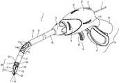
- FIG. 1Ais a perspective view of endoscopic surgical forceps exemplifying the aspects and features of the present disclosure, wherein the shaft of the endoscopic surgical forceps is disposed in a non-articulated position and wherein the jaw members of the endoscopic surgical forceps are disposed in a spaced-apart position;
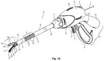
- FIG. 1Bis a perspective view of the endoscopic surgical forceps of FIG. 1A , wherein the shaft of the endoscopic surgical forceps is disposed in an articulated position and wherein the jaw members of the endoscopic surgical forceps are disposed in an approximated position;
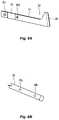
- FIGS. 1C and 1Dare enlarged schematic views of one embodiment of an engagement feature for coupling a knife blade to a knife drive rod exemplifying the aspects and features of the present disclosure
- FIGS. 2A and 2Bare enlarged schematic views of another embodiment of an engagement feature for coupling a knife blade to a knife drive rod exemplifying the aspects and features of the present disclosure
- FIG. 3is an enlarged schematic view of another embodiment of an engagement feature for coupling a knife blade to a knife drive rod exemplifying the aspects and features of the present disclosure
- FIG. 4is an enlarged schematic view of another embodiment of an engagement feature for coupling a knife blade to a knife drive rod exemplifying the aspects and features of the present disclosure
- FIGS. 5A and 5Bare enlarged schematic views of another embodiment of an engagement feature for coupling a knife blade chip to a knife drive rod exemplifying the aspects and features of the present disclosure
- FIG. 6is an enlarged schematic views of another embodiment of an engagement feature for coupling a knife blade chip to a knife drive rod exemplifying the aspects and features of the present disclosure
- FIG. 7is an enlarged schematic view of another embodiment of an engagement feature for coupling a knife blade to a knife drive rod exemplifying the aspects and features of the present disclosure.
- FIGS. 8A and 8Bare enlarged schematic views of another embodiment of an engagement feature for coupling a knife blade to a knife drive rod exemplifying the aspects and features of the present disclosure.
- an endoscopic surgical forcepsexemplifying the aspects and features of the present disclosure is shown generally identified by reference numeral 10 .
- endoscopic surgical forceps 10is generally described. Aspects and features of endoscopic surgical forceps 10 not germane to the understanding of the present disclosure are omitted to avoid obscuring the aspects and features of the present disclosure in unnecessary detail.
- Forceps 10includes a housing 20 , a handle assembly 30 , a trigger assembly 60 , a rotating assembly 70 , a plurality of articulation actuators 80 , an activation switch 4 , and an end effector assembly 100 .
- Forceps 10further includes a shaft 12 having a distal end 12 a configured to mechanically engage end effector assembly 100 and a proximal end 12 b that mechanically engages housing 20 .
- Forceps 10also includes cable 2 that connects forceps 10 to an energy source (not shown), e.g., a generator or other suitable power source, although forceps 10 may alternatively be configured as a battery-powered device.
- Cable 2includes a wire (or wires) (not shown) extending therethrough that has sufficient length to extend through shaft 12 in order to provide energy to one or both tissue-treating plates 114 , 124 of jaw members 110 , 120 , respectively, of end effector assembly 100 .
- Activation switch 4is coupled to tissue-treating plates 114 , 124 and the source of energy for selectively activating the supply of energy to jaw members 110 , 120 for treating, e.g., cauterizing, coagulating/desiccating, and/or sealing, tissue.
- Shaft 12 of forceps 10defines a distal segment 13 positioned towards distal end 12 a thereof, a proximal segment 14 positioned towards proximal end 12 b thereof, and an articulating section 15 disposed between the distal and proximal segments 13 , 14 , respectively.
- Articulating section 15includes a plurality of articulating links 16 having a plurality of articulation cables 17 extending therethrough. Each cable 17 is operably engaged at a distal end thereof to distal segment 13 and at a proximal end thereof to one of the articulation actuators 80 to enable articulation of distal segment 13 and, thus, end effector assembly 100 , relative to proximal segment 14 upon actuation of one or more of articulation actuators 80 .
- Rotating assembly 70operably couples shaft 12 to housing 20 to enable selective rotation of shaft 12 and, thus, end effector assembly 100 , relative to housing 20 .
- Handle assembly 30 of forceps 10includes a fixed handle 50 and a movable handle 40 .
- Fixed handle 50is integrally associated with housing 20 and handle 40 is movable relative to fixed handle 50 .
- Movable handle 40 of handle assembly 30is operably coupled to a drive assembly (not shown) that, together, mechanically cooperate to impart movement of one or both of jaw members 110 , 120 of end effector assembly 100 about a pivot 103 between a spaced-apart position ( FIG. 1A ) and an approximated position ( FIG. 1B ) to grasp tissue between jaw members 110 , 120 .
- FIG. 1Aspaced-apart position
- FIG. 1Bapproximated position
- movable handle 40is initially spaced-apart from fixed handle 50 and, correspondingly, jaw members 110 , 120 of end effector assembly 100 are disposed in the spaced-apart position. Movable handle 40 is compressible from this initial position to a compressed position corresponding to the approximated position of jaw members 110 , 120 ( FIG. 1B ).
- Trigger assembly 60includes a trigger 62 coupled to housing 20 and movable relative thereto between an un-actuated position and an actuated position.
- Trigger 62is operably coupled to a cutting mechanism 85 , various embodiments of which are detailed below, to actuate the cutting mechanism 85 to cut tissue grasped between jaw members 110 , 120 of end effector assembly 100 upon actuation of trigger 62 .
- a cutting mechanism 85various embodiments of which are detailed below, to actuate the cutting mechanism 85 to cut tissue grasped between jaw members 110 , 120 of end effector assembly 100 upon actuation of trigger 62 .
- a slide trigger, push-button, toggle switch, or other suitable actuatormay be provided.
- End effector assembly 100includes first and second jaw members 110 , 120 .
- Each jaw member 110 , 120includes a proximal flange portion 111 , 121 , an outer insulative jaw housing 112 , 122 disposed about the distal portion (not explicitly shown) of each jaw member 110 , 120 , and a tissue-treating plate 114 , 124 , respectively.
- Proximal flange portions 111 , 121are pivotably coupled to one another about pivot 103 for moving jaw members 110 , 120 between the spaced-apart and approximated positions, although other suitable mechanisms for pivoting jaw members 110 , 120 relative to one another are also contemplated.
- the distal portions (not explicitly shown) of the jaw members 110 , 120are configured to support jaw housings 112 , 122 , and tissue-treating plates 114 , 124 , respectively, thereon.
- Tissue-treating plates 114 , 124are formed from an electrically conductive material, e.g., for conducting electrical energy therebetween for treating tissue, although tissue-treating plates 114 , 124 may alternatively be configured to conduct any suitable energy, e.g., thermal, microwave, light, ultrasonic, etc., through tissue grasped therebetween for energy-based tissue treatment.
- tissue-treating plates 114 , 124are coupled to activation switch 4 and the source of energy (not shown), e.g., via the wires (not shown) extending from cable 2 through forceps 10 , such that energy may be selectively supplied to tissue-treating plate 114 and/or tissue-treating plate 124 and conducted therebetween and through tissue disposed between jaw members 110 , 120 to treat tissue.
- jaw members 110 , 120may further define a longitudinally-extending channel 125 (only the channel 125 of jaw member 120 is shown) for allowing reciprocation of the cutting mechanism 85 upon actuation of trigger 62 .
- Actuation of the trigger 62reciprocates a knife drive rod, e.g., knife drive rod 280 of FIG. 2B , operably coupled to the cutting mechanism, e.g., knife 285 .
- the knifee.g., knife 285 and knife drive rod, e.g., knife drive rod 280 , form a knife assembly 250 .
- Knife drive rod 280is made from a flexible material of sufficient strength to allow the knife drive rod 280 to both push and pull the knife 285 through tissue disposed between jaw members 110 , 120 . Moreover, the flexibility of the knife drive rod 280 allows the knife drive rod 280 to flex as needed during articulation of the jaw members 110 , 120 .
- the knife drive rod 280may be made from a variety of flexible materials that exhibit the necessary strength and flexibility to allow smooth translation of the knife drive rod 280 through one or more articulating joints of articulating section 15 such as: NiTiNOL, stainless Steel or high carbon steel, Inconel, Monel, Nimonic, Nitronic, Hastelloy (Nickel based alloys other than NiTiNOL), Elgiloy (Cobalt-Nickel), Brass, Phosphor Bronze, Beryllium Copper, Chrome-Vanadium or Chrome-Silicon, Titanium, and/or Braided Cable (i.e. Steel or Tungston).
- NiTiNOLstainless Steel or high carbon steel
- InconelMonel
- NimonicNitronic
- HastelloyNickel based alloys other than NiTiNOL
- ElgiloyCobalt-Nickel
- BrassPhosphor Bronze
- Beryllium CopperChrome-Vanadium or Chrome-Silicon
- Titaniumand
- the knife drive rod 280generally refers to a drive member that may be in the shape of a rod, cable, braided cable, tube, piece of sheet metal or plastic, screw and the like. It is envisioned that the term “rod” covers all of these and other commonly known types of drive members made from a variety of different materials so long as it is strong enough, durable enough and/or stiff enough to advance and retract the knife 285 .
- Knife 285is typically made from a stronger, harder, stiffer, and/or more durable material, e.g., stainless steel, to allow the knife 285 to easily translate through tissue on a repeated basis.
- Other materialsare also contemplated such as: Stainless Steel or High Carbon Steel, Tool Steel, High Speed Steel, Chrome Steel, Tungston Carbide, Titanium, Vanadium Alloys, Ceramic, Glass, and/or Plastic.
- a flexible wire or drive rode.g., drive rod 180 of FIG. 1D
- a knife 185needs to be used to push or pull a knife 185 .
- the length of the knife 185 attached to the drive rod 180should be minimized which will enhance usability and surgical access.
- the knife 185still needs to retract proximally enough to clear the tissue stop (not shown) of the jaw members 110 , 120 without retracting into any portion of the articulation section 15 .
- FIGS. 1C-8Bshow various retention mechanisms and methods of attaching a shorter knife 185 to the knife drive rod 180 .
- FIGS. 1C and 1Dshow an embodiment of the knife 185 for engagement to the knife drive rod 180 that minimizes dead space between the articulating section 15 and the jaw members 110 , 120 .
- knife 185includes a knife body 184 having a distal end 186 and a proximal end 182 , the distal end 186 including a sharpened edge for cutting tissue and the proximal end 182 including an aperture 187 defined therein for capturing the knife drive rod 180 .
- the knife 185 and knife drive rod 180form a knife assembly 150 .
- a pair of opposing capture tabs 181 a and 181 bare etched (or otherwise formed) from the proximal end 182 into the aperture 187 and are configured to capture and secure a tube 183 therebetween.
- the inner periphery of the tube 183is configured to engage, e.g., threadably engage, the knife drive rod 180 .
- the tube 183 and the knife drive rod 180may be welded, e.g., spot-welded, laser welded, inductively welded, bead welded, etc. or crimped after engagement within the tube 183 to provide additional engagement of the knife drive rod 180 therein.
- the knife drive rod 180 and the knife body 184are typically made from dissimilar materials and any such weld or bond may be weaker than desired. Thus, additional mechanical engagement between the two elements, e.g., the knife drive rod 180 and knife body 184 , is needed to prevent mechanical failure.
- Tube 183may be made from any type of metal, e.g., stainless steel, that will provide a secure weld to knife body 184 . In embodiments, the knife body 184 and the tube 183 are made from the same material, e.g., stainless steel, to assure a good weld. The tube 183 may also be welded to the knife 185 along the top and/or bottom length of the tube 183 .
- FIGS. 1C and 1Dshow the knife 185 extended beyond the attachment point. Only a necessary portion of the distal end 184 of the knife 185 projects beyond the connection to the knife drive rod 180 to minimize dead space. For a curved jaw design, this would ensure the attachment tube 183 and drive rod 180 do not enter the curved portion of the jaw members, 110 , 120 .
- FIGS. 2A-2Bshow another embodiment of a knife 285 for engagement to a knife drive rod 280 .
- knife 285includes a knife body 284 having a distal end 286 and a proximal end 282 , the distal end 286 including a sharpened edge for cutting tissue and the proximal end 282 including a slot 287 defined therein and configured to capture a tube 281 crimped, threaded or welded onto a portion of the knife drive rod 280 . Together the knife 285 and knife drive rod 280 form a knife assembly 250 .
- the knife drive rod 280needs to be flexible to accommodate articulation of the jaw members 110 , 120 , and the knife body 284 needs to be sufficiently strong to cut through tissue on a repeated basis
- the knife drive rod 280 and the knife body 284are typically made from dissimilar materials and any such weld or bond may be weaker than desired. Thus additional mechanical engagement between the two elements, e.g., the knife drive rod 280 and knife body 284 , is needed to prevent mechanical failure.
- Tube 281may be made from any type of metal, e.g., stainless steel, that will provide a secure weld to knife body 284 .
- the knife body 284 and the tube 281are made from the same material, e.g., stainless steel, to assure a good weld.
- the proximal end 282 of the knife body 280also includes an aperture 289 defined therein configured to receive the distal end 283 of the knife drive rod 280 . More particularly, the distal end 283 of the knife rod 280 is bent at an angle, e.g., 90°, such that during assembly the distal end 283 may be inserted into aperture 289 to secure the knife drive rod 280 to the knife body 284 .
- the tube 281is seated within slot 287 to capture the tube 281 therein and provide additional mechanical engagement between the knife drive rod 280 and the knife body 284 . Only a necessary portion of the distal end 284 of the knife 285 projects beyond the connection to the knife drive rod 280 to minimize dead space.
- FIG. 3shows another embodiment of a knife 385 for engagement to a knife drive rod 380 .
- knife 385includes a knife body 384 having a distal end 386 and a proximal end 382 , the distal end 386 including a sharpened edge for cutting tissue and the proximal end 382 configured to mechanically engage a tube 381 which may be crimped, threaded or welded onto the proximal end 382 along a lower edge 387 of the knife body 384 .
- the knife 385 and knife drive rod(not shown) form a knife assembly (not shown).
- Tube 381may be made from any type of metal, e.g., stainless steel, that will provide a secure weld to knife body 384 .
- the knife body 384 and the tube 381are made from the same material, e.g., stainless steel, to assure a good weld.
- the knife drive rodis secured within the tube 381 during assembly via crimping, welding, swaging or threadable engagement. Engaging the knife drive rod to the tube 381 which is secured to the lower edge 387 of the knife body 384 facilitates a more balanced actuation of the knife 385 during translation since the mechanical engagement of the knife body 384 and the tube 381 is along the centerline (lower edge 387 ) of the knife 385 .
- only a necessary portion of the distal end 384 of the knife 385projects beyond the connection to the knife drive rod to minimize dead space.
- the knife drive rod and/or the above described retention featuremay provide a width or depth to the knife 385 that may be utilized to facilitate retention of the knife 385 within the jaw members 110 , 120 or channel (not shown) defined within one or both jaw members 110 , 120 .
- FIG. 4shows another embodiment of a knife 485 for engagement to a knife drive rod 480 .
- knife 485includes a knife body 484 having a distal end 486 and a proximal end 482 , the distal end 486 including a sharpened edge for cutting tissue and the proximal end 482 including an aperture 487 defined therein for capturing the knife drive rod 480 .
- the knife 485 and knife drive rod 480form a knife assembly 450 .
- a series of fins 483are etched from the proximal end 482 into the aperture 487 that include one or more recessed portions (not shown) defined therein configured to partially receive the outer periphery of the knife drive rod 480 to mechanically capture the knife drive rod 480 on opposing sides along the length thereof.
- the knife drive rod 480is weaved through the various fins 483 to engage the recesses and secure the knife drive rod 480 to the knife 485 . Weaving the knife drive rod 480 through the fins 483 provides lateral stability to the knife 485 and knife drive rod 480 during use.
- a retention mechanisme.g., a cap 481
- a retention mechanisme.g., a cap 481
- a retention mechanisme.g., welded, swaged, crimped, etc.
- any other type of enlarged area at the distal endcan function as a retention mechanism, e.g., forged end, bubble-like end, additional pieces welded, crimped or swaged to end, etc.
- the dimensions of the cap 481are sized greater than the dimensions of the recesses to prevent slippage of the mechanical connection during use.
- the knife 485may be made from stainless steel, e.g., surgical stainless steel (316 SS) or other surgical metal, and the knife drive rod 480 may be made from Nitinol or other flexible metal or a metal hybrid (Nitinol inner rod and helical hollow strand HHS outer casing). Again, only a necessary portion of the distal end 484 of the knife 485 projects beyond the connection to the knife drive rod 480 to minimize dead space.
- stainless steele.g., surgical stainless steel (316 SS) or other surgical metal
- the knife drive rod 480may be made from Nitinol or other flexible metal or a metal hybrid (Nitinol inner rod and helical hollow strand HHS outer casing).
- FIGS. 5A and 5Bshow another embodiment of a knife 585 for engagement to a knife drive rod 580 .
- knife 585includes a knife body 584 having a distal end 586 and a proximal end 582 , the distal end 586 including a sharpened edge for cutting tissue and the proximal end 382 including lower edge 587 including an inner facing surface configured to engage the knife drive rod 580 via welding, or swaging along a weld 581 .
- Knife 585is generally chip-like as compared to the other knives, e.g., knife 285 , described herein and, in this particular embodiment, the knife 585 is welded directly to the knife drive rod 580 .
- the knife drive rod 580 and the knife body 584are typically made from dissimilar materials and any such weld or bond may be weaker than desired. Thus additional mechanical engagement between the two elements, e.g., the knife drive rod 580 and knife body 584 , may be needed to prevent mechanical failure. Any one of the aforementioned additional retention features may be implemented with chip-like knife 585 to produce a stronger engagement.
- the knife 585 and the knife drive rod 580may be made from the same type of material, e.g., stainless steel, that will provide a secure weld to knife body 584 .
- the knife drive rod 580may be seated within a recess (not shown) defined in a side of the knife 585 to at least partially capture the knife drive rod 580 therein and provide additional mechanical engagement between the knife drive rod 580 and the knife body 584 .
- FIG. 6shows another embodiment of a knife 685 for engagement to a knife drive rod 680 .
- knife 685includes a knife body 684 having a distal end 686 and a proximal end 682 , the distal end 686 including a sharpened edge for cutting tissue and the proximal end 682 including a rear edge 687 including an inner facing surface configured to engage the knife drive rod 680 via welding or swaging.
- Knife 685is generally chip-like similar to the embodiment shown in FIGS. 5A and 5B , and, in this particular embodiment, the proximal or rear edge of knife 685 is welded directly to the knife drive rod 680 .
- the knife drive rod 680may be seated within a recess (not shown) defined in the proximal or rear edge of the knife 685 to at least partially capture the knife drive rod 680 therein and provide additional mechanical engagement between the knife drive rod 680 and the knife body 684 .
- any one of the aforementioned additional retention featuresmay be implemented with chip-like knife 685 to produce a stronger engagement.
- the knife 685 and the knife drive rod 680may be made from the same type of material, e.g., stainless steel, that will provide a secure weld to knife body 684 .
- FIG. 7shows another embodiment of a knife 785 for engagement to a knife drive rod (not shown). More particularly, knife 785 includes a knife body 784 having a distal end 786 and a proximal end 782 , the distal end 786 including a sharpened edge for cutting tissue and the proximal end 782 including a series of retention tabs 783 that project generally laterally therefrom.
- the retention tabsmay be stamped or etched in the proximal end 782 and are configured to capture and secure the knife drive rod.
- the knife drive rod and the retention tabs 783may be welded, e.g., spot-welded, laser welded, or crimped after engagement to provide additional engagement of the knife drive rod to the knife 785 .
- the knife drive rod and the knife body 784are typically made from dissimilar materials and any such weld or bond may be weaker than desired. Thus additional mechanical engagement between the two elements, e.g., the knife drive rod and knife body 784 , may be needed to prevent mechanical failure.
- Retention tabs 783may be made from any type of metal that will provide a secure weld to knife drive rod.
- the knife body 784 and the knife drive rodare made from the same material, e.g., stainless steel, to assure a good weld.
- the retention tabs 783may be utilized to retain the knife 785 within a knife channel (not shown) defined within one or both jaw members 110 , 120 .
- the knife 785would be attached or otherwise engaged to the knife drive rod 780 by way of one or more of the retention features or retention methods described herein.
- the knife drive rod 780 and/or any of the above described retention featuresmay provide a width to the knife 785 that may be utilized to facilitate retention of the knife 785 within the jaw members 110 , 120 or channel (not shown) defined within one or both jaw members 110 , 120 .
- FIGS. 8A and 8Bshow another embodiment of a knife 885 for engagement to a knife drive rod 880 .
- knife 885includes a knife body 884 having a distal end 886 and a proximal end 882 , the distal end 886 including a sharpened edge for cutting tissue and the proximal end 882 including one or more detents 883 a , 883 b projecting therefrom configured to capture the knife drive rod 880 .
- the knife drive rod 880includes a corresponding one or more apertures 889 a , 889 b defined therein and configured to operably engage the detents 883 a , 883 b upon assembly.
- the knife drive rod 880may be welded, riveted, or swaged to the knife 885 .
- the detents 883 a , 883 bmay be spot-welded within the apertures 889 a , 889 b to further secure the knife drive rod 880 to the knife 885 .
- the detents 883 a , 883 b of the knife 885 and the knife drive rod 880may be made from any type of metal that will provide a secure weld. Since a majority of the extension and retraction forces associated with translating the knife 885 will be offloaded by the mechanical engagement of the detents 883 a , 883 b and apertures 889 a , 889 b , the additional weld would not necessarily need to be strong (unlike some of the aforedescribed embodiments). As such, the knife 885 and the knife drive rod 880 do not necessarily need to be made from the same type of material to insure a secure weld. Thus, a flexible super elastic material, e.g., Nitinol, may be used for the knife drive rod 880 and stainless steel may be utilized for the knife 885 .
- a flexible super elastic materiale.g., Nitinol
- the various embodiments disclosed hereinmay also be configured to work with robotic surgical systems and what is commonly referred to as “Telesurgery.”
- Such systemsemploy various robotic elements to assist the clinician and allow remote operation (or partial remote operation) of surgical instrumentation.
- Various robotic arms, gears, cams, pulleys, electric and mechanical motors, etc.may be employed for this purpose and may be designed with a robotic surgical system to assist the clinician during the course of an operation or treatment.
- Such robotic systemsmay include remotely steerable systems, automatically flexible surgical systems, remotely flexible surgical systems, remotely articulating surgical systems, wireless surgical systems, modular or selectively configurable remotely operated surgical systems, etc.
- the robotic surgical systemsmay be employed with one or more consoles that are next to the operating theater or located in a remote location.
- one team of cliniciansmay prep the patient for surgery and configure the robotic surgical system with one or more of the instruments disclosed herein while another clinician (or group of clinicians) remotely controls the instruments via the robotic surgical system.
- another clinicianor group of clinicians
- a highly skilled clinicianmay perform multiple operations in multiple locations without leaving his/her remote console which can be both economically advantageous and a benefit to the patient or a series of patients.
Landscapes
- Health & Medical Sciences (AREA)
- Surgery (AREA)
- Life Sciences & Earth Sciences (AREA)
- Engineering & Computer Science (AREA)
- Molecular Biology (AREA)
- Public Health (AREA)
- Heart & Thoracic Surgery (AREA)
- Medical Informatics (AREA)
- Nuclear Medicine, Radiotherapy & Molecular Imaging (AREA)
- Animal Behavior & Ethology (AREA)
- General Health & Medical Sciences (AREA)
- Biomedical Technology (AREA)
- Veterinary Medicine (AREA)
- Physics & Mathematics (AREA)
- Plasma & Fusion (AREA)
- Otolaryngology (AREA)
- Ophthalmology & Optometry (AREA)
- Surgical Instruments (AREA)
Abstract
Description
Claims (11)
Priority Applications (3)
| Application Number | Priority Date | Filing Date | Title |
|---|---|---|---|
| US16/832,886US11490917B2 (en) | 2019-03-29 | 2020-03-27 | Drive rod and knife blade for an articulating surgical instrument |
| US17/981,693US12171452B2 (en) | 2019-03-29 | 2022-11-07 | Drive rod and knife blade for an articulating surgical instrument |
| US18/946,662US20250064473A1 (en) | 2019-03-29 | 2024-11-13 | Drive rod and knife blade for an articulating surgical instrument |
Applications Claiming Priority (2)
| Application Number | Priority Date | Filing Date | Title |
|---|---|---|---|
| US201962825870P | 2019-03-29 | 2019-03-29 | |
| US16/832,886US11490917B2 (en) | 2019-03-29 | 2020-03-27 | Drive rod and knife blade for an articulating surgical instrument |
Related Child Applications (1)
| Application Number | Title | Priority Date | Filing Date |
|---|---|---|---|
| US17/981,693DivisionUS12171452B2 (en) | 2019-03-29 | 2022-11-07 | Drive rod and knife blade for an articulating surgical instrument |
Publications (2)
| Publication Number | Publication Date |
|---|---|
| US20200305915A1 US20200305915A1 (en) | 2020-10-01 |
| US11490917B2true US11490917B2 (en) | 2022-11-08 |
Family
ID=72606550
Family Applications (3)
| Application Number | Title | Priority Date | Filing Date |
|---|---|---|---|
| US16/832,886ActiveUS11490917B2 (en) | 2019-03-29 | 2020-03-27 | Drive rod and knife blade for an articulating surgical instrument |
| US17/981,693Active2040-07-05US12171452B2 (en) | 2019-03-29 | 2022-11-07 | Drive rod and knife blade for an articulating surgical instrument |
| US18/946,662PendingUS20250064473A1 (en) | 2019-03-29 | 2024-11-13 | Drive rod and knife blade for an articulating surgical instrument |
Family Applications After (2)
| Application Number | Title | Priority Date | Filing Date |
|---|---|---|---|
| US17/981,693Active2040-07-05US12171452B2 (en) | 2019-03-29 | 2022-11-07 | Drive rod and knife blade for an articulating surgical instrument |
| US18/946,662PendingUS20250064473A1 (en) | 2019-03-29 | 2024-11-13 | Drive rod and knife blade for an articulating surgical instrument |
Country Status (1)
| Country | Link |
|---|---|
| US (3) | US11490917B2 (en) |
Families Citing this family (2)
| Publication number | Priority date | Publication date | Assignee | Title |
|---|---|---|---|---|
| WO2023103969A1 (en)* | 2021-12-06 | 2023-06-15 | 深圳市精锋医疗科技股份有限公司 | Surgical instrument |
| US20240299079A1 (en)* | 2023-03-06 | 2024-09-12 | Cilag Gmbh International | Knife designs for end effectors used in surgical tools |
Citations (191)
| Publication number | Priority date | Publication date | Assignee | Title |
|---|---|---|---|---|
| SU401367A1 (en) | 1971-10-05 | 1973-10-12 | Тернопольский государственный медицинский институт | BIAKTIVNYE ELECTRO SURGICAL INSTRUMENT |
| DE2415263A1 (en) | 1974-03-29 | 1975-10-02 | Aesculap Werke Ag | Surgical H.F. coagulation probe has electrode tongs - with exposed ends of insulated conductors forming tong-jaws |
| DE2514501A1 (en) | 1975-04-03 | 1976-10-21 | Karl Storz | Bipolar coagulation instrument for endoscopes - has two high frequency electrodes looped over central insulating piece |
| DE2627679A1 (en) | 1975-06-26 | 1977-01-13 | Marcel Lamidey | HEMATISTIC HIGH FREQUENCY EXTRACTOR FORCEPS |
| USD249549S (en) | 1976-10-22 | 1978-09-19 | Aspen Laboratories, Inc. | Electrosurgical handle |
| USD263020S (en) | 1980-01-22 | 1982-02-16 | Rau Iii David M | Retractable knife |
| JPS61501068A (en) | 1984-01-30 | 1986-05-29 | ハルコフスキイ ナウチノ−イススレドワテルスキイ インスチチユ−ト オブスチエイ イ ネオトロジノイ ヒルルギイ | bipolar electrosurgical instrument |
| DE3423356C2 (en) | 1984-06-25 | 1986-06-26 | Berchtold Medizin-Elektronik GmbH & Co, 7200 Tuttlingen | Electrosurgical high frequency cutting instrument |
| DE3612646A1 (en) | 1985-04-16 | 1987-04-30 | Ellman International | Electrosurgical handle piece for blades, needles and forceps |
| DE3627221A1 (en) | 1986-01-15 | 1988-02-18 | Siemens Ag | HF SURGERY DEVICE WITH POWER CONTROL FROM THE SURGICAL HANDLE |
| DE8712328U1 (en) | 1987-09-11 | 1988-02-18 | Jakoubek, Franz, 7201 Emmingen-Liptingen | Endoscopy forceps |
| USD295894S (en) | 1985-09-26 | 1988-05-24 | Acme United Corporation | Disposable surgical scissors |
| USD295893S (en) | 1985-09-25 | 1988-05-24 | Acme United Corporation | Disposable surgical clamp |
| USD298353S (en) | 1986-05-06 | 1988-11-01 | Vitalmetrics, Inc. | Handle for surgical instrument |
| USD299413S (en) | 1985-07-17 | 1989-01-17 | The Stanley Works | Folding pocket saw handle |
| JPS6424051A (en) | 1987-07-16 | 1989-01-26 | Meisho Koki Kk | Sheet glass having transparency pattern and its production |
| JPH01147150A (en) | 1987-12-04 | 1989-06-08 | Hitachi Ltd | Variable venturi carburetor |
| JPH055106A (en) | 1990-07-31 | 1993-01-14 | Matsushita Electric Works Ltd | Production of alloy sintered body |
| JPH0540112A (en) | 1991-02-08 | 1993-02-19 | Tokico Ltd | Sample liquid component analyzer |
| USD343453S (en) | 1993-05-05 | 1994-01-18 | Laparomed Corporation | Handle for laparoscopic surgical instrument |
| JPH0630945B2 (en) | 1991-12-20 | 1994-04-27 | 株式会社サトー | Winding mechanism to prevent meandering of carbon ribbon |
| JPH06121797A (en) | 1992-02-27 | 1994-05-06 | United States Surgical Corp | Equipment and method for performing intracutaneous stapling of body tissue |
| USD348930S (en) | 1991-10-11 | 1994-07-19 | Ethicon, Inc. | Endoscopic stapler |
| USD349341S (en) | 1992-10-28 | 1994-08-02 | Microsurge, Inc. | Endoscopic grasper |
| JPH06285078A (en) | 1993-04-05 | 1994-10-11 | Olympus Optical Co Ltd | Forceps |
| JPH06343644A (en) | 1993-05-04 | 1994-12-20 | Gyrus Medical Ltd | Surgical peritoneoscope equipment |
| USD354564S (en) | 1993-06-25 | 1995-01-17 | Richard-Allan Medical Industries, Inc. | Surgical clip applier |
| DE4303882C2 (en) | 1993-02-10 | 1995-02-09 | Kernforschungsz Karlsruhe | Combination instrument for separation and coagulation for minimally invasive surgery |
| USD358887S (en) | 1993-12-02 | 1995-05-30 | Cobot Medical Corporation | Combined cutting and coagulating forceps |
| DE4403252A1 (en) | 1994-02-03 | 1995-08-10 | Michael Hauser | Instrument shaft for min. invasive surgery |
| JPH07265328A (en) | 1993-11-01 | 1995-10-17 | Gyrus Medical Ltd | Electrode assembly for electric surgery device and electric surgery device using it |
| JPH0856955A (en) | 1994-06-29 | 1996-03-05 | Gyrus Medical Ltd | Electric surgical apparatus |
| DE19515914C1 (en) | 1995-05-02 | 1996-07-25 | Aesculap Ag | Tong or scissor-shaped surgical instrument |
| DE19506363A1 (en) | 1995-02-24 | 1996-08-29 | Frost Lore Geb Haupt | Non-invasive thermometry in organs under hyperthermia and coagulation conditions |
| JPH08252263A (en) | 1994-12-21 | 1996-10-01 | Gyrus Medical Ltd | Electronic surgical incision instrument and electronic surgical incision device using the same |
| JPH08289895A (en) | 1995-04-21 | 1996-11-05 | Olympus Optical Co Ltd | Suture device |
| DE29616210U1 (en) | 1996-09-18 | 1996-11-14 | Olympus Winter & Ibe Gmbh, 22045 Hamburg | Handle for surgical instruments |
| JPH08317936A (en) | 1995-01-18 | 1996-12-03 | Ethicon Endo Surgery Inc | Hemostatic device for electric surgery provided with recessed type and/or crossed type electrode |
| JPH08317934A (en) | 1995-04-12 | 1996-12-03 | Ethicon Endo Surgery Inc | Hemostatic device for electric surgery with adaptable electrode |
| JPH09538A (en) | 1995-06-21 | 1997-01-07 | Fuji Photo Optical Co Ltd | High-frequency medical treatment instrument |
| JPH0910223A (en) | 1995-06-23 | 1997-01-14 | Gyrus Medical Ltd | Generator and system for electric operation |
| DE19608716C1 (en) | 1996-03-06 | 1997-04-17 | Aesculap Ag | Bipolar surgical holding instrument |
| JPH09122138A (en) | 1995-10-20 | 1997-05-13 | Ethicon Endo Surgery Inc | Apparatus for operation |
| USD384413S (en) | 1994-10-07 | 1997-09-30 | United States Surgical Corporation | Endoscopic suturing instrument |
| JPH10195A (en) | 1996-03-05 | 1998-01-06 | Ethicon Endo Surgery Inc | Surgical suturing machine with fixing mechanism |
| DE19751106A1 (en) | 1996-11-27 | 1998-05-28 | Eastman Kodak Co | Laser printer with array of laser diodes |
| JPH10155798A (en) | 1996-12-04 | 1998-06-16 | Asahi Optical Co Ltd | Hot biopsy forceps for endoscopes |
| USH1745H (en) | 1995-09-29 | 1998-08-04 | Paraschac; Joseph F. | Electrosurgical clamping device with insulation limited bipolar electrode |
| US5797941A (en)* | 1995-02-01 | 1998-08-25 | Ethicon Endo-Surgery, Inc. | Surgical instrument with expandable cutting element |
| USD402028S (en) | 1997-10-10 | 1998-12-01 | Invasatec, Inc. | Hand controller for medical system |
| JPH1147149A (en) | 1997-08-04 | 1999-02-23 | Olympus Optical Co Ltd | Endoscopic surgery appliance |
| JPH1170124A (en) | 1997-05-14 | 1999-03-16 | Ethicon Endo Surgery Inc | Improved electrosurgical hemostatic apparatus having anvil |
| USD408018S (en) | 1996-03-12 | 1999-04-13 | Mcnaughton Patrick J | Switch guard |
| DE19751108A1 (en) | 1997-11-18 | 1999-05-20 | Beger Frank Michael Dipl Desig | Electrosurgical operation tool, especially for diathermy |
| JPH11169381A (en) | 1997-12-15 | 1999-06-29 | Olympus Optical Co Ltd | High frequency treating device |
| JPH11192238A (en) | 1997-10-10 | 1999-07-21 | Ethicon Endo Surgery Inc | Ultrasonic forceps coagulation device improved of pivot-attaching of forceps arm |
| JPH11244298A (en) | 1997-12-19 | 1999-09-14 | Gyrus Medical Ltd | Electric surgical instrument |
| USD416089S (en) | 1996-04-08 | 1999-11-02 | Richard-Allan Medical Industries, Inc. | Endoscopic linear stapling and dividing surgical instrument |
| JP2000102545A (en) | 1997-06-18 | 2000-04-11 | Eggers & Associates Inc | Electric tweezers for surgery |
| USD424694S (en) | 1998-10-23 | 2000-05-09 | Sherwood Services Ag | Forceps |
| JP2000135222A (en) | 1998-08-27 | 2000-05-16 | Olympus Optical Co Ltd | High frequency treatment device |
| USD425201S (en) | 1998-10-23 | 2000-05-16 | Sherwood Services Ag | Disposable electrode assembly |
| WO2000036986A1 (en) | 1998-12-18 | 2000-06-29 | Karl Storz Gmbh & Co. Kg | Bipolar medical instrument |
| USH1904H (en) | 1997-05-14 | 2000-10-03 | Ethicon Endo-Surgery, Inc. | Electrosurgical hemostatic method and device |
| WO2000059392A1 (en) | 1999-04-01 | 2000-10-12 | Erbe Elektromedizin | Surgical instrument |
| JP2000342599A (en) | 1999-05-21 | 2000-12-12 | Gyrus Medical Ltd | Generator for electrosurgical operation, electrosurgical operation system, method for operating this system and method for performing amputation and resection of tissue by electrosurgical operation |
| JP2000350732A (en) | 1999-05-21 | 2000-12-19 | Gyrus Medical Ltd | Electrosurgical system, generator for electrosurgery, and method for cutting or excising tissue by electrosurgery |
| JP2001003400A (en) | 1999-06-21 | 2001-01-09 | Sumitomo Constr Mach Co Ltd | Monitor device for hydraulic shovel |
| JP2001008944A (en) | 1999-05-28 | 2001-01-16 | Gyrus Medical Ltd | Electric surgical signal generator and electric surgical system |
| JP2001029355A (en) | 1999-07-21 | 2001-02-06 | Olympus Optical Co Ltd | Electric cautery device |
| JP2001029356A (en) | 1999-06-11 | 2001-02-06 | Gyrus Medical Ltd | Electric and surgical signal generator |
| WO2001015614A1 (en) | 1999-08-27 | 2001-03-08 | Karl Storz Gmbh & Co. Kg | Bipolar medical instrument |
| JP2001128990A (en) | 1999-05-28 | 2001-05-15 | Gyrus Medical Ltd | Electro surgical instrument and electrosurgical tool converter |
| DE19946527C1 (en) | 1999-09-28 | 2001-07-12 | Storz Karl Gmbh & Co Kg | Bipolar, e.g. laparoscopic surgery instrument, cuts electrically, cauterizes and grips using simple design with high frequency current-concentrating projections |
| JP2001190564A (en) | 2000-01-12 | 2001-07-17 | Olympus Optical Co Ltd | Medical treatment instrument |
| WO2001054604A1 (en) | 2000-01-25 | 2001-08-02 | Aesculap Ag & Co. Kg | Bipolar gripping device |
| USD449886S1 (en) | 1998-10-23 | 2001-10-30 | Sherwood Services Ag | Forceps with disposable electrode |
| EP1159926A2 (en) | 2000-06-03 | 2001-12-05 | Aesculap Ag | Scissor- or forceps-like surgical instrument |
| USD453923S1 (en) | 2000-11-16 | 2002-02-26 | Carling Technologies, Inc. | Electrical rocker switch guard |
| USD454951S1 (en) | 2001-02-27 | 2002-03-26 | Visionary Biomedical, Inc. | Steerable catheter |
| DE20121161U1 (en) | 2001-01-31 | 2002-04-04 | Olympus Winter & Ibe Gmbh, 22045 Hamburg | Endoscopic instrument |
| JP2002136525A (en) | 2000-10-30 | 2002-05-14 | Olympus Optical Co Ltd | Surgical instrument |
| USD457958S1 (en) | 2001-04-06 | 2002-05-28 | Sherwood Services Ag | Vessel sealer and divider |
| USD457959S1 (en) | 2001-04-06 | 2002-05-28 | Sherwood Services Ag | Vessel sealer |
| WO2002045589A2 (en) | 2000-12-08 | 2002-06-13 | Gfd Gesellschaft Für Diamantprodukte Mbh | Instrument, which is provided for surgical applications and which comprises contact areas made of doped diamond, and method for cleaning the instrument |
| JP2002528166A (en) | 1998-10-23 | 2002-09-03 | シャーウッド サーヴィシス アクチェンゲゼルシャフト | Externally-opened vascular sealing forceps with disposable electrodes |
| DE10045375C2 (en) | 2000-09-14 | 2002-10-24 | Aesculap Ag & Co Kg | Medical instrument |
| USD465281S1 (en) | 1999-09-21 | 2002-11-05 | Karl Storz Gmbh & Co. Kg | Endoscopic medical instrument |
| USD466209S1 (en) | 2001-02-27 | 2002-11-26 | Visionary Biomedical, Inc. | Steerable catheter |
| EP1281878A1 (en) | 2001-08-02 | 2003-02-05 | Peugeot Citroen Automobiles | Pivot pin between two elements |
| JP2003116871A (en) | 2001-10-16 | 2003-04-22 | Olympus Optical Co Ltd | Surgical tool |
| JP2003175052A (en) | 2002-11-01 | 2003-06-24 | Olympus Optical Co Ltd | Coagulation treatment tool |
| JP2003245285A (en) | 2002-01-23 | 2003-09-02 | Ethicon Endo Surgery Inc | Feedback light apparatus and method for use with electrosurgical instrument |
| JP2004517668A (en) | 2000-10-20 | 2004-06-17 | オーナックス・メディカル・インコーポレーテッド | Surgical suturing instrument and method of use |
| USD493888S1 (en) | 2003-02-04 | 2004-08-03 | Sherwood Services Ag | Electrosurgical pencil with pistol grip |
| JP2004528869A (en) | 2001-01-26 | 2004-09-24 | エシコン・エンド−サージェリィ・インコーポレイテッド | Electrosurgical instruments for coagulation and cutting |
| USD496997S1 (en) | 2003-05-15 | 2004-10-05 | Sherwood Services Ag | Vessel sealer and divider |
| USD499181S1 (en) | 2003-05-15 | 2004-11-30 | Sherwood Services Ag | Handle for a vessel sealer and divider |
| USD502994S1 (en) | 2003-05-21 | 2005-03-15 | Blake, Iii Joseph W | Repeating multi-clip applier |
| JP2005152663A (en) | 2003-11-20 | 2005-06-16 | Sherwood Services Ag | Electrically conductive/insulative over-shoe for tissue fusion |
| USD509297S1 (en) | 2003-10-17 | 2005-09-06 | Tyco Healthcare Group, Lp | Surgical instrument |
| JP2005253789A (en) | 2004-03-12 | 2005-09-22 | Olympus Corp | Treatment instrument for operation |
| JP2005312807A (en) | 2004-04-30 | 2005-11-10 | Olympus Corp | Energy therapy device |
| WO2005110264A2 (en) | 2004-05-14 | 2005-11-24 | Erbe Elektromedizin Gmbh | Electrosurgical instrument |
| JP2006015078A (en) | 2004-07-05 | 2006-01-19 | Olympus Corp | Medical apparatus |
| JP2006501939A (en) | 2002-10-04 | 2006-01-19 | シャーウッド・サービシーズ・アクチェンゲゼルシャフト | Electrode assembly for sealing and cutting tissue and method for performing sealing and cutting tissue |
| WO2006021269A1 (en) | 2004-08-24 | 2006-03-02 | Erbe Elektromedizin Gmbh | Surgical instrument |
| JP2006095316A (en) | 2004-09-29 | 2006-04-13 | Sherwood Services Ag | Vessel sealer and divider having elongated knife stroke and safety for cutting mechanism |
| USD525361S1 (en) | 2004-10-06 | 2006-07-18 | Sherwood Services Ag | Hemostat style elongated dissecting and dividing instrument |
| USD531311S1 (en) | 2004-10-06 | 2006-10-31 | Sherwood Services Ag | Pistol grip style elongated dissecting and dividing instrument |
| USD533274S1 (en) | 2004-10-12 | 2006-12-05 | Allegiance Corporation | Handle for surgical suction-irrigation device |
| USD533942S1 (en) | 2004-06-30 | 2006-12-19 | Sherwood Services Ag | Open vessel sealer with mechanical cutter |
| USD535027S1 (en) | 2004-10-06 | 2007-01-09 | Sherwood Services Ag | Low profile vessel sealing and cutting mechanism |
| USD538932S1 (en) | 2005-06-30 | 2007-03-20 | Medical Action Industries Inc. | Surgical needle holder |
| USD541418S1 (en) | 2004-10-06 | 2007-04-24 | Sherwood Services Ag | Lung sealing device |
| USD541611S1 (en) | 2006-01-26 | 2007-05-01 | Robert Bosch Gmbh | Cordless screwdriver |
| USD541938S1 (en) | 2004-04-09 | 2007-05-01 | Sherwood Services Ag | Open vessel sealer with mechanical cutter |
| USD545432S1 (en) | 2003-08-08 | 2007-06-26 | Olympus Corporation | Distal portion of hemostatic forceps for endoscope |
| USD547154S1 (en) | 2006-09-08 | 2007-07-24 | Winsource Industries Limited | Rotary driving tool |
| DE202007009165U1 (en) | 2007-06-29 | 2007-08-30 | Kls Martin Gmbh + Co. Kg | Surgical instrument e.g. tube shaft, for use in e.g. high frequency coagulation instrument, has separator inserted through opening such that largest extension of opening transverse to moving direction corresponds to dimension of separator |
| DE202007009317U1 (en) | 2007-06-26 | 2007-08-30 | Aesculap Ag & Co. Kg | Surgical instrument |
| DE202007009318U1 (en) | 2007-06-26 | 2007-08-30 | Aesculap Ag & Co. Kg | Surgical instrument |
| DE10031773B4 (en) | 2000-05-04 | 2007-11-29 | Erbe Elektromedizin Gmbh | Surgical gripping instrument, in particular tweezers or forceps |
| DE202007016233U1 (en) | 2007-11-20 | 2008-01-31 | Aesculap Ag & Co. Kg | Surgical forceps |
| JP2008054926A (en) | 2006-08-31 | 2008-03-13 | Shiga Univ Of Medical Science | Microwave surgical device |
| USD564662S1 (en) | 2004-10-13 | 2008-03-18 | Sherwood Services Ag | Hourglass-shaped knife for electrosurgical forceps |
| WO2008040483A1 (en) | 2006-10-05 | 2008-04-10 | Erbe Elektromedizin Gmbh | Tubular shaft instrument |
| USD567943S1 (en) | 2004-10-08 | 2008-04-29 | Sherwood Services Ag | Over-ratchet safety for a vessel sealing instrument |
| USD575401S1 (en) | 2007-06-12 | 2008-08-19 | Tyco Healthcare Group Lp | Vessel sealer |
| USD575395S1 (en) | 2007-02-15 | 2008-08-19 | Tyco Healthcare Group Lp | Hemostat style elongated dissecting and dividing instrument |
| USD582038S1 (en) | 2004-10-13 | 2008-12-02 | Medtronic, Inc. | Transurethral needle ablation device |
| DE19738457B4 (en) | 1997-09-03 | 2009-01-02 | Celon Ag Medical Instruments | Method and device for in vivo deep coagulation of biological tissue volumes while sparing the tissue surface with high frequency alternating current |
| DE102008018406B3 (en) | 2008-04-10 | 2009-07-23 | Bowa-Electronic Gmbh & Co. Kg | Electrosurgical device |
| CN201299462Y (en) | 2008-10-28 | 2009-09-02 | 宋洪海 | Multi-layer metal composite pot |
| USD617901S1 (en) | 2009-05-13 | 2010-06-15 | Tyco Healthcare Group Lp | End effector chamfered tip |
| USD617902S1 (en) | 2009-05-13 | 2010-06-15 | Tyco Healthcare Group Lp | End effector tip with undercut top jaw |
| USD617900S1 (en) | 2009-05-13 | 2010-06-15 | Tyco Healthcare Group Lp | End effector tip with undercut bottom jaw |
| USD617903S1 (en) | 2009-05-13 | 2010-06-15 | Tyco Healthcare Group Lp | End effector pointed tip |
| USD618798S1 (en) | 2009-05-13 | 2010-06-29 | Tyco Healthcare Group Lp | Vessel sealing jaw seal plate |
| USD621503S1 (en) | 2009-04-28 | 2010-08-10 | Tyco Healthcare Group Ip | Pistol grip laparoscopic sealing and dissection device |
| USD627462S1 (en) | 2009-09-09 | 2010-11-16 | Tyco Healthcare Group Lp | Knife channel of a jaw device |
| USD628290S1 (en) | 2009-11-30 | 2010-11-30 | Tyco Healthcare Group Lp | Surgical instrument handle |
| USD628289S1 (en) | 2009-11-30 | 2010-11-30 | Tyco Healthcare Group Lp | Surgical instrument handle |
| USD630324S1 (en) | 2009-08-05 | 2011-01-04 | Tyco Healthcare Group Lp | Dissecting surgical jaw |
| WO2011018154A1 (en) | 2009-08-14 | 2011-02-17 | Erbe Elektromedizin Gmbh | Electrosurgical instrument |
| JP2011125195A (en) | 2009-12-14 | 2011-06-23 | Chugoku Electric Power Co Inc:The | Supporter for indirect hot-line work |
| USD649249S1 (en) | 2007-02-15 | 2011-11-22 | Tyco Healthcare Group Lp | End effectors of an elongated dissecting and dividing instrument |
| USD649643S1 (en) | 2009-05-13 | 2011-11-29 | Tyco Healthcare Group Lp | End effector with a rounded tip |
| USD661394S1 (en) | 2011-02-24 | 2012-06-05 | Tyco Healthcare Group Lp | Device jaw |
| USD670808S1 (en) | 2010-10-01 | 2012-11-13 | Tyco Healthcare Group Lp | Open vessel sealing forceps |
| US20130085516A1 (en)* | 2011-10-03 | 2013-04-04 | Tyco Healthcare Group Lp | Surgical Forceps |
| USD680220S1 (en) | 2012-01-12 | 2013-04-16 | Coviden IP | Slider handle for laparoscopic device |
| US20140221995A1 (en) | 2007-09-28 | 2014-08-07 | Covidien Lp | Dual durometer insulating boot for electrosurgical forceps |
| US20140221999A1 (en) | 2013-02-05 | 2014-08-07 | Covidien Lp | Electrosurgical forceps |
| US20140228842A1 (en) | 2003-06-13 | 2014-08-14 | Covidien Ag | Vessel sealer and divider for use with small trocars and cannulas |
| US20140230243A1 (en) | 2013-02-19 | 2014-08-21 | Covidien Lp | Method for manufacturing an electrode assembly configured for use with an electrosurigcal instrument |
| US20140236149A1 (en) | 2013-02-15 | 2014-08-21 | Covidien Lp | Electrosurgical forceps |
| US20140243824A1 (en) | 2010-08-23 | 2014-08-28 | Covidien Lp | Method of manufacturing tissue sealing electrodes |
| US20140243811A1 (en) | 2013-02-27 | 2014-08-28 | Covidien Lp | Limited use medical devices |
| US20140249528A1 (en)* | 2006-01-24 | 2014-09-04 | Covidien Lp | Vessel sealer and divider for large tissue structures |
| US20140257285A1 (en)* | 2013-03-11 | 2014-09-11 | Covidien Lp | Surgical instrument with switch activation control |
| US20140257274A1 (en) | 2013-03-11 | 2014-09-11 | Covidien Lp | Surgical instrument |
| US20140257284A1 (en) | 2013-03-11 | 2014-09-11 | Covidien Lp | Surgical instrument with system and method for springing open jaw members |
| US20140250686A1 (en) | 2011-07-11 | 2014-09-11 | Covidien Lp | Surgical forceps and method of manufacturing thereof |
| US20140257283A1 (en) | 2010-09-07 | 2014-09-11 | Covidien Lp | Electrosurgical instrument |
| US20140276803A1 (en) | 2013-03-12 | 2014-09-18 | Covidien Lp | Electrosurgical instrument with a knife blade stop |
| US20140288549A1 (en) | 2008-04-22 | 2014-09-25 | Covidien Lp | Jaw closure detection system |
| US20140288553A1 (en) | 2002-10-04 | 2014-09-25 | Covidien Ag | Vessel sealing instrument with electrical cutting mechanism |
| US20140284313A1 (en) | 2011-09-29 | 2014-09-25 | Covidien Lp | Surgical instrument shafts and methods of manufacturing shafts for surgical instruments |
| US20140330308A1 (en) | 2013-05-03 | 2014-11-06 | Covidien Lp | Endoscopic surgical forceps |
| US20140336635A1 (en) | 2013-05-10 | 2014-11-13 | Covidien Lp | Surgical forceps |
| US20140353188A1 (en) | 2013-06-04 | 2014-12-04 | Covidien Lp | Transportation integrity device for medical instruments |
| US20140364851A1 (en)* | 2013-06-06 | 2014-12-11 | Ethicon Endo-Surgery, Inc. | Surgical instrument having knife band with curved distal edge |
| US20150018816A1 (en) | 2013-07-11 | 2015-01-15 | Covidien Lp | Electrode assembly for use with surgical instruments |
| US20150025528A1 (en) | 2013-07-18 | 2015-01-22 | Covidien Lp | Surgical forceps for treating and cutting tissue |
| US20150032106A1 (en) | 2013-07-24 | 2015-01-29 | Covidien Lp | Vessel corset for use with electrosurgical forceps |
| US20150051640A1 (en) | 2013-08-13 | 2015-02-19 | Covidien Lp | Surgical instrument |
| US20150051598A1 (en) | 2013-08-13 | 2015-02-19 | Covidien Lp | Surgical forceps including thermal spread control |
| US20150066026A1 (en) | 2013-08-30 | 2015-03-05 | Covidien Lp | Switch assemblies for multi-function, energy-based surgical instruments |
| US20150080889A1 (en) | 2013-09-16 | 2015-03-19 | Covidien Lp | Split electrode for use in a bipolar electrosurgical instrument |
| US20150080880A1 (en) | 2013-09-16 | 2015-03-19 | Covidien Lp | Electrosurgical instrument with end-effector assembly including electrically-conductive, tissue-engaging surfaces and switchable bipolar electrodes |
| US20150088122A1 (en) | 2013-09-25 | 2015-03-26 | Covidien Lp | Devices, systems, and methods for grasping, treating, and dividing tissue |
| US20150088128A1 (en) | 2013-09-24 | 2015-03-26 | Covidien Lp | Electrode for use in a bipolar electrosurgical instrument |
| US20150082928A1 (en) | 2013-09-25 | 2015-03-26 | Covidien Lp | Multi-function surgical instruments |
| US20150088126A1 (en) | 2013-09-25 | 2015-03-26 | Covidien Lp | Wire retention unit for a surgical instrument |
| US20150094714A1 (en) | 2013-09-30 | 2015-04-02 | Covidien Lp | Limited-use medical device |
| US9084608B2 (en) | 2012-02-20 | 2015-07-21 | Covidien Lp | Knife deployment mechanisms for surgical forceps |
| US9211657B2 (en) | 2012-03-06 | 2015-12-15 | Covidien Lp | Surgical tissue sealer |
| JP6502328B2 (en) | 2013-09-26 | 2019-04-17 | ヴァレオ ビジョンValeo Vision | Eyeglass lens and eyeglass lens system |
| JP6511401B2 (en) | 2013-02-15 | 2019-05-15 | アラーガン、インコーポレイテッドAllergan,Incorporated | Sustained drug delivery implant |
| US10588651B2 (en)* | 2012-05-01 | 2020-03-17 | Covidien Lp | Surgical instrument with stamped double-flange jaws |
Family Cites Families (9)
| Publication number | Priority date | Publication date | Assignee | Title |
|---|---|---|---|---|
| JPS55106A (en) | 1978-05-01 | 1980-01-05 | Bii Uiriamusu Jiyun Kuraarensu | Kit for patient who artificial anus is formed |
| JPS6121797A (en) | 1984-07-09 | 1986-01-30 | Matsushita Electric Ind Co Ltd | How to operate a methane fermentation tank |
| JPS6285078A (en) | 1985-10-08 | 1987-04-18 | 池泉織物株式会社 | Modification treatment of silk fabric |
| JPH0826815B2 (en) | 1987-12-03 | 1996-03-21 | 株式会社ウオルブローフアーイースト | Vaporizer starting fuel supply device |
| JPH1024051A (en) | 1995-09-20 | 1998-01-27 | Olympus Optical Co Ltd | Coagulation forceps with separating function |
| JP3986127B2 (en) | 1997-08-06 | 2007-10-03 | オリンパス株式会社 | Endoscopic surgical instrument |
| JPH1192238A (en) | 1997-09-11 | 1999-04-06 | Asahi Glass Co Ltd | Method for producing alumina / zirconia / silica fused refractory |
| US20150297225A1 (en)* | 2014-04-16 | 2015-10-22 | Ethicon Endo-Surgery, Inc. | Fastener cartridges including extensions having different configurations |
| US10758229B2 (en)* | 2016-12-21 | 2020-09-01 | Ethicon Llc | Surgical instrument comprising improved jaw control |
- 2020
- 2020-03-27USUS16/832,886patent/US11490917B2/enactiveActive
- 2022
- 2022-11-07USUS17/981,693patent/US12171452B2/enactiveActive
- 2024
- 2024-11-13USUS18/946,662patent/US20250064473A1/enactivePending
Patent Citations (193)
| Publication number | Priority date | Publication date | Assignee | Title |
|---|---|---|---|---|
| SU401367A1 (en) | 1971-10-05 | 1973-10-12 | Тернопольский государственный медицинский институт | BIAKTIVNYE ELECTRO SURGICAL INSTRUMENT |
| DE2415263A1 (en) | 1974-03-29 | 1975-10-02 | Aesculap Werke Ag | Surgical H.F. coagulation probe has electrode tongs - with exposed ends of insulated conductors forming tong-jaws |
| DE2514501A1 (en) | 1975-04-03 | 1976-10-21 | Karl Storz | Bipolar coagulation instrument for endoscopes - has two high frequency electrodes looped over central insulating piece |
| DE2627679A1 (en) | 1975-06-26 | 1977-01-13 | Marcel Lamidey | HEMATISTIC HIGH FREQUENCY EXTRACTOR FORCEPS |
| USD249549S (en) | 1976-10-22 | 1978-09-19 | Aspen Laboratories, Inc. | Electrosurgical handle |
| USD263020S (en) | 1980-01-22 | 1982-02-16 | Rau Iii David M | Retractable knife |
| JPS61501068A (en) | 1984-01-30 | 1986-05-29 | ハルコフスキイ ナウチノ−イススレドワテルスキイ インスチチユ−ト オブスチエイ イ ネオトロジノイ ヒルルギイ | bipolar electrosurgical instrument |
| DE3423356C2 (en) | 1984-06-25 | 1986-06-26 | Berchtold Medizin-Elektronik GmbH & Co, 7200 Tuttlingen | Electrosurgical high frequency cutting instrument |
| DE3612646A1 (en) | 1985-04-16 | 1987-04-30 | Ellman International | Electrosurgical handle piece for blades, needles and forceps |
| USD299413S (en) | 1985-07-17 | 1989-01-17 | The Stanley Works | Folding pocket saw handle |
| USD295893S (en) | 1985-09-25 | 1988-05-24 | Acme United Corporation | Disposable surgical clamp |
| USD295894S (en) | 1985-09-26 | 1988-05-24 | Acme United Corporation | Disposable surgical scissors |
| DE3627221A1 (en) | 1986-01-15 | 1988-02-18 | Siemens Ag | HF SURGERY DEVICE WITH POWER CONTROL FROM THE SURGICAL HANDLE |
| USD298353S (en) | 1986-05-06 | 1988-11-01 | Vitalmetrics, Inc. | Handle for surgical instrument |
| JPS6424051A (en) | 1987-07-16 | 1989-01-26 | Meisho Koki Kk | Sheet glass having transparency pattern and its production |
| DE8712328U1 (en) | 1987-09-11 | 1988-02-18 | Jakoubek, Franz, 7201 Emmingen-Liptingen | Endoscopy forceps |
| JPH01147150A (en) | 1987-12-04 | 1989-06-08 | Hitachi Ltd | Variable venturi carburetor |
| JPH055106A (en) | 1990-07-31 | 1993-01-14 | Matsushita Electric Works Ltd | Production of alloy sintered body |
| JPH0540112A (en) | 1991-02-08 | 1993-02-19 | Tokico Ltd | Sample liquid component analyzer |
| USD348930S (en) | 1991-10-11 | 1994-07-19 | Ethicon, Inc. | Endoscopic stapler |
| JPH0630945B2 (en) | 1991-12-20 | 1994-04-27 | 株式会社サトー | Winding mechanism to prevent meandering of carbon ribbon |
| JPH06121797A (en) | 1992-02-27 | 1994-05-06 | United States Surgical Corp | Equipment and method for performing intracutaneous stapling of body tissue |
| USD349341S (en) | 1992-10-28 | 1994-08-02 | Microsurge, Inc. | Endoscopic grasper |
| DE4303882C2 (en) | 1993-02-10 | 1995-02-09 | Kernforschungsz Karlsruhe | Combination instrument for separation and coagulation for minimally invasive surgery |
| JPH06285078A (en) | 1993-04-05 | 1994-10-11 | Olympus Optical Co Ltd | Forceps |
| JPH06343644A (en) | 1993-05-04 | 1994-12-20 | Gyrus Medical Ltd | Surgical peritoneoscope equipment |
| USD343453S (en) | 1993-05-05 | 1994-01-18 | Laparomed Corporation | Handle for laparoscopic surgical instrument |
| USD354564S (en) | 1993-06-25 | 1995-01-17 | Richard-Allan Medical Industries, Inc. | Surgical clip applier |
| JPH07265328A (en) | 1993-11-01 | 1995-10-17 | Gyrus Medical Ltd | Electrode assembly for electric surgery device and electric surgery device using it |
| USD358887S (en) | 1993-12-02 | 1995-05-30 | Cobot Medical Corporation | Combined cutting and coagulating forceps |
| DE4403252A1 (en) | 1994-02-03 | 1995-08-10 | Michael Hauser | Instrument shaft for min. invasive surgery |
| JPH0856955A (en) | 1994-06-29 | 1996-03-05 | Gyrus Medical Ltd | Electric surgical apparatus |
| USD384413S (en) | 1994-10-07 | 1997-09-30 | United States Surgical Corporation | Endoscopic suturing instrument |
| JPH08252263A (en) | 1994-12-21 | 1996-10-01 | Gyrus Medical Ltd | Electronic surgical incision instrument and electronic surgical incision device using the same |
| JPH08317936A (en) | 1995-01-18 | 1996-12-03 | Ethicon Endo Surgery Inc | Hemostatic device for electric surgery provided with recessed type and/or crossed type electrode |
| US5797941A (en)* | 1995-02-01 | 1998-08-25 | Ethicon Endo-Surgery, Inc. | Surgical instrument with expandable cutting element |
| DE19506363A1 (en) | 1995-02-24 | 1996-08-29 | Frost Lore Geb Haupt | Non-invasive thermometry in organs under hyperthermia and coagulation conditions |
| JPH08317934A (en) | 1995-04-12 | 1996-12-03 | Ethicon Endo Surgery Inc | Hemostatic device for electric surgery with adaptable electrode |
| JPH08289895A (en) | 1995-04-21 | 1996-11-05 | Olympus Optical Co Ltd | Suture device |
| DE19515914C1 (en) | 1995-05-02 | 1996-07-25 | Aesculap Ag | Tong or scissor-shaped surgical instrument |
| JPH09538A (en) | 1995-06-21 | 1997-01-07 | Fuji Photo Optical Co Ltd | High-frequency medical treatment instrument |
| JPH0910223A (en) | 1995-06-23 | 1997-01-14 | Gyrus Medical Ltd | Generator and system for electric operation |
| USH1745H (en) | 1995-09-29 | 1998-08-04 | Paraschac; Joseph F. | Electrosurgical clamping device with insulation limited bipolar electrode |
| JPH09122138A (en) | 1995-10-20 | 1997-05-13 | Ethicon Endo Surgery Inc | Apparatus for operation |
| JPH10195A (en) | 1996-03-05 | 1998-01-06 | Ethicon Endo Surgery Inc | Surgical suturing machine with fixing mechanism |
| DE19608716C1 (en) | 1996-03-06 | 1997-04-17 | Aesculap Ag | Bipolar surgical holding instrument |
| USD408018S (en) | 1996-03-12 | 1999-04-13 | Mcnaughton Patrick J | Switch guard |
| USD416089S (en) | 1996-04-08 | 1999-11-02 | Richard-Allan Medical Industries, Inc. | Endoscopic linear stapling and dividing surgical instrument |
| DE29616210U1 (en) | 1996-09-18 | 1996-11-14 | Olympus Winter & Ibe Gmbh, 22045 Hamburg | Handle for surgical instruments |
| DE19751106A1 (en) | 1996-11-27 | 1998-05-28 | Eastman Kodak Co | Laser printer with array of laser diodes |
| JPH10155798A (en) | 1996-12-04 | 1998-06-16 | Asahi Optical Co Ltd | Hot biopsy forceps for endoscopes |
| USH2037H1 (en) | 1997-05-14 | 2002-07-02 | David C. Yates | Electrosurgical hemostatic device including an anvil |
| JPH1170124A (en) | 1997-05-14 | 1999-03-16 | Ethicon Endo Surgery Inc | Improved electrosurgical hemostatic apparatus having anvil |
| USH1904H (en) | 1997-05-14 | 2000-10-03 | Ethicon Endo-Surgery, Inc. | Electrosurgical hemostatic method and device |
| JP2000102545A (en) | 1997-06-18 | 2000-04-11 | Eggers & Associates Inc | Electric tweezers for surgery |
| JPH1147149A (en) | 1997-08-04 | 1999-02-23 | Olympus Optical Co Ltd | Endoscopic surgery appliance |
| DE19738457B4 (en) | 1997-09-03 | 2009-01-02 | Celon Ag Medical Instruments | Method and device for in vivo deep coagulation of biological tissue volumes while sparing the tissue surface with high frequency alternating current |
| JPH11192238A (en) | 1997-10-10 | 1999-07-21 | Ethicon Endo Surgery Inc | Ultrasonic forceps coagulation device improved of pivot-attaching of forceps arm |
| USD402028S (en) | 1997-10-10 | 1998-12-01 | Invasatec, Inc. | Hand controller for medical system |
| DE19751108A1 (en) | 1997-11-18 | 1999-05-20 | Beger Frank Michael Dipl Desig | Electrosurgical operation tool, especially for diathermy |
| JPH11169381A (en) | 1997-12-15 | 1999-06-29 | Olympus Optical Co Ltd | High frequency treating device |
| JPH11244298A (en) | 1997-12-19 | 1999-09-14 | Gyrus Medical Ltd | Electric surgical instrument |
| JP2000135222A (en) | 1998-08-27 | 2000-05-16 | Olympus Optical Co Ltd | High frequency treatment device |
| USD424694S (en) | 1998-10-23 | 2000-05-09 | Sherwood Services Ag | Forceps |
| USD425201S (en) | 1998-10-23 | 2000-05-16 | Sherwood Services Ag | Disposable electrode assembly |
| USD449886S1 (en) | 1998-10-23 | 2001-10-30 | Sherwood Services Ag | Forceps with disposable electrode |
| JP2002528166A (en) | 1998-10-23 | 2002-09-03 | シャーウッド サーヴィシス アクチェンゲゼルシャフト | Externally-opened vascular sealing forceps with disposable electrodes |
| WO2000036986A1 (en) | 1998-12-18 | 2000-06-29 | Karl Storz Gmbh & Co. Kg | Bipolar medical instrument |
| WO2000059392A1 (en) | 1999-04-01 | 2000-10-12 | Erbe Elektromedizin | Surgical instrument |
| JP2000350732A (en) | 1999-05-21 | 2000-12-19 | Gyrus Medical Ltd | Electrosurgical system, generator for electrosurgery, and method for cutting or excising tissue by electrosurgery |
| JP2000342599A (en) | 1999-05-21 | 2000-12-12 | Gyrus Medical Ltd | Generator for electrosurgical operation, electrosurgical operation system, method for operating this system and method for performing amputation and resection of tissue by electrosurgical operation |
| JP2001008944A (en) | 1999-05-28 | 2001-01-16 | Gyrus Medical Ltd | Electric surgical signal generator and electric surgical system |
| JP2001128990A (en) | 1999-05-28 | 2001-05-15 | Gyrus Medical Ltd | Electro surgical instrument and electrosurgical tool converter |
| JP2001029356A (en) | 1999-06-11 | 2001-02-06 | Gyrus Medical Ltd | Electric and surgical signal generator |
| JP2001003400A (en) | 1999-06-21 | 2001-01-09 | Sumitomo Constr Mach Co Ltd | Monitor device for hydraulic shovel |
| JP2001029355A (en) | 1999-07-21 | 2001-02-06 | Olympus Optical Co Ltd | Electric cautery device |
| WO2001015614A1 (en) | 1999-08-27 | 2001-03-08 | Karl Storz Gmbh & Co. Kg | Bipolar medical instrument |
| USD465281S1 (en) | 1999-09-21 | 2002-11-05 | Karl Storz Gmbh & Co. Kg | Endoscopic medical instrument |
| DE19946527C1 (en) | 1999-09-28 | 2001-07-12 | Storz Karl Gmbh & Co Kg | Bipolar, e.g. laparoscopic surgery instrument, cuts electrically, cauterizes and grips using simple design with high frequency current-concentrating projections |
| JP2001190564A (en) | 2000-01-12 | 2001-07-17 | Olympus Optical Co Ltd | Medical treatment instrument |
| WO2001054604A1 (en) | 2000-01-25 | 2001-08-02 | Aesculap Ag & Co. Kg | Bipolar gripping device |
| DE10031773B4 (en) | 2000-05-04 | 2007-11-29 | Erbe Elektromedizin Gmbh | Surgical gripping instrument, in particular tweezers or forceps |
| EP1159926A2 (en) | 2000-06-03 | 2001-12-05 | Aesculap Ag | Scissor- or forceps-like surgical instrument |
| DE10045375C2 (en) | 2000-09-14 | 2002-10-24 | Aesculap Ag & Co Kg | Medical instrument |
| JP2004517668A (en) | 2000-10-20 | 2004-06-17 | オーナックス・メディカル・インコーポレーテッド | Surgical suturing instrument and method of use |
| JP2002136525A (en) | 2000-10-30 | 2002-05-14 | Olympus Optical Co Ltd | Surgical instrument |
| USD453923S1 (en) | 2000-11-16 | 2002-02-26 | Carling Technologies, Inc. | Electrical rocker switch guard |
| WO2002045589A2 (en) | 2000-12-08 | 2002-06-13 | Gfd Gesellschaft Für Diamantprodukte Mbh | Instrument, which is provided for surgical applications and which comprises contact areas made of doped diamond, and method for cleaning the instrument |
| JP2004528869A (en) | 2001-01-26 | 2004-09-24 | エシコン・エンド−サージェリィ・インコーポレイテッド | Electrosurgical instruments for coagulation and cutting |
| DE20121161U1 (en) | 2001-01-31 | 2002-04-04 | Olympus Winter & Ibe Gmbh, 22045 Hamburg | Endoscopic instrument |
| USD466209S1 (en) | 2001-02-27 | 2002-11-26 | Visionary Biomedical, Inc. | Steerable catheter |
| USD454951S1 (en) | 2001-02-27 | 2002-03-26 | Visionary Biomedical, Inc. | Steerable catheter |
| USD457959S1 (en) | 2001-04-06 | 2002-05-28 | Sherwood Services Ag | Vessel sealer |
| USD457958S1 (en) | 2001-04-06 | 2002-05-28 | Sherwood Services Ag | Vessel sealer and divider |
| EP1281878A1 (en) | 2001-08-02 | 2003-02-05 | Peugeot Citroen Automobiles | Pivot pin between two elements |
| JP2003116871A (en) | 2001-10-16 | 2003-04-22 | Olympus Optical Co Ltd | Surgical tool |
| JP2003245285A (en) | 2002-01-23 | 2003-09-02 | Ethicon Endo Surgery Inc | Feedback light apparatus and method for use with electrosurgical instrument |
| US20140288553A1 (en) | 2002-10-04 | 2014-09-25 | Covidien Ag | Vessel sealing instrument with electrical cutting mechanism |
| JP2006501939A (en) | 2002-10-04 | 2006-01-19 | シャーウッド・サービシーズ・アクチェンゲゼルシャフト | Electrode assembly for sealing and cutting tissue and method for performing sealing and cutting tissue |
| JP2003175052A (en) | 2002-11-01 | 2003-06-24 | Olympus Optical Co Ltd | Coagulation treatment tool |
| USD493888S1 (en) | 2003-02-04 | 2004-08-03 | Sherwood Services Ag | Electrosurgical pencil with pistol grip |
| USD496997S1 (en) | 2003-05-15 | 2004-10-05 | Sherwood Services Ag | Vessel sealer and divider |
| USD499181S1 (en) | 2003-05-15 | 2004-11-30 | Sherwood Services Ag | Handle for a vessel sealer and divider |
| USD502994S1 (en) | 2003-05-21 | 2005-03-15 | Blake, Iii Joseph W | Repeating multi-clip applier |
| US20140228842A1 (en) | 2003-06-13 | 2014-08-14 | Covidien Ag | Vessel sealer and divider for use with small trocars and cannulas |
| USD545432S1 (en) | 2003-08-08 | 2007-06-26 | Olympus Corporation | Distal portion of hemostatic forceps for endoscope |
| USD509297S1 (en) | 2003-10-17 | 2005-09-06 | Tyco Healthcare Group, Lp | Surgical instrument |
| JP2005152663A (en) | 2003-11-20 | 2005-06-16 | Sherwood Services Ag | Electrically conductive/insulative over-shoe for tissue fusion |
| JP2005253789A (en) | 2004-03-12 | 2005-09-22 | Olympus Corp | Treatment instrument for operation |
| USD541938S1 (en) | 2004-04-09 | 2007-05-01 | Sherwood Services Ag | Open vessel sealer with mechanical cutter |
| JP2005312807A (en) | 2004-04-30 | 2005-11-10 | Olympus Corp | Energy therapy device |
| WO2005110264A2 (en) | 2004-05-14 | 2005-11-24 | Erbe Elektromedizin Gmbh | Electrosurgical instrument |
| DE102004026179B4 (en) | 2004-05-14 | 2009-01-22 | Erbe Elektromedizin Gmbh | Electrosurgical instrument |
| USD533942S1 (en) | 2004-06-30 | 2006-12-19 | Sherwood Services Ag | Open vessel sealer with mechanical cutter |
| JP2006015078A (en) | 2004-07-05 | 2006-01-19 | Olympus Corp | Medical apparatus |
| WO2006021269A1 (en) | 2004-08-24 | 2006-03-02 | Erbe Elektromedizin Gmbh | Surgical instrument |
| JP2006095316A (en) | 2004-09-29 | 2006-04-13 | Sherwood Services Ag | Vessel sealer and divider having elongated knife stroke and safety for cutting mechanism |
| USD541418S1 (en) | 2004-10-06 | 2007-04-24 | Sherwood Services Ag | Lung sealing device |
| USD535027S1 (en) | 2004-10-06 | 2007-01-09 | Sherwood Services Ag | Low profile vessel sealing and cutting mechanism |
| USD531311S1 (en) | 2004-10-06 | 2006-10-31 | Sherwood Services Ag | Pistol grip style elongated dissecting and dividing instrument |
| USD525361S1 (en) | 2004-10-06 | 2006-07-18 | Sherwood Services Ag | Hemostat style elongated dissecting and dividing instrument |
| USD567943S1 (en) | 2004-10-08 | 2008-04-29 | Sherwood Services Ag | Over-ratchet safety for a vessel sealing instrument |
| USD533274S1 (en) | 2004-10-12 | 2006-12-05 | Allegiance Corporation | Handle for surgical suction-irrigation device |
| USD564662S1 (en) | 2004-10-13 | 2008-03-18 | Sherwood Services Ag | Hourglass-shaped knife for electrosurgical forceps |
| USD582038S1 (en) | 2004-10-13 | 2008-12-02 | Medtronic, Inc. | Transurethral needle ablation device |
| USD538932S1 (en) | 2005-06-30 | 2007-03-20 | Medical Action Industries Inc. | Surgical needle holder |
| US20140249528A1 (en)* | 2006-01-24 | 2014-09-04 | Covidien Lp | Vessel sealer and divider for large tissue structures |
| USD541611S1 (en) | 2006-01-26 | 2007-05-01 | Robert Bosch Gmbh | Cordless screwdriver |
| JP2008054926A (en) | 2006-08-31 | 2008-03-13 | Shiga Univ Of Medical Science | Microwave surgical device |
| USD547154S1 (en) | 2006-09-08 | 2007-07-24 | Winsource Industries Limited | Rotary driving tool |
| WO2008040483A1 (en) | 2006-10-05 | 2008-04-10 | Erbe Elektromedizin Gmbh | Tubular shaft instrument |
| USD575395S1 (en) | 2007-02-15 | 2008-08-19 | Tyco Healthcare Group Lp | Hemostat style elongated dissecting and dividing instrument |
| USD649249S1 (en) | 2007-02-15 | 2011-11-22 | Tyco Healthcare Group Lp | End effectors of an elongated dissecting and dividing instrument |
| USD575401S1 (en) | 2007-06-12 | 2008-08-19 | Tyco Healthcare Group Lp | Vessel sealer |
| DE202007009318U1 (en) | 2007-06-26 | 2007-08-30 | Aesculap Ag & Co. Kg | Surgical instrument |
| DE202007009317U1 (en) | 2007-06-26 | 2007-08-30 | Aesculap Ag & Co. Kg | Surgical instrument |
| DE202007009165U1 (en) | 2007-06-29 | 2007-08-30 | Kls Martin Gmbh + Co. Kg | Surgical instrument e.g. tube shaft, for use in e.g. high frequency coagulation instrument, has separator inserted through opening such that largest extension of opening transverse to moving direction corresponds to dimension of separator |
| US20140221995A1 (en) | 2007-09-28 | 2014-08-07 | Covidien Lp | Dual durometer insulating boot for electrosurgical forceps |
| DE202007016233U1 (en) | 2007-11-20 | 2008-01-31 | Aesculap Ag & Co. Kg | Surgical forceps |
| DE102008018406B3 (en) | 2008-04-10 | 2009-07-23 | Bowa-Electronic Gmbh & Co. Kg | Electrosurgical device |
| US20140288549A1 (en) | 2008-04-22 | 2014-09-25 | Covidien Lp | Jaw closure detection system |
| CN201299462Y (en) | 2008-10-28 | 2009-09-02 | 宋洪海 | Multi-layer metal composite pot |
| USD621503S1 (en) | 2009-04-28 | 2010-08-10 | Tyco Healthcare Group Ip | Pistol grip laparoscopic sealing and dissection device |
| USD618798S1 (en) | 2009-05-13 | 2010-06-29 | Tyco Healthcare Group Lp | Vessel sealing jaw seal plate |
| USD617903S1 (en) | 2009-05-13 | 2010-06-15 | Tyco Healthcare Group Lp | End effector pointed tip |
| USD617900S1 (en) | 2009-05-13 | 2010-06-15 | Tyco Healthcare Group Lp | End effector tip with undercut bottom jaw |
| USD617902S1 (en) | 2009-05-13 | 2010-06-15 | Tyco Healthcare Group Lp | End effector tip with undercut top jaw |
| USD617901S1 (en) | 2009-05-13 | 2010-06-15 | Tyco Healthcare Group Lp | End effector chamfered tip |
| USD649643S1 (en) | 2009-05-13 | 2011-11-29 | Tyco Healthcare Group Lp | End effector with a rounded tip |
| USD630324S1 (en) | 2009-08-05 | 2011-01-04 | Tyco Healthcare Group Lp | Dissecting surgical jaw |
| WO2011018154A1 (en) | 2009-08-14 | 2011-02-17 | Erbe Elektromedizin Gmbh | Electrosurgical instrument |
| USD627462S1 (en) | 2009-09-09 | 2010-11-16 | Tyco Healthcare Group Lp | Knife channel of a jaw device |
| USD628290S1 (en) | 2009-11-30 | 2010-11-30 | Tyco Healthcare Group Lp | Surgical instrument handle |
| USD628289S1 (en) | 2009-11-30 | 2010-11-30 | Tyco Healthcare Group Lp | Surgical instrument handle |
| JP2011125195A (en) | 2009-12-14 | 2011-06-23 | Chugoku Electric Power Co Inc:The | Supporter for indirect hot-line work |
| US20140243824A1 (en) | 2010-08-23 | 2014-08-28 | Covidien Lp | Method of manufacturing tissue sealing electrodes |
| US20140257283A1 (en) | 2010-09-07 | 2014-09-11 | Covidien Lp | Electrosurgical instrument |
| USD670808S1 (en) | 2010-10-01 | 2012-11-13 | Tyco Healthcare Group Lp | Open vessel sealing forceps |
| USD661394S1 (en) | 2011-02-24 | 2012-06-05 | Tyco Healthcare Group Lp | Device jaw |
| US20140250686A1 (en) | 2011-07-11 | 2014-09-11 | Covidien Lp | Surgical forceps and method of manufacturing thereof |
| US20140284313A1 (en) | 2011-09-29 | 2014-09-25 | Covidien Lp | Surgical instrument shafts and methods of manufacturing shafts for surgical instruments |
| US20130085516A1 (en)* | 2011-10-03 | 2013-04-04 | Tyco Healthcare Group Lp | Surgical Forceps |
| USD680220S1 (en) | 2012-01-12 | 2013-04-16 | Coviden IP | Slider handle for laparoscopic device |
| US9084608B2 (en) | 2012-02-20 | 2015-07-21 | Covidien Lp | Knife deployment mechanisms for surgical forceps |
| US9211657B2 (en) | 2012-03-06 | 2015-12-15 | Covidien Lp | Surgical tissue sealer |
| US10588651B2 (en)* | 2012-05-01 | 2020-03-17 | Covidien Lp | Surgical instrument with stamped double-flange jaws |
| US20140221999A1 (en) | 2013-02-05 | 2014-08-07 | Covidien Lp | Electrosurgical forceps |
| JP6511401B2 (en) | 2013-02-15 | 2019-05-15 | アラーガン、インコーポレイテッドAllergan,Incorporated | Sustained drug delivery implant |
| US20140236149A1 (en) | 2013-02-15 | 2014-08-21 | Covidien Lp | Electrosurgical forceps |
| US20140230243A1 (en) | 2013-02-19 | 2014-08-21 | Covidien Lp | Method for manufacturing an electrode assembly configured for use with an electrosurigcal instrument |
| US20140243811A1 (en) | 2013-02-27 | 2014-08-28 | Covidien Lp | Limited use medical devices |
| US20140257284A1 (en) | 2013-03-11 | 2014-09-11 | Covidien Lp | Surgical instrument with system and method for springing open jaw members |
| US20140257274A1 (en) | 2013-03-11 | 2014-09-11 | Covidien Lp | Surgical instrument |
| US20140257285A1 (en)* | 2013-03-11 | 2014-09-11 | Covidien Lp | Surgical instrument with switch activation control |
| US20140276803A1 (en) | 2013-03-12 | 2014-09-18 | Covidien Lp | Electrosurgical instrument with a knife blade stop |
| US20140330308A1 (en) | 2013-05-03 | 2014-11-06 | Covidien Lp | Endoscopic surgical forceps |
| US20140336635A1 (en) | 2013-05-10 | 2014-11-13 | Covidien Lp | Surgical forceps |
| US20140353188A1 (en) | 2013-06-04 | 2014-12-04 | Covidien Lp | Transportation integrity device for medical instruments |
| US20140364851A1 (en)* | 2013-06-06 | 2014-12-11 | Ethicon Endo-Surgery, Inc. | Surgical instrument having knife band with curved distal edge |
| US20150018816A1 (en) | 2013-07-11 | 2015-01-15 | Covidien Lp | Electrode assembly for use with surgical instruments |
| US20150025528A1 (en) | 2013-07-18 | 2015-01-22 | Covidien Lp | Surgical forceps for treating and cutting tissue |
| US20150032106A1 (en) | 2013-07-24 | 2015-01-29 | Covidien Lp | Vessel corset for use with electrosurgical forceps |
| US20150051640A1 (en) | 2013-08-13 | 2015-02-19 | Covidien Lp | Surgical instrument |
| US20150051598A1 (en) | 2013-08-13 | 2015-02-19 | Covidien Lp | Surgical forceps including thermal spread control |
| US20150066026A1 (en) | 2013-08-30 | 2015-03-05 | Covidien Lp | Switch assemblies for multi-function, energy-based surgical instruments |
| US20150080880A1 (en) | 2013-09-16 | 2015-03-19 | Covidien Lp | Electrosurgical instrument with end-effector assembly including electrically-conductive, tissue-engaging surfaces and switchable bipolar electrodes |
| US20150080889A1 (en) | 2013-09-16 | 2015-03-19 | Covidien Lp | Split electrode for use in a bipolar electrosurgical instrument |
| US20150088128A1 (en) | 2013-09-24 | 2015-03-26 | Covidien Lp | Electrode for use in a bipolar electrosurgical instrument |
| US20150082928A1 (en) | 2013-09-25 | 2015-03-26 | Covidien Lp | Multi-function surgical instruments |
| US20150088126A1 (en) | 2013-09-25 | 2015-03-26 | Covidien Lp | Wire retention unit for a surgical instrument |
| US20150088122A1 (en) | 2013-09-25 | 2015-03-26 | Covidien Lp | Devices, systems, and methods for grasping, treating, and dividing tissue |
| JP6502328B2 (en) | 2013-09-26 | 2019-04-17 | ヴァレオ ビジョンValeo Vision | Eyeglass lens and eyeglass lens system |
| US20150094714A1 (en) | 2013-09-30 | 2015-04-02 | Covidien Lp | Limited-use medical device |
Non-Patent Citations (51)
| Title |
|---|
| "Electrosurgery: A Historical Overview" Innovations in Electrosurgery; Sales/Product Literature; Dec. 31, 2000. (6 pages). |
| "Reducing Needlestick Injuries in the Operating Room" Sales/Product Literature 2001. (1 page). |
| Barbara Levy, "Use of a New Vessel Ligation Device During Vaginal Hysterectomy" FIGO 2000, Washington, D.C.. (1 page). |
| Benaron et al., "Optical Time-Of-Flight and Absorbance Imaging of Biologic Media", Science, American Association for the Advancement of Science, Washington, DC, vol. 259, Mar. 5, 1993, pp. 1463-1466. |
| Bergdahl et al. "Studies on Coagulation and the Development of an Automatic Computerized Bipolar Coagulator" J. Neurosurg, vol. 75, Jul. 1991, pp. 148-151. |
| Burdette et al. "In Vivo Probe Measurement Technique For Determining Dielectric Properties At VHF Through Microwave Frequencies", IEEE Transactions on Microwave Theory and Techniques, vol. MTT-28, No. 4, Apr. 1980 pp. 414-427. |
| Carbonell et al., "Comparison of theGyrus PlasmaKinetic Sealer and the Valleylab LigaSure Device in the Hemostasis of Small, Medium, and Large-Sized Arteries" Carolinas Laparoscopic and Advanced Surgery Program, Carolinas Medical Center,Charlotte,NC; Date: Aug. 2003. |
| Carus et al., "Initial Experience With the LigaSure Vessel Sealing System in Abdominal Surgery" Innovations That Work, Jun. 2002. |
| Chung et al., "Clinical Experience of Sutureless Closed Hemorrhoidectomy with LigaSure" Diseases of the Colon & Rectum vol. 46, No. 1 Jan. 2003. |
| Craig Johnson, "Use of the LigaSure Vessel Sealing System in Bloodless Hemorrhoidectomy" Innovations That Work, Mar. 2000. |
| Crawford et al. "Use of the LigaSure Vessel Sealing System in Urologic Cancer Surger" Grand Rounds in Urology 1999 vol. 1 Issue 4 pp. 10-17. |
| Crouch et al. "A Velocity-Dependent Model for Needle Insertion in Soft Tissue" MICCAI 2005; LNCS 3750 pp. 624-632, Dated: 2005. |
| Dulemba et al. "Use of a Bipolar Electrothermal Vessel Sealer in Laparoscopically Assisted Vaginal Hysterectomy" Sales/Product Literature; Jan. 2004. |
| E. David Crawford "Evaluation of a New Vessel Sealing Device in Urologic Cancer Surgery" Sales/Product Literature 2000. |
| E. David Crawford "Use of a Novel Vessel Sealing Technology in Management of the Dorsal Veinous Complex" Sales/Product Literature 2000. |
| Heniford et al. "Initial Research and Clinical Results with an Electrothermal Bipolar Vessel Sealer" Oct. 1999. |
| Heniford et al. "Initial Results with an Electrothermal Bipolar Vessel Sealer" Surgical Endoscopy (2000) 15:799-801. (4 pages). |
| Herman et al., "Laparoscopic Intestinal Resection With the LigaSure Vessel Sealing System: A Case Report"; Innovations That Work, Feb. 2002. |
| Jarrett et al., "Use of the LigaSure Vessel Sealing System for Peri-Hilar Vessels in Laparoscopic Nephrectomy" Sales/Product Literature 2000. |
| Johnson et al. "Evaluation of a Bipolar Electrothermal Vessel Sealing Device in Hemorrhoidectomy" Sales/Product Literature; Jan. 2004. (1 page). |
| Johnson et al. "Evaluation of the LigaSure Vessel Sealing System in Hemorrhoidectormy" American College of Surgeons (ACS) Clinicla Congress Poster (2000). |
| Joseph Ortenberg "LigaSure System Used in Laparoscopic 1st and 2nd Stage Orchiopexy" Innovations That Work, Nov. 2002. |
| Kennedy et al. "High-burst-strength, feedback-controlled bipolar vessel sealing" Surgical Endoscopy (1998) 12: 876-878. |
| Koyle et al., "Laparoscopic Palomo Varicocele Ligation in Children and Adolescents" Pediatric Endosurgery & Innovative Techniques, vol. 6, No. 1, 2002. |
| Levy et al. "Randomized Trial of Suture Versus Electrosurgical Bipolar Vessel Sealing in Vaginal Hysterectomy" Obstetrics & Gynecology, vol. 102, No. 1, Jul. 2003. |
| Levy et al. "Use of a New Energy-based Vessel Ligation Device During Vaginal Hysterectomy" Int'l Federation of Gynecology and Obstetrics (FIGO) World Congress 1999. |
| Levy et al., "Update on Hysterectomy—New Technologies and Techniques" OBG Management, Feb. 2003. (15 pages). |
| LigaSure Vessel Sealing System, the Seal of Confidence in General, Gynecologic, Urologic, and Laparaoscopic Surgery; Sales/Product Literature; Apr. 2002. |
| McLellan et al. "Vessel Sealing for Hemostasis During Gynecologic Surgery" Sales/Product Literature 1999. |
| McLellan et al. "Vessel Sealing for Hemostasis During Pelvic Surgery" Int'l Federation of Gynecology and Obstetrics FIGO World Congress 2000, Washington, D.C. |
| Michael Choti, "Abdominoperineal Resection with the LigaSure Vessel Sealing System and LigaSure Atlas 20 cm Open Instrument"; Innovations That Work, Jun. 2003. |
| Muller et al., "Extended Left Hemicolectomy Using the LigaSure Vessel Sealing System" Innovations That Work, Sep. 1999. |
| Olsson et al. "Radical Cystectomy in Females" Current Surgical Techniques in Urology, vol. 14, Issue 3, 2001. |
| Palazzo et al. "Randomized clinical trial of Ligasure versus open haemorrhoidectomy" British Journal of Surgery 2002, 89, 154-157. |
| Paul G. Horgan, "A Novel Technique for Parenchymal Division During Hepatectomy" The American Journal of Surgery, vol. 181, No. 3, Apr. 2001 pp. 236-237. |
| Peterson et al. "Comparison of Healing Process Following Ligation with Sutures and Bipolar Vessel Sealing" Surgical Technology International (2001). |
| Rothenberg et al. "Use of the LigaSure Vessel Sealing System in Minimally Invasive Surgery in Children" Int'l Pediatric Endosurgery Group (IPEG) 2000. |
| Sampayan et al, "Multilayer Ultra-High Gradient Insulator Technology" Discharges and Electrical Insulation in Vacuum, 1998. Netherlands Aug. 17-21, 1998; vol. 2, pp. 740-743. |
| Sayfan et al. "Sutureless Closed Hemorrhoidectomy: A New Technique" Annals of Surgery vol. 234 No. 1 Jul. 2001; pp. 21-24. |
| Sengupta et al., "Use of a Computer-Controlled Bipolar Diathermy System in Radical Prostatectomies and Other Open Urological Surgery" ANZ Journal of Surgery (2001) 71.9 pp. 538-540. |
| Sigel et al. "The Mechanism of Blood Vessel Closure by High Frequency Electrocoagulation" Surgery Gynecology & Obstetrics, Oct. 1965 pp. 823-831. |
| Strasberg et al. "A Phase I Study of the LigaSure Vessel Sealing System in Hepatic Surgery" Section of HPB Surger, Washington University School of Medicine, St. Louis MO, Presented at AHPBA, Feb. 2001. |
| Strasberg et al., "Use of a Bipolar Vessel-Sealing Device for Parenchymal Transection During Liver Surgery" Journal of Gastrointestinal Surgery, vol. 6, No. 4, Jul./Aug. 2002 pp. 569-574. |
| Tinkcler L.F., "Combined Diathermy and Suction Forceps", Feb. 6, 1967 (Feb. 6, 1967), British Medical Journal Feb. 6, 1976, vol. 1, nr. 5431 p. 361, ISSN: 0007-1447. |
| U.S. Appl. No. 08/926,869, filed Sep. 10, 1997; inventor: James G. Chandler, Abandoned. |
| U.S. Appl. No. 09/177,950, filed Oct. 23, 1998; inventor: Randel A. Frazier, abandoned. |
| U.S. Appl. No. 09/387,883, filed Sep. 1, 1999; inventor: Dale F. Schmaltz, abandoned. |
| U.S. Appl. No. 09/591,328, filed Jun. 9, 2000; inventor: Thomas P. Ryan, abandoned. |
| U.S. Appl. No. 12/336,970, filed Dec. 17, 2008; inventor: Paul R. Sremeich, abandoned. |
| U.S. Appl. No. 14/065,644, filed Oct. 29, 2013; inventor: Reschke, abandoned. |
| W. Scott Helton, "LigaSure Vessel Sealing System: Revolutionary Hemostasis Product for General Surgery"; Sales/Product Literature 1999. |
Also Published As
| Publication number | Publication date |
|---|---|
| US12171452B2 (en) | 2024-12-24 |
| US20250064473A1 (en) | 2025-02-27 |
| US20200305915A1 (en) | 2020-10-01 |
| US20230053807A1 (en) | 2023-02-23 |
Similar Documents
| Publication | Publication Date | Title |
|---|---|---|
| US9308012B2 (en) | Articulating surgical apparatus | |
| US8784418B2 (en) | Endoscopic surgical forceps | |
| US11020172B2 (en) | Apparatus for performing an electrosurgical procedure | |
| US8469992B2 (en) | Apparatus for performing an electrosurgical procedure | |
| US10537381B2 (en) | Surgical instrument having a bipolar end effector assembly and a deployable monopolar assembly | |
| US20250064473A1 (en) | Drive rod and knife blade for an articulating surgical instrument | |
| US9498280B2 (en) | Blade lockout mechanism for surgical forceps | |
| EP2489314B1 (en) | Apparatus for performing an electrosurgical procedure | |
| US5827279A (en) | Knife coupler mechanism for an endoscopic instrument | |
| US20250248728A1 (en) | Engagement features and methods for attaching a drive rod to a knife blade in an articulating surgical instrument | |
| US12213693B2 (en) | Engagement features and methods for attaching a drive rod to a knife blade in an articulating surgical instrument | |
| CN113498332A (en) | Surgical instrument with retention features to retain cutting elements | |
| EP3389534B1 (en) | Forceps jaw mechanism | |
| US20200305964A1 (en) | Blade escape prevention feature for surgical instrument and method for preventing same | |
| US11350982B2 (en) | Electrosurgical forceps | |
| US11123132B2 (en) | Multi-function surgical instruments and assemblies therefor | |
| EP3977956B1 (en) | Fine dissection end effector assembly | |
| US12161386B2 (en) | Surgical instruments having an articulating section such as for use in robotic surgical systems |
Legal Events
| Date | Code | Title | Description |
|---|---|---|---|
| AS | Assignment | Owner name:COVIDIEN LP, MASSACHUSETTS Free format text:ASSIGNMENT OF ASSIGNORS INTEREST;ASSIGNOR:BRAUSE, DAVID D.;REEL/FRAME:052248/0129 Effective date:20200327 | |
| FEPP | Fee payment procedure | Free format text:ENTITY STATUS SET TO UNDISCOUNTED (ORIGINAL EVENT CODE: BIG.); ENTITY STATUS OF PATENT OWNER: LARGE ENTITY | |
| STPP | Information on status: patent application and granting procedure in general | Free format text:APPLICATION DISPATCHED FROM PREEXAM, NOT YET DOCKETED | |
| STPP | Information on status: patent application and granting procedure in general | Free format text:DOCKETED NEW CASE - READY FOR EXAMINATION | |
| STPP | Information on status: patent application and granting procedure in general | Free format text:NON FINAL ACTION MAILED | |
| STPP | Information on status: patent application and granting procedure in general | Free format text:RESPONSE TO NON-FINAL OFFICE ACTION ENTERED AND FORWARDED TO EXAMINER | |
| STPP | Information on status: patent application and granting procedure in general | Free format text:NOTICE OF ALLOWANCE MAILED -- APPLICATION RECEIVED IN OFFICE OF PUBLICATIONS | |
| STPP | Information on status: patent application and granting procedure in general | Free format text:PUBLICATIONS -- ISSUE FEE PAYMENT VERIFIED | |
| STCF | Information on status: patent grant | Free format text:PATENTED CASE |