US11489431B2 - Transport climate control system power architecture - Google Patents
Transport climate control system power architectureDownload PDFInfo
- Publication number
- US11489431B2 US11489431B2US16/730,126US201916730126AUS11489431B2US 11489431 B2US11489431 B2US 11489431B2US 201916730126 AUS201916730126 AUS 201916730126AUS 11489431 B2US11489431 B2US 11489431B2
- Authority
- US
- United States
- Prior art keywords
- motor
- low voltage
- generator
- power
- rectifier
- Prior art date
- Legal status (The legal status is an assumption and is not a legal conclusion. Google has not performed a legal analysis and makes no representation as to the accuracy of the status listed.)
- Active, expires
Links
Images


Classifications
- B—PERFORMING OPERATIONS; TRANSPORTING
- B60—VEHICLES IN GENERAL
- B60H—ARRANGEMENTS OF HEATING, COOLING, VENTILATING OR OTHER AIR-TREATING DEVICES SPECIALLY ADAPTED FOR PASSENGER OR GOODS SPACES OF VEHICLES
- B60H1/00—Heating, cooling or ventilating [HVAC] devices
- B60H1/32—Cooling devices
- B60H1/3204—Cooling devices using compression
- B60H1/3222—Cooling devices using compression characterised by the compressor driving arrangements, e.g. clutches, transmissions or multiple drives
- B—PERFORMING OPERATIONS; TRANSPORTING
- B60—VEHICLES IN GENERAL
- B60H—ARRANGEMENTS OF HEATING, COOLING, VENTILATING OR OTHER AIR-TREATING DEVICES SPECIALLY ADAPTED FOR PASSENGER OR GOODS SPACES OF VEHICLES
- B60H1/00—Heating, cooling or ventilating [HVAC] devices
- B60H1/00421—Driving arrangements for parts of a vehicle air-conditioning
- B60H1/00428—Driving arrangements for parts of a vehicle air-conditioning electric
- H—ELECTRICITY
- H02—GENERATION; CONVERSION OR DISTRIBUTION OF ELECTRIC POWER
- H02K—DYNAMO-ELECTRIC MACHINES
- H02K47/00—Dynamo-electric converters
- H02K47/12—DC/DC converters
- H02K47/14—Motor/generators
- B—PERFORMING OPERATIONS; TRANSPORTING
- B60—VEHICLES IN GENERAL
- B60H—ARRANGEMENTS OF HEATING, COOLING, VENTILATING OR OTHER AIR-TREATING DEVICES SPECIALLY ADAPTED FOR PASSENGER OR GOODS SPACES OF VEHICLES
- B60H1/00—Heating, cooling or ventilating [HVAC] devices
- B60H1/00421—Driving arrangements for parts of a vehicle air-conditioning
- B—PERFORMING OPERATIONS; TRANSPORTING
- B60—VEHICLES IN GENERAL
- B60H—ARRANGEMENTS OF HEATING, COOLING, VENTILATING OR OTHER AIR-TREATING DEVICES SPECIALLY ADAPTED FOR PASSENGER OR GOODS SPACES OF VEHICLES
- B60H1/00—Heating, cooling or ventilating [HVAC] devices
- B60H1/00642—Control systems or circuits; Control members or indication devices for heating, cooling or ventilating devices
- B60H1/0065—Control members, e.g. levers or knobs
- B60H1/00657—Remote control devices
- B—PERFORMING OPERATIONS; TRANSPORTING
- B60—VEHICLES IN GENERAL
- B60H—ARRANGEMENTS OF HEATING, COOLING, VENTILATING OR OTHER AIR-TREATING DEVICES SPECIALLY ADAPTED FOR PASSENGER OR GOODS SPACES OF VEHICLES
- B60H1/00—Heating, cooling or ventilating [HVAC] devices
- B60H1/00642—Control systems or circuits; Control members or indication devices for heating, cooling or ventilating devices
- B60H1/00735—Control systems or circuits characterised by their input, i.e. by the detection, measurement or calculation of particular conditions, e.g. signal treatment, dynamic models
- B60H1/0075—Control systems or circuits characterised by their input, i.e. by the detection, measurement or calculation of particular conditions, e.g. signal treatment, dynamic models the input being solar radiation
- B—PERFORMING OPERATIONS; TRANSPORTING
- B60—VEHICLES IN GENERAL
- B60H—ARRANGEMENTS OF HEATING, COOLING, VENTILATING OR OTHER AIR-TREATING DEVICES SPECIALLY ADAPTED FOR PASSENGER OR GOODS SPACES OF VEHICLES
- B60H1/00—Heating, cooling or ventilating [HVAC] devices
- B60H1/32—Cooling devices
- B60H1/3204—Cooling devices using compression
- B60H1/3227—Cooling devices using compression characterised by the arrangement or the type of heat exchanger, e.g. condenser, evaporator
- B—PERFORMING OPERATIONS; TRANSPORTING
- B60—VEHICLES IN GENERAL
- B60H—ARRANGEMENTS OF HEATING, COOLING, VENTILATING OR OTHER AIR-TREATING DEVICES SPECIALLY ADAPTED FOR PASSENGER OR GOODS SPACES OF VEHICLES
- B60H1/00—Heating, cooling or ventilating [HVAC] devices
- B60H1/32—Cooling devices
- B60H1/3204—Cooling devices using compression
- B60H1/3232—Cooling devices using compression particularly adapted for load transporting vehicles
- B—PERFORMING OPERATIONS; TRANSPORTING
- B60—VEHICLES IN GENERAL
- B60L—PROPULSION OF ELECTRICALLY-PROPELLED VEHICLES; SUPPLYING ELECTRIC POWER FOR AUXILIARY EQUIPMENT OF ELECTRICALLY-PROPELLED VEHICLES; ELECTRODYNAMIC BRAKE SYSTEMS FOR VEHICLES IN GENERAL; MAGNETIC SUSPENSION OR LEVITATION FOR VEHICLES; MONITORING OPERATING VARIABLES OF ELECTRICALLY-PROPELLED VEHICLES; ELECTRIC SAFETY DEVICES FOR ELECTRICALLY-PROPELLED VEHICLES
- B60L1/00—Supplying electric power to auxiliary equipment of vehicles
- B60L1/003—Supplying electric power to auxiliary equipment of vehicles to auxiliary motors, e.g. for pumps, compressors
- B—PERFORMING OPERATIONS; TRANSPORTING
- B60—VEHICLES IN GENERAL
- B60R—VEHICLES, VEHICLE FITTINGS, OR VEHICLE PARTS, NOT OTHERWISE PROVIDED FOR
- B60R16/00—Electric or fluid circuits specially adapted for vehicles and not otherwise provided for; Arrangement of elements of electric or fluid circuits specially adapted for vehicles and not otherwise provided for
- B60R16/02—Electric or fluid circuits specially adapted for vehicles and not otherwise provided for; Arrangement of elements of electric or fluid circuits specially adapted for vehicles and not otherwise provided for electric constitutive elements
- B60R16/03—Electric or fluid circuits specially adapted for vehicles and not otherwise provided for; Arrangement of elements of electric or fluid circuits specially adapted for vehicles and not otherwise provided for electric constitutive elements for supply of electrical power to vehicle subsystems or for
- F—MECHANICAL ENGINEERING; LIGHTING; HEATING; WEAPONS; BLASTING
- F25—REFRIGERATION OR COOLING; COMBINED HEATING AND REFRIGERATION SYSTEMS; HEAT PUMP SYSTEMS; MANUFACTURE OR STORAGE OF ICE; LIQUEFACTION SOLIDIFICATION OF GASES
- F25D—REFRIGERATORS; COLD ROOMS; ICE-BOXES; COOLING OR FREEZING APPARATUS NOT OTHERWISE PROVIDED FOR
- F25D11/00—Self-contained movable devices, e.g. domestic refrigerators
- F25D11/003—Transport containers
- H—ELECTRICITY
- H02—GENERATION; CONVERSION OR DISTRIBUTION OF ELECTRIC POWER
- H02J—CIRCUIT ARRANGEMENTS OR SYSTEMS FOR SUPPLYING OR DISTRIBUTING ELECTRIC POWER; SYSTEMS FOR STORING ELECTRIC ENERGY
- H02J1/00—Circuit arrangements for DC mains or DC distribution networks
- H02J1/08—Three-wire systems; Systems having more than three wires
- H02J1/082—Plural DC voltage, e.g. DC supply voltage with at least two different DC voltage levels
- H—ELECTRICITY
- H02—GENERATION; CONVERSION OR DISTRIBUTION OF ELECTRIC POWER
- H02M—APPARATUS FOR CONVERSION BETWEEN AC AND AC, BETWEEN AC AND DC, OR BETWEEN DC AND DC, AND FOR USE WITH MAINS OR SIMILAR POWER SUPPLY SYSTEMS; CONVERSION OF DC OR AC INPUT POWER INTO SURGE OUTPUT POWER; CONTROL OR REGULATION THEREOF
- H02M3/00—Conversion of DC power input into DC power output
- H02M3/02—Conversion of DC power input into DC power output without intermediate conversion into AC
- F—MECHANICAL ENGINEERING; LIGHTING; HEATING; WEAPONS; BLASTING
- F25—REFRIGERATION OR COOLING; COMBINED HEATING AND REFRIGERATION SYSTEMS; HEAT PUMP SYSTEMS; MANUFACTURE OR STORAGE OF ICE; LIQUEFACTION SOLIDIFICATION OF GASES
- F25D—REFRIGERATORS; COLD ROOMS; ICE-BOXES; COOLING OR FREEZING APPARATUS NOT OTHERWISE PROVIDED FOR
- F25D2400/00—General features of, or devices for refrigerators, cold rooms, ice-boxes, or for cooling or freezing apparatus not covered by any other subclass
- F25D2400/32—Removal, transportation or shipping of refrigerating devices from one location to another
- Y—GENERAL TAGGING OF NEW TECHNOLOGICAL DEVELOPMENTS; GENERAL TAGGING OF CROSS-SECTIONAL TECHNOLOGIES SPANNING OVER SEVERAL SECTIONS OF THE IPC; TECHNICAL SUBJECTS COVERED BY FORMER USPC CROSS-REFERENCE ART COLLECTIONS [XRACs] AND DIGESTS
- Y02—TECHNOLOGIES OR APPLICATIONS FOR MITIGATION OR ADAPTATION AGAINST CLIMATE CHANGE
- Y02T—CLIMATE CHANGE MITIGATION TECHNOLOGIES RELATED TO TRANSPORTATION
- Y02T10/00—Road transport of goods or passengers
- Y02T10/80—Technologies aiming to reduce greenhouse gasses emissions common to all road transportation technologies
- Y02T10/88—Optimized components or subsystems, e.g. lighting, actively controlled glasses
Definitions
- the disclosure hereinrelates to a power architecture for providing energy to a transport climate control system.
- a transport climate control systemis generally used to control environmental condition(s) (e.g., temperature, humidity, air quality, and the like) within a climate controlled space of a transport unit (e.g., a truck, a container (such as a container on a flat car, an intermodal container, etc.), a box car, a semi-tractor, a bus, or other similar transport unit).
- the transport climate control systemcan include, for example, a transport refrigeration system (TRS) and/or a heating, ventilation and air conditioning (HVAC) system.
- TRStransport refrigeration system
- HVACheating, ventilation and air conditioning
- the TRScan control environmental condition(s) within the climate controlled space to maintain cargo (e.g., produce, frozen foods, pharmaceuticals, etc.).
- the HVAC systemcan control environmental conditions(s) within the climate controlled space to provide passenger comfort for passengers travelling in the transport unit.
- the transport climate control systemcan be installed externally (e.g., on a rooftop of the transport unit, on a front wall of the transport unit, etc.).
- the disclosure hereinrelates to a power architecture for providing energy to a transport climate control system.
- a transport climate control systemis provided with a diesel engine as a prime mover driving a motor-generator-rectifier machine via a belt drive to provide a low voltage DC power to drive low voltage DC components such as low voltage DC condenser fan(s) and/or evaporator fan(s).
- the embodiments described hereinare directed to a transport climate control system that includes condenser fan(s) and/or evaporator fan(s) that are electrically driven variable speed DC fan(s). Accordingly, the embodiments described herein can provide flexibility in the sizing and positioning of the condenser fan(s) and/or the evaporator fan(s). The embodiments described herein can also provide flexibility in the sizing and positioning of the condenser coil and/or the evaporator coil. The embodiments described herein can also facilitate variable condenser fan(s) and/or evaporator fan(s) which can optimize performance of the transport climate control system throughout is full operating range while also allowing a user to control a desired airflow within the climate controlled space of the transport unit.
- the embodiments described hereincan reduce energy consumption and reduced total cost of ownership versus a conventional transport climate control system that has condenser fan(s) and/or evaporator fan(s) powered via a mechanical transmission (e.g. belt drive or gear drive).
- a mechanical transmissione.g. belt drive or gear drive
- a transport climate control systemin one embodiment, includes a compressor, a motor-generator-rectifier machine, a belt drive connected to the motor-generator-rectifier machine and the compressor, at least one condenser fan, at least one evaporator fan, and a DC to DC converter.
- the motor-generator-rectifier machineconnects to the at least one condenser fan, the at least one evaporator fan, and the DC to DC converter.
- the motor-generator-rectifier machineincludes a motor, a low voltage generator connected to the motor, and a rectifier connected to the low voltage generator.
- the motor-generator-rectifier machineis configured to provide a first low voltage DC power to the at least one condenser fan, the at least one evaporator fan, and the DC to DC converter.
- the DC to DC converteris configured to convert the first low voltage DC power to a second low voltage DC power that is different from the first low voltage DC power.
- a method for distributing power for a transport climate control systemincludes distributing power to a motor-generator-rectifier machine.
- the motor-generator-rectifier machineincludes a motor, a low voltage generator, and a rectifier.
- the methodalso includes the motor-generator-rectifier machine generating a first low voltage DC power to drive at least one condenser fan, at least one evaporator fan, and a DC to DC converter.
- the methodfurther includes the DC to DC converter converting the first low voltage DC power to a second low voltage DC power that is different from the first low voltage DC power.
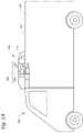
- FIG. 1Aillustrates a side view of a van with a transport climate control system, according to one embodiment.
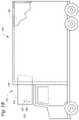
- FIG. 1Billustrates a side view of a truck with a transport climate control system, according to one embodiment.
- FIG. 1Cillustrates a perspective view of a climate controlled transport unit, with a transport climate control system, attached to a tractor, according to one embodiment.
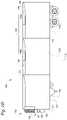
- FIG. 1Dillustrates a side view of a climate controlled transport unit with a multi-zone transport climate control system, according to one embodiment.
- FIG. 1Eillustrates a perspective view of a mass-transit vehicle including a transport climate control system, according to one embodiment.
- FIG. 2is a schematic diagram of a climate control circuit, according to one embodiment.
- FIG. 3is a schematic diagram of a climate control power system, according to one embodiment.
- the disclosure hereinrelates to an electrical architecture for a transport climate control system.
- a transport climate control systemis provided with a diesel engine as a prime mover driving a motor-generator-rectifier machine via a belt drive to provide a low voltage DC power to drive low voltage DC components such as low voltage DC condenser fan(s) and/or evaporator fan(s).
- low voltagerefers to Class A of the ISO 6469-3 in the automotive environment.
- low voltagerefers to a maximum working voltage of between 0V and 60V DC or between 0V and 30V AC.
- a low voltagecan be 12 VDC, 24 VDC, 48 VDC, or other suitable DC voltage.
- high voltagerefers to Class B of the ISO 6469-3 in the automotive environment.
- high voltagerefers to a maximum working voltage of between 60V and 1500V DC or between 30V and 1000V AC.
- a high voltagecan be 350 VDC, 400 VDC, 700 VDC, 800 VDC or other suitable DC voltage.
- FIG. 1Adepicts a climate-controlled van 100 that includes a climate controlled space 105 for carrying cargo and a transport climate control system 110 for providing climate control within the climate controlled space 105 .
- the transport climate control system 110includes a climate control unit (CCU) 115 that is mounted to a rooftop 120 of the van 100 .
- the transport climate control system 110can include, amongst other components, a climate control circuit (see FIG. 2 ) that connects, for example, a compressor, a condenser, an evaporator and an expansion device to provide climate control within the climate controlled space 105 .
- climate-controlled vanscan apply to any type of transport unit (e.g., a truck, a container (such as a container on a flat car, an intermodal container, a marine container, etc.), a box car, a semi-tractor, a bus, or other similar transport unit), etc.
- transport unite.g., a truck, a container (such as a container on a flat car, an intermodal container, a marine container, etc.), a box car, a semi-tractor, a bus, or other similar transport unit), etc.
- the transport climate control system 110also includes a programmable climate controller 125 and one or more sensors (not shown) that are configured to measure one or more parameters of the transport climate control system 110 (e.g., an ambient temperature outside of the van 100 , an ambient humidity outside of the van 100 , a compressor suction pressure, a compressor discharge pressure, a supply air temperature of air supplied by the CCU 115 into the climate controlled space 105 , a return air temperature of air returned from the climate controlled space 105 back to the CCU 115 , a humidity within the climate controlled space 105 , etc.) and communicate parameter data to the climate controller 125 .
- the climate controller 125is configured to control operation of the transport climate control system 110 including the components of the climate control circuit.
- the climate controller unit 115may comprise a single integrated control unit 126 or may comprise a distributed network of climate controller elements 126 , 127 . The number of distributed control elements in a given network can depend upon the particular application of the principles described herein.
- FIG. 1Bdepicts a climate-controlled straight truck 130 that includes a climate controlled space 131 for carrying cargo and a transport climate control system 132 .
- the transport climate control system 132includes a CCU 133 that is mounted to a front wall 134 of the climate controlled space 131 .
- the CCU 133can include, amongst other components, a climate control circuit (see FIG. 2 ) that connects, for example, a compressor, a condenser, an evaporator and an expansion device to provide climate control within the climate controlled space 131 .
- the transport climate control system 132also includes a programmable climate controller 135 and one or more sensors (not shown) that are configured to measure one or more parameters of the transport climate control system 132 (e.g., an ambient temperature outside of the truck 130 , an ambient humidity outside of the truck 130 , a compressor suction pressure, a compressor discharge pressure, a supply air temperature of air supplied by the CCU 133 into the climate controlled space 131 , a return air temperature of air returned from the climate controlled space 131 back to the CCU 133 , a humidity within the climate controlled space 131 , etc.) and communicate parameter data to the climate controller 135 .
- the climate controller 135is configured to control operation of the transport climate control system 132 including components of the climate control circuit.
- the climate controller 135may comprise a single integrated control unit 136 or may comprise a distributed network of climate controller elements 136 , 137 . The number of distributed control elements in a given network can depend upon the particular application of the principles described herein.
- FIG. 1Cillustrates one embodiment of a climate controlled transport unit 140 attached to a tractor 142 .
- the climate controlled transport unit 140includes a transport climate control system 145 for a transport unit 150 .
- the tractor 142is attached to and is configured to tow the transport unit 150 .
- the transport unit 150 shown in FIG. 1Cis a trailer.
- the transport climate control system 145includes a CCU 152 that provides environmental control (e.g. temperature, humidity, air quality, etc.) within a climate controlled space 154 of the transport unit 150 .
- the CCU 152is disposed on a front wall 157 of the transport unit 150 . In other embodiments, it will be appreciated that the CCU 152 can be disposed, for example, on a rooftop or another wall of the transport unit 150 .
- the CCU 152includes a climate control circuit (see FIG. 2 ) that connects, for example, a compressor, a condenser, an evaporator and an expansion device to provide conditioned air within the climate controlled space 154 .
- the transport climate control system 145also includes a programmable climate controller 156 and one or more sensors (not shown) that are configured to measure one or more parameters of the transport climate control system 145 (e.g., an ambient temperature outside of the transport unit 150 , an ambient humidity outside of the transport unit 150 , a compressor suction pressure, a compressor discharge pressure, a supply air temperature of air supplied by the CCU 152 into the climate controlled space 154 , a return air temperature of air returned from the climate controlled space 154 back to the CCU 152 , a humidity within the climate controlled space 154 , etc.) and communicate parameter data to the climate controller 156 .
- the climate controller 156is configured to control operation of the transport climate control system 145 including components of the climate control circuit.
- the climate controller 156may comprise a single integrated control unit 158 or may comprise a distributed network of climate controller elements 158 , 159 . The number of distributed control elements in a given network can depend upon the particular application of the principles described herein.
- FIG. 1Dillustrates another embodiment of a climate controlled transport unit 160 .
- the climate controlled transport unit 160includes a multi-zone transport climate control system (MTCS) 162 for a transport unit 164 that can be towed, for example, by a tractor (not shown).
- MTCSmulti-zone transport climate control system
- the MTCS 162includes a CCU 166 and a plurality of remote units 168 that provide environmental control (e.g. temperature, humidity, air quality, etc.) within a climate controlled space 170 of the transport unit 164 .
- the climate controlled space 170can be divided into a plurality of zones 172 .
- the term “zone”means a part of an area of the climate controlled space 170 separated by walls 174 .
- the CCU 166can operate as a host unit and provide climate control within a first zone 172 a of the climate controlled space 166 .
- the remote unit 168 acan provide climate control within a second zone 172 b of the climate controlled space 170 .
- the remote unit 168 bcan provide climate control within a third zone 172 c of the climate controlled space 170 . Accordingly, the MTCS 162 can be used to separately and independently control environmental condition(s) within each of the multiple zones 172 of the climate controlled space 162 .
- the CCU 166is disposed on a front wall 167 of the transport unit 160 . In other embodiments, it will be appreciated that the CCU 166 can be disposed, for example, on a rooftop or another wall of the transport unit 160 .
- the CCU 166includes a climate control circuit (see FIG. 2 ) that connects, for example, a compressor, a condenser, an evaporator and an expansion device to provide conditioned air within the climate controlled space 170 .
- the remote unit 168 ais disposed on a ceiling 179 within the second zone 172 b and the remote unit 168 b is disposed on the ceiling 179 within the third zone 172 c .
- Each of the remote units 168 a , 168 binclude an evaporator (not shown) that connects to the rest of the climate control circuit provided in the CCU 166 .
- the MTCS 162also includes a programmable climate controller 180 and one or more sensors (not shown) that are configured to measure one or more parameters of the MTCS 162 (e.g., an ambient temperature outside of the transport unit 164 , an ambient humidity outside of the transport unit 164 , a compressor suction pressure, a compressor discharge pressure, supply air temperatures of air supplied by the CCU 166 and the remote units 168 into each of the zones 172 , return air temperatures of air returned from each of the zones 172 back to the respective CCU 166 or remote unit 168 a or 168 b , a humidity within each of the zones 118 , etc.) and communicate parameter data to a climate controller 180 .
- a climate controller 180e.g., a climate controller 180 .
- the climate controller 180is configured to control operation of the MTCS 162 including components of the climate control circuit.
- the climate controller 180may comprise a single integrated control unit 181 or may comprise a distributed network of climate controller elements 181 , 182 .
- the number of distributed control elements in a given networkcan depend upon the particular application of the principles described herein.
- FIG. 1Eis a perspective view of a vehicle 185 including a transport climate control system 187 , according to one embodiment.
- the vehicle 185is a mass-transit bus that can carry passenger(s) (not shown) to one or more destinations. In other embodiments, the vehicle 185 can be a school bus, railway vehicle, subway car, or other commercial vehicle that carries passengers.
- the vehicle 185includes a climate controlled space (e.g., passenger compartment) 189 supported that can accommodate a plurality of passengers.
- the vehicle 185includes doors 190 that are positioned on a side of the vehicle 185 . In the embodiment shown in FIG.
- a first door 190is located adjacent to a forward end of the vehicle 185 , and a second door 190 is positioned towards a rearward end of the vehicle 185 .
- Each door 190is movable between an open position and a closed position to selectively allow access to the climate controlled space 189 .
- the transport climate control system 187includes a CCU 192 attached to a roof 194 of the vehicle 185 .
- the CCU 192includes a climate control circuit (see FIG. 2 ) that connects, for example, a compressor, a condenser, an evaporator and an expansion device to provide conditioned air within the climate controlled space 189 .
- the transport climate control system 187also includes a programmable climate controller 195 and one or more sensors (not shown) that are configured to measure one or more parameters of the transport climate control system 187 (e.g., an ambient temperature outside of the vehicle 185 , a space temperature within the climate controlled space 189 , an ambient humidity outside of the vehicle 185 , a space humidity within the climate controlled space 189 , etc.) and communicate parameter data to the climate controller 195 .
- the climate controller 195is configured to control operation of the transport climate control system 187 including components of the climate control circuit.
- the climate controller 195may comprise a single integrated control unit 196 or may comprise a distributed network of climate controller elements 196 , 197 .
- the number of distributed control elements in a given networkcan depend upon the particular application of the principles described herein.
- FIG. 2is a schematic diagram of a climate control circuit 200 , according to one embodiment.
- the climate control circuit 200can be used, for example, in the transport climate control systems 110 , 132 , 145 , 162 and 187 (shown in FIGS. 1A-1E ).
- the climate control circuit 200generally includes a compressor 220 , a condenser 240 , an expansion device 260 , and an evaporator 280 .
- the climate control circuit 200is an example and can be modified to include additional components.
- the climate control circuit 200can include other components such as, but not limited to, an economizer heat exchanger, one or more flow control devices, a receiver tank, a dryer, a suction-liquid heat exchanger, one or more condenser blowers/fans, one or more evaporator blowers/fans, one or more sensors, a controller, or the like.
- an economizer heat exchangersuch as, but not limited to, an economizer heat exchanger, one or more flow control devices, a receiver tank, a dryer, a suction-liquid heat exchanger, one or more condenser blowers/fans, one or more evaporator blowers/fans, one or more sensors, a controller, or the like.
- the climate control circuit 200can generally be applied in a variety of systems used to control an environmental condition (e.g., temperature, humidity, air quality, or the like) in a space (generally referred to as a conditioned space). Examples of such systems include, but are not limited to, HVAC systems, transport climate control systems, or the like. In one embodiment, an HVAC system can be a rooftop unit or a heat pump air-conditioning unit.
- the compressor 220 , condenser 240 , expansion device 260 , and evaporator 280are fluidly connected.
- the climate control circuit 200can be configured to be a cooling system (e.g., an air conditioning system) capable of operating in a cooling mode.
- the climate control circuit 200can be configured to be a heat pump system that can operate in both a cooling mode and a heating/defrost mode.
- the climate control circuit 200can operate according to generally known principles.
- the climate control circuit 200can be configured to heat or cool a liquid process fluid (e.g., a heat transfer fluid or medium (e.g., a liquid such as, but not limited to, water or the like)), in which case the climate control circuit 200 may be generally representative of a liquid chiller system.
- the climate control circuit 200can alternatively be configured to heat or cool a gaseous process fluid (e.g., a heat transfer medium or fluid (e.g., a gas such as, but not limited to, air or the like)), in which case the climate control circuit 200 may be generally representative of an air conditioner or heat pump.
- a liquid process fluide.g., a heat transfer fluid or medium (e.g., a liquid such as, but not limited to, water or the like)
- a gaseous process fluide.g., a heat transfer medium or fluid (e.g., a gas such as, but not limited to, air or the like)
- the compressor 220compresses a working fluid (e.g., a heat transfer fluid (e.g., refrigerant or the like)) from a relatively lower pressure gas to a relatively higher-pressure gas.
- a working fluide.g., a heat transfer fluid (e.g., refrigerant or the like)
- the relatively higher-pressure gasis also at a relatively higher temperature, which is discharged from the compressor 220 and flows through the condenser 240 .
- the working fluidflows through the condenser 200 and rejects heat to the process fluid (e.g., water, air, etc.), thereby cooling the working fluid.
- the cooled working fluidwhich is now in a liquid form, flows to the expansion device 260 .
- the expansion device 260reduces the pressure of the working fluid.
- the working fluidwhich is now in a mixed liquid and gaseous form flows to the evaporator 280 .
- the working fluidflows through the evaporator 280 and absorbs heat from the process fluid (e.g., a heat transfer medium (e.g., water, air, etc.)), heating the working fluid, and converting it to a gaseous form.
- the gaseous working fluidthen returns to the compressor 220 .
- the above-described processcontinues while the heat transfer circuit is operating, for example, in a cooling mode.
- FIG. 3is a schematic diagram of a climate control power system 300 , according to one embodiment.
- the climate control power system 300can be used to provide energy for powering the compressor 220 and at least one condenser fan associated with the condenser 240 and at least one evaporator fan associated with the evaporator 280 of the climate control circuit 200 of FIG. 2 .
- the climate control power system 300can also power any other components (e.g., vehicle tail lift charger, auxiliary lighting systems inside the climate controlled space, etc.) of a transport climate control system (e.g., the transport climate control systems 110 , 132 , 145 , 162 and 187 shown in FIGS. 1A-1E ).
- the climate control power system 300includes a compressor 307 (e.g., the compressor 220 shown in FIG. 2 ), a belt drive 306 , a prime mover 304 and a clutch 320 .
- the compressor 307can be mechanically driven by the belt drive 306 or by the prime mover 304 via a clutch 320 .
- the prime mover 304can be an internal combustion engine (e.g., a diesel engine, a compression-ignition engine, etc.). In one embodiment, the compressor 307 can be directly mounted to the prime mover 304 via the clutch 320 .
- the prime mover 304can be configured to, e.g., mechanically drive the compressor 307 via the clutch 320 when the clutch 320 is engaged (to the compressor 307 and the belt drive 306 ).
- the clutch 320does not engage the compressor 307 to the belt drive 306
- the compressor 307can be driven by a motor-generator-rectifier machine 305 via the belt drive 306 .
- the motor-generator-rectifier machine 305includes a motor 315 (e.g., an AC motor winding), a generator 308 (e.g., a low voltage AC generator winding to generate electrical power when a shaft of the motor-generator-rectifier machine 305 is rotating) connected to the motor 315 , and a rectifier 309 (e.g., an AC-DC rectifier) connected to the generator 308 .
- a motor 315e.g., an AC motor winding
- a generator 308e.g., a low voltage AC generator winding to generate electrical power when a shaft of the motor-generator-rectifier machine 305 is rotating
- a rectifier 309e.g., an AC-DC rectifier
- the motor-generator-rectifier machine 305can be powered and/or driven by the prime mover 304 via the belt drive 306 , to provide power.
- the compressor 307can be directly driven by the prime mover 304 via the clutch 320 .
- the motor-generator-rectifier machine 305can connect to an AC power source 314 .
- the clutch 320(and thus the prime mover 304 ) is disengaged from the compressor 307 and the belt drive 306 .
- the AC power source 314can be, for example, a shore/utility power source.
- the AC power source 314can be a three-phase AC power source.
- the AC power source 314can provide power to the motor 315 of the motor-generator-rectifier machine 305 to energize the motor 315 .
- the motor 315can be an electric motor.
- the motor 315is a standby motor, which serves as an alternate prime mover to provide power to the climate control power system 300 , for example, when the prime mover 304 is unavailable to provide power.
- the motor 315When the motor 315 is energized, the motor 315 can rotate a shaft (not shown) of the motor-generator-rectifier machine 305 . It will be appreciated that the motor 315 and the generator 308 are on the same shaft. The shaft of the motor-generator-rectifier machine 305 can propel the generator 308 so that the generator 308 can generate AC power.
- the generator 308is a low voltage generator.
- the AC power generated by the generator 308is distributed to the rectifier 309 .
- the rectifier 309is an active rectifier.
- the rectifier 309can convert the AC power generated by the generator 308 , to e.g., a low voltage DC power. In one embodiment, the voltage of the converted low voltage DC power is 48 volts.
- the motor 315When the motor 315 is energized, the motor 315 can also drive the compressor 307 via the belt drive 306 .
- the climate control power system 300includes at least one condenser fan 310 , at least one evaporator fan 311 , and a DC to DC converter 312 .
- the at least one condenser fan 310can be a variable speed fan.
- the at least one condenser fan 310can be a low voltage DC fan.
- the at least one evaporator fan 311can be a variable speed fan.
- the at least one evaporator fan 311can be a low voltage DC fan.
- the converted low voltage DC power from the rectifier 309is distributed to the at least one condenser fan 310 , the at least one evaporator fan 311 , and the DC to DC converter 312 .
- the DC to DC converter 312is a buck converter that lowers the converted low voltage DC power from the rectifier 309 , to a second low voltage DC power.
- the second low voltage DC poweris distributed to a control system 313 to power and/or charge the control system 313 .
- the control system 313can include a controller, a rechargeable energy storage system (e.g., a battery), a battery charger, solenoid(s), and/or valve(s), etc.
- the voltage of the second low voltage DC poweris 12 volts.
- the prime mover 304In operation, in a running mode of the climate control power system 300 , the prime mover 304 is engaged with the compressor 307 and the belt drive 306 , via the clutch 320 . In such mode, the prime mover 304 directly drives the compressor 307 , which is directly mounted to the prime mover 304 .
- the prime mover 304connects to and drives the motor-generator-rectifier machine 305 via the belt drive 306 , such that the generator 308 of the motor-generator-rectifier machine 305 can provide a low voltage AC power to the rectifier 309 of the motor-generator-rectifier machine 305 .
- the rectifier 309can convert the low voltage AC power to a low voltage DC power to drive the low voltage DC fans (the at least one condenser fan 310 and at least one evaporator fan 311 ) and to provide power to the DC to DC convertor 312 .
- the DC to DC convertor 312can convert the low voltage DC power from the rectifier 309 to a second low voltage DC voltage to power and/or charge the control system 313 (e.g., charging the battery of the control system 313 , providing DC power to the solenoid(s) and valve(s) of the control system 313 , etc.).
- the prime mover 304is disengaged with the compressor 307 and the belt drive 306 , via the clutch 320 .
- the AC power source 314can provide power to the climate control circuit 300 when connected to the motor 315 to energize the motor 315 .
- the motor 315When the motor 315 is energized, the motor 315 can rotate the shaft of the motor-generator-rectifier machine 315 , which can propel the generator 308 to provide a low voltage AC power to the rectifier 309 which in turn can convert the low voltage AC power to a low voltage DC power to drive the low voltage DC fans (the at least one condenser fan 310 and at least one evaporator fan 311 ) and to provide power to the DC to DC convertor 312 .
- the generator 308When the motor 315 is energized, the motor 315 can rotate the shaft of the motor-generator-rectifier machine 315 , which can propel the generator 308 to provide a low voltage AC power to the rectifier 309 which in turn can convert the low voltage AC power to a low voltage DC power to drive the low voltage DC fans (the at least one condenser fan 310 and at least one evaporator fan 311 ) and to provide power to the DC to DC convertor 312 .
- the low voltage DC fansthe
- the DC to DC convertor 312can convert the low voltage DC power from the rectifier 309 to a second low voltage DC power to power and/or charge the control system 313 (e.g., charging the battery of the control system 313 , providing DC power to the solenoid(s) and valve(s) of the control system 313 , etc.).
- the motor 315When the motor 315 is energized, the motor 315 can also drive the compressor 307 via the belt drive 306 .
- Embodiments disclosed hereinallow each of the at least one condenser fan 310 and the at least one evaporator fan 311 to be individually and independently powered and controlled (e.g., by the controller). As such, the speed of the at least one condenser fan 310 and/or the speed of the at least one evaporator fan 311 can be controlled independent of the speed of the prime mover 304 and/or the speed of the generator 308 .
- the at least one condenser fan 310 and/or the at least one evaporator fan 311can be fully variable speed fans. In such embodiment, the at least one condenser fan 310 and/or the at least one evaporator fan 311 can have more than two speeds. It will be appreciated that a two-speed fan refers to a fan with a high speed and a low speed corresponding to a two-speed engine/generator that drives the fan.
- the fans ( 310 and/or 311 )can be configured to run continuously and/or in a cycle-sentry mode. The speed of the fans ( 310 and/or 311 ) can be controlled (e.g., by the controller) to optimize at each point around fuel economy.
- the speed of the fans ( 310 and/or 311 )can be controlled based on a curve fit which is based on e.g., prime mover (e.g., engine) speed, ambient temperature, and/or box temperature (e.g., temperature of the climate controlled space), during operations such as pulldown.
- the curve fit of the fan speed(a curve used by the controller to determine the speed of the fan) can be based on the speed of the compressor, ambient temperature, and/or box temperature.
- the speed of the fans ( 310 and/or 311 )can be controlled based on the load of the transport climate control system.
- the curve fit of the fan speed(a curve used by the controller to determine the speed of the fan) can be used when, e.g., an AC power source (such as utility/shore power) is used and the prime mover is disengaged.
- an automotive belt-driven-starter-generatorBSG
- BSGautomotive belt-driven-starter-generator
- the motor-generator-rectifier machine 305 of FIG. 3can be belt driven, or be directly coupled to the motor 315 to provide a low voltage DC power to the low voltage DC fans (e.g., the at least one condenser fan 310 and at least one evaporator fan 311 ) and to the DC to DC converter 312 .
- the motor 315can be directly coupled to a high voltage generator (to replace the low voltage generator 308 ), where the generator can provide high voltage AC power (e.g., 400 VAC, 50 Hz).
- the high voltage generatorcan be a belt driven device providing high voltage AC.
- the high voltage AC generated by either of the two high voltage generator configurationscan then be input to an AC to DC converter, that can provide the required DC power levels for the at least one condenser fan 310 , the at least one evaporator fan 311 , and/or the control system 313 .
- ACe.g., high voltage AC
- the condenser and/or evaporator fanscan be powered by a high voltage generator and/or by the prime mover 304 .
- a transport climate control systemcomprising:
- At least one condenser fanAt least one condenser fan
- motor-generator-rectifier machineconnects to the at least one condenser fan, the at least one evaporator fan, and the DC to DC converter
- motor-generator-rectifier machineincludes:
- the motor-generator-rectifier machineis configured to provide a first low voltage DC power to the at least one condenser fan, the at least one evaporator fan, and the DC to DC converter, and
- the DC to DC converteris configured to convert the first low voltage DC power to a second low voltage DC power that is different from the first low voltage DC power.
- Aspect 2The transport climate control system according to aspect 1, wherein the compressor is configured to be directly driven by a prime mover via a clutch.
- Aspect 3The transport climate control system according to aspect 1 or aspect 2, wherein the motor-generator-rectifier machine is configured to be driven by a prime mover via the belt drive.
- Aspect 4The transport climate control system according to any one of aspects 1-3, wherein the prime mover is a diesel engine.
- Aspect 5The transport climate control system according to any one of aspects 1-4, wherein the compressor is configured to be driven by the motor via the belt drive.
- Aspect 6The transport climate control system according to aspect 1, wherein the motor is configured to be driven by an AC power source.
- Aspect 7The transport climate control system according to aspect 6, wherein the motor is configured to rotate a shaft of the motor-generator-rectifier machine, and the shaft is configured to propel the low voltage generator to provide power.
- Aspect 8The transport climate control system according to any one of aspects 1-7, wherein the DC to DC converter is a buck converter that lowers the first low voltage DC power to the second low voltage DC power.
- Aspect 9The transport climate control system according to any one of aspects 1-8, wherein the at least one condenser fan and/or the at least one evaporator fan are variable speed fans.
- Aspect 10The transport climate control system according to any one of aspects 1-9, wherein a speed of the at least one condenser fan and/or a speed of the at least one evaporator fan are controlled independent of a speed of a prime mover and/or a speed of the low voltage generator.
- Aspect 11The transport climate control system according to any one of aspects 1-10, wherein the first low voltage DC power is 48 volts and the second low voltage DC power is 12 volts.
- Aspect 12A method for distributing power for a transport climate control system, the method comprising:
- the motor-generator-rectifier machineincluding a motor, a low voltage generator, and a rectifier
- the motor-generator-rectifier machinegenerating a first low voltage DC power to drive at least one condenser fan, at least one evaporator fan, and a DC to DC converter,
- the DC to DC converterconverting the first low voltage DC power to a second low voltage DC power that is different from the first low voltage DC power.
- Aspect 13The method according to aspect 12, further comprising:
- the prime moverdriving the motor-generator-rectifier machine via a belt drive.
- Aspect 14The method according to aspect 12, further comprising:
- the shaftpropelling the low voltage generator to provide power.
- Aspect 15The method of any one of aspects 12-14, further comprising:
Landscapes
- Engineering & Computer Science (AREA)
- Mechanical Engineering (AREA)
- Thermal Sciences (AREA)
- Physics & Mathematics (AREA)
- Power Engineering (AREA)
- Life Sciences & Earth Sciences (AREA)
- Sustainable Development (AREA)
- Chemical & Material Sciences (AREA)
- Combustion & Propulsion (AREA)
- General Engineering & Computer Science (AREA)
- Transportation (AREA)
- Devices That Are Associated With Refrigeration Equipment (AREA)
- Electric Propulsion And Braking For Vehicles (AREA)
- Power Conversion In General (AREA)
- Handcart (AREA)
Abstract
Description
- a motor;
- a low voltage generator connected to the motor; and
- a rectifier connected to the low voltage generator,
Aspect 11. The transport climate control system according to any one of aspects 1-10, wherein the first low voltage DC power is 48 volts and the second low voltage DC power is 12 volts.
Aspect 12. A method for distributing power for a transport climate control system, the method comprising:
Claims (19)
Priority Applications (5)
| Application Number | Priority Date | Filing Date | Title |
|---|---|---|---|
| US16/730,126US11489431B2 (en) | 2019-12-30 | 2019-12-30 | Transport climate control system power architecture |
| ES20210695TES2967184T3 (en) | 2019-12-30 | 2020-11-30 | Power architecture for transportation climate control system |
| EP20210695.1AEP3845401B1 (en) | 2019-12-30 | 2020-11-30 | Transport climate control system power architecture |
| CN202011611449.3ACN113119691B (en) | 2019-12-30 | 2020-12-30 | Transportation Climate Control System Power Architecture |
| US18/049,060US11843303B2 (en) | 2019-12-30 | 2022-10-24 | Transport climate control system power architecture |
Applications Claiming Priority (1)
| Application Number | Priority Date | Filing Date | Title |
|---|---|---|---|
| US16/730,126US11489431B2 (en) | 2019-12-30 | 2019-12-30 | Transport climate control system power architecture |
Related Child Applications (1)
| Application Number | Title | Priority Date | Filing Date |
|---|---|---|---|
| US18/049,060ContinuationUS11843303B2 (en) | 2019-12-30 | 2022-10-24 | Transport climate control system power architecture |
Publications (2)
| Publication Number | Publication Date |
|---|---|
| US20210203217A1 US20210203217A1 (en) | 2021-07-01 |
| US11489431B2true US11489431B2 (en) | 2022-11-01 |
Family
ID=73646216
Family Applications (2)
| Application Number | Title | Priority Date | Filing Date |
|---|---|---|---|
| US16/730,126Active2041-01-02US11489431B2 (en) | 2019-12-30 | 2019-12-30 | Transport climate control system power architecture |
| US18/049,060ActiveUS11843303B2 (en) | 2019-12-30 | 2022-10-24 | Transport climate control system power architecture |
Family Applications After (1)
| Application Number | Title | Priority Date | Filing Date |
|---|---|---|---|
| US18/049,060ActiveUS11843303B2 (en) | 2019-12-30 | 2022-10-24 | Transport climate control system power architecture |
Country Status (4)
| Country | Link |
|---|---|
| US (2) | US11489431B2 (en) |
| EP (1) | EP3845401B1 (en) |
| CN (1) | CN113119691B (en) |
| ES (1) | ES2967184T3 (en) |
Families Citing this family (1)
| Publication number | Priority date | Publication date | Assignee | Title |
|---|---|---|---|---|
| US20230271476A1 (en)* | 2022-02-28 | 2023-08-31 | Carrier Corporation | Transport refrigeration system having direct current power sources |
Citations (265)
| Publication number | Priority date | Publication date | Assignee | Title |
|---|---|---|---|---|
| US3875483A (en) | 1972-01-03 | 1975-04-01 | Tecumseh Products Co | Power supply for refrigeration units |
| EP0282051A2 (en) | 1987-03-12 | 1988-09-14 | Alex Müller | Tractor or trailer for transporting loads with an installation for cooling the load compartment by air circulation |
| DE3817365A1 (en) | 1988-05-20 | 1989-11-30 | Mueller Alex | Lorry or trailer with a loading area or refrigeration chamber cooled by a refrigeration unit at the front end by means of air circulation |
| US5104037A (en) | 1990-10-26 | 1992-04-14 | Aeg Westinghouse Transportation Systems, Inc. | Microprocessor controlled climate control device for a plurality of mass transit vehicles |
| EP0536552A1 (en) | 1991-09-12 | 1993-04-14 | Jacobs Japan, Inc. | A non-handle type tool chuck |
| US5231849A (en) | 1992-09-15 | 1993-08-03 | Rosenblatt Joel H | Dual-temperature vehicular absorption refrigeration system |
| DE29715576U1 (en) | 1997-09-01 | 1997-12-04 | Zeeuw, Hans de, 47228 Duisburg | Air distributor for cold rooms |
| JP2000158930A (en) | 1998-11-28 | 2000-06-13 | Hino Auto Body Ltd | Method and device for supplying air conditioning air for vehicle |
| US6280320B1 (en) | 1999-07-13 | 2001-08-28 | Rite-Hite Holding Corporation | Frame to support a deflated fabric air duct |
| CN2456117Y (en) | 2000-12-28 | 2001-10-24 | 上海纽福克斯汽车配件有限公司 | Universal electric refrigerator |
| US20020113576A1 (en) | 2001-02-21 | 2002-08-22 | Mitsuyo Oomura | Charging control system for air conditioner and battery |
| US6487869B1 (en) | 2001-11-06 | 2002-12-03 | Themo King Corporation | Compressor capacity control system |
| DE10138750A1 (en) | 2001-07-30 | 2003-02-27 | Caa Ag | Vehicle computer system for determining and displaying load power consumption has energy detection device that provides consumption data to evaluation device driving display |
| US20030043607A1 (en) | 2001-08-31 | 2003-03-06 | Patrizio Vinciarelli | Passive control of harmonic current drawn from an AC input by rectification circuitry |
| WO2003038988A1 (en) | 2001-10-02 | 2003-05-08 | Arthur Naiman | Speed and direction control for capacitor motors |
| US6560980B2 (en) | 2000-04-10 | 2003-05-13 | Thermo King Corporation | Method and apparatus for controlling evaporator and condenser fans in a refrigeration system |
| US20030106332A1 (en) | 2000-06-28 | 2003-06-12 | Hiroshi Okamoto | Refrigerating apparatus for use in vehicles, using an engine as power source |
| US6600237B1 (en) | 1999-11-18 | 2003-07-29 | Vb Autobatterie Gmbh | Method for controlling a plurality of electrical loads operated at the same time by a current source |
| US6631080B2 (en) | 2001-06-06 | 2003-10-07 | Hybrid Power Generation Systems Llc | Systems and methods for boosting DC link voltage in turbine generators |
| US20030200017A1 (en) | 2002-04-23 | 2003-10-23 | Capps Rick W. | Method and handling apparatus for a vehicular electrical system |
| DE10200637C1 (en) | 2002-01-10 | 2003-10-30 | Guenter Grams | Control method for automobile climate-control device, provides stepped switching in of individual climate-control elements for limiting switching in current |
| US20030201097A1 (en) | 2002-04-29 | 2003-10-30 | Bergstrom, Inc. | Vehicle air conditioning and heating system providing engine on and engine off operation |
| US6652330B1 (en) | 2002-08-06 | 2003-11-25 | Brunswick Corporation | Storage battery monitoring system with automatic electrical load shedding |
| US6753692B2 (en) | 2000-03-29 | 2004-06-22 | Canon Kabushiki Kaisha | Method and apparatus for testing solar panel, manufacturing method for manufacturing the solar panel, method and apparatus for inspecting solar panel generating system, insulation resistance measuring apparatus, and withstand voltage tester |
| US20050057210A1 (en) | 2003-09-09 | 2005-03-17 | Mitsuo Ueda | Converter circuit and motor driving apparatus |
| US20050065684A1 (en) | 2003-09-10 | 2005-03-24 | Larson Gerald L. | Modularized power take-off systems for vehicles |
| US6925826B2 (en) | 2003-05-05 | 2005-08-09 | Carrier Corporation | Modular bus air conditioning system |
| US7011902B2 (en) | 2003-03-12 | 2006-03-14 | Ballard Power Systems Inc. | Black start method and apparatus for a fuel cell power plant, and fuel cell power plant with black start capability |
| US20060061307A1 (en)* | 2004-08-09 | 2006-03-23 | Donnelly Frank W | Locomotive power train architecture |
| US7120539B2 (en) | 2001-12-21 | 2006-10-10 | Garmin Ltd. | Navigation system, method and device with detour algorithm |
| US7122923B2 (en) | 2003-07-10 | 2006-10-17 | Magnetic Applications Inc. | Compact high power alternator |
| US7151326B2 (en) | 2003-09-23 | 2006-12-19 | Idle Free Systems, L.L.C. | System and method for safely and efficiently capturing power currently produced by already available power supplies to power electrical devices in a truck while its engine is turned off |
| US20060284601A1 (en) | 2004-07-02 | 2006-12-21 | Lembit Salasoo | High temperature battery system for hybrid locomotive and offhighway vehicles |
| CN1885660A (en) | 2006-06-16 | 2006-12-27 | 太原钢铁(集团)有限公司 | High power motor over-voltage protection device |
| US7176658B2 (en) | 2003-06-02 | 2007-02-13 | Magnetic Applications Inc. | Controller for permanent magnet alternator |
| US20070052241A1 (en) | 2005-08-31 | 2007-03-08 | Pacy David H | Auxiliary power device for refrigerated trucks |
| US7206692B2 (en) | 2001-12-11 | 2007-04-17 | Garmin Ltd. | System and method for estimating impedance time through a road network |
| CN2912069Y (en) | 2006-06-16 | 2007-06-13 | 太原钢铁(集团)有限公司 | Over-voltage protector of large power dynamo |
| US20070130950A1 (en)* | 2005-12-12 | 2007-06-14 | Alexander Serkh | Auxiliary power system for a motor vehicle |
| US20070192116A1 (en) | 2006-02-10 | 2007-08-16 | Garmin Ltd., A Cayman Islands Corporation | Position-sensitive events |
| JP2007320352A (en) | 2006-05-30 | 2007-12-13 | Toyota Motor Corp | In-vehicle device control system |
| US7327123B2 (en) | 2005-02-02 | 2008-02-05 | Magnetic Applications, Inc. | Controller for AC generator |
| EP1935712A1 (en) | 2006-12-22 | 2008-06-25 | Nederlandse Organisatie voor Toegepast-Natuuurwetenschappelijk Onderzoek TNO | Vehicle system and method |
| US20080177678A1 (en) | 2007-01-24 | 2008-07-24 | Paul Di Martini | Method of communicating between a utility and its customer locations |
| WO2008094148A1 (en) | 2007-01-31 | 2008-08-07 | Carrier Corporation | Integrated multiple power conversion system for transport refrigeration units |
| US7424343B2 (en) | 2004-08-11 | 2008-09-09 | Lawrence Kates | Method and apparatus for load reduction in an electric power system |
| US7449798B2 (en) | 2002-08-01 | 2008-11-11 | I-Hits Laboratory | Co-generated power supply system |
| US20080281473A1 (en) | 2007-05-08 | 2008-11-13 | Pitt Ronald L | Electric energy bill reduction in dynamic pricing environments |
| WO2008153518A1 (en) | 2007-06-07 | 2008-12-18 | Carrier Corporation | Transport refrigeration unit auxiliary power |
| US7532960B2 (en) | 2001-03-27 | 2009-05-12 | General Electric Company | Hybrid energy off highway vehicle electric power management system and method |
| US20090121798A1 (en) | 2007-08-10 | 2009-05-14 | Melvin Leroy Levinson | High power microwave waste management |
| US20090122901A1 (en) | 2007-11-09 | 2009-05-14 | Lg Electronics Inc. | Method for configurating basic signal allocation unit and method for transmitting signals using the same |
| US20090126901A1 (en) | 2007-11-20 | 2009-05-21 | Thermo King Corporation | External noise reduction of hvac system for a vehicle |
| US20090178424A1 (en) | 2007-12-21 | 2009-07-16 | Lg Electronics Inc. | Air conditioner |
| US20090195349A1 (en) | 2008-02-01 | 2009-08-06 | Energyhub | System and method for home energy monitor and control |
| US20090228155A1 (en) | 2007-11-23 | 2009-09-10 | Slifkin Timothy P | Display and management of events in transport refrigeration units |
| JP2009243780A (en) | 2008-03-31 | 2009-10-22 | Panasonic Corp | Air duct for painting work and air supply device for painting work |
| US20090314019A1 (en) | 2007-01-26 | 2009-12-24 | Yuji Fujimoto | Refrigeration unit for refrigerated vehicle |
| WO2009155941A1 (en) | 2008-06-24 | 2009-12-30 | Carrier Corporation | Method of controlling an air cooled heat exchanger |
| US20090320515A1 (en) | 2006-08-29 | 2009-12-31 | BSH Bosch und Siemens Hausgeräte GmbH | Refrigerating device comprising a pressure compensation opening |
| CN101713577A (en) | 2009-09-21 | 2010-05-26 | 浙江大学 | Wind-driven thermoacoustic vehicle air conditioning |
| US7728546B2 (en) | 2006-03-20 | 2010-06-01 | Denso Corporation | Multiple power supply apparatus with improved installability |
| US7730981B2 (en) | 2005-10-19 | 2010-06-08 | The Raymond Corporation | Lift truck with hybrid power source |
| WO2010065476A2 (en) | 2008-12-01 | 2010-06-10 | Odyne Systems, Llc | Hybrid drive for medium and heavy duty trucks |
| US7745953B2 (en) | 2005-05-02 | 2010-06-29 | Magneti Marelli Powertrain S.P.A. | Energy storage system for powering vehicle electric user devices |
| US20100230224A1 (en) | 2009-03-13 | 2010-09-16 | Donald Hindman | Cargo carrying vehicle with safety system for shore power connection |
| US7806796B2 (en) | 2006-03-14 | 2010-10-05 | Raphael Zhu | Power set for vehicles |
| US7830117B2 (en) | 2005-01-10 | 2010-11-09 | Odyne Systems, Llc | Vehicle charging, monitoring and control systems for electric and hybrid electric vehicles |
| US20100312425A1 (en) | 2009-06-05 | 2010-12-09 | Denso Corporation | Apparatus for managing energy supplied to functional device units realizing a specific function |
| US20100320018A1 (en) | 2009-06-18 | 2010-12-23 | Ford Global Technologies, Llc | Method And System To Prevent Vehicle Driveaway During Battery Charging |
| US20110000244A1 (en) | 2007-07-06 | 2011-01-06 | Carrier Corporation | Transport Refrigeration Series Hybrid Power Supply |
| US7898111B1 (en) | 2008-06-10 | 2011-03-01 | Network Engines, Inc. | Power supply methods and systems |
| US20110118916A1 (en) | 2009-11-17 | 2011-05-19 | Eric Gullichsen | Discrete Voltage Level Controller |
| US20110114398A1 (en) | 2009-11-17 | 2011-05-19 | Bianco James S | Battery Power System for Plug In Hybrid Tractor Trailers |
| WO2011066468A1 (en) | 2009-11-24 | 2011-06-03 | Telogis, Inc. | Vehicle route selection based on energy usage |
| US20110162395A1 (en) | 2008-09-17 | 2011-07-07 | Bruno Chakiachvili | Electrically powered transport refrigeration units |
| US20110208378A1 (en) | 2010-02-24 | 2011-08-25 | Gm Global Technology Operations, Inc. | Method for operating a hybrid vehicle |
| US20110224841A1 (en) | 2011-01-06 | 2011-09-15 | Ford Global Technologies, Llc | Methods and systems for monitoring a vehicle's energy source |
| US8020651B2 (en) | 2004-11-16 | 2011-09-20 | Volkswagen Aktiengesellschaft | Hybrid motor vehicle and method for controlling operation of a hybrid motor vehicle |
| US8030880B2 (en) | 2006-11-15 | 2011-10-04 | Glacier Bay, Inc. | Power generation and battery management systems |
| US20110241420A1 (en) | 2010-03-31 | 2011-10-06 | Zf Friedrichshafen Ag | Power supply device and unit |
| CN202038315U (en) | 2011-03-31 | 2011-11-16 | 青岛理工大学 | An externally connected variable cross-section uniform air supply system for high-speed trains |
| US20110290893A1 (en) | 2010-05-26 | 2011-12-01 | John Douglas Steinberg | System and method for using a mobile electronic device to optimize an energy management system |
| US20120000212A1 (en) | 2010-06-30 | 2012-01-05 | Thermo King Corporation | Transport refrigeration system with predictive refrigeration |
| US8134339B2 (en) | 2007-02-28 | 2012-03-13 | Stmicroelectronics, Inc. | Integrated circuit and method for preserving vehicle's battery charge and protecting trailer load |
| US8170886B2 (en) | 2008-03-28 | 2012-05-01 | The Nielsen Company (U.S.), Llc | Systems, methods, and apparatus to generate an energy consumption index |
| US20120116931A1 (en) | 2010-11-08 | 2012-05-10 | System Planning Corporation | Method for establishing an impromtu geofenced area to organize and analyze shipments |
| US20120153722A1 (en) | 2010-12-16 | 2012-06-21 | Ashot Nazarian | Method and apparatus for integrated electric power generation, storage and supply distributed and networked at the same time |
| US8214141B2 (en) | 2005-08-10 | 2012-07-03 | Rm Acquisition, Llc | Route evaluation system |
| US20120198866A1 (en) | 2009-10-23 | 2012-08-09 | Carrier Corporation | Spatial control of conditioned gas delivery for transport refrigeration system to include cargo spatial temperature distribution, and methods for same |
| KR20120092834A (en) | 2011-02-14 | 2012-08-22 | (주)정은테크 | Device for increasing ride comfort of train |
| WO2012138497A1 (en) | 2011-04-04 | 2012-10-11 | Carrier Corporation | Semi-electric mobile refrigerated system |
| WO2012138500A1 (en) | 2011-04-04 | 2012-10-11 | Carrier Corporation | Transport refrigeration system and method for operating |
| US8295950B1 (en)* | 2008-07-02 | 2012-10-23 | Jerry Lee Wordsworth | Intelligent power management system |
| US20120310416A1 (en) | 2011-06-03 | 2012-12-06 | Energyhub | Realization of energy savings potential through feedback |
| US20120310376A1 (en) | 2011-06-02 | 2012-12-06 | Microsoft Corporation | Occupancy prediction using historical occupancy patterns |
| DE102011050719A1 (en) | 2011-05-30 | 2012-12-06 | Lti Drives Gmbh | Emergency operative driving circuit for three-phase motor in pitch drives for e.g. wind power plant, has inverter unit supplied by intermediate circuit and another inverter unit supplied by storage device, so that motor is energized |
| US20130000342A1 (en) | 2010-01-29 | 2013-01-03 | Carrier Corporation | Solar power assisted transport refrigeration systems, transport refrigeration units and methods for same |
| US8381540B2 (en) | 2006-11-15 | 2013-02-26 | Crosspoint Solutions, Llc | Installable HVAC systems for vehicles |
| US20130073094A1 (en) | 2010-03-30 | 2013-03-21 | Telepure Limited | Building occupancy dependent control system |
| US20130088900A1 (en) | 2011-10-10 | 2013-04-11 | Jong-Ho Park | Energy storage system and controlling method of the same |
| US8441228B2 (en) | 2009-07-31 | 2013-05-14 | Thermo King Corporation | Bi-directional battery voltage converter |
| US20130158828A1 (en) | 2011-08-12 | 2013-06-20 | Mcalister Technologies, Llc | Reducing and/or harvesting drag energy from transport vehicles, including for chemical reactors, and associated systems and methods |
| WO2013096084A1 (en) | 2011-12-19 | 2013-06-27 | Carrier Corporation | Transport refrigeration system with regenerative elements |
| US8476872B2 (en) | 2009-08-12 | 2013-07-02 | Thermo King Corporation | Systems and methods of reducing a load on an engine |
| US8487458B2 (en) | 2008-01-17 | 2013-07-16 | Carrier Corporation | Two speed control for mobile refrigeration generators |
| US20130231808A1 (en) | 2012-01-30 | 2013-09-05 | Jeffrey C. Flath | Method and apparatus for vehicular energy management |
| US8602141B2 (en) | 2010-04-05 | 2013-12-10 | Daimler Trucks North America Llc | Vehicle power system with fuel cell auxiliary power unit (APU) |
| WO2014002244A1 (en) | 2012-06-29 | 2014-01-03 | 本田技研工業株式会社 | Vehicle equipped with electrical storage device and air conditioner |
| US8626419B2 (en) | 2012-04-27 | 2014-01-07 | Fleetmatics Irl Limited | System and method for automated identification of frequent stop locations for vehicle fleets |
| US20140018969A1 (en) | 2012-07-14 | 2014-01-16 | Joseph W. Forbes, Jr. | Method and Apparatus for Actively Managing Electric Power Supply for an Electric Power Grid |
| EP2689944A2 (en) | 2012-07-24 | 2014-01-29 | Mitsubishi Heavy Industries, Ltd. | Refrigeration system for transportation |
| US8643216B2 (en) | 2009-07-31 | 2014-02-04 | Thermo King Corporation | Electrical storage element control system for a vehicle |
| US8643217B2 (en) | 2007-12-26 | 2014-02-04 | Carrier Corporation | Apparatus and method for boosting output of a generator set |
| US20140060097A1 (en) | 2012-08-31 | 2014-03-06 | Philip PERREAULT | Refrigerated truck battery back-up system and related methods |
| US8670225B2 (en) | 2008-09-22 | 2014-03-11 | Carrier Corporation | Data logging device for supply chain management |
| EP2717016A1 (en) | 2012-10-05 | 2014-04-09 | Hitachi, Ltd. | Method and system for providing route assistance for electric vehicles |
| WO2014058610A1 (en) | 2012-10-08 | 2014-04-17 | Thermo King Corporation | Systems and methods for powering a transport refrigeration system |
| US8723344B1 (en) | 2010-06-24 | 2014-05-13 | James Dierickx | Energy harvesting system |
| US20140137590A1 (en) | 2011-07-07 | 2014-05-22 | Carrier Corporation | Integrated Transport Refrigeration Unit |
| US8742620B1 (en) | 2012-07-10 | 2014-06-03 | Geneva Holdings, LLC | Electrical cogeneration system and method |
| WO2014085672A1 (en) | 2012-11-28 | 2014-06-05 | Thermo King Corporation | Methods and systems to control an engine of a transport refrigeration unit |
| US8760115B2 (en) | 2009-08-20 | 2014-06-24 | GM Global Technology Operations LLC | Method for charging a plug-in electric vehicle |
| US8767379B2 (en) | 2013-02-11 | 2014-07-01 | Connecticut Electric, Inc. | Recreational vehicle user interface system and method |
| US8764469B2 (en) | 2012-09-28 | 2014-07-01 | Atlantic Great Dane, Inc. | Power supply system including panel with safety release |
| WO2014106060A1 (en) | 2012-12-27 | 2014-07-03 | Thermo King Corporation | Geographic specific controlling of a transport refrigeration system |
| WO2014106068A1 (en) | 2012-12-27 | 2014-07-03 | Thermo King Corporation | Systems and methods for engine power control for transport refrigeration system |
| US20140230470A1 (en) | 2013-02-15 | 2014-08-21 | City of Tallahassee | Vehicle Idle Time Reduction System and Method |
| US8818588B2 (en) | 2007-07-12 | 2014-08-26 | Odyne Systems, Llc | Parallel hybrid drive system utilizing power take off connection as transfer for a secondary energy source |
| US20140265560A1 (en) | 2013-03-15 | 2014-09-18 | Levant Power Corporation | System and method for using voltage bus levels to signal system conditions |
| US8862356B2 (en) | 2010-03-02 | 2014-10-14 | International Truck Intellectual Property Company, Llc | Regenerative brake system reset feature and adaptive calibration for hybrid and electric vehicles |
| US8912683B2 (en) | 2008-09-22 | 2014-12-16 | Open Energi Limited | Smart responsive electrical load |
| US8924057B2 (en) | 2010-03-19 | 2014-12-30 | GM Global Technology Operations LLC | Method for starting a hybrid vehicle |
| US20150019132A1 (en) | 2013-07-10 | 2015-01-15 | Ford Global Technologies, Llc | System and method for vehicle routing using stochastic optimization |
| US8978798B2 (en) | 2007-10-12 | 2015-03-17 | Odyne Systems, Llc | Hybrid vehicle drive system and method and idle reduction system and method |
| US20150081212A1 (en) | 2013-09-16 | 2015-03-19 | Fleetmatics Irl Limited | System and method for automated correction of geofences |
| CN104539184A (en) | 2014-12-12 | 2015-04-22 | 贵州永红航空机械有限责任公司 | Efficient transport refrigeration machine |
| US20150121923A1 (en) | 2012-05-01 | 2015-05-07 | Carrier Corporation | Transport refrigeration system having electric fans |
| US9030336B2 (en) | 2006-08-02 | 2015-05-12 | Omnitracs, Llc | Method and apparatus for obtaining weather information from road-going vehicles |
| US20150168032A1 (en) | 2011-12-19 | 2015-06-18 | Carrier Corporation | Power Supply System For Transport Refrigeration System |
| US9061680B2 (en) | 2007-07-12 | 2015-06-23 | Odyne Systems, Llc | Hybrid vehicle drive system and method for fuel reduction during idle |
| CN104734178A (en) | 2013-12-24 | 2015-06-24 | 珠海格力电器股份有限公司 | Solar air conditioning system and control method thereof |
| US20150188360A1 (en) | 2014-01-02 | 2015-07-02 | Robert W. Doane | Solar charging of multiple battery banks |
| WO2015100398A1 (en) | 2013-12-26 | 2015-07-02 | Thermo King Corporation | Method and system for dynamic power allocation in a transport refrigeration system |
| US9093788B2 (en) | 2012-09-28 | 2015-07-28 | Atlantic Great Dane, Inc. | Power supply system including panel with safety release |
| US9147335B2 (en) | 2011-12-22 | 2015-09-29 | Omnitracs, Llc | System and method for generating real-time alert notifications in an asset tracking system |
| US20150306937A1 (en) | 2013-01-17 | 2015-10-29 | Mitsubishi Electric Corporation | Vehicle air conditioning control device |
| US20150316301A1 (en) | 2014-05-02 | 2015-11-05 | Thermo King Corporation | Method and system for charging a transport refrigeration system |
| EP2942216A1 (en) | 2014-05-07 | 2015-11-11 | MAN Truck & Bus AG | Operating method for at least one air conditioning system of a vehicle |
| US20150345958A1 (en) | 2014-05-27 | 2015-12-03 | Atieva, Inc. | Method of Controlling an Auxiliary Vehicle System |
| US20150355288A1 (en) | 2013-02-19 | 2015-12-10 | Furukawa Electric Co., Ltd. | Secondary battery degradation determination method and secondary battery degradation determination device |
| US20150360568A1 (en)* | 2014-06-12 | 2015-12-17 | Hollywood Trucks, LLC | Solar-thermal powered recreational vehicle |
| US20160011001A1 (en) | 2014-07-08 | 2016-01-14 | Omnitracs, Llc | Integration of hours of service and navigation |
| US20160035152A1 (en) | 2013-12-31 | 2016-02-04 | Agnik, Llc | Vehicle data mining based on vehicle onboard analysis and cloud-based distributed data stream mining algorithm |
| WO2016038838A1 (en) | 2014-09-09 | 2016-03-17 | 株式会社デンソー | Refrigerating device and container refrigerating system |
| US20160089994A1 (en) | 2014-09-29 | 2016-03-31 | Daimler Ag | Battery management system for a motor vehicle |
| US9313616B2 (en) | 2013-09-16 | 2016-04-12 | Fleetmatics Development Limited | System and method for automated identification of location types for geofences |
| US20160144764A1 (en) | 2013-06-18 | 2016-05-26 | Thermo King Corporation | Control method for a hybrid refrigeration system |
| CN105711376A (en) | 2008-09-17 | 2016-06-29 | 开利公司 | Electric transport refrigeration unit |
| US20160252289A1 (en) | 2013-10-17 | 2016-09-01 | Carrier Corporation | Motor and drive arrangement for refrigeration system |
| US9436853B1 (en) | 2011-03-01 | 2016-09-06 | Globaltrak, Llc | Methods and apparatus for combining temperature data from separate segments of handling |
| US9440507B2 (en) | 2013-03-15 | 2016-09-13 | Levant Power Corporation | Context aware active suspension control system |
| WO2016145107A2 (en) | 2015-03-09 | 2016-09-15 | Bergstrom, Inc. | System and method for remotely managing climate control systems of a fleet of vehicles |
| US20160285416A1 (en) | 2015-03-24 | 2016-09-29 | Carrier Corporation | System and method for energy harvesting system planning and performance |
| US20160291622A1 (en) | 2015-03-31 | 2016-10-06 | Enernoc, Inc. | System for weather induced facility energy consumption characterization |
| US9463681B2 (en) | 2012-04-30 | 2016-10-11 | Thermo King Corporation | Real-time engine load control for electronically controlled engines |
| US20160327921A1 (en) | 2015-05-04 | 2016-11-10 | Johnson Controls Technology Company | Multi-function home control system with control system hub and remote sensors |
| CN106184252A (en) | 2016-07-28 | 2016-12-07 | 中车建设工程有限公司 | Train air-conditioning duty control method based on passenger's weighing system and confirmation method |
| US20160377309A1 (en) | 2015-06-24 | 2016-12-29 | Emerson Electric Co. | HVAC Performance And Energy Usage Monitoring And Reporting System |
| US9557100B2 (en) | 2009-10-27 | 2017-01-31 | Carrier Corporation | Hybrid refrigeration system for a mobile unit and method of operation |
| US20170030728A1 (en) | 2014-04-04 | 2017-02-02 | Tesla Motors, Inc. | Trip planning with energy constraint |
| US9562715B2 (en) | 2012-03-21 | 2017-02-07 | Thermo King Corporation | Power regulation system for a mobile environment-controlled unit and method of controlling the same |
| US20170057323A1 (en) | 2015-08-31 | 2017-03-02 | Thermo King Corporation | Methods and systems to control engine loading on a transport refrigeration system |
| US20170063248A1 (en) | 2015-08-27 | 2017-03-02 | Lg Electronics Inc. | Power conversion apparatus and air conditioner including the same |
| WO2017058660A1 (en) | 2015-09-28 | 2017-04-06 | Carrier Corporation | A vehicle comprising a wheel driven generator for charging a battery |
| US20170098954A1 (en) | 2015-10-02 | 2017-04-06 | Carrier Corporation | Inductive charging for a vehicle |
| WO2017083336A1 (en) | 2015-11-09 | 2017-05-18 | Carrier Corporation | Refrigerated transport system with refrigerant dilution |
| WO2017083333A1 (en) | 2015-11-09 | 2017-05-18 | Carrier Corporation | Parallel loop intermodal container |
| CN106774131A (en) | 2017-01-05 | 2017-05-31 | 河南机电职业学院 | A kind of urban track traffic energy consumption measurement control system and evaluation method |
| CN106766419A (en) | 2016-11-11 | 2017-05-31 | 江苏大学 | The refrigerator car mixed refrigeration systems and its changing method under different operating modes of a kind of utilization photovoltaic energy storage |
| US20170217280A1 (en) | 2014-02-28 | 2017-08-03 | Enow, Inc. | Tractor trailer refrigeration unit |
| US9738160B2 (en) | 2012-12-31 | 2017-08-22 | Hyundai Motor Company | Fail-safe method and apparatus for high voltage parts in a hybrid vehicle |
| WO2017151698A1 (en) | 2016-03-01 | 2017-09-08 | Carrier Corporation | Cargo transport system for perishable products |
| US9758013B2 (en) | 2011-12-20 | 2017-09-12 | Carrier Corporation | Transport refrigeration system with engine shaft horsepower augmentation |
| US20170259764A1 (en) | 2014-11-25 | 2017-09-14 | Universidade Do Porto | Energy harvesting device for a transport vehicle |
| WO2017172855A1 (en) | 2016-03-30 | 2017-10-05 | Carrier Corporation | Transport refrigeration unit |
| WO2017172484A1 (en) | 2016-03-28 | 2017-10-05 | Carrier Corporation | Cold chain overall cost and quality software as a service module |
| US9784780B2 (en) | 2014-03-24 | 2017-10-10 | Ford Global Technologies, Llc | Battery simulator with variable current capacity |
| WO2017176725A1 (en) | 2016-04-05 | 2017-10-12 | Carrier Corporation | Engineless transport refrigeration unit |
| WO2017176682A1 (en) | 2016-04-04 | 2017-10-12 | Carrier Corporation | Power management system for a transport refrigeration unit |
| WO2017176729A1 (en) | 2016-04-05 | 2017-10-12 | Carrier Corporation | Transport refrigeration unit with battery boost |
| US20170302200A1 (en) | 2016-04-15 | 2017-10-19 | Emerson Climate Technologies, Inc. | Buck-converter-based drive circuits for driving motors of compressors and condenser fans |
| WO2017189485A1 (en) | 2016-04-27 | 2017-11-02 | Carrier Corporation | A perishable product condition system including an ad-hoc wireless mesh network of detectors |
| US9825549B2 (en) | 2015-04-09 | 2017-11-21 | Lsis Co., Ltd. | Multi-level inverter |
| US20170349078A1 (en) | 2016-06-01 | 2017-12-07 | Cummins Inc. | Hybrid reefer systems |
| US9846086B1 (en) | 2012-11-09 | 2017-12-19 | Startrak Systems Llc | System and method for time-temperature monitoring of transportable goods |
| WO2017218909A1 (en) | 2016-06-17 | 2017-12-21 | Carrier Corporation | Mechanical subcooler with battery supplement |
| WO2017218912A1 (en) | 2016-06-17 | 2017-12-21 | Carrier Corporation | Battery for temporary cooling of a transport refrigeration system |
| WO2017218910A2 (en) | 2016-06-17 | 2017-12-21 | Carrier Corporation | Battery system for refrigerated transport container |
| GB2551999A (en) | 2016-07-06 | 2018-01-10 | Ford Global Tech Llc | Climate control method and system |
| WO2018009646A1 (en) | 2016-07-07 | 2018-01-11 | Carrier Corporation | Perishable product information coordination system for a cargo transport system |
| WO2018009798A1 (en) | 2016-07-08 | 2018-01-11 | Carrier Corporation | High voltage system for a transport refrigeration unit |
| WO2018017450A1 (en) | 2016-07-18 | 2018-01-25 | Carrier Corporation | Cold chain in-transit exchange of perishable goods |
| WO2018017818A1 (en) | 2016-07-22 | 2018-01-25 | Carrier Corporation | Cold chain transportation route modeling system |
| US20180029488A1 (en) | 2015-02-18 | 2018-02-01 | Scania Cv Ab | Method and control system for charging a vehicle |
| US20180029436A1 (en) | 2016-07-28 | 2018-02-01 | Volta Air Technology Inc. | Mobile Hybrid Electric Refrigeration System |
| US9893545B2 (en) | 2015-08-26 | 2018-02-13 | Phillips Connect Technologies Llc | Vehicle charging system for charging an auxiliary battery from a plurality of power sources |
| WO2018029502A1 (en) | 2016-08-11 | 2018-02-15 | Carrier Corporation | Energy harvesting system |
| US20180087813A1 (en) | 2015-03-20 | 2018-03-29 | Carrier Corporation | Transportation refrigeration unit with multiple compressors |
| US9931960B2 (en) | 2015-09-11 | 2018-04-03 | Ford Global Technologies, Llc | Electric or hybrid vehicle battery pack voltage measurement functional assessment and redundancy |
| US20180111441A1 (en) | 2015-03-19 | 2018-04-26 | Carrier Corporation | All electric architecture truck unit |
| US9975446B2 (en) | 2016-02-25 | 2018-05-22 | Ford Global Technologies, Llc | Vehicle charge system |
| CN108074466A (en) | 2018-01-12 | 2018-05-25 | 北京车和家信息技术有限公司 | The emulation mode of new energy vehicle heat management system |
| US20180154723A1 (en) | 2013-03-15 | 2018-06-07 | ClearMotion, Inc. | Self-driving vehicle with integrated active suspension |
| US10000122B2 (en) | 2014-03-31 | 2018-06-19 | Siemens Aktiengesellschaft | Method for operating parallel auxiliary converters in a rail vehicle |
| EP3343728A1 (en) | 2016-12-30 | 2018-07-04 | Thermo King Corporation | Load management in a transport unit of a self-contained climate controlled storage unit |
| US20180201092A1 (en) | 2017-01-17 | 2018-07-19 | International Business Machines Corporation | Pre-Cooling and Pre-Heating Transportation Vehicles Using Predictive Crowd Estimation Techniques |
| US20180203443A1 (en) | 2017-01-16 | 2018-07-19 | Nio Usa, Inc. | Method and system for using weather information in operation of autonomous vehicles |
| WO2018136738A2 (en) | 2017-01-20 | 2018-07-26 | Carrier Corporation | Transport refrigeration unit (tru) direct current (dc) architecture |
| US20180306533A1 (en) | 2015-10-23 | 2018-10-25 | Carrier Corporation | Hydrophobic heat exchangers |
| US20180334012A1 (en) | 2017-05-16 | 2018-11-22 | Toyota Motor Engineering & Manufacturing North America, Inc. | Efficient hvac operation by predictive control |
| US20180342877A1 (en) | 2017-05-24 | 2018-11-29 | Lg Fuel Cell Systems, Inc. | Ac coupled power electronics system for a fuel cell power system |
| US20180342876A1 (en) | 2017-05-24 | 2018-11-29 | Lg Fuel Cell Systems, Inc. | Dc coupled power electronics system for a fuel cell power system |
| CN108931006A (en) | 2018-07-01 | 2018-12-04 | 王子韩 | One kind being based on the auxiliary hot direct current air register of composite graphite alkene film and manufacturing method |
| US10148212B2 (en) | 2017-01-06 | 2018-12-04 | Thermo King Corporation | DC to DC converter sourcing variable DC link voltage |
| WO2018226906A1 (en) | 2017-06-07 | 2018-12-13 | Carrier Corporation | Transport refrigeration unit |
| WO2018226862A1 (en) | 2017-06-07 | 2018-12-13 | Carrier Corporation | Transport refrigeration unit with an energy storage device |
| WO2018226981A1 (en) | 2017-06-07 | 2018-12-13 | Carrier Corporation | Energy control for a transport refrigeration unit with an energy storage device |
| WO2018226857A1 (en) | 2017-06-07 | 2018-12-13 | Carrier Corporation | Transport refrigeration unit control with an energy storage device |
| WO2018226986A1 (en) | 2017-06-08 | 2018-12-13 | Carrier Corporation | Method of control for economizer of transport refrigeration units |
| WO2018226649A1 (en) | 2017-06-06 | 2018-12-13 | Carrier Corporation | Transport refrigeration system |
| WO2018226848A1 (en) | 2017-06-07 | 2018-12-13 | Carrier Corporation | Transport refrigeration unit architecture and controls for smart grid optimization and integration |
| WO2018226389A1 (en) | 2017-06-07 | 2018-12-13 | Carrier Corporation | Hybrid power conversion system for a refrigerated transport vehicle and method |
| US20180356870A1 (en) | 2015-12-18 | 2018-12-13 | Carrier Corporation | Methods and systems for monitoring power supply for a container |
| CN208306320U (en) | 2018-05-21 | 2019-01-01 | 安徽华菱汽车有限公司 | A kind of air-conditioner control system |
| US20190047496A1 (en) | 2016-09-30 | 2019-02-14 | Faraday&Future Inc. | External power supply for an electric vehicle |
| WO2019051086A1 (en) | 2017-09-06 | 2019-03-14 | Carrier Corporation | Transport refrigeration unit with a renewable wind-energy source |
| US10240847B1 (en) | 2018-01-03 | 2019-03-26 | Robert P Thomas, Jr. | Efficient electric trailer refrigeration system |
| CN208650989U (en) | 2018-06-05 | 2019-03-26 | 重庆天人自控设备有限公司 | A kind of fixed device of microcomputer governor |
| US20190092122A1 (en) | 2017-09-22 | 2019-03-28 | Thermo King Corporation | Methods and systems for determining unit shutdown based on system operational parameters |
| US20190123544A1 (en) | 2017-10-20 | 2019-04-25 | Illinois Tool Works Inc. | Method and apparatus for adaptive ac/dc surge protection |
| US20190184838A1 (en) | 2017-12-20 | 2019-06-20 | Hyundai Motor Company | Method and system for controlling vehicle during charging |
| WO2019151947A1 (en) | 2018-02-05 | 2019-08-08 | H3 Dynamics Holdings Pte. Ltd. | Landing platform with improved charging for unmanned vehicles |
| US20190255914A1 (en) | 2018-02-19 | 2019-08-22 | Toyota Jidosha Kabushiki Kaisha | Cooling device for vehicle |
| JP2019145521A (en) | 2019-04-29 | 2019-08-29 | 株式会社半導体エネルギー研究所 | Electronic apparatus |
| EP3540340A1 (en) | 2018-03-14 | 2019-09-18 | Carrier Corporation | Load management for refrigerated truck unit |
| US20190283541A1 (en) | 2018-03-19 | 2019-09-19 | Carrier Corporation | Load management for refrigerated truck unit |
| US20190308487A1 (en) | 2018-04-05 | 2019-10-10 | Ford Global Technologies, Llc | Auto-isolate vehicular climate system |
| US20200050753A1 (en) | 2016-10-12 | 2020-02-13 | Kortek Industries Pty Ltd | Configurable Wireless Power Control and Management |
| US20200076029A1 (en) | 2018-08-30 | 2020-03-05 | Ford Global Technologies, Llc | Method for the climate control of a battery electric vehicle |
| US20200086744A1 (en) | 2018-09-19 | 2020-03-19 | Thermo King Corporation | Methods and systems for energy management of a transport climate control system |
| WO2020069107A1 (en) | 2018-09-28 | 2020-04-02 | Carrier Corporation | Integrated charging port for refrigerated electrical or hybrid electrical truck |
| WO2020068450A1 (en) | 2018-09-28 | 2020-04-02 | Carrier Corporation | Transportation refrigeration unit with dc generator charging of prime mover energy storage device |
| WO2020068469A1 (en) | 2018-09-28 | 2020-04-02 | Carrier Corporation | Transportation refrigeration unit with ac generator charging of prime mover energy storage device |
| WO2020068646A1 (en) | 2018-09-28 | 2020-04-02 | Carrier Corporation | Transportation refrigeration unit with external ac generator power source |
| WO2020068502A1 (en) | 2018-09-28 | 2020-04-02 | Carrier Corporation | Transportation refrigeration unit with external dc generator power source |
| US20200101820A1 (en) | 2018-09-29 | 2020-04-02 | Thermo King Corporation | Methods and systems for monitoring and displaying energy use and energy cost of a transport vehicle climate control system or a fleet of transport vehicle climate control systems |
| WO2020068556A1 (en) | 2018-09-28 | 2020-04-02 | Carrier Corporation | Electrical architecture for powering transportation refrigeration unit |
| WO2020068446A1 (en) | 2018-09-28 | 2020-04-02 | Carrier Corporation | Transportation refrigeration unit with cold climate battery heating |
| WO2020068475A1 (en) | 2018-09-28 | 2020-04-02 | Carrier Corporation | Transportation refrigeration unit with energy storage system and external dc power source |
| WO2020068641A1 (en) | 2018-09-28 | 2020-04-02 | Carrier Corporation | Simultaneous charge/discharge of battery for transportation refrigeration usage |
| US20200130473A1 (en) | 2018-10-31 | 2020-04-30 | Thermo King Corporation | Methods and systems for controlling a mild hybrid system that powers a transport climate control system |
| US20200136504A1 (en) | 2018-10-31 | 2020-04-30 | Thermo King Corporation | Reconfigurable utility power input with passive voltage booster |
| US20200130471A1 (en) | 2018-10-31 | 2020-04-30 | Thermo King Corporation | Methods and systems for augmenting a vehicle powered transport climate control system |
| US20200207184A1 (en) | 2018-12-28 | 2020-07-02 | Thermo King Corporation | Methods and systems for preserving autonomous operation of a transport climate control system |
Family Cites Families (1)
| Publication number | Priority date | Publication date | Assignee | Title |
|---|---|---|---|---|
| EP1046525A3 (en)* | 1999-04-21 | 2002-06-12 | Carrier Corporation | Transport refrigeration unit with synchronous generator power system |
- 2019
- 2019-12-30USUS16/730,126patent/US11489431B2/enactiveActive
- 2020
- 2020-11-30ESES20210695Tpatent/ES2967184T3/enactiveActive
- 2020-11-30EPEP20210695.1Apatent/EP3845401B1/enactiveActive
- 2020-12-30CNCN202011611449.3Apatent/CN113119691B/enactiveActive
- 2022
- 2022-10-24USUS18/049,060patent/US11843303B2/enactiveActive
Patent Citations (285)
| Publication number | Priority date | Publication date | Assignee | Title |
|---|---|---|---|---|
| US3875483A (en) | 1972-01-03 | 1975-04-01 | Tecumseh Products Co | Power supply for refrigeration units |
| EP0282051A2 (en) | 1987-03-12 | 1988-09-14 | Alex Müller | Tractor or trailer for transporting loads with an installation for cooling the load compartment by air circulation |
| DE3817365A1 (en) | 1988-05-20 | 1989-11-30 | Mueller Alex | Lorry or trailer with a loading area or refrigeration chamber cooled by a refrigeration unit at the front end by means of air circulation |
| US5104037A (en) | 1990-10-26 | 1992-04-14 | Aeg Westinghouse Transportation Systems, Inc. | Microprocessor controlled climate control device for a plurality of mass transit vehicles |
| EP0536552A1 (en) | 1991-09-12 | 1993-04-14 | Jacobs Japan, Inc. | A non-handle type tool chuck |
| US5231849A (en) | 1992-09-15 | 1993-08-03 | Rosenblatt Joel H | Dual-temperature vehicular absorption refrigeration system |
| DE29715576U1 (en) | 1997-09-01 | 1997-12-04 | Zeeuw, Hans de, 47228 Duisburg | Air distributor for cold rooms |
| JP2000158930A (en) | 1998-11-28 | 2000-06-13 | Hino Auto Body Ltd | Method and device for supplying air conditioning air for vehicle |
| US6280320B1 (en) | 1999-07-13 | 2001-08-28 | Rite-Hite Holding Corporation | Frame to support a deflated fabric air duct |
| US6600237B1 (en) | 1999-11-18 | 2003-07-29 | Vb Autobatterie Gmbh | Method for controlling a plurality of electrical loads operated at the same time by a current source |
| US6753692B2 (en) | 2000-03-29 | 2004-06-22 | Canon Kabushiki Kaisha | Method and apparatus for testing solar panel, manufacturing method for manufacturing the solar panel, method and apparatus for inspecting solar panel generating system, insulation resistance measuring apparatus, and withstand voltage tester |
| US6560980B2 (en) | 2000-04-10 | 2003-05-13 | Thermo King Corporation | Method and apparatus for controlling evaporator and condenser fans in a refrigeration system |
| US6688125B2 (en) | 2000-06-28 | 2004-02-10 | Toshiba Carrier Corporation | Refrigerating apparatus for use in vehicles, using an engine as power source |
| US20030106332A1 (en) | 2000-06-28 | 2003-06-12 | Hiroshi Okamoto | Refrigerating apparatus for use in vehicles, using an engine as power source |
| CN2456117Y (en) | 2000-12-28 | 2001-10-24 | 上海纽福克斯汽车配件有限公司 | Universal electric refrigerator |
| US6518727B2 (en) | 2001-02-21 | 2003-02-11 | Denso Corporation | Charging control system for air conditioner and battery |
| US20020113576A1 (en) | 2001-02-21 | 2002-08-22 | Mitsuyo Oomura | Charging control system for air conditioner and battery |
| US7532960B2 (en) | 2001-03-27 | 2009-05-12 | General Electric Company | Hybrid energy off highway vehicle electric power management system and method |
| US6631080B2 (en) | 2001-06-06 | 2003-10-07 | Hybrid Power Generation Systems Llc | Systems and methods for boosting DC link voltage in turbine generators |
| DE10138750A1 (en) | 2001-07-30 | 2003-02-27 | Caa Ag | Vehicle computer system for determining and displaying load power consumption has energy detection device that provides consumption data to evaluation device driving display |
| US20030043607A1 (en) | 2001-08-31 | 2003-03-06 | Patrizio Vinciarelli | Passive control of harmonic current drawn from an AC input by rectification circuitry |
| WO2003038988A1 (en) | 2001-10-02 | 2003-05-08 | Arthur Naiman | Speed and direction control for capacitor motors |
| US6487869B1 (en) | 2001-11-06 | 2002-12-03 | Themo King Corporation | Compressor capacity control system |
| US7206692B2 (en) | 2001-12-11 | 2007-04-17 | Garmin Ltd. | System and method for estimating impedance time through a road network |
| US7120539B2 (en) | 2001-12-21 | 2006-10-10 | Garmin Ltd. | Navigation system, method and device with detour algorithm |
| DE10200637C1 (en) | 2002-01-10 | 2003-10-30 | Guenter Grams | Control method for automobile climate-control device, provides stepped switching in of individual climate-control elements for limiting switching in current |
| US20030200017A1 (en) | 2002-04-23 | 2003-10-23 | Capps Rick W. | Method and handling apparatus for a vehicular electrical system |
| US20030201097A1 (en) | 2002-04-29 | 2003-10-30 | Bergstrom, Inc. | Vehicle air conditioning and heating system providing engine on and engine off operation |
| US7449798B2 (en) | 2002-08-01 | 2008-11-11 | I-Hits Laboratory | Co-generated power supply system |
| US6652330B1 (en) | 2002-08-06 | 2003-11-25 | Brunswick Corporation | Storage battery monitoring system with automatic electrical load shedding |
| US7011902B2 (en) | 2003-03-12 | 2006-03-14 | Ballard Power Systems Inc. | Black start method and apparatus for a fuel cell power plant, and fuel cell power plant with black start capability |
| US6925826B2 (en) | 2003-05-05 | 2005-08-09 | Carrier Corporation | Modular bus air conditioning system |
| US7176658B2 (en) | 2003-06-02 | 2007-02-13 | Magnetic Applications Inc. | Controller for permanent magnet alternator |
| US7122923B2 (en) | 2003-07-10 | 2006-10-17 | Magnetic Applications Inc. | Compact high power alternator |
| US20050057210A1 (en) | 2003-09-09 | 2005-03-17 | Mitsuo Ueda | Converter circuit and motor driving apparatus |
| US20050065684A1 (en) | 2003-09-10 | 2005-03-24 | Larson Gerald L. | Modularized power take-off systems for vehicles |
| US7151326B2 (en) | 2003-09-23 | 2006-12-19 | Idle Free Systems, L.L.C. | System and method for safely and efficiently capturing power currently produced by already available power supplies to power electrical devices in a truck while its engine is turned off |
| US20060284601A1 (en) | 2004-07-02 | 2006-12-21 | Lembit Salasoo | High temperature battery system for hybrid locomotive and offhighway vehicles |
| US20060061307A1 (en)* | 2004-08-09 | 2006-03-23 | Donnelly Frank W | Locomotive power train architecture |
| US7424343B2 (en) | 2004-08-11 | 2008-09-09 | Lawrence Kates | Method and apparatus for load reduction in an electric power system |
| US8020651B2 (en) | 2004-11-16 | 2011-09-20 | Volkswagen Aktiengesellschaft | Hybrid motor vehicle and method for controlling operation of a hybrid motor vehicle |
| US7830117B2 (en) | 2005-01-10 | 2010-11-09 | Odyne Systems, Llc | Vehicle charging, monitoring and control systems for electric and hybrid electric vehicles |
| US7327123B2 (en) | 2005-02-02 | 2008-02-05 | Magnetic Applications, Inc. | Controller for AC generator |
| US7745953B2 (en) | 2005-05-02 | 2010-06-29 | Magneti Marelli Powertrain S.P.A. | Energy storage system for powering vehicle electric user devices |
| US8214141B2 (en) | 2005-08-10 | 2012-07-03 | Rm Acquisition, Llc | Route evaluation system |
| US20070052241A1 (en) | 2005-08-31 | 2007-03-08 | Pacy David H | Auxiliary power device for refrigerated trucks |
| US7730981B2 (en) | 2005-10-19 | 2010-06-08 | The Raymond Corporation | Lift truck with hybrid power source |
| US20070130950A1 (en)* | 2005-12-12 | 2007-06-14 | Alexander Serkh | Auxiliary power system for a motor vehicle |
| US20070192116A1 (en) | 2006-02-10 | 2007-08-16 | Garmin Ltd., A Cayman Islands Corporation | Position-sensitive events |
| US7806796B2 (en) | 2006-03-14 | 2010-10-05 | Raphael Zhu | Power set for vehicles |
| US7728546B2 (en) | 2006-03-20 | 2010-06-01 | Denso Corporation | Multiple power supply apparatus with improved installability |
| JP2007320352A (en) | 2006-05-30 | 2007-12-13 | Toyota Motor Corp | In-vehicle device control system |
| CN1885660A (en) | 2006-06-16 | 2006-12-27 | 太原钢铁(集团)有限公司 | High power motor over-voltage protection device |
| CN2912069Y (en) | 2006-06-16 | 2007-06-13 | 太原钢铁(集团)有限公司 | Over-voltage protector of large power dynamo |
| US9030336B2 (en) | 2006-08-02 | 2015-05-12 | Omnitracs, Llc | Method and apparatus for obtaining weather information from road-going vehicles |
| US20090320515A1 (en) | 2006-08-29 | 2009-12-31 | BSH Bosch und Siemens Hausgeräte GmbH | Refrigerating device comprising a pressure compensation opening |
| US8381540B2 (en) | 2006-11-15 | 2013-02-26 | Crosspoint Solutions, Llc | Installable HVAC systems for vehicles |
| US8030880B2 (en) | 2006-11-15 | 2011-10-04 | Glacier Bay, Inc. | Power generation and battery management systems |
| EP1935712A1 (en) | 2006-12-22 | 2008-06-25 | Nederlandse Organisatie voor Toegepast-Natuuurwetenschappelijk Onderzoek TNO | Vehicle system and method |
| US20080177678A1 (en) | 2007-01-24 | 2008-07-24 | Paul Di Martini | Method of communicating between a utility and its customer locations |
| US20090314019A1 (en) | 2007-01-26 | 2009-12-24 | Yuji Fujimoto | Refrigeration unit for refrigerated vehicle |
| WO2008094148A1 (en) | 2007-01-31 | 2008-08-07 | Carrier Corporation | Integrated multiple power conversion system for transport refrigeration units |
| US20100045105A1 (en) | 2007-01-31 | 2010-02-25 | Carrier Corporation | Integrated multiple power conversion system for transport refrigeration units |
| US8134339B2 (en) | 2007-02-28 | 2012-03-13 | Stmicroelectronics, Inc. | Integrated circuit and method for preserving vehicle's battery charge and protecting trailer load |
| US20080281473A1 (en) | 2007-05-08 | 2008-11-13 | Pitt Ronald L | Electric energy bill reduction in dynamic pricing environments |
| WO2008153518A1 (en) | 2007-06-07 | 2008-12-18 | Carrier Corporation | Transport refrigeration unit auxiliary power |
| US20110000244A1 (en) | 2007-07-06 | 2011-01-06 | Carrier Corporation | Transport Refrigeration Series Hybrid Power Supply |
| US9061680B2 (en) | 2007-07-12 | 2015-06-23 | Odyne Systems, Llc | Hybrid vehicle drive system and method for fuel reduction during idle |
| US8818588B2 (en) | 2007-07-12 | 2014-08-26 | Odyne Systems, Llc | Parallel hybrid drive system utilizing power take off connection as transfer for a secondary energy source |
| US20090121798A1 (en) | 2007-08-10 | 2009-05-14 | Melvin Leroy Levinson | High power microwave waste management |
| US8978798B2 (en) | 2007-10-12 | 2015-03-17 | Odyne Systems, Llc | Hybrid vehicle drive system and method and idle reduction system and method |
| US20090122901A1 (en) | 2007-11-09 | 2009-05-14 | Lg Electronics Inc. | Method for configurating basic signal allocation unit and method for transmitting signals using the same |
| US20090126901A1 (en) | 2007-11-20 | 2009-05-21 | Thermo King Corporation | External noise reduction of hvac system for a vehicle |
| US7900462B2 (en) | 2007-11-20 | 2011-03-08 | Thermo King Corporation | External noise reduction of HVAC system for a vehicle |
| US20090228155A1 (en) | 2007-11-23 | 2009-09-10 | Slifkin Timothy P | Display and management of events in transport refrigeration units |
| US20090178424A1 (en) | 2007-12-21 | 2009-07-16 | Lg Electronics Inc. | Air conditioner |
| US8643217B2 (en) | 2007-12-26 | 2014-02-04 | Carrier Corporation | Apparatus and method for boosting output of a generator set |
| US8487458B2 (en) | 2008-01-17 | 2013-07-16 | Carrier Corporation | Two speed control for mobile refrigeration generators |
| US20090195349A1 (en) | 2008-02-01 | 2009-08-06 | Energyhub | System and method for home energy monitor and control |
| US8170886B2 (en) | 2008-03-28 | 2012-05-01 | The Nielsen Company (U.S.), Llc | Systems, methods, and apparatus to generate an energy consumption index |
| JP2009243780A (en) | 2008-03-31 | 2009-10-22 | Panasonic Corp | Air duct for painting work and air supply device for painting work |
| US7898111B1 (en) | 2008-06-10 | 2011-03-01 | Network Engines, Inc. | Power supply methods and systems |
| WO2009155941A1 (en) | 2008-06-24 | 2009-12-30 | Carrier Corporation | Method of controlling an air cooled heat exchanger |
| US8295950B1 (en)* | 2008-07-02 | 2012-10-23 | Jerry Lee Wordsworth | Intelligent power management system |
| US20110162395A1 (en) | 2008-09-17 | 2011-07-07 | Bruno Chakiachvili | Electrically powered transport refrigeration units |
| CN105711376A (en) | 2008-09-17 | 2016-06-29 | 开利公司 | Electric transport refrigeration unit |
| US8670225B2 (en) | 2008-09-22 | 2014-03-11 | Carrier Corporation | Data logging device for supply chain management |
| US8912683B2 (en) | 2008-09-22 | 2014-12-16 | Open Energi Limited | Smart responsive electrical load |
| EP2365915A2 (en) | 2008-12-01 | 2011-09-21 | Odyne Systems, LLC | Hybrid drive for medium and heavy duty trucks |
| WO2010065476A2 (en) | 2008-12-01 | 2010-06-10 | Odyne Systems, Llc | Hybrid drive for medium and heavy duty trucks |
| US20100230224A1 (en) | 2009-03-13 | 2010-09-16 | Donald Hindman | Cargo carrying vehicle with safety system for shore power connection |
| US20100312425A1 (en) | 2009-06-05 | 2010-12-09 | Denso Corporation | Apparatus for managing energy supplied to functional device units realizing a specific function |
| US20100320018A1 (en) | 2009-06-18 | 2010-12-23 | Ford Global Technologies, Llc | Method And System To Prevent Vehicle Driveaway During Battery Charging |
| US9694697B2 (en) | 2009-07-31 | 2017-07-04 | Thermo King Corporation | Bi-directional battery voltage converter |
| US9199543B2 (en) | 2009-07-31 | 2015-12-01 | Thermo King Corporation | Bi-directional battery voltage converter |
| US9102241B2 (en) | 2009-07-31 | 2015-08-11 | Thermo King Corporation | Bi-directional battery voltage converter |
| US8441228B2 (en) | 2009-07-31 | 2013-05-14 | Thermo King Corporation | Bi-directional battery voltage converter |
| US8643216B2 (en) | 2009-07-31 | 2014-02-04 | Thermo King Corporation | Electrical storage element control system for a vehicle |
| US8541905B2 (en) | 2009-07-31 | 2013-09-24 | Thermo King Corporation | Bi-directional battery voltage converter |
| US8476872B2 (en) | 2009-08-12 | 2013-07-02 | Thermo King Corporation | Systems and methods of reducing a load on an engine |
| US8760115B2 (en) | 2009-08-20 | 2014-06-24 | GM Global Technology Operations LLC | Method for charging a plug-in electric vehicle |
| CN101713577A (en) | 2009-09-21 | 2010-05-26 | 浙江大学 | Wind-driven thermoacoustic vehicle air conditioning |
| US20120198866A1 (en) | 2009-10-23 | 2012-08-09 | Carrier Corporation | Spatial control of conditioned gas delivery for transport refrigeration system to include cargo spatial temperature distribution, and methods for same |
| US9557100B2 (en) | 2009-10-27 | 2017-01-31 | Carrier Corporation | Hybrid refrigeration system for a mobile unit and method of operation |
| US20110118916A1 (en) | 2009-11-17 | 2011-05-19 | Eric Gullichsen | Discrete Voltage Level Controller |
| US20110114398A1 (en) | 2009-11-17 | 2011-05-19 | Bianco James S | Battery Power System for Plug In Hybrid Tractor Trailers |
| WO2011066468A1 (en) | 2009-11-24 | 2011-06-03 | Telogis, Inc. | Vehicle route selection based on energy usage |
| US20130000342A1 (en) | 2010-01-29 | 2013-01-03 | Carrier Corporation | Solar power assisted transport refrigeration systems, transport refrigeration units and methods for same |
| US8626367B2 (en) | 2010-02-24 | 2014-01-07 | GM Global Technology Operations LLC | Method for operating a hybrid vehicle |
| US20110208378A1 (en) | 2010-02-24 | 2011-08-25 | Gm Global Technology Operations, Inc. | Method for operating a hybrid vehicle |
| US8862356B2 (en) | 2010-03-02 | 2014-10-14 | International Truck Intellectual Property Company, Llc | Regenerative brake system reset feature and adaptive calibration for hybrid and electric vehicles |
| US8924057B2 (en) | 2010-03-19 | 2014-12-30 | GM Global Technology Operations LLC | Method for starting a hybrid vehicle |
| US20130073094A1 (en) | 2010-03-30 | 2013-03-21 | Telepure Limited | Building occupancy dependent control system |
| US20110241420A1 (en) | 2010-03-31 | 2011-10-06 | Zf Friedrichshafen Ag | Power supply device and unit |
| US8602141B2 (en) | 2010-04-05 | 2013-12-10 | Daimler Trucks North America Llc | Vehicle power system with fuel cell auxiliary power unit (APU) |
| US20110290893A1 (en) | 2010-05-26 | 2011-12-01 | John Douglas Steinberg | System and method for using a mobile electronic device to optimize an energy management system |
| US8723344B1 (en) | 2010-06-24 | 2014-05-13 | James Dierickx | Energy harvesting system |
| US20120000212A1 (en) | 2010-06-30 | 2012-01-05 | Thermo King Corporation | Transport refrigeration system with predictive refrigeration |
| US20120116931A1 (en) | 2010-11-08 | 2012-05-10 | System Planning Corporation | Method for establishing an impromtu geofenced area to organize and analyze shipments |
| US20120153722A1 (en) | 2010-12-16 | 2012-06-21 | Ashot Nazarian | Method and apparatus for integrated electric power generation, storage and supply distributed and networked at the same time |
| US20110224841A1 (en) | 2011-01-06 | 2011-09-15 | Ford Global Technologies, Llc | Methods and systems for monitoring a vehicle's energy source |
| KR20120092834A (en) | 2011-02-14 | 2012-08-22 | (주)정은테크 | Device for increasing ride comfort of train |
| US9436853B1 (en) | 2011-03-01 | 2016-09-06 | Globaltrak, Llc | Methods and apparatus for combining temperature data from separate segments of handling |
| CN202038315U (en) | 2011-03-31 | 2011-11-16 | 青岛理工大学 | An externally connected variable cross-section uniform air supply system for high-speed trains |
| US9464839B2 (en) | 2011-04-04 | 2016-10-11 | Carrier Corporation | Semi-electric mobile refrigerated system |
| WO2012138497A1 (en) | 2011-04-04 | 2012-10-11 | Carrier Corporation | Semi-electric mobile refrigerated system |
| WO2012138500A1 (en) | 2011-04-04 | 2012-10-11 | Carrier Corporation | Transport refrigeration system and method for operating |
| US20140020414A1 (en) | 2011-04-04 | 2014-01-23 | Carrier Corporation | Semi-Electric Mobile Refrigerated System |
| US20140026599A1 (en) | 2011-04-04 | 2014-01-30 | Carrier Corporation | Transport Refrigeration System And Method For Operating |
| US9975403B2 (en) | 2011-04-04 | 2018-05-22 | Carrier Corporation | Transport refrigeration system and method for operating |
| DE102011050719A1 (en) | 2011-05-30 | 2012-12-06 | Lti Drives Gmbh | Emergency operative driving circuit for three-phase motor in pitch drives for e.g. wind power plant, has inverter unit supplied by intermediate circuit and another inverter unit supplied by storage device, so that motor is energized |
| US20120310376A1 (en) | 2011-06-02 | 2012-12-06 | Microsoft Corporation | Occupancy prediction using historical occupancy patterns |
| US20120310416A1 (en) | 2011-06-03 | 2012-12-06 | Energyhub | Realization of energy savings potential through feedback |
| US20140137590A1 (en) | 2011-07-07 | 2014-05-22 | Carrier Corporation | Integrated Transport Refrigeration Unit |
| US20130158828A1 (en) | 2011-08-12 | 2013-06-20 | Mcalister Technologies, Llc | Reducing and/or harvesting drag energy from transport vehicles, including for chemical reactors, and associated systems and methods |
| US20130088900A1 (en) | 2011-10-10 | 2013-04-11 | Jong-Ho Park | Energy storage system and controlling method of the same |
| US20150168032A1 (en) | 2011-12-19 | 2015-06-18 | Carrier Corporation | Power Supply System For Transport Refrigeration System |
| WO2013096084A1 (en) | 2011-12-19 | 2013-06-27 | Carrier Corporation | Transport refrigeration system with regenerative elements |
| US9758013B2 (en) | 2011-12-20 | 2017-09-12 | Carrier Corporation | Transport refrigeration system with engine shaft horsepower augmentation |
| US9147335B2 (en) | 2011-12-22 | 2015-09-29 | Omnitracs, Llc | System and method for generating real-time alert notifications in an asset tracking system |
| US20130231808A1 (en) | 2012-01-30 | 2013-09-05 | Jeffrey C. Flath | Method and apparatus for vehicular energy management |
| US9562715B2 (en) | 2012-03-21 | 2017-02-07 | Thermo King Corporation | Power regulation system for a mobile environment-controlled unit and method of controlling the same |
| US8626419B2 (en) | 2012-04-27 | 2014-01-07 | Fleetmatics Irl Limited | System and method for automated identification of frequent stop locations for vehicle fleets |
| US9463681B2 (en) | 2012-04-30 | 2016-10-11 | Thermo King Corporation | Real-time engine load control for electronically controlled engines |
| US20150121923A1 (en) | 2012-05-01 | 2015-05-07 | Carrier Corporation | Transport refrigeration system having electric fans |
| WO2014002244A1 (en) | 2012-06-29 | 2014-01-03 | 本田技研工業株式会社 | Vehicle equipped with electrical storage device and air conditioner |
| US8742620B1 (en) | 2012-07-10 | 2014-06-03 | Geneva Holdings, LLC | Electrical cogeneration system and method |
| US20140018969A1 (en) | 2012-07-14 | 2014-01-16 | Joseph W. Forbes, Jr. | Method and Apparatus for Actively Managing Electric Power Supply for an Electric Power Grid |
| EP2689944A2 (en) | 2012-07-24 | 2014-01-29 | Mitsubishi Heavy Industries, Ltd. | Refrigeration system for transportation |
| US20140060097A1 (en) | 2012-08-31 | 2014-03-06 | Philip PERREAULT | Refrigerated truck battery back-up system and related methods |
| US9093788B2 (en) | 2012-09-28 | 2015-07-28 | Atlantic Great Dane, Inc. | Power supply system including panel with safety release |
| US8764469B2 (en) | 2012-09-28 | 2014-07-01 | Atlantic Great Dane, Inc. | Power supply system including panel with safety release |
| EP2717016A1 (en) | 2012-10-05 | 2014-04-09 | Hitachi, Ltd. | Method and system for providing route assistance for electric vehicles |
| US9987906B2 (en) | 2012-10-08 | 2018-06-05 | Thermo King Corporation | Systems and methods for powering a transport refrigeration system |
| WO2014058610A1 (en) | 2012-10-08 | 2014-04-17 | Thermo King Corporation | Systems and methods for powering a transport refrigeration system |
| US9846086B1 (en) | 2012-11-09 | 2017-12-19 | Startrak Systems Llc | System and method for time-temperature monitoring of transportable goods |
| WO2014085672A1 (en) | 2012-11-28 | 2014-06-05 | Thermo King Corporation | Methods and systems to control an engine of a transport refrigeration unit |
| WO2014106060A1 (en) | 2012-12-27 | 2014-07-03 | Thermo King Corporation | Geographic specific controlling of a transport refrigeration system |
| WO2014106068A1 (en) | 2012-12-27 | 2014-07-03 | Thermo King Corporation | Systems and methods for engine power control for transport refrigeration system |
| US9738160B2 (en) | 2012-12-31 | 2017-08-22 | Hyundai Motor Company | Fail-safe method and apparatus for high voltage parts in a hybrid vehicle |
| US20150306937A1 (en) | 2013-01-17 | 2015-10-29 | Mitsubishi Electric Corporation | Vehicle air conditioning control device |
| US8767379B2 (en) | 2013-02-11 | 2014-07-01 | Connecticut Electric, Inc. | Recreational vehicle user interface system and method |
| US20140230470A1 (en) | 2013-02-15 | 2014-08-21 | City of Tallahassee | Vehicle Idle Time Reduction System and Method |
| US20150355288A1 (en) | 2013-02-19 | 2015-12-10 | Furukawa Electric Co., Ltd. | Secondary battery degradation determination method and secondary battery degradation determination device |
| US20140265560A1 (en) | 2013-03-15 | 2014-09-18 | Levant Power Corporation | System and method for using voltage bus levels to signal system conditions |
| US20180154723A1 (en) | 2013-03-15 | 2018-06-07 | ClearMotion, Inc. | Self-driving vehicle with integrated active suspension |
| US9440507B2 (en) | 2013-03-15 | 2016-09-13 | Levant Power Corporation | Context aware active suspension control system |
| US20160144764A1 (en) | 2013-06-18 | 2016-05-26 | Thermo King Corporation | Control method for a hybrid refrigeration system |
| US20150019132A1 (en) | 2013-07-10 | 2015-01-15 | Ford Global Technologies, Llc | System and method for vehicle routing using stochastic optimization |
| US20150081212A1 (en) | 2013-09-16 | 2015-03-19 | Fleetmatics Irl Limited | System and method for automated correction of geofences |
| US9313616B2 (en) | 2013-09-16 | 2016-04-12 | Fleetmatics Development Limited | System and method for automated identification of location types for geofences |
| US20160252289A1 (en) | 2013-10-17 | 2016-09-01 | Carrier Corporation | Motor and drive arrangement for refrigeration system |
| CN104734178A (en) | 2013-12-24 | 2015-06-24 | 珠海格力电器股份有限公司 | Solar air conditioning system and control method thereof |
| WO2015100398A1 (en) | 2013-12-26 | 2015-07-02 | Thermo King Corporation | Method and system for dynamic power allocation in a transport refrigeration system |
| US20160035152A1 (en) | 2013-12-31 | 2016-02-04 | Agnik, Llc | Vehicle data mining based on vehicle onboard analysis and cloud-based distributed data stream mining algorithm |
| US20150188360A1 (en) | 2014-01-02 | 2015-07-02 | Robert W. Doane | Solar charging of multiple battery banks |
| US20170217280A1 (en) | 2014-02-28 | 2017-08-03 | Enow, Inc. | Tractor trailer refrigeration unit |
| US9784780B2 (en) | 2014-03-24 | 2017-10-10 | Ford Global Technologies, Llc | Battery simulator with variable current capacity |
| US10000122B2 (en) | 2014-03-31 | 2018-06-19 | Siemens Aktiengesellschaft | Method for operating parallel auxiliary converters in a rail vehicle |
| US20170030728A1 (en) | 2014-04-04 | 2017-02-02 | Tesla Motors, Inc. | Trip planning with energy constraint |
| US20150316301A1 (en) | 2014-05-02 | 2015-11-05 | Thermo King Corporation | Method and system for charging a transport refrigeration system |
| EP2942216A1 (en) | 2014-05-07 | 2015-11-11 | MAN Truck & Bus AG | Operating method for at least one air conditioning system of a vehicle |
| US20150345958A1 (en) | 2014-05-27 | 2015-12-03 | Atieva, Inc. | Method of Controlling an Auxiliary Vehicle System |
| US20150360568A1 (en)* | 2014-06-12 | 2015-12-17 | Hollywood Trucks, LLC | Solar-thermal powered recreational vehicle |
| US20160011001A1 (en) | 2014-07-08 | 2016-01-14 | Omnitracs, Llc | Integration of hours of service and navigation |
| US20180222278A1 (en) | 2014-09-09 | 2018-08-09 | Denso Corporation | Refrigeration device and container refrigeration system |
| WO2016038838A1 (en) | 2014-09-09 | 2016-03-17 | 株式会社デンソー | Refrigerating device and container refrigerating system |
| US20160089994A1 (en) | 2014-09-29 | 2016-03-31 | Daimler Ag | Battery management system for a motor vehicle |
| US20170259764A1 (en) | 2014-11-25 | 2017-09-14 | Universidade Do Porto | Energy harvesting device for a transport vehicle |
| CN104539184A (en) | 2014-12-12 | 2015-04-22 | 贵州永红航空机械有限责任公司 | Efficient transport refrigeration machine |
| US20180029488A1 (en) | 2015-02-18 | 2018-02-01 | Scania Cv Ab | Method and control system for charging a vehicle |
| US20180022187A1 (en) | 2015-03-09 | 2018-01-25 | Bergstrom, Inc. | System and Method for Remotely Managing Climate Control Systems of a Fleet of Vehicles |
| WO2016145107A2 (en) | 2015-03-09 | 2016-09-15 | Bergstrom, Inc. | System and method for remotely managing climate control systems of a fleet of vehicles |
| US20160280040A1 (en) | 2015-03-09 | 2016-09-29 | Bergstrom, Inc. | System and Method for Remotely Managing Climate Control Systems of a Fleet of Vehicles |
| US9783024B2 (en) | 2015-03-09 | 2017-10-10 | Bergstrom Inc. | System and method for remotely managing climate control systems of a fleet of vehicles |
| US20180111441A1 (en) | 2015-03-19 | 2018-04-26 | Carrier Corporation | All electric architecture truck unit |
| US20180087813A1 (en) | 2015-03-20 | 2018-03-29 | Carrier Corporation | Transportation refrigeration unit with multiple compressors |
| US20160285416A1 (en) | 2015-03-24 | 2016-09-29 | Carrier Corporation | System and method for energy harvesting system planning and performance |
| US20160291622A1 (en) | 2015-03-31 | 2016-10-06 | Enernoc, Inc. | System for weather induced facility energy consumption characterization |
| US9825549B2 (en) | 2015-04-09 | 2017-11-21 | Lsis Co., Ltd. | Multi-level inverter |
| US20160327921A1 (en) | 2015-05-04 | 2016-11-10 | Johnson Controls Technology Company | Multi-function home control system with control system hub and remote sensors |
| US20160377309A1 (en) | 2015-06-24 | 2016-12-29 | Emerson Electric Co. | HVAC Performance And Energy Usage Monitoring And Reporting System |
| US9893545B2 (en) | 2015-08-26 | 2018-02-13 | Phillips Connect Technologies Llc | Vehicle charging system for charging an auxiliary battery from a plurality of power sources |
| US20170063248A1 (en) | 2015-08-27 | 2017-03-02 | Lg Electronics Inc. | Power conversion apparatus and air conditioner including the same |
| US20170057323A1 (en) | 2015-08-31 | 2017-03-02 | Thermo King Corporation | Methods and systems to control engine loading on a transport refrigeration system |
| US9931960B2 (en) | 2015-09-11 | 2018-04-03 | Ford Global Technologies, Llc | Electric or hybrid vehicle battery pack voltage measurement functional assessment and redundancy |
| WO2017058660A1 (en) | 2015-09-28 | 2017-04-06 | Carrier Corporation | A vehicle comprising a wheel driven generator for charging a battery |
| US20170098954A1 (en) | 2015-10-02 | 2017-04-06 | Carrier Corporation | Inductive charging for a vehicle |
| US20180306533A1 (en) | 2015-10-23 | 2018-10-25 | Carrier Corporation | Hydrophobic heat exchangers |
| WO2017083336A1 (en) | 2015-11-09 | 2017-05-18 | Carrier Corporation | Refrigerated transport system with refrigerant dilution |
| WO2017083333A1 (en) | 2015-11-09 | 2017-05-18 | Carrier Corporation | Parallel loop intermodal container |
| US20180356870A1 (en) | 2015-12-18 | 2018-12-13 | Carrier Corporation | Methods and systems for monitoring power supply for a container |
| US9975446B2 (en) | 2016-02-25 | 2018-05-22 | Ford Global Technologies, Llc | Vehicle charge system |
| WO2017151698A1 (en) | 2016-03-01 | 2017-09-08 | Carrier Corporation | Cargo transport system for perishable products |
| WO2017172484A1 (en) | 2016-03-28 | 2017-10-05 | Carrier Corporation | Cold chain overall cost and quality software as a service module |
| WO2017172855A1 (en) | 2016-03-30 | 2017-10-05 | Carrier Corporation | Transport refrigeration unit |
| WO2017176682A1 (en) | 2016-04-04 | 2017-10-12 | Carrier Corporation | Power management system for a transport refrigeration unit |
| WO2017176725A1 (en) | 2016-04-05 | 2017-10-12 | Carrier Corporation | Engineless transport refrigeration unit |
| WO2017176729A1 (en) | 2016-04-05 | 2017-10-12 | Carrier Corporation | Transport refrigeration unit with battery boost |
| US20190086138A1 (en) | 2016-04-05 | 2019-03-21 | Carrier Corporation | Engineless transport refrigeration unit |
| US20170302200A1 (en) | 2016-04-15 | 2017-10-19 | Emerson Climate Technologies, Inc. | Buck-converter-based drive circuits for driving motors of compressors and condenser fans |
| WO2017189485A1 (en) | 2016-04-27 | 2017-11-02 | Carrier Corporation | A perishable product condition system including an ad-hoc wireless mesh network of detectors |
| US20170349078A1 (en) | 2016-06-01 | 2017-12-07 | Cummins Inc. | Hybrid reefer systems |
| WO2017218910A2 (en) | 2016-06-17 | 2017-12-21 | Carrier Corporation | Battery system for refrigerated transport container |
| WO2017218909A1 (en) | 2016-06-17 | 2017-12-21 | Carrier Corporation | Mechanical subcooler with battery supplement |
| WO2017218912A1 (en) | 2016-06-17 | 2017-12-21 | Carrier Corporation | Battery for temporary cooling of a transport refrigeration system |
| GB2551999A (en) | 2016-07-06 | 2018-01-10 | Ford Global Tech Llc | Climate control method and system |
| WO2018009646A1 (en) | 2016-07-07 | 2018-01-11 | Carrier Corporation | Perishable product information coordination system for a cargo transport system |
| WO2018009798A1 (en) | 2016-07-08 | 2018-01-11 | Carrier Corporation | High voltage system for a transport refrigeration unit |
| WO2018017450A1 (en) | 2016-07-18 | 2018-01-25 | Carrier Corporation | Cold chain in-transit exchange of perishable goods |
| WO2018017818A1 (en) | 2016-07-22 | 2018-01-25 | Carrier Corporation | Cold chain transportation route modeling system |
| CN106184252A (en) | 2016-07-28 | 2016-12-07 | 中车建设工程有限公司 | Train air-conditioning duty control method based on passenger's weighing system and confirmation method |
| US20180029436A1 (en) | 2016-07-28 | 2018-02-01 | Volta Air Technology Inc. | Mobile Hybrid Electric Refrigeration System |
| WO2018029502A1 (en) | 2016-08-11 | 2018-02-15 | Carrier Corporation | Energy harvesting system |
| US20190047496A1 (en) | 2016-09-30 | 2019-02-14 | Faraday&Future Inc. | External power supply for an electric vehicle |
| US20200050753A1 (en) | 2016-10-12 | 2020-02-13 | Kortek Industries Pty Ltd | Configurable Wireless Power Control and Management |
| CN106766419A (en) | 2016-11-11 | 2017-05-31 | 江苏大学 | The refrigerator car mixed refrigeration systems and its changing method under different operating modes of a kind of utilization photovoltaic energy storage |
| EP3343728A1 (en) | 2016-12-30 | 2018-07-04 | Thermo King Corporation | Load management in a transport unit of a self-contained climate controlled storage unit |
| CN106774131A (en) | 2017-01-05 | 2017-05-31 | 河南机电职业学院 | A kind of urban track traffic energy consumption measurement control system and evaluation method |
| US10148212B2 (en) | 2017-01-06 | 2018-12-04 | Thermo King Corporation | DC to DC converter sourcing variable DC link voltage |
| US20180203443A1 (en) | 2017-01-16 | 2018-07-19 | Nio Usa, Inc. | Method and system for using weather information in operation of autonomous vehicles |
| US20180201092A1 (en) | 2017-01-17 | 2018-07-19 | International Business Machines Corporation | Pre-Cooling and Pre-Heating Transportation Vehicles Using Predictive Crowd Estimation Techniques |
| WO2018136738A2 (en) | 2017-01-20 | 2018-07-26 | Carrier Corporation | Transport refrigeration unit (tru) direct current (dc) architecture |
| US20180334012A1 (en) | 2017-05-16 | 2018-11-22 | Toyota Motor Engineering & Manufacturing North America, Inc. | Efficient hvac operation by predictive control |
| US20180342877A1 (en) | 2017-05-24 | 2018-11-29 | Lg Fuel Cell Systems, Inc. | Ac coupled power electronics system for a fuel cell power system |
| US20180342876A1 (en) | 2017-05-24 | 2018-11-29 | Lg Fuel Cell Systems, Inc. | Dc coupled power electronics system for a fuel cell power system |
| WO2018226649A1 (en) | 2017-06-06 | 2018-12-13 | Carrier Corporation | Transport refrigeration system |
| WO2018226862A1 (en) | 2017-06-07 | 2018-12-13 | Carrier Corporation | Transport refrigeration unit with an energy storage device |
| WO2018226857A1 (en) | 2017-06-07 | 2018-12-13 | Carrier Corporation | Transport refrigeration unit control with an energy storage device |
| WO2018226848A1 (en) | 2017-06-07 | 2018-12-13 | Carrier Corporation | Transport refrigeration unit architecture and controls for smart grid optimization and integration |
| WO2018226389A1 (en) | 2017-06-07 | 2018-12-13 | Carrier Corporation | Hybrid power conversion system for a refrigerated transport vehicle and method |
| WO2018226981A1 (en) | 2017-06-07 | 2018-12-13 | Carrier Corporation | Energy control for a transport refrigeration unit with an energy storage device |
| WO2018226906A1 (en) | 2017-06-07 | 2018-12-13 | Carrier Corporation | Transport refrigeration unit |
| WO2018226986A1 (en) | 2017-06-08 | 2018-12-13 | Carrier Corporation | Method of control for economizer of transport refrigeration units |
| WO2019051086A1 (en) | 2017-09-06 | 2019-03-14 | Carrier Corporation | Transport refrigeration unit with a renewable wind-energy source |
| US20190092122A1 (en) | 2017-09-22 | 2019-03-28 | Thermo King Corporation | Methods and systems for determining unit shutdown based on system operational parameters |
| US20190123544A1 (en) | 2017-10-20 | 2019-04-25 | Illinois Tool Works Inc. | Method and apparatus for adaptive ac/dc surge protection |
| US20190184838A1 (en) | 2017-12-20 | 2019-06-20 | Hyundai Motor Company | Method and system for controlling vehicle during charging |
| US10240847B1 (en) | 2018-01-03 | 2019-03-26 | Robert P Thomas, Jr. | Efficient electric trailer refrigeration system |
| CN108074466A (en) | 2018-01-12 | 2018-05-25 | 北京车和家信息技术有限公司 | The emulation mode of new energy vehicle heat management system |
| WO2019151947A1 (en) | 2018-02-05 | 2019-08-08 | H3 Dynamics Holdings Pte. Ltd. | Landing platform with improved charging for unmanned vehicles |
| US20190255914A1 (en) | 2018-02-19 | 2019-08-22 | Toyota Jidosha Kabushiki Kaisha | Cooling device for vehicle |
| EP3540340A1 (en) | 2018-03-14 | 2019-09-18 | Carrier Corporation | Load management for refrigerated truck unit |
| US20190283541A1 (en) | 2018-03-19 | 2019-09-19 | Carrier Corporation | Load management for refrigerated truck unit |
| US20190308487A1 (en) | 2018-04-05 | 2019-10-10 | Ford Global Technologies, Llc | Auto-isolate vehicular climate system |
| CN208306320U (en) | 2018-05-21 | 2019-01-01 | 安徽华菱汽车有限公司 | A kind of air-conditioner control system |
| CN208650989U (en) | 2018-06-05 | 2019-03-26 | 重庆天人自控设备有限公司 | A kind of fixed device of microcomputer governor |
| CN108931006A (en) | 2018-07-01 | 2018-12-04 | 王子韩 | One kind being based on the auxiliary hot direct current air register of composite graphite alkene film and manufacturing method |
| US20200076029A1 (en) | 2018-08-30 | 2020-03-05 | Ford Global Technologies, Llc | Method for the climate control of a battery electric vehicle |
| US20200086744A1 (en) | 2018-09-19 | 2020-03-19 | Thermo King Corporation | Methods and systems for energy management of a transport climate control system |
| WO2020068556A1 (en) | 2018-09-28 | 2020-04-02 | Carrier Corporation | Electrical architecture for powering transportation refrigeration unit |
| WO2020068641A1 (en) | 2018-09-28 | 2020-04-02 | Carrier Corporation | Simultaneous charge/discharge of battery for transportation refrigeration usage |
| WO2020068450A1 (en) | 2018-09-28 | 2020-04-02 | Carrier Corporation | Transportation refrigeration unit with dc generator charging of prime mover energy storage device |
| WO2020068469A1 (en) | 2018-09-28 | 2020-04-02 | Carrier Corporation | Transportation refrigeration unit with ac generator charging of prime mover energy storage device |
| WO2020068646A1 (en) | 2018-09-28 | 2020-04-02 | Carrier Corporation | Transportation refrigeration unit with external ac generator power source |
| WO2020068502A1 (en) | 2018-09-28 | 2020-04-02 | Carrier Corporation | Transportation refrigeration unit with external dc generator power source |
| WO2020069107A1 (en) | 2018-09-28 | 2020-04-02 | Carrier Corporation | Integrated charging port for refrigerated electrical or hybrid electrical truck |
| WO2020068446A1 (en) | 2018-09-28 | 2020-04-02 | Carrier Corporation | Transportation refrigeration unit with cold climate battery heating |
| WO2020068475A1 (en) | 2018-09-28 | 2020-04-02 | Carrier Corporation | Transportation refrigeration unit with energy storage system and external dc power source |
| US20200101820A1 (en) | 2018-09-29 | 2020-04-02 | Thermo King Corporation | Methods and systems for monitoring and displaying energy use and energy cost of a transport vehicle climate control system or a fleet of transport vehicle climate control systems |
| US20200130473A1 (en) | 2018-10-31 | 2020-04-30 | Thermo King Corporation | Methods and systems for controlling a mild hybrid system that powers a transport climate control system |
| US20200136504A1 (en) | 2018-10-31 | 2020-04-30 | Thermo King Corporation | Reconfigurable utility power input with passive voltage booster |
| US20200130471A1 (en) | 2018-10-31 | 2020-04-30 | Thermo King Corporation | Methods and systems for augmenting a vehicle powered transport climate control system |
| US20200207184A1 (en) | 2018-12-28 | 2020-07-02 | Thermo King Corporation | Methods and systems for preserving autonomous operation of a transport climate control system |
| JP2019145521A (en) | 2019-04-29 | 2019-08-29 | 株式会社半導体エネルギー研究所 | Electronic apparatus |
Non-Patent Citations (32)
Also Published As
| Publication number | Publication date |
|---|---|
| ES2967184T3 (en) | 2024-04-29 |
| US20230071256A1 (en) | 2023-03-09 |
| EP3845401B1 (en) | 2023-10-11 |
| US20210203217A1 (en) | 2021-07-01 |
| EP3845401A1 (en) | 2021-07-07 |
| CN113119691B (en) | 2025-09-23 |
| US11843303B2 (en) | 2023-12-12 |
| CN113119691A (en) | 2021-07-16 |
Similar Documents
| Publication | Publication Date | Title |
|---|---|---|
| CN111114472B (en) | Method and system for enhancing vehicle powered transportation climate control systems | |
| US11192451B2 (en) | Methods and systems for energy management of a transport climate control system | |
| EP3647089B1 (en) | Method and system for controlling a mild hybrid system that powers a transport climate system | |
| EP2694891B1 (en) | Transport refrigeration system and method for operating | |
| EP2794346B1 (en) | Transport refrigeration system with engine shaft horsepower augmentation | |
| EP3481657B1 (en) | Dual compressor transportation refrigeration unit | |
| CN111376680A (en) | Method and system for maintaining autonomous operation of a transportation climate control system | |
| US12083865B2 (en) | Methods and systems of minimizing C-Rate fluctuation by adjusting operation of a transport climate control system | |
| US20150168032A1 (en) | Power Supply System For Transport Refrigeration System | |
| WO2016147022A1 (en) | All electric architecture truck unit | |
| US8468843B2 (en) | Temperature control system in a parked vehicle | |
| US11843303B2 (en) | Transport climate control system power architecture | |
| EP4026736A1 (en) | Method and system for control of a hybrid power system for powering a transport climate control system | |
| CN216184330U (en) | Parking air conditioner device | |
| US20230059306A1 (en) | Methods and systems for defrosting a transport climate control system evaporator | |
| US12134298B2 (en) | High efficiency centrifugal blower | |
| US11821436B2 (en) | High efficiency axial fan | |
| EP4026710B1 (en) | Direct drive parallel power system | |
| CN113829836A (en) | Intelligent control system for parking air conditioner |
Legal Events
| Date | Code | Title | Description |
|---|---|---|---|
| FEPP | Fee payment procedure | Free format text:ENTITY STATUS SET TO UNDISCOUNTED (ORIGINAL EVENT CODE: BIG.); ENTITY STATUS OF PATENT OWNER: LARGE ENTITY | |
| STPP | Information on status: patent application and granting procedure in general | Free format text:APPLICATION DISPATCHED FROM PREEXAM, NOT YET DOCKETED | |
| AS | Assignment | Owner name:THERMO KING CORPORATION, MINNESOTA Free format text:ASSIGNMENT OF ASSIGNORS INTEREST;ASSIGNORS:DONNELLAN, WAYNE;KEAVENEY, SEAN;REEL/FRAME:052055/0457 Effective date:20200306 | |
| STPP | Information on status: patent application and granting procedure in general | Free format text:DOCKETED NEW CASE - READY FOR EXAMINATION | |
| STPP | Information on status: patent application and granting procedure in general | Free format text:NON FINAL ACTION MAILED | |
| STPP | Information on status: patent application and granting procedure in general | Free format text:RESPONSE TO NON-FINAL OFFICE ACTION ENTERED AND FORWARDED TO EXAMINER | |
| STPP | Information on status: patent application and granting procedure in general | Free format text:NOTICE OF ALLOWANCE MAILED -- APPLICATION RECEIVED IN OFFICE OF PUBLICATIONS | |
| STPP | Information on status: patent application and granting procedure in general | Free format text:PUBLICATIONS -- ISSUE FEE PAYMENT VERIFIED | |
| STCF | Information on status: patent grant | Free format text:PATENTED CASE | |
| AS | Assignment | Owner name:THERMO KING LLC, MINNESOTA Free format text:CHANGE OF NAME;ASSIGNOR:THERMO KING CORPORATION;REEL/FRAME:061956/0252 Effective date:20221001 |