US11488378B2 - Analyzing data using a hierarchical structure - Google Patents
Analyzing data using a hierarchical structureDownload PDFInfo
- Publication number
- US11488378B2 US11488378B2US15/728,216US201715728216AUS11488378B2US 11488378 B2US11488378 B2US 11488378B2US 201715728216 AUS201715728216 AUS 201715728216AUS 11488378 B2US11488378 B2US 11488378B2
- Authority
- US
- United States
- Prior art keywords
- parallel machine
- parallel
- machine
- input
- data
- Prior art date
- Legal status (The legal status is an assumption and is not a legal conclusion. Google has not performed a legal analysis and makes no representation as to the accuracy of the status listed.)
- Active, expires
Links
Images


Classifications
- G—PHYSICS
- G06—COMPUTING OR CALCULATING; COUNTING
- G06V—IMAGE OR VIDEO RECOGNITION OR UNDERSTANDING
- G06V10/00—Arrangements for image or video recognition or understanding
- G06V10/94—Hardware or software architectures specially adapted for image or video understanding
- G—PHYSICS
- G06—COMPUTING OR CALCULATING; COUNTING
- G06F—ELECTRIC DIGITAL DATA PROCESSING
- G06F15/00—Digital computers in general; Data processing equipment in general
- G06F15/16—Combinations of two or more digital computers each having at least an arithmetic unit, a program unit and a register, e.g. for a simultaneous processing of several programs
- G06F15/163—Interprocessor communication
- G06F15/173—Interprocessor communication using an interconnection network, e.g. matrix, shuffle, pyramid, star, snowflake
- G06F15/17306—Intercommunication techniques
- G06F15/17312—Routing techniques specific to parallel machines, e.g. wormhole, store and forward, shortest path problem congestion
- G—PHYSICS
- G06—COMPUTING OR CALCULATING; COUNTING
- G06F—ELECTRIC DIGITAL DATA PROCESSING
- G06F15/00—Digital computers in general; Data processing equipment in general
- G06F15/76—Architectures of general purpose stored program computers
- G06F15/78—Architectures of general purpose stored program computers comprising a single central processing unit
- G06F15/7867—Architectures of general purpose stored program computers comprising a single central processing unit with reconfigurable architecture
- G06F15/7871—Reconfiguration support, e.g. configuration loading, configuration switching, or hardware OS
- G—PHYSICS
- G06—COMPUTING OR CALCULATING; COUNTING
- G06F—ELECTRIC DIGITAL DATA PROCESSING
- G06F15/00—Digital computers in general; Data processing equipment in general
- G06F15/76—Architectures of general purpose stored program computers
- G06F15/78—Architectures of general purpose stored program computers comprising a single central processing unit
- G06F15/7867—Architectures of general purpose stored program computers comprising a single central processing unit with reconfigurable architecture
- G06F15/7885—Runtime interface, e.g. data exchange, runtime control
- G—PHYSICS
- G06—COMPUTING OR CALCULATING; COUNTING
- G06F—ELECTRIC DIGITAL DATA PROCESSING
- G06F16/00—Information retrieval; Database structures therefor; File system structures therefor
- G06F16/20—Information retrieval; Database structures therefor; File system structures therefor of structured data, e.g. relational data
- G06F16/24—Querying
- G06F16/242—Query formulation
- G06F16/243—Natural language query formulation
- G—PHYSICS
- G06—COMPUTING OR CALCULATING; COUNTING
- G06F—ELECTRIC DIGITAL DATA PROCESSING
- G06F16/00—Information retrieval; Database structures therefor; File system structures therefor
- G06F16/20—Information retrieval; Database structures therefor; File system structures therefor of structured data, e.g. relational data
- G06F16/24—Querying
- G06F16/245—Query processing
- G06F16/2452—Query translation
- G06F16/24522—Translation of natural language queries to structured queries
- G—PHYSICS
- G06—COMPUTING OR CALCULATING; COUNTING
- G06F—ELECTRIC DIGITAL DATA PROCESSING
- G06F16/00—Information retrieval; Database structures therefor; File system structures therefor
- G06F16/30—Information retrieval; Database structures therefor; File system structures therefor of unstructured textual data
- G06F16/33—Querying
- G06F16/3331—Query processing
- G06F16/3332—Query translation
- G06F16/3335—Syntactic pre-processing, e.g. stopword elimination, stemming
- G—PHYSICS
- G06—COMPUTING OR CALCULATING; COUNTING
- G06F—ELECTRIC DIGITAL DATA PROCESSING
- G06F40/00—Handling natural language data
- G06F40/20—Natural language analysis
- G06F40/279—Recognition of textual entities
- G06F40/284—Lexical analysis, e.g. tokenisation or collocates
- G—PHYSICS
- G06—COMPUTING OR CALCULATING; COUNTING
- G06F—ELECTRIC DIGITAL DATA PROCESSING
- G06F40/00—Handling natural language data
- G06F40/40—Processing or translation of natural language
- G—PHYSICS
- G06—COMPUTING OR CALCULATING; COUNTING
- G06F—ELECTRIC DIGITAL DATA PROCESSING
- G06F8/00—Arrangements for software engineering
- G06F8/40—Transformation of program code
- G06F8/41—Compilation
- G06F8/42—Syntactic analysis
- G06F8/425—Lexical analysis
- G—PHYSICS
- G06—COMPUTING OR CALCULATING; COUNTING
- G06F—ELECTRIC DIGITAL DATA PROCESSING
- G06F9/00—Arrangements for program control, e.g. control units
- G06F9/06—Arrangements for program control, e.g. control units using stored programs, i.e. using an internal store of processing equipment to receive or retain programs
- G06F9/22—Microcontrol or microprogram arrangements
- G06F9/28—Enhancement of operational speed, e.g. by using several microcontrol devices operating in parallel
- G—PHYSICS
- G06—COMPUTING OR CALCULATING; COUNTING
- G06F—ELECTRIC DIGITAL DATA PROCESSING
- G06F9/00—Arrangements for program control, e.g. control units
- G06F9/06—Arrangements for program control, e.g. control units using stored programs, i.e. using an internal store of processing equipment to receive or retain programs
- G06F9/44—Arrangements for executing specific programs
- G06F9/445—Program loading or initiating
- G06F9/44521—Dynamic linking or loading; Link editing at or after load time, e.g. Java class loading
- G—PHYSICS
- G06—COMPUTING OR CALCULATING; COUNTING
- G06F—ELECTRIC DIGITAL DATA PROCESSING
- G06F9/00—Arrangements for program control, e.g. control units
- G06F9/06—Arrangements for program control, e.g. control units using stored programs, i.e. using an internal store of processing equipment to receive or retain programs
- G06F9/44—Arrangements for executing specific programs
- G06F9/448—Execution paradigms, e.g. implementations of programming paradigms
- G06F9/4498—Finite state machines
- G—PHYSICS
- G06—COMPUTING OR CALCULATING; COUNTING
- G06F—ELECTRIC DIGITAL DATA PROCESSING
- G06F9/00—Arrangements for program control, e.g. control units
- G06F9/06—Arrangements for program control, e.g. control units using stored programs, i.e. using an internal store of processing equipment to receive or retain programs
- G06F9/44—Arrangements for executing specific programs
- G06F9/455—Emulation; Interpretation; Software simulation, e.g. virtualisation or emulation of application or operating system execution engines
- G06F9/45504—Abstract machines for programme code execution, e.g. Java virtual machine [JVM], interpreters, emulators
- G06F9/45516—Runtime code conversion or optimisation
- G—PHYSICS
- G06—COMPUTING OR CALCULATING; COUNTING
- G06N—COMPUTING ARRANGEMENTS BASED ON SPECIFIC COMPUTATIONAL MODELS
- G06N20/00—Machine learning
Definitions
- Complex pattern recognitioncan be inefficient to perform on a conventional von Neumann based computer.
- a biological brainin particular a human brain, however, is adept at performing pattern recognition.
- Current researchsuggests that a human brain performs pattern recognition using a series of hierarchically organized neuron layers in the neocortex. Neurons in the lower layers of the hierarchy analyze “raw signals” from, for example, sensory organs, while neurons in higher layers analyze signal outputs from neurons in the lower levels.
- This hierarchical system in the neocortexpossibly in combination with other areas of the brain, accomplishes the complex pattern recognition that enables humans to perform high level functions such as spatial reasoning, conscious thought, and complex language.
- FIG. 1illustrates an example of a parallel machine, according to various embodiments of the invention.
- FIG. 2illustrates an example of a finite state machine, according to various embodiments of the invention.
- FIG. 3illustrates an example of two-level hierarchy implemented with parallel machines, according to various embodiments of the invention.
- FIG. 4illustrates another example of a two-level hierarchy implemented with parallel machines, according to various embodiments of the invention.
- FIG. 5illustrates an example of a four-level hierarchy implemented with parallel machines, according to various embodiments of the invention.
- FIG. 6illustrates an example of a four-level hierarchy having feedback implemented with parallel machines, according to various embodiments of the invention.
- FIG. 7illustrates another example of a four-level hierarchy having feedback implemented with parallel machines, according to various embodiments of the invention.
- FIG. 8illustrates an example of the parallel machine of FIG. 1 implemented as a finite state machine engine, according to various embodiments of the invention.
- FIG. 9illustrates an example of a block of the finite state machine engine of FIG. 8 , according to various embodiments of the invention.
- FIG. 10illustrates an example of a row of the block of FIG. 9 , according to various embodiments of the invention.
- FIG. 11illustrates an example of a group of two of the row of FIG. 10 , according to various embodiments of the invention.
- FIG. 12illustrates an example of a method for a compiler to convert source code into an image for programming of the parallel machine of FIG. 8 , according to various embodiments of the invention.
- FIG. 13illustrates an example of a computer having a von Neumann based architecture, according to various embodiments of the invention.
- the hierarchical structurecan comprise a plurality of layers, where each layer performs an analysis on input data and provides an output based on the analysis.
- the output from lower layers in the hierarchical structurecan be provided as inputs to higher layers.
- lower layerscan perform a lower level of analysis (e.g., more basic/fundamental analysis), while a higher layer can perform a higher level of analysis (e.g., more complex analysis) using the outputs from one or more lower layers.
- the hierarchical structureperforms pattern recognition.
- pattern recognitionincludes identifying a sequence of symbols.
- Example symbols for identification of patternscan correspond to phonemes (audio), pixels in an image, ASCII characters, machine data (e.g., 0s and 1s).
- the hierarchical structureis implemented with a plurality of parallel machines coupled together in a cascading manner.
- a first and second parallel machinecan be coupled in series such that the second parallel machine receives as an input, an output from the first parallel machine.
- Any number of parallel machinescan be coupled together in this hierarchical structure.
- this documentalso describes methods and apparatuses for using information from the analysis performed at one level of a hierarchy to modify the analysis performed at another level of the hierarchy.
- the second parallel machine implementing a higher level of analysiscan provide feedback information to the first parallel machine implementing a lower level of analysis.
- the feedback informationcan be used by the first parallel machine to update the analysis performed by the first parallel machine in a manner similar to learning in a biological brain.
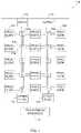
- FIG. 1illustrates an example parallel machine 100 that can be used to implement a hierarchical structure for analyzing data.
- the parallel machine 100can receive input data and provide an output based on the input data.
- the parallel machine 100can include a data input port 110 for receiving input data and an output port 114 for providing an output to another device.
- the data input port 110provides an interface for data to be input to the parallel machine 100 .
- the parallel machine 100includes a plurality of programmable elements 102 each having one or more inputs 104 and one or more outputs 106 .
- a programmable element 102can be programmed into one of a plurality of states. The state of the programmable element 102 determines what output(s) the programmable elements 102 will provide based on a given input(s). That is, the state of the programmable element 102 determines how the programmable element will react based on a given input.
- Data input to the data input port 110can be provided to the plurality of programmable elements 102 to cause the programmable elements 102 to take action thereon.
- Examples of a programmable element 102can include a state machine element (SME) discussed in detail below, and a configurable logic block.
- SMEstate machine element
- a SMEcan be set in a given state to provide a certain output (e.g., a high or “1” signal) when a given input is received at the data input port 110 .
- the SMEcan provide a different output (e.g., a low or “0” signal).
- a configurable logic blockcan be set to perform a Boolean logic function (e.g., AND, OR, NOR, ext.) based on input received at the data input port 110 .
- Boolean logic functione.g., AND, OR, NOR, ext.
- the parallel machine 100can also include a programming interface 111 for loading a program (e.g., an image) onto the parallel machine 100 .
- the imagecan program (e.g., set) the state of the programmable elements 102 . That is, the image can configure the programmable elements 102 to react in a certain way to a given input. For example, a programmable element 102 can be set to output a high signal when the character ‘a’ is received at the data input port 110 .
- the parallel machine 100can use a clock signal for controlling the timing of operation of the programmable elements 102 .
- the parallel machine 100can include special purpose elements 112 (e.g., RAM, logic gates, counters, look-up tables, etc.) for interacting with the programmable elements 102 , and for performing special purpose functions.
- the data received at the data input port 110can include a fixed set of data received over time or all at once, or a stream of data received over time. The data may be received from, or generated by, any source, such as databases, sensors, networks, etc., coupled to the parallel machine 100 .
- the parallel machine 100also includes a plurality of programmable switches 108 for selectively coupling together different elements (e.g., programmable element 102 , data input port 110 , output port 114 , programming interface 111 , and special purpose elements 112 ) of the parallel machine 100 . Accordingly, the parallel machine 100 comprises a programmable matrix formed among the elements.
- a programmable switch 108can selectively couple two or more elements to one another such that an input 104 of a programmable element 102 , the data input port 110 , a programming interface 111 , or special purpose element 112 can be coupled through one or more programmable switches 108 to an output 106 of a programmable element 102 , the output port 114 , a programming interface 111 , or special purpose element 112 .
- the routing of signals between the elementscan be controlled by setting the programmable switches 108 .
- FIG. 1illustrates a certain number of conductors (e.g., wires) between a given element and a programmable switch 108 , it should be understood that in other examples, a different number of conductors can be used. Also, although FIG. 1 illustrates each programmable element 102 individually coupled to a programmable switch 108 , in other examples, multiple programmable elements 102 can be coupled as a group (e.g., a block 802 , as illustrated in FIG. 8 ) to a programmable switch 108 .
- the data input port 110 , the data output port 114 , and/or the programming interface 111can be implemented as registers such that writing to the registers provides data to or from the respective elements.
- a single parallel machine 100is implemented on a physical device, however, in other examples two or more parallel machines 100 can be implemented on a single physical device (e.g., physical chip).
- each of multiple parallel machines 100can include a distinct data input port 110 , a distinct output port 114 , a distinct programming interface 111 , and a distinct set of programmable elements 102 .
- each set of programmable elements 102can react (e.g., output a high or low signal) to data at their corresponding input data port 110 .
- a first set of programmable elements 102 corresponding to a first parallel machine 100can react to the data at a first data input port 110 corresponding to the first parallel machine 100 .
- a second set of programmable elements 102 corresponding to a second parallel machine 100can react to a second data input port 110 corresponding to the second parallel machine 100 .
- each parallel machine 100includes a set of programmable elements 102 , wherein different sets of programmable elements 102 can react to different input data.
- each parallel machine 100 , and each corresponding set of programmable elements 102can provide a distinct output.
- an output port 114 from first parallel machine 100can be coupled to an input port 110 of a second parallel machine 100 , such that input data for the second parallel machine 100 can include the output data from the first parallel machine 100 .
- an image for loading onto the parallel machine 100comprises a plurality of bits of information for setting the state of the programmable elements 102 , programming the programmable switches 108 , and configuring the special purpose elements 112 within the parallel machine 100 .
- the imagecan be loaded onto the parallel machine 100 to program the parallel machine 100 to provide a desired output based on certain inputs.
- the output port 114can provide outputs from the parallel machine 100 based on the reaction of the programmable elements 102 to data at the data input port 110 .
- An output from the output port 114can include a single bit indicating a match of a given pattern, a word comprising a plurality of bits indicating matches and non-matches to a plurality of patterns, and a state vector corresponding to the state of all or certain programmable elements 102 at a given moment.
- Example uses for the parallel machine 100include, pattern-recognition (e.g., speech recognition, image recognition, etc.) signal processing, imaging, computer vision, cryptography, and others.
- the parallel machine 100can comprise a finite state machine (FSM) engine, a field programmable gate array (FPGA), and variations thereof.
- the parallel machine 100may be a component in a larger device such as a computer, pager, cellular phone, personal organizer, portable audio player, network device (e.g., router, firewall, switch, or any combination thereof), control circuit, camera, etc.
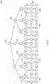
- FIG. 2illustrates an example model of a finite state machine (FSM) that can be implemented by the parallel machine 100 .
- the parallel machine 100can be configured (e.g., programmed) as a physical implementation of a FSM.
- a FSMcan be represented as a graph 200 , (e.g., directed graph, undirected graph, pseudograph), which contains one or more root nodes 202 .
- the FSMcan be made up of several standard nodes 204 and terminal nodes 208 that are connected to the root nodes 202 and other standard nodes 204 through one or more edges 206 .
- a node 202 , 204 , 208corresponds to a state in the FSM.
- the edges 206correspond to the transitions between the states.
- Each of the nodes ( 202 , 204 , 208 )can be in either an active or an inactive state. When in the inactive state, a node ( 202 , 204 , 208 ) does not react (e.g., respond) to input data. When in an active state, a node ( 202 , 204 , 208 ) can react to input data. An upstream node ( 202 , 204 ) can react to the input data by activating a node ( 204 , 208 ) that is downstream from the node when the input data matches criteria specified by an edge 206 between the upstream node ( 202 , 204 ) and the downstream node ( 204 , 208 ).
- a first node 204 that specifies the character ‘b’will activate a second node 204 connected to the first node 204 by an edge 206 when the first node 204 is active and the character ‘b’ is received as input data.
- a “upstream”refers to a relationship between one or more nodes, where a first node that is upstream of one or more other nodes (or upstream of itself in the case of loop) refers to the situation in which the first node can activate the one or more other nodes (or can activate itself in the case of a loop).
- downstreamrefers to a relationship where a first node that is downstream of one or more other nodes (of downstream of itself in the case of a loop) can be activated by the one or more other node (or can be activated by itself in the case of a loop. Accordingly, the terms “upstream” and “downstream” are used herein to refer to relationships between one or more nodes, but these terms do not preclude the use of loops or other non-linear paths among the nodes.
- the root node 202can be initially activated and can activate downstream nodes 204 , 208 when the input data matches an edge 206 from the root node 202 .
- Nodes 204 , 208 throughout the graph 200can be activated in this manner as the input data is received.
- a terminal node 208corresponds to a match of a sequence of interest by the input data. Accordingly, activation of a terminal node 208 indicates that a sequence of interest has been received as the input data.
- arriving at a terminal node 208can indicate that a specific pattern of interest has been detected in the input data.
- each root node 202 , standard node 204 , and terminal node 208can correspond to a programmable element 102 in the parallel machine 100 .
- Each edge 206can correspond to connections between the programmable elements 102 .
- a standard node 204 that transitions to (e.g., has an edge 206 connecting to) another standard node 204 or a terminal node 208corresponds to a programmable element 102 that transitions to (e.g., provides an output to) another programmable element 102 .
- the root node 202does not have a corresponding programmable element 102 .
- each of the programmable elements 102can also be in either an active or inactive state.
- a given programmable element 102 when inactivedoes not react to the input data at its corresponding data input port 110 .
- An active programmable element 102can react to the input data and the data input port 110 , and can activate a downstream programmable element 102 when the input data matches the setting of the programmable element 102 .
- the programmable element 102can be coupled to the output port 114 to provide an indication of a match to an external device.
- An image loaded onto the parallel machine 100 via the programming interface 111can configure the programmable elements 102 and other elements 112 , as well as the connections between the programmable elements 102 and other elements 112 such that a desired FSM is implemented through the sequential activation of nodes based on reactions to the data at the data input port 110 .
- a programmable element 102remains active for a single data cycle (e.g., a single character, a set of characters, a single clock cycle) and then switches to inactive unless re-activated by an upstream programmable element 102 .
- a terminal node 208can be considered to store a compressed history of past events.
- the one or more patterns of input data required to reach a terminal node 208can be represented by the activation of that terminal node 208 .
- the output provided by a terminal node 208is binary, that is, the output indicates whether the pattern of interest has been matched or not.
- the ratio of terminal nodes 208 to standard nodes 204 in a graph 200may be quite small. In other words, although there may be a high complexity in the FSM, the output of the FSM may be small by comparison.
- the output of the parallel machine 100can comprise a state vector for a parallel machine.
- the state vectorcomprises the state (e.g., activated or not activated) of programmable elements 102 of the parallel machine 100 .
- the state vectorincludes the states for the programmable elements 102 corresponding to terminal nodes 208 .
- the outputcan include a collection of the indications provided by all terminal nodes 208 of a graph 200 .
- the state vectorcan be represented as a word, where the binary indication provided by each terminal node 208 comprises one bit of the word. This encoding of the terminal nodes 208 can provide an effective indication of the detection state (e.g., whether and what sequences of interest have been detected) for the parallel machine 100 .
- the state vectorcan include the state of all or a subset of the programmable elements 102 whether or not the programmable elements 102 corresponds to a terminal node 208 .
- the parallel machine 100can be programmed to implement a pattern recognition function.
- the FSM implemented by the parallel machine 100can be configured to recognize one or more data sequences (e.g., signatures, patterns) in the input data.
- data sequencese.g., signatures, patterns
- an indication of that recognitioncan be provided at the output port 114 .
- the pattern recognitioncan recognize a string of symbols (e.g., ASCII characters) to, for example, identify malware or other information in network data.
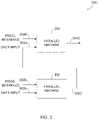
- FIG. 3illustrates an example of a first parallel machine 302 and a second parallel machine 304 configured to analyze data using a hierarchical structure 300 .
- Each parallel machine 302 , 304includes a data input port 302 A, 304 A, a programming interface 302 B, 304 B, and an output port 302 C, 304 C.
- the first parallel machine 302is configured to receive input data, for example, raw data at the data input port 302 A.
- the first parallel machine 302responds to the input data as described above and provides an output at the output port 302 C.
- the output from the first parallel machine 302is sent to the data input port 304 A of the second parallel machine 304 .
- the second parallel machine 304can then react based on the output provided by the first parallel machine 302 and provide a corresponding output at output port 304 C.
- This hierarchical coupling of two parallel machines 302 , 304 in seriesprovides a means to transfer information regarding past events in a compressed word from a first parallel machine 302 to a second parallel machine 304 .
- the information transferredcan effectively be a summary of complex events (e.g., sequences of interest) that were recorded by the first parallel machine 302 .
- the two-level hierarchy 300 of parallel machines 302 , 304 shown in FIG. 3allows two independent programs to operate based on the same data stream.
- the two stage hierarchycan be similar to visual recognition in a biological brain which is modeled as different regions. Under this model, the regions are effectively different pattern recognition engines, each performing a similar computational function (pattern matching) but using different programs (signatures). By connecting multiple parallel machines 302 , 304 together increased knowledge about the data stream input may be obtained.
- the first level of the hierarchy(implemented by the first parallel machine 302 ) performs processing directly on a raw data stream. That is, the raw data stream is received at the input interface 302 A and the programmable elements of the first parallel machine 302 can react to the raw data stream.
- the second level(implemented by the second parallel machine 304 ) of the hierarchy processes the output from the first level. That is, the second parallel machine 304 receives the output from the first parallel machine 302 at the input interface 304 B and the programmable elements of the second parallel machine 304 can react to the output of the first parallel machine 302 .
- the second parallel machine 304does not receive the raw data stream as an input, but rather receives the indications of patterns of interest that are matched by the raw data stream as determined by the first parallel machine 302 .
- the second parallel machine 304can be programmed with a FSM that recognizes patterns in the output data stream from the first parallel machine 302 .
- FIG. 4illustrates another example of a two-level hierarchy 400 , where one level of the hierarchy is implemented with multiple parallel machines.
- the first level of the hierarchy 400is implemented with three parallel machines 402 .
- the output from each of the three first level parallel machines 402is provided to a single second level parallel machine 404 that recognizes (e.g., identifies) patterns in the outputs from the first level parallel machines 402 .
- different numbers of parallel machinescan be implemented at different levels.
- Each parallel machine 402 , 404includes a data input port 402 A, 404 A, a programming interface 402 B, 404 B, and an output port 402 C, 404 C.
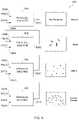
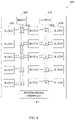
- FIG. 5illustrates a four-level hierarchy 500 implemented with four parallel machines 502 , 504 , 506 , and 508 , and showing an example of patterns to be identified by each level.
- each parallel machine 502 , 504 , 506 , and 508includes a data input port 502 A, 504 A, 506 A, and 508 A, a programming interface 502 B, 504 B, 506 B, and 508 B, and an output port 502 C, 504 C, 506 C, and 508 C.
- the four-level hierarchy 500corresponds to a visual identification of written language based on black or white pixels in an image. As the hierarchy progresses to higher levels, the accumulated knowledge of the input stream grows correspondingly.
- the parallel machines 502 , 504 , 506 , 508are cascaded to accomplish hierarchical recognition capability.
- Each successive level of the hierarchy 500can implement new rules (pattern signatures) that are applied to the compressed output of the previous level. In this way, highly detailed objects can be identified based on the initial detection of basic primitive information.
- the raw data input stream to level onecan comprise pixel information (e.g., whether a given bit is black/white, ON/OFF) for a visual image.
- the first parallel machine 502can be programmed to identify primitive patterns formed by the pixel information.
- the first parallel machine 502can be configured to identify when adjacent pixels form vertical lines, horizontal lines, arcs, etc. Each of these patterns (e.g., vertical line, horizontal line arc, etc.) can be indicated by a respective output bit (or signal) from the first parallel machine 502 .
- a high signal(e.g., logical ‘1’) can be output on a first bit of an output word to the second parallel machine 504 .
- a high signalcan be output on a second bit of an output word to the second parallel machine 504 .
- the second levelcan be programmed to identify patterns in the output signal from the first parallel machine 502 .
- the second parallel machine 502can be programmed to identify patterns formed by combinations of the primitive patterns (lines, arcs, etc.) identified by the first parallel machine 502 .
- the second parallel machine 504can be programmed to identify when a horizontal line and a vertical line cross forming the letter “t”.
- the nodes in the FSM implemented by the second parallel machine 504react to the output from the first parallel machine 502 .
- the combinations of the primitive patternsare identified by identifying patterns in the output bits from the first parallel machine 502 .
- the output from the second parallel machine 504is then input into the third level (the third parallel machine 506 ) which can identify words from combinations of the letters identified by the second parallel machine 506 .
- the fourth level (the fourth parallel machine 508 )can then identify phrases formed by the words identified by the third parallel machine 506 . Accordingly, higher levels can be programmed to identify patterns in the lower level outputs. Additionally, lower levels can be programmed to identify components that make up the patterns identified in the higher level.
- Hierarchical analysiscan be used on data corresponding to sounds to identify syllables from combinations of phonemes at a first level and words from combinations of syllables at a second level.
- the hierarchical analysiscan be applied to machine data (e.g., raw 0s and 1s) that builds upon itself in a hierarchal manner.
- FIG. 5illustrates specific and individual connections between layers
- a hierarchycan be implemented in which the output from one level is fed forward or back to other levels of the hierarchy.
- an output from the second parallel machine 504could be sent to the fourth parallel machine 508
- an output from the fourth parallel machine 508might be fed back to the third parallel machine 506 .
- a hierarchycan be implemented such that detection state information from parallel machines is fed to one or more or all of the other parallel machines.
- feedbackis used in the hierarchical structure to update the program used by one or more levels.
- an output from a first levelcan be provided to a second level to reprogram the second level. This can be used to update the rules applied by the second level based on patterns identified (or not identified) in the first level.
- the first levelis a higher level in the hierarchy than the second level.
- the lower levelfor example, can be reprogrammed to look for additional patterns not originally specified by the program based on the patterns identified by the higher level.
- the lower levelcan be notified that a particular pattern identified by the lower level is significant in that the particular pattern combines with other patterns to form a significant event.
- the lower levelmay be notified that a particular pattern identified has no particular value and, as such, the lower level can stop identifying that pattern.
- the reprogrammingcan be performed over time, such that the program for a given level is incrementally modified by small adjustments over a period of time.
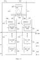
- FIG. 6illustrates an example of a four-level hierarchy 600 that uses feedback to reprogram portions of the hierarchy.
- the four-level hierarchy 600is implemented with four parallel machines 602 , 604 , 606 , 608 which each have a data input port 602 A, 604 A, 606 A, 608 A, a programming interface 602 B, 604 B, 606 C, 608 B, and an output port 602 C, 604 C, 606 C, 608 C.
- the first parallel machine 602implements the first level of the hierarchy 600 and provides an output to the second parallel machine 604 which implements the second level of the hierarchy 600 .
- the third and fourth parallel machines 606 , 608likewise implement the third and fourth levels of the hierarchy 600 .
- the output from the fourth parallel machine 608is sent to an external device as an output of the hierarchy 600 based on analysis of the hierarchy 600 on the input data received by the first parallel machine 602 . Accordingly, the output from the fourth parallel machine 608 corresponds to the collective output for the hierarchy 600 . In other examples, the output from other parallel machines 608 can correspond to the collective output for the hierarchy 600 .
- the outputs from the second, third, and fourth parallel machines 604 , 606 , 608are each fed back to the programming interface 602 B, 604 B, 606 B of the parallel machine 602 , 604 , 606 at the level below.
- the output from the fourth parallel machine 608is fed back into the programming interface 606 B of the third parallel machine 606 .
- the third parallel machine 606therefore, can be reprogrammed based on the output from the fourth parallel machine 608 .
- the third parallel machine 608can modify its program during runtime.
- the first and second parallel machines 602 , 604can be similarly reprogrammed during runtime based on the outputs from the second and third parallel machines 604 , 606 respectively.
- the feedback from a parallel machine 604 , 606 , 608is analyzed and compiled to form a program (e.g., an image) for reprogramming a parallel machine 602 , 604 , 606 .
- a programe.g., an image
- the output from the parallel machine 408is analyzed and compiled by a processing device 614 before being sent to the programming interface 606 B.
- the processing device 614can generate the updated program for the parallel machine 606 based on the output from the parallel machine 608 .
- the processing device 614can analyze the output and compile the updated program for the third parallel machine 606 .
- the updated programcan then be loaded onto the third parallel machine 606 through the programming interface 606 B to reprogram the third parallel machine 606 .
- the updated programmay contain only a partial change from the current program.
- an updated programreplaces only a portion of a current program on a parallel machine 602 , 604 , 606 , 608 .
- an updated programreplaces all or a large portion of a current program.
- the processing devices 610 , 612can analyze the feedback and compile the updated program in a similar manner based on the outputs from the second and third parallel machines 604 , 606 .
- a processing device 610 , 612 , 614can be implemented with one or more additional parallel machines, or can be implemented with a different type of machine (e.g., a computer having a von Neumann architecture).
- the processing device 610 , 612 , 614analyzes the output from a higher level prior to compiling the new program. In an example, the processing device 610 , 612 , 614 analyses the output to determine how to update the lower level program and then compiles the new (e.g., updated, original) lower level program based on the analysis.
- the feedback at a given parallel machineis received from the level directly above the given parallel machine, feedback can be from any parallel machine to another parallel machine at a higher, lower, or the same level.
- feedbackcan be received at a programming input of a parallel machine from the output of that same parallel machine, or from the output of another parallel machine at the same, higher, or lower levels.
- a parallel machinecan receive feedback from multiple different parallel machines. The reprogramming of parallel machines based on feedback may be disconnected in time from the identification of patterns in the input data (e.g., not real time with the processing of the raw data).
- a purpose of sending information back down the hierarchy to affect reprogramming of the lower levelscan be so that the lower levels may become more efficient at discerning patterns of interest.
- Another purpose for sending information down the hierarchyis to achieve a higher level of acuity in the lower levels.
- the process of sending information to higher levelsis avoided when possible, recognizing that it takes time to transfer information to higher levels of the hierarchy.
- the higher levelscan be essentially used to resolve the identification of patterns that are new to the system. This can be similar to the process used that takes place in the neocortex of a biological brain. In an example, if a pattern can be fully resolved at the lower levels, it should be.
- the feedback mechanismis one method to transfer “learning” to the lower levels of the hierarchy. This process of pushing information back down the hierarchy will help preserve the upper levels of the hierarchy for processing new or unfamiliar patterns. Furthermore, the entire recognition process can speed up by reducing the amount of data transfer through various levels of the hierarchy.
- the feedbackcan make the lower levels of the hierarchy more acutely sensitive to the data stream at the input.
- a consequence of this “push down” of informationis that decisions can be made at the lower levels of the hierarchy and can be done so quickly.
- the output from lower level parallel machinese.g., the first parallel machine 602
- the external devicecan, for example, monitor the output from each of these parallel machines 602 , 608 to determine when patterns have been identified by the hierarchy 600 .
- the feedback informationcan include identifying information corresponding to the data stream analyzed.
- the identifying informationcan include an identifying characteristic of the data, format of the data, a protocol of the data, and/or any other type of identifying information.
- the identifying informationmay be collected, analyzed, and used to modify (e.g., adapt) the analysis method for the input data by, for example the processing device 610 .
- a parallel machine 100may then be programmed with the adapted analysis method.
- the identifying informationcan include, for example, a language of the input data.
- the parallel machine 100can be initially programmed to determine a language of the input data and may be adapted (e.g., reprogrammed) during runtime once a language has been identified corresponding to the input.
- the adapted analysis method for the parallel machine 100can correspond more specifically to analysis methods for the identified language.
- the parallel machine 100may analyze future input data using the adapted analysis method.
- the feedback processmay be iterative, so that additional identifying information may be found in the input data to allow for further adaptation of the analysis method.
- Programsfor loading onto a parallel machine 100 can be generated by a compiler as discussed below with respect to FIG. 12 .
- compilingcan be a computationally intensive process, and can be most apparent when compiling large databases of pattern signatures for the first time.
- parallel machines 100 of higher levelscan be providing feedback to the lower levels in the form of an incremental program update for the lower level parallel machine.
- the feedback information to the lower level parallel machinecan be much smaller, incremental updates to an original program that are less computationally intensive to compile.
- FIG. 7illustrates another example of a four-level hierarchy 700 implemented with four parallel machines 702 , 704 , 706 , 708 .
- the four parallel machines 702 , 704 , 706 , 708which each have a data input port 702 A, 704 A, 706 A, 708 A, a programming interface 702 B, 704 B, 706 C, 708 B, and an output port 702 C, 704 C, 706 C, 708 C.
- the four-level hierarchy 700can include processing devices 710 , 712 , 714 to compile programs for the parallel machines 702 , 704 , and 706 .
- the second, third, and fourth level parallel machines 704 , 706 , 708receive input data from outputs of lower level parallel machines 702 , 704 , 706 as well as the input data from the raw data stream. Accordingly, the levels two, three, and four can identify patterns from combinations of the patterns from lower levels and the raw data.
- parallel machines 100can be cascaded in almost any manner where the raw data input to the hierarchy as well as an output from a parallel machine 100 can be sent to any other parallel machine 100 including itself. Moreover, the outputs from a given parallel machine 100 can be sent to another parallel machine 100 as input data in to the data input port 110 and/or as feedback for updating the program for a parallel machine 100 .
- cascading parallel machines 100 in seriescan increase the time to fully process the input data stream through all the parallel machines 100 to generate a collective output for a hierarchy. Since the lower level of a hierarchy can receive a lower (most granular) level of input, the lower levels should be expected to be more active than the output of high levels. That is, each successive level in the hierarchy can assemble higher level objects.
- a parallel machine 100has a maximum input rate that limits how fast input data can be fed to the parallel machine 100 . This input rate can be thought of as a single data cycle. On each successive data cycle the parallel machine 100 has the potential to activate many terminal nodes.
- a parallel machine 100(especially at the lower levels of a hierarchy) to produce a significant amount of output data. For example, if the input is provided as stream of bytes to the lowest level parallel machine 100 , on any given data cycle it may be possible for the parallel machine 100 to generate multiple bytes of result information. If one byte of information can generate multiple bytes of information, then the entire hierarchy of parallel machines 100 should be synchronized so that information is passed up the hierarchy. In some examples, the feedback does not need to be synchronized. The faster the feedback is received at a lower level, however, the faster the lower level can adapt, and the more efficient the analysis.
- a maximum size output for each level of the hierarchycan equal 1024 bytes and a depth of the hierarchy can equal 4 levels.
- the input data stream data rate for a parallel machine 100can equal 128 MB/second. With these conditions each level of the hierarchy could be traversed in 7.63 microseconds. With a four level hierarchy, the total settling time of the entire stack of parallel machines 100 would be 4 times 7.63 microseconds or 30.5 microseconds. With a 30.5 microsecond settling time, the implication is that the input data frequency should be limited to 32 KB/s.
- Parallel machines 100can be configurable to tradeoff input data rates vs. the state machine size.
- the input word size to a parallel machinecan be adjusted if corresponding modifications are made to the compiler that produced the individual images loaded onto the parallel machines 100 .
- the hierarchical structure described abovecould be implemented with software on machine having a von Neumann architecture. Accordingly, software instructions could cause a processor to implement a first level analysis FSM on raw data. The output from the first level FSM could then be processed by the processor using a second level analysis and so on. Moreover, the feedback loop discussed above could be implemented such that the first level analysis is modified based on, for example, the output of the second level analysis.
- FIGS. 8-11illustrate an example of a parallel machine referred to herein as “FSM engine 800 ”.
- the FSM engine 800comprises a hardware implementation of a finite state machine.
- the FSM engine 800implements a plurality of selectively coupleable hardware elements (e.g., programmable elements) that correspond to a plurality of states in a FSM. Similar to a state in a FSM, a hardware element can analyze an input stream and activate a downstream hardware element based on the input stream.
- the FSM engine 800includes a plurality of programmable elements including general purpose elements and special purpose elements.
- the general purpose elementscan be programmed to implement many different functions. These general purpose elements include SMEs 804 , 805 (shown in FIG. 11 ) that are hierarchically organized into rows 806 (shown in FIGS. 9 and 10 ) and blocks 802 (shown in FIGS. 8 and 9 ).
- SMEs 804 , 805shown in FIG. 11
- rows 806shown in FIGS. 9 and 10
- blocks 802shown in FIGS. 8 and 9
- a SME 804 , 805can correspond to a state of a FSM implemented by the FSM engine 800 .
- the SMEs 804 , 805can be coupled together by using the programmable switches as described below. Accordingly, a FSM can be implemented on the FSM engine 800 by programming the SMEs 804 , 805 to correspond to the functions of states and by selectively coupling together the SMEs 804 , 805 to correspond to the transitions between states in the FSM.
- FIG. 8illustrates an overall view of an example FSM engine 800 .
- the FSM engine 800includes a plurality of blocks 802 that can be selectively coupled together with programmable inter-block switches 803 . Additionally, the blocks 802 can be selectively coupled to an input block 809 (e.g., a data input port) for receiving signals (e.g., data) and providing the data to the blocks 802 .
- the blocks 802can also be selectively coupled to an output block 813 (e.g., an output port) for providing signals from the blocks 802 to an external device (e.g., another FSM engine 800 ).
- the FSM engine 800can also include a programming interface 811 to load a program (e.g., an image) onto the FSM engine 800 .
- the imagecan program (e.g., set) the state of the SMEs 804 , 805 . That is, the image can configure the SMEs 804 , 805 to react in a certain way to a given input at the input block 809 .
- a SME 804can be set to output a high signal when the character ‘a’ is received at the input block 809 .
- the input block 809 , the output block 813 , and/or the programming interface 811can be implemented as registers such that writing to the registers provides data to or from the respective elements. Accordingly, bits from the image stored in the registers corresponding to the programming interface 811 can be loaded on the SMEs 804 , 805 .
- FIG. 8illustrates a certain number of conductors (e.g., wire, trace) between a block 802 , input block 809 , output block 813 , and an inter-block switch 803 , it should be understood that in other examples, fewer or more conductors can be used.
- FIG. 9illustrates an example of a block 802 .
- a block 802can include a plurality of rows 806 that can be selectively coupled together with programmable intra-block switches 808 . Additionally, a row 806 can be selectively coupled to another row 806 within another block 802 with the inter-block switches 803 .
- buffers 801are included to control the timing of signals to/from the inter-block switches 803 .
- a row 806includes a plurality of SMEs 804 , 805 organized into pairs of elements that are referred to herein as groups of two (GOTs) 810 .
- a block 802comprises sixteen (16) rows 806 .
- FIG. 10illustrates an example of a row 806 .
- a GOT 810can be selectively coupled to other GOTs 810 and any other elements 824 within the row 806 by programmable intra-row switches 812 .
- a GOT 810can also be coupled to other GOTs 810 in other rows 806 with the intra-block switch 808 , or other GOTs 810 in other blocks 802 with an inter-block switch 803 .
- a GOT 810has a first and second input 814 , 816 , and an output 818 .
- the first input 814is coupled to a first SME 804 of the GOT 810 and the second input 814 is coupled to a second SME 804 of the GOT 810 .
- the row 806includes a first and second plurality of row interconnection conductors 820 , 822 .
- an input 814 , 816 of a GOT 810can be coupled to one or more row interconnection conductors 820 , 822 , and an output 818 can be coupled to one row interconnection conductor 820 , 822 .
- a first plurality of the row interconnection conductors 820can be coupled to each SME 804 of each GOT 810 within the row 806 .
- a second plurality of the row interconnection conductors 822can be coupled to one SME 804 of each GOT 810 within the row 806 , but cannot be coupled to the other SME 804 of the GOT 810 .
- a first half of the second plurality of row interconnection conductors 822can couple to first half of the SMEs 804 within a row 806 (one SME 804 from each GOT 810 ) and a second half of the second plurality of row interconnection conductors 822 can couple to a second half of the SMEs 804 within a row 806 (the other SME 804 from each GOT 810 ).
- the limited connectivity between the second plurality of row interconnection conductors 822 and the SMEs 804 , 805is referred to herein as “parity”.
- the row 806can also include a special purpose element 824 such as a counter, a programmable Boolean logic element, a field programmable gate array (FPGA), an application specific integrated circuit (ASIC), a programmable processor (e.g., a microprocessor), and other elements.
- a special purpose element 824such as a counter, a programmable Boolean logic element, a field programmable gate array (FPGA), an application specific integrated circuit (ASIC), a programmable processor (e.g., a microprocessor), and other elements.
- the special purpose element 824includes a counter (also referred to herein as counter 824 ).
- the counter 824comprises a 12-bit programmable down counter.
- the 12-bit programmable counter 824has a counting input, a reset input, and zero-count output.
- the counting inputwhen asserted, decrements the value of the counter 824 by one.
- the reset inputwhen asserted, causes the counter 824 to load an initial value from an associated register.
- up to a 12-bit numbercan be loaded in as the initial value.
- the zero-count outputis asserted.
- the counter 824also has at least two modes, pulse and hold.
- the special purpose element 824includes Boolean logic. In some examples, this Boolean logic can be used to extract information from terminal state SMEs in FSM engine 800 . The information extracted can be used to transfer state information to other FSM engines 800 and/or to transfer programming information used to reprogram FSM engine 800 , or to reprogram another FSM engine 800 .
- FIG. 11illustrates an example of a GOT 810 .
- the GOT 810includes a first SME 804 and a second SME 805 having inputs 814 , 816 and having their outputs 826 , 828 coupled to an OR gate 830 and a 3-to-1 multiplexer 842 .
- the 3-to-1 multiplexer 842can be set to couple the output 818 of the GOT 810 to either the first SME 804 , the second SME 805 , or the OR gate 830 .
- the OR gate 830can be used to couple together both outputs 826 , 828 to form the common output 818 of the GOT 810 .
- the first and second SME 804 , 805exhibit parity, as discussed above, where the input 814 of the first SME 804 can be coupled to some of the row interconnect conductors 822 and the input 816 of the second SME 805 can be coupled to other row interconnect conductors 822 .
- the two SMEs 804 , 805 within a GOT 810can be cascaded and/or looped back to themselves by setting either or both of switches 840 .
- the SMEs 804 , 805can be cascaded by coupling the output 826 , 828 of the SMEs 804 , 805 to the input 814 , 816 of the other SME 804 , 805 .
- the SMEs 804 , 805can be looped back to themselves by coupling the output 826 , 828 to their own input 814 , 816 . Accordingly, the output 826 of the first SME 804 can be coupled to neither, one, or both of the input 814 of the first SME 804 and the input 816 of the second SME 805 .
- a state machine element 804 , 805comprises a plurality of memory cells 832 , such as those often used in dynamic random access memory (DRAM), coupled in parallel to a detect line 834 .
- One such memory cell 832comprises a memory cell that can be set to a data state, such as one that corresponds to either a high or a low value (e.g., a 1 or 0).
- the output of the memory cell 832is coupled to the detect line 834 and the input to the memory cell 832 receives signals based on data on the data stream line 836 .
- an input on the data stream line 836is decoded to select one of the memory cells 832 .
- the selected memory cell 832provides its stored data state as an output onto the detect line 834 .
- the data received at the data input port 809can be provided to a decoder (not shown) and the decoder can select one of the data stream lines 836 .
- the decodercan convert an ACSII character to 1 of 256 bits.
- a memory cell 832therefore, outputs a high signal to the detect line 834 when the memory cell 832 is set to a high value and the data on the data stream line 836 corresponds to the memory cell 832 .
- the memory cell 832outputs a low signal to the detect line 834 .
- the outputs from the memory cells 832 on the detect line 834are sensed by a detect circuit 838 .
- the signal on an input line 814 , 816sets the respective detect circuit 838 to either an active or inactive state.
- the detect circuit 838When set to the inactive state, the detect circuit 838 outputs a low signal on the respective output 826 , 828 regardless of the signal on the respective detect line 834 .
- the detect circuit 838When set to an active state, the detect circuit 838 outputs a high signal on the respective output line 826 , 828 when a high signal is detected from one of the memory cells 834 of the respective SME 804 , 805 .
- the detect circuit 838When in the active state, the detect circuit 838 outputs a low signal on the respective output line 826 , 828 when the signals from all of the memory cells 834 of the respective SME 804 , 805 are low.
- an SME 804 , 805includes 256 memory cells 832 and each memory cell 832 is coupled to a different data stream line 836 .
- an SME 804 , 805can be programmed to output a high signal when a selected one or more of the data stream lines 836 have a high signal thereon.
- the SME 804can have a first memory cell 832 (e.g., bit 0 ) set high and all other memory cells 832 (e.g., bits 1 - 255 ) set low.
- the SME 804outputs a high signal on the output 826 when the data stream line 836 corresponding to bit 0 has a high signal thereon.
- the SME 804can be set to output a high signal when one of multiple data stream lines 836 have a high signal thereon by setting the appropriate memory cells 832 to a high value.
- a memory cell 832can be set to a high or low value by reading bits from an associated register.
- the SMEs 804can be programmed by storing an image created by the compiler into the registers and loading the bits in the registers into associated memory cells 832 .
- the image created by the compilerincludes a binary image of high and low (e.g., 1 and 0 ) bits.
- the imagecan program the FSM engine 800 to operate as a FSM by cascading the SMEs 804 , 805 .
- a first SME 804can be set to an active state by setting the detect circuit 838 to the active state.
- the first SME 804can be set to output a high signal when the data stream line 836 corresponding to bit 0 has a high signal thereon.
- the second SME 805can be initially set to an inactive state, but can be set to, when active, output a high signal when the data stream line 836 corresponding to bit 1 has a high signal thereon.
- the first SME 804 and the second SME 805can be cascaded by setting the output 826 of the first SME 804 to couple to the input 816 of the second SME 805 .
- the first SME 804when a high signal is sensed on the data stream line 836 corresponding to bit 0 , the first SME 804 outputs a high signal on the output 826 and sets the detect circuit 838 of the second SME 805 to an active state.
- the second SME 805When a high signal is sensed on the data stream line 836 corresponding to bit 1 , the second SME 805 outputs a high signal on the output 828 to activate another SME 805 or for output from the FSM engine 800 .
- FIG. 10illustrates an example of a method 1000 for a compiler to convert source code into an image configured to program a parallel machine.
- Method 1000includes parsing the source code into a syntax tree (block 1002 ), converting the syntax tree into an automaton (block 1004 ), optimizing the automaton (block 1006 ), converting the automaton into a netlist (block 1008 ), placing the netlist on hardware (block 1010 ), routing the netlist (block 1012 ), and publishing the resulting image (block 1014 ).
- the compilerincludes an application programming interface (API) that allows software developers to create images for implementing FSMs on the FSM engine 800 .
- the compilerprovides methods to convert an input set of regular expressions in the source code into an image that is configured to program the FSM engine 800 .
- the compilercan be implemented by instructions for a computer having a von Neumann architecture. These instructions can cause a processor on the computer to implement the functions of the compiler. For example, the instructions, when executed by the processor, can cause the processor to perform actions as described in blocks 1002 , 1004 , 1006 , 1008 , 1010 , 1012 , and 1014 on source code that is accessible to the processor.
- An example computer having a von Neumann architectureis shown in FIG. 13 and described below.
- the source codedescribes search strings for identifying patterns of symbols within a group of symbols.
- the source codecan include a plurality of regular expressions (regexs).
- a regexcan be a string for describing a symbol search pattern.
- Regexesare widely used in various computer domains, such as programming languages, text editors, network security, and others.
- the regular expressions supported by the compilerinclude search criteria for the search of unstructured data. Unstructured data can include data that is free form and has no indexing applied to words within the data. Words can include any combination of bytes, printable and non-printable, within the data.
- the compilercan support multiple different source code languages for implementing regexes including Perl, (e.g., Perl compatible regular expressions (PCRE)), PHP, Java, and .NET languages.
- PCEPerl compatible regular expressions
- the compilercan parse the source code to form an arrangement of relationally connected operators, where different types of operators correspond to different functions implemented by the source code (e.g., different functions implemented by regexes in the source code).
- Parsing source codecan create a generic representation of the source code.
- the generic representationcomprises an encoded representation of the regexs in the source code in the form of a tree graph known as a syntax tree.
- the examples described hereinrefer to the arrangement as a syntax tree (also known as an “abstract syntax tree”) in other examples, however, a concrete syntax tree or other arrangement can be used.
- the compilercan support multiple languages of source code, parsing converts the source code, regardless of the language, into a non-language specific representation, e.g., a syntax tree.
- further processing(blocks 1004 , 1006 , 1008 , 1010 ) by the compiler can work from a common input structure regardless of the language of the source code.
- the syntax treeincludes a plurality of operators that are relationally connected.
- a syntax treecan include multiple different types of operators. That is, different operators can correspond to different functions implemented by the regexes in the source code.
- the syntax treeis converted into an automaton.
- An automatoncomprises a software model of a FSM and can accordingly be classified as deterministic or non-deterministic.
- a deterministic automatonhas a single path of execution at a given time, while a non-deterministic automaton has multiple concurrent paths of execution.
- the automatoncomprises a plurality of states.
- the operators and relationships between the operators in the syntax treeare converted into states with transitions between the states.
- the automatoncan be converted based partly on the hardware of the FSM engine 800 .
- input symbols for the automatoninclude the symbols of the alphabet, the numerals 0-9, and other printable characters.
- the input symbolsare represented by the byte values 0 through 255 inclusive.
- an automatoncan be represented as a directed graph where the nodes of the graph correspond to the set of states.
- a transition from state p to state q on an input symbol ⁇ , i.e. ⁇ (p, ⁇ )is shown by a directed connection from node p to node q.
- a reversal of an automatonproduces a new automaton where each transition p ⁇ q on some symbol ⁇ is reversed q ⁇ p on the same symbol.
- start statebecomes a final state and the final states become start states.
- the language accepted (e.g., matched) by an automatonis the set of all possible character strings which when input sequentially into the automaton will reach a final state. Each string in the language accepted by the automaton traces a path from the start state to one or more final states.
- the automatonis optimized to, among other things, reduce its complexity and size.
- the automatoncan be optimized by combining redundant states.
- the optimized automatonis converted into a netlist. Converting the automaton into a netlist maps each state of the automaton to a hardware element (e.g., SMEs 804 , 805 , other elements 824 ) on the FSM engine 800 , and determines the connections between the hardware elements.
- a hardware elemente.g., SMEs 804 , 805 , other elements 824
- the netlistis placed to select a specific hardware element of the target device (e.g., SMEs 804 , 805 , special purpose elements 824 ) corresponding to each node of the netlist.
- placingselects each specific hardware element based on general input and output constraints for of the FSM engine 800 .
- the placed netlistis routed to determine the settings for the programmable switches (e.g., inter-block switches 803 , intra-block switches 808 , and intra-row switches 812 ) in order to couple the selected hardware elements together to achieve the connections describe by the netlist.
- the settings for the programmable switchesare determined by determining specific conductors of the FSM engine 800 that will be used to connect the selected hardware elements, and the settings for the programmable switches. Routing can take into account more specific limitations of the connections between the hardware elements that placement at block 1010 . Accordingly, routing may adjust the location of some of the hardware elements as determined by the global placement in order to make appropriate connections given the actual limitations of the conductors on the FSM engine 800 .
- the placed and routed netlistcan be converted into a plurality of bits for programming of a FSM engine 800 .
- the plurality of bitsare referred to herein as an image.
- an imageis published by the compiler.
- the imagecomprises a plurality of bits for programming specific hardware elements and/or programmable switches of the FSM engine 800 .
- the imagecan be referred to as a binary image.
- the bitscan be loaded onto the FSM engine 800 to program the state of SMEs 804 , 805 , the special purpose elements 824 , and the programmable switches such that the programmed FSM engine 800 implements a FSM having the functionality described by the source code.
- Placement (block 1010 ) and routing (block 1012 )can map specific hardware elements at specific locations in the FSM engine 800 to specific states in the automaton.
- the bits in the imagecan program the specific hardware elements and/or programmable switches to implement the desired function(s).
- the imagecan be published by saving the machine code to a computer readable medium.
- the imagecan be published by displaying the image on a display device.
- the imagecan be published by sending the image to another device, such as a programming device for loading the image onto the FSM engine 800 .
- the imagecan be published by loading the image onto a parallel machine (e.g., the FSM engine 800 ).
- an imagecan be loaded onto the FSM engine 800 by either directly loading the bit values from the image to the SMEs 804 , 805 and other hardware elements 824 or by loading the image into one or more registers and then writing the bit values from the registers to the SMEs 804 , 805 and other hardware elements 824 .
- the state of the programmable switchese.g., inter-block switches 803 , intra-block switches 808 , and intra-row switches 812 ).
- the hardware elementse.g., SMEs 804 , 805 , other elements 824 , programmable switches 803 , 808 , 812 ) of the FSM engine 800 are memory mapped such that a programming device and/or computer can load the image onto the FSM engine 800 by writing the image to one or more memory addresses.
- Method examples described hereincan be machine or computer-implemented at least in part. Some examples can include a computer-readable medium or machine-readable medium encoded with instructions operable to configure an electronic device to perform methods as described in the above examples.
- An implementation of such methodscan include code, such as microcode, assembly language code, a higher-level language code, or the like. Such code can include computer readable instructions for performing various methods. The code may form portions of computer program products. Further, the code may be tangibly stored on one or more volatile or non-volatile computer-readable media during execution or at other times.
- These computer-readable mediamay include, but are not limited to, hard disks, removable magnetic disks, removable optical disks (e.g., compact disks and digital video disks), magnetic cassettes, memory cards or sticks, random access memories (RAMs), read only memories (ROMs), and the like.
- FIG. 13illustrates generally an example of a computer 1500 having a von Neumann architecture.
- a software programcan be launched from a computer-readable medium in a computer-based system to execute the functions defined in the software program.
- One of ordinary skill in the artwill further understand the various programming languages that can be employed to create one or more software programs designed to implement and perform the methods disclosed herein.
- the programscan be structured in an object-orientated format using an object-oriented language, such as Java, C++, or one or more other languages.
- the programscan be structured in a procedure-orientated format using a procedural language, such as assembly, C, etc.
- the software componentscan communicate using any of a number of mechanisms well known to those of ordinary skill in the art, such as application program interfaces or interprocess communication techniques, including remote procedure calls or others.
- the teachings of various embodimentsare not limited to any particular programming language or environment.
- an article of manufacturesuch as a computer, a memory system, a magnetic or optical disk, some other storage device, or any type of electronic device or system can include one or more processors 1502 coupled to a computer-readable medium 1522 such as a memory (e.g., removable storage media, as well as any memory including an electrical, optical, or electromagnetic conductor) having instructions 1524 stored thereon (e.g., computer program instructions), which when executed by the one or more processors 1502 result in performing any of the actions described with respect to the methods above.
- a computer-readable medium 1522such as a memory (e.g., removable storage media, as well as any memory including an electrical, optical, or electromagnetic conductor) having instructions 1524 stored thereon (e.g., computer program instructions), which when executed by the one or more processors 1502 result in performing any of the actions described with respect to the methods above.
- the computer 1500can take the form of a computer system having a processor 1502 coupled to a number of components directly, and/or using a bus 1508 .
- Such componentscan include main memory 1504 , static or non-volatile memory 1506 , and mass storage 1516 .
- Other components coupled to the processor 1502can include an output device 1510 , such as a video display, an input device 1512 , such as a keyboard, and a cursor control device 1514 , such as a mouse.
- a network interface device 1520 to couple the processor 1502 and other components to a network 1526can also be coupled to the bus 1508 .
- the instructions 1524can further be transmitted or received over the network 1526 via the network interface device 1520 utilizing any one of a number of well-known transfer protocols (e.g., HTTP). Any of these elements coupled to the bus 1508 can be absent, present singly, or present in plural numbers, depending on the specific embodiment to be realized.
- HTTPtransfer protocol
- one or more of the processor 1502 , the memories 1504 , 1506 , or the storage device 1516can each include instructions 1524 that, when executed, can cause the computer 1500 to perform any one or more of the methods described herein.
- the computer 1500operates as a standalone device or can be connected (e.g., networked) to other devices. In a networked environment, the computer 1500 can operate in the capacity of a server or a client device in server-client network environment, or as a peer device in a peer-to-peer (or distributed) network environment.
- the computer 1500can include a personal computer (PC), a tablet PC, a set-top box (STB), a Personal Digital Assistant (PDA), a cellular telephone, a web appliance, a network router, switch or bridge, or any device capable of executing a set of instructions (sequential or otherwise) that specify actions to be taken by that device.
- PCpersonal computer
- PDAPersonal Digital Assistant
- STBset-top box
- web applianceweb appliance
- network routerswitch or bridge
- the computer 1500can also include an output controller 1528 for communicating with peripheral devices using one or more communication protocols (e.g., universal serial bus (USB), IEEE 1394, etc.)
- the output controller 1528can, for example, provide an image to a programming device 1530 that is communicatively coupled to the computer 1500 .
- the programming device 1530can be configured to program a parallel machine (e.g., parallel machine 100 , FSM engine 800 ).
- the programming device 1530can be integrated with the computer 1500 and coupled to the bus 1508 or can communicate with the computer 1500 via the network interface device 1520 or another device.
- While the computer-readable medium 1524is shown as a single medium, the term “computer-readable medium” should be taken to include a single medium or multiple media (e.g., a centralized or distributed database, or associated caches and servers, and or a variety of storage media, such as the processor 1502 registers, memories 1504 , 1506 , and the storage device 1516 ) that store the one or more sets of instructions 1524 .
- the term “computer-readable medium”shall also be taken to include any medium that is capable of storing, encoding or carrying a set of instructions for execution by the computer and that cause the computer to perform any one or more of the methodologies of the present invention, or that is capable of storing, encoding or carrying data structures utilized by or associated with such a set of instructions.
- the term “computer-readable medium”shall accordingly be taken to include, but not be limited to tangible media, such as solid-state memories, optical, and magnetic media.
Landscapes
- Engineering & Computer Science (AREA)
- Theoretical Computer Science (AREA)
- Software Systems (AREA)
- Physics & Mathematics (AREA)
- General Physics & Mathematics (AREA)
- General Engineering & Computer Science (AREA)
- Computer Hardware Design (AREA)
- Artificial Intelligence (AREA)
- Mathematical Physics (AREA)
- Data Mining & Analysis (AREA)
- Computational Linguistics (AREA)
- Multimedia (AREA)
- Databases & Information Systems (AREA)
- Computing Systems (AREA)
- Computer Vision & Pattern Recognition (AREA)
- Medical Informatics (AREA)
- Evolutionary Computation (AREA)
- Health & Medical Sciences (AREA)
- General Health & Medical Sciences (AREA)
- Audiology, Speech & Language Pathology (AREA)
- Computer Networks & Wireless Communication (AREA)
- Image Processing (AREA)
- Devices For Executing Special Programs (AREA)
- Stored Programmes (AREA)
- Image Analysis (AREA)
- Character Discrimination (AREA)
- Analysing Materials By The Use Of Radiation (AREA)
Abstract
Description
Claims (20)
Priority Applications (2)
| Application Number | Priority Date | Filing Date | Title |
|---|---|---|---|
| US15/728,216US11488378B2 (en) | 2010-06-10 | 2017-10-09 | Analyzing data using a hierarchical structure |
| US17/977,113US12277760B2 (en) | 2010-06-10 | 2022-10-31 | Analyzing data using a hierarchical structure |
Applications Claiming Priority (4)
| Application Number | Priority Date | Filing Date | Title |
|---|---|---|---|
| US35354610P | 2010-06-10 | 2010-06-10 | |
| US12/943,551US8601013B2 (en) | 2010-06-10 | 2010-11-10 | Analyzing data using a hierarchical structure |
| US14/087,904US9785847B2 (en) | 2010-06-10 | 2013-11-22 | Analyzing data using a hierarchical structure |
| US15/728,216US11488378B2 (en) | 2010-06-10 | 2017-10-09 | Analyzing data using a hierarchical structure |
Related Parent Applications (1)
| Application Number | Title | Priority Date | Filing Date |
|---|---|---|---|
| US14/087,904ContinuationUS9785847B2 (en) | 2010-06-10 | 2013-11-22 | Analyzing data using a hierarchical structure |
Related Child Applications (1)
| Application Number | Title | Priority Date | Filing Date |
|---|---|---|---|
| US17/977,113ContinuationUS12277760B2 (en) | 2010-06-10 | 2022-10-31 | Analyzing data using a hierarchical structure |
Publications (2)
| Publication Number | Publication Date |
|---|---|
| US20180096213A1 US20180096213A1 (en) | 2018-04-05 |
| US11488378B2true US11488378B2 (en) | 2022-11-01 |
Family
ID=45097097
Family Applications (4)
| Application Number | Title | Priority Date | Filing Date |
|---|---|---|---|
| US12/943,551Active2031-05-31US8601013B2 (en) | 2010-06-10 | 2010-11-10 | Analyzing data using a hierarchical structure |
| US14/087,904Active2033-01-13US9785847B2 (en) | 2010-06-10 | 2013-11-22 | Analyzing data using a hierarchical structure |
| US15/728,216Active2034-09-22US11488378B2 (en) | 2010-06-10 | 2017-10-09 | Analyzing data using a hierarchical structure |
| US17/977,113Active2031-07-09US12277760B2 (en) | 2010-06-10 | 2022-10-31 | Analyzing data using a hierarchical structure |
Family Applications Before (2)
| Application Number | Title | Priority Date | Filing Date |
|---|---|---|---|
| US12/943,551Active2031-05-31US8601013B2 (en) | 2010-06-10 | 2010-11-10 | Analyzing data using a hierarchical structure |
| US14/087,904Active2033-01-13US9785847B2 (en) | 2010-06-10 | 2013-11-22 | Analyzing data using a hierarchical structure |
Family Applications After (1)
| Application Number | Title | Priority Date | Filing Date |
|---|---|---|---|
| US17/977,113Active2031-07-09US12277760B2 (en) | 2010-06-10 | 2022-10-31 | Analyzing data using a hierarchical structure |
Country Status (7)
| Country | Link |
|---|---|
| US (4) | US8601013B2 (en) |
| EP (1) | EP2580659B1 (en) |
| JP (1) | JP5736042B2 (en) |
| KR (1) | KR101698237B1 (en) |
| CN (2) | CN105912992B (en) |
| TW (1) | TWI584198B (en) |
| WO (1) | WO2011156634A2 (en) |
Families Citing this family (80)
| Publication number | Priority date | Publication date | Assignee | Title |
|---|---|---|---|---|
| US8938590B2 (en) | 2008-10-18 | 2015-01-20 | Micron Technology, Inc. | Indirect register access method and system |
| US8209521B2 (en) | 2008-10-18 | 2012-06-26 | Micron Technology, Inc. | Methods of indirect register access including automatic modification of a directly accessible address register |
| US7970964B2 (en) | 2008-11-05 | 2011-06-28 | Micron Technology, Inc. | Methods and systems to accomplish variable width data input |
| US7917684B2 (en) | 2008-11-05 | 2011-03-29 | Micron Technology, Inc. | Bus translator |
| US8402188B2 (en) | 2008-11-10 | 2013-03-19 | Micron Technology, Inc. | Methods and systems for devices with a self-selecting bus decoder |
| US20100138575A1 (en) | 2008-12-01 | 2010-06-03 | Micron Technology, Inc. | Devices, systems, and methods to synchronize simultaneous dma parallel processing of a single data stream by multiple devices |
| US9348784B2 (en) | 2008-12-01 | 2016-05-24 | Micron Technology, Inc. | Systems and methods for managing endian mode of a device |
| US9164945B2 (en) | 2008-12-01 | 2015-10-20 | Micron Technology, Inc. | Devices, systems, and methods to synchronize parallel processing of a single data stream |
| US8140780B2 (en) | 2008-12-31 | 2012-03-20 | Micron Technology, Inc. | Systems, methods, and devices for configuring a device |
| US8281395B2 (en) | 2009-01-07 | 2012-10-02 | Micron Technology, Inc. | Pattern-recognition processor with matching-data reporting module |
| US20100174887A1 (en) | 2009-01-07 | 2010-07-08 | Micron Technology Inc. | Buses for Pattern-Recognition Processors |
| US8214672B2 (en) | 2009-01-07 | 2012-07-03 | Micron Technology, Inc. | Method and systems for power consumption management of a pattern-recognition processor |
| US9836555B2 (en) | 2009-06-26 | 2017-12-05 | Micron Technology, Inc. | Methods and devices for saving and/or restoring a state of a pattern-recognition processor |
| US9501705B2 (en) | 2009-12-15 | 2016-11-22 | Micron Technology, Inc. | Methods and apparatuses for reducing power consumption in a pattern recognition processor |
| US9323994B2 (en) | 2009-12-15 | 2016-04-26 | Micron Technology, Inc. | Multi-level hierarchical routing matrices for pattern-recognition processors |
| US8601013B2 (en)* | 2010-06-10 | 2013-12-03 | Micron Technology, Inc. | Analyzing data using a hierarchical structure |
| US8766666B2 (en)* | 2010-06-10 | 2014-07-01 | Micron Technology, Inc. | Programmable device, hierarchical parallel machines, and methods for providing state information |
| JP5857072B2 (en) | 2011-01-25 | 2016-02-10 | マイクロン テクノロジー, インク. | Expansion of quantifiers to control the order of entry and / or exit of automata |
| JP5763783B2 (en)* | 2011-01-25 | 2015-08-12 | マイクロン テクノロジー, インク. | Method and apparatus for compiling regular expressions |
| JP5848778B2 (en) | 2011-01-25 | 2016-01-27 | マイクロン テクノロジー, インク. | Use of dedicated elements to implement FSM |
| KR101551045B1 (en) | 2011-01-25 | 2015-09-07 | 마이크론 테크놀로지, 인크. | State grouping for element utilization |
| US9047559B2 (en) | 2011-07-22 | 2015-06-02 | Sas Institute Inc. | Computer-implemented systems and methods for testing large scale automatic forecast combinations |
| US8680888B2 (en) | 2011-12-15 | 2014-03-25 | Micron Technologies, Inc. | Methods and systems for routing in a state machine |
| US8593175B2 (en) | 2011-12-15 | 2013-11-26 | Micron Technology, Inc. | Boolean logic in a state machine lattice |
| US8782624B2 (en)* | 2011-12-15 | 2014-07-15 | Micron Technology, Inc. | Methods and systems for detection in a state machine |
| US9443156B2 (en)* | 2011-12-15 | 2016-09-13 | Micron Technology, Inc. | Methods and systems for data analysis in a state machine |
| US8648621B2 (en)* | 2011-12-15 | 2014-02-11 | Micron Technology, Inc. | Counter operation in a state machine lattice |
| US9430735B1 (en) | 2012-02-23 | 2016-08-30 | Micron Technology, Inc. | Neural network in a memory device |
| US20130275709A1 (en) | 2012-04-12 | 2013-10-17 | Micron Technology, Inc. | Methods for reading data from a storage buffer including delaying activation of a column select |
| US9336774B1 (en)* | 2012-04-20 | 2016-05-10 | Google Inc. | Pattern recognizing engine |
| US9087306B2 (en) | 2012-07-13 | 2015-07-21 | Sas Institute Inc. | Computer-implemented systems and methods for time series exploration |
| US9244887B2 (en)* | 2012-07-13 | 2016-01-26 | Sas Institute Inc. | Computer-implemented systems and methods for efficient structuring of time series data |
| US9524248B2 (en) | 2012-07-18 | 2016-12-20 | Micron Technology, Inc. | Memory management for a hierarchical memory system |
| US9304968B2 (en) | 2012-07-18 | 2016-04-05 | Micron Technology, Inc. | Methods and devices for programming a state machine engine |
| US9389841B2 (en) | 2012-07-18 | 2016-07-12 | Micron Technology, Inc. | Methods and systems for using state vector data in a state machine engine |
| US9235798B2 (en) | 2012-07-18 | 2016-01-12 | Micron Technology, Inc. | Methods and systems for handling data received by a state machine engine |
| US9824121B2 (en)* | 2012-08-10 | 2017-11-21 | Arris Enterprises Llc | Aggregate data streams in relational database systems |
| US9063532B2 (en) | 2012-08-31 | 2015-06-23 | Micron Technology, Inc. | Instruction insertion in state machine engines |
| US9075428B2 (en)* | 2012-08-31 | 2015-07-07 | Micron Technology, Inc. | Results generation for state machine engines |
| US9501131B2 (en) | 2012-08-31 | 2016-11-22 | Micron Technology, Inc. | Methods and systems for power management in a pattern recognition processing system |
| US9190057B2 (en)* | 2012-12-12 | 2015-11-17 | Amazon Technologies, Inc. | Speech model retrieval in distributed speech recognition systems |
| US9147218B2 (en) | 2013-03-06 | 2015-09-29 | Sas Institute Inc. | Devices for forecasting ratios in hierarchies |
| US10089043B2 (en) | 2013-03-15 | 2018-10-02 | Micron Technology, Inc. | Apparatus and methods for a distributed memory system including memory nodes |
| US9703574B2 (en) | 2013-03-15 | 2017-07-11 | Micron Technology, Inc. | Overflow detection and correction in state machine engines |
| US9448965B2 (en) | 2013-03-15 | 2016-09-20 | Micron Technology, Inc. | Receiving data streams in parallel and providing a first portion of data to a first state machine engine and a second portion to a second state machine |
| US9934259B2 (en) | 2013-08-15 | 2018-04-03 | Sas Institute Inc. | In-memory time series database and processing in a distributed environment |
| US10169720B2 (en) | 2014-04-17 | 2019-01-01 | Sas Institute Inc. | Systems and methods for machine learning using classifying, clustering, and grouping time series data |
| US9892370B2 (en) | 2014-06-12 | 2018-02-13 | Sas Institute Inc. | Systems and methods for resolving over multiple hierarchies |
| US9208209B1 (en) | 2014-10-02 | 2015-12-08 | Sas Institute Inc. | Techniques for monitoring transformation techniques using control charts |
| WO2016109571A1 (en) | 2014-12-30 | 2016-07-07 | Micron Technology, Inc | Devices for time division multiplexing of state machine engine signals |
| US11366675B2 (en) | 2014-12-30 | 2022-06-21 | Micron Technology, Inc. | Systems and devices for accessing a state machine |
| US10430210B2 (en) | 2014-12-30 | 2019-10-01 | Micron Technology, Inc. | Systems and devices for accessing a state machine |
| US9418339B1 (en) | 2015-01-26 | 2016-08-16 | Sas Institute, Inc. | Systems and methods for time series analysis techniques utilizing count data sets |
| CN104866831B (en)* | 2015-05-29 | 2018-06-05 | 福建省智慧物联网研究院有限责任公司 | The face recognition algorithms of characteristic weighing |
| US10983682B2 (en) | 2015-08-27 | 2021-04-20 | Sas Institute Inc. | Interactive graphical user-interface for analyzing and manipulating time-series projections |
| US10977309B2 (en) | 2015-10-06 | 2021-04-13 | Micron Technology, Inc. | Methods and systems for creating networks |
| US10846103B2 (en) | 2015-10-06 | 2020-11-24 | Micron Technology, Inc. | Methods and systems for representing processing resources |
| US10691964B2 (en) | 2015-10-06 | 2020-06-23 | Micron Technology, Inc. | Methods and systems for event reporting |
| US10146555B2 (en) | 2016-07-21 | 2018-12-04 | Micron Technology, Inc. | Adaptive routing to avoid non-repairable memory and logic defects on automata processor |
| US10019311B2 (en) | 2016-09-29 | 2018-07-10 | Micron Technology, Inc. | Validation of a symbol response memory |
| US10268602B2 (en) | 2016-09-29 | 2019-04-23 | Micron Technology, Inc. | System and method for individual addressing |
| US10929764B2 (en) | 2016-10-20 | 2021-02-23 | Micron Technology, Inc. | Boolean satisfiability |
| US12197510B2 (en) | 2016-10-20 | 2025-01-14 | Micron Technology, Inc. | Traversal of S portion of a graph problem to be solved using automata processor |
| US10592450B2 (en) | 2016-10-20 | 2020-03-17 | Micron Technology, Inc. | Custom compute cores in integrated circuit devices |
| US10481881B2 (en)* | 2017-06-22 | 2019-11-19 | Archeo Futurus, Inc. | Mapping a computer code to wires and gates |
| US9996328B1 (en)* | 2017-06-22 | 2018-06-12 | Archeo Futurus, Inc. | Compiling and optimizing a computer code by minimizing a number of states in a finite machine corresponding to the computer code |
| US10817344B2 (en)* | 2017-09-13 | 2020-10-27 | Next Silicon Ltd | Directed and interconnected grid dataflow architecture |
| US10331490B2 (en) | 2017-11-16 | 2019-06-25 | Sas Institute Inc. | Scalable cloud-based time series analysis |
| CN108234452B (en)* | 2017-12-12 | 2020-11-24 | 上海天旦网络科技发展有限公司 | System and method for identifying network data packet multilayer protocol |
| WO2019114842A1 (en)* | 2017-12-14 | 2019-06-20 | 北京中科寒武纪科技有限公司 | Integrated circuit chip apparatus |
| US10338994B1 (en) | 2018-02-22 | 2019-07-02 | Sas Institute Inc. | Predicting and adjusting computer functionality to avoid failures |
| US10255085B1 (en) | 2018-03-13 | 2019-04-09 | Sas Institute Inc. | Interactive graphical user interface with override guidance |
| US10678956B2 (en)* | 2018-06-25 | 2020-06-09 | Dell Products, L.P. | Keyboard for provisioning security credentials |
| US10685283B2 (en) | 2018-06-26 | 2020-06-16 | Sas Institute Inc. | Demand classification based pipeline system for time-series data forecasting |
| US10560313B2 (en) | 2018-06-26 | 2020-02-11 | Sas Institute Inc. | Pipeline system for time-series data forecasting |
| US10861551B2 (en) | 2018-12-28 | 2020-12-08 | Micron Technology, Inc. | Memory cells configured to generate weighted inputs for neural networks |
| CN113710558B (en)* | 2019-04-23 | 2024-11-19 | 日立安斯泰莫株式会社 | Vehicle control device and computer program |
| US12026601B2 (en) | 2019-06-26 | 2024-07-02 | Micron Technology, Inc. | Stacked artificial neural networks |
| KR102794745B1 (en)* | 2019-10-23 | 2025-04-14 | 삼성전자주식회사 | Electronic device and method for controlling the electronic device thereof |
| US11269526B2 (en) | 2020-04-23 | 2022-03-08 | Next Silicon Ltd | Interconnected memory grid with bypassable units |
Citations (93)
| Publication number | Priority date | Publication date | Assignee | Title |
|---|---|---|---|---|
| US5081608A (en) | 1988-04-18 | 1992-01-14 | Matsushita Electric Industrial Co., Ltd. | Apparatus for processing record-structured data by inserting replacement data of arbitrary length into selected data fields |
| JPH04291662A (en) | 1991-03-20 | 1992-10-15 | Fujitsu Ltd | Hierarchical network configuration calculation element |
| US5537580A (en) | 1994-12-21 | 1996-07-16 | Vlsi Technology, Inc. | Integrated circuit fabrication using state machine extraction from behavioral hardware description language |
| US5729678A (en) | 1996-03-04 | 1998-03-17 | Ag Communication Systems Corporation | Bus monitor system |
| US5784298A (en) | 1993-10-15 | 1998-07-21 | International Business Machines Corporation | Apparatus and method for using finite state machines (FSMs) to monitor a serial data stream for characteristic patterns |
| US5831853A (en) | 1995-06-07 | 1998-11-03 | Xerox Corporation | Automatic construction of digital controllers/device drivers for electro-mechanical systems using component models |
| TW401558B (en) | 1996-11-14 | 2000-08-11 | Dsc Telecom Lp | Generic software state machine system and method of constructing dynamic objects for an application program |
| US6262594B1 (en) | 1999-11-05 | 2001-07-17 | Ati International, Srl | Apparatus and method for configurable use of groups of pads of a system on chip |
| TW505856B (en) | 2000-06-20 | 2002-10-11 | Ibm | High performance non-blocking parallel storage manager for parallel software executing on coordinates |
| TW505854B (en) | 2000-06-20 | 2002-10-11 | Ibm | Method of using a distinct flow of computational control as a reusable abstract data object |
| TW505855B (en) | 2000-06-20 | 2002-10-11 | Ibm | Parallel software processing system |
| JP2002358500A (en) | 2001-05-31 | 2002-12-13 | Canon Inc | Pattern recognition device |
| US20030014743A1 (en) | 1997-06-27 | 2003-01-16 | Cooke Laurence H. | Method for compiling high level programming languages |
| US20030066050A1 (en) | 2001-09-26 | 2003-04-03 | Wang Douglas W. | Method and system for programming devices using finite state machine descriptions |
| US6564336B1 (en) | 1999-12-29 | 2003-05-13 | General Electric Company | Fault tolerant database for picture archiving and communication systems |
| TW200301420A (en) | 2001-12-04 | 2003-07-01 | Intellitech Corp | Method and apparatus for embedded built-in self-test (BIST) of electronic circuits and systems |
| US20030145304A1 (en) | 2002-01-22 | 2003-07-31 | Carter Richard J. | Algorithm-to-hardware system and method for creating a digital circuit |
| US6748588B1 (en) | 1999-03-31 | 2004-06-08 | Microsoft Corporation | One-pass greedy-pattern-matching finite-state-machine code generation |
| US20040133869A1 (en) | 2002-09-27 | 2004-07-08 | Sharma Sunil Kumar | Mapping of programmable logic devices |
| TW200412724A (en) | 2002-09-25 | 2004-07-16 | Interdigital Tech Corp | Programmable radio interface |
| WO2005038645A2 (en) | 2003-10-16 | 2005-04-28 | Canon Kabushiki Kaisha | Operation circuit and operation control method thereof |
| JP2005122466A (en) | 2003-10-16 | 2005-05-12 | Canon Inc | Product-sum operation circuit and method thereof |
| US20050268258A1 (en) | 2004-06-01 | 2005-12-01 | Tera Systems, Inc. | Rule-based design consultant and method for integrated circuit design |
| JP2005353061A (en) | 2004-06-07 | 2005-12-22 | Ip Flex Kk | How to generate hardware information |
| US20060020589A1 (en) | 2004-07-26 | 2006-01-26 | Nokia Corporation | System and method for searching for content stored by one or more media servers |
| US7020850B2 (en) | 2001-05-02 | 2006-03-28 | The Mathworks, Inc. | Event-based temporal logic |
| CN1759393A (en) | 2003-01-09 | 2006-04-12 | 思科系统公司 | Programmable processor apparatus integrating dedicated search registers and dedicated state machine registers with associated execution hardware to support rapid application of rulesets to data |
| CN1833265A (en) | 2003-06-25 | 2006-09-13 | 雅马哈株式会社 | ways to teach music |
| CN1877531A (en) | 2006-06-30 | 2006-12-13 | 浙江大学 | Embedded compiled system scanner accomplishing method |
| US20070005355A1 (en) | 2005-07-01 | 2007-01-04 | Microsoft Corporation | Covariance estimation for pattern recognition |
| CN1894559A (en) | 2003-03-17 | 2007-01-10 | 索尼电子有限公司 | A method and apparatus to implement an errands engine |
| US7170891B2 (en) | 2001-08-30 | 2007-01-30 | Messenger Terabit Networks, Inc. | High speed data classification system |
| US7171561B2 (en) | 2002-10-17 | 2007-01-30 | The United States Of America As Represented By The Secretary Of The Air Force | Method and apparatus for detecting and extracting fileprints |
| US20070112701A1 (en) | 2005-08-15 | 2007-05-17 | Microsoft Corporation | Optimization of cascaded classifiers |
| US20070179639A1 (en) | 2006-01-31 | 2007-08-02 | Kabushiki Kaisha Toshiba | Automatic design apparatus, automatic design method, and automatic design program of digital circuit |
| CN101013452A (en) | 2007-02-05 | 2007-08-08 | 江苏大学 | A Symbolic Model Checking Method |
| US20070192110A1 (en) | 2005-11-11 | 2007-08-16 | Kenji Mizutani | Dialogue supporting apparatus |
| US20070296458A1 (en) | 2006-06-21 | 2007-12-27 | Element Cxi, Llc | Fault tolerant integrated circuit architecture |
| US20080126280A1 (en) | 2006-06-26 | 2008-05-29 | Microsoft Corporation | Distributed hierarchical text classification framework |
| US20080141233A1 (en) | 2006-12-07 | 2008-06-12 | International Business Machines Corporation | Presenting machine instructions in a machine-independent tree form suitable for post-link optimizations |
| US20080140600A1 (en) | 2006-12-08 | 2008-06-12 | Pandya Ashish A | Compiler for Programmable Intelligent Search Memory |
| CN101201836A (en) | 2007-09-04 | 2008-06-18 | 浙江大学 | An Acceleration Method for Regular Expression Matching Based on Deterministic Finite Automata with Memory |
| US20080147577A1 (en) | 2006-11-30 | 2008-06-19 | Siemens Medical Solutions Usa, Inc. | System and Method for Joint Optimization of Cascaded Classifiers for Computer Aided Detection |
| US7392409B2 (en) | 2001-08-01 | 2008-06-24 | Canon Kabushiki Kaisha | Data processing apparatus and power control method |
| US7392229B2 (en) | 2005-02-12 | 2008-06-24 | Curtis L. Harris | General purpose set theoretic processor |
| US20080168013A1 (en) | 2006-12-05 | 2008-07-10 | Paul Cadaret | Scalable pattern recognition system |
| US20080201281A1 (en)* | 2004-10-29 | 2008-08-21 | Nec Laboratories America, Inc. | Parallel support vector method and apparatus |
| US20080319932A1 (en)* | 2007-06-21 | 2008-12-25 | Microsoft Corporation | Classification using a cascade approach |
| CN101339501A (en) | 2008-08-12 | 2009-01-07 | 北京航空航天大学 | WS-BPEL Control Loop Detection Method Based on Directed Graph |
| US7487542B2 (en) | 2004-01-14 | 2009-02-03 | International Business Machines Corporation | Intrusion detection using a network processor and a parallel pattern detection engine |
| CN101360088A (en) | 2007-07-30 | 2009-02-04 | 华为技术有限公司 | Regular expression compilation, matching system and compilation, matching method |
| US20090064095A1 (en) | 2007-08-29 | 2009-03-05 | Convey Computer | Compiler for generating an executable comprising instructions for a plurality of different instruction sets |
| JP2009093599A (en) | 2007-10-12 | 2009-04-30 | Nec Corp | Character string matching circuit |
| US7546354B1 (en) | 2001-07-06 | 2009-06-09 | Emc Corporation | Dynamic network based storage with high availability |
| CN101499065A (en) | 2008-02-01 | 2009-08-05 | 华为技术有限公司 | Table item compression method and device based on FA, table item matching method and device |
| US20100016951A1 (en) | 2006-07-20 | 2010-01-21 | Kim Young-Shin | Stent |
| WO2010018710A1 (en) | 2008-08-13 | 2010-02-18 | 日本電気株式会社 | Finite automaton generating device, pattern matching device, method for generating finite automaton circuit, and program |
| US20100042976A1 (en)* | 2008-08-12 | 2010-02-18 | Hines Larry M | Optimizing applications using source code patterns and performance analysis |
| US7693853B2 (en) | 2000-10-12 | 2010-04-06 | Qas Limited | Method and apparatus for retrieving data representing a postal address from a plurality of postal addresses |
| US20100100691A1 (en) | 2008-10-18 | 2010-04-22 | Micron Technology, Inc. | Indirect Register Access Method and System |
| US20100100518A1 (en) | 2008-10-16 | 2010-04-22 | International Business Machines Corporation | Rules-Based Cross-FSM Transition Triggering |
| US20100100714A1 (en) | 2008-10-18 | 2010-04-22 | Micron Technology, Inc. | System and Method of Indirect Register Access |
| US20100115347A1 (en) | 2008-11-05 | 2010-05-06 | Micron Technology, Inc. | Pattern-Recognition Processor with Results Buffer |
| US20100121643A1 (en) | 2008-10-31 | 2010-05-13 | Melodis Corporation | Melodis crystal decoder method and device |
| US20100118425A1 (en) | 2008-11-11 | 2010-05-13 | Menachem Rafaelof | Disturbance rejection in a servo control loop using pressure-based disc mode sensor |
| US20100138635A1 (en) | 2008-12-01 | 2010-06-03 | Micron Technology, Inc. | Systems and Methods for Managing Endian Mode of a Device |
| US20100138575A1 (en) | 2008-12-01 | 2010-06-03 | Micron Technology, Inc. | Devices, systems, and methods to synchronize simultaneous dma parallel processing of a single data stream by multiple devices |
| US20100138432A1 (en) | 2008-12-01 | 2010-06-03 | Micron Technology, Inc. | Systems and Methods to Enable Identification of Different Data Sets |
| US20100138634A1 (en) | 2008-12-01 | 2010-06-03 | Micron Technology, Inc. | Devices, systems, and methods to synchronize parallel processing of a single data stream |
| TW201025011A (en) | 2008-12-31 | 2010-07-01 | C Media Electronics Inc | Automatic-execution signal processing method and apparatus having automatic-execution function |
| US20100174887A1 (en) | 2009-01-07 | 2010-07-08 | Micron Technology Inc. | Buses for Pattern-Recognition Processors |
| US20100174929A1 (en) | 2009-01-07 | 2010-07-08 | Micron Technology, Inc. | Method and Systems for Power Consumption Management of a Pattern-Recognition Processor |
| US20100175130A1 (en) | 2009-01-07 | 2010-07-08 | Micron Technology, Inc. | Pattern-Recognition Processor with Matching-Data Reporting Module |
| US7761851B2 (en) | 2005-05-31 | 2010-07-20 | International Business Machines Corporation | Computer method and system for integrating software development and deployment |
| US20100185647A1 (en) | 2009-01-12 | 2010-07-22 | Micron Technology, Inc. | Devices, systems, and methods for communicating pattern matching results of a parallel pattern search engine |
| US7774286B1 (en) | 2006-10-24 | 2010-08-10 | Harris Curtis L | GPSTP with multiple thread functionality |
| US20100229162A1 (en)* | 2009-03-03 | 2010-09-09 | Kabushiki Kaisha Toshiba | Compiling apparatus, compiling method, and program product |
| US20100325633A1 (en) | 2009-06-19 | 2010-12-23 | Microsoft Corporation | Searching Regular Expressions With Virtualized Massively Parallel Programmable Hardware |
| US20100332809A1 (en) | 2009-06-26 | 2010-12-30 | Micron Technology Inc. | Methods and Devices for Saving and/or Restoring a State of a Pattern-Recognition Processor |
| US20110072420A1 (en)* | 2009-09-22 | 2011-03-24 | Samsung Electronics Co., Ltd. | Apparatus and method for controlling parallel programming |
| US7917684B2 (en) | 2008-11-05 | 2011-03-29 | Micron Technology, Inc. | Bus translator |
| US20110145182A1 (en) | 2009-12-15 | 2011-06-16 | Micron Technology, Inc. | Adaptive content inspection |
| US20110145271A1 (en) | 2009-12-15 | 2011-06-16 | Micron Technology, Inc. | Methods and apparatuses for reducing power consumption in a pattern recognition processor |
| US20110145544A1 (en) | 2009-12-15 | 2011-06-16 | Micron Technology, Inc. | Multi-level hierarchical routing matrices for pattern-recognition processors |
| US7970964B2 (en) | 2008-11-05 | 2011-06-28 | Micron Technology, Inc. | Methods and systems to accomplish variable width data input |
| US8065249B1 (en) | 2006-10-13 | 2011-11-22 | Harris Curtis L | GPSTP with enhanced aggregation functionality |
| US20110307433A1 (en) | 2010-06-10 | 2011-12-15 | Paul Dlugosch | Programmable device, heirarchical parallel machines, methods for providing state information |
| US20110307503A1 (en) | 2010-06-10 | 2011-12-15 | Paul Dlugosch | Analyzing data using a hierarchical structure |
| US8140780B2 (en) | 2008-12-31 | 2012-03-20 | Micron Technology, Inc. | Systems, methods, and devices for configuring a device |
| US20120192165A1 (en) | 2011-01-25 | 2012-07-26 | Junjuan Xu | Unrolling quantifications to control in-degree and/or out-degree of automaton |
| US20120192166A1 (en) | 2011-01-25 | 2012-07-26 | Junjuan Xu | State grouping for element utilization |
| US20120192163A1 (en) | 2011-01-25 | 2012-07-26 | Paul Glendenning | Method and apparatus for compiling regular expressions |
| US20120192164A1 (en) | 2011-01-25 | 2012-07-26 | Junjuan Xu | Utilizing special purpose elements to implement a fsm |
Family Cites Families (5)
| Publication number | Priority date | Publication date | Assignee | Title |
|---|---|---|---|---|
| JP4546157B2 (en)* | 2004-06-03 | 2010-09-15 | キヤノン株式会社 | Information processing method, information processing apparatus, and imaging apparatus |
| US20060184462A1 (en)* | 2004-12-10 | 2006-08-17 | Hawkins Jeffrey C | Methods, architecture, and apparatus for implementing machine intelligence and hierarchical memory systems |
| EP1941429B1 (en)* | 2005-10-07 | 2012-05-02 | ComDyS Holding B.V. | A neural network, a device for processing information, a method of operating a neural network, a program element and a computer-readable medium |
| JP4513865B2 (en)* | 2008-01-25 | 2010-07-28 | セイコーエプソン株式会社 | Parallel computing device and parallel computing method |
| JP5736378B2 (en) | 2009-09-29 | 2015-06-17 | カーディオキネティックス・インコーポレイテッドCardiokinetix, Inc. | Endocardial device delivery system and system for reducing the effective volume of the ventricle |
- 2010
- 2010-11-10USUS12/943,551patent/US8601013B2/enactiveActive
- 2011
- 2011-06-09JPJP2013514372Apatent/JP5736042B2/enactiveActive
- 2011-06-09CNCN201610206769.8Apatent/CN105912992B/enactiveActive
- 2011-06-09WOPCT/US2011/039849patent/WO2011156634A2/enactiveApplication Filing
- 2011-06-09CNCN201180034987.3Apatent/CN103003792B/enactiveActive
- 2011-06-09KRKR1020137000570Apatent/KR101698237B1/enactiveActive
- 2011-06-09EPEP11793185.7Apatent/EP2580659B1/enactiveActive
- 2011-06-10TWTW100120418Apatent/TWI584198B/enactive
- 2013
- 2013-11-22USUS14/087,904patent/US9785847B2/enactiveActive
- 2017
- 2017-10-09USUS15/728,216patent/US11488378B2/enactiveActive
- 2022
- 2022-10-31USUS17/977,113patent/US12277760B2/enactiveActive
Patent Citations (158)
| Publication number | Priority date | Publication date | Assignee | Title |
|---|---|---|---|---|
| US5081608A (en) | 1988-04-18 | 1992-01-14 | Matsushita Electric Industrial Co., Ltd. | Apparatus for processing record-structured data by inserting replacement data of arbitrary length into selected data fields |
| JPH04291662A (en) | 1991-03-20 | 1992-10-15 | Fujitsu Ltd | Hierarchical network configuration calculation element |
| US5784298A (en) | 1993-10-15 | 1998-07-21 | International Business Machines Corporation | Apparatus and method for using finite state machines (FSMs) to monitor a serial data stream for characteristic patterns |
| US5537580A (en) | 1994-12-21 | 1996-07-16 | Vlsi Technology, Inc. | Integrated circuit fabrication using state machine extraction from behavioral hardware description language |
| US5831853A (en) | 1995-06-07 | 1998-11-03 | Xerox Corporation | Automatic construction of digital controllers/device drivers for electro-mechanical systems using component models |
| US5729678A (en) | 1996-03-04 | 1998-03-17 | Ag Communication Systems Corporation | Bus monitor system |
| TW401558B (en) | 1996-11-14 | 2000-08-11 | Dsc Telecom Lp | Generic software state machine system and method of constructing dynamic objects for an application program |
| US20030014743A1 (en) | 1997-06-27 | 2003-01-16 | Cooke Laurence H. | Method for compiling high level programming languages |
| US6748588B1 (en) | 1999-03-31 | 2004-06-08 | Microsoft Corporation | One-pass greedy-pattern-matching finite-state-machine code generation |
| US6262594B1 (en) | 1999-11-05 | 2001-07-17 | Ati International, Srl | Apparatus and method for configurable use of groups of pads of a system on chip |
| US6564336B1 (en) | 1999-12-29 | 2003-05-13 | General Electric Company | Fault tolerant database for picture archiving and communication systems |
| TW505854B (en) | 2000-06-20 | 2002-10-11 | Ibm | Method of using a distinct flow of computational control as a reusable abstract data object |
| US6507903B1 (en) | 2000-06-20 | 2003-01-14 | International Business Machines Corporation | High performance non-blocking parallel storage manager for parallel software executing on coordinates |
| TW505855B (en) | 2000-06-20 | 2002-10-11 | Ibm | Parallel software processing system |
| TW505856B (en) | 2000-06-20 | 2002-10-11 | Ibm | High performance non-blocking parallel storage manager for parallel software executing on coordinates |
| US7140018B1 (en) | 2000-06-20 | 2006-11-21 | International Business Machines Corporation | Method of using a distinct flow of computational control as a reusable abstract data object |
| US6832378B1 (en) | 2000-06-20 | 2004-12-14 | International Business Machines Corporation | Parallel software processing system |
| US7693853B2 (en) | 2000-10-12 | 2010-04-06 | Qas Limited | Method and apparatus for retrieving data representing a postal address from a plurality of postal addresses |
| US7020850B2 (en) | 2001-05-02 | 2006-03-28 | The Mathworks, Inc. | Event-based temporal logic |
| JP2002358500A (en) | 2001-05-31 | 2002-12-13 | Canon Inc | Pattern recognition device |
| US7039233B2 (en) | 2001-05-31 | 2006-05-02 | Canon Kabushiki Kaisha | Pattern recognition apparatus for detecting predetermined pattern contained in input signal |
| US7546354B1 (en) | 2001-07-06 | 2009-06-09 | Emc Corporation | Dynamic network based storage with high availability |
| US7392409B2 (en) | 2001-08-01 | 2008-06-24 | Canon Kabushiki Kaisha | Data processing apparatus and power control method |
| US7170891B2 (en) | 2001-08-30 | 2007-01-30 | Messenger Terabit Networks, Inc. | High speed data classification system |
| US20030066050A1 (en) | 2001-09-26 | 2003-04-03 | Wang Douglas W. | Method and system for programming devices using finite state machine descriptions |
| TW556065B (en) | 2001-09-26 | 2003-10-01 | Way Tech Dev Inc | Method and system for programming devices using finite state machine descriptions |
| TW200301420A (en) | 2001-12-04 | 2003-07-01 | Intellitech Corp | Method and apparatus for embedded built-in self-test (BIST) of electronic circuits and systems |
| US20030145304A1 (en) | 2002-01-22 | 2003-07-31 | Carter Richard J. | Algorithm-to-hardware system and method for creating a digital circuit |
| TW200412724A (en) | 2002-09-25 | 2004-07-16 | Interdigital Tech Corp | Programmable radio interface |
| US20040133869A1 (en) | 2002-09-27 | 2004-07-08 | Sharma Sunil Kumar | Mapping of programmable logic devices |
| US7171561B2 (en) | 2002-10-17 | 2007-01-30 | The United States Of America As Represented By The Secretary Of The Air Force | Method and apparatus for detecting and extracting fileprints |
| CN1759393A (en) | 2003-01-09 | 2006-04-12 | 思科系统公司 | Programmable processor apparatus integrating dedicated search registers and dedicated state machine registers with associated execution hardware to support rapid application of rulesets to data |
| CN1894559A (en) | 2003-03-17 | 2007-01-10 | 索尼电子有限公司 | A method and apparatus to implement an errands engine |
| CN1833265A (en) | 2003-06-25 | 2006-09-13 | 雅马哈株式会社 | ways to teach music |
| WO2005038645A2 (en) | 2003-10-16 | 2005-04-28 | Canon Kabushiki Kaisha | Operation circuit and operation control method thereof |
| JP2005122466A (en) | 2003-10-16 | 2005-05-12 | Canon Inc | Product-sum operation circuit and method thereof |
| US7487542B2 (en) | 2004-01-14 | 2009-02-03 | International Business Machines Corporation | Intrusion detection using a network processor and a parallel pattern detection engine |
| US20050268258A1 (en) | 2004-06-01 | 2005-12-01 | Tera Systems, Inc. | Rule-based design consultant and method for integrated circuit design |
| JP2005353061A (en) | 2004-06-07 | 2005-12-22 | Ip Flex Kk | How to generate hardware information |
| US20060020589A1 (en) | 2004-07-26 | 2006-01-26 | Nokia Corporation | System and method for searching for content stored by one or more media servers |
| US20080201281A1 (en)* | 2004-10-29 | 2008-08-21 | Nec Laboratories America, Inc. | Parallel support vector method and apparatus |
| US7487131B2 (en) | 2005-02-12 | 2009-02-03 | Curtis L. Harris | General Purpose set theoretic processor |
| US7392229B2 (en) | 2005-02-12 | 2008-06-24 | Curtis L. Harris | General purpose set theoretic processor |
| US7761851B2 (en) | 2005-05-31 | 2010-07-20 | International Business Machines Corporation | Computer method and system for integrating software development and deployment |
| US20070005355A1 (en) | 2005-07-01 | 2007-01-04 | Microsoft Corporation | Covariance estimation for pattern recognition |
| US20070112701A1 (en) | 2005-08-15 | 2007-05-17 | Microsoft Corporation | Optimization of cascaded classifiers |
| CN101099147A (en) | 2005-11-11 | 2008-01-02 | 松下电器产业株式会社 | dialogue support device |
| CN101099147B (en) | 2005-11-11 | 2010-05-19 | 松下电器产业株式会社 | dialogue support device |
| US7505893B2 (en) | 2005-11-11 | 2009-03-17 | Panasonic Corporation | Dialogue supporting apparatus |
| US20070192110A1 (en) | 2005-11-11 | 2007-08-16 | Kenji Mizutani | Dialogue supporting apparatus |
| US20070179639A1 (en) | 2006-01-31 | 2007-08-02 | Kabushiki Kaisha Toshiba | Automatic design apparatus, automatic design method, and automatic design program of digital circuit |
| TWI307030B (en) | 2006-01-31 | 2009-03-01 | Toshiba Kk | Automatic design apparatus, automatic design method, and automatic design program of digital circuit |
| US20070296458A1 (en) | 2006-06-21 | 2007-12-27 | Element Cxi, Llc | Fault tolerant integrated circuit architecture |
| US20080126280A1 (en) | 2006-06-26 | 2008-05-29 | Microsoft Corporation | Distributed hierarchical text classification framework |
| CN1877531A (en) | 2006-06-30 | 2006-12-13 | 浙江大学 | Embedded compiled system scanner accomplishing method |
| US20100016951A1 (en) | 2006-07-20 | 2010-01-21 | Kim Young-Shin | Stent |
| US8065249B1 (en) | 2006-10-13 | 2011-11-22 | Harris Curtis L | GPSTP with enhanced aggregation functionality |
| US7774286B1 (en) | 2006-10-24 | 2010-08-10 | Harris Curtis L | GPSTP with multiple thread functionality |
| US20080147577A1 (en) | 2006-11-30 | 2008-06-19 | Siemens Medical Solutions Usa, Inc. | System and Method for Joint Optimization of Cascaded Classifiers for Computer Aided Detection |
| US20080168013A1 (en) | 2006-12-05 | 2008-07-10 | Paul Cadaret | Scalable pattern recognition system |
| US20080141233A1 (en) | 2006-12-07 | 2008-06-12 | International Business Machines Corporation | Presenting machine instructions in a machine-independent tree form suitable for post-link optimizations |
| US8051022B2 (en) | 2006-12-08 | 2011-11-01 | Pandya Ashish A | Embedded programmable intelligent search memory (PRISM) that simultaneously performs regular expression based search and signature pattern based search |
| US20080140600A1 (en) | 2006-12-08 | 2008-06-12 | Pandya Ashish A | Compiler for Programmable Intelligent Search Memory |
| CN101013452A (en) | 2007-02-05 | 2007-08-08 | 江苏大学 | A Symbolic Model Checking Method |
| US20080319932A1 (en)* | 2007-06-21 | 2008-12-25 | Microsoft Corporation | Classification using a cascade approach |
| US20100131935A1 (en) | 2007-07-30 | 2010-05-27 | Huawei Technologies Co., Ltd. | System and method for compiling and matching regular expressions |
| CN101360088A (en) | 2007-07-30 | 2009-02-04 | 华为技术有限公司 | Regular expression compilation, matching system and compilation, matching method |
| EP2184687A1 (en) | 2007-07-30 | 2010-05-12 | Huawei Technologies Co., Ltd. | Regular expression compiling system, matching system, compiling method and matching method |
| US20090064095A1 (en) | 2007-08-29 | 2009-03-05 | Convey Computer | Compiler for generating an executable comprising instructions for a plurality of different instruction sets |
| WO2009029698A1 (en) | 2007-08-29 | 2009-03-05 | Convey Computer | Compiler for generating an executable comprising instructions for a plurality of different instruction sets |
| CN101201836A (en) | 2007-09-04 | 2008-06-18 | 浙江大学 | An Acceleration Method for Regular Expression Matching Based on Deterministic Finite Automata with Memory |
| JP2009093599A (en) | 2007-10-12 | 2009-04-30 | Nec Corp | Character string matching circuit |
| US20100293153A1 (en) | 2008-02-01 | 2010-11-18 | Yuchao Zhao | Method and device for compressing table based on finite automata, method and device for matching table |
| CN101499065A (en) | 2008-02-01 | 2009-08-05 | 华为技术有限公司 | Table item compression method and device based on FA, table item matching method and device |
| US20100042976A1 (en)* | 2008-08-12 | 2010-02-18 | Hines Larry M | Optimizing applications using source code patterns and performance analysis |
| CN101339501A (en) | 2008-08-12 | 2009-01-07 | 北京航空航天大学 | WS-BPEL Control Loop Detection Method Based on Directed Graph |
| WO2010018710A1 (en) | 2008-08-13 | 2010-02-18 | 日本電気株式会社 | Finite automaton generating device, pattern matching device, method for generating finite automaton circuit, and program |
| US20100100518A1 (en) | 2008-10-16 | 2010-04-22 | International Business Machines Corporation | Rules-Based Cross-FSM Transition Triggering |
| US20100100714A1 (en) | 2008-10-18 | 2010-04-22 | Micron Technology, Inc. | System and Method of Indirect Register Access |
| US20100100691A1 (en) | 2008-10-18 | 2010-04-22 | Micron Technology, Inc. | Indirect Register Access Method and System |
| US20100121643A1 (en) | 2008-10-31 | 2010-05-13 | Melodis Corporation | Melodis crystal decoder method and device |
| US20110258360A1 (en) | 2008-11-05 | 2011-10-20 | Micron Technology, Inc. | Methods and Systems to Accomplish Variable Width Data Input |
| US7970964B2 (en) | 2008-11-05 | 2011-06-28 | Micron Technology, Inc. | Methods and systems to accomplish variable width data input |
| US7917684B2 (en) | 2008-11-05 | 2011-03-29 | Micron Technology, Inc. | Bus translator |
| US20100115347A1 (en) | 2008-11-05 | 2010-05-06 | Micron Technology, Inc. | Pattern-Recognition Processor with Results Buffer |
| US20100118425A1 (en) | 2008-11-11 | 2010-05-13 | Menachem Rafaelof | Disturbance rejection in a servo control loop using pressure-based disc mode sensor |
| US20100138635A1 (en) | 2008-12-01 | 2010-06-03 | Micron Technology, Inc. | Systems and Methods for Managing Endian Mode of a Device |
| US20100138575A1 (en) | 2008-12-01 | 2010-06-03 | Micron Technology, Inc. | Devices, systems, and methods to synchronize simultaneous dma parallel processing of a single data stream by multiple devices |
| US20100138432A1 (en) | 2008-12-01 | 2010-06-03 | Micron Technology, Inc. | Systems and Methods to Enable Identification of Different Data Sets |
| US20100138634A1 (en) | 2008-12-01 | 2010-06-03 | Micron Technology, Inc. | Devices, systems, and methods to synchronize parallel processing of a single data stream |
| TW201025011A (en) | 2008-12-31 | 2010-07-01 | C Media Electronics Inc | Automatic-execution signal processing method and apparatus having automatic-execution function |
| US8140780B2 (en) | 2008-12-31 | 2012-03-20 | Micron Technology, Inc. | Systems, methods, and devices for configuring a device |
| US20100174887A1 (en) | 2009-01-07 | 2010-07-08 | Micron Technology Inc. | Buses for Pattern-Recognition Processors |
| US20100174929A1 (en) | 2009-01-07 | 2010-07-08 | Micron Technology, Inc. | Method and Systems for Power Consumption Management of a Pattern-Recognition Processor |
| US20100175130A1 (en) | 2009-01-07 | 2010-07-08 | Micron Technology, Inc. | Pattern-Recognition Processor with Matching-Data Reporting Module |
| US20100185647A1 (en) | 2009-01-12 | 2010-07-22 | Micron Technology, Inc. | Devices, systems, and methods for communicating pattern matching results of a parallel pattern search engine |
| US20100229162A1 (en)* | 2009-03-03 | 2010-09-09 | Kabushiki Kaisha Toshiba | Compiling apparatus, compiling method, and program product |
| US20100325633A1 (en) | 2009-06-19 | 2010-12-23 | Microsoft Corporation | Searching Regular Expressions With Virtualized Massively Parallel Programmable Hardware |
| US20100332809A1 (en) | 2009-06-26 | 2010-12-30 | Micron Technology Inc. | Methods and Devices for Saving and/or Restoring a State of a Pattern-Recognition Processor |
| US20110072420A1 (en)* | 2009-09-22 | 2011-03-24 | Samsung Electronics Co., Ltd. | Apparatus and method for controlling parallel programming |
| US20110145182A1 (en) | 2009-12-15 | 2011-06-16 | Micron Technology, Inc. | Adaptive content inspection |
| US20110145271A1 (en) | 2009-12-15 | 2011-06-16 | Micron Technology, Inc. | Methods and apparatuses for reducing power consumption in a pattern recognition processor |
| US20110145544A1 (en) | 2009-12-15 | 2011-06-16 | Micron Technology, Inc. | Multi-level hierarchical routing matrices for pattern-recognition processors |
| US20110307503A1 (en) | 2010-06-10 | 2011-12-15 | Paul Dlugosch | Analyzing data using a hierarchical structure |
| WO2011156634A2 (en) | 2010-06-10 | 2011-12-15 | Micron Technology, Inc. | Analyzing data using a hierarchical structure |
| US20110307433A1 (en) | 2010-06-10 | 2011-12-15 | Paul Dlugosch | Programmable device, heirarchical parallel machines, methods for providing state information |
| WO2011156634A3 (en) | 2010-06-10 | 2012-04-05 | Micron Technology, Inc. | Analyzing data using a hierarchical structure |
| EP2580659B1 (en) | 2010-06-10 | 2018-12-26 | Micron Technology, INC. | Apparatus for data analysis with parallel machines |
| US9785847B2 (en) | 2010-06-10 | 2017-10-10 | Micron Technology, Inc. | Analyzing data using a hierarchical structure |
| TWI584198B (en) | 2010-06-10 | 2017-05-21 | 美光科技公司 | Using hierarchical structure analysis data |
| KR101698237B1 (en) | 2010-06-10 | 2017-02-01 | 마이크론 테크놀로지, 인크. | Analyzing data using a hierarchical structure |
| CN105912992A (en) | 2010-06-10 | 2016-08-31 | 美光科技公司 | Analyzing data using a hierarchical structure |
| CN103003792B (en) | 2010-06-10 | 2016-05-04 | 美光科技公司 | Analyze data using hierarchies |
| US20140082009A1 (en) | 2010-06-10 | 2014-03-20 | Micron Technology, Inc. | Analyzing data using a hierarchical structure |
| CN103003792A (en) | 2010-06-10 | 2013-03-27 | 美光科技公司 | Analyze data using hierarchies |
| US8601013B2 (en) | 2010-06-10 | 2013-12-03 | Micron Technology, Inc. | Analyzing data using a hierarchical structure |
| CN103430148A (en) | 2011-01-25 | 2013-12-04 | 美光科技公司 | Status Grouping for Component Utilization |
| US9146714B2 (en) | 2011-01-25 | 2015-09-29 | Micron Technology, Inc. | Method and apparatus for compiling regular expressions |
| TW201246071A (en) | 2011-01-25 | 2012-11-16 | Micron Technology Inc | Unrolling quantifications to control in-degree and/or out degree of automation |
| TW201239765A (en) | 2011-01-25 | 2012-10-01 | Micron Technology Inc | State grouping for element utilization |
| TW201237748A (en) | 2011-01-25 | 2012-09-16 | Micron Technology Inc | Utilizing special purpose elements to implement a FSM |
| WO2012103146A2 (en) | 2011-01-25 | 2012-08-02 | Micron Technology, Inc. | Utilizing special purpose elements to implement a fsm |
| EP2668577A2 (en) | 2011-01-25 | 2013-12-04 | Micron Technology, INC. | Unrolling quantifications to control in-degree and/or out degree of automaton |
| CN103443767A (en) | 2011-01-25 | 2013-12-11 | 美光科技公司 | Unrolling quantifications to control in-degree and/or out degree of automaton |
| CN103547998A (en) | 2011-01-25 | 2014-01-29 | 美光科技公司 | Method and apparatus for compiling regular expressions |
| CN103547999A (en) | 2011-01-25 | 2014-01-29 | 美光科技公司 | Utilizing special purpose elements to implement a FSM |
| JP2014504767A (en) | 2011-01-25 | 2014-02-24 | マイクロン テクノロジー, インク. | Method and apparatus for compiling regular expressions |
| WO2012103151A2 (en) | 2011-01-25 | 2012-08-02 | Micron Technology, Inc. | State grouping for element utilization |
| US8726256B2 (en) | 2011-01-25 | 2014-05-13 | Micron Technology, Inc. | Unrolling quantifications to control in-degree and/or out-degree of automaton |
| US8726253B2 (en) | 2011-01-25 | 2014-05-13 | Micron Technology, Inc. | Method and apparatus for compiling regular expressions |
| US8788991B2 (en) | 2011-01-25 | 2014-07-22 | Micron Technology, Inc. | State grouping for element utilization |
| US20140229926A1 (en) | 2011-01-25 | 2014-08-14 | Micron Technology, Inc. | Unrolling quantifications to control in-degree and/or out-degree of automaton |
| US20140229925A1 (en) | 2011-01-25 | 2014-08-14 | Micron Technology, Inc. | Method and apparatus for compiling regular expressions |
| US8843911B2 (en) | 2011-01-25 | 2014-09-23 | Micron Technology, Inc. | Utilizing special purpose elements to implement a FSM |
| US20140380288A1 (en) | 2011-01-25 | 2014-12-25 | Micron Technology, Inc. | Utilizing special purpose elements to implement a fsm |
| US20150046889A1 (en) | 2011-01-25 | 2015-02-12 | Micron Technology, Inc. | State grouping for element utilization |
| US9104828B2 (en) | 2011-01-25 | 2015-08-11 | Micron Technology, Inc. | State grouping for element utilization |
| TW201246081A (en) | 2011-01-25 | 2012-11-16 | Micron Technology Inc | Method and apparatus for compiling regular expressions |
| TWI517036B (en) | 2011-01-25 | 2016-01-11 | 美光科技公司 | Programmed parallel machine and computer-implemented method, computer readable medium, non-transitory computer-readable medium, computer and system for a compiler |
| CN103443767B (en) | 2011-01-25 | 2016-01-20 | 美光科技公司 | Launch to quantize with the in-degree and/or the out-degree that control automat |
| US20160019034A1 (en) | 2011-01-25 | 2016-01-21 | Micron Technology, Inc. | Method and apparatus for compiling regular expressions |
| KR101606622B1 (en) | 2011-01-25 | 2016-03-25 | 마이크론 테크놀로지, 인크. | Utilizing special purpose elements to implement a fsm |
| US9298437B2 (en) | 2011-01-25 | 2016-03-29 | Micron Technology, Inc. | Unrolling quantifications to control in-degree and/or out-degree of automaton |
| KR101607736B1 (en) | 2011-01-25 | 2016-03-30 | 마이크론 테크놀로지, 인크. | Unrolling quantifications to control in-degree and/or out degree of automaton |
| WO2012103148A2 (en) | 2011-01-25 | 2012-08-02 | Micron Technology, Inc. | Unrolling quantifications to control in-degree and/or out degree of automaton |
| US20160170728A1 (en) | 2011-01-25 | 2016-06-16 | Micron Technology, Inc. | Utilizing special purpose elements to implement a fsm |
| WO2012103143A2 (en) | 2011-01-25 | 2012-08-02 | Micron Technology, Inc. | Method and apparatus for compiling regular expressions |
| CN103430148B (en) | 2011-01-25 | 2016-09-28 | 美光科技公司 | Status Grouping for Component Utilization |
| US9471290B2 (en) | 2011-01-25 | 2016-10-18 | Micron Technology, Inc. | Utilizing special purpose elements to implement a FSM |
| CN103547998B (en) | 2011-01-25 | 2016-11-09 | 美光科技公司 | For compiling the method and apparatus of regular expression |
| US20120192164A1 (en) | 2011-01-25 | 2012-07-26 | Junjuan Xu | Utilizing special purpose elements to implement a fsm |
| US20120192163A1 (en) | 2011-01-25 | 2012-07-26 | Paul Glendenning | Method and apparatus for compiling regular expressions |
| US20120192166A1 (en) | 2011-01-25 | 2012-07-26 | Junjuan Xu | State grouping for element utilization |
| US9792097B2 (en) | 2011-01-25 | 2017-10-17 | Micron Technology, Inc. | Method and apparatus for compiling regular expressions |
| US20170364337A1 (en) | 2011-01-25 | 2017-12-21 | Micron Technology, Inc. | Method and apparatus for compiling regular expressions |
| US9916145B2 (en) | 2011-01-25 | 2018-03-13 | Micron Technology, Inc. | Utilizing special purpose elements to implement a FSM |
| US10089086B2 (en) | 2011-01-25 | 2018-10-02 | Micron Technologies, Inc. | Method and apparatus for compiling regular expressions |
| US20120192165A1 (en) | 2011-01-25 | 2012-07-26 | Junjuan Xu | Unrolling quantifications to control in-degree and/or out-degree of automaton |
Non-Patent Citations (153)
Also Published As
| Publication number | Publication date |
|---|---|
| US20140082009A1 (en) | 2014-03-20 |
| TW201209717A (en) | 2012-03-01 |
| CN105912992A (en) | 2016-08-31 |
| US8601013B2 (en) | 2013-12-03 |
| KR20130120441A (en) | 2013-11-04 |
| TWI584198B (en) | 2017-05-21 |
| WO2011156634A3 (en) | 2012-04-05 |
| CN105912992B (en) | 2019-12-10 |
| US12277760B2 (en) | 2025-04-15 |
| EP2580659A4 (en) | 2015-08-05 |
| US20230154176A1 (en) | 2023-05-18 |
| EP2580659A2 (en) | 2013-04-17 |
| KR101698237B1 (en) | 2017-02-01 |
| CN103003792A (en) | 2013-03-27 |
| JP5736042B2 (en) | 2015-06-17 |
| JP2013533542A (en) | 2013-08-22 |
| CN103003792B (en) | 2016-05-04 |
| US20180096213A1 (en) | 2018-04-05 |
| EP2580659B1 (en) | 2018-12-26 |
| US9785847B2 (en) | 2017-10-10 |
| US20110307503A1 (en) | 2011-12-15 |
| WO2011156634A2 (en) | 2011-12-15 |
Similar Documents
| Publication | Publication Date | Title |
|---|---|---|
| US12277760B2 (en) | Analyzing data using a hierarchical structure | |
| US12164976B2 (en) | Programmable device, hierarchical parallel machines, and methods for providing state information | |
| EP2791781B1 (en) | Methods and systems for data analysis in a state machine | |
| US8680888B2 (en) | Methods and systems for routing in a state machine | |
| EP2791862A1 (en) | Methods and systems for detection in a state machine | |
| US20250322654A1 (en) | Analyzing data using a hierarchical structure |
Legal Events
| Date | Code | Title | Description |
|---|---|---|---|
| FEPP | Fee payment procedure | Free format text:ENTITY STATUS SET TO UNDISCOUNTED (ORIGINAL EVENT CODE: BIG.); ENTITY STATUS OF PATENT OWNER: LARGE ENTITY | |
| STPP | Information on status: patent application and granting procedure in general | Free format text:DOCKETED NEW CASE - READY FOR EXAMINATION | |
| AS | Assignment | Owner name:MORGAN STANLEY SENIOR FUNDING, INC., AS COLLATERAL AGENT, MARYLAND Free format text:SUPPLEMENT NO. 8 TO PATENT SECURITY AGREEMENT;ASSIGNOR:MICRON TECHNOLOGY, INC.;REEL/FRAME:046084/0955 Effective date:20180424 Owner name:MORGAN STANLEY SENIOR FUNDING, INC., AS COLLATERAL Free format text:SUPPLEMENT NO. 8 TO PATENT SECURITY AGREEMENT;ASSIGNOR:MICRON TECHNOLOGY, INC.;REEL/FRAME:046084/0955 Effective date:20180424 | |
| AS | Assignment | Owner name:JPMORGAN CHASE BANK, N.A., AS COLLATERAL AGENT, ILLINOIS Free format text:SECURITY INTEREST;ASSIGNORS:MICRON TECHNOLOGY, INC.;MICRON SEMICONDUCTOR PRODUCTS, INC.;REEL/FRAME:047540/0001 Effective date:20180703 Owner name:JPMORGAN CHASE BANK, N.A., AS COLLATERAL AGENT, IL Free format text:SECURITY INTEREST;ASSIGNORS:MICRON TECHNOLOGY, INC.;MICRON SEMICONDUCTOR PRODUCTS, INC.;REEL/FRAME:047540/0001 Effective date:20180703 | |
| AS | Assignment | Owner name:MICRON TECHNOLOGY, INC., IDAHO Free format text:RELEASE BY SECURED PARTY;ASSIGNOR:MORGAN STANLEY SENIOR FUNDING, INC., AS COLLATERAL AGENT;REEL/FRAME:050709/0965 Effective date:20190731 | |
| AS | Assignment | Owner name:MICRON SEMICONDUCTOR PRODUCTS, INC., IDAHO Free format text:RELEASE BY SECURED PARTY;ASSIGNOR:JPMORGAN CHASE BANK, N.A., AS COLLATERAL AGENT;REEL/FRAME:051028/0001 Effective date:20190731 Owner name:MICRON TECHNOLOGY, INC., IDAHO Free format text:RELEASE BY SECURED PARTY;ASSIGNOR:JPMORGAN CHASE BANK, N.A., AS COLLATERAL AGENT;REEL/FRAME:051028/0001 Effective date:20190731 | |
| STPP | Information on status: patent application and granting procedure in general | Free format text:NON FINAL ACTION MAILED | |
| STPP | Information on status: patent application and granting procedure in general | Free format text:RESPONSE TO NON-FINAL OFFICE ACTION ENTERED AND FORWARDED TO EXAMINER | |
| STPP | Information on status: patent application and granting procedure in general | Free format text:NOTICE OF ALLOWANCE MAILED -- APPLICATION RECEIVED IN OFFICE OF PUBLICATIONS | |
| STPP | Information on status: patent application and granting procedure in general | Free format text:PUBLICATIONS -- ISSUE FEE PAYMENT VERIFIED | |
| STCF | Information on status: patent grant | Free format text:PATENTED CASE |