US11486593B2 - Systems and methods with variable mitigation thresholds - Google Patents
Systems and methods with variable mitigation thresholdsDownload PDFInfo
- Publication number
- US11486593B2 US11486593B2US17/078,019US202017078019AUS11486593B2US 11486593 B2US11486593 B2US 11486593B2US 202017078019 AUS202017078019 AUS 202017078019AUS 11486593 B2US11486593 B2US 11486593B2
- Authority
- US
- United States
- Prior art keywords
- amount
- iaq
- particulate
- mitigation
- air
- Prior art date
- Legal status (The legal status is an assumption and is not a legal conclusion. Google has not performed a legal analysis and makes no representation as to the accuracy of the status listed.)
- Active, expires
Links
Images


Classifications
- F—MECHANICAL ENGINEERING; LIGHTING; HEATING; WEAPONS; BLASTING
- F24—HEATING; RANGES; VENTILATING
- F24F—AIR-CONDITIONING; AIR-HUMIDIFICATION; VENTILATION; USE OF AIR CURRENTS FOR SCREENING
- F24F3/00—Air-conditioning systems in which conditioned primary air is supplied from one or more central stations to distributing units in the rooms or spaces where it may receive secondary treatment; Apparatus specially designed for such systems
- F24F3/12—Air-conditioning systems in which conditioned primary air is supplied from one or more central stations to distributing units in the rooms or spaces where it may receive secondary treatment; Apparatus specially designed for such systems characterised by the treatment of the air otherwise than by heating and cooling
- F24F3/16—Air-conditioning systems in which conditioned primary air is supplied from one or more central stations to distributing units in the rooms or spaces where it may receive secondary treatment; Apparatus specially designed for such systems characterised by the treatment of the air otherwise than by heating and cooling by purification, e.g. by filtering; by sterilisation; by ozonisation
- F—MECHANICAL ENGINEERING; LIGHTING; HEATING; WEAPONS; BLASTING
- F24—HEATING; RANGES; VENTILATING
- F24F—AIR-CONDITIONING; AIR-HUMIDIFICATION; VENTILATION; USE OF AIR CURRENTS FOR SCREENING
- F24F11/00—Control or safety arrangements
- F24F11/30—Control or safety arrangements for purposes related to the operation of the system, e.g. for safety or monitoring
- F—MECHANICAL ENGINEERING; LIGHTING; HEATING; WEAPONS; BLASTING
- F24—HEATING; RANGES; VENTILATING
- F24F—AIR-CONDITIONING; AIR-HUMIDIFICATION; VENTILATION; USE OF AIR CURRENTS FOR SCREENING
- F24F11/00—Control or safety arrangements
- F24F11/62—Control or safety arrangements characterised by the type of control or by internal processing, e.g. using fuzzy logic, adaptive control or estimation of values
- F24F11/63—Electronic processing
- F24F11/64—Electronic processing using pre-stored data
- F—MECHANICAL ENGINEERING; LIGHTING; HEATING; WEAPONS; BLASTING
- F24—HEATING; RANGES; VENTILATING
- F24F—AIR-CONDITIONING; AIR-HUMIDIFICATION; VENTILATION; USE OF AIR CURRENTS FOR SCREENING
- F24F3/00—Air-conditioning systems in which conditioned primary air is supplied from one or more central stations to distributing units in the rooms or spaces where it may receive secondary treatment; Apparatus specially designed for such systems
- F24F3/12—Air-conditioning systems in which conditioned primary air is supplied from one or more central stations to distributing units in the rooms or spaces where it may receive secondary treatment; Apparatus specially designed for such systems characterised by the treatment of the air otherwise than by heating and cooling
- F24F3/14—Air-conditioning systems in which conditioned primary air is supplied from one or more central stations to distributing units in the rooms or spaces where it may receive secondary treatment; Apparatus specially designed for such systems characterised by the treatment of the air otherwise than by heating and cooling by humidification; by dehumidification
- F—MECHANICAL ENGINEERING; LIGHTING; HEATING; WEAPONS; BLASTING
- F24—HEATING; RANGES; VENTILATING
- F24F—AIR-CONDITIONING; AIR-HUMIDIFICATION; VENTILATION; USE OF AIR CURRENTS FOR SCREENING
- F24F7/00—Ventilation
- G—PHYSICS
- G05—CONTROLLING; REGULATING
- G05B—CONTROL OR REGULATING SYSTEMS IN GENERAL; FUNCTIONAL ELEMENTS OF SUCH SYSTEMS; MONITORING OR TESTING ARRANGEMENTS FOR SUCH SYSTEMS OR ELEMENTS
- G05B19/00—Programme-control systems
- G05B19/02—Programme-control systems electric
- G05B19/04—Programme control other than numerical control, i.e. in sequence controllers or logic controllers
- G05B19/042—Programme control other than numerical control, i.e. in sequence controllers or logic controllers using digital processors
- F—MECHANICAL ENGINEERING; LIGHTING; HEATING; WEAPONS; BLASTING
- F24—HEATING; RANGES; VENTILATING
- F24F—AIR-CONDITIONING; AIR-HUMIDIFICATION; VENTILATION; USE OF AIR CURRENTS FOR SCREENING
- F24F2110/00—Control inputs relating to air properties
- F24F2110/10—Temperature
- F—MECHANICAL ENGINEERING; LIGHTING; HEATING; WEAPONS; BLASTING
- F24—HEATING; RANGES; VENTILATING
- F24F—AIR-CONDITIONING; AIR-HUMIDIFICATION; VENTILATION; USE OF AIR CURRENTS FOR SCREENING
- F24F2110/00—Control inputs relating to air properties
- F24F2110/50—Air quality properties
- F24F2110/65—Concentration of specific substances or contaminants
- F24F2110/66—Volatile organic compounds [VOC]
- F—MECHANICAL ENGINEERING; LIGHTING; HEATING; WEAPONS; BLASTING
- F24—HEATING; RANGES; VENTILATING
- F24F—AIR-CONDITIONING; AIR-HUMIDIFICATION; VENTILATION; USE OF AIR CURRENTS FOR SCREENING
- F24F2110/00—Control inputs relating to air properties
- F24F2110/50—Air quality properties
- F24F2110/65—Concentration of specific substances or contaminants
- F24F2110/70—Carbon dioxide
- G—PHYSICS
- G05—CONTROLLING; REGULATING
- G05B—CONTROL OR REGULATING SYSTEMS IN GENERAL; FUNCTIONAL ELEMENTS OF SUCH SYSTEMS; MONITORING OR TESTING ARRANGEMENTS FOR SUCH SYSTEMS OR ELEMENTS
- G05B2219/00—Program-control systems
- G05B2219/20—Pc systems
- G05B2219/26—Pc applications
- G05B2219/2614—HVAC, heating, ventillation, climate control
- Y—GENERAL TAGGING OF NEW TECHNOLOGICAL DEVELOPMENTS; GENERAL TAGGING OF CROSS-SECTIONAL TECHNOLOGIES SPANNING OVER SEVERAL SECTIONS OF THE IPC; TECHNICAL SUBJECTS COVERED BY FORMER USPC CROSS-REFERENCE ART COLLECTIONS [XRACs] AND DIGESTS
- Y02—TECHNOLOGIES OR APPLICATIONS FOR MITIGATION OR ADAPTATION AGAINST CLIMATE CHANGE
- Y02B—CLIMATE CHANGE MITIGATION TECHNOLOGIES RELATED TO BUILDINGS, e.g. HOUSING, HOUSE APPLIANCES OR RELATED END-USER APPLICATIONS
- Y02B30/00—Energy efficient heating, ventilation or air conditioning [HVAC]
- Y02B30/70—Efficient control or regulation technologies, e.g. for control of refrigerant flow, motor or heating
Definitions
- the present disclosurerelates to environmental control systems and more particularly to indoor air quality control systems and methods.
- a residential or light commercial HVAC (heating, ventilation, and/or air conditioning) systemcontrols temperature and humidity of a building.
- Upper and lower temperature limitsmay be specified by an occupant or owner of the building, such as an employee working in the building or a homeowner.
- a thermostatcontrols operation of the HVAC system based on a comparison of the temperature at a thermostat and the target values.
- the thermostatmay control the HVAC system to heat the building when the temperature is less than the lower temperature limit.
- the thermostatmay control the HVAC system to cool the building when the temperature is greater than the upper temperature limit. Heating the building and cooling the building generally decreases humidity, although the HVAC system may include a humidifier that adds humidity to warm air output by the HVAC system during heating of the building.
- an indoor air quality (IAQ) system for a buildingis described.
- An IAQ sensoris located within the building and is configured to measure an IAQ parameter, the IAQ parameter being one of: an amount of particulate of at least a predetermined size present in air; an amount of volatile organic compounds (VOCs) present in air; and an amount of carbon dioxide present in air.
- a mitigation moduleis configured to: selectively turn on a mitigation device based on a comparison of the IAQ parameter with a first ON threshold and a second ON threshold; and selectively turn off the mitigation device based on a comparison of the IAQ parameter with an OFF threshold.
- a clean moduleis configured to determine a clean value for the IAQ parameter.
- a thresholds moduleis configured to, based on the clean value, determine the first ON threshold and the OFF threshold.
- the thresholds moduleis configured to set the first ON threshold based on the clean value plus a first predetermined value.
- the thresholds moduleis configured to set the second ON threshold to a fixed predetermined value.
- the thresholds moduleis configured to set the OFF threshold based on a second predetermined value plus a greater one of the first and second ON thresholds.
- the mitigation moduleis configured to turn on the mitigation device in response to a determination that the IAQ parameter is greater than both of the first ON threshold and the second ON threshold.
- the mitigation moduleis configured to turn off the mitigation device when both (i) the IAQ parameter is less than the OFF threshold and (ii) at least one OFF condition is satisfied.
- the mitigation moduleis configured to turn off the mitigation device when both (i) the IAQ parameter is less than the OFF threshold and (ii) the IAQ parameter is less than or equal to the clean level.
- the mitigation moduleis configured to turn off the mitigation device when both (i) the IAQ parameter is less than the OFF threshold and (ii) a slope of the IAQ parameter is within a predetermined amount of zero.
- the mitigation moduleis configured to turn off the mitigation device when both (i) the IAQ parameter is less than the OFF threshold and (ii) a predetermined period has passed since the IAQ parameter became less than the OFF threshold.
- the IAQ parameteris the amount of particulate
- the IAQ systemfurther includes a time to capacity module configured to determine the predetermined period by solving the following equation for period:
- Clean Peak( 1 - afr vol * efficiency ) period , where period is the predetermined period, Clean is the clean value, Peak is a peak value of the amount of particulate, afr is an air flow rate of a blower of an air handler unit of the building, vol is a volume of interior space the building, and efficiency is an efficiency of a filter of the air handler unit.
- the IAQ parameteris one of (i) the amount of VOCs and (ii) the amount of carbon dioxide
- the IAQ systemfurther includes a time to capacity module configured to determine the predetermined period by solving the following equation for period:
- Clean Peak( 1 - afr vol * percentage ) period , where period is the predetermined period, Clean is the clean value, Peak is a peak value of the one of (i) the amount of VOCs and (ii) the amount of carbon dioxide, afr is an air flow rate of a ventilator of the building, vol is a volume of interior space the building, and percentage is a percentage of the volume of the building that the ventilator will circulate out of the building per minute.
- an indoor air method (IAQ) methodincludes: by an IAQ sensor that is located within a building, measuring an IAQ parameter, the IAQ parameter being one of: an amount of particulate of at least a predetermined size present in air; an amount of volatile organic compounds (VOCs) present in air; and an amount of carbon dioxide present in air; selectively turning on a mitigation device based on a comparison of the IAQ parameter with a first ON threshold and a second ON threshold; selectively turning off the mitigation device based on a comparison of the IAQ parameter with an OFF threshold; determining a clean value for the IAQ parameter; and based on the clean value, determining the first ON threshold and the OFF threshold.
- VOCsvolatile organic compounds
- determining the first ON thresholdincludes setting the first ON threshold based on the clean value plus a first predetermined value.
- the IAQ methodfurther includes setting the second ON threshold to a fixed predetermined value.
- determining the OFF thresholdincludes setting the OFF threshold based on a second predetermined value plus a greater one of the first and second ON thresholds.
- selectively turning on the mitigation deviceincludes turning on the mitigation device in response to a determination that the IAQ parameter is greater than both of the first ON threshold and the second ON threshold.
- selectively turning off the mitigation deviceincludes turning off the mitigation device when both (i) the IAQ parameter is less than the OFF threshold and (ii) at least one OFF condition is satisfied.
- selectively turning off the mitigation deviceincludes turning off the mitigation device when both (i) the IAQ parameter is less than the OFF threshold and (ii) the IAQ parameter is less than or equal to the clean level.
- selectively turning off the mitigation deviceincludes turning off the mitigation device when both (i) the IAQ parameter is less than the OFF threshold and (ii) a slope of the IAQ parameter is within a predetermined amount of zero.
- selectively turning off the mitigation deviceincludes turning off the mitigation device when both (i) the IAQ parameter is less than the OFF threshold and (ii) a predetermined period has passed since the IAQ parameter became less than the OFF threshold.
- the IAQ parameteris the amount of particulate
- the IAQ methodfurther includes determining the predetermined period by solving the following equation for period:
- Clean Peak( 1 - afr vol * efficiency ) period , where period is the predetermined period, Clean is the clean value, Peak is a peak value of the amount of particulate, afr is an air flow rate of a blower of an air handler unit of the building, vol is a volume of interior space the building, and efficiency is an efficiency of a filter of the air handler unit.
- the IAQ parameteris one of (i) the amount of VOCs and (ii) the amount of carbon dioxide
- the IAQ methodfurther includes determining the predetermined period by solving the following equation for period:
- Clean Peak( 1 - afr vol * percentage ) period , where period is the predetermined period, Clean is the clean value, Peak is a peak value of the one of (i) the amount of VOCs and (ii) the amount of carbon dioxide, afr is an air flow rate of a ventilator of the building, vol is a volume of interior space the building, and percentage is a percentage of the volume of the building that the ventilator will circulate out of the building per minute.
- an indoor air quality (IAQ) system for a buildingis described.
- a particulate sensoris located within the building and is configured to measure an amount of particulate of at least a predetermined size present in air.
- a mitigation moduleis configured to: selectively turn on a blower of an air handler unit of the building based on a comparison of the amount of particulate with an ON threshold; and selectively turn off the blower based on a comparison of the amount of particulate with an OFF threshold.
- a timer moduleis configured to measure a period between a first time when the mitigation module turned the blower ON and a second time when the mitigation module next turned the blower OFF.
- a time to capacity moduleis configured to determine an expected period of the blower being ON for a mitigation event when a filter of the air handler unit is new by solving the following equation for period:
- a diagnostic moduleis configured to selectively generate an indicator to replace the filter based on a comparison of the period and the expected period.
- the diagnostic moduleis configured to generate the indicator to replace the filter when the period is greater than the expected period by at least a predetermined amount.
- the diagnostic moduleis configured to generate the indicator to replace the filter when the period is at least twice as long as the expected period.
- the diagnostic moduleis configured to generate the indicator to replace the filter when the period is at least three times the expected period.
- the diagnostic moduleis configured to determine an amount that the filter is filled with particulate matter based on a comparison of the period and the expected period and to generate the indicator to replace the filter based on the amount that the filter is filled.
- the diagnostic moduleis configured to display the indicator to replace the filter on a display of a customer device associated with the building.
- an indoor air quality (IAQ) methodincludes: by a particulate sensor that is located within a building, measuring an amount of particulate of at least a predetermined size present in air; selectively turning on a blower of an air handler unit of the building based on a comparison of the amount of particulate with an ON threshold; selectively turning off the blower based on a comparison of the amount of particulate with an OFF threshold; measuring a period between a first time when the blower was turned ON and a second time when the blower is next turned OFF; determining an expected period of the blower being ON for a mitigation event when a filter of the air handler unit is new by solving the following equation for period:
- selectively generating the indicatorincludes generating the indicator to replace the filter when the period is greater than the expected period by at least a predetermined amount.
- selectively generating the indicatorincludes generating to replace the filter when the period is at least twice as long as the expected period.
- selectively generating the indicatorincludes generating the indicator to replace the filter when the period is at least three times the expected period.
- the IAQ methodfurther includes determining an amount that the filter is filled with particulate matter based on a comparison of the period and the expected period, where selectively generating the indicator includes generating the indicator to replace the filter based on the amount that the filter is filled.
- the IAQ methodfurther includes displaying the indicator to replace the filter on a display of a customer device associated with the building.
- an indoor air quality (IAQ) system for a buildingis described.
- An IAQ sensoris located within the building and is configured to measure an IAQ parameter, the IAQ parameter being one of: an amount of particulate of at least a predetermined size present in air; an amount of volatile organic compounds (VOCs) present in air; and an amount of carbon dioxide present in air.
- a mitigation moduleis configured to: selectively turn on a mitigation device based on a comparison of the IAQ parameter with an ON threshold; and selectively turn off the mitigation device based on a comparison of the IAQ parameter with an OFF threshold.
- a timer moduleis configured to measure a period for a mitigation event between a first time when the mitigation module turned the mitigation device ON and a second time when the mitigation module next turned the mitigation device OFF.
- An event moduleis configured to determine an event classification for the mitigation event based on the period and to store the event classification in memory.
- a time to capacity moduleis configured to determine an expected period for the mitigation event by solving the following equation for period:
- ( Later / Initial )( 1 - afr vol * efficiency ) period , where period is an expected period, Later is the amount of particulate measured by the particulate sensor at the second time, Initial is the amount of particulate measured by the particulate sensor at the first time, afr is an air flow rate of a blower of an air handler unit of the building, vol is a volume of interior space the building, and efficiency is an efficiency of a filter of the air handler unit when new, and the event module is configured to determine the event classification further based on the expected period.
- the event moduleis configured to set the event classification to a first classification when the period is greater than the expected period.
- the event moduleis configured to set the event classification to a second classification when the period is less than the expected period.
- the event moduleis configured to set the event classification to: a first classification when the period is less than a first predetermined period; a second classification when the period is greater than a second predetermined period that is greater than the first predetermined period; and a third classification when the period is greater than the first predetermined period and less than the second predetermined period.
- a time to capacity moduleis configured to determine an expected period for the mitigation event by solving the following equation for period:
- ( Later / Initial )( 1 - afr vol * percentage ) period , where period is the expected period, Later is a first value of the IAQ parameter at the second time, Initial is a second value of the IAQ parameter at the first time, afr is an air flow rate of the mitigation device, vol is a volume of interior space the building, and percentage is a percentage of the volume of the building that the mitigation device will circulate out of the building per minute, and the event module is configured to determine the event classification further based on the expected period.
- the event moduleis configured to set the event classification to a first classification when the period is greater than the expected period.
- the event moduleis configured to set the event classification to a second classification when the period is less than the expected period.
- an indoor air quality (IAQ) methodincludes: by an IAQ sensor that is located within a building, measuring an IAQ parameter, the IAQ parameter being one of: an amount of particulate of at least a predetermined size present in air; an amount of volatile organic compounds (VOCs) present in air; and an amount of carbon dioxide present in air; selectively turning on a mitigation device based on a comparison of the IAQ parameter with an ON threshold; selectively turning off the mitigation device based on a comparison of the IAQ parameter with an OFF threshold; measuring a period for a mitigation event between a first time when mitigation device was turned ON and a second time when the mitigation device was next turned OFF; determining an event classification for the mitigation event based on the period; and storing the event classification in memory.
- VOCsvolatile organic compounds
- the IAQ methodfurther includes determining an expected period for the mitigation event by solving the following equation for period:
- determining the event classificationincludes setting the event classification to a first classification when the period is greater than the expected period.
- determining the event classificationincludes setting the event classification to a second classification when the period is less than the expected period.
- determining the event classificationincludes setting the event classification to: a first classification when the period is less than a first predetermined period; a second classification when the period is greater than a second predetermined period that is greater than the first predetermined period; and a third classification when the period is greater than the first predetermined period and less than the second predetermined period.
- the IAQ methodfurther includes determining an expected period for the mitigation event by solving the following equation for period:
- determining the event classificationincludes determining the event classification further based on the expected period.
- determining the event classificationincludes setting the event classification to a first classification when the period is greater than the expected period.
- determining the event classificationincludes setting the event classification to a second classification when the period is less than the expected period.
- an indoor air quality (IAQ) system for a buildingis described.
- An IAQ sensor moduleis located within the building and comprises at least one of: a temperature sensor configured to measure a temperature of air at the IAQ sensor module; a relative humidity (RH) sensor configured to measure a RH of the air at the IAQ sensor module; a particulate sensor configured to measure an amount of particulate of at least a predetermined size present in the air at the IAQ sensor module; a volatile organic compound (VOC) sensor configured to measure an amount of VOCs present in the air at the IAQ sensor module; and a carbon dioxide sensor configured to measure an amount of carbon dioxide present in the air at the IAQ sensor module.
- RHrelative humidity
- VOCvolatile organic compound
- At least one of a thermostat and an IAQ control moduleis configured to, in response to a determination that one of the temperature, the RH, the amount of particulate, the amount of VOCs, and the amount of carbon dioxide is greater than a predetermined value while one of a plurality of mitigation devices is off: determine an area between: a baseline value; and a curve formed by the one of the temperature, the RH, the amount of particulate, the amount of VOCs, and the amount of carbon dioxide; and selectively turn on the one of the plurality of mitigation devices.
- the mitigation devicesinclude at least two of: an air handler unit of a heating, ventilation, and air conditioning (HVAC) system a blower of an air handler unit of the HVAC system of the building; a condenser unit of the HVAC system of the building; an air purifier configured to receive power via a standard wall outlet and to filter particulate from air within the building; a humidifier configured to humidify air within the building; a dehumidifier configured to dehumidify air within the building; and a ventilator configured to vent air out of the building from within the building.
- HVACheating, ventilation, and air conditioning
- the at least one of the thermostat and the IAQ control moduleis configured to selectively turn on the one of the plurality of mitigation devices based on the area.
- the at least one of the thermostat and the IAQ control moduleis configured to turn on the one of the plurality of mitigation devices when the area is greater than a predetermined value.
- the at least one of the thermostat and the IAQ control moduleis configured to maintain the one of the plurality of mitigation devices off when the area is less than the predetermined value.
- the at least one of the thermostat and the IAQ control moduleis configured to selectively turn on the one of the plurality of mitigation devices when at least two of the temperature, the RH, the amount of particulate, the amount of VOCs, and the amount of carbon dioxide are greater than respective predetermined values.
- the at least one of the thermostat and the IAQ control moduleis configured to maintain the one of the plurality of mitigation devices off when: only one of the temperature, the RH, the amount of particulate, the amount of VOCs, and the amount of carbon dioxide is greater than the predetermined value; and the area is less than a predetermined value.
- the at least one of the thermostat and the IAQ control moduleis configured to selectively turn on at least one of the plurality of mitigation devices when: at least two of the temperature, the RH, the amount of particulate, the amount of VOCs, and the amount of carbon dioxide are greater than respective predetermined values; and the area is less than a predetermined value.
- the at least one of the thermostat and the IAQ control moduleis further configured to turn on the at least one of the plurality of mitigation devices when the area is greater than the predetermined value.
- the at least one of the thermostat and the IAQ control moduleis configured to selectively turn on at least one of the plurality of mitigation devices when at least three of the temperature, the RH, the amount of particulate, the amount of VOCs, and the amount of carbon dioxide are greater than respective predetermined values.
- a methodincludes: at least one of: by a temperature sensor of an indoor air quality (IAQ) sensor module within a building, measuring a temperature of air at the IAQ sensor module; by a relative humidity (RH) sensor of the IAQ sensor module within the building, measuring a RH of the air at the IAQ sensor module; by a particulate sensor of the IAQ sensor module within the building, measuring an amount of particulate of at least a predetermined size present in the air at the IAQ sensor module; by a volatile organic compound (VOC) sensor of the IAQ sensor module within the building, measuring an amount of VOCs present in the air at the IAQ sensor module; and by a carbon dioxide sensor of the IAQ sensor module within the building, measuring an amount of carbon dioxide present in the air at the IAQ sensor module; and in response to a determination that one of the temperature, the RH, the amount of particulate, the amount of VOCs, and the amount of carbon dioxide is greater than a predetermined value while one of a plurality of mitigation devices
- the mitigation devicesinclude at least two of: an air handler unit of a heating, ventilation, and air conditioning (HVAC) system a blower of an air handler unit of the HVAC system of the building; a condenser unit of the HVAC system of the building; an air purifier configured to receive power via a standard wall outlet and to filter particulate from air within the building; a humidifier configured to humidify air within the building; a dehumidifier configured to dehumidify air within the building; and a ventilator configured to vent air out of the building from within the building.
- HVACheating, ventilation, and air conditioning
- selectively turning on the one of the plurality of mitigation devicesincludes selectively turning on the one of the plurality of mitigation devices the one of the plurality of mitigation devices based on the area.
- selectively turning on the one of the plurality of mitigation devicesincludes turning on the one of the plurality of mitigation devices when the area is greater than a predetermined value.
- the methodfurther includes maintaining the one of the plurality of mitigation devices off when the area is less than the predetermined value.
- selectively turning on the one of the plurality of mitigation devicesincludes selectively turning on the one of the plurality of mitigation devices when at least two of the temperature, the RH, the amount of particulate, the amount of VOCs, and the amount of carbon dioxide are greater than respective predetermined values.
- selectively turning on the one of the plurality of mitigation devicesincludes selectively turning on at least one of the plurality of mitigation devices when: at least two of the temperature, the RH, the amount of particulate, the amount of VOCs, and the amount of carbon dioxide are greater than respective predetermined values; and the area is less than a predetermined value.
- the methodfurther includes turning on the at least one of the plurality of mitigation devices when the area is greater than the predetermined value.
- selectively turning on the one of the plurality of mitigation devicesincludes selectively turning on at least one of the plurality of mitigation devices when at least three of the temperature, the RH, the amount of particulate, the amount of VOCs, and the amount of carbon dioxide are greater than respective predetermined values.
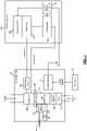
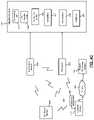
- FIG. 1is a block diagram of an example heating, ventilation, and air conditioning (HVAC) system
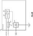
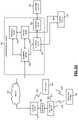
- FIG. 2Ais a functional block diagram of an air handler unit of an example HVAC system
- FIGS. 2B and 2Care functional block diagrams of example condenser units of example HVAC systems
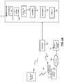
- FIG. 3is a functional block diagram of an example indoor air quality (IAQ) sensor module that can be used with an HVAC system and/or other mitigation devices;
- IAQindoor air quality
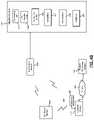
- FIGS. 4A-4Care a functional block diagram of an example IAQ control system
- FIG. 5Ais a functional block diagram of an example remote monitoring system
- FIG. 5Bis a functional block diagram of an example monitoring system
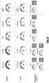
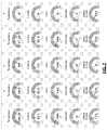
- FIGS. 6-9are example user interfaces displayed by a user computing device during execution of an application based on data received from a remote monitoring system
- FIG. 10includes a functional block diagram of an example implementation of an IAQ control module
- FIGS. 11-13include example graphs of an IAQ parameter (e.g., amount of particulate, amount of VOCs, or amount of carbon dioxide) over time;
- IAQ parametere.g., amount of particulate, amount of VOCs, or amount of carbon dioxide
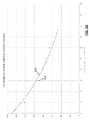
- FIGS. 14 and 15include example graphs of particulate matter (PM) over time
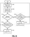
- FIG. 16includes a flowchart depicting an example method of controlling mitigation of an IAQ parameter
- FIG. 17includes a flowchart depicting an example method of indicating whether to replace a filter of an air handler unit
- FIG. 18includes a flowchart depicting an example method of classifying mitigation events
- FIG. 19includes an example graph of amount of particulate versus measured mitigation period
- FIG. 20includes an example graph of an amount of VOCs versus measured mitigation period
- FIG. 21includes a functional block diagram of an example implementation of a thermostat
- FIG. 22includes an example graph of particulate, volatile organic compounds (VOCs), and carbon dioxide (CO2) over time;
- VOCsvolatile organic compounds
- CO2carbon dioxide
- FIG. 23includes an example graph of particulate, VOCs, CO2, temperature, and relative humidity (RH) over time;
- FIG. 24includes a flowchart depicting an example method of mitigating IAQ parameters.
- an indoor air quality (IAQ) sensor modulecan be used with one or more mitigation devices of a residential or light commercial HVAC (heating, ventilation, and/or air conditioning) system of a building and/or one or more other mitigation devices.
- the IAQ sensor moduleincludes one, more than one, or all of a temperature sensor, a relative humidity (RH) sensor, a particulate sensor, a volatile organic compound (VOC) sensor, and a carbon dioxide (CO 2 ) sensor.
- the IAQ sensor modulemay also include one or more other IAQ sensors, such as occupancy, barometric pressure, light, sound, etc.
- the temperature sensorsenses a temperature of air at the location of the IAQ sensor.
- the RH sensormeasures a RH of air at the location of the IAQ sensor.
- the particulate sensormeasures an amount (e.g., concentration) of particulate greater than a predetermined size in the air at the location of the IAQ sensor.
- the VOC sensormeasures an amount of VOCs in the air at the location of the IAQ sensor.
- the carbon dioxide sensormeasures an amount of carbon dioxide in the air at the location of the IAQ sensor.
- Other IAQ sensorswould measure an amount of a substance or condition in the air at the location of the IAQ sensor.
- the IAQ sensor moduleis wirelessly connected to a thermostat of the HVAC system, such as via Bluetooth or WiFi.
- the IAQ sensor modulemay additionally or alternatively be wirelessly connected to a control module.
- the IAQ sensor modulecommunicates measurements from its sensors, and optionally, a time and date to the thermostat and/or the control module.
- the control module and/or the thermostatcan provide information on the measurements of the IAQ sensor module and other data (e.g., statuses of mitigation devices, local outdoor air conditions, etc.) to one or more user devices (e.g., of tenants, occupants, customers, contractors, etc.) associated with the building.
- the buildingmay be a single-family residence, and the customer may be the homeowner, a landlord, or a tenant.
- the buildingmay be a light commercial building, and the customer may be the building owner, a tenant, or a property management company.
- the control module and/or the thermostatcontrols operation of the mitigation devices based on the measurements from the IAQ sensor module.
- the control module and/or the thermostatcontrols operation of the mitigation devices based on maintaining a temperature measured by the IAQ sensor module within upper and lower temperature limits, based on maintaining a RH measured by the IAQ sensor within upper and lower RH limits, based on maintaining the amount of particulate in the air at the IAQ sensor module below a predetermined amount of particulate, based on maintaining the amount of VOCs in the air at the IAQ sensor module below a predetermined amount of VOCs, and/or based on maintaining the amount of carbon dioxide in the air at the IAQ sensor module below a predetermined amount of carbon dioxide.
- control module and/or the thermostatmay turn on a dehumidifier when the RH is greater than an upper dehumidification RH limit and maintain the dehumidifier on until the RH becomes less than a lower dehumidification RH limit.
- the control module and/or the thermostatmay turn on a humidifier when the RH is less than a lower humidification RH limit and maintain the humidifier on until the RH becomes greater than an upper humidification RH limit.
- the control module and/or the thermostatmay turn on a particulate decreasing device (e.g., an air cleaner/purifier) when the amount of particulate is greater than an upper particulate limit and maintain the particulate decreasing device on until the amount of particulate becomes less than a lower particulate limit.
- a particulate decreasing devicee.g., an air cleaner/purifier
- the control module and/or the thermostatmay turn on a carbon dioxide decreasing device (e.g., a ventilator) when the amount of carbon dioxide is greater than an upper carbon dioxide limit and maintain the carbon dioxide decreasing device on until the amount of carbon dioxide becomes less than a lower carbon dioxide limit.
- a carbon dioxide decreasing devicee.g., a ventilator
- a VOC decreasing devicee.g., a ventilator or an air/cleaner purifier
- the limitsmay be set to predetermined values by default. The limits, however, may be too high or too low for the building under some circumstances. The limits being too high or too low may cause over-use of one or more mitigation devices.
- the control modulemay therefore adjust (increase or decrease) one or more of the limits.
- mitigation of a deviation of one parametermay cause a deviation in another parameter and prompt mitigation of the other parameter.
- mitigation of VOCs and/or carbon dioxidemay cause an increase in RH within the building as air from within the building is vented to outside of the building and more humid outside air is drawn into the building. If the RH within the building increases to greater than the upper dehumidification RH limit due to the mitigation of VOCs and/or carbon dioxide, the control module and/or the thermostat may trigger dehumidification.
- the control modulemay adjust (increase or decrease) one or more of the limits. Adjusting one of more of the limits may increase an overall amount of time spent with one or more IAQ parameters between the respective upper and lower limits. Stated differently, one or more of the limits may decrease an overall amount of time spent with one or more IAQ parameters being mitigated or outside of the respective upper and lower limits.
- HVACcan encompass all environmental comfort systems in a building, including heating, cooling, humidifying, dehumidifying, and air exchanging and purifying, and covers devices such as furnaces, heat pumps, humidifiers, dehumidifiers, ventilators, and air conditioners. HVAC systems as described in this application do not necessarily include both heating and air conditioning, and may instead have only one or the other.
- an air handler unitIn split HVAC systems, an air handler unit is often located indoors, and a condensing unit is often located outdoors. In heat pump systems, the function of the air handler unit and the condensing unit are reversed depending on the mode of the heat pump. As a result, although the present disclosure uses the terms air handler unit and condensing unit, the terms indoor unit and outdoor unit could be used instead in the context of a heat pump. The terms indoor unit and outdoor unit emphasize that the physical locations of the components stay the same while their roles change depending on the mode of the heat pump. A reversing valve selectively reverses the flow of refrigerant from what is shown in FIG. 1 depending on whether the system is heating the building or cooling the building in a heat pump system.
- the control module and/or the thermostatupload data to a remote location.
- the remote locationmay be accessible via any suitable network, including the Internet.
- the remote locationincludes one or more computers, which will be referred to as servers.
- the serversexecute a monitoring system on behalf of a monitoring company. Additionally or alternatively, a user computing device may serve as the monitoring system.
- the monitoring systemreceives and processes the data from the controller and/or thermostat of customers who have such systems installed.
- the monitoring systemcan provide performance information, diagnostic alerts, and error messages to one or more users associated with the building and/or third parties, such as designated HVAC contractors.
- a server of the monitoring systemincludes a processor and memory.
- the memorystores application code that processes data received from the controller and/or the thermostat.
- the processorexecutes this application code and stores received data either in the memory or in other forms of storage, including magnetic storage, optical storage, flash memory storage, etc. While the term server is used in this application, the application is not limited to a single server.
- a collection of serversmay together operate to receive and process data from multiple buildings.
- a load balancing algorithmmay be used between the servers to distribute processing and storage.
- the present applicationis not limited to servers that are owned, maintained, and housed by a monitoring company. Although the present disclosure describes diagnostics and processing and alerting occurring in a remote monitoring system, some or all of these functions may be performed locally using installed equipment and/or customer resources, such as on a customer computer or computers.
- Customers and/or HVAC contractorsmay be notified of current and predicted issues (e.g., dirty filter) affecting effectiveness or efficiency of the HVAC system and/or the mitigating devices, and may receive notifications related to routine maintenance.
- the methods of notificationmay take the form of push or pull updates to an application, which may be executed on a smart phone, tablet, another type of mobile device, or on a computer (e.g., laptop or desktop).
- Notificationsmay also be viewed using web applications or on local displays, such as on the thermostat and/or other displays located throughout the building. Notifications may also include text messages, emails, social networking messages, voicemails, phone calls, etc.
- the monitoring companycan determine whether various components are operating at their peak performance.
- the monitoring companycan advise the customer and a contractor when performance is reduced. This performance reduction may be measured for the system as a whole, such as in terms of efficiency, and/or may be monitored for one or more individual components.
- the monitoring systemmay detect and/or predict failures of one or more components of the system.
- the customercan be notified and potential remediation steps can be taken immediately.
- components of the HVAC systemmay be shut down to prevent or minimize damage, such as water damage, to HVAC components.
- a contractorcan also be notified that a service call may be required.
- the contractormay schedule a service call to the building.
- the monitoring systemmay provide specific information to a contractor, such as identifying information of the customer's components, including make and model numbers, as well as indications of the specific part numbers of components. Based on this information, the contractor can allocate the correct repair personnel that have experience with the specific components and/or the system. In addition, a service technician is able to bring replacement parts, avoiding return trips after diagnosis.
- the customer and/or contractormay be advised of relevant factors in determining whether to repair or replace some or all of the components. For example only, these factors may include relative costs of repair versus replacement, and may include quantitative or qualitative information about advantages of replacement equipment. For example, expected increases in efficiency and/or comfort with new equipment may be provided. Based on historical usage data and/or electricity or other commodity prices, the comparison may also estimate annual savings resulting from the efficiency improvement.
- the monitoring systemmay also predict impending failures. This allows for preventative maintenance and repair prior to an actual failure of components. Alerts regarding detected or impending failures reduce the time when the HVAC system is out of operation and allows for more flexible scheduling for both the customer and contractor. If the customer is out of town, these alerts may prevent damage from occurring when the customer is not present to detect the failure of a component. For example, failure of heating components of the HVAC system in winter may lead to pipes freezing and bursting.
- Alerts regarding potential or impending failuresmay specify statistical timeframes before the failure is expected. For example only, if a sensor is intermittently providing bad data, the monitoring system may specify an expected amount of time before it is likely that the sensor effectively stops working due to the prevalence of bad data. Further, the monitoring system may explain, in quantitative or qualitative terms, how the current operation and/or the potential failure will affect operation of the HVAC system. This enables the customer to prioritize and budget for repairs.
- the monitoring companymay charge a periodic rate, such as a monthly rate. This charge may be billed directly to the customer and/or may be billed to the contractor. The contractor may pass along these charges to the customer and/or may make other arrangements, such as by requiring an up-front payment and/or applying surcharges to repairs and service visits.
- a periodic ratesuch as a monthly rate. This charge may be billed directly to the customer and/or may be billed to the contractor.
- the contractormay pass along these charges to the customer and/or may make other arrangements, such as by requiring an up-front payment and/or applying surcharges to repairs and service visits.
- the monitoring serviceallows the customer to remotely monitor real-time data within the building, outside of the building, and/or control components of the system, such as setting temperature and RH setpoints and other IAQ setpoints, enabling or disabling heating, cooling, ventilation, air purification, etc.
- the customermay be able to track usage data for components of the system and/or historical data.
- monitored datamay be transmitted to a local device in the building.
- a smartphone, laptop, or proprietary portable devicemay receive monitoring information to diagnose problems and receive real-time performance data.
- datamay be uploaded to the cloud and then downloaded onto a local computing device, such as via the Internet from an interactive web site.
- FIG. 1a block diagram of an example HVAC system is presented.
- a forced air system with a gas furnaceis shown.
- Return airis pulled from the building through a filter 104 by a circulator blower 108 .
- the circulator blower 108also referred to as a fan, is controlled by a control module 112 .
- the control module 112receives signals from a thermostat 116 .
- the thermostat 116may include one or more temperature set points specified by the user.
- the thermostat 116may direct that the circulator blower 108 be turned on at all times or only when a heat request or cool request is present (automatic fan mode).
- the circulator blower 108can operate at one or more discrete speeds or at any speed within a predetermined range.
- the control module 112may switch one or more switching relays (not shown) to control the circulator blower 108 and/or to select a speed of the circulator blower 108 .
- the thermostat 116provides the heat and/or cool requests to the control module 112 .
- the control module 112causes a burner 120 to ignite. Heat from combustion is introduced to the return air provided by the circulator blower 108 in a heat exchanger 124 .
- the heated airis supplied to the building and is referred to as supply air.
- the burner 120may include a pilot light, which is a small constant flame for igniting the primary flame in the burner 120 .
- a pilot lightwhich is a small constant flame for igniting the primary flame in the burner 120 .
- an intermittent pilotmay be used in which a small flame is first lit prior to igniting the primary flame in the burner 120 .
- a sparkermay be used for an intermittent pilot implementation or for direct burner ignition.
- Another ignition optionincludes a hot surface igniter, which heats a surface to a high enough temperature that, when gas is introduced, the heated surface initiates combustion of the gas.
- Fuel for combustionsuch as natural gas, may be provided by a gas valve 128 .
- the products of combustionare exhausted outside of the building, and an inducer blower 132 may be turned on prior to ignition of the burner 120 .
- the inducer blower 132creates a draft to exhaust the products of combustion.
- the inducer blower 132may remain running while the burner 120 is operating. In addition, the inducer blower 132 may continue running for a set period of time after the burner 120 turns off.
- a single enclosurewhich will be referred to as an air handler unit 136 , may include the filter 104 , the circulator blower 108 , the control module 112 , the burner 120 , the heat exchanger 124 , the inducer blower 132 , an expansion valve 140 , an evaporator 144 , and a condensate pan 146 .
- the air handler unit 136includes an electrical heating device (not shown) instead of or in addition to the burner 120 . When used in addition to the burner 120 , the electrical heating device may provide backup or secondary (extra) heat to the burner 120 .
- the HVAC systemincludes a split air conditioning system.
- Refrigerantis circulated through a compressor 148 , a condenser 152 , the expansion valve 140 , and the evaporator 144 .
- the evaporator 144is placed in series with the supply air so that when cooling is desired, the evaporator 144 removes heat from the supply air, thereby cooling the supply air.
- the evaporator 144is cold (e.g., below the dew point of the air within the building), which causes water vapor to condense. This water vapor is collected in the condensate pan 146 , which drains or is pumped out.
- a control module 156receives a cool request from the control module 112 and controls the compressor 148 accordingly.
- the control module 156also controls a condenser fan 160 , which increases heat exchange between the condenser 152 and outside air.
- the compressor 148 , the condenser 152 , the control module 156 , and the condenser fan 160are generally located outside of the building, often in a single condensing unit 164 .
- control module 156may include a run capacitor, a start capacitor, and a contactor or relay.
- start capacitormay be omitted, such as when the condensing unit 164 includes a scroll compressor instead of a reciprocating compressor.
- the compressor 148may be a variable-capacity compressor and may respond to a multiple-level cool request.
- the cool requestmay indicate a mid-capacity call for cooling or a high-capacity call for cooling.
- the compressor 148may vary its capacity according to the cool request.
- the electrical lines provided to the condensing unit 164may include a 240 volt mains power line (not shown) and a 24 volt switched control line.
- the 24 volt control linemay correspond to the cool request shown in FIG. 1 .
- the 24 volt control linecontrols operation of the contactor.
- the contactorWhen the control line indicates that the compressor should be on, the contactor contacts close, connecting the 240 volt power supply to the compressor 148 .
- the contactormay connect the 240 volt power supply to the condenser fan 160 .
- the condenser fan 160may be omitted.
- the contactormay have two sets of contacts, and can be referred to as a double-pole single-throw switch.
- the thermostat 116includes a temperature sensor and a relative humidity (RH) sensor.
- a heating (heat) modethe thermostat 116 generates a heat request when the temperature measured by the temperature sensor is less than a lower temperature limit.
- a cooling (cool) modethe thermostat 116 generates a cool request when the temperature measured by the temperature sensor is greater than an upper temperature limit.
- the upper and lower temperature limitsmay be set to a setpoint temperature+ and ⁇ a predetermined amount (e.g., 1, 2, 3, 4, 5 degrees Fahrenheit), respectively.
- the setpoint temperaturemay be set to a predetermined temperature by default and may be adjusted by a user.
- FIGS. 2A-2Bare functional block diagrams of an example monitoring system associated with an HVAC system of a building.
- the air handler unit 136 of FIG. 1is shown for reference.
- the thermostat 116 of FIG. 1is a WiFi thermostat 208 having networking capability.
- the air handler unit 136is located inside the building, while the condensing unit 164 is located outside the building.
- the present disclosureis not limited to that arrangement, however, and applies to other systems including, as examples only, systems where the components of the air handler unit 136 and the condensing unit 164 are located in close proximity to each other or even in a single enclosure.
- the single enclosuremay be located inside or outside of the building.
- the air handler unit 136may be located in a basement, garage, or attic.
- the air handler unit 136 and the condensing unit 164may be located near the earth, such as in a basement, crawlspace, garage, or on the first floor, such as when the first floor is separated from the earth by only a concrete slab.
- a transformer 212can be connected to an AC line in order to provide AC power to the control module 112 and the thermostat 208 .
- the transformer 212may be a 10-to-1 transformer and therefore provide either a 12V or 24V AC supply depending on whether the air handler unit 136 is operating on nominal 120 volt or nominal 240 volt power.
- the control module 112controls operation in response to signals from the thermostat 208 received over control lines.
- the control linesmay include a call for cool (cool request), a call for heat (heat request), and a call for fan (fan request).
- the control linesmay include a line corresponding to a state of a reversing valve in heat pump systems.
- the control linesmay further carry calls for secondary heat and/or secondary cooling, which may be activated when the primary heating or primary cooling is insufficient.
- secondary heat and/or secondary coolingwhich may be activated when the primary heating or primary cooling is insufficient.
- control signals related to the selection of the fuelmay be monitored.
- additional status and error signalsmay be monitored, such as a defrost status signal, which may be asserted when the compressor is shut off and a defrost heater operates to melt frost from an evaporator.
- the condensing unit 164may include an ambient temperature sensor that generates temperature data.
- the ambient temperaturerepresents an outside (or outdoor) ambient temperature.
- the temperature sensor supplying the ambient temperaturemay be located outside of an enclosure of the condensing unit 164 .
- the temperature sensormay be located within the enclosure, but exposed to circulating air.
- the temperature sensormay be shielded from direct sunlight and may be exposed to an air cavity that is not directly heated by sunlight.
- online (including Internet-based) weather databased on the geographical location of the building may be used to determine sun load, outside ambient air temperature, relative humidity, particulate, VOCs, carbon dioxide, etc.
- an example condensing unit 268is shown for a heat pump implementation.
- the condensing unit 268may be configured similarly to the condensing unit 164 of FIG. 2B .
- the mode of the heat pumpdetermines whether the condenser 152 of the condensing unit 268 is actually operating as a condenser or as an evaporator.
- a reversing valve 272is controlled by a control module 276 and determines whether the compressor 148 discharges compressed refrigerant toward the condenser 152 (cooling mode) or away from the condenser 152 (heating mode).
- the control module 276controls the reversing valve 272 and the compressor 148 based on the control signals.
- the control module 276may receive power, for example, from the transformer 212 of the air handler unit 136 or via the incoming AC power line.
- FIG. 3includes a functional block diagram of an example indoor air quality (IAQ) sensor module 304 that can be used with an HVAC system and/or one or more other mitigation devices.
- the IAQ sensor module 304includes one, more than one, or all of: a temperature sensor 308 , a relative humidity (RH) sensor 312 , a particulate sensor 316 , a volatile organic compounds (VOC) sensor 320 , and a carbon dioxide sensor 324 .
- the IAQ sensor module 304may also include a sampling module 328 and a transceiver module 332 .
- a power supply 336may receive AC power from a standard wall outlet (or receptacle) 340 via a plug 344 .
- the standard wall outlet 340may provide nominal 120 volt or nominal 240 volt AC power.
- the power supply 336may include an AC to direct current (DC) converter that converts the AC power into DC power, such as 5 volt, 12 volt, or 24 volt DC power.
- the power supply 336supplies power to the components of the IAQ sensor module 304 including the sensors, the sampling module 328 , and the transceiver module 332 . While the example of the power supply 336 being integrated within the IAQ sensor module 304 is provided, the power supply 336 may be integrated with the plug 344 in various implementations. Also, while the example of the power supply 336 providing one DC voltage to the components of the IAQ sensor module 304 , the power supply 336 may provide two or more different DC voltages to different components of the IAQ sensor module 304 .
- the power supply 336may include one or more batteries or one or more solar cells that supply power to the components of the IAQ sensor module 304 .
- the one or more batteriesmay be replaceable or non-replaceable.
- the one or more batteriesmay be re-chargeable, such as via a standard wall outlet.
- the IAQ sensor module 304may include a charger that charges the one or more batteries using power supplied, for example, via a standard wall outlet.
- the IAQ sensor module 304is portable and can be moved into different rooms of a building.
- the IAQ sensor module 304could also be placed outside the building, for example, to measure one or more conditions outside of the building, calibration, or for one or more other reasons.
- the temperature sensor 308measures a temperature of air at the IAQ sensor module 304 .
- the RH sensor 312measures a relative humidity of air at the IAQ sensor module 304 .
- the particulate sensor 316measures an amount (e.g., a mass flow rate, such as micrograms ( ⁇ g) per cubic meter) of particulate in air at the IAQ sensor module 304 having a diameter that is less than a predetermined size (e.g., 2.5 or 10 micrometers ( ⁇ m)).
- the VOC sensor 320measures an amount (e.g., parts per billion (ppb)) of VOC in air at the IAQ sensor module 304 .
- the carbon dioxide sensor 324measures an amount (e.g., ppm) of carbon dioxide in air at the IAQ sensor module 304 .
- the included ones of the temperature sensor 308 , the RH sensor 312 , the particulate sensor 316 , the VOC sensor 320 , and the carbon dioxide sensor 324will be referred to collectively as the IAQ sensors.
- the sampling module 328samples (analog) measurements of the IAQ sensors.
- the sampling module 328may also digitize and/or store values of the measurements of the IAQ sensors.
- the IAQ sensorsmay be digital sensors and output digital values corresponding to the respective measured parameters.
- the sampling module 328may perform storage or may be omitted.
- the IAQ sensor module 304may include one or more expansion ports to allow for connection of additional sensors and/or to allow connection to other devices.
- Examples of other devicesinclude one or more other IAQ sensor modules, one or more other types of the IAQ sensors not included in the IAQ sensor module 304 , a home security system, a proprietary handheld device for use by contractors, a mobile computing device, and other types of devices.
- the transceiver module 332transmits frames of data corresponding to predetermined periods of time.
- Each frame of datamay include the measurements of the IAQ sensors over a predetermined period.
- One or more calculationsmay be performed for the data of each frame of data, such as averaging the measurements of one or more of the IAQ sensors.
- Each frame(including the calculations and/or the measurements) may be transmitted to a monitoring system, as discussed further below.
- the measurements of the IAQ sensorsmay be sampled at a predetermined rate, such as 10 samples per minute or another suitable rate.
- Each framemay correspond to a predetermined number of sets of samples (e.g., 10 ).
- the monitoring systemmay provide visual representations of the measurements over predetermined periods of time along with other data, as discussed further below.
- the transceiver module 332transmits each frame (including the calculations and/or the measurements) to an IAQ control module 404 and/or the thermostat 208 .
- the transceiver module 332transmits the frames wirelessly via one or more antennas, such as antenna 348 , using a proprietary or standardized, wired or wireless protocol, such as Bluetooth, ZigBee (IEEE 802.15.4), 900 Megahertz, 2.4 Gigahertz, WiFi (IEEE 802.11).
- the IAQ sensor module 304may communicate directly with the IAQ control module 404 and/or the thermostat 208 or with a separate computing device, such as a smartphone, tablet, or another type of computing device.
- a gateway 408is implemented, which creates a wireless network for the IAQ sensor module 304 , the IAQ control module 404 , and the thermostat 208 .
- the gateway 408may also interface with a customer router 412 using a wired or wireless protocol, such as Ethernet (IEEE 802.3).
- the IAQ control module 404may communicate with the customer router 412 using WiFi. Alternatively, the IAQ control module 404 may communicate with the customer router 412 via the gateway 408 .
- the thermostat 208may also communicate with the customer router 412 using WiFi or via the gateway 408 . In various implementations, the IAQ control module 404 and the thermostat 208 may communicate directly or via the gateway 408 .
- the IAQ sensor module 304 , the IAQ control module 404 , and/or the thermostat 208transmits data measured by the IAQ sensor module 304 and parameters of the IAQ control module 404 and/or the thermostat 208 over a wide area network 416 , such as the Internet (referred to as the Internet 416 ).
- the IAQ sensor module 304 , the IAQ control module 404 , and/or the thermostat 208may access the Internet 416 using the customer router 412 of the customer.
- the customer router 412may already be present to provide Internet access to other devices (not shown) within the building, such as a customer computer and/or various other devices having Internet connectivity, such as a DVR (digital video recorder) or a video gaming system.
- DVRdigital video recorder
- the IAQ sensor module 304 , the IAQ control module 404 , and/or the thermostat 208transmit the data to a remote monitoring system 420 via the Internet 416 using the customer router 412 . Further discussion of the remote monitoring system 420 is provided below.
- the IAQ control module 404 and/or the thermostat 208control operation (e.g., on, off, speed, etc.) of mitigation devices 424 based on the measurements from the IAQ sensor module 304 .
- the measurements of the IAQ sensor module 304may be provided to the thermostat 208 and the thermostat 208 may control operation of the mitigation devices 424 in various implementations (e.g., FIG. 4A ).
- the IAQ control module 404can be omitted in such implementations. While the example of the thermostat 208 controlling the mitigation devices 424 will be discussed, alternatively the IAQ control module 404 may control operation of the mitigation devices 424 (e.g., FIG. 4B ), or the thermostat 208 and the IAQ control module 404 may together control the mitigation devices 424 (e.g., FIG. 4C ).
- the IAQ control module 404 and/or thermostat 208control and communicate with the mitigation devices 424 wirelessly, by wire, using a combination of wireless and wired connections.
- the IAQ control module 404 , the thermostat 208 , and the mitigation devices 424include respective transceivers.
- the mitigation devices 424include: (i) the condensing unit 164 , (ii) the air handler unit 136 (e.g., the circulator blower 108 ), (iii) an air cleaner/purifier 428 , (iv) a humidifier 432 , (v) a dehumidifier 436 , and (vi) a ventilator 440 .
- the air cleaner/purifier 428may be separate from the air handler unit 136 (e.g., a standalone air cleaner/purifier). In various implementations, the air handler unit 136 may serve as the air cleaner/purifier 428 .
- the air cleaner/purifier 428draws in air and forces the air through a filter before expelling filtered air to the building.
- the filtermay be rated (e.g., minimum efficiency reporting value, MERV) to remove a predetermined amount (e.g., 95%) of particulate of the size measured by the particulate sensor 316 .
- Operation of the air cleaner/purifier 428may include whether the air cleaner/purifier 428 is on or off and, when on, a speed of the air cleaner/purifier 428 .
- the air cleaner/purifier 428may have a single speed or multiple discrete speeds.
- Operation of the air cleaner/purifier 428may be controlled via wire or wirelessly by the thermostat 208 .
- wireless communication and controlinclude, but are not limited to, Bluetooth connections and WiFi connections.
- the thermostat 208may wirelessly control whether the air cleaner/purifier 428 is on or off and, if on, the speed of the air cleaner/purifier 428 .
- the thermostat 208may turn the air cleaner/purifier 428 on when the amount of particulate measured by the particulate sensor 316 is greater than a first predetermined amount of particulate.
- the thermostat 208may leave the air cleaner/purifier 428 on until the amount of particulate measured by the particulate sensor 316 is less than a second predetermined amount of particulate that is less than the first predetermined amount of particulate.
- the thermostat 208may turn the air cleaner/purifier 428 off when the amount of particulate measured by the particulate sensor 316 is less than the second predetermined amount of particulate.
- the thermostat 208may vary the speed of the air cleaner/purifier 428 based on the amount of particulate measured by the particulate sensor 316 . For example, the thermostat 208 may increase the speed of the air cleaner/purifier 428 as the amount of particulate increases and vice versa.
- the humidifier 432humidifies air within the building.
- the humidifier 432may be included with the air handler unit 136 or a standalone humidifier.
- the humidifier 432may add moisture to the supply air before the supply air is output from vents to the building.
- the humidifier 432may add moisture to air, for example, by supplying water to a medium (e.g., a pad) and forcing air (e.g., supply air) through the hydrated medium.
- the humidifier 432may spray water in the form of mist into air (e.g., supply air).
- the humidifier 432may spray water in the form of mist into air.
- Operation of the humidifier 432may include whether the humidifier 432 is on or off. In various implementations, operation of the humidifier 432 may also include a humidification rate (e.g., an amount of water supplied to the pad or into the air as mist). The humidifier 432 may be configured to provide only a single humidification rate or multiple different humidification rates.
- a humidification ratee.g., an amount of water supplied to the pad or into the air as mist.
- the humidifier 432may be configured to provide only a single humidification rate or multiple different humidification rates.
- Operation of the humidifier 432may be controlled via wire or wirelessly by the thermostat 208 .
- the thermostat 208may control (by wire) whether the humidifier 432 included with the air handler unit 136 is on or off.
- the thermostat 208may wirelessly control whether the humidifier 432 is on or off and a humidification rate when on. Examples of wireless communication include, but are not limited to, Bluetooth connections and WiFi connections.
- the thermostat 208may turn the humidifier 432 on when the RH measured by the RH sensor 312 is less than a first predetermined RH.
- the thermostat 208may leave the humidifier 432 on until the RH measured by the RH sensor 312 is greater than a second predetermined RH that is greater than the first predetermined RH.
- the thermostat 208may turn the humidifier 432 off when the RH measured by the RH sensor 312 is greater than the second predetermined RH.
- the dehumidifier 436dehumidifies (i.e., removes humidity from) air within the building.
- the dehumidifier 436may be included with the air handler unit 136 or a standalone dehumidifier.
- the dehumidifier 436may draw moisture from the supply air (or add dry air to the supply air) before the supply air is output from vents to the building. Operation of the dehumidifier 436 may include whether the dehumidifier 436 is on or off.
- Operation of the dehumidifier 436may be controlled via wire or wirelessly by the thermostat 208 .
- the thermostat 208may control (by wire) whether the dehumidifier 436 included with the air handler unit 136 is on or off.
- the thermostat 208may wirelessly control whether the dehumidifier 436 , implemented as a standalone device, is on or off.
- the thermostat 208may turn the dehumidifier 436 on when the RH measured by the RH sensor 312 is greater than a third predetermined RH.
- the third predetermined RHmay be the same as the second predetermined RH or different than (e.g., greater than) the second predetermined RH.
- the thermostat 208may leave the dehumidifier 436 on until the RH measured by the RH sensor 312 is less than a fourth predetermined RH that is less than the third predetermined RH.
- the thermostat 208may turn the dehumidifier 436 off when the RH measured by the RH sensor 312 is less than the fourth predetermined RH.
- the fourth predetermined RHmay be the same as the first predetermined RH or different than (e.g., greater than) the first predetermined RH.
- the ventilator 440vents air from within the building out of the building. This also passively draws air from outside of the building into the building.
- the ventilator 440may be included with the air handler unit 136 (e.g., the inducer blower 132 ) or a standalone ventilator. Examples of standalone ventilators include blowers that blow air from within the building out of the building (e.g., range hoods fans, bathroom fans, the inducer blower, etc.). Operation of the ventilator 440 may include whether the ventilator 440 is on or off and, when on, a speed.
- the ventilator 440may be configured to operate at a single speed or multiple different speeds.
- Operation of the ventilator 440may be controlled via wire or wirelessly by the thermostat 208 .
- the thermostat 208may wirelessly control whether the ventilator 440 is on or off and, if on, the speed of the ventilator 440 .
- the thermostat 208may turn the ventilator 440 on when the amount of VOCs measured by the VOC sensor 320 is greater than a first predetermined amount of VOCs.
- the thermostat 208may leave the ventilator 440 on until the amount of VOCs measured by the VOC sensor 320 is less than a second predetermined amount of VOCs that is less than the first predetermined amount of VOCs.
- the thermostat 208may turn the ventilator 440 off when the amount of VOCs measured by the VOC sensor 320 is less than the second predetermined amount of VOCs.
- the thermostat 208may turn the ventilator 440 on when the amount of carbon dioxide measured by the carbon dioxide sensor 324 is greater than a first predetermined amount of carbon dioxide.
- the thermostat 208may leave the ventilator 440 on until the amount of carbon dioxide measured by the carbon dioxide sensor 324 is less than a second predetermined amount of carbon dioxide that is less than the first predetermined amount of carbon dioxide.
- the thermostat 208may turn the ventilator 440 off when the amount of carbon dioxide measured by the carbon dioxide sensor 324 is less than the second predetermined amount of carbon dioxide.
- mitigation devices described aboveare only described as example. One or more of the example mitigation devices may be omitted. One or more other types of mitigation devices may be included. Additionally, while the example of only one of each type of mitigation device is provided, two or more of a given type of mitigation device may be included and controlled.
- Changes in temperature and/or humidityalso cause changes in particulate, VOCs, and/or carbon dioxide.
- a change in temperaturemay cause a change in VOCs, RH, particulate, and/or carbon dioxide.
- a change in RHmay cause a change in particulate, VOCs, and/or carbon dioxide.
- particulatemay increase as RH increases and vice versa.
- the thermostat 208therefore controls operation of the mitigation devices 424 based on all of the parameters measured by the IAQ sensor module 304 in an attempt to: adjust the temperature within a predetermined temperature range, adjust the RH within a predetermined RH range, adjust the amount of particulate (if measured) to less than a predetermined amount of particulate, adjust the amount of VOCs (if measured) to less than a predetermined amount of VOCs, and to adjust the amount of carbon dioxide (if measured) to less than a predetermined amount of carbon dioxide.
- FIG. 5Aincludes a functional block diagram of an example monitoring system.
- the IAQ control module 404 and/or the thermostat 208are shown transmitting, using the customer router 412 , data to the remote monitoring system 420 via the Internet 416 .
- the IAQ control module 404 and/or the thermostat 208may transmit the data to an external wireless receiver.
- the external wireless receivermay be a proprietary receiver for a neighborhood in which the building is located, or may be an infrastructure receiver, such as a metropolitan area network (such as WiMAX), a WiFi access point, or a mobile phone base station.
- the remote monitoring system 420includes a monitoring server 508 that receives data from the IAQ control module 404 and/or the thermostat 208 and maintains and verifies network continuity with the IAQ control module 404 and/or the thermostat 208 .
- the monitoring server 508executes various algorithms to store setpoints for the building and to store measurements from the thermostat 208 and/or the IAQ sensor module 304 taken over time.
- the monitoring server 508may notify a review server 512 when one or more predetermined conditions are satisfied.
- This programmatic assessmentmay be referred to as an advisory.
- Some or all advisoriesmay be triaged by a technician to reduce false positives and potentially supplement or modify data corresponding to the advisory.
- a technician device 516 operated by a technicianmay be used to review the advisory and to monitor data (in various implementations, in real-time) from the IAQ control module 404 and/or the thermostat 208 via the monitoring server 508 .
- a technician using the technician device 516may review the advisory. If the technician determines that a problem or fault is either already present or impending, the technician instructs the review server 512 to send an alert to a customer device 524 that is associated with the building. The technician may determine that, although a problem or fault is present, the cause is more likely to be something different than specified by the automated advisory. The technician can therefore issue a different alert or modify the advisory before issuing an alert based on the advisory. The technician may also annotate the alert sent to the customer device 524 with additional information that may be helpful in identifying the urgency of addressing the alert and presenting data that may be useful for diagnosis or troubleshooting.
- minor problemsmay not be reported to the customer device 524 so as not to alarm the customer or inundate the customer with alerts.
- the review server 512(or a technician) may determine whether a problem is minor based on a threshold. For example, an efficiency decrease greater than a predetermined threshold may be reported to the customer device 524 , while an efficiency decrease less than the predetermined threshold may not be reported to the customer device 524 .
- the technician device 516may be remote from the remote monitoring system 420 but connected via a wide area network.
- the technician device 516may include a computing device such as a laptop, desktop, smartphone, or tablet.
- the customercan access a customer portal 528 , which provides historical and real-time data from the IAQ control module 404 and/or the thermostat 208 .
- the customer portal 528may also provide setpoints and predetermined ranges for each of the measurements, local outdoor air quality data, statuses of the mitigation devices 424 (e.g., on or off), and other data to the customer device 524 .
- the customerVia the customer device 524 , the customer may change the setpoints and predetermined ranges.
- the monitoring server 508transmits changed setpoints and predetermined ranges to the thermostat 208 and/or the IAQ control module 404 for use in controlling operation of the mitigation devices 424 .
- the remote monitoring system 420includes a local data server 520 that obtains local data at (outside) the building.
- the local data server 520may obtain the local data from one or more local data sources 532 via a wide area network, such as the internet 416 , using a geographical location of the building.
- the geographical locationmay be, for example, an address, zip code, coordinates, or other geographical identifier of the building.
- the remote monitoring system 420may obtain the geographical location of the building, for example, via the customer device 524 before providing data to the customer device 524 .
- the local dataincludes, for example, air temperature within a predetermined geographical area including the geographical location of the building, RH within the predetermined geographical area, amount of VOCs in the air within the predetermined geographical area, amount of particulate of the predetermined size measured by the particulate sensor 316 within the predetermined geographical area, and amount of carbon dioxide within the predetermined geographical area.
- FIG. 5Bincludes a functional block diagram of an example monitoring system where the customer device 524 serves as a monitoring system and provides the functionality of the remote monitoring system 420 .
- the thermostat 208 and/or the IAQ control module 404transmit data to the customer device 524 wirelessly, such as via a Bluetooth connection, WiFi, or another wireless connection.
- the customer device 524may obtain the local data from the local data sources 532 via a wide area network, such as the internet 416 .
- the IAQ control module 404 or the thermostat 208may serve as a monitoring system and provide the functionality of the remote monitoring system 420 .
- FIG. 6includes an example user interface displayed by the customer device 524 during execution of the application based on data from the customer portal 528 . It should be understood that the following functions are performed by the customer device 524 during execution of the application.
- the customer device 524may display real-time values of the temperature, RH, amount of VOCs, amount of particulate, and amount of carbon dioxide (CO2) measured by the IAQ sensor module 304 .
- theseare illustrated in the row labeled “indoor” as they represent parameters within the building.
- the real-time valuesmay be received by the customer device 524 from the monitoring server 508 via the customer portal 528 .
- the customer device 524may also display real-time values of the temperature, RH, amount of VOCs, amount of particulate, and amount of carbon dioxide (CO2) measured outside of the building but within the predetermined geographical area including the geographical area of the building. In FIG. 6 , these are illustrated in the row labeled “outdoor” as they represent parameters outside of the building.
- the real-time valuesmay be received by the customer device 524 from the monitoring server 508 via the customer portal 528 .
- the customer device 524may also display present setpoints for beginning heating (Heat) of the building, cooling (Cool) of the building, humidification (Humidify), dehumidification (Dehumidify), VOC removal (VOCs), particulate removal (Particulate), and carbon dioxide removal (Carbon Dioxide).
- these setpointsare illustrated in the row labeled “setpoints” as they represent setpoints for beginning associated mitigation actions within the building.
- the present setpointsmay be received by the customer device 524 from the monitoring server 508 via the customer portal 528 .
- a predetermined range for a measurementmay be set based on the setpoint for a measurement. For example, a predetermined range for heating may be set to the temperature setpoint for heating plus and minus a predetermined amount. A predetermined range for cooling may be set to the temperature setpoint for cooling plus and minus a predetermined amount. The predetermined amount may be user adjustable in various implementations.
- the customer device 524also allows a user to adjust one or more of the present setpoints via the customer device 524 .
- the customer device 524may provide positive and negative adjustment inputs in association with one, more than one, or all of the setpoints to allow for adjustment of the present setpoints.
- FIG. 6includes the example of +serving as the positive adjustment input and—serving as the negative adjustment input. Adjustment inputs labeled and provided differently, however, may be used.
- the customer device 524may transmit a command to the monitoring server 508 to adjust (i.e., increment or decrement) the setpoint by a predetermined amount. For example, in response to receipt of input indicative of user interaction (e.g., touching, clicking, etc.) with the positive adjustment input associated with the heating temperature setpoint, the customer device 524 may transmit a command to the monitoring server 508 to increment the heating temperature setpoint by a first predetermined amount.
- the customer device 524may transmit a command to the monitoring server 508 to decrement the heating temperature setpoint by the first predetermined amount.
- the customer device 524may transmit a command to the monitoring server 508 to increment the humidification RH setpoint by a second predetermined amount.
- the customer device 524may transmit a command to the monitoring server 508 to decrement the humidification RH setpoint by the second predetermined amount.
- the monitoring server 508relays (transmits) received commands for adjusting setpoints to the thermostat 208 and/or the IAQ control module 404 via the internet 416 .
- the customer device 524may transmit commands for adjusting setpoints to the thermostat 208 and/or the IAQ control module 404 directly or via the internet 416 .
- the thermostat 208 and/or the IAQ control module 404adjust the associated setpoints in response to the commands received from the monitoring server 508 .
- FIG. 7includes an example user interface displayed by the customer device 524 during execution of the application when the building includes multiple IAQ sensor modules. In the example of FIG. 7 , the measurements from each IAQ sensor module are shown in a separate column.
- one or more of the IAQ sensorsmay be omitted from an IAQ sensor module.
- the associated IAQ sensor moduleonly includes a particulate sensor and a carbon dioxide sensor.
- the temperature, relative humidity, and VOCs of zero in the example of FIG. 7indicate that the IAQ sensor module does not include a temperature sensor, a humidity sensor, or a VOC sensor.
- FIG. 8includes an example user interface displayed by the customer device 524 during execution of the application based on additional data indicative of present statuses of control modes and present (operation) statuses of various devices and modes of devices of the building.
- the present statusesmay be, for example, on or off.
- the present status of a control mode, device, or mode of a devicemay be on (currently in use) or off (not currently in use).
- One type of indicatormay be used to indicate a present status of on, while another type of indicator may be used to indicate a present status of off.
- the customer device 524may display the additional data concurrently with the data from one or more IAQ modules, the local data, and/or the setpoint data.
- the customer device 524selectively displays measurements of one or more IAQ sensor modules, local data, control modes, and/or statuses from a predetermined period of time.
- the predetermined period of timemay be, for example, the present day, a predetermined number of days (including or not including the present day), a predetermined number of hours before a present time, a predetermined number of minutes before the present time, or another suitable period.
- a predetermined periodmay be selected (e.g., the present day), but a user may select a different predetermined period and the customer device 524 may display the data for the selected predetermined period.
- FIG. 9includes an example user interface displayed by the customer device 524 during execution of the application for the present day (from 12:01 pm of the present day to the present time (approximately 10 pm in this example)).
- the customer device 524displays data selected by a user of the customer device 524 . By default, all data may be selected, but a user may select less than all of the data to be displayed, and the customer device 524 may display only the selected data.
- the customer device 524selectively displays a user interface for user selection of a priority for mitigating deviations in IAQ parameters (temperature, RH, particulate, VOCs, carbon dioxide).
- the customer device 524may display a user interface that allows user assignment of an order of prioritization for: (i) temperature control: (ii) RH control; (iii) particulate control; (vi) VOC control; and (v) carbon dioxide control.
- Temperature controlmay refer to maintaining, as much as possible, the temperature within the building within a predetermined temperature range.
- RH controlmay refer to maintaining, as much as possible, the RH within the building within a predetermined temperature range.
- Particulate controlmay refer to maintaining, as much as possible, the amount of particulate within the building less than a predetermined amount of particulate.
- VOC controlmay refer to maintaining, as much as possible, the amount of VOCs within the building less than a predetermined amount of VOCs.
- Carbon dioxide controlmay refer to maintaining, as much as possible, the amount of carbon dioxide within the building less than a predetermined amount of carbon dioxide.
- the order of prioritization for (i)-(v)may be initially preset, but may be user selected, as stated above.
- the thermostat 208 and/or the IAQ control module 404may control the mitigation devices 424 based on the prioritization (order). For example, when particulate control is the first priority, the thermostat 208 may control the mitigation devices 424 to decrease particulate as quickly as possible as opposed to, for example, controlling the mitigation devices 424 to more quickly adjust temperature or RH or to more quickly decrease the amount of VOCs and/or the amount of carbon dioxide.
- the user interfaces provided by the customer device 524provide visual information to the user regarding real-time measurements, historical measurements over a period of time, trends, and efficacy of IAQ mitigation and control.
- the user interfacesalso enable the user to adjust setpoints to be used to control the mitigation devices 424 to control comfort and IAQ within the building.
- the user interfacesalso enable the user to adjust prioritization in which IAQ conditions are mitigated. All of the above improves IAQ within the building and user experience regarding IAQ within the building.
- FIG. 10includes a block diagram of an example implementation of a mitigation system using the example of the IAQ control module 404 . While the example of the IAQ control module 404 is provided for purposes of discussion, the modules of the IAQ control module 404 may alternatively be implemented within the thermostat 208 or within a combination of the thermostat 208 and the IAQ control module 404 .
- a mitigation module 1004selectively turns on and off ones of the mitigation devices 424 based on the associated ones of the IAQ parameters and respective thresholds.
- a thresholds module 1008sets the thresholds, as discussed further below.
- the mitigation module 1004may turn one or more filtering devices (e.g., the air cleaner/purifier 428 and/or the circulator blower 108 ) on when the amount of particulate measured by the particulate sensor 316 is greater than a first ON threshold amount of particulate and a second ON threshold amount of particulate, such as described in FIGS. 11 to 13 .
- the mitigation module 1004may leave the one or more filtering devices on until the amount of particulate measured by the particulate sensor 316 becomes less than an OFF threshold amount of particulate and one or more OFF conditions are satisfied.
- the mitigation module 1004may turn the one or more filtering devices off when the amount of particulate measured by the particulate sensor 316 is less than the OFF threshold amount of particulate and one or more OFF conditions are satisfied.
- the mitigation module 1004may turn the ventilator 440 on when the amount of VOCs measured by the VOC sensor 320 is greater than a first ON VOC threshold and a second ON VOC threshold. The mitigation module 1004 may leave the ventilator 440 on until the amount of VOCs measured by the VOC sensor 320 is less than an OFF VOC threshold and one or more OFF conditions are satisfied. The mitigation module 1004 may turn the ventilator 440 off when the amount of VOCs measured by the VOC sensor 320 is less than the OFF VOC threshold and one or more OFF conditions are satisfied.
- the mitigation module 1004may turn the ventilator 440 on when the amount of carbon dioxide measured by the carbon dioxide sensor 324 is greater than a first ON carbon dioxide threshold and a second ON carbon dioxide threshold. The mitigation module 1004 may leave the ventilator 440 on until the amount of carbon dioxide measured by the carbon dioxide sensor 324 is less than an OFF carbon dioxide threshold. The mitigation module 1004 may turn the ventilator 440 off when the amount of carbon dioxide measured by the carbon dioxide sensor 324 is less than the OFF carbon dioxide threshold.
- the thresholds module 1008sets the first ON threshold amount of particulate, the second ON threshold amount of particulate, and the OFF threshold amount of particulate.
- the thresholds module 1008also sets the first ON VOC threshold, the second ON VOC threshold, and the OFF VOC threshold.
- the thresholds module 1008also sets the first ON carbon dioxide threshold, the second ON carbon dioxide threshold, and the OFF carbon dioxide threshold.
- the thresholds module 1008sets the first ON threshold amount of particulate based on a clean amount of particulate in the air and an ON predetermined amount of particulate. For example, the thresholds module 1008 may set the first ON threshold amount of particulate to the clean amount of particulate plus the ON predetermined amount of particulate.
- the ON predetermined amount of particulatemay be a fixed predetermined value or may be a variable, such as a percentage (less than 100 percent) or a fraction (less than 1) of the clean amount of particulate. This may ensure that there is no nuisance due to sensor response error variability.
- the thresholds module 1008sets the second ON threshold amount of particulate to a fixed predetermined amount of particulate.
- the fixed predetermined amount of particulatemay be greater than, less than, or equal to the clean amount of particulate.
- the thresholds module 1008sets the OFF threshold amount of particulate based on (a) an OFF predetermined amount of particulate and (b) the greater one of the first ON threshold amount of particulate and the second ON threshold amount of particulate. For example, the thresholds module 1008 may set the OFF threshold amount of particulate to (a) the OFF predetermined amount of particulate plus (b) the greater one of the first ON threshold amount of particulate and the second ON threshold amount of particulate.
- the OFF predetermined amount of particulatemay be a fixed predetermined value or may be a variable, such as a percentage (less than 100 percent) or a fraction (less than 1) of the clean amount of particulate. The OFF threshold amount of particulate will therefore be greater than both of the first and second ON threshold amounts of particulate.
- the thresholds module 1008sets the first ON VOC threshold based on a clean amount of VOCs in the air and an ON predetermined amount of VOCs. For example, the thresholds module 1008 may set the first ON VOC threshold to the clean amount of VOCs plus the ON predetermined amount of VOCs.
- the ON predetermined amount of VOCsmay be a fixed predetermined value or may be a variable, such as a percentage (less than 100 percent) or a fraction (less than 1) of the clean amount of VOCs.
- the thresholds module 1008sets the second ON VOC threshold amount of particulate to a fixed predetermined amount of VOCs.
- the fixed predetermined amount of VOCsmay be greater than, less than, or equal to the clean amount of VOCs.
- the thresholds module 1008sets the OFF VOC threshold based on (a) an OFF predetermined amount of VOCs and (b) the greater one of the first ON VOC threshold and the second ON VOC threshold. For example, the thresholds module 1008 may set the OFF VOC threshold amount to (a) the OFF predetermined amount of VOCs plus (b) the greater one of the first ON VOC threshold and the second ON VOC threshold.
- the OFF predetermined amount of VOCsmay be a fixed predetermined value or may be a variable, such as a percentage (less than 100 percent) or a fraction (less than 1) of the clean amount of VOCs. The OFF VOC threshold will therefore be greater than both of the first and second ON VOC thresholds.
- the thresholds module 1008sets the first ON carbon dioxide threshold based on a clean amount of carbon dioxide in the air and an ON predetermined amount of carbon dioxide. For example, the thresholds module 1008 may set the first ON carbon dioxide threshold to the clean amount of carbon dioxide plus the ON predetermined amount of carbon dioxide.
- the ON predetermined amount of carbon dioxidemay be a fixed predetermined value or may be a variable, such as a percentage (less than 100 percent) or a fraction (less than 1) of the clean amount of carbon dioxide.
- the thresholds module 1008sets the second ON carbon dioxide threshold amount of particulate to a fixed predetermined amount of carbon dioxide.
- the fixed predetermined amount of carbon dioxidemay be greater than, less than, or equal to the clean amount of carbon dioxide.
- the thresholds module 1008sets the OFF carbon dioxide threshold based on (a) an OFF predetermined amount of carbon dioxide and (b) the greater one of the first ON carbon dioxide threshold and the second ON carbon dioxide threshold. For example, the thresholds module 1008 may set the OFF carbon dioxide threshold amount to (a) the OFF predetermined amount of carbon dioxide plus (b) the greater one of the first ON carbon dioxide threshold and the second ON carbon dioxide threshold.
- the OFF predetermined amount of carbon dioxidemay be a fixed predetermined value or may be a variable, such as a percentage (less than 100 percent) or a fraction (less than 1) of the clean amount of carbon dioxide. The OFF carbon dioxide threshold will therefore be greater than both of the first and second ON carbon dioxide thresholds.
- a clean module 1012sets the clean amount of particulate, the clean amount of VOCs, and the clean amount of carbon dioxide.
- the clean amountscan be derived for a given building as the average from the lowest amounts of particulate after the mitigation ON cycles. This calculation may be performed during the first week after initial installation and updated daily, weekly, monthly, annually, or as needed.
- the clean module 1012monitors the date and time, the IAQ parameters, and the mitigation statuses.
- the clean module 1012sets the clean amount of particulate based on or equal to an average of all of the amounts of particulate measured while particulate mitigation was OFF (i.e., the filtering device(s) were OFF) during a last predetermined period, such as the last 24 hours. Measurements of the amount of particulate taken while particulate mitigation was ON (one or more of the filtering device(s) were ON) are not considered in the determination of the clean amount of particulate.
- the clean amount of particulaterepresents a minimum amount of particulate that the equipment of the building is capable of achieving.
- the clean module 1012sets the clean amount of VOCs based on or equal to an average of all of the amounts of VOCs measured while VOC mitigation was OFF (i.e., the ventilator 440 was OFF) during a last predetermined period, such as the last 24 hours. Measurements of the amount of VOCs taken while VOC mitigation was ON (the ventilator 440 was ON) are not considered in the determination of the clean amount of VOCs.
- the clean amount of particulaterepresents a minimum amount of VOCs that the equipment of the building is capable of achieving.
- the clean module 1012sets the clean amount of carbon dioxide based on or equal to an average of all of the amounts of carbon dioxide measured while carbon dioxide mitigation was OFF (i.e., the ventilator 440 was OFF) during a last predetermined period, such as the last 24 hours. Measurements of the amount of carbon dioxide taken while carbon dioxide mitigation was ON (the ventilator 440 was ON) are not considered in the determination of the clean amount of carbon dioxide.
- the clean amount of particulaterepresents a minimum amount of carbon dioxide that the equipment of the building is capable of achieving.
- FIG. 11includes an example graph of an IAQ parameter (e.g., amount of particulate, amount of VOCs, or amount of carbon dioxide) over time.
- an IAQ parametere.g., amount of particulate, amount of VOCs, or amount of carbon dioxide
- the clean amount of that IAQ parameteris less than the first ON threshold for that parameter, and the first ON threshold for that parameter is less than the second ON threshold for that parameter.
- FIG. 12includes an example graph of an IAQ parameter (e.g., amount of particulate, amount of VOCs, or amount of carbon dioxide) over time.
- an IAQ parametere.g., amount of particulate, amount of VOCs, or amount of carbon dioxide
- the clean amount of that IAQ parameteris less than the second ON threshold for that parameter, and the second ON threshold for that parameter is less than the first ON threshold for that parameter.
- FIG. 13includes an example graph of an IAQ parameter (e.g., amount of particulate, amount of VOCs, or amount of carbon dioxide) over time.
- the second ON threshold for that parameteris less than the clean amount for that IAQ parameter, and the clean amount for that IAQ parameter is less than the first ON threshold for that parameter.
- both of the first and second ON thresholdsmay avoid nuisance mitigation cycles, for example, where the home is located in an environment where the outdoor pollutant levels are directly impacting the clean level in the home.
- the clean levelmay be close to or greater than second ON threshold (as depicted in FIGS. 12 and 13 ), and the clean level may vary during the year, such as by season.
- the use of both of the first and second ON thresholdsmay avoid nuisance mitigation cycles, for example, when sensor variability may cause a higher than normal measurement.
- the mitigation module 1004turns mitigation of that IAQ parameter ON at time X, when the IAQ parameter is greater than both of the first and second ON thresholds.
- Yrepresents the OFF threshold for the parameter. 1 , 2 , and 3 are potential times when ones of the OFF conditions are satisfied and mitigation module 1004 turns mitigation of that IAQ parameter OFF.
- the OFF conditionsinclude: the IAQ parameter being less than or equal to the clean amount of that IAQ parameter; the slope of the IAQ parameter becoming greater than a predetermined negative value and approaching zero (e.g., within a predetermined amount of zero); and the passing of a (time) period after the IAQ parameter becomes less than the OFF threshold.
- the periodmay be a predetermined fixed period (e.g., 1 hour) or a period determined, such as based on a time to capacity of the mitigation device(s).
- time 1corresponds to when the IAQ parameter is less than or equal to the clean amount of that IAQ parameter.
- Time 2corresponds to when the slope of the IAQ parameter is greater than the predetermined negative value and approaching zero.
- Time 3corresponds to when the period has passed after the IAQ parameter is less than the OFF threshold.
- Use of the OFF conditionsmay ensure that the IAQ parameters are brought down close to clean amounts, respectively. This therefore provides a more effective control and mitigation strategy than simply using a hard OFF threshold for turning OFF mitigation. Additionally, this ensures that mitigation is not performed for an excessive amount of time.
- a time to capacity module 1016may determine the period, based on an initial value of the IAQ parameter, a later value of the IAQ parameter, and characteristics of the building and the mitigation device(s). For example, for particulate matter mitigation, the time to capacity module 1016 may set the period by solving the following equation for the period:
- the Initial PMmay be equal to the peak amount of particulate that occurred at or shortly after the filtering device(s) were turned on, and the Later PM may be the clean amount of particulate.
- FIG. 19includes an example graph of amount of particulate over time (measured mitigation period) during mitigation events.
- Dashed traces 1904 and 1908track actual amounts of particulate measured using a particulate sensor during mitigation events with MERV 8 and MERV 14 rated filters.
- Solid traces 1912 and 1916track amounts of particulate estimated using the equation above (solving for Later PM) during mitigation events with MERV 8 and MERV 14 rated filters. As shown, the estimated amounts closely track the actual amounts over time for different types of filters.
- the time to capacity module 1016may set the period by solving the following equation for the period:
- the fresh air ventilator 440e.g., one or more bath fans
- volis the internal volume (e.g., in cubic feet) of the building
- the percentagemay be a fixed value or may be a variable based on which ventilator(s) are on and whether one or more other mitigation devices are on. For example, the percentage may be multiplied by 1.5 if the circulator blower 108 is also on simultaneously with the fresh air ventilator(s).
- Initialmay be equal to the peak VOC value or the peak carbon dioxide value that occurred shortly at or shortly after the ventilator(s) was(were) turned on, and Later may be the clean VOC amount or the clean carbon dioxide amount.
- FIG. 20includes an example graph of amount of VOCs over time (measured mitigation period) during a mitigation event.
- Dashed trace 2004tracks actual amounts of VOCs measured using a VOC sensor during mitigation events with both a bath fan (BF) and a circulator blower (WH) of an air handler unit ON.
- Solid trace 2008tracks amounts of VOCs estimated using the equation above (solving for Later) during mitigation events with both the bath fan (BF) and the circulator blower (WH) of the air handler unit ON. As shown, the estimated amounts closely track the actual amounts over time.
- the periodmay be determined differently and be used for other reasons. For example, the period may be compared with a measured value of the period to identify a fault, such as a dirty filter, or impending filter life. As another example, the period may be used to classify a mitigation event as a type of mitigation event and a severity.
- An example of a failure and impending failure of a mitigation deviceincludes a replacement of the filter 104 . Over time, the filter 104 will fill with particulate from the air passing through the filter 104 .
- the equation abovecould be solved for the period to determine an expected period for the filter 104 to mitigate particulate when the filter 104 is new (initial installation or filter replacement).
- the time to capacity module 1016may set the period by solving the following equation for the period:
- a timer module 1020may reset and start a measured mitigation period.
- the timer module 1020may increase the measured mitigation period as time passes while the circulator blower 108 is on.
- the measured mitigation periodreflects the period that the circulator blower 108 was continuously on to decrease the amount of particulate in the air.
- a diagnostic module 1024may compare the expected period for the filter 104 , when new, to mitigate particulate down to the clean level with the measured mitigation period when the mitigation module 1004 turns off the circulator blower 108 . The diagnostic module 1024 may determine an amount that the filter 104 is filled based on the comparison.
- the diagnostic module 1024may determine the amount that the filter 104 is filled, for example, based on a lookup table or an equation that relates measured mitigation periods to filled amounts of the filter 104 given the expected period for the filter when new.
- the lookup table or equationmay be calibrated to increase the amount that the filter 104 is filled as the measured mitigation period increases and vice versa.
- the diagnostic module 1024may display an indicator on the customer device 524 whether the filter 104 should be replaced based on a predetermined amount of particulate accumulation. For example, the diagnostic module 1024 may display the indicator to replace the filter 104 when the measured mitigation period when the mitigation module 1004 turns off the circulator blower 108 is greater than the expected period for the filter 104 , when new, by at least a predetermined amount such as two or three times the expected period or X minutes, where X is an integer greater than zero. For example, the expected period for new filter may be 40 minutes while the period for a filter near end of life may be 120 minutes (3 times longer).
- the diagnostic module 1024may display an indicator that replacement of the filter 104 is not needed when the measured mitigation period when the mitigation module 1004 turns off the circulator blower 108 is not greater than the expected period for the filter 104 , when new, by at least the predetermined amount.
- the diagnostic module 1024may determine a predicted period until the filter 104 should be replaced based on the measured mitigation period when the mitigation module 1004 turns off the circulator blower 108 . For example, the diagnostic module 1024 may decrease the predicted period as the measured mitigation period increases toward a predetermined replacement period. The predetermined replacement period may be set based on the expected period and the predetermined amount. The diagnostic module 1024 may display the predicted period on the customer device 524 . The diagnostic module 1024 may display the indicator to replace the filter 104 when the expected period is less than or equal to a predetermined value, such as zero.
- FIG. 14includes an example graph of particulate matter (PM) overtime.
- FIG. 14includes an example particulate trace 1404 for a first mitigation event of particulate matter (PM) when the filter 104 is new and clean, such as shortly after installation or replacement of the filter 104 .
- FIG. 14also include an example particulate trace 1408 for a second mitigation event of particulate when the filter 104 is filled for a long period and needs replacement. As illustrated, the measured mitigation period of the second mitigation event is longer than the measured mitigation period of the first mitigation event.
- the measured mitigation periodshould not vary significantly. However, all mitigation events do not have the same magnitude and/or length. For example, one candle being lit for a short amount of time may provide for a shorter mitigation event (a mitigation event having a shorter measured mitigation period) than a longer cooking event (which will have a longer measured mitigation period).
- FIG. 15includes an example graph of particulate matter (PM) overtime.
- FIG. 15includes example particulate traces 1504 and 1508 for first and second mitigation events of particulate when the filter 104 is approximately the same level of filled/cleanliness.
- the particulate trace 1504corresponds to a shorter mitigation event, such as for a candle being lit.
- the particulate trace 1508corresponds to a longer mitigation event, such as for cooking.
- Areas G 1 and G 2 under the traces 1504 and 1508 in FIG. 15represent the amount of particulates during the event generation phase corresponding to the traces 1504 and 1508 , respectively.
- Areas M 1 and M 2 under the traces 1504 and 1508 in FIG. 15represent the amount of particulates mitigated during the event mitigation phases corresponding to the traces 1504 and 1508 , respectively.
- G 2is greater than G 1
- M 2should also be greater than M 1 .
- the relationship between the area G and the area M of a mitigation event, the relationship between the area G of a mitigation event and the area G of another mitigation event, and/or the relationship between the area M of a mitigation event and the area M of another mitigation eventcan be used to classify the event type and the severity.
- an event module 1028classifies a mitigation event as a type of a mitigation event based on the measured mitigation period when the mitigation module 1004 shuts the mitigation device(s) off.
- the event module 1028may classify each mitigation event.
- the event module 1028may classify a mitigation event as a first type of mitigation event when the measured mitigation period when the mitigation module 1004 shuts the mitigation device(s) off is less than a first predetermined period.
- the event module 1028may classify a mitigation event as a second type of mitigation event when the measured mitigation period is greater than a second predetermined period that is greater than the first predetermined period.
- the event module 1028may classify a mitigation event as a third type of mitigation event when the measured mitigation period is greater than the first predetermined period and less than the second predetermined period. While the example of three different types of mitigation events is provided, a greater or fewer number of types are possible.
- the event module 1028may classify a mitigation event as a type of mitigation event when a profile of the decrease in the IAQ parameter matches a predetermined profile associated with the type of mitigation event.
- a different predetermined profilemay be stored for each different type of mitigation event.
- the event module 1028may classify the mitigation event as the one of the types of mitigation events associated with the one of the predetermined profiles that most closely matches the profile of the IAQ parameter during the mitigation event.
- the event module 1028stores the classifications in memory.
- the customer device 524may display the classified type of a mitigation event in association with that data.
- FIG. 16includes a flowchart depicting an example method of controlling mitigation of an IAQ parameter, such as the amount of particulate, the amount of carbon dioxide, or the amount of VOCs.
- Controlbegins with 1604 where the mitigation module 1004 receives the IAQ parameter and the clean level for the IAQ parameter.
- the clean module 1012determines the clean level for the IAQ parameter based on the values of the IAQ parameter while mitigation of the IAQ parameter was off during the last predetermined period, such as the last 24 hours prior to the present time.
- the thresholds module 1008determines the first and second ON thresholds and the OFF threshold for the IAQ parameter.
- the thresholds module 1008determines the first ON threshold for the IAQ parameter based on the clean level and the ON predetermined amount.
- the thresholds module 1008sets the second ON threshold to the predetermined value.
- the thresholds module 1008sets the OFF threshold for the IAQ parameter based on the OFF predetermined amount and the greater one of the first and second ON thresholds for the IAQ parameter.
- the mitigation module 1004determines whether the mitigation device(s) for the IAQ parameter is(are) OFF. If 1612 is true, control continues with 1616 . If 1612 is false, control transfers to 1624 , which is discussed further below.
- the mitigation module 1004determines whether the IAQ parameter is greater than both of the first and second ON thresholds for the IAQ parameter. If 1616 is true, the mitigation module 1004 turns the mitigation device(s) for the IAQ parameter ON at 1620 , and control returns to 1604 . If 1616 is false, the mitigation module 1004 maintains the mitigation device(s) for the IAQ parameter OFF, and control returns to 1604 .
- the mitigation module 1004determines whether the IAQ parameter is less than the OFF threshold for the IAQ parameter and at least one of the OFF conditions are satisfied. If 1624 is true, the mitigation module 1004 turns the mitigation device(s) off at 1628 and control returns to 1604 . If 1624 is false, the mitigation module 1004 maintains the mitigation device(s) on, and control returns to 1604 .
- FIG. 17includes a flowchart depicting an example method of indicating whether to replace the filter 104 of the circulator blower 108 .
- Controlbegins with 1704 where the time to capacity module 1016 determines the expected period of particulate mitigation events when the filter 104 is new, as described above.
- the mitigation module 1004receives the amount of particulate in the air.
- the mitigation module 1004determines whether the circulator blower 108 is presently off for particulate mitigation. If 1712 is true, control continues with 1716 . If 1712 is false, control transfers to 1724 , which is discussed further below.
- the mitigation module 1004determines whether to turn the circulator blower 108 ON to mitigate the amount of particulate in the air, as discussed above. If 1716 is true, the mitigation module 1004 turns the circulator blower 108 ON at 1720 . The timer module 1020 also resets the measured mitigation period and starts the measured mitigation period. The measured mitigation period increases as time passes. Control returns to 1708 . If 1716 is false, the mitigation module 1004 maintains the circulator blower 108 off, and control returns to 1708 .
- the mitigation module 1004determines whether to turn the circulator blower 108 OFF to stop mitigating particulate, as discussed above. If 1724 is true, control continues with 1728 . If 1724 is false, the mitigation module 1004 leaves the circulator blower 108 ON, and control returns to 1708 .
- the mitigation module 1004turns the circulator blower 108 OFF, and the timer module 1020 stops the measured mitigation period.
- the diagnostic module 1024determines whether the measured mitigation period is greater than the expected period by at least the predetermined amount. If 1732 is true, the diagnostic module 1024 generates the indicator to replace the filter 104 of the circulator blower 108 at 1740 , and control returns to 1708 . For example, the diagnostic module 1024 may set the indicator to a first state. If 1732 is false, the diagnostic module 1024 generates the indicator to indicate that replacement of the filter 104 is not yet needed at 1736 , and control returns to 1708 . For example, the diagnostic module 1024 may set the indicator to a second state.
- FIG. 18includes a flowchart depicting an example method of classifying mitigation events.
- Controlbegins with 1804 where the time to capacity module 1016 determines the expected period of a mitigation event (e.g., a particulate mitigation event, a VOC mitigation event, or a carbon dioxide mitigation event) of an IAQ parameter (e.g., particulate, VOCs, or carbon dioxide), as described above.
- a mitigation evente.g., a particulate mitigation event, a VOC mitigation event, or a carbon dioxide mitigation event
- an IAQ parametere.g., particulate, VOCs, or carbon dioxide
- the mitigation module 1004determines whether the mitigation device(s) that mitigate the IAQ parameter are OFF for mitigation of that IAQ parameter. If 1812 is true, control continues with 1816 . If 1812 is false, control transfers to 1824 , which is discussed further below.
- the mitigation module 1004determines whether to turn on the mitigation device(s) associated with the IAQ parameter to mitigate that IAQ parameter, as discussed above. If 1816 is true, the mitigation module 1004 turns on the mitigation device(s) at 1820 . The timer module 1020 also resets the measured mitigation period and starts the measured mitigation period. The measured mitigation period increases as time passes. Control returns to 1808 . If 1816 is false, the mitigation module 1004 maintains the mitigation device(s) off and control returns to 1808 .
- the mitigation module 1004determines whether to turn the mitigation device(s) OFF to stop mitigating the IAQ parameter, as discussed above. If 1824 is true, control continues with 1828 . If 1824 is false, the mitigation module 1004 leaves the mitigation device(s) ON, and control returns to 1808 .
- the mitigation module 1004turns the mitigation device(s) associated with the IAQ parameter ON, and the timer module 1020 stops the measured mitigation period.
- the event module 1028determines the classification for the mitigation event based on the measured mitigation period, as discussed above. The event module 1028 stores the classification in memory.
- FIG. 21includes a block diagram of an example implementation of a mitigation system using the example of the thermostat 208 . While the example of the thermostat 208 is provided for purposes of discussion, the modules of the thermostat 208 may alternatively be implemented within the IAQ control module 404 or within a combination of the thermostat 208 and the IAQ control module 404 .
- a temperature difference module 2104may determine a temperature difference within the building based on a difference between: (i) a highest temperature measured by one of the IAQ sensor modules and the thermostat 208 ; and (ii) a lowest temperature measured by one of the IAQ sensor modules and the thermostat 208 . This provides a greatest difference in temperature between different locations where temperature is measured within the building. For example, the temperature difference module 2104 may set the temperature difference based on or equal to (i) minus (ii).
- a baseline module 2108determines baseline values (Baselines) for the IAQ parameters. For example, the baseline module 2108 may determine a baseline value of the temperature difference, a baseline high RH, a baseline low RH, a baseline amount of particulate, a baseline amount of VOCs, and a baseline amount of carbon dioxide.
- the baseline module 2108may determine the baseline values, for example, based on an average (e.g., non-weighted) of the respective IAQ parameters over a last predetermined window period before the present time.
- the predetermined window periodmay be calibratable and may be, for example, a week, a month, or another suitable period.
- the baseline module 2108may set the baseline temperature difference based on or equal to an average of all of the temperature differences over the last predetermined window period before the present time.
- the baseline module 2108may set a baseline mid RH based on or equal to an average of all of the RHs measured using the RH sensor 312 over the last predetermined window period before the present time.
- the baseline module 2108may set the baseline high RH based on or equal to the baseline mid RH plus a predetermined RH.
- the baseline module 2108may set the baseline low RH based on or equal to the baseline mid RH minus the predetermined RH.
- the baseline module 2108may set the baseline amount of particulate based on or equal to an average of the amounts of particulate measured using the particulate sensor 316 over the last predetermined window period before the present time. In the example of the baseline amount of particulate, the baseline module 2108 may filter out (from the averaging) amounts of particulate measured by the particulate sensor 316 during excursions.
- the baseline module 2108may set the baseline amount of carbon dioxide based on or equal to an average of the amounts of carbon dioxide measured using the carbon dioxide sensor 324 over the last predetermined window period before the present time. In the example of the baseline amount of carbon dioxide, the baseline module 2108 may filter out (from the averaging) amounts of carbon dioxide measured by the carbon dioxide sensor 324 during excursions.
- the baseline module 2108may set the baseline amount of VOCs based on or equal to an average of the amounts of VOCs measured using the VOC sensor 320 over the last predetermined window period before the present time. In the example of the baseline amount of VOCs, the baseline module 2108 may filter out (from the averaging) amounts of carbon dioxide measured by the carbon dioxide sensor 324 during excursions. The baseline values therefore correspond to normalized values of the respective IAQ parameters within the building.
- FIG. 22includes example graphs of amounts of particulate, amounts of VOCs, and amounts of carbon dioxide over time. Some example excursions are circled.
- the baseline module 2108may identify excursions based on the existence of a magnitude of a rate of change (e.g., between consecutive values) that is greater than a predetermined rate of change. Excursions may include values between when a magnitudes of rate of change is greater than the predetermined rate of change and when the IAQ parameters returns to the baseline values.
- a control module 2112selectively enables, disables, and resets areas determined by an area module 2116 .
- the area module 2116determines areas between respective curves of the IAQ parameters and the respective baseline value for each of the IAQ parameters. For example, the area module 2116 determines an area between a curve formed by the temperature difference and the baseline temperature difference. The area module 2116 determines an area between a high RH curve formed by the RH and the baseline high RH. The area module 2116 determines an area between a low RH curve formed by the RH and the baseline low RH. The area module 2116 determines an area between a curve formed by the amount of particulate and the baseline amount of particulate. The area module 2116 determines an area between a curve formed by the amount of VOCs and the baseline amount of VOCs. The area module 2116 determines an area between a curve formed by the amount of carbon dioxide and the baseline amount of carbon dioxide.
- the control module 2112may enable an area calculation for one of the IAQ parameters, for example, when the one of the IAQ parameters is greater than a respective predetermined value (or threshold). For example, the control module 2112 may enable the area calculation for the temperature difference when the temperature difference is greater than a predetermined temperature difference. The control module 2112 may enable the area calculation for high RH when the RH is greater than the third predetermined RH. The control module 2112 may enable the area calculation for low RH when the RH is less than the first predetermined RH. The control module 2112 may enable the area calculation for particulate matter when the amount of particulate matter is greater than the predetermined amount of particulate matter. The control module 2112 may enable the area calculation for VOCs when the amount of VOCs is greater than the predetermined amount of VOCs. The control module 2112 may enable the area calculation for carbon dioxide when the amount of carbon dioxide is greater than the predetermined amount of carbon dioxide.
- a respective predetermined valueor threshold
- the control module 2112may also require a rate of change (ROC) of the one of the IAQ parameters to be greater than a predetermined enabling ROC that is greater than zero.
- the control module 2112may disable the area calculation for one of the IAQ parameters, for example, when the ROC of the one of the IAQ parameters is less than the predetermined enabling ROC.
- the control module 2112may reset the area calculation for one of the IAQ parameters, for example, when the one of the IAQ parameters is less than the respective baseline value or less than the respective baseline value (continuously) for at least a predetermined reset period. This may be performed for each of the IAQ parameters.
- the control module 2112may reset the area calculation for low RH when the RH is greater than the baseline low RH value or greater than the baseline low RH value (continuously) for at least a predetermined reset period.
- a mitigation module 2120operates one or more of the mitigation devices 424 to adjust (e.g., decrease or increase in the example of low RH) that one of the IAQ parameters.
- the mitigation module 2120may turn the air cleaner/purifier 428 on when the area for particulate is greater than a predetermined particulate mitigation value.
- the mitigation module 2120may leave the air cleaner/purifier 428 on until the amount of particulate measured by the particulate sensor 316 is less than the second predetermined amount of particulate.
- the mitigation module 2120may turn the air cleaner/purifier 428 off when the amount of particulate measured by the particulate sensor 316 is less than the second predetermined amount of particulate.
- the mitigation module 2120may vary the speed of the air cleaner/purifier 428 based on the amount of particulate measured by the particulate sensor 316 .
- the mitigation module 2120may increase the speed of the air cleaner/purifier 428 as the amount of particulate (or the area under the curve) increases and vice versa.
- the mitigation module 2120may turn the humidifier 432 on when the area for low RH is greater than a predetermined low RH mitigation value.
- the mitigation module 2120may leave the humidifier 432 on until the RH measured by the RH sensor 312 is greater than the second predetermined RH.
- the mitigation module 2120may turn the humidifier 432 off when the RH measured by the RH sensor 312 is greater than the second predetermined RH.
- the mitigation module 2120may turn the dehumidifier 436 on when the area for high RH is greater than a predetermined high RH mitigation value.
- the mitigation module 2120may leave the dehumidifier 436 on until the RH measured by the RH sensor 312 is less than the fourth predetermined RH.
- the mitigation module 2120may turn the dehumidifier 436 off when the RH measured by the RH sensor 312 is less than the fourth predetermined RH.
- the mitigation module 2120may turn the ventilator 440 on when the area for VOCs is greater than a predetermined VOCs mitigation value.
- the mitigation module 2120may leave the ventilator 440 on until the amount of VOCs measured by the VOC sensor 320 is less than the second predetermined amount of VOCs.
- the mitigation module 2120may turn the ventilator 440 off when the amount of VOCs measured by the VOC sensor 320 is less than the second predetermined amount of VOCs.
- the mitigation module 2120may turn the ventilator 440 on when the area for carbon dioxide is greater than a predetermined carbon dioxide mitigation value.
- the mitigation module 2120may leave the ventilator 440 on until the amount of carbon dioxide measured by the carbon dioxide sensor 324 is less than the second predetermined amount of carbon dioxide.
- the mitigation module 2120may turn the ventilator 440 off when the amount of carbon dioxide measured by the carbon dioxide sensor 324 is less than the second predetermined amount of carbon dioxide.
- the mitigation module 2120may mitigate the respective IAQ parameters, for example, in order according to the prioritization or in order of occurrence.
- Using the areas (instead of comparisons of the IAQ values with the respective predetermined values) to trigger turning on of one or more of the mitigation devices 424may decrease a possibility of mitigation, alerting, etc. in response to IAQ sensor noise and/or error. This may maintain or enhance user trust in the system. Under some circumstances, however, the presence of simultaneous rises in two or more of the IAQ parameters may be indicative of an actionable mitigation event and not IAQ sensor noise and/or error.
- the mitigation module 2120may therefore (even when all of the areas are less than the respective predetermined mitigation values) operate one or more of the mitigation devices 424 when two or more of the IAQ parameters simultaneously increase above the respective predetermined values.
- FIG. 23includes example graphs of temperature, RH, particulate, VOCs, and carbon dioxide over time. Concurrent rises in RH, amount of particulate, and amount of VOCs are present during period 2304 . Concurrent rises in temperature, RH, amount of VOCs, and amount of carbon dioxide are present during period 2308 .
- the mitigation module 2120may therefore operate one or more of the mitigation devices 424 when two or more of the parameters are concurrently greater than the respective predetermined values.
- the mitigation module 2120may mitigate the respective IAQ parameters, for example, in order according to the prioritization or in order according to when the IAQ parameters became greater than the respective predetermined values.
- FIG. 24includes a flowchart depicting an example method of mitigating IAQ parameters. Control begins with 2404 when the mitigation devices 424 are off. At 2404 , the thermostat 208 may determine whether one or more of the IAQ parameters are greater than (or less than) the respective predetermined value (or threshold).
- control module 2112may determine whether the temperature difference is greater than the predetermined temperature difference.
- the predetermined temperature differencemay be calibratable and may be set to, for example, approximately 2° F. or another suitable temperature.
- the control module 2112may also determine whether the RH is greater than the third predetermined RH.
- the third predetermined RHmay be calibratable and may be set to, for example, approximately 50 percent RH or another suitable value.
- the control module 2112may also determine whether the RH is less than the first predetermined RH.
- the first predetermined RHis less than the third predetermined RH.
- the first predetermined RHmay be calibratable and may be set to, for example, approximately 40 percent RH or another suitable value.
- the control module 2112may also determine whether the amount of particulate matter is greater than the predetermined amount of particulate matter.
- the predetermined amount of particulatemay be calibratable and may be set to, for example, approximately 12 ⁇ g/cubic meter or another suitable value.
- the control module 2112may also determine whether the amount of VOCs is greater than the predetermined amount of VOCs.
- the predetermined amount of VOCsmay be calibratable and may be set to, for example, approximately 500 ppb or another suitable value.
- the control module 2112may also determine whether the amount of carbon dioxide is greater than the predetermined amount of carbon dioxide.
- the predetermined amount of carbon dioxidemay be calibratable and may be set to, for example, approximately 1000 ppm or another suitable value. If 2404 is false, the control module 2112 may reset the areas determined by the area module 2116 and maintain the mitigation devices 424 off at 2408 . Control may return to 2404 . If 2404 is true, control may continue with 2412 .
- control module 2112may also determine whether the amount of particulate in the air outside the building is greater than the predetermined amount of particulate. If so, (and no other IAQ parameters are greater than or less than the respective predetermined values, control may transfer to 2408 , as discussed above. If not, control may continue with 2412 .
- the local data server 520determines the amount of particulate in the air outside the building based on the geographical location of the building.
- the control module 2112may determine whether the ROC(s) of the one(s) of the IAQ parameters (that are/were greater than or less than the respective predetermined values) is/are greater than the predetermined ROCs. For example, if the amount of particulate was greater than the predetermined amount of particulate and the amount of carbon dioxide was greater than the predetermined amount of carbon dioxide, the control module 2112 may determine whether the ROC of the amount of particulate is greater than a predetermined ROC of particulate and whether the ROC of the amount of carbon dioxide is greater than a predetermined ROC of carbon dioxide. Magnitudes of ROCs may be used in various implementations. If 2412 is true, control may continue with 2424 , which is discussed further below. If 2412 is false, control may transfer to 2416 .
- the control module 2112may determine whether the ROC(s) of the one(s) of the IAQ parameters (that are/were greater than or less than the respective predetermined values) is/are less than the predetermined ROCs (e.g., continuously for at least a predetermined period). For example, if the amount of particulate was greater than the predetermined amount of particulate and the amount of carbon dioxide was greater than the predetermined amount of carbon dioxide, the control module 2112 may determine whether the ROC of the amount of particulate is less than the predetermined ROC of particulate and whether the ROC of the amount of carbon dioxide is less than the predetermined ROC of carbon dioxide. Magnitudes of ROCs may be used.
- control module 2112may reset the areas of the one(s) of the IAQ parameters (that are/were greater than or less than the respective predetermined values) and 2408 .
- the mitigation module 2120may also turn off ones of the mitigation devices 424 in use to mitigate the IAQ parameters (that are/were greater than or less than the respective predetermined values) at 2408 .
- the area module 2116may maintain or decrement the area(s) at 2420 , and control may return to 2404 .
- the mitigation module 2120may maintain ones of the mitigation devices 424 in use to mitigate the IAQ parameters (that are/were greater than or less than the respective predetermined values) at 2420 .
- the control module 2112enables and updates the area calculations for the one or more of the IAQ parameters that are greater than or less than the respective predetermined values.
- the area module 2116determines the area(s) for the one or more of the IAQ parameters that are greater than or less than the respective predetermined values.
- the area module 2116determines the areas for the IAQ parameters based on the IAQ parameters and the baseline values, respectively.
- the mitigation module 2120determines whether two or more of the IAQ parameters simultaneously or approximately simultaneously (e.g., within a predetermined period) rose (e.g., had ROCs that are greater than the respective predetermined ROCs). If 2428 is true, the mitigation module 2120 turns on one or more of the mitigation devices 424 at 2436 to mitigate those two or more IAQ parameters to less than (or greater than in the case of low RH) the respective predetermined values. In various implementations, the mitigation module 2120 may mitigate the two or more IAQ parameters according to the prioritization. If 2428 is false, control may transfer to 2432 . A likelihood of the occurrence of simultaneous or approximately simultaneous rises in two or more of the IAQ parameters may be low. Therefore, the mitigation module 2120 may turn on one or more of the mitigation devices 424 , even though the areas may be less than the predetermined mitigation values.
- the mitigation module 2120determines whether one or more of the area(s) are greater than the predetermined mitigation values. If 2432 is false, the mitigation module 2120 may return to 2404 and not turn on one, more than one, or any of the mitigation devices 424 . If 2432 is true, the mitigation module 2120 may turn on one or more of the mitigation devices 424 at 2436 to mitigate the associated two or more IAQ parameters to less than (or greater than in the case of low RH) the respective predetermined values. Because mitigation is started when the area(s) are greater than the predetermined mitigation value(s), the mitigation module 2120 may avoid improperly beginning mitigation or issuing an alert in response to simply an IAQ parameter being greater than or less than a threshold. This may improve user experience and perception of the system as a whole.
- Spatial and functional relationships between elementsare described using various terms, including “connected,” “engaged,” “coupled,” “adjacent,” “next to,” “on top of,” “above,” “below,” and “disposed.” Unless explicitly described as being “direct,” when a relationship between first and second elements is described in the above disclosure, that relationship can be a direct relationship where no other intervening elements are present between the first and second elements, but can also be an indirect relationship where one or more intervening elements are present (either spatially or functionally) between the first and second elements.
- the phrase at least one of A, B, and Cshould be construed to mean a logical (A OR B OR C), using a non-exclusive logical OR, and should not be construed to mean “at least one of A, at least one of B, and at least one of C.”
- the direction of an arrowgenerally demonstrates the flow of information (such as data or instructions) that is of interest to the illustration.
- informationsuch as data or instructions
- the arrowmay point from element A to element B. This unidirectional arrow does not imply that no other information is transmitted from element B to element A.
- element Bmay send requests for, or receipt acknowledgements of, the information to element A.
- moduleor the term “controller” may be replaced with the term “circuit.”
- the term “module”may refer to, be part of, or include: an Application Specific Integrated Circuit (ASIC); a digital, analog, or mixed analog/digital discrete circuit; a digital, analog, or mixed analog/digital integrated circuit; a combinational logic circuit; a field programmable gate array (FPGA); a processor circuit (shared, dedicated, or group) that executes code; a memory circuit (shared, dedicated, or group) that stores code executed by the processor circuit; other suitable hardware components that provide the described functionality; or a combination of some or all of the above, such as in a system-on-chip.
- ASICApplication Specific Integrated Circuit
- FPGAfield programmable gate array
- the modulemay include one or more interface circuits.
- the interface circuitsmay include wired or wireless interfaces that are connected to a local area network (LAN), the Internet, a wide area network (WAN), or combinations thereof.
- LANlocal area network
- WANwide area network
- the functionality of any given module of the present disclosuremay be distributed among multiple modules that are connected via interface circuits. For example, multiple modules may allow load balancing.
- a server (also known as remote, or cloud) modulemay accomplish some functionality on behalf of a client module.
- codemay include software, firmware, and/or microcode, and may refer to programs, routines, functions, classes, data structures, and/or objects.
- shared processor circuitencompasses a single processor circuit that executes some or all code from multiple modules.
- group processor circuitencompasses a processor circuit that, in combination with additional processor circuits, executes some or all code from one or more modules. References to multiple processor circuits encompass multiple processor circuits on discrete dies, multiple processor circuits on a single die, multiple cores of a single processor circuit, multiple threads of a single processor circuit, or a combination of the above.
- shared memory circuitencompasses a single memory circuit that stores some or all code from multiple modules.
- group memory circuitencompasses a memory circuit that, in combination with additional memories, stores some or all code from one or more modules.
- the term memory circuitis a subset of the term computer-readable medium.
- the term computer-readable mediumdoes not encompass transitory electrical or electromagnetic signals propagating through a medium (such as on a carrier wave); the term computer-readable medium may therefore be considered tangible and non-transitory.
- Non-limiting examples of a non-transitory, tangible computer-readable mediumare nonvolatile memory circuits (such as a flash memory circuit, an erasable programmable read-only memory circuit, or a mask read-only memory circuit), volatile memory circuits (such as a static random access memory circuit or a dynamic random access memory circuit), magnetic storage media (such as an analog or digital magnetic tape or a hard disk drive), and optical storage media (such as a CD, a DVD, or a Blu-ray Disc).
- nonvolatile memory circuitssuch as a flash memory circuit, an erasable programmable read-only memory circuit, or a mask read-only memory circuit
- volatile memory circuitssuch as a static random access memory circuit or a dynamic random access memory circuit
- magnetic storage mediasuch as an analog or digital magnetic tape or a hard disk drive
- optical storage mediasuch as a CD, a DVD, or a Blu-ray Disc
- the apparatuses and methods described in this applicationmay be partially or fully implemented by a special purpose computer created by configuring a general purpose computer to execute one or more particular functions embodied in computer programs.
- the functional blocks, flowchart components, and other elements described aboveserve as software specifications, which can be translated into the computer programs by the routine work of a skilled technician or programmer.
- the computer programsinclude processor-executable instructions that are stored on at least one non-transitory, tangible computer-readable medium.
- the computer programsmay also include or rely on stored data.
- the computer programsmay encompass a basic input/output system (BIOS) that interacts with hardware of the special purpose computer, device drivers that interact with particular devices of the special purpose computer, one or more operating systems, user applications, background services, background applications, etc.
- BIOSbasic input/output system
- the computer programsmay include: (i) descriptive text to be parsed, such as HTML (hypertext markup language), XML (extensible markup language), or JSON (JavaScript Object Notation) (ii) assembly code, (iii) object code generated from source code by a compiler, (iv) source code for execution by an interpreter, (v) source code for compilation and execution by a just-in-time compiler, etc.
- source codemay be written using syntax from languages including C, C++, C#, Objective-C, Swift, Haskell, Go, SQL, R, Lisp, Java®, Fortran, Perl, Pascal, Curl, OCaml, Javascript®, HTML5 (Hypertext Markup Language 5th revision), Ada, ASP (Active Server Pages), PHP (PHP: Hypertext Preprocessor), Scala, Eiffel, Smalltalk, Erlang, Ruby, Flash®, Visual Basic®, Lua, MATLAB, SIMULINK, and Python®.
- languagesincluding C, C++, C#, Objective-C, Swift, Haskell, Go, SQL, R, Lisp, Java®, Fortran, Perl, Pascal, Curl, OCaml, Javascript®, HTML5 (Hypertext Markup Language 5th revision), Ada, ASP (Active Server Pages), PHP (PHP: Hypertext Preprocessor), Scala, Eiffel, Smalltalk, Erlang, Ruby, Flash®, Visual Basic®, Lua, MATLAB, SIMU
Landscapes
- Engineering & Computer Science (AREA)
- Chemical & Material Sciences (AREA)
- Combustion & Propulsion (AREA)
- Mechanical Engineering (AREA)
- General Engineering & Computer Science (AREA)
- Physics & Mathematics (AREA)
- Signal Processing (AREA)
- Fuzzy Systems (AREA)
- Mathematical Physics (AREA)
- General Physics & Mathematics (AREA)
- Automation & Control Theory (AREA)
- Air Conditioning Control Device (AREA)
- Ventilation (AREA)
Abstract
Description
where period is the predetermined period, Clean is the clean value, Peak is a peak value of the amount of particulate, afr is an air flow rate of a blower of an air handler unit of the building, vol is a volume of interior space the building, and efficiency is an efficiency of a filter of the air handler unit.
where period is the predetermined period, Clean is the clean value, Peak is a peak value of the one of (i) the amount of VOCs and (ii) the amount of carbon dioxide, afr is an air flow rate of a ventilator of the building, vol is a volume of interior space the building, and percentage is a percentage of the volume of the building that the ventilator will circulate out of the building per minute.
where period is the expected period, Later is the amount of particulate measured by the particulate sensor at the second time, Initial is the amount of particulate measured by the particulate sensor at the first time, afr is an air flow rate of the blower of the air handler unit, vol is a volume of interior space the building, and efficiency is an efficiency of the filter when new. A diagnostic module is configured to selectively generate an indicator to replace the filter based on a comparison of the period and the expected period.
where period is the expected period, Later is the amount of particulate measured by the particulate sensor at the second time, Initial is the amount of particulate measured by the particulate sensor at the first time, afr is an air flow rate of the blower of the air handler unit, vol is a volume of interior space the building, and efficiency is an efficiency of the filter when new; and selectively generating an indicator to replace the filter based on a comparison of the period and the expected period.
where period is an expected period, Later is the amount of particulate measured by the particulate sensor at the second time, Initial is the amount of particulate measured by the particulate sensor at the first time, afr is an air flow rate of a blower of an air handler unit of the building, vol is a volume of interior space the building, and efficiency is an efficiency of a filter of the air handler unit when new, and the event module is configured to determine the event classification further based on the expected period.
where period is the expected period, Later is a first value of the IAQ parameter at the second time, Initial is a second value of the IAQ parameter at the first time, afr is an air flow rate of the mitigation device, vol is a volume of interior space the building, and percentage is a percentage of the volume of the building that the mitigation device will circulate out of the building per minute, and the event module is configured to determine the event classification further based on the expected period.
where period is an expected period, Later is the amount of particulate measured by the particulate sensor at the second time, Initial is the amount of particulate measured by the particulate sensor at the first time, afr is an air flow rate of a blower of an air handler unit of the building, vol is a volume of interior space the building, and efficiency is an efficiency of a filter of the air handler unit when new, where determining the event classification includes determining the event classification further based on the expected period.
where period is the expected period, Later is a first value of the IAQ parameter at the second time, Initial is a second value of the IAQ parameter at the first time, afr is an air flow rate of the mitigation device, vol is a volume of interior space the building, and percentage is a percentage of the volume of the building that the mitigation device will circulate out of the building per minute, where determining the event classification includes determining the event classification further based on the expected period.
In further features, determining the event classification includes setting the event classification to a first classification when the period is greater than the expected period.
In further features, determining the event classification includes setting the event classification to a second classification when the period is less than the expected period.
where period is the period, later PM is the later amount of particulate, initial PM is the initial amount of PM, afr is an air flow rate (e.g., in cubic feet per minute (CFM)) of filtering device(s), vol is an internal volume (e.g., in cubic feet) of the building, and efficiency is an efficiency (e.g., particulate filtering percentage) of a filter of the filtering device(s). In the example of turning off, the Initial PM may be equal to the peak amount of particulate that occurred at or shortly after the filtering device(s) were turned on, and the Later PM may be the clean amount of particulate.
where period is the period, Later is the later amount of VOC or carbon dioxide, Initial is the initial amount of VOC or carbon dioxide, afr is an air flow rate (e.g., in CFM) of the fresh air ventilator440 (e.g., one or more bath fans), vol is the internal volume (e.g., in cubic feet) of the building, and percentage is the percentage of the volume of the building that the
where period is the period, Later PM is the later amount of particulate, Initial PM is the initial amount of PM, afr is an air flow rate (e.g., in CFM) of the
Claims (14)
Priority Applications (1)
| Application Number | Priority Date | Filing Date | Title |
|---|---|---|---|
| US17/078,019US11486593B2 (en) | 2018-04-20 | 2020-10-22 | Systems and methods with variable mitigation thresholds |
Applications Claiming Priority (4)
| Application Number | Priority Date | Filing Date | Title |
|---|---|---|---|
| US201862660354P | 2018-04-20 | 2018-04-20 | |
| US17/048,982US11609004B2 (en) | 2018-04-20 | 2019-04-19 | Systems and methods with variable mitigation thresholds |
| PCT/US2019/028408WO2019204790A1 (en) | 2018-04-20 | 2019-04-19 | Systems and methods with variable mitigation thresholds |
| US17/078,019US11486593B2 (en) | 2018-04-20 | 2020-10-22 | Systems and methods with variable mitigation thresholds |
Related Parent Applications (2)
| Application Number | Title | Priority Date | Filing Date |
|---|---|---|---|
| US17/048,982ContinuationUS11609004B2 (en) | 2018-04-20 | 2019-04-19 | Systems and methods with variable mitigation thresholds |
| PCT/US2019/028408ContinuationWO2019204790A1 (en) | 2018-04-20 | 2019-04-19 | Systems and methods with variable mitigation thresholds |
Publications (2)
| Publication Number | Publication Date |
|---|---|
| US20210041118A1 US20210041118A1 (en) | 2021-02-11 |
| US11486593B2true US11486593B2 (en) | 2022-11-01 |
Family
ID=74501955
Family Applications (1)
| Application Number | Title | Priority Date | Filing Date |
|---|---|---|---|
| US17/078,019Active2039-06-13US11486593B2 (en) | 2018-04-20 | 2020-10-22 | Systems and methods with variable mitigation thresholds |
Country Status (1)
| Country | Link |
|---|---|
| US (1) | US11486593B2 (en) |
Families Citing this family (4)
| Publication number | Priority date | Publication date | Assignee | Title |
|---|---|---|---|---|
| US12066192B2 (en) | 2018-11-29 | 2024-08-20 | Broan-Nutone Llc | Smart indoor air venting system |
| CN113272596A (en) | 2019-01-07 | 2021-08-17 | 布罗恩-努托恩有限责任公司 | System and method for controlling indoor air quality |
| US20220268748A1 (en)* | 2021-02-23 | 2022-08-25 | Manasa Hari Bhimaraju | Portable system for measuring and analyzing indoor air quality and method thereof |
| IT202100029369A1 (en)* | 2021-11-19 | 2023-05-19 | Fybra S R L | Method and system for controlling the air quality of an internal environment of a building |
Citations (560)
| Publication number | Priority date | Publication date | Assignee | Title |
|---|---|---|---|---|
| US4135370A (en) | 1976-11-04 | 1979-01-23 | Hitachi, Ltd. | Humidity control apparatus |
| US4136529A (en) | 1977-10-03 | 1979-01-30 | General Electric Company | Air conditioning apparatus |
| US4735054A (en) | 1987-08-13 | 1988-04-05 | Honeywell Inc. | Method for minimizing off cycle losses of a refrigeration system during a cooling mode of operation and an apparatus using the method |
| US4873649A (en) | 1988-06-10 | 1989-10-10 | Honeywell Inc. | Method for operating variable speed heat pumps and air conditioners |
| US4922808A (en) | 1989-02-16 | 1990-05-08 | Smith Stephen D | Radon and other gas ventilator |
| US4977818A (en) | 1988-07-22 | 1990-12-18 | Taylor Harry L | Air flow control system |
| US5067394A (en) | 1990-08-02 | 1991-11-26 | Thomas Cavallero | Airborne particle exhaust system |
| US5129234A (en) | 1991-01-14 | 1992-07-14 | Lennox Industries Inc. | Humidity control for regulating compressor speed |
| JPH05180487A (en) | 1991-06-18 | 1993-07-23 | Samsung Electronics Co Ltd | Control system of air conditioner |
| US5259553A (en) | 1991-04-05 | 1993-11-09 | Norm Pacific Automation Corp. | Interior atmosphere control system |
| US5267897A (en) | 1992-02-14 | 1993-12-07 | Johnson Service Company | Method and apparatus for ventilation measurement via carbon dioxide concentration balance |
| US5303561A (en) | 1992-10-14 | 1994-04-19 | Copeland Corporation | Control system for heat pump having humidity responsive variable speed fan |
| WO1994009324A1 (en) | 1992-10-15 | 1994-04-28 | Johnson Service Company | Controlling ventilation rates and indoor air quality |
| US5351855A (en) | 1992-04-02 | 1994-10-04 | Honeywell Inc. | Humidistat reset control |
| US5394934A (en) | 1994-04-15 | 1995-03-07 | American Standard Inc. | Indoor air quality sensor and method |
| US5428964A (en) | 1994-01-10 | 1995-07-04 | Tec-Way Air Quality Products Inc. | Control for air quality machine |
| US5520328A (en) | 1994-11-03 | 1996-05-28 | Carrier Corporation | System for providing integrated zone indoor air quality control |
| US5598715A (en) | 1995-06-07 | 1997-02-04 | Edmisten; John H. | Central air handling and conditioning apparatus including by-pass dehumidifier |
| US5707005A (en) | 1995-01-27 | 1998-01-13 | York International Corporation | Control system for air quality and temperature conditioning unit with high capacity filter bypass |
| US5832411A (en) | 1997-02-06 | 1998-11-03 | Raytheon Company | Automated network of sensor units for real-time monitoring of compounds in a fluid over a distributed area |
| EP0893657A1 (en) | 1997-06-23 | 1999-01-27 | Carrier Corporation | Humidity control thermostat and method for an air conditioning system |
| US5887784A (en) | 1997-07-01 | 1999-03-30 | Electrowatt Technology Innovation Ag | Desiccant device and humidity measuring means |
| US5892690A (en) | 1997-03-10 | 1999-04-06 | Purechoice, Inc. | Environment monitoring system |
| KR0182648B1 (en) | 1995-11-23 | 1999-05-01 | 김광호 | Filter cleaning time deciding device and method of airconditioner |
| US5904896A (en) | 1995-12-08 | 1999-05-18 | A. R. Grindl | Multi-stage zonal air purification system |
| US5915473A (en)* | 1997-01-29 | 1999-06-29 | American Standard Inc. | Integrated humidity and temperature controller |
| KR20000007498A (en) | 1998-07-03 | 2000-02-07 | 윤종용 | Purifying operation control apparatus of air conditioner and controlling method thereof |
| US6161764A (en) | 1999-01-22 | 2000-12-19 | Honeywell International Inc. | Enhanced economizer controller |
| US6187263B1 (en) | 1996-02-08 | 2001-02-13 | Micro Clean A/S | Method of improving indoor air quality by thermally inactivating fungi on building surfaces |
| US6230980B1 (en) | 1996-08-09 | 2001-05-15 | Ray Hudson Limited | Ventilation controlling apparatus |
| US6251344B1 (en) | 1997-06-27 | 2001-06-26 | Quantum Group, Inc. | Air quality chamber: relative humidity and contamination controlled systems |
| US6288646B1 (en) | 1999-08-31 | 2001-09-11 | Air Advice.Com | Allergen detection and air/asthma advice provision |
| US6358374B1 (en) | 1999-12-17 | 2002-03-19 | Carrier Corporation | Integrated photocatalytic and adsorbent technologies for the removal of gaseous contaminants |
| US6369716B1 (en) | 2000-12-01 | 2002-04-09 | Johnson Controls Technology Company | System and method for controlling air quality in a room |
| US6377858B1 (en) | 1997-10-02 | 2002-04-23 | Lucent Technologies Inc. | System and method for recording and controlling on/off events of devices of a dwelling |
| US6392536B1 (en) | 2000-08-25 | 2002-05-21 | Pittway Corporation | Multi-sensor detector |
| US6391102B1 (en) | 2000-03-21 | 2002-05-21 | Stackhouse, Inc. | Air filtration system with filter efficiency management |
| US6394427B1 (en) | 2000-09-13 | 2002-05-28 | Research Products Corp. | Drainless humidifier with water level sensing |
| US6406506B1 (en) | 1999-03-12 | 2002-06-18 | Sy-Klone Company, Inc. | Air cleaner |
| US6406367B1 (en) | 2000-12-26 | 2002-06-18 | Carrier Corporation | Indoor air quality control |
| US6423118B1 (en) | 2000-09-05 | 2002-07-23 | General Electric Company | Methods and systems for controlling air filtration systems |
| US6448896B1 (en) | 2001-08-24 | 2002-09-10 | Carrier Corporation | Air filter monitor for HVAC units |
| DE10108274A1 (en) | 2001-02-21 | 2002-09-12 | Paragon Ag | Device for determining the loading of a filter |
| US6493638B1 (en) | 2000-03-01 | 2002-12-10 | Raytheon Company | Sensor apparatus for measuring volatile organic compounds |
| US6494053B1 (en) | 1999-03-14 | 2002-12-17 | Drykor, Ltd. | Dehumidifier/air-conditioning system |
| US6494940B1 (en) | 2000-09-29 | 2002-12-17 | Hamilton Beach/Proctor-Silex, Inc. | Air purifier |
| KR100355352B1 (en) | 1995-12-29 | 2002-12-26 | 한국델파이주식회사 | Device for testing pollution level of vehicle air filter |
| US6503462B1 (en) | 2001-06-19 | 2003-01-07 | Honeywell International Inc. | Smart air cleaning system and method thereof |
| KR20030016787A (en) | 2001-08-22 | 2003-03-03 | (주)바이오텔 | System for controlling indoor air quality |
| US20030070544A1 (en) | 2001-10-15 | 2003-04-17 | Hamilton Beach/Proctor-Silex, Inc. | System and method for determining filter condition |
| US6557365B2 (en) | 2001-02-28 | 2003-05-06 | Munters Corporation | Desiccant refrigerant dehumidifier |
| US6578770B1 (en) | 2002-04-09 | 2003-06-17 | Howard B. Rosen | Thermostat incorporating a carbon dioxide sensor suitable for reading using potentiostat techniques, and environmental control system incorporating such thermostat |
| US6582295B1 (en) | 1999-06-30 | 2003-06-24 | Valeo Climatisation | Method of detecting clogging of an air filter and ventilation system employing such a method |
| US6588250B2 (en) | 2001-04-27 | 2003-07-08 | Edwards Systems Technology, Inc. | Automatic calibration mode for carbon dioxide sensor |
| US6622993B2 (en) | 2000-10-30 | 2003-09-23 | Hamilton Beach/Proctor-Silex, Inc. | Humidifier including output efficiency and liquid level indicators |
| US6691526B2 (en) | 2000-03-09 | 2004-02-17 | Gether As | Method and apparatus for heating and cooling of buildings |
| US6698219B2 (en) | 2001-11-30 | 2004-03-02 | National University Of Singapore | Energy-efficient variable-air-volume (VAV) system with zonal ventilation control |
| US6711470B1 (en) | 2000-11-16 | 2004-03-23 | Bechtel Bwxt Idaho, Llc | Method, system and apparatus for monitoring and adjusting the quality of indoor air |
| EP1402935A1 (en) | 2002-09-20 | 2004-03-31 | Ford Global Technologies, Inc. | Filter diagnostics method and arrangement |
| US6752713B2 (en) | 2002-04-09 | 2004-06-22 | Nils V. Johnson, Jr. | Cool air ventilation system |
| US6790136B2 (en) | 2000-12-11 | 2004-09-14 | Honeywell International Inc. | Methods and apparatus for recirculating air in a controlled ventilated environment |
| US6826920B2 (en) | 2002-12-09 | 2004-12-07 | Honeywell International Inc. | Humidity controller |
| US6843068B1 (en) | 2003-07-25 | 2005-01-18 | Honeywell International Inc. | Method and apparatus for adjusting the temperature set point based on humidity level for increased comfort |
| US6848266B1 (en) | 2003-12-02 | 2005-02-01 | Carrier Corporation | Control of HVAC system |
| US20050076655A1 (en) | 2003-10-10 | 2005-04-14 | Wong Jacob Y. | Apparatus and method for controlling a fan, cooling unit and a fresh air damper of an air conditioner through use of a Capno-Switch |
| US6884399B2 (en) | 2001-07-30 | 2005-04-26 | Carrier Corporation | Modular photocatalytic air purifier |
| US20050098495A1 (en) | 2001-03-02 | 2005-05-12 | Hughes Kenneth D. | Purification materials and method of filtering using the same |
| US6898960B1 (en) | 2002-03-26 | 2005-05-31 | Michael D. Bodnar | Indoor air quality test apparatus |
| US6902592B2 (en) | 2002-10-25 | 2005-06-07 | United Air Specialists, Inc. | Apparatus and method for cleaning an air filter unit |
| US6916239B2 (en) | 2002-04-22 | 2005-07-12 | Honeywell International, Inc. | Air quality control system based on occupancy |
| US6919809B2 (en) | 2003-11-03 | 2005-07-19 | American Standard International Inc. | Optimization of building ventilation by system and zone level action |
| US6920874B1 (en) | 2004-03-01 | 2005-07-26 | Robert Paul Siegel | Intelligent ventilating safety range hood |
| US6924326B2 (en) | 2001-08-07 | 2005-08-02 | Mainstream Engineering Corporation | Method and formulation using passive electrostaticity for improving filter performance |
| US6926079B2 (en) | 2002-11-25 | 2005-08-09 | Honeywell International Inc. | Humidity controller |
| KR100509332B1 (en) | 2004-08-25 | 2005-08-18 | 주식회사 에어로네트 | Iaq control method based on contaminant concentration for various ventilation modes of energy saving, and network-based iaq control system |
| US6941193B2 (en) | 2003-02-12 | 2005-09-06 | Awi Licensing Company | Sensor system for measuring and monitoring indoor air quality |
| US6952715B1 (en) | 1999-01-08 | 2005-10-04 | Amazon.Com, Inc. | Universal protocol for enabling a device to discover and utilize the services of another device |
| WO2005110580A2 (en) | 2004-05-06 | 2005-11-24 | Carrier Corporation | Technique for detecting and predicting air filter condition |
| US20050277381A1 (en) | 2004-06-15 | 2005-12-15 | Chinmoy Banerjee | System to control environmental conditions in a living space |
| KR100556066B1 (en) | 2004-05-04 | 2006-03-07 | 주식회사 에어로네트 | Demand Controlled Air Conditioning System |
| US20060055547A1 (en) | 2004-09-16 | 2006-03-16 | Dimaggio Edward G | Warning device for clogged air filter |
| US7016791B2 (en) | 2002-10-02 | 2006-03-21 | Airadvice, Inc. | Particle sizing refinement system |
| US7048776B2 (en) | 2001-11-06 | 2006-05-23 | Radian, Inc. | Advanced air cleaning system and method |
| US7059400B2 (en) | 2001-11-30 | 2006-06-13 | National University Of Signapore | Dual-compartment ventilation and air-conditioning system having a shared heating coil |
| US7114343B2 (en) | 2004-08-11 | 2006-10-03 | Lawrence Kates | Method and apparatus for monitoring a condenser unit in a refrigerant-cycle system |
| US20060267756A1 (en) | 2004-05-27 | 2006-11-30 | Lawrence Kates | System and method for high-sensitivity sensor |
| US7151264B2 (en) | 2004-12-21 | 2006-12-19 | Ranco Incorporated Of Delaware | Inline air handler system and associated method of use |
| US20070013534A1 (en) | 2004-09-16 | 2007-01-18 | Dimaggio Edward G | Detection device for air filter |
| US7178350B2 (en) | 2004-01-20 | 2007-02-20 | Carrier Corporation | Determination of maximum allowable humidity in indoor space to avoid condensation inside building envelope |
| US7186290B2 (en) | 2004-01-08 | 2007-03-06 | Carrier Corporation | Filter system with automatic media refresh |
| JP2007083106A (en) | 2005-09-20 | 2007-04-05 | Nitta Ind Corp | Air filter exchange time determination method of fan filter unit, and fan filter unit |
| US20070082601A1 (en) | 2005-03-10 | 2007-04-12 | Desrochers Eric M | Dynamic control of dilution ventilation in one-pass, critical environments |
| JP2007120815A (en) | 2005-10-26 | 2007-05-17 | Matsushita Electric Works Ltd | Air conditioning system |
| KR100721458B1 (en) | 2005-12-19 | 2007-05-25 | 주식회사 경동에버런 | Filter replacement time notification device and method for waste heat recovery type ventilation unit |
| US7222494B2 (en) | 2004-01-07 | 2007-05-29 | Honeywell International Inc. | Adaptive intelligent circulation control methods and systems |
| KR20070072787A (en) | 2006-01-02 | 2007-07-05 | 삼성전자주식회사 | Notification device for filter replacement time of air cleaner and its method |
| US20070155305A1 (en) | 2006-01-04 | 2007-07-05 | Thomas Heidel | Indoor air quality systems and methods |
| US7241326B2 (en) | 2004-06-02 | 2007-07-10 | Samsung Electronics Co., Ltd. | Air purifier and air purification method |
| US7253743B2 (en) | 2005-02-07 | 2007-08-07 | Cisco Technology, Inc. | Techniques for identifying when to change an air filter |
| US7255831B2 (en) | 2003-05-30 | 2007-08-14 | Carrier Corporation | Tungsten oxide/titanium dioxide photocatalyst for improving indoor air quality |
| US7266960B2 (en) | 2004-01-20 | 2007-09-11 | Carrier Corporation | Single integrated humidity and ventilation control in an HVAC system |
| US7267017B1 (en) | 2002-03-26 | 2007-09-11 | Bodnar Michael D | Method to test indoor air quality |
| US7291206B1 (en) | 2006-04-18 | 2007-11-06 | Oreck Holdings, Llc | Pre-ionizer for use with an electrostatic precipitator |
| US7291315B2 (en) | 2003-09-25 | 2007-11-06 | Carrier Corporation | System to enhance the photocatalytic oxidation rate of contaminants through selective desorption of water utilizing microwaves |
| US7302313B2 (en) | 2001-02-07 | 2007-11-27 | Aircuity, Inc. | Air quality monitoring systems and methods |
| KR100782175B1 (en) | 2005-11-17 | 2007-12-04 | 엘지전자 주식회사 | Air conditioning system and its control method |
| US7306650B2 (en) | 2003-02-28 | 2007-12-11 | Midwest Research Institute | Using liquid desiccant as a regenerable filter for capturing and deactivating contaminants |
| US20080014857A1 (en) | 2006-05-23 | 2008-01-17 | Spadafora Paul F | System for improving both energy efficiency and indoor air quality in buildings |
| US20080022705A1 (en) | 2006-07-25 | 2008-01-31 | Roger Dale Clearman | Device and method for managing indoor air quality via filtration and dehumidification |
| US7325748B2 (en) | 2002-09-03 | 2008-02-05 | Phillip F. Acker, Jr. | Ventilation system with humidity responsive ventilation controller |
| US7326388B2 (en) | 2004-02-27 | 2008-02-05 | Carrier Corporation | Indoor air quality module with pivotal inner compartment for servicability of module components |
| EP1904905A2 (en) | 2005-06-29 | 2008-04-02 | Honeywell International Inc. | Rf interconnected hvac system and security system |
| KR100819077B1 (en) | 2006-10-11 | 2008-04-02 | 삼성전자주식회사 | How to display filter replacement time of air cleaner |
| US20080078842A1 (en) | 2006-10-02 | 2008-04-03 | Lennox Manufacturing Inc. | Dehumidification enhancement via blower control |
| US7357828B2 (en) | 2006-07-17 | 2008-04-15 | Oreck Holdings Llc | Air cleaner including constant current power supply |
| US7366588B2 (en) | 2004-09-23 | 2008-04-29 | Samsung Electronics Co., Ltd. | System and method for managing indoor air through cooperation between air conditioner and mobile assistant device |
| US7369955B2 (en) | 2006-02-23 | 2008-05-06 | Homesafe Inspection, Inc. | Method for residential indoor environmental quality inspection and monitoring |
| US7368003B2 (en) | 2005-06-24 | 2008-05-06 | S.C. Johnson & Son, Inc. | Systems for and methods of providing air purification in combination with odor elimination |
| US7378064B2 (en) | 2004-02-27 | 2008-05-27 | Carrier Corporation | Indoor air quality module with safety switches to deactivate ultraviolet light |
| US7381244B2 (en) | 2005-08-03 | 2008-06-03 | Air Products And Chemicals, Inc. | Apparatus and process for air cleaning |
| US7398821B2 (en) | 2001-03-12 | 2008-07-15 | Davis Energy Group | Integrated ventilation cooling system |
| US20080182506A1 (en)* | 2007-01-29 | 2008-07-31 | Mark Jackson | Method for controlling multiple indoor air quality parameters |
| US7407624B2 (en) | 2002-04-16 | 2008-08-05 | Prompt Care, Inc. | Method for abatement of allergens, pathogens and volatile organic compounds |
| US7413594B2 (en) | 2006-09-18 | 2008-08-19 | Oreck Holdings, Llc | Electrical power disable in an air cleaner |
| US7434413B2 (en) | 2005-01-10 | 2008-10-14 | Honeywell International Inc. | Indoor air quality and economizer control methods and controllers |
| US20080315000A1 (en) | 2007-06-21 | 2008-12-25 | Ravi Gorthala | Integrated Controller And Fault Indicator For Heating And Cooling Systems |
| US7475828B2 (en) | 2004-01-16 | 2009-01-13 | Honeywell International Inc. | Fresh air ventilation control methods and systems |
| US20090079098A1 (en) | 2007-09-20 | 2009-03-26 | Avi Ezra | System and method of a heat pump combined with a humidifier |
| US20090126382A1 (en) | 2006-01-20 | 2009-05-21 | Carrier Corporation | Electronic Indoor Air Quality Board For Air Conditoner Controller |
| US7552030B2 (en) | 2002-01-22 | 2009-06-23 | Honeywell International Inc. | System and method for learning patterns of behavior and operating a monitoring and response system based thereon |
| US7552635B2 (en) | 2006-06-23 | 2009-06-30 | Fego Precision Industrial Co., Ltd. | Humidity sensor capable of self-regulating temperature compensation and manufacturing method thereof |
| US20090179338A1 (en) | 2008-01-11 | 2009-07-16 | Aymeric Le Cottier | Active weather station system |
| US20090204262A1 (en) | 2004-09-28 | 2009-08-13 | Daikin Industries, Ltd. | Environmental control apparatus, environmental control system, environmental control method, and environmental control program |
| US7574871B2 (en) | 2004-10-27 | 2009-08-18 | Research Products Corporation | Systems and methods for whole-house dehumidification based on dew point measurements |
| US7621985B1 (en) | 2008-05-24 | 2009-11-24 | Adventix Technologies Inc. | Plasma torch implemented air purifier |
| KR100930346B1 (en) | 2007-12-07 | 2009-12-08 | (주)유알엔디 | Indoor air quality detection device by space |
| US7632340B2 (en) | 2007-03-07 | 2009-12-15 | Hamilton Beach Brands, Inc. | Air purifier for removing particles or contaminants from air |
| US7632178B2 (en) | 2005-01-10 | 2009-12-15 | William Meneely | Ventilation blower controls employing air quality sensors |
| US7635845B2 (en) | 2004-06-14 | 2009-12-22 | Danfoss A/S | IR sensor, especially a CO2 sensor |
| US7645323B2 (en) | 2005-08-16 | 2010-01-12 | Oxyvital Limited | Method and apparatus for improving the air quality within an enclosed space |
| US7651256B2 (en) | 2005-05-20 | 2010-01-26 | Lg Electronics Inc. | Ventilation/illumination duct, ventilation/illumination system using the ventilation/illumination duct, and control method for the ventilation/illumination system |
| US7721560B2 (en) | 2004-07-20 | 2010-05-25 | Carpenter Frank K | Climate control and dehumidification system and method |
| US7740184B2 (en) | 2006-08-03 | 2010-06-22 | Honeywell International Inc. | Methods of dehumidification control in unoccupied spaces |
| US7748639B2 (en) | 2005-08-19 | 2010-07-06 | Emerson Electric Co. | Control of a heating and cooling system for a multi-level space |
| US7758408B2 (en) | 2006-06-01 | 2010-07-20 | Ventotech Ab | Dehumidifying ventilation and regulation of airflow in enclosed structures |
| US7765792B2 (en) | 2005-10-21 | 2010-08-03 | Honeywell International Inc. | System for particulate matter sensor signal processing |
| KR20100089605A (en) | 2009-02-04 | 2010-08-12 | 웅진코웨이주식회사 | Method of determining exchange time of aircleaner filter |
| US7780092B2 (en) | 2005-08-30 | 2010-08-24 | Siemens Industry Inc. | Application of microsystems for real time IEQ control |
| US7789951B2 (en) | 2004-12-03 | 2010-09-07 | Samsung Electronics Co., Ltd. | Method and system for moving air purifier |
| US20100241287A1 (en) | 2007-11-05 | 2010-09-23 | Daikin Industries, Ltd. | Air conditioning control device, air conditioning apparatus, and air conditioning control method |
| US7809472B1 (en) | 2004-07-06 | 2010-10-05 | Custom Manufacturing & Engineering, Inc. | Control system for multiple heating, ventilation and air conditioning units |
| US7811363B2 (en) | 2006-12-04 | 2010-10-12 | Yue Zhang | Air purifier with carbon dioxide sensor |
| US7837958B2 (en) | 2004-11-23 | 2010-11-23 | S.C. Johnson & Son, Inc. | Device and methods of providing air purification in combination with superficial floor cleaning |
| US7839275B2 (en) | 2004-11-09 | 2010-11-23 | Truveon Corp. | Methods, systems and computer program products for controlling a climate in a building |
| US7836712B2 (en) | 2005-11-16 | 2010-11-23 | Hitachi, Ltd. | Air conditioning apparatus |
| US7857890B2 (en) | 2006-02-28 | 2010-12-28 | Oreck Holdings, Llc | Air cleaner including ozone removal |
| US7857884B2 (en) | 2006-06-30 | 2010-12-28 | Oreck Holdings, Llc | Air cleaner including an improved airflow path |
| KR101013372B1 (en) | 2003-07-19 | 2011-02-14 | 삼성전자주식회사 | Air cleaning system and its control method |
| US7918407B2 (en) | 2008-06-17 | 2011-04-05 | Ronald Harrison Patch | Method and apparatus for control of cooling system air quality and energy consumption |
| CN102019120A (en) | 2009-09-15 | 2011-04-20 | 林惜珠 | Method for real-time monitoring pollution level of filter layer of air purification machine |
| US7932490B2 (en) | 2007-08-07 | 2011-04-26 | Tsi, Inc. | Size segregated aerosol mass concentration measurement device |
| US7938896B2 (en) | 2006-08-10 | 2011-05-10 | Oreck Holdings, Llc | Air cleaner including touch points |
| US20110125044A1 (en) | 2009-11-25 | 2011-05-26 | University Of Rochester | Respiratory disease monitoring system |
| US7966104B2 (en) | 2007-03-26 | 2011-06-21 | Siemens Corporation | Apparatus and method for the control of the indoor thermal environment having feed forward and feedback control using adaptive reference models |
| US20110151766A1 (en) | 2009-12-17 | 2011-06-23 | The Regents Of The University Of California | Residential integrated ventilation energy controller |
| KR20110074222A (en) | 2009-12-24 | 2011-06-30 | 동 원 윤 | Sensor-based Indoor Air Quality Diagnosis and Control Method Using Wireless Communication |
| US7979163B2 (en) | 2004-01-16 | 2011-07-12 | Honeywell International Inc. | Devices and methods for providing configuration information to a controller |
| US20110184250A1 (en) | 2010-01-21 | 2011-07-28 | Asthma Signals, Inc. | Early warning method and system for chronic disease management |
| JP2011146137A (en) | 2010-01-12 | 2011-07-28 | Toyota Home Kk | Air conditioning lighting system |
| KR20110093329A (en) | 2010-02-12 | 2011-08-18 | 서동근 | Wens-based indoor air quality monitoring and improvement system |
| US8024986B2 (en) | 2007-09-10 | 2011-09-27 | Veris Industries, Llc | Environmental sensing unit |
| US8024982B2 (en) | 2007-09-10 | 2011-09-27 | Veris Industries, Llc | Duct-mountable sensing unit |
| US8066558B2 (en) | 2004-11-24 | 2011-11-29 | Honeywell International Inc. | Demand control ventilation sensor failure |
| US8079575B2 (en) | 2006-09-26 | 2011-12-20 | Honeywell International | Steam tube connection for steam humidifier |
| US8086407B2 (en) | 2006-03-10 | 2011-12-27 | Akos Advanced Technology Ltd | Method and device for environmental monitoring |
| US8083398B2 (en) | 2007-11-28 | 2011-12-27 | SITRONIC Ges.fuer elektrotechnische Ausruestung mbH & Co. KG | Sensor arrangement |
| US8097067B2 (en) | 2009-05-06 | 2012-01-17 | 3M Innovative Properties Company | Runtime sensor for small forced air handling units |
| CN102353751A (en) | 2011-06-13 | 2012-02-15 | 北京世坤环境科技有限公司 | Method for evaluating indoor air quality and system for monitoring and analyzing indoor air quality |
| US8118236B2 (en) | 2006-09-08 | 2012-02-21 | Air Tech Equipment Ltd. | Basement ventilator |
| CN102393882A (en) | 2011-09-21 | 2012-03-28 | 济中节能技术(苏州)有限公司 | Method for monitoring and diagnosing indoor air quality (IAQ) sensor on line |
| US8172154B1 (en) | 2007-02-22 | 2012-05-08 | Figley Donald A | Humidity monitoring and alarm system for unattended detection of building moisture management problems |
| EP2450640A2 (en) | 2010-11-09 | 2012-05-09 | Greenwood Air Management Limited | Humidity control system |
| US8190367B2 (en) | 2006-02-21 | 2012-05-29 | Nir Bassa | System and method for assessing and reducing air pollution by regulating airflow ventilation |
| US20120150333A1 (en) | 2010-04-01 | 2012-06-14 | Nicholas De Luca | Automated monitoring and control of contamination activity in a production area |
| US8219249B2 (en) | 2008-09-15 | 2012-07-10 | Johnson Controls Technology Company | Indoor air quality controllers and user interfaces |
| EP2134556B1 (en) | 2007-04-06 | 2012-07-18 | Koninklijke Philips Electronics N.V. | Air pollution sensor system |
| US8231716B2 (en) | 2007-09-25 | 2012-07-31 | Chiwai Patrick Poon | Self-alarming air cleaner |
| US8231112B2 (en) | 2009-09-23 | 2012-07-31 | Honeywell International Inc. | Humidifier with field reconfigurable bypass feature |
| US8239066B2 (en) | 2008-10-27 | 2012-08-07 | Lennox Industries Inc. | System and method of use for a user interface dashboard of a heating, ventilation and air conditioning network |
| US8267164B2 (en) | 2005-11-02 | 2012-09-18 | Air Tech Equipment Ltd. | Energy recovery and humidity control |
| US8292270B2 (en) | 2009-09-23 | 2012-10-23 | Honeywell International Inc. | Compact humidifier |
| US8318084B2 (en) | 2008-05-16 | 2012-11-27 | Kobenhavns Universitet | Method and device for cleaning air |
| US8328910B2 (en) | 2010-01-29 | 2012-12-11 | Spiderman Mulholland | Method for building remediation caused by defective drywall |
| EP2368616B1 (en) | 2010-02-18 | 2012-12-12 | Hakko Corporation | Air cleaner assembly and method |
| US8333816B2 (en) | 2007-09-26 | 2012-12-18 | Propulsive Wing Llc | Multi-use personal ventilation/filtration system |
| US8335593B2 (en) | 2009-11-12 | 2012-12-18 | Bank Of America Corporation | Power-using device monitor |
| US20120323374A1 (en) | 2011-06-20 | 2012-12-20 | Honeywell International Inc. | Hvac controller with component change notification |
| WO2012177072A2 (en) | 2011-06-24 | 2012-12-27 | Woongjin Coway Co., Ltd | Dehumidification-type air cleaner and control method thereof |
| US8347643B2 (en) | 2006-05-01 | 2013-01-08 | Carrier Corporation | Indoor air quality improvement by re-evaporation control |
| US20130014522A1 (en) | 2011-07-12 | 2013-01-17 | A.P. Moller - Maersk A/S | Humidity control in a refrigerated transport container with an intermittently operated compressor |
| US8392025B2 (en) | 2003-06-06 | 2013-03-05 | Orfield Laboratories, Inc. | Architectural dynamic control: intelligent environmental control and feedback system for architectural settings including offices |
| EP2564114A1 (en) | 2010-04-26 | 2013-03-06 | Hong Chee Seck | Healthcare cum optimal illumination device |
| CN202792383U (en) | 2012-08-15 | 2013-03-13 | 谈朝阳 | Indoor air quality control device and control system thereof |
| US8398923B2 (en) | 2004-06-30 | 2013-03-19 | Tri-Air Developments Limited | Air decontamination device |
| US8397522B2 (en) | 2004-04-27 | 2013-03-19 | Davis Energy Group, Inc. | Integrated dehumidification system |
| US8398917B2 (en) | 2005-09-01 | 2013-03-19 | Megair Ltd. | Method and apparatus for treating biologically contaminated air |
| US20130085613A1 (en) | 2011-09-30 | 2013-04-04 | Siemens Industry, Inc. | Method and system for improving energy efficiency in an hvac system |
| US8423192B2 (en) | 2010-05-10 | 2013-04-16 | Mingsheng Liu | Fresh air control device and algorithm for air handling units and terminal boxes |
| US8428901B2 (en) | 2009-12-07 | 2013-04-23 | Fih (Hong Kong) Limited | Mobile communication device and method for using the same |
| US8442694B2 (en) | 2010-07-23 | 2013-05-14 | Lg Electronics Inc. | Distribution of airflow in an HVAC system to optimize energy efficiency and temperature differentials |
| US20130144527A1 (en) | 2010-08-15 | 2013-06-06 | Irad Kuhnreichi | Device, system and method for personal health monitoring based on multitude-points environmental data |
| US8467977B2 (en) | 2010-07-29 | 2013-06-18 | General Electric Company | Fiber optic carbon dioxide purity sensor package and system |
| US8473429B2 (en) | 2008-07-10 | 2013-06-25 | Samsung Electronics Co., Ltd. | Managing personal digital assets over multiple devices |
| US8479560B2 (en) | 2010-03-30 | 2013-07-09 | Honeywell International Inc. | Differential resonant sensor apparatus and method for detecting relative humidity |
| JP5231476B2 (en) | 2010-04-29 | 2013-07-10 | 日本特殊陶業株式会社 | Particulate filter failure detection device |
| US20130174841A1 (en) | 2009-12-23 | 2013-07-11 | Fisher & Paykel Healthcare Limited | Humidified gases delivery apparatus and methods for controlling same |
| US20130174646A1 (en) | 2012-01-09 | 2013-07-11 | David Martin | Networked air quality monitoring |
| US20130184875A1 (en) | 2012-01-16 | 2013-07-18 | Azbil Corporation | Need identifying device, air-conditioning controlling system, need identifying method, and air-conditioning controlling method |
| US8492722B2 (en) | 2011-04-27 | 2013-07-23 | Hewlett-Packard Development Company, L.P. | Volatile organic compound sensor |
| US8496735B2 (en) | 2008-08-26 | 2013-07-30 | Timilon Technology Acquisitions Llc | Method and apparatus for control and elimination of undesirable substances |
| US8496514B2 (en) | 2007-11-16 | 2013-07-30 | Konkuk University Industrial Cooperation Corp. | Intelligent energy saving ventilation control system |
| CN203090662U (en) | 2012-11-23 | 2013-07-31 | 闫方 | Multi-fan central dust-removing device |
| US20130226352A1 (en) | 2012-02-23 | 2013-08-29 | Honeywell International Inc. | Hvac controller with indoor air quality scheduling |
| US8529830B2 (en) | 2009-12-31 | 2013-09-10 | Shanghai Tianyun Environmental Protection Technology Co., Ltd. | Plasma sterilizing-purifying device and method for air sterilizing and purifying |
| US20130260668A1 (en) | 2012-03-29 | 2013-10-03 | Honeywell International Inc. | Distributed indoor air quality control module and method |
| US8554375B2 (en) | 2005-12-01 | 2013-10-08 | Delta Green Box Patent Gmbh & Co. Kg | Air density comparison control |
| US8560126B2 (en) | 2011-03-11 | 2013-10-15 | Honeywell International Inc. | Setpoint optimization for air handling units |
| US8567204B2 (en) | 2007-01-30 | 2013-10-29 | Johnson Controls Technology Company | Sensor-free optimal control of air-side economizer |
| US20130287626A1 (en) | 2006-11-21 | 2013-10-31 | Karen Benedek | Apparatus and method for treating impurities in air and materials |
| US20130289778A1 (en) | 2011-01-25 | 2013-10-31 | Mitsubishi Electric Corporation | Control device, control method, and program |
| WO2013163612A1 (en) | 2012-04-27 | 2013-10-31 | Magpie Sensing Llc | Environmental monitoring |
| US8574343B2 (en) | 2011-06-20 | 2013-11-05 | Honeywell International Inc. | Methods and systems for setting an air filter change threshold in an HVAC system using a blocking panel |
| US20130323781A1 (en) | 2010-11-23 | 2013-12-05 | Centre Scientifique Et Technique Du Batiment (Cstb) | Device for detecting a fungal contamination |
| US8615327B2 (en) | 2009-10-15 | 2013-12-24 | Kabushiki Kaisha Toshiba | Device and method for humidity estimation |
| US20130344609A1 (en) | 2012-06-21 | 2013-12-26 | Felix Mayer | Chemical sensor in a portable electronic device |
| US20140020559A1 (en) | 2012-07-18 | 2014-01-23 | Udi Meirav | Systems And Methods For Regenerating Adsorbents For Indoor Air Scrubbing |
| US8640970B2 (en) | 2009-05-27 | 2014-02-04 | Direct Success, Llc | Air quality control system |
| US8651391B2 (en) | 2008-06-17 | 2014-02-18 | Ronald Harrison Patch | Method and apparatus for control of cooling system air quality and energy consumption |
| US20140053586A1 (en) | 2010-10-19 | 2014-02-27 | Tsi Incorporated | System and apparatus for using a wireless smart device to perform field calculations |
| US20140079564A1 (en) | 2012-09-18 | 2014-03-20 | Regal Beloit America, Inc. | Systems and method for wirelessly communicating with electric motors |
| US20140083292A1 (en) | 2012-09-24 | 2014-03-27 | Schneider Electric USA, Inc. | Air filter sensor and alarm |
| US8683845B2 (en) | 2009-12-14 | 2014-04-01 | Siemens Aktiengesellschaft | Carbon dioxide sensor and associated method for generating a gas measurement value |
| EP2713159A2 (en) | 2012-09-27 | 2014-04-02 | Arcom | Method for detecting pollutants in the air and for controlling a decontamination system, probe for detecting air pollution and air-treatment system including such a probe |
| US8691144B2 (en) | 2007-05-17 | 2014-04-08 | Garfield Industries, Inc. | System and method for photocatalytic oxidation air filtration using a substrate with photocatalyst particles powder coated thereon |
| US8689572B2 (en) | 2004-12-22 | 2014-04-08 | Emerson Electric Co. | Climate control system including responsive controllers |
| US8696800B2 (en) | 2011-03-30 | 2014-04-15 | Trane International Inc. | Systems and methods for cleaning air |
| US8700227B2 (en) | 2011-03-11 | 2014-04-15 | Honeywell International Inc. | Room thermal comfort monitor |
| US20140109649A1 (en) | 2011-06-15 | 2014-04-24 | Siemens Aktiengesellschaft | Device and method for determining carbon dioxide content of air |
| US20140129004A1 (en) | 2012-02-28 | 2014-05-08 | Panasonic Corporation | Display apparatus for control information, method for displaying control information, and system for displaying control information |
| US8726721B2 (en) | 2011-08-03 | 2014-05-20 | Charles Mitchell Minges | Apparatus and method for monitoring and sampling air quality in an interior space of a wall |
| US20140139342A1 (en) | 2012-11-16 | 2014-05-22 | Terra Vapor, LLC | Remote environmental condition monitoring and reporting |
| US8734565B2 (en) | 2011-06-20 | 2014-05-27 | Honeywell International Inc. | Methods and systems of verifying a filter change in an HVAC system |
| US8744629B2 (en) | 2008-10-27 | 2014-06-03 | Lennox Industries Inc. | System and method of use for a user interface dashboard of a heating, ventilation and air conditioning network |
| US8755942B2 (en) | 2009-05-21 | 2014-06-17 | Lennox Industries, Inc. | Heating, ventilation and air conditioning system controller having a multifunctional indoor air quality sensor and method of controlling the system based on input from the sensor |
| US8757154B2 (en) | 2011-08-09 | 2014-06-24 | Carmen Schuller | Air purifier apparatus |
| US8761945B2 (en) | 2008-10-27 | 2014-06-24 | Lennox Industries Inc. | Device commissioning in a heating, ventilation and air conditioning network |
| US8768521B2 (en) | 2007-11-30 | 2014-07-01 | Honeywell International Inc. | HVAC controller with parameter clustering |
| US20140190679A1 (en) | 2013-01-07 | 2014-07-10 | Honeywell International Inc. | Control assembly |
| US20140207693A1 (en) | 2013-01-24 | 2014-07-24 | United States Green Building Council (Usgbc) | Systems, Devices, Components and Methods for Monitoring, Certifying and/or Recertifying the Performance of a Building or Structure |
| US8797159B2 (en) | 2011-05-23 | 2014-08-05 | Crestron Electronics Inc. | Occupancy sensor with stored occupancy schedule |
| US20140217185A1 (en) | 2013-02-07 | 2014-08-07 | Trane International Inc. | HVAC System With Camera and Microphone |
| US8813583B2 (en) | 2007-08-28 | 2014-08-26 | 3M Innovative Properties Company | Particulate monitor |
| US20140244043A1 (en) | 2013-02-28 | 2014-08-28 | Trolex Corporation | Combination controller |
| US8838037B2 (en) | 2011-03-09 | 2014-09-16 | Sensirion Ag | Mobile phone with humidity sensor |
| US20140262837A1 (en) | 2011-11-30 | 2014-09-18 | The Regents Of The University Of California | Device useful for measuring the amount or concentration of a volatile organic compound |
| US20140266755A1 (en) | 2013-03-15 | 2014-09-18 | Emerson Electric Co. | Hvac system remote monitoring and diagnosis |
| US8852501B2 (en) | 1999-05-28 | 2014-10-07 | Thermapure, Inc. | Method for removing or treating harmful biological and chemical substances within structures and enclosures |
| CN104089361A (en) | 2014-07-22 | 2014-10-08 | 苏州西净环保科技有限公司 | Indoor and outdoor air exchange and intelligent purification system |
| US8860569B2 (en) | 2013-03-15 | 2014-10-14 | Onset Computer Corporation | Automatic detection and offloading of data logger sensed data |
| US20140313048A1 (en) | 2013-04-22 | 2014-10-23 | Ashok Sabata | iCelsius Wireless: Wireless Monitoring with Smart Phones and Tablets |
| JP2014208343A (en) | 2007-02-13 | 2014-11-06 | アクロマ、バイオサイエンス、アクチボラグAkloma Bioscience Ab | Synchronized water and production and use thereof |
| US8886785B2 (en) | 2012-07-17 | 2014-11-11 | The Procter & Gamble Company | Home network of connected consumer devices |
| US8883083B2 (en) | 2002-04-29 | 2014-11-11 | Rht Limited | Air cleaner filter system capable of nano-confined catalytic oxidation |
| US8892797B2 (en) | 2008-10-27 | 2014-11-18 | Lennox Industries Inc. | Communication protocol system and method for a distributed-architecture heating, ventilation and air conditioning network |
| US8889079B2 (en) | 2010-01-13 | 2014-11-18 | Efb, Inc. | Apparatus for removal of particles and VOC from an airstream |
| CN203949322U (en) | 2014-07-22 | 2014-11-19 | 苏州西净环保科技有限公司 | Indoor-outdoor air exchange Intelligent purifying system |
| US20140346237A1 (en) | 2008-10-27 | 2014-11-27 | Lennox Industries Inc. | Control techniques in a heating, ventilation and air conditioning network based on environmental data |
| US8899055B2 (en) | 2005-07-19 | 2014-12-02 | Fraunhofer-Gesellschaft Zur Foerderung Der Angewandten Forschung E.V. | Device and method for cooling and dehumidifying room air |
| US20140354976A1 (en) | 2011-09-20 | 2014-12-04 | Tsi, Incorporated | Apparatus and system for characterizing an aerosol particle flow |
| US20140365017A1 (en) | 2013-06-05 | 2014-12-11 | Jason Hanna | Methods and systems for optimized hvac operation |
| US20140371917A1 (en) | 2013-06-13 | 2014-12-18 | Trane International Inc. | System and Method for Monitoring HVAC System Operation |
| US20140370800A1 (en) | 2013-06-14 | 2014-12-18 | Adel Al ANSARI | Air distribution method |
| US8920537B2 (en) | 2011-04-08 | 2014-12-30 | Empire Technology Development Llc | Flying air purifier |
| US8922971B2 (en) | 2012-01-13 | 2014-12-30 | Clean Air Group, Inc. | Integrated bi-polar ionization air purification for fan-powered air distribution devices |
| US20150011154A1 (en) | 2012-01-18 | 2015-01-08 | Vkr Holding A/S | Method and system for controlling ventilation in a building |
| US20150032264A1 (en) | 2013-07-26 | 2015-01-29 | Honeywell International Inc. | Air quality based ventilation control for hvac systems |
| US20150046179A1 (en) | 2013-08-08 | 2015-02-12 | Samsung Electronics Co., Ltd. | Terminal and method for providing health contents |
| US8958918B2 (en) | 2008-02-19 | 2015-02-17 | Genea Energy Partners, Inc. | Building optimization system and lighting switch with adaptive blind, window and air quality controls |
| US8955761B2 (en) | 2008-03-19 | 2015-02-17 | Rockwell Automation Technologies, Inc. | Retrofitting a constant volume air handling unit with a variable frequency drive |
| CN104359815A (en) | 2014-11-06 | 2015-02-18 | 北京中科诚毅科技发展有限公司 | Particulate matter mass concentration detector with self-purification system |
| US20150050876A1 (en) | 2012-03-09 | 2015-02-19 | Panasonic Corporation | Ventilation fan and ventilation system |
| US8961881B2 (en) | 2007-04-17 | 2015-02-24 | Honeywell International Inc. | Multi-stage catalytic air purification system |
| US8973845B2 (en) | 2010-10-26 | 2015-03-10 | Mitsubishi Electric Corporation | Air conditioning apparatus with a controller that utilizes two set temperature ranges |
| US8978445B2 (en) | 2010-03-23 | 2015-03-17 | Rikard Bergsten | System and a method relating to measuring humidity in a ventilated space |
| US20150077737A1 (en) | 2013-08-09 | 2015-03-19 | Cnry Inc. | System and methods for monitoring an environment |
| US8986427B2 (en) | 2013-05-18 | 2015-03-24 | Fipak Research And Development Company | Method and apparatus for monitoring and ensuring air quality in a building |
| US20150088786A1 (en) | 2013-09-25 | 2015-03-26 | Vaidyanathan Anandhakrishnan | system, method and device to record personal environment, enable preferred personal indoor environment envelope and raise alerts for deviation thereof |
| US9010172B2 (en) | 2010-06-01 | 2015-04-21 | Dongguan City Simplewell Technology Co., Ltd. | Detection system and humidity detection method for detecting volatile organic compound |
| CN104534617A (en) | 2014-12-08 | 2015-04-22 | 北京华电方胜技术发展有限公司 | Cold source centralized digital control method based on energy consumption monitoring |
| US9019111B1 (en) | 2013-10-07 | 2015-04-28 | Google Inc. | Smart-home hazard detector providing sensor-based device positioning guidance |
| US9023304B2 (en) | 2013-09-18 | 2015-05-05 | John A. Nikles | Composition, system, and method for abatement of airborne contaminants |
| US20150140919A1 (en) | 2013-11-20 | 2015-05-21 | Timothy A. Zwijack | Techniques for improving indoor air quality |
| US9040007B2 (en) | 2010-10-08 | 2015-05-26 | City University Of Hong Kong | Gas treatment by catalytic ozone oxidation |
| US20150153317A1 (en) | 2013-11-19 | 2015-06-04 | Acculation, Inc. | System for Inexpensive Characterization of Air Pollutants and Inexpensive Reduction of Indoor Dust |
| WO2015078672A1 (en) | 2013-11-26 | 2015-06-04 | Koninklijke Philips N.V. | Air filter monitoring |
| US20150153061A1 (en) | 2012-07-02 | 2015-06-04 | Centre Scientifique Technique Du Batiment | Method for controlling and monitoring the level of confinement of internal air, and related environment device and station |
| US20150168003A1 (en) | 2013-12-18 | 2015-06-18 | Google Inc. | Systems and methods for signature-based thermostat control |
| US20150168964A1 (en) | 2013-12-12 | 2015-06-18 | Industrial Technology Research Institute | Controlling device and method for hvac system |
| JP2015114014A (en) | 2013-12-10 | 2015-06-22 | 三菱電機株式会社 | Air conditioning control device and air conditioning system |
| US9061230B2 (en) | 2012-10-24 | 2015-06-23 | Yaser K. Barakat | System to remove contaminants from air stream |
| LU92350B1 (en) | 2014-01-06 | 2015-07-07 | Airboxlab S A | Method and system for monitoring indoor ambient air quality. |
| US9078082B2 (en) | 2010-09-24 | 2015-07-07 | Amazon Technologies, Inc. | Interacting with cloud-based applications using unrelated devices |
| US9073009B2 (en) | 2006-06-01 | 2015-07-07 | Carrier Corporation | Air purification system |
| EP2891019A1 (en) | 2012-08-28 | 2015-07-08 | Delos Living, LLC | Systems, methods and articles for enhancing wellness associated with habitable environments |
| US20150194039A1 (en) | 2014-01-03 | 2015-07-09 | Intwine Energy | Connected gateway |
| US20150202563A1 (en) | 2014-01-20 | 2015-07-23 | Prism Analytical Technologies, Inc. | Ambient Air Purifier with Humidification and Dehumidification |
| US9091497B2 (en) | 2012-11-26 | 2015-07-28 | Honeywell International Inc. | Humidifier with scale collection features |
| US9092040B2 (en) | 2010-11-19 | 2015-07-28 | Google Inc. | HVAC filter monitoring |
| US9095636B2 (en) | 2008-09-29 | 2015-08-04 | Carrier Corporation | Catalytic substrates and methods for creating catalytic coatings for indoor air quality applications |
| US9097432B2 (en) | 2010-01-12 | 2015-08-04 | Honeywell International Inc. | Economizer control |
| US9101904B2 (en) | 2012-05-25 | 2015-08-11 | Honeywell International Inc. | Air purification system using ultraviolet light emitting diodes and photocatalyst-coated supports |
| US9103557B2 (en) | 2009-12-24 | 2015-08-11 | Lg Electronics Inc. | Air conditioner and method for controlling the same based on a calculated value of a malfunctioning sensor |
| US9109981B2 (en) | 2013-03-15 | 2015-08-18 | Aircuity, Inc. | Methods and apparatus for indoor air contaminant monitoring |
| US9109989B2 (en) | 2012-04-04 | 2015-08-18 | International Business Machines Corporation | Corrosion detector apparatus for universal assessment of pollution in data centers |
| JP2015152175A (en) | 2014-02-10 | 2015-08-24 | パナソニックIpマネジメント株式会社 | Air quality evaluation device and air quality evaluation system |
| US20150241318A1 (en) | 2013-03-19 | 2015-08-27 | International Business Machines Corporation | Filter replacement lifetime prediction |
| US9121618B2 (en) | 2012-06-04 | 2015-09-01 | Munters Corporation | Direct evaporative air handler |
| US20150246150A1 (en) | 2012-06-21 | 2015-09-03 | Living Technologies, Cooperatieve Vennootschap Met Beperkteaansprakelijkheid | Method for removing particulate matter in indoor environments |
| US20150256355A1 (en) | 2014-03-07 | 2015-09-10 | Robert J. Pera | Wall-mounted interactive sensing and audio-visual node devices for networked living and work spaces |
| US9143344B2 (en) | 2010-12-16 | 2015-09-22 | Lg Electronics Inc. | Network system including an air conditioning apparatus and a method for controlling an air conditioning apparatus |
| US20150285524A1 (en) | 2012-09-11 | 2015-10-08 | Tempo Mechanical Services, Inc. | Climate Smart Fan Ventilation |
| US20150285755A1 (en) | 2014-04-08 | 2015-10-08 | Dwyer Instruments, Inc. | System Method and Apparatus for Humidity Sensor Temperature Compensation |
| US9157647B2 (en) | 2011-09-07 | 2015-10-13 | Honeywell International Inc. | HVAC controller including user interaction log |
| US20150289802A1 (en) | 2014-04-11 | 2015-10-15 | Withings | Method to Determine Positions and States of an Activity Monitoring Device |
| US9166992B1 (en) | 2012-05-01 | 2015-10-20 | Amazon Technologies, Inc. | Methods and apparatus for providing network traffic monitoring services |
| US9164519B2 (en) | 2009-09-15 | 2015-10-20 | Cooper Technologies Company | Smart environmental control system for an enclosure with diagnostics |
| US20150298043A1 (en) | 2012-11-15 | 2015-10-22 | Enverid System, Inc. | Method and system for reduction of unwanted gases in indoor air |
| US20150301513A1 (en) | 2013-04-23 | 2015-10-22 | Canary Connect, lnc. | Connecting a security monitoring device to a network and security processing system using an audio connection to a user device |
| EP2937961A1 (en) | 2012-12-21 | 2015-10-28 | Panasonic Intellectual Property Management Co., Ltd. | Energy management device and energy management system |
| US20150306271A1 (en) | 2009-06-03 | 2015-10-29 | Triatomic Environmental, Inc. | Adsorptive photo-catalytic oxidation air purification device |
| US9175872B2 (en) | 2011-10-06 | 2015-11-03 | Lennox Industries Inc. | ERV global pressure demand control ventilation mode |
| KR101566592B1 (en) | 2012-12-10 | 2015-11-05 | 아즈빌주식회사 | Apparatus and method for automatically adjusting sensor |
| US9182751B1 (en) | 2013-07-16 | 2015-11-10 | Alarm.Com Incorporated | Carbon dioxide monitoring |
| US20150323206A1 (en) | 2014-05-08 | 2015-11-12 | Delta Electronics, Inc. | Controlling device, controlling system and controlling method for indoor apparatus |
| US20150323941A1 (en) | 2012-09-12 | 2015-11-12 | Particles Plus, Inc. | Thermostat with integrated particle sensor |
| US9186609B2 (en) | 2012-01-31 | 2015-11-17 | Cleanalert, Llc | Filter clog sensing system and method for compensating in response to blower speed changes |
| US20150330817A1 (en) | 2006-03-10 | 2015-11-19 | Sui Chun Law | Method and Device for Environmental and Health Monitoring |
| US20150330650A1 (en) | 2014-05-15 | 2015-11-19 | Emerson Electric Co. | Hvac system air filter diagnostics and monitoring |
| US20150335834A1 (en) | 2013-09-25 | 2015-11-26 | Vaidyanathan Anandhakrishnan | Intelligent Inhaler Holster with a System and Method to Sense, Track Properties of Inhaled Air and Medication, Alert in Hostile Environments, Map Medication with Personal Dynamics, Inhaled Air and Environment for Better Health |
| US9200804B2 (en) | 2010-11-26 | 2015-12-01 | Bioneer Corporation | Device for eliminating harmful substance |
| US20150347910A1 (en) | 2013-03-14 | 2015-12-03 | Google Inc. | Devices, methods, and associated information processing for security in a smart-sensored home |
| US20150348400A1 (en) | 2014-06-03 | 2015-12-03 | Carrier Corporation | Learning alarms for nuisance and false alarm reduction |
| US20150354848A1 (en) | 2013-02-20 | 2015-12-10 | Oventrop Gmbh & Co. Kg | Device for Influencing the room climate |
| US20150370986A1 (en) | 2014-06-20 | 2015-12-24 | William E. Hayward | Estimating impact of property on individual health - property score |
| US20150369503A1 (en) | 2014-06-20 | 2015-12-24 | Honeywell International Inc. | Hvac zoning devices, systems, and methods |
| US20150375187A1 (en) | 2014-06-25 | 2015-12-31 | Honeywell International Inc. | Photocatalyst air purification system with ultraviolet light emitting diodes operated with a duty cycle |
| US9233472B2 (en) | 2013-01-18 | 2016-01-12 | Irobot Corporation | Mobile robot providing environmental mapping for household environmental control |
| US9234667B2 (en) | 2010-12-02 | 2016-01-12 | Mitsubishi Electric Corporation | Dehumidifying system |
| US20160015278A1 (en) | 2014-07-21 | 2016-01-21 | Withings | Monitoring Device with Volatile Organic Compounds Sensor and System Using Same |
| US20160015314A1 (en) | 2014-07-21 | 2016-01-21 | Withings | System and Method to Monitor and Assist Individual's Sleep |
| US20160015315A1 (en) | 2014-07-21 | 2016-01-21 | Withings | System and method to monitor and assist individual's sleep |
| US20160026201A1 (en) | 2013-07-26 | 2016-01-28 | Mohan Vellanki | Systems and methods for controlling electrical devices |
| US9250633B2 (en) | 2011-12-14 | 2016-02-02 | Industrial Technology Research Institute | Air conditioning control device and method thereof |
| US20160029805A1 (en) | 2013-02-04 | 2016-02-04 | The Regents Of The University Of California | Heated and cooled chair apparatus |
| US9254459B2 (en) | 2013-09-17 | 2016-02-09 | Gregory R. Miller | Room air purifier with pressurization relief |
| US20160041074A1 (en) | 2014-08-10 | 2016-02-11 | Trans-Vac Systems LLC | Contaminant monitoring and air filtration system |
| US9261290B2 (en) | 2011-03-29 | 2016-02-16 | Trane International Inc. | Methods and systems for controlling an energy recovery ventilator (ERV) |
| US20160048143A1 (en) | 2014-08-15 | 2016-02-18 | Delta Electronics, Inc. | Intelligent control method for air condition device |
| US20160054023A1 (en) | 2014-08-22 | 2016-02-25 | Lutron Electronics Co., Inc. | Load control system responsive to sensors and mobile devices |
| US20160054018A1 (en) | 2013-04-15 | 2016-02-25 | Mitsubishi Electric Building Techno-Service Co., Ltd. | Air-conditioning system control apparatus |
| US20160061472A1 (en) | 2014-09-02 | 2016-03-03 | Samsung Electronics Co., Ltd. | Method and device for controlling room temperature and humidity |
| US20160061794A1 (en) | 2014-09-03 | 2016-03-03 | Oberon, Inc. | Environmental Sensor Device with Thresholding |
| US9278304B2 (en) | 2011-10-27 | 2016-03-08 | Hwa Hyoung Lee | Gas adsorbing and sound absorbing composite structure of activated charcoal-wooden material composites for improving indoor air quality and removing radon gas, and manufacturing method thereof |
| US9280884B1 (en) | 2014-09-03 | 2016-03-08 | Oberon, Inc. | Environmental sensor device with alarms |
| US9286779B2 (en) | 2010-02-11 | 2016-03-15 | Tyco Fire & Security Gmbh | Detector devices |
| US20160088438A1 (en) | 2014-09-24 | 2016-03-24 | James Thomas O'Keeffe | Mobile device assisted smart building control |
| US20160091216A1 (en) | 2013-09-20 | 2016-03-31 | Hai Thanh Tran | Air ventilation system |
| US20160089089A1 (en) | 2014-09-25 | 2016-03-31 | Aedio, Inc. | Systems and methods for digital predictive disease exacerbation and pre-emptive treatment |
| US9304511B2 (en) | 2012-07-18 | 2016-04-05 | International Business Machines Corporation | Sensor virtualization through cloud storage and retrieval mechanisms |
| US9308492B2 (en) | 2007-06-22 | 2016-04-12 | Carrier Corporation | Method and system for using an ozone generating device for air purification |
| US9311807B2 (en) | 2014-09-03 | 2016-04-12 | Oberon, Inc. | Environmental monitor device |
| US9310088B2 (en) | 2009-07-17 | 2016-04-12 | Technical University Of Denmark | Device and method for reducing spread of microorganisms and airborne health hazardous matter and/or for protection from microorganisms and airborne health hazardous matter |
| US9316410B2 (en) | 2011-11-17 | 2016-04-19 | Enverid Systems, Inc. | Method and system for conditioning air in an enclosed environment with distributed air circulation systems |
| US9317659B2 (en) | 2013-05-31 | 2016-04-19 | International Business Machines Corporation | Healthcare management |
| US20160110782A1 (en) | 2014-10-16 | 2016-04-21 | Oort Europe S.A. | Systems and Methods for Utilizing Hub and Cloud Based Control and Automation in Customer Shopping Experiences and Communication |
| US20160107114A1 (en) | 2014-06-19 | 2016-04-21 | Corning Incorporated | Honeycomb air filter and methods thereof |
| US20160116181A1 (en) | 2014-10-28 | 2016-04-28 | Airadvice For Homes, Inc. | Indoor air quality sense and control system |
| US9328936B2 (en) | 2012-01-10 | 2016-05-03 | Enverid Systems, Inc. | Methods and systems for managing air quality and energy use in air-conditioning systems |
| US9332322B2 (en) | 2009-12-29 | 2016-05-03 | The Regents Of The University Of California | Multimodal climate sensor network |
| US20160125714A1 (en) | 2014-11-04 | 2016-05-05 | Canary Connect, Inc. | Video recording with security/safety monitoring device |
| US20160133108A1 (en) | 2014-08-13 | 2016-05-12 | Tyco Safety Products Canada Ltd. | Intelligent smoke sensor with audio-video verification |
| US20160132031A1 (en) | 2014-11-12 | 2016-05-12 | Google Inc. | Data Processing Systems and Methods for Smart Hub Devices |
| US9344753B2 (en) | 2009-12-30 | 2016-05-17 | Crytek Gmbh | Mobile input and sensor device for a computer-controlled video entertainment system |
| US20160139038A1 (en) | 2014-11-19 | 2016-05-19 | Nxp B.V. | Gas sensor |
| US9347925B2 (en) | 2010-11-01 | 2016-05-24 | Koninklijke Philips N.V. | Method of calibrating an air sensor |
| US9347860B1 (en) | 2013-03-15 | 2016-05-24 | The United States Of America As Represented By The Secretary Of The Army | Apparatus for testing vapor emissions from materials |
| US20160147506A1 (en) | 2014-11-21 | 2016-05-26 | Kiban Labs, Inc. | Internet of things platforms, apparatuses, and methods |
| US9353966B2 (en) | 2013-03-15 | 2016-05-31 | Iaire L.L.C. | System for increasing operating efficiency of an HVAC system including air ionization |
| US9353964B2 (en) | 2004-10-06 | 2016-05-31 | Google Inc. | Systems and methods for wirelessly-enabled HVAC control |
| US20160153884A1 (en) | 2014-12-02 | 2016-06-02 | Tsi, Incorporated | System and method of conducting particle monitoring using low cost particle sensors |
| US20160153674A1 (en) | 2013-11-12 | 2016-06-02 | Ecovent Corp. | Method of and System for Determination of Measured Parameter Gradients for Environmental System Control |
| US9360229B2 (en) | 2013-04-26 | 2016-06-07 | Google Inc. | Facilitating ambient temperature measurement accuracy in an HVAC controller having internal heat-generating components |
| US20160161137A1 (en) | 2014-12-04 | 2016-06-09 | Delta Electronics, Inc. | Controlling system for environmental comfort degree and controlling method of the controlling system |
| US9366448B2 (en) | 2011-06-20 | 2016-06-14 | Honeywell International Inc. | Method and apparatus for configuring a filter change notification of an HVAC controller |
| US20160166974A1 (en) | 2012-02-28 | 2016-06-16 | Koninklijke Philips N.V. | An apparatus for gas cleaning |
| US20160169544A1 (en) | 2014-12-15 | 2016-06-16 | Semco Llc | Unit with recovery wheel and economizer and method of control |
| US20160169545A1 (en) | 2014-12-16 | 2016-06-16 | Honeywell International Inc. | Heating, ventilation, and air conditioning system controller |
| US9372010B2 (en) | 2011-01-11 | 2016-06-21 | Lg Electronics Inc. | Apparatus, method for controlling one or more outdoor devices, and air conditioning system having the same |
| US20160178586A1 (en) | 2014-12-19 | 2016-06-23 | Carrier Corporation | Air purifying system and a method of using the same |
| US9375847B2 (en) | 2013-01-18 | 2016-06-28 | Irobot Corporation | Environmental management systems including mobile robots and methods using same |
| US9377768B2 (en) | 2008-10-27 | 2016-06-28 | Lennox Industries Inc. | Memory recovery scheme and data structure in a heating, ventilation and air conditioning network |
| US9375672B2 (en) | 2011-02-09 | 2016-06-28 | Enverid Systems, Inc. | Modular, high-throughput air treatment system |
| WO2016102337A1 (en) | 2014-12-24 | 2016-06-30 | Koninklijke Philips N.V. | Measurements and calibration utilizing colorimetric sensors |
| EP3040948A1 (en) | 2014-12-31 | 2016-07-06 | Xiaomi Inc. | Method of determining remaining use time of a device, and apparatus and computer program to implement such a method |
| US9390388B2 (en) | 2012-05-31 | 2016-07-12 | Johnson Controls Technology Company | Systems and methods for measuring and verifying energy usage in a building |
| US9395096B2 (en) | 2011-10-21 | 2016-07-19 | Google Inc. | Smart-home device that self-qualifies for away-state functionality |
| US20160209070A1 (en) | 2015-01-19 | 2016-07-21 | Lennox Industries Inc. | Hvac system and an hvac controller configured to operate the hvac system based on air pollutant data and user comfort |
| US20160209316A1 (en) | 2015-01-21 | 2016-07-21 | Aldes Aeraulique | Method for determining the fouling ratio of at least one filter of a ventilation system and associated ventilation system |
| US20160209065A1 (en) | 2015-01-19 | 2016-07-21 | Halton Oy | Controlling indoor environmental condition |
| US9399187B2 (en) | 2012-09-24 | 2016-07-26 | Enverid Systems, Inc. | Air handling system with integrated air treatment |
| US9405301B2 (en) | 2014-01-14 | 2016-08-02 | Dell Products Lp | Systems and methods for user modification of cooling device response in information handling systems |
| US9404666B2 (en) | 2009-09-23 | 2016-08-02 | Honeywell International Inc. | Bypass humidifier with damper control |
| US9410752B2 (en) | 2012-08-17 | 2016-08-09 | Albert Reid Wallace | Hydronic building systems control |
| US20160231014A1 (en) | 2015-02-11 | 2016-08-11 | Bitfinder, Inc. | Managing environmental conditions |
| US20160228809A1 (en) | 2013-09-17 | 2016-08-11 | Enverid Systems, Inc. | Systems and methods for efficient heating of sorbents in an indoor air scrubber |
| US20160228811A1 (en) | 2013-09-16 | 2016-08-11 | Enverid Systems, Inc. | Method and system for filtering formaldehyde from indoor air |
| US9417005B1 (en) | 2012-06-29 | 2016-08-16 | Mainstream Engineering Corporation | Retrofit device and method to improve humidity control of vapor compression cooling systems |
| US9416987B2 (en) | 2013-07-26 | 2016-08-16 | Honeywell International Inc. | HVAC controller having economy and comfort operating modes |
| US9417637B2 (en) | 2010-12-31 | 2016-08-16 | Google Inc. | Background schedule simulations in an intelligent, network-connected thermostat |
| US20160238527A1 (en) | 2015-02-16 | 2016-08-18 | Mediatek Inc. | Electronic device and method for sensing air quality |
| US9423144B2 (en) | 2005-06-20 | 2016-08-23 | Emerson Electric Co. | Controlling a climate control appliance in response to a reduced operation request |
| US9423146B2 (en) | 2013-03-14 | 2016-08-23 | Bradley Steve Bruce | HVAC controller having integrated comfort window display |
| US20160245784A1 (en) | 2015-02-23 | 2016-08-25 | Alen Corporation | Air quality sensing module and algorithm |
| US9427728B2 (en) | 2011-06-03 | 2016-08-30 | The Regents Of The University Of California | Use of manganese oxide and activated carbon fibers for removing a particle, volatile organic compound or ozone from a gas |
| US20160256590A1 (en) | 2013-09-01 | 2016-09-08 | Fariborz Taghipour | Air purifier for transportation vehicles |
| US20160256097A1 (en) | 2015-03-06 | 2016-09-08 | Scanit Technologies, Inc. | Pollen sampling and retrieval triggered by a user's allergic reactions |
| WO2016139544A1 (en) | 2015-03-03 | 2016-09-09 | Abb Technology Ltd. | Method and system for fault prediction |
| US20160263268A1 (en) | 2012-12-11 | 2016-09-15 | Aerobiotix, Inc. | Air-surface disinfection system, unit and method |
| US20160263263A1 (en) | 2014-03-12 | 2016-09-15 | Michael E. Robert | Sanitizer |
| US20160292781A1 (en) | 2015-03-31 | 2016-10-06 | Watsco Ventures Llc | Method and system for providing, controlling and monitoring air conditioning, heating and air quality |
| US9463339B2 (en) | 2009-11-04 | 2016-10-11 | Atsuo Nozaki | Cleaning filter, air cleaning device using same, and air cleaning maintenance system |
| US20160313290A1 (en) | 2014-01-02 | 2016-10-27 | Arizona Board of Regents on behalf of Arizona Stat e University | Specific, reversible, and wide-dynamic range sensor for real time detection of carbon dioxide |
| US20160332170A1 (en) | 2015-05-12 | 2016-11-17 | Blueair Ab | Air cleaning device |
| US20160334121A1 (en) | 2014-01-14 | 2016-11-17 | Panasonic Intellectual Property Management Co., Ltd. | Environment control system, control device, program |
| US9498555B2 (en) | 2013-06-17 | 2016-11-22 | Lennox Industries Inc. | Air filtration media for air purification |
| US20160348938A1 (en) | 2015-05-29 | 2016-12-01 | Carrier Corporation | Hvac system thermal recovery |
| CN106196506A (en) | 2016-08-18 | 2016-12-07 | 王清勤 | A kind of Indoor environment particle concentration prediction and control method |
| US20160356511A1 (en) | 2010-02-15 | 2016-12-08 | Philadelphia University | Methods and apparatus for combating sick building syndrome |
| US20160363332A1 (en) | 2015-06-15 | 2016-12-15 | Lunatech, Llc | Electronic Vapor And Analysis With HVAC Integration |
| US20160363339A1 (en) | 2015-06-12 | 2016-12-15 | Lunatech, Llc | Remotely Controllable System For Localized Air Sensing |
| US9522210B2 (en) | 2010-03-26 | 2016-12-20 | Lifeaire Systems, Llc | Methods of purifying air |
| US20160370021A1 (en) | 2011-11-01 | 2016-12-22 | Ruskin Company | Energy recovery ventilation control system |
| US20160370029A1 (en) | 2010-08-26 | 2016-12-22 | Richard S. Kurelowech | Heat Recovery and demand ventilation system |
| US20160377305A1 (en) | 2015-06-24 | 2016-12-29 | Dunan Sensing Llc | Systems and methods for controlling an environment based on occupancy |
| US9537670B2 (en) | 2014-04-04 | 2017-01-03 | Center For Integrated Smart Sensors Foundation | Environment monitoring method and apparatus therefor |
| US9535407B2 (en) | 2009-08-14 | 2017-01-03 | Opto Generic Devices, Inc. | Intelligent total air climate and cleaning conditioner |
| US20170007954A1 (en) | 2015-07-08 | 2017-01-12 | Sassan Ehdaie | Air Purifier System |
| US20170010006A1 (en) | 2015-07-07 | 2017-01-12 | Korea Institute Of Energy Research | Dehumidification system |
| EP3121524A1 (en) | 2014-03-17 | 2017-01-25 | Sui Chun Law | Air purification device |
| US20170021298A1 (en) | 2015-03-25 | 2017-01-26 | K&N Engineering, Inc. | HVAC Home Air Filter |
| US9557069B2 (en) | 2011-09-29 | 2017-01-31 | Daikin Industries, Ltd. | Dehumidification system |
| US9568445B2 (en) | 2014-04-09 | 2017-02-14 | International Business Machines Corporation | Salt-based device and a circuit to monitor and log the times a data center air goes above a predefined limit |
| US9593861B1 (en) | 2014-02-13 | 2017-03-14 | Dust Free, Lp | Controlling and monitoring indoor air quality (IAQ) devices |
| US9593859B2 (en) | 2011-04-24 | 2017-03-14 | Sarfaraz K. Niazi | Clean zone HVAC system |
| US9599353B2 (en) | 2013-07-26 | 2017-03-21 | Whirlpool Corporation | Split air conditioning system with a single outdoor unit |
| US9599357B2 (en) | 2012-05-09 | 2017-03-21 | Vogel Sheet Metal and Heating, Inc | Air handling system and methods of operating same |
| US9597627B2 (en) | 2014-10-19 | 2017-03-21 | Wei Zhang (William) | Regenerative air purification system and method |
| US20170080373A1 (en) | 2015-09-22 | 2017-03-23 | Rolf Engelhard | Air purification system |
| US20170089810A1 (en) | 2015-04-17 | 2017-03-30 | Luigi Novaro | Air Quality Test Unit and Process |
| US9612188B2 (en) | 2014-06-05 | 2017-04-04 | Alen Corporation | Method for monitoring and purifying air |
| US20170095762A1 (en) | 2015-10-06 | 2017-04-06 | Lennox Industries Inc. | System and method for replacing air filters |
| US20170098230A1 (en) | 2015-10-02 | 2017-04-06 | Mat Orangkhadivi | Air filters, and electronic mechanical records and notifications regarding same. |
| US20170097165A1 (en) | 2014-07-04 | 2017-04-06 | Mitsubishi Electric Corporation | Ventilation device |
| US20170103633A1 (en) | 2014-05-29 | 2017-04-13 | Otis Elevator Company | Active threat mitigation control system |
| US20170108231A1 (en) | 2014-07-04 | 2017-04-20 | Mitsubishi Electric Corporation | Air-conditioning and ventilation apparatus |
| US9638434B2 (en) | 2013-09-18 | 2017-05-02 | Alaska Structures, Inc. | Environment control system and devices |
| US9645112B2 (en) | 2010-01-19 | 2017-05-09 | R2Cd Holdings Pte Ltd. | Auto-cleaning and auto-zeroing system used with a photo-ionization detector |
| US9643117B2 (en) | 2014-10-03 | 2017-05-09 | General Electric Technology Gmbh | Dust separator useful with dry scrubber system |
| US20170130981A1 (en) | 2015-10-22 | 2017-05-11 | Triatomic Enviromental, Inc. | System for monitoring and controlling indoor air quality |
| US20170159964A1 (en) | 2014-07-04 | 2017-06-08 | Mitsubishi Electric Corporation | Ventilation device |
| US9677777B2 (en) | 2005-05-06 | 2017-06-13 | HVAC MFG, Inc. | HVAC system and zone control unit |
| US20170167743A1 (en) | 2015-12-14 | 2017-06-15 | Carrier Corporation | System and method to reduce particulate pollutants in a conditioned space |
| US9696049B2 (en) | 2007-01-22 | 2017-07-04 | Karen Metteer | Modular ductwork decontamination assembly |
| US9694309B2 (en) | 2008-06-04 | 2017-07-04 | Cashmir | Composition and method of dust suppression wetting agents |
| US9696735B2 (en) | 2013-04-26 | 2017-07-04 | Google Inc. | Context adaptive cool-to-dry feature for HVAC controller |
| US20170193788A1 (en) | 2014-07-08 | 2017-07-06 | Young Wung KIM | Air quality notifying device connecting air quality measurement device and wireless terminal, and air quality notifying method therefor |
| US20170189844A1 (en) | 2016-01-05 | 2017-07-06 | Keen Home Inc. | Smart air filter and systems and methods for predicting failure of an air filter |
| US20170193792A1 (en) | 2015-12-31 | 2017-07-06 | International Business Machines Corporation | Visitor Flow Management |
| US9709291B2 (en) | 2012-01-10 | 2017-07-18 | La Crosse Technology, Ltd. | Humidity monitoring and adjustment system |
| US9714844B1 (en) | 2014-05-13 | 2017-07-25 | Senseware, Inc. | Demand/response mechanism in a wireless sensor network |
| US9723380B2 (en) | 2013-11-12 | 2017-08-01 | Ecovent Corp. | Method of and system for automatically adjusting airflow and sensors for use therewith |
| US9729945B2 (en) | 2014-09-03 | 2017-08-08 | Oberon, Inc. | Environmental monitor device with database |
| US20170234570A1 (en) | 2005-01-06 | 2017-08-17 | Oy Halton Group Ltd. | Automatic Displacement Ventilation System with Heating Mode |
| US9737842B2 (en) | 2014-04-25 | 2017-08-22 | Fellowes, Inc. | Air purifier with intelligent sensors and airflow |
| KR101765454B1 (en) | 2016-11-30 | 2017-08-23 | 주식회사 비쥬드림 | Smart Environmental Sensor System |
| KR101771053B1 (en) | 2016-04-26 | 2017-08-25 | 인천대학교 산학협력단 | Method and apparatus for determining real-time comprehensive indoor air quality index |
| WO2017146637A1 (en) | 2016-02-24 | 2017-08-31 | Camfil Ab | System, method and computer program product for air filter management |
| US20170248332A1 (en) | 2011-06-03 | 2017-08-31 | James P. Wright | Geothermal Heating, Cooling, and Dehumidification Ventilation System |
| US9752789B2 (en) | 2012-03-06 | 2017-09-05 | Dyson Technology Limited | Humidifying apparatus |
| US9759437B2 (en) | 2015-07-07 | 2017-09-12 | Korea Institute Of Energy Research | Dehumidification system |
| US20170268797A1 (en) | 2010-04-14 | 2017-09-21 | Robert J. Mowris | Efficient Fan Controller |
| WO2017157987A1 (en) | 2016-03-16 | 2017-09-21 | Koninklijke Philips N.V. | Air purifier and air purification method |
| US20170273845A1 (en) | 2014-08-26 | 2017-09-28 | Zentox Corporation | System and method for reducing airborne microbes |
| US20170273256A1 (en) | 2016-03-22 | 2017-09-28 | Purdue Research Foundation | Botanical air filtration system and method |
| US9789436B2 (en) | 2011-05-17 | 2017-10-17 | Enverid Systems, Inc. | Sorbents for carbon dioxide reduction from indoor air |
| US9797620B2 (en) | 2014-01-31 | 2017-10-24 | Daikin Industries, Ltd. | Ventilation device |
| US9798309B2 (en) | 2015-12-18 | 2017-10-24 | Echostar Technologies International Corporation | Home automation control based on individual profiling using audio sensor data |
| US9803877B2 (en) | 2013-12-13 | 2017-10-31 | Coway Co., Ltd. | Bio sensor and air cleaner having same |
| US20170314812A1 (en) | 2016-05-02 | 2017-11-02 | Patrick Joseph Hurley | Air filter system for use with individual room air outlets |
| KR20170122043A (en) | 2016-04-26 | 2017-11-03 | 인천대학교 산학협력단 | Real-time indoor air quality outlier smoothing method and apparatus |
| US20170323550A1 (en) | 2016-05-04 | 2017-11-09 | Honeywell International Inc. | Air quality detection module |
| US9816724B2 (en) | 2010-06-16 | 2017-11-14 | Reznor Llc | Integrated ventilation unit |
| US20170328591A1 (en) | 2014-12-24 | 2017-11-16 | Koninklijke Philips N.V. | Systems and methods for monitoring air quality and events likely to affect air quality, and taking remedial action |
| US9821260B2 (en) | 2014-02-14 | 2017-11-21 | Access Business Group International Llc | Air treatment system |
| US20170333838A1 (en) | 2016-05-17 | 2017-11-23 | IONaer International Arizona, LLC | Air ionization system |
| US20170341002A1 (en) | 2016-05-27 | 2017-11-30 | International Business Machines Corporation | Air quality monitoring, analysis and reporting system |
| US20170341001A1 (en) | 2014-12-18 | 2017-11-30 | Koninklijke Philips N.V. | An air purifier filter system, an air purifier and a method for controlling an air purifier |
| US20170347499A1 (en) | 2016-03-15 | 2017-11-30 | Amazon Technologies, Inc. | Free cooling in high humidity environments |
| US20170343227A1 (en) | 2016-05-31 | 2017-11-30 | Robert J. Mowris | Apparatus and Methods to Measure Economizer Outdoor Air Fractions and Fault Detection Diagnostics of Airflow, Cooling Capacity, and Heating Capacity |
| US9835348B2 (en) | 2011-03-11 | 2017-12-05 | Trane International Inc. | Systems and methods for controlling humidity |
| US9833734B2 (en) | 2013-12-17 | 2017-12-05 | 3M Innovative Properties Company | Air quality indicator |
| US20170350610A1 (en) | 2014-12-22 | 2017-12-07 | Levivent Ab | A system and method for control of in-door ventilation |
| US20170350611A1 (en) | 2014-12-24 | 2017-12-07 | Koninklijke Philips N.V. | Arrangement and method for air management of a room |
| US20170356670A1 (en) | 2016-06-08 | 2017-12-14 | Hangzhou Long-Beach Technology Co. Ltd. | Ventilation system for improving indoor air quality, hvac system comprising the same and process thereof |
| US9851299B2 (en) | 2014-10-25 | 2017-12-26 | Isle Management Co. | Method of analyzing air quality |
| US20170368488A1 (en) | 2016-06-24 | 2017-12-28 | K&N Engineering, Inc. | Compound air filter |
| US9857301B1 (en) | 2014-04-14 | 2018-01-02 | Carnegie Mellon University | Air quality sensor |
| US9856883B1 (en) | 2014-04-14 | 2018-01-02 | Delta T Corporation | Predictive condensation control system and related method |
| US20180001249A1 (en) | 2016-06-19 | 2018-01-04 | Abe M. Sher | Methods Apparatuses Assemblies Devices and Systems for Conditioning and Purifying Air |
| US20180017536A1 (en) | 2016-07-18 | 2018-01-18 | Stmicroelectronics Pte Ltd | Integrated air quality sensor |
| US20180017278A1 (en) | 2016-07-14 | 2018-01-18 | Honeywell International Inc. | Dehumidification control system |
| US20180017513A1 (en) | 2016-07-18 | 2018-01-18 | Stmicroelectronics Pte Ltd | Miniature gas analyzer |
| US20180017275A1 (en) | 2016-07-15 | 2018-01-18 | Schneider Electric Buildings, Llc | Methods and system for obtaining and using wind condition data |
| KR20180007381A (en) | 2016-07-12 | 2018-01-23 | 주식회사 경동나비엔 | Control method of air conditioner |
| US20180023834A1 (en) | 2016-07-20 | 2018-01-25 | Vivint, Inc. | Efficient management of indoor conditions |
| US20180021613A1 (en) | 2016-01-09 | 2018-01-25 | Shenzhen Kangfeng Environmental Technology Development Co., Ltd. | Catalyst for disinfection, sterilization and purification of air, and preparation method thereof |
| US20180023831A1 (en) | 2016-07-25 | 2018-01-25 | Samsung Electronics Co., Ltd. | Air conditioning device and method for calculating amount of dehumidification thereof |
| JP2018017403A (en) | 2016-07-06 | 2018-02-01 | シャープ株式会社 | Detection system |
| CN107676931A (en) | 2017-10-23 | 2018-02-09 | 大连三增上学教育科技有限公司 | Indoor air automatic adjustment method and system |
| US20180073759A1 (en) | 2016-09-13 | 2018-03-15 | Board Of Trustees Of Michigan State University | Intelligent Sensing System For Indoor Air Quality Analytics |
| CN107940682A (en) | 2017-10-24 | 2018-04-20 | 徐州海里奥特环境科技有限公司 | A kind of fresh air system control method monitored in real time based on indoor air quality |
| US20180119973A1 (en) | 2016-10-28 | 2018-05-03 | FutureAir, Inc. | Apparatus, systems and methods for smart air signature detection and management based on internet-of-things technology |
| US20180119974A1 (en) | 2016-10-28 | 2018-05-03 | Mitsubishi Electric Corporation | System and method for controlling an hvac system |
| US20180135877A1 (en) | 2016-11-11 | 2018-05-17 | Johnson Controls Technology Company | Systems and methods for providing custom applications for hvac systems |
| US9986313B2 (en) | 2015-12-16 | 2018-05-29 | Pillar Technologies, Inc. | Systems and methods for providing environmental monitoring and response measures in connection with remote sites |
| US20180148180A1 (en) | 2015-05-22 | 2018-05-31 | Bombardier Inc. | Aircraft air quality monitoring system and method |
| US10139384B1 (en) | 2015-01-16 | 2018-11-27 | Airviz Inc. | Data fusion for personal air pollution exposure |
| US10222360B1 (en) | 2015-01-16 | 2019-03-05 | Airviz Inc. | Home air quality analysis and reporting |
| US20190178522A1 (en) | 2016-09-20 | 2019-06-13 | Gree Electric Appliances, Inc. Of Zhuhai | Load-Predicting and Control System and Method for Subway Heating, Ventilation and Air Conditioning System |
| US20190209806A1 (en) | 2016-08-24 | 2019-07-11 | Delos Living Llc | Systems, Methods And Articles For Enhancing Wellness Associated With Habitable Environments |
| US20190242592A1 (en) | 2017-10-02 | 2019-08-08 | Honeywell International Inc. | Hydronic floor heating systems with features |
| US20190353378A1 (en) | 2018-05-15 | 2019-11-21 | Johnson Controls Technology Company | Building management autonomous hvac control using reinforcement learning with occupant feedback |
| US20190353379A1 (en) | 2018-05-16 | 2019-11-21 | Johnson Controls Technology Company | Building management hvac control using human sensors |
| US20190361412A1 (en) | 2017-02-10 | 2019-11-28 | Johnson Controls Technology Company | Building smart entity system with agent based data ingestion and entity creation using time series data |
| US10650621B1 (en) | 2016-09-13 | 2020-05-12 | Iocurrents, Inc. | Interfacing with a vehicular controller area network |
| US10712036B2 (en) | 2017-06-05 | 2020-07-14 | Robert J. Mowris | Fault detection diagnostic variable differential variable delay thermostat |
| US20210045640A1 (en) | 2019-08-16 | 2021-02-18 | Poltorak Technologies, LLC | Device and method for medical diagnostics |
| US20210131681A1 (en) | 2018-02-23 | 2021-05-06 | Scot M. Duncan | High efficiency dehumidification system and method |
| US20210158975A1 (en) | 2019-11-26 | 2021-05-27 | Johnson Controls Technology Company | Building control system with smart edge devices having embedded model predictive control |
| US20210156582A1 (en) | 2019-11-22 | 2021-05-27 | Qc Manufacturing, Inc. | Fresh air cooling and ventilating system |
- 2020
- 2020-10-22USUS17/078,019patent/US11486593B2/enactiveActive
Patent Citations (619)
| Publication number | Priority date | Publication date | Assignee | Title |
|---|---|---|---|---|
| US4135370A (en) | 1976-11-04 | 1979-01-23 | Hitachi, Ltd. | Humidity control apparatus |
| US4136529A (en) | 1977-10-03 | 1979-01-30 | General Electric Company | Air conditioning apparatus |
| US4735054A (en) | 1987-08-13 | 1988-04-05 | Honeywell Inc. | Method for minimizing off cycle losses of a refrigeration system during a cooling mode of operation and an apparatus using the method |
| US4873649A (en) | 1988-06-10 | 1989-10-10 | Honeywell Inc. | Method for operating variable speed heat pumps and air conditioners |
| US4977818A (en) | 1988-07-22 | 1990-12-18 | Taylor Harry L | Air flow control system |
| US4922808A (en) | 1989-02-16 | 1990-05-08 | Smith Stephen D | Radon and other gas ventilator |
| US5067394A (en) | 1990-08-02 | 1991-11-26 | Thomas Cavallero | Airborne particle exhaust system |
| US5129234A (en) | 1991-01-14 | 1992-07-14 | Lennox Industries Inc. | Humidity control for regulating compressor speed |
| US5259553A (en) | 1991-04-05 | 1993-11-09 | Norm Pacific Automation Corp. | Interior atmosphere control system |
| JPH05180487A (en) | 1991-06-18 | 1993-07-23 | Samsung Electronics Co Ltd | Control system of air conditioner |
| US5267897A (en) | 1992-02-14 | 1993-12-07 | Johnson Service Company | Method and apparatus for ventilation measurement via carbon dioxide concentration balance |
| US5351855A (en) | 1992-04-02 | 1994-10-04 | Honeywell Inc. | Humidistat reset control |
| US5303561A (en) | 1992-10-14 | 1994-04-19 | Copeland Corporation | Control system for heat pump having humidity responsive variable speed fan |
| WO1994009324A1 (en) | 1992-10-15 | 1994-04-28 | Johnson Service Company | Controlling ventilation rates and indoor air quality |
| US5428964A (en) | 1994-01-10 | 1995-07-04 | Tec-Way Air Quality Products Inc. | Control for air quality machine |
| US5394934A (en) | 1994-04-15 | 1995-03-07 | American Standard Inc. | Indoor air quality sensor and method |
| US5520328A (en) | 1994-11-03 | 1996-05-28 | Carrier Corporation | System for providing integrated zone indoor air quality control |
| US5707005A (en) | 1995-01-27 | 1998-01-13 | York International Corporation | Control system for air quality and temperature conditioning unit with high capacity filter bypass |
| US5598715A (en) | 1995-06-07 | 1997-02-04 | Edmisten; John H. | Central air handling and conditioning apparatus including by-pass dehumidifier |
| KR0182648B1 (en) | 1995-11-23 | 1999-05-01 | 김광호 | Filter cleaning time deciding device and method of airconditioner |
| US5904896A (en) | 1995-12-08 | 1999-05-18 | A. R. Grindl | Multi-stage zonal air purification system |
| KR100355352B1 (en) | 1995-12-29 | 2002-12-26 | 한국델파이주식회사 | Device for testing pollution level of vehicle air filter |
| US6187263B1 (en) | 1996-02-08 | 2001-02-13 | Micro Clean A/S | Method of improving indoor air quality by thermally inactivating fungi on building surfaces |
| US6230980B1 (en) | 1996-08-09 | 2001-05-15 | Ray Hudson Limited | Ventilation controlling apparatus |
| US5915473A (en)* | 1997-01-29 | 1999-06-29 | American Standard Inc. | Integrated humidity and temperature controller |
| US5832411A (en) | 1997-02-06 | 1998-11-03 | Raytheon Company | Automated network of sensor units for real-time monitoring of compounds in a fluid over a distributed area |
| US5892690A (en) | 1997-03-10 | 1999-04-06 | Purechoice, Inc. | Environment monitoring system |
| EP0893657A1 (en) | 1997-06-23 | 1999-01-27 | Carrier Corporation | Humidity control thermostat and method for an air conditioning system |
| US6251344B1 (en) | 1997-06-27 | 2001-06-26 | Quantum Group, Inc. | Air quality chamber: relative humidity and contamination controlled systems |
| US5887784A (en) | 1997-07-01 | 1999-03-30 | Electrowatt Technology Innovation Ag | Desiccant device and humidity measuring means |
| US6377858B1 (en) | 1997-10-02 | 2002-04-23 | Lucent Technologies Inc. | System and method for recording and controlling on/off events of devices of a dwelling |
| KR20000007498A (en) | 1998-07-03 | 2000-02-07 | 윤종용 | Purifying operation control apparatus of air conditioner and controlling method thereof |
| US6952715B1 (en) | 1999-01-08 | 2005-10-04 | Amazon.Com, Inc. | Universal protocol for enabling a device to discover and utilize the services of another device |
| US6161764A (en) | 1999-01-22 | 2000-12-19 | Honeywell International Inc. | Enhanced economizer controller |
| US6406506B1 (en) | 1999-03-12 | 2002-06-18 | Sy-Klone Company, Inc. | Air cleaner |
| US6494053B1 (en) | 1999-03-14 | 2002-12-17 | Drykor, Ltd. | Dehumidifier/air-conditioning system |
| US8852501B2 (en) | 1999-05-28 | 2014-10-07 | Thermapure, Inc. | Method for removing or treating harmful biological and chemical substances within structures and enclosures |
| US6582295B1 (en) | 1999-06-30 | 2003-06-24 | Valeo Climatisation | Method of detecting clogging of an air filter and ventilation system employing such a method |
| US6288646B1 (en) | 1999-08-31 | 2001-09-11 | Air Advice.Com | Allergen detection and air/asthma advice provision |
| USRE39871E1 (en) | 1999-08-31 | 2007-10-09 | Airadvice, Inc. | Particulate detection and air advice provision |
| US6466133B1 (en) | 1999-08-31 | 2002-10-15 | Airadvice, Inc. | Apparatus for allergen detection and air/asthma advice provision |
| US6358374B1 (en) | 1999-12-17 | 2002-03-19 | Carrier Corporation | Integrated photocatalytic and adsorbent technologies for the removal of gaseous contaminants |
| US6493638B1 (en) | 2000-03-01 | 2002-12-10 | Raytheon Company | Sensor apparatus for measuring volatile organic compounds |
| US6691526B2 (en) | 2000-03-09 | 2004-02-17 | Gether As | Method and apparatus for heating and cooling of buildings |
| US6391102B1 (en) | 2000-03-21 | 2002-05-21 | Stackhouse, Inc. | Air filtration system with filter efficiency management |
| US6392536B1 (en) | 2000-08-25 | 2002-05-21 | Pittway Corporation | Multi-sensor detector |
| US6423118B1 (en) | 2000-09-05 | 2002-07-23 | General Electric Company | Methods and systems for controlling air filtration systems |
| US6394427B1 (en) | 2000-09-13 | 2002-05-28 | Research Products Corp. | Drainless humidifier with water level sensing |
| US6494940B1 (en) | 2000-09-29 | 2002-12-17 | Hamilton Beach/Proctor-Silex, Inc. | Air purifier |
| US6622993B2 (en) | 2000-10-30 | 2003-09-23 | Hamilton Beach/Proctor-Silex, Inc. | Humidifier including output efficiency and liquid level indicators |
| US6711470B1 (en) | 2000-11-16 | 2004-03-23 | Bechtel Bwxt Idaho, Llc | Method, system and apparatus for monitoring and adjusting the quality of indoor air |
| US6369716B1 (en) | 2000-12-01 | 2002-04-09 | Johnson Controls Technology Company | System and method for controlling air quality in a room |
| US6790136B2 (en) | 2000-12-11 | 2004-09-14 | Honeywell International Inc. | Methods and apparatus for recirculating air in a controlled ventilated environment |
| US6406367B1 (en) | 2000-12-26 | 2002-06-18 | Carrier Corporation | Indoor air quality control |
| US7302313B2 (en) | 2001-02-07 | 2007-11-27 | Aircuity, Inc. | Air quality monitoring systems and methods |
| US7389158B2 (en) | 2001-02-07 | 2008-06-17 | Aircuity, Inc. | Method of making comparisons of indoor air quality scores |
| DE10108274A1 (en) | 2001-02-21 | 2002-09-12 | Paragon Ag | Device for determining the loading of a filter |
| US6557365B2 (en) | 2001-02-28 | 2003-05-06 | Munters Corporation | Desiccant refrigerant dehumidifier |
| US20050098495A1 (en) | 2001-03-02 | 2005-05-12 | Hughes Kenneth D. | Purification materials and method of filtering using the same |
| US7398821B2 (en) | 2001-03-12 | 2008-07-15 | Davis Energy Group | Integrated ventilation cooling system |
| US6588250B2 (en) | 2001-04-27 | 2003-07-08 | Edwards Systems Technology, Inc. | Automatic calibration mode for carbon dioxide sensor |
| US6503462B1 (en) | 2001-06-19 | 2003-01-07 | Honeywell International Inc. | Smart air cleaning system and method thereof |
| US7951327B2 (en) | 2001-07-30 | 2011-05-31 | Carrier Corporation | Photocatalytic air purifier for a fan coil unit |
| US6884399B2 (en) | 2001-07-30 | 2005-04-26 | Carrier Corporation | Modular photocatalytic air purifier |
| US6924326B2 (en) | 2001-08-07 | 2005-08-02 | Mainstream Engineering Corporation | Method and formulation using passive electrostaticity for improving filter performance |
| KR20030016787A (en) | 2001-08-22 | 2003-03-03 | (주)바이오텔 | System for controlling indoor air quality |
| US6448896B1 (en) | 2001-08-24 | 2002-09-10 | Carrier Corporation | Air filter monitor for HVAC units |
| US20030070544A1 (en) | 2001-10-15 | 2003-04-17 | Hamilton Beach/Proctor-Silex, Inc. | System and method for determining filter condition |
| US7048776B2 (en) | 2001-11-06 | 2006-05-23 | Radian, Inc. | Advanced air cleaning system and method |
| US7059400B2 (en) | 2001-11-30 | 2006-06-13 | National University Of Signapore | Dual-compartment ventilation and air-conditioning system having a shared heating coil |
| US6698219B2 (en) | 2001-11-30 | 2004-03-02 | National University Of Singapore | Energy-efficient variable-air-volume (VAV) system with zonal ventilation control |
| US7552030B2 (en) | 2002-01-22 | 2009-06-23 | Honeywell International Inc. | System and method for learning patterns of behavior and operating a monitoring and response system based thereon |
| US7267017B1 (en) | 2002-03-26 | 2007-09-11 | Bodnar Michael D | Method to test indoor air quality |
| US6898960B1 (en) | 2002-03-26 | 2005-05-31 | Michael D. Bodnar | Indoor air quality test apparatus |
| US6752713B2 (en) | 2002-04-09 | 2004-06-22 | Nils V. Johnson, Jr. | Cool air ventilation system |
| US6578770B1 (en) | 2002-04-09 | 2003-06-17 | Howard B. Rosen | Thermostat incorporating a carbon dioxide sensor suitable for reading using potentiostat techniques, and environmental control system incorporating such thermostat |
| US7407624B2 (en) | 2002-04-16 | 2008-08-05 | Prompt Care, Inc. | Method for abatement of allergens, pathogens and volatile organic compounds |
| US6916239B2 (en) | 2002-04-22 | 2005-07-12 | Honeywell International, Inc. | Air quality control system based on occupancy |
| US8883083B2 (en) | 2002-04-29 | 2014-11-11 | Rht Limited | Air cleaner filter system capable of nano-confined catalytic oxidation |
| US7325748B2 (en) | 2002-09-03 | 2008-02-05 | Phillip F. Acker, Jr. | Ventilation system with humidity responsive ventilation controller |
| EP1402935A1 (en) | 2002-09-20 | 2004-03-31 | Ford Global Technologies, Inc. | Filter diagnostics method and arrangement |
| US7016791B2 (en) | 2002-10-02 | 2006-03-21 | Airadvice, Inc. | Particle sizing refinement system |
| US6902592B2 (en) | 2002-10-25 | 2005-06-07 | United Air Specialists, Inc. | Apparatus and method for cleaning an air filter unit |
| US6926079B2 (en) | 2002-11-25 | 2005-08-09 | Honeywell International Inc. | Humidity controller |
| US6826920B2 (en) | 2002-12-09 | 2004-12-07 | Honeywell International Inc. | Humidity controller |
| US6941193B2 (en) | 2003-02-12 | 2005-09-06 | Awi Licensing Company | Sensor system for measuring and monitoring indoor air quality |
| US7306650B2 (en) | 2003-02-28 | 2007-12-11 | Midwest Research Institute | Using liquid desiccant as a regenerable filter for capturing and deactivating contaminants |
| US7255831B2 (en) | 2003-05-30 | 2007-08-14 | Carrier Corporation | Tungsten oxide/titanium dioxide photocatalyst for improving indoor air quality |
| US8392025B2 (en) | 2003-06-06 | 2013-03-05 | Orfield Laboratories, Inc. | Architectural dynamic control: intelligent environmental control and feedback system for architectural settings including offices |
| KR101013372B1 (en) | 2003-07-19 | 2011-02-14 | 삼성전자주식회사 | Air cleaning system and its control method |
| US6843068B1 (en) | 2003-07-25 | 2005-01-18 | Honeywell International Inc. | Method and apparatus for adjusting the temperature set point based on humidity level for increased comfort |
| US7291315B2 (en) | 2003-09-25 | 2007-11-06 | Carrier Corporation | System to enhance the photocatalytic oxidation rate of contaminants through selective desorption of water utilizing microwaves |
| US20050076655A1 (en) | 2003-10-10 | 2005-04-14 | Wong Jacob Y. | Apparatus and method for controlling a fan, cooling unit and a fresh air damper of an air conditioner through use of a Capno-Switch |
| US6919809B2 (en) | 2003-11-03 | 2005-07-19 | American Standard International Inc. | Optimization of building ventilation by system and zone level action |
| US6848266B1 (en) | 2003-12-02 | 2005-02-01 | Carrier Corporation | Control of HVAC system |
| US7222494B2 (en) | 2004-01-07 | 2007-05-29 | Honeywell International Inc. | Adaptive intelligent circulation control methods and systems |
| US8555662B2 (en) | 2004-01-07 | 2013-10-15 | Honeywell International Inc. | Intelligent circulation control methods and systems |
| US7186290B2 (en) | 2004-01-08 | 2007-03-06 | Carrier Corporation | Filter system with automatic media refresh |
| US7979163B2 (en) | 2004-01-16 | 2011-07-12 | Honeywell International Inc. | Devices and methods for providing configuration information to a controller |
| US7475828B2 (en) | 2004-01-16 | 2009-01-13 | Honeywell International Inc. | Fresh air ventilation control methods and systems |
| US7178350B2 (en) | 2004-01-20 | 2007-02-20 | Carrier Corporation | Determination of maximum allowable humidity in indoor space to avoid condensation inside building envelope |
| US7266960B2 (en) | 2004-01-20 | 2007-09-11 | Carrier Corporation | Single integrated humidity and ventilation control in an HVAC system |
| US7378064B2 (en) | 2004-02-27 | 2008-05-27 | Carrier Corporation | Indoor air quality module with safety switches to deactivate ultraviolet light |
| US7326388B2 (en) | 2004-02-27 | 2008-02-05 | Carrier Corporation | Indoor air quality module with pivotal inner compartment for servicability of module components |
| US6920874B1 (en) | 2004-03-01 | 2005-07-26 | Robert Paul Siegel | Intelligent ventilating safety range hood |
| US8397522B2 (en) | 2004-04-27 | 2013-03-19 | Davis Energy Group, Inc. | Integrated dehumidification system |
| KR100556066B1 (en) | 2004-05-04 | 2006-03-07 | 주식회사 에어로네트 | Demand Controlled Air Conditioning System |
| WO2005110580A2 (en) | 2004-05-06 | 2005-11-24 | Carrier Corporation | Technique for detecting and predicting air filter condition |
| US7261762B2 (en) | 2004-05-06 | 2007-08-28 | Carrier Corporation | Technique for detecting and predicting air filter condition |
| US20060267756A1 (en) | 2004-05-27 | 2006-11-30 | Lawrence Kates | System and method for high-sensitivity sensor |
| US8963728B2 (en) | 2004-05-27 | 2015-02-24 | Google Inc. | System and method for high-sensitivity sensor |
| US7241326B2 (en) | 2004-06-02 | 2007-07-10 | Samsung Electronics Co., Ltd. | Air purifier and air purification method |
| US7635845B2 (en) | 2004-06-14 | 2009-12-22 | Danfoss A/S | IR sensor, especially a CO2 sensor |
| US20050277381A1 (en) | 2004-06-15 | 2005-12-15 | Chinmoy Banerjee | System to control environmental conditions in a living space |
| US8398923B2 (en) | 2004-06-30 | 2013-03-19 | Tri-Air Developments Limited | Air decontamination device |
| US7809472B1 (en) | 2004-07-06 | 2010-10-05 | Custom Manufacturing & Engineering, Inc. | Control system for multiple heating, ventilation and air conditioning units |
| US7721560B2 (en) | 2004-07-20 | 2010-05-25 | Carpenter Frank K | Climate control and dehumidification system and method |
| US7114343B2 (en) | 2004-08-11 | 2006-10-03 | Lawrence Kates | Method and apparatus for monitoring a condenser unit in a refrigerant-cycle system |
| US9304521B2 (en) | 2004-08-11 | 2016-04-05 | Emerson Climate Technologies, Inc. | Air filter monitoring system |
| KR100509332B1 (en) | 2004-08-25 | 2005-08-18 | 주식회사 에어로네트 | Iaq control method based on contaminant concentration for various ventilation modes of energy saving, and network-based iaq control system |
| US20070013534A1 (en) | 2004-09-16 | 2007-01-18 | Dimaggio Edward G | Detection device for air filter |
| US20060055547A1 (en) | 2004-09-16 | 2006-03-16 | Dimaggio Edward G | Warning device for clogged air filter |
| US7366588B2 (en) | 2004-09-23 | 2008-04-29 | Samsung Electronics Co., Ltd. | System and method for managing indoor air through cooperation between air conditioner and mobile assistant device |
| US20090204262A1 (en) | 2004-09-28 | 2009-08-13 | Daikin Industries, Ltd. | Environmental control apparatus, environmental control system, environmental control method, and environmental control program |
| US9353964B2 (en) | 2004-10-06 | 2016-05-31 | Google Inc. | Systems and methods for wirelessly-enabled HVAC control |
| US7574871B2 (en) | 2004-10-27 | 2009-08-18 | Research Products Corporation | Systems and methods for whole-house dehumidification based on dew point measurements |
| US7839275B2 (en) | 2004-11-09 | 2010-11-23 | Truveon Corp. | Methods, systems and computer program products for controlling a climate in a building |
| US7837958B2 (en) | 2004-11-23 | 2010-11-23 | S.C. Johnson & Son, Inc. | Device and methods of providing air purification in combination with superficial floor cleaning |
| US8066558B2 (en) | 2004-11-24 | 2011-11-29 | Honeywell International Inc. | Demand control ventilation sensor failure |
| US7789951B2 (en) | 2004-12-03 | 2010-09-07 | Samsung Electronics Co., Ltd. | Method and system for moving air purifier |
| US7151264B2 (en) | 2004-12-21 | 2006-12-19 | Ranco Incorporated Of Delaware | Inline air handler system and associated method of use |
| US8689572B2 (en) | 2004-12-22 | 2014-04-08 | Emerson Electric Co. | Climate control system including responsive controllers |
| US20170234570A1 (en) | 2005-01-06 | 2017-08-17 | Oy Halton Group Ltd. | Automatic Displacement Ventilation System with Heating Mode |
| US7434413B2 (en) | 2005-01-10 | 2008-10-14 | Honeywell International Inc. | Indoor air quality and economizer control methods and controllers |
| US7632178B2 (en) | 2005-01-10 | 2009-12-15 | William Meneely | Ventilation blower controls employing air quality sensors |
| US7253743B2 (en) | 2005-02-07 | 2007-08-07 | Cisco Technology, Inc. | Techniques for identifying when to change an air filter |
| US8147302B2 (en) | 2005-03-10 | 2012-04-03 | Aircuity, Inc. | Multipoint air sampling system having common sensors to provide blended air quality parameter information for monitoring and building control |
| US20070082601A1 (en) | 2005-03-10 | 2007-04-12 | Desrochers Eric M | Dynamic control of dilution ventilation in one-pass, critical environments |
| US9677777B2 (en) | 2005-05-06 | 2017-06-13 | HVAC MFG, Inc. | HVAC system and zone control unit |
| US7651256B2 (en) | 2005-05-20 | 2010-01-26 | Lg Electronics Inc. | Ventilation/illumination duct, ventilation/illumination system using the ventilation/illumination duct, and control method for the ventilation/illumination system |
| US9423144B2 (en) | 2005-06-20 | 2016-08-23 | Emerson Electric Co. | Controlling a climate control appliance in response to a reduced operation request |
| US7368003B2 (en) | 2005-06-24 | 2008-05-06 | S.C. Johnson & Son, Inc. | Systems for and methods of providing air purification in combination with odor elimination |
| EP1904905A2 (en) | 2005-06-29 | 2008-04-02 | Honeywell International Inc. | Rf interconnected hvac system and security system |
| US8899055B2 (en) | 2005-07-19 | 2014-12-02 | Fraunhofer-Gesellschaft Zur Foerderung Der Angewandten Forschung E.V. | Device and method for cooling and dehumidifying room air |
| US7381244B2 (en) | 2005-08-03 | 2008-06-03 | Air Products And Chemicals, Inc. | Apparatus and process for air cleaning |
| US7645323B2 (en) | 2005-08-16 | 2010-01-12 | Oxyvital Limited | Method and apparatus for improving the air quality within an enclosed space |
| US7748639B2 (en) | 2005-08-19 | 2010-07-06 | Emerson Electric Co. | Control of a heating and cooling system for a multi-level space |
| US7780092B2 (en) | 2005-08-30 | 2010-08-24 | Siemens Industry Inc. | Application of microsystems for real time IEQ control |
| US8398917B2 (en) | 2005-09-01 | 2013-03-19 | Megair Ltd. | Method and apparatus for treating biologically contaminated air |
| JP2007083106A (en) | 2005-09-20 | 2007-04-05 | Nitta Ind Corp | Air filter exchange time determination method of fan filter unit, and fan filter unit |
| US7765792B2 (en) | 2005-10-21 | 2010-08-03 | Honeywell International Inc. | System for particulate matter sensor signal processing |
| US20110010071A1 (en) | 2005-10-21 | 2011-01-13 | Honeywell International Inc. | System for particulate matter sensor signal processing |
| JP2007120815A (en) | 2005-10-26 | 2007-05-17 | Matsushita Electric Works Ltd | Air conditioning system |
| US8267164B2 (en) | 2005-11-02 | 2012-09-18 | Air Tech Equipment Ltd. | Energy recovery and humidity control |
| US7836712B2 (en) | 2005-11-16 | 2010-11-23 | Hitachi, Ltd. | Air conditioning apparatus |
| KR100782175B1 (en) | 2005-11-17 | 2007-12-04 | 엘지전자 주식회사 | Air conditioning system and its control method |
| US8554375B2 (en) | 2005-12-01 | 2013-10-08 | Delta Green Box Patent Gmbh & Co. Kg | Air density comparison control |
| KR100721458B1 (en) | 2005-12-19 | 2007-05-25 | 주식회사 경동에버런 | Filter replacement time notification device and method for waste heat recovery type ventilation unit |
| KR20070072787A (en) | 2006-01-02 | 2007-07-05 | 삼성전자주식회사 | Notification device for filter replacement time of air cleaner and its method |
| US20070155305A1 (en) | 2006-01-04 | 2007-07-05 | Thomas Heidel | Indoor air quality systems and methods |
| US20090126382A1 (en) | 2006-01-20 | 2009-05-21 | Carrier Corporation | Electronic Indoor Air Quality Board For Air Conditoner Controller |
| US8190367B2 (en) | 2006-02-21 | 2012-05-29 | Nir Bassa | System and method for assessing and reducing air pollution by regulating airflow ventilation |
| US7369955B2 (en) | 2006-02-23 | 2008-05-06 | Homesafe Inspection, Inc. | Method for residential indoor environmental quality inspection and monitoring |
| US7857890B2 (en) | 2006-02-28 | 2010-12-28 | Oreck Holdings, Llc | Air cleaner including ozone removal |
| US8086407B2 (en) | 2006-03-10 | 2011-12-27 | Akos Advanced Technology Ltd | Method and device for environmental monitoring |
| US9121837B2 (en) | 2006-03-10 | 2015-09-01 | Akos Advanced Technology | Method and device for environmental monitoring |
| US20150330817A1 (en) | 2006-03-10 | 2015-11-19 | Sui Chun Law | Method and Device for Environmental and Health Monitoring |
| US20120095684A1 (en) | 2006-03-10 | 2012-04-19 | Akos Advanced Technology Ltd. | Method and device for environmental monitoring |
| US7291206B1 (en) | 2006-04-18 | 2007-11-06 | Oreck Holdings, Llc | Pre-ionizer for use with an electrostatic precipitator |
| US8347643B2 (en) | 2006-05-01 | 2013-01-08 | Carrier Corporation | Indoor air quality improvement by re-evaporation control |
| US20080014857A1 (en) | 2006-05-23 | 2008-01-17 | Spadafora Paul F | System for improving both energy efficiency and indoor air quality in buildings |
| US7758408B2 (en) | 2006-06-01 | 2010-07-20 | Ventotech Ab | Dehumidifying ventilation and regulation of airflow in enclosed structures |
| US9073009B2 (en) | 2006-06-01 | 2015-07-07 | Carrier Corporation | Air purification system |
| US7552635B2 (en) | 2006-06-23 | 2009-06-30 | Fego Precision Industrial Co., Ltd. | Humidity sensor capable of self-regulating temperature compensation and manufacturing method thereof |
| US7857884B2 (en) | 2006-06-30 | 2010-12-28 | Oreck Holdings, Llc | Air cleaner including an improved airflow path |
| US7357828B2 (en) | 2006-07-17 | 2008-04-15 | Oreck Holdings Llc | Air cleaner including constant current power supply |
| US20080022705A1 (en) | 2006-07-25 | 2008-01-31 | Roger Dale Clearman | Device and method for managing indoor air quality via filtration and dehumidification |
| US7740184B2 (en) | 2006-08-03 | 2010-06-22 | Honeywell International Inc. | Methods of dehumidification control in unoccupied spaces |
| US7938896B2 (en) | 2006-08-10 | 2011-05-10 | Oreck Holdings, Llc | Air cleaner including touch points |
| US8118236B2 (en) | 2006-09-08 | 2012-02-21 | Air Tech Equipment Ltd. | Basement ventilator |
| US7413594B2 (en) | 2006-09-18 | 2008-08-19 | Oreck Holdings, Llc | Electrical power disable in an air cleaner |
| US8079575B2 (en) | 2006-09-26 | 2011-12-20 | Honeywell International | Steam tube connection for steam humidifier |
| US20080078842A1 (en) | 2006-10-02 | 2008-04-03 | Lennox Manufacturing Inc. | Dehumidification enhancement via blower control |
| US8544288B2 (en) | 2006-10-02 | 2013-10-01 | Lennox Manufacturing Inc. | Dehumidification enhancement via blower control |
| KR100819077B1 (en) | 2006-10-11 | 2008-04-02 | 삼성전자주식회사 | How to display filter replacement time of air cleaner |
| US20130287626A1 (en) | 2006-11-21 | 2013-10-31 | Karen Benedek | Apparatus and method for treating impurities in air and materials |
| US7811363B2 (en) | 2006-12-04 | 2010-10-12 | Yue Zhang | Air purifier with carbon dioxide sensor |
| US9696049B2 (en) | 2007-01-22 | 2017-07-04 | Karen Metteer | Modular ductwork decontamination assembly |
| US20080182506A1 (en)* | 2007-01-29 | 2008-07-31 | Mark Jackson | Method for controlling multiple indoor air quality parameters |
| US8567204B2 (en) | 2007-01-30 | 2013-10-29 | Johnson Controls Technology Company | Sensor-free optimal control of air-side economizer |
| JP2014208343A (en) | 2007-02-13 | 2014-11-06 | アクロマ、バイオサイエンス、アクチボラグAkloma Bioscience Ab | Synchronized water and production and use thereof |
| US8172154B1 (en) | 2007-02-22 | 2012-05-08 | Figley Donald A | Humidity monitoring and alarm system for unattended detection of building moisture management problems |
| US7632340B2 (en) | 2007-03-07 | 2009-12-15 | Hamilton Beach Brands, Inc. | Air purifier for removing particles or contaminants from air |
| US7966104B2 (en) | 2007-03-26 | 2011-06-21 | Siemens Corporation | Apparatus and method for the control of the indoor thermal environment having feed forward and feedback control using adaptive reference models |
| EP2134556B1 (en) | 2007-04-06 | 2012-07-18 | Koninklijke Philips Electronics N.V. | Air pollution sensor system |
| US8402815B2 (en) | 2007-04-06 | 2013-03-26 | Koninklijke Philips Electronics N.V. | Air pollution sensor system |
| US8961881B2 (en) | 2007-04-17 | 2015-02-24 | Honeywell International Inc. | Multi-stage catalytic air purification system |
| US8691144B2 (en) | 2007-05-17 | 2014-04-08 | Garfield Industries, Inc. | System and method for photocatalytic oxidation air filtration using a substrate with photocatalyst particles powder coated thereon |
| US20080315000A1 (en) | 2007-06-21 | 2008-12-25 | Ravi Gorthala | Integrated Controller And Fault Indicator For Heating And Cooling Systems |
| US9308492B2 (en) | 2007-06-22 | 2016-04-12 | Carrier Corporation | Method and system for using an ozone generating device for air purification |
| US7932490B2 (en) | 2007-08-07 | 2011-04-26 | Tsi, Inc. | Size segregated aerosol mass concentration measurement device |
| US8813583B2 (en) | 2007-08-28 | 2014-08-26 | 3M Innovative Properties Company | Particulate monitor |
| US8024986B2 (en) | 2007-09-10 | 2011-09-27 | Veris Industries, Llc | Environmental sensing unit |
| US8024982B2 (en) | 2007-09-10 | 2011-09-27 | Veris Industries, Llc | Duct-mountable sensing unit |
| US20090079098A1 (en) | 2007-09-20 | 2009-03-26 | Avi Ezra | System and method of a heat pump combined with a humidifier |
| US8231716B2 (en) | 2007-09-25 | 2012-07-31 | Chiwai Patrick Poon | Self-alarming air cleaner |
| US8333816B2 (en) | 2007-09-26 | 2012-12-18 | Propulsive Wing Llc | Multi-use personal ventilation/filtration system |
| US20100241287A1 (en) | 2007-11-05 | 2010-09-23 | Daikin Industries, Ltd. | Air conditioning control device, air conditioning apparatus, and air conditioning control method |
| US8496514B2 (en) | 2007-11-16 | 2013-07-30 | Konkuk University Industrial Cooperation Corp. | Intelligent energy saving ventilation control system |
| US8083398B2 (en) | 2007-11-28 | 2011-12-27 | SITRONIC Ges.fuer elektrotechnische Ausruestung mbH & Co. KG | Sensor arrangement |
| US8768521B2 (en) | 2007-11-30 | 2014-07-01 | Honeywell International Inc. | HVAC controller with parameter clustering |
| KR100930346B1 (en) | 2007-12-07 | 2009-12-08 | (주)유알엔디 | Indoor air quality detection device by space |
| US20090179338A1 (en) | 2008-01-11 | 2009-07-16 | Aymeric Le Cottier | Active weather station system |
| US8958918B2 (en) | 2008-02-19 | 2015-02-17 | Genea Energy Partners, Inc. | Building optimization system and lighting switch with adaptive blind, window and air quality controls |
| US9400119B2 (en) | 2008-03-19 | 2016-07-26 | Rockwell Automation Technologies, Inc. | Retrofitting a constant volume air handling unit with a variable frequency drive |
| US8955761B2 (en) | 2008-03-19 | 2015-02-17 | Rockwell Automation Technologies, Inc. | Retrofitting a constant volume air handling unit with a variable frequency drive |
| US8318084B2 (en) | 2008-05-16 | 2012-11-27 | Kobenhavns Universitet | Method and device for cleaning air |
| US7621985B1 (en) | 2008-05-24 | 2009-11-24 | Adventix Technologies Inc. | Plasma torch implemented air purifier |
| US9694309B2 (en) | 2008-06-04 | 2017-07-04 | Cashmir | Composition and method of dust suppression wetting agents |
| US8651391B2 (en) | 2008-06-17 | 2014-02-18 | Ronald Harrison Patch | Method and apparatus for control of cooling system air quality and energy consumption |
| US7918407B2 (en) | 2008-06-17 | 2011-04-05 | Ronald Harrison Patch | Method and apparatus for control of cooling system air quality and energy consumption |
| US8473429B2 (en) | 2008-07-10 | 2013-06-25 | Samsung Electronics Co., Ltd. | Managing personal digital assets over multiple devices |
| US8496735B2 (en) | 2008-08-26 | 2013-07-30 | Timilon Technology Acquisitions Llc | Method and apparatus for control and elimination of undesirable substances |
| US8219249B2 (en) | 2008-09-15 | 2012-07-10 | Johnson Controls Technology Company | Indoor air quality controllers and user interfaces |
| US9095636B2 (en) | 2008-09-29 | 2015-08-04 | Carrier Corporation | Catalytic substrates and methods for creating catalytic coatings for indoor air quality applications |
| US20140346237A1 (en) | 2008-10-27 | 2014-11-27 | Lennox Industries Inc. | Control techniques in a heating, ventilation and air conditioning network based on environmental data |
| US8761945B2 (en) | 2008-10-27 | 2014-06-24 | Lennox Industries Inc. | Device commissioning in a heating, ventilation and air conditioning network |
| US9377768B2 (en) | 2008-10-27 | 2016-06-28 | Lennox Industries Inc. | Memory recovery scheme and data structure in a heating, ventilation and air conditioning network |
| US8744629B2 (en) | 2008-10-27 | 2014-06-03 | Lennox Industries Inc. | System and method of use for a user interface dashboard of a heating, ventilation and air conditioning network |
| US8892797B2 (en) | 2008-10-27 | 2014-11-18 | Lennox Industries Inc. | Communication protocol system and method for a distributed-architecture heating, ventilation and air conditioning network |
| US8239066B2 (en) | 2008-10-27 | 2012-08-07 | Lennox Industries Inc. | System and method of use for a user interface dashboard of a heating, ventilation and air conditioning network |
| KR20100089605A (en) | 2009-02-04 | 2010-08-12 | 웅진코웨이주식회사 | Method of determining exchange time of aircleaner filter |
| US8097067B2 (en) | 2009-05-06 | 2012-01-17 | 3M Innovative Properties Company | Runtime sensor for small forced air handling units |
| US8880224B2 (en) | 2009-05-21 | 2014-11-04 | Lennox Industries Inc. | Airflow managing system, a method of monitoring the airflow in an HVAC system and a HVAC system |
| US8755942B2 (en) | 2009-05-21 | 2014-06-17 | Lennox Industries, Inc. | Heating, ventilation and air conditioning system controller having a multifunctional indoor air quality sensor and method of controlling the system based on input from the sensor |
| US8640970B2 (en) | 2009-05-27 | 2014-02-04 | Direct Success, Llc | Air quality control system |
| US20150306271A1 (en) | 2009-06-03 | 2015-10-29 | Triatomic Environmental, Inc. | Adsorptive photo-catalytic oxidation air purification device |
| US9310088B2 (en) | 2009-07-17 | 2016-04-12 | Technical University Of Denmark | Device and method for reducing spread of microorganisms and airborne health hazardous matter and/or for protection from microorganisms and airborne health hazardous matter |
| US9535407B2 (en) | 2009-08-14 | 2017-01-03 | Opto Generic Devices, Inc. | Intelligent total air climate and cleaning conditioner |
| CN102019120A (en) | 2009-09-15 | 2011-04-20 | 林惜珠 | Method for real-time monitoring pollution level of filter layer of air purification machine |
| US9164519B2 (en) | 2009-09-15 | 2015-10-20 | Cooper Technologies Company | Smart environmental control system for an enclosure with diagnostics |
| US8292270B2 (en) | 2009-09-23 | 2012-10-23 | Honeywell International Inc. | Compact humidifier |
| US9404666B2 (en) | 2009-09-23 | 2016-08-02 | Honeywell International Inc. | Bypass humidifier with damper control |
| US8231112B2 (en) | 2009-09-23 | 2012-07-31 | Honeywell International Inc. | Humidifier with field reconfigurable bypass feature |
| US8615327B2 (en) | 2009-10-15 | 2013-12-24 | Kabushiki Kaisha Toshiba | Device and method for humidity estimation |
| US9463339B2 (en) | 2009-11-04 | 2016-10-11 | Atsuo Nozaki | Cleaning filter, air cleaning device using same, and air cleaning maintenance system |
| US8335593B2 (en) | 2009-11-12 | 2012-12-18 | Bank Of America Corporation | Power-using device monitor |
| US8758262B2 (en) | 2009-11-25 | 2014-06-24 | University Of Rochester | Respiratory disease monitoring system |
| US20110125044A1 (en) | 2009-11-25 | 2011-05-26 | University Of Rochester | Respiratory disease monitoring system |
| US8428901B2 (en) | 2009-12-07 | 2013-04-23 | Fih (Hong Kong) Limited | Mobile communication device and method for using the same |
| US8683845B2 (en) | 2009-12-14 | 2014-04-01 | Siemens Aktiengesellschaft | Carbon dioxide sensor and associated method for generating a gas measurement value |
| US20110151766A1 (en) | 2009-12-17 | 2011-06-23 | The Regents Of The University Of California | Residential integrated ventilation energy controller |
| US20130174841A1 (en) | 2009-12-23 | 2013-07-11 | Fisher & Paykel Healthcare Limited | Humidified gases delivery apparatus and methods for controlling same |
| KR20110074222A (en) | 2009-12-24 | 2011-06-30 | 동 원 윤 | Sensor-based Indoor Air Quality Diagnosis and Control Method Using Wireless Communication |
| US9103557B2 (en) | 2009-12-24 | 2015-08-11 | Lg Electronics Inc. | Air conditioner and method for controlling the same based on a calculated value of a malfunctioning sensor |
| US9332322B2 (en) | 2009-12-29 | 2016-05-03 | The Regents Of The University Of California | Multimodal climate sensor network |
| US9344753B2 (en) | 2009-12-30 | 2016-05-17 | Crytek Gmbh | Mobile input and sensor device for a computer-controlled video entertainment system |
| US8529830B2 (en) | 2009-12-31 | 2013-09-10 | Shanghai Tianyun Environmental Protection Technology Co., Ltd. | Plasma sterilizing-purifying device and method for air sterilizing and purifying |
| US9097432B2 (en) | 2010-01-12 | 2015-08-04 | Honeywell International Inc. | Economizer control |
| JP2011146137A (en) | 2010-01-12 | 2011-07-28 | Toyota Home Kk | Air conditioning lighting system |
| US9040008B2 (en) | 2010-01-13 | 2015-05-26 | Efb, Inc. | Method for removal of particles and VOC from an airstream |
| US8889079B2 (en) | 2010-01-13 | 2014-11-18 | Efb, Inc. | Apparatus for removal of particles and VOC from an airstream |
| US9645112B2 (en) | 2010-01-19 | 2017-05-09 | R2Cd Holdings Pte Ltd. | Auto-cleaning and auto-zeroing system used with a photo-ionization detector |
| US20110184250A1 (en) | 2010-01-21 | 2011-07-28 | Asthma Signals, Inc. | Early warning method and system for chronic disease management |
| US8328910B2 (en) | 2010-01-29 | 2012-12-11 | Spiderman Mulholland | Method for building remediation caused by defective drywall |
| US9286779B2 (en) | 2010-02-11 | 2016-03-15 | Tyco Fire & Security Gmbh | Detector devices |
| KR20110093329A (en) | 2010-02-12 | 2011-08-18 | 서동근 | Wens-based indoor air quality monitoring and improvement system |
| US20160356511A1 (en) | 2010-02-15 | 2016-12-08 | Philadelphia University | Methods and apparatus for combating sick building syndrome |
| EP2368616B1 (en) | 2010-02-18 | 2012-12-12 | Hakko Corporation | Air cleaner assembly and method |
| US8978445B2 (en) | 2010-03-23 | 2015-03-17 | Rikard Bergsten | System and a method relating to measuring humidity in a ventilated space |
| US9522210B2 (en) | 2010-03-26 | 2016-12-20 | Lifeaire Systems, Llc | Methods of purifying air |
| US8479560B2 (en) | 2010-03-30 | 2013-07-09 | Honeywell International Inc. | Differential resonant sensor apparatus and method for detecting relative humidity |
| US9406212B2 (en) | 2010-04-01 | 2016-08-02 | Sealed Air Corporation (Us) | Automated monitoring and control of contamination activity in a production area |
| US20120150333A1 (en) | 2010-04-01 | 2012-06-14 | Nicholas De Luca | Automated monitoring and control of contamination activity in a production area |
| US20170268797A1 (en) | 2010-04-14 | 2017-09-21 | Robert J. Mowris | Efficient Fan Controller |
| EP2564114A1 (en) | 2010-04-26 | 2013-03-06 | Hong Chee Seck | Healthcare cum optimal illumination device |
| US8900518B2 (en) | 2010-04-26 | 2014-12-02 | Hong Chee SECK | Healthcare cum optimal illumination device |
| JP5231476B2 (en) | 2010-04-29 | 2013-07-10 | 日本特殊陶業株式会社 | Particulate filter failure detection device |
| US8423192B2 (en) | 2010-05-10 | 2013-04-16 | Mingsheng Liu | Fresh air control device and algorithm for air handling units and terminal boxes |
| US9010172B2 (en) | 2010-06-01 | 2015-04-21 | Dongguan City Simplewell Technology Co., Ltd. | Detection system and humidity detection method for detecting volatile organic compound |
| US9816724B2 (en) | 2010-06-16 | 2017-11-14 | Reznor Llc | Integrated ventilation unit |
| US8442694B2 (en) | 2010-07-23 | 2013-05-14 | Lg Electronics Inc. | Distribution of airflow in an HVAC system to optimize energy efficiency and temperature differentials |
| US8467977B2 (en) | 2010-07-29 | 2013-06-18 | General Electric Company | Fiber optic carbon dioxide purity sensor package and system |
| US20130144527A1 (en) | 2010-08-15 | 2013-06-06 | Irad Kuhnreichi | Device, system and method for personal health monitoring based on multitude-points environmental data |
| US20160370029A1 (en) | 2010-08-26 | 2016-12-22 | Richard S. Kurelowech | Heat Recovery and demand ventilation system |
| US9078082B2 (en) | 2010-09-24 | 2015-07-07 | Amazon Technologies, Inc. | Interacting with cloud-based applications using unrelated devices |
| US9040007B2 (en) | 2010-10-08 | 2015-05-26 | City University Of Hong Kong | Gas treatment by catalytic ozone oxidation |
| US20140053586A1 (en) | 2010-10-19 | 2014-02-27 | Tsi Incorporated | System and apparatus for using a wireless smart device to perform field calculations |
| US8973845B2 (en) | 2010-10-26 | 2015-03-10 | Mitsubishi Electric Corporation | Air conditioning apparatus with a controller that utilizes two set temperature ranges |
| US9347925B2 (en) | 2010-11-01 | 2016-05-24 | Koninklijke Philips N.V. | Method of calibrating an air sensor |
| EP2450640A2 (en) | 2010-11-09 | 2012-05-09 | Greenwood Air Management Limited | Humidity control system |
| US9092040B2 (en) | 2010-11-19 | 2015-07-28 | Google Inc. | HVAC filter monitoring |
| US20130323781A1 (en) | 2010-11-23 | 2013-12-05 | Centre Scientifique Et Technique Du Batiment (Cstb) | Device for detecting a fungal contamination |
| US9200804B2 (en) | 2010-11-26 | 2015-12-01 | Bioneer Corporation | Device for eliminating harmful substance |
| US9234667B2 (en) | 2010-12-02 | 2016-01-12 | Mitsubishi Electric Corporation | Dehumidifying system |
| US9143344B2 (en) | 2010-12-16 | 2015-09-22 | Lg Electronics Inc. | Network system including an air conditioning apparatus and a method for controlling an air conditioning apparatus |
| US9417637B2 (en) | 2010-12-31 | 2016-08-16 | Google Inc. | Background schedule simulations in an intelligent, network-connected thermostat |
| US9372010B2 (en) | 2011-01-11 | 2016-06-21 | Lg Electronics Inc. | Apparatus, method for controlling one or more outdoor devices, and air conditioning system having the same |
| US20130289778A1 (en) | 2011-01-25 | 2013-10-31 | Mitsubishi Electric Corporation | Control device, control method, and program |
| US9375672B2 (en) | 2011-02-09 | 2016-06-28 | Enverid Systems, Inc. | Modular, high-throughput air treatment system |
| US8838037B2 (en) | 2011-03-09 | 2014-09-16 | Sensirion Ag | Mobile phone with humidity sensor |
| US9835348B2 (en) | 2011-03-11 | 2017-12-05 | Trane International Inc. | Systems and methods for controlling humidity |
| US8700227B2 (en) | 2011-03-11 | 2014-04-15 | Honeywell International Inc. | Room thermal comfort monitor |
| US8560126B2 (en) | 2011-03-11 | 2013-10-15 | Honeywell International Inc. | Setpoint optimization for air handling units |
| US9261290B2 (en) | 2011-03-29 | 2016-02-16 | Trane International Inc. | Methods and systems for controlling an energy recovery ventilator (ERV) |
| US8696800B2 (en) | 2011-03-30 | 2014-04-15 | Trane International Inc. | Systems and methods for cleaning air |
| US8920537B2 (en) | 2011-04-08 | 2014-12-30 | Empire Technology Development Llc | Flying air purifier |
| US9593859B2 (en) | 2011-04-24 | 2017-03-14 | Sarfaraz K. Niazi | Clean zone HVAC system |
| US8492722B2 (en) | 2011-04-27 | 2013-07-23 | Hewlett-Packard Development Company, L.P. | Volatile organic compound sensor |
| US9789436B2 (en) | 2011-05-17 | 2017-10-17 | Enverid Systems, Inc. | Sorbents for carbon dioxide reduction from indoor air |
| US8797159B2 (en) | 2011-05-23 | 2014-08-05 | Crestron Electronics Inc. | Occupancy sensor with stored occupancy schedule |
| US9427728B2 (en) | 2011-06-03 | 2016-08-30 | The Regents Of The University Of California | Use of manganese oxide and activated carbon fibers for removing a particle, volatile organic compound or ozone from a gas |
| US20170248332A1 (en) | 2011-06-03 | 2017-08-31 | James P. Wright | Geothermal Heating, Cooling, and Dehumidification Ventilation System |
| CN102353751A (en) | 2011-06-13 | 2012-02-15 | 北京世坤环境科技有限公司 | Method for evaluating indoor air quality and system for monitoring and analyzing indoor air quality |
| US9523665B2 (en) | 2011-06-15 | 2016-12-20 | Siemens Aktiengesellschaft | Device and method for determining carbon dioxide content of air |
| US20140109649A1 (en) | 2011-06-15 | 2014-04-24 | Siemens Aktiengesellschaft | Device and method for determining carbon dioxide content of air |
| US8574343B2 (en) | 2011-06-20 | 2013-11-05 | Honeywell International Inc. | Methods and systems for setting an air filter change threshold in an HVAC system using a blocking panel |
| US9080784B2 (en) | 2011-06-20 | 2015-07-14 | Honeywell International Inc. | HVAC controller with component change notification |
| US8734565B2 (en) | 2011-06-20 | 2014-05-27 | Honeywell International Inc. | Methods and systems of verifying a filter change in an HVAC system |
| US9366448B2 (en) | 2011-06-20 | 2016-06-14 | Honeywell International Inc. | Method and apparatus for configuring a filter change notification of an HVAC controller |
| US20120323374A1 (en) | 2011-06-20 | 2012-12-20 | Honeywell International Inc. | Hvac controller with component change notification |
| WO2012177072A2 (en) | 2011-06-24 | 2012-12-27 | Woongjin Coway Co., Ltd | Dehumidification-type air cleaner and control method thereof |
| US20130014522A1 (en) | 2011-07-12 | 2013-01-17 | A.P. Moller - Maersk A/S | Humidity control in a refrigerated transport container with an intermittently operated compressor |
| US8726721B2 (en) | 2011-08-03 | 2014-05-20 | Charles Mitchell Minges | Apparatus and method for monitoring and sampling air quality in an interior space of a wall |
| US8757154B2 (en) | 2011-08-09 | 2014-06-24 | Carmen Schuller | Air purifier apparatus |
| US9157647B2 (en) | 2011-09-07 | 2015-10-13 | Honeywell International Inc. | HVAC controller including user interaction log |
| US20140354976A1 (en) | 2011-09-20 | 2014-12-04 | Tsi, Incorporated | Apparatus and system for characterizing an aerosol particle flow |
| CN102393882A (en) | 2011-09-21 | 2012-03-28 | 济中节能技术(苏州)有限公司 | Method for monitoring and diagnosing indoor air quality (IAQ) sensor on line |
| US9557069B2 (en) | 2011-09-29 | 2017-01-31 | Daikin Industries, Ltd. | Dehumidification system |
| US8930030B2 (en) | 2011-09-30 | 2015-01-06 | Siemens Industry, Inc. | Method and system for improving energy efficiency in an HVAC system |
| US20130085613A1 (en) | 2011-09-30 | 2013-04-04 | Siemens Industry, Inc. | Method and system for improving energy efficiency in an hvac system |
| CN103958976A (en) | 2011-09-30 | 2014-07-30 | 西门子工业公司 | Method and system for improving energy efficiency of HVAC systems |
| CN103958976B (en) | 2011-09-30 | 2016-11-02 | 西门子工业公司 | Method and system for improving energy efficiency of HVAC systems |
| US9175872B2 (en) | 2011-10-06 | 2015-11-03 | Lennox Industries Inc. | ERV global pressure demand control ventilation mode |
| US9395096B2 (en) | 2011-10-21 | 2016-07-19 | Google Inc. | Smart-home device that self-qualifies for away-state functionality |
| US9278304B2 (en) | 2011-10-27 | 2016-03-08 | Hwa Hyoung Lee | Gas adsorbing and sound absorbing composite structure of activated charcoal-wooden material composites for improving indoor air quality and removing radon gas, and manufacturing method thereof |
| US20160370021A1 (en) | 2011-11-01 | 2016-12-22 | Ruskin Company | Energy recovery ventilation control system |
| US9316410B2 (en) | 2011-11-17 | 2016-04-19 | Enverid Systems, Inc. | Method and system for conditioning air in an enclosed environment with distributed air circulation systems |
| US20140262837A1 (en) | 2011-11-30 | 2014-09-18 | The Regents Of The University Of California | Device useful for measuring the amount or concentration of a volatile organic compound |
| US9250633B2 (en) | 2011-12-14 | 2016-02-02 | Industrial Technology Research Institute | Air conditioning control device and method thereof |
| US8907803B2 (en) | 2012-01-09 | 2014-12-09 | Intwine Energy | Networked air quality monitoring |
| US9890969B2 (en) | 2012-01-09 | 2018-02-13 | Intwine Connect, Llc | Networked air quality monitoring |
| US20150052975A1 (en) | 2012-01-09 | 2015-02-26 | David Martin | Networked air quality monitoring |
| US20130174646A1 (en) | 2012-01-09 | 2013-07-11 | David Martin | Networked air quality monitoring |
| US9328936B2 (en) | 2012-01-10 | 2016-05-03 | Enverid Systems, Inc. | Methods and systems for managing air quality and energy use in air-conditioning systems |
| US9709291B2 (en) | 2012-01-10 | 2017-07-18 | La Crosse Technology, Ltd. | Humidity monitoring and adjustment system |
| US8922971B2 (en) | 2012-01-13 | 2014-12-30 | Clean Air Group, Inc. | Integrated bi-polar ionization air purification for fan-powered air distribution devices |
| US20130184875A1 (en) | 2012-01-16 | 2013-07-18 | Azbil Corporation | Need identifying device, air-conditioning controlling system, need identifying method, and air-conditioning controlling method |
| KR101492316B1 (en) | 2012-01-16 | 2015-02-11 | 아즈빌주식회사 | Apparatus for distinguishing desire, system for controlling air conditioning, method for distinguishing desire, and method for controlling air conditioning |
| US20150011154A1 (en) | 2012-01-18 | 2015-01-08 | Vkr Holding A/S | Method and system for controlling ventilation in a building |
| US9464818B2 (en) | 2012-01-18 | 2016-10-11 | Windowmaster A/S | Method and system for controlling ventilation in a building |
| US9186609B2 (en) | 2012-01-31 | 2015-11-17 | Cleanalert, Llc | Filter clog sensing system and method for compensating in response to blower speed changes |
| US9810441B2 (en) | 2012-02-23 | 2017-11-07 | Honeywell International Inc. | HVAC controller with indoor air quality scheduling |
| US20130226352A1 (en) | 2012-02-23 | 2013-08-29 | Honeywell International Inc. | Hvac controller with indoor air quality scheduling |
| US20160166974A1 (en) | 2012-02-28 | 2016-06-16 | Koninklijke Philips N.V. | An apparatus for gas cleaning |
| US20140129004A1 (en) | 2012-02-28 | 2014-05-08 | Panasonic Corporation | Display apparatus for control information, method for displaying control information, and system for displaying control information |
| US9459606B2 (en) | 2012-02-28 | 2016-10-04 | Panasonic Intellectual Property Management Co., Ltd. | Display apparatus for control information, method for displaying control information, and system for displaying control information |
| US9752789B2 (en) | 2012-03-06 | 2017-09-05 | Dyson Technology Limited | Humidifying apparatus |
| US20150050876A1 (en) | 2012-03-09 | 2015-02-19 | Panasonic Corporation | Ventilation fan and ventilation system |
| US9347678B2 (en) | 2012-03-29 | 2016-05-24 | Honeywell International Inc. | Distributed indoor air quality control module and method |
| US20130260668A1 (en) | 2012-03-29 | 2013-10-03 | Honeywell International Inc. | Distributed indoor air quality control module and method |
| US9109989B2 (en) | 2012-04-04 | 2015-08-18 | International Business Machines Corporation | Corrosion detector apparatus for universal assessment of pollution in data centers |
| WO2013163612A1 (en) | 2012-04-27 | 2013-10-31 | Magpie Sensing Llc | Environmental monitoring |
| US9166992B1 (en) | 2012-05-01 | 2015-10-20 | Amazon Technologies, Inc. | Methods and apparatus for providing network traffic monitoring services |
| US9599357B2 (en) | 2012-05-09 | 2017-03-21 | Vogel Sheet Metal and Heating, Inc | Air handling system and methods of operating same |
| US9101904B2 (en) | 2012-05-25 | 2015-08-11 | Honeywell International Inc. | Air purification system using ultraviolet light emitting diodes and photocatalyst-coated supports |
| US9390388B2 (en) | 2012-05-31 | 2016-07-12 | Johnson Controls Technology Company | Systems and methods for measuring and verifying energy usage in a building |
| US9121618B2 (en) | 2012-06-04 | 2015-09-01 | Munters Corporation | Direct evaporative air handler |
| US20150246150A1 (en) | 2012-06-21 | 2015-09-03 | Living Technologies, Cooperatieve Vennootschap Met Beperkteaansprakelijkheid | Method for removing particulate matter in indoor environments |
| US20130344609A1 (en) | 2012-06-21 | 2013-12-26 | Felix Mayer | Chemical sensor in a portable electronic device |
| US9417005B1 (en) | 2012-06-29 | 2016-08-16 | Mainstream Engineering Corporation | Retrofit device and method to improve humidity control of vapor compression cooling systems |
| US20150153061A1 (en) | 2012-07-02 | 2015-06-04 | Centre Scientifique Technique Du Batiment | Method for controlling and monitoring the level of confinement of internal air, and related environment device and station |
| US8886785B2 (en) | 2012-07-17 | 2014-11-11 | The Procter & Gamble Company | Home network of connected consumer devices |
| US9304511B2 (en) | 2012-07-18 | 2016-04-05 | International Business Machines Corporation | Sensor virtualization through cloud storage and retrieval mechanisms |
| US20140020559A1 (en) | 2012-07-18 | 2014-01-23 | Udi Meirav | Systems And Methods For Regenerating Adsorbents For Indoor Air Scrubbing |
| CN202792383U (en) | 2012-08-15 | 2013-03-13 | 谈朝阳 | Indoor air quality control device and control system thereof |
| US9410752B2 (en) | 2012-08-17 | 2016-08-09 | Albert Reid Wallace | Hydronic building systems control |
| US9715242B2 (en) | 2012-08-28 | 2017-07-25 | Delos Living Llc | Systems, methods and articles for enhancing wellness associated with habitable environments |
| EP2891019A1 (en) | 2012-08-28 | 2015-07-08 | Delos Living, LLC | Systems, methods and articles for enhancing wellness associated with habitable environments |
| US20150285524A1 (en) | 2012-09-11 | 2015-10-08 | Tempo Mechanical Services, Inc. | Climate Smart Fan Ventilation |
| US20150323941A1 (en) | 2012-09-12 | 2015-11-12 | Particles Plus, Inc. | Thermostat with integrated particle sensor |
| US20140079564A1 (en) | 2012-09-18 | 2014-03-20 | Regal Beloit America, Inc. | Systems and method for wirelessly communicating with electric motors |
| US9399187B2 (en) | 2012-09-24 | 2016-07-26 | Enverid Systems, Inc. | Air handling system with integrated air treatment |
| US20140083292A1 (en) | 2012-09-24 | 2014-03-27 | Schneider Electric USA, Inc. | Air filter sensor and alarm |
| EP2713159A2 (en) | 2012-09-27 | 2014-04-02 | Arcom | Method for detecting pollutants in the air and for controlling a decontamination system, probe for detecting air pollution and air-treatment system including such a probe |
| US9061230B2 (en) | 2012-10-24 | 2015-06-23 | Yaser K. Barakat | System to remove contaminants from air stream |
| US20150298043A1 (en) | 2012-11-15 | 2015-10-22 | Enverid System, Inc. | Method and system for reduction of unwanted gases in indoor air |
| US20140139342A1 (en) | 2012-11-16 | 2014-05-22 | Terra Vapor, LLC | Remote environmental condition monitoring and reporting |
| CN203090662U (en) | 2012-11-23 | 2013-07-31 | 闫方 | Multi-fan central dust-removing device |
| US9091497B2 (en) | 2012-11-26 | 2015-07-28 | Honeywell International Inc. | Humidifier with scale collection features |
| KR101566592B1 (en) | 2012-12-10 | 2015-11-05 | 아즈빌주식회사 | Apparatus and method for automatically adjusting sensor |
| US20160263268A1 (en) | 2012-12-11 | 2016-09-15 | Aerobiotix, Inc. | Air-surface disinfection system, unit and method |
| EP2937961A1 (en) | 2012-12-21 | 2015-10-28 | Panasonic Intellectual Property Management Co., Ltd. | Energy management device and energy management system |
| US20140190679A1 (en) | 2013-01-07 | 2014-07-10 | Honeywell International Inc. | Control assembly |
| US9233472B2 (en) | 2013-01-18 | 2016-01-12 | Irobot Corporation | Mobile robot providing environmental mapping for household environmental control |
| US9375847B2 (en) | 2013-01-18 | 2016-06-28 | Irobot Corporation | Environmental management systems including mobile robots and methods using same |
| US9874873B2 (en) | 2013-01-18 | 2018-01-23 | Irobot Corporation | Environmental management systems including mobile robots and methods using same |
| US9802322B2 (en) | 2013-01-18 | 2017-10-31 | Irobot Corporation | Mobile robot providing environmental mapping for household environmental control |
| US20180304472A1 (en) | 2013-01-18 | 2018-10-25 | Irobot Corporation | Mobile robot providing environmental mapping for household environmental control |
| US20190097827A1 (en) | 2013-01-18 | 2019-03-28 | Irobot Corporation | Mobile robot providing environmental mapping for household environmental control |
| US20140207693A1 (en) | 2013-01-24 | 2014-07-24 | United States Green Building Council (Usgbc) | Systems, Devices, Components and Methods for Monitoring, Certifying and/or Recertifying the Performance of a Building or Structure |
| US20160029805A1 (en) | 2013-02-04 | 2016-02-04 | The Regents Of The University Of California | Heated and cooled chair apparatus |
| US20140217185A1 (en) | 2013-02-07 | 2014-08-07 | Trane International Inc. | HVAC System With Camera and Microphone |
| US20150354848A1 (en) | 2013-02-20 | 2015-12-10 | Oventrop Gmbh & Co. Kg | Device for Influencing the room climate |
| US20140244043A1 (en) | 2013-02-28 | 2014-08-28 | Trolex Corporation | Combination controller |
| US9423146B2 (en) | 2013-03-14 | 2016-08-23 | Bradley Steve Bruce | HVAC controller having integrated comfort window display |
| US20150347910A1 (en) | 2013-03-14 | 2015-12-03 | Google Inc. | Devices, methods, and associated information processing for security in a smart-sensored home |
| US9208676B2 (en) | 2013-03-14 | 2015-12-08 | Google Inc. | Devices, methods, and associated information processing for security in a smart-sensored home |
| US9638436B2 (en) | 2013-03-15 | 2017-05-02 | Emerson Electric Co. | HVAC system remote monitoring and diagnosis |
| US9109981B2 (en) | 2013-03-15 | 2015-08-18 | Aircuity, Inc. | Methods and apparatus for indoor air contaminant monitoring |
| US20140266755A1 (en) | 2013-03-15 | 2014-09-18 | Emerson Electric Co. | Hvac system remote monitoring and diagnosis |
| US20150323427A1 (en) | 2013-03-15 | 2015-11-12 | Aircuity, Inc. | Methods and apparatus for indoor air contaminant monitoring |
| US8860569B2 (en) | 2013-03-15 | 2014-10-14 | Onset Computer Corporation | Automatic detection and offloading of data logger sensed data |
| US9347860B1 (en) | 2013-03-15 | 2016-05-24 | The United States Of America As Represented By The Secretary Of The Army | Apparatus for testing vapor emissions from materials |
| US9353966B2 (en) | 2013-03-15 | 2016-05-31 | Iaire L.L.C. | System for increasing operating efficiency of an HVAC system including air ionization |
| US9797812B2 (en) | 2013-03-19 | 2017-10-24 | International Business Machines Corporation | Filter replacement lifetime prediction |
| US20150241318A1 (en) | 2013-03-19 | 2015-08-27 | International Business Machines Corporation | Filter replacement lifetime prediction |
| US20160054018A1 (en) | 2013-04-15 | 2016-02-25 | Mitsubishi Electric Building Techno-Service Co., Ltd. | Air-conditioning system control apparatus |
| US20140313048A1 (en) | 2013-04-22 | 2014-10-23 | Ashok Sabata | iCelsius Wireless: Wireless Monitoring with Smart Phones and Tablets |
| US20150301513A1 (en) | 2013-04-23 | 2015-10-22 | Canary Connect, lnc. | Connecting a security monitoring device to a network and security processing system using an audio connection to a user device |
| US9449491B2 (en) | 2013-04-23 | 2016-09-20 | Canary Connect, Inc. | Notifying a community of security events |
| US9696735B2 (en) | 2013-04-26 | 2017-07-04 | Google Inc. | Context adaptive cool-to-dry feature for HVAC controller |
| US9360229B2 (en) | 2013-04-26 | 2016-06-07 | Google Inc. | Facilitating ambient temperature measurement accuracy in an HVAC controller having internal heat-generating components |
| US8986427B2 (en) | 2013-05-18 | 2015-03-24 | Fipak Research And Development Company | Method and apparatus for monitoring and ensuring air quality in a building |
| US9317659B2 (en) | 2013-05-31 | 2016-04-19 | International Business Machines Corporation | Healthcare management |
| US9323895B2 (en) | 2013-05-31 | 2016-04-26 | International Business Machines Corporation | Healthcare management |
| US20140365017A1 (en) | 2013-06-05 | 2014-12-11 | Jason Hanna | Methods and systems for optimized hvac operation |
| US20140371917A1 (en) | 2013-06-13 | 2014-12-18 | Trane International Inc. | System and Method for Monitoring HVAC System Operation |
| US20140370800A1 (en) | 2013-06-14 | 2014-12-18 | Adel Al ANSARI | Air distribution method |
| US9498555B2 (en) | 2013-06-17 | 2016-11-22 | Lennox Industries Inc. | Air filtration media for air purification |
| US9182751B1 (en) | 2013-07-16 | 2015-11-10 | Alarm.Com Incorporated | Carbon dioxide monitoring |
| US20160026201A1 (en) | 2013-07-26 | 2016-01-28 | Mohan Vellanki | Systems and methods for controlling electrical devices |
| US20150032264A1 (en) | 2013-07-26 | 2015-01-29 | Honeywell International Inc. | Air quality based ventilation control for hvac systems |
| US9416987B2 (en) | 2013-07-26 | 2016-08-16 | Honeywell International Inc. | HVAC controller having economy and comfort operating modes |
| US9618224B2 (en) | 2013-07-26 | 2017-04-11 | Honeywell International Inc. | Air quality based ventilation control for HVAC systems |
| US9599353B2 (en) | 2013-07-26 | 2017-03-21 | Whirlpool Corporation | Split air conditioning system with a single outdoor unit |
| US20150046179A1 (en) | 2013-08-08 | 2015-02-12 | Samsung Electronics Co., Ltd. | Terminal and method for providing health contents |
| US20150077737A1 (en) | 2013-08-09 | 2015-03-19 | Cnry Inc. | System and methods for monitoring an environment |
| US20160256590A1 (en) | 2013-09-01 | 2016-09-08 | Fariborz Taghipour | Air purifier for transportation vehicles |
| US20160228811A1 (en) | 2013-09-16 | 2016-08-11 | Enverid Systems, Inc. | Method and system for filtering formaldehyde from indoor air |
| US20160228809A1 (en) | 2013-09-17 | 2016-08-11 | Enverid Systems, Inc. | Systems and methods for efficient heating of sorbents in an indoor air scrubber |
| US9254459B2 (en) | 2013-09-17 | 2016-02-09 | Gregory R. Miller | Room air purifier with pressurization relief |
| US9638434B2 (en) | 2013-09-18 | 2017-05-02 | Alaska Structures, Inc. | Environment control system and devices |
| US9023304B2 (en) | 2013-09-18 | 2015-05-05 | John A. Nikles | Composition, system, and method for abatement of airborne contaminants |
| US20160091216A1 (en) | 2013-09-20 | 2016-03-31 | Hai Thanh Tran | Air ventilation system |
| US20150088786A1 (en) | 2013-09-25 | 2015-03-26 | Vaidyanathan Anandhakrishnan | system, method and device to record personal environment, enable preferred personal indoor environment envelope and raise alerts for deviation thereof |
| US20150335834A1 (en) | 2013-09-25 | 2015-11-26 | Vaidyanathan Anandhakrishnan | Intelligent Inhaler Holster with a System and Method to Sense, Track Properties of Inhaled Air and Medication, Alert in Hostile Environments, Map Medication with Personal Dynamics, Inhaled Air and Environment for Better Health |
| US9019111B1 (en) | 2013-10-07 | 2015-04-28 | Google Inc. | Smart-home hazard detector providing sensor-based device positioning guidance |
| US20160078751A1 (en) | 2013-10-07 | 2016-03-17 | Google Inc. | Smart-home hazard detector providing sensor-based device positioning guidance |
| US20160153674A1 (en) | 2013-11-12 | 2016-06-02 | Ecovent Corp. | Method of and System for Determination of Measured Parameter Gradients for Environmental System Control |
| US9854335B2 (en) | 2013-11-12 | 2017-12-26 | EcoVent Systems Inc. | Method of and system for automatically adjusting airflow |
| US9723380B2 (en) | 2013-11-12 | 2017-08-01 | Ecovent Corp. | Method of and system for automatically adjusting airflow and sensors for use therewith |
| US20150153317A1 (en) | 2013-11-19 | 2015-06-04 | Acculation, Inc. | System for Inexpensive Characterization of Air Pollutants and Inexpensive Reduction of Indoor Dust |
| US20150140919A1 (en) | 2013-11-20 | 2015-05-21 | Timothy A. Zwijack | Techniques for improving indoor air quality |
| EP3073883A1 (en) | 2013-11-26 | 2016-10-05 | Koninklijke Philips N.V. | Air filter monitoring |
| WO2015078672A1 (en) | 2013-11-26 | 2015-06-04 | Koninklijke Philips N.V. | Air filter monitoring |
| JP2015114014A (en) | 2013-12-10 | 2015-06-22 | 三菱電機株式会社 | Air conditioning control device and air conditioning system |
| US20150168964A1 (en) | 2013-12-12 | 2015-06-18 | Industrial Technology Research Institute | Controlling device and method for hvac system |
| US9803877B2 (en) | 2013-12-13 | 2017-10-31 | Coway Co., Ltd. | Bio sensor and air cleaner having same |
| US9833734B2 (en) | 2013-12-17 | 2017-12-05 | 3M Innovative Properties Company | Air quality indicator |
| US20150168003A1 (en) | 2013-12-18 | 2015-06-18 | Google Inc. | Systems and methods for signature-based thermostat control |
| US20160313290A1 (en) | 2014-01-02 | 2016-10-27 | Arizona Board of Regents on behalf of Arizona Stat e University | Specific, reversible, and wide-dynamic range sensor for real time detection of carbon dioxide |
| US20180350226A1 (en) | 2014-01-03 | 2018-12-06 | Intwine Connect, Llc | Connected gateway |
| US20150194039A1 (en) | 2014-01-03 | 2015-07-09 | Intwine Energy | Connected gateway |
| US20160267776A1 (en) | 2014-01-03 | 2016-09-15 | Intwine Connect, Llc | Connected gateway |
| LU92350B1 (en) | 2014-01-06 | 2015-07-07 | Airboxlab S A | Method and system for monitoring indoor ambient air quality. |
| US20160334121A1 (en) | 2014-01-14 | 2016-11-17 | Panasonic Intellectual Property Management Co., Ltd. | Environment control system, control device, program |
| US9405301B2 (en) | 2014-01-14 | 2016-08-02 | Dell Products Lp | Systems and methods for user modification of cooling device response in information handling systems |
| US9839872B2 (en) | 2014-01-20 | 2017-12-12 | Max Analytical Technologies, Inc. | Ambient air purifier with humidification and dehumidification |
| US20150202563A1 (en) | 2014-01-20 | 2015-07-23 | Prism Analytical Technologies, Inc. | Ambient Air Purifier with Humidification and Dehumidification |
| US9797620B2 (en) | 2014-01-31 | 2017-10-24 | Daikin Industries, Ltd. | Ventilation device |
| JP2015152175A (en) | 2014-02-10 | 2015-08-24 | パナソニックIpマネジメント株式会社 | Air quality evaluation device and air quality evaluation system |
| US9593861B1 (en) | 2014-02-13 | 2017-03-14 | Dust Free, Lp | Controlling and monitoring indoor air quality (IAQ) devices |
| US9821260B2 (en) | 2014-02-14 | 2017-11-21 | Access Business Group International Llc | Air treatment system |
| US9325516B2 (en) | 2014-03-07 | 2016-04-26 | Ubiquiti Networks, Inc. | Power receptacle wireless access point devices for networked living and work spaces |
| US20150256355A1 (en) | 2014-03-07 | 2015-09-10 | Robert J. Pera | Wall-mounted interactive sensing and audio-visual node devices for networked living and work spaces |
| US20160263263A1 (en) | 2014-03-12 | 2016-09-15 | Michael E. Robert | Sanitizer |
| EP3121524A1 (en) | 2014-03-17 | 2017-01-25 | Sui Chun Law | Air purification device |
| US9537670B2 (en) | 2014-04-04 | 2017-01-03 | Center For Integrated Smart Sensors Foundation | Environment monitoring method and apparatus therefor |
| US20150285755A1 (en) | 2014-04-08 | 2015-10-08 | Dwyer Instruments, Inc. | System Method and Apparatus for Humidity Sensor Temperature Compensation |
| US9568445B2 (en) | 2014-04-09 | 2017-02-14 | International Business Machines Corporation | Salt-based device and a circuit to monitor and log the times a data center air goes above a predefined limit |
| US20150289802A1 (en) | 2014-04-11 | 2015-10-15 | Withings | Method to Determine Positions and States of an Activity Monitoring Device |
| US9857301B1 (en) | 2014-04-14 | 2018-01-02 | Carnegie Mellon University | Air quality sensor |
| US9856883B1 (en) | 2014-04-14 | 2018-01-02 | Delta T Corporation | Predictive condensation control system and related method |
| US9737842B2 (en) | 2014-04-25 | 2017-08-22 | Fellowes, Inc. | Air purifier with intelligent sensors and airflow |
| US20150323206A1 (en) | 2014-05-08 | 2015-11-12 | Delta Electronics, Inc. | Controlling device, controlling system and controlling method for indoor apparatus |
| US9714844B1 (en) | 2014-05-13 | 2017-07-25 | Senseware, Inc. | Demand/response mechanism in a wireless sensor network |
| US20150330650A1 (en) | 2014-05-15 | 2015-11-19 | Emerson Electric Co. | Hvac system air filter diagnostics and monitoring |
| US20170103633A1 (en) | 2014-05-29 | 2017-04-13 | Otis Elevator Company | Active threat mitigation control system |
| US20150348400A1 (en) | 2014-06-03 | 2015-12-03 | Carrier Corporation | Learning alarms for nuisance and false alarm reduction |
| US9990842B2 (en) | 2014-06-03 | 2018-06-05 | Carrier Corporation | Learning alarms for nuisance and false alarm reduction |
| US9612188B2 (en) | 2014-06-05 | 2017-04-04 | Alen Corporation | Method for monitoring and purifying air |
| US20160107114A1 (en) | 2014-06-19 | 2016-04-21 | Corning Incorporated | Honeycomb air filter and methods thereof |
| US20150369507A1 (en) | 2014-06-20 | 2015-12-24 | Honeywell International Inc. | Hvac zoning devices, systems, and methods |
| US20150370986A1 (en) | 2014-06-20 | 2015-12-24 | William E. Hayward | Estimating impact of property on individual health - property score |
| US20150369503A1 (en) | 2014-06-20 | 2015-12-24 | Honeywell International Inc. | Hvac zoning devices, systems, and methods |
| US20150375187A1 (en) | 2014-06-25 | 2015-12-31 | Honeywell International Inc. | Photocatalyst air purification system with ultraviolet light emitting diodes operated with a duty cycle |
| US20170097165A1 (en) | 2014-07-04 | 2017-04-06 | Mitsubishi Electric Corporation | Ventilation device |
| US20170108231A1 (en) | 2014-07-04 | 2017-04-20 | Mitsubishi Electric Corporation | Air-conditioning and ventilation apparatus |
| US20170159964A1 (en) | 2014-07-04 | 2017-06-08 | Mitsubishi Electric Corporation | Ventilation device |
| US20170193788A1 (en) | 2014-07-08 | 2017-07-06 | Young Wung KIM | Air quality notifying device connecting air quality measurement device and wireless terminal, and air quality notifying method therefor |
| US20160015314A1 (en) | 2014-07-21 | 2016-01-21 | Withings | System and Method to Monitor and Assist Individual's Sleep |
| US20160015277A1 (en) | 2014-07-21 | 2016-01-21 | Withings | Method and Device for Monitoring a Baby and for Interaction |
| US20160015278A1 (en) | 2014-07-21 | 2016-01-21 | Withings | Monitoring Device with Volatile Organic Compounds Sensor and System Using Same |
| US20160015315A1 (en) | 2014-07-21 | 2016-01-21 | Withings | System and method to monitor and assist individual's sleep |
| CN104089361A (en) | 2014-07-22 | 2014-10-08 | 苏州西净环保科技有限公司 | Indoor and outdoor air exchange and intelligent purification system |
| CN203949322U (en) | 2014-07-22 | 2014-11-19 | 苏州西净环保科技有限公司 | Indoor-outdoor air exchange Intelligent purifying system |
| US20160041074A1 (en) | 2014-08-10 | 2016-02-11 | Trans-Vac Systems LLC | Contaminant monitoring and air filtration system |
| US20160133108A1 (en) | 2014-08-13 | 2016-05-12 | Tyco Safety Products Canada Ltd. | Intelligent smoke sensor with audio-video verification |
| US20160048143A1 (en) | 2014-08-15 | 2016-02-18 | Delta Electronics, Inc. | Intelligent control method for air condition device |
| US20160054023A1 (en) | 2014-08-22 | 2016-02-25 | Lutron Electronics Co., Inc. | Load control system responsive to sensors and mobile devices |
| US20170273845A1 (en) | 2014-08-26 | 2017-09-28 | Zentox Corporation | System and method for reducing airborne microbes |
| US20160061472A1 (en) | 2014-09-02 | 2016-03-03 | Samsung Electronics Co., Ltd. | Method and device for controlling room temperature and humidity |
| US9311807B2 (en) | 2014-09-03 | 2016-04-12 | Oberon, Inc. | Environmental monitor device |
| US9280884B1 (en) | 2014-09-03 | 2016-03-08 | Oberon, Inc. | Environmental sensor device with alarms |
| US20160061794A1 (en) | 2014-09-03 | 2016-03-03 | Oberon, Inc. | Environmental Sensor Device with Thresholding |
| US9729945B2 (en) | 2014-09-03 | 2017-08-08 | Oberon, Inc. | Environmental monitor device with database |
| US20160088438A1 (en) | 2014-09-24 | 2016-03-24 | James Thomas O'Keeffe | Mobile device assisted smart building control |
| US9520250B2 (en) | 2014-09-24 | 2016-12-13 | James Thomas O'Keeffe | Mobile device assisted smart building control |
| US20160089089A1 (en) | 2014-09-25 | 2016-03-31 | Aedio, Inc. | Systems and methods for digital predictive disease exacerbation and pre-emptive treatment |
| US9643117B2 (en) | 2014-10-03 | 2017-05-09 | General Electric Technology Gmbh | Dust separator useful with dry scrubber system |
| US20160110782A1 (en) | 2014-10-16 | 2016-04-21 | Oort Europe S.A. | Systems and Methods for Utilizing Hub and Cloud Based Control and Automation in Customer Shopping Experiences and Communication |
| US9597627B2 (en) | 2014-10-19 | 2017-03-21 | Wei Zhang (William) | Regenerative air purification system and method |
| US9851299B2 (en) | 2014-10-25 | 2017-12-26 | Isle Management Co. | Method of analyzing air quality |
| US20160116181A1 (en) | 2014-10-28 | 2016-04-28 | Airadvice For Homes, Inc. | Indoor air quality sense and control system |
| US20160125714A1 (en) | 2014-11-04 | 2016-05-05 | Canary Connect, Inc. | Video recording with security/safety monitoring device |
| CN104359815A (en) | 2014-11-06 | 2015-02-18 | 北京中科诚毅科技发展有限公司 | Particulate matter mass concentration detector with self-purification system |
| US20160132031A1 (en) | 2014-11-12 | 2016-05-12 | Google Inc. | Data Processing Systems and Methods for Smart Hub Devices |
| US20160139038A1 (en) | 2014-11-19 | 2016-05-19 | Nxp B.V. | Gas sensor |
| US20160147506A1 (en) | 2014-11-21 | 2016-05-26 | Kiban Labs, Inc. | Internet of things platforms, apparatuses, and methods |
| US20160153884A1 (en) | 2014-12-02 | 2016-06-02 | Tsi, Incorporated | System and method of conducting particle monitoring using low cost particle sensors |
| US9726579B2 (en) | 2014-12-02 | 2017-08-08 | Tsi, Incorporated | System and method of conducting particle monitoring using low cost particle sensors |
| US20160161137A1 (en) | 2014-12-04 | 2016-06-09 | Delta Electronics, Inc. | Controlling system for environmental comfort degree and controlling method of the controlling system |
| CN104534617A (en) | 2014-12-08 | 2015-04-22 | 北京华电方胜技术发展有限公司 | Cold source centralized digital control method based on energy consumption monitoring |
| US20160169544A1 (en) | 2014-12-15 | 2016-06-16 | Semco Llc | Unit with recovery wheel and economizer and method of control |
| US20160169545A1 (en) | 2014-12-16 | 2016-06-16 | Honeywell International Inc. | Heating, ventilation, and air conditioning system controller |
| US20170341001A1 (en) | 2014-12-18 | 2017-11-30 | Koninklijke Philips N.V. | An air purifier filter system, an air purifier and a method for controlling an air purifier |
| US20160178586A1 (en) | 2014-12-19 | 2016-06-23 | Carrier Corporation | Air purifying system and a method of using the same |
| US20170350610A1 (en) | 2014-12-22 | 2017-12-07 | Levivent Ab | A system and method for control of in-door ventilation |
| WO2016102337A1 (en) | 2014-12-24 | 2016-06-30 | Koninklijke Philips N.V. | Measurements and calibration utilizing colorimetric sensors |
| US20170328591A1 (en) | 2014-12-24 | 2017-11-16 | Koninklijke Philips N.V. | Systems and methods for monitoring air quality and events likely to affect air quality, and taking remedial action |
| US20170350611A1 (en) | 2014-12-24 | 2017-12-07 | Koninklijke Philips N.V. | Arrangement and method for air management of a room |
| EP3040948A1 (en) | 2014-12-31 | 2016-07-06 | Xiaomi Inc. | Method of determining remaining use time of a device, and apparatus and computer program to implement such a method |
| US10139384B1 (en) | 2015-01-16 | 2018-11-27 | Airviz Inc. | Data fusion for personal air pollution exposure |
| US10222360B1 (en) | 2015-01-16 | 2019-03-05 | Airviz Inc. | Home air quality analysis and reporting |
| US20160209065A1 (en) | 2015-01-19 | 2016-07-21 | Halton Oy | Controlling indoor environmental condition |
| US20160209070A1 (en) | 2015-01-19 | 2016-07-21 | Lennox Industries Inc. | Hvac system and an hvac controller configured to operate the hvac system based on air pollutant data and user comfort |
| US20160209316A1 (en) | 2015-01-21 | 2016-07-21 | Aldes Aeraulique | Method for determining the fouling ratio of at least one filter of a ventilation system and associated ventilation system |
| US20160231014A1 (en) | 2015-02-11 | 2016-08-11 | Bitfinder, Inc. | Managing environmental conditions |
| US20160238527A1 (en) | 2015-02-16 | 2016-08-18 | Mediatek Inc. | Electronic device and method for sensing air quality |
| US20160245784A1 (en) | 2015-02-23 | 2016-08-25 | Alen Corporation | Air quality sensing module and algorithm |
| WO2016139544A1 (en) | 2015-03-03 | 2016-09-09 | Abb Technology Ltd. | Method and system for fault prediction |
| US20160256097A1 (en) | 2015-03-06 | 2016-09-08 | Scanit Technologies, Inc. | Pollen sampling and retrieval triggered by a user's allergic reactions |
| US20170021298A1 (en) | 2015-03-25 | 2017-01-26 | K&N Engineering, Inc. | HVAC Home Air Filter |
| US20160292781A1 (en) | 2015-03-31 | 2016-10-06 | Watsco Ventures Llc | Method and system for providing, controlling and monitoring air conditioning, heating and air quality |
| US20170089810A1 (en) | 2015-04-17 | 2017-03-30 | Luigi Novaro | Air Quality Test Unit and Process |
| US20160332170A1 (en) | 2015-05-12 | 2016-11-17 | Blueair Ab | Air cleaning device |
| US20180148180A1 (en) | 2015-05-22 | 2018-05-31 | Bombardier Inc. | Aircraft air quality monitoring system and method |
| US20160348938A1 (en) | 2015-05-29 | 2016-12-01 | Carrier Corporation | Hvac system thermal recovery |
| US20160363339A1 (en) | 2015-06-12 | 2016-12-15 | Lunatech, Llc | Remotely Controllable System For Localized Air Sensing |
| US20160363332A1 (en) | 2015-06-15 | 2016-12-15 | Lunatech, Llc | Electronic Vapor And Analysis With HVAC Integration |
| US20160377305A1 (en) | 2015-06-24 | 2016-12-29 | Dunan Sensing Llc | Systems and methods for controlling an environment based on occupancy |
| US9759437B2 (en) | 2015-07-07 | 2017-09-12 | Korea Institute Of Energy Research | Dehumidification system |
| US20170010006A1 (en) | 2015-07-07 | 2017-01-12 | Korea Institute Of Energy Research | Dehumidification system |
| US20170007954A1 (en) | 2015-07-08 | 2017-01-12 | Sassan Ehdaie | Air Purifier System |
| US20170080373A1 (en) | 2015-09-22 | 2017-03-23 | Rolf Engelhard | Air purification system |
| US20170098230A1 (en) | 2015-10-02 | 2017-04-06 | Mat Orangkhadivi | Air filters, and electronic mechanical records and notifications regarding same. |
| US20170095762A1 (en) | 2015-10-06 | 2017-04-06 | Lennox Industries Inc. | System and method for replacing air filters |
| US20170130981A1 (en) | 2015-10-22 | 2017-05-11 | Triatomic Enviromental, Inc. | System for monitoring and controlling indoor air quality |
| US20170167743A1 (en) | 2015-12-14 | 2017-06-15 | Carrier Corporation | System and method to reduce particulate pollutants in a conditioned space |
| US9986313B2 (en) | 2015-12-16 | 2018-05-29 | Pillar Technologies, Inc. | Systems and methods for providing environmental monitoring and response measures in connection with remote sites |
| US9798309B2 (en) | 2015-12-18 | 2017-10-24 | Echostar Technologies International Corporation | Home automation control based on individual profiling using audio sensor data |
| US20170193792A1 (en) | 2015-12-31 | 2017-07-06 | International Business Machines Corporation | Visitor Flow Management |
| US20170189844A1 (en) | 2016-01-05 | 2017-07-06 | Keen Home Inc. | Smart air filter and systems and methods for predicting failure of an air filter |
| US20180021613A1 (en) | 2016-01-09 | 2018-01-25 | Shenzhen Kangfeng Environmental Technology Development Co., Ltd. | Catalyst for disinfection, sterilization and purification of air, and preparation method thereof |
| WO2017146637A1 (en) | 2016-02-24 | 2017-08-31 | Camfil Ab | System, method and computer program product for air filter management |
| US20170347499A1 (en) | 2016-03-15 | 2017-11-30 | Amazon Technologies, Inc. | Free cooling in high humidity environments |
| WO2017157987A1 (en) | 2016-03-16 | 2017-09-21 | Koninklijke Philips N.V. | Air purifier and air purification method |
| US20170273256A1 (en) | 2016-03-22 | 2017-09-28 | Purdue Research Foundation | Botanical air filtration system and method |
| KR20170122043A (en) | 2016-04-26 | 2017-11-03 | 인천대학교 산학협력단 | Real-time indoor air quality outlier smoothing method and apparatus |
| KR101771053B1 (en) | 2016-04-26 | 2017-08-25 | 인천대학교 산학협력단 | Method and apparatus for determining real-time comprehensive indoor air quality index |
| US20170314812A1 (en) | 2016-05-02 | 2017-11-02 | Patrick Joseph Hurley | Air filter system for use with individual room air outlets |
| US20170323550A1 (en) | 2016-05-04 | 2017-11-09 | Honeywell International Inc. | Air quality detection module |
| US20170333838A1 (en) | 2016-05-17 | 2017-11-23 | IONaer International Arizona, LLC | Air ionization system |
| US20170341002A1 (en) | 2016-05-27 | 2017-11-30 | International Business Machines Corporation | Air quality monitoring, analysis and reporting system |
| US20170343227A1 (en) | 2016-05-31 | 2017-11-30 | Robert J. Mowris | Apparatus and Methods to Measure Economizer Outdoor Air Fractions and Fault Detection Diagnostics of Airflow, Cooling Capacity, and Heating Capacity |
| US20170356670A1 (en) | 2016-06-08 | 2017-12-14 | Hangzhou Long-Beach Technology Co. Ltd. | Ventilation system for improving indoor air quality, hvac system comprising the same and process thereof |
| US20180001249A1 (en) | 2016-06-19 | 2018-01-04 | Abe M. Sher | Methods Apparatuses Assemblies Devices and Systems for Conditioning and Purifying Air |
| US20170368488A1 (en) | 2016-06-24 | 2017-12-28 | K&N Engineering, Inc. | Compound air filter |
| JP2018017403A (en) | 2016-07-06 | 2018-02-01 | シャープ株式会社 | Detection system |
| KR20180007381A (en) | 2016-07-12 | 2018-01-23 | 주식회사 경동나비엔 | Control method of air conditioner |
| US20180017278A1 (en) | 2016-07-14 | 2018-01-18 | Honeywell International Inc. | Dehumidification control system |
| US20180017275A1 (en) | 2016-07-15 | 2018-01-18 | Schneider Electric Buildings, Llc | Methods and system for obtaining and using wind condition data |
| US20180017513A1 (en) | 2016-07-18 | 2018-01-18 | Stmicroelectronics Pte Ltd | Miniature gas analyzer |
| US20180017536A1 (en) | 2016-07-18 | 2018-01-18 | Stmicroelectronics Pte Ltd | Integrated air quality sensor |
| US20180023834A1 (en) | 2016-07-20 | 2018-01-25 | Vivint, Inc. | Efficient management of indoor conditions |
| US20180023831A1 (en) | 2016-07-25 | 2018-01-25 | Samsung Electronics Co., Ltd. | Air conditioning device and method for calculating amount of dehumidification thereof |
| CN106196506A (en) | 2016-08-18 | 2016-12-07 | 王清勤 | A kind of Indoor environment particle concentration prediction and control method |
| US20190209806A1 (en) | 2016-08-24 | 2019-07-11 | Delos Living Llc | Systems, Methods And Articles For Enhancing Wellness Associated With Habitable Environments |
| US11232655B2 (en) | 2016-09-13 | 2022-01-25 | Iocurrents, Inc. | System and method for interfacing with a vehicular controller area network |
| US20200273268A1 (en) | 2016-09-13 | 2020-08-27 | Iocurrents, Inc. | System and method for interfacing with a vehicular controller area network |
| US20180073759A1 (en) | 2016-09-13 | 2018-03-15 | Board Of Trustees Of Michigan State University | Intelligent Sensing System For Indoor Air Quality Analytics |
| US10650621B1 (en) | 2016-09-13 | 2020-05-12 | Iocurrents, Inc. | Interfacing with a vehicular controller area network |
| US20190178522A1 (en) | 2016-09-20 | 2019-06-13 | Gree Electric Appliances, Inc. Of Zhuhai | Load-Predicting and Control System and Method for Subway Heating, Ventilation and Air Conditioning System |
| US20180119974A1 (en) | 2016-10-28 | 2018-05-03 | Mitsubishi Electric Corporation | System and method for controlling an hvac system |
| US20180119973A1 (en) | 2016-10-28 | 2018-05-03 | FutureAir, Inc. | Apparatus, systems and methods for smart air signature detection and management based on internet-of-things technology |
| US20180135877A1 (en) | 2016-11-11 | 2018-05-17 | Johnson Controls Technology Company | Systems and methods for providing custom applications for hvac systems |
| KR101765454B1 (en) | 2016-11-30 | 2017-08-23 | 주식회사 비쥬드림 | Smart Environmental Sensor System |
| US20190361412A1 (en) | 2017-02-10 | 2019-11-28 | Johnson Controls Technology Company | Building smart entity system with agent based data ingestion and entity creation using time series data |
| US10712036B2 (en) | 2017-06-05 | 2020-07-14 | Robert J. Mowris | Fault detection diagnostic variable differential variable delay thermostat |
| US20190242592A1 (en) | 2017-10-02 | 2019-08-08 | Honeywell International Inc. | Hydronic floor heating systems with features |
| CN107676931A (en) | 2017-10-23 | 2018-02-09 | 大连三增上学教育科技有限公司 | Indoor air automatic adjustment method and system |
| CN107940682A (en) | 2017-10-24 | 2018-04-20 | 徐州海里奥特环境科技有限公司 | A kind of fresh air system control method monitored in real time based on indoor air quality |
| US20210131681A1 (en) | 2018-02-23 | 2021-05-06 | Scot M. Duncan | High efficiency dehumidification system and method |
| US20190353378A1 (en) | 2018-05-15 | 2019-11-21 | Johnson Controls Technology Company | Building management autonomous hvac control using reinforcement learning with occupant feedback |
| US20190353379A1 (en) | 2018-05-16 | 2019-11-21 | Johnson Controls Technology Company | Building management hvac control using human sensors |
| US20210045640A1 (en) | 2019-08-16 | 2021-02-18 | Poltorak Technologies, LLC | Device and method for medical diagnostics |
| US20210156582A1 (en) | 2019-11-22 | 2021-05-27 | Qc Manufacturing, Inc. | Fresh air cooling and ventilating system |
| US20210158975A1 (en) | 2019-11-26 | 2021-05-27 | Johnson Controls Technology Company | Building control system with smart edge devices having embedded model predictive control |
Non-Patent Citations (40)
| Title |
|---|
| "Clean Your Air with Keen Home Smart Filters", Keen Home, Inc., <https://keenhome.io/pages/smart-filter> 2018. |
| "Home Comfort: Digital, App-Based Climate Control", Ecovent Systems Inc., <https://www.ecoventsystems.com/> 2018. |
| "Meet the Keen Home Zoning System—How It Works", Keen Home, Inc., <https://keenhome.io/pages/how-it-works> 2018. |
| Applicant-Initiated Interview Summary regarding U.S. Appl. No. 17/048,982 dated Apr. 15, 2022. |
| Doty, Steve, et al., "Building Operations: Balancing Energy Efficiency with Indoor Air Quality", 2009. |
| El Mankibi, Mohamed, "Indoor air quality control in case of scheduled or intermittent occupancy based building: Development of a scale model", 2009. |
| Emmerich, Steven, et al., "Indoor air quality impacts of residential HVAC systems, phase 1 report: Computer simulation plan", NISTIR 5346: Building and Fire Research Laboratory; National Institute of Standards and Technology: http://www.researchgate.net/profile/Steven_Emmerich/publication/236454476_lndoor_air_qual ity impacts of residential HVAC systems phase 1 report Computer simulation plan/links/565f5f2308ae1ef929854780.pdf; Feb. 1994; 108 Pages. |
| Extended European Search Report regarding Application No. 19787690.7 dated Dec. 10, 2021. |
| Extended European Search Report regarding Application No. 19789429 dated Dec. 17, 2021. |
| Footbot; Product Specifications; www.footbot.io. Accessed Sep. 13, 2017. |
| Herberger, Simone, et al., "Indoor Air Quality Monitoring Improving Air Quality Perception", 2012. |
| International Search Report of the ISA/KR regarding International Application No. PCT/US2018/062190 dated Mar. 21, 2019. |
| International Search Report of the ISA/KR regarding International Application No. PCT/US2019/028402 dated Aug. 7, 2019. |
| International Search Report of the ISA/KR regarding International Application No. PCT/US2019/028408 dated Aug. 9, 2019. |
| International Search Report of the ISA/KR regarding International Application No. PCT/US2019/028410 dated Aug. 7, 2019. |
| International Search Report regarding International Application No. PCT/US2019/028391 dated Aug. 14, 2019. |
| Josef Ammann, Process for Regulating Room Temperature by Using an Air Conditioning Apparatus with a Ventilator Switched Step-By-Step (WO 9616363A1 Translation), Nov. 22, 1994, Espacenet machine translation (Year: 1994).* |
| Non-Final Office Action regarding U.S. Appl. No. 17/048,798 dated Sep. 14, 2021. |
| Non-Final Office Action regarding U.S. Appl. No. 17/048,982 dated Feb. 1, 2022. |
| Notice of Allowance regarding U.S. Appl. No. 16/196,703 dated May 14, 2020. |
| Notice of Allowance regarding U.S. Appl. No. 16/196,744 dated Apr. 27, 2020. |
| Notice of Allowance regarding U.S. Appl. No. 16/196,744 dated Mar. 4, 2020. |
| Notice of Allowance regarding U.S. Appl. No. 16/196,770 dated May 5, 2020. |
| Notice of Allowance regarding U.S. Appl. No. 161/196,770 dated Mar. 3, 2020. |
| Notice of Allowance regarding U.S. Appl. No. 17/048,798 dated Oct. 19, 2021. |
| Notice of Allowance regarding U.S. Appl. No. 17/048,887 dated Apr. 14, 2022. |
| Shaw, C. Y., "Maintaining acceptable air quality in office buildings through ventilation", Construction Technology Updated No. 3, Institute for Research in Construction, National Research Council of Canada, Jan. 1997; 4 Pages. |
| Turner, William J.N., et al., "Energy and IAQ implications of residential ventilation cooling", ResearchGate: http://www.researchgate.net/profile/William_Turner10/publication/278961832_Energy_and_IAQ_implications_of_residential_ventilation_cooling/links/5587e1 2608aef58c03a06547.pdf, Aug. 2014; 52 pages. |
| U.S. Appl. No. 17/048,798, filed Oct. 19, 2020, Stuart K. Morgan. |
| U.S. Appl. No. 17/048,887, filed Oct. 19, 2020, Hung M. Pham. |
| U.S. Appl. No. 17/048,887, filed Oct. 19, 2020, Stuart K. Morgan. |
| U.S. Appl. No. 17/048,946, filed Oct. 19, 2020, Stuart K. Morgan. |
| U.S. Appl. No. 17/048,967, filed Oct. 19, 2020, Hung M. Pham. |
| U.S. Appl. No. 17/048,982, filed Oct. 19, 2020, Stuart K. Morgan. |
| Written Opinion of the ISA/KR regarding International Application No. PCT/US2018/062190 dated Mar. 21, 2019. |
| Written Opinion of the ISA/KR regarding International Application No. PCT/US2019/028391 dated Aug. 14, 2019. |
| Written Opinion of the ISA/KR regarding International Application No. PCT/US2019/028402 dated Aug. 7, 2019. |
| Written Opinion of the ISA/KR regarding International Application No. PCT/US2019/028408 dated Aug. 9, 2019. |
| Written Opinion of the ISA/KR regarding International Application No. PCT/US2019/028410 dated Aug. 7, 2019. |
| Zhong, Lexuan, et al., "Ozonation Air Purification Technology in HVAC Applications", Concordia University: http://www.researchgate.net/profile/Lexuan_Zhong/publication/260363850_Ozonation_Air_Purification_Technology_in_HVAC_Applications/links/0a85e530e28d98ecf4000000, 2014; 8 Pages. |
Also Published As
| Publication number | Publication date |
|---|---|
| US20210041118A1 (en) | 2021-02-11 |
Similar Documents
| Publication | Publication Date | Title |
|---|---|---|
| US11609004B2 (en) | Systems and methods with variable mitigation thresholds | |
| US20240369252A1 (en) | Systems and methods for adjusting mitigation thresholds | |
| US12345433B2 (en) | Indoor air quality sensor calibration systems and methods | |
| US11226128B2 (en) | Indoor air quality and occupant monitoring systems and methods | |
| US10760804B2 (en) | Humidifier control systems and methods | |
| US12311308B2 (en) | Particulate-matter-size-based fan control system | |
| US11371726B2 (en) | Particulate-matter-size-based fan control system | |
| US11421901B2 (en) | Coordinated control of standalone and building indoor air quality devices and systems | |
| US11486593B2 (en) | Systems and methods with variable mitigation thresholds | |
| US20190316796A1 (en) | Heat Pump and Air Conditioning Grading Systems and Methods | |
| US10352783B2 (en) | Building envelope and interior grading systems and methods | |
| US12018852B2 (en) | HVAC filter usage analysis system | |
| US12259148B2 (en) | Computerized HVAC filter evaluation system |
Legal Events
| Date | Code | Title | Description |
|---|---|---|---|
| FEPP | Fee payment procedure | Free format text:ENTITY STATUS SET TO UNDISCOUNTED (ORIGINAL EVENT CODE: BIG.); ENTITY STATUS OF PATENT OWNER: LARGE ENTITY | |
| STPP | Information on status: patent application and granting procedure in general | Free format text:APPLICATION DISPATCHED FROM PREEXAM, NOT YET DOCKETED | |
| STPP | Information on status: patent application and granting procedure in general | Free format text:DOCKETED NEW CASE - READY FOR EXAMINATION | |
| STPP | Information on status: patent application and granting procedure in general | Free format text:NON FINAL ACTION MAILED | |
| STPP | Information on status: patent application and granting procedure in general | Free format text:RESPONSE TO NON-FINAL OFFICE ACTION ENTERED AND FORWARDED TO EXAMINER | |
| STPP | Information on status: patent application and granting procedure in general | Free format text:NOTICE OF ALLOWANCE MAILED -- APPLICATION RECEIVED IN OFFICE OF PUBLICATIONS | |
| STPP | Information on status: patent application and granting procedure in general | Free format text:PUBLICATIONS -- ISSUE FEE PAYMENT VERIFIED | |
| STCF | Information on status: patent grant | Free format text:PATENTED CASE | |
| AS | Assignment | Owner name:COPELAND LP, OHIO Free format text:ENTITY CONVERSION;ASSIGNOR:EMERSON CLIMATE TECHNOLOGIES, INC.;REEL/FRAME:064058/0724 Effective date:20230503 | |
| AS | Assignment | Owner name:WELLS FARGO BANK, NATIONAL ASSOCIATION, AS COLLATERAL AGENT, CALIFORNIA Free format text:SECURITY INTEREST;ASSIGNOR:COPELAND LP;REEL/FRAME:064280/0695 Effective date:20230531 Owner name:U.S. BANK TRUST COMPANY, NATIONAL ASSOCIATION, AS NOTES COLLATERAL AGENT, MINNESOTA Free format text:SECURITY INTEREST;ASSIGNOR:COPELAND LP;REEL/FRAME:064279/0327 Effective date:20230531 Owner name:ROYAL BANK OF CANADA, AS COLLATERAL AGENT, CANADA Free format text:SECURITY INTEREST;ASSIGNOR:COPELAND LP;REEL/FRAME:064278/0598 Effective date:20230531 | |
| AS | Assignment | Owner name:U.S. BANK TRUST COMPANY, NATIONAL ASSOCIATION, AS NOTES COLLATERAL AGENT, MINNESOTA Free format text:SECURITY INTEREST;ASSIGNOR:COPELAND LP;REEL/FRAME:068241/0264 Effective date:20240708 |