US11486432B2 - Anchor assembly with toggle - Google Patents
Anchor assembly with toggleDownload PDFInfo
- Publication number
- US11486432B2 US11486432B2US16/694,234US201916694234AUS11486432B2US 11486432 B2US11486432 B2US 11486432B2US 201916694234 AUS201916694234 AUS 201916694234AUS 11486432 B2US11486432 B2US 11486432B2
- Authority
- US
- United States
- Prior art keywords
- toggle
- nut
- pivot
- orientation
- slot
- Prior art date
- Legal status (The legal status is an assumption and is not a legal conclusion. Google has not performed a legal analysis and makes no representation as to the accuracy of the status listed.)
- Active, expires
Links
Images


Classifications
- F—MECHANICAL ENGINEERING; LIGHTING; HEATING; WEAPONS; BLASTING
- F16—ENGINEERING ELEMENTS AND UNITS; GENERAL MEASURES FOR PRODUCING AND MAINTAINING EFFECTIVE FUNCTIONING OF MACHINES OR INSTALLATIONS; THERMAL INSULATION IN GENERAL
- F16B—DEVICES FOR FASTENING OR SECURING CONSTRUCTIONAL ELEMENTS OR MACHINE PARTS TOGETHER, e.g. NAILS, BOLTS, CIRCLIPS, CLAMPS, CLIPS OR WEDGES; JOINTS OR JOINTING
- F16B13/00—Dowels or other devices fastened in walls or the like by inserting them in holes made therein for that purpose
- F16B13/002—Dowels or other devices fastened in walls or the like by inserting them in holes made therein for that purpose self-cutting
- F16B13/003—Dowels or other devices fastened in walls or the like by inserting them in holes made therein for that purpose self-cutting with a separate drilling bit attached to or surrounded by the dowel element
- F—MECHANICAL ENGINEERING; LIGHTING; HEATING; WEAPONS; BLASTING
- F16—ENGINEERING ELEMENTS AND UNITS; GENERAL MEASURES FOR PRODUCING AND MAINTAINING EFFECTIVE FUNCTIONING OF MACHINES OR INSTALLATIONS; THERMAL INSULATION IN GENERAL
- F16B—DEVICES FOR FASTENING OR SECURING CONSTRUCTIONAL ELEMENTS OR MACHINE PARTS TOGETHER, e.g. NAILS, BOLTS, CIRCLIPS, CLAMPS, CLIPS OR WEDGES; JOINTS OR JOINTING
- F16B13/00—Dowels or other devices fastened in walls or the like by inserting them in holes made therein for that purpose
- F16B13/04—Dowels or other devices fastened in walls or the like by inserting them in holes made therein for that purpose with parts gripping in the hole or behind the reverse side of the wall after inserting from the front
- F16B13/08—Dowels or other devices fastened in walls or the like by inserting them in holes made therein for that purpose with parts gripping in the hole or behind the reverse side of the wall after inserting from the front with separate or non-separate gripping parts moved into their final position in relation to the body of the device without further manual operation
- F16B13/0808—Dowels or other devices fastened in walls or the like by inserting them in holes made therein for that purpose with parts gripping in the hole or behind the reverse side of the wall after inserting from the front with separate or non-separate gripping parts moved into their final position in relation to the body of the device without further manual operation by a toggle-mechanism
- F—MECHANICAL ENGINEERING; LIGHTING; HEATING; WEAPONS; BLASTING
- F16—ENGINEERING ELEMENTS AND UNITS; GENERAL MEASURES FOR PRODUCING AND MAINTAINING EFFECTIVE FUNCTIONING OF MACHINES OR INSTALLATIONS; THERMAL INSULATION IN GENERAL
- F16B—DEVICES FOR FASTENING OR SECURING CONSTRUCTIONAL ELEMENTS OR MACHINE PARTS TOGETHER, e.g. NAILS, BOLTS, CIRCLIPS, CLAMPS, CLIPS OR WEDGES; JOINTS OR JOINTING
- F16B5/00—Joining sheets or plates, e.g. panels, to one another or to strips or bars parallel to them
- F16B5/02—Joining sheets or plates, e.g. panels, to one another or to strips or bars parallel to them by means of fastening members using screw-thread
Definitions
- This applicationrelates generally to wall anchors for drywall and other types of wallboard, and more particularly, to an anchor assembly with a toggle body and a toggle nut.
- togglesin which a toggle body includes a toggle nut that pivots on the toggle body. Improvements in both the manufacturability and performance of such toggle anchors is continually sought.
- an anchor assembly for wallboard installationincludes a toggle body that is elongated along a toggle body axis, the toggle body including opposed first and second arms and a slot between the first and second arms.
- a toggle nutis elongated along a toggle nut axis, the toggle nut mounted in the slot of the toggle body for pivot between an install orientation seated in the slot and an anchoring orientation protruding from the slot.
- the toggle bodyincludes a connecting leg along a lower portion of the slot and that extends between the first and second arms, wherein the toggle nut includes a latch finger that engages with the connecting leg, when the toggle nut is in the install orientation, to releasably retain the toggle nut in the install orientation.
- the first armincludes a first recessed upper edge portion and the second arm includes a second recessed upper edge portion, wherein the toggle nut includes a first side flange and a second side flange, wherein, when the toggle nut is in the install orientation, the first side flange seats within the first recessed upper edge portion and the second side flange seats within the second recessed upper edge portion.
- the toggle bodyincludes a forward wall boring end formed by a positioning tip and a set of blade projections disposed about the positioning tip, wherein each blade projection includes a forward cutting edge, wherein the positioning tip is formed by a body with a convex surface portion and a concave surface portion.
- an anchor assembly for wallboard installationincludes a toggle body that is elongated along a toggle body axis, the toggle body including opposed first and second arms and a slot between the first and second arms.
- a toggle nutis elongated along a toggle nut axis, the toggle nut mounted in the slot of the toggle body for pivot between an install orientation and an anchoring orientation.
- the toggle nut axisIn the install orientation, the toggle nut axis is substantially parallel to the toggle body axis.
- the toggle nut axisis substantially perpendicular to the toggle body axis.
- an anchor assembly for wallboard installationincludes a toggle body that is elongated along a toggle body axis, the toggle body including opposed first and second arms and a slot between the first and second arms.
- a toggle nutis elongated along a toggle nut axis, the toggle nut mounted in the slot of the toggle body for pivot between an install orientation seated in the slot and an anchoring orientation protruding from the slot.
- the anchor assemblyfurther includes one or more features selected from the following:
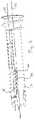
- FIG. 1shows an exploded perspective view of one embodiment of a toggle anchor assembly
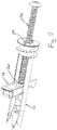
- FIG. 2shows an assembled perspective view of the anchor assembly with toggle nut in an anchoring orientation
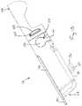
- FIG. 3shows a perspective view of the toggle body and the toggle nut, with toggle nut in an install orientation
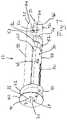
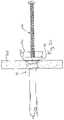
- FIG. 4shows a perspective view of fastener engagement with the toggle body, prior to toggle nut pivot
- FIG. 5an assembled perspective view of the anchor assembly, with the toggle nut pivoted into an anchoring orientation
- FIGS. 6-8show perspective views of the toggle body
- FIGS. 9 and 10show cross-section views of the toggle body
- FIGS. 11-14show perspective views of the toggle nut
- FIG. 15shows a side cross-section, with the toggle nut in the anchoring orientation
- FIG. 16shows an enlarged view of the pivot connection of FIG. 15 ;
- FIG. 17shows a perspective cross-section to see the pivot connection with the toggle nut in the install orientation
- FIG. 18shows a side cross-section with toggle nut in the install orientation
- FIGS. 19-22show a wall install and object mount sequence for the toggle anchor assembly
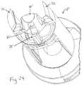
- FIGS. 23-25show an alternative embodiment of a toggle body for the anchor assembly.
- wallboardis generally used to refer to the most common wallboard such as drywall, but it is recognized that the anchor components could be suitable for any other friable wallboard material, such as dense corks or foams or other materials that can crumble. Accordingly, the term wallboard as used herein is intended to broadly encompass, for example, both typical drywall (aka plasterboard and gypsum board) and such other friable wallboard materials.
- a toggle anchor 10includes two main portions, specifically an elongated toggle body 12 and an elongated toggle nut 14 , as well as a screw 16 .
- the toggle body 12is formed of a die cast metal material and the toggle nut 14 is formed of a die cast metal material.
- the toggle bodybeing of plastic and the toggle nut being of metal.
- the toggle nut 14is loadable into the toggle body 12 by moving the toggle nut downward into a slot within the toggle body, per arrow 18 , near the driving end 20 of the toggle body. The toggle nut 14 is then moved within the slot per arrow 22 toward the wall boring end 24 of the toggle body until the toggle body reaches its mount position shown in FIG. 2 .
- the orientation of FIG. 2represents the anchoring orientation of the toggle anchor, in which the lengthwise axis 30 of the toggle nut 14 runs substantially perpendicular to the lengthwise axis 32 of the toggle body 12 .
- the toggle nut 14can be pivoted downward per arrow 26 to an install orientation, shown in FIG. 3 , in which the lengthwise axis 30 of the toggle nut runs substantially parallel to the lengthwise axis 32 of the toggle body.
- the install orientationis the orientation of the toggle anchor used for wall penetration.
- the toggle anchor 10can be reoriented from the install orientation to the anchoring orientation when the screw 16 is moved into an end opening 34 at the driving end of the toggle body and then along the toggle body so that the screw engages the toggle nut 14 per FIG. 4 , causing the toggle nut 14 to flip to the anchoring orientation.
- a threaded opening 36 of the toggle nut 14aligns with the screw 16 so that the screw will threadedly engaged the toggle nut, as shown in FIG. 5 , as the screw passes into and along the toggle body 12 .
- the driving end 20 of the toggle body 12includes a circular cylindrical body portion 40 with a high thread 42 formed thereon.
- the high thread 42will operate to engage with wallboard material to help retain the toggle body to a wall when initially installed.
- a flange 44with tapered forward facing or wall facing side, extends outward from the front end of portion 40 and will engage with the front surface of a wall to define the limit of penetration of the anchor.
- the forward facing side of the flange 44may include a set of ribs 46 that will bite into the wall surface and therefore reduce the likelihood of the toggle body rotating out of the wall.
- a pair of arms 48extend from body portion 40 toward the wall boring end 24 .
- the outer surface portions of the armsare circular cylinder in shape to match the circular cylinder shape of body portion 40 .
- the arms 48are spaced apart to define a toggle nut receiving slot 50 of the toggle body.
- the slot 50is open at both the top and the bottom along a majority of the slot length that extends between the body portion 40 and a connecting leg 52 that runs between the arms 48 .
- each arm 48includes recessed upper edge portions 54 toward the wall boring end of the toggle body.
- each arm 48includes a respective protruding guide rail 56 that runs from proximate the body portion 40 toward the wall boring end 24 .
- each rail 56is located along a lower portion of the slot 50 and runs to a distal location that is axially proximate to a short pivot bar 68 that also protrudes from the internal arm surface.
- One of the arms 48also includes a stop projection 60 located axially between the connecting leg 52 and the pivot bar 68 .
- the wall boring end 24 of the toggle body 12includes a pointed positioning tip 70 that will initially engage the wallboard, and a set of blade projections 72 (here three) disposed about the positioning tip. Two of the blade projections 72 are formed at the distal ends of the arms 48 . The third blade projection extends from a connecting leg 74 running between the arms 48 .
- the positioning tip 72is connected by supports 76 to the ends of the legs and by support 78 to the connecting leg 74 and third blade 72 .
- the positioning tip 70is formed with a convex surface portion 80 facing the third blade projection, and a concave surface portion 82 , where both surface portions taper to reduce in dimension toward the pointed free end of the tip.
- the positioning tip 70initially engages a wall surface and, as the toggle body is rotated, the forward cutting edges 84 of the blade projections 72 begin to move into the wall.
- the blade projections 72cut a clean hole in the wallboard, resulting in a wallboard hole without any flowering/drywall.
- the circular segment of wallboard that is cut by the boring end of the toggle bodymay be retained on the positioning tip 70 after the toggle body fully penetrates the wallboard.
- Outward facing surface portions 86 of the blade projections 72are all cylindrical and lie in a common circular cylindrical perimeter that runs parallel to the axis 32 of the toggle body, with the axis 32 positioned at the center of the common circular cylindrical perimeter.
- the toggle bodyFor the purpose of facilitating rotation of the toggle body 12 into wallboard, the toggle body includes a drive recess 88 at the driving end 20 of the toggle body.
- the drive recess 88is formed in part by the end opening 34 , which has radial extensions 90 to form slots for a screwdriver or drive bit.
- the toggle nut 14is formed by a body 110 with opposite sides 112 , a forward end 114 , a rearward end 116 and a bottom 118 .
- the rearward end 116includes an angled ramp surface 120 that is curved and bounded by sidewall segments 122 .
- Each side 112includes an elongated slide projection 124 and a pivot recess 126 .
- the slide projectionincludes a convex surface portion 128 facing toward the rearward end 116 .
- the pivot recess 126includes an entry throat 130 that leads to a circular main section 132 .
- the bottom side 118includes a downwardly protruding latch finger 134 with a rim, lip or segment 136 that projects slightly toward the rearward end 116 .
- an outwardly extending flange 138is provided forward of the axial location of the pivot recess 126 .
- the side flanges 138extend forward and around the front of the body 110 to form a forward flange 140 with a set of teeth 142 thereon.
- the teeth 142are formed by triangular serrations that can bite into a wallboard paper slug that is being cut and minimize dust pressure on the toggle nut, which can help to prevent toggle nut pivot during anchor assembly rotation through the wallboard.
- the serrated formalso helps to support the circular wallboard paper slug and keeps it in position parallel to the front wallboard surface during anchor assembly rotation through the wallboard, which can reduce wallboard fines or dust exiting the front wallboard surface.
- FIG. 17shows the relative orientation of each pivot bar 68 within its respective pivot recess 126 when the toggle nut 14 is in the install orientation.
- the latch finger 134engages with the forward end of the connecting leg 52 , as seen in FIG. 18 . As seen in FIGS.
- the connecting leg 52includes a forwardly protruding latch step 53 .
- the rearwardly extending segment 136 of the latch finger 134moves beneath the forwardly protruding latch step 53 , providing latching retention.
- the latching retentionis only a slight degree that can be overcome by sufficient rotational force applied to the toggle nut in the direction of arrow 150 about the pivot axis 152 that is centered on the main section of the pivot recess 126 .
- the positioning tip 70is placed against the surface of the wall 160 .
- a drive member 162is engaged into the drive recess of the forward end of the toggle body 12 and a force is applied toward the wall per arrow 164 , which will cause the positioning tip to begin to penetrate the wall 160 .
- a rotational torque, per arrow 166is also applied to the anchor 10 , which rotation will cause the blade projections 72 to bore a hole through the wall, enabling the anchor to be rotated into a stable and ready position per FIG. 20 , where the flange 44 is seated against the wall surface.
- the size of the hole in the wallcorresponds substantially to the size of the cylindrical outer surface of body portion 40 , so that the thread 42 engages into the wallboard material of the wall 160 with a good retention property.
- An object 170can then be mounted to the wall 160 using the screw 16 , by passing the screw through the object and into the anchor 10 . As the screw 16 moves further forward along the toggle body 12 , the distal tip of the screw contacts the rearward facing ramp surface 120 of the toggle nut, per FIG. 21 .
- the engaged connection between the pivot recess main section 132 and the pivot bar 68prevents axial movement of the toggle nut 14 along the length of the toggle body 12 .
- the interaction between the screw 16 and the ramp surface 120creates a rotational torque on the toggle nut that will progressively cause the toggle nut to rotate into the upright anchoring orientation so that the screw enters the threaded toggle nut hole 36 as seen in FIG. 5 , so that the anchor mounting operation achieves the set-up shown in FIG. 22 .
- the bottom of the toggle nut 14engages with the stop projection 60 of the toggle body 14 to define limit the rotation of the toggle nut during screw entry in order to assure that the toggle nut opening 36 remains aligned to receive the screw.
- FIGS. 23-25show an alternative embodiment of a toggle body 12 ′ that is similar in many respects to toggle body 12 , but with a variation at the wall boring end 24 ′.
- the positioning tip 70 ′is formed with an elongated through slot 85 aligns with a central blade projection 72 ′, where the extent of the central blade projection 72 ′ circumferentially is smaller than the extents of the side blade projections 72 circumferentially.
- This configuration, with narrower central blade projection 72 ′ in alignment with the slot 85facilitates simultaneous molding of the positioning tip 72 ′ and the central blade projection 72 ′.
- Still other variations and configurationsare possible.
Landscapes
- Engineering & Computer Science (AREA)
- General Engineering & Computer Science (AREA)
- Mechanical Engineering (AREA)
- Joining Of Building Structures In Genera (AREA)
- Dowels (AREA)
Abstract
Description
- (i) a pivot connection between the toggle nut and the toggle body, the pivot connection formed at least in part by a first pivot bar and a first pivot recess, wherein the first pivot bar projects into the slot from an inner side of the first arm of the toggle body, wherein the first pivot recess is defined in a first side surface of the toggle nut;
- (ii) the pivot connection also formed at least in part by a second pivot bar and a second pivot recess, wherein the second pivot bar projects into the slot from an inner side of the second arm of the toggle body, wherein the second pivot recess is defined in a second side surface of the toggle nut;
- (iii) the first arm includes a first recessed upper edge portion and the second arm includes a second recessed upper edge portion, wherein the toggle nut includes a first side flange and a second side flange, wherein, when the toggle nut is in the install orientation, the first side flange seats within the first recessed upper edge portion and the second side flange seats within the second recessed upper edge portion;
- (iv) the toggle nut includes a forwardly extending flange with a plurality of teeth;
- (v) the toggle body includes a connecting leg along a lower portion of the slot and that extends between the first and second arms, wherein the toggle nut includes a latch finger that engages with the connecting leg, when the toggle nut is in the install orientation, to releasably retain the toggle nut in the install orientation;
- (vi) the toggle body includes a driving end and a wall boring end, wherein, when the toggle nut is in the install orientation, the latch finger includes a latch segment that protrudes rearwardly toward the driving end of the toggle body and the connecting leg includes a latch step that protrudes forwardly toward the wall boring end of the toggle body, and the latch segment is captured at least partly beneath the latch step;
- (vii) the toggle body includes a driving end and a wall boring end, wherein the first arm of the toggle body includes a first guide rail projecting into the slot and the second arm of the toggle body includes a second guide rail projecting into the slot, wherein the toggle nut includes a first slide projection for engaging with a top of the first guide rail when the toggle nut is in the anchor orientation and moves toward the driving end of the toggle body, wherein the toggle nut includes a second slide projection for engaging with a top of the second guide rail when the toggle nut is in the anchor orientation and moves toward the driving end of the toggle body;
- (viii) the first slide projection includes a convex surface that engages the first guide rail and the second slide projection includes a second convex surface that engages the second guide rail;
- (ix) the toggle body includes a forward wall boring end formed by a positioning tip and a set of blade projections disposed about the positioning tip, wherein each blade projection includes a forward cutting edge, wherein the positioning tip is formed by a body with a convex surface portion and a concave surface portion;
- (x) the toggle body includes a forward wall boring end formed by a positioning tip and first, second and third blade projections disposed about the positioning tip, wherein the first blade projection is formed at a forward end of the first arm, the second blade projection is formed at a forward end of the second arm, and the third blade projection extends forwardly from a connecting leg that extends between the first arm and the second arm;
- (xi) the positioning tip extends forwardly from the connecting leg and is not connected to the first blade projection or the second blade projection.
Claims (18)
Priority Applications (1)
| Application Number | Priority Date | Filing Date | Title |
|---|---|---|---|
| US16/694,234US11486432B2 (en) | 2018-11-29 | 2019-11-25 | Anchor assembly with toggle |
Applications Claiming Priority (2)
| Application Number | Priority Date | Filing Date | Title |
|---|---|---|---|
| US201862772946P | 2018-11-29 | 2018-11-29 | |
| US16/694,234US11486432B2 (en) | 2018-11-29 | 2019-11-25 | Anchor assembly with toggle |
Publications (2)
| Publication Number | Publication Date |
|---|---|
| US20200173479A1 US20200173479A1 (en) | 2020-06-04 |
| US11486432B2true US11486432B2 (en) | 2022-11-01 |
Family
ID=70848370
Family Applications (1)
| Application Number | Title | Priority Date | Filing Date |
|---|---|---|---|
| US16/694,234Active2040-06-03US11486432B2 (en) | 2018-11-29 | 2019-11-25 | Anchor assembly with toggle |
Country Status (3)
| Country | Link |
|---|---|
| US (1) | US11486432B2 (en) |
| CA (1) | CA3062919A1 (en) |
| TW (1) | TW202033891A (en) |
Cited By (2)
| Publication number | Priority date | Publication date | Assignee | Title |
|---|---|---|---|---|
| US20220090737A1 (en)* | 2017-07-03 | 2022-03-24 | Gripple Limited | Anchor assembly |
| US20230047591A1 (en)* | 2021-08-11 | 2023-02-16 | Zhongshan Meitu Plastic Ind. Co., Ltd. | Fastening assembly |
Families Citing this family (2)
| Publication number | Priority date | Publication date | Assignee | Title |
|---|---|---|---|---|
| US11592053B2 (en)* | 2020-02-04 | 2023-02-28 | Rooftop Anchor, Inc. | Blind fasteners |
| USD1080370S1 (en)* | 2024-03-06 | 2025-06-24 | Weiqiao Xue | Drywall anchor |
Citations (74)
| Publication number | Priority date | Publication date | Assignee | Title |
|---|---|---|---|---|
| US549069A (en) | 1895-10-29 | Anchor-bolt | ||
| US918063A (en) | 1909-02-05 | 1909-04-13 | Gustav Klahre | Anchor-bolt. |
| US991427A (en) | 1911-02-18 | 1911-05-02 | Charles J Clements | Toggle-bolt. |
| US1084284A (en) | 1912-07-20 | 1914-01-13 | Henry B Newhall | Toggle-bolt. |
| US1145423A (en) | 1914-11-25 | 1915-07-06 | Carl Joseph | Toggle-bolt. |
| US1352919A (en) | 1917-09-14 | 1920-09-14 | Claude C Salmons | Combined clamp and fastener |
| US1373188A (en) | 1919-07-17 | 1921-03-29 | Diamond Expansion Bolt Co | Toggle |
| US1386202A (en) | 1918-07-24 | 1921-08-02 | U S Expansion Bolt Co | Attaching device |
| US1409626A (en) | 1920-11-16 | 1922-03-14 | Charles W Walther | Key bolt |
| US1516242A (en) | 1923-07-02 | 1924-11-18 | Ralph S Peirce | Anchorage device |
| US1733693A (en) | 1927-01-22 | 1929-10-29 | Edward A Porter | Toggle bolt |
| US1738133A (en) | 1927-04-19 | 1929-12-03 | Hart & Hutchinson Company | Toggle bolt |
| US2203146A (en) | 1938-06-25 | 1940-06-04 | Andrew M Hexdall | Fastening device |
| US2519511A (en) | 1947-04-29 | 1950-08-22 | Otto A Stelter | Anchor or toggle bolt |
| US2532040A (en) | 1948-05-11 | 1950-11-28 | Super Grip Anchor Bolt Co Inc | Toggle bolt |
| US2916235A (en)* | 1955-12-07 | 1959-12-08 | Nagel Siegfried Heinri Wilhelm | Article suspending hook structure |
| US3168850A (en)* | 1960-08-26 | 1965-02-09 | Leonard S Tennican | Toggle bolt |
| US3248994A (en) | 1963-02-26 | 1966-05-03 | Mortensen Aackersberg | Fastening device |
| US3605547A (en) | 1969-04-10 | 1971-09-20 | David I Millet | Self-aligning screw anchor |
| US3673910A (en) | 1968-09-09 | 1972-07-04 | Frank C Collister | Key bolt |
| US3707898A (en)* | 1971-09-08 | 1973-01-02 | Hollymatic Corp | Fastener |
| US3748697A (en) | 1971-12-20 | 1973-07-31 | L Marchese | Clamp assembly for hose, pipe and like articles |
| US3861267A (en) | 1968-09-09 | 1975-01-21 | Frank C Collister | Key bolt |
| US3872768A (en)* | 1973-12-20 | 1975-03-25 | Illinois Tool Works | Fastening device |
| US3980329A (en) | 1974-08-19 | 1976-09-14 | Loc-Coe | Manhole cover lock |
| US4075924A (en) | 1976-05-14 | 1978-02-28 | Mechanical Plastics Corporation | Anchor assembly for fastener |
| US4196883A (en) | 1977-12-22 | 1980-04-08 | Coats & Clark, Inc. | Hollow wall fastener |
| US4283986A (en) | 1979-09-26 | 1981-08-18 | Illinois Tool Works Inc. | Self-penetrating wallboard anchor |
| US4285264A (en) | 1979-05-15 | 1981-08-25 | Coats & Clark, Inc. | General purpose hollow wall toggle fastener |
| US4398855A (en) | 1981-04-06 | 1983-08-16 | Hultquist John V | Toggle type fastener |
| US4502826A (en) | 1983-05-16 | 1985-03-05 | Centre De Recherche Industrielle Du Quebec | Toggle fastener |
| US5046693A (en) | 1990-09-26 | 1991-09-10 | Browne William A | Microphone stand coupler |
| US5067864A (en)* | 1990-07-27 | 1991-11-26 | Illinois Tool Works Inc. | Self-drilling fastener for plasterboard wall |
| US5322401A (en)* | 1991-11-22 | 1994-06-21 | Societe De Prospection Et D'inventions Techniques | Dowel with rocker, cast in a single piece, and its method of casting |
| US5749687A (en)* | 1996-04-25 | 1998-05-12 | Kilgore, Iii; John C. | Wall toggle |
| US5876169A (en)* | 1997-04-21 | 1999-03-02 | W. A. Deutsher Pty Ltd | Threaded anchor |
| US6161999A (en) | 1999-01-29 | 2000-12-19 | Mechanical Plastics Corp. | Toggle bolt device |
| US6213701B1 (en) | 1999-03-23 | 2001-04-10 | Wakai & Co., Ltd. | Anchor |
| US6250865B1 (en)* | 1998-07-24 | 2001-06-26 | Cobra Anchors Co. Ltd | Screw tipped anchor assembly |
| US6491486B1 (en) | 1998-12-21 | 2002-12-10 | Fischerwerke Artur Fischer Gmbh & Co. Kg | Straddling dowel |
| US6679664B2 (en) | 2001-04-20 | 2004-01-20 | Wakai & Co., Ltd. | Plate nut assembly |
| US20040170486A1 (en) | 2003-02-28 | 2004-09-02 | Demeo Terenci G. | Toggle |
| US6821069B2 (en) | 2001-11-07 | 2004-11-23 | Wakai & Co., Ltd. | Anchor device |
| US6884012B2 (en) | 2003-09-04 | 2005-04-26 | Illinois Tool Works Inc. | Heavy duty toggle bolt fastener assembly, and method of installing and removing the same |
| US20050117996A1 (en) | 2003-12-02 | 2005-06-02 | Lemire Robert J. | Self-drilling fastener |
| US20060088399A1 (en) | 2004-02-23 | 2006-04-27 | Demeo Terenci G | Toggle |
| US20090053007A1 (en) | 2007-08-20 | 2009-02-26 | Givat Chaim Ichud | Retrievable toggle bolt with pivot-and-slide engagement |
| US7547171B2 (en)* | 2003-03-04 | 2009-06-16 | Cobra Anchors Co., Ltd. | Wall mounted toggle hook |
| US20090208310A1 (en) | 2008-02-14 | 2009-08-20 | Wakai & Co.,Ltd. | Anchoring device |
| US20090249738A1 (en) | 2004-10-22 | 2009-10-08 | Keith Anthony Brereton | Toggle pin |
| US7611316B2 (en)* | 2005-02-17 | 2009-11-03 | Illinois Tool Works Inc. | Heavy duty toggle bolt fastener for accommodating long screws and having properly positioned toggle nut component |
| USD605933S1 (en) | 2008-08-11 | 2009-12-15 | Powers Fasteners, Inc. | Anchor |
| US7736108B1 (en)* | 2007-09-06 | 2010-06-15 | Roofscreen Mfg. | Structural blind anchor bolt |
| US7828501B2 (en) | 2006-03-10 | 2010-11-09 | Moen Incorporated | Mounting mechanism |
| US7955392B2 (en)* | 2006-12-14 | 2011-06-07 | Warsaw Orthopedic, Inc. | Interspinous process devices and methods |
| US20110164941A1 (en) | 2007-08-16 | 2011-07-07 | Snead Robert T | Fastener Device |
| US8011080B2 (en) | 2008-09-14 | 2011-09-06 | International Patent Development Group, Llc | Hinged wall and ceiling anchor with fins and hinge |
| US20110262235A1 (en) | 2010-04-23 | 2011-10-27 | Garfield Theodore F | Reusable low cost drill for drywall |
| USD651890S1 (en) | 2010-05-04 | 2012-01-10 | Powers Products Iii, Llc | Wall anchor |
| US8128329B2 (en) | 2007-12-31 | 2012-03-06 | Jean Pilon | Wall anchor |
| US8303224B2 (en) | 2005-03-21 | 2012-11-06 | Cobra Anchors Co. Ltd. | Anchor assembly for fastener |
| US8388290B2 (en) | 2009-12-17 | 2013-03-05 | Matthew Wiggins | Mounting system and method |
| US8444358B2 (en) | 2010-05-03 | 2013-05-21 | Black & Decker Inc. | Wall anchor |
| US8449236B2 (en)* | 2005-03-21 | 2013-05-28 | Cobra Fixations Cie Ltee—Cobra Anchors Co. Ltd. | Anchor assembly with toggle for hollow walls |
| US8858143B2 (en) | 2010-05-03 | 2014-10-14 | Black & Decker Inc. | Wall anchor |
| US20150043989A1 (en) | 2012-03-08 | 2015-02-12 | Contendor Ab | Wall screw anchor |
| US20160131304A1 (en) | 2013-10-22 | 2016-05-12 | James Roberts | Drywall brace and method for installing |
| US9447556B2 (en) | 2012-10-19 | 2016-09-20 | L & P Property Management Company | Bullet anchor system |
| WO2017055060A1 (en) | 2015-09-29 | 2017-04-06 | Fischerwerke Gmbh & Co. Kg | Pivoting dowel |
| WO2017177256A1 (en) | 2016-04-14 | 2017-10-19 | Bradken Resources Pty Ltd | Fastener device, method and system |
| US20170307000A1 (en) | 2014-10-24 | 2017-10-26 | Fischerwerke Gmbh & Co. Kg | Toggle fixing |
| US20170314600A1 (en) | 2014-10-24 | 2017-11-02 | Fischerwerke Gmbh & Co. Kg | Toggle fixing and method of mounting a toggle fixing |
| US20180073538A1 (en) | 2015-04-15 | 2018-03-15 | Fischerwerke Gmbh & Co. Kg | Toggle fixing |
| WO2018102902A1 (en) | 2016-12-08 | 2018-06-14 | Cobra Fixations Cie Ltee - Cobra Anchors Co. Ltd. | Anchor assembly for fastener |
- 2019
- 2019-11-25USUS16/694,234patent/US11486432B2/enactiveActive
- 2019-11-27TWTW108143085Apatent/TW202033891A/enunknown
- 2019-11-27CACA3062919Apatent/CA3062919A1/enactivePending
Patent Citations (82)
| Publication number | Priority date | Publication date | Assignee | Title |
|---|---|---|---|---|
| US549069A (en) | 1895-10-29 | Anchor-bolt | ||
| US918063A (en) | 1909-02-05 | 1909-04-13 | Gustav Klahre | Anchor-bolt. |
| US991427A (en) | 1911-02-18 | 1911-05-02 | Charles J Clements | Toggle-bolt. |
| US1084284A (en) | 1912-07-20 | 1914-01-13 | Henry B Newhall | Toggle-bolt. |
| US1145423A (en) | 1914-11-25 | 1915-07-06 | Carl Joseph | Toggle-bolt. |
| US1352919A (en) | 1917-09-14 | 1920-09-14 | Claude C Salmons | Combined clamp and fastener |
| US1386202A (en) | 1918-07-24 | 1921-08-02 | U S Expansion Bolt Co | Attaching device |
| US1373188A (en) | 1919-07-17 | 1921-03-29 | Diamond Expansion Bolt Co | Toggle |
| US1409626A (en) | 1920-11-16 | 1922-03-14 | Charles W Walther | Key bolt |
| US1516242A (en) | 1923-07-02 | 1924-11-18 | Ralph S Peirce | Anchorage device |
| US1733693A (en) | 1927-01-22 | 1929-10-29 | Edward A Porter | Toggle bolt |
| US1738133A (en) | 1927-04-19 | 1929-12-03 | Hart & Hutchinson Company | Toggle bolt |
| US2203146A (en) | 1938-06-25 | 1940-06-04 | Andrew M Hexdall | Fastening device |
| US2519511A (en) | 1947-04-29 | 1950-08-22 | Otto A Stelter | Anchor or toggle bolt |
| US2532040A (en) | 1948-05-11 | 1950-11-28 | Super Grip Anchor Bolt Co Inc | Toggle bolt |
| US2916235A (en)* | 1955-12-07 | 1959-12-08 | Nagel Siegfried Heinri Wilhelm | Article suspending hook structure |
| US3168850A (en)* | 1960-08-26 | 1965-02-09 | Leonard S Tennican | Toggle bolt |
| US3248994A (en) | 1963-02-26 | 1966-05-03 | Mortensen Aackersberg | Fastening device |
| US3673910A (en) | 1968-09-09 | 1972-07-04 | Frank C Collister | Key bolt |
| US3861267A (en) | 1968-09-09 | 1975-01-21 | Frank C Collister | Key bolt |
| US3605547A (en) | 1969-04-10 | 1971-09-20 | David I Millet | Self-aligning screw anchor |
| US3707898A (en)* | 1971-09-08 | 1973-01-02 | Hollymatic Corp | Fastener |
| US3748697A (en) | 1971-12-20 | 1973-07-31 | L Marchese | Clamp assembly for hose, pipe and like articles |
| US3872768A (en)* | 1973-12-20 | 1975-03-25 | Illinois Tool Works | Fastening device |
| US3980329A (en) | 1974-08-19 | 1976-09-14 | Loc-Coe | Manhole cover lock |
| US4075924A (en) | 1976-05-14 | 1978-02-28 | Mechanical Plastics Corporation | Anchor assembly for fastener |
| US4196883A (en) | 1977-12-22 | 1980-04-08 | Coats & Clark, Inc. | Hollow wall fastener |
| US4285264A (en) | 1979-05-15 | 1981-08-25 | Coats & Clark, Inc. | General purpose hollow wall toggle fastener |
| US4283986A (en) | 1979-09-26 | 1981-08-18 | Illinois Tool Works Inc. | Self-penetrating wallboard anchor |
| US4398855A (en) | 1981-04-06 | 1983-08-16 | Hultquist John V | Toggle type fastener |
| US4502826A (en) | 1983-05-16 | 1985-03-05 | Centre De Recherche Industrielle Du Quebec | Toggle fastener |
| US5067864A (en)* | 1990-07-27 | 1991-11-26 | Illinois Tool Works Inc. | Self-drilling fastener for plasterboard wall |
| US5046693A (en) | 1990-09-26 | 1991-09-10 | Browne William A | Microphone stand coupler |
| US5322401A (en)* | 1991-11-22 | 1994-06-21 | Societe De Prospection Et D'inventions Techniques | Dowel with rocker, cast in a single piece, and its method of casting |
| US5749687A (en)* | 1996-04-25 | 1998-05-12 | Kilgore, Iii; John C. | Wall toggle |
| US5876169A (en)* | 1997-04-21 | 1999-03-02 | W. A. Deutsher Pty Ltd | Threaded anchor |
| US6250865B1 (en)* | 1998-07-24 | 2001-06-26 | Cobra Anchors Co. Ltd | Screw tipped anchor assembly |
| US6491486B1 (en) | 1998-12-21 | 2002-12-10 | Fischerwerke Artur Fischer Gmbh & Co. Kg | Straddling dowel |
| US6161999A (en) | 1999-01-29 | 2000-12-19 | Mechanical Plastics Corp. | Toggle bolt device |
| US6213701B1 (en) | 1999-03-23 | 2001-04-10 | Wakai & Co., Ltd. | Anchor |
| US6679664B2 (en) | 2001-04-20 | 2004-01-20 | Wakai & Co., Ltd. | Plate nut assembly |
| US6821069B2 (en) | 2001-11-07 | 2004-11-23 | Wakai & Co., Ltd. | Anchor device |
| US20040170486A1 (en) | 2003-02-28 | 2004-09-02 | Demeo Terenci G. | Toggle |
| US8573913B2 (en) | 2003-03-04 | 2013-11-05 | Cobra Fixations Cie. Ltee—Cobra Anchors Co. Ltd. | Wall mounted toggle hook |
| US7547171B2 (en)* | 2003-03-04 | 2009-06-16 | Cobra Anchors Co., Ltd. | Wall mounted toggle hook |
| US20140199132A1 (en) | 2003-03-04 | 2014-07-17 | Cobra Fixations Cie. Ltee.-Cobra Anchors Co. Ltd. | Wall Mounted Toggle Hook |
| US6884012B2 (en) | 2003-09-04 | 2005-04-26 | Illinois Tool Works Inc. | Heavy duty toggle bolt fastener assembly, and method of installing and removing the same |
| US20050117996A1 (en) | 2003-12-02 | 2005-06-02 | Lemire Robert J. | Self-drilling fastener |
| US20060088399A1 (en) | 2004-02-23 | 2006-04-27 | Demeo Terenci G | Toggle |
| US20090249738A1 (en) | 2004-10-22 | 2009-10-08 | Keith Anthony Brereton | Toggle pin |
| US7611316B2 (en)* | 2005-02-17 | 2009-11-03 | Illinois Tool Works Inc. | Heavy duty toggle bolt fastener for accommodating long screws and having properly positioned toggle nut component |
| US20170102020A1 (en) | 2005-03-21 | 2017-04-13 | Cobra Fixations Cie Ltee.-Cobra Anchors Co. Ltd. | Anchor assembly for fastener |
| US8449236B2 (en)* | 2005-03-21 | 2013-05-28 | Cobra Fixations Cie Ltee—Cobra Anchors Co. Ltd. | Anchor assembly with toggle for hollow walls |
| US9587661B2 (en) | 2005-03-21 | 2017-03-07 | Cobra Fixations Cie Ltee—Cobra Anchors Co. Ltd. | Anchor assembly with toggle for hollow walls |
| US9394932B2 (en) | 2005-03-21 | 2016-07-19 | Cobra Fixations Cie Ltee.-Cobra Anchors Co. Ltd. | Anchor assembly for fastener |
| US8821094B2 (en) | 2005-03-21 | 2014-09-02 | Cobra Fixations Cie Ltee-Cobra Anchors Co. Ltd. | Anchor assembly with toggle for hollow walls |
| US8303224B2 (en) | 2005-03-21 | 2012-11-06 | Cobra Anchors Co. Ltd. | Anchor assembly for fastener |
| US7828501B2 (en) | 2006-03-10 | 2010-11-09 | Moen Incorporated | Mounting mechanism |
| US7955392B2 (en)* | 2006-12-14 | 2011-06-07 | Warsaw Orthopedic, Inc. | Interspinous process devices and methods |
| US20110164941A1 (en) | 2007-08-16 | 2011-07-07 | Snead Robert T | Fastener Device |
| US20090053007A1 (en) | 2007-08-20 | 2009-02-26 | Givat Chaim Ichud | Retrievable toggle bolt with pivot-and-slide engagement |
| US7736108B1 (en)* | 2007-09-06 | 2010-06-15 | Roofscreen Mfg. | Structural blind anchor bolt |
| US8128329B2 (en) | 2007-12-31 | 2012-03-06 | Jean Pilon | Wall anchor |
| US20090208310A1 (en) | 2008-02-14 | 2009-08-20 | Wakai & Co.,Ltd. | Anchoring device |
| USD605933S1 (en) | 2008-08-11 | 2009-12-15 | Powers Fasteners, Inc. | Anchor |
| US8235635B1 (en) | 2008-09-14 | 2012-08-07 | International Patent Development Group, Llc | Wall and ceiling anchor with fins and hinge |
| US8011080B2 (en) | 2008-09-14 | 2011-09-06 | International Patent Development Group, Llc | Hinged wall and ceiling anchor with fins and hinge |
| US8388290B2 (en) | 2009-12-17 | 2013-03-05 | Matthew Wiggins | Mounting system and method |
| US20110262235A1 (en) | 2010-04-23 | 2011-10-27 | Garfield Theodore F | Reusable low cost drill for drywall |
| US8444358B2 (en) | 2010-05-03 | 2013-05-21 | Black & Decker Inc. | Wall anchor |
| US8858143B2 (en) | 2010-05-03 | 2014-10-14 | Black & Decker Inc. | Wall anchor |
| US8568075B2 (en) | 2010-05-03 | 2013-10-29 | Black & Decker Inc. | Wall anchor |
| USD651890S1 (en) | 2010-05-04 | 2012-01-10 | Powers Products Iii, Llc | Wall anchor |
| US20150043989A1 (en) | 2012-03-08 | 2015-02-12 | Contendor Ab | Wall screw anchor |
| US9447556B2 (en) | 2012-10-19 | 2016-09-20 | L & P Property Management Company | Bullet anchor system |
| US20160131304A1 (en) | 2013-10-22 | 2016-05-12 | James Roberts | Drywall brace and method for installing |
| US20170307000A1 (en) | 2014-10-24 | 2017-10-26 | Fischerwerke Gmbh & Co. Kg | Toggle fixing |
| US20170314600A1 (en) | 2014-10-24 | 2017-11-02 | Fischerwerke Gmbh & Co. Kg | Toggle fixing and method of mounting a toggle fixing |
| US20180073538A1 (en) | 2015-04-15 | 2018-03-15 | Fischerwerke Gmbh & Co. Kg | Toggle fixing |
| WO2017055060A1 (en) | 2015-09-29 | 2017-04-06 | Fischerwerke Gmbh & Co. Kg | Pivoting dowel |
| WO2017177256A1 (en) | 2016-04-14 | 2017-10-19 | Bradken Resources Pty Ltd | Fastener device, method and system |
| WO2018102902A1 (en) | 2016-12-08 | 2018-06-14 | Cobra Fixations Cie Ltee - Cobra Anchors Co. Ltd. | Anchor assembly for fastener |
Non-Patent Citations (1)
| Title |
|---|
| U.S. Appl. No. 16/694,227. |
Cited By (4)
| Publication number | Priority date | Publication date | Assignee | Title |
|---|---|---|---|---|
| US20220090737A1 (en)* | 2017-07-03 | 2022-03-24 | Gripple Limited | Anchor assembly |
| US11754223B2 (en)* | 2017-07-03 | 2023-09-12 | Gripple Limited | Anchor assembly |
| US20230047591A1 (en)* | 2021-08-11 | 2023-02-16 | Zhongshan Meitu Plastic Ind. Co., Ltd. | Fastening assembly |
| US12031562B2 (en)* | 2021-08-11 | 2024-07-09 | Zhongshan Meitu Plastic Ind. Co., Ltd. | Fastening assembly |
Also Published As
| Publication number | Publication date |
|---|---|
| CA3062919A1 (en) | 2020-05-29 |
| TW202033891A (en) | 2020-09-16 |
| US20200173479A1 (en) | 2020-06-04 |
Similar Documents
| Publication | Publication Date | Title |
|---|---|---|
| US11486432B2 (en) | Anchor assembly with toggle | |
| US10837480B2 (en) | Hollow wall anchor | |
| JP2008533410A (en) | Anchor assembly for fixture | |
| US20120045276A1 (en) | Twist-lock T-clamp | |
| JP3930960B2 (en) | Threaded anchor | |
| JP5129114B2 (en) | Anchor assembly with toggle for hollow wall | |
| WO2005017374A1 (en) | Blind bolt and blind nut | |
| JP3287587B2 (en) | Fastener | |
| EP0874168B1 (en) | Threaded anchor | |
| US4283986A (en) | Self-penetrating wallboard anchor | |
| US8459920B2 (en) | Fastener | |
| US6213701B1 (en) | Anchor | |
| US20180109084A1 (en) | Wire shear anvil tool | |
| KR960012156B1 (en) | Screw fastener | |
| US11655837B2 (en) | Anchor assembly with toggle | |
| JP2002168222A (en) | Nut | |
| KR20140107884A (en) | Cross bar connecting device | |
| JP7461256B2 (en) | Chuck Unit | |
| US1036858A (en) | Toggle-nut. | |
| KR200413107Y1 (en) | Segment Mold with Socket Retainer | |
| JP2001310206A (en) | Tool holder | |
| JP3267538B2 (en) | Vice | |
| JP2017154224A (en) | Rotating board | |
| JP2507641Y2 (en) | Anchor bolt | |
| AU2019232840A1 (en) | Anchor assembly for fastener |
Legal Events
| Date | Code | Title | Description |
|---|---|---|---|
| FEPP | Fee payment procedure | Free format text:ENTITY STATUS SET TO UNDISCOUNTED (ORIGINAL EVENT CODE: BIG.); ENTITY STATUS OF PATENT OWNER: LARGE ENTITY | |
| STPP | Information on status: patent application and granting procedure in general | Free format text:APPLICATION DISPATCHED FROM PREEXAM, NOT YET DOCKETED | |
| STPP | Information on status: patent application and granting procedure in general | Free format text:DOCKETED NEW CASE - READY FOR EXAMINATION | |
| AS | Assignment | Owner name:BARCLAYS BANK PLC, AS ADMINISTRATIVE AGENT, NEW YORK Free format text:ABL PATENT SECURITY AGREEMENT SUPPLEMENT;ASSIGNOR:THE HILLMAN GROUP, INC.;REEL/FRAME:056884/0581 Effective date:20210714 Owner name:JEFFERIES FINANCE LLC, AS ADMINISTRATIVE AGENT, NEW YORK Free format text:TERM PATENT SECURITY AGREEMENT;ASSIGNOR:THE HILLMAN GROUP, INC.;REEL/FRAME:056883/0001 Effective date:20210714 | |
| STPP | Information on status: patent application and granting procedure in general | Free format text:NON FINAL ACTION MAILED | |
| AS | Assignment | Owner name:THE HILLMAN GROUP, INC., OHIO Free format text:ASSIGNMENT OF ASSIGNORS INTEREST;ASSIGNOR:MAHADEO, BEESHAM;REEL/FRAME:058259/0614 Effective date:20211130 | |
| STPP | Information on status: patent application and granting procedure in general | Free format text:NON FINAL ACTION MAILED | |
| STPP | Information on status: patent application and granting procedure in general | Free format text:RESPONSE TO NON-FINAL OFFICE ACTION ENTERED AND FORWARDED TO EXAMINER | |
| STPP | Information on status: patent application and granting procedure in general | Free format text:FINAL REJECTION MAILED | |
| STPP | Information on status: patent application and granting procedure in general | Free format text:NOTICE OF ALLOWANCE MAILED -- APPLICATION RECEIVED IN OFFICE OF PUBLICATIONS | |
| STPP | Information on status: patent application and granting procedure in general | Free format text:PUBLICATIONS -- ISSUE FEE PAYMENT VERIFIED | |
| STCF | Information on status: patent grant | Free format text:PATENTED CASE |