US11485493B2 - Using a cellular interface for Unmanned Aerial Vehicle communications - Google Patents
Using a cellular interface for Unmanned Aerial Vehicle communicationsDownload PDFInfo
- Publication number
- US11485493B2 US11485493B2US16/958,325US201716958325AUS11485493B2US 11485493 B2US11485493 B2US 11485493B2US 201716958325 AUS201716958325 AUS 201716958325AUS 11485493 B2US11485493 B2US 11485493B2
- Authority
- US
- United States
- Prior art keywords
- uav
- management service
- control management
- radio control
- determining
- Prior art date
- Legal status (The legal status is an assumption and is not a legal conclusion. Google has not performed a legal analysis and makes no representation as to the accuracy of the status listed.)
- Active, expires
Links
- 238000004891communicationMethods0.000titleclaimsabstractdescription53
- 230000001413cellular effectEffects0.000titledescription40
- 238000000034methodMethods0.000claimsabstractdescription40
- 230000004044responseEffects0.000claimsabstractdescription24
- 238000013475authorizationMethods0.000claimsdescription11
- 230000033001locomotionEffects0.000claimsdescription5
- 238000007726management methodMethods0.000description68
- 230000006855networkingEffects0.000description13
- 230000005540biological transmissionEffects0.000description11
- 230000001276controlling effectEffects0.000description9
- 238000010586diagramMethods0.000description9
- 238000004590computer programMethods0.000description4
- 230000003287optical effectEffects0.000description4
- 238000013439planningMethods0.000description4
- 230000000153supplemental effectEffects0.000description4
- 230000010006flightEffects0.000description3
- 238000012545processingMethods0.000description3
- RZVHIXYEVGDQDX-UHFFFAOYSA-N9,10-anthraquinoneChemical compoundC1=CC=C2C(=O)C3=CC=CC=C3C(=O)C2=C1RZVHIXYEVGDQDX-UHFFFAOYSA-N0.000description2
- 230000008859changeEffects0.000description2
- 238000005516engineering processMethods0.000description2
- 230000007774longtermEffects0.000description2
- 238000010295mobile communicationMethods0.000description2
- 230000000644propagated effectEffects0.000description2
- 230000001105regulatory effectEffects0.000description2
- 239000007787solidSubstances0.000description2
- 230000003068static effectEffects0.000description2
- 238000012546transferMethods0.000description2
- 230000001960triggered effectEffects0.000description2
- 230000005641tunnelingEffects0.000description2
- 230000001133accelerationEffects0.000description1
- 230000009471actionEffects0.000description1
- 230000004075alterationEffects0.000description1
- 230000001419dependent effectEffects0.000description1
- 238000013461designMethods0.000description1
- 230000009977dual effectEffects0.000description1
- 230000000694effectsEffects0.000description1
- 230000005611electricityEffects0.000description1
- 238000005538encapsulationMethods0.000description1
- 230000006870functionEffects0.000description1
- 230000003993interactionEffects0.000description1
- 230000007246mechanismEffects0.000description1
- 230000004048modificationEffects0.000description1
- 238000012986modificationMethods0.000description1
- 238000012544monitoring processMethods0.000description1
- 239000012466permeateSubstances0.000description1
- 230000001902propagating effectEffects0.000description1
- 230000011664signalingEffects0.000description1
- 230000007704transitionEffects0.000description1
- 238000012384transportation and deliveryMethods0.000description1
Images


Classifications
- B—PERFORMING OPERATIONS; TRANSPORTING
- B64—AIRCRAFT; AVIATION; COSMONAUTICS
- B64C—AEROPLANES; HELICOPTERS
- B64C39/00—Aircraft not otherwise provided for
- B64C39/02—Aircraft not otherwise provided for characterised by special use
- B64C39/024—Aircraft not otherwise provided for characterised by special use of the remote controlled vehicle type, i.e. RPV
- G—PHYSICS
- G05—CONTROLLING; REGULATING
- G05D—SYSTEMS FOR CONTROLLING OR REGULATING NON-ELECTRIC VARIABLES
- G05D1/00—Control of position, course, altitude or attitude of land, water, air or space vehicles, e.g. using automatic pilots
- G05D1/0011—Control of position, course, altitude or attitude of land, water, air or space vehicles, e.g. using automatic pilots associated with a remote control arrangement
- G05D1/0022—Control of position, course, altitude or attitude of land, water, air or space vehicles, e.g. using automatic pilots associated with a remote control arrangement characterised by the communication link
- G08G5/0013—
- G08G5/0034—
- G08G5/0069—
- G—PHYSICS
- G08—SIGNALLING
- G08G—TRAFFIC CONTROL SYSTEMS
- G08G5/00—Traffic control systems for aircraft
- G08G5/20—Arrangements for acquiring, generating, sharing or displaying traffic information
- G08G5/21—Arrangements for acquiring, generating, sharing or displaying traffic information located onboard the aircraft
- G—PHYSICS
- G08—SIGNALLING
- G08G—TRAFFIC CONTROL SYSTEMS
- G08G5/00—Traffic control systems for aircraft
- G08G5/20—Arrangements for acquiring, generating, sharing or displaying traffic information
- G08G5/25—Transmission of traffic-related information between aircraft
- G—PHYSICS
- G08—SIGNALLING
- G08G—TRAFFIC CONTROL SYSTEMS
- G08G5/00—Traffic control systems for aircraft
- G08G5/20—Arrangements for acquiring, generating, sharing or displaying traffic information
- G08G5/26—Transmission of traffic-related information between aircraft and ground stations
- G—PHYSICS
- G08—SIGNALLING
- G08G—TRAFFIC CONTROL SYSTEMS
- G08G5/00—Traffic control systems for aircraft
- G08G5/30—Flight plan management
- G08G5/32—Flight plan management for flight plan preparation
- G—PHYSICS
- G08—SIGNALLING
- G08G—TRAFFIC CONTROL SYSTEMS
- G08G5/00—Traffic control systems for aircraft
- G08G5/50—Navigation or guidance aids
- G08G5/55—Navigation or guidance aids for a single aircraft
- G—PHYSICS
- G08—SIGNALLING
- G08G—TRAFFIC CONTROL SYSTEMS
- G08G5/00—Traffic control systems for aircraft
- G08G5/50—Navigation or guidance aids
- G08G5/57—Navigation or guidance aids for unmanned aircraft
- H—ELECTRICITY
- H04—ELECTRIC COMMUNICATION TECHNIQUE
- H04B—TRANSMISSION
- H04B7/00—Radio transmission systems, i.e. using radiation field
- H04B7/14—Relay systems
- H04B7/15—Active relay systems
- H04B7/185—Space-based or airborne stations; Stations for satellite systems
- H04B7/18502—Airborne stations
- H04B7/18504—Aircraft used as relay or high altitude atmospheric platform
- H—ELECTRICITY
- H04—ELECTRIC COMMUNICATION TECHNIQUE
- H04W—WIRELESS COMMUNICATION NETWORKS
- H04W4/00—Services specially adapted for wireless communication networks; Facilities therefor
- H—ELECTRICITY
- H04—ELECTRIC COMMUNICATION TECHNIQUE
- H04W—WIRELESS COMMUNICATION NETWORKS
- H04W4/00—Services specially adapted for wireless communication networks; Facilities therefor
- H04W4/02—Services making use of location information
- H04W4/029—Location-based management or tracking services
- H—ELECTRICITY
- H04—ELECTRIC COMMUNICATION TECHNIQUE
- H04W—WIRELESS COMMUNICATION NETWORKS
- H04W76/00—Connection management
- H04W76/10—Connection setup
- H04W76/12—Setup of transport tunnels
- B64C2201/146—
- B—PERFORMING OPERATIONS; TRANSPORTING
- B64—AIRCRAFT; AVIATION; COSMONAUTICS
- B64U—UNMANNED AERIAL VEHICLES [UAV]; EQUIPMENT THEREFOR
- B64U10/00—Type of UAV
- B64U10/10—Rotorcrafts
- B64U10/13—Flying platforms
- B—PERFORMING OPERATIONS; TRANSPORTING
- B64—AIRCRAFT; AVIATION; COSMONAUTICS
- B64U—UNMANNED AERIAL VEHICLES [UAV]; EQUIPMENT THEREFOR
- B64U2201/00—UAVs characterised by their flight controls
- B64U2201/20—Remote controls
- G—PHYSICS
- G08—SIGNALLING
- G08G—TRAFFIC CONTROL SYSTEMS
- G08G5/00—Traffic control systems for aircraft
- G08G5/50—Navigation or guidance aids
- G08G5/59—Navigation or guidance aids in accordance with predefined flight zones, e.g. to avoid prohibited zones
- H—ELECTRICITY
- H04—ELECTRIC COMMUNICATION TECHNIQUE
- H04W—WIRELESS COMMUNICATION NETWORKS
- H04W4/00—Services specially adapted for wireless communication networks; Facilities therefor
- H04W4/02—Services making use of location information
- H04W4/021—Services related to particular areas, e.g. point of interest [POI] services, venue services or geofences
Definitions
- Embodiments of the inventionrelate to the field of controlling Unmanned Aerial Vehicles (UAVs); and more specifically, to managing connections between UAVs and associated UAV devices, including radio controllers, using cellular services.
- UAVsUnmanned Aerial Vehicles
- UAVsUnmanned Aerial Vehicles
- delivery servicesaerial photography and film making, remote sensing tasks for agriculture, city planning, civil engineering, support for public safety and rescue services, and much more.
- UAVsare manually flown by a UAV operator while in other scenarios a UAV engages in fully or partially autonomous flight where a UAV operator may be monitoring multiple aircraft simultaneously and intervening only when issues arise.
- a control channelis needed between the UAV and the controller for controlling the flight of the UAV.
- this control channelis implemented through the use of a radio controller that operates with a line-of-sight control interface.
- This line-of-sight control interface/channelallows for control of UAVs over an operating distance (dictated by transmission constraints of the interface/channel) and while obstructions are not present between the UAV and the radio controller. Once the UAV extends beyond the operating distance of the line-of-sight control interface, the UAV is forced to fly without controller/operator input.
- a method for managing connections between an Unmanned Aerial Vehicle (UAV) and one or more associated UAV devicesincludes determining, by a radio control management service, that one or more associated UAV devices are attached to a wireless network; determining, by the radio control management service, that one or more UAVs are attached to the wireless network; and routing, by the radio control management service in response to determining that the one or more associated UAV devices and one or more UAVs are attached to the network, at least one of (1) communications from at least one of the one or more UAVs to at least one of the one or more associated UAV devices and (2) communications from at least one of the one or more associated UAV devices to at least one of the one or more UAVs.
- UAVUnmanned Aerial Vehicle
- the methods, systems, and devices described hereinmay facilitate the use of a wireless cellular network (e.g., a 3rd Generation Partnership Project (3GPP) system) to connect UAVs and associated UAV devices (e.g., radio controllers and/or telemetry computers).
- a wireless cellular networke.g., a 3rd Generation Partnership Project (3GPP) system
- UAVs and associated UAV devicese.g., radio controllers and/or telemetry computers.
- a radio control (RC) management servicemay be employed to intelligently route communications between UAVs and associated UAV devices attached to the wireless cellular network.
- cellular networksprovide high bandwidth for the transmission of large volumes of data (e.g., telemetry, video, and image data and/or complex flight commands) and consistent, long-range coverage.
- datae.g., telemetry, video, and image data and/or complex flight commands
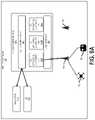
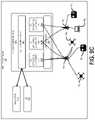
- FIG. 1illustrates an air traffic system, including an Unmanned Aerial Vehicle (UAV) Traffic Management (UTM) system and a 3rd Generation Partnership Project (3GPP) system, according to one embodiment;
- UAVUnmanned Aerial Vehicle
- UPMTraffic Management
- 3GPP3rd Generation Partnership Project
- FIG. 2illustrates an example flight plan with a set of coordinates according to one embodiment
- FIG. 3illustrates an example flight plan with a set of restricted areas/zones according to one embodiment
- FIG. 4illustrates an example flight plan with a designated clearance zone according to one embodiment
- FIG. 5illustrates a block diagram of a UAV according to one embodiment
- FIG. 6illustrates a block diagram of an associated UAV device according to one embodiment
- FIG. 7illustrates a method for managing connections between one or more UAVs and one or more associated UAV devices according to one embodiment
- FIG. 8Aillustrates an example of a radio control (RC) management service according to one embodiment
- FIG. 8Billustrates an example set of modules that may be run in a virtual machine of a RC application according to one embodiment
- FIG. 9Ashows a first UAV and a first associated UAV device communicating via an RC application according to one embodiment
- FIG. 9Bshows a second UAV and a second associated UAV device communicating via an RC application according to one embodiment
- FIG. 9Cshows the second UAV and a third associated UAV device communicating via an RC application according to one embodiment
- FIG. 10shows a flow diagram for routing communications between a UAV and associated UAV device during a handover between cells according to one embodiment
- FIG. 11illustrates a computing/networking device according to one embodiment.
- Bracketed text and blocks with dashed bordersare used herein to illustrate optional operations that add additional features to embodiments of the invention. However, such notation should not be taken to mean that these are the only options or optional operations, and/or that blocks with solid borders are not optional in certain embodiments of the invention.
- references in the specification to “one embodiment,” “an embodiment,” “an example embodiment,” etc.,indicate that the embodiment described may include a particular feature, structure, or characteristic, but every embodiment may not necessarily include the particular feature, structure, or characteristic. Moreover, such phrases are not necessarily referring to the same embodiment. Further, when a particular feature, structure, or characteristic is described in connection with an embodiment, it is submitted that it is within the knowledge of one skilled in the art to affect such feature, structure, or characteristic in connection with other embodiments whether or not explicitly described.
- Coupledis used to indicate that two or more elements, which may or may not be in direct physical or electrical contact with each other, co-operate or interact with each other.
- Connectedis used to indicate the establishment of communication between two or more elements that are coupled with each other.
- An electronic devicestores and transmits (internally and/or with other electronic devices over a network) code (which is composed of software instructions and which is sometimes referred to as computer program code or a computer program) and/or data using machine-readable media (also called computer-readable media), such as machine-readable storage media (e.g., magnetic disks, optical disks, read only memory (ROM), flash memory devices, phase change memory) and machine-readable transmission media (also called a carrier) (e.g., electrical, optical, radio, acoustical or other form of propagated signals—such as carrier waves, infrared signals).
- machine-readable mediaalso called computer-readable media
- machine-readable storage mediae.g., magnetic disks, optical disks, read only memory (ROM), flash memory devices, phase change memory
- machine-readable transmission mediaalso called a carrier
- carriere.g., electrical, optical, radio, acoustical or other form of propagated signals—such as carrier waves, infrared signals.
- an electronic devicee.g., a computer
- includes hardware and softwaresuch as a set of one or more processors coupled to one or more machine-readable storage media to store code for execution on the set of processors and/or to store data.
- an electronic devicemay include non-volatile memory containing the code since the non-volatile memory can persist the code even when the electronic device is turned off, and while the electronic device is turned on that part of the code that is to be executed by the processor(s) of that electronic device is copied from the slower non-volatile memory into volatile memory (e.g., dynamic random-access memory (DRAM), static random-access memory (SRAM)) of that electronic device.
- volatile memorye.g., dynamic random-access memory (DRAM), static random-access memory (SRAM)
- Typical electronic devicesalso include a set or one or more physical network interface(s) to establish network connections (to transmit and/or receive code and/or data using propagating signals) with other electronic devices.
- network connectionsto transmit and/or receive code and/or data using propagating signals.
- One or more parts of an embodiment of the inventionmay be implemented using different combinations of software, firmware, and/or hardware.
- an associated UAV devicee.g., a radio controller
- a cellular interfacee.g., a 3rd Generation Partnership Project (3GPP) interface
- 3GPP3rd Generation Partnership Project
- a radio control management servicemay be present in the cellular network that links UAVs with corresponding associated UAV devices as each attaches to the cellular network.
- the radio control management servicefacilitates the use of cellular networks for UAV communications, which will expand the reach of control exerted on UAVs, reduce influence of environment and obstructions on communications with UAVs, and increase bandwidth for UAV related data (e.g., control and telemetry data).
- UAV related datae.g., control and telemetry data
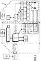
- the air traffic system 100may be used for managing the flights of one or more UAVs 102 that are controlled/operated/piloted by corresponding UAV operators 104 via associated UAV devices 106 .
- the associated UAV devices 106may be used for receiving/managing data from the UAVs 102 (e.g., telemetry, pictures, video, etc.).
- the UAVs 102may be interchangeably referred to as Unmanned Aircraft Systems (UASs) or drones throughout this description.
- UASsUnmanned Aircraft Systems
- the air traffic system 100may be divided into two logical portions: a UAV Traffic Management (UTM) system 100 A and a 3GPP system 100 B.
- UTMTraffic Management
- 3GPP3GPP system 100 B.
- the UTM system 100 Amanages flight plan information
- the 3GPP system 100 Bprovides network services to UAVs 102 and associated UAV devices 106 .
- the UAVs 102may be small or miniature UAVs, which are unmanned aircraft that are small enough to be considered portable by an average man and typically operate/cruise at altitudes lower than larger aircraft.
- a small UAVmay be any unmanned aircraft that is fifty-five pounds or lighter and/or is designed to operate below 400 feet.
- the embodiments described hereinmay be applied to small UAVs, the systems and methods are not restricted to aircraft of these sizes or that are designed to operate at particular altitudes. Instead, the methods and systems described herein may be similarly applied to aircraft of any size or design and with or without an onboard pilot/operator.
- the methods and systems described hereinmay be used for UAVs 102 larger than fifty-five pounds and/or UAVs 102 that are designed to fly above 400 feet.
- the UAVs 102are aircraft without an onboard human controller. Instead, the UAVs 102 may be operated/piloted using various degrees of autonomy.
- a UAV 102may be operated by a human (e.g., the UAV operator 104 ) located on the ground or otherwise removed and independent of the location of the UAV 102 .
- a UAV operator 104may be located on the ground and acts to directly control each movement of a UAV 102 or a group of UAVs 102 through an associated UAV device 106 (e.g., a radio controller) via one or more inputs of the associated UAV device 106 (e.g., joystick, buttons, switches, etc.).
- an associated UAV device 106e.g., a radio controller
- the UAV operator 104may transmit commands via the associated UAV device 106 to cause the UAV 102 to adjust/move particular flight instruments (e.g., flaps, blades, motors, etc.) for the purpose of following a flight plan or another set of objectives.
- the UAV operator 104may provide a flight plan to the UAV 102 .
- the UAV 102may adjust/move particular flight instruments to fulfill objectives of the flight plan.
- a human operatore.g., the UAV operator 104
- a flight planmay include one or more points of a path (e.g., a starting point, an ending point, and/or a set of waypoints, where each are defined by longitudinal and latitudinal coordinates), a set of velocities, a set of altitudes, a set of headings/directions, a set of events (e.g., capture video at prescribed times or locations, hover over an area for a specified interval, etc.), a time/expiration/duration, and a set of restricted zones/areas.
- a pathe.g., a starting point, an ending point, and/or a set of waypoints, where each are defined by longitudinal and latitudinal coordinates
- a set of velocitiese.g., a set of altitudes, a set of headings/directions
- a set of eventse.g., capture video at prescribed times or locations, hover over an area for a specified interval, etc.
- the UAV 102is to take off from location A 1 (corresponding to a first set of longitude and latitude coordinates) and travel to location A 2 (corresponding to a second set of longitude and latitude coordinates) using the path B.
- the path Bmay be separated into the segments B 1 and B 2 .
- the UAV 102is restricted to an altitude between 300 feet and 400 feet and a velocity of 100 miles/hour during segment B 1 and an altitude between 350 feet and 400 feet and a velocity of 90 miles/hour during segment B 2 .
- the above altitude and velocity limitationsare merely exemplary and in other embodiments higher altitude and velocity limitations may be assigned/issued for a UAV 102 (e.g., altitude limitations above 400 feet and velocity limitations above 100 miles/hour).
- a flight plan 300may indicate that the UAV 102 is to take off from location A 1 , travel to location A 2 , and avoid a set of restricted zones 302 A and 302 B.
- the UAV 102is directed to reach the target location A 2 without entering the set of restricted zones 302 A and 302 B.
- the restricted zonesmay be relative to geographical location (defined by a set of coordinates), an altitude, and/or a velocity.
- the UAV 102may be permitted to enter restricted zone 302 A but only at a prescribed altitude and/or only at a prescribed velocity.
- a flight plan 400may provide clearance for the UAV 102 to fly in a designated clearance zone 402 .
- the clearance zone 402may be a confined area associated with an altitude range (e.g., between 400-500 feet) and/or an expiration/duration (e.g., an expiration of 11:40 PM).
- the UAV 102may fly anywhere in the designated clearance zone 402 until the clearance has expired.
- flight plansmay be encoded/presented using any format.
- a flight planmay be represented and passed to the UAV 102 using an extensible markup language (XML) based format or another encoding or representation that is decodable and parseable by a machine.
- XMLextensible markup language
- flight plansmay be followed via a UAV operator 104 interacting with an associated UAV device 106 (e.g., a radio controller) and/or via some level of autonomy on the part of the UAV 102 .
- a portion of the 3GPP system 100 Bmay operate to control the UAV 102 independent of the associated UAV device 106 through issuance of control commands to the UAV 102 over the 3GPP system 100 B.
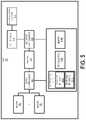
- FIG. 5shows a block diagram of a UAV 102 according to one example embodiment.
- Each element of the UAV 102will be described by way of example below and it is understood that each UAV 102 may include more or less components than those shown and described herein.
- a UAV 102may include a set of motors 502 controlled by one or more motor controllers 504 , which control the speed of rotation of the motors (e.g., rounds per minute).
- the term enginemay be used synonymously with the term motor and shall designate a machine that converts one form of energy into mechanical energy.
- the motors 502may be electrical motors that convert electricity stored in the battery 506 into mechanical energy.
- the UAV 102may include any number of motors 502 that are placed in any configuration relative to the body and/or an expected heading of the UAV 102 .
- the motors 502may be configured such that the UAV 102 is a multirotor helicopter (e.g., a quadcopter).
- the motors 502may be configured such that the UAV 102 is a fixed wing aircraft (e.g., a single engine or dual engine airplane). In these embodiments, the motors 502 , in conjunction with other elements of the UAV 102 serve to keep the UAV 102 in flight and/or propel the UAV 102 in a desired direction. In some embodiments, the UAV 102 may not include motors 502 for propelling the UAV 102 forward. In this embodiment, the UAV 102 may be a glider or lighter than air craft (e.g., a weather balloon).
- the motors 502are controlled by one or more motor controllers 504 , which govern the speed of rotation of each motor 502 .
- the motor controllers 504may work in conjunction with actuator controllers 508 and actuators 510 that control the pitch/angle/rotation of propellers, flaps, slats, slots, rotors, rotor blades/wings, and other flight control systems 514 .
- the motor controllers 504 and actuator controllers 508may be managed/controlled by one or more processors 512 A that are communicatively coupled to a memory 512 B and one or more interfaces 512 C.
- the memory 512 Bmay store instructions that when executed by the processors 512 A cause the UAV 102 , via adjustments to settings/parameters of the motor controllers 504 and actuator controllers 508 , to move in a particular direction (vertical or horizontal) or maintain a particular flight pattern (e.g., hover at a particular altitude).
- the UAV 102may communicate with one or more other devices using the one or more interfaces 512 C.
- one of the interfaces 512 C in the UAV 102may comply with a cellular protocol.
- the cellular interface 512 C 1may adhere to one or more of Global System for Mobile communication (GSM) (including General Packet Radio Service (GPRS) and Enhanced Data Rates for GSM Evolution (EDGE)), UMTS (including High Speed Packet Access (HSPA)), and Long-Term Evolution (LTE).
- GSMGlobal System for Mobile communication
- GPRSGeneral Packet Radio Service
- EDGEEnhanced Data Rates for GSM Evolution
- UMTSincluding High Speed Packet Access (HSPA)
- LTELong-Term Evolution
- one of the interfaces 512 C in a UAV 102may comply with a line-of-sight radio protocol.
- the line-of-sight interface 512 C 2may adhere to one or more line-of-sight radio protocols, including the Micro Air Vehicle Link (MAVLink) protocol that operates in a point-to-point connection with an associated UAV device 106 (e.g., a radio controller and/or a telemetry computer).
- MAVLinkMicro Air Vehicle Link
- UAV device 106e.g., a radio controller and/or a telemetry computer.
- MAVLinkMicro Air Vehicle Link
- two network elementsare entirely dependent on a clear line-of-sight between them to maintain a network connection. Obstacles or interference that prevent such line-of-sight reduces (in the case of a near line-of-sight connection) or prevents the transfer of data between the network elements.
- a cellular networkdoes not rely on the network elements maintaining a line-of-sight with each other and each network element may instead connect with any number of network devices (e.g., cells) to facilitate the transfer of data to the other network element.
- network devicese.g., cells
- cellular networkspermeate the landscape and are not constrained by a line-of-sight or a distance between network elements (i.e., cellular networks are able to provide beyond-line-of-sight communications).
- the bandwidth of a cellular connectionmay be sacrificed to provide a longer distance communication channel between a network element and a piece of infrastructure (e.g., between a UAV 102 and a cell 110 ).
- FIG. 6shows an associated UAV device 106 according to one embodiment.
- the associated UAV device 106may include one or more input devices 601 .
- the one or more input devices 601may allow a UAV operator 104 to input commands for controlling a UAV 102 (e.g., when the associated UAV device 106 is a radio controller) or for managing data received from the UAV 102 (e.g., when the associated UAV device 106 is a telemetry/media collecting computer).
- the input devices 601may include one or more of a joystick, set of up-down-left-right arrows, a mouse, a keyboard, buttons, switches, or any similar input mechanisms.
- a set of one or more analog-to-digital converters 603may convert analog signals produced by the one or more input devices 601 into digital signals for processing by one or more processors 605 A based on instructions stored on memory 605 B.
- the associated UAV devices 106may communicate with one or more other devices using the one or more interfaces 605 C.
- one of the interfaces 605 C in the associated UAV device 106may comply with a cellular protocol.
- the cellular interface 605 C 1may adhere to one or more of GSM (including GPRS and EDGE), UMTS (including HSPA), and LTE.
- one of the interfaces 605 C in the associated UAV device 106may comply with a line-of-sight radio protocol.
- the line-of-sight interface 605 C 2may adhere to one or more line-of-sight radio protocols, including the MAVLink protocol that operates in a point-to-point connection with a UAV 102 .
- the UAV 102 and the associated UAV device 106may operate in the GSM EDGE Radio Access Network (GERAN) 108 A, the Universal Terrestrial Radio Access Network (UTRAN) 108 B, and/or the Evolved Universal Mobile Telecommunications System (UMTS) Terrestrial Radio Access Network (E-UTRAN) 108 C of the 3GPP system 100 B using one or more of the interfaces 512 C and 605 C (e.g., the cellular interface 512 C 1 and the cellular interface 605 C 1 ).
- GERANGSM EDGE Radio Access Network
- UTRANUniversal Terrestrial Radio Access Network
- E-UTRANEvolved Universal Mobile Telecommunications System
- the GERAN 108 A, the UTRAN 108 B, and/or the E-UTRAN 108 Cmay be administered by a network operator (e.g., a cellular network operator) and the UAV 102 and the associated UAV device 106 may be subscribers to one or more of these networks 108 A, 108 B, and 108 C.
- a network operatore.g., a cellular network operator
- the GERAN 108 A, the UTRAN 108 B, and the E-UTRAN 108 Cmay hereinafter be individually be referred to as a wireless network 108 , a cellular network 108 , a wireless cellular network 108 , an access network 108 , or a wireless access network 108 and may be collectively referred to as wireless networks 108 , cellular networks 108 , wireless cellular networks 108 , access networks 108 , or wireless access networks 108 .
- the GERAN 108 A, the UTRAN 108 B, and/or the E-UTRAN 108 Cmay comprise various network devices.
- Each of the network devicesmay, in some embodiments, be electronic devices that can be communicatively connected to other electronic devices on the network (e.g., other network devices, user equipment devices (such as UAVs 102 and associated UAV devices 106 ), radio base stations, etc.).
- the network devicesmay include radio access features that provide wireless radio network access to other electronic devices such as user equipment devices (UEs) (for example a “radio access network device” may refer to such a network device).
- UEsuser equipment devices
- the network devicesmay be base stations, such as an enhanced NodeB (eNodeB) in Long-Term Evolution (LTE), a NodeB in Wideband Code Division Multiple Access (WCDMA), or other types of base stations, as well as a Radio Network Controller (RNC), a Base Station Controller (BSC), or other types of control nodes.
- eNodeBenhanced NodeB
- LTELong-Term Evolution
- WCDMAWideband Code Division Multiple Access
- RNCRadio Network Controller
- BSCBase Station Controller
- Each of these network devices that include radio access features to provide wireless radio network access to other electronic devicesmay be referred to as cells (e.g., the cells 110 A and 110 B), towers, cellular towers, or the like.
- each associated UAV device 106may be connected to the GERAN 108 A, the UTRAN 108 B, and/or the E-UTRAN 108 C via a corresponding connection 112 with a cell 110 .
- the associated UAV device 106 1may attach to the GERAN 108 A, the UTRAN 108 B, and/or the E-UTRAN 108 C via the connection 112 1 with one of the cells 110 A and 110 B and the associated UAV device 106 2 may attach to the GERAN 108 A, the UTRAN 108 B, and/or the E-UTRAN 108 C via the connection 112 2 with one of the cells 110 A and 110 B.
- each UAV 102may be connected to the GERAN 108 A, the UTRAN 108 B, and/or the E-UTRAN 108 C via a corresponding connection 120 with a cell 110 .
- the UAV 102 1may attach to the GERAN 108 A, the UTRAN 108 B, and/or the E-UTRAN 108 C via the connection 120 1 with one of the cells 110 A and 110 B and the UAV 102 2 may attach to the GERAN 108 A, the UTRAN 108 B, and/or the E-UTRAN 108 C via the connection 120 2 with one of the cells 110 A and 110 B.
- connections 112 and 120assist the UAVs 102 and the associated UAV devices 106 to communicate with each other.
- the UAV 102 1may communicate telemetry/video/image data via the connection 120 1 and the associated UAV device 106 1 may receive this telemetry/video/image data via the connection 112 1 .
- the associated UAV device 106 2may communicate control commands (e.g., individual commands or a flight plan) via the connection 112 2 and the UAV 102 2 may receive the control commands via the connection 120 2 .
- the UAV operator 104may maintain a connection with other elements of the UTM system 100 A.
- the UAV operator 104may maintain connection 138 with a UAS Service Supplier (USS) 124 .
- the connection 138may be a point-to-point connection while in other embodiments the connection 138 may be part of a distributed network.
- the connection 138is separate from the access networks GERAN 108 A, UTRAN 108 B, and E-UTRAN 108 C while in other embodiments the connection 138 is part of one of the access networks GERAN 108 A, UTRAN 108 B, and E-UTRAN 108 C.
- connection 138allows the UAV operator 104 to transmit data to or receive data from the USS 124 regarding a current, past, or future flight.
- the connection 138may allow the UAV operator 104 to convey to the USS 124 one or more of the following: airspace information, alarms and notifications, authentication/authorization (e.g., use of a subscriber identification module (SIM) based identity to check UAV 102 and pilot/UAV operator 104 registrations and authorizations), and reports and logs (e.g., to establish liability in case of accidents).
- SIMsubscriber identification module
- the UAV operator 104may transmit a proposed flight plan to the USS 124 via the connection 138 .
- the UTM system 100 Amay include a plurality of USSs 124 .
- the set of USSs 124may alternatively be referred to as a USS network.
- Each USS 124offers support for safe airspace operations based on information received from a set of stakeholders and other information sources.
- the USSs 124may share information about their supported operations to promote safety and to ensure that each USS 124 has a consistent view of all UAV 102 operations and thus enable the UAV 102 to stay clear of each other.
- the USSs 124may receive information from a variety of stakeholders and information sources such that the USSs 124 may determine whether a proposed flight plan is authorized to proceed.
- the Federal Aviation AssociationFAA
- FAAFederal Aviation Association
- FIMSFlight Information Management System
- the FIMS 126provides administration officials a way to issue constraints and directives to the UAV operators 104 and/or the UAV 102 via a USS 124 .
- constraints and directivesmay be based on information received from the National Airspace System (NAS) Air Traffic Management (ATM) system 128 and/or other NAS data sources 130 .
- NASNational Airspace System
- ATMAir Traffic Management
- the ATM system 128could be used to mark certain restricted areas (e.g., airports and military bases) for the UAV 102 or restrict flights over forest fire areas or other spaces which are normally permitted for the UAV 102 .
- the FIMS 126may provide impact data, which may describe effects caused by the UAV 102 to a common airspace.
- impact datamay describe effects caused by the UAV 102 to a common airspace.
- the USSs 124may receive data from supplemental data service providers 132 .
- These supplemental data service providers 132may provide various pieces of data that are used by the USSs 124 in planning and authorizing a flight plan, including terrain, weather, surveillance, and performance information.
- the supplemental data service providers 132may communicate amongst each other to insure consistency and accuracy of information.
- the supplemental data service providers 132may provide data that is presented/transmitted to UAV operators 104 via the USS 124 for the planning of a flight plan/mission.
- the USSs 124may receive constraints from public safety sources 134 . This information may limit UAV 102 missions over areas when such flights may negatively affect public safety. For example, UAV 102 missions may be limited over areas that are currently hosting events with large crowds of people.
- the public safety sources 134may provide data that is presented/transmitted to UAV operators 104 via the USS 124 for the planning of a flight plan/mission.
- the USSs 124may also make UAV 102 flight/operation information available to the public 136 .
- the USS 124may determine if a proposed flight plan is authorized in view of directives, constraints, and information received from various stakeholders/sources. After concluding that the proposed flight plan is authorized or not authorized to proceed, the USS 124 may transmit a response to the UAV operator 104 . In response to receiving an authorized flight plan, the UAV operator 104 may begin controlling the UAV 102 to effectuate the authorized flight plan or the UAV operator 104 may transmit the authorized flight plan or some set of instructions describing the objectives of the authorized flight plan to the UAV 102 . Based on inputs from the UAV operator 104 , the processor 512 A together with instructions stored in the memory 512 B may control the motor controllers 504 and/or actuators 510 to achieve the objectives of the flight plan.
- the USS 124may make use of geographical location information (e.g., the current location of the UAV 102 ). In one embodiment, this location information may be received/accessed by the UTM system 100 A from the 3GPP system 100 B.
- the 3GPP system 100 Bmay represent a service standardized by various organizations. For example, the 3GPP system 100 B may be covered under Global System for Mobile Communications (GSM) and Universal Mobile Telecommunications Service (UMTS). As described herein, the 3GPP system 100 B specifies network elements/entities, the functionalities of all elements/entities, interfaces for inter/intra element/entity communications, as well as messages used to implement positioning functionality in a network.
- GSMGlobal System for Mobile Communications
- UMTSUniversal Mobile Telecommunications Service
- the 3GPP system 100 Bmay include access to location information, such as longitude and latitude coordinates, altitude, velocity, and direction/heading of a UAV 102 .
- location informationsuch as longitude and latitude coordinates, altitude, velocity, and direction/heading of a UAV 102 .
- the location informationmay be provided at a prescribed interval (e.g., every minute), upon request, or in response to an event (e.g., a UAV 102 entering a specified area).
- the 3GPP system 100 Bmay include a radio control (RC) management service 118 that serves as a gateway for the UTM system 100 A to access the 3GPP system 100 B.
- RCradio control
- an RC client 122 of the UTM system 100 Amay access the 3GPP system 100 B via the RC management service 118 .
- the RC management service 118may facilitate connections between UAVs 102 and associated UAV devices 106 .
- the RC management service 118may determine an association based on identifiers of the UAV 102 and the associated UAV device 106 . In response to this determined association, the RC management service 118 may facilitate routing of communications between the UAV 102 and the associated UAV device 106 (e.g., control commands, telemetry data, video data, image data, etc.).
- the RC management service 118ensures that UAVs 102 communicate with appropriate associated UAV devices 106 without undue configuration by the UAV 102 and/or the associated UAV device 106 .
- the RC management service 118may utilize RC applications that run within a virtual machine for managing communications of the UAVs 102 and/or associated UAV devices 106 .
- the RC management service 118may be communicatively coupled to various support services, including a Home Subscriber Server (HSS) 116 .
- HSSHome Subscriber Server
- the HSS 116may contain or have access to a master user database that supports network access.
- the HSS 116may contain or have access to subscription-related information (subscriber profiles) for performing authentication and authorization of users (e.g., authentication of an account associated with an interface 512 C of the UAV 102 or an interface 605 C of the associated UAV device 106 ).
- the HSS 116can provide information about the subscriber's location and Internet Protocol (IP) information.
- IPInternet Protocol
- the HSS 116may function similarly to a GSM home location register (HLR) and/or an Authentication Centre (AuC).
- HLRGSM home location register
- AuCAuthentication Centre
- the UTM system 100 Amay request and receive network subscription information associated with a UAV 102 and/or an associated UAV device 106 .
- the 3GPP system 100 Bis network operator specific, the UTM system 100 A must be aware of which network operator and what account is associated with a UAV 102 and/or an associated UAV device 106 .
- the RC management service 118may send requests to various controllers 114 associated with separate access networks 108 . In response to the requests, the controllers 114 coordinate and submit responses to the RC management service 118 .
- the RC management service 118may communicate via one or more interfaces with a 2G Serving General Packet Radio Service (GPRS) Support Node (SGSN) 114 A, a 2G Mobile services Switching Centre (MSC) 114 B for a GSM EDGE Radio Access Network (GERAN) 108 A.
- GPRSGeneral Packet Radio Service
- MSC2G Mobile services Switching Centre
- GERANGSM EDGE Radio Access Network
- the 2G-SGSN 114 Amay communicate with the GERAN 108 A via the Gb interface and the 2G-MSC 114 B may communicate with the GERAN 108 A via the A interface.
- the 2G-SGSN 114 A and the 2G-MSC 114 Bmay manage charging/billing, location request management, authorization of location services, and general
- the RC management service 118may communicate via one or more interfaces with a 3G-SGSN 114 C or an MSC server 114 D for a Universal Terrestrial Radio Access Network (U IRAN) 108 B.
- the 3G-SGSN 114 C and the MSC server 114 Dmay communicate with the UTRAN 108 B via the lu interface.
- the 3G-SGSN 114 C and the MSC server 114 Dmay manage charging/billing, location request management, authorization of location services, and general operation of location services for the UTRAN 108 B.
- the RC management service 118may communicate via one or more interfaces with a Mobility Management Entity (MME) 114 E of an Evolved Universal Mobile Telecommunications System (UMTS) Terrestrial Radio Access Network (E-UTRAN) 108 C.
- MMEMobility Management Entity
- UMTSEvolved Universal Mobile Telecommunications System
- E-UTRANEvolved Universal Mobile Telecommunications System
- the MME 114 Emay communicate with the E-UTRAN 108 C via the S1 interface.
- the MME 114 Emay manage charging/billing, location request management, authorization of the location services, and general operation of location services for the E-UTRAN 108 C.
- one or more of the portions of the air traffic system 100may be implemented through virtualization.
- a cloud execution environmente.g., one or more virtual machines or containers
- the RC management service 118may be used by the RC management service 118 to manage communications between UAVs 102 and associated UAV devices 106 .
- the 3GPP system 100 Bmay also provide network services to other network devices.
- the 3GPP system 100 Bmay simultaneously provide network services to one or more UAVs 102 , one or more associated UAV devices 106 , and one or more cellular telephones.
- the systems, methods, and devices described hereinare not restricted to this type of cellular network. In other embodiments, different protocols and infrastructures may be used by the systems, methods, and devices described herein.
- the method 700facilitates use of a cellular network with UAVs 102 and associated UAV devices 106 by automatically determining associations between UAVs 102 and associated UAV devices 106 and routing communications between UAVs 102 and associated UAV devices 106 based on the determined associations.
- FIG. 7The operations in the diagram of FIG. 7 will be described with reference to the exemplary implementations of the other figures. However, it should be understood that the operations of the diagram can be performed by implementations other than those discussed with reference to the other figures, and the implementations discussed with reference to these other figures can perform operations different than those discussed with reference to the diagram. Although described and shown in FIG. 7 in a particular order, the operations of the method 700 are not restricted to this order. For example, one or more of the operations of the method 700 may be performed in a different order or in partially or fully overlapping time periods. Accordingly, the description and depiction of the method 700 is for illustrative purposes and is not intended to restrict to a particular implementation.
- Each operation of the method 700may be performed by one or more components of the air traffic system 100 .
- the operations of the method 700may be performed by one or more of the RC management service 118 , the RC client 122 , the HSS 116 , network controllers 114 (e.g., the MME 114 E), UAVs 102 , and/or associated UAV devices 106 .
- the method 700may commence at operation 702 with a determination that one or more associated UAV devices 106 are attached/connected to a wireless network 108 .
- the RC management service 118may determine that the associated UAV device 106 1 and/or the associated UAV device 106 2 are attached to the E-UTRAN 108 C at operation 702 .
- the associated UAV device 106 1may be attached to the E-UTRAN 108 C via the cell 110 A and the associated UAV device 106 2 may be attached to the E-UTRAN 108 C via the cell 110 B.
- Each of the associated UAV device 106 1 and the associated UAV device 106 2may have been attached to the E-UTRAN 108 C for any period of time prior to performance of operation 702 (e.g., seconds, minutes, hours, etc.).
- the RC management service 118may be signaled each time an associated UAV device 106 attaches to one of the access networks 108 .
- the MME 114 Emay signal the RC management service 118 each time an associated UAV device 106 attaches to the E-UTRAN 108 C.
- the RC management service 118is described as being separate from the controllers 114 , in one embodiment, the RC management service 118 or the functionality of the RC management service 118 may be integrated in or embodied by one or more of the controllers 114 (e.g., the MME 114 E). Integrating/embodying the functionality of the RC management service 118 allows the use of pre-existing interfaces and thus more efficient interoperability of the RC management service 118 in the 3GPP system 100 B.
- the method 700may determine that one or more UAVs 102 are attached/connected to a wireless network 108 .
- the RC management service 118may determine that the UAV 102 1 and/or the UAV 102 2 are attached to the E-UTRAN 108 C at operation 704 .
- the UAV 102 1may be attached to the E-UTRAN 108 C via the cell 110 A and the UAV 102 2 may be attached to the E-UTRAN 108 C via the cell 110 B.
- Each of the UAV 102 1 and the UAV 102 2may have been attached to the E-UTRAN 108 C for any period of time prior to performance of operation 704 (e.g., seconds, minutes, hours, etc.).
- the RC management service 118may be signaled each time a UAV 102 attaches to one of the access networks 108 .
- the MME 114 Emay signal the RC management service 118 each time a UAV 102 attaches to the E-UTRAN 108 C.
- operation 702may occur in a different order.
- operation 704may be performed prior to operation 702
- operations 702 and 704are performed in entirely or partially overlapping time periods.
- operations 702 and 704may be performed after being signaled by controllers 114 .
- the one or more UAVs 102 and/or the one or more associated UAV devices 106may be attached to the wireless network 108 without providing the Internet or complete network access to these devices.
- the one or more UAVs 102 and/or the one or more associated UAV devices 106are focused on communications with each other, Internet and/or complete access to the wireless network 108 and other associated networks may not be provided.
- the method 700may route, in response to determining that the one or more associated UAV devices 106 and one or more UAVs 102 are attached to the wireless network 108 , at least one of (1) communications from at least one of the one or more UAVs 102 to at least one of the one or more associated UAV devices 106 and (2) communications from at least one of the one or more associated UAV devices 106 to at least one of the one or more UAVs 102 .
- one of the one or more associated UAV devices 106is a radio controller that generates flight commands for one of the one or more UAVs 102 .
- operation 706may route the flight commands of the associated UAV device 106 to an interface (e.g., the cellular interface 512 C 1 ) of the one of the one or more UAVs 102 .
- the flight commandsare to cause the one of the one or more UAVs 102 to adjust one or more flight parameters to adjust movement of the one of the one or more UAVs 102 .
- one of the one or more associated UAV devices 106is a telemetry device/computer that consumes telemetry data produced by one of the one or more UAVs 102 .
- operation 706routes the telemetry data from an interface (e.g., the cellular interface 512 C 1 ) of the one of the one or more UAVs 102 to the one of the one or more associated UAV devices 106 .
- one or more applicationsmay be used for handling/managing communications between UAVs 102 and associated UAV devices 106 .
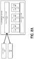
- the RC management service 118may include a cloud orchestrator 801 for configuring one or more of the RC applications 803 A- 803 C.
- the RC management service 118may be deployed in an Infrastructure as a Service (IaaS), Platform as a Service (PaaS), or Software as a Service (SaaS) private or public cloud environment that communicates with the HSS 116 and/or the UTM system 100 A (via the RC client 122 ) to authenticate and verify subscription information of UAVs 102 and associated UAV devices 106 .
- IaaSInfrastructure as a Service
- PaaSPlatform as a Service
- SaaSSoftware as a Service
- the RC management service 118may include any number of RC applications 803 .
- the cloud orchestrator 801may configure (e.g., provision, deploy, and/or start associated servers/computers; acquire and assign storage capacity; manage networking; create virtual machines; and gain access to specific software on cloud services) one or more RC applications 803 .
- the cloud platform 805may thereafter manage interactions of the RC applications 803 in corresponding virtual machines.
- Each of the RC applications 803may correspond to a different type of communications of a UAV 102 and/or an associated UAV device 106 .
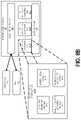
- FIG. 8Bshows an RC application 803 A according to one embodiment.
- the RC application 803 Amay include one or more of the modules 807 A- 807 D.
- Each of the modules 807 A- 807 Dmay be used for different types of communications.
- a telemetry collector module 807 Amay be used for collecting, processing, and/or managing telemetry data (e.g., velocity, acceleration, location, etc. of a UAV 102 and/or latency, signal-to-noise ratio (SNR), and/or other characteristics of the connection 120 ).
- SNRsignal-to-noise ratio
- the control proxy module 807 Bmay be used for controlling/managing a proxy connection for a UAV 102 and/or an associated UAV device 106 .
- the lawful intercept of control module 807 Cmay be used for controlling/managing commands from a law enforcement or other official when control of the UAV 102 has been transferred away from the original UAV operator 104 (e.g., the UAV operator 104 becomes a law enforcement official after the UAV 102 has entered into a restricted area (e.g., airspace of an airport or a stadium)).
- the authentication and security module 807 Dmay be used for managing/controlling authentication and security related to the connection 112 or the connection 120 (e.g., ensure communications received by a UAV 102 are from an authorized associated UAV device 106 or ensure communications received by an associated UAV device 106 are from an authorized UAV 102 ).
- each RC application 803is instantiated with a single module 807 to handle a single type of communication while in other embodiments, an RC application 803 may be instantiated with multiple modules 807 such that the RC application 803 may handle multiple types of communications.
- routing of communications at operation 706may be performed further in response to determining an association between one of the one or more associated UAV devices 106 determined to be attached to the wireless network 108 at operation 702 and one of the one or more UAVs 102 determined to be attached to the wireless network 108 at operation 704 .
- FIG. 9Ashows the UAV 102 1 connected to a wireless network 108 via the cell 110 A and the associated UAV device 106 1 connected to the wireless network 108 via the cell 110 A.
- the RC management service 118may determine whether the UAV 102 1 and the associated UAV device 106 1 are associated with each other. For instance, as shown in FIG. 9A , the associated UAV device 106 1 is a radio controller that may be used to generate and transmit flight commands. In this example, the RC management service 118 may determine an association between the associated UAV device 106 1 and the UAV 102 1 such that flight commands from the associated UAV device 106 1 may be routed to the UAV 102 1 at operation 706 .
- FIG. 9Bshows the associated UAV device 106 2 that is connected to the wireless network 108 via the cell 110 B and the UAV 102 2 that is connected to the wireless network 108 via the cell 110 A.
- the associated UAV device 106 2may be a radio controller that generates and transmits flight commands.
- the RC management service 118may determine an association between the associated UAV device 106 2 and the UAV 102 2 such that flight commands from the associated UAV device 106 2 may be routed to the UAV 102 2 at operation 706 .
- the flight commandsmay be routed/tunneled between the cells 110 A and 110 B via an interface between the cells 110 (e.g., the X2 interface when the cells 110 are eNodeBs).
- the interfaceforms a mesh network between deployed cells 110 such that the UAV 102 2 and the associated UAV device 106 2 may maintain connectivity in the entire wireless network 108 and regardless of what cells 110 are used for attachment.
- various tunneling protocols and systemsmay be used (e.g., GPRS Tunneling Protocol (GTP), Generic Routing Encapsulation (GRE), and Virtual Extensible Local Area Network (VXLAN)) to bridge communications between cells 110 in other access networks 108 and between different radio technologies (e.g., between GERAN 108 A, UTRAN 108 B, and E-UTRAN 108 C).
- GTPGPRS Tunneling Protocol
- GREGeneric Routing Encapsulation
- VXLANVirtual Extensible Local Area Network
- multiple associated UAV devices 106may be associated with a single UAV 102 .
- the associated UAV device 106 3may be connected to the wireless network 108 via the cell 110 B.
- the associated UAV device 106 3may be a telemetry computer that collects and/or manages telemetry data for a UAV 102 .
- the RC management service 118may determine an association between the associated UAV device 106 3 and the UAV 102 2 such that telemetry data generated and transmitted by the UAV 102 2 is routed to the associated UAV device 106 3 at operation 706 .
- routing communications for the examples provided in FIG. 9A , FIG. 9B , and FIG. 9Cmay be performed by instantiating RC applications 803 with corresponding modules 807 .
- routing communications for the examples provided in FIG. 9B and FIG. 9C at operation 706may be performed by sub-operations 706 A and 706 B, respectively.
- the RC application 803 Bmay be instantiated in a virtual machine for the associated UAV device 106 2 .
- the RC application 803 Bis configured to handle a first set of communications between the UAV 102 2 and the associated UAV device 106 2 . For example, as shown in FIG.
- the associated UAV device 106 2may be a radio controller and the RC application 803 B may be configured with a control proxy module 807 B to route flight commands from the associated UAV device 106 2 to the UAV 102 2 .
- the RC application 803 Cmay be instantiated in a virtual machine for the associated UAV device 106 3 .
- the RC application 803 Cis configured to handle a second set of communications between the UAV 102 2 and the associated UAV device 106 3 . For example, as shown in FIG.
- the associated UAV device 106 3may be a telemetry computer and the RC application 803 B may be configured with a telemetry collector module 807 A to route flight telemetry data from the UAV 102 2 to the associated UAV device 106 3 .
- routing of communicationsmay be performed in response to determining an association between an associated UAV device 106 and a UAV 102 .
- the RC management service 118may determine an association between an associated UAV device 106 and a UAV 102 based on queries to the HSS 116 and/or the UTM system 100 A. For example, the RC management service 118 may determine an identifier for an associated UAV device 106 1 , which was determined at operation 702 to be attached to the wireless network 108 , and an identifier for the UAV 102 1 , which was determined at operation 704 to be connected to the wireless network 108 .
- the identifiers for the associated UAV device 106 1 and/or the UAV 102 1may be based on a subscriber identification module (SIM) card installed in both devices, soft SIM cards, pre-installed public and private keys, etc.
- SIMsubscriber identification module
- the RC management service 118may query the HSS 116 and/or the UTM system 100 A to determine an association.
- an associationmay be determined based on locating an entry in a data structure with both the identifier of the associated UAV device 106 1 and the identifier of the UAV 102 1 .
- a first set of setup packetsmay be transmitted to the associated UAV device 106 and a second set of setup packets may be transmitted to the UAV 102 .
- the first set of setup packetsmay include bearer information of the UAV 102 and the second set of setup packets may include bearer information of the associated UAV device 106 .
- the RC management service 118may transmit the first and second sets of setup packets to the respective associated UAV device 106 and UAV 102 .
- transmission of setup packetsmay be performed in lieu of using the RC management service 118 to route all communications between the corresponding associated UAV device 106 and UAV 102 .
- the associated UAV device 106 and UAV 102may direct future communications directly to the UAV 102 and the associated UAV device 106 , respectively.
- the RC management service 118may detect an event associated with a UAV 102 and/or an associated UAV device 106 .
- the eventmay be (1) the UAV 102 1 entering an airspace without authorization or (2) the associated UAV device 106 1 detaching from the wireless network 108 . Either of these events may cause a situation where control of the UAV 102 1 cannot remain with the UAV operator 104 1 that is in control or is otherwise managing the associated UAV device 106 1 .
- the RC management service 118may generate one or more commands for transmission to the UAV 102 1 at operation 710 to control the UAV 102 1 and in particular to control the flight of the UAV 102 1 (e.g., flight commands that control one or more of motor(s) 502 , motor controller(s) 504 , actuator controller(s) 508 , actuator(s) 510 , and flight control system 514 ).
- the commands of operation 710may be generated for transmission in place of the commands from the associated UAV device 106 1 .
- a law enforcement officialmay need to take control of the UAV 102 1 .
- the RC management service 118may generate flight commands for the UAV 102 1 at operation 710 .
- the flight commands of operation 710may direct the UAV 102 1 away from the airspace that the UAV 102 1 does not have authorization to enter and/or to a law enforcement landing site such that a law enforcement agent may take possession of the UAV 102 1 .
- the flight commands of operation 710may direct the UAV 102 1 to a safe landing site.
- generation and or transmission of commands by a law enforcement officialmay be caused by the lawful intercept of control module 807 C of an RC application 803 .
- UAVs 102 and associated UAV devices 106may disconnect from one cell 110 in the wireless network 108 and reconnect with a different cell 110 in the wireless network 108 . This transition may require a handover procedure to be conducted.
- the UAV 102 1may attach to the cell 110 A such that corresponding bearer setup information may be passed to the RC management service 118 .
- the associated UAV device 106 1may attach to the cell 110 A such that corresponding bearer setup information may be passed to the RC management service 118 .
- a routing/control setup proceduremay be performed between (1) the UAV 102 1 and the RC management service 118 via the cell 110 A (with corresponding acknowledgement (ACK) of such setup from the UAV 102 1 ) and (2) the associated UAV device 106 1 and the RC management service 118 via the cell 110 A (with corresponding acknowledgement (ACK) of such setup from the associated UAV device 106 1 ).
- communicationsmay be routed between the UAV 102 1 and the associated UAV device 106 1 via the cell 110 A.
- the UAV 102 1may disconnect from the cell 110 A and reconnect with the wireless network 108 via the cell 110 B.
- This actionmay result in a handover being triggered such that state, bearer, and/or other information may be transferred to the cell 110 B.
- the handovermay be triggered and/or controlled by the RC management service 118 .
- the RC management service 118may maintain the UAV 102 1 continually connected with the associated UAV device 106 1 such that routing of communications is not interrupted.
- the RC management service 118may facilitate handovers between cells 110 in other access networks 108 and between different radio technologies (e.g., between GERAN 108 A, UTRAN 108 B, and E-UTRAN 108 C).
- communicationsmay be routed/tunneled between the cells 110 A and 110 B via an interface between the cells 110 A and 110 B (e.g., the X2 interface when the cells 110 A and 110 B are eNodeBs).
- an interface between the cells 110 A and 110 Be.g., the X2 interface when the cells 110 A and 110 B are eNodeBs.
- handoversmay be handled by the cells 110 themselves with reporting to the RC management service 118 .
- the method 700 and the RC management service 118may facilitate the use of a wireless cellular network 108 (e.g., the GERAN 108 A, the UTRAN 108 B, and/or the E-UTRAN 108 C) to connect UAVs 102 and associated UAV devices 106 (e.g., radio controllers and/or telemetry computers).
- a wireless cellular network 108e.g., the GERAN 108 A, the UTRAN 108 B, and/or the E-UTRAN 108 C
- UAVs 102 and associated UAV devices 106e.g., radio controllers and/or telemetry computers.
- the method 700 and the RC management service 118may be employed to intelligently route communications between UAVs 102 and associated UAV devices 106 attached to the wireless cellular network 108 .
- cellular networksprovide high bandwidth for the transmission of large volumes of data (e.g., telemetry, video, and image data and/or complex flight commands) and consistent, long-range coverage.
- datae.g., telemetry, video, and image data and/or complex flight commands
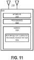
- FIG. 11illustrates a computing/networking device 1100 according to one embodiment.
- the computing/networking device 1100may include a processor 1102 communicatively coupled to a memory 1104 and an interface 1106 .
- the processor 1102may be a microprocessor, controller, microcontroller, central processing unit, digital signal processor, application specific integrated circuit, field programmable gate array, any other type of electronic circuitry, or any combination of one or more of the preceding.
- the processor 1102may comprise one or more processor cores.
- some or all of the functionality described herein as being provided by a component of the air traffic system 100may be implemented by one or more processors 1102 of one or more computing/networking devices 1100 executing software instructions, either alone or in conjunction with other computing/networking devices 1100 components, such as the memory 1104 .
- the memory 1104may store code (which is composed of software instructions and which is sometimes referred to as computer program code or a computer program) and/or data using non-transitory machine-readable (e.g., computer-readable) media 1110 , such as a non-transitory computer-readable storage medium (e.g., magnetic disks, optical disks, solid state drives, read only memory (ROM), flash memory devices, phase change memory) and machine-readable transmission media (e.g., electrical, optical, radio, acoustical or other form of propagated signals—such as carrier waves, infrared signals).
- the memory 1104may comprise non-volatile memory containing code to be executed by the processor 1102 .
- the code and/or data stored thereincan persist even when the computing/networking device 1100 is turned off (when power is removed). In some instances, while the computing/networking device 1100 is turned on, that part of the code that is to be executed by the processor(s) 1102 may be copied from non-volatile memory into volatile memory (e.g., dynamic random-access memory (DRAM), static random-access memory (SRAM)) of the computing/networking device 1100 .
- volatile memorye.g., dynamic random-access memory (DRAM), static random-access memory (SRAM)
- the interface 1106may be used in the wired and/or wireless communication of signaling and/or data to or from computing/networking device 1100 .
- interface 1106may perform any formatting, coding, or translating to allow computing/networking device 1100 to send and receive data whether over a wired and/or a wireless connection.
- the interface 1106may comprise radio circuitry capable of receiving data from other devices in the network over a wireless connection and/or sending data out to other devices via a wireless connection.
- This radio circuitrymay include transmitter(s), receiver(s), and/or transceiver(s) suitable for radiofrequency communication.
- the radio circuitrymay convert digital data into a radio signal having the appropriate parameters (e.g., frequency, timing, channel, bandwidth, etc.).
- interface 1106may comprise network interface controller(s) (NICs), also known as a network interface card, network adapter, local area network (LAN) adapter or physical network interface.
- NICsnetwork interface controller(s)
- the NIC(s)may facilitate in connecting the computing/networking device 1100 to other devices allowing them to communicate via wire through plugging in a cable to a physical port connected to a NIC.
- the processor 1102may represent part of the interface 1106 , and some or all of the functionality described as being provided by the interface 1106 may be provided in part or in whole by the processor 1102 .
Landscapes
- Engineering & Computer Science (AREA)
- Aviation & Aerospace Engineering (AREA)
- Physics & Mathematics (AREA)
- General Physics & Mathematics (AREA)
- Computer Networks & Wireless Communication (AREA)
- Signal Processing (AREA)
- Radar, Positioning & Navigation (AREA)
- Remote Sensing (AREA)
- Automation & Control Theory (AREA)
- Astronomy & Astrophysics (AREA)
- Mobile Radio Communication Systems (AREA)
Abstract
Description
Claims (17)
Applications Claiming Priority (1)
| Application Number | Priority Date | Filing Date | Title |
|---|---|---|---|
| PCT/IB2017/058525WO2019130050A1 (en) | 2017-12-29 | 2017-12-29 | Using a cellular interface for unmanned aerial vehicle communications |
Publications (2)
| Publication Number | Publication Date |
|---|---|
| US20210206490A1 US20210206490A1 (en) | 2021-07-08 |
| US11485493B2true US11485493B2 (en) | 2022-11-01 |
Family
ID=61074473
Family Applications (1)
| Application Number | Title | Priority Date | Filing Date |
|---|---|---|---|
| US16/958,325Active2038-09-08US11485493B2 (en) | 2017-12-29 | 2017-12-29 | Using a cellular interface for Unmanned Aerial Vehicle communications |
Country Status (3)
| Country | Link |
|---|---|
| US (1) | US11485493B2 (en) |
| EP (1) | EP3732927B1 (en) |
| WO (1) | WO2019130050A1 (en) |
Cited By (2)
| Publication number | Priority date | Publication date | Assignee | Title |
|---|---|---|---|---|
| US20230081924A1 (en)* | 2020-04-17 | 2023-03-16 | Telefonaktiebolaget Lm Ericsson (Publ) | A method of and an unmanned aerial vehicle for acting upon a restriction in services for the uav, a uav control server and a base station |
| US20240221509A1 (en)* | 2018-05-10 | 2024-07-04 | Beijing Xiaomi Mobile Software Co., Ltd. | Method and apparatus for reporting flight path information, and method and apparatus for determining information |
Families Citing this family (4)
| Publication number | Priority date | Publication date | Assignee | Title |
|---|---|---|---|---|
| CN111600916B (en)* | 2019-02-02 | 2022-03-25 | 华为技术有限公司 | UAV control method, device and system |
| CN110661566B (en)* | 2019-09-29 | 2021-11-19 | 南昌航空大学 | Unmanned aerial vehicle cluster networking method and system adopting depth map embedding |
| US20230284307A1 (en)* | 2022-03-04 | 2023-09-07 | At&T Intellectual Property I, L.P. | METHOD AND SYSTEM FOR FACILITATING NETWORK CONNECTIVITY FOR UNCREWED AERIAL VEHICLES (UAVs) |
| US11990046B2 (en) | 2022-05-26 | 2024-05-21 | Beta Air, Llc | Apparatus for electric aircraft communication |
Citations (78)
| Publication number | Priority date | Publication date | Assignee | Title |
|---|---|---|---|---|
| JP2003092545A (en) | 2001-09-17 | 2003-03-28 | Telecommunication Advancement Organization Of Japan | Broadcasting system using stratospheric platform |
| US20040156399A1 (en) | 2002-08-07 | 2004-08-12 | Extricom Ltd. | Wireless LAN control over a wired network |
| US20070284474A1 (en) | 2006-06-09 | 2007-12-13 | The Insitu Group, Inc. | Wirelessly controlling unmanned aircraft and accessing associated surveillance data |
| US20100062774A1 (en) | 2007-03-19 | 2010-03-11 | Ntt Docomo, Inc. | Handover method and radio base station |
| US20100085236A1 (en) | 2008-10-07 | 2010-04-08 | Honeywell International Inc. | Transponder-based beacon transmitter for see and avoid of unmanned aerial vehicles |
| US20100153001A1 (en) | 2008-12-17 | 2010-06-17 | Frederic Bauchot | Generating optimal itineraries based on network connectivity |
| CN101836478A (en) | 2007-10-26 | 2010-09-15 | 华为技术有限公司 | Mobile terminal, network entity and related method thereof |
| US20100254346A1 (en) | 2009-04-06 | 2010-10-07 | Robert Bosch Gmbh | Method for performing proactive wireless communication handoffs using a mobile client's route information |
| US7813326B1 (en) | 2005-05-27 | 2010-10-12 | Bluetronix Inc. | Swarm location service for mobile ad hoc network communications |
| WO2011100535A1 (en) | 2010-02-12 | 2011-08-18 | Apple Inc. | Augmented reality maps |
| WO2012112097A1 (en) | 2011-02-18 | 2012-08-23 | Telefonaktiebolaget L M Ericsson (Publ) | Methods and devices for providing guaranteed quality of service |
| US20120225675A1 (en) | 2009-10-02 | 2012-09-06 | Ntt Docomo, Inc. | Mobile communication method, mobile management node, and mobile station |
| US20130233964A1 (en)* | 2012-03-07 | 2013-09-12 | Aurora Flight Sciences Corporation | Tethered aerial system for data gathering |
| CN104053195A (en) | 2014-06-30 | 2014-09-17 | 京信通信系统(中国)有限公司 | A method and device for determining blacklist list members |
| US20150038140A1 (en) | 2013-07-31 | 2015-02-05 | Qualcomm Incorporated | Predictive mobility in cellular networks |
| US20150119043A1 (en) | 2013-10-31 | 2015-04-30 | Qualcomm Incorporated | Pruning target inter-radio access technology (irat) handover candidate cells |
| US20150208300A1 (en) | 2014-01-20 | 2015-07-23 | Eden Rock Communications, Llc | Dynamic automated neighbor list management in self-optimizing network |
| WO2015114572A1 (en) | 2014-01-31 | 2015-08-06 | Tata Consultancy Services Limited | A computer implemented system and method for providing robust communication links to unmanned aerial vehicles |
| US20150312813A1 (en) | 2014-04-29 | 2015-10-29 | Samsung Electronics Co., Ltd. | Method and apparatus for transmitting a handover report and an rlf report |
| WO2015179439A1 (en) | 2014-05-19 | 2015-11-26 | EpiSys Science, Inc. | Method and apparatus for control of multiple autonomous mobile nodes based on dynamic situational awareness data |
| US20160065345A1 (en) | 2013-04-05 | 2016-03-03 | Lg Electronics Inc. | Method for transmitting uplink control information in wireless access system and apparatus therefor |
| US20160070265A1 (en) | 2014-09-05 | 2016-03-10 | SZ DJI Technology Co., Ltd | Multi-sensor environmental mapping |
| US20160125740A1 (en) | 2014-05-20 | 2016-05-05 | Verizon Patent And Licensing Inc. | Unmanned aerial vehicle identity and capability verification |
| US20160142944A1 (en) | 2014-11-14 | 2016-05-19 | Parallel Wireless, Inc. | Seamless Mobile Handover |
| US20160142994A1 (en) | 2014-11-17 | 2016-05-19 | Qualcomm Incorporated | Techniques for transmitting synchronization signals in a shared radio frequency spectrum band |
| US20160140851A1 (en) | 2014-11-18 | 2016-05-19 | Ziv LEVY | Systems and methods for drone navigation |
| US9363690B1 (en) | 2015-07-10 | 2016-06-07 | Cisco Technology, Inc. | Closed-loop optimization of a wireless network using an autonomous vehicle |
| EP3029996A1 (en) | 2014-12-01 | 2016-06-08 | Tata Consultancy Services Limited | Target cell selection during handover |
| US20160161258A1 (en) | 2014-12-09 | 2016-06-09 | Sikorsky Aircraft Corporation | Unmanned aerial vehicle control handover planning |
| CN105828345A (en) | 2016-05-06 | 2016-08-03 | 华南农业大学 | Ground-air wireless sensor network communication device and method compatible with UAV |
| US9412278B1 (en) | 2015-03-31 | 2016-08-09 | SZ DJI Technology Co., Ltd | Authentication systems and methods for generating flight regulations |
| RU2595642C1 (en) | 2012-09-29 | 2016-08-27 | Хуавей Текнолоджиз Ко., Лтд. | Method of sending control information, receiving method and device |
| US20160266579A1 (en) | 2015-03-12 | 2016-09-15 | Nightingale Intelligent Systems | Automated drone systems |
| US20160284221A1 (en) | 2013-05-08 | 2016-09-29 | Matternet, Inc. | Route planning for unmanned aerial vehicles |
| US9467922B1 (en) | 2015-06-15 | 2016-10-11 | Amazon Technologies, Inc. | Cellular connections between user equipment and wireless stations based on user equipment location and wireless station locations |
| US20160300493A1 (en) | 2014-05-20 | 2016-10-13 | Verizon Patent And Licensing Inc. | Selection of networks for communicating with unmanned aerial vehicles |
| US20160300495A1 (en) | 2014-05-20 | 2016-10-13 | Verizon Patent And Licensing Inc. | Secure communications with unmanned aerial vehicles |
| WO2016161637A1 (en) | 2015-04-10 | 2016-10-13 | SZ DJI Technology Co., Ltd. | Method, apparatus and system of providing communication coverage to an unmanned aerial vehicle |
| WO2016164892A1 (en) | 2015-04-10 | 2016-10-13 | The Board Of Regents Of The Nevada System Of Higher Education On Behalf Of The University Of Nevada, Las Vegas | Methods and systems for unmanned aircraft system (uas) traffic management |
| WO2016190793A1 (en) | 2015-12-14 | 2016-12-01 | Telefonaktiebolaget Lm Ericsson (Publ) | Adjustment of planned movement based on radio network conditions |
| US20160358187A1 (en) | 2015-06-04 | 2016-12-08 | Chronicled, Inc. | Open registry for identity of things including social record feature |
| US20160363929A1 (en)* | 2015-06-10 | 2016-12-15 | Kespry, Inc | Aerial vehicle data communication system |
| US20160371985A1 (en) | 2015-06-16 | 2016-12-22 | Verizon Patent And Licensing Inc. | Dynamic navigation of uavs using three dimensional network coverage information |
| US20160371987A1 (en)* | 2015-06-17 | 2016-12-22 | Verizon Patent And Licensing Inc. | Command and control interface for uavs communication through a mobile wireless network |
| US20160380692A1 (en) | 2015-05-13 | 2016-12-29 | Ubiqomm Llc | Ground terminal and uav beam pointing in an unmanned aerial vehicle (uav) for network access |
| US9537561B1 (en) | 2016-01-21 | 2017-01-03 | Verizon Patent And Licensing Inc. | Optimization of communications with UAVS using terrestrial cellular networks |
| US20170023939A1 (en) | 2015-05-06 | 2017-01-26 | Joel David Krouse | System and Method for Controlling an Unmanned Aerial Vehicle over a Cellular Network |
| US20170045884A1 (en)* | 2015-08-10 | 2017-02-16 | Edward Kablaoui | System and Method for Drone Connectivity and Communication Over a Cellular Network |
| US9588516B1 (en) | 2016-02-08 | 2017-03-07 | Unmanned Innovation Inc. | Unmanned aerial vehicle visual line of sight control |
| EP3139516A1 (en) | 2015-09-03 | 2017-03-08 | BAE Systems PLC | Apparatus and method for communications management in an uav |
| WO2017042403A1 (en) | 2015-09-09 | 2017-03-16 | Tecteco Security Systems, S.L. | Secure control of unmanned vehicles |
| WO2017048363A1 (en) | 2015-09-18 | 2017-03-23 | Moog Inc. | Cellular aerial vehicle traffic control system and method |
| US9609288B1 (en) | 2015-12-31 | 2017-03-28 | Unmanned Innovation, Inc. | Unmanned aerial vehicle rooftop inspection system |
| US20170092137A1 (en) | 2015-09-29 | 2017-03-30 | Airbus Defence and Space GmbH | Unmanned aerial vehicle and method for safely landing an unmanned aerial vehicle |
| US20170124884A1 (en) | 2015-11-02 | 2017-05-04 | At&T Intellectual Property I, L.P. | Intelligent Drone Traffic Management Via Radio Access Network |
| US20170142766A1 (en) | 2015-11-17 | 2017-05-18 | Electronics And Telecommunications Research Institute | Method and apparatus for controlling access of terminal equipment in wireless communication system |
| US20170150373A1 (en) | 2015-11-24 | 2017-05-25 | Verizon Patent And Licensing Inc. | Adaptive antenna operation for uavs using terrestrial cellular networks |
| US9709409B2 (en) | 2012-08-31 | 2017-07-18 | Apple Inc. | Navigation system acquisition and use of cellular coverage map data |
| WO2017149160A1 (en) | 2016-03-04 | 2017-09-08 | Unifly N.V. | Very low level operations coordination platform |
| RU2637838C2 (en) | 2015-10-30 | 2017-12-07 | Сяоми Инк. | Method to control unmanned air vehicle and device for it |
| US20180086483A1 (en) | 2016-06-10 | 2018-03-29 | ETAK Systems, LLC | Elevator or tube lift for drone takeoff and control thereof via air traffic control systems |
| US20180152510A1 (en) | 2016-11-29 | 2018-05-31 | Level 3 Communications, Llc | Cross-cluster direct server return in a content delivery network (cdn) |
| US20180247544A1 (en) | 2017-02-24 | 2018-08-30 | At&T Mobility Ii Llc | Flight plan implementation, generation, and management for aerial devices |
| US20180279348A1 (en) | 2017-03-24 | 2018-09-27 | Qualcomm Incorporated | Opportunistic uplink transmission |
| US20190013923A1 (en)* | 2017-07-10 | 2019-01-10 | Realtek Semiconductor Corp. | Wireless communication device and control method |
| US20190012923A1 (en) | 2017-07-07 | 2019-01-10 | Verizon Patent And Licensing Inc. | Aerial radio frequency (rf) management |
| US20190087576A1 (en) | 2016-04-14 | 2019-03-21 | Rhombus Systems Group, Inc. | System for verification of integrity of unmanned aerial vehicles |
| US20190088156A1 (en)* | 2017-08-25 | 2019-03-21 | Aurora Flight Sciences Corporation | Virtual Reality System for Aerial Vehicle |
| US20190112048A1 (en)* | 2016-03-30 | 2019-04-18 | Matthew CULVER | Systems and methods for unmanned aerial vehicles |
| US20190289505A1 (en) | 2017-03-23 | 2019-09-19 | Fraunhofer-Gesellschaft Zur Foerderung Der Angewandten Forschung E.V. | Preemptive Handover Preparation and Tracking/Paging Area Handling and Intelligent Route Selection in a Cellular Network |
| US20190364492A1 (en) | 2016-12-30 | 2019-11-28 | Intel Corporation | Methods and devices for radio communications |
| US20200005651A1 (en) | 2016-06-10 | 2020-01-02 | ETAK Systems, LLC | Apparatus for controlling unmanned aerial vehicles and passenger drones via an air traffic control system |
| US20200100187A1 (en)* | 2017-03-23 | 2020-03-26 | Interdigital Patent Holdings, Inc. | Altitude path-loss based power control for aerial vehicles |
| US20200105149A1 (en) | 2017-03-31 | 2020-04-02 | Telefonaktiebolaget Lm Ericsson (Publ) | Enhanced flight plan for unmanned traffic aircraft systems |
| US20200225684A1 (en)* | 2016-03-24 | 2020-07-16 | Flir Detection, Inc. | Persistent aerial communication and control system |
| US20210129982A1 (en)* | 2018-05-23 | 2021-05-06 | Planck Aerosystems Inc. | System and method for drone tethering |
| US20210274311A1 (en)* | 2017-03-31 | 2021-09-02 | Telefonaktiebolaget Lm Ericsson (Publ) | Methods and systems for using network location services in a unmanned aircraft systems traffic management framework |
| US20210314081A1 (en)* | 2017-10-11 | 2021-10-07 | Genghiscomm Holdings, LLC | Detection, Analysis, and Countermeasures for Radio Transceivers |
- 2017
- 2017-12-29USUS16/958,325patent/US11485493B2/enactiveActive
- 2017-12-29WOPCT/IB2017/058525patent/WO2019130050A1/ennot_activeCeased
- 2017-12-29EPEP17835944.4Apatent/EP3732927B1/enactiveActive
Patent Citations (84)
| Publication number | Priority date | Publication date | Assignee | Title |
|---|---|---|---|---|
| JP2003092545A (en) | 2001-09-17 | 2003-03-28 | Telecommunication Advancement Organization Of Japan | Broadcasting system using stratospheric platform |
| US20040156399A1 (en) | 2002-08-07 | 2004-08-12 | Extricom Ltd. | Wireless LAN control over a wired network |
| US7813326B1 (en) | 2005-05-27 | 2010-10-12 | Bluetronix Inc. | Swarm location service for mobile ad hoc network communications |
| US20070284474A1 (en) | 2006-06-09 | 2007-12-13 | The Insitu Group, Inc. | Wirelessly controlling unmanned aircraft and accessing associated surveillance data |
| US20100062774A1 (en) | 2007-03-19 | 2010-03-11 | Ntt Docomo, Inc. | Handover method and radio base station |
| CN101836478A (en) | 2007-10-26 | 2010-09-15 | 华为技术有限公司 | Mobile terminal, network entity and related method thereof |
| US20100085236A1 (en) | 2008-10-07 | 2010-04-08 | Honeywell International Inc. | Transponder-based beacon transmitter for see and avoid of unmanned aerial vehicles |
| EP2175290A1 (en) | 2008-10-07 | 2010-04-14 | Honeywell International | Transponder-based beacon transmitter for see and avoid of unmanned aerial vehicles |
| US20100153001A1 (en) | 2008-12-17 | 2010-06-17 | Frederic Bauchot | Generating optimal itineraries based on network connectivity |
| US20100254346A1 (en) | 2009-04-06 | 2010-10-07 | Robert Bosch Gmbh | Method for performing proactive wireless communication handoffs using a mobile client's route information |
| US20120225675A1 (en) | 2009-10-02 | 2012-09-06 | Ntt Docomo, Inc. | Mobile communication method, mobile management node, and mobile station |
| WO2011100535A1 (en) | 2010-02-12 | 2011-08-18 | Apple Inc. | Augmented reality maps |
| WO2012112097A1 (en) | 2011-02-18 | 2012-08-23 | Telefonaktiebolaget L M Ericsson (Publ) | Methods and devices for providing guaranteed quality of service |
| US20130233964A1 (en)* | 2012-03-07 | 2013-09-12 | Aurora Flight Sciences Corporation | Tethered aerial system for data gathering |
| US9709409B2 (en) | 2012-08-31 | 2017-07-18 | Apple Inc. | Navigation system acquisition and use of cellular coverage map data |
| RU2595642C1 (en) | 2012-09-29 | 2016-08-27 | Хуавей Текнолоджиз Ко., Лтд. | Method of sending control information, receiving method and device |
| US20160065345A1 (en) | 2013-04-05 | 2016-03-03 | Lg Electronics Inc. | Method for transmitting uplink control information in wireless access system and apparatus therefor |
| US20160284221A1 (en) | 2013-05-08 | 2016-09-29 | Matternet, Inc. | Route planning for unmanned aerial vehicles |
| US20150038140A1 (en) | 2013-07-31 | 2015-02-05 | Qualcomm Incorporated | Predictive mobility in cellular networks |
| US20150119043A1 (en) | 2013-10-31 | 2015-04-30 | Qualcomm Incorporated | Pruning target inter-radio access technology (irat) handover candidate cells |
| US20150208300A1 (en) | 2014-01-20 | 2015-07-23 | Eden Rock Communications, Llc | Dynamic automated neighbor list management in self-optimizing network |
| WO2015114572A1 (en) | 2014-01-31 | 2015-08-06 | Tata Consultancy Services Limited | A computer implemented system and method for providing robust communication links to unmanned aerial vehicles |
| US20150312813A1 (en) | 2014-04-29 | 2015-10-29 | Samsung Electronics Co., Ltd. | Method and apparatus for transmitting a handover report and an rlf report |
| WO2015179439A1 (en) | 2014-05-19 | 2015-11-26 | EpiSys Science, Inc. | Method and apparatus for control of multiple autonomous mobile nodes based on dynamic situational awareness data |
| US20160125740A1 (en) | 2014-05-20 | 2016-05-05 | Verizon Patent And Licensing Inc. | Unmanned aerial vehicle identity and capability verification |
| US20160300495A1 (en) | 2014-05-20 | 2016-10-13 | Verizon Patent And Licensing Inc. | Secure communications with unmanned aerial vehicles |
| US20160300493A1 (en) | 2014-05-20 | 2016-10-13 | Verizon Patent And Licensing Inc. | Selection of networks for communicating with unmanned aerial vehicles |
| CN104053195A (en) | 2014-06-30 | 2014-09-17 | 京信通信系统(中国)有限公司 | A method and device for determining blacklist list members |
| US20160070265A1 (en) | 2014-09-05 | 2016-03-10 | SZ DJI Technology Co., Ltd | Multi-sensor environmental mapping |
| US20160142944A1 (en) | 2014-11-14 | 2016-05-19 | Parallel Wireless, Inc. | Seamless Mobile Handover |
| US20160142994A1 (en) | 2014-11-17 | 2016-05-19 | Qualcomm Incorporated | Techniques for transmitting synchronization signals in a shared radio frequency spectrum band |
| US20160140851A1 (en) | 2014-11-18 | 2016-05-19 | Ziv LEVY | Systems and methods for drone navigation |
| EP3029996A1 (en) | 2014-12-01 | 2016-06-08 | Tata Consultancy Services Limited | Target cell selection during handover |
| US20160161258A1 (en) | 2014-12-09 | 2016-06-09 | Sikorsky Aircraft Corporation | Unmanned aerial vehicle control handover planning |
| US20160266579A1 (en) | 2015-03-12 | 2016-09-15 | Nightingale Intelligent Systems | Automated drone systems |
| US9412278B1 (en) | 2015-03-31 | 2016-08-09 | SZ DJI Technology Co., Ltd | Authentication systems and methods for generating flight regulations |
| US20160292403A1 (en) | 2015-03-31 | 2016-10-06 | SZ DJI Technology Co., Ltd | Authentication systems and methods for generating flight regulations |
| WO2016154949A1 (en) | 2015-03-31 | 2016-10-06 | SZ DJI Technology Co., Ltd. | Authentication systems and methods for generating flight regulations |
| WO2016161637A1 (en) | 2015-04-10 | 2016-10-13 | SZ DJI Technology Co., Ltd. | Method, apparatus and system of providing communication coverage to an unmanned aerial vehicle |
| WO2016164892A1 (en) | 2015-04-10 | 2016-10-13 | The Board Of Regents Of The Nevada System Of Higher Education On Behalf Of The University Of Nevada, Las Vegas | Methods and systems for unmanned aircraft system (uas) traffic management |
| US20170023939A1 (en) | 2015-05-06 | 2017-01-26 | Joel David Krouse | System and Method for Controlling an Unmanned Aerial Vehicle over a Cellular Network |
| US20160380692A1 (en) | 2015-05-13 | 2016-12-29 | Ubiqomm Llc | Ground terminal and uav beam pointing in an unmanned aerial vehicle (uav) for network access |
| US20160358187A1 (en) | 2015-06-04 | 2016-12-08 | Chronicled, Inc. | Open registry for identity of things including social record feature |
| US20160363929A1 (en)* | 2015-06-10 | 2016-12-15 | Kespry, Inc | Aerial vehicle data communication system |
| US9467922B1 (en) | 2015-06-15 | 2016-10-11 | Amazon Technologies, Inc. | Cellular connections between user equipment and wireless stations based on user equipment location and wireless station locations |
| US20160371985A1 (en) | 2015-06-16 | 2016-12-22 | Verizon Patent And Licensing Inc. | Dynamic navigation of uavs using three dimensional network coverage information |
| US20160371987A1 (en)* | 2015-06-17 | 2016-12-22 | Verizon Patent And Licensing Inc. | Command and control interface for uavs communication through a mobile wireless network |
| US9363690B1 (en) | 2015-07-10 | 2016-06-07 | Cisco Technology, Inc. | Closed-loop optimization of a wireless network using an autonomous vehicle |
| US20170045884A1 (en)* | 2015-08-10 | 2017-02-16 | Edward Kablaoui | System and Method for Drone Connectivity and Communication Over a Cellular Network |
| EP3139516A1 (en) | 2015-09-03 | 2017-03-08 | BAE Systems PLC | Apparatus and method for communications management in an uav |
| EP3349085A1 (en) | 2015-09-09 | 2018-07-18 | Tecteco Security Systems, S.L. | Secure control of unmanned vehicles |
| WO2017042403A1 (en) | 2015-09-09 | 2017-03-16 | Tecteco Security Systems, S.L. | Secure control of unmanned vehicles |
| WO2017048363A1 (en) | 2015-09-18 | 2017-03-23 | Moog Inc. | Cellular aerial vehicle traffic control system and method |
| US20170092137A1 (en) | 2015-09-29 | 2017-03-30 | Airbus Defence and Space GmbH | Unmanned aerial vehicle and method for safely landing an unmanned aerial vehicle |
| RU2637838C2 (en) | 2015-10-30 | 2017-12-07 | Сяоми Инк. | Method to control unmanned air vehicle and device for it |
| US20170124884A1 (en) | 2015-11-02 | 2017-05-04 | At&T Intellectual Property I, L.P. | Intelligent Drone Traffic Management Via Radio Access Network |
| US20170142766A1 (en) | 2015-11-17 | 2017-05-18 | Electronics And Telecommunications Research Institute | Method and apparatus for controlling access of terminal equipment in wireless communication system |
| US20170150373A1 (en) | 2015-11-24 | 2017-05-25 | Verizon Patent And Licensing Inc. | Adaptive antenna operation for uavs using terrestrial cellular networks |
| US20170168480A1 (en) | 2015-12-14 | 2017-06-15 | Telefonaktiebolaget Lm Ericsson (Publ) | Adjustment of planned movement based on radio network conditions |
| WO2016190793A1 (en) | 2015-12-14 | 2016-12-01 | Telefonaktiebolaget Lm Ericsson (Publ) | Adjustment of planned movement based on radio network conditions |
| US9609288B1 (en) | 2015-12-31 | 2017-03-28 | Unmanned Innovation, Inc. | Unmanned aerial vehicle rooftop inspection system |
| US9537561B1 (en) | 2016-01-21 | 2017-01-03 | Verizon Patent And Licensing Inc. | Optimization of communications with UAVS using terrestrial cellular networks |
| US9588516B1 (en) | 2016-02-08 | 2017-03-07 | Unmanned Innovation Inc. | Unmanned aerial vehicle visual line of sight control |
| WO2017149160A1 (en) | 2016-03-04 | 2017-09-08 | Unifly N.V. | Very low level operations coordination platform |
| US20200225684A1 (en)* | 2016-03-24 | 2020-07-16 | Flir Detection, Inc. | Persistent aerial communication and control system |
| US20190112048A1 (en)* | 2016-03-30 | 2019-04-18 | Matthew CULVER | Systems and methods for unmanned aerial vehicles |
| US20190087576A1 (en) | 2016-04-14 | 2019-03-21 | Rhombus Systems Group, Inc. | System for verification of integrity of unmanned aerial vehicles |
| CN105828345A (en) | 2016-05-06 | 2016-08-03 | 华南农业大学 | Ground-air wireless sensor network communication device and method compatible with UAV |
| US20200005651A1 (en) | 2016-06-10 | 2020-01-02 | ETAK Systems, LLC | Apparatus for controlling unmanned aerial vehicles and passenger drones via an air traffic control system |
| US20180086483A1 (en) | 2016-06-10 | 2018-03-29 | ETAK Systems, LLC | Elevator or tube lift for drone takeoff and control thereof via air traffic control systems |
| US20180152510A1 (en) | 2016-11-29 | 2018-05-31 | Level 3 Communications, Llc | Cross-cluster direct server return in a content delivery network (cdn) |
| US20190364492A1 (en) | 2016-12-30 | 2019-11-28 | Intel Corporation | Methods and devices for radio communications |
| US20180247544A1 (en) | 2017-02-24 | 2018-08-30 | At&T Mobility Ii Llc | Flight plan implementation, generation, and management for aerial devices |
| US20200100187A1 (en)* | 2017-03-23 | 2020-03-26 | Interdigital Patent Holdings, Inc. | Altitude path-loss based power control for aerial vehicles |
| US20190289505A1 (en) | 2017-03-23 | 2019-09-19 | Fraunhofer-Gesellschaft Zur Foerderung Der Angewandten Forschung E.V. | Preemptive Handover Preparation and Tracking/Paging Area Handling and Intelligent Route Selection in a Cellular Network |
| US20180279348A1 (en) | 2017-03-24 | 2018-09-27 | Qualcomm Incorporated | Opportunistic uplink transmission |
| US20200105149A1 (en) | 2017-03-31 | 2020-04-02 | Telefonaktiebolaget Lm Ericsson (Publ) | Enhanced flight plan for unmanned traffic aircraft systems |
| US20200193844A1 (en) | 2017-03-31 | 2020-06-18 | Telefonaktiebolaget Lm Ericsson (Publ) | Enhanced flight plan for unmanned traffic aircraft systems |
| US20210274311A1 (en)* | 2017-03-31 | 2021-09-02 | Telefonaktiebolaget Lm Ericsson (Publ) | Methods and systems for using network location services in a unmanned aircraft systems traffic management framework |
| US20190012923A1 (en) | 2017-07-07 | 2019-01-10 | Verizon Patent And Licensing Inc. | Aerial radio frequency (rf) management |
| US20190013923A1 (en)* | 2017-07-10 | 2019-01-10 | Realtek Semiconductor Corp. | Wireless communication device and control method |
| US20190088156A1 (en)* | 2017-08-25 | 2019-03-21 | Aurora Flight Sciences Corporation | Virtual Reality System for Aerial Vehicle |
| US20210314081A1 (en)* | 2017-10-11 | 2021-10-07 | Genghiscomm Holdings, LLC | Detection, Analysis, and Countermeasures for Radio Transceivers |
| US20210129982A1 (en)* | 2018-05-23 | 2021-05-06 | Planck Aerosystems Inc. | System and method for drone tethering |
Non-Patent Citations (31)
| Title |
|---|
| 3GPP TS 23.203 V12.6.0, 3rd Generation Partnership Project, Technical Specification Group Services and System Aspects, Policy and charging control architecture, (Release 12), Sep. 2014, 220 pages. |
| 3GPP TS 23.203 V14.2.0, 3rd Generation Partnership Project, Technical Specification Group Services and System Aspects, Policy and charging control architecture, (Release 14), Dec. 2016, 256 pages. |
| 3GPP TS 23.271 V14.0.0, "3rd Generation Partnership Project, Technical Specification Group Services and System Aspects, Functional stage 2 description of Location Services (LCS)", (Release 14), Dec. 2016, 180 pages. |
| 3GPP TS 23.401 V14.2.0, 3rd Generation Partnership Project, Technical Specification Group Services and System Aspects, General Packet Radio Service (GPRS) enhancements for Evolved Universal Terrestrial Radio Access Network (E-UTRAN) access, (Release 14), Dec. 2016, 385 pages. |
| 3GPP TS 36.201 V14.0.0, "3rd Generation Partnership Project, Technical Specification Group Radio Access Network, Evolved Universal Terrestrial Radio Access (E-UTRA) LTE physical layer; General description", (Release 14), Sep. 2016, 15 pages. |
| 3GPP TS 36.300 V14.1.0, 3rd Generation Partnership Project, Technical Specification Group Radio Access Network, Evolved Universal Terrestrial Radio Access (E-UTRA) and Evolved Universal Terrestrial Radio Access Network (E-UTRAN), Overall description, Stage 2, (Release 14), Dec. 2016, 317 pages. |
| 3GPP TS 45.002 V14.0.0, "3rd Generation Partnership Project, Technical Specification Group Radio Access Network, GSM/Edge Multiplexing and multiple access on the radio path", (Release 14), Dec. 2016, 142 pages. |
| Aerodynamics, Beginners' Guide: Radio Control, available online at <https://rcplanes.online/guide1.htm>, May 8, 2019, 9 pages. |
| Curran et al., "Location Based Predictive Handoff Algorithm for Mobile Networks," Advances in Intelligent IT: Active Media Technology, May 2006, pp. 86-91. |
| Federal Aviation Administration, "Automatic Dependent Surveillance-Broadcast (ADS-B)", Mar. 12, 2019, 2 pages. |
| Forsberg, Fredrik, "Providing Air Traffic Control Services for Small Unmanned Aircraft Through LTE", Oct. 28, 2016, 90 pages. |
| GPS World, "uAvionix demonstrates dime-sized ADS-B for high-traffic drone operations", available online at <http://gpsworld.com/uavionix-demonstrates-dime-sized-ads-b-for-high-traffic-drone-operations>, retrieved on Apr. 4, 2017, 6 pages. |
| Guterres et al., "ADS-B Surveillance System Performance with Small UAS at Low Altitudes", American Institute of Aeronautics and Astronautics, 2017, pp. 1-15. |
| Huawei et al., "Mobility enhancement for Drones", 3GPP, Meeting #98, R2-1704997, May 15-19, 2017, 6 pages. |
| Huawei et al., "Potential enhancements for drones", 3GPP, Meeting #89, R1-1707016, May 15-19, 2017, 4 pages. |
| IEEE Standard for Information technology, "Part 11: Wireless LAN Medium Access Control (MAC) and Physical Layer (PHY) Specifications", IEEE Computer Society, Mar. 2012, 2793 pages. |
| Kapellaki et al., "The "Le" interface: performance evaluation of 2-tier and 3-tier 3GPP compliant realizations," IEEE International Conference on Communications, ICC 2005, vol. 3, No. 16, 2005, pp. 1423-1427. |
| KDDI Corporation, "Field measurement results for drone LTE enhancement", Meeting 88bis, R1-1705823, Apr. 3-7, 2017, 6 pages. |
| Latas, "The Drone Safety Platform", available online at <http://www.flylatas.com/>, retrieved on Mar. 31, 2017, 7 pages. |
| LG Electronics Inc., "Aerial Traffic Handling using Positioning Identification", 3GPP, Meeting #98, R2-1705660, May 15-19, 2017, 2 pages. |
| Mavlink, "Mavlink Common Message set specifications", available online at <http://mavlink.org/messages/common>, retrieved on Jan. 31, 2017, 98 pages. |
| Opensignal, "Opensignal combines real-world measurements with scientific analysis to provide independent insights on mobile connectivity globally", available online at <https://www.opensignal.com/>, 2020, 4 pages. |
| Orefice, "ADS-B Based Sense and Avoid Applications for General Aviation/Unmanned Aircraft", 2015, 114 pages. |
| Qualcomm, LTE Unmanned Aircraft Systems, Qualcomm Technologies, Inc., Trial Report, v1.0.1, May 12, 2017, 65 pages. |
| Ruano et al., "Augmented Reality Tool for the Situational Awareness Improvement of UAV Operators", Sensors, vol. 17, 2017, 16 pages. |
| SUR.ET1.ST05.2000-STD-12-01, Eurocontrol Standard Document for Surveillance Data Exchange, Part 12: Category 021, ADS-B Reports, Dec. 2010, 72 pages. |
| UAS Identification and Tracking (UAS ID) Aviation Rulemaking Committee (ARC), ARC Recommendations Final Report, Sep. 30, 2017, 213 pages. |
| UAvionix, "ADS-B Transceivers, Receivers and Navigation Systems for Drones", available online at <http://www.unmannedsystemstechnology.com/company/uavionix-corporation>, retrieved on Apr. 4, 2017, 10 pages. |
| Unmanned Aircraft System (UAS) Traffic Management (UTM), available online at <https://utm.arc.nasa.gov/index.shtml>, retrieved on Apr. 4, 2017, 2 pages. |
| Wikipedia, "Blockchain", available online at <https://en.wikipedia.org/w/index.php?title=Blockchain&oldid=901056350>, retrieved on Jun. 9, 2019, 20 pages. |
| Wikipedia, "Global Positioning System", available online at <https://en.wikipedia.org/w/index.php?title=Global_Positioning_ System&oldid=917890871>, Sep. 26, 2019, 21 pages. |
Cited By (3)
| Publication number | Priority date | Publication date | Assignee | Title |
|---|---|---|---|---|
| US20240221509A1 (en)* | 2018-05-10 | 2024-07-04 | Beijing Xiaomi Mobile Software Co., Ltd. | Method and apparatus for reporting flight path information, and method and apparatus for determining information |
| US12367778B2 (en)* | 2018-05-10 | 2025-07-22 | Beijing Xiaomi Mobile Software Co., Ltd. | Method and apparatus for reporting flight path information, and method and apparatus for determining information |
| US20230081924A1 (en)* | 2020-04-17 | 2023-03-16 | Telefonaktiebolaget Lm Ericsson (Publ) | A method of and an unmanned aerial vehicle for acting upon a restriction in services for the uav, a uav control server and a base station |
Also Published As
| Publication number | Publication date |
|---|---|
| US20210206490A1 (en) | 2021-07-08 |
| WO2019130050A1 (en) | 2019-07-04 |
| EP3732927A1 (en) | 2020-11-04 |
| EP3732927B1 (en) | 2022-05-04 |
Similar Documents
| Publication | Publication Date | Title |
|---|---|---|
| TWI732118B (en) | Methods and systems for using an unmanned aerial vehicle (uav) flight path to coordinate an enhanced handover in 3rd generation partnership project (3gpp) networks | |
| CN110663074B (en) | Method and system for using network location services in an unmanned aircraft system traffic management framework | |
| US11445510B2 (en) | Optimization of radio resource allocation based on unmanned aerial vehicle flight path information | |
| US10952113B2 (en) | Planned continuity of unmanned aerial vehicle (UAV) link connectivity in UAV traffic management systems | |
| US11485493B2 (en) | Using a cellular interface for Unmanned Aerial Vehicle communications | |
| US11657720B2 (en) | Network coverage and policy information generation and distribution for unmanned aerial vehicle flight planning | |
| US11474539B2 (en) | Optimal unmanned aerial vehicle flight route planning based on quality-of-service requirements for data, telemetry, and command and control requirements in 3GPP networks | |
| CN110651314B (en) | Enhanced Flight Planning for Unmanned Aircraft Systems | |
| US11817001B2 (en) | Broadcasting geolocation information in a radio frame transmitted from an unmanned aerial vehicle | |
| WO2019186246A1 (en) | Mobile information exchange between a network system and one or more external systems |
Legal Events
| Date | Code | Title | Description |
|---|---|---|---|
| FEPP | Fee payment procedure | Free format text:ENTITY STATUS SET TO UNDISCOUNTED (ORIGINAL EVENT CODE: BIG.); ENTITY STATUS OF PATENT OWNER: LARGE ENTITY | |
| AS | Assignment | Owner name:TELEFONAKTIEBOLAGET LM ERICSSON (PUBL), SWEDEN Free format text:ASSIGNMENT OF ASSIGNORS INTEREST;ASSIGNORS:MAHKONEN, HEIKKI;MANGHIRMALANI, RAVI;TAKACS, ATTILA;REEL/FRAME:053089/0519 Effective date:20180104 | |
| FEPP | Fee payment procedure | Free format text:PETITION RELATED TO MAINTENANCE FEES GRANTED (ORIGINAL EVENT CODE: PTGR); ENTITY STATUS OF PATENT OWNER: LARGE ENTITY | |
| STPP | Information on status: patent application and granting procedure in general | Free format text:APPLICATION DISPATCHED FROM PREEXAM, NOT YET DOCKETED | |
| STPP | Information on status: patent application and granting procedure in general | Free format text:DOCKETED NEW CASE - READY FOR EXAMINATION | |
| STPP | Information on status: patent application and granting procedure in general | Free format text:NON FINAL ACTION MAILED | |
| STPP | Information on status: patent application and granting procedure in general | Free format text:RESPONSE TO NON-FINAL OFFICE ACTION ENTERED AND FORWARDED TO EXAMINER | |
| STPP | Information on status: patent application and granting procedure in general | Free format text:NOTICE OF ALLOWANCE MAILED -- APPLICATION RECEIVED IN OFFICE OF PUBLICATIONS | |
| STPP | Information on status: patent application and granting procedure in general | Free format text:AWAITING TC RESP, ISSUE FEE PAYMENT RECEIVED | |
| STPP | Information on status: patent application and granting procedure in general | Free format text:PUBLICATIONS -- ISSUE FEE PAYMENT VERIFIED | |
| STCF | Information on status: patent grant | Free format text:PATENTED CASE |