US11484349B2 - Surgical system and method - Google Patents
Surgical system and methodDownload PDFInfo
- Publication number
- US11484349B2 US11484349B2US16/487,064US201716487064AUS11484349B2US 11484349 B2US11484349 B2US 11484349B2US 201716487064 AUS201716487064 AUS 201716487064AUS 11484349 B2US11484349 B2US 11484349B2
- Authority
- US
- United States
- Prior art keywords
- implant support
- adaptor
- surgical system
- surgical
- recited
- Prior art date
- Legal status (The legal status is an assumption and is not a legal conclusion. Google has not performed a legal analysis and makes no representation as to the accuracy of the status listed.)
- Active, expires
Links
- 238000000034methodMethods0.000titleabstractdescription29
- 239000007943implantSubstances0.000claimsabstractdescription71
- 238000013519translationMethods0.000claimsdescription30
- 239000003638chemical reducing agentSubstances0.000claimsdescription9
- 230000001154acute effectEffects0.000claims2
- 210000001519tissueAnatomy0.000description18
- 238000012937correctionMethods0.000description17
- 210000000988bone and boneAnatomy0.000description14
- 238000001356surgical procedureMethods0.000description14
- 208000037265diseases, disorders, signs and symptomsDiseases0.000description13
- 239000000463materialSubstances0.000description13
- 238000011282treatmentMethods0.000description12
- 208000020307Spinal diseaseDiseases0.000description10
- 230000006835compressionEffects0.000description10
- 238000007906compressionMethods0.000description10
- 201000010099diseaseDiseases0.000description10
- 206010023509KyphosisDiseases0.000description9
- 208000007623LordosisDiseases0.000description8
- -1SKELITETM)Chemical compound0.000description7
- 239000002131composite materialSubstances0.000description7
- 238000003780insertionMethods0.000description7
- 230000037431insertionEffects0.000description7
- 230000003412degenerative effectEffects0.000description6
- 239000000919ceramicSubstances0.000description5
- 229920001971elastomerPolymers0.000description5
- 208000014674injuryDiseases0.000description5
- 208000024891symptomDiseases0.000description5
- 239000004696Poly ether ether ketoneSubstances0.000description4
- 239000001506calcium phosphateSubstances0.000description4
- 239000003814drugSubstances0.000description4
- 230000004927fusionEffects0.000description4
- 229920002530polyetherether ketonePolymers0.000description4
- 229920000642polymerPolymers0.000description4
- QORWJWZARLRLPR-UHFFFAOYSA-Htricalcium bis(phosphate)Chemical compound[Ca+2].[Ca+2].[Ca+2].[O-]P([O-])([O-])=O.[O-]P([O-])([O-])=OQORWJWZARLRLPR-UHFFFAOYSA-H0.000description4
- OYPRJOBELJOOCE-UHFFFAOYSA-NCalciumChemical compound[Ca]OYPRJOBELJOOCE-UHFFFAOYSA-N0.000description3
- 206010017076FractureDiseases0.000description3
- 208000003618Intervertebral Disc DisplacementDiseases0.000description3
- 229910052791calciumInorganic materials0.000description3
- 239000011575calciumSubstances0.000description3
- 239000003795chemical substances by applicationSubstances0.000description3
- 230000006378damageEffects0.000description3
- 230000006837decompressionEffects0.000description3
- 208000035475disorderDiseases0.000description3
- 210000003041ligamentAnatomy0.000description3
- 229910052751metalInorganic materials0.000description3
- 239000002184metalSubstances0.000description3
- 150000002739metalsChemical class0.000description3
- 230000007935neutral effectEffects0.000description3
- 230000036407painEffects0.000description3
- 239000005060rubberSubstances0.000description3
- 230000006641stabilisationEffects0.000description3
- 238000011105stabilizationMethods0.000description3
- 230000008733traumaEffects0.000description3
- 208000010392Bone FracturesDiseases0.000description2
- 239000004606Fillers/ExtendersSubstances0.000description2
- 206010061246Intervertebral disc degenerationDiseases0.000description2
- 206010028980NeoplasmDiseases0.000description2
- 208000001132OsteoporosisDiseases0.000description2
- 208000031481Pathologic ConstrictionDiseases0.000description2
- 208000007103SpondylolisthesisDiseases0.000description2
- 229910001069Ti alloyInorganic materials0.000description2
- RTAQQCXQSZGOHL-UHFFFAOYSA-NTitaniumChemical compound[Ti]RTAQQCXQSZGOHL-UHFFFAOYSA-N0.000description2
- 208000027418Wounds and injuryDiseases0.000description2
- 230000005856abnormalityEffects0.000description2
- 238000013459approachMethods0.000description2
- 230000008468bone growthEffects0.000description2
- 229910000389calcium phosphateInorganic materials0.000description2
- 235000011010calcium phosphatesNutrition0.000description2
- OSGAYBCDTDRGGQ-UHFFFAOYSA-Lcalcium sulfateChemical compound[Ca+2].[O-]S([O-])(=O)=OOSGAYBCDTDRGGQ-UHFFFAOYSA-L0.000description2
- 208000018180degenerative disc diseaseDiseases0.000description2
- 229940079593drugDrugs0.000description2
- 239000000806elastomerSubstances0.000description2
- 238000005516engineering processMethods0.000description2
- 229910052588hydroxylapatiteInorganic materials0.000description2
- 238000003384imaging methodMethods0.000description2
- 238000002513implantationMethods0.000description2
- 208000021600intervertebral disc degenerative diseaseDiseases0.000description2
- 238000002324minimally invasive surgeryMethods0.000description2
- 238000012986modificationMethods0.000description2
- 230000004048modificationEffects0.000description2
- 230000037361pathwayEffects0.000description2
- XYJRXVWERLGGKC-UHFFFAOYSA-Dpentacalcium;hydroxide;triphosphateChemical compound[OH-].[Ca+2].[Ca+2].[Ca+2].[Ca+2].[Ca+2].[O-]P([O-])([O-])=O.[O-]P([O-])([O-])=O.[O-]P([O-])([O-])=OXYJRXVWERLGGKC-UHFFFAOYSA-D0.000description2
- 229920001652poly(etherketoneketone)Polymers0.000description2
- 229920006260polyaryletherketonePolymers0.000description2
- 229920000139polyethylene terephthalatePolymers0.000description2
- 239000005020polyethylene terephthalateSubstances0.000description2
- 229920002635polyurethanePolymers0.000description2
- 239000004814polyurethaneSubstances0.000description2
- 230000008439repair processEffects0.000description2
- 206010039722scoliosisDiseases0.000description2
- 230000036262stenosisEffects0.000description2
- 208000037804stenosisDiseases0.000description2
- 229910052719titaniumInorganic materials0.000description2
- 239000010936titaniumSubstances0.000description2
- 229910000391tricalcium phosphateInorganic materials0.000description2
- 235000019731tricalcium phosphateNutrition0.000description2
- 229940078499tricalcium phosphateDrugs0.000description2
- BVKZGUZCCUSVTD-UHFFFAOYSA-LCarbonateChemical compound[O-]C([O-])=OBVKZGUZCCUSVTD-UHFFFAOYSA-L0.000description1
- 229910000684Cobalt-chromeInorganic materials0.000description1
- 239000004593EpoxySubstances0.000description1
- AEMRFAOFKBGASW-UHFFFAOYSA-NGlycolic acidPolymersOCC(O)=OAEMRFAOFKBGASW-UHFFFAOYSA-N0.000description1
- 206010061218InflammationDiseases0.000description1
- 241000124008MammaliaSpecies0.000description1
- 241001465754MetazoaSpecies0.000description1
- 208000023178Musculoskeletal diseaseDiseases0.000description1
- 208000028389Nerve injuryDiseases0.000description1
- 208000008558OsteophyteDiseases0.000description1
- 229920008285Poly(ether ketone) PEKPolymers0.000description1
- 239000004952PolyamideSubstances0.000description1
- 239000004697PolyetherimideSubstances0.000description1
- 239000004698PolyethyleneSubstances0.000description1
- 229920000954PolyglycolidePolymers0.000description1
- 239000004642PolyimideSubstances0.000description1
- 229920000265PolyparaphenylenePolymers0.000description1
- 206010058907Spinal deformityDiseases0.000description1
- 208000038016acute inflammationDiseases0.000description1
- 230000006022acute inflammationEffects0.000description1
- 230000032683agingEffects0.000description1
- 229910045601alloyInorganic materials0.000description1
- 239000000956alloySubstances0.000description1
- 230000000712assemblyEffects0.000description1
- 238000000429assemblyMethods0.000description1
- TZCXTZWJZNENPQ-UHFFFAOYSA-Lbarium sulfateInorganic materials[Ba+2].[O-]S([O-])(=O)=OTZCXTZWJZNENPQ-UHFFFAOYSA-L0.000description1
- 210000000746body regionAnatomy0.000description1
- 210000000845cartilageAnatomy0.000description1
- 208000037976chronic inflammationDiseases0.000description1
- 230000006020chronic inflammationEffects0.000description1
- 239000010952cobalt-chromeSubstances0.000description1
- 230000008602contractionEffects0.000description1
- 230000001054cortical effectEffects0.000description1
- 230000007850degenerationEffects0.000description1
- 230000006866deteriorationEffects0.000description1
- 238000011161developmentMethods0.000description1
- 230000018109developmental processEffects0.000description1
- 230000004069differentiationEffects0.000description1
- 230000006806disease preventionEffects0.000description1
- 230000000694effectsEffects0.000description1
- 239000004744fabricSubstances0.000description1
- 238000002594fluoroscopyMethods0.000description1
- 238000009472formulationMethods0.000description1
- 239000000017hydrogelSubstances0.000description1
- 230000006872improvementEffects0.000description1
- 230000001939inductive effectEffects0.000description1
- 230000004054inflammatory processEffects0.000description1
- 230000002401inhibitory effectEffects0.000description1
- 230000001788irregularEffects0.000description1
- 230000002262irrigationEffects0.000description1
- 238000003973irrigationMethods0.000description1
- 238000002684laminectomyMethods0.000description1
- 230000013011matingEffects0.000description1
- 229910001092metal group alloyInorganic materials0.000description1
- 230000000116mitigating effectEffects0.000description1
- 239000000203mixtureSubstances0.000description1
- 230000008764nerve damageEffects0.000description1
- 229910001000nickel titaniumInorganic materials0.000description1
- HLXZNVUGXRDIFK-UHFFFAOYSA-Nnickel titaniumChemical compound[Ti].[Ti].[Ti].[Ti].[Ti].[Ti].[Ti].[Ti].[Ti].[Ti].[Ti].[Ni].[Ni].[Ni].[Ni].[Ni].[Ni].[Ni].[Ni].[Ni].[Ni].[Ni].[Ni].[Ni].[Ni]HLXZNVUGXRDIFK-UHFFFAOYSA-N0.000description1
- 238000012148non-surgical treatmentMethods0.000description1
- 210000004197pelvisAnatomy0.000description1
- 230000000149penetrating effectEffects0.000description1
- 239000002831pharmacologic agentSubstances0.000description1
- 239000004033plasticSubstances0.000description1
- 229920003023plasticPolymers0.000description1
- 229920002647polyamidePolymers0.000description1
- 229920001601polyetherimidePolymers0.000description1
- 229920000573polyethylenePolymers0.000description1
- 229920001721polyimidePolymers0.000description1
- 229920006124polyolefin elastomerPolymers0.000description1
- 229920001296polysiloxanePolymers0.000description1
- 108010033949polytyrosineProteins0.000description1
- 238000002360preparation methodMethods0.000description1
- 230000001737promoting effectEffects0.000description1
- 230000009467reductionEffects0.000description1
- 210000000954sacrococcygeal regionAnatomy0.000description1
- 210000004872soft tissueAnatomy0.000description1
- 229910001256stainless steel alloyInorganic materials0.000description1
- 239000000758substrateSubstances0.000description1
- 238000013268sustained releaseMethods0.000description1
- 239000012730sustained-release formSubstances0.000description1
- 229920001059synthetic polymerPolymers0.000description1
- 210000002435tendonAnatomy0.000description1
- 238000012360testing methodMethods0.000description1
- 229940124597therapeutic agentDrugs0.000description1
- 229920001169thermoplasticPolymers0.000description1
- 229920002725thermoplastic elastomerPolymers0.000description1
- 229920001187thermosetting polymerPolymers0.000description1
- 239000004416thermosoftening plasticSubstances0.000description1
- 210000000115thoracic cavityAnatomy0.000description1
- 230000008467tissue growthEffects0.000description1
- 238000012549trainingMethods0.000description1
- 230000009261transgenic effectEffects0.000description1
Images


Classifications
- A—HUMAN NECESSITIES
- A61—MEDICAL OR VETERINARY SCIENCE; HYGIENE
- A61B—DIAGNOSIS; SURGERY; IDENTIFICATION
- A61B17/00—Surgical instruments, devices or methods
- A61B17/56—Surgical instruments or methods for treatment of bones or joints; Devices specially adapted therefor
- A61B17/58—Surgical instruments or methods for treatment of bones or joints; Devices specially adapted therefor for osteosynthesis, e.g. bone plates, screws or setting implements
- A61B17/68—Internal fixation devices, including fasteners and spinal fixators, even if a part thereof projects from the skin
- A61B17/70—Spinal positioners or stabilisers, e.g. stabilisers comprising fluid filler in an implant
- A61B17/7074—Tools specially adapted for spinal fixation operations other than for bone removal or filler handling
- A61B17/7083—Tools for guidance or insertion of tethers, rod-to-anchor connectors, rod-to-rod connectors, or longitudinal elements
- A61B17/7085—Tools for guidance or insertion of tethers, rod-to-anchor connectors, rod-to-rod connectors, or longitudinal elements for insertion of a longitudinal element down one or more hollow screw or hook extensions, i.e. at least a part of the element within an extension has a component of movement parallel to the extension's axis
- A—HUMAN NECESSITIES
- A61—MEDICAL OR VETERINARY SCIENCE; HYGIENE
- A61B—DIAGNOSIS; SURGERY; IDENTIFICATION
- A61B17/00—Surgical instruments, devices or methods
- A61B17/56—Surgical instruments or methods for treatment of bones or joints; Devices specially adapted therefor
- A61B17/58—Surgical instruments or methods for treatment of bones or joints; Devices specially adapted therefor for osteosynthesis, e.g. bone plates, screws or setting implements
- A61B17/68—Internal fixation devices, including fasteners and spinal fixators, even if a part thereof projects from the skin
- A61B17/70—Spinal positioners or stabilisers, e.g. stabilisers comprising fluid filler in an implant
- A61B17/7074—Tools specially adapted for spinal fixation operations other than for bone removal or filler handling
- A61B17/7076—Tools specially adapted for spinal fixation operations other than for bone removal or filler handling for driving, positioning or assembling spinal clamps or bone anchors specially adapted for spinal fixation
- A61B17/7077—Tools specially adapted for spinal fixation operations other than for bone removal or filler handling for driving, positioning or assembling spinal clamps or bone anchors specially adapted for spinal fixation for moving bone anchors attached to vertebrae, thereby displacing the vertebrae
- A61B17/708—Tools specially adapted for spinal fixation operations other than for bone removal or filler handling for driving, positioning or assembling spinal clamps or bone anchors specially adapted for spinal fixation for moving bone anchors attached to vertebrae, thereby displacing the vertebrae with tubular extensions coaxially mounted on the bone anchors
- A—HUMAN NECESSITIES
- A61—MEDICAL OR VETERINARY SCIENCE; HYGIENE
- A61B—DIAGNOSIS; SURGERY; IDENTIFICATION
- A61B17/00—Surgical instruments, devices or methods
- A61B17/56—Surgical instruments or methods for treatment of bones or joints; Devices specially adapted therefor
- A61B17/58—Surgical instruments or methods for treatment of bones or joints; Devices specially adapted therefor for osteosynthesis, e.g. bone plates, screws or setting implements
- A61B17/68—Internal fixation devices, including fasteners and spinal fixators, even if a part thereof projects from the skin
- A61B17/70—Spinal positioners or stabilisers, e.g. stabilisers comprising fluid filler in an implant
- A61B17/7074—Tools specially adapted for spinal fixation operations other than for bone removal or filler handling
- A61B17/7083—Tools for guidance or insertion of tethers, rod-to-anchor connectors, rod-to-rod connectors, or longitudinal elements
- A61B17/7086—Rod reducers, i.e. devices providing a mechanical advantage to allow a user to force a rod into or onto an anchor head other than by means of a rod-to-bone anchor locking element; rod removers
- A—HUMAN NECESSITIES
- A61—MEDICAL OR VETERINARY SCIENCE; HYGIENE
- A61B—DIAGNOSIS; SURGERY; IDENTIFICATION
- A61B17/00—Surgical instruments, devices or methods
- A61B2017/00367—Details of actuation of instruments, e.g. relations between pushing buttons, or the like, and activation of the tool, working tip, or the like
- A61B2017/00407—Ratchet means
- A—HUMAN NECESSITIES
- A61—MEDICAL OR VETERINARY SCIENCE; HYGIENE
- A61B—DIAGNOSIS; SURGERY; IDENTIFICATION
- A61B17/00—Surgical instruments, devices or methods
- A61B17/02—Surgical instruments, devices or methods for holding wounds open, e.g. retractors; Tractors
- A61B17/025—Joint distractors
- A61B2017/0256—Joint distractors for the spine
- A—HUMAN NECESSITIES
- A61—MEDICAL OR VETERINARY SCIENCE; HYGIENE
- A61B—DIAGNOSIS; SURGERY; IDENTIFICATION
- A61B17/00—Surgical instruments, devices or methods
- A61B17/56—Surgical instruments or methods for treatment of bones or joints; Devices specially adapted therefor
- A61B17/58—Surgical instruments or methods for treatment of bones or joints; Devices specially adapted therefor for osteosynthesis, e.g. bone plates, screws or setting implements
- A61B17/68—Internal fixation devices, including fasteners and spinal fixators, even if a part thereof projects from the skin
- A61B2017/681—Alignment, compression, or distraction mechanisms
Definitions
- the present disclosuregenerally relates to medical devices for the treatment of spinal disorders, and more particularly to a surgical system and a method for correction of a spinal disorder.
- Spinal disorderssuch as degenerative disc disease, disc herniation, osteoporosis, spondylolisthesis, stenosis, scoliosis and other curvature abnormalities, kyphosis, tumor, and fracture may result from factors including trauma, disease and degenerative conditions caused by injury and aging. Spinal disorders typically result in symptoms including pain, nerve damage, and partial or complete loss of mobility.
- Non-surgical treatmentssuch as medication, rehabilitation and exercise can be effective, however, may fail to relieve the symptoms associated with these disorders.
- Surgical treatment of these spinal disordersincludes correction, ligamentotaxy, corpectomy, discectomy, laminectomy, fusion, fixation and implantable prosthetics.
- Correction treatments used for positioning and alignment of vertebraemay employ spinal implants including spinal constructs and interbody devices for stabilization of a treated section of a spine.
- the spinal implantsmay be manipulated with surgical instruments for compression and distraction of vertebrae. This disclosure describes an improvement over these prior technologies.
- a surgical systemin one embodiment, includes at least one implant support including a first implant support that is engageable with a receiver of a first fastener having a shaft fixed with vertebral tissue.
- At least one adaptorincludes a first adaptor extending longitudinally along and being engageable with the first implant support. The first adaptor is rotatable relative to the first implant support to connect the first implant support with a surgical instrument to manipulate the vertebral tissue.
- surgical instruments, constructs, implants and methodsare disclosed.
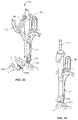
- FIG. 1is a side view of components of one embodiment of a surgical system in accordance with the principles of the present disclosure
- FIG. 2is a perspective view of components of one embodiment of a surgical system in accordance with the principles of the present disclosure
- FIG. 3is a side view of components of one embodiment of a surgical system in accordance with the principles of the present disclosure
- FIG. 4is a side view of components of one embodiment of a surgical system in accordance with the principles of the present disclosure
- FIG. 5is a side view of components of one embodiment of a surgical system in accordance with the principles of the present disclosure
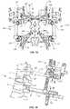
- FIG. 6is a perspective view of components of one embodiment of a surgical system in accordance with the principles of the present disclosure
- FIG. 7is a plan view of components of one embodiment of a surgical system in accordance with the principles of the present disclosure disposed with vertebrae;
- FIG. 8is a side view of components of one embodiment of a surgical system in accordance with the principles of the present disclosure disposed with vertebrae;
- FIG. 9is a side view of components of one embodiment of a surgical system in accordance with the principles of the present disclosure.
- FIG. 10is a side view of components of one embodiment of a surgical system in accordance with the principles of the present disclosure.
- FIG. 11is a plan view of components of one embodiment of a surgical system in accordance with the principles of the present disclosure disposed with vertebrae;
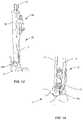
- FIG. 12is a side view of components of one embodiment of a surgical system in accordance with the principles of the present disclosure disposed with vertebrae;
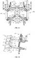
- FIG. 13is a perspective view of components of one embodiment of a surgical system in accordance with the principles of the present disclosure disposed with vertebrae;
- FIG. 14is a perspective view of components of one embodiment of a surgical system in accordance with the principles of the present disclosure disposed with vertebrae;
- FIG. 15is a plan view of components of one embodiment of a surgical system in accordance with the principles of the present disclosure disposed with vertebrae;
- FIG. 16is a side view of components of one embodiment of a surgical system in accordance with the principles of the present disclosure disposed with vertebrae;
- FIG. 17is a plan view of components of one embodiment of a surgical system in accordance with the principles of the present disclosure disposed with vertebrae;
- FIG. 18is a side view of components of one embodiment of a surgical system in accordance with the principles of the present disclosure disposed with vertebrae;
- FIG. 19is a plan view of components of one embodiment of a surgical system in accordance with the principles of the present disclosure disposed with vertebrae;
- FIG. 20is a side view of components of one embodiment of a surgical system in accordance with the principles of the present disclosure disposed with vertebrae;
- FIG. 21is a plan view of components of one embodiment of a surgical system in accordance with the principles of the present disclosure disposed with vertebrae;
- FIG. 22is a side view of components of one embodiment of a surgical system in accordance with the principles of the present disclosure disposed with vertebrae;
- FIG. 23is a perspective view of components of one embodiment of a surgical system in accordance with the principles of the present disclosure disposed with vertebrae;
- FIG. 24is a perspective view of components of one embodiment of a surgical system in accordance with the principles of the present disclosure disposed with vertebrae;
- FIG. 25is a side view of vertebrae
- FIG. 26is a side view of components of one embodiment of a surgical system in accordance with the principles of the present disclosure disposed with vertebrae;
- FIG. 27is a side view of components of one embodiment of a surgical system in accordance with the principles of the present disclosure disposed with vertebrae;
- FIG. 28is a perspective view of components of one embodiment of a surgical system in accordance with the principles of the present disclosure disposed with vertebrae;
- FIG. 29is a perspective view of components of one embodiment of a surgical system in accordance with the principles of the present disclosure disposed with vertebrae.
- the present surgical systemincludes surgical instruments that allow vertebral manipulation to treat spinal disorders, as described herein, for managing lordosis and/or kyphosis restoration.
- the surgical instrumentsallow for parallel distraction and/or compression of vertebral tissue.
- the present surgical systemincludes a trauma instrument. In some embodiments, the present surgical system is utilized with a method to correct complex spinal deformities. In some embodiments, the present surgical system is utilized with a method to treat degenerative spinal disorders and/or employed with transforaminal lumbar interbody fusion procedures. In some embodiments, the present surgical system is configured for utilization with sagittal adjusting screws (SAS), fixed axis screws (FAS) and/or multi-axial screws (MAS). In some embodiments, the present surgical system comprises a plurality of distractors, such as, for example, two distractors disposed along a side of vertebrae to perform a ligamentotaxy procedure. In some embodiments, the present surgical system comprises a single distractor to treat degenerative spinal disorders, for example, for disposal along a side of vertebrae oriented for decompression and/or interbody cage insertion.
- SASsagittal adjusting screws
- FASfixed axis screws
- MASmulti-axial screws
- the present surgical systemcomprises a plurality of distractors
- the present surgical systemis employed with a surgical technique for an open approach procedure.
- the present surgical systemincludes an implant support having a screw manipulation stick.
- the implant supportis positioned to provide access to a screw receiver to facilitate rod insertion.
- the present surgical systemincludes an adaptor connected to the implant support with a pivot hinge disposed adjacent a connection point with the screw receiver.
- an implant support connected with the screw receivercan include a point of rotation at the screw receiver level.
- the present surgical systemincludes an implant support having an offset connection to a bone screw.
- the present surgical systemincludes an implant support having a slide configured for translation to move the implant support between an open orientation and a closed orientation.
- the present surgical systemincludes an alignment guide configured to facilitate location of the bone screw.
- the surgical systemincludes an adaptor connected with a surgical instrument and an angulation module having arms for connection with an implant support.
- the angulation moduleis configured for individual angulation of implant supports in a range of +/ ⁇ 20 degrees.
- a compressor/distractoris utilized for distraction and the angulation module maintains an angle of the extender with vertebrae.
- the present surgical systemis employed with a method including the steps of inserting the adaptor with an implant support at a surgical site and the step of sliding a sleeve along the implant support.
- the methodincludes the step of securing the sleeve to the implant support.
- the methodincludes the steps of connecting the implant support to the screws using the guide to facilitate alignment.
- the present surgical systemis employed with a surgical technique including distraction of the posterior ligament. In some embodiments, the present surgical system is employed with a surgical technique for distracting vertebral tissue in a parallel configuration. In some embodiments, the present surgical system is employed with a surgical technique including correction of vertebral angle by manual manipulation of the implant support. In some embodiments, the angulation module is configured to maintain a corrected angle during manual manipulation of the implant support. In some embodiments, the present surgical system is employed with a surgical technique including contouring and insertion of a spinal rod. In some embodiments, the surgical system includes a rod reduction lever configured to reduce the spinal rod with the screws.
- the present surgical systemincludes a surgical instrument configured to compress or distract and restore curvature of a spine.
- the present surgical systemincludes instruments and tools for correcting a sagittal deformity and rebalancing a spine of a body.
- the present surgical systemis employed to treat degenerative deformities of a spine in a sagittal plane, for example, degenerative kyphosis.
- the present surgical systemis employed to treat hyper-kyphosis and flat lumbar back, including disorders that create an unbalance of a body and loss of alignment between body parts.
- the present surgical systemprovides a selected amount of correction to apply a selected balance to a spine and provides control and adjustment to the amount of correction.
- the present surgical systemincludes a series of tools and instruments that allow formulation of a type of correction applied and can control the correction stabilization using posterior instrumentation.
- one or all of the components of the surgical systemare disposable, peel-pack, pre-packed sterile devices used with a spinal construct.
- One or all of the components of the surgical systemmay be reusable.
- the surgical systemmay be configured as a kit with multiple sized and configured components.
- the present disclosuremay be employed to treat spinal disorders such as, for example, degenerative disc disease, disc herniation, osteoporosis, spondylolisthesis, stenosis, scoliosis and other curvature abnormalities, kyphosis, tumor and fractures.
- spinal disorderssuch as, for example, degenerative disc disease, disc herniation, osteoporosis, spondylolisthesis, stenosis, scoliosis and other curvature abnormalities, kyphosis, tumor and fractures.
- the present disclosuremay be employed with other osteal and bone related applications, including those associated with diagnostics and therapeutics.
- the disclosed surgical system and methodsmay be alternatively employed in a surgical treatment with a patient in a prone or supine position, and/or employ various surgical approaches to the spine, including posterior, posterior mid-line, and in other body regions.
- the present disclosuremay also be alternatively employed with procedures for treating the lumbar, cervical, thoracic, sacral and pelvic regions of a spinal column.
- the system and methods of the present disclosuremay also be used on animals, bone models and other non-living substrates, such as, for example, in training, testing and demonstration.
- Rangesmay be expressed herein as from “about” or “approximately” one particular value and/or to “about” or “approximately” another particular value. When such a range is expressed, another embodiment includes from the one particular value and/or to the other particular value. Similarly, when values are expressed as approximations, by use of the antecedent “about,” it will be understood that the particular value forms another embodiment. It is also understood that all spatial references, such as, for example, horizontal, vertical, top, upper, lower, bottom, left and right, are for illustrative purposes only and can be varied within the scope of the disclosure. For example, the references “upper” and “lower” are relative and used only in the context to the other, and are not necessarily “superior” and “inferior”.
- treating or “treatment” of a disease or conditionrefers to performing a procedure that may include administering one or more drugs to a patient (human, normal or otherwise or other mammal), employing implantable devices, and/or employing instruments that treat the disease, such as, for example, microdiscectomy instruments used to remove portions bulging or herniated discs and/or bone spurs, in an effort to alleviate signs or symptoms of the disease or condition. Alleviation can occur prior to signs or symptoms of the disease or condition appearing, as well as after their appearance.
- treating or treatmentincludes preventing or prevention of disease or undesirable condition (e.g., preventing the disease from occurring in a patient, who may be predisposed to the disease but has not yet been diagnosed as having it).
- treating or treatmentdoes not require complete alleviation of signs or symptoms, does not require a cure, and specifically includes procedures that have only a marginal effect on the patient.
- Treatmentcan include inhibiting the disease, e.g., arresting its development, or relieving the disease, e.g., causing regression of the disease.
- treatmentcan include reducing acute or chronic inflammation; alleviating pain and mitigating and inducing re-growth of new ligament, bone and other tissues; as an adjunct in surgery; and/or any repair procedure.
- tissueincludes soft tissue, ligaments, tendons, cartilage and/or bone unless specifically referred to otherwise.
- FIGS. 1-6there are illustrated components of a surgical system 10 .
- the components of surgical system 10can be fabricated from biologically acceptable materials suitable for medical applications, including metals, synthetic polymers, ceramics and bone material and/or their composites.
- the components of surgical system 10individually or collectively, can be fabricated from materials such as stainless steel alloys, commercially pure titanium, titanium alloys, Grade 5 titanium, super-elastic titanium alloys, cobalt-chrome alloys, superelastic metallic alloys (e.g., Nitinol, super elasto-plastic metals), ceramics and composites thereof such as calcium phosphate (e.g., SKELITETM), thermoplastics such as polyaryletherketone (PAEK) including polyetheretherketone (PEEK), polyetherketoneketone (PEKK) and polyetherketone (PEK), carbon-PEEK composites, PEEK-BaSO 4 polymeric rubbers, polyethylene terephthalate (PET), fabric, silicone, polyurethane, silicone-polyurethane copolymers, polymeric rubber
- Various components of surgical system 10may have material composites, including the above materials, to achieve various desired characteristics such as strength, rigidity, elasticity, compliance, biomechanical performance, durability and radiolucency or imaging preference.
- the components of surgical system 10individually or collectively, may also be fabricated from a heterogeneous material such as a combination of two or more of the above-described materials.
- the components of surgical system 10may be monolithically formed, integrally connected or include fastening elements and/or instruments, as described herein.
- Surgical system 10is employed, for example, with a minimally invasive procedure, including percutaneous techniques, mini-open and open surgical techniques to deliver and introduce instrumentation and/or components of spinal constructs at a surgical site within a body of a patient, for example, a section of a spine.
- one or more of the components of surgical system 10are configured for engagement with spinal constructs attached with vertebrae to manipulate tissue and/or correct a spinal disorder, such as, for example, a sagittal deformity, as described herein.
- surgical system 10may be employed with surgical procedures, such as, for example, corpectomy, discectomy and/or fracture/trauma treatment and may include fusion and/or fixation that employ implants to restore the mechanical support function of vertebrae.
- Surgical system 10includes implant supports, such as, for example, sticks 12 .
- Sticks 12are engageable with bone fasteners, such as, for example, FAS 200 and/or SAS 600 , and a surgical instrument, such as, for example, a compressor/distractor 250 via adaptors 50 to manipulate tissue, as shown in FIG. 6 and described herein.
- bone fastenerssuch as, for example, FAS 200 and/or SAS 600
- a surgical instrumentsuch as, for example, a compressor/distractor 250 via adaptors 50 to manipulate tissue, as shown in FIG. 6 and described herein.
- Stick 12includes a body, such as, for example, a sleeve 52 .
- Sleeve 52extends along an axis X 1 , as shown in FIG. 1 .
- Sleeve 52includes an extension 72 and extension 74 .
- Extensions 72 , 74are relatively moveable via relative translation of a translation element, such as, for example, a slide 76 .
- Slide 76is manipulated for translation within channel 62 to move extensions 72 , 74 between an open orientation, as shown in FIG. 4 , and a closed, capture orientation, as shown in FIG. 3 .
- Slide 76is translated, in a direction shown by arrow M in FIG. 4 , to cause extensions 72 , 74 to rotate and expand, in a direction shown by arrows N, to the open orientation.
- pins 73are seated in a bottom of slots 75 of slide 76 .
- Slide 76is translated, in a direction shown by arrow O in FIG. 3 , to cause extensions 72 , 74 to rotate and contract, in a direction shown by arrows P, to the closed orientation to capture FAS 200 and/or SAS 600 , which can include a locked configuration of sleeve 52 with a bone screw.
- pins 73are seated in at the top of slots 75 .
- extensions 72 , 74are flexible to facilitate contraction.
- Sleeve 52includes a surface 60 that defines a channel 62 .
- Channel 62is configured for disposal of slide 76 , as described herein.
- Sleeve 52is engageable with an adaptor 50 , as described herein, such that adaptor 50 is pivotable and/or rotatable relative to sleeve 52 , FAS 200 and/or SAS 600 . Rotation of adaptor 50 facilitates engagement of adaptor 50 with compressor/distractor 250 , as described herein.
- Sleeve 52includes a capture portion 64 configured to connect stick 12 with a receiver of FAS screw 200 ( FIG. 9 ) and/or SAS 600 ( FIG. 10 ). Positioning of stick 12 with an arm of receiver 202 or receiver 602 provides for direct access to receiver 202 or receiver 602 to facilitate insertion of rod 210 .
- stick 12is connected with a receiver at a point of rotation at the receiver level.
- one or more sticks 12are manipulable, as described herein, to provide a counter-torque for small deformity maneuvers and manipulation of vertebrae during a surgical treatment, for example, to displace, pull, twist or align vertebrae.
- Adaptor 50extends from and is pivotable relative to sleeve 52 , as shown in FIGS. 1 and 2 .
- Adaptor 50extends between an end 54 and an end 56 .
- End 54is connected to sleeve 52 by a pin hinge 58 .
- Pin 58facilitates rotation of adaptor 50 relative to sleeve 52 , FAS 200 and/or SAS 600 .
- adaptor 50may be variously oriented relative to sleeve 52 , such as, for example, transverse, perpendicular, angular and/or offset.
- Rotation of arm 80facilitates connection of adaptor 50 and sticks 12 with compressor/distractor 250 , as described herein.
- End 56includes an arm 80 extending therefrom.
- arm 80is may be variously oriented relative to axis X 1 , such as, for example, parallel, perpendicular, angular and/or offset.
- Arm 80includes a surface 82 that defines a threaded lock surface 84 .
- Surface 84is engageable with a lock nut 274 to fix compressor/distractor 250 and an angulation module 266 with sticks 12 and adaptors 50 , as described herein.
- surface 84may have alternative locking and/or tool engaging surfaces, such as, for example, rectangular, polygonal, hexalobe, oval, irregular, cruciform, phillips, square, polygonal or star cross sectional configuration.
- Compressor/distractor 250includes a longitudinal element, such as, for example, a rack 252 , as shown in FIG. 6 .
- Rack 252extends between an end 254 and an end 256 defining a longitudinal axis A 1 .
- Rack 252is configured to connect adjacent sticks 12 .
- Rack 252includes an outer surface 258 having a plurality of teeth, such as, for example, splines 260 engageable with an arm 282 , as described herein.
- Rack 252includes an arm 262 extending from end 254 .
- Arm 262includes a surface that defines an opening (not shown) configured for disposal of surface 84 for mounting compressor/distractor 250 with stick 12 , angulation module 266 and adaptor 50 .
- Rack 252includes arm 282 that is axially translatable along axis A 1 relative to arm 262 .
- Arm 282includes a surface that defines an opening (not shown) configured for disposal of surface 84 for mounting compressor/distractor 250 with stick 12 , angulation module 266 and adaptor 50 .
- Compressor/distractor 250includes a ratchet, which includes splines 260 and arm 282 engageable in a bi-directional and/or two-way ratchet configuration.
- Arm 282includes a latch 300 that includes a pinion or pawl (not shown) engageable with splines 260 .
- Latch 300is pivotable relative to arm 282 for disposal in a distraction position, as shown in FIG. 6 . In the distraction position, latch 300 engages rack 252 to allow axial and/or incremental translation of arm 282 relative to arm 262 /rack 252 , in the direction shown by arrow A, and prevents axial translation of arm 282 relative to arm 262 /rack 252 , in an opposing direction shown by arrow B. As such, distraction of vertebral tissue connected with sticks 12 can be performed.
- Latch 300is pivotable relative to arm 282 for disposal in a neutral position (not shown). In the neutral position, latch 300 disengages from rack 252 to allow free axial translation of arm 262 /rack 252 relative to arm 282 . Latch 300 is pivotable relative to arm 282 for disposal in a compression position (not shown). In the compression position, latch 300 engages rack 252 to allow axial and/or incremental translation of arm 282 relative to arm 262 /rack 252 , in the direction shown by arrow B, and prevents axial translation of arm 282 relative to arm 262 /rack 252 , in an opposing direction shown by arrow A. As such, compression of vertebral tissue connected with sticks 12 can be performed.
- a rotatable key 302includes a gear surface engageable with splines 260 to axially and/or incrementally translate rack 252 to facilitate distraction and/or compression, as described herein.
- Angulation modules 266are connectable with compressor/distractor 250 , sticks 12 and adaptor 50 , as shown in FIG. 6 .
- Module 266includes a surface that defines an opening (not shown) configured for disposal of surface 84 for mounting module 266 with compressor/distractor 250 , sticks 12 and adaptor 50 .
- Module 266includes a body 267 that extends between an end 268 and an end 270 .
- Module 266includes a longitudinal element, such as, for example, a rack 280 , as shown in FIG. 6 .
- Rack 280includes an outer surface having a plurality of teeth, such as, for example, splines 284 .
- Rack 280includes spaced apart arms 290 that define a cavity 292 . Arms 290 are configured for capture of sticks 12 . Modules 266 are fixed with sticks 12 to allow for angulation and/or correction of vertebral tissue connected with sticks 12 , individually, in combination or simultaneously. In some embodiments, engagement of sticks 12 with module 266 facilitates manipulation of vertebrae attached with sticks 12 through an angular range of 0 through 20 degrees of correction and/or relative to an initial orientation of vertebrae.
- Body 267includes a ratchet, which includes splines 284 and a latch 286 engageable in a bi-directional and/or two-way ratchet configuration.
- Latch 286includes a slider 288 and a lever 294 having a pinion or pawl (not shown) engageable with splines 284 .
- Slider 288engages lever 294 , which is pivotable relative to body 267 for disposal in a lordosis position, as shown in FIG. 6 .
- the pawl of lever 294engages rack 280 in an orientation to allow axial and/or incremental translation of rack 280 relative to body 267 , in the directions shown by arrows C, and prevents axial translation of rack 280 relative to body 267 , in opposing directions shown by arrows D.
- angulation of vertebral tissue connected with sticks 12 to achieve lordosiscan be performed.
- Slider 288is engageable with lever 294 , which is pivotable relative to body 267 in an opposing orientation for disposal in a kyphosis position.
- the pawl of lever 294engages rack 280 in an orientation to allow axial and/or incremental translation of rack 280 relative to body 267 , in the directions shown by arrows D, and prevents axial translation of rack 280 relative to body 267 , in opposing directions shown by arrows C.
- angulation of vertebral tissue connected with sticks 12 to achieve kyphosiscan be performed.
- connection of module 266 with adaptor 50 and sticks 12facilitates correction of a vertebral angle of vertebrae, for example, to achieve a selected lordosis and/or kyphosis, via manipulation of modules 266 , as described herein.
- modules 266are manipulated to manually correct a vertebral angle of vertebrae by pivoting sticks 12 .
- modules 266are connected with adaptor 50 , compressor/distractor 250 and/or sticks 12 to maintain a corrected vertebral angle of vertebrae during distraction and/or compression, as described herein.
- Surgical system 10includes an alignment guide 90 , as shown in FIG. 5 .
- Guide 90is configured for disposal with a receiver of FAS 200 and/or SAS 600 to orient stick 12 and facilitate identifying, locating and/or engaging stick 12 with the receiver of FAS 200 and/or SAS 600 .
- FAS 200includes a receiver 202 having a pair of spaced apart arms 204 , 204 a , as shown in FIG. 9 .
- Receiver 202is configured for engagement with sticks 12 , as described herein.
- Arms 204 , 204 ainclude an inner surface that defines a U-shaped passageway 206 for disposal of a spinal rod 210 , as described herein.
- the inner surface of receiver 202includes a thread form configured for engagement with a set screw 212 ( FIG.
- SAS 600has a receiver 602 , as shown in FIG. 10 .
- Receiver 602is configured for engagement with sticks 12 , as described herein and includes a shaft 608 configured for penetrating tissue.
- Receiver 602includes a saddle 603 that is selectively translatable within receiver 602 in a sagittal plane to accommodate sagittal anatomical differences. The saddle receives and movably supports rod 210 such that rod 210 is movable within receiver 602 through an angular range.
- surgical system 10In assembly, operation and use, surgical system 10 , similar to the systems and methods described herein, is employed with a surgical procedure for treatment of a spine of a patient including vertebrae V, as shown in FIGS. 7-29 .
- Surgical system 10is employed with a procedure for treatment of an applicable condition or injury of an affected section of a spinal column and adjacent areas within a body.
- vertebrae Vincludes a vertebral level V 1 , a vertebral level V 2 and a vertebral level V 3 , as shown in FIGS. 7 and 8 .
- Diseased and/or damaged vertebrae and intervertebral discsare disposed at vertebra V 2 between vertebrae V 1 and V 3 .
- components of surgical system 10are configured for insertion with a vertebral space to space apart articular joint surfaces, provide support and maximize stabilization of vertebrae V.
- surgical system 10may be used in any existing surgical method or technique including open surgery, mini-open surgery, minimally invasive surgery and percutaneous surgical implantation, whereby vertebrae V is accessed through a mini-incision, or sleeve that provides a protected passageway to the area.
- a cutting instrument(not shown) creates a surgical pathway for implantation of components of surgical system 10 .
- a preparation instrument(not shown) can be employed to prepare tissue surfaces of vertebrae V, as well as for aspiration and irrigation of a surgical region.
- Pilot holes or the likeare made in selected vertebrae V 1 and V 3 for receiving bone screws, such as, for example, FAS 200 , 200 a .
- a driver(not shown) is disposed adjacent vertebrae V at a surgical site and is manipulated to drive, torque, insert or otherwise connect FAS 200 , 200 a with vertebrae V 1 and V 3 .
- FAS 200 , 200 aare engaged with vertebrae V along a lateral side L and a contra-lateral side CL of vertebrae V.
- Sticks 12are disposed in an open orientation, as described herein, and guide 90 , as shown in FIG.
- Sticks 12 /adaptors 50are engaged with FAS 200 and sticks 12 a /adaptors 50 are engaged with FAS 200 a .
- Sticks 12 , 12 aare disposed in a closed orientation, as described herein and shown in FIGS. 11, 12 and 14 , to capture FAS 200 , 200 a.
- Compressor/distractor 250 and modules 266are mounted with sticks 12 , 12 a /adaptors 50 via surface 84 and lock nut 274 for fixation therewith, as described herein and shown in FIGS. 15 and 16 .
- Arms 290 of modules 266capture sticks 12 , 12 a /adaptors 50 , as described herein.
- Modules 266are fixed with sticks 12 , 12 a /adaptors 50 , to allow for angulation and/or correction of vertebrae V connected with sticks 12 , 12 a /adaptors 50 .
- latch 286 of module 266is disposable in a lordosis position, as described herein, to allow translation of rack 280 , in the directions shown by arrows C, and prevent translation of rack 280 , in the directions shown by arrows D, relative to body 267 .
- angulation of vertebrae V 1 , V 3 connected with sticks 12 , 12 a /adaptors 50 to achieve a selected lordosiscan be performed.
- Module 266prevents translation of rack 280 , in the directions shown by arrows D, relative to body 267 to maintain the selected lordosis during distraction and/or compression, as described herein.
- correction and/or angulation of vertebrae V 1 , V 3can be performed directly with sticks 12 , 12 a /adaptors 50 and modules 266 maintain the selected correction and/or angulation of vertebrae V 1 , V 3 .
- Compressor/distractor 250is connected with sticks 12 , 12 a /adaptors 50 , to allow for distraction and/or compression of vertebrae V connected with sticks 12 , 12 a /adaptors 50 , as described herein and shown in FIGS. 17 and 18 .
- latch 300is pivotable to the distraction position, as described herein, to allow translation of arm 282 , in the direction shown by arrow A, and prevent translation of arm 282 , in the direction shown by arrow B, relative to arm 262 /rack 252 .
- distraction of vertebrae V 1 , V 3 connected with sticks 12 , 12 a /adaptors 50can be performed.
- a key 302is engageable with splines 260 to translate rack 252 for distraction.
- keys 302can simultaneously engage compressor/distractors 250 connected with vertebrae V on sides L, CL to perform parallel distraction of vertebrae V 1 , V 3 .
- Rod 210is contoured and disposed within receivers 202 , 202 a , as shown in FIGS. 21 and 22 .
- a surgical instrumentsuch as, for example, a rod reducer 300 is translated into engagement with rods 210 , 210 a to reduce rods 210 , 210 a with receivers 202 , 202 a .
- rod reducer 300is attachable with compressor/distractor 250 and includes a lever 302 having a linkage 304 that is manipulable for rotation to seat and/or reduce rods 210 , 210 a with receivers 202 , 202 a .
- FIG. 23rod reducer 300 is attachable with compressor/distractor 250 and includes a lever 302 having a linkage 304 that is manipulable for rotation to seat and/or reduce rods 210 , 210 a with receivers 202 , 202 a .
- rod reducer 300is attachable with compressor/distractor 250 and includes a screw/threaded longitudinal driver 410 that is rotatable to incrementally translate and seat and/or reduce rods 210 , 210 a with receivers 202 , 202 a .
- Driver 410is inserted with set screws 212 to fix rod 210 with FAS 200 .
- Vertebrae Vis aligned to a selected orientation for correction, as shown in FIGS. 25-27 .
- surgical system 10can be employed with a degenerative fusion to facilitate decompression, interbody access and interbody implant.
- modules 266are disposed outside of sticks 12 and compressor/distractor 250 is disposed in a distraction position to distract vertebrae V.
- compressor/distractor 250is disposed in a neutral position, as described herein, and sticks 12 are crossed.
- a crossing block 502captures the crossed sticks 12 .
- Compressor/distractor 250is disposed in a compression position, as described herein, and key 302 is rotated to selectively compress vertebrae V.
- surgical system 10Upon completion of a procedure, as described herein, the surgical instruments, assemblies and non-implanted components of surgical system 10 are removed and the incision(s) are closed.
- One or more of the components of surgical system 10can be made of radiolucent materials such as polymers. Radiomarkers may be included for identification under x-ray, fluoroscopy, CT or other imaging techniques.
- the use of surgical navigation, microsurgical and image guided technologiesmay be employed to access, view and repair spinal deterioration or damage, with the aid of surgical system 10 .
- surgical system 10may include one or a plurality of plates, connectors and/or bone fasteners for use with a single vertebral level or a plurality of vertebral levels.
- surgical system 10includes one or a plurality of alternate surgical instruments, each configured for mating engagement in a quick release configuration with spinal constructs, as described herein. This configuration facilitates the interchangeability of the spinal constructs with the alternate surgical instruments.
- surgical system 10includes one or a plurality of alternate surgical instruments, such as, for example, inserters, extenders, reducers, spreaders, distractors, blades, retractors, clamps, forceps, elevators and drills, which may be alternately sized and dimensioned, and arranged as a kit.
- surgical system 10includes an agent, which may be disposed, packed, coated or layered within, on or about the components and/or surfaces of surgical system 10 .
- the agentmay include bone growth promoting material, such as, for example, bone graft to enhance fixation of the components and/or surfaces of surgical system 10 with vertebrae.
- the agentmay include one or a plurality of therapeutic agents and/or pharmacological agents for release, including sustained release, to treat, for example, pain, inflammation and degeneration.
Landscapes
- Health & Medical Sciences (AREA)
- Orthopedic Medicine & Surgery (AREA)
- Neurology (AREA)
- Life Sciences & Earth Sciences (AREA)
- Surgery (AREA)
- Heart & Thoracic Surgery (AREA)
- Engineering & Computer Science (AREA)
- Biomedical Technology (AREA)
- Nuclear Medicine, Radiotherapy & Molecular Imaging (AREA)
- Medical Informatics (AREA)
- Molecular Biology (AREA)
- Animal Behavior & Ethology (AREA)
- General Health & Medical Sciences (AREA)
- Public Health (AREA)
- Veterinary Medicine (AREA)
- Surgical Instruments (AREA)
- Prostheses (AREA)
Abstract
Description
Claims (20)
Applications Claiming Priority (1)
| Application Number | Priority Date | Filing Date | Title |
|---|---|---|---|
| PCT/IB2017/000290WO2018150215A1 (en) | 2017-02-17 | 2017-02-17 | Surgical system and method |
Publications (2)
| Publication Number | Publication Date |
|---|---|
| US20200054362A1 US20200054362A1 (en) | 2020-02-20 |
| US11484349B2true US11484349B2 (en) | 2022-11-01 |
Family
ID=58537041
Family Applications (1)
| Application Number | Title | Priority Date | Filing Date |
|---|---|---|---|
| US16/487,064Active2037-04-25US11484349B2 (en) | 2017-02-17 | 2017-02-17 | Surgical system and method |
Country Status (4)
| Country | Link |
|---|---|
| US (1) | US11484349B2 (en) |
| EP (1) | EP3582703B1 (en) |
| CN (1) | CN110267610B (en) |
| WO (1) | WO2018150215A1 (en) |
Cited By (6)
| Publication number | Priority date | Publication date | Assignee | Title |
|---|---|---|---|---|
| US20210212723A1 (en)* | 2009-05-20 | 2021-07-15 | DePuy Synthes Products, Inc. | Patient-Mounted Retraction |
| US20210282820A1 (en)* | 2018-06-13 | 2021-09-16 | Nuvasive, Inc. | Rod Reduction Assemblies and Related Methods |
| US12096923B2 (en) | 2020-07-10 | 2024-09-24 | Warsaw Orthopedic, Inc. | Tissue retractor, retraction modules, and associated methods |
| US12349889B2 (en) | 2020-07-10 | 2025-07-08 | Warsaw Orthopedic, Inc. | Tissue retractor, retraction modules, and associated methods |
| US12383249B2 (en) | 2020-07-10 | 2025-08-12 | Warsaw Orthopedic, Inc. | Tissue retractor, retraction modules, and associated methods |
| US12440248B2 (en) | 2022-06-28 | 2025-10-14 | DePuy Synthes Products, Inc. | Minimally invasive instrument set, devices, and related methods |
Families Citing this family (8)
| Publication number | Priority date | Publication date | Assignee | Title |
|---|---|---|---|---|
| US11484349B2 (en)* | 2017-02-17 | 2022-11-01 | Warsaw Orthopedic, Inc. | Surgical system and method |
| WO2018150214A1 (en)* | 2017-02-17 | 2018-08-23 | Warsaw Orthopedic, Inc. | Surgical system |
| EP3958757B1 (en) | 2019-04-23 | 2024-11-27 | Warsaw Orthopedic, Inc. | Surgical system |
| EP3958762B1 (en)* | 2019-04-23 | 2024-11-20 | Warsaw Orthopedic, Inc. | Surgical system |
| EP3958758A4 (en)* | 2019-04-23 | 2022-12-07 | Warsaw Orthopedic, Inc. | Surgical system and method |
| EP3958761B1 (en) | 2019-04-23 | 2023-11-15 | Warsaw Orthopedic, Inc. | Surgical system |
| WO2020219019A1 (en) | 2019-04-23 | 2020-10-29 | Warsaw Orthopedic, Inc. | Surgical system and method |
| WO2021206723A1 (en) | 2020-04-09 | 2021-10-14 | Warsaw Orthopedic, Inc. | Surgical system and method |
Citations (73)
| Publication number | Priority date | Publication date | Assignee | Title |
|---|---|---|---|---|
| US20050245928A1 (en)* | 2004-05-03 | 2005-11-03 | Innovative Spinal Technologies | System and method for displacement of bony structures |
| US20080077155A1 (en)* | 2006-09-25 | 2008-03-27 | Jennifer Diederich | System and method for displacement of bony structures |
| US20080119852A1 (en)* | 2006-11-20 | 2008-05-22 | Dalton Brian E | Bone repair device and method |
| US20080125788A1 (en)* | 2006-09-26 | 2008-05-29 | Cohen Dan S | Percutaneous instrument assembly |
| US20080154280A1 (en) | 2006-12-22 | 2008-06-26 | Joerg Schumacher | Surgical instrument and osteosynthesis device |
| US20090204159A1 (en)* | 2008-02-12 | 2009-08-13 | Warsaw Orthopedic, Inc. | Methods and devices for deformity correction |
| US7666189B2 (en)* | 2004-09-29 | 2010-02-23 | Synthes Usa, Llc | Less invasive surgical system and methods |
| US8100828B2 (en)* | 2002-11-23 | 2012-01-24 | George Frey | Distraction and retraction system for spinal surgery |
| US20120035611A1 (en)* | 2010-08-06 | 2012-02-09 | Warsaw Orthopedic, Inc. | Measuring instrument for sizing an elongate stabilization element |
| US8137356B2 (en)* | 2008-12-29 | 2012-03-20 | Zimmer Spine, Inc. | Flexible guide for insertion of a vertebral stabilization system |
| US20120116467A1 (en)* | 2008-07-31 | 2012-05-10 | Zimmer Spine, Inc. | Surgical instrument with integrated compression and distraction mechanisms |
| US20120197309A1 (en)* | 2011-01-28 | 2012-08-02 | Warsaw Orthopedic, Inc. | Bone Anchor Including an Elongate Post With Break-Off Features |
| US8357184B2 (en)* | 2009-11-10 | 2013-01-22 | Nuvasive, Inc. | Method and apparatus for performing spinal surgery |
| US8460308B2 (en)* | 2008-10-14 | 2013-06-11 | Trinity Orthopedics, Llc. | Insertion and reduction tool for pedicle screw assembly |
| US8475467B2 (en)* | 2009-12-07 | 2013-07-02 | Globus Medical, Inc. | Derotation apparatus for treating spinal irregularities |
| US20130211453A1 (en)* | 2012-02-15 | 2013-08-15 | Warsaw Orthopedic, Inc. | Spinal correction system and method |
| US20130245692A1 (en) | 2012-03-19 | 2013-09-19 | Kyle Hayes | Spondylolisthesis reduction system |
| US20130304130A1 (en)* | 2004-02-27 | 2013-11-14 | Roger P. Jackson | Tool system for dynamic spinal implants |
| US8617218B2 (en)* | 2011-05-13 | 2013-12-31 | Warsaw Orthoepdic, Inc. | Bone anchor extenders |
| US20140039567A1 (en)* | 2012-08-01 | 2014-02-06 | Aesculap Ag | Surgical apparatus |
| US20140039557A1 (en)* | 2007-12-05 | 2014-02-06 | DePuy Synthes Products, LLC | System and method of manipulating spinal constructs |
| US20140052197A1 (en)* | 2012-08-17 | 2014-02-20 | Warsaw Orthopedic, Inc. | Spinal implant system and method |
| US20140058464A1 (en)* | 2012-08-23 | 2014-02-27 | Synthes Usa, Llc | Bi-planar persuader |
| US8672944B2 (en)* | 2008-06-27 | 2014-03-18 | K2M, Inc. | System and method for performing spinal surgery |
| US20140107707A1 (en)* | 2011-02-10 | 2014-04-17 | Robert A. Rovner | Table anchored scoliosis de-rotation system and method |
| US8702713B2 (en)* | 2011-01-26 | 2014-04-22 | Warsaw Orthopedic, Inc. | Instruments and techniques for adjusting relative positioning of bones or bony tissues |
| US8747409B2 (en)* | 2010-12-03 | 2014-06-10 | Zimmer Spine | Surgical instrument for positioning a spinal rod |
| US20140228899A1 (en)* | 2012-12-12 | 2014-08-14 | Wright Medical Technology, Inc. | Orthopedic compression/distraction device |
| US20140275793A1 (en)* | 2013-03-15 | 2014-09-18 | John Song | Minimally Invasive Retractor |
| US20140277168A1 (en)* | 2007-10-23 | 2014-09-18 | Clark Hutton | Rod inserter and methods of use |
| US20140311264A1 (en)* | 2013-04-20 | 2014-10-23 | Degen Medical, Inc. | Anchor Tower |
| US8900237B2 (en)* | 2007-08-31 | 2014-12-02 | DePuy Synthes Products, LLC | Minimally invasive guide system |
| US8906034B2 (en)* | 2012-04-17 | 2014-12-09 | Alphatec Spine, Inc. | Instrument and method for spinal compression and distraction |
| US20150045834A1 (en)* | 2013-08-06 | 2015-02-12 | Warsaw Orthopedic, Inc. | Spinal implant system |
| US20150066088A1 (en)* | 2013-09-05 | 2015-03-05 | Warsaw Orthopedic, Inc. | Surgical instrument and method |
| US8992536B2 (en)* | 2010-06-24 | 2015-03-31 | Warsaw Orthopedic, Inc. | Coplanar deformity correction system |
| US20150164569A1 (en) | 2013-12-13 | 2015-06-18 | Stryker European Holdings I, Llc | Tissue retraction and vertebral displacement devices, systems, and methods for posterior spinal fusion |
| US9066761B2 (en)* | 2012-08-17 | 2015-06-30 | Warsaw Orthopedic, Inc. | Spinal implant system and method |
| US9101412B2 (en)* | 2010-09-09 | 2015-08-11 | DePuy Synthes Products, Inc. | Vertebral adjustment systems for spine alignment |
| US9179957B2 (en)* | 2012-08-09 | 2015-11-10 | Spinecraft, LLC | Systems, assemblies and methods for spinal derotation |
| US9204909B2 (en)* | 2011-07-13 | 2015-12-08 | Warsaw Orthopedic, Inc. | Spinal rod system and method |
| US9241742B2 (en)* | 2013-03-14 | 2016-01-26 | DePuy Synthes Products, Inc. | Methods and devices for polyaxial screw alignment |
| US20160089188A1 (en)* | 2014-09-25 | 2016-03-31 | Warsaw Orthopedic, Inc. | Spinal implant system and method |
| US9314273B2 (en)* | 2005-04-27 | 2016-04-19 | Globus Medical, Inc. | Percutaneous vertebral stabilization system |
| US9314281B2 (en)* | 2010-04-14 | 2016-04-19 | Aesculap Ag | Orthopaedic fixation system, targeting device for such a fixation system and orthopaedic fixation method |
| US20160262807A1 (en) | 2015-03-11 | 2016-09-15 | Warsaw Orthopedic, Inc. | Surgical instrument and method |
| US9468474B2 (en)* | 2013-02-28 | 2016-10-18 | Alphatec Spine, Inc. | Spinal deformity correction instruments and methods |
| US9480504B1 (en)* | 2013-03-15 | 2016-11-01 | Nuvasive, Inc. | Spinal alignment frame |
| US9510875B2 (en)* | 2013-03-14 | 2016-12-06 | Stryker European Holdings I, Llc | Systems and methods for percutaneous spinal fusion |
| US9795417B2 (en)* | 2014-11-24 | 2017-10-24 | Aesculap Ag | Pedicle screw system and spinal stabilization system |
| US9907582B1 (en)* | 2011-04-25 | 2018-03-06 | Nuvasive, Inc. | Minimally invasive spinal fixation system and related methods |
| US20180153585A1 (en)* | 2016-12-06 | 2018-06-07 | Marc J. LEVINE | Retractor/compression/distraction system |
| US10111650B2 (en)* | 2015-06-04 | 2018-10-30 | Minimal Invasive Technologies (Pty) Ltd. | Pedicle mountable retractor system |
| US10159579B1 (en)* | 2013-12-06 | 2018-12-25 | Stryker European Holdings I, Llc | Tubular instruments for percutaneous posterior spinal fusion systems and methods |
| US20190090864A1 (en)* | 2017-09-22 | 2019-03-28 | Medos International Sarl | Patient-mounted surgical retractor |
| US10278687B2 (en)* | 2015-08-18 | 2019-05-07 | Globus Medical, Inc. | Devices and systems for surgical retraction |
| US20190142470A1 (en)* | 2017-11-14 | 2019-05-16 | Mantiz Logitech Co., Ltd. | Spinal screw holder for minimal invasive surgery |
| US10299838B2 (en)* | 2016-02-05 | 2019-05-28 | Medos International Sarl | Method and instruments for interbody fusion and posterior fixation through a single incision |
| US20190183541A1 (en)* | 2017-12-15 | 2019-06-20 | Medos International Sarl | Unilateral implant holders and related methods |
| US20190216453A1 (en)* | 2011-12-20 | 2019-07-18 | Life Spine, Inc. | Retractor with modular tap assemblies |
| US20190231394A1 (en)* | 2018-01-29 | 2019-08-01 | Globus Medical, Inc. | Compressor/distractor |
| US10390862B2 (en)* | 2016-04-27 | 2019-08-27 | Warsaw Orthopedic, Inc. | Spinal correction system and method |
| US10398454B2 (en)* | 2015-11-09 | 2019-09-03 | Globus Medical, Inc. | MIS cross-connector |
| US20190290330A1 (en)* | 2016-10-04 | 2019-09-26 | Zbigniew Combrowski | Surgical repositioning instrument |
| US10492837B2 (en)* | 2016-08-22 | 2019-12-03 | Zimmer Biomet Spine, Inc. | Articulating derotators for deformity spinal systems and methods for use thereof |
| US20200054362A1 (en)* | 2017-02-17 | 2020-02-20 | Warsaw Orthopedic, Inc. | Surgical System and Method |
| US20200054361A1 (en)* | 2017-02-17 | 2020-02-20 | Warsaw Orthopedic, Inc. | Surgical System |
| US10588673B2 (en)* | 2015-12-02 | 2020-03-17 | Aesculap Ag | Medical instrument and medical instrumentarium |
| US20200107862A1 (en)* | 2018-10-09 | 2020-04-09 | Biedermann Technologies Gmbh & Co. Kg | System and instrument for correcting a position of bones, bone parts, or vertebrae |
| US10617449B2 (en)* | 2016-01-08 | 2020-04-14 | Stryker European Holdings I, Llc | Tap marker |
| US10772662B2 (en)* | 2014-10-23 | 2020-09-15 | Warsaw Orthopedic, Inc. | Surgical instrument and method |
| US10898239B2 (en)* | 2016-07-01 | 2021-01-26 | Nuvasive, Inc. | Spinal trauma correction and fixation |
| US10945773B2 (en)* | 2017-09-22 | 2021-03-16 | Medos International Sarl | Patient-mounted surgical support |
Family Cites Families (1)
| Publication number | Priority date | Publication date | Assignee | Title |
|---|---|---|---|---|
| US8246624B2 (en)* | 2009-07-23 | 2012-08-21 | Zimmer Spine, Inc. | Spinal rod insertion tool and method |
- 2017
- 2017-02-17USUS16/487,064patent/US11484349B2/enactiveActive
- 2017-02-17EPEP17716984.4Apatent/EP3582703B1/enactiveActive
- 2017-02-17CNCN201780086033.4Apatent/CN110267610B/enactiveActive
- 2017-02-17WOPCT/IB2017/000290patent/WO2018150215A1/ennot_activeCeased
Patent Citations (88)
| Publication number | Priority date | Publication date | Assignee | Title |
|---|---|---|---|---|
| US8100828B2 (en)* | 2002-11-23 | 2012-01-24 | George Frey | Distraction and retraction system for spinal surgery |
| US20130304130A1 (en)* | 2004-02-27 | 2013-11-14 | Roger P. Jackson | Tool system for dynamic spinal implants |
| US20050245928A1 (en)* | 2004-05-03 | 2005-11-03 | Innovative Spinal Technologies | System and method for displacement of bony structures |
| US7666189B2 (en)* | 2004-09-29 | 2010-02-23 | Synthes Usa, Llc | Less invasive surgical system and methods |
| US9314273B2 (en)* | 2005-04-27 | 2016-04-19 | Globus Medical, Inc. | Percutaneous vertebral stabilization system |
| US20080077155A1 (en)* | 2006-09-25 | 2008-03-27 | Jennifer Diederich | System and method for displacement of bony structures |
| US20080125788A1 (en)* | 2006-09-26 | 2008-05-29 | Cohen Dan S | Percutaneous instrument assembly |
| US8038699B2 (en)* | 2006-09-26 | 2011-10-18 | Ebi, Llc | Percutaneous instrument assembly |
| US9101401B2 (en)* | 2006-11-20 | 2015-08-11 | Aesculap Implant Systems, Llc | Bone repair device and method |
| US20080119852A1 (en)* | 2006-11-20 | 2008-05-22 | Dalton Brian E | Bone repair device and method |
| US20080154280A1 (en) | 2006-12-22 | 2008-06-26 | Joerg Schumacher | Surgical instrument and osteosynthesis device |
| US8900237B2 (en)* | 2007-08-31 | 2014-12-02 | DePuy Synthes Products, LLC | Minimally invasive guide system |
| US20140277168A1 (en)* | 2007-10-23 | 2014-09-18 | Clark Hutton | Rod inserter and methods of use |
| US20140039557A1 (en)* | 2007-12-05 | 2014-02-06 | DePuy Synthes Products, LLC | System and method of manipulating spinal constructs |
| US8221426B2 (en)* | 2008-02-12 | 2012-07-17 | Warsaw Orthopedic, Inc. | Methods and devices for deformity correction |
| US20090204159A1 (en)* | 2008-02-12 | 2009-08-13 | Warsaw Orthopedic, Inc. | Methods and devices for deformity correction |
| US8672944B2 (en)* | 2008-06-27 | 2014-03-18 | K2M, Inc. | System and method for performing spinal surgery |
| US20120116467A1 (en)* | 2008-07-31 | 2012-05-10 | Zimmer Spine, Inc. | Surgical instrument with integrated compression and distraction mechanisms |
| US8460308B2 (en)* | 2008-10-14 | 2013-06-11 | Trinity Orthopedics, Llc. | Insertion and reduction tool for pedicle screw assembly |
| US8137356B2 (en)* | 2008-12-29 | 2012-03-20 | Zimmer Spine, Inc. | Flexible guide for insertion of a vertebral stabilization system |
| US8357184B2 (en)* | 2009-11-10 | 2013-01-22 | Nuvasive, Inc. | Method and apparatus for performing spinal surgery |
| US8475467B2 (en)* | 2009-12-07 | 2013-07-02 | Globus Medical, Inc. | Derotation apparatus for treating spinal irregularities |
| US9005204B2 (en)* | 2009-12-07 | 2015-04-14 | Globus Medical, Inc. | Derotation apparatus for treating spinal irregularities |
| US20200315663A1 (en)* | 2009-12-07 | 2020-10-08 | Globus Medical, Inc. | Derotation apparatus for treating spinal irregularities |
| US9314281B2 (en)* | 2010-04-14 | 2016-04-19 | Aesculap Ag | Orthopaedic fixation system, targeting device for such a fixation system and orthopaedic fixation method |
| US8992536B2 (en)* | 2010-06-24 | 2015-03-31 | Warsaw Orthopedic, Inc. | Coplanar deformity correction system |
| US8834485B2 (en)* | 2010-08-06 | 2014-09-16 | Warsaw Orthopedic, Inc. | Measuring instrument for sizing an elongate stabilization element |
| US20120035611A1 (en)* | 2010-08-06 | 2012-02-09 | Warsaw Orthopedic, Inc. | Measuring instrument for sizing an elongate stabilization element |
| US9101412B2 (en)* | 2010-09-09 | 2015-08-11 | DePuy Synthes Products, Inc. | Vertebral adjustment systems for spine alignment |
| US8747409B2 (en)* | 2010-12-03 | 2014-06-10 | Zimmer Spine | Surgical instrument for positioning a spinal rod |
| US8702713B2 (en)* | 2011-01-26 | 2014-04-22 | Warsaw Orthopedic, Inc. | Instruments and techniques for adjusting relative positioning of bones or bony tissues |
| US20120197309A1 (en)* | 2011-01-28 | 2012-08-02 | Warsaw Orthopedic, Inc. | Bone Anchor Including an Elongate Post With Break-Off Features |
| US20140107707A1 (en)* | 2011-02-10 | 2014-04-17 | Robert A. Rovner | Table anchored scoliosis de-rotation system and method |
| US9907582B1 (en)* | 2011-04-25 | 2018-03-06 | Nuvasive, Inc. | Minimally invasive spinal fixation system and related methods |
| US8617218B2 (en)* | 2011-05-13 | 2013-12-31 | Warsaw Orthoepdic, Inc. | Bone anchor extenders |
| US9204909B2 (en)* | 2011-07-13 | 2015-12-08 | Warsaw Orthopedic, Inc. | Spinal rod system and method |
| US20190216453A1 (en)* | 2011-12-20 | 2019-07-18 | Life Spine, Inc. | Retractor with modular tap assemblies |
| US8951257B2 (en)* | 2012-02-15 | 2015-02-10 | Warsaw Orthopedic, Inc. | Spinal correction system and method |
| US20130211453A1 (en)* | 2012-02-15 | 2013-08-15 | Warsaw Orthopedic, Inc. | Spinal correction system and method |
| US20130245692A1 (en) | 2012-03-19 | 2013-09-19 | Kyle Hayes | Spondylolisthesis reduction system |
| US9561062B2 (en)* | 2012-03-19 | 2017-02-07 | Alphatec Spine, Inc. | Spondylolisthesis reduction system |
| US8906034B2 (en)* | 2012-04-17 | 2014-12-09 | Alphatec Spine, Inc. | Instrument and method for spinal compression and distraction |
| US20140039567A1 (en)* | 2012-08-01 | 2014-02-06 | Aesculap Ag | Surgical apparatus |
| US9211149B2 (en)* | 2012-08-01 | 2015-12-15 | Aesculap Ag | Surgical apparatus |
| US9179957B2 (en)* | 2012-08-09 | 2015-11-10 | Spinecraft, LLC | Systems, assemblies and methods for spinal derotation |
| US20140052197A1 (en)* | 2012-08-17 | 2014-02-20 | Warsaw Orthopedic, Inc. | Spinal implant system and method |
| US9066761B2 (en)* | 2012-08-17 | 2015-06-30 | Warsaw Orthopedic, Inc. | Spinal implant system and method |
| US20200038074A1 (en)* | 2012-08-23 | 2020-02-06 | DePuy Synthes Products, Inc. | Bi-planar persuader |
| US20140058464A1 (en)* | 2012-08-23 | 2014-02-27 | Synthes Usa, Llc | Bi-planar persuader |
| US9480505B2 (en)* | 2012-08-23 | 2016-11-01 | DePuy Synthes Products, Inc. | Bi-planar persuader |
| US20140228899A1 (en)* | 2012-12-12 | 2014-08-14 | Wright Medical Technology, Inc. | Orthopedic compression/distraction device |
| US9468474B2 (en)* | 2013-02-28 | 2016-10-18 | Alphatec Spine, Inc. | Spinal deformity correction instruments and methods |
| US20190090908A1 (en)* | 2013-03-14 | 2019-03-28 | DePuy Synthes Products, Inc. | Methods and devices for polyaxial screw alignment |
| US9510875B2 (en)* | 2013-03-14 | 2016-12-06 | Stryker European Holdings I, Llc | Systems and methods for percutaneous spinal fusion |
| US9241742B2 (en)* | 2013-03-14 | 2016-01-26 | DePuy Synthes Products, Inc. | Methods and devices for polyaxial screw alignment |
| US9480504B1 (en)* | 2013-03-15 | 2016-11-01 | Nuvasive, Inc. | Spinal alignment frame |
| US20140275793A1 (en)* | 2013-03-15 | 2014-09-18 | John Song | Minimally Invasive Retractor |
| US20200297394A1 (en)* | 2013-03-15 | 2020-09-24 | Nuvasive, Inc. | Spinal Alignment Frame |
| US20140311264A1 (en)* | 2013-04-20 | 2014-10-23 | Degen Medical, Inc. | Anchor Tower |
| US20150045834A1 (en)* | 2013-08-06 | 2015-02-12 | Warsaw Orthopedic, Inc. | Spinal implant system |
| US9402660B2 (en)* | 2013-09-05 | 2016-08-02 | Warsaw Orthopedic, Inc. | Surgical instrument and method |
| US20150066088A1 (en)* | 2013-09-05 | 2015-03-05 | Warsaw Orthopedic, Inc. | Surgical instrument and method |
| US10159579B1 (en)* | 2013-12-06 | 2018-12-25 | Stryker European Holdings I, Llc | Tubular instruments for percutaneous posterior spinal fusion systems and methods |
| US20150164569A1 (en) | 2013-12-13 | 2015-06-18 | Stryker European Holdings I, Llc | Tissue retraction and vertebral displacement devices, systems, and methods for posterior spinal fusion |
| US20160089188A1 (en)* | 2014-09-25 | 2016-03-31 | Warsaw Orthopedic, Inc. | Spinal implant system and method |
| US10772662B2 (en)* | 2014-10-23 | 2020-09-15 | Warsaw Orthopedic, Inc. | Surgical instrument and method |
| US9795417B2 (en)* | 2014-11-24 | 2017-10-24 | Aesculap Ag | Pedicle screw system and spinal stabilization system |
| US20160262807A1 (en) | 2015-03-11 | 2016-09-15 | Warsaw Orthopedic, Inc. | Surgical instrument and method |
| US10111650B2 (en)* | 2015-06-04 | 2018-10-30 | Minimal Invasive Technologies (Pty) Ltd. | Pedicle mountable retractor system |
| US10278687B2 (en)* | 2015-08-18 | 2019-05-07 | Globus Medical, Inc. | Devices and systems for surgical retraction |
| US10398454B2 (en)* | 2015-11-09 | 2019-09-03 | Globus Medical, Inc. | MIS cross-connector |
| US10588673B2 (en)* | 2015-12-02 | 2020-03-17 | Aesculap Ag | Medical instrument and medical instrumentarium |
| US10617449B2 (en)* | 2016-01-08 | 2020-04-14 | Stryker European Holdings I, Llc | Tap marker |
| US10299838B2 (en)* | 2016-02-05 | 2019-05-28 | Medos International Sarl | Method and instruments for interbody fusion and posterior fixation through a single incision |
| US20190290335A1 (en)* | 2016-02-05 | 2019-09-26 | Medos International Sarl | Method and instruments for interbody fusion and posterior fixation through a single incision |
| US10390862B2 (en)* | 2016-04-27 | 2019-08-27 | Warsaw Orthopedic, Inc. | Spinal correction system and method |
| US10898239B2 (en)* | 2016-07-01 | 2021-01-26 | Nuvasive, Inc. | Spinal trauma correction and fixation |
| US10492837B2 (en)* | 2016-08-22 | 2019-12-03 | Zimmer Biomet Spine, Inc. | Articulating derotators for deformity spinal systems and methods for use thereof |
| US20190290330A1 (en)* | 2016-10-04 | 2019-09-26 | Zbigniew Combrowski | Surgical repositioning instrument |
| US20180153585A1 (en)* | 2016-12-06 | 2018-06-07 | Marc J. LEVINE | Retractor/compression/distraction system |
| US20200054361A1 (en)* | 2017-02-17 | 2020-02-20 | Warsaw Orthopedic, Inc. | Surgical System |
| US20200054362A1 (en)* | 2017-02-17 | 2020-02-20 | Warsaw Orthopedic, Inc. | Surgical System and Method |
| US20190090864A1 (en)* | 2017-09-22 | 2019-03-28 | Medos International Sarl | Patient-mounted surgical retractor |
| US10945773B2 (en)* | 2017-09-22 | 2021-03-16 | Medos International Sarl | Patient-mounted surgical support |
| US20190142470A1 (en)* | 2017-11-14 | 2019-05-16 | Mantiz Logitech Co., Ltd. | Spinal screw holder for minimal invasive surgery |
| US20190183541A1 (en)* | 2017-12-15 | 2019-06-20 | Medos International Sarl | Unilateral implant holders and related methods |
| US20190231394A1 (en)* | 2018-01-29 | 2019-08-01 | Globus Medical, Inc. | Compressor/distractor |
| US20200107862A1 (en)* | 2018-10-09 | 2020-04-09 | Biedermann Technologies Gmbh & Co. Kg | System and instrument for correcting a position of bones, bone parts, or vertebrae |
Non-Patent Citations (3)
| Title |
|---|
| China National Intellectual Property Administration (CNIPA) Application/Patent No. 201780086033.4, Notice on the Second Office Action, Date of Dispatch: Aug. 29, 2022. |
| China National Intellectual Property Administration, Application/Patent No. 201780086033.4, Notice on the First Office Action, Date of Dispatch: Jan. 14, 2022. |
| International Search Report for PCT/IB2017/000290 date of completion is Oct. 31, 2019 (3 pages). |
Cited By (8)
| Publication number | Priority date | Publication date | Assignee | Title |
|---|---|---|---|---|
| US20210212723A1 (en)* | 2009-05-20 | 2021-07-15 | DePuy Synthes Products, Inc. | Patient-Mounted Retraction |
| US12349936B2 (en)* | 2009-05-20 | 2025-07-08 | DePuy Synthes Products, Inc. | Patient-mounted retraction |
| US20210282820A1 (en)* | 2018-06-13 | 2021-09-16 | Nuvasive, Inc. | Rod Reduction Assemblies and Related Methods |
| US12369954B2 (en)* | 2018-06-13 | 2025-07-29 | Nuvasive, Inc. | Rod reduction assemblies and related methods |
| US12096923B2 (en) | 2020-07-10 | 2024-09-24 | Warsaw Orthopedic, Inc. | Tissue retractor, retraction modules, and associated methods |
| US12349889B2 (en) | 2020-07-10 | 2025-07-08 | Warsaw Orthopedic, Inc. | Tissue retractor, retraction modules, and associated methods |
| US12383249B2 (en) | 2020-07-10 | 2025-08-12 | Warsaw Orthopedic, Inc. | Tissue retractor, retraction modules, and associated methods |
| US12440248B2 (en) | 2022-06-28 | 2025-10-14 | DePuy Synthes Products, Inc. | Minimally invasive instrument set, devices, and related methods |
Also Published As
| Publication number | Publication date |
|---|---|
| CN110267610B (en) | 2023-02-21 |
| US20200054362A1 (en) | 2020-02-20 |
| WO2018150215A1 (en) | 2018-08-23 |
| EP3582703B1 (en) | 2024-03-27 |
| CN110267610A (en) | 2019-09-20 |
| EP3582703A1 (en) | 2019-12-25 |
Similar Documents
| Publication | Publication Date | Title |
|---|---|---|
| US11793555B2 (en) | Spinal correction system and method | |
| US11490933B2 (en) | Surgical system | |
| US11484349B2 (en) | Surgical system and method | |
| US12114845B2 (en) | Surgical system and method | |
| US11806052B2 (en) | Spinal correction system and method | |
| US10390862B2 (en) | Spinal correction system and method | |
| US12274430B2 (en) | Surgical system and method | |
| US11382671B2 (en) | Surgical instrument and method | |
| US12349942B2 (en) | Surgical system and method | |
| US12082855B2 (en) | Surgical system and method | |
| US11497536B2 (en) | Surgical instrument and method | |
| EP4226879B1 (en) | Surgical system | |
| US11744571B1 (en) | Surgical system and method for treating vertebral segments with uneven pedicles |
Legal Events
| Date | Code | Title | Description |
|---|---|---|---|
| FEPP | Fee payment procedure | Free format text:ENTITY STATUS SET TO UNDISCOUNTED (ORIGINAL EVENT CODE: BIG.); ENTITY STATUS OF PATENT OWNER: LARGE ENTITY | |
| AS | Assignment | Owner name:WARSAW ORTHOPEDIC, INC., INDIANA Free format text:ASSIGNMENT OF ASSIGNORS INTEREST;ASSIGNORS:PEULTIER, BERTRAND;JOSSE, LOIC;SIGNING DATES FROM 20191111 TO 20191202;REEL/FRAME:051153/0469 | |
| STPP | Information on status: patent application and granting procedure in general | Free format text:NON FINAL ACTION MAILED | |
| STPP | Information on status: patent application and granting procedure in general | Free format text:RESPONSE TO NON-FINAL OFFICE ACTION ENTERED AND FORWARDED TO EXAMINER | |
| STPP | Information on status: patent application and granting procedure in general | Free format text:FINAL REJECTION MAILED | |
| STPP | Information on status: patent application and granting procedure in general | Free format text:RESPONSE AFTER FINAL ACTION FORWARDED TO EXAMINER | |
| STPP | Information on status: patent application and granting procedure in general | Free format text:ADVISORY ACTION MAILED | |
| STPP | Information on status: patent application and granting procedure in general | Free format text:DOCKETED NEW CASE - READY FOR EXAMINATION | |
| STPP | Information on status: patent application and granting procedure in general | Free format text:NON FINAL ACTION MAILED | |
| STPP | Information on status: patent application and granting procedure in general | Free format text:RESPONSE TO NON-FINAL OFFICE ACTION ENTERED AND FORWARDED TO EXAMINER | |
| STPP | Information on status: patent application and granting procedure in general | Free format text:NOTICE OF ALLOWANCE MAILED -- APPLICATION RECEIVED IN OFFICE OF PUBLICATIONS | |
| STPP | Information on status: patent application and granting procedure in general | Free format text:AWAITING TC RESP., ISSUE FEE NOT PAID | |
| STPP | Information on status: patent application and granting procedure in general | Free format text:NOTICE OF ALLOWANCE MAILED -- APPLICATION RECEIVED IN OFFICE OF PUBLICATIONS | |
| STPP | Information on status: patent application and granting procedure in general | Free format text:PUBLICATIONS -- ISSUE FEE PAYMENT VERIFIED | |
| STCF | Information on status: patent grant | Free format text:PATENTED CASE |