US11484189B2 - Portable imaging system employing a miniature endoscope - Google Patents
Portable imaging system employing a miniature endoscopeDownload PDFInfo
- Publication number
- US11484189B2 US11484189B2US12/439,116US43911607AUS11484189B2US 11484189 B2US11484189 B2US 11484189B2US 43911607 AUS43911607 AUS 43911607AUS 11484189 B2US11484189 B2US 11484189B2
- Authority
- US
- United States
- Prior art keywords
- endoscope
- tube
- optical fibers
- illumination
- imaging
- Prior art date
- Legal status (The legal status is an assumption and is not a legal conclusion. Google has not performed a legal analysis and makes no representation as to the accuracy of the status listed.)
- Active
Links
- 238000003384imaging methodMethods0.000titleclaimsdescription140
- 238000005286illuminationMethods0.000claimsabstractdescription132
- 239000000835fiberSubstances0.000claimsabstractdescription118
- 238000000034methodMethods0.000claimsabstractdescription43
- 239000013307optical fiberSubstances0.000claimsdescription60
- 230000003287optical effectEffects0.000claimsdescription34
- 239000012530fluidSubstances0.000claimsdescription21
- 239000000853adhesiveSubstances0.000claimsdescription14
- 230000001070adhesive effectEffects0.000claimsdescription14
- 230000004888barrier functionEffects0.000claimsdescription14
- 238000012856packingMethods0.000claimsdescription8
- 239000003814drugSubstances0.000claimsdescription6
- 229940079593drugDrugs0.000claimsdescription5
- 239000004033plasticSubstances0.000claimsdescription3
- 230000004044responseEffects0.000claims1
- 238000003745diagnosisMethods0.000abstractdescription6
- 239000000523sampleSubstances0.000description31
- 238000003780insertionMethods0.000description18
- 230000037431insertionEffects0.000description18
- 238000003860storageMethods0.000description16
- 210000001519tissueAnatomy0.000description16
- 230000008878couplingEffects0.000description15
- 238000010168coupling processMethods0.000description15
- 238000005859coupling reactionMethods0.000description15
- 238000012545processingMethods0.000description13
- 230000007246mechanismEffects0.000description11
- 238000004891communicationMethods0.000description8
- 230000005540biological transmissionEffects0.000description7
- 230000006870functionEffects0.000description7
- 238000004659sterilization and disinfectionMethods0.000description6
- 230000036541healthEffects0.000description5
- 229920001690polydopaminePolymers0.000description5
- 230000008569processEffects0.000description5
- 238000001228spectrumMethods0.000description5
- 229910001220stainless steelInorganic materials0.000description5
- 239000010935stainless steelSubstances0.000description5
- 230000001954sterilising effectEffects0.000description5
- 239000012790adhesive layerSubstances0.000description4
- 238000013500data storageMethods0.000description4
- 238000002405diagnostic procedureMethods0.000description4
- 238000002839fiber optic waveguideMethods0.000description4
- 238000004519manufacturing processMethods0.000description4
- 239000000463materialSubstances0.000description4
- 238000012552reviewMethods0.000description4
- 238000001356surgical procedureMethods0.000description4
- 238000002059diagnostic imagingMethods0.000description3
- 208000037265diseases, disorders, signs and symptomsDiseases0.000description3
- 208000035475disorderDiseases0.000description3
- 210000004247handAnatomy0.000description3
- 238000002483medicationMethods0.000description3
- 230000008439repair processEffects0.000description3
- 238000012546transferMethods0.000description3
- 239000004809TeflonSubstances0.000description2
- 229920006362Teflon®Polymers0.000description2
- 208000027418Wounds and injuryDiseases0.000description2
- 239000008280bloodSubstances0.000description2
- 210000004369bloodAnatomy0.000description2
- 210000004556brainAnatomy0.000description2
- 210000000481breastAnatomy0.000description2
- 238000000701chemical imagingMethods0.000description2
- 238000009826distributionMethods0.000description2
- 239000011521glassSubstances0.000description2
- 208000014674injuryDiseases0.000description2
- 230000002262irrigationEffects0.000description2
- 238000003973irrigationMethods0.000description2
- 210000003127kneeAnatomy0.000description2
- 239000010410layerSubstances0.000description2
- 239000007788liquidSubstances0.000description2
- 210000000056organAnatomy0.000description2
- 230000000399orthopedic effectEffects0.000description2
- 230000002093peripheral effectEffects0.000description2
- 230000002980postoperative effectEffects0.000description2
- 230000001681protective effectEffects0.000description2
- 238000012958reprocessingMethods0.000description2
- 230000000717retained effectEffects0.000description2
- 230000003595spectral effectEffects0.000description2
- 239000010409thin filmSubstances0.000description2
- 238000012549trainingMethods0.000description2
- 230000008733traumaEffects0.000description2
- 239000011800void materialSubstances0.000description2
- 206010000060Abdominal distensionDiseases0.000description1
- 206010002091AnaesthesiaDiseases0.000description1
- 201000009273EndometriosisDiseases0.000description1
- 239000004593EpoxySubstances0.000description1
- 229910002601GaNInorganic materials0.000description1
- JMASRVWKEDWRBT-UHFFFAOYSA-NGallium nitrideChemical compound[Ga]#NJMASRVWKEDWRBT-UHFFFAOYSA-N0.000description1
- 238000012307MRI techniqueMethods0.000description1
- 206010033128Ovarian cancerDiseases0.000description1
- 206010061535Ovarian neoplasmDiseases0.000description1
- 208000012287ProlapseDiseases0.000description1
- FAPWRFPIFSIZLT-UHFFFAOYSA-MSodium chlorideChemical compound[Na+].[Cl-]FAPWRFPIFSIZLT-UHFFFAOYSA-M0.000description1
- 241000700605VirusesSpecies0.000description1
- 230000003187abdominal effectEffects0.000description1
- 230000037005anaesthesiaEffects0.000description1
- 238000004458analytical methodMethods0.000description1
- 230000002421anti-septic effectEffects0.000description1
- 238000013459approachMethods0.000description1
- 238000011881arthroscopic irrigationMethods0.000description1
- 210000001188articular cartilageAnatomy0.000description1
- 230000008901benefitEffects0.000description1
- 238000001574biopsyMethods0.000description1
- 210000000988bone and boneAnatomy0.000description1
- 238000004422calculation algorithmMethods0.000description1
- 230000000747cardiac effectEffects0.000description1
- 238000011109contaminationMethods0.000description1
- 238000012937correctionMethods0.000description1
- 238000005520cutting processMethods0.000description1
- 238000013479data entryMethods0.000description1
- 230000001419dependent effectEffects0.000description1
- 238000013461designMethods0.000description1
- 238000007435diagnostic evaluationMethods0.000description1
- 239000000975dyeSubstances0.000description1
- 238000000295emission spectrumMethods0.000description1
- 230000002708enhancing effectEffects0.000description1
- 238000011156evaluationMethods0.000description1
- 239000002920hazardous wasteSubstances0.000description1
- 230000035876healingEffects0.000description1
- RGNPBRKPHBKNKX-UHFFFAOYSA-NhexaflumuronChemical compoundC1=C(Cl)C(OC(F)(F)C(F)F)=C(Cl)C=C1NC(=O)NC(=O)C1=C(F)C=CC=C1FRGNPBRKPHBKNKX-UHFFFAOYSA-N0.000description1
- 238000003331infrared imagingMethods0.000description1
- 238000002347injectionMethods0.000description1
- 239000007924injectionSubstances0.000description1
- 238000007689inspectionMethods0.000description1
- 230000003993interactionEffects0.000description1
- 201000010260leiomyomaDiseases0.000description1
- 210000003041ligamentAnatomy0.000description1
- 239000004973liquid crystal related substanceSubstances0.000description1
- 210000004072lungAnatomy0.000description1
- 238000007726management methodMethods0.000description1
- 230000013011matingEffects0.000description1
- 230000006855networkingEffects0.000description1
- 230000008520organizationEffects0.000description1
- 238000004806packaging method and processMethods0.000description1
- 230000036407painEffects0.000description1
- 230000035515penetrationEffects0.000description1
- 239000013316polymer of intrinsic microporositySubstances0.000description1
- 238000011176poolingMethods0.000description1
- 238000002360preparation methodMethods0.000description1
- 238000001454recorded imageMethods0.000description1
- 230000009467reductionEffects0.000description1
- 238000002271resectionMethods0.000description1
- 230000000241respiratory effectEffects0.000description1
- 210000000513rotator cuffAnatomy0.000description1
- 238000005070samplingMethods0.000description1
- 238000012216screeningMethods0.000description1
- 238000013515scriptMethods0.000description1
- 238000007789sealingMethods0.000description1
- 230000035945sensitivityEffects0.000description1
- 239000007787solidSubstances0.000description1
- 239000000243solutionSubstances0.000description1
- 125000006850spacer groupChemical group0.000description1
- 238000004611spectroscopical analysisMethods0.000description1
- 238000010561standard procedureMethods0.000description1
- 239000000126substanceSubstances0.000description1
- 239000013589supplementSubstances0.000description1
- 230000008961swellingEffects0.000description1
- 230000001360synchronised effectEffects0.000description1
- 230000001225therapeutic effectEffects0.000description1
- 230000000451tissue damageEffects0.000description1
- 231100000827tissue damageToxicity0.000description1
- 230000000699topical effectEffects0.000description1
- 210000001635urinary tractAnatomy0.000description1
- 230000000007visual effectEffects0.000description1
- 238000012800visualizationMethods0.000description1
- 210000000707wristAnatomy0.000description1
Images


Classifications
- A—HUMAN NECESSITIES
- A61—MEDICAL OR VETERINARY SCIENCE; HYGIENE
- A61B—DIAGNOSIS; SURGERY; IDENTIFICATION
- A61B1/00—Instruments for performing medical examinations of the interior of cavities or tubes of the body by visual or photographical inspection, e.g. endoscopes; Illuminating arrangements therefor
- A61B1/00142—Instruments for performing medical examinations of the interior of cavities or tubes of the body by visual or photographical inspection, e.g. endoscopes; Illuminating arrangements therefor with means for preventing contamination, e.g. by using a sanitary sheath
- A—HUMAN NECESSITIES
- A61—MEDICAL OR VETERINARY SCIENCE; HYGIENE
- A61B—DIAGNOSIS; SURGERY; IDENTIFICATION
- A61B1/00—Instruments for performing medical examinations of the interior of cavities or tubes of the body by visual or photographical inspection, e.g. endoscopes; Illuminating arrangements therefor
- A61B1/00002—Operational features of endoscopes
- A61B1/00059—Operational features of endoscopes provided with identification means for the endoscope
- A—HUMAN NECESSITIES
- A61—MEDICAL OR VETERINARY SCIENCE; HYGIENE
- A61B—DIAGNOSIS; SURGERY; IDENTIFICATION
- A61B1/00—Instruments for performing medical examinations of the interior of cavities or tubes of the body by visual or photographical inspection, e.g. endoscopes; Illuminating arrangements therefor
- A61B1/00131—Accessories for endoscopes
- A61B1/00135—Oversleeves mounted on the endoscope prior to insertion
- A—HUMAN NECESSITIES
- A61—MEDICAL OR VETERINARY SCIENCE; HYGIENE
- A61B—DIAGNOSIS; SURGERY; IDENTIFICATION
- A61B1/00—Instruments for performing medical examinations of the interior of cavities or tubes of the body by visual or photographical inspection, e.g. endoscopes; Illuminating arrangements therefor
- A61B1/00163—Optical arrangements
- A61B1/00165—Optical arrangements with light-conductive means, e.g. fibre optics
- A—HUMAN NECESSITIES
- A61—MEDICAL OR VETERINARY SCIENCE; HYGIENE
- A61B—DIAGNOSIS; SURGERY; IDENTIFICATION
- A61B1/00—Instruments for performing medical examinations of the interior of cavities or tubes of the body by visual or photographical inspection, e.g. endoscopes; Illuminating arrangements therefor
- A61B1/06—Instruments for performing medical examinations of the interior of cavities or tubes of the body by visual or photographical inspection, e.g. endoscopes; Illuminating arrangements therefor with illuminating arrangements
- A61B1/0607—Instruments for performing medical examinations of the interior of cavities or tubes of the body by visual or photographical inspection, e.g. endoscopes; Illuminating arrangements therefor with illuminating arrangements for annular illumination
- A—HUMAN NECESSITIES
- A61—MEDICAL OR VETERINARY SCIENCE; HYGIENE
- A61B—DIAGNOSIS; SURGERY; IDENTIFICATION
- A61B1/00—Instruments for performing medical examinations of the interior of cavities or tubes of the body by visual or photographical inspection, e.g. endoscopes; Illuminating arrangements therefor
- A61B1/06—Instruments for performing medical examinations of the interior of cavities or tubes of the body by visual or photographical inspection, e.g. endoscopes; Illuminating arrangements therefor with illuminating arrangements
- A61B1/07—Instruments for performing medical examinations of the interior of cavities or tubes of the body by visual or photographical inspection, e.g. endoscopes; Illuminating arrangements therefor with illuminating arrangements using light-conductive means, e.g. optical fibres
- A—HUMAN NECESSITIES
- A61—MEDICAL OR VETERINARY SCIENCE; HYGIENE
- A61B—DIAGNOSIS; SURGERY; IDENTIFICATION
- A61B1/00—Instruments for performing medical examinations of the interior of cavities or tubes of the body by visual or photographical inspection, e.g. endoscopes; Illuminating arrangements therefor
- A61B1/00002—Operational features of endoscopes
- A61B1/00011—Operational features of endoscopes characterised by signal transmission
- A61B1/00016—Operational features of endoscopes characterised by signal transmission using wireless means
- A—HUMAN NECESSITIES
- A61—MEDICAL OR VETERINARY SCIENCE; HYGIENE
- A61B—DIAGNOSIS; SURGERY; IDENTIFICATION
- A61B1/00—Instruments for performing medical examinations of the interior of cavities or tubes of the body by visual or photographical inspection, e.g. endoscopes; Illuminating arrangements therefor
- A61B1/04—Instruments for performing medical examinations of the interior of cavities or tubes of the body by visual or photographical inspection, e.g. endoscopes; Illuminating arrangements therefor combined with photographic or television appliances
- A61B1/043—Instruments for performing medical examinations of the interior of cavities or tubes of the body by visual or photographical inspection, e.g. endoscopes; Illuminating arrangements therefor combined with photographic or television appliances for fluorescence imaging
- G—PHYSICS
- G02—OPTICS
- G02B—OPTICAL ELEMENTS, SYSTEMS OR APPARATUS
- G02B3/00—Simple or compound lenses
- G02B3/0087—Simple or compound lenses with index gradient
Definitions
- Endoscopesenable visual examination of structure inside cavities.
- the use of endoscopespermits inspection of organs for the purposes of diagnosis, viewing of a surgical site, sampling tissue, or facilitating the safe manipulation of other surgical instruments.
- Laparoscopesare used particularly for examining organs in the abdominal area.
- Laparoscopestypically include a light pipe for illuminating the region to be viewed, at least one lens assembly for focusing and relaying the image of the illuminated object, and a housing for the entire assembly which is structured to minimize tissue damage during the surgical procedure.
- the light pipecan include a fiber optic element for illuminating the site.
- the laparoscope housingincludes a distal section that can be inserted within a body cavity and a proximal section which can include a handle that a user grips to position the distal end near the surgical site.
- Existing endoscopescan include an imaging device such as a charged coupled device (CCD). This device can capture an image of an object being viewed and convey it to a display device, such as a monitor.
- CCDcharged coupled device
- the present inventionrelates to a small diameter imaging probe or endoscope having improved durability, resolution, and field of view.
- the distal end of the probe including a disposable sheathcan be inserted into the tissue under examination.
- the probeis less than 3 millimeters in diameter, and preferably less than 2 millimeters in diameter, to reduce trauma at the point of insertion and thereby provide access to sites that are otherwise unavailable for endoscopic procedures.
- the endoscopehas a fiber optic waveguide that transmits an image from a distal end to a proximal end.
- a lens systemis positioned at the distal end of the fiber optic waveguide.
- An imaging deviceis optically coupled to the proximal end of fiber optic waveguide.
- a sheathextends about the fiber optic waveguide, the sheath including illumination fibers.
- the lens systemhaving a first lens element, a second lens element and an aperture stop.
- the lens systemcouples light from any given position on the object to a plurality of optical fibers such that the numerical aperture of light varies as a function of the angle relative to the longitudinal axis of the lens system. This provides more efficient coupling to the fiber apertures. This is accomplished using a non-telecentric lens system.
- a preferred embodiment of the lens systemincludes a pair of lenses and an aperture stop.
- the lensesare shaped to improve light collection around the periphery of the distal lens. This provides a clearer image across the entire field of view of the device.
- the aperture stopis positioned to provide efficient coupling to the array of fibers.
- the imaging devicecan be a charged coupled device (CCD), a CMOS imaging device or other solid state imaging sensor having a two dimensional array of pixel elements.
- the imaging sensoris mounted on a circuit board in a handle assembly.
- the sensorcan capture an image as an object being viewed and an image processing circuit mounted onto the circuit board transfers the image data over a video cable to a computer for storage, processing and/or display.
- the miniature endoscope systemcan be used for orthopedic, rhematologic, general laparoscopic, gynecological or ear, nose and throat procedures small and large joints, cardiac, oncology, lung, breast, brain, GI and veterinary applications for example. Although many applications require a small diameter to reduce trauma, certain applications can accommodate larger diameters.
- the probecan include an open channel in either the sheath or the imaging probe to provide for the insertion of other operative elements to flush the site with fluid, direct light or other energy source onto a treatment site, or to remove a tissue sample.
- the sheath assemblycan include a concentric array of illumination fibers extending to a connector on a sheath hub assembly.
- the illumination fiberscan couple to a fiber connector in the probe assembly that is coupled directly via fiber optic cable extending from the handle to a light source housing.
- the housingcan include a video disk recorder that writes the video onto disk.
- an illumination bundlecan be positioned within the probe such that the sheath is thinner or can accommodate a larger working channel.
- the present systemhas four preferred applications for orthopedic use: in-office diagnostics, operating room surgical resections/procedures, in office post-operative evaluation, and therapeutic usage for the delivery of medications into joints, while confirming their correct location under direct visualization.
- the systemcan be used in the operating room instead of a standard arthroscope.
- arthroscopic irrigation fluidfor distension of tissue or a large-bore camera, the amount of pain and swelling following an arthroscopic procedure will be substantially reduced if not eliminated.
- the patientcan return to the office or playing field the next day.
- the systemis used for the postoperative assessment of the healing process for tissue and bond graft procedures, which are not currently possible using conventional MRI techniques. Examples include: assessment of articular cartilage resurfacing procedures, meniscal repairs, labral repairs, rotator cuff repairs, fracture reductions of joint surfaces, ligament integrity, and other usages.
- the systemincludes a computer (or other viewing system), camera, light source and reusable handle that does not require reprocessing between procedures and a sterile barrier and lens components that is single patient use and disposable.
- the systemeliminates the space requirements, cost of reprocessing equipment, manpower and costs associated with the time sensitive endoscope re-sterilization.
- the handle, sheath assembly and controls systemis portable with a total weight of ten pounds or less.
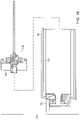
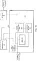
- FIG. 1illustrates a schematic illustration of a miniature endoscope system according to the invention
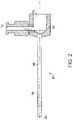
- FIG. 2is a cross-sectional view of cannula
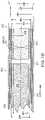
- FIG. 3is a cross-sectional view of a trocar within a cannula
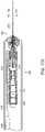
- FIG. 4is a perspective view of the miniature endoscope
- FIG. 5is a sectional view of the miniature endoscope with a cannula overlying the disposable sheath;
- FIG. 6Ais a sectional view of the disposable sheath/illuminator unit
- FIG. 6Bis an enlarged sectional view of the distal end to the disposable sheath
- FIG. 7Ais a sectional view of the proximal end of the disposable sheath/illumination unit taken along line 7 A- 7 A of FIG. 6A ;
- FIG. 7Bis a front view of the distal end of the disposable sheath taken along the line 7 B- 7 B of FIG. 6A and FIG. 6B ;
- FIG. 8is a side view of the disposable sheath/illumination unit showing the illumination pigtail
- FIG. 9is a sectional view of an imaging unit of the miniature endoscope.
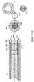
- FIG. 10Ais an enlarged view of the distal end of the imaging unit as indicated by the portion defined 10 A in FIG. 9 ;
- FIG. 10Bis a front view of the distal end of the imaging unit taken along the line 10 B- 10 B of FIG. 10A ;
- FIG. 11is a schematic of an enlarged partial sectional view of the imaging unit taken along the line 11 - 11 of FIG. 10A ;
- FIG. 12is an enlarged view of the distal lens system
- FIG. 13is a graph of the sine of the maximum ray angle versus normalized image height for different lens systems for the distal end of the endoscope
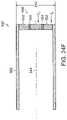
- FIG. 14is an enlarged view of another embodiment of a distal lens system
- FIG. 15is a sectional view of another embodiment of an endoscope
- FIG. 16Ais a sectional view of the endoscope taken along line 16 A- 16 A of FIG. 15 ;
- FIG. 16Bis a sectional view of the endoscope taken along line 16 B- 16 B of FIG. 15 ;
- FIG. 16Cis an enlarged sectional view of the imaging unit as indicated by the portion defined by 10 C in FIG. 16B ;
- FIGS. 16D-Lillustrate preferred embodiments of the invention
- FIGS. 16M-Pillustrate cross-sectional and end views of disposable components in accordance with the invention.
- FIG. 17Ais a sectional view of another embodiment of an endoscope
- FIG. 17Bis a sectional view of the endoscope taken along the line 17 B- 17 B of FIG. 17A ;
- FIG. 18is a side view of a two-part disposable sheath/illuminator unit
- FIG. 19is a schematic of a control unit for a preferred embodiment of the invention.
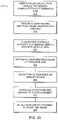
- FIG. 20illustrates a preferred method of using the invention
- FIG. 21illustrates a preferred embodiment of a portable endoscopic system in accordance with the invention
- FIG. 22Aillustrates a preferred embodiment of an endoscopic in accordance with the invention
- FIG. 22Billustrating a control system for another preferred embodiment of the invention
- FIG. 23is an end view of a sheath
- FIG. 24Ais a schematic view of a preferred endoscopic device
- FIG. 24Bis a cross-sectional view of the insertion portion of the probe.
- FIGS. 24C-24Iillustrate preferred embodiments of the endoscope system in accordance with the invention.
- FIG. 25is a schematic view of another preferred embodiment of an endoscopic device.
- FIG. 26illustrates a cross-sectional view of an illumination cannula in accordance with another preferred embodiment of the invention.
- FIG. 27illustrates a cross-sectional view of the cannula of FIG. 26 ;
- FIG. 28illustrates a method of using a labeled disposable kit in accordance with a preferred embodiment of the invention.
- FIG. 1An embodiment of the invention is illustrated in FIG. 1 that shows a miniature endoscope 20 .
- the endoscope 20has an imaging unit 22 and a sheath/illuminator unit 24 .
- the endoscope 20has an image transmission path such as a plurality of optical fibers 26 , as best seen at fibers 146 in FIGS. 11 and 12 , in an elongated tube 28 of a rod tip 29 used to view objects to be examined.
- the optical fibers 26are optically coupled to an imaging device 30 , such as a charged coupled device as seen in FIG. 9 , or other pixilated flat panel sensor, in a handle 32 .
- an imaging device 30such as a charged coupled device as seen in FIG. 9 , or other pixilated flat panel sensor
- a disposable sheath 34 of the sheath/illuminator unit 24overlies the elongated tube 28 of the rod tip 29 , which contains the optical fibers 26 .
- the proximal end of the disposable sheath 34has a base 35 with a mounting mechanism 36 for securing the sheath to the handle 32 .
- the disposable sheath 34 of the sheath/illuminator unit 24has a plurality of optical fibers for transmitting light to the distal end of the disposable sheath 34 and the distal probe 29 .
- the distal end of the disposable sheath/illuminator unit 24has a connection 38 to connect to a light source 40 .
- the handle 32can house a power input 41 , used to provide power to the endoscope 20 . It is recognized that the light source 40 and/or power source can be mounted within the handle 32 .
- the handle 32can also house an image output 42 .
- the image output 42provides a connection between an imaging device in the imaging unit 22 of the endoscope 20 and an electronic storage and/or display device.
- the storage deviceis a computer 44 , which is connected to a monitor 46 .
- a control unit 250is described in greater detail with respect to FIG. 19 .
- the sheath/illuminator unit 24has the disposable sheath 34 that is a sleeve assembly that is carried by the base 35 secured to the imaging unit 22 that overlies the elongated tube 28 to create a sterilized barrier.
- the sheath/illumination unit 24has a sterilized drape 52 which is mounted to the base 35 of the sheath/illuminator unit 24 and is positioned to overlie the remaining portion of the imaging unit 22 to provide a sterile environment.
- the endoscope 20needs to be positioned in the body to view the desired location.
- One such methodis to insert a cannula 60 into the body and thread the endoscope 20 through the cannula 60 .
- One method of inserting the cannula 60 into the body and then inserting the endoscope 20 into a body using the cannula 60is described below.
- a cannula 60such as seen in FIG. 2 , is first inserted into a site within a body.
- the cannula 60has a base 62 and a tube 64 .
- the tube 64has a shaft 66 which extends from the distal end 68 to a void 70 in the base 62 .
- the tube 64is made of a flexible material such as plastic or thin wall stainless steel.
- the cannula 60has a luer 72 for insertion of medications or fluids or for attachment to a suction device.
- a trocar 76For insertion of the cannula 60 into the body, a trocar 76 , as seen in FIG. 3 , is inserted into cannula 60 with a rigid shaft 78 of the trocar 76 received within the shaft 66 of the cannula 60 .
- the rigid shaft 78 of the trocar 76extends slightly beyond the distal end of the tube 64 of the cannula 60 and has a stylet 80 to cut into the tissue at the surgical site if necessary.
- the cannula 60 and trocar 76are of a relative minimal cost and can be reused after sterilization or disposed of after use, because of several components in the endoscope 20 such as components in the imaging unit 22 , it is not desirous to dispose of the entire endoscope 20 .
- the endoscope 20uses a disposable sleeve or sheath 34 to aid in maintaining a sterile environment and reduce or eliminate the sterilization requirements prior to reuse.
- the endoscope 20has the reusable imaging unit 22 and the disposable sheath/illuminator unit 24 .
- the disposable sheath/illuminator unit 24has a elongated tube for overlying and encircling the elongated tube 28 of the imaging unit 22 .
- the elongated tube of the sheath/illuminator unit 24has a sealed distal end 84 and several embodiments include fiber optics for transmitting the illumination from a external light source 40 , such as seen in FIG. 1 , to the distal end 84 .
- a base 35At the proximal end of the sheath/illuminator unit 24 is a base 35 with a mounting mechanism 36 for securing to the imaging unit 22 of the endoscope 20 .
- An optical pigtail 88projects from the base 35 for connecting to the light source 40 .
- the sheath/illuminator unit 24has a drape 52 which is mounted to the base 35 and is extended over the handle 32 of the imaging unit 22 .
- the handle 32 of the imaging unit 22contains optics and the imaging device 32 to receive the image transmitted through the optical fibers 26 located in the elongated tube 28 of the imaging unit 22 as described in further detail below with respect to FIGS. 9-11 .
- FIG. 5is a sectional view of the miniature endoscope 20 including the reusable imaging unit 22 with imaging an optical fiber 26 and the disposable sheath/illuminator unit 24 .
- the cannula 60is shown overlying the disposable sheath 34 of the sheath/illuminator unit 24 , which overlies the probe 29 of the imaging unit 22 .
- the reusable imaging unit 22 of the endoscope 20is encircled by the disposable sterile sheath/illuminator unit 24 .
- the disposable/sheath illuminator unit 24has the disposable sheath 34 that is sealed at the distal end 84 and encircles and surrounds the elongated tube 28 carrying the optical fibers 26 of the imaging unit 22 .
- the mounting mechanism 36 on the base 35 of the sheath/illuminator unit 24is secured to a mounting mechanism 92 on the imaging unit 22 .
- the disposable sheath/illuminator unit 24has the drape 52 which surrounds the handle of the imaging unit 22 .
- the sheath/illuminator unit 24has the illumination pigtail connecting to a light source 40 as seen in FIG. 1 .
- the illumination pigtail 88is optically coupled to the optical fibers in the sheath as explained in further detail below.
- the sheath unit 24has the disposable sheath 34 with an elongated outer sheath 98 which extends from the base 35 to the distal end 84 .
- the illuminator pigtail 88extends from the base and is optically coupled to illumination fibers 116 within the sheath 34 as seen in FIG. 7A .
- the drape 52is carried by the base 35 of the sheath/illuminator unit 24 for overlying the handle 35 of the imaging unit 22 when the two units 22 and 24 are combined.
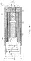
- FIG. 6Bis an enlarged view of the distal end 84 of the disposable sheath 34 of the sheath/illuminator unit 24 .
- the disposable sheath 34has the outer sheath 98 which extends from within the base 35 , as seen in FIG. 6A , and serves as protective covering and a sterile barrier for the sheath unit 24 .
- Spaced and collinear with the outer sheath 98is an inner tube 100 of the disposable sheath 34 .
- the inner tube 100defines a cylindrical void on space 102 for receiving the elongated tube 28 of the probe 29 of the imaging unit 22 .
- the inner tube 100likewise from the distal end 84 of the disposable sheath 34 to the base 35 of the sheath/illuminator unit 22 .
- the inner tube 100extends further than the outer sheath 98 to create a channel 106 to receive a plurality of illumination fibers 108 as best seen in FIGS. 6A and 7A .
- a window 110which is secured to the inner tube 100 to make a sterile 84 barrier between the airspace 102 for receiving the elongated tube 28 of the image unit 22 and the outer portion of the sheath/illuminator unit 24 which is in contact with the body.
- the outer sheath 98 of the disposable sheath 34 of the sheath/illuminator unit 24is made of a stainless steel material and has an outer diameter of about 0.038 inches.
- the inner tube 100is likewise made of a stainless steel material.
- the illumination fibers 108are made of a glass or plastic fiber. Depending on the size of the device, the maximum number of illumination fibers 108 is used to fill channel 106 .
- the disposable sheath 34extends 2.246 inches from the base 35 of the sheath/illuminator unit 24 .
- FIG. 7Ais a sectional view through the base 35 of the disposable sheath 24 .
- the outer sheath 98is shown in the lower half of FIG. 7A and terminates prior to the portion sectioned in the upper half of FIG. 7A .
- the inner tube 100which defines the airspace 102 to receive the elongated tube 28 of the imaging unit 22 extends to a receiving chamber 114 as seen in FIG. 6A and therefore is shown in both the upper and lower portions of FIG. 7A .
- the lightis transmitted from the illumination pigtail 88 through fibers 108 , as seen in FIG. 6A , to a transmission unit 118 as seen in the upper half of FIG. 7A which abuts the illumination fibers 108 located between the outer sheath 98 and the inner tube 100 of the disposable sheath 34 of the sheath/illuminator unit 24 .
- FIG. 7Bshows the distal end 84 of the disposable sheath/illumination unit 24 .
- the window 110overlies and seals the airspace 102 that receives the imaging unit 22 and is encircled by the inner tube 100 .
- Interposed between the outer sheath 98 and the inner tube 100is the plurality of illumination fibers 108 .
- the distal end of the illumination fibers 108are not protected and are exposed to the body.
- FIG. 8is similar to FIG. 6A in that it shows the disposable sheath/illumination unit 24 . In addition, FIG. 8 shows the entire illumination pigtail which is broken away in FIG. 6A .
- the illumination pigtail 88has a connection 38 for connecting to a connector on the light source 40 .
- the illumination pigtail 88has a plurality of optical fibers which run from the connection 38 to the fibers 108 which transmit the light received from the light source 40 to the transmission unit 118 shown in FIG. 7A and exit at 84 .
- the imaging unit 22has the probe 29 with the elongated tube 28 that extends from the handle 32 .
- the imaging deviceAt the proximal end of the handle 32 , is the imaging device.
- a charged coupled device (CCD) 30 Bwhich converts the optical image into an electrical image is carried in the detachable housing 120 A of the handle 32 .
- a plurality of lenses 122 AInterposed between the optical fiber or fibers 26 which extend in the elongated tube 28 and the CCD 30 B is a plurality of lenses 122 A for projecting the image of the proximal end 124 of the optical fiber or fibers 26 to the CCD 30 B.
- the glass window 122 Bis attached to housing 120 B and provides a seal to the scope. It also protects the lenses from contamination.
- the imaging unit 22enlarges the image from the end of the fiber optic 26 and couples it to the charged coupled device 30 B.
- the charged coupled deviceis connected to a electronic storage and/or display device such as a computer 44 which is connected to a monitor 46 as seen in FIG. 1 .
- the handle 32 of the imaging unit 22has a mounting mechanism 128 for coupling with the mounting mechanisms 36 of the sheath illuminator unit 24 .
- the mounting mechanism 128has slots 130 for receiving pins located on the mounting mechanisms 36 .
- the mounting mechanism 128has a projection 134 , from which the probe 29 projects, that is received by the receiving chamber 114 of the sheath/illuminator unit 24 as seen in FIG. 6A .
- FIG. 10AAn enlarged view of the distal end of the imaging unit 22 is shown in FIG. 10A .
- the rod tip 29 of the imaging unit 22has the elongated tube 28 that extends from the distal end 126 to the housing 120 of the handle 32 .
- a tube 138which extends a slight distance from the distal end 126 and just a slight distance beyond the ends of the optical or image fibers 26 .
- the tube 138is commonly referred to as the long tube in that a shorter and smaller diameter tube 140 which is collinear with the long tube 138 is received within the long tube 138 and extends a lens system 142 at the distal end 126 .
- the elongated or outer tube 128 , long tube 138 and small tube 140are mounted so that their distal ends are flush and are secured by an adhesive such as a medical grade epoxy.
- an adhesivesuch as a medical grade epoxy.
- the lens system 142At the end of the elongated tube 28 of the imaging unit 22 is the lens system 142 that is described in further detail below.
- the elongated tube 28 of the imaging unit 22is received within the disposable sheath/illumination unit 24 and therefore does not need to be sterilized prior to the first use.
- FIG. 10Bis an end-view of the distal end 126 of the imaging unit 22 .
- the lens system 142 , the small tube 140 , the long tube 138 and the outer or elongated tube 28are shown and are all collinear.
- FIG. 11a sectional view of the imaging unit 22 of the endoscope 20 is shown.
- the probe 29 of the imaging unit 22has a plurality of fibers 146 for transmitting the image from the distal end 126 of the rod tip 29 to the handle 32 .
- Encircling the fiber 146 at the distal end of the rod tip 29is the long tube 138 for holding the fibers 146 of the image fibers 26 in position.
- the outer or elongated tube 28encircles the long tube 138 and protects the fibers 146 of the image fibers 26 from their beginning near the distal end 126 of the rod tip 29 to the other end within the handle 32 .
- the fibersare arranged in a disorder pack method.
- This disorder pack methodlimits transmission of images/light from one lens 142 to another as the image fiber bundle 26 extends from near the distal end 126 of the imaging unit 22 towards the proximal end of the fibers located within the handle 32 .
- the disorder packing of fibersis achieved by varying the doping of the fibers, which is the subject area to be examined hereinafter.
- FIG. 12a sectional view of the distal end of the rod tip 29 of the imaging unit 22 within the disposable sheath 34 of the sheath/illuminating unit 24 is shown.
- the disposable sheath 34has the outer sheath 98 collinear with the inner tube 100 .
- the plurality of illumination fibers 108Interposed between the outer sheath 98 and the inner tube 100 is the plurality of illumination fibers 108 as best seen in FIG. 7B for illumination.
- the windowAt the distal end of the disposable sheath is the window that is secured, such as by cementing, to create a boundary to the air space or inner channel 102 that receives the rod tip 29 of the imaging unit 22 .
- the imaging unit 22has the elongated or outer tube 28 that extends from the distal end 126 to within the handle 32 as shown in FIG. 9 .
- a larger longer sleeve, referred to as the long tube 138encircles the tube 140 and the beginning of the fibers 146 of the image fibers 26 .
- the distal lens system 142 as shown in FIG. 12is an achromatic lens system having a pair of lenses 150 and 152 and an aperture stop 154 .
- the lenses 150 and 152each have a convex surface 156 that face each other.
- the second lens 152closer to the distal end 126 , has a planar surface 158 which abuts the optical aperture stop 154 .
- the aperture stop 154 and the lenses 150 and 152are designed so that the sine of the maximum ray angle approaches the fibers at N.A. (numerical aperture).
- the ray tracings 160 in FIG. 12illustrate the projection of an image off the page to the right at the proper focal length and how this image is translated through the aperture stop 154 and through the lenses 152 and 150 to the plurality of fibers 146 in the image fibers 26 .
- the lens systemis non-telecentric.
- FIG. 13a graph of the sign of the maximum ray angle versus the normalized image height for three different lens systems including a prior art lens system is shown.
- the graph in FIG. 13shows a line for the maximum sign of a ray angle for a 50 degree lens system and a second line for a maximum sign of ray angle of a 70 degree lens system.
- the maximum signis approximately 0.32. Therefore, the N.A. (numerical aperture) of the fiber is approximately the same.
- the 50 degree field of view systemhas a sign of a maximum ray angle of approximately 0.25. Therefore, the fibers have this numerical aperture.
- the systemcan provide a field of view at any selected level from 30-80 degrees, for example.
- the endoscope 20has 10,000 fiber elements.
- each fiber element 146has a diameter of 4.4 microns.
- the overall diameter of the fiber 26is 0.46.
- the elongated or outer tube 28 of the imaging unitis made from stainless steel. It is recognized, that the scope can be formed in many sizes, the following table is merely an illustration of various intervening size scopes.
- FIG. 14shows an alternative embodiment of the rod tip 29 of the imaging unit 22 of the endoscope 20 with a grin lens 168 .
- the grin lens 168 as shown in FIG. 14is a single element gradient index lens.
- the rod tip 29 of the image unit 22 as shown in FIG. 14has an elongated or outer tube 28 that extends from the distal end 126 to the handle 32 .
- a tube 138extends a slight distance from the distal end 126 .
- This tube 138is commonly referred to as the long tube, it extends just slightly beyond the ends of the optical image fibers 26 .
- the lens 170is a single lens there is no need for a small tube 140 for retaining the elements of a lens system.
- the grin lens 168in general does not provide preferred image quality as that of the acromat lens system 142 described above in that the image becomes less clear (i.e., blurry and distorted) towards the edge of the image.
- the color correctionchanges in intensity as a function of wavelength, is not as good as in the acromat lens system.
- the GRIN lens system 168maybe desirable in situations where cost is a higher factor than the overall image quality.
- the depth of fieldmay be limited. While only 2 different degrees of freedom are shown, it is recognized that lens systems with other fields of view can be made.
- FIG. 15is a sectional view of alternative endoscope 170 .
- the illuminator pigtail 172is a part of the handle 174 of the imaging unit 176 and is therefore not part of a disposable sheath/illuminator unit 178 .
- An optical fiber bundle 180is used for transmitting the illumination light from the pigtail 172 to a handle interface 182 in the handle 184 where the light is transferred to a light interface 184 on the sheath/illuminator unit 178 to transmit light from the handle 184 to the disposable sheath 186 .
- FIG. 16Ais a sectional view showing the interface.
- FIG. 16Ais a sectional view of the base 188 of the disposable/sheath illuminator unit 178 .
- the upper portion of FIG. 16Ashows the drape 52 spaced from the base 188 .
- the base 188has a light interface 184 that receives light from the handle interface 182 carried on the handle 174 .
- the sheath/illuminator unit 178has one of the illumination fibers 190 replaced by a tube or channel 192 .
- the tube 192which is seen in FIGS. 15 and 16A-16C is capable of receiving a laser fiber. The user passes a laser fiber though the tube 192 from the proximal end of the illumination unit 178 in the base 188 as seen in FIG. 15 , to the distal end of the illumination unit so that the user while viewing the image through the imaging fibers and CCD can complete a process using the laser fiber.
- FIG. 16Ashows a cross-sectional view through the base 188 of the sheath/illuminator unit 178 in which the tube 192 extending through the base into the annular ring containing the illumination fibers 190 . Similar to that shown in FIG. 7A , FIG. 16A shows an inner tube 194 around which the illumination fibers 190 are located. The inner tube 194 defines an airspace through which the probe 29 of the imaging unit 176 of the endoscope 170 passes.
- FIG. 16Bis a sectional view of the disposable sheath 186 showing an outer tube 196 of the disposable sheath 186 circling the illumination fibers 190 and the tube 192 .
- the inner tube 194surrounds the airspace 102 which receives the probe 29 of the imaging unit 176 .
- FIG. 16Cis an enlarged view showing the tube 192 with its opening to receive the laser fiber in the annular ray containing the illumination fibers 190 between the inner tube 194 and outer sheath 196 . While FIGS. 15-16C do not show a cannula 60 , it is recognized in most uses of the endoscope 20 or 170 , a cannula 60 can be used for extra protection of the endoscope 20 or 170 .
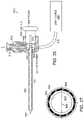
- FIG. 16 D-LIllustrated in FIG. 16 D-L is a disposable sheath and imaging assembly for a preferred embodiment of small diameter endoscope.
- FIG. 16Dshows the disposable sheath 300 including the tubular portion 304 for insertion into the body, a base or hub assembly 302 , which includes a sheath housing element 314 that is attached to the proximal end of tubular portion 304 , a cannula connector 312 that snaps onto a proximal connector of the cannula described above.
- the sterile barrier 306is attached to element 314 at the distal end of the barrier.
- the base 302further includes a connector assembly 305 that is attached to housing element 314 .
- the connector assemblycan include an optical coupler 310 that optically connects the illumination fiber bundle 316 to a light source when the imaging device assembly 340 , shown in FIG. 16E , is inserted into the sheath to provide the assembled endoscope 357 that is ready for use, as shown in FIG. 16F .
- the optical coupler 310is thus positioned within the sterile barrier 306 .
- the assembly 340includes a first connector 346 that connects to the optical coupler 310 that can plug into the connector 346 .
- a second connector 344 on assembly 340serves to mechanically attach the assembly 340 to a coupling element 308 positioned within connector assembly 305 .
- the usergrasps the handle portion 349 of element 340 and inserts the distal tip of tubular sheath 342 through the aperture 318 in the connector assembly at coupling element 308 , and through a proximal opening 311 in the proximal end of tubular sheath 304 .
- the first connector 346 and second connector 344engage the optical coupler 310 and coupling element 308 , respectively, substantially simultaneously.
- the optical couplingcan be inserted through an opening 335 in the distal surface 341 of handle 349 .
- the distal surfacecan be generally circular or oval in shape and have a diameter of 2-8 cm to easily fit within the hand of a user.
- the couplingcan use an o-ring 351 that fits within an o-ring groove 337 on the inside wall of opening 335 .
- the o-ring 351comes to rest in the o-ring groove 315 of coupler 310 to provide an optical coupler seal as shown in FIG. 16K .
- the proximal face of coupler 310can comprise the polished proximal end of optical fiber bundle 316 which receives light through sealed window 343 from light source 348 which can be an LED or laser diode.
- light source 348which can be an LED or laser diode.
- white light LEDs suitable for imaging for many applications of the present inventionare available from the American Opto Plus LED Corp., Pomona, Calif.
- Two or more different light sources having white, broadband or monochromatic emission spectracan be coupled to different optical fibers of bundle 316 so that the user can selectively illuminate a region of interest with different wavelengths or bands of light for imaging and/or spectroscopic analysis.
- the light source 348can be powered by batteries 350 which can be inserted into the handle 349 by removing cap 345 .
- Imaging device 352can be a CCD or CMOS imaging sensor within electronics module 354 which can include processing, control and wired or wireless connection as described elsewhere herein.
- the optical relay described previouslyis located in optical housing 347 to couple light from the imaging channel to camera 352 .
- the o-ring 332 on connector 344fits within groove 307 after the tube 342 is inserted along axis 309 through openings 318 and 311 to provide an optical relay seal.
- coupler 310provides a first fluid tight seal to the handle and coupling element 308 provides a second fluid tight seal to the handle.
- the distal end 360 of tubular sheath 304is shown in enlarged partial cross-sectional and end views of FIGS. 16G and 16H , respectively.
- the sheathcan include an outer tube 362 , inner tube 364 co-axially mounted thereto about longitudinal axis 363 , optical fibers 365 that fit within the cylindrical cavity between the outer and inner tubes.
- the fibers 365have a packing factor of at least 80%, and preferably over 85%, in order to provide good coupling and distribution of light from the light source 348 across a large field of view.
- An adhesive 366is used to bond the distal ends of the fibers together and to the inner and outer tubes.
- the adhesivecan be applied to the portion of the fibers extending out of cylindrical cavity between the inner and outer tubes, then the fibers are gently pulled in the proximal direction so that the adhesive covered walls of the fibers are pulled between the inner and outer tubes for at least 2 mm.
- the distal ends of the fibersare cut and polished to provide a single optical illumination surface.
- the ratio of area occupied by the distal illumination area I A , formed by the area occupied by the distal ends of the illumination fibers 365 , to the area of the window 370 , or light collection area C A , through which the image is collectedbecomes an important metric in defining the imaging characteristics of small diameter endoscopes of less than 3 mm in diameter. Generally, the smaller the device, the more critical this ratio becomes.
- the packing factor of the optical fiberscan be increased, thus providing more efficient use of the illumination area.
- the individual fibersshown in the quadrants 371 , extend completely around the circumference, and can have from one to ten rows of fibers, for example.
- Optical fibers having diameters of 30 microns to 50 micronscan be used, for example, to more fully use the available volume.
- 30 micron optical fiberbetween 500 and 1000 optical fibers can be used depending on the size of the cylindrical volume between the inner tube 364 and the outer tube 362 .
- the outer diameter 361 of outer tube 362is 1.7 mm and the inner diameter 369 of outer tube 362 is 1.45 mm.
- the inner tube 364has an outer diameter 368 of 1.17 mm and an inner diameter 367 of 1.072 mm.
- the windowhas a diameter of about 1.07 mm and an area of about 0.9 mm 2 .
- the ratio I A /C Ais about 0.64.
- the ratiois preferably between 0.5 and 1.0 but can be as high as 2.0 for certain applications.
- FIG. 16MShown in FIG. 16M is a cross sectional view of a sheath 390 during manufacture in which the ends of illumination fibers 391 are bent of splayed. After application of the adhesive to attach the fibers to the tubes of the sheath 390 , the distal ends of the fibers are cut off and the surfaces 393 polished. Instead of a circular end, however, the distal end 392 of each fiber has a somewhat oval or noncircular shape 394 , as seen in FIG. 16N , that alters the angle at which light exits the fiber and can increase the filed of view by 5-10 degrees.
- a prism 396can be added as shown in FIG. 16O .
- the prism 396can shift the field of view by 1-10 degrees, for example.
- a prism with a face angled at 10-30 degreescan be inserted and attached to the inner tube of the sheath with an adhesive layer to provide side viewing at a greater oblique angle.
- the prismcan be attached to the distal end of the imaging channel and a sheath having an angled window conforming to the shape of the prism which can be used with a lens or prism mounted on the distal end of the illumination fibers, or the distal ends of the fibers can be angled within the sheath to provide the desired illumination area at the desired angle.
- FIG. 16Pshows the prism 396 and the surrounding illumination fibers 397 which have a small diameter, preferably in a range of 30-50 microns, so as to reduce the interstitial spacing 398 between the adjacent fibers to provide the desired packing factor of at least 80%.
- FIG. 17Aa sectional view of an alternative endoscope 200 is shown.
- the endoscope 200has an imaging unit 202 and a sheath unit 204 .
- the sheath 204 that is disposabledoes not include any part of the illumination unit.
- the illumination source 40is connected to the handle 206 of the imaging unit 202 by an illumination pigtail 208 similar to that shown in FIG. 15 . But in contrast, there is no coupling such that the light is transmitted to the disposable sheath 204 . Rather, as seen in FIG. 17A , the illuminator pigtail 208 is a part of the handle 206 of the imaging unit 202 .
- An optical fiber 210is used for transmitting the illumination light from the pigtail 208 to an interface 212 in the handle 206 .
- the interface 212is located within the handle 206 and transfer the light to an annular ring 214 of a plurality of illumination fiber 216 .
- the probe 218has an outer tube 220 and an inner tube 222 . Interposed between the tubes 220 and 222 is the annular space for receiving the plurality of illumination fibers 216 . Located in the inner tube 222 , which is similar to the elongated tube 28 in the first embodiment, is the image fiber bundle 26 . The fiber bundle 26 is spaced from the inner tube 222 . A long tube 224 , which extends for a slight distance from the distal end 126 to just beyond the ends of the image fiber bundle 26 , is interposed between the fibers 26 and the inner tube 222 .
- the sheath 204has a single outer layer 226 .
- a window curved to avoid retroreflectionis secured to the distal end of the single outer layer 226 .
- a two piece disposable sheath/illuminator unit 230is shown.
- the endoscopehas a first unit 232 of the two piece disposable sheath/illumination unit 230 , a mounting and cover unit 232 , that is mounted to the handle 32 of the imaging unit 22 .
- the mounting and cover unit 232has a drape 52 that extends over the handle 32 of the imaging unit 22 and the illumination pigtail 88 when used.
- the drape 52is retained on a disposable sleeve 234 to hold the drape 52 until positioned over the handle 32 .
- the second unit 236 of the disposable sheath/illumination unit 230 , a disposable sheath 236contains the elongated tube that covers the probe 29 .
- This second unit 236has a mounting mechanism 238 to secure to the first unit 232 . It is therefore possible to remove the disposable sheath, the second unit, 236 and replace it with a new one while keeping the drape 52 that is mounted to the mounting and cover unit 232 over the handle.
- FIG. 19is a schematic of a control unit 250 for the endoscope.
- This control unit 250has a power source output 252 , an input 254 for the image from the CCD and a light source 256 .
- the unithas a recording device 258 such as a CD writer to create a storable medium to retain data such as a baseline for the patient.
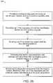
- the endoscopeis used as shown generally in the process sequence 270 of FIG. 20 .
- the patientcomes to the user/physician's office.
- the physician or technicianuses a double gloved technique where two sterilized gloves are placed on each of the physician's hands.
- the physiciantakes the handle/illuminator unit which is not sterilized in one hand and secure the sterilized sheath/illuminator unit with the other hand.
- the physicianthen takes the lighting cord and secures the light cord to the pigtail on the disposable sheath/illuminator unit.
- the power and image outputare likewise connected to the control unit.
- the drape portion of the sheath assemblyis extended 272 over the handle and down the cords to such a length to provide a sterile field.
- the physiciantakes off the first pair of gloves and is ready to begin the procedure.
- the cannula with the trocaris inserted into the body by a standard technique of probing with the physician's hand.
- the trocaris removed 274 and the tip of the endoscope is placed into the cannula.
- the endoscopeis secured to the cannula using a screw or other attachment mechanism.
- the systemis actuated 276 and video recording is initiated so that the physician is able to move the cannula in and out and around to position the probe for viewing of the desired site or as a monitor.
- the physiciancan perform a procedure 278 at the site using other instruments such as a laser scalpel or cautery tool, or electrosurgical tool and/or the operative channel in the probe or sheath assembly.
- the entire examination or operative procedurecan be recorded 280 on a video disk or other memory device.
- the procedureis concluded and the sheath assembly can be disposed 282 of and another sterile sheath assembly can be attached 284 to the probe for another procedure.
- a preferred embodimentprovides multi spectral imaging capability.
- This embodimentincludes the use of a light source and a detector to provide images over the wavelength range of 700 nm-1200 nm. This allows the user to see through blood to observe tissue.
- UVultraviolet
- Another embodimentuses the ultraviolet (UV) region of the electromagnetic spectrum (10 nm-380 nm) to be able to treat tissue.
- Ultraviolet lightin the range of 325-250 nm can pull together and cauterize.
- Lasers or conventional broadband light sourcescan be used to provide light to the illumination system.
- the imaging fiber bundlecan also be used for illumination with a beam splitter in the handle to couple light from one or more sources individually or simultaneously to the fiber bundle.
- Embodiments of the inventioncan be employed in office-based settings for performing diagnostic imaging of interior surfaces of a body.
- Office-basedrefers to locations other than essentially sterile environments such as, by way of example, hospital operating rooms, hospital procedure rooms, rooms proximate to sterilization means such as autoclaves, and the like. Examples of office locations are, but are not limited to, examination rooms at a physician's office, training rooms adjacent to locker rooms in sporting complexes, ambulances, residences, field hospitals, hospital corridors, examination rooms, emergency rooms, office buildings, stores, and the like.
- the miniature endoscope 20operates as a fluidless system, although fluid can be used if desired.
- a fluidless systemrefers to the fact that no liquid media, irrigation or distention fluid (e.g., saline solution) has to be injected into a patient's body in the vicinity of the target area, i.e. the area that will be viewed using the invention.
- the miniature endoscopecan simply be inserted through a patient's skin, and used to view a target area without requiring additional instruments, injection means, consumable substances and without generating excess hazardous waste, other than the disposable portion, such as would be generated if irrigation fluids were injected into and removed from the target area.
- the disposable portion 20may comprise a disposable needle covering employing a transparent window in its distal end.
- the transparent windowprevents fluids from a patient's body from coming into contact with non-disposable portions (e.g., 32) of the system.
- Nondisposable portions operating in conjunction with the disposable portion 20may include a thin shaft which slides inside the introducer and contains a fiber optic illumination system for conducting images of the target area to a miniature camera located in a handle 32 .
- the fiber optic illumination systemmay comprise a protective window and high resolution fiber optics and lens transmission means for conveying images to the camera.
- the disposable portionmay also include a slide port for introduction of surgical instruments or for evacuation of fluids by suction or for introduction of medications to the target area.
- FIG. 21illustrates exemplary embodiments of a portable endoscopic system 291 comprising, among other things, miniature endoscope 20 , handle 32 , imaging unit 22 , cable 290 and laptop 292 .
- the endoscopic unit and imaging unit 22are connected directly to laptop 292 by way of cable 290 .
- imaging unit 22may output a video signal that is sent to a video in jack on laptop 292 .
- Laptop 292is then used to enter patient information, session details, and is used to display real-time image data as the procedure is carried out.
- PCMCIApersonal computer memory card international association
- PCMCIA cardmay be an industry standard card as known in the art, or it may be specially adapted for use with the miniature endoscope.
- a specially adapted PCMCIA cardmay include hardware for receiving and processing video signals received from the imaging unit.
- the output of PCMCIA card 294may be an industry standard data format for conveying processed image data to a display associated with the laptop.
- a portable endoscopic system 291that includes imaging unit or an interface box 32 and an interface box cable 290 for conveying data to laptop 292 .
- Interface boxmay include more sophisticated imaging, image processing, and data communication hardware and/or software than can be employed in PCMCIA card 294 or directly inside laptop 292 .
- the interface box 296may be configured to perform real-time image enhancement on data received through the distal end of miniature endoscope 20 .
- Image enhancementmay be used to produce images suitable for performing diagnostics while making use of less costly components in miniature endoscope 20 .
- a GRIN lensmay be employed in miniature endoscope 20 to provide image data to the interface box.
- the interface boxmay employ image processing algorithms for enhancing the image quality produced by the edges of GRIN lenses.
- Interface boxmay then convey image data to laptop 292 in an industry standard format by way of cable.
- the systemcan also include mounting on a cart 298 for transport, as display 295 and a light source system 296 .
- the systemcan include a standard lamp for visible light imaging as well as infrared or ultraviolet light sources for imaging or treatment.
- a generalized architecturecan be used including a central processing unit (CPU), which is typically comprised of a microprocessor associated with random access memory (RAM) and read-only memory (ROM). Often, the CPU is also provided with cache memory and programmable FlashROM.
- the interface between the microprocessor and the various types of CPU memoryis often referred to as a local bus, but also may be a more generic or industry standard bus.
- CPUprocesses and interprets machine-readable, or function-executable, instructions associated with an operating system, user-developed applications, diagnostic tools, patient data hospital servers, health provider computers, and computers associated with remote experts.
- GUIgraphical user interface
- HDDhard-disk drives
- CD-Rcompact disc drives
- CD-RWcompact disc drives
- DVD-RDVD-R
- proprietary disk and tape drivese.g., Iomega ZipTM and JazTM, etc.
- storage drivesmay be accessible over a computer network such as network-based storage system.
- the RAMis capable of storing machine-readable instructions and information necessary to operate software applications for processing and displaying image data received from miniature endoscope.
- a personal computer, laptop, or belt-wearable computeris often provided with a high speed serial port (RS-232, RS-422, etc.), an enhanced parallel port (EPP), and one or more universal serial bus (USB) ports.
- the computing platformmay also be provided with a local area network (LAN) interface, such as an Ethernet card, and other high-speed interfaces such as the High Performance Serial Bus IEEE-1394.
- LANlocal area network
- Computing platformssuch as wireless telephones and wireless networked PDA's may also be provided with a radio frequency (RF) interface with antenna, as well.
- RFradio frequency
- the computing platformmay also be provided with an infrared data arrangement (IrDA) interface.
- IrDAinfrared data arrangement
- ISAIndustry Standard Architecture
- EISAEnhanced Industry Standard Architecture
- PCIPeripheral Component Interconnect
- PCMCIAPersonal Computer Memory Card International Association
- proprietary interface slotsfor the addition of other hardware, such as sound cards, memory boards, and graphics accelerators.
- many unitssuch as laptop computers and PDA's, are provided with one or more external expansion slots allowing the user the ability to easily install and remove hardware expansion devices, such as PCMCIA cards, SmartMedia cards, and various proprietary modules such as removable hard drives, CD drives, and floppy drives.
- hardware expansion devicessuch as PCMCIA cards, SmartMedia cards, and various proprietary modules such as removable hard drives, CD drives, and floppy drives.
- the storage drives, communication interfaces, internal expansion slots and external expansion slotsare interconnected with the CPU via a standard or industry open bus architecture, such as ISA, EISA, or PCI.
- a computing platformis usually provided with one or more user input devices, such as a keyboard or a keypad, and mouse or pointer device, and/or a touch-screen display.
- user input devicessuch as a keyboard or a keypad, and mouse or pointer device, and/or a touch-screen display.
- a full size keyboardis often provided along with a mouse or pointer device, such as a track ball or TrackPointTM.
- a simple keypadmay be provided with one or more function-specific keys.
- a touch-screenis usually provided, often with handwriting recognition capabilities, and in the case of a laptop, a small keyboard and touch-sensitive display may be provided.
- a microphonesuch as the microphone of a web-enabled wireless telephone or the microphone of a personal computer, is supplied with the computing platform.
- This microphonemay be used for entering user choices, such as voice navigation of web sites, user menus associated with operating miniature endoscope 20 , conveying data to remote locations, or auto-dialing telephone numbers.
- Voice recognition capabilitiesnormally in the form of software may be employed for facilitating speech based interaction with the computer.
- Many computing platformsare also equipped with a camera device, such as a still digital camera or full motion video digital camera which can be used for facilitating collaboration between the person performing the endoscopic procedure and a remote expert that may be guiding the procedure and interpreting results in essentially real-time by way of a networked display device.
- a camera devicesuch as a still digital camera or full motion video digital camera which can be used for facilitating collaboration between the person performing the endoscopic procedure and a remote expert that may be guiding the procedure and interpreting results in essentially real-time by way of a networked display device.
- the displaymay take many forms, including a Cathode Ray Tube (CRT), a Thin Film Transistor (TFT) array, a simple set of light emitting diodes (LED), liquid crystal display (LCD) indicators, a heads-up (i.e. hands free) display, or a projection display.
- CTRCathode Ray Tube
- TFTThin Film Transistor
- LEDsimple set of light emitting diodes
- LCDliquid crystal display
- heads-upi.e. hands free
- One or more speakers and/or annunciatorsare often associated with computing platforms, too.
- the speakersmay be used to reproduce audio instructions.
- Annuciatorsmay take the form of simple beep emitters or buzzers, commonly found on certain devices such as PDAs and PIMs. Annunciators may be used to alert the operator of system that an error has occurred.
- These user input and output devicesmay be directly interconnected to the CPU via a proprietary bus structure and/or interfaces, or they may be interconnected through one or more industry open buses such as ISA, EISA, PCI, etc.
- the computing platformis also provided with one or more software and firmware programs to implement the desired functionality of the computing platforms.
- OSoperating system
- portable or device-independent programsmay be provided, which must be interpreted by an OS-native platform-specific interpreter, such as JavaTM scripts and programs.
- computing platformsare also provided with a form of web browser or micro-browser, which may also include one or more extensions to the browser such as browser plug-ins and configured to facilitate transmission and reception of image data over network.
- the computing deviceis often provided with an operating system, such as Microsoft WindowsTM, UNIX®, IBM OS/2TM, or AIX®, LINUX, MAC OSTM, Sun SolarisTM, or other platform specific operating systems.
- an operating systemsuch as Microsoft WindowsTM, UNIX®, IBM OS/2TM, or AIX®, LINUX, MAC OSTM, Sun SolarisTM, or other platform specific operating systems.
- Smaller devicessuch as PDA's and wireless telephones may be equipped with other forms of operating systems such as real-time operating systems (RTOS) or Palm Computing's PalmOSTM.
- RTOSreal-time operating systems
- Palm Computing's PalmOSTMPalm Computing's PalmOSTM.
- a set of basic input and output functions (BIOS) and hardware device drivers 356are often provided to allow the operating system and programs to interface to and control the specific hardware functions provided with the computing platform.
- one or more embedded firmware programs 358are commonly provided with many computing platforms, which are executed by onboard or “embedded” microprocessors as part of the peripheral device, such as a microcontroller or a hard drive, a communication processor, network interface card, or sound or graphics card.
- An exemplary systemuses portable system operating in conjunction with a network.
- a doctor's officecontaining portable system, a network, a health insurance provider having data storage associated therewith, a hospital server having data storage, a remote expert computer and a network-based storage system.
- the doctor's officeemploys a portable system for performing diagnostic evaluations of one or more patients.
- Image data obtained from a sessionmay be stored on the laptop memory and conveyed to one or more remote locations by way of a network.
- the networkmay be any type of network running any kind of network protocol.
- the networkmay be an intranet such as a local area network (LAN) operating within a corporate location or university campus, a metropolitan area network (MAN) operating within a geographic region such as a city and its surrounding suburbs, or a wide area network (WAN) such as the world wide web.
- LANlocal area network
- MANmetropolitan area network
- WANwide area network
- the networkmay run any type of networking protocol such as, for example, transmission control protocol and Internet protocol (TCP/IP), asynchronous transfer mode (ATM), synchronous optical network (Sonet), frame relay, integrated services digital network (ISDN), open shortest path first (OSPF), etc.
- the networkmay employ a plurality of links for coupling network elements and locations. Links may be comprised of hardwired links and/or wireless links. Examples of hardwired links are, but are not limited to, coaxial cable, twisted pair cable, optical fibers, etc.; and examples of wireless links are, but are not limited to, radio frequency (RF) such as IEEE 802.11 based links, or free space optical links.
- the networkmay also comprise gateways and/or firewalls for providing access to the network and for providing protection against undesirable network traffic such as denial-of-service attacks as well as network traffic containing malicious code such as computer worms and viruses.
- Data conveyed from the portable system to the networkmay be directed to a health insurance provider.
- the health insurance providermay archive received data on data storage by way of link for future use.
- the health insurance providermay employ its own experts, alone or in combination with automated analysis systems, to review data obtained during an endoscopic procedure using the invention.
- a portable systemmay also convey data to a hospital server.
- the hospital servermay further include data storage coupled thereto by link.
- Hospital servermay serve as a pooling resource for maintaining data associated with patients having an affiliation therewith.
- Data obtained using portable systemmay further be sent to a remote expert computer by way of network.
- a remote expertusing remote expert computer, may review image data post mortem or in quasi-real-time.
- the remote expertmay provide a second opinion prior to scheduling more invasive procedures or the remote expert may provide the primary diagnosis in situations where a skilled operator is performing the procedure with miniature endoscope 20 .
- disaster relief personnelmay be on scene at a remote location and performing a diagnostic procedure on a disaster victim.
- a remote expertmay be viewing image data received over a free space satellite network in real-time to direct the on-scene personnel with respect to the diagnostic procedure.
- the remote expertmay then direct an on-scene person to mark an insertion location on a victim/patient, to introduce the needle covering, to maneuver the endoscope 20 , and then may use real-time data to recommend accurate treatment for the victim without having to be on site.
- Data from the portable systemmay further be conveyed to a network-based storage system.
- the network-based storage systemmay serve as secure and redundant storage for image data resident on laptop.
- the network-based storage systemmay serve to keep image data in a location that is more readily accessed for replay than if the data were kept solely on laptop.
- the system and other remote entitiesmay be communicated with using portable system without departing from the spirit of the invention.
- a preferred method for using the miniature endoscope 20 in conjunction with portable systeminvolves performing diagnostic procedures.
- the systemcan be transported by cart into an examination room or other site where the procedure will be performed.
- a camerais coupled to the viewing system.
- an insertion siteis prepared on a patient's body. Preparation of the insertion site may include, among other things, marking the site using a medically approved writing instrument, and cleansing the area with an antiseptic solution, etc.
- a disposable needle coveringmay be coupled to the imaging and viewing system. As previously discussed herein, only disposable portions of miniature endoscope 20 contact the patient so no special sterilization processes need be applied on site. The needle covering of miniature endoscope 20 is then inserted into a target area of a patient.
- the imaging and viewing systemmay be activated. Image data is viewed and recorded using laptop during the diagnostic procedure.
- the needleis withdrawn from the target area. After needle withdrawal, the insertion location may be dressed using sutures, liquid adhesives approved for topical wound dressing, butterfly closures, or conventional small wound dressings such as gauze or bandages.
- Recorded image datacan be reviewed by the diagnostician and shown to the patient in the procedure room. After review, recorded data can be archived locally on a laptop, on removable storage media, or by way of network-based storage system.
- image data long with alphanumeric and/or voice annotationsmay be sent to one or more remote locations using network. Then the portable system may be returned to its storage location, and the patient immediately discharged after the procedure, since no complex anesthesia was required.
- the portable systemmay be deployed in a distributed architecture where the user is located at a first geographic location, with a patient and the miniature endoscope comprising elements 20 , 21 and 22 while the laptop display is located a distance away and is coupled to the miniature endoscope by way of a wireless network.
- the inventionmay be deployed in a ruggedized configuration for use in battlefield triage and/or for responding to disasters in remote and rugged locations.
- the portable endoscopic systemmay be integrated into mechanized conveyances such as trains, ambulances, air planes, ships, vehicles, etc.
- images generated using the portable endoscopic systemmay be replayed and used for training purposes.
- the portable endoscopic systemmay comprise a belt-wearable computer having a short range high bandwidth link to handle for receiving image data.
- handlemay comprise a self-contained power source such as a rechargeable battery.
- This embodimentmay further utilize a heads-up display worn on a user's head. Such a configuration provides the user with maximum mobility and minimum weight.
- the belt-wearable embodimentmay further communicate with network by way of a wireless link.
- the laptopcan be replaced with a customized processing device that can take on essentially any form factor and user interface configuration.
- a customized processing devicethat can take on essentially any form factor and user interface configuration.
- the customized processing devicemay gather image data and store it for later review or it may automatically transmit data to a remote location using a wireless RF or free space optical link.
- FIG. 22Aillustrates another preferred embodiment of a portable endoscope 400 in accordance with the invention including a handle 402 having a camera module 404 , an optical coupler 406 , a processor 408 , a wireless communications module 410 , a wireless antenna 412 , a battery 414 and a power regulator 416 .
- a light source 418within handle 402 .
- the light source 418preferably comprises an LED assembly such as an EOSTM LED fiber optic illuminator available from Edmund Optics, Barrington, N.J.
- the light sourcecan also comprise one or more laser diodes or a combination of laser diodes and LEDs, a laser or laser diode in the ultraviolet portion of the spectrum can be used to induce fluorescence in tissue for diagnostic purposes or for cautery.
- the handlecan have a control panel 409 with buttons that the user employs to electrically operate the handle.
- the camera 404can be a CCD or CMOS imaging sensor such as the TC7040 two megapixel CMOS imaging sensor device available from TransChip Israel Research Center, Ltd. This device includes a 1600 ⁇ 1200 pixel color sensor array that is packaged with a clock, controller, image processor and local SRAM memory in a single chip package.
- the camerapreferably has sensitivity in the infrared portion of the spectrum (750-1000 nm) as well as the visible.
- an infrared imaging sensorthat can detect light in the range of 1500 nm to 1900 nm, for example, as this improves imaging of tissue through blood.
- An infrared light source as well as spectral or cutoff filters 407 for the detectormay be needed for certain spectral imaging applications.
- the disposable 420 as described previously hereinhas a port 422 for coupling light from the light source into the fiber optic illumination bundle within the coupler 424 of the disposable.
- the distal end of the sheathcan have a cutting element 425 that can be recessed during insertion and imaging and mechanically actuated by wire or other means to cut a tissue sample from a region of interest within the body.
- the handle 402can also include a bar code reader 442 or other device that uniquely identifies the disposable component being attached thereto.
- the bar code 440can be imprinted on the proximal end of the disposable coupler 424 shown in FIG. 23 .
- This bar codecan have a radial or rectangular array. A radial array can be scanned past the reader 442 while the coupler 424 rotates into the locked position with the handle 402 .
- some other electronic identifying and recording devicesuch as a radio frequency identification (RFID) system can be used or a chip with a serial number can be in the disposable. This can be used for safety and record/inventory purposes.
- RFIDradio frequency identification
- one or more disposable componentscan be inserted into a bag, container or package having a machine readable element or code as described above.
- This machine readable elementuniquely identifies the disposable or disposable kit that is contained within the package.
- This kitcan include the disposable sheath, the cannula and the trocar as described in connection with the various embodiments of the present invention.
- the machine readable package or container 482is scanned by a scanner such as a bar code sensor that is connected to the system computer which then records 484 the specific disposable package or kit and enables 486 operation of the system. After the disposable is attached and used 488 to obtain images, the disposable is detached and disposed of for safety.
- the system computeris programmed with a software program that requires a new package code to be scanned before enabling the system to operate further.
- the wireless moduleprovides for delivery of video from the handle to a receiver in communication with a desktop or laptop computer.
- a cable 405can also optionally be connected to the handle 402 to provide a connection to the computer and associated display.
- a display 450can also be integrated directly into the handle 402 for viewing by the user.
- the video or still images taken with the cameracan also be recorded onto removable media such as a compact flash card, CD, DVD, mini DVD or SD card. Compact media can be inserted into a slot in the handle 402 .
- a beam splitter within the handlecan be used for this purpose as described previously.
- the handle 402can also be configured to dock with a base unit 460 that can transmit and receive images and data from the processor 408 with a transceiver 462 .
- the base 460can also be used as a recharger for the battery 414 and can include a communications circuit for a network or internet connection, a facsimile device or standard telephone data connection.
- the endoscope 400can interface with a system 470 such as that shown in FIG. 22B .
- the connection 479 with the endoscopecan be wired or wireless.
- a wireless transmitter/receiver 471is connected to processor 472 that is programmed to provide control signals to the endoscope 400 .
- the processorreceives image data that can be stored in memory 492 or printed or electronically copies with device 494 .
- a display device 474such as those provided by Motion Computing, Inc., of Austin, Tex., with display 495 can be integrated with unit 470 or can be in wireless communication with unit 470 or other network using transmitter receiver 475 .
- Device 474can also dock with system 470 using connectors 473 , 478 .
- Device 474can be powered by battery 476 and can also include a sensor 477 that can be used to identify a patient, a disposable sheath or other machine readable data.
- Sensor 477can be a bar code reader or other identification sensor as described previously herein.
- the system shown in FIGS. 22A and 22Bcan be implemented in a portable design having a weight of 10 pounds or less.
- the disposablecan also include a lens at the distal end, or a prism or mirror for side-viewing applications.
- the disposablecan have a length of between 20 mm and 2500 mm depending on the application. For small joints or bones such as the hand or foot smaller lengths in the range of 20 mm to 800 mm are used. For the knee and shoulder lengths in the range of 800 mm to 1500 mm can be used for applications such as the hip, longer lengths from 1500 mm up to 2500 mm may be used.
- imaging applicationssuch as the breast or brain, imaging in the visible portion of the spectrum can be supplemented by imaging in the near infrared or infrared portions of the spectrum. This can be used to supplement mammographic screening.
- imaging and diagnostic applicationsinclude ovarian cancer diagnostic imaging and spectral diagnosis, endometriosis, pre-natal diagnostic imaging, prolapse or fibroid imaging and treatment, and urinary tract diagnostics.
- the systemcan also be used for upper respiratory applications including the ear, nose and throat.
- These embodimentscan employ a flexible probe in which polymeric tubes are used to house the distal imaging channel assembly and form the tubular wall of the disposable sheath.
- a biopsycan also be used to collect a tissue sample, if needed.
- Dyes or tissue autofluorescencecan also be used with a narrowband light source such as a laser diode emitting at a wavelength in a range of 300 nm to 500 nm, for example.
- Gallium nitride diode laserscan be used for this purpose.
- FIG. 24Ashows a preferred embodiment in which the illumination fibers 502 are rigidly attached to the handle 500 .
- the disposable 510is connected with connector 512 to the handle and can include a lens 520 or a mirror or prism 540 for angled or side viewing.
- a cross-sectional side view of such an embodimentis illustrated in FIG. 24B which is also seen in the sectional view of FIG. 17B .
- This embodimentemploys a distal window 560 on the end of the disposable sheath 204 that has a fluid tight seal to the sheath.
- the windowhas an outer transparent element or illumination window 562 that transmits the illuminating light from the fibers 216 in a distal direction as shown by light rays 217 , 219 .
- the window 560can have a separate inner element or light collection window 564 which receives light returning from the illuminated region of interest.
- the outer and inner window elementsare optically decoupled by a light barrier 566 that can be a stainless steel spacer that is attached to both the outer and inner elements 562 , 564 using an adhesive, for example.
- the imaging fibers 26receive light collected through element 564 and focused by lens system 225 onto the imaging fibers generally along longitudinal axis 565 .
- FIGS. 24C-24Eare cross-sectional view of a preferred embodiment of a small diameter endoscope including a disposable sheath 600 and an imaging and illumination assembly 620 .
- the disposable sheath 600 shown in FIG. 24Cdoes not incorporate the illumination channel, but rather has a thin walled tube 602 scaled at the distal end with a window assembly described herein.
- the tube 602is attached at its proximal end to a hub 604 that includes a cannula connector 606 mounted on a sheath housing element 605 .
- a sheath connector 610is attached to the proximal side of housing element 605 and the sterile barrier 608 is attached to the outer wall of housing element 605 .
- the sheath connector 610includes an o-ring groove 612 such that upon insertion of the imaging and illumination assembly 620 into the sheath 600 , an o-ring 626 on a mating connector 624 will “snap” into the connector 610 .
- the distal end of tube 622is inserted through the central opening in the connector 610 and into the proximal opening 614 of tube 602 .
- the distal surface 629 of the distal hub 621 on handle 625can butt against the proximal surface 607 of element 605 . In this embodiment, as shown in FIG.
- the fiber optic illumination bundle 628extends through the distal hub 621 to the optical coupler 627 that is optically coupled to the light source without the need for a window to seal the light source as in the embodiment of FIG. 16E .
- the embodiment of FIG. 24Dcan have handle components identical to those in FIG. 16E except as described above. The assembled unit shown in FIG. 24E is ready for use.
- the distal end 640 of tube 602 of the sheath 600is shown in the embodiment of FIG. 24F .
- the outer diameter 642is 3 mm or less with a preferred embodiment of 2 mm or less.
- Particular examples of the sheathhave outer diameters of 1.7 mm and 1.2 mm. Smaller diameters are important for minimizing discomfort to the patient in many applications.
- the distal end 640is sealed with window assembly 648 .
- the window assembly 648can include a light collection window 650 with a light collection area C A and an illumination window 652 with an illumination area I A that extends circumferentially around window 650 .
- An opaque adhesive layer or tube element 654that is held in place with an adhesive forms a light barrier between the outer window 652 and central window 650 .
- the window 650is aligned along the optical axis 644 of the disposable sheath 600 .
- the window assembly 648can be replaced by a prism assembly to provide angled viewing.
- a prism assemblycan be mounted on the distal end of assembly 620 that is enclosed by a disposable sheath with a window assembly that is shaped to conform to the prism assembly to provide for angled viewing.
- the prism assemblycan be attached to the distal end by an adhesive or a snap connector, for example.
- the ratio of the light illumination area I A to the light collection area C Ais an important metric in small diameter endoscopes as it represents the light distribution required to provide the needed image quality for a given application.
- a ratio in the range of 0.5 to 2.5is preferred, particularly for arthroscopic applications where it is desirable to have a field of view in a range of 60 degrees to 75 degrees and a depth of field in a range of 1.5 mm to 50 mm, depending on the application.
- the far field of 25-50 mmis important so that the system is tuned to have a depth of field of 3 mm-50 mm.
- a near fieldis preferred with a range of 1.5-25 mm.
- the aperture stop 676can be adjusted to improve imaging for the desired depth of field. This provides a large image and field of view by reducing the volume occupied by the illumination fiber.
- the distal end 660 of the tube 622 for the imaging and illumination assembly 620is shown in FIGS. 24G-24H .
- the tube 622has a second window assembly 662 that seals the distal end.
- the second window assembly 662includes an inner window 675 , an adhesive layer or tube 684 that provides an opaque light barrier between the inner window 675 and outer window 677 .
- the proximal surface of window 675can have an aperture stop 676 in the form of a thin film.
- the lens elements 680 , 682are fixed within tube 678 with an adhesive.
- the lens and window assembly 662is mounted to the imaging fibers 670 within tube 672 with coupling tube 674 .
- the assembly of FIG. 24Gthen slides into the inner tube 668 that holds the illumination fibers 664 along with tube 622 .
- An adhesive layer on surface 686can be used to secure the window assembly 662 to the distal surface of fibers 664 .
- FIG. 24IShown in FIG. 24I is cross sectional view of the distal end of the imaging assembly 620 upon insertion into the sheath 600 .
- the window assembly 648is aligned with the second window assembly 662 along axis 644 .
- the outer tube 602has an outer diameter 642 of 3 mm or less, and preferably 2 mm or less.
- the inner diameter 696 of tube 602is just large enough to accommodate the outer diameter 695 of tube 622 as it slides into place such that the distal surface of second window assembly 662 butts against the proximal surface of window assembly 648 .
- light from the illumination fibers 664is directed through window elements 677 and 652 and light reflected off the tissue structure to be imaged and collected through window elements 650 and 675 .
- the illumination fibers 664are situated between the inner diameter 694 of tube 622 and the outer diameter 693 of tube 668 .
- the inner diameter 692 of tube 668is just larger than the outer diameter 691 of tube 674 so that it will slide into place during manufacture as described above.
- a preferred embodimenthas a tube 602 outer diameter 642 of 1.67 mm, tube 602 inner diameter 696 of 1.47 mm, illumination outer tube 622 diameter 695 of 1.42 mm, the tube 622 having an inner diameter 694 of 1.22 mm, an illumination inner tube 668 with outer diameter 693 of 1.07 mm and an inner diameter 692 of 0.91 mm, and finally the outer diameter 691 of tube 674 is 0.89 mm.
- the central window 650has a diameter of 0.6 mm in this particular embodiment.
- the illumination area I A for this embodimentis about 1.09 mm 2 and the collection window has an area C A of about 0.442 mm 2 , thus providing a ratio of about 2.47.
- the illumination componentincluding outer tube 622 , inner tube 668 and fibers 664 , it can be advantageous to use a Teflon tube for inner tube 668 such that after the distal ends of the fibers are bound together with the adhesive, the inner Teflon tube can removed, thus creating a larger diameter cavity in which the imaging channel can be inserted.
- the diameter of the central windowis consequently larger and the inner diameter of the illumination window is also larger, thereby reducing the illumination area.
- the ratio of the illumination area to collection areais about 1.6.
- FIG. 25illustrates an embodiment in which a beam splitter 554 in the handle 550 optically couples both the light source 552 and the imaging device 556 to a single fiber bundle. This provides for illumination and light collection through a single light channel.
- the light sourcecan be LED source and/or a laser as described previously herein.
- FIGS. 26 and 27Shown in FIGS. 26 and 27 are side and end cross sectional views of a fiber optic illumination cannula 800 suitable for use in a preferred embodiment of the invention.
- the cannula assembly 800includes a cannula housing 802 that is rigidly attached to a fluid connector 812 having a fluid channel 816 for introducing fluids into the cannula housing 802 which can then be delivered through channel 826 of distal probe 820 into a patient.
- a trocar 804has a distal end 805 that extends distally from the end of probe 820 with a sharp point to aid in penetration of the probe into tissue of the patient.
- the trocar 804can have a flange 814 that seals against the wall of the inner channel 815 such that fluid injected through channel 816 and directed through channel 826 around the trocar probe 811 .
- the illumination fibers 808can be connected to a light source 806 via cable 810 . As seen in FIG. 27 , the distal ends of fibers 808 form an illumination surface at the distal end of the probe 820 between outer tube 822 and inner tube 824 . The distal faces of the fibers can be cut at an angle to provide improved ease of insertion and which directs the light toward the central axis 828 .
- the imaging unit with a disposable tubular sheath with a window at the distal endcan be inserted through channel 826 as generally described herein.
- the sheath or imaging assemblycan also be fitted with a prism to provide angled viewing as described herein.
- the light sourcecan be positioned within the handle and coupled directly into the illumination fibers.
- the illumination fiberswill have an optical coupler at the proximal end that receives light through a sealing window in the hub of the disposable sheath from the light source in the handle. This is necessary to maintain a sterile environment of the imaging unit.
- the sterile barrier in this embodimentcan be attached to the disposable sheath adjacent the hub with the proximal connector to the imaging unit.
Landscapes
- Health & Medical Sciences (AREA)
- Life Sciences & Earth Sciences (AREA)
- Surgery (AREA)
- Optics & Photonics (AREA)
- Physics & Mathematics (AREA)
- Nuclear Medicine, Radiotherapy & Molecular Imaging (AREA)
- Medical Informatics (AREA)
- Radiology & Medical Imaging (AREA)
- Biophysics (AREA)
- Engineering & Computer Science (AREA)
- Biomedical Technology (AREA)
- Heart & Thoracic Surgery (AREA)
- Pathology (AREA)
- Molecular Biology (AREA)
- Animal Behavior & Ethology (AREA)
- General Health & Medical Sciences (AREA)
- Public Health (AREA)
- Veterinary Medicine (AREA)
- Endoscopes (AREA)
Abstract
Description

Claims (38)
Priority Applications (1)
| Application Number | Priority Date | Filing Date | Title |
|---|---|---|---|
| US12/439,116US11484189B2 (en) | 2001-10-19 | 2007-08-30 | Portable imaging system employing a miniature endoscope |
Applications Claiming Priority (7)
| Application Number | Priority Date | Filing Date | Title |
|---|---|---|---|
| US10/042,126US6863651B2 (en) | 2001-10-19 | 2001-10-19 | Miniature endoscope with imaging fiber system |
| US11/075,827US8038602B2 (en) | 2001-10-19 | 2005-03-08 | Portable imaging system employing a miniature endoscope |
| PCT/US2006/008342WO2006096797A2 (en) | 2005-03-08 | 2006-03-08 | Portable imaging system employing a miniature endoscope |
| US11/512,715US20070167681A1 (en) | 2001-10-19 | 2006-08-30 | Portable imaging system employing a miniature endoscope |
| US11/788,747US10595710B2 (en) | 2001-10-19 | 2007-04-20 | Portable imaging system employing a miniature endoscope |
| PCT/US2007/019032WO2008027448A2 (en) | 2006-08-30 | 2007-08-30 | Portable imaging system employing a miniature endoscope |
| US12/439,116US11484189B2 (en) | 2001-10-19 | 2007-08-30 | Portable imaging system employing a miniature endoscope |
Related Parent Applications (2)
| Application Number | Title | Priority Date | Filing Date |
|---|---|---|---|
| US11/512,715ContinuationUS20070167681A1 (en) | 2001-10-19 | 2006-08-30 | Portable imaging system employing a miniature endoscope |
| US11/788,747Continuation-In-PartUS10595710B2 (en) | 2001-10-19 | 2007-04-20 | Portable imaging system employing a miniature endoscope |
Publications (2)
| Publication Number | Publication Date |
|---|---|
| US20090253967A1 US20090253967A1 (en) | 2009-10-08 |
| US11484189B2true US11484189B2 (en) | 2022-11-01 |
Family
ID=56290848
Family Applications (2)
| Application Number | Title | Priority Date | Filing Date |
|---|---|---|---|
| US11/512,715AbandonedUS20070167681A1 (en) | 2001-10-19 | 2006-08-30 | Portable imaging system employing a miniature endoscope |
| US12/439,116ActiveUS11484189B2 (en) | 2001-10-19 | 2007-08-30 | Portable imaging system employing a miniature endoscope |
Family Applications Before (1)
| Application Number | Title | Priority Date | Filing Date |
|---|---|---|---|
| US11/512,715AbandonedUS20070167681A1 (en) | 2001-10-19 | 2006-08-30 | Portable imaging system employing a miniature endoscope |
Country Status (1)
| Country | Link |
|---|---|
| US (2) | US20070167681A1 (en) |
Families Citing this family (158)
| Publication number | Priority date | Publication date | Assignee | Title |
|---|---|---|---|---|
| US10595710B2 (en) | 2001-10-19 | 2020-03-24 | Visionscope Technologies Llc | Portable imaging system employing a miniature endoscope |
| US20070167681A1 (en) | 2001-10-19 | 2007-07-19 | Gill Thomas J | Portable imaging system employing a miniature endoscope |
| US20080058600A1 (en)* | 2006-08-31 | 2008-03-06 | David Bowman | Method and system for stabilizing an optical imaging fiber in a diagnostic scope |
| US9079762B2 (en)* | 2006-09-22 | 2015-07-14 | Ethicon Endo-Surgery, Inc. | Micro-electromechanical device |
| US7561317B2 (en) | 2006-11-03 | 2009-07-14 | Ethicon Endo-Surgery, Inc. | Resonant Fourier scanning |
| US7713265B2 (en) | 2006-12-22 | 2010-05-11 | Ethicon Endo-Surgery, Inc. | Apparatus and method for medically treating a tattoo |
| US8273015B2 (en) | 2007-01-09 | 2012-09-25 | Ethicon Endo-Surgery, Inc. | Methods for imaging the anatomy with an anatomically secured scanner assembly |
| US8801606B2 (en)* | 2007-01-09 | 2014-08-12 | Ethicon Endo-Surgery, Inc. | Method of in vivo monitoring using an imaging system including scanned beam imaging unit |
| US7589316B2 (en) | 2007-01-18 | 2009-09-15 | Ethicon Endo-Surgery, Inc. | Scanning beam imaging with adjustable detector sensitivity or gain |
| US8216214B2 (en)* | 2007-03-12 | 2012-07-10 | Ethicon Endo-Surgery, Inc. | Power modulation of a scanning beam for imaging, therapy, and/or diagnosis |
| US20130046172A1 (en)* | 2007-03-14 | 2013-02-21 | Kathryn A. McKenzie Waitzman | Methods and systems for locating a feeding tube inside of a person |
| US20080242967A1 (en)* | 2007-03-27 | 2008-10-02 | Ethicon Endo-Surgery, Inc. | Medical imaging and therapy utilizing a scanned beam system operating at multiple wavelengths |
| US8626271B2 (en)* | 2007-04-13 | 2014-01-07 | Ethicon Endo-Surgery, Inc. | System and method using fluorescence to examine within a patient's anatomy |
| US7995045B2 (en)* | 2007-04-13 | 2011-08-09 | Ethicon Endo-Surgery, Inc. | Combined SBI and conventional image processor |
| US20080275305A1 (en)* | 2007-05-01 | 2008-11-06 | Ethicon Endo-Surgery, Inc. | Medical scanned beam imager and components associated therewith |
| DE102007026234A1 (en)* | 2007-05-31 | 2008-12-04 | Karl Storz Gmbh & Co. Kg | Videoscope |
| US8160678B2 (en)* | 2007-06-18 | 2012-04-17 | Ethicon Endo-Surgery, Inc. | Methods and devices for repairing damaged or diseased tissue using a scanning beam assembly |
| US7558455B2 (en) | 2007-06-29 | 2009-07-07 | Ethicon Endo-Surgery, Inc | Receiver aperture broadening for scanned beam imaging |
| US7982776B2 (en) | 2007-07-13 | 2011-07-19 | Ethicon Endo-Surgery, Inc. | SBI motion artifact removal apparatus and method |
| US9125552B2 (en) | 2007-07-31 | 2015-09-08 | Ethicon Endo-Surgery, Inc. | Optical scanning module and means for attaching the module to medical instruments for introducing the module into the anatomy |
| US7983739B2 (en)* | 2007-08-27 | 2011-07-19 | Ethicon Endo-Surgery, Inc. | Position tracking and control for a scanning assembly |
| US7925333B2 (en)* | 2007-08-28 | 2011-04-12 | Ethicon Endo-Surgery, Inc. | Medical device including scanned beam unit with operational control features |
| US20090060381A1 (en)* | 2007-08-31 | 2009-03-05 | Ethicon Endo-Surgery, Inc. | Dynamic range and amplitude control for imaging |
| WO2009042644A2 (en) | 2007-09-25 | 2009-04-02 | Perception Raisonnement Action En Medecine | Methods and apparatus for assisting cartilage diagnostic and therapeutic procedures |
| US8050520B2 (en) | 2008-03-27 | 2011-11-01 | Ethicon Endo-Surgery, Inc. | Method for creating a pixel image from sampled data of a scanned beam imager |
| US8332014B2 (en) | 2008-04-25 | 2012-12-11 | Ethicon Endo-Surgery, Inc. | Scanned beam device and method using same which measures the reflectance of patient tissue |
| US8359068B1 (en)* | 2008-06-27 | 2013-01-22 | Cisco Technology, Inc. | Cellphone video imaging |
| US20100022824A1 (en) | 2008-07-22 | 2010-01-28 | Cybulski James S | Tissue modification devices and methods of using the same |
| CN102112163A (en)* | 2008-07-28 | 2011-06-29 | 脊柱诊察公司 | Penetrating member with direct visualization |
| US20110257488A1 (en)* | 2008-10-31 | 2011-10-20 | Limited Liability Company Japan Medical Creative | Surgical lighting system |
| US20100121139A1 (en) | 2008-11-12 | 2010-05-13 | Ouyang Xiaolong | Minimally Invasive Imaging Systems |
| US20110009694A1 (en)* | 2009-07-10 | 2011-01-13 | Schultz Eric E | Hand-held minimally dimensioned diagnostic device having integrated distal end visualization |
| US10080578B2 (en)* | 2008-12-16 | 2018-09-25 | Nico Corporation | Tissue removal device with adjustable delivery sleeve for neurosurgical and spinal surgery applications |
| CN102368947A (en)* | 2009-01-08 | 2012-03-07 | 美国生物光学公司 | Detection device for identifying abnormal tissue |
| US9885834B2 (en) | 2009-01-08 | 2018-02-06 | Northwestern University | Probe apparatus for measuring depth-limited properties with low-coherence enhanced backscattering |
| US20100217080A1 (en)* | 2009-02-24 | 2010-08-26 | Visionscope Technologies, Llc | Disposable Sheath for Use with an Imaging System |
| US20100284580A1 (en)* | 2009-05-07 | 2010-11-11 | Ouyang Xiaolong | Tissue visualization systems and methods for using the same |
| US10524645B2 (en) | 2009-06-18 | 2020-01-07 | Endochoice, Inc. | Method and system for eliminating image motion blur in a multiple viewing elements endoscope |
| US10165929B2 (en) | 2009-06-18 | 2019-01-01 | Endochoice, Inc. | Compact multi-viewing element endoscope system |
| US9642513B2 (en) | 2009-06-18 | 2017-05-09 | Endochoice Inc. | Compact multi-viewing element endoscope system |
| US10130246B2 (en) | 2009-06-18 | 2018-11-20 | Endochoice, Inc. | Systems and methods for regulating temperature and illumination intensity at the distal tip of an endoscope |
| US9492063B2 (en) | 2009-06-18 | 2016-11-15 | Endochoice Innovation Center Ltd. | Multi-viewing element endoscope |
| US11278190B2 (en) | 2009-06-18 | 2022-03-22 | Endochoice, Inc. | Multi-viewing element endoscope |
| US9101268B2 (en) | 2009-06-18 | 2015-08-11 | Endochoice Innovation Center Ltd. | Multi-camera endoscope |
| US11864734B2 (en) | 2009-06-18 | 2024-01-09 | Endochoice, Inc. | Multi-camera endoscope |
| US9713417B2 (en) | 2009-06-18 | 2017-07-25 | Endochoice, Inc. | Image capture assembly for use in a multi-viewing elements endoscope |
| US9872609B2 (en) | 2009-06-18 | 2018-01-23 | Endochoice Innovation Center Ltd. | Multi-camera endoscope |
| US11547275B2 (en) | 2009-06-18 | 2023-01-10 | Endochoice, Inc. | Compact multi-viewing element endoscope system |
| US12137873B2 (en) | 2009-06-18 | 2024-11-12 | Endochoice, Inc. | Compact multi-viewing element endoscope system |
| US9706903B2 (en) | 2009-06-18 | 2017-07-18 | Endochoice, Inc. | Multiple viewing elements endoscope system with modular imaging units |
| WO2010146587A1 (en) | 2009-06-18 | 2010-12-23 | Peer Medical Ltd. | Multi-camera endoscope |
| US8926502B2 (en) | 2011-03-07 | 2015-01-06 | Endochoice, Inc. | Multi camera endoscope having a side service channel |
| US9901244B2 (en) | 2009-06-18 | 2018-02-27 | Endochoice, Inc. | Circuit board assembly of a multiple viewing elements endoscope |
| US9101287B2 (en) | 2011-03-07 | 2015-08-11 | Endochoice Innovation Center Ltd. | Multi camera endoscope assembly having multiple working channels |
| US9474440B2 (en) | 2009-06-18 | 2016-10-25 | Endochoice, Inc. | Endoscope tip position visual indicator and heat management system |
| US9402533B2 (en) | 2011-03-07 | 2016-08-02 | Endochoice Innovation Center Ltd. | Endoscope circuit board assembly |
| US20110015484A1 (en)* | 2009-07-16 | 2011-01-20 | Alvarez Jeffrey B | Endoscopic robotic catheter system |
| JP2011045525A (en)* | 2009-08-27 | 2011-03-10 | Fujifilm Corp | Endoscope |
| WO2011120014A1 (en) | 2010-03-25 | 2011-09-29 | Olive Medical Corporation | System and method for providing a single use imaging device for medical applications |
| US12220105B2 (en) | 2010-06-16 | 2025-02-11 | Endochoice, Inc. | Circuit board assembly of a multiple viewing elements endoscope |
| US8480233B2 (en) | 2010-08-31 | 2013-07-09 | Alcon Research, Ltd. | Laser illumination system |
| EP2618718B1 (en) | 2010-09-20 | 2020-04-15 | EndoChoice Innovation Center Ltd. | Multi-camera endoscope having fluid channels |
| US9560953B2 (en) | 2010-09-20 | 2017-02-07 | Endochoice, Inc. | Operational interface in a multi-viewing element endoscope |
| US9706908B2 (en) | 2010-10-28 | 2017-07-18 | Endochoice, Inc. | Image capture and video processing systems and methods for multiple viewing element endoscopes |
| CN103403605A (en)* | 2010-10-28 | 2013-11-20 | 恩多巧爱思创新中心有限公司 | Optical systems for multi-sensor endoscopes |
| US12204087B2 (en) | 2010-10-28 | 2025-01-21 | Endochoice, Inc. | Optical systems for multi-sensor endoscopes |
| US10663714B2 (en) | 2010-10-28 | 2020-05-26 | Endochoice, Inc. | Optical system for an endoscope |
| US11889986B2 (en) | 2010-12-09 | 2024-02-06 | Endochoice, Inc. | Flexible electronic circuit board for a multi-camera endoscope |
| US9320419B2 (en) | 2010-12-09 | 2016-04-26 | Endochoice Innovation Center Ltd. | Fluid channeling component of a multi-camera endoscope |
| CN107361721B (en) | 2010-12-09 | 2019-06-18 | 恩多巧爱思创新中心有限公司 | Flexible electronic circuit boards for multi-camera endoscopes |
| EP2672878B1 (en) | 2011-02-07 | 2017-11-22 | Endochoice Innovation Center Ltd. | Multi-element cover for a multi-camera endoscope |
| US10517464B2 (en) | 2011-02-07 | 2019-12-31 | Endochoice, Inc. | Multi-element cover for a multi-camera endoscope |
| HK1198738A1 (en) | 2011-05-03 | 2015-06-05 | Endosee股份有限公司 | Method and apparatus for hysteroscopy and endometrial biopsy |
| US9757150B2 (en) | 2011-10-18 | 2017-09-12 | Treble Innovations | Portable endoscope and method of use thereof |
| US9861800B2 (en) | 2011-10-18 | 2018-01-09 | Treble Innovations | Systems and methods for controlling balloon catheters |
| US8585235B2 (en) | 2011-10-27 | 2013-11-19 | Covidien Lp | Access assembly with landing light |
| US9114202B1 (en)* | 2011-11-15 | 2015-08-25 | Bionix Development Corporation | Lighted suction device |
| CA2798716A1 (en) | 2011-12-13 | 2013-06-13 | Peermedical Ltd. | Removable tip endoscope |
| EP2604172B1 (en) | 2011-12-13 | 2015-08-12 | EndoChoice Innovation Center Ltd. | Rotatable connector for an endoscope |
| US10064554B2 (en) | 2011-12-14 | 2018-09-04 | The Trustees Of The University Of Pennsylvania | Fiber optic flow and oxygenation monitoring using diffuse correlation and reflectance |
| WO2013096896A1 (en)* | 2011-12-21 | 2013-06-27 | Sherwinter Danny A | Laser guided trocar system for use in laparoscopic surgery |
| US20140012138A1 (en)* | 2011-12-23 | 2014-01-09 | Olive Medical Corporation | Apparatus, system and method for providing an imaging device for medical applications |
| DE102011122602A1 (en)* | 2011-12-30 | 2013-07-04 | Karl Storz Gmbh & Co. Kg | Apparatus and method for endoscopic fluorescence detection |
| US8651736B2 (en) | 2012-02-03 | 2014-02-18 | Welch Allyn, Inc. | Probe cover container identification |
| WO2013118065A1 (en)* | 2012-02-06 | 2013-08-15 | Biooptico Ab | Camera arrangement and image processing method for quantifying tissue structure and degeneration |
| US10143358B2 (en) | 2012-02-07 | 2018-12-04 | Treble Innovations, Llc | System and method for a magnetic endoscope |
| US9468367B2 (en) | 2012-05-14 | 2016-10-18 | Endosee Corporation | Method and apparatus for hysteroscopy and combined hysteroscopy and endometrial biopsy |
| US9622646B2 (en) | 2012-06-25 | 2017-04-18 | Coopersurgical, Inc. | Low-cost instrument for endoscopically guided operative procedures |
| US9560954B2 (en) | 2012-07-24 | 2017-02-07 | Endochoice, Inc. | Connector for use with endoscope |
| AU2013338201C1 (en)* | 2012-11-01 | 2018-08-30 | Alcon Inc. | Illuminated vitrectomy cutter with adjustable illumination aperture |
| US20140139658A1 (en)* | 2012-11-20 | 2014-05-22 | General Electric Company | Remote visual inspection system and method |
| US9993142B2 (en) | 2013-03-28 | 2018-06-12 | Endochoice, Inc. | Fluid distribution device for a multiple viewing elements endoscope |
| US9986899B2 (en) | 2013-03-28 | 2018-06-05 | Endochoice, Inc. | Manifold for a multiple viewing elements endoscope |
| US10595714B2 (en) | 2013-03-28 | 2020-03-24 | Endochoice, Inc. | Multi-jet controller for an endoscope |
| US9636003B2 (en) | 2013-06-28 | 2017-05-02 | Endochoice, Inc. | Multi-jet distributor for an endoscope |
| US12207796B2 (en) | 2013-03-28 | 2025-01-28 | Endochoice Inc. | Multi-jet controller for an endoscope |
| US8974472B2 (en) | 2013-04-16 | 2015-03-10 | Calcula Technologies, Inc. | Method for removing kidney stones |
| US10219864B2 (en) | 2013-04-16 | 2019-03-05 | Calcula Technologies, Inc. | Basket and everting balloon with simplified design and control |
| US10188411B2 (en) | 2013-04-16 | 2019-01-29 | Calcula Technologies, Inc. | Everting balloon for medical devices |
| WO2014182723A1 (en) | 2013-05-07 | 2014-11-13 | Endochoice, Inc. | White balance enclosed for use with a multi-viewing elements endoscope |
| US10499794B2 (en) | 2013-05-09 | 2019-12-10 | Endochoice, Inc. | Operational interface in a multi-viewing element endoscope |
| US9949623B2 (en) | 2013-05-17 | 2018-04-24 | Endochoice, Inc. | Endoscope control unit with braking system |
| WO2015017044A1 (en)* | 2013-07-27 | 2015-02-05 | Colby Lawrence A | Systems and methods for enhancing the visibility of medical items |
| US10064541B2 (en) | 2013-08-12 | 2018-09-04 | Endochoice, Inc. | Endoscope connector cover detection and warning system |
| US9943218B2 (en) | 2013-10-01 | 2018-04-17 | Endochoice, Inc. | Endoscope having a supply cable attached thereto |
| US9526404B2 (en)* | 2013-10-06 | 2016-12-27 | Gyrus Acmi, Inc. | Endoscope illumination system |
| US9801563B2 (en)* | 2013-11-06 | 2017-10-31 | The Charles Stark Draper Laboratory, Inc. | Micro-magnetic reporter and systems |
| US10749597B2 (en)* | 2013-11-15 | 2020-08-18 | Afl Telecommunications Llc | Wireless inspection solution |
| US9968242B2 (en) | 2013-12-18 | 2018-05-15 | Endochoice, Inc. | Suction control unit for an endoscope having two working channels |
| US10342579B2 (en) | 2014-01-13 | 2019-07-09 | Trice Medical, Inc. | Fully integrated, disposable tissue visualization device |
| US9370295B2 (en) | 2014-01-13 | 2016-06-21 | Trice Medical, Inc. | Fully integrated, disposable tissue visualization device |
| US11547446B2 (en) | 2014-01-13 | 2023-01-10 | Trice Medical, Inc. | Fully integrated, disposable tissue visualization device |
| WO2015112747A2 (en) | 2014-01-22 | 2015-07-30 | Endochoice, Inc. | Image capture and video processing systems and methods for multiple viewing element endoscopes |
| US20170280988A1 (en)* | 2014-04-02 | 2017-10-05 | Visionscope Technologies Llc | Devices and methods for minimally invasive surgery |
| US20150305603A1 (en)* | 2014-04-23 | 2015-10-29 | Calcula Technologies, Inc. | Integrated medical imaging system |
| US11234581B2 (en) | 2014-05-02 | 2022-02-01 | Endochoice, Inc. | Elevator for directing medical tool |
| EP3689219B1 (en) | 2014-07-21 | 2023-08-30 | EndoChoice, Inc. | Multi-focal, multi-camera endoscope systems |
| US10542877B2 (en) | 2014-08-29 | 2020-01-28 | Endochoice, Inc. | Systems and methods for varying stiffness of an endoscopic insertion tube |
| EP3235241B1 (en) | 2014-12-18 | 2023-09-06 | EndoChoice, Inc. | System for processing video images generated by a multiple viewing elements endoscope |
| WO2016112034A2 (en) | 2015-01-05 | 2016-07-14 | Endochoice, Inc. | Tubed manifold of a multiple viewing elements endoscope |
| US10376181B2 (en) | 2015-02-17 | 2019-08-13 | Endochoice, Inc. | System for detecting the location of an endoscopic device during a medical procedure |
| US10078207B2 (en) | 2015-03-18 | 2018-09-18 | Endochoice, Inc. | Systems and methods for image magnification using relative movement between an image sensor and a lens assembly |
| CN104720731A (en)* | 2015-04-13 | 2015-06-24 | 珠海视新医用科技有限公司 | Wireless electronic endoscope combined device |
| US10401611B2 (en) | 2015-04-27 | 2019-09-03 | Endochoice, Inc. | Endoscope with integrated measurement of distance to objects of interest |
| US10516865B2 (en) | 2015-05-17 | 2019-12-24 | Endochoice, Inc. | Endoscopic image enhancement using contrast limited adaptive histogram equalization (CLAHE) implemented in a processor |
| WO2017027749A1 (en) | 2015-08-11 | 2017-02-16 | Trice Medical, Inc. | Fully integrated, disposable tissue visualization device |
| US20170119474A1 (en) | 2015-10-28 | 2017-05-04 | Endochoice, Inc. | Device and Method for Tracking the Position of an Endoscope within a Patient's Body |
| EP4579310A3 (en) | 2015-11-24 | 2025-09-10 | Endochoice, Inc. | Disposable air/water and suction valves for an endoscope |
| US20170209027A1 (en)* | 2016-01-26 | 2017-07-27 | Muruga Raj | Measurement device |
| JP2019507628A (en) | 2016-02-24 | 2019-03-22 | エンドチョイス インコーポレイテッドEndochoice, Inc. | Circuit board assembly for multiple view element endoscopes using CMOS sensors |
| US10292570B2 (en) | 2016-03-14 | 2019-05-21 | Endochoice, Inc. | System and method for guiding and tracking a region of interest using an endoscope |
| US10702305B2 (en) | 2016-03-23 | 2020-07-07 | Coopersurgical, Inc. | Operative cannulas and related methods |
| EP3429478B1 (en) | 2016-06-21 | 2021-04-21 | Endochoice, Inc. | Endoscope system with multiple connection interfaces to interface with different video data signal sources |
| WO2018064610A1 (en)* | 2016-09-29 | 2018-04-05 | Samark Technology Llc | Video needle syringe |
| US20180228361A1 (en)* | 2017-02-15 | 2018-08-16 | Dynacolor, Inc. | Arthroscopic system with disposable arthroscope |
| WO2019077609A1 (en)* | 2017-10-19 | 2019-04-25 | Evertsys Ltd. | Hollow probe with sleeve |
| WO2019118484A2 (en) | 2017-12-12 | 2019-06-20 | Convergascent Llc | Multi-use endoscopes and associated systems and methods |
| EP3773235B1 (en) | 2018-03-29 | 2023-07-19 | Trice Medical, Inc. | Fully integrated endoscope with biopsy capabilities |
| FR3081696B1 (en)* | 2018-06-01 | 2021-05-28 | Cartimage Medical | ENDOSCOPIC ECHOGRAPHIC PROBE AND SHEATH FOR SUCH PROBE |
| US11089947B2 (en) | 2018-11-15 | 2021-08-17 | Biosense Webster (Israel) Ltd. | Catheter with irrigator and/or aspirator and with fiber-optic brain-clot analyzer |
| US11554197B2 (en) | 2018-11-20 | 2023-01-17 | BioMark, LLC | Device with an open cell element |
| CN110006865A (en)* | 2019-04-10 | 2019-07-12 | 南京诺源医疗器械有限公司 | Hand-held laser fluorescence spectrum probe assembly |
| EP3962423A4 (en) | 2019-05-01 | 2023-04-26 | SCOUTCAM Ltd. | MEDICAL OPHTHALMIC DEVICE |
| DE102019003840A1 (en)* | 2019-06-03 | 2020-12-03 | Karl Storz Se & Co. Kg | Video endoscope and procedure for configuring a video endoscope |
| WO2021034967A1 (en)* | 2019-08-19 | 2021-02-25 | Nanosurgery Technology Corporation | Imaging needle system and apparatus with light engine |
| US11474310B2 (en) | 2020-02-28 | 2022-10-18 | Bard Access Systems, Inc. | Optical connection systems and methods thereof |
| CN215461207U (en) | 2020-02-28 | 2022-01-11 | 巴德阿克塞斯系统股份有限公司 | Catheter and medical instrument monitoring system |
| CN113332561A (en) | 2020-03-03 | 2021-09-03 | 巴德阿克塞斯系统股份有限公司 | System and method for optical shape sensing and electrical signal conduction |
| WO2021202589A1 (en) | 2020-03-30 | 2021-10-07 | Bard Access Systems, Inc. | Optical and electrical diagnostic systems and methods thereof |
| US20210298953A1 (en)* | 2020-03-30 | 2021-09-30 | Scoutcam Ltd. | Miniature precision medical device |
| CN114344514A (en) | 2020-10-13 | 2022-04-15 | 巴德阿克塞斯系统股份有限公司 | Disinfection enclosure for fiber optic connectors and method thereof |
| CN114518075A (en) | 2020-11-18 | 2022-05-20 | 巴德阿克塞斯系统股份有限公司 | fiber optic stylet holder |
| WO2022115624A1 (en)* | 2020-11-24 | 2022-06-02 | Bard Access Systems, Inc. | Steerable fiber optic shape sensing enabled elongated medical instrument |
| US20250057404A1 (en)* | 2022-01-14 | 2025-02-20 | Arizona Board Of Regents On Behalf Of The University Of Arizona | Miniature multispectral fluorescence imaging and cell collection probe |
| WO2023163702A1 (en)* | 2022-02-24 | 2023-08-31 | Intersect ENT International GmbH | Illumination assembly for handheld medical devices and instruments |
| US12318149B2 (en) | 2022-03-08 | 2025-06-03 | Bard Access Systems, Inc. | Medical shape sensing devices and systems |
| US12426956B2 (en) | 2022-03-16 | 2025-09-30 | Bard Access Systems, Inc. | Medical system and method for monitoring medical device insertion and illumination patterns |
| US12089815B2 (en) | 2022-03-17 | 2024-09-17 | Bard Access Systems, Inc. | Fiber optic medical systems and devices with atraumatic tip |
Citations (257)
| Publication number | Priority date | Publication date | Assignee | Title |
|---|---|---|---|---|
| US3261349A (en) | 1963-08-29 | 1966-07-19 | American Cystoscope Makers Inc | Endoscope |
| GB1078036A (en) | 1963-08-29 | 1967-08-02 | American Cystoscope Makers Inc | Instrument for illuminating the interior of cavities |
| US3902880A (en) | 1974-01-16 | 1975-09-02 | American Optical Corp | Method of making a fiber optic illuminating halo |
| US3941121A (en) | 1974-12-20 | 1976-03-02 | The University Of Cincinnati | Focusing fiber-optic needle endoscope |
| US4164364A (en)* | 1976-06-09 | 1979-08-14 | Siemens Aktiengesellschaft | Input/output coupler for multi-mode optical fibers |
| US4254762A (en) | 1979-10-23 | 1981-03-10 | Inbae Yoon | Safety endoscope system |
| EP0072205A1 (en) | 1981-08-05 | 1983-02-16 | Olympus Optical Co., Ltd. | Endoscope cover glass fitting |
| JPS592005A (en) | 1982-06-26 | 1984-01-07 | Sumitomo Electric Ind Ltd | Optical fiber for sensor |
| US4493537A (en) | 1981-11-10 | 1985-01-15 | Olympus Optical Co., Ltd. | Objective lens system for endoscopes |
| US4535773A (en) | 1982-03-26 | 1985-08-20 | Inbae Yoon | Safety puncturing instrument and method |
| US4593937A (en) | 1983-09-15 | 1986-06-10 | Societe Nationale Elf Aquitaine | Device for connecting and disconnecting a tubular pipe movable inside a fixed tubular pipe |
| US4607622A (en) | 1985-04-11 | 1986-08-26 | Charles D. Fritch | Fiber optic ocular endoscope |
| US4610242A (en) | 1984-04-18 | 1986-09-09 | Codman & Shurtleff, Inc. | Endoscope insertion cannula assembly |
| USD286566S (en) | 1984-01-23 | 1986-11-04 | Marko Vukovic | Diagnostic arthroscope |
| US4641912A (en) | 1984-12-07 | 1987-02-10 | Tsvi Goldenberg | Excimer laser delivery system, angioscope and angioplasty system incorporating the delivery system and angioscope |
| JPS6397846A (en) | 1986-10-13 | 1988-04-28 | Toyota Motor Corp | Air-fuel ratio control device for internal combustion engines |
| US4755029A (en) | 1986-05-22 | 1988-07-05 | Olympus Optical Co., Ltd. | Objective for an endoscope |
| EP0280397A2 (en) | 1987-02-25 | 1988-08-31 | Edwin L. Adair | Endoscope |
| US4772093A (en) | 1985-12-12 | 1988-09-20 | Microvasive, Inc. | Fiber-optic image-carrying device |
| US4784144A (en)* | 1982-07-31 | 1988-11-15 | Sumitomo Electric Industries, Ltd. | Optical fiber image sensor |
| US4790295A (en)* | 1986-12-16 | 1988-12-13 | Olympus Optical Co., Ltd. | Endoscope having transparent resin sealing layer |
| US4802461A (en) | 1987-08-26 | 1989-02-07 | Candela Laser Corporation | Rigid endoscope with flexible tip |
| EP0316244A1 (en) | 1987-11-12 | 1989-05-17 | Welch Allyn, Inc. | Video equipped endoscope with needle probe |
| JPH01204642A (en) | 1988-02-10 | 1989-08-17 | Olympus Optical Co Ltd | Electronic hard endoscope device |
| JPH01264644A (en) | 1988-04-15 | 1989-10-20 | Fujitsu Ltd | Production of optical disk substrate |
| US4878485A (en) | 1989-02-03 | 1989-11-07 | Adair Edwin Lloyd | Rigid video endoscope with heat sterilizable sheath |
| DE8814573U1 (en) | 1988-11-18 | 1990-01-11 | BIOMET Deutschland GmbH, 14167 Berlin | endoscope |
| US4904246A (en) | 1988-07-19 | 1990-02-27 | Snyder Laboratories, Inc. | Cannula assembly |
| US4921326A (en) | 1989-03-23 | 1990-05-01 | Victor F. Wild | Fiber optic probe |
| US4947245A (en) | 1988-05-23 | 1990-08-07 | Sumitomo Electric Industries, Ltd. | Image picking-up and processing apparatus |
| US4979498A (en) | 1989-10-30 | 1990-12-25 | Machida Incorporated | Video cervicoscope system |
| EP0461669A1 (en) | 1990-06-15 | 1991-12-18 | Nihon Kohden Corporation | Structure of rod lens for endoscopes |
| US5074642A (en) | 1989-11-14 | 1991-12-24 | Hicks John W | Multifiber endoscope with fibers having different indices of refraction |
| JPH0437812A (en) | 1990-06-04 | 1992-02-07 | Toshiba Corp | Endoscope |
| US5116353A (en) | 1990-10-05 | 1992-05-26 | United States Surgical Corporation | Safety trocar |
| US5121740A (en) | 1991-05-06 | 1992-06-16 | Martin Uram | Laser video endoscope |
| JPH04177310A (en) | 1990-11-13 | 1992-06-24 | Olympus Optical Co Ltd | Endoscope device |
| US5159919A (en) | 1990-02-01 | 1992-11-03 | Machida Endoscope Co., Ltd. | Endoscope cover |
| US5168863A (en) | 1990-08-27 | 1992-12-08 | Medical Concepts, Inc. | Sterile endoscopic system |
| US5172685A (en) | 1988-05-27 | 1992-12-22 | The University Of Connecticut | Endoscope and video laser camera system therefor |
| WO1992022238A1 (en) | 1991-06-10 | 1992-12-23 | Jones Jeffrey S | Sheath for protecting endoscope from contamination |
| US5184602A (en) | 1988-11-18 | 1993-02-09 | Effner Biomet Gmbh | Endoscope, in particular an arthroscope |
| US5207213A (en) | 1991-02-01 | 1993-05-04 | Circon Corporation | Laparoscope having means for removing image impeding material from a distal lens |
| EP0549097A1 (en) | 1991-12-24 | 1993-06-30 | Citation Medical Corporation | Portable arthroscope with periscope optics |
| US5237984A (en) | 1991-06-24 | 1993-08-24 | Xomed-Treace Inc. | Sheath for endoscope |
| JPH05317241A (en) | 1992-05-20 | 1993-12-03 | Olympus Optical Co Ltd | Pipeline device for endoscope |
| US5269772A (en) | 1992-01-24 | 1993-12-14 | Wilk Peter J | Laparoscopic cannula assembly and associated method |
| US5274500A (en) | 1992-07-23 | 1993-12-28 | Kansas City Medical, Inc. | Video camera drape with lens |
| DE9318620U1 (en) | 1993-06-15 | 1994-02-17 | Ärztliche Mechanik Udo Lindeke & Sohn, 10407 Berlin | Trocar |
| US5290279A (en) | 1991-12-19 | 1994-03-01 | Meditron Devices, Inc. | Arthroscopic tool combining five functions in one |
| EP0586162A1 (en) | 1992-08-24 | 1994-03-09 | Ethicon Inc. | Glare elimination device |
| WO1994008505A1 (en) | 1992-10-08 | 1994-04-28 | Ebling Wendell V | Endoscope with sterile sleeve |
| US5311859A (en) | 1992-09-11 | 1994-05-17 | Welch Allyn, Inc. | Add-on video camera arrangement for optical laparoscope |
| US5311858A (en)* | 1992-06-15 | 1994-05-17 | Adair Edwin Lloyd | Imaging tissue or stone removal basket |
| US5323766A (en) | 1991-05-06 | 1994-06-28 | Endo Optiks Corporation | Illuminating endo-photocoagulation probe |
| US5323767A (en) | 1991-02-04 | 1994-06-28 | Citation Medical Corporation | Portable arthroscope with periscope optics |
| WO1994014367A1 (en) | 1992-12-18 | 1994-07-07 | Schott Fiber Optics Inc. | Rigid endoscope provided with image transmitting rod |
| US5329936A (en) | 1991-02-04 | 1994-07-19 | Citation Medical Corporation | Portable arthroscope with periscope optics |
| JPH06202007A (en) | 1992-12-28 | 1994-07-22 | Olympus Optical Co Ltd | Endoscope observation system |
| JPH06209904A (en) | 1993-01-14 | 1994-08-02 | Olympus Optical Co Ltd | Endoscope |
| US5337734A (en) | 1992-10-29 | 1994-08-16 | Advanced Polymers, Incorporated | Disposable sheath with optically transparent window formed continuously integral therewith |
| US5341240A (en) | 1992-02-06 | 1994-08-23 | Linvatec Corporation | Disposable endoscope |
| JPH06250104A (en) | 1993-02-23 | 1994-09-09 | Scala Kk | Observation device |
| US5369525A (en) | 1992-12-02 | 1994-11-29 | United States Surgical Corporation | Ring lens assembly for an optical viewing device |
| US5377668A (en) | 1993-04-12 | 1995-01-03 | Optimed Technologies, Inc. | Apparatus and method for endoscopic diagnostics and therapy |
| JPH0713087A (en) | 1993-06-29 | 1995-01-17 | Olympus Optical Co Ltd | Hard endoscope device |
| US5402768A (en) | 1992-09-01 | 1995-04-04 | Adair; Edwin L. | Endoscope with reusable core and disposable sheath with passageways |
| EP0647425A1 (en) | 1993-10-08 | 1995-04-12 | United States Surgical Corporation | Endoscope attachment for changing angle of view |
| US5408992A (en) | 1993-11-05 | 1995-04-25 | British Technology Group Usa Inc. | Endoscopic device for intraoral use |
| EP0672379A1 (en) | 1994-03-15 | 1995-09-20 | Welch Allyn, Inc. | Dental imaging system |
| US5458132A (en) | 1993-03-15 | 1995-10-17 | Olympus Optical Co., Ltd. | Endoscope cover-sheathed endoscope system |
| US5476090A (en) | 1992-07-15 | 1995-12-19 | Fuji Photo Optical Co., Ltd. | Hard enclosure and sheath for same |
| US5483951A (en) | 1994-02-25 | 1996-01-16 | Vision-Sciences, Inc. | Working channels for a disposable sheath for an endoscope |
| US5489256A (en) | 1992-09-01 | 1996-02-06 | Adair; Edwin L. | Sterilizable endoscope with separable disposable tube assembly |
| US5496259A (en) | 1993-09-13 | 1996-03-05 | Welch Allyn, Inc. | Sterile protective sheath and drape for video laparoscope and method of use |
| JPH08110486A (en) | 1994-10-12 | 1996-04-30 | Toshiba Corp | Endoscope device |
| US5518502A (en) | 1994-06-08 | 1996-05-21 | The United States Surgical Corporation | Compositions, methods and apparatus for inhibiting fogging of endoscope lenses |
| US5538497A (en) | 1992-10-28 | 1996-07-23 | Oktas | Endoscope having parasitic light elements |
| US5569161A (en) | 1992-10-08 | 1996-10-29 | Wendell V. Ebling | Endoscope with sterile sleeve |
| US5573496A (en) | 1992-07-02 | 1996-11-12 | Mcpherson; William E. | Method of using a coil screw surgical retractor |
| US5575757A (en) | 1992-10-09 | 1996-11-19 | Smith & Nephew Endoscopy Inc. | Endoscope with focusing mechanism |
| US5582190A (en) | 1994-10-25 | 1996-12-10 | Andrew B. Slavin | Arthroscopic surgical device and method for evaluating and relieving the symptoms of temporomandibular joint disorders |
| WO1996039916A1 (en) | 1995-06-07 | 1996-12-19 | Vista Medical Technologies, Inc. | Asymmetric stereo-optic endoscope |
| US5587839A (en) | 1994-10-18 | 1996-12-24 | Fuji Photo Optical Co., Ltd. | Objective lens system for endoscope |
| US5591160A (en) | 1993-09-24 | 1997-01-07 | Reynard; Michael | Fiber optic sleeve for surgical instruments |
| US5591192A (en) | 1995-02-01 | 1997-01-07 | Ethicon Endo-Surgery, Inc. | Surgical penetration instrument including an imaging element |
| US5599278A (en) | 1994-03-15 | 1997-02-04 | Erich M. N. Hibbard | Autoclavable rigid endoscope |
| WO1997005473A1 (en) | 1995-08-01 | 1997-02-13 | Medispectra, Inc. | Optical microprobes and methods for spectral analysis of materials |
| WO1997009937A1 (en) | 1995-09-14 | 1997-03-20 | Conceptus, Inc. | Radiation-transmitting sheath and methods for its use |
| US5617498A (en) | 1994-12-05 | 1997-04-01 | Cawood; Charles D. | Light-transmitting outer casings for endoscopes and methods of making |
| US5630788A (en) | 1994-08-12 | 1997-05-20 | Imagyn Medical, Inc. | Endoscope with curved end image guide |
| JPH09178446A (en) | 1995-12-25 | 1997-07-11 | Komatsu Ltd | 3D shape measuring device |
| US5685822A (en) | 1996-08-08 | 1997-11-11 | Vision-Sciences, Inc. | Endoscope with sheath retaining device |
| US5702348A (en) | 1996-07-24 | 1997-12-30 | Vision-Sciences, Inc. | Disposable endoscopic sheath support and positioning assembly |
| US5704892A (en) | 1992-09-01 | 1998-01-06 | Adair; Edwin L. | Endoscope with reusable core and disposable sheath with passageways |
| US5735792A (en) | 1992-11-25 | 1998-04-07 | Clarus Medical Systems, Inc. | Surgical instrument including viewing optics and an atraumatic probe |
| US5751341A (en) | 1993-01-05 | 1998-05-12 | Vista Medical Technologies, Inc. | Stereoscopic endoscope system |
| WO1998020787A2 (en) | 1996-11-14 | 1998-05-22 | Vista Medical Technologies, Inc. | An endoscope wherein electrical components are electrically isolated from patient-engaging components |
| US5776049A (en) | 1992-12-24 | 1998-07-07 | Olympus Optical Co., Ltd. | Stereo endoscope and stereo endoscope imaging apparatus |
| US5788628A (en) | 1994-05-26 | 1998-08-04 | Asahi Kogaku Kogyo Kabushiki Kaisha | Endoscope |
| WO1998035607A1 (en) | 1997-02-13 | 1998-08-20 | Matsushita Electric Industrial Co., Ltd. | Endoscope, method of manufacturing the same, and inserting member |
| US5817015A (en) | 1993-06-22 | 1998-10-06 | Adair; Edwin L. | Endoscope with reusable core and disposable sheath with passageways |
| US5827177A (en) | 1997-02-18 | 1998-10-27 | Vision-Sciences, Inc. | Endoscope sheath assembly with isolating fabric sleeve |
| US5873814A (en) | 1996-07-12 | 1999-02-23 | Adair; Edwin L. | Sterile encapsulated endoscopic video monitor and method |
| JPH1156774A (en) | 1997-06-09 | 1999-03-02 | Matsushita Electric Ind Co Ltd | Imaging device |
| US5879287A (en) | 1995-11-17 | 1999-03-09 | Machida Endoscope Co., Ltd. | Endoscope for medical use |
| US5879289A (en) | 1996-07-15 | 1999-03-09 | Universal Technologies International, Inc. | Hand-held portable endoscopic camera |
| US5882295A (en) | 1998-04-13 | 1999-03-16 | Spectrum Medical Industries, Inc. | Video camera drape |
| US5892630A (en) | 1992-02-10 | 1999-04-06 | Linvatec Corporation | Disposable endoscope |
| US5919130A (en) | 1995-03-14 | 1999-07-06 | Welch Allyn, Inc. | Video otoscope |
| US5921917A (en) | 1997-10-20 | 1999-07-13 | Clarus Medical Systems, Inc. | Hand-held viewing system with removable sheath |
| WO1999035960A1 (en) | 1998-01-16 | 1999-07-22 | University Of Florida | Malleable endotracheal tube with fiberoptic scope |
| US5928137A (en) | 1996-05-03 | 1999-07-27 | Green; Philip S. | System and method for endoscopic imaging and endosurgery |
| US5947985A (en) | 1997-11-12 | 1999-09-07 | Imran; Mir A. | Apparatus and method for cleaning diseased vein grafts |
| US5960145A (en)* | 1997-01-21 | 1999-09-28 | Sanchez; Jorge O. | Optical fiber image conduit and method using same |
| US5961445A (en) | 1995-05-31 | 1999-10-05 | Machida Endoscope Co., Ltd. | Endoscope having replaceable objective unit |
| US5984861A (en)* | 1997-09-29 | 1999-11-16 | Boston Scientific Corporation | Endofluorescence imaging module for an endoscope |
| US6001084A (en) | 1995-12-18 | 1999-12-14 | Riek; Siegfried | Medical needle for endoscopic surgery |
| JP2000000203A (en) | 1998-05-08 | 2000-01-07 | Smiths Ind Plc | Endoscope assembly |
| US6013025A (en) | 1996-07-11 | 2000-01-11 | Micro Medical Devices, Inc. | Integrated illumination and imaging system |
| WO2000003272A2 (en) | 1998-07-08 | 2000-01-20 | Lifespex, Incorporated | Optical probe having and methods for uniform light irradiation and/or light collection over a volume |
| GB2339922A (en) | 1998-05-08 | 2000-02-09 | Smiths Industries Plc | Endoscope with removable sheath |
| WO2000013568A1 (en) | 1998-09-09 | 2000-03-16 | Visionscope, Inc. | Zoom laparoscope |
| US6059720A (en) | 1997-03-07 | 2000-05-09 | Asahi Kogaku Kogyo Kabushiki Kaisha | Endoscope system with amplification of fluorescent image |
| US6086554A (en) | 1998-06-04 | 2000-07-11 | Cabot Technology Corporation | Surgical suction/irrigation probe assembly with a rotatable adaptor |
| US6086542A (en) | 1997-07-01 | 2000-07-11 | Linvatec Corporation | Pressure sensing input/output scope sheath |
| US6124883A (en) | 1996-02-26 | 2000-09-26 | Olympus Optical Co., Ltd. | TV observation system for endoscopes |
| US6152872A (en) | 1994-03-24 | 2000-11-28 | United States Surgical Coporation | Relay lens assembly for a disposable arthroscope |
| US6179776B1 (en) | 1999-03-12 | 2001-01-30 | Scimed Life Systems, Inc. | Controllable endoscopic sheath apparatus and related method of use |
| US6190353B1 (en) | 1995-10-13 | 2001-02-20 | Transvascular, Inc. | Methods and apparatus for bypassing arterial obstructions and/or performing other transvascular procedures |
| US6201915B1 (en) | 1998-10-13 | 2001-03-13 | Physical Optics Corporation | High efficiency lighting system having a remote light source |
| WO2001019235A1 (en) | 1999-09-13 | 2001-03-22 | Visionscope, Inc. | Miniature endoscope system |
| WO2001022866A1 (en) | 1999-09-28 | 2001-04-05 | Visionscope, Inc. | Endoscope system |
| US6226432B1 (en)* | 1999-01-27 | 2001-05-01 | Asahi Kogaku Kogyo Kabushiki Kaisha | Endoscopic optical fiber bundle |
| US6275255B1 (en) | 1997-10-06 | 2001-08-14 | Micro-Medical Devices, Inc. | Reduced area imaging devices |
| JP2001251612A (en) | 2000-03-03 | 2001-09-14 | Asahi Optical Co Ltd | Wireless video camera for endoscope |
| JP2001257913A (en) | 2000-03-14 | 2001-09-21 | Victor Co Of Japan Ltd | Image pickup system |
| US6310642B1 (en) | 1997-11-24 | 2001-10-30 | Micro-Medical Devices, Inc. | Reduced area imaging devices incorporated within surgical instruments |
| WO2001091653A2 (en) | 2000-05-30 | 2001-12-06 | Genicon Lc | Trocar system |
| US20020013513A1 (en) | 2000-07-25 | 2002-01-31 | Bala John L. | Micro-endoscopic system |
| US20020022764A1 (en)* | 1996-03-22 | 2002-02-21 | Smith Maurice M. | Devices and methods for percutaneous surgery |
| US20020022763A1 (en) | 2000-04-10 | 2002-02-21 | Asahi Kogaku Kogyo Kabushiki Kaisha | Television device of portable endoscope |
| US6350231B1 (en) | 1999-01-21 | 2002-02-26 | Vision Sciences, Inc. | Apparatus and method for forming thin-walled elastic components from an elastomeric material |
| JP2002102142A (en) | 2000-09-27 | 2002-04-09 | Asahi Optical Co Ltd | Fluorescent endoscope apparatus and fluorescent endoscope system |
| US20020045811A1 (en) | 1985-03-22 | 2002-04-18 | Carter Kittrell | Laser ablation process and apparatus |
| US6387044B1 (en) | 1998-12-02 | 2002-05-14 | J. Morita Manufacturing Corporation | Laparoscope apparatus |
| US6393431B1 (en) | 1997-04-04 | 2002-05-21 | Welch Allyn, Inc. | Compact imaging instrument system |
| US6398776B1 (en) | 1996-06-03 | 2002-06-04 | Terumo Kabushiki Kaisha | Tubular medical device |
| US6411835B1 (en) | 1997-01-13 | 2002-06-25 | Medispectra, Inc. | Spectral volume microprobe arrays |
| US20020087047A1 (en) | 1999-09-13 | 2002-07-04 | Visionscope, Inc. | Miniature endoscope system |
| US6419654B1 (en) | 2000-02-01 | 2002-07-16 | Jeffrey S. Kadan | Diagnostic needle arthroscopy and lavage system |
| US6432047B1 (en) | 1999-02-25 | 2002-08-13 | Micro Medical Devices, Inc. | Endoscopic surgical procedures and endoscopic apparatus comprising segmented fiber optic cables |
| US6487440B2 (en) | 1998-07-08 | 2002-11-26 | Lifespex, Inc. | Optical probe having and methods for difuse and uniform light irradiation |
| JP2002355262A (en) | 2001-02-28 | 2002-12-10 | Eastman Kodak Co | Integrated display type oral cavity camera |
| US6503196B1 (en) | 1997-01-10 | 2003-01-07 | Karl Storz Gmbh & Co. Kg | Endoscope having a composite distal closure element |
| US20030028078A1 (en) | 2001-08-02 | 2003-02-06 | Arkady Glukhovsky | In vivo imaging device, system and method |
| US6527704B1 (en) | 1999-03-10 | 2003-03-04 | Stryker Corporation | Endoscopic camera system integrated with a trocar sleeve |
| US6530881B1 (en) | 1999-01-21 | 2003-03-11 | Vision Sciences, Inc. | Sheath apparatus for endoscopes and methods for forming same |
| JP2003088499A (en) | 2001-09-18 | 2003-03-25 | Olympus Optical Co Ltd | Endoscope device |
| US6549794B1 (en) | 1999-09-24 | 2003-04-15 | Cytometrics, Llc | Single use disposable protective cap |
| JP2003116783A (en) | 2001-10-17 | 2003-04-22 | Olympus Optical Co Ltd | Endoscope device |
| US6554765B1 (en) | 1996-07-15 | 2003-04-29 | East Giant Limited | Hand held, portable camera with adaptable lens system |
| US20030083552A1 (en)* | 2001-10-19 | 2003-05-01 | Visionscope, Inc. | Miniature endoscope with imaging fiber system |
| US20030088798A1 (en)* | 1998-06-26 | 2003-05-08 | Kenichiro Ono | System having devices connected via communication lines |
| US6561973B1 (en) | 2000-07-25 | 2003-05-13 | John L. Bala | Micro-endoscopic system |
| US6589162B2 (en) | 2000-02-21 | 2003-07-08 | Pentax Corporation | Endoscope system and video camera for endoscope |
| US20030138753A1 (en)* | 2002-01-18 | 2003-07-24 | Antonio Galarza | Method of making a fiberoptic light guide |
| US6599238B2 (en) | 1997-11-07 | 2003-07-29 | Matsushita Electric Industrial Co., Ltd. | Video scope with discriminating cover |
| US20030163030A1 (en) | 2002-02-25 | 2003-08-28 | Arriaga Moises A. | Hollow endoscopy |
| US6612981B2 (en) | 2000-04-10 | 2003-09-02 | Olympus Optical Co., Ltd. | Endoscope apparatus |
| US20030167000A1 (en) | 2000-02-08 | 2003-09-04 | Tarun Mullick | Miniature ingestible capsule |
| US6659940B2 (en) | 2000-04-10 | 2003-12-09 | C2Cure Inc. | Image sensor and an endoscope using the same |
| US6695772B1 (en) | 2001-11-26 | 2004-02-24 | Visionary Biomedical, Inc. | Small diameter cannula devices, systems and methods |
| US6712757B2 (en) | 2001-05-16 | 2004-03-30 | Stephen Becker | Endoscope sleeve and irrigation device |
| US6730019B2 (en) | 2000-10-24 | 2004-05-04 | Karl Storz Gmbh & Co. Kg | Endoscope with LED illumination |
| US6733187B2 (en) | 2001-08-20 | 2004-05-11 | Lumitex, Inc. | Connector assemblies for fiber optic light cables and method of making same |
| US6740030B2 (en) | 2002-01-04 | 2004-05-25 | Vision Sciences, Inc. | Endoscope assemblies having working channels with reduced bending and stretching resistance |
| US6748730B2 (en) | 2001-09-06 | 2004-06-15 | Kuhn S.A. | Haymaking machine with telescopic carrier arms |
| US6761684B1 (en) | 2000-08-10 | 2004-07-13 | Linvatec Corporation | Endoscope tip protection system |
| US6790176B2 (en)* | 2000-07-11 | 2004-09-14 | Asahi Kogaku Kogyo Kabushiki Kaisha | Probe of endoscope |
| US20040186346A1 (en) | 1996-03-22 | 2004-09-23 | Smith Maurice M. | Devices and methods for percutaneous surgery |
| US20040210107A1 (en) | 2003-03-31 | 2004-10-21 | Pentax Corporation | Endoscope system for fluorescent observation |
| US6808505B2 (en) | 2000-02-01 | 2004-10-26 | Kadan Jeffrey S | Diagnostic needle arthroscopy and lavage system |
| JP2004305429A (en) | 2003-04-07 | 2004-11-04 | Olympus Corp | Mouthpiece and oral cavity image pickup apparatus using this mouthpiece |
| US6826422B1 (en) | 1997-01-13 | 2004-11-30 | Medispectra, Inc. | Spectral volume microprobe arrays |
| US20040246744A1 (en) | 2003-03-26 | 2004-12-09 | Krupa Robert J. | Compact, high-efficiency, high-power solid state light source using a single solid state light-emitting device |
| JP2004358107A (en) | 2003-06-09 | 2004-12-24 | Fibertech Co Ltd | Endoscope |
| US20050043690A1 (en) | 2001-09-12 | 2005-02-24 | Stryker Corporation | Cannula that provides bi-directional fluid flow that is regulated by a single valve |
| US20050099824A1 (en) | 2000-08-04 | 2005-05-12 | Color Kinetics, Inc. | Methods and systems for medical lighting |
| US6936004B2 (en) | 2001-09-06 | 2005-08-30 | Pentax Corporation | Probe and fluorescent diagnostic system |
| US20050215859A1 (en) | 2002-11-08 | 2005-09-29 | Scimed Life Systems, Inc. | Endoscopic imaging system including removable deflection device |
| US6955644B2 (en) | 2003-03-06 | 2005-10-18 | Precision Optics Corporation | Autoclavable endoscope |
| US20050234298A1 (en) | 2004-01-29 | 2005-10-20 | Cannuflow Incorporated | Atraumatic arthroscopic instrument sheath |
| US20050267330A1 (en) | 2004-05-12 | 2005-12-01 | Deppmeier Thomas R | Endoscope and related system |
| US20050272975A1 (en) | 2004-03-23 | 2005-12-08 | Mcweeney John O | In-vivo visualization system |
| US20050283048A1 (en) | 2001-10-19 | 2005-12-22 | Visionscope, Llc | Portable imaging system employing a miniature endoscope |
| US20060069314A1 (en) | 2004-09-24 | 2006-03-30 | Mina Farr | Solid state illumination for endoscopy |
| US20060088798A1 (en)* | 2004-10-25 | 2006-04-27 | Feinbloom Richard E | Light tip for dental use |
| US20060173242A1 (en) | 2004-12-13 | 2006-08-03 | Acmi Corporation | Hermetic endoscope assemblage |
| US20060206007A1 (en) | 2005-03-14 | 2006-09-14 | Bala John L | Disposable illuminator endoscope |
| US20060206178A1 (en) | 2005-03-11 | 2006-09-14 | Kim Daniel H | Percutaneous endoscopic access tools for the spinal epidural space and related methods of treatment |
| WO2006108143A2 (en) | 2005-04-04 | 2006-10-12 | Spotlight Surgical, Inc. | Optical waveguide sheath |
| US20070021713A1 (en) | 2004-01-19 | 2007-01-25 | Atul Kumar | System for distending body tissue cavities by continuous flow irrigation |
| US7219222B1 (en)* | 2002-01-18 | 2007-05-15 | Ge Medical Technology Services, Inc. | Method and system to grant access to software options resident on a medical imaging device |
| US7242301B2 (en)* | 2004-07-20 | 2007-07-10 | Visible Assets, Inc. | RF-enablement of products and receptacles therefor |
| US20070167681A1 (en) | 2001-10-19 | 2007-07-19 | Gill Thomas J | Portable imaging system employing a miniature endoscope |
| US20070182812A1 (en) | 2004-05-19 | 2007-08-09 | Ritchey Kurtis J | Panoramic image-based virtual reality/telepresence audio-visual system and method |
| US20070198357A1 (en)* | 2006-02-23 | 2007-08-23 | Resmed Limited | Inventory and Patient Management System |
| US20070249904A1 (en) | 2006-03-09 | 2007-10-25 | Olympus Medical Systems Corp. | Endoscope device and display device |
| WO2008027448A2 (en) | 2006-08-30 | 2008-03-06 | Visionscope Technologies Llc | Portable imaging system employing a miniature endoscope |
| US20080058842A1 (en) | 1997-09-04 | 2008-03-06 | Smith & Nephew, Inc. | Surgical endoscopic cutting device and method for its use |
| WO2008087243A1 (en) | 2007-01-19 | 2008-07-24 | Guillen Garcia Pedro | Cable-free arthroendoscope |
| US20080255519A1 (en) | 2007-03-30 | 2008-10-16 | Pnavel Systems, Inc. | Laparoscopic port assembly |
| US20090082630A1 (en) | 2005-04-22 | 2009-03-26 | Matthew Tulley | Disposable flexible endoscope |
| US7517321B2 (en)* | 2005-01-31 | 2009-04-14 | C. R. Bard, Inc. | Quick cycle biopsy system |
| US20100022824A1 (en) | 2008-07-22 | 2010-01-28 | Cybulski James S | Tissue modification devices and methods of using the same |
| US20100121155A1 (en) | 2008-11-12 | 2010-05-13 | Ouyang Xiaolong | Minimally Invasive Tissue Modification Systems With Integrated Visualization |
| US20100121139A1 (en) | 2008-11-12 | 2010-05-13 | Ouyang Xiaolong | Minimally Invasive Imaging Systems |
| US20100121142A1 (en) | 2008-11-12 | 2010-05-13 | Ouyang Xiaolong | Minimally Invasive Imaging Device |
| US20100217080A1 (en) | 2009-02-24 | 2010-08-26 | Visionscope Technologies, Llc | Disposable Sheath for Use with an Imaging System |
| US7811228B2 (en) | 2004-07-26 | 2010-10-12 | Medtronic Xomed, Inc. | Disposable endoscope sheath having adjustable length |
| US20100286477A1 (en) | 2009-05-08 | 2010-11-11 | Ouyang Xiaolong | Internal tissue visualization system comprising a rf-shielded visualization sensor module |
| US20100284580A1 (en) | 2009-05-07 | 2010-11-11 | Ouyang Xiaolong | Tissue visualization systems and methods for using the same |
| US20100292684A1 (en) | 2009-05-15 | 2010-11-18 | Cybulski James S | Tissue modification devices and methods of the same |
| US7860555B2 (en) | 2005-02-02 | 2010-12-28 | Voyage Medical, Inc. | Tissue visualization and manipulation system |
| US7901351B2 (en) | 2003-12-24 | 2011-03-08 | Medical Innovations, Llc | Fiberoptic otoscope system |
| US20110060183A1 (en) | 2007-09-12 | 2011-03-10 | Salvatore Castro | Multi-instrument access devices and systems |
| US20110230723A1 (en) | 2008-12-29 | 2011-09-22 | Salvatore Castro | Active Instrument Port System for Minimally-Invasive Surgical Procedures |
| US20110301578A1 (en) | 2009-02-26 | 2011-12-08 | Pedro Javier Muniz-Medina | Surgical tool arrangement having a handpiece usable with multiple surgical tools |
| US20120116362A1 (en) | 2010-06-25 | 2012-05-10 | Kieturakis Maciej J | Single port laparoscopic access with laterally spaced virtual insertion points |
| US20120184814A1 (en) | 2009-09-29 | 2012-07-19 | Olympus Corporation | Endoscope system |
| US20120209074A1 (en) | 2011-02-16 | 2012-08-16 | James Sidney Titus | Optical coupler for an endoscope |
| US8317689B1 (en) | 1999-09-13 | 2012-11-27 | Visionscope Technologies Llc | Miniature endoscope system |
| US20130197545A1 (en) | 2007-01-25 | 2013-08-01 | Pedro Guillen Garcia | Surgical instrument for suturing the skeletal muscle system and surgical technique using same |
| US20130204085A1 (en) | 2012-02-07 | 2013-08-08 | Ian J. Alexander | System and method for a magnetic endoscope |
| US20130201356A1 (en) | 2012-02-07 | 2013-08-08 | Arthrex Inc. | Tablet controlled camera system |
| US8659646B2 (en) | 2004-09-15 | 2014-02-25 | Gyrus Acmi, Inc. | Endoscopy device supporting multiple input devices |
| WO2014073950A1 (en) | 2012-11-08 | 2014-05-15 | Erasmus University Medical Center Rotterdam | An adapter for coupling a camera unit to an endoscope, a method of recording image and a computer program product |
| US20140249405A1 (en) | 2013-03-01 | 2014-09-04 | Igis Inc. | Image system for percutaneous instrument guidence |
| US8858425B2 (en) | 2004-09-24 | 2014-10-14 | Vivid Medical, Inc. | Disposable endoscope and portable display |
| US8870749B2 (en) | 2011-09-02 | 2014-10-28 | Stryker Corporation | Arrangement for minimal access surgery |
| US20150196193A1 (en) | 2014-01-13 | 2015-07-16 | Insyte Medical Technologies, Inc. | Fully integrated, disposable tissue visualization device |
| WO2015112824A1 (en) | 2014-01-24 | 2015-07-30 | Voxx International Corporation | Device for wirelessly controlling a camera |
| US9131832B2 (en) | 2012-08-15 | 2015-09-15 | Stryker Corporation | Cannula arrangement for minimally invasive surgery |
| WO2016005718A1 (en) | 2014-07-07 | 2016-01-14 | Kenneth Francis Prendergast | Apparatus for clinical use |
| US20160066770A1 (en) | 2014-04-02 | 2016-03-10 | Visionscope Technologies Llc | Devices and methods for minimally invasive arthroscopic surgery |
| DE102015000251A1 (en) | 2015-01-16 | 2016-07-21 | Karl Storz Gmbh & Co. Kg | Adapter device for endoscope and smartphone |
| US9462234B2 (en) | 2012-07-26 | 2016-10-04 | DePuy Synthes Products, Inc. | Camera system with minimal area monolithic CMOS image sensor |
| US9757507B2 (en) | 2012-11-13 | 2017-09-12 | Karl Storz Imaging, Inc. | Configurable control for operating room system |
| US20170280988A1 (en) | 2014-04-02 | 2017-10-05 | Visionscope Technologies Llc | Devices and methods for minimally invasive surgery |
| US9913570B2 (en) | 2015-08-07 | 2018-03-13 | Enlightenvue Llc | Endoscope with variable profile tip |
| US20190038232A1 (en) | 2011-05-06 | 2019-02-07 | The Trustees Of The University Of Pennsylvania | Ped-endoscope image and diagnosis capture system |
| US20190261836A1 (en) | 2015-02-23 | 2019-08-29 | Uroviu Corp. | Handheld surgical endoscope |
| US10405886B2 (en) | 2015-08-11 | 2019-09-10 | Trice Medical, Inc. | Fully integrated, disposable tissue visualization device |
| US10582837B2 (en) | 2012-11-10 | 2020-03-10 | Curvo Medical, Inc. | Coaxial micro-endoscope |
| US20200187752A1 (en) | 2014-07-07 | 2020-06-18 | Integrated Medical Systems International, Inc. | System and Method for Wirelessly Transmitting Operational Data From an Endoscope to a Remote Device |
| US10945589B2 (en) | 2011-10-18 | 2021-03-16 | Treble Innovations, Llc | Flexible endoscopic peripheral |
Family Cites Families (9)
| Publication number | Priority date | Publication date | Assignee | Title |
|---|---|---|---|---|
| US4222375A (en)* | 1978-03-10 | 1980-09-16 | Miguel Martinez | In vivo illumination system utilizing a cannula with a conical opening allowing a snap-fit with a conical lens and an aperture for flow of fluids and utilizing a housing with a spherical lens for focusing light onto fiber optics |
| US4907246A (en)* | 1989-04-03 | 1990-03-06 | Kleiner Charles T | Magnetically controlled variable transformer |
| KR0146528B1 (en)* | 1995-04-11 | 1998-11-02 | 김주용 | Method for manufacturing semiconductor device |
| US5885214A (en)* | 1996-02-13 | 1999-03-23 | Welch Allyn, Inc. | Integrated video diagnostic center |
| US6361489B1 (en)* | 1998-11-25 | 2002-03-26 | Jory Tsai | Medical inspection device |
| KR20010110420A (en)* | 1999-01-26 | 2001-12-13 | 추후제출 | Autofluorescence imaging system for endoscopy |
| US6692431B2 (en)* | 2001-09-07 | 2004-02-17 | Smith & Nephew, Inc. | Endoscopic system with a solid-state light source |
| WO2004104921A2 (en)* | 2003-05-16 | 2004-12-02 | Andrew Odlivak | System and method for automatic processing of endoscopic images |
| US7976461B2 (en)* | 2004-02-12 | 2011-07-12 | Stryker Corporation | Endoscopy device with integrated RFID and external network capability |
- 2006
- 2006-08-30USUS11/512,715patent/US20070167681A1/ennot_activeAbandoned
- 2007
- 2007-08-30USUS12/439,116patent/US11484189B2/enactiveActive
Patent Citations (304)
| Publication number | Priority date | Publication date | Assignee | Title |
|---|---|---|---|---|
| US3261349A (en) | 1963-08-29 | 1966-07-19 | American Cystoscope Makers Inc | Endoscope |
| GB1078036A (en) | 1963-08-29 | 1967-08-02 | American Cystoscope Makers Inc | Instrument for illuminating the interior of cavities |
| US3902880A (en) | 1974-01-16 | 1975-09-02 | American Optical Corp | Method of making a fiber optic illuminating halo |
| US3941121A (en) | 1974-12-20 | 1976-03-02 | The University Of Cincinnati | Focusing fiber-optic needle endoscope |
| US4164364A (en)* | 1976-06-09 | 1979-08-14 | Siemens Aktiengesellschaft | Input/output coupler for multi-mode optical fibers |
| US4254762A (en) | 1979-10-23 | 1981-03-10 | Inbae Yoon | Safety endoscope system |
| EP0072205A1 (en) | 1981-08-05 | 1983-02-16 | Olympus Optical Co., Ltd. | Endoscope cover glass fitting |
| US4493537A (en) | 1981-11-10 | 1985-01-15 | Olympus Optical Co., Ltd. | Objective lens system for endoscopes |
| US4535773A (en) | 1982-03-26 | 1985-08-20 | Inbae Yoon | Safety puncturing instrument and method |
| JPS592005A (en) | 1982-06-26 | 1984-01-07 | Sumitomo Electric Ind Ltd | Optical fiber for sensor |
| US4593973A (en) | 1982-06-26 | 1986-06-10 | Sumitomo Electric Industries, Ltd. | Composite optical fiber and imaging catheter and method for producing the same |
| US4784144A (en)* | 1982-07-31 | 1988-11-15 | Sumitomo Electric Industries, Ltd. | Optical fiber image sensor |
| US4593937A (en) | 1983-09-15 | 1986-06-10 | Societe Nationale Elf Aquitaine | Device for connecting and disconnecting a tubular pipe movable inside a fixed tubular pipe |
| USD286566S (en) | 1984-01-23 | 1986-11-04 | Marko Vukovic | Diagnostic arthroscope |
| US4610242A (en) | 1984-04-18 | 1986-09-09 | Codman & Shurtleff, Inc. | Endoscope insertion cannula assembly |
| US4641912A (en) | 1984-12-07 | 1987-02-10 | Tsvi Goldenberg | Excimer laser delivery system, angioscope and angioplasty system incorporating the delivery system and angioscope |
| US20020045811A1 (en) | 1985-03-22 | 2002-04-18 | Carter Kittrell | Laser ablation process and apparatus |
| US4607622A (en) | 1985-04-11 | 1986-08-26 | Charles D. Fritch | Fiber optic ocular endoscope |
| US4772093A (en) | 1985-12-12 | 1988-09-20 | Microvasive, Inc. | Fiber-optic image-carrying device |
| US4755029A (en) | 1986-05-22 | 1988-07-05 | Olympus Optical Co., Ltd. | Objective for an endoscope |
| JPS6397846A (en) | 1986-10-13 | 1988-04-28 | Toyota Motor Corp | Air-fuel ratio control device for internal combustion engines |
| US4790295A (en)* | 1986-12-16 | 1988-12-13 | Olympus Optical Co., Ltd. | Endoscope having transparent resin sealing layer |
| EP0280397A2 (en) | 1987-02-25 | 1988-08-31 | Edwin L. Adair | Endoscope |
| US4802461A (en) | 1987-08-26 | 1989-02-07 | Candela Laser Corporation | Rigid endoscope with flexible tip |
| US4854302A (en) | 1987-11-12 | 1989-08-08 | Welch Allyn, Inc. | Video equipped endoscope with needle probe |
| EP0316244A1 (en) | 1987-11-12 | 1989-05-17 | Welch Allyn, Inc. | Video equipped endoscope with needle probe |
| JPH01204642A (en) | 1988-02-10 | 1989-08-17 | Olympus Optical Co Ltd | Electronic hard endoscope device |
| JPH01264644A (en) | 1988-04-15 | 1989-10-20 | Fujitsu Ltd | Production of optical disk substrate |
| US4947245A (en) | 1988-05-23 | 1990-08-07 | Sumitomo Electric Industries, Ltd. | Image picking-up and processing apparatus |
| US5172685A (en) | 1988-05-27 | 1992-12-22 | The University Of Connecticut | Endoscope and video laser camera system therefor |
| US4904246A (en) | 1988-07-19 | 1990-02-27 | Snyder Laboratories, Inc. | Cannula assembly |
| US5184602A (en) | 1988-11-18 | 1993-02-09 | Effner Biomet Gmbh | Endoscope, in particular an arthroscope |
| DE8814573U1 (en) | 1988-11-18 | 1990-01-11 | BIOMET Deutschland GmbH, 14167 Berlin | endoscope |
| US5156142A (en) | 1988-11-18 | 1992-10-20 | Effner Gmbh | Endoscope |
| US4878485A (en) | 1989-02-03 | 1989-11-07 | Adair Edwin Lloyd | Rigid video endoscope with heat sterilizable sheath |
| US4921326A (en) | 1989-03-23 | 1990-05-01 | Victor F. Wild | Fiber optic probe |
| US4979498A (en) | 1989-10-30 | 1990-12-25 | Machida Incorporated | Video cervicoscope system |
| US5074642A (en) | 1989-11-14 | 1991-12-24 | Hicks John W | Multifiber endoscope with fibers having different indices of refraction |
| US5159919A (en) | 1990-02-01 | 1992-11-03 | Machida Endoscope Co., Ltd. | Endoscope cover |
| JPH0437812A (en) | 1990-06-04 | 1992-02-07 | Toshiba Corp | Endoscope |
| EP0461669A1 (en) | 1990-06-15 | 1991-12-18 | Nihon Kohden Corporation | Structure of rod lens for endoscopes |
| US5168863A (en) | 1990-08-27 | 1992-12-08 | Medical Concepts, Inc. | Sterile endoscopic system |
| US5116353A (en) | 1990-10-05 | 1992-05-26 | United States Surgical Corporation | Safety trocar |
| US5116353B1 (en) | 1990-10-05 | 1996-09-10 | Digital Voice Systems Inc | Safety trocar |
| JPH04177310A (en) | 1990-11-13 | 1992-06-24 | Olympus Optical Co Ltd | Endoscope device |
| US5207213A (en) | 1991-02-01 | 1993-05-04 | Circon Corporation | Laparoscope having means for removing image impeding material from a distal lens |
| US5329936A (en) | 1991-02-04 | 1994-07-19 | Citation Medical Corporation | Portable arthroscope with periscope optics |
| US5323767A (en) | 1991-02-04 | 1994-06-28 | Citation Medical Corporation | Portable arthroscope with periscope optics |
| US5323766A (en) | 1991-05-06 | 1994-06-28 | Endo Optiks Corporation | Illuminating endo-photocoagulation probe |
| US5121740A (en) | 1991-05-06 | 1992-06-16 | Martin Uram | Laser video endoscope |
| WO1992022238A1 (en) | 1991-06-10 | 1992-12-23 | Jones Jeffrey S | Sheath for protecting endoscope from contamination |
| US5237984A (en) | 1991-06-24 | 1993-08-24 | Xomed-Treace Inc. | Sheath for endoscope |
| US5413092A (en) | 1991-06-24 | 1995-05-09 | Xomed-Treace, Inc. | Sheath for endoscope |
| US5290279A (en) | 1991-12-19 | 1994-03-01 | Meditron Devices, Inc. | Arthroscopic tool combining five functions in one |
| JPH05253167A (en) | 1991-12-24 | 1993-10-05 | Citation Medical Corp | Arthroscope |
| EP0549097A1 (en) | 1991-12-24 | 1993-06-30 | Citation Medical Corporation | Portable arthroscope with periscope optics |
| US5269772A (en) | 1992-01-24 | 1993-12-14 | Wilk Peter J | Laparoscopic cannula assembly and associated method |
| US5341240A (en) | 1992-02-06 | 1994-08-23 | Linvatec Corporation | Disposable endoscope |
| US5892630A (en) | 1992-02-10 | 1999-04-06 | Linvatec Corporation | Disposable endoscope |
| JPH05317241A (en) | 1992-05-20 | 1993-12-03 | Olympus Optical Co Ltd | Pipeline device for endoscope |
| US5311858A (en)* | 1992-06-15 | 1994-05-17 | Adair Edwin Lloyd | Imaging tissue or stone removal basket |
| US5573496A (en) | 1992-07-02 | 1996-11-12 | Mcpherson; William E. | Method of using a coil screw surgical retractor |
| US5476090A (en) | 1992-07-15 | 1995-12-19 | Fuji Photo Optical Co., Ltd. | Hard enclosure and sheath for same |
| US5274500A (en) | 1992-07-23 | 1993-12-28 | Kansas City Medical, Inc. | Video camera drape with lens |
| EP0586162A1 (en) | 1992-08-24 | 1994-03-09 | Ethicon Inc. | Glare elimination device |
| US5406938A (en) | 1992-08-24 | 1995-04-18 | Ethicon, Inc. | Glare elimination device |
| US5402768A (en) | 1992-09-01 | 1995-04-04 | Adair; Edwin L. | Endoscope with reusable core and disposable sheath with passageways |
| US5489256A (en) | 1992-09-01 | 1996-02-06 | Adair; Edwin L. | Sterilizable endoscope with separable disposable tube assembly |
| US5704892A (en) | 1992-09-01 | 1998-01-06 | Adair; Edwin L. | Endoscope with reusable core and disposable sheath with passageways |
| US5311859A (en) | 1992-09-11 | 1994-05-17 | Welch Allyn, Inc. | Add-on video camera arrangement for optical laparoscope |
| US5347990A (en) | 1992-10-08 | 1994-09-20 | Wendell V. Ebling | Endoscope with sterile sleeve |
| US5569161A (en) | 1992-10-08 | 1996-10-29 | Wendell V. Ebling | Endoscope with sterile sleeve |
| WO1994008505A1 (en) | 1992-10-08 | 1994-04-28 | Ebling Wendell V | Endoscope with sterile sleeve |
| JPH08502197A (en) | 1992-10-08 | 1996-03-12 | ブイ. エブリン,ウェンデル | Endoscope with sterile sleeve |
| US5575757A (en) | 1992-10-09 | 1996-11-19 | Smith & Nephew Endoscopy Inc. | Endoscope with focusing mechanism |
| US5538497A (en) | 1992-10-28 | 1996-07-23 | Oktas | Endoscope having parasitic light elements |
| US5337734A (en) | 1992-10-29 | 1994-08-16 | Advanced Polymers, Incorporated | Disposable sheath with optically transparent window formed continuously integral therewith |
| US5735792A (en) | 1992-11-25 | 1998-04-07 | Clarus Medical Systems, Inc. | Surgical instrument including viewing optics and an atraumatic probe |
| US5369525A (en) | 1992-12-02 | 1994-11-29 | United States Surgical Corporation | Ring lens assembly for an optical viewing device |
| US5630784A (en) | 1992-12-18 | 1997-05-20 | Schott Fiber Optics Inc. | Method of making and using a rigid endoscope having a modified high refractive index tunnel rod |
| WO1994014367A1 (en) | 1992-12-18 | 1994-07-07 | Schott Fiber Optics Inc. | Rigid endoscope provided with image transmitting rod |
| US5776049A (en) | 1992-12-24 | 1998-07-07 | Olympus Optical Co., Ltd. | Stereo endoscope and stereo endoscope imaging apparatus |
| JPH06202007A (en) | 1992-12-28 | 1994-07-22 | Olympus Optical Co Ltd | Endoscope observation system |
| US5751341A (en) | 1993-01-05 | 1998-05-12 | Vista Medical Technologies, Inc. | Stereoscopic endoscope system |
| JPH06209904A (en) | 1993-01-14 | 1994-08-02 | Olympus Optical Co Ltd | Endoscope |
| JPH06250104A (en) | 1993-02-23 | 1994-09-09 | Scala Kk | Observation device |
| US5458132A (en) | 1993-03-15 | 1995-10-17 | Olympus Optical Co., Ltd. | Endoscope cover-sheathed endoscope system |
| US5377668A (en) | 1993-04-12 | 1995-01-03 | Optimed Technologies, Inc. | Apparatus and method for endoscopic diagnostics and therapy |
| DE9318620U1 (en) | 1993-06-15 | 1994-02-17 | Ärztliche Mechanik Udo Lindeke & Sohn, 10407 Berlin | Trocar |
| US5817015A (en) | 1993-06-22 | 1998-10-06 | Adair; Edwin L. | Endoscope with reusable core and disposable sheath with passageways |
| JPH0713087A (en) | 1993-06-29 | 1995-01-17 | Olympus Optical Co Ltd | Hard endoscope device |
| US5496259A (en) | 1993-09-13 | 1996-03-05 | Welch Allyn, Inc. | Sterile protective sheath and drape for video laparoscope and method of use |
| US5591160A (en) | 1993-09-24 | 1997-01-07 | Reynard; Michael | Fiber optic sleeve for surgical instruments |
| EP0647425A1 (en) | 1993-10-08 | 1995-04-12 | United States Surgical Corporation | Endoscope attachment for changing angle of view |
| US5573493A (en) | 1993-10-08 | 1996-11-12 | United States Surgical Corporation | Endoscope attachment for changing angle of view |
| US5700236A (en)* | 1993-10-08 | 1997-12-23 | United States Surgical Corporation | Endoscope attachment for changing angle of view |
| US5408992A (en) | 1993-11-05 | 1995-04-25 | British Technology Group Usa Inc. | Endoscopic device for intraoral use |
| US5690605A (en) | 1993-11-05 | 1997-11-25 | Hamlin; David | Endoscopic device |
| US5483951A (en) | 1994-02-25 | 1996-01-16 | Vision-Sciences, Inc. | Working channels for a disposable sheath for an endoscope |
| US5599278A (en) | 1994-03-15 | 1997-02-04 | Erich M. N. Hibbard | Autoclavable rigid endoscope |
| EP0672379A1 (en) | 1994-03-15 | 1995-09-20 | Welch Allyn, Inc. | Dental imaging system |
| US6152872A (en) | 1994-03-24 | 2000-11-28 | United States Surgical Coporation | Relay lens assembly for a disposable arthroscope |
| US5788628A (en) | 1994-05-26 | 1998-08-04 | Asahi Kogaku Kogyo Kabushiki Kaisha | Endoscope |
| US5518502A (en) | 1994-06-08 | 1996-05-21 | The United States Surgical Corporation | Compositions, methods and apparatus for inhibiting fogging of endoscope lenses |
| US5630788A (en) | 1994-08-12 | 1997-05-20 | Imagyn Medical, Inc. | Endoscope with curved end image guide |
| JPH08110486A (en) | 1994-10-12 | 1996-04-30 | Toshiba Corp | Endoscope device |
| US5587839A (en) | 1994-10-18 | 1996-12-24 | Fuji Photo Optical Co., Ltd. | Objective lens system for endoscope |
| US5582190A (en) | 1994-10-25 | 1996-12-10 | Andrew B. Slavin | Arthroscopic surgical device and method for evaluating and relieving the symptoms of temporomandibular joint disorders |
| US5617498A (en) | 1994-12-05 | 1997-04-01 | Cawood; Charles D. | Light-transmitting outer casings for endoscopes and methods of making |
| US5591192A (en) | 1995-02-01 | 1997-01-07 | Ethicon Endo-Surgery, Inc. | Surgical penetration instrument including an imaging element |
| US5919130A (en) | 1995-03-14 | 1999-07-06 | Welch Allyn, Inc. | Video otoscope |
| US5961445A (en) | 1995-05-31 | 1999-10-05 | Machida Endoscope Co., Ltd. | Endoscope having replaceable objective unit |
| WO1996039916A1 (en) | 1995-06-07 | 1996-12-19 | Vista Medical Technologies, Inc. | Asymmetric stereo-optic endoscope |
| WO1997005473A1 (en) | 1995-08-01 | 1997-02-13 | Medispectra, Inc. | Optical microprobes and methods for spectral analysis of materials |
| WO1997009937A1 (en) | 1995-09-14 | 1997-03-20 | Conceptus, Inc. | Radiation-transmitting sheath and methods for its use |
| US5947958A (en) | 1995-09-14 | 1999-09-07 | Conceptus, Inc. | Radiation-transmitting sheath and methods for its use |
| US6190353B1 (en) | 1995-10-13 | 2001-02-20 | Transvascular, Inc. | Methods and apparatus for bypassing arterial obstructions and/or performing other transvascular procedures |
| US5879287A (en) | 1995-11-17 | 1999-03-09 | Machida Endoscope Co., Ltd. | Endoscope for medical use |
| US6001084A (en) | 1995-12-18 | 1999-12-14 | Riek; Siegfried | Medical needle for endoscopic surgery |
| JPH09178446A (en) | 1995-12-25 | 1997-07-11 | Komatsu Ltd | 3D shape measuring device |
| US6124883A (en) | 1996-02-26 | 2000-09-26 | Olympus Optical Co., Ltd. | TV observation system for endoscopes |
| US20020022764A1 (en)* | 1996-03-22 | 2002-02-21 | Smith Maurice M. | Devices and methods for percutaneous surgery |
| US20040186346A1 (en) | 1996-03-22 | 2004-09-23 | Smith Maurice M. | Devices and methods for percutaneous surgery |
| US5928137A (en) | 1996-05-03 | 1999-07-27 | Green; Philip S. | System and method for endoscopic imaging and endosurgery |
| US6398776B1 (en) | 1996-06-03 | 2002-06-04 | Terumo Kabushiki Kaisha | Tubular medical device |
| US6306083B1 (en) | 1996-07-11 | 2001-10-23 | Micro Medical Devices, Inc. | Integrated illumination and imaging system |
| US6013025A (en) | 1996-07-11 | 2000-01-11 | Micro Medical Devices, Inc. | Integrated illumination and imaging system |
| US5873814A (en) | 1996-07-12 | 1999-02-23 | Adair; Edwin L. | Sterile encapsulated endoscopic video monitor and method |
| US5879289A (en) | 1996-07-15 | 1999-03-09 | Universal Technologies International, Inc. | Hand-held portable endoscopic camera |
| US6554765B1 (en) | 1996-07-15 | 2003-04-29 | East Giant Limited | Hand held, portable camera with adaptable lens system |
| US5702348A (en) | 1996-07-24 | 1997-12-30 | Vision-Sciences, Inc. | Disposable endoscopic sheath support and positioning assembly |
| US5876329A (en) | 1996-08-08 | 1999-03-02 | Vision-Sciences, Inc. | Endoscope with sheath retaining device |
| US5685822A (en) | 1996-08-08 | 1997-11-11 | Vision-Sciences, Inc. | Endoscope with sheath retaining device |
| US6322498B1 (en) | 1996-10-04 | 2001-11-27 | University Of Florida | Imaging scope |
| US5941817A (en) | 1996-11-14 | 1999-08-24 | Vista Medical Technologies, Inc. | Endoscope wherein electrical components are electrically isolated from patient-engaging components |
| WO1998020787A2 (en) | 1996-11-14 | 1998-05-22 | Vista Medical Technologies, Inc. | An endoscope wherein electrical components are electrically isolated from patient-engaging components |
| US6503196B1 (en) | 1997-01-10 | 2003-01-07 | Karl Storz Gmbh & Co. Kg | Endoscope having a composite distal closure element |
| US6411835B1 (en) | 1997-01-13 | 2002-06-25 | Medispectra, Inc. | Spectral volume microprobe arrays |
| US6826422B1 (en) | 1997-01-13 | 2004-11-30 | Medispectra, Inc. | Spectral volume microprobe arrays |
| US5960145A (en)* | 1997-01-21 | 1999-09-28 | Sanchez; Jorge O. | Optical fiber image conduit and method using same |
| WO1998035607A1 (en) | 1997-02-13 | 1998-08-20 | Matsushita Electric Industrial Co., Ltd. | Endoscope, method of manufacturing the same, and inserting member |
| US6293910B1 (en) | 1997-02-13 | 2001-09-25 | Matsushita Electric Industrial Co., Ltd. | Endoscope, method of manufacturing the same, and insertion member |
| US5827177A (en) | 1997-02-18 | 1998-10-27 | Vision-Sciences, Inc. | Endoscope sheath assembly with isolating fabric sleeve |
| US6059720A (en) | 1997-03-07 | 2000-05-09 | Asahi Kogaku Kogyo Kabushiki Kaisha | Endoscope system with amplification of fluorescent image |
| US6393431B1 (en) | 1997-04-04 | 2002-05-21 | Welch Allyn, Inc. | Compact imaging instrument system |
| JPH1156774A (en) | 1997-06-09 | 1999-03-02 | Matsushita Electric Ind Co Ltd | Imaging device |
| US6086542A (en) | 1997-07-01 | 2000-07-11 | Linvatec Corporation | Pressure sensing input/output scope sheath |
| US20080058842A1 (en) | 1997-09-04 | 2008-03-06 | Smith & Nephew, Inc. | Surgical endoscopic cutting device and method for its use |
| US5984861A (en)* | 1997-09-29 | 1999-11-16 | Boston Scientific Corporation | Endofluorescence imaging module for an endoscope |
| US6275255B1 (en) | 1997-10-06 | 2001-08-14 | Micro-Medical Devices, Inc. | Reduced area imaging devices |
| US5921917A (en) | 1997-10-20 | 1999-07-13 | Clarus Medical Systems, Inc. | Hand-held viewing system with removable sheath |
| US6599238B2 (en) | 1997-11-07 | 2003-07-29 | Matsushita Electric Industrial Co., Ltd. | Video scope with discriminating cover |
| US5947985A (en) | 1997-11-12 | 1999-09-07 | Imran; Mir A. | Apparatus and method for cleaning diseased vein grafts |
| US6310642B1 (en) | 1997-11-24 | 2001-10-30 | Micro-Medical Devices, Inc. | Reduced area imaging devices incorporated within surgical instruments |
| WO1999035960A1 (en) | 1998-01-16 | 1999-07-22 | University Of Florida | Malleable endotracheal tube with fiberoptic scope |
| US5882295A (en) | 1998-04-13 | 1999-03-16 | Spectrum Medical Industries, Inc. | Video camera drape |
| JP2000000203A (en) | 1998-05-08 | 2000-01-07 | Smiths Ind Plc | Endoscope assembly |
| GB2339922A (en) | 1998-05-08 | 2000-02-09 | Smiths Industries Plc | Endoscope with removable sheath |
| US6086554A (en) | 1998-06-04 | 2000-07-11 | Cabot Technology Corporation | Surgical suction/irrigation probe assembly with a rotatable adaptor |
| US20030088798A1 (en)* | 1998-06-26 | 2003-05-08 | Kenichiro Ono | System having devices connected via communication lines |
| WO2000003272A2 (en) | 1998-07-08 | 2000-01-20 | Lifespex, Incorporated | Optical probe having and methods for uniform light irradiation and/or light collection over a volume |
| US6487440B2 (en) | 1998-07-08 | 2002-11-26 | Lifespex, Inc. | Optical probe having and methods for difuse and uniform light irradiation |
| WO2000013568A1 (en) | 1998-09-09 | 2000-03-16 | Visionscope, Inc. | Zoom laparoscope |
| US6478730B1 (en) | 1998-09-09 | 2002-11-12 | Visionscope, Inc. | Zoom laparoscope |
| US6201915B1 (en) | 1998-10-13 | 2001-03-13 | Physical Optics Corporation | High efficiency lighting system having a remote light source |
| US6387044B1 (en) | 1998-12-02 | 2002-05-14 | J. Morita Manufacturing Corporation | Laparoscope apparatus |
| US6350231B1 (en) | 1999-01-21 | 2002-02-26 | Vision Sciences, Inc. | Apparatus and method for forming thin-walled elastic components from an elastomeric material |
| US6530881B1 (en) | 1999-01-21 | 2003-03-11 | Vision Sciences, Inc. | Sheath apparatus for endoscopes and methods for forming same |
| US6226432B1 (en)* | 1999-01-27 | 2001-05-01 | Asahi Kogaku Kogyo Kabushiki Kaisha | Endoscopic optical fiber bundle |
| US6432047B1 (en) | 1999-02-25 | 2002-08-13 | Micro Medical Devices, Inc. | Endoscopic surgical procedures and endoscopic apparatus comprising segmented fiber optic cables |
| US6527704B1 (en) | 1999-03-10 | 2003-03-04 | Stryker Corporation | Endoscopic camera system integrated with a trocar sleeve |
| US20010000040A1 (en) | 1999-03-12 | 2001-03-15 | Ronald Adams | Controllable endoscopic sheath apparatus and related method of use |
| US6761685B2 (en) | 1999-03-12 | 2004-07-13 | Scimed Life Systems, Inc. | Controllable endoscopic sheath apparatus and related method of use |
| US6179776B1 (en) | 1999-03-12 | 2001-01-30 | Scimed Life Systems, Inc. | Controllable endoscopic sheath apparatus and related method of use |
| US20020087047A1 (en) | 1999-09-13 | 2002-07-04 | Visionscope, Inc. | Miniature endoscope system |
| WO2001019235A1 (en) | 1999-09-13 | 2001-03-22 | Visionscope, Inc. | Miniature endoscope system |
| US20130046142A1 (en) | 1999-09-13 | 2013-02-21 | Paul Remijan | Miniature endoscope system |
| US8317689B1 (en) | 1999-09-13 | 2012-11-27 | Visionscope Technologies Llc | Miniature endoscope system |
| US6549794B1 (en) | 1999-09-24 | 2003-04-15 | Cytometrics, Llc | Single use disposable protective cap |
| WO2001022866A1 (en) | 1999-09-28 | 2001-04-05 | Visionscope, Inc. | Endoscope system |
| US6808505B2 (en) | 2000-02-01 | 2004-10-26 | Kadan Jeffrey S | Diagnostic needle arthroscopy and lavage system |
| US6419654B1 (en) | 2000-02-01 | 2002-07-16 | Jeffrey S. Kadan | Diagnostic needle arthroscopy and lavage system |
| US20030167000A1 (en) | 2000-02-08 | 2003-09-04 | Tarun Mullick | Miniature ingestible capsule |
| US6589162B2 (en) | 2000-02-21 | 2003-07-08 | Pentax Corporation | Endoscope system and video camera for endoscope |
| JP2001251612A (en) | 2000-03-03 | 2001-09-14 | Asahi Optical Co Ltd | Wireless video camera for endoscope |
| JP2001257913A (en) | 2000-03-14 | 2001-09-21 | Victor Co Of Japan Ltd | Image pickup system |
| US20020022763A1 (en) | 2000-04-10 | 2002-02-21 | Asahi Kogaku Kogyo Kabushiki Kaisha | Television device of portable endoscope |
| US6659940B2 (en) | 2000-04-10 | 2003-12-09 | C2Cure Inc. | Image sensor and an endoscope using the same |
| US20040085441A1 (en) | 2000-04-10 | 2004-05-06 | Olympus Optical, Co., Ltd. | Endoscope apparatus |
| US6612981B2 (en) | 2000-04-10 | 2003-09-02 | Olympus Optical Co., Ltd. | Endoscope apparatus |
| WO2001091653A2 (en) | 2000-05-30 | 2001-12-06 | Genicon Lc | Trocar system |
| US6790176B2 (en)* | 2000-07-11 | 2004-09-14 | Asahi Kogaku Kogyo Kabushiki Kaisha | Probe of endoscope |
| US20020013513A1 (en) | 2000-07-25 | 2002-01-31 | Bala John L. | Micro-endoscopic system |
| US6561973B1 (en) | 2000-07-25 | 2003-05-13 | John L. Bala | Micro-endoscopic system |
| US20050099824A1 (en) | 2000-08-04 | 2005-05-12 | Color Kinetics, Inc. | Methods and systems for medical lighting |
| US6761684B1 (en) | 2000-08-10 | 2004-07-13 | Linvatec Corporation | Endoscope tip protection system |
| JP2002102142A (en) | 2000-09-27 | 2002-04-09 | Asahi Optical Co Ltd | Fluorescent endoscope apparatus and fluorescent endoscope system |
| US6730019B2 (en) | 2000-10-24 | 2004-05-04 | Karl Storz Gmbh & Co. Kg | Endoscope with LED illumination |
| JP2002355262A (en) | 2001-02-28 | 2002-12-10 | Eastman Kodak Co | Integrated display type oral cavity camera |
| WO2002076290A1 (en) | 2001-03-21 | 2002-10-03 | Visionscope, Inc. | Miniature endoscope system |
| US6712757B2 (en) | 2001-05-16 | 2004-03-30 | Stephen Becker | Endoscope sleeve and irrigation device |
| US20030028078A1 (en) | 2001-08-02 | 2003-02-06 | Arkady Glukhovsky | In vivo imaging device, system and method |
| US6733187B2 (en) | 2001-08-20 | 2004-05-11 | Lumitex, Inc. | Connector assemblies for fiber optic light cables and method of making same |
| US6748730B2 (en) | 2001-09-06 | 2004-06-15 | Kuhn S.A. | Haymaking machine with telescopic carrier arms |
| US6936004B2 (en) | 2001-09-06 | 2005-08-30 | Pentax Corporation | Probe and fluorescent diagnostic system |
| US20050043690A1 (en) | 2001-09-12 | 2005-02-24 | Stryker Corporation | Cannula that provides bi-directional fluid flow that is regulated by a single valve |
| JP2003088499A (en) | 2001-09-18 | 2003-03-25 | Olympus Optical Co Ltd | Endoscope device |
| JP2003116783A (en) | 2001-10-17 | 2003-04-22 | Olympus Optical Co Ltd | Endoscope device |
| US20050283048A1 (en) | 2001-10-19 | 2005-12-22 | Visionscope, Llc | Portable imaging system employing a miniature endoscope |
| US8038602B2 (en) | 2001-10-19 | 2011-10-18 | Visionscope Llc | Portable imaging system employing a miniature endoscope |
| US20120071721A1 (en) | 2001-10-19 | 2012-03-22 | Paul Remijan | Disposable sheath for a miniature endoscope |
| US20070167681A1 (en) | 2001-10-19 | 2007-07-19 | Gill Thomas J | Portable imaging system employing a miniature endoscope |
| US20030083552A1 (en)* | 2001-10-19 | 2003-05-01 | Visionscope, Inc. | Miniature endoscope with imaging fiber system |
| US6863651B2 (en) | 2001-10-19 | 2005-03-08 | Visionscope, Llc | Miniature endoscope with imaging fiber system |
| US20180220878A1 (en) | 2001-10-19 | 2018-08-09 | Visionscope Technologies Llc | Disposable sheath for a miniature endoscope |
| US7942814B2 (en) | 2001-10-19 | 2011-05-17 | Visionscope Technologies Llc | Miniature endoscope with imaging fiber system |
| WO2003034905A2 (en) | 2001-10-19 | 2003-05-01 | Visionscope, Inc. | Miniature endoscope with imaging fiber system |
| US20080064925A1 (en) | 2001-10-19 | 2008-03-13 | Gill Thomas J | Portable imaging system employing a miniature endoscope |
| US6695772B1 (en) | 2001-11-26 | 2004-02-24 | Visionary Biomedical, Inc. | Small diameter cannula devices, systems and methods |
| US6740030B2 (en) | 2002-01-04 | 2004-05-25 | Vision Sciences, Inc. | Endoscope assemblies having working channels with reduced bending and stretching resistance |
| US7219222B1 (en)* | 2002-01-18 | 2007-05-15 | Ge Medical Technology Services, Inc. | Method and system to grant access to software options resident on a medical imaging device |
| US20030138753A1 (en)* | 2002-01-18 | 2003-07-24 | Antonio Galarza | Method of making a fiberoptic light guide |
| US20030163030A1 (en) | 2002-02-25 | 2003-08-28 | Arriaga Moises A. | Hollow endoscopy |
| US20050215859A1 (en) | 2002-11-08 | 2005-09-29 | Scimed Life Systems, Inc. | Endoscopic imaging system including removable deflection device |
| US6955644B2 (en) | 2003-03-06 | 2005-10-18 | Precision Optics Corporation | Autoclavable endoscope |
| US20040246744A1 (en) | 2003-03-26 | 2004-12-09 | Krupa Robert J. | Compact, high-efficiency, high-power solid state light source using a single solid state light-emitting device |
| US20040210107A1 (en) | 2003-03-31 | 2004-10-21 | Pentax Corporation | Endoscope system for fluorescent observation |
| JP2004305429A (en) | 2003-04-07 | 2004-11-04 | Olympus Corp | Mouthpiece and oral cavity image pickup apparatus using this mouthpiece |
| JP2004358107A (en) | 2003-06-09 | 2004-12-24 | Fibertech Co Ltd | Endoscope |
| US7901351B2 (en) | 2003-12-24 | 2011-03-08 | Medical Innovations, Llc | Fiberoptic otoscope system |
| US20070021713A1 (en) | 2004-01-19 | 2007-01-25 | Atul Kumar | System for distending body tissue cavities by continuous flow irrigation |
| US20050234298A1 (en) | 2004-01-29 | 2005-10-20 | Cannuflow Incorporated | Atraumatic arthroscopic instrument sheath |
| US20050272975A1 (en) | 2004-03-23 | 2005-12-08 | Mcweeney John O | In-vivo visualization system |
| US20050267330A1 (en) | 2004-05-12 | 2005-12-01 | Deppmeier Thomas R | Endoscope and related system |
| WO2005112736A1 (en) | 2004-05-12 | 2005-12-01 | Linvatec Corporation | Endoscope and related system |
| US7708689B2 (en) | 2004-05-12 | 2010-05-04 | Linvatec Corporation | Endoscope and related system |
| US20070182812A1 (en) | 2004-05-19 | 2007-08-09 | Ritchey Kurtis J | Panoramic image-based virtual reality/telepresence audio-visual system and method |
| US7242301B2 (en)* | 2004-07-20 | 2007-07-10 | Visible Assets, Inc. | RF-enablement of products and receptacles therefor |
| US7811228B2 (en) | 2004-07-26 | 2010-10-12 | Medtronic Xomed, Inc. | Disposable endoscope sheath having adjustable length |
| US8659646B2 (en) | 2004-09-15 | 2014-02-25 | Gyrus Acmi, Inc. | Endoscopy device supporting multiple input devices |
| US20060069314A1 (en) | 2004-09-24 | 2006-03-30 | Mina Farr | Solid state illumination for endoscopy |
| JP2008514304A (en) | 2004-09-24 | 2008-05-08 | ファー、ミナ | Solid state lighting for endoscopy |
| WO2006037034A2 (en) | 2004-09-24 | 2006-04-06 | Mina Farr | Solid state illumination for endoscopy |
| US8858425B2 (en) | 2004-09-24 | 2014-10-14 | Vivid Medical, Inc. | Disposable endoscope and portable display |
| US20080045800A2 (en) | 2004-09-24 | 2008-02-21 | Mina Farr | Solid state illumination for endoscopy |
| US20060088798A1 (en)* | 2004-10-25 | 2006-04-27 | Feinbloom Richard E | Light tip for dental use |
| US20060173242A1 (en) | 2004-12-13 | 2006-08-03 | Acmi Corporation | Hermetic endoscope assemblage |
| US7517321B2 (en)* | 2005-01-31 | 2009-04-14 | C. R. Bard, Inc. | Quick cycle biopsy system |
| US7860555B2 (en) | 2005-02-02 | 2010-12-28 | Voyage Medical, Inc. | Tissue visualization and manipulation system |
| WO2006096797A2 (en) | 2005-03-08 | 2006-09-14 | Visionscope Technologies Llc | Portable imaging system employing a miniature endoscope |
| US20210007585A1 (en) | 2005-03-08 | 2021-01-14 | Visionscope Technologies Llc | Portable imaging system employing a miniature endoscope |
| US20060206178A1 (en) | 2005-03-11 | 2006-09-14 | Kim Daniel H | Percutaneous endoscopic access tools for the spinal epidural space and related methods of treatment |
| US20060206007A1 (en) | 2005-03-14 | 2006-09-14 | Bala John L | Disposable illuminator endoscope |
| US7510524B2 (en) | 2005-04-04 | 2009-03-31 | Invuity, Inc. | Optical waveguide sheath |
| WO2006108143A2 (en) | 2005-04-04 | 2006-10-12 | Spotlight Surgical, Inc. | Optical waveguide sheath |
| US7901353B2 (en) | 2005-04-04 | 2011-03-08 | Invuity, Inc. | Illuminated cannula |
| US20090082630A1 (en) | 2005-04-22 | 2009-03-26 | Matthew Tulley | Disposable flexible endoscope |
| US20070198357A1 (en)* | 2006-02-23 | 2007-08-23 | Resmed Limited | Inventory and Patient Management System |
| US20070249904A1 (en) | 2006-03-09 | 2007-10-25 | Olympus Medical Systems Corp. | Endoscope device and display device |
| WO2008027448A2 (en) | 2006-08-30 | 2008-03-06 | Visionscope Technologies Llc | Portable imaging system employing a miniature endoscope |
| WO2008087243A1 (en) | 2007-01-19 | 2008-07-24 | Guillen Garcia Pedro | Cable-free arthroendoscope |
| US20080183028A1 (en) | 2007-01-19 | 2008-07-31 | Pedro Guillen Garcia | Cable-free arthroscopy |
| US20130197545A1 (en) | 2007-01-25 | 2013-08-01 | Pedro Guillen Garcia | Surgical instrument for suturing the skeletal muscle system and surgical technique using same |
| US20080255519A1 (en) | 2007-03-30 | 2008-10-16 | Pnavel Systems, Inc. | Laparoscopic port assembly |
| US20110060183A1 (en) | 2007-09-12 | 2011-03-10 | Salvatore Castro | Multi-instrument access devices and systems |
| US20120095458A1 (en) | 2008-07-22 | 2012-04-19 | Cybulski James S | Tissue Modification Devices and Methods of Using The Same |
| US20100022824A1 (en) | 2008-07-22 | 2010-01-28 | Cybulski James S | Tissue modification devices and methods of using the same |
| US20130303846A1 (en) | 2008-07-22 | 2013-11-14 | Trice Orthopedics, Inc. | Tissue modification devices and methods of using the same |
| US20100121142A1 (en) | 2008-11-12 | 2010-05-13 | Ouyang Xiaolong | Minimally Invasive Imaging Device |
| US20130296648A1 (en) | 2008-11-12 | 2013-11-07 | Trice Orthopedics, Inc. | Minimally invasive imaging systems |
| US20100121155A1 (en) | 2008-11-12 | 2010-05-13 | Ouyang Xiaolong | Minimally Invasive Tissue Modification Systems With Integrated Visualization |
| US20100121139A1 (en) | 2008-11-12 | 2010-05-13 | Ouyang Xiaolong | Minimally Invasive Imaging Systems |
| US20110230723A1 (en) | 2008-12-29 | 2011-09-22 | Salvatore Castro | Active Instrument Port System for Minimally-Invasive Surgical Procedures |
| US20100217080A1 (en) | 2009-02-24 | 2010-08-26 | Visionscope Technologies, Llc | Disposable Sheath for Use with an Imaging System |
| WO2010098807A1 (en) | 2009-02-24 | 2010-09-02 | Visionscope Technologies, Llc | Disposable sheath for use with an imaging system |
| US20110301578A1 (en) | 2009-02-26 | 2011-12-08 | Pedro Javier Muniz-Medina | Surgical tool arrangement having a handpiece usable with multiple surgical tools |
| US20100284580A1 (en) | 2009-05-07 | 2010-11-11 | Ouyang Xiaolong | Tissue visualization systems and methods for using the same |
| US20100286477A1 (en) | 2009-05-08 | 2010-11-11 | Ouyang Xiaolong | Internal tissue visualization system comprising a rf-shielded visualization sensor module |
| US20100292684A1 (en) | 2009-05-15 | 2010-11-18 | Cybulski James S | Tissue modification devices and methods of the same |
| US20120184814A1 (en) | 2009-09-29 | 2012-07-19 | Olympus Corporation | Endoscope system |
| US20120116362A1 (en) | 2010-06-25 | 2012-05-10 | Kieturakis Maciej J | Single port laparoscopic access with laterally spaced virtual insertion points |
| US20120209074A1 (en) | 2011-02-16 | 2012-08-16 | James Sidney Titus | Optical coupler for an endoscope |
| US20190038232A1 (en) | 2011-05-06 | 2019-02-07 | The Trustees Of The University Of Pennsylvania | Ped-endoscope image and diagnosis capture system |
| US8870749B2 (en) | 2011-09-02 | 2014-10-28 | Stryker Corporation | Arrangement for minimal access surgery |
| US10945589B2 (en) | 2011-10-18 | 2021-03-16 | Treble Innovations, Llc | Flexible endoscopic peripheral |
| US20130201356A1 (en) | 2012-02-07 | 2013-08-08 | Arthrex Inc. | Tablet controlled camera system |
| US10143358B2 (en) | 2012-02-07 | 2018-12-04 | Treble Innovations, Llc | System and method for a magnetic endoscope |
| US20130204085A1 (en) | 2012-02-07 | 2013-08-08 | Ian J. Alexander | System and method for a magnetic endoscope |
| US9462234B2 (en) | 2012-07-26 | 2016-10-04 | DePuy Synthes Products, Inc. | Camera system with minimal area monolithic CMOS image sensor |
| US9131832B2 (en) | 2012-08-15 | 2015-09-15 | Stryker Corporation | Cannula arrangement for minimally invasive surgery |
| WO2014073950A1 (en) | 2012-11-08 | 2014-05-15 | Erasmus University Medical Center Rotterdam | An adapter for coupling a camera unit to an endoscope, a method of recording image and a computer program product |
| US10582837B2 (en) | 2012-11-10 | 2020-03-10 | Curvo Medical, Inc. | Coaxial micro-endoscope |
| US9757507B2 (en) | 2012-11-13 | 2017-09-12 | Karl Storz Imaging, Inc. | Configurable control for operating room system |
| US20140249405A1 (en) | 2013-03-01 | 2014-09-04 | Igis Inc. | Image system for percutaneous instrument guidence |
| US20150196193A1 (en) | 2014-01-13 | 2015-07-16 | Insyte Medical Technologies, Inc. | Fully integrated, disposable tissue visualization device |
| WO2015112824A1 (en) | 2014-01-24 | 2015-07-30 | Voxx International Corporation | Device for wirelessly controlling a camera |
| US20170280988A1 (en) | 2014-04-02 | 2017-10-05 | Visionscope Technologies Llc | Devices and methods for minimally invasive surgery |
| US20160066770A1 (en) | 2014-04-02 | 2016-03-10 | Visionscope Technologies Llc | Devices and methods for minimally invasive arthroscopic surgery |
| WO2016005718A1 (en) | 2014-07-07 | 2016-01-14 | Kenneth Francis Prendergast | Apparatus for clinical use |
| US20200187752A1 (en) | 2014-07-07 | 2020-06-18 | Integrated Medical Systems International, Inc. | System and Method for Wirelessly Transmitting Operational Data From an Endoscope to a Remote Device |
| DE102015000251A1 (en) | 2015-01-16 | 2016-07-21 | Karl Storz Gmbh & Co. Kg | Adapter device for endoscope and smartphone |
| US20190261836A1 (en) | 2015-02-23 | 2019-08-29 | Uroviu Corp. | Handheld surgical endoscope |
| US9913570B2 (en) | 2015-08-07 | 2018-03-13 | Enlightenvue Llc | Endoscope with variable profile tip |
| US10405886B2 (en) | 2015-08-11 | 2019-09-10 | Trice Medical, Inc. | Fully integrated, disposable tissue visualization device |
Non-Patent Citations (8)
| Title |
|---|
| InnerVue Diagnostic Scope System—www.innervuescope.com. |
| International Search Report for Application No. PCT/US2009/069936, dated Apr. 6, 2010. 4 pages. |
| Japanese Office Action for Application No. 2011-551053, dated Feb. 19, 2014. 4 pages. |
| Japanese Office Action for Application No. 2011-551053, dated Jan. 15, 2013. 8 pages. |
| Poehling, Instrumentation for small joints: the arthroscope. Arthroscopy. 1988;4(1):45-6. |
| Rol, P. et al., "Optical Properties of miniaturized Endoscopes for Ophthalmic Use," Optical Engineering, Jul. 1995/vol. 34 No. 7. |
| U.S. Appl. No. 11/788,747, filed Apr. 20, 2007, U.S. Pat. No. 10,595,710, Issued. |
| Vangsness et al., A disposable fiberoptic arthroscope: a cadaver study. Foot Ankle Int. Sep. 1994;15(9):502-4. |
Also Published As
| Publication number | Publication date |
|---|---|
| US20070167681A1 (en) | 2007-07-19 |
| US20090253967A1 (en) | 2009-10-08 |
Similar Documents
| Publication | Publication Date | Title |
|---|---|---|
| US20210007585A1 (en) | Portable imaging system employing a miniature endoscope | |
| US11484189B2 (en) | Portable imaging system employing a miniature endoscope | |
| US8038602B2 (en) | Portable imaging system employing a miniature endoscope | |
| US20180220878A1 (en) | Disposable sheath for a miniature endoscope | |
| US10945588B2 (en) | Fully integrated, disposable tissue visualization device |
Legal Events
| Date | Code | Title | Description |
|---|---|---|---|
| AS | Assignment | Owner name:VISIONSCOPE TECHNOLOGIES LLC, NEW YORK Free format text:ASSIGNMENT OF ASSIGNORS INTEREST;ASSIGNORS:GILL, THOMAS J.;MCDONALD, JAMES E.;SIGNING DATES FROM 20080128 TO 20080129;REEL/FRAME:025235/0184 | |
| AS | Assignment | Owner name:SILVERSTONE III, L.P., NEW YORK Free format text:SECURITY INTEREST;ASSIGNOR:VISIONSCOPE TECHNOLOGIES LLC;REEL/FRAME:033428/0690 Effective date:20140723 | |
| AS | Assignment | Owner name:MCCARTER & ENGLISH LLP, MASSACHUSETTS Free format text:LIEN BY OPERATION OF MASSACHUSETTS LAW;ASSIGNOR:VISIONSCOPE TECHNOLOGIES LLC;REEL/FRAME:042671/0171 Effective date:19980909 | |
| AS | Assignment | Owner name:MCCARTER & ENGLISH LLP, MASSACHUSETTS Free format text:LIEN BY OPERATION OF MASSACHUSETTS LAW;ASSIGNOR:VISIONSCOPE TECHNOLOGIES LLC;REEL/FRAME:042746/0638 Effective date:19980909 | |
| AS | Assignment | Owner name:VISIONQUEST HOLDINGS, LLC, MASSACHUSETTS Free format text:ASSIGNMENT OF ASSIGNORS INTEREST;ASSIGNOR:SILVERSTONE III, LP;REEL/FRAME:042870/0502 Effective date:20170626 Owner name:VISIONQUEST HOLDINGS, LLC, MASSACHUSETTS Free format text:RELEASE BY SECURED PARTY;ASSIGNOR:SILVERSTONE III, LP;REEL/FRAME:042870/0518 Effective date:20170626 | |
| STPP | Information on status: patent application and granting procedure in general | Free format text:DOCKETED NEW CASE - READY FOR EXAMINATION | |
| STPP | Information on status: patent application and granting procedure in general | Free format text:NON FINAL ACTION MAILED | |
| STPP | Information on status: patent application and granting procedure in general | Free format text:RESPONSE TO NON-FINAL OFFICE ACTION ENTERED AND FORWARDED TO EXAMINER | |
| STPP | Information on status: patent application and granting procedure in general | Free format text:FINAL REJECTION MAILED | |
| STCV | Information on status: appeal procedure | Free format text:NOTICE OF APPEAL FILED | |
| STPP | Information on status: patent application and granting procedure in general | Free format text:DOCKETED NEW CASE - READY FOR EXAMINATION | |
| STPP | Information on status: patent application and granting procedure in general | Free format text:NON FINAL ACTION MAILED | |
| STPP | Information on status: patent application and granting procedure in general | Free format text:RESPONSE TO NON-FINAL OFFICE ACTION ENTERED AND FORWARDED TO EXAMINER | |
| STPP | Information on status: patent application and granting procedure in general | Free format text:AWAITING TC RESP., ISSUE FEE NOT PAID | |
| STPP | Information on status: patent application and granting procedure in general | Free format text:NOTICE OF ALLOWANCE MAILED -- APPLICATION RECEIVED IN OFFICE OF PUBLICATIONS | |
| STPP | Information on status: patent application and granting procedure in general | Free format text:AWAITING TC RESP., ISSUE FEE NOT PAID | |
| STPP | Information on status: patent application and granting procedure in general | Free format text:PUBLICATIONS -- ISSUE FEE PAYMENT VERIFIED | |
| STCF | Information on status: patent grant | Free format text:PATENTED CASE |