US11480667B2 - Systems and methods for providing an integrated TCAS, transponder, and DME system using a dedicated DME antenna - Google Patents
Systems and methods for providing an integrated TCAS, transponder, and DME system using a dedicated DME antennaDownload PDFInfo
- Publication number
- US11480667B2 US11480667B2US15/412,438US201715412438AUS11480667B2US 11480667 B2US11480667 B2US 11480667B2US 201715412438 AUS201715412438 AUS 201715412438AUS 11480667 B2US11480667 B2US 11480667B2
- Authority
- US
- United States
- Prior art keywords
- antenna
- processor
- transponder
- dme
- receiver
- Prior art date
- Legal status (The legal status is an assumption and is not a legal conclusion. Google has not performed a legal analysis and makes no representation as to the accuracy of the status listed.)
- Active, expires
Links
- 238000000034methodMethods0.000titleclaimsdescription18
- WBWWGRHZICKQGZ-HZAMXZRMSA-MtaurocholateChemical compoundC([C@H]1C[C@H]2O)[C@H](O)CC[C@]1(C)[C@@H]1[C@@H]2[C@@H]2CC[C@H]([C@@H](CCC(=O)NCCS([O-])(=O)=O)C)[C@@]2(C)[C@@H](O)C1WBWWGRHZICKQGZ-HZAMXZRMSA-M0.000titleclaims6
- -1transponderChemical compound0.000title1
- 238000005259measurementMethods0.000claimsabstractdescription5
- 230000008878couplingEffects0.000claims2
- 238000010168coupling processMethods0.000claims2
- 238000005859coupling reactionMethods0.000claims2
- 230000008901benefitEffects0.000abstractdescription4
- 230000010354integrationEffects0.000abstractdescription4
- 238000012545processingMethods0.000description10
- 238000010586diagramMethods0.000description5
- 230000000712assemblyEffects0.000description1
- 238000000429assemblyMethods0.000description1
- 230000005540biological transmissionEffects0.000description1
- 238000010276constructionMethods0.000description1
- 238000013461designMethods0.000description1
- 230000000694effectsEffects0.000description1
- 238000009434installationMethods0.000description1
- 238000012986modificationMethods0.000description1
- 230000004048modificationEffects0.000description1
- 230000009467reductionEffects0.000description1
- 230000004044responseEffects0.000description1
Images


Classifications
- G—PHYSICS
- G01—MEASURING; TESTING
- G01S—RADIO DIRECTION-FINDING; RADIO NAVIGATION; DETERMINING DISTANCE OR VELOCITY BY USE OF RADIO WAVES; LOCATING OR PRESENCE-DETECTING BY USE OF THE REFLECTION OR RERADIATION OF RADIO WAVES; ANALOGOUS ARRANGEMENTS USING OTHER WAVES
- G01S13/00—Systems using the reflection or reradiation of radio waves, e.g. radar systems; Analogous systems using reflection or reradiation of waves whose nature or wavelength is irrelevant or unspecified
- G01S13/74—Systems using reradiation of radio waves, e.g. secondary radar systems; Analogous systems
- G01S13/76—Systems using reradiation of radio waves, e.g. secondary radar systems; Analogous systems wherein pulse-type signals are transmitted
- G01S13/78—Systems using reradiation of radio waves, e.g. secondary radar systems; Analogous systems wherein pulse-type signals are transmitted discriminating between different kinds of targets, e.g. IFF-radar, i.e. identification of friend or foe
- G01S13/781—Secondary Surveillance Radar [SSR] in general
- G01S13/782—Secondary Surveillance Radar [SSR] in general using multimoding or selective addressing
- G—PHYSICS
- G01—MEASURING; TESTING
- G01S—RADIO DIRECTION-FINDING; RADIO NAVIGATION; DETERMINING DISTANCE OR VELOCITY BY USE OF RADIO WAVES; LOCATING OR PRESENCE-DETECTING BY USE OF THE REFLECTION OR RERADIATION OF RADIO WAVES; ANALOGOUS ARRANGEMENTS USING OTHER WAVES
- G01S13/00—Systems using the reflection or reradiation of radio waves, e.g. radar systems; Analogous systems using reflection or reradiation of waves whose nature or wavelength is irrelevant or unspecified
- G01S13/74—Systems using reradiation of radio waves, e.g. secondary radar systems; Analogous systems
- G01S13/76—Systems using reradiation of radio waves, e.g. secondary radar systems; Analogous systems wherein pulse-type signals are transmitted
- G01S13/78—Systems using reradiation of radio waves, e.g. secondary radar systems; Analogous systems wherein pulse-type signals are transmitted discriminating between different kinds of targets, e.g. IFF-radar, i.e. identification of friend or foe
- G01S13/785—Distance Measuring Equipment [DME] systems
- G—PHYSICS
- G01—MEASURING; TESTING
- G01S—RADIO DIRECTION-FINDING; RADIO NAVIGATION; DETERMINING DISTANCE OR VELOCITY BY USE OF RADIO WAVES; LOCATING OR PRESENCE-DETECTING BY USE OF THE REFLECTION OR RERADIATION OF RADIO WAVES; ANALOGOUS ARRANGEMENTS USING OTHER WAVES
- G01S13/00—Systems using the reflection or reradiation of radio waves, e.g. radar systems; Analogous systems using reflection or reradiation of waves whose nature or wavelength is irrelevant or unspecified
- G01S13/88—Radar or analogous systems specially adapted for specific applications
- G01S13/93—Radar or analogous systems specially adapted for specific applications for anti-collision purposes
- G01S13/933—Radar or analogous systems specially adapted for specific applications for anti-collision purposes of aircraft or spacecraft
- G08G5/0021—
- G08G5/04—
- G—PHYSICS
- G08—SIGNALLING
- G08G—TRAFFIC CONTROL SYSTEMS
- G08G5/00—Traffic control systems for aircraft
- G08G5/20—Arrangements for acquiring, generating, sharing or displaying traffic information
- G08G5/21—Arrangements for acquiring, generating, sharing or displaying traffic information located onboard the aircraft
- G—PHYSICS
- G08—SIGNALLING
- G08G—TRAFFIC CONTROL SYSTEMS
- G08G5/00—Traffic control systems for aircraft
- G08G5/20—Arrangements for acquiring, generating, sharing or displaying traffic information
- G08G5/25—Transmission of traffic-related information between aircraft
- G—PHYSICS
- G08—SIGNALLING
- G08G—TRAFFIC CONTROL SYSTEMS
- G08G5/00—Traffic control systems for aircraft
- G08G5/80—Anti-collision systems
- H—ELECTRICITY
- H01—ELECTRIC ELEMENTS
- H01Q—ANTENNAS, i.e. RADIO AERIALS
- H01Q1/00—Details of, or arrangements associated with, antennas
- H01Q1/27—Adaptation for use in or on movable bodies
- H01Q1/28—Adaptation for use in or on aircraft, missiles, satellites, or balloons
Definitions
- Various avionics systemsmay benefit from appropriate integration of distance measurement equipment, traffic collision avoidance systems, and transponders, with the distance measurement equipment using a dedicated antenna.
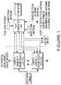
- FIG. 1illustrates a simplified block diagram of a typical installed traffic collision avoidance system or traffic alert and collision avoidance system (TCAS) system.
- TCAS-II systemswhich are approved to TSO-C119 and meet requirements in Radio Technical Commission for Aeronautics (RTCA) document DO-185 may require top and bottom antennas connected to the TCAS computer unit for generating interrogations to airborne intruders and processing replies from the intruder's transponder system (e.g., Mode S, air traffic control radar beacon system (ATCRBS), or identification, friend or foe (IFF)).
- TCAS-II systemswhich are approved to TSO-C119 and meet requirements in Radio Technical Commission for Aeronautics (RTCA) document DO-185 may require top and bottom antennas connected to the TCAS computer unit for generating interrogations to airborne intruders and processing replies from the intruder's transponder system (e.g., Mode S, air traffic control radar beacon system (ATCRBS), or identification, friend or foe (IFF)).
- the TCAS-II systemmay perform most interrogation and reply processing out of the top L-band directional antenna, per the DO-185 Minimum Operational Performance Specification (MOPS).
- MOPSDO-185 Minimum Operational Performance Specification
- the bottom L-band antennamay be required in order to provide adequate surveillance coverage when the top antenna's performance is degraded due to aircraft geometry or other obstructions.
- DO-185may require the top antenna to be directional and perform directional interrogation and reply processing; however, the bottom antenna may either be directional or omnidirectional.
- TCAS-II systemsmay operate with either a bottom L-band directional or L-band omnidirectional antenna.
- TCAS-II systemsmay be employed on a number of different aircraft types with a bottom omnidirectional antenna and provide desired performance.
- One advantage of employing a bottom omnidirectional antennais a significant installation cost and weight savings.
- the omnidirectional antenna's costis a fraction of the cost of a directional antenna.
- a directional antennarequires 4 coaxial cables between the TCAS computer unit and the antenna. An omnidirectional antenna reduces this to a single coaxial cable.
- an aircraftmay include transponders, such as Mode S diversity transponders that are separate from the TCAS system.
- Mode S transponderscan be approved to DO-181.
- the Mode S diversity transpondershave their own antennas, and may communicate across an interface to the TCAS system.
- the TCAS and transponderXPDR
- Both systemsmay require top and bottom (diversity) antennas connected to the TCAS and transponder units.
- DMEDistance measuring equipment
- DO-189may use a bottom L-band omnidirectional antenna. Since L-band omnidirectional antennas have a wide frequency response, many of the commercially available antennas will meet the requirements of multiple L-band systems (e.g., TCAS, transponder, DME) and therefore will have multiple TSO approvals for the various systems.
- L-band omnidirectional antennashave a wide frequency response, many of the commercially available antennas will meet the requirements of multiple L-band systems (e.g., TCAS, transponder, DME) and therefore will have multiple TSO approvals for the various systems.
- a systemcan include a transponder processor.
- the systemcan also include a top antenna receiver configured to connect to a top antenna.
- the transponder processorcan be configured to communicate using the top antenna.
- the systemcan also include a bottom antenna receiver configured to connect to a first bottom antenna, wherein the transponder processor is configured to communicate using the first bottom antenna.
- the systemcan further include a distance measure equipment processor integrated with the transponder processor and configured to measure distance using a second bottom antenna.
- a methodcan include receiving a first transponder signal at a transponder processor via a top antenna and top antenna receiver.
- the methodcan also include receiving a second transponder signal at the transponder processor via a first bottom antenna and a bottom antenna receiver.
- the methodcan further include performing a distance measure equipment function at a distance measure processor using a second bottom antenna.
- the distance measure processorcan be integrated with the transponder processor.
- An apparatuscan include means for receiving a first transponder signal at a transponder processor via a top antenna.
- the apparatuscan also include means for receiving a second transponder signal at the transponder processor via a first bottom antenna.
- the apparatuscan further include means for performing a distance measure equipment function at a distance measure processor using a second bottom antenna, wherein the distance measure processor is integrated with the transponder processor.
- FIG. 1illustrates a simplified block diagram of a typical installed traffic collision avoidance system or traffic alert and collision avoidance system (TCAS) system.
- TCAStraffic alert and collision avoidance system
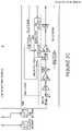
- FIG. 2(collectively comprising FIGS. 2A, 2B, 2C and 2D ) illustrates a combined TCAS-II and Mode S transponder system (TCAS/XPDR) with an integrated DME function, according to certain embodiments of the present invention.
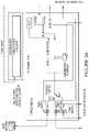
- FIG. 3(collectively comprising FIGS. 3A, 3B, 3C and 3D ) illustrates a Mode S transponder system (XPDR) with an integrated DME function, according to certain embodiments of the present invention.
- XPDRMode S transponder system
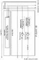
- FIG. 4illustrates a system according to certain embodiments.
- FIG. 5illustrates a method according to certain embodiments.
- a DME functioninto existing systems, such as a TCAS and/or Mode S Transponder system.
- This integrationmay remove effectively remove a DME unit as a line replaceable unit from the aircraft and may allow the TCAS and DME system to share common resources, such as radio frequency (RF), processing, and input/output (I/O) functions.
- RFradio frequency
- I/Oinput/output
- most commercial aircraftmay utilize two DME systems, which may be the approximate size, weight and cost of a Mode S Transponder.
- Certain embodiments of the present inventionmay provide for a DME system integrated into a TCAS-II and/or Mode S transponder system.
- the integrated DME/TCAS-II or DME/XPDRmay share internal resources, such as a common transmitter, while providing two independent bottom L-Band omnidirectional antennas, where one of the independent antennas may be used for either or both the TCAS-II or Mode S transponder functions and the second independent antenna may be used for the DME function.
- TCAS-II receivermay operate at 1090 MHz
- Mode S Transponder receivermay operate at 1030 MHz
- the DME receivermay be tunable from 960 to 1215 MHz with 1 MHz channel spacing.
- a common antenna that may be used for TCAS/XPDR and DME functionsmay require a receiver architecture that has a broad bandwidth, since all three functions may simultaneously receive signals. This may present a technical problem, since typical DME receiver architectures may have a tuned pre-selector filter prior to a low-noise amplifier (LNA), which may eliminate out-of-band signals.
- LNAlow-noise amplifier
- a receiver designed for a DME with this architecturewould not be useable for integrating with a TCAS-II or Mode S Transponder system. Adding a separate antenna for the DME may eliminate this constraint on the system design.
- FIGS. 2 and 3Example embodiments of the present invention are shown in FIGS. 2 and 3 .
- FIG. 2illustrates a combined TCAS-II and Mode S Transponder system (TCAS/XPDR) with an integrated DME function, according to certain embodiments of the present invention.
- FIG. 3illustrates a Mode S Transponder system (XPDR) with an integrated DME function, according to certain embodiments of the present invention. Both systems may have a separate bottom L-Band omnidirectional antenna dedicated for the DME function.
- TCAS/Mode S Transponder system (TCAS/XPDR) block diagram of FIG. 2can help to illustrate certain embodiments of the present invention.
- the Mode S Transponder system block diagram of FIG. 3may work in a similar manner to the combined TCAS/Mode S Transponder of FIG. 2 .
- the TCAS/XPDR systemmay provide the following circuitry by which the TCAS-II and Mode S Transponder functions may be implemented: power supply, processor, transmitter, receiver and I/O connector.
- the RF transmittermay be connected to a top directional antenna, and two bottom omnidirectional antennas may be coupled through RF I/O circuit blocks.
- One bottom (BOT) antennamay be dedicated for the TCAS-II and Mode S transponder function, while the other bottom antenna may be dedicated for the DME function.
- TCAS-II and Mode S Transponder transmissions on the bottom TCAS/XPDR omnidirectional antennamay be performed through a power amplifier (TX PA 0 degree (DEG)) connected to the antenna through the TOP/BOT 0 DEG/DME I/O switch block.
- TX PA 0 degree (DEG)power amplifier
- the bottom TCAS/XPDR omnidirectional antennamay be connected through the TOP/BOT 0 DEG/DME I/O switch block diagram to the TCAS/XPDR Bottom 0 degree receiver block on the RF Receiver for receiving signals for the TCAS-II and Mode S Transponder function.
- the DME functionmay be added to the system as additional circuitry which may perform the DME processing, system I/O, receiver and transmitter modulation functions.
- the DME functionmay share the L-band transmitter with the TCAS-II/Mode S Transponder function.
- the TX PA 0 degree power amplifiermay have an RF switch at the input that may allow either the TCAS-II/Mode S Transponder modulator to be connected to the amplifier (TX MOD 0) or the DME modulator to be connected to the amplifier (DME TX MOD).
- the output of the TX PA 0 blockmay be connected to either the bottom TCAS/XPDR omnidirectional antenna or the bottom DME omnidirectional antenna through the TOP/BOT 0 DEG/DME I/O block.
- the TCAS and Mode S receiver low noise amplifier (LNA) for the RF receivermay be connected to the bottom TCAS/XPDR omnidirectional antenna through the TOP/BOT 0 DEG/DME I/O block.
- the DME receiver low noise amplifier (LNA)may be connected to the bottom DME omnidirectional antenna through the TOP/BOT 0 DEG/DME I/O.
- inventions of the present inventionmay include but are not limited to a single unit which may contain separate transmitters for the TCAS-II/Mode S Transponder and DME functions, each of which may be connected to their own bottom omnidirectional L-Band antennas.
- TCAS-II/DMEmay employ a bottom directional antenna system for the TCAS-II processing and a bottom omnidirectional antenna system for the DME processing function.
- inventions of the present inventionmay provide for an integrated TCAS-II/Mode S transponder and DME system that may employ a bottom directional or omnidirectional antenna system for the TCAS-II and Mode S transponder processing and a bottom omnidirectional antenna system for the DME processing function.
- DME and TCAS-II and/or Mode S transponder functionsmay be integrated on the same circuit cards and assemblies, and share common receiver, transmitter modulation, processing, power supply, and system I/O functions.
- TCAS-II and/or Mode S transponder and DME systemmay implement other functions that also share or have separate resources for implementing the functions.
- FIG. 4illustrates a system according to certain embodiments.
- the system of FIG. 4may broadly encompass, for example, the systems illustrated in FIGS. 2 and 3 .
- a systemcan include a transponder processor 410 .
- the systemcan also include a top antenna receiver 420 configured to connect to a top antenna 425 .
- the transponder processor 410can be configured to communicate using the top antenna 425 .
- the systemcan also include a bottom antenna receiver 430 configured to connect to a first bottom antenna 435 .
- the transponder processor 410can be configured to communicate using the first bottom antenna 435 .
- the systemcan further include a distance measure equipment processor 440 integrated with the transponder processor 410 and configured to measure distance using a second bottom antenna 437 .
- the second bottom antenna 437may be used exclusively for distance measure functions, and not for transponder functions.
- the systemcan also optionally include an avionics processor 450 configured to communicate using the top antenna 425 and the first bottom antenna 435 .
- the avionics processor 450can be integrated with the transponder processor 410 and the distance measure equipment processor 440 .
- the avionics processor 450can be a processor of a traffic collision avoidance system or a traffic alert and collision avoidance system. Alternatively, the avionics processor 450 can be a processor of a traffic awareness system or ADS-B IN system.
- the transponder processor 410 , top antenna receiver 420 , bottom antenna receiver 430 , and distance measure equipment processor 440can be provided as a single line replaceable unit.
- the avionics processor 450can also be included in the same line replaceable unit.
- the distance measure equipment processor 440can be provided on a different circuit card assembly from the transponder processor 410 .
- the distance measure equipment processor 440can be provided on a same circuit card assembly as a distance measure equipment receiver 460 .
- the distance measure equipment processor 440 and the transponder processor 410can be implemented on a same chip or a same circuit card assembly.
- the avionics processor 450can also be implemented on the same chip or the same circuit card assembly with the distance measure equipment processor 440 and the transponder processor 410 .
- a single transmitter or a single receiver, or bothmay be shared among the transponder, the avionics, and the DME functions.
- a single transmitter or a single receiver, or bothmay be shared among the transponder, the avionics, and the DME functions.
- transpondercan serve as a single LRU in certain embodiments of the present invention.
- a single LRU I/O connectorcan be used to interface to a power supply, transponder processor and/or avionics processor, RF receiver, RF transceiver, and DME transceiver and processor.
- FIG. 5illustrates a method according to certain embodiments of the present invention.
- the method of FIG. 5may be implemented by the systems illustrated in FIGS. 2, 3, and 4 .
- the methodcan include, at 510 , receiving a first transponder signal at a transponder processor via a top antenna and top antenna receiver.
- the methodcan also include, at 520 , receiving a second transponder signal at the transponder processor via a first bottom antenna and a bottom antenna receiver.
- the methodcan further include, at 530 , performing a distance measure equipment function at a distance measure processor using a second bottom antenna.
- the distance measure processorcan be integrated with the transponder processor.
- the methodcan also include, at 540 , receiving a first avionics signal at an avionics processor via the top antenna.
- the methodcan further include, at 550 , receiving a second avionics signal at the avionics processor via the first bottom antenna.
- the avionics processorcan be integrated with the transponder processor and the distance measure equipment processor.
- the avionics processorcan be a traffic collision avoidance system or traffic alert and collision avoidance system.
- the avionics processorcan be a traffic awareness system or ADS-B IN system.
- the transponder processor, top antenna receiver, and bottom antenna receivercan be provided as a single line replaceable unit together with a distance measure equipment receiver and the distance measure equipment processor.
- the avionics processorcan also be included in the same single line replaceable unit.
- the distance measure equipment processorcan be provided on a different circuit card assembly from the transponder processor.
- the distance measure equipment processorcan also be provided on a different circuit card assembly from the avionics processor.
- the avionics processorcan be on a different circuit card assembly from the transponder processor.
- the distance measure equipment processorcan be provided on a same circuit card assembly as a distance measure equipment receiver.
- the distance measure equipment processor and the transponder processorcan be implemented on a same chip or a same circuit card assembly.
- the distance measure equipment processor and the avionics processorcan also be implemented on a same chip or a same circuit card assembly.
Landscapes
- Engineering & Computer Science (AREA)
- Remote Sensing (AREA)
- Radar, Positioning & Navigation (AREA)
- Physics & Mathematics (AREA)
- General Physics & Mathematics (AREA)
- Aviation & Aerospace Engineering (AREA)
- Computer Networks & Wireless Communication (AREA)
- Electromagnetism (AREA)
- Astronomy & Astrophysics (AREA)
- Radar Systems Or Details Thereof (AREA)
Abstract
Description
Claims (12)
Priority Applications (1)
| Application Number | Priority Date | Filing Date | Title |
|---|---|---|---|
| US15/412,438US11480667B2 (en) | 2016-01-22 | 2017-01-23 | Systems and methods for providing an integrated TCAS, transponder, and DME system using a dedicated DME antenna |
Applications Claiming Priority (2)
| Application Number | Priority Date | Filing Date | Title |
|---|---|---|---|
| US201662286296P | 2016-01-22 | 2016-01-22 | |
| US15/412,438US11480667B2 (en) | 2016-01-22 | 2017-01-23 | Systems and methods for providing an integrated TCAS, transponder, and DME system using a dedicated DME antenna |
Publications (2)
| Publication Number | Publication Date |
|---|---|
| US20170358227A1 US20170358227A1 (en) | 2017-12-14 |
| US11480667B2true US11480667B2 (en) | 2022-10-25 |
Family
ID=60573017
Family Applications (1)
| Application Number | Title | Priority Date | Filing Date |
|---|---|---|---|
| US15/412,438Active2038-01-20US11480667B2 (en) | 2016-01-22 | 2017-01-23 | Systems and methods for providing an integrated TCAS, transponder, and DME system using a dedicated DME antenna |
Country Status (1)
| Country | Link |
|---|---|
| US (1) | US11480667B2 (en) |
Families Citing this family (8)
| Publication number | Priority date | Publication date | Assignee | Title |
|---|---|---|---|---|
| EP3698166A1 (en)* | 2017-10-16 | 2020-08-26 | Aviation Communication & Surveillance Systems, LLC | Systems and methods for providing l-band rf architectures |
| CN109087536B (en)* | 2018-09-13 | 2020-06-30 | 四川九洲空管科技有限责任公司 | Airborne Collision Avoidance System Antenna Self-Check and Degradation Method |
| US11038728B1 (en) | 2020-10-01 | 2021-06-15 | Honeywell International Inc. | Demodulating surveillance signals |
| US11258469B1 (en) | 2020-10-01 | 2022-02-22 | Honeywell International Inc. | Demodulating surveillance signals |
| US11356309B2 (en) | 2020-10-01 | 2022-06-07 | Honeywell International Inc. | Demodulating surveillance signals |
| US11356134B1 (en)* | 2021-01-14 | 2022-06-07 | Rockwell Collins, Inc. | Integrated TCAS/transponder transmitter architecture |
| US11901922B2 (en) | 2021-09-20 | 2024-02-13 | Honeywell International Inc. | Radio-frequency transmitter |
| US20230308120A1 (en)* | 2022-03-28 | 2023-09-28 | Sagetech Avionics, Inc. | Combined Interrogator and Transponder with an Omnidirectional Antenna |
Citations (16)
| Publication number | Priority date | Publication date | Assignee | Title |
|---|---|---|---|---|
| US5212813A (en)* | 1990-02-28 | 1993-05-18 | Dassault Aviation | Device for the coupling to a common antenna of at least two transmitting and/or receiving devices |
| US20050156777A1 (en)* | 2004-01-15 | 2005-07-21 | Honeywell International, Inc. | Integrated traffic surveillance apparatus |
| US20080068250A1 (en)* | 2006-09-18 | 2008-03-20 | Honeywell International Inc. | Distributed and cable reduced tcas |
| US20080238759A1 (en)* | 2007-03-30 | 2008-10-02 | Honeywell International Inc. | Integrated distance measuring equipment and transponder system and method |
| US7535405B2 (en)* | 2006-02-28 | 2009-05-19 | Honeywell International Inc. | Method and apparatus for a multifunction radio |
| US20100171647A1 (en)* | 2009-01-07 | 2010-07-08 | Honeywell International Inc. | Enhanced aircraft transponder reliability |
| US20100253565A1 (en)* | 2006-04-10 | 2010-10-07 | Piesinger Gregory H | Method and apparatus to increase ADS-B squitter reception sensitivity |
| US8019529B1 (en)* | 2007-08-17 | 2011-09-13 | Rockwell Collins, Inc. | Runway and airport incursion alerting system and method |
| US8344935B1 (en)* | 2010-07-22 | 2013-01-01 | Rockwell Collins, Inc. | Multi-waveform antenna and remote electronics for avionics |
| US8593330B2 (en)* | 2011-07-11 | 2013-11-26 | Honeywell International Inc. | Multichannel, multimode, multifunction L-band radio transceiver |
| US20160013923A1 (en)* | 2014-07-11 | 2016-01-14 | Honeywell International Inc. | Flexible integrated communications and navigation transceiver system |
| US9405005B1 (en)* | 2012-04-24 | 2016-08-02 | The United States Of America As Represented By The Administrator Of The National Aeronautics And Space Administration | Automatic dependent surveillance broadcast (ADS-B) system for ownership and traffic situational awareness |
| US9478140B2 (en)* | 2014-08-29 | 2016-10-25 | Honeywell International Inc. | System and method for displaying traffic and associated alerts on a three-dimensional airport moving map display |
| US9513376B1 (en)* | 2012-09-25 | 2016-12-06 | Rockwell Collins, Inc. | Low-cost high integrity integrated multi-sensor precision navigation system |
| US9857461B2 (en)* | 2013-10-14 | 2018-01-02 | Aviation Communication & Surveillance Systems Llc | Systems and methods for remote L-band smart antenna distance measuring equipment diversity |
| US10001376B1 (en)* | 2015-02-19 | 2018-06-19 | Rockwell Collins, Inc. | Aircraft position monitoring system and method |
- 2017
- 2017-01-23USUS15/412,438patent/US11480667B2/enactiveActive
Patent Citations (19)
| Publication number | Priority date | Publication date | Assignee | Title |
|---|---|---|---|---|
| US5212813A (en)* | 1990-02-28 | 1993-05-18 | Dassault Aviation | Device for the coupling to a common antenna of at least two transmitting and/or receiving devices |
| US20050156777A1 (en)* | 2004-01-15 | 2005-07-21 | Honeywell International, Inc. | Integrated traffic surveillance apparatus |
| US7006032B2 (en)* | 2004-01-15 | 2006-02-28 | Honeywell International, Inc. | Integrated traffic surveillance apparatus |
| US7535405B2 (en)* | 2006-02-28 | 2009-05-19 | Honeywell International Inc. | Method and apparatus for a multifunction radio |
| US20100253565A1 (en)* | 2006-04-10 | 2010-10-07 | Piesinger Gregory H | Method and apparatus to increase ADS-B squitter reception sensitivity |
| US20080068250A1 (en)* | 2006-09-18 | 2008-03-20 | Honeywell International Inc. | Distributed and cable reduced tcas |
| US7583223B2 (en)* | 2006-09-18 | 2009-09-01 | Honeywell International Inc. | Distributed and Cable reduced TCAS |
| US20080238759A1 (en)* | 2007-03-30 | 2008-10-02 | Honeywell International Inc. | Integrated distance measuring equipment and transponder system and method |
| US7525474B2 (en)* | 2007-03-30 | 2009-04-28 | Honeywell International Inc. | Integrated distance measuring equipment and transponder system and method |
| US8019529B1 (en)* | 2007-08-17 | 2011-09-13 | Rockwell Collins, Inc. | Runway and airport incursion alerting system and method |
| US20100171647A1 (en)* | 2009-01-07 | 2010-07-08 | Honeywell International Inc. | Enhanced aircraft transponder reliability |
| US8344935B1 (en)* | 2010-07-22 | 2013-01-01 | Rockwell Collins, Inc. | Multi-waveform antenna and remote electronics for avionics |
| US8593330B2 (en)* | 2011-07-11 | 2013-11-26 | Honeywell International Inc. | Multichannel, multimode, multifunction L-band radio transceiver |
| US9405005B1 (en)* | 2012-04-24 | 2016-08-02 | The United States Of America As Represented By The Administrator Of The National Aeronautics And Space Administration | Automatic dependent surveillance broadcast (ADS-B) system for ownership and traffic situational awareness |
| US9513376B1 (en)* | 2012-09-25 | 2016-12-06 | Rockwell Collins, Inc. | Low-cost high integrity integrated multi-sensor precision navigation system |
| US9857461B2 (en)* | 2013-10-14 | 2018-01-02 | Aviation Communication & Surveillance Systems Llc | Systems and methods for remote L-band smart antenna distance measuring equipment diversity |
| US20160013923A1 (en)* | 2014-07-11 | 2016-01-14 | Honeywell International Inc. | Flexible integrated communications and navigation transceiver system |
| US9478140B2 (en)* | 2014-08-29 | 2016-10-25 | Honeywell International Inc. | System and method for displaying traffic and associated alerts on a three-dimensional airport moving map display |
| US10001376B1 (en)* | 2015-02-19 | 2018-06-19 | Rockwell Collins, Inc. | Aircraft position monitoring system and method |
Also Published As
| Publication number | Publication date |
|---|---|
| US20170358227A1 (en) | 2017-12-14 |
Similar Documents
| Publication | Publication Date | Title |
|---|---|---|
| US11480667B2 (en) | Systems and methods for providing an integrated TCAS, transponder, and DME system using a dedicated DME antenna | |
| US7978121B2 (en) | Distributed and cable reduced TCAS | |
| US8768540B2 (en) | Integrated avionics system | |
| US9857461B2 (en) | Systems and methods for remote L-band smart antenna distance measuring equipment diversity | |
| US7525474B2 (en) | Integrated distance measuring equipment and transponder system and method | |
| US5596326A (en) | Secondary surveillance radar interrogation system using dual frequencies | |
| US6545632B1 (en) | Radar systems and methods | |
| CN104579413B (en) | A kind of comprehensive radio frequency system | |
| US6792058B1 (en) | Digital receiving system for dense environment of aircraft | |
| US5923293A (en) | Method and apparatus for accomplishing extended range TCAS using a dual bandwidth receiver | |
| WO2012003188A1 (en) | Transponder decoder | |
| US11041950B2 (en) | Surveillance systems providing integrated functional redundancy | |
| US8179302B2 (en) | Apparatus for sharing an omnidirectional antenna between an IFF transponder and an IFF interrogator | |
| US7383124B1 (en) | ADS-B broadcast monitoring system and method | |
| US7835827B2 (en) | Methods, systems and computer program products for communicating auditory alert to aircraft | |
| EP3273262A1 (en) | Monopulse secondary surveillance radar | |
| US20180033319A1 (en) | Systems and methods for providing an integrated tcas and dme system using an omnidirectional antenna | |
| US10714815B2 (en) | Systems and methods for providing a DME L-band shared antenna | |
| US9116236B1 (en) | Aircraft distance measuring equipment with directional interrogation | |
| US9869745B1 (en) | Systems and methods for improving bearing reception on a TCAS or other surveillance system | |
| EP2762915B1 (en) | Method for operating a passive radar | |
| US11194041B2 (en) | Systems and methods for providing L-band RF architectures | |
| GB2449123A (en) | Pilot Warning System and Method |
Legal Events
| Date | Code | Title | Description |
|---|---|---|---|
| AS | Assignment | Owner name:AVIATION COMMUNICATION & SURVEILLANCE SYSTEMS LLC, ARIZONA Free format text:ASSIGNMENT OF ASSIGNORS INTEREST;ASSIGNOR:TROXEL, JAMES R.;REEL/FRAME:043537/0863 Effective date:20170907 Owner name:AVIATION COMMUNICATION & SURVEILLANCE SYSTEMS LLC, Free format text:ASSIGNMENT OF ASSIGNORS INTEREST;ASSIGNOR:TROXEL, JAMES R.;REEL/FRAME:043537/0863 Effective date:20170907 | |
| STPP | Information on status: patent application and granting procedure in general | Free format text:NON FINAL ACTION MAILED | |
| STPP | Information on status: patent application and granting procedure in general | Free format text:RESPONSE TO NON-FINAL OFFICE ACTION ENTERED AND FORWARDED TO EXAMINER | |
| STPP | Information on status: patent application and granting procedure in general | Free format text:FINAL REJECTION MAILED | |
| STPP | Information on status: patent application and granting procedure in general | Free format text:DOCKETED NEW CASE - READY FOR EXAMINATION | |
| STPP | Information on status: patent application and granting procedure in general | Free format text:NON FINAL ACTION MAILED | |
| STPP | Information on status: patent application and granting procedure in general | Free format text:RESPONSE TO NON-FINAL OFFICE ACTION ENTERED AND FORWARDED TO EXAMINER | |
| STPP | Information on status: patent application and granting procedure in general | Free format text:DOCKETED NEW CASE - READY FOR EXAMINATION | |
| STPP | Information on status: patent application and granting procedure in general | Free format text:NON FINAL ACTION MAILED | |
| STPP | Information on status: patent application and granting procedure in general | Free format text:RESPONSE TO NON-FINAL OFFICE ACTION ENTERED AND FORWARDED TO EXAMINER | |
| STPP | Information on status: patent application and granting procedure in general | Free format text:FINAL REJECTION MAILED | |
| STPP | Information on status: patent application and granting procedure in general | Free format text:RESPONSE AFTER FINAL ACTION FORWARDED TO EXAMINER | |
| STPP | Information on status: patent application and granting procedure in general | Free format text:ADVISORY ACTION MAILED | |
| STPP | Information on status: patent application and granting procedure in general | Free format text:NON FINAL ACTION MAILED | |
| STPP | Information on status: patent application and granting procedure in general | Free format text:RESPONSE TO NON-FINAL OFFICE ACTION ENTERED AND FORWARDED TO EXAMINER | |
| STPP | Information on status: patent application and granting procedure in general | Free format text:NOTICE OF ALLOWANCE MAILED -- APPLICATION RECEIVED IN OFFICE OF PUBLICATIONS | |
| STPP | Information on status: patent application and granting procedure in general | Free format text:PUBLICATIONS -- ISSUE FEE PAYMENT VERIFIED | |
| STCF | Information on status: patent grant | Free format text:PATENTED CASE |