US11478789B2 - Automated microscopic cell analysis - Google Patents
Automated microscopic cell analysisDownload PDFInfo
- Publication number
- US11478789B2 US11478789B2US15/017,498US201615017498AUS11478789B2US 11478789 B2US11478789 B2US 11478789B2US 201615017498 AUS201615017498 AUS 201615017498AUS 11478789 B2US11478789 B2US 11478789B2
- Authority
- US
- United States
- Prior art keywords
- sample
- imaging chamber
- volume
- diluent
- chamber
- Prior art date
- Legal status (The legal status is an assumption and is not a legal conclusion. Google has not performed a legal analysis and makes no representation as to the accuracy of the status listed.)
- Active, expires
Links
Images


Classifications
- G—PHYSICS
- G01—MEASURING; TESTING
- G01N—INVESTIGATING OR ANALYSING MATERIALS BY DETERMINING THEIR CHEMICAL OR PHYSICAL PROPERTIES
- G01N15/00—Investigating characteristics of particles; Investigating permeability, pore-volume or surface-area of porous materials
- G01N15/10—Investigating individual particles
- G01N15/14—Optical investigation techniques, e.g. flow cytometry
- G01N15/1434—Optical arrangements
- B—PERFORMING OPERATIONS; TRANSPORTING
- B01—PHYSICAL OR CHEMICAL PROCESSES OR APPARATUS IN GENERAL
- B01L—CHEMICAL OR PHYSICAL LABORATORY APPARATUS FOR GENERAL USE
- B01L3/00—Containers or dishes for laboratory use, e.g. laboratory glassware; Droppers
- B01L3/50—Containers for the purpose of retaining a material to be analysed, e.g. test tubes
- B01L3/502—Containers for the purpose of retaining a material to be analysed, e.g. test tubes with fluid transport, e.g. in multi-compartment structures
- B01L3/5027—Containers for the purpose of retaining a material to be analysed, e.g. test tubes with fluid transport, e.g. in multi-compartment structures by integrated microfluidic structures, i.e. dimensions of channels and chambers are such that surface tension forces are important, e.g. lab-on-a-chip
- B01L3/502715—Containers for the purpose of retaining a material to be analysed, e.g. test tubes with fluid transport, e.g. in multi-compartment structures by integrated microfluidic structures, i.e. dimensions of channels and chambers are such that surface tension forces are important, e.g. lab-on-a-chip characterised by interfacing components, e.g. fluidic, electrical, optical or mechanical interfaces
- B—PERFORMING OPERATIONS; TRANSPORTING
- B01—PHYSICAL OR CHEMICAL PROCESSES OR APPARATUS IN GENERAL
- B01L—CHEMICAL OR PHYSICAL LABORATORY APPARATUS FOR GENERAL USE
- B01L3/00—Containers or dishes for laboratory use, e.g. laboratory glassware; Droppers
- B01L3/50—Containers for the purpose of retaining a material to be analysed, e.g. test tubes
- B01L3/502—Containers for the purpose of retaining a material to be analysed, e.g. test tubes with fluid transport, e.g. in multi-compartment structures
- B01L3/5027—Containers for the purpose of retaining a material to be analysed, e.g. test tubes with fluid transport, e.g. in multi-compartment structures by integrated microfluidic structures, i.e. dimensions of channels and chambers are such that surface tension forces are important, e.g. lab-on-a-chip
- B01L3/502738—Containers for the purpose of retaining a material to be analysed, e.g. test tubes with fluid transport, e.g. in multi-compartment structures by integrated microfluidic structures, i.e. dimensions of channels and chambers are such that surface tension forces are important, e.g. lab-on-a-chip characterised by integrated valves
- G—PHYSICS
- G01—MEASURING; TESTING
- G01N—INVESTIGATING OR ANALYSING MATERIALS BY DETERMINING THEIR CHEMICAL OR PHYSICAL PROPERTIES
- G01N15/00—Investigating characteristics of particles; Investigating permeability, pore-volume or surface-area of porous materials
- G01N15/10—Investigating individual particles
- G01N15/14—Optical investigation techniques, e.g. flow cytometry
- G01N15/1429—Signal processing
- G01N15/1433—Signal processing using image recognition
- G01N15/1463—
- G—PHYSICS
- G01—MEASURING; TESTING
- G01N—INVESTIGATING OR ANALYSING MATERIALS BY DETERMINING THEIR CHEMICAL OR PHYSICAL PROPERTIES
- G01N15/00—Investigating characteristics of particles; Investigating permeability, pore-volume or surface-area of porous materials
- G01N15/10—Investigating individual particles
- G01N15/14—Optical investigation techniques, e.g. flow cytometry
- G01N15/1484—Optical investigation techniques, e.g. flow cytometry microstructural devices
- G—PHYSICS
- G01—MEASURING; TESTING
- G01N—INVESTIGATING OR ANALYSING MATERIALS BY DETERMINING THEIR CHEMICAL OR PHYSICAL PROPERTIES
- G01N33/00—Investigating or analysing materials by specific methods not covered by groups G01N1/00 - G01N31/00
- G01N33/48—Biological material, e.g. blood, urine; Haemocytometers
- G01N33/483—Physical analysis of biological material
- G01N33/487—Physical analysis of biological material of liquid biological material
- G01N33/49—Blood
- G01N33/4915—Blood using flow cells
- G—PHYSICS
- G01—MEASURING; TESTING
- G01N—INVESTIGATING OR ANALYSING MATERIALS BY DETERMINING THEIR CHEMICAL OR PHYSICAL PROPERTIES
- G01N33/00—Investigating or analysing materials by specific methods not covered by groups G01N1/00 - G01N31/00
- G01N33/48—Biological material, e.g. blood, urine; Haemocytometers
- G01N33/50—Chemical analysis of biological material, e.g. blood, urine; Testing involving biospecific ligand binding methods; Immunological testing
- G01N33/5005—Chemical analysis of biological material, e.g. blood, urine; Testing involving biospecific ligand binding methods; Immunological testing involving human or animal cells
- G01N33/5094—Chemical analysis of biological material, e.g. blood, urine; Testing involving biospecific ligand binding methods; Immunological testing involving human or animal cells for blood cell populations
- G—PHYSICS
- G01—MEASURING; TESTING
- G01N—INVESTIGATING OR ANALYSING MATERIALS BY DETERMINING THEIR CHEMICAL OR PHYSICAL PROPERTIES
- G01N33/00—Investigating or analysing materials by specific methods not covered by groups G01N1/00 - G01N31/00
- G01N33/48—Biological material, e.g. blood, urine; Haemocytometers
- G01N33/50—Chemical analysis of biological material, e.g. blood, urine; Testing involving biospecific ligand binding methods; Immunological testing
- G01N33/80—Chemical analysis of biological material, e.g. blood, urine; Testing involving biospecific ligand binding methods; Immunological testing involving blood groups or blood types or red blood cells
- G—PHYSICS
- G06—COMPUTING OR CALCULATING; COUNTING
- G06V—IMAGE OR VIDEO RECOGNITION OR UNDERSTANDING
- G06V20/00—Scenes; Scene-specific elements
- G06V20/60—Type of objects
- G06V20/69—Microscopic objects, e.g. biological cells or cellular parts
- G06V20/693—Acquisition
- G—PHYSICS
- G06—COMPUTING OR CALCULATING; COUNTING
- G06V—IMAGE OR VIDEO RECOGNITION OR UNDERSTANDING
- G06V20/00—Scenes; Scene-specific elements
- G06V20/60—Type of objects
- G06V20/69—Microscopic objects, e.g. biological cells or cellular parts
- G06V20/698—Matching; Classification
- B—PERFORMING OPERATIONS; TRANSPORTING
- B01—PHYSICAL OR CHEMICAL PROCESSES OR APPARATUS IN GENERAL
- B01L—CHEMICAL OR PHYSICAL LABORATORY APPARATUS FOR GENERAL USE
- B01L2200/00—Solutions for specific problems relating to chemical or physical laboratory apparatus
- B01L2200/02—Adapting objects or devices to another
- B01L2200/026—Fluid interfacing between devices or objects, e.g. connectors, inlet details
- B01L2200/027—Fluid interfacing between devices or objects, e.g. connectors, inlet details for microfluidic devices
- B—PERFORMING OPERATIONS; TRANSPORTING
- B01—PHYSICAL OR CHEMICAL PROCESSES OR APPARATUS IN GENERAL
- B01L—CHEMICAL OR PHYSICAL LABORATORY APPARATUS FOR GENERAL USE
- B01L2200/00—Solutions for specific problems relating to chemical or physical laboratory apparatus
- B01L2200/06—Fluid handling related problems
- B01L2200/0605—Metering of fluids
- B—PERFORMING OPERATIONS; TRANSPORTING
- B01—PHYSICAL OR CHEMICAL PROCESSES OR APPARATUS IN GENERAL
- B01L—CHEMICAL OR PHYSICAL LABORATORY APPARATUS FOR GENERAL USE
- B01L2200/00—Solutions for specific problems relating to chemical or physical laboratory apparatus
- B01L2200/06—Fluid handling related problems
- B01L2200/0647—Handling flowable solids, e.g. microscopic beads, cells, particles
- B—PERFORMING OPERATIONS; TRANSPORTING
- B01—PHYSICAL OR CHEMICAL PROCESSES OR APPARATUS IN GENERAL
- B01L—CHEMICAL OR PHYSICAL LABORATORY APPARATUS FOR GENERAL USE
- B01L2200/00—Solutions for specific problems relating to chemical or physical laboratory apparatus
- B01L2200/16—Reagents, handling or storing thereof
- B—PERFORMING OPERATIONS; TRANSPORTING
- B01—PHYSICAL OR CHEMICAL PROCESSES OR APPARATUS IN GENERAL
- B01L—CHEMICAL OR PHYSICAL LABORATORY APPARATUS FOR GENERAL USE
- B01L2300/00—Additional constructional details
- B01L2300/06—Auxiliary integrated devices, integrated components
- B01L2300/0627—Sensor or part of a sensor is integrated
- B—PERFORMING OPERATIONS; TRANSPORTING
- B01—PHYSICAL OR CHEMICAL PROCESSES OR APPARATUS IN GENERAL
- B01L—CHEMICAL OR PHYSICAL LABORATORY APPARATUS FOR GENERAL USE
- B01L2400/00—Moving or stopping fluids
- B01L2400/06—Valves, specific forms thereof
- B01L2400/0633—Valves, specific forms thereof with moving parts
- B01L2400/0644—Valves, specific forms thereof with moving parts rotary valves
- G—PHYSICS
- G01—MEASURING; TESTING
- G01N—INVESTIGATING OR ANALYSING MATERIALS BY DETERMINING THEIR CHEMICAL OR PHYSICAL PROPERTIES
- G01N1/00—Sampling; Preparing specimens for investigation
- G01N1/02—Devices for withdrawing samples
- G01N1/10—Devices for withdrawing samples in the liquid or fluent state
- G—PHYSICS
- G01—MEASURING; TESTING
- G01N—INVESTIGATING OR ANALYSING MATERIALS BY DETERMINING THEIR CHEMICAL OR PHYSICAL PROPERTIES
- G01N1/00—Sampling; Preparing specimens for investigation
- G01N1/28—Preparing specimens for investigation including physical details of (bio-)chemical methods covered elsewhere, e.g. G01N33/50, C12Q
- G01N1/30—Staining; Impregnating ; Fixation; Dehydration; Multistep processes for preparing samples of tissue, cell or nucleic acid material and the like for analysis
- G—PHYSICS
- G01—MEASURING; TESTING
- G01N—INVESTIGATING OR ANALYSING MATERIALS BY DETERMINING THEIR CHEMICAL OR PHYSICAL PROPERTIES
- G01N15/00—Investigating characteristics of particles; Investigating permeability, pore-volume or surface-area of porous materials
- G01N15/01—Investigating characteristics of particles; Investigating permeability, pore-volume or surface-area of porous materials specially adapted for biological cells, e.g. blood cells
- G01N2015/0065—
- G01N2015/008—
- G01N2015/0084—
- G—PHYSICS
- G01—MEASURING; TESTING
- G01N—INVESTIGATING OR ANALYSING MATERIALS BY DETERMINING THEIR CHEMICAL OR PHYSICAL PROPERTIES
- G01N15/00—Investigating characteristics of particles; Investigating permeability, pore-volume or surface-area of porous materials
- G01N15/01—Investigating characteristics of particles; Investigating permeability, pore-volume or surface-area of porous materials specially adapted for biological cells, e.g. blood cells
- G01N2015/016—White blood cells
- G—PHYSICS
- G01—MEASURING; TESTING
- G01N—INVESTIGATING OR ANALYSING MATERIALS BY DETERMINING THEIR CHEMICAL OR PHYSICAL PROPERTIES
- G01N15/00—Investigating characteristics of particles; Investigating permeability, pore-volume or surface-area of porous materials
- G01N15/01—Investigating characteristics of particles; Investigating permeability, pore-volume or surface-area of porous materials specially adapted for biological cells, e.g. blood cells
- G01N2015/018—Platelets
- G—PHYSICS
- G01—MEASURING; TESTING
- G01N—INVESTIGATING OR ANALYSING MATERIALS BY DETERMINING THEIR CHEMICAL OR PHYSICAL PROPERTIES
- G01N15/00—Investigating characteristics of particles; Investigating permeability, pore-volume or surface-area of porous materials
- G01N15/10—Investigating individual particles
- G01N2015/1006—Investigating individual particles for cytology
- G—PHYSICS
- G01—MEASURING; TESTING
- G01N—INVESTIGATING OR ANALYSING MATERIALS BY DETERMINING THEIR CHEMICAL OR PHYSICAL PROPERTIES
- G01N15/00—Investigating characteristics of particles; Investigating permeability, pore-volume or surface-area of porous materials
- G01N15/10—Investigating individual particles
- G01N15/14—Optical investigation techniques, e.g. flow cytometry
- G01N2015/1486—Counting the particles
- G—PHYSICS
- G01—MEASURING; TESTING
- G01N—INVESTIGATING OR ANALYSING MATERIALS BY DETERMINING THEIR CHEMICAL OR PHYSICAL PROPERTIES
- G01N35/00—Automatic analysis not limited to methods or materials provided for in any single one of groups G01N1/00 - G01N33/00; Handling materials therefor
- G01N35/00029—Automatic analysis not limited to methods or materials provided for in any single one of groups G01N1/00 - G01N33/00; Handling materials therefor provided with flat sample substrates, e.g. slides
- G01N2035/00099—Characterised by type of test elements
- G01N2035/00148—Test cards, e.g. Biomerieux or McDonnel multiwell test cards
- G—PHYSICS
- G01—MEASURING; TESTING
- G01N—INVESTIGATING OR ANALYSING MATERIALS BY DETERMINING THEIR CHEMICAL OR PHYSICAL PROPERTIES
- G01N21/00—Investigating or analysing materials by the use of optical means, i.e. using sub-millimetre waves, infrared, visible or ultraviolet light
- G01N21/01—Arrangements or apparatus for facilitating the optical investigation
- G01N21/03—Cuvette constructions
- G01N21/05—Flow-through cuvettes
- Y—GENERAL TAGGING OF NEW TECHNOLOGICAL DEVELOPMENTS; GENERAL TAGGING OF CROSS-SECTIONAL TECHNOLOGIES SPANNING OVER SEVERAL SECTIONS OF THE IPC; TECHNICAL SUBJECTS COVERED BY FORMER USPC CROSS-REFERENCE ART COLLECTIONS [XRACs] AND DIGESTS
- Y10—TECHNICAL SUBJECTS COVERED BY FORMER USPC
- Y10T—TECHNICAL SUBJECTS COVERED BY FORMER US CLASSIFICATION
- Y10T436/00—Chemistry: analytical and immunological testing
- Y10T436/10—Composition for standardization, calibration, simulation, stabilization, preparation or preservation; processes of use in preparation for chemical testing
- Y10T436/101666—Particle count or volume standard or control [e.g., platelet count standards, etc.]
Definitions
- a diagnostic test referred to as a “CBC with differential”, also known as a “CBC with five part diff”,will also include Neutrophil granulocytes (NEU), Lymphocytes (LYM), Monocytes (MON), Eosinophil granulocytes (EO) and Basophil granulocytes (BASO) per unit volume or as a percentage of the white blood cells (WBC).
- the CBC with differentialalso may include counts of Immature Cells (IC), nucleated Red Blood Cells (nRBC), and Reticulocytes (RETIC) per unit volume of the blood sample.
- CCUCritical Care Unit
- ICUIntensive Care Unit
- Another object of the inventionis to create a substantially homogenous monolayer of cells of a diluted sample in a single use disposable device and to perform a CBC analysis in a few minutes. Another objective is to provide a sample collection device that can easily be operated by a user to obtain a biological sample for analysis. Yet another objective is to provide all of the fluidic components of an apparatus to perform a CBC in a single-use device, so as to prevent cross contamination between samples and to avoid the need for cleaning and washing of fluidic components. Another objective of the present invention is to provide internal monitoring of the critical process steps of counting cells, so that a potentially erroneous result can be flagged.
- Still another objectiveis to provide a method of performing the CBC immediately after collecting the sample, and to eliminate transport of the sample to a laboratory or storage of the sample.
- the disclosureprovides improved methods, systems, and devices for performing counts and measurements of particles in a biological sample. Aspects of the disclosure are directed to determining the concentration of one or more types of particles and providing the result as the number of such particles per unit volume of the biological sample in a few minutes.
- the particlesmay be any mass suspended in a liquid that can be recognized by optical inspection using an automated microscope and image analysis techniques well known in the art. Examples of particles include, but are not limited to, blood cells, sperm, bacteria, spores, and inorganic particles.
- the present disclosuredescribes a single-use test cartridge for use with an apparatus that includes an automated microscope for analyzing cells in a biological sample.
- the test cartridgeis used to collect a biological sample. For example the user can prick the finger of a patient and obtain a whole blood sample and collect the resulting drop of blood in the test cartridge. The user can accomplish this by holding the test cartridge beneath the hanging drop from the patient's finger and then bringing it closer until the drop contacts an input port or sample cup on the test cartridge.
- the usermay collect a blood sample intravenously and transfer it to the test cartridge using a capillary tube or plastic bulb pipette.
- the single-use test cartridgeincludes an input port adapted to accept a variety of sources of biological samples including a direct sample, capillary tube, or transfer pipette.
- the test cartridgecould draw a sample into it by capillary action.
- the test cartridgemay also include a closure that the user applies to cover the input port after the sample has been collected into the test cartridge.
- the closuremay be part of the test cartridge or a separate device.
- the usermay apply the closure manually or the apparatus may automatically move the closure to cover the input port when the test cartridge is docked to the apparatus.
- the closureprovides a physical barrier to avoid subsequent contact with any excess sample on the surface of the test cartridge.
- the closurehas a vent to provide an air path to the input port to allow the liquid sample to move within the test cartridge, as will be described below.
- the input portis connected by an input channel to a metering chamber capable of precisely separating a small volume of the sample from the unmeasured sample.
- the collected sample volumemay be 5-20 ⁇ L, of which the metering chamber separates out or isolates 0.1-5 ⁇ L for measurement. If a finger stick sample is utilized, a sample volume less than 10 ⁇ L will minimize the risk of hemolysis and the risk of dilution by interstitial fluids.
- the metering chambercan be a section of a fluid channel, a cavity, or a pass-through conduit within a valve, or another volumetric shape that can be reproducibly fabricated to contain a predetermined volume of the biological sample in the range of 0.1 to 5 ⁇ L. Injection molding, compression molding, etching or other processes known to those skilled in the making of lab-on-a-chip or microfluidic devices can be utilized to manufacture the metering chamber.
- the metering chamberis combined with a rotary valve structure by molding a pass-through conduit in the cylindrical stem of the rotary valve.
- a pass-through conduithaving a cylindrical cross section with 0.5 mm diameter and a length of 5 mm, has an internal volume of approximately 1 ⁇ L.
- the pass-through conduitis initially filled with the biological sample by providing a fluid communication path between the input port and input channel, the pass-through conduit, and a vacuum channel. A vacuum applied to the vacuum channel pulls the sample into the pass-through conduit.
- the biological samplecan be pulled into the pass-through conduit by capillary attraction.
- the cylindrical stem of the rotary valveis rotated until the pass-through conduit is no longer connected to the input channel or the vacuum channel, thus separating or isolating the sample volume contained in the pass-through conduit.
- a rotary face seal valve, a slide valve or a fixed geometry in the test cartridgecould be used to isolate a small volume of the sample.
- elements of the test cartridgeinclude a prepackaged liquid reagent or alternatively, a chamber for storing a liquid reagent, together with a mixing chamber, an imaging chamber, and fluid channels through which the sample and liquid reagent may be moved.
- the rotary valveis positioned so that the pass-through conduit is placed in fluid communication with both a liquid reagent and the mixing chamber.
- diluent/reagenta volume of diluent or liquid reagent or stain
- the diluent/reagentis a combination of diluent and stain and is supplied in a volume to provide a dilution ratio of about 40:1. Therefore forty times the volume of the metering chamber can be used to push the isolated sample out of the pass-through conduit and into the mixing chamber, where the sample is uniformly mixed with the diluent/reagent, and then transferred into the imaging chamber.
- the single use test cartridgecontains an imaging chamber, through which an automated microscope can acquire images of cells in the mixture of diluent/reagent and sample.
- the isolated sampleis diluted with a known volume of diluent/reagent, whereby the dilution ratio is established.
- the volume of the diluent/reagentmay be determined by measuring it, for example, by monitoring its flow in a fluid channel of known dimensions with a camera or other fluid sensor such as optical reflective/transmittive or ultrasonic, or by temporarily metering it into a known volume chamber and then using only that known volume for sample dilution.
- the cells in a known volume of the diluted sampleare counted, and because the dilution ratio is known, the cell counts per unit volume of the blood sample can be determined.
- the volume of the diluted samplecan be known by filling an imaging chamber of known volume with the diluted sample.
- the volume of the imaging chambermay be known by using highly reproducible manufacturing processes, or by measuring each test cartridge at time of manufacture and encoding sizing parameters in the package labeling.
- a measured amount of the diluted samplecan be transferred into an imaging chamber of unknown volume and counting all the cells in the chamber.
- a measured amount of the diluted samplecan be determined by monitoring its flow from the mixing chamber into a fluid channel of known dimensions by a camera, and isolating a segment. The segment, in turn, is moved into the imaging chamber.
- the entire isolated sampleis transferred to the mixing chamber and then to the imaging chamber.
- the size of the imaging chamberis chosen to ensure that the entire volume of the isolated sample and the diluent/reagent can be contained within the imaging chamber, but the exact dimensions or volume of the chamber do not need to be known.
- the depth of the imaging chambershould be small enough to prevent the cells from overlapping at the chosen dilution ratio when the cells settle to the bottom. This depth is preferably between about 10 ⁇ m and 200 ⁇ m. In one embodiment, the depth of the imaging chamber is 100 ⁇ m and the ratio of the diluent/reagent to the isolated sample is 40 to 1.
- the width of the imaging chamberis chosen to provide uniform filling by the different cell sizes and smooth flow without forming voids or crowding of cells.
- the length of the imaging chamberis calculated based on the depth and width parameters to provide the volume needed to accommodate the entire isolated sample at the chosen dilution ratio, and to provide a margin of safety.
- the shape of the imaging chambermay further be chosen to match the field of view of the digital camera or to facilitate capture of multiple images or to maintain a uniform distribution of cells
- the shape of the imaging chamberis square or rectangular having a ratio of length to width of 2:1, the cells will not uniformly fill the imaging chamber. If the mixture of sample and diluent/reagent is uniform when it enters the imaging chamber, the cells will tend to bunch and crowd, particularly near the sides or edges, and when they settle, the layer on the bottom of the imaging chamber will not be homogenous. It is important to obtain a substantially homogenous monolayer of cells in the imaging chamber, as this facilitates the counting of all the cells.
- the width and depth of the imaging chamberare small compared to the length, the cells remain more uniformly distributed. Desirably, the length-to-width ratio of the imaging chamber is greater than 10:1.
- the shape of an imaging chambermay be serpentine, helical, or castellated according to the form factor of the test cartridge. In all of these cases the width and depth are small compared to the length so that the cells due not aggregate on the sides or corners of the imaging chamber, and the layer of cells settling to the bottom of the imaging chamber is substantially homogenous.
- the imaging chamberwhich maintain the distribution of cells when the mixed solution of sample and diluent/reagent is transferred into the imaging chamber may also be utilized.
- an imaging chambermay have a width between 0.5 mm and 2.5 mm, a depth from 10 to 200 ⁇ m, and the dilution ratio may be from 10:1 to 100:1.
- Liquid reagentswhich may include a surfactant or cell sphering agent to facilitate cell analysis, may also advantageously minimize red cells being lost during transfer or being overlapped in the imaging chamber.
- the volume of liquid reagent and the flow velocitymay also be chosen to improve the likelihood of transferring every cell from the metering or mixing chamber to the imaging chamber and insuring that the distribution of the cells remains uniform.
- Yeh-Chan Ahndescribes the complex convective diffusion phenomena that is created in a serpentine microchannel which has a varying curvature (See Investigation of laminar dispersion with optical coherence tomography and optical Doppler tomography , Yeh-Chan Ahn, Woonggyu Jung, Jun Zhang, and Zhongping Chen, OPTICS EXPRESS 8164, Vol. 13, No. 20, 3 Oct. 2005).
- Particles, or in our case, cells which are in suspension and moving through such a microchanneltend to segregate according to their size, density, channel shape and flow velocity. Secondary flow from the serpentine geometry can create vortices as the channel curves causing the cells to be re-mixed into the center of the flow at certain fill velocities.
- This re-mixinghelps maintain a near uniform distribution of the cells as the fluid fills the microchannel.
- a serpentine pathhaving a width of 1.25 mm (W) and convex curves having an inside diameter (d) of 1.25 mm and an outside diameter (D) of 2.5 mm, a depth of 0.125 mm, a length of 500 mm, and effective fill speed of about 2 microliters/s ensures the flow of the cells remain uniform.
- the pattern of cells across the imaging chamberis relatively uniform and highly reproducible. Under these conditions, the layer of cells settling to the bottom of the imaging chamber will be a substantially homogenous monolayer.
- the layer of cells settling to the bottom of the imaging chamberwill be a substantially homogenous monolayer.
- the cameramay take up to 20,000 images at 20 ⁇ in order to scan the entire imaging chamber.
- every tenth framecould be taken to obtain a statistical representation.
- Another optionwould be to divide the imaging chamber into segments and count the cells in every other segment or every third segment and so on.
- Another alternative to decrease the imaging timewould be to scan the entire imaging chamber at 10 ⁇ /0.25 NA or 4 ⁇ /0.1 NA to obtain the total WBC and RBC total counts, and then take images at higher power (20 ⁇ 0.4 NA or higher) to obtain the higher-resolution detail needed for counting platelets, reticulocytes, and performing the WBC differential.
- Embodiments of the present inventioncan achieve accurate results that are not dependent on many factors that have impacted the accuracy of results in the prior art.
- the volume of the diluent/reagent and the dilution ratiodo not impact the results, so long as all the cells from the metered volume are transferred to the imaging chamber and presented for analysis.
- the representativeness of a selected sub-volume of the mixture of sample and reagent, and the homogeneity of the sub-volumewhich directly affect the accuracy of results by prior art methods, need have no impact on embodiments the present invention.
- the depth and uniformity of the imaging chamberwhich has been difficult or expensive to control in other prior art efforts, need not impact the accuracy of results according to embodiments of the present invention.
- the present disclosurefurther describes a cell analyzer that is small and easy to use.
- the cell analyzeraccepts the test cartridge and carries out all the steps of the cell analysis without further input from the user.
- the test cartridgecontains all diluents and reagents needed to perform a CBC analysis of the patient sample placed in it.
- the cell analyzerhas fluid handling components including positive and negative pressure sources that interface with the test cartridge when it is placed into the analyzer. One or more connections are made between the analyzer and the cartridge to place these pressure sources into fluid communication with channels in the cartridge to provide a motive force to move liquids within the cartridge.
- the cell analyzeralso has a mechanical valve driver for operating a valve in the test cartridge for controlling the movements of fluids in the test cartridge.
- the cell analyzerincludes a mechanism for release of the diluent/reagent that are stored on board the test cartridge.
- the cell analyzerfurther includes fluid control logic to automatically control movement of the fluids in the test cartridge by activating the positive and negative pressure or displacement sources and operating the mechanical valve driver according to pre-programmed sequences.
- the cell analyzermay include a process monitoring camera positioned to acquire digital images of the movement of fluids in the cartridge. Information from the process monitoring camera can be used to provide feedback for the fluid control logic or for monitoring critical steps.
- the present disclosurealso provides devices and methods for managing and/or monitoring the sample collection and preparation process to ensure accurate results.
- the present inventionis used to perform a CBC analysis
- the bloodmay clot or the cells may settle resulting in erroneous results.
- the test cartridgeis placed on the analyzer in a slide-out tray which initiates process monitoring within the analyzer.
- the blood sampleis added to the cartridge by dispensing a free-hanging drop, or by using a capillary tube that is inserted into the test cartridge.
- the userpresses “Run Sample” to initiate the test sequence. Because the cartridge is controlled by the analyzer, the time to collect the sample is known and can be short enough to avoid the need for anticoagulant coating or mixing the blood sample.
- an anticoagulantsuch as K2 or K3 EDTA
- K2 or K3 EDTAan anticoagulant
- Thismay be achieved by coating the sample input cup with anticoagulant, by use of a capillary tube coated with anticoagulant for a finger-stick sample, or by sampling from an evacuated blood collection tube such as a Becton Dickenson Vacutainer® containing anticoagulant.
- the test cartridge according to this embodimenthas a timing indicator which is initiated when the input port is opened or the blood sample is introduced.
- the timing indicatorcan be a color-changing chemical reaction, a time delayed thermal reaction, an analog or digital timer, or other means known in the art.
- the test cartridgeis docked to a carrier system.
- the carrier systemis a handheld or portable device used to facilitate a portion, or all, of the sample preparation steps.
- the carrier systemdraws the blood into the cartridge, meters the sample, performs quality checks, and completes the sample preparation to present the cells for image analysis.
- the carrier systemwould then either eject the test cartridge for the user to transfer to the imaging analyzer, or the carrier system could be docked to the imaging analyzer for an automated handoff.
- anticoagulant coatingsare not needed and there is no risk of cell settling because the critical steps are initiated as soon as the sample is placed in the test cartridge.
- a simple carrier systemcould incorporate a digital timer and a mechanism able to meter the sample, but not perform quality checks or full sample preparation. These additional steps would be done by the cell analyzer.
- the cell analyzercontains an automated microscope including an objective lens, focusing mechanism, bright-field and fluorescent light sources, filters, a dichroic mirror and a digital camera.
- the cell analyzermay further include an illumination source and photometric detector for measuring light transmission at one or multiple wavelengths for measuring the concentration of an analyte in the sample.
- the test cartridgecan include a photometric chamber which is in fluid communication with the input port by means of a fluidic channel, and through which the sample can be transferred for photometric analysis, such as a hemoglobin measurement.
- the cell analyzermay have an illumination source consisting of two light emitting diodes (LEDs) providing excitation at wavelengths of 502 nm and 880 nm.
- the light path for the LEDs and a photometric detectorare approximately 0.030′′ diameter.
- the 502 nm LEDmay be selected for absorbance measurement because of an isobestic point of oxyhemoglobin (O2Hb) and deoxyhemoglobin (RHb).
- O2Hboxyhemoglobin
- RHbdeoxyhemoglobin
- the slope of the O2Hb and RHb curvesare very low, resulting in minimal variation with varying oxygen saturation (sO2) levels.
- COHbcarboxyhemoglobin
- An 880 nm LEDcan measure the background scatter effects caused by RBCs, WBCs, lipids, etc. This is particularly important when taking measurements on whole blood. This measurement may also be performed on lysed blood, with or without a reagent for converting the hemoglobin to a single form, such as reduced hemoglobin, methemoglobin, azidemethemoglobin or cyanomethemogloin. In the case of a conversion to a single form of hemoglobin, a different peak wavelength for absorption measurement may be used, such as 540 nm or 555 nm.
- Disclosed and contemplated aspectsalso include an example of a test cartridge that is not preloaded with reagents, and instead, is coupled to a reagent supply module contained on board the cell analyzer.
- the userloads the reagent supply module into the cell analyzer where it is utilized for multiple test cartridges.
- the cell analyzeralerts the user and will not perform additional tests until the reagent supply module is exchanged.
- the reagent supply moduleincludes a cradle for receiving the test cartridge, a vessel for holding a liquid diluent/reagent, a diluent delivery pump in fluid communication with the vessel, and a diluent/reagent output port constructed to interface with the test cartridge when the cartridge is in the cradle.
- the size of the vesselis of sufficient capacity to provide diluent/reagents to dilute several samples (50-100) with a reagent to sample ratio of 10:1 to about 250:1.
- the diluent/reagent supply modulemay include a self-priming mechanism for priming the liquid reagent and eliminating air bubbles.
- the reagent supply modulemay further include a chamber for collecting waste diluent/reagent from the priming process.
- a small measured volume of whole bloodmay be mixed manually with an unknown amount of diluent/reagent in a sample preparation device.
- the known volume of sample and unknown diluent/reagentmay be put into a sample tube and gently rocked back and forth a few times.
- the entire mixed volumeis then transferred by using a transfer pipette or similar device to a test cartridge having an imaging chamber.
- the concentration of cells per unit volumecan be determined, without one needing to know the volume of the diluent/reagent, the dilution ratio, or the volume of the mixed sample in the imaging chamber, or the volume of the imaging chamber occupied by the mixture.
- Diluent/reagents that are preloaded in the test cartridge, or are provided in a separate sample preparation device, or by a supply moduleare in a ready-to-use format.
- the reagentsmay include a membrane-permeable dye, such as Acridine Orange to differentially stain the DNA and RNA of cells in whole blood.
- stainsknown to those skilled in the art, such as cyanine dyes, can also be used to stain the blood cells.
- the stainmay be provided in a dry reagent form together with a diluent that is mixed with the dry reagent as needed. Multiple stains can be included in a combination reagent.
- the reagentsmay include an antibody conjugated to a detectable label that targets specific cells or specific antigens associated with cells.
- the detectable labelmay be a dye, a fluorescent dye, quantum dot, colloidal metal such as gold, silver, or platinum or other detectable constructs known in the art.
- the detectable labelcan also be used to detect a cell-specific antibody, such as CD3, CD4, CD14, CD16, CD19, CD34, CD45, CD56, or any other of the enumerated Cluster of Differentiation markers.
- the detectable labelcan also be used to detect bacterial or parasitic pathogens, platelets, recirculating tumor cells, leukemic cells, stem cells or any combination of these.
- the liquid reagentmay contain a surfactant such as polysorbate or sodium dodecyl sulfate (SDS), an anticoagulant such as EDTA, and/or a sphering agent such a zwitterionic detergent to provide isovolumetric reshaping of the red blood cells to facilitate cell size measurement and computation of the mean corpuscular volume (MCV).
- a surfactantsuch as polysorbate or sodium dodecyl sulfate (SDS)
- SDSsodium dodecyl sulfate
- EDTAanticoagulant
- a sphering agentsuch as a zwitterionic detergent
- Systems according to the inventioncan exhibit better quantitative accuracy than manual microscope analyses using a manual hemocytomer or similar device, which tend to be limited by variability in sample preparation and limited counting statistics.
- sample preparationis improved by removing critical operator fluid handling steps and by automation of all dilution steps. Because every cell and platelet is counted in the entire metered volume of sample, any error in the sample dilution is irrelevant.
- Systems according to the inventioncan also save time that would otherwise be allocated to manual hemocytometer slide preparation, setup time, and microscope focusing, which can limit the number of blood samples that can be analyzed. Automation can greatly increase the rate of image acquisition and analysis, allowing for more cells to be analyzed and counted. This can improve the counting statistics and overall precision of the system.
- Systems according to the inventioncan also extend the capabilities of cell counting methods by enabling CBC point-of-care testing, i.e. near patient testing, to permit immediate clinical decisions to be made.
- Personnel having a relatively low skill levelcan operate the systems.
- the analyzerscan be engineered to be inexpensively manufactured and easily serviced, allowing them to be more readily deployed at point-of-care sites, such as at the patient's bedside, in physician's offices, and at emergency sites.
- FIG. 1is a perspective view of an illustrative test cartridge being positioned to collect a drop of blood from a patient's finger;
- FIG. 2Ais a perspective view of an illustrative test cartridge with a cover shown in the open position to receive a biological sample;
- FIG. 2Bis a perspective view of the test cartridge shown in FIG. 2A with the cover shown in the closed position ready for analysis;
- FIG. 3is a cut-away view of an illustrative cell analyzer showing internal components with a test cartridge being inserted;
- FIG. 4is a plan view of an illustrative test cartridge of the type that includes reagents for conducting a test;
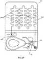
- FIG. 5is a plan view of an illustrative test cartridge of the type that does not include reagents
- FIG. 6is a perspective view of an illustrative reagent supply module showing a test cartridge ready to be joined with the module;
- FIG. 7Ais a perspective bottom view of a metering chamber formed in the face of a valve stem of a rotary valve
- FIG. 7Bis a side view of a valve stem with a metering chamber formed as a pass-through conduit;
- FIG. 8Ais a plan view of an illustrative test cartridge showing a sample of whole blood deposited in the input port area;
- FIG. 8Bis a plan view of the test cartridge of FIG. 8A showing initial movement of the sample and reagent with the rotary valve in the first open position;
- FIG. 8Cis a plan view of the test cartridge of FIG. 8B with the valve in the second open position;
- FIG. 8Dis a plan view of the test cartridge of FIG. 8C illustrating the sample and the reagent in the imaging chamber;
- FIG. 8Eis a plan view of the test cartridge of FIG. 8D illustrating the sample and most of the reagent positioned in the mixing chamber;
- FIG. 8Fis a plan view of the test cartridge of FIG. 8E illustrating all of the sample and the reagent positioned in the imaging chamber and the valve in a final, closed position;
- FIG. 9is an side elevation view of a cross section of the passive mixing chamber taken through line 9 - 9 ′ of FIG. 8E ;
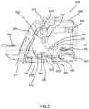
- FIG. 10is a plan view of a test cartridge of an alternate test cartridge embodiment.
- FIG. 11is a flowchart illustrating the operation of the cell analyzer.
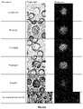
- FIGS. 12A and 12Bshow both bright-field and fluorescent images of the same cells that were collected according to the present invention.
- FIG. 1illustrates test cartridge 100 being positioned to collect a drop of blood 120 from a patient's finger.
- the test cartridgeis held beneath the hanging drop 120 , so that it contacts the input port 130 of the test cartridge 100 .
- the input port 130comprises a recessed area or opening that may be coated with an anticoagulant and have surface treatment or features such as small columns to increase surface retention to collect and hold the blood sample.
- the blood sample 120may be collected intravenously and introduced to input port 130 by a transfer pipette or capillary tube.
- the transfer pipette or capillarymay contain an anticoagulant coating according to the desired workflow.
- the volume of blood or other biological sample placed in input port 130is sufficient to visually fill the recessed sample area, but is unmeasured.
- FIG. 2Ashows test cartridge 100 with closure 135 shown in the open position to provide access to input port 130 .
- Closure 135is adapted to slide relative to the test cartridge 100 and may have detent or other positioning features that facilitate placing it in different positions.
- closure 135may be moved to the position shown in FIG. 2B to cover the input port 130 .
- the closure 135may be moved by the user prior to inserting it into the analyzer as shown in FIG. 3 .
- closure 135may be moved by an operation within the cell analyzer.
- Alternate embodiments of closure 135may include graphics, identifying information, or instructions to the user.
- closure 135is illustrated as a sliding component, other means of closing the input port 130 are contemplated including a cap that hinges upward, a small surface cover that swivels away from and returns to cover the input port 130 , or an adhesive component that sticks to the input port 130 or area surrounding it. In all cases the closure 135 includes a vent or air path to the input port to allow the blood sample to move into the test cartridge 100 .
- FIG. 3is a cut-away view of an illustrative cell analyzer 200 with test cartridge 100 positioned so that the operator can introduce it into the analyzer. From the outside of the cell analyzer 200 , one can see the housing 206 , a user-interface screen 208 , a printer 212 , and a cartridge loading door 217 . When the cartridge loading door 217 is opened, the test cartridge 100 can be placed on a cradle 220 of x-y stage 225 , configured to receive test cartridge 100 from the user. The cradle 220 provides mechanical alignment of the cartridge to facilitate connections that are made between the analyzer and the cartridge.
- a mechanical presser foot 230may be placed in contact with a flexible surface on the test cartridge to provide mechanical pressure onto packaged, on-board reagents.
- Some embodiments of the cell analyzer 200may utilize a reagent supply module 470 as further described with reference to FIG. 6 .
- Reagent supply module 470may be installed on x-y stage 225 and has a receiving area 473 (see FIG. 6 ) to provide alignment of the test cartridge 402 with the reagent module 470 .
- a valve driver 235can be positioned to operate a rotary valve on the test cartridge.
- a vacuum/pressure pump 240supplies negative or positive pressure to a manifold 245 , which interfaces with the test cartridge 100 when it is placed in the cell analyzer as described below.
- the cell analyzer 200further includes system controller 250 to control movement of the fluids in the test cartridge by activating the vacuum/pressure pump 240 , moving the mechanical presser foot 230 , or operating the valve driver 235 according to pre-programmed sequences.
- Monitoring camera 255positioned to acquire digital images of the fluids in the cartridge, provides feedback for the system controller 250 .
- Monitoring light source 256may be a ring illuminator that surrounds the lens of the monitoring camera 255 . Information from the monitoring camera 255 is used to provide feedback for controlling movement of liquids, for positioning the rotary valve, and for confirming critical steps.
- the components that comprise the automated microscope of the cell analyzer 200are shown in FIG. 3 .
- bright-field light source 260provides illumination through the test cartridge to the objective lens 265 , operatively coupled to focusing mechanism 267 .
- fluorescent light source 270provides illumination through dichroic mirror 277 to provide fluorescent excitation of the sample.
- digital camera 280captures images of the test cartridge 100 and transmits them to image processor/computer 290 .
- the cell analyzermay further include a photometric light source 293 and photometric detector 295 for measuring light transmission at one or multiple wavelengths in a chamber in test cartridge 100 , such as for measuring hemoglobin, as is more fully explained below.
- FIG. 4shows an illustrative test cartridge 401 of the type that includes liquid reagents stored in a blister pack 417 for conducting a test.
- the test cartridge 401has an input port 407 for receiving a sample, a passive mixing chamber 405 for mixing the sample with diluent/reagent, and an imaging chamber 403 for capturing images of the cells in the mixture of sample and diluent/reagent for analysis.
- photometric chamber 409may be filled with whole blood to make optical absorbance measurements to determine concentrations of certain analytes in the sample, such as hemoglobin.
- a rotary valve 415provides fluidic connections between various fluidic channels, vents, and ports, including sample driver port 411 , vent 423 and mixture driver port 429 as will be described in FIGS. 8A-8F .
- FIG. 5shows an illustrative test cartridge 402 of the type that does not include on-board diluent/reagents.
- test cartridge 402has a reagent input port 460 adapted to be connected to an external source of diluent/reagent.
- Test cartridge 402may be used in embodiments in which diluent/reagents that are needed for an analysis may be too costly to package individually or may require refrigerated storage.
- diluent/reagentmay be provided from a source within cell analyzer 200 or from a reagent supply module.
- FIG. 6shows an illustrative reagent supply module 470 positioned to receive test cartridge 402 .
- the reagent supply module 470includes a receiving area 473 for docking the test cartridge 402 , and contains a vessel for holding the diluent/reagent, a reagent metering pump adapted to pump the diluent/reagent, and a reagent output port 475 .
- the reagent output port 475is constructed with a suitable shape and/or elastomeric materials to insure a liquid-tight connection to reagent input port 460 on the test cartridge 402 , when the test cartridge is docked to the reagent supply module 470 .
- Reagent supply module 470has an opening 477 suitably sized to allow monitoring camera 255 ( FIG. 3 ) to image the rotary valve 415 . Additionally a window 478 in the reagent supply module 470 is constructed to align with the photometric chamber 409 in the test cartridge. Window 478 allows the photometric light source 293 and photometric detector 295 ( FIG. 3 ) to make optical absorbance measurements on the fluid within photometric chamber 409 .
- the size of the vessel within reagent supply module 470is of sufficient capacity to provide diluent/reagents to dilute and/or stain from ten to about one-hundred samples with a diluent/reagent to sample ratio of 10:1 to about 250:1.
- the reagent supply module 470further can include a self-priming mechanism for priming the liquid reagent and eliminating air bubbles.
- the reagent supply module 470may include a chamber for collecting waste reagent from the priming process.
- the vacuum/pressure pump 240makes connections through manifold 245 to sample driver port 411 and mixture driver port 429 .
- the interfaces between the manifold 245 and these portsare constructed with a suitable shape and/or elastomeric material to ensure an airtight connection so that system controller 250 can control movement of the fluids in the test cartridge (see FIG. 3 ).
- the presser foot 230is not needed.
- FIG. 7Ashows the face of a cylindrical valve stem 485 of a rotary face valve.
- Metering chamber 483is formed in the face by highly precise manufacturing processes such as injection molding.
- the chamber 483is narrow and tubular in shape and centered in the face of the cylindrical stem 485 .
- a slot 487 in the top of stem 485acts as a valve indexer to indicate the position of the valve stem 485 .
- auxiliary connector 421which has a circular shape.
- metering chamber 483When assembled into the rotary valve 415 ( FIGS. 4 and 5 ), metering chamber 483 is able to connect between ports in the valve which are 180 degrees apart, while auxiliary connector 421 connects between other ports which are 60 degrees apart.
- system controller 250is able to control movement of the fluids by rotating valve stem 485 and by positioning the valve according to the valve indexer 487 according to preprogrammed sequences.
- the metering chamber 483can be connected to the input port 407 ( FIG. 4 and FIG. 5 ) and filled with the biological sample, and then by rotating valve stem 485 , the volume contained within metering chamber 483 can be isolated and transferred for analysis.
- FIG. 7Bis a side view of a valve stem 485 ′ with a metering chamber formed as a pass-through conduit 413 in the tapered seat of valve stem 485 ′.
- Pass-through conduit 413is able to connect with fluidic channels in rotary valve 415 which are 180 degrees apart.
- auxiliary fluidic connector 421 ′which provides connections to adjacent fluidic channels which are 60 degrees apart.
- pass-through conduit 413When assembled in the rotary valve 415 ( FIG. 4 and FIG. 5 ) having a tapered seat to receive valve stem 485 ′, pass-through conduit 413 can be connected to input port 407 ( FIG. 4 and FIG. 5 ), filled with the biological sample, and then by rotating valve stem 485 ′, the volume of sample contained within pass-through conduit 413 can be isolated and transferred for analysis.
- FIG. 7Balso shows auxiliary fluidic connector 421 ′, which provides fluidic connections to adjacent fluidic channels on the test cartridge according to the position of the valve indexer 487 ′.
- the rotary face valve of FIG. 7A and the tapered seat valve of FIG. 7Bare alternate embodiments for isolating sample and controlling fluidic paths. Therefore, in the descriptions that follow references to metering chamber 483 in a rotary face valve will be equally applicable to pass-through conduit 413 in a tapered seat valve.
- FIGS. 8A through 8Fa sequence of operations will be illustrated that enable cell analyzer 200 to perform automated microscopic cell analysis on a biological sample without skilled operator interactions.
- a sampleis shown deposited into input port 407 , which is in fluid communication with rotary valve 415 .
- the stem 485 ( FIG. 7A ) of rotary valve 415is in a first position wherein the metering chamber 483 ( FIG. 7A ) is aligned with the sample input port 407 and the sample driver port 411 .
- a vacuumsupplied by the analyzer to sample driver port 411 , draws the sample from the input port 407 into the metering chamber 483 and into the photometric chamber 409 .
- the system controller 250collects absorbance data from the undiluted sample using the photometric light source 293 ( FIG. 3 ) and photometric detector 295 ( FIG. 3 ).
- suitable choice of optical wavelengths and chamber geometry and analysis of the light passing through the biological samplecan be used to determine concentrations of certain analytes in the sample such as hemoglobin.
- cartridge 401is shown with a diluent/reagent contained in a blister pack 417 .
- auxiliary connector 421provides a fluid communication path between the blister pack 417 and vent 423 .
- pressureis applied to the blister pack 417 by presser foot 230 ( FIG. 3 )
- diluent/reagentis released and flushed through auxiliary connecter 421 thereby priming the channels and removing air bubbles through vent 423 .
- FIG. 8Cshows rotary valve 415 turned counterclockwise 60 degrees to a second position, which isolates a predetermined amount of sample in the metering chamber 483 .
- the stem 485 of rotary valve 415is positioned such that the metering chamber 483 is in fluid communication with blister pack 417 and the serpentine imaging chamber 403 .
- FIG. 8Dthe rotary valve 415 is shown in the same position as in FIG. 8C but following operation of the presser foot 230 which applies pressure to the blister pack 417 .
- the diluent/reagent from blister pack 417 and the isolated sample 493 from the metering chamber 483are transferred into the imaging chamber 403 .
- a minimum volume of reagent of three times the volume of the pass-through conduit 413is needed to flush the entire sample from the rotary valve 415 .
- a sufficient volume of the reagentis pushed through the rotary valve 415 to completely wash out the isolated sample and to achieve the approximate dilution ratio desired.
- FIG. 8Ethe rotary valve 415 is shown turned counterclockwise 120 degrees from its previous position shown in FIG. 8D to its third position, wherein auxiliary connector 421 is aligned with mixture driver port 429 and imaging chamber 403 .
- Vacuum/pressure pump 240 of cell analyzer 200( FIG. 3 ) supplies pressure to mixture driver port 429 and pushes all of the mixture of sample and diluent/reagent from the imaging chamber 403 into passive mixing chamber 405 .
- air within the chamberis vented through vent port 433 .
- vacuum/pressure pump 240applies a controlled vacuum to mixture driver port 429 such that the mixture is pulled back into the imaging chamber 403 .
- a preprogrammed sequence of pushing the mixture into the passive mixing chamber 405 and pulling it back into the imaging chamber 403is repeated to achieve a final mixture 495 that is free from cell clumping and overlapping after the cells settle to the bottom of the imaging chamber 403 .
- the final movement of the mixture 495it is positioned entirely within the imaging chamber 403 as illustrated in FIG. 8F .
- mixing chamber 405could be located at the beginning of the imaging chamber 403 .
- FIG. 8Fillustrates the final step of the sample preparation sequence.
- the entire final mixture 495has been withdrawn from the passive mixing chamber 405 and is positioned in the imaging chamber 403 .
- the rotary valve 415is rotated counterclockwise approximately 30 degrees to the position shown in FIG. 8F , whereby it is not in fluid communication with any fluidic channel in rotary valve 415 , thereby blocking further fluid communication with the imaging chamber 403 so that no further movement of the final mixture 495 can take place.
- FIG. 9shows a cross section of the passive mixing chamber 405 .
- the chamberis referred to as “passive” because as illustrated, it does not contain any active mixing element such as a bead or spin-bar.
- active mixing elementsuch as a bead or spin-bar.
- Such devicesmay be used in some embodiments, but we have found that an adequately sized chamber as depicted in FIG. 9 is simpler and provides excellent mixing of the sample and reagent.
- the diluent/reagent and sample 493are driven by vacuum/pressure pump 240 ( FIG. 3 ) and enter and exit the chamber through mixing chamber opening 497 . As liquid enters the chamber, air within the chamber escapes through vent port 433 .
- the cross section of passive mixing chamber 405illustrates wall geometry that increases smoothly in size from the bottom to the top such that the mixture entering from below expands into a larger volume.
- the chamber 405may have asymmetrical sloped walls 484 and 491 to promote mixing of the sample and reagent and for removing bubbles from the mixture. After all of the mixture is in the chamber, air bubbles may be introduced to the chamber by vacuum/pressure pump 240 through mixing chamber opening 497 . These air bubbles further promote mixing and subsequently escape through vent port 433 .
- the choice of materials used to fabricate the passive mixing chamber 405should take into consideration the wetting properties of the specific 1 diluent/reagent(s) being utilized in the test cartridge 401 . The properties of the material, among other requirements, should ensure that liquid surface tension will pull back all of the liquid in contact with the side walls of the chamber when the vacuum/pressure pump 240 empties the chamber through mixing chamber opening 497 .
- FIG. 10illustrates test cartridge 400 which comprises an imaging chamber 403 having at one end a sample input port 450 , and at the opposite end a vent 453 .
- a user of test cartridge 400collects a small known volume of whole blood and mixes it manually with a diluent/reagent in a separate single-use sample preparation device (not shown). Once mixed, the entire mixed volume is injected into sample input port 450 . Air escapes through vent 453 as the mixture is injected allowing the sample to fill the imaging chamber 403 .
- the imaging chamberis essentially the same imaging chamber as described above and shown in FIGS. 8A-8F .
- Test cartridge 400can be placed into analyzer 200 ( FIG. 3 ) for analysis beginning at step 560 of FIG. 11 as described below.
- cell analyzer 200configured to provide a “CBC with Differential” analysis with reference to the test cartridge 401 illustrated in FIGS. 8A-8F and cell analyzer 200 illustrated in FIG. 3 .
- the userTo obtain the blood sample from a patient presented at box 500 , the user first obtains a new test cartridge 401 at box 505 and opens it to expose the input port 407 . Blood from a finger prick is applied as illustrated in FIG. 1 at box 510 and the input port 407 is covered. The user inserts the test cartridge into the cell analyzer 200 at box 515 . The test cartridge is moved into the analyzer where mechanical and fluid connections are made between the analyzer and the cartridge as described above with reference to FIG. 3 .
- the sampleis drawn into the metering chamber passing through and into photometric chamber 409 ( FIG. 8A ).
- Absorbance of the bloodis measured at box 520 .
- Data from absorbance measurementsare used to determine hemoglobin concentration.
- sample in the metering chamber 483is imaged using monitoring camera 255 and analyzed to confirm that the metering chamber was properly filled at box 535 . If an error is detected the analysis is terminated at box 537 and the user is alerted to the error and instructed to remove the cartridge and reject the test.
- rotary valve 415is positioned as shown in FIG. 8E and the total volume of sample and diluent/reagent is mixed at box 550 .
- the entire volume 495is transferred to the imaging chamber and rotary valve 415 is positioned as shown in FIG. 8F . Note that by transferring the entire volume of mixed sample 495 , all of the metered volume of blood from the original sample plus the unmetered volume of diluent/reagent is positioned in the imaging chamber at box 555 .
- test cartridge 400If test cartridge 400 is used, it is inserted into cell analyzer 200 and analysis begins at step 560 . Analysis of test cartridge 401 or 402 continues at step 560 when the x-y stage 225 moves the test cartridge 401 to obtain bright-field and fluorescent images of the entire imaging chamber 403 at box 560 .
- objective lens 265 and/or digital camera 280are moved and test cartridge 401 remains stationary.
- objective lens 265has sufficient field of view to capture the entire imaging chamber 403 without movement.
- Two digital images of each physical frame of the imaging chamberare transferred to image processor/computer 290 at box 565 . One image, taken with bright-field optics, can be compared to the other image taken with fluorescent optics to identify red blood cells, white blood cells and platelets. Further analysis of the white cell sizes and internal structure can identify sub-types of white cells using pattern recognition.
- comparison of the bright-field and fluorescent imagescan differentiate mature red cells from reticulocytes and nucleated red blood cells.
- concentrationcells per unit volume
- MCVmean corpuscular volume
- RDWred cell distribution width
- the measured resultsare compared with previously defined limits and ranges for the particular patient population and determination is made whether the results are within or outside normal expected ranges. According to this determination results within normal ranges are reported in box 580 and results that are outside the normal ranges are reported in box 585 .
- FIG. 12shows images that were collected using test devices according to the present invention.
- a fluorescent stain Acridine Orange (AO)was used to differentially stain DNA and RNA of cells in a whole blood sample.
- the visual images of FIG. 12were obtained using an Olympus 20X ⁇ 0.4 NA objective lens 265 and a Basler 5 MP digital camera 280 .
- Excitation of the bright-field images in the second columnwas provided by white light bright-field source 260 .
- Excitation of the fluorescent images in the third columnwas a 455 nm blue fluorescent light source 270 .
- White blood cellshave significant RNA and DNA and therefore can be seen in the fluorescent images having green and orange structures.
- the size and shape of the green nuclear structure and overall size of the white cellscan be used to differentiate them into sub-groups identified by name in the first column.
- the basophil and eosinophil sub-groups of white cellshave characteristic features in the bright-field image due to the presence of large granules in the cytoplasm. Therefore embodiments of the present invention make use of both bright-field and fluorescent image analysis to differentiate sub-groups of white cells.
- Plateletsalso take up the AO stain but the size of a platelet is significantly smaller than any white cell and can therefore be differentiated. Because red cells lose their nucleus as they mature, they do not have nuclear material to take up the AO stain. Consequently the red cells can be identified as the objects that appear in the bright-field and cannot be seen in the fluorescent field.
- the immature red cellscalled reticulocytes and the nucleated red blood cells (nRBC) have attributes of red cells but also show small levels of fluorescence. Embodiments of the present invention make use of these combined attributes to identify and sub-group red blood cells.
- Table 1illustrates a comparison of CBC parameters obtained according to the present invention and from an automated hematology analyzer.
Landscapes
- Health & Medical Sciences (AREA)
- Life Sciences & Earth Sciences (AREA)
- Engineering & Computer Science (AREA)
- Chemical & Material Sciences (AREA)
- Biomedical Technology (AREA)
- Physics & Mathematics (AREA)
- Immunology (AREA)
- Hematology (AREA)
- General Health & Medical Sciences (AREA)
- Analytical Chemistry (AREA)
- General Physics & Mathematics (AREA)
- Molecular Biology (AREA)
- Biochemistry (AREA)
- Pathology (AREA)
- Urology & Nephrology (AREA)
- Medicinal Chemistry (AREA)
- Food Science & Technology (AREA)
- Dispersion Chemistry (AREA)
- Cell Biology (AREA)
- Ecology (AREA)
- Biophysics (AREA)
- Biotechnology (AREA)
- Microbiology (AREA)
- Clinical Laboratory Science (AREA)
- Chemical Kinetics & Catalysis (AREA)
- Multimedia (AREA)
- Theoretical Computer Science (AREA)
- Tropical Medicine & Parasitology (AREA)
- Signal Processing (AREA)
- Investigating Or Analysing Biological Materials (AREA)
- Computer Vision & Pattern Recognition (AREA)
Abstract
Description
| TABLE 1 | |||||||||
| Column1 | # pairs | RBCs | WBCs | ROI | RBC/f | RBC/f(%)- | WBC/f | WBC/f(%) | RBC/ |
| 100% | 9916 | 2455492 | 5125 | 3818.7 | 643.02 | 100.0 | 1.342 | 100.0 | 479.12 |
| 50% | 4958 | 1229669 | 2535 | 1913.7 | 642.56 | 99.9 | 1.325 | 98.7 | 485.08 |
| 25% | 2479 | 623048 | 1285 | 968.5 | 643.28 | 100.0 | 1.327 | 98.9 | 484.86 |
| 10% | 992 | 242197 | 519 | 373.5 | 648.48 | 100.8 | 1.390 | 103.5 | 466.66 |
| 5% | 496 | 126186 | 262 | 197.2 | 639.82 | 99.5 | 1.328 | 99.0 | 481.63 |
| 1% | 100 | 23683 | 63 | 35.6 | 664.61 | 103.4 | 1.768 | 131.7 | 375.92 |
Sample: Low WBC count—approximately 2000/uL (normal is 3,000-10,000/uL).
Magnification: 20×
Number of images: approximately 10,000 bright-field and 10,000 fluorescent
Variable: Column 1—Percentage of total cells use in the calculation
Column # pairs—the number of pairs of images (bright-field plus fluorescent)
Column RBCs—total number of Red Blood Cells counted
Column WBCs—total number of White Blood Cells counted
Column ROI—total Region of Interest. This is the ‘effective’ number of image frames occupied by actual sample. A frame totally filled with sample/cells is “1”. A partial frame (due to an edge or the curved ends of the serpentine shape), is a fraction of a frame (e.g. 0.567).
Column RBC/f—Average number of Red Blood Cells per frame (Column RBCs divided by Column 5 ROI).
Column RBC/f (%)—This is the RBC/frame value at a particular sampling percentage divided by the RBC/frame for the 100% sampling case (top line). This is an estimate of the accuracy of the particular sampling percentage compared to counting 100% of the cells.
Column WBC/f—Average number of White Blood Cells per frame (Column WBCs divided by Column ROI).
Column RBC/WBC—This is the ratio of RBC/WBC for the particular sampling percentage.
Results: A small percentage of the total frames can provide accurate results. As a smaller fraction of the total frames are counted, the accuracy is maintained down to 1% for Red Blood Cells and down to 5% for White Blood Cells.
Discussion: In these experiments, it took approximately one second to capture an image pair. For this experiment, where almost 10,000 image pairs were needed to capture 100% of the sample, this means that image analysis took 10,000 seconds or approximately 2.8 hours. The experiment shows that the uniformity of the distribution of cells across the imaging chamber was good enough to provide accurate results by counting cells in only 5% of the frames. The goal of “counting every cell” is achieved because the entire sample size (the Region of Interest ROI) is measured, but only 5% of the images need to be analyzed to get accurate results. This reduces the image analysis time to approximately 8 minutes. It is expected that advances in camera and computer processing technology will further reduce this time.
Claims (37)
Priority Applications (8)
| Application Number | Priority Date | Filing Date | Title |
|---|---|---|---|
| US15/017,498US11478789B2 (en) | 2014-11-26 | 2016-02-05 | Automated microscopic cell analysis |
| US15/221,285US9767343B1 (en) | 2014-11-26 | 2016-07-27 | Automated microscopic cell analysis |
| US15/616,327US10625259B1 (en) | 2014-11-26 | 2017-06-07 | Automated microscopic cell analysis |
| US16/235,099US12005441B1 (en) | 2014-11-26 | 2018-12-28 | Automated microscopic cell analysis |
| US16/803,897US11590496B2 (en) | 2014-11-26 | 2020-02-27 | Automated microscopic cell analysis |
| US17/972,469US20230294089A1 (en) | 2014-11-26 | 2022-10-24 | Automated microscopic cell analysis |
| US18/114,754US12337315B2 (en) | 2014-11-26 | 2023-02-27 | Automated microscopic cell analysis |
| US19/029,288US20250249449A1 (en) | 2014-11-26 | 2025-01-17 | Automated microscopic cell analysis |
Applications Claiming Priority (5)
| Application Number | Priority Date | Filing Date | Title |
|---|---|---|---|
| US201462084760P | 2014-11-26 | 2014-11-26 | |
| US201562113360P | 2015-02-06 | 2015-02-06 | |
| US201562138359P | 2015-03-25 | 2015-03-25 | |
| US14/947,971US20170328924A1 (en) | 2014-11-26 | 2015-11-20 | Automated microscopic cell analysis |
| US15/017,498US11478789B2 (en) | 2014-11-26 | 2016-02-05 | Automated microscopic cell analysis |
Related Parent Applications (1)
| Application Number | Title | Priority Date | Filing Date |
|---|---|---|---|
| US14/947,971Continuation-In-PartUS20170328924A1 (en) | 2014-11-26 | 2015-11-20 | Automated microscopic cell analysis |
Related Child Applications (3)
| Application Number | Title | Priority Date | Filing Date |
|---|---|---|---|
| US15/221,285ContinuationUS9767343B1 (en) | 2014-11-26 | 2016-07-27 | Automated microscopic cell analysis |
| US16/235,099ContinuationUS12005441B1 (en) | 2014-11-26 | 2018-12-28 | Automated microscopic cell analysis |
| US17/972,469ContinuationUS20230294089A1 (en) | 2014-11-26 | 2022-10-24 | Automated microscopic cell analysis |
Publications (2)
| Publication Number | Publication Date |
|---|---|
| US20170326549A1 US20170326549A1 (en) | 2017-11-16 |
| US11478789B2true US11478789B2 (en) | 2022-10-25 |
Family
ID=59828534
Family Applications (3)
| Application Number | Title | Priority Date | Filing Date |
|---|---|---|---|
| US15/017,498Active2035-12-13US11478789B2 (en) | 2014-11-26 | 2016-02-05 | Automated microscopic cell analysis |
| US15/221,285ActiveUS9767343B1 (en) | 2014-11-26 | 2016-07-27 | Automated microscopic cell analysis |
| US17/972,469PendingUS20230294089A1 (en) | 2014-11-26 | 2022-10-24 | Automated microscopic cell analysis |
Family Applications After (2)
| Application Number | Title | Priority Date | Filing Date |
|---|---|---|---|
| US15/221,285ActiveUS9767343B1 (en) | 2014-11-26 | 2016-07-27 | Automated microscopic cell analysis |
| US17/972,469PendingUS20230294089A1 (en) | 2014-11-26 | 2022-10-24 | Automated microscopic cell analysis |
Country Status (1)
| Country | Link |
|---|---|
| US (3) | US11478789B2 (en) |
Cited By (2)
| Publication number | Priority date | Publication date | Assignee | Title |
|---|---|---|---|---|
| US11590496B2 (en) | 2014-11-26 | 2023-02-28 | Medica Corporation | Automated microscopic cell analysis |
| US12005441B1 (en) | 2014-11-26 | 2024-06-11 | Medica Corporation | Automated microscopic cell analysis |
Families Citing this family (32)
| Publication number | Priority date | Publication date | Assignee | Title |
|---|---|---|---|---|
| US9522396B2 (en) | 2010-12-29 | 2016-12-20 | S.D. Sight Diagnostics Ltd. | Apparatus and method for automatic detection of pathogens |
| BR112014016072B1 (en) | 2011-12-29 | 2021-01-12 | Sight Diagnostics Ltd. | method and system for detecting a plasmodium infection in a blood sample |
| EP2999988A4 (en) | 2013-05-23 | 2017-01-11 | S.D. Sight Diagnostics Ltd. | Method and system for imaging a cell sample |
| IL227276A0 (en) | 2013-07-01 | 2014-03-06 | Parasight Ltd | A method and system for preparing a monolayer of cells, particularly suitable for diagnosis |
| US10831013B2 (en) | 2013-08-26 | 2020-11-10 | S.D. Sight Diagnostics Ltd. | Digital microscopy systems, methods and computer program products |
| EP3186778B1 (en) | 2014-08-27 | 2023-01-11 | S.D. Sight Diagnostics Ltd. | System and method for calculating focus variation for a digital microscope |
| US11478789B2 (en)* | 2014-11-26 | 2022-10-25 | Medica Corporation | Automated microscopic cell analysis |
| US20170328924A1 (en) | 2014-11-26 | 2017-11-16 | Ronald Jones | Automated microscopic cell analysis |
| EP3350644B1 (en) | 2015-09-17 | 2021-04-28 | S.D. Sight Diagnostics Ltd. | Methods and apparatus for detecting an entity in a bodily sample |
| CA3018536A1 (en) | 2016-03-30 | 2017-10-05 | S.D. Sight Diagnostics Ltd | Distinguishing between blood sample components |
| JP6942148B2 (en) | 2016-05-11 | 2021-09-29 | エス.ディー.サイト ダイアグノスティクス リミテッド | Performing optical measurements on the sample |
| EP4177593A1 (en) | 2016-05-11 | 2023-05-10 | S.D. Sight Diagnostics Ltd. | Sample carrier for optical measurements |
| JP2019526288A (en)* | 2016-09-14 | 2019-09-19 | ブイビーシー ホールディングス エルエルシー | System, apparatus, and method for optimizing cell growth by controlling cell culture operations |
| USD833641S1 (en)* | 2017-01-24 | 2018-11-13 | Life Technologies Corporation | Capillary electrophoresis cartridge in a container |
| CN110475613A (en)* | 2017-02-06 | 2019-11-19 | Efa-全部取向工程公司 | Portable digital diagnostic device |
| US11067526B2 (en) | 2017-08-17 | 2021-07-20 | Abbott Point Of Care Inc. | Devices, systems, and methods for performing optical and electrochemical assays |
| AU2018369859B2 (en) | 2017-11-14 | 2024-01-25 | S.D. Sight Diagnostics Ltd | Sample carrier for optical measurements |
| US11047845B1 (en)* | 2017-11-15 | 2021-06-29 | Medica Corporation | Control material and methods for cell analyzers |
| US10094759B1 (en)* | 2017-12-22 | 2018-10-09 | Hillel Llc | Imaging device for measuring sperm motility |
| JPWO2019131626A1 (en)* | 2017-12-28 | 2020-12-10 | オリンパス株式会社 | Cell culture control method, cell culture control device, cell culture device and cell culture system |
| CN111487179B (en)* | 2019-01-29 | 2024-09-20 | 华中师范大学 | Portable blood cell counting kit |
| EP3751289A1 (en)* | 2019-06-13 | 2020-12-16 | Siemens Healthcare Diagnostics Products GmbH | Device for optically monitoring a dosing of a liquid to be pipetted |
| US11327084B2 (en)* | 2019-09-19 | 2022-05-10 | Invidx Corp. | Joint hematology and biochemistry point-of-care testing system |
| WO2021116959A1 (en) | 2019-12-12 | 2021-06-17 | S.D. Sight Diagnostics Ltd | Analyzing an analyte disposed within a medium |
| EP4073566B1 (en) | 2019-12-12 | 2025-04-23 | S.D. Sight Diagnostics Ltd. | Artificial generation of color blood smear image |
| WO2021161171A1 (en)* | 2020-02-10 | 2021-08-19 | Yuk Lun Tsang | Point-of-care microfluidic in vitro diagnostic system |
| JP7413104B2 (en)* | 2020-03-17 | 2024-01-15 | 京セラ株式会社 | Inspection system, program and inspection method |
| WO2022107132A1 (en)* | 2020-11-17 | 2022-05-27 | Scopio Labs Ltd. | Detecting scan area within hematology slides in digital microscopy |
| IT202100021401A1 (en)* | 2021-08-20 | 2023-02-20 | Giuseppe Piccinni | IgG/IgM serological rapid test |
| US11906433B2 (en)* | 2021-12-14 | 2024-02-20 | Instituto Potosino de Investigación Científica y Tecnológica A.C. | System and method for three-dimensional imaging of unstained samples using bright field microscopy |
| WO2024159226A2 (en)* | 2023-01-28 | 2024-08-02 | The General Hospital Corporation | Systems and methods for high-efficiency microfluidic analysis of blood |
| WO2024192493A1 (en)* | 2023-03-22 | 2024-09-26 | Hi Technologies Ltda. | Biological sample analyser for microscopy and spectrometry |
Citations (97)
| Publication number | Priority date | Publication date | Assignee | Title |
|---|---|---|---|---|
| US3756783A (en) | 1971-08-23 | 1973-09-04 | M Willams | Automatic clinical chemistry analyzer |
| US4706207A (en) | 1985-06-24 | 1987-11-10 | Nova Celltrak, Inc. | Count accuracy control means for a blood analyses system |
| US5352585A (en)* | 1993-06-29 | 1994-10-04 | Bio-Rad Laboratories, Inc. | System for benzodiazepine detection |
| US5464752A (en) | 1987-03-13 | 1995-11-07 | Coulter Corporation | Automated analyzer for screening cells or formed bodies for enumeration of populations expressing selected characteristics |
| US5469251A (en) | 1992-06-12 | 1995-11-21 | Toa Medical Electronics Co., Ltd. | Apparatus for detecting fluorescence of particles in a fluid and analyzing the particles |
| US5486335A (en) | 1992-05-01 | 1996-01-23 | Trustees Of The University Of Pennsylvania | Analysis based on flow restriction |
| US5891734A (en) | 1994-08-01 | 1999-04-06 | Abbott Laboratories | Method for performing automated analysis |
| WO1999052633A1 (en) | 1998-04-14 | 1999-10-21 | Ivd Systems | Test cartridge with a single inlet port |
| US6082185A (en) | 1997-07-25 | 2000-07-04 | Research International, Inc. | Disposable fluidic circuit cards |
| US6235536B1 (en) | 1998-03-07 | 2001-05-22 | Robert A. Levine | Analysis of quiescent anticoagulated whole blood samples |
| US6251615B1 (en) | 1998-02-20 | 2001-06-26 | Cell Analytics, Inc. | Cell analysis methods |
| US20020028471A1 (en) | 1998-02-20 | 2002-03-07 | Oberhardt Bruce J. | Cell analysis methods and apparatus |
| WO2002089670A1 (en) | 2001-05-10 | 2002-11-14 | Chempaq A/S | Device for sampling small and precise volumes of liquid |
| US20030133119A1 (en) | 2002-01-17 | 2003-07-17 | Bachur Nicholas R. | Rapid imaging of particles in a large fluid volume through flow cell imaging |
| US20030159999A1 (en)* | 2002-02-04 | 2003-08-28 | John Oakey | Laminar Flow-Based Separations of Colloidal and Cellular Particles |
| US6656683B1 (en) | 2000-07-05 | 2003-12-02 | Board Of Regents, The University Of Texas System | Laser scanning cytology with digital image capture |
| US20040086427A1 (en) | 2002-10-31 | 2004-05-06 | Childers Winthrop D. | Microfluidic system utilizing thin-film layers to route fluid |
| WO2004045770A1 (en) | 2002-11-20 | 2004-06-03 | Boule Medical Ab | Blood testing apparatus |
| US6811668B1 (en) | 1999-06-22 | 2004-11-02 | Caliper Life Sciences, Inc. | Apparatus for the operation of a microfluidic device |
| US20050003554A1 (en) | 2003-05-09 | 2005-01-06 | Caliper Technologies Corp. | Automated sample analysis |
| US20050005684A1 (en) | 2000-02-23 | 2005-01-13 | Caliper Life Sciences, Inc. | Multi-reservoir pressure control system |
| US20050186114A1 (en) | 2002-04-15 | 2005-08-25 | Kurt Reinhardt | Automated high volume slide processing system |
| WO2005114144A1 (en) | 2004-05-14 | 2005-12-01 | Honeywell International, Inc. | Portable sample analyzer cartridge |
| US20060094109A1 (en) | 2004-11-02 | 2006-05-04 | Immunivest Corporation | Device and method for analytical cell imaging |
| US20060240545A1 (en) | 2005-04-26 | 2006-10-26 | Moritex Corporation | Flow cell and a reactor for reactions between fixed reacting substances and liquid reacting substances, and a method for operating the reactor |
| WO2006113727A2 (en) | 2005-04-19 | 2006-10-26 | President And Fellows Of Harvard College | Fluidic structures including meandering and wide channels |
| WO2007005907A1 (en) | 2005-07-01 | 2007-01-11 | Honeywell International, Inc. | A molded cartridge with 3-d hydrodynamic focusing |
| US20070076190A1 (en) | 2005-09-28 | 2007-04-05 | Sysmex Corporation | Apparatus for obtaining an image of a blood cell and method for obtaining an image of a blood cell |
| US20070166195A1 (en) | 2004-05-14 | 2007-07-19 | Honeywell International Inc. | Analyzer system |
| US20080014589A1 (en)* | 2006-05-11 | 2008-01-17 | Link Darren R | Microfluidic devices and methods of use thereof |
| CN100392403C (en) | 2005-12-09 | 2008-06-04 | 天津理工大学 | A method for automatically counting the number of white blood cells in blood microscopic images |
| US20090123337A1 (en) | 2005-06-24 | 2009-05-14 | Arkray,Inc | Cartridge |
| US7553453B2 (en) | 2000-06-02 | 2009-06-30 | Honeywell International Inc. | Assay implementation in a microfluidic format |
| US20090215072A1 (en) | 2005-05-31 | 2009-08-27 | The Board Of Regents Of The University Of Texas System | Methods and compositions related to determination and use of white blood cell counts |
| US20090269799A1 (en) | 2008-04-25 | 2009-10-29 | Constitutional Medical Investors, Inc. | Method of determining a complete blood count and a white blood cell differential count |
| US7738094B2 (en) | 2007-01-26 | 2010-06-15 | Becton, Dickinson And Company | Method, system, and compositions for cell counting and analysis |
| US7764821B2 (en) | 2002-02-14 | 2010-07-27 | Veridex, Llc | Methods and algorithms for cell enumeration in a low-cost cytometer |
| US7771658B2 (en) | 2002-06-11 | 2010-08-10 | Chempaq A/S | Disposable cartridge for characterizing particles suspended in a liquid |
| US20110005932A1 (en) | 2009-06-05 | 2011-01-13 | Integenx Inc. | Universal sample preparation system and use in an integrated analysis system |
| US20110027826A1 (en) | 2008-05-02 | 2011-02-03 | Arkray, Inc. | Leukocyte analysis method and analysis reagent for use in the method |
| US7929122B2 (en) | 2008-03-21 | 2011-04-19 | Abbott Point Of Care, Inc. | Method and apparatus for determining red blood cell indices of a blood sample utilizing the intrinsic pigmentation of hemoglobin contained within the red blood cells |
| US20110134803A1 (en) | 2008-05-01 | 2011-06-09 | Juniper Networks, Inc. | Configuring networks including spanning trees |
| US8028566B2 (en) | 2005-02-10 | 2011-10-04 | Chempaq A/S | Dual sample cartridge and method for characterizing particles in liquid |
| US8067245B2 (en) | 2006-07-24 | 2011-11-29 | Medica Corporation | Automated microscope for blood cell analysis |
| WO2012019118A1 (en) | 2010-08-05 | 2012-02-09 | Abbott Point Of Care, Inc. | Method and apparatus for automated whole blood sample analyses from microscopy images |
| US8211701B2 (en) | 2006-01-18 | 2012-07-03 | Argos Therapeutics, Inc. | Methods for processing samples in a closed container |
| US20120169863A1 (en) | 2010-12-29 | 2012-07-05 | Ido Bachelet | Apparatus and method for automatic detection of pathogens |
| US20120176498A1 (en) | 2009-07-07 | 2012-07-12 | Jeffrey Haas | Explosive or drug detection reporting system |
| US8221985B2 (en) | 2008-04-02 | 2012-07-17 | Abbott Point Of Care, Inc. | Self-calibrating gradient dilution in a constituent assay and gradient dilution apparatus performed in a thin film sample |
| US8241572B2 (en) | 2004-04-07 | 2012-08-14 | Abbott Point Of Care, Inc. | Disposable chamber for analyzing biologic fluids |
| US8326008B2 (en) | 2008-04-09 | 2012-12-04 | Abbott Point Of Care, Inc. | Method for measuring the area of a sample disposed within an analysis chamber |
| US8339586B2 (en) | 2011-04-15 | 2012-12-25 | Constitution Medical, Inc. | Measuring volume and constituents of cells |
| US8467063B2 (en) | 2008-03-21 | 2013-06-18 | Abbott Point Of Care, Inc. | Method and apparatus for determining a focal position of an imaging device adapted to image a biologic sample |
| US8472693B2 (en) | 2010-03-18 | 2013-06-25 | Abbott Point Of Care, Inc. | Method for determining at least one hemoglobin related parameter of a whole blood sample |
| US20130171044A1 (en) | 2011-12-31 | 2013-07-04 | Abbott Point Of Care, Inc. | Biologic fluid sample analysis cartridge with sample collection port |
| US20130176551A1 (en) | 2008-03-21 | 2013-07-11 | Abbott Point Of Care, Inc. | Method and apparatus for detecting and counting platelets individually and in aggregate clumps |
| US20130208972A1 (en) | 2008-03-21 | 2013-08-15 | Abbott Point Of Care, Inc. | Method and apparatus for determining the hematocrit of a blood sample utilizing the intrinsic pigmentation of hemoglobin contained within the red blood cells |
| US20130273524A1 (en) | 2012-04-17 | 2013-10-17 | Joel R. L. Ehrenkranz | Device for performing a blood, cell, and/or pathogen count and methods for use thereof |
| US8570370B2 (en) | 2009-08-31 | 2013-10-29 | Bio-Rad Laboratories, Inc. | Compact automated cell counter |
| US8573033B2 (en) | 2005-02-10 | 2013-11-05 | Koninklijke Philips N.V. | Method for characterizing particles in liquid using a dual sample cartridge |
| US20140038230A1 (en) | 2010-05-08 | 2014-02-06 | Veridex, Llc | A simple and affordable method for immunophenotyping using a microfluidic chip sample preparation with image cytometry |
| US20140147837A1 (en) | 2012-11-26 | 2014-05-29 | Sysmex Corporation | Method for analyzing blood cells and blood cell analyzer |
| US8744164B2 (en) | 2010-04-06 | 2014-06-03 | Institute For Systems Biology | Automated analysis of images using bright field microscopy |
| US8753890B2 (en) | 2010-12-09 | 2014-06-17 | Abbott Point Of Care, Inc. | Apparatus and method using anti-adsorption agent to facilitate sample mixing and analysis |
| WO2014099629A1 (en) | 2012-12-21 | 2014-06-26 | The Regents Of The University Of California | Rapid blood testing platform for use with mobile electronic devices |
| US8837803B2 (en) | 2009-12-31 | 2014-09-16 | Abbott Point Of Care, Inc. | Method and apparatus for determining mean cell volume of red blood cells |
| US20140270458A1 (en) | 2013-03-13 | 2014-09-18 | The Regents Of The University Of California | Portable Blood Count Monitor |
| US20140295441A1 (en) | 2013-03-27 | 2014-10-02 | Zygem Corporation Ltd. | Cartridge interface module |
| WO2014159692A1 (en) | 2013-03-13 | 2014-10-02 | Tahoe Institute for Rural Health Research, LLC | Portable blood count monitor |
| US20140347463A1 (en) | 2008-04-09 | 2014-11-27 | Nexcelom Bioscience Llc | Systems and methods for counting cells and biomolecules |
| US20140347459A1 (en) | 2013-05-23 | 2014-11-27 | Parasight Ltd. | Method and System for Imaging a Cell Sample |
| US20150024436A1 (en) | 2011-10-21 | 2015-01-22 | Integenx Inc, | Sample preparation, processing and analysis systems |
| US20150037806A1 (en) | 2011-12-29 | 2015-02-05 | Sight Diagnostics Ltd. | Methods and systems for detecting a pathogen in a biological sample |
| US20150060303A1 (en) | 2012-03-29 | 2015-03-05 | Fraunhofer-Gesellschaft Zur Foerderung Der Angewan Forschung E.V. | Integrated disposable chip cartridge system for mobile multiparameter analyses of chemical and/or biological substances |
| US20150192518A1 (en) | 2012-08-23 | 2015-07-09 | The Regents Of The University Of California | Spectrally encoded microbeads and methods and devices for making and using same |
| US20150219544A1 (en) | 2014-02-03 | 2015-08-06 | Microsensor Labs, LLC. | Cell or particle analyzer and sorter |
| US9176121B2 (en) | 2004-02-13 | 2015-11-03 | Roche Diagnostics Hematology, Inc. | Identification of blood elements using inverted microscopy |
| US20150316477A1 (en) | 2013-07-01 | 2015-11-05 | S.D. Sight Diagnostics Ltd. | Method, kit and system for imaging a blood sample |
| WO2015173774A2 (en) | 2014-05-15 | 2015-11-19 | Indian Institute Of Science | A microscopy system and a method for analyzing fluids |
| US20160003718A1 (en) | 2013-01-08 | 2016-01-07 | Musashi Engineering, Inc. | Aid for filling liquid, and method for filling liquid |
| US20160011221A1 (en) | 2013-02-28 | 2016-01-14 | 3Dhistech Kft. | Automated Integrated Slide-Processing System |
| US20160026852A1 (en) | 2013-03-11 | 2016-01-28 | Roche Diagnostics Hematology, Inc. | Imaging Blood Cells |
| WO2016051272A1 (en) | 2014-09-29 | 2016-04-07 | Chipcare Corporation | A device for optical detection of cells comprising a cartridge and fluidic chip and methods thereof |
| US9341550B2 (en) | 2010-11-19 | 2016-05-17 | On-Chip Biotechnologies Co., Ltd. | Method for detecting low concentrations of specific cell from high concentrations of cell populations, and method for collecting and analyzing detected cell |
| US9354242B2 (en) | 2012-10-16 | 2016-05-31 | Ortho-Clinical Diagnostics, Inc. | Glass bead flow rates to facilitate immunodiagnostic test element manufacture |
| US9366606B1 (en) | 2015-08-27 | 2016-06-14 | Ativa Medical Corporation | Fluid processing micro-feature devices and methods |
| US20160246046A1 (en) | 2013-08-26 | 2016-08-25 | S.D. Sight Diagnostics Ltd. | Digital microscopy systems, methods and computer program products |
| US9494570B2 (en) | 2008-10-02 | 2016-11-15 | Pixcell Medical Technologies Ltd. | Optical imaging based on viscoelastic focusing |
| US20170059590A1 (en) | 2015-08-27 | 2017-03-02 | Ativa Medical Corporation | Fluid holding and dispensing micro-feature |
| US20170059459A1 (en) | 2015-08-27 | 2017-03-02 | Ativa Medical Corporation | Fluid processing micro-feature devices and methods |
| US9759657B2 (en) | 2012-09-26 | 2017-09-12 | Palo Alto Research Center Incorporated | Multiplexed flow assay based on absorption-encoded micro beads |
| US9767343B1 (en)* | 2014-11-26 | 2017-09-19 | Medica Corporation | Automated microscopic cell analysis |
| US20170328924A1 (en)* | 2014-11-26 | 2017-11-16 | Ronald Jones | Automated microscopic cell analysis |
| US20180106782A1 (en) | 2016-10-17 | 2018-04-19 | The Board Of Trustees Of The Leland Stanford Junior University | High throughput cardiotoxicity screening platform |
| US10267722B2 (en) | 2014-06-30 | 2019-04-23 | Arteion | Flow cytometry assembly and system, analyzing device comprising such a cytometry assembly and assembly comprising such a cytometry system |
| US10625259B1 (en) | 2014-11-26 | 2020-04-21 | Medica Corporation | Automated microscopic cell analysis |
| US11047845B1 (en) | 2017-11-15 | 2021-06-29 | Medica Corporation | Control material and methods for cell analyzers |
- 2016
- 2016-02-05USUS15/017,498patent/US11478789B2/enactiveActive
- 2016-07-27USUS15/221,285patent/US9767343B1/enactiveActive
- 2022
- 2022-10-24USUS17/972,469patent/US20230294089A1/enactivePending
Patent Citations (111)
| Publication number | Priority date | Publication date | Assignee | Title |
|---|---|---|---|---|
| US3756783A (en) | 1971-08-23 | 1973-09-04 | M Willams | Automatic clinical chemistry analyzer |
| US4706207A (en) | 1985-06-24 | 1987-11-10 | Nova Celltrak, Inc. | Count accuracy control means for a blood analyses system |
| US5464752A (en) | 1987-03-13 | 1995-11-07 | Coulter Corporation | Automated analyzer for screening cells or formed bodies for enumeration of populations expressing selected characteristics |
| US5486335A (en) | 1992-05-01 | 1996-01-23 | Trustees Of The University Of Pennsylvania | Analysis based on flow restriction |
| US5469251A (en) | 1992-06-12 | 1995-11-21 | Toa Medical Electronics Co., Ltd. | Apparatus for detecting fluorescence of particles in a fluid and analyzing the particles |
| US5352585A (en)* | 1993-06-29 | 1994-10-04 | Bio-Rad Laboratories, Inc. | System for benzodiazepine detection |
| US5891734A (en) | 1994-08-01 | 1999-04-06 | Abbott Laboratories | Method for performing automated analysis |
| US6082185A (en) | 1997-07-25 | 2000-07-04 | Research International, Inc. | Disposable fluidic circuit cards |
| US6251615B1 (en) | 1998-02-20 | 2001-06-26 | Cell Analytics, Inc. | Cell analysis methods |
| US20020028471A1 (en) | 1998-02-20 | 2002-03-07 | Oberhardt Bruce J. | Cell analysis methods and apparatus |
| US6235536B1 (en) | 1998-03-07 | 2001-05-22 | Robert A. Levine | Analysis of quiescent anticoagulated whole blood samples |
| WO1999052633A1 (en) | 1998-04-14 | 1999-10-21 | Ivd Systems | Test cartridge with a single inlet port |
| US6811668B1 (en) | 1999-06-22 | 2004-11-02 | Caliper Life Sciences, Inc. | Apparatus for the operation of a microfluidic device |
| US20050005684A1 (en) | 2000-02-23 | 2005-01-13 | Caliper Life Sciences, Inc. | Multi-reservoir pressure control system |
| US7553453B2 (en) | 2000-06-02 | 2009-06-30 | Honeywell International Inc. | Assay implementation in a microfluidic format |
| US6656683B1 (en) | 2000-07-05 | 2003-12-02 | Board Of Regents, The University Of Texas System | Laser scanning cytology with digital image capture |
| US20040156746A1 (en) | 2001-05-10 | 2004-08-12 | Larsen Ulrik Darling | Device for sampling small and precise volumes of liquid |
| WO2002089670A1 (en) | 2001-05-10 | 2002-11-14 | Chempaq A/S | Device for sampling small and precise volumes of liquid |
| US20030133119A1 (en) | 2002-01-17 | 2003-07-17 | Bachur Nicholas R. | Rapid imaging of particles in a large fluid volume through flow cell imaging |
| US20030159999A1 (en)* | 2002-02-04 | 2003-08-28 | John Oakey | Laminar Flow-Based Separations of Colloidal and Cellular Particles |
| US7764821B2 (en) | 2002-02-14 | 2010-07-27 | Veridex, Llc | Methods and algorithms for cell enumeration in a low-cost cytometer |
| US20140178858A1 (en) | 2002-04-15 | 2014-06-26 | Ventana Medical Systems, Inc. | Automated high volume slide processing system |
| US20050186114A1 (en) | 2002-04-15 | 2005-08-25 | Kurt Reinhardt | Automated high volume slide processing system |
| US20170131303A1 (en) | 2002-04-15 | 2017-05-11 | Ventana Medical Systems, Inc. | Automated high volume slide processing system |
| US7797990B2 (en) | 2002-06-11 | 2010-09-21 | Chempaq A/S | Disposable cartridge for characterizing particles suspended in a liquid |
| US8227250B2 (en) | 2002-06-11 | 2012-07-24 | Koninklijke Philips Electronics N.V. | Lysing reagent, cartridge and automatic electronic cell counter for simultaneous enumeration of different types of white blood cells |
| US7771658B2 (en) | 2002-06-11 | 2010-08-10 | Chempaq A/S | Disposable cartridge for characterizing particles suspended in a liquid |
| US20040086427A1 (en) | 2002-10-31 | 2004-05-06 | Childers Winthrop D. | Microfluidic system utilizing thin-film layers to route fluid |
| WO2004045770A1 (en) | 2002-11-20 | 2004-06-03 | Boule Medical Ab | Blood testing apparatus |
| US20050003554A1 (en) | 2003-05-09 | 2005-01-06 | Caliper Technologies Corp. | Automated sample analysis |
| US9176121B2 (en) | 2004-02-13 | 2015-11-03 | Roche Diagnostics Hematology, Inc. | Identification of blood elements using inverted microscopy |
| US8241572B2 (en) | 2004-04-07 | 2012-08-14 | Abbott Point Of Care, Inc. | Disposable chamber for analyzing biologic fluids |
| US20070166195A1 (en) | 2004-05-14 | 2007-07-19 | Honeywell International Inc. | Analyzer system |
| WO2005114144A1 (en) | 2004-05-14 | 2005-12-01 | Honeywell International, Inc. | Portable sample analyzer cartridge |
| US8383043B2 (en) | 2004-05-14 | 2013-02-26 | Honeywell International Inc. | Analyzer system |
| US20060094109A1 (en) | 2004-11-02 | 2006-05-04 | Immunivest Corporation | Device and method for analytical cell imaging |
| US8573033B2 (en) | 2005-02-10 | 2013-11-05 | Koninklijke Philips N.V. | Method for characterizing particles in liquid using a dual sample cartridge |
| US8028566B2 (en) | 2005-02-10 | 2011-10-04 | Chempaq A/S | Dual sample cartridge and method for characterizing particles in liquid |
| WO2006113727A2 (en) | 2005-04-19 | 2006-10-26 | President And Fellows Of Harvard College | Fluidic structures including meandering and wide channels |
| US20060240545A1 (en) | 2005-04-26 | 2006-10-26 | Moritex Corporation | Flow cell and a reactor for reactions between fixed reacting substances and liquid reacting substances, and a method for operating the reactor |
| US20090215072A1 (en) | 2005-05-31 | 2009-08-27 | The Board Of Regents Of The University Of Texas System | Methods and compositions related to determination and use of white blood cell counts |
| US20090123337A1 (en) | 2005-06-24 | 2009-05-14 | Arkray,Inc | Cartridge |
| WO2007005907A1 (en) | 2005-07-01 | 2007-01-11 | Honeywell International, Inc. | A molded cartridge with 3-d hydrodynamic focusing |
| US20070076190A1 (en) | 2005-09-28 | 2007-04-05 | Sysmex Corporation | Apparatus for obtaining an image of a blood cell and method for obtaining an image of a blood cell |
| CN100392403C (en) | 2005-12-09 | 2008-06-04 | 天津理工大学 | A method for automatically counting the number of white blood cells in blood microscopic images |
| US8211701B2 (en) | 2006-01-18 | 2012-07-03 | Argos Therapeutics, Inc. | Methods for processing samples in a closed container |
| US20080014589A1 (en)* | 2006-05-11 | 2008-01-17 | Link Darren R | Microfluidic devices and methods of use thereof |
| US8067245B2 (en) | 2006-07-24 | 2011-11-29 | Medica Corporation | Automated microscope for blood cell analysis |
| US7738094B2 (en) | 2007-01-26 | 2010-06-15 | Becton, Dickinson And Company | Method, system, and compositions for cell counting and analysis |
| US20130176551A1 (en) | 2008-03-21 | 2013-07-11 | Abbott Point Of Care, Inc. | Method and apparatus for detecting and counting platelets individually and in aggregate clumps |
| US8467063B2 (en) | 2008-03-21 | 2013-06-18 | Abbott Point Of Care, Inc. | Method and apparatus for determining a focal position of an imaging device adapted to image a biologic sample |
| US20130208972A1 (en) | 2008-03-21 | 2013-08-15 | Abbott Point Of Care, Inc. | Method and apparatus for determining the hematocrit of a blood sample utilizing the intrinsic pigmentation of hemoglobin contained within the red blood cells |
| US7929122B2 (en) | 2008-03-21 | 2011-04-19 | Abbott Point Of Care, Inc. | Method and apparatus for determining red blood cell indices of a blood sample utilizing the intrinsic pigmentation of hemoglobin contained within the red blood cells |
| US8310658B2 (en) | 2008-03-21 | 2012-11-13 | Abbott Point Of Care, Inc. | Method and apparatus for identifying reticulocytes within a blood sample |
| US8221985B2 (en) | 2008-04-02 | 2012-07-17 | Abbott Point Of Care, Inc. | Self-calibrating gradient dilution in a constituent assay and gradient dilution apparatus performed in a thin film sample |
| US8326008B2 (en) | 2008-04-09 | 2012-12-04 | Abbott Point Of Care, Inc. | Method for measuring the area of a sample disposed within an analysis chamber |
| US20140347463A1 (en) | 2008-04-09 | 2014-11-27 | Nexcelom Bioscience Llc | Systems and methods for counting cells and biomolecules |
| US8815537B2 (en) | 2008-04-25 | 2014-08-26 | Roche Diagnostics Hematology, Inc. | Method for determining a complete blood count on a white blood cell differential count |
| US20090269799A1 (en) | 2008-04-25 | 2009-10-29 | Constitutional Medical Investors, Inc. | Method of determining a complete blood count and a white blood cell differential count |
| US9217695B2 (en) | 2008-04-25 | 2015-12-22 | Roche Diagnostics Hematology, Inc. | Method for determining a complete blood count on a white blood cell differential count |
| US20160209320A1 (en) | 2008-04-25 | 2016-07-21 | Roche Diagnostics Hematology, Inc. | Method for determining a complete blood count on a white blood cell differential count |
| US20110134803A1 (en) | 2008-05-01 | 2011-06-09 | Juniper Networks, Inc. | Configuring networks including spanning trees |
| US20110027826A1 (en) | 2008-05-02 | 2011-02-03 | Arkray, Inc. | Leukocyte analysis method and analysis reagent for use in the method |
| US9494570B2 (en) | 2008-10-02 | 2016-11-15 | Pixcell Medical Technologies Ltd. | Optical imaging based on viscoelastic focusing |
| US20110005932A1 (en) | 2009-06-05 | 2011-01-13 | Integenx Inc. | Universal sample preparation system and use in an integrated analysis system |
| US20120176498A1 (en) | 2009-07-07 | 2012-07-12 | Jeffrey Haas | Explosive or drug detection reporting system |
| US8570370B2 (en) | 2009-08-31 | 2013-10-29 | Bio-Rad Laboratories, Inc. | Compact automated cell counter |
| US8837803B2 (en) | 2009-12-31 | 2014-09-16 | Abbott Point Of Care, Inc. | Method and apparatus for determining mean cell volume of red blood cells |
| US8472693B2 (en) | 2010-03-18 | 2013-06-25 | Abbott Point Of Care, Inc. | Method for determining at least one hemoglobin related parameter of a whole blood sample |
| US8744164B2 (en) | 2010-04-06 | 2014-06-03 | Institute For Systems Biology | Automated analysis of images using bright field microscopy |
| US20140038230A1 (en) | 2010-05-08 | 2014-02-06 | Veridex, Llc | A simple and affordable method for immunophenotyping using a microfluidic chip sample preparation with image cytometry |
| WO2012019118A1 (en) | 2010-08-05 | 2012-02-09 | Abbott Point Of Care, Inc. | Method and apparatus for automated whole blood sample analyses from microscopy images |
| US10203275B2 (en) | 2010-08-05 | 2019-02-12 | Abbott Point Of Care, Inc. | Method and apparatus for automated whole blood sample analyses from microscopy images |
| US9341550B2 (en) | 2010-11-19 | 2016-05-17 | On-Chip Biotechnologies Co., Ltd. | Method for detecting low concentrations of specific cell from high concentrations of cell populations, and method for collecting and analyzing detected cell |
| US8753890B2 (en) | 2010-12-09 | 2014-06-17 | Abbott Point Of Care, Inc. | Apparatus and method using anti-adsorption agent to facilitate sample mixing and analysis |
| US20160279633A1 (en)* | 2010-12-29 | 2016-09-29 | S.D. Sight Diagnostics Ltd | Apparatus and Method for Analyzing a Bodily Sample |
| US20120169863A1 (en) | 2010-12-29 | 2012-07-05 | Ido Bachelet | Apparatus and method for automatic detection of pathogens |
| US8339586B2 (en) | 2011-04-15 | 2012-12-25 | Constitution Medical, Inc. | Measuring volume and constituents of cells |
| US20150024436A1 (en) | 2011-10-21 | 2015-01-22 | Integenx Inc, | Sample preparation, processing and analysis systems |
| US20150037806A1 (en) | 2011-12-29 | 2015-02-05 | Sight Diagnostics Ltd. | Methods and systems for detecting a pathogen in a biological sample |
| US20130171044A1 (en) | 2011-12-31 | 2013-07-04 | Abbott Point Of Care, Inc. | Biologic fluid sample analysis cartridge with sample collection port |
| US20150060303A1 (en) | 2012-03-29 | 2015-03-05 | Fraunhofer-Gesellschaft Zur Foerderung Der Angewan Forschung E.V. | Integrated disposable chip cartridge system for mobile multiparameter analyses of chemical and/or biological substances |
| US20130273524A1 (en) | 2012-04-17 | 2013-10-17 | Joel R. L. Ehrenkranz | Device for performing a blood, cell, and/or pathogen count and methods for use thereof |
| US20150192518A1 (en) | 2012-08-23 | 2015-07-09 | The Regents Of The University Of California | Spectrally encoded microbeads and methods and devices for making and using same |
| US9759657B2 (en) | 2012-09-26 | 2017-09-12 | Palo Alto Research Center Incorporated | Multiplexed flow assay based on absorption-encoded micro beads |
| US9354242B2 (en) | 2012-10-16 | 2016-05-31 | Ortho-Clinical Diagnostics, Inc. | Glass bead flow rates to facilitate immunodiagnostic test element manufacture |
| US20140147837A1 (en) | 2012-11-26 | 2014-05-29 | Sysmex Corporation | Method for analyzing blood cells and blood cell analyzer |
| WO2014099629A1 (en) | 2012-12-21 | 2014-06-26 | The Regents Of The University Of California | Rapid blood testing platform for use with mobile electronic devices |
| US20160003718A1 (en) | 2013-01-08 | 2016-01-07 | Musashi Engineering, Inc. | Aid for filling liquid, and method for filling liquid |
| US20160011221A1 (en) | 2013-02-28 | 2016-01-14 | 3Dhistech Kft. | Automated Integrated Slide-Processing System |
| US20160026852A1 (en) | 2013-03-11 | 2016-01-28 | Roche Diagnostics Hematology, Inc. | Imaging Blood Cells |
| US20140270458A1 (en) | 2013-03-13 | 2014-09-18 | The Regents Of The University Of California | Portable Blood Count Monitor |
| WO2014159692A1 (en) | 2013-03-13 | 2014-10-02 | Tahoe Institute for Rural Health Research, LLC | Portable blood count monitor |
| US20140295441A1 (en) | 2013-03-27 | 2014-10-02 | Zygem Corporation Ltd. | Cartridge interface module |
| US20140347459A1 (en) | 2013-05-23 | 2014-11-27 | Parasight Ltd. | Method and System for Imaging a Cell Sample |
| US20160208306A1 (en) | 2013-07-01 | 2016-07-21 | S.D. Sight Diagnostics Ltd. | Method, kit and system for imaging a blood sample |
| US20150316477A1 (en) | 2013-07-01 | 2015-11-05 | S.D. Sight Diagnostics Ltd. | Method, kit and system for imaging a blood sample |
| US20160246046A1 (en) | 2013-08-26 | 2016-08-25 | S.D. Sight Diagnostics Ltd. | Digital microscopy systems, methods and computer program products |
| US20150219544A1 (en) | 2014-02-03 | 2015-08-06 | Microsensor Labs, LLC. | Cell or particle analyzer and sorter |
| WO2015173774A2 (en) | 2014-05-15 | 2015-11-19 | Indian Institute Of Science | A microscopy system and a method for analyzing fluids |
| US10267722B2 (en) | 2014-06-30 | 2019-04-23 | Arteion | Flow cytometry assembly and system, analyzing device comprising such a cytometry assembly and assembly comprising such a cytometry system |
| WO2016051272A1 (en) | 2014-09-29 | 2016-04-07 | Chipcare Corporation | A device for optical detection of cells comprising a cartridge and fluidic chip and methods thereof |
| US9767343B1 (en)* | 2014-11-26 | 2017-09-19 | Medica Corporation | Automated microscopic cell analysis |
| US20170328924A1 (en)* | 2014-11-26 | 2017-11-16 | Ronald Jones | Automated microscopic cell analysis |
| US10625259B1 (en) | 2014-11-26 | 2020-04-21 | Medica Corporation | Automated microscopic cell analysis |
| US20170114386A1 (en) | 2015-08-27 | 2017-04-27 | Ativa Medical Corporation | Fluid holding and dispensing micro-feature |
| US9366606B1 (en) | 2015-08-27 | 2016-06-14 | Ativa Medical Corporation | Fluid processing micro-feature devices and methods |
| US20170059459A1 (en) | 2015-08-27 | 2017-03-02 | Ativa Medical Corporation | Fluid processing micro-feature devices and methods |
| US20170059590A1 (en) | 2015-08-27 | 2017-03-02 | Ativa Medical Corporation | Fluid holding and dispensing micro-feature |
| US20180106782A1 (en) | 2016-10-17 | 2018-04-19 | The Board Of Trustees Of The Leland Stanford Junior University | High throughput cardiotoxicity screening platform |
| US11047845B1 (en) | 2017-11-15 | 2021-06-29 | Medica Corporation | Control material and methods for cell analyzers |
Non-Patent Citations (54)
| Title |
|---|
| "Comparison of image-based cell counting methods: Countess Automated Cell Counter vs. the hemocytometer", Invitrogen 2009, pp. 1-4. |
| Ben-Yosef Y. et al., "The HemoScreen, a novel haematology analyser for the point of care" J Clin Pathol. 2016, Jan. 19, 2016, p. 1-6. |
| Bong-Hyun Jun, Multilayer fluorescene optically encoded beads for protein detection, Elsevier, Mar. 9, 2009, 3 pgs (Year: 2009). |
| Chiristian K. Sieracki et al., An imaging-in-flow system for automated analysis of marine microplankton, Marine Ecology Prog Ser vol. 168; 285-296, Jul. 9, 1998 (Year: 1998). |
| Countess Automated Cell Counter User Manual, Invitrogen, Sep. 15, 2009. |
| European Pat. Apl. No. EP3482189; Amendment, dated Feb. 2, 2020. |
| European Pat. Apl. No. EP3482189; Amendment, dated Jan. 21, 2022. |
| European Pat. Apl. No. EP3482189; Amendment, dated May 14, 2021. |
| European Pat. Apl. No. EP3482189; Office Action, dated Jul. 4, 2021. |
| European Pat. Apl. No. EP3482189; Office Action, dated Sep. 22, 2021. |
| European Pat. Apl. No. EP3482189; Supplementary European search report, dated Jul. 17, 2020. |
| HemoCue WBC System product informational brochure, HemoCue America, 2013. |
| Howard M. Shapiro, Personal Cytometers: Slow Flow or No Flow?, International Society for Analytical Cytology, Nov. 23, 2005, Cytometry Part A 69A: 620-630 pgs (Year: 2005). |
| Huang et al., "Development of a Flow Cytometry Based Miniature Chemical Fluid Analysis System Using Fluorescent Microbeads", SPIE Biomedical Optics, BIOS 97, conference proceeding, 1997, 9 pgs, (Year: 1997). |
| Ingrid Schmid, Flow Cytometry Recent Perspectives, Intech, www.intechopen.com, Jun. 13, 2012, pp. 11-203, 219, 385 (Year: 2012). |
| Japanese Pat. Apl. No. JP2019520938; Notice of Reasons for Refusal, dated Jan. 9, 2022. |
| Japanese Pat. Apl. No. JP2019520938; Office Action, dated Sep. 2021. |
| Japanese Pat. Apl. No. JP2019520938; Written Amendment, dated Feb. 28, 2022. |
| Japanese Pat. Apl. No. JP2019520938; Written Opinion, dated Feb. 28, 2022. |
| Keisuke Goda, High-throughput single-microparticle imaging flow analyzer, Harvard University, Mar. 22, 2012, 6 pages (Year:2012). |
| Natasha S. Barteneva et al., Imaging flow Cytometry: Coping with Heterogeneity in Biological Systems, Journal of Histochemistry & Cytochemistry, 2012, 11 pg(s) (Year: 2012). |
| P. Schlenke et al., Evaluation of a Flow Cytometric Method for Simultaneous Leukocyte Phenotyping and Quantification by Fluorescent Microsheres, Wiley-Liss Inc, May 27, 1998, vol. 33: 310-317 pgs (Year 1998). |
| Search report and Opinion, PCTUS2017041274, dated Nov. 30, 2017. |
| U.S. Appl. No. 14/947,971; Amendment, dated Jul. 19, 2018. |
| U.S. Appl. No. 14/947,971; Office action dated Feb. 20, 2018. |
| U.S. Appl. No. 14/947,971; Office Action, dated Dec. 6, 2018. |
| U.S. Appl. No. 14/947,971; Reply, dated Oct. 12, 2017. |
| U.S. Appl. No. 14/947,971; Requirement for Restriction/Election, dated Jul. 12, 2017. |
| U.S. Appl. No. 15/221,285; Amendment dated Dec. 7, 2016. |
| U.S. Appl. No. 15/221,285; Amendment dated Mar. 13, 2017. |
| U.S. Appl. No. 15/221,285; Amendment dated May 19, 2017. |
| U.S. Appl. No. 15/221,285; Notice of Allowance dated Jun. 2, 2017. |
| U.S. Appl. No. 15/221,285; Notice of Allowance dated Jun. 28, 2017. |
| U.S. Appl. No. 15/221,285; Office action dated Jan. 13, 2017. |
| U.S. Appl. No. 15/221,285; Office action dated Sep. 7, 2016. |
| U.S. Appl. No. 15/616,327; Amendment, dated Jun. 28, 2019. |
| U.S. Appl. No. 15/616,327; Amendment, dated Oct. 28, 2019. |
| U.S. Appl. No. 15/616,327; Notice of Allowance, dated Dec. 11, 2019. |
| U.S. Appl. No. 15/616,327; Office Action, dated Feb. 28, 2019. |
| U.S. Appl. No. 15/616,327; Office Action, dated Jul. 26, 2019. |
| U.S. Appl. No. 16/192,182; Amendment, dated Feb. 21, 2020. |
| U.S. Appl. No. 16/192,182; Amendment, dated Jul. 15, 2020. |
| U.S. Appl. No. 16/192,182; Notice of Allowance, dated Aug. 3, 2020. |
| U.S. Appl. No. 16/192,182; Office Action, dated Apr. 4, 2020. |
| U.S. Appl. No. 16/192,182; Office Action, dated Aug. 23, 2019. |
| U.S. Appl. No. 16/235,099; Amendment, dated Jun. 15, 2022. |
| U.S. Appl. No. 16/434,067; Amendment, dated Oct. 25, 2021. |
| U.S. Appl. No. 16/434,067; Notice of Allowance, dated Mar. 3, 2022. |
| U.S. Appl. No. 16/434,067; Notice of Allowance, dated Nov. 15, 2021. |
| U.S. Appl. No. 16/434,067; Office Action, dated May 25, 2021. |
| U.S. Appl. No. 16/803,897; Amendment, dated Dec. 23, 2021. |
| U.S. Appl. No. 16/803,897; Office Action, dated Feb. 16, 2022. |
| U.S. Appl. No. 16/803,897; Office Action, dated Sep. 23, 2021. |
| Winkelman, et al. "A Novel Automated Slide-Based Technology for Visualization, Counting, and Characterization of the Formed Elements of Blood," Arch Pathol Lab Med. Aug. 2017, p. 1107-1112. |
Cited By (4)
| Publication number | Priority date | Publication date | Assignee | Title |
|---|---|---|---|---|
| US11590496B2 (en) | 2014-11-26 | 2023-02-28 | Medica Corporation | Automated microscopic cell analysis |
| US20240024866A1 (en)* | 2014-11-26 | 2024-01-25 | Medica Corporation | Automated microscopic cell analysis |
| US12005441B1 (en) | 2014-11-26 | 2024-06-11 | Medica Corporation | Automated microscopic cell analysis |
| US12337315B2 (en)* | 2014-11-26 | 2025-06-24 | Medica Corporation | Automated microscopic cell analysis |
Also Published As
| Publication number | Publication date |
|---|---|
| US20230294089A1 (en) | 2023-09-21 |
| US20170326549A1 (en) | 2017-11-16 |
| US9767343B1 (en) | 2017-09-19 |
Similar Documents
| Publication | Publication Date | Title |
|---|---|---|
| US20230294089A1 (en) | Automated microscopic cell analysis | |
| JP7611967B2 (en) | Automated Microscopic Blood Cell Analysis | |
| US12337315B2 (en) | Automated microscopic cell analysis | |
| US12117601B2 (en) | Automated microscopic cell analysis | |
| US10983033B2 (en) | Disposable cartridge for preparing a sample fluid containing cells for analysis | |
| US8663583B2 (en) | Disposable cartridge for fluid analysis | |
| US8741234B2 (en) | Disposable cartridge for fluid analysis | |
| CN102762289B (en) | Biological fluid analysis cartridge | |
| US8741233B2 (en) | Disposable cartridge for fluid analysis | |
| US8741235B2 (en) | Two step sample loading of a fluid analysis cartridge | |
| JP2007532878A (en) | Disposable test equipment and sample measurement / mixing method | |
| CN101275962A (en) | Sample analyzer and sample analysis method | |
| CN114047151A (en) | Instrument and detection method for simultaneous sample analysis and immune measurement | |
| US12005441B1 (en) | Automated microscopic cell analysis |
Legal Events
| Date | Code | Title | Description |
|---|---|---|---|
| AS | Assignment | Owner name:MEDICA CORPORATION, MASSACHUSETTS Free format text:EMPLOYMENT AGREEMENT AS ASSIGNMENT;ASSIGNOR:OSTERLOH, DIRK;REEL/FRAME:042125/0826 Effective date:20140618 Owner name:MEDICA CORPORATION, MASSACHUSETTS Free format text:ASSIGNMENT OF ASSIGNORS INTEREST;ASSIGNORS:JONES, RONALD;GROPPER, ADRIAN;ROGERS, CHARLES;AND OTHERS;SIGNING DATES FROM 20170321 TO 20170324;REEL/FRAME:042214/0090 | |
| STPP | Information on status: patent application and granting procedure in general | Free format text:FINAL REJECTION MAILED | |
| STPP | Information on status: patent application and granting procedure in general | Free format text:ADVISORY ACTION MAILED | |
| STPP | Information on status: patent application and granting procedure in general | Free format text:DOCKETED NEW CASE - READY FOR EXAMINATION | |
| STPP | Information on status: patent application and granting procedure in general | Free format text:NON FINAL ACTION MAILED | |
| STPP | Information on status: patent application and granting procedure in general | Free format text:RESPONSE TO NON-FINAL OFFICE ACTION ENTERED AND FORWARDED TO EXAMINER | |
| STPP | Information on status: patent application and granting procedure in general | Free format text:FINAL REJECTION MAILED | |
| STPP | Information on status: patent application and granting procedure in general | Free format text:DOCKETED NEW CASE - READY FOR EXAMINATION | |
| STPP | Information on status: patent application and granting procedure in general | Free format text:AWAITING RESPONSE FOR INFORMALITY, FEE DEFICIENCY OR CRF ACTION | |
| STPP | Information on status: patent application and granting procedure in general | Free format text:DOCKETED NEW CASE - READY FOR EXAMINATION | |
| STPP | Information on status: patent application and granting procedure in general | Free format text:NON FINAL ACTION MAILED | |
| STPP | Information on status: patent application and granting procedure in general | Free format text:RESPONSE TO NON-FINAL OFFICE ACTION ENTERED AND FORWARDED TO EXAMINER | |
| STPP | Information on status: patent application and granting procedure in general | Free format text:FINAL REJECTION MAILED | |
| STPP | Information on status: patent application and granting procedure in general | Free format text:RESPONSE AFTER FINAL ACTION FORWARDED TO EXAMINER | |
| STPP | Information on status: patent application and granting procedure in general | Free format text:NOTICE OF ALLOWANCE MAILED -- APPLICATION RECEIVED IN OFFICE OF PUBLICATIONS | |
| STPP | Information on status: patent application and granting procedure in general | Free format text:DOCKETED NEW CASE - READY FOR EXAMINATION | |
| STPP | Information on status: patent application and granting procedure in general | Free format text:NOTICE OF ALLOWANCE MAILED -- APPLICATION RECEIVED IN OFFICE OF PUBLICATIONS | |
| STPP | Information on status: patent application and granting procedure in general | Free format text:AWAITING TC RESP, ISSUE FEE PAYMENT VERIFIED | |
| STPP | Information on status: patent application and granting procedure in general | Free format text:PUBLICATIONS -- ISSUE FEE PAYMENT VERIFIED | |
| STPP | Information on status: patent application and granting procedure in general | Free format text:PUBLICATIONS -- ISSUE FEE PAYMENT VERIFIED | |
| STCF | Information on status: patent grant | Free format text:PATENTED CASE |