US11478609B2 - Bendable guidewire - Google Patents
Bendable guidewireDownload PDFInfo
- Publication number
- US11478609B2 US11478609B2US16/584,577US201916584577AUS11478609B2US 11478609 B2US11478609 B2US 11478609B2US 201916584577 AUS201916584577 AUS 201916584577AUS 11478609 B2US11478609 B2US 11478609B2
- Authority
- US
- United States
- Prior art keywords
- slits
- tube
- strips
- slit
- proximal
- Prior art date
- Legal status (The legal status is an assumption and is not a legal conclusion. Google has not performed a legal analysis and makes no representation as to the accuracy of the status listed.)
- Active, expires
Links
- 238000003780insertionMethods0.000claimsabstractdescription10
- 230000037431insertionEffects0.000claimsabstractdescription10
- 238000000034methodMethods0.000claimsdescription16
- 238000005452bendingMethods0.000description7
- 210000004204blood vesselAnatomy0.000description4
- 238000001356surgical procedureMethods0.000description3
- 238000005336crackingMethods0.000description2
- 238000003754machiningMethods0.000description2
- 238000004519manufacturing processMethods0.000description2
- 230000003014reinforcing effectEffects0.000description2
- 239000000523sampleSubstances0.000description2
- 241000270295SerpentesSpecies0.000description1
- RTAQQCXQSZGOHL-UHFFFAOYSA-NTitaniumChemical compound[Ti]RTAQQCXQSZGOHL-UHFFFAOYSA-N0.000description1
- 210000001367arteryAnatomy0.000description1
- 230000015572biosynthetic processEffects0.000description1
- 210000004556brainAnatomy0.000description1
- 238000003486chemical etchingMethods0.000description1
- 230000008878couplingEffects0.000description1
- 238000010168coupling processMethods0.000description1
- 238000005859coupling reactionMethods0.000description1
- 238000009826distributionMethods0.000description1
- 239000013013elastic materialSubstances0.000description1
- 238000010348incorporationMethods0.000description1
- 238000003698laser cuttingMethods0.000description1
- 239000000463materialSubstances0.000description1
- 229910052751metalInorganic materials0.000description1
- 239000002184metalSubstances0.000description1
- 210000003657middle cerebral arteryAnatomy0.000description1
- 238000003801millingMethods0.000description1
- 238000012986modificationMethods0.000description1
- 230000004048modificationEffects0.000description1
- HLXZNVUGXRDIFK-UHFFFAOYSA-Nnickel titaniumChemical compound[Ti].[Ti].[Ti].[Ti].[Ti].[Ti].[Ti].[Ti].[Ti].[Ti].[Ti].[Ni].[Ni].[Ni].[Ni].[Ni].[Ni].[Ni].[Ni].[Ni].[Ni].[Ni].[Ni].[Ni].[Ni]HLXZNVUGXRDIFK-UHFFFAOYSA-N0.000description1
- 229910001000nickel titaniumInorganic materials0.000description1
- 210000003695paranasal sinusAnatomy0.000description1
- 238000009428plumbingMethods0.000description1
- 229920000642polymerPolymers0.000description1
- 229910001220stainless steelInorganic materials0.000description1
- 239000010935stainless steelSubstances0.000description1
- 239000010936titaniumSubstances0.000description1
- 229910052719titaniumInorganic materials0.000description1
- 210000000689upper legAnatomy0.000description1
Images


Classifications
- A—HUMAN NECESSITIES
- A61—MEDICAL OR VETERINARY SCIENCE; HYGIENE
- A61M—DEVICES FOR INTRODUCING MEDIA INTO, OR ONTO, THE BODY; DEVICES FOR TRANSDUCING BODY MEDIA OR FOR TAKING MEDIA FROM THE BODY; DEVICES FOR PRODUCING OR ENDING SLEEP OR STUPOR
- A61M25/00—Catheters; Hollow probes
- A61M25/01—Introducing, guiding, advancing, emplacing or holding catheters
- A61M25/09—Guide wires
- A61M25/09041—Mechanisms for insertion of guide wires
- A—HUMAN NECESSITIES
- A61—MEDICAL OR VETERINARY SCIENCE; HYGIENE
- A61B—DIAGNOSIS; SURGERY; IDENTIFICATION
- A61B17/00—Surgical instruments, devices or methods
- A61B17/22—Implements for squeezing-off ulcers or the like on inner organs of the body; Implements for scraping-out cavities of body organs, e.g. bones; for invasive removal or destruction of calculus using mechanical vibrations; for removing obstructions in blood vessels, not otherwise provided for
- A—HUMAN NECESSITIES
- A61—MEDICAL OR VETERINARY SCIENCE; HYGIENE
- A61M—DEVICES FOR INTRODUCING MEDIA INTO, OR ONTO, THE BODY; DEVICES FOR TRANSDUCING BODY MEDIA OR FOR TAKING MEDIA FROM THE BODY; DEVICES FOR PRODUCING OR ENDING SLEEP OR STUPOR
- A61M25/00—Catheters; Hollow probes
- A61M25/0009—Making of catheters or other medical or surgical tubes
- A61M25/0013—Weakening parts of a catheter tubing, e.g. by making cuts in the tube or reducing thickness of a layer at one point to adjust the flexibility
- A—HUMAN NECESSITIES
- A61—MEDICAL OR VETERINARY SCIENCE; HYGIENE
- A61M—DEVICES FOR INTRODUCING MEDIA INTO, OR ONTO, THE BODY; DEVICES FOR TRANSDUCING BODY MEDIA OR FOR TAKING MEDIA FROM THE BODY; DEVICES FOR PRODUCING OR ENDING SLEEP OR STUPOR
- A61M25/00—Catheters; Hollow probes
- A61M25/0043—Catheters; Hollow probes characterised by structural features
- A61M25/005—Catheters; Hollow probes characterised by structural features with embedded materials for reinforcement, e.g. wires, coils, braids
- A61M25/0051—Catheters; Hollow probes characterised by structural features with embedded materials for reinforcement, e.g. wires, coils, braids made from fenestrated or weakened tubing layer
- A—HUMAN NECESSITIES
- A61—MEDICAL OR VETERINARY SCIENCE; HYGIENE
- A61M—DEVICES FOR INTRODUCING MEDIA INTO, OR ONTO, THE BODY; DEVICES FOR TRANSDUCING BODY MEDIA OR FOR TAKING MEDIA FROM THE BODY; DEVICES FOR PRODUCING OR ENDING SLEEP OR STUPOR
- A61M25/00—Catheters; Hollow probes
- A61M25/0043—Catheters; Hollow probes characterised by structural features
- A61M25/0054—Catheters; Hollow probes characterised by structural features with regions for increasing flexibility
- A—HUMAN NECESSITIES
- A61—MEDICAL OR VETERINARY SCIENCE; HYGIENE
- A61M—DEVICES FOR INTRODUCING MEDIA INTO, OR ONTO, THE BODY; DEVICES FOR TRANSDUCING BODY MEDIA OR FOR TAKING MEDIA FROM THE BODY; DEVICES FOR PRODUCING OR ENDING SLEEP OR STUPOR
- A61M25/00—Catheters; Hollow probes
- A61M25/01—Introducing, guiding, advancing, emplacing or holding catheters
- A61M25/0105—Steering means as part of the catheter or advancing means; Markers for positioning
- A61M25/0133—Tip steering devices
- A61M25/0138—Tip steering devices having flexible regions as a result of weakened outer material, e.g. slots, slits, cuts, joints or coils
- A—HUMAN NECESSITIES
- A61—MEDICAL OR VETERINARY SCIENCE; HYGIENE
- A61M—DEVICES FOR INTRODUCING MEDIA INTO, OR ONTO, THE BODY; DEVICES FOR TRANSDUCING BODY MEDIA OR FOR TAKING MEDIA FROM THE BODY; DEVICES FOR PRODUCING OR ENDING SLEEP OR STUPOR
- A61M25/00—Catheters; Hollow probes
- A61M25/01—Introducing, guiding, advancing, emplacing or holding catheters
- A61M25/09—Guide wires
- A—HUMAN NECESSITIES
- A61—MEDICAL OR VETERINARY SCIENCE; HYGIENE
- A61B—DIAGNOSIS; SURGERY; IDENTIFICATION
- A61B17/00—Surgical instruments, devices or methods
- A61B17/22—Implements for squeezing-off ulcers or the like on inner organs of the body; Implements for scraping-out cavities of body organs, e.g. bones; for invasive removal or destruction of calculus using mechanical vibrations; for removing obstructions in blood vessels, not otherwise provided for
- A61B2017/22038—Implements for squeezing-off ulcers or the like on inner organs of the body; Implements for scraping-out cavities of body organs, e.g. bones; for invasive removal or destruction of calculus using mechanical vibrations; for removing obstructions in blood vessels, not otherwise provided for with a guide wire
- A—HUMAN NECESSITIES
- A61—MEDICAL OR VETERINARY SCIENCE; HYGIENE
- A61M—DEVICES FOR INTRODUCING MEDIA INTO, OR ONTO, THE BODY; DEVICES FOR TRANSDUCING BODY MEDIA OR FOR TAKING MEDIA FROM THE BODY; DEVICES FOR PRODUCING OR ENDING SLEEP OR STUPOR
- A61M25/00—Catheters; Hollow probes
- A61M25/0021—Catheters; Hollow probes characterised by the form of the tubing
- A61M2025/0042—Microcatheters, cannula or the like having outside diameters around 1 mm or less
- A—HUMAN NECESSITIES
- A61—MEDICAL OR VETERINARY SCIENCE; HYGIENE
- A61M—DEVICES FOR INTRODUCING MEDIA INTO, OR ONTO, THE BODY; DEVICES FOR TRANSDUCING BODY MEDIA OR FOR TAKING MEDIA FROM THE BODY; DEVICES FOR PRODUCING OR ENDING SLEEP OR STUPOR
- A61M25/00—Catheters; Hollow probes
- A61M25/01—Introducing, guiding, advancing, emplacing or holding catheters
- A61M25/09—Guide wires
- A61M2025/09108—Methods for making a guide wire
- A—HUMAN NECESSITIES
- A61—MEDICAL OR VETERINARY SCIENCE; HYGIENE
- A61M—DEVICES FOR INTRODUCING MEDIA INTO, OR ONTO, THE BODY; DEVICES FOR TRANSDUCING BODY MEDIA OR FOR TAKING MEDIA FROM THE BODY; DEVICES FOR PRODUCING OR ENDING SLEEP OR STUPOR
- A61M25/00—Catheters; Hollow probes
- A61M25/01—Introducing, guiding, advancing, emplacing or holding catheters
- A61M25/09—Guide wires
- A61M2025/09116—Design of handles or shafts or gripping surfaces thereof for manipulating guide wires
- A—HUMAN NECESSITIES
- A61—MEDICAL OR VETERINARY SCIENCE; HYGIENE
- A61M—DEVICES FOR INTRODUCING MEDIA INTO, OR ONTO, THE BODY; DEVICES FOR TRANSDUCING BODY MEDIA OR FOR TAKING MEDIA FROM THE BODY; DEVICES FOR PRODUCING OR ENDING SLEEP OR STUPOR
- A61M25/00—Catheters; Hollow probes
- A61M25/01—Introducing, guiding, advancing, emplacing or holding catheters
- A61M25/09—Guide wires
- A61M2025/0915—Guide wires having features for changing the stiffness
- A—HUMAN NECESSITIES
- A61—MEDICAL OR VETERINARY SCIENCE; HYGIENE
- A61M—DEVICES FOR INTRODUCING MEDIA INTO, OR ONTO, THE BODY; DEVICES FOR TRANSDUCING BODY MEDIA OR FOR TAKING MEDIA FROM THE BODY; DEVICES FOR PRODUCING OR ENDING SLEEP OR STUPOR
- A61M2210/00—Anatomical parts of the body
- A61M2210/06—Head
- A61M2210/0693—Brain, cerebrum
- A—HUMAN NECESSITIES
- A61—MEDICAL OR VETERINARY SCIENCE; HYGIENE
- A61M—DEVICES FOR INTRODUCING MEDIA INTO, OR ONTO, THE BODY; DEVICES FOR TRANSDUCING BODY MEDIA OR FOR TAKING MEDIA FROM THE BODY; DEVICES FOR PRODUCING OR ENDING SLEEP OR STUPOR
- A61M2210/00—Anatomical parts of the body
- A61M2210/12—Blood circulatory system
Definitions
- the present inventionis related to the field of medical devices, and particularly to guidewires and catheters for insertion into a body.
- US Patent Application Publication 2011/0130648describes a medical probe, consisting of a flexible insertion tube, having a distal end for insertion into a body cavity of a patient, and a distal tip, which is disposed at the distal end of the flexible insertion tube is configured to be brought into contact with tissue in the body cavity.
- the probealso includes a coupling member, which couples the distal tip to the distal end of the insertion tube and which consists of a tubular piece of an elastic material having a plurality of intertwined helical cuts therethrough along a portion of a length of the piece.
- U.S. Pat. No. 7,708,704describes a component for use as or for incorporation within a medical instrument navigable through body vessels of a human subject.
- the componentincludes a tubular portion with an interrupted spiral defined by alternating cut and uncut sections. The sum of the arcuate extents of each bridge section and a cut section adjacent to the bridge section in end-to-end fashion is neither a whole number factor of 360 degrees nor a multiple of 90 degrees.
- the devicefurther includes multiple sections, the pitch of the spiral varying from section to section in order to vary the sections' flexibilities.
- an apparatusincluding a tube configured for insertion into a body of a subject.
- the tubeincludes a plurality of strips, which are angled obliquely with respect to a longitudinal axis of the tube, by virtue of the tube being shaped to define a plurality of slits having respective oblique proximal ends and respective oblique distal ends.
- each of the slitsis nested between the proximal end of a first other one of the slits and the proximal end of a second other one of the slits such that (i) one of the strips is disposed between the distal end of the slit and the proximal end of the first other one of the slits, and (ii) another one of the strips is disposed between the distal end of the slit and the proximal end of the second other one of the slits.
- At least some of the stripsare arranged helically along the tube.
- the proximal ends and distal ends of the slitsare angled at an angle of between 5 and 85 degrees with respect to the longitudinal axis.
- a density of the slitsis greater at a distal portion of the tube than at a proximal portion of the tube.
- the slitshave respective middle portions, the middle portion of each of the slits being perpendicular to the longitudinal axis and running from the proximal end of the slit to the distal end of the slit, and
- the tubefurther includes a plurality of wider strips that are wider than the strips, each of the wider strips being disposed between a successive two of the middle portions.
- a width of each of the stripsis between 0.0025 and 0.075 mm.
- an arc length of each of the stripsis between 0.3 and 0.9 times an outer diameter of the tube.
- each slit-end of at least some of the proximal ends and some of the distal endswidens toward a termination of the slit-end.
- a bend radius of the tubeis less than half an outer diameter of the tube.
- a thickness of a wall of the tubeis between 25 and 150 microns.
- an outer diameter of the tubeis between 0.012′′ and 0.04′′.
- a length of the tubeis between 150 and 400 cm.
- a methodincluding forming, in a tube configured for insertion into a body of a subject, a plurality of strips that are angled obliquely with respect to a longitudinal axis of the tube, by forming, in the tube, a plurality of slits having respective oblique proximal ends and respective oblique distal ends.
- each of the slitsis nested between the proximal end of a first other one of the slits and the proximal end of a second other one of the slits such that (i) one of the strips is disposed between the distal end of the slit and the proximal end of the first other one of the slits, and (ii) another one of the strips is disposed between the distal end of the slit and the proximal end of the second other one of the slits.
- the methodfurther includes inserting one or more components into the tube.
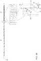
- FIG. 1is a schematic illustration of a surgical procedure, in accordance with some embodiments of the present invention.
- FIGS. 2A-Bare schematic illustrations of the outer tube of a guidewire, in accordance with some embodiments of the present invention.
- a plurality of slitsare formed in the outer tube of the guidewire during the manufacture thereof.
- a challengeis that when the guidewire bends, the bending stress imparted to the remaining uncut portions of the outer tube may cause these uncut portions to crack, due to poor distribution of the stress.
- embodiments of the present inventionprovide the slits with one or more stress-distributing features, such that the bending stress applied to the guidewire does not cause the outer tube of the guidewire to crack.
- the ends of the slitsmay be angled obliquely with respect to the longitudinal axis of the guidewire, and/or each of at least some of the slit-ends may widen toward the termination of the slit-end.
- the number of bendable uncut portions of the outer tubemay be increased, by nesting the distal end of each slit between the respective proximal ends of two other slits.
- a variableis said to “approximately” attain a particular value if the variable is within ⁇ 10% of that value.
- FIG. 1is a schematic illustration of a surgical procedure, in accordance with some embodiments of the present invention.
- FIG. 1depicts a procedure for removal of a clot from a blood vessel, such as a cranial blood vessel, of a subject 22 .
- a physician 20inserts a guidewire 24 into the body of subject 22 , e.g., via an artery in a thigh of the subject.
- physician 20navigates the guidewire to the target site at which the clot is located, using a guidewire torquer 26 coupled to the proximal end of guidewire 24 .
- the target sitemay be displayed on a display 27 .
- the physiciandelivers one or more tools over the guidewire, and then uses the tools to perform surgery at the site.
- the physicianmay deliver a microcatheter over the guidewire, after which the guidewire may be withdrawn.
- the physicianmay insert a stent retriever through the microcatheter, and advance both the microcatheter and the stent retriever into the clot.
- the physicianmay withdraw the microcatheter such that the stent retriever expands within the clot, thus opening the blood vessel.
- Guidewire 24comprises an outer tube, which facilitates the navigation of the guidewire by distally transferring the torque applied to the guidewire by the physician.
- the outer tube of the guidewirecomprises a plurality of bendable strips, which, by bending, facilitate flexion of the outer tube.
- the bendable stripsare configured to distribute the bending stress applied to the outer tube such that the bending stress at any one particular point does not exceed the threshold bending stress at which the outer tube would crack.
- the outer tubemay bend (or “flex”) even at sharp angles.
- the bend radius of the outer tubei.e., the minimum radius at which the outer tube can bend without cracking (or undergoing any other type of damage)—may be relatively small, e.g., equal to or less than half the outer diameter of the tube.
- the guidewiremay be navigated even to regions of the brain that are generally hard to reach, such as the M2 region of the middle cerebral artery.
- the guidewiremay comprise any other suitable components, which may be disposed, for example, within the outer tube.
- suitable componentsinclude a coil for reinforcing the outer tube, sensors (e.g., electromagnetic sensors) for use with a position-tracking system, fiber-optical components, and/or wires for carrying electrical signals. These components may be inserted into the outer tube during the manufacture of the guidewire.
- guidewire 24may be used in any suitable procedure.
- the guidewiremay be inserted into any appropriate portion of a body, such as a paranasal sinus, a vena cava, or another blood vessel.
- any suitable medical devicemay be guided over the guidewire.
- FIGS. 2A-Bare schematic illustrations of the outer tube 29 of guidewire 24 , in accordance with some embodiments of the present invention.
- FIG. 2Aexpands part of the proximal portion 36 of outer tube 29
- FIG. 2Bexpands part of the distal portion 38 of the outer tube.
- Outer tube 29comprises a cylindrical wall 25 surrounding a lumen, within which other components of the guidewire (e.g., a reinforcing coil) may be disposed, as described above with reference to FIG. 1 .
- Wall 25may be made of any suitable material, such as a metal (e.g., Nitinol, stainless steel, or titanium) or a polymer.
- the thickness of wall 25is between 25 and 150 microns.
- the length of the tubeis between 150 and 400 cm, and/or the outer diameter of the tube is between 0.012′′ and 0.04′′.
- Outer tube 29is shaped to define a plurality of slits (or “cuts”) 32 ; in other words, slits 32 are formed in wall 25 of the tube.
- the tubecomprises a plurality of bendable strips 28 ; more specifically, as further described below, bendable strips 28 are disposed between the ends of slits 32 .
- the width w 0 of each of the bendable stripsis relatively small (e.g., between 0.025 and 0.1 mm), such that the bendable strips bend in response to an applied torque. (It is noted that the width of each strip is not necessarily constant along the length of the strip.)
- Slits 32may be formed using any suitable technique, such as laser cutting, electric discharge machining, conventional machining (e.g., milling and/or lathing), or chemical etching.
- the density of the slitsi.e., the number of slits per unit length of the tube
- the flexibility of the tubeincreases moving distally along the tube.
- the tubemay comprise two portions: proximal portion 36 , along which the density of the slits has a first, lower value, and distal portion 38 , along which the density has a second, higher value.
- the tubemay further comprise one or more middle portions, which have respective intermediate slit-density values and are disposed between proximal portion 36 and distal portion 38 .
- the density of the slitsmay gradually increase (moving distally) over the length of the tube, such that the density attains a continuum of values, e.g., 10 or more discrete values.
- the distal end of the tube, and/or the proximal end of the tubeare not shaped to define any slits.
- w 0may be less at the distal portion of the tube than at the proximal portion of the tube. As a purely illustrative example, w 0 may be approximately 0.0025′′ at the proximal portion and approximately 0.0015′′ at the distal portion. For embodiments in which the tube comprises one or more middle portions, w 0 may attain any number of intermediate values between the proximal and distal portions of the tube.
- each slithas an oblique proximal end 34 and an oblique distal end 35 , in that the angle ⁇ between each of the slit-ends and longitudinal axis 30 is greater than zero and less than 90 degrees.
- ⁇may be between 5 and 85 degrees.
- angle ⁇may be greater at distal portion 38 than at proximal portion 36 .
- angle ⁇may be between 10 and 40 degrees at the proximal portion of the tube, and between 30 and 60 degrees at the distal portion of the tube.
- ⁇may attain any number of intermediate values between the proximal and distal portions of the tube.
- distal end 35 of each of the slits(except for the distalmost two slits) is situated (or “nested”) between the proximal end of a first other slit and the proximal end of a second other slit.
- one bendable stripis disposed between the distal end of the slit and the proximal end of the first other slit
- another bendable stripis disposed between the distal end of the slit and the proximal end of the second other slit.
- each of the slitsexcept for the proximalmost two slits, is nested between the respective distal ends of two other slits, such that two bendable strips are disposed proximally and distally, respectively, to the proximal end.
- FIG. 2Bshows a first slit 32 a having a distal end 35 a nested between (i) the proximal end 34 b of a first other slit 32 b , and (ii) the proximal end 34 c of a second other slit 32 c .
- the distal end 35 b of slit 32 bis nested between proximal end 34 c and the proximal end of yet another slit.
- a curve 40traces the path of slit 32 b , the dotted portion of curve 40 corresponding to the portion of the slit running along the far side of the tube.
- the bendable stripsare arranged helically along the tube, i.e., a hypothetical helical curve 42 ( FIG. 2A ) running along the tube passes through the bendable strips.
- a hypothetical helical curve 42FIG. 2A
- the tubedoes not have a preferential direction of flexion.
- the angular length of each slit(i.e., the angle along the circumference of the outer tube spanned by the slit) is between 200 and 480 degrees.
- the angular length of each slitmay be approximately 270 degrees.
- slits 32have respective middle portions 44 , middle portion 44 of each slit being perpendicular to longitudinal axis 30 and running from the proximal end of the slit to the distal end of the slit. In other embodiments, slits 32 do not have middle portions 44 ; rather, the slits are entirely oblique.
- the angular length ⁇ of each slit-endis between 20 and 240 degrees. Since ⁇ is typically the same for the proximal and distal slit-ends, ⁇ is typically ( ⁇ )/2, where (i) ⁇ is the angular length of the slit, and (ii) ⁇ is the angular length of middle portion 44 , or zero if the slit does not comprise a middle portion. ( ⁇ and ⁇ are not explicitly marked in FIGS. 2A-B .)
- ⁇may be less at the distal portion of the tube than at the proximal portion of the tube.
- ⁇may be 80-100 degrees at the proximal portion of the tube but only 50-70 degrees at the distal portion of the tube.
- ⁇may be 400-480 degrees at the proximal portion of the tube but only 180-320 degrees at the distal portion of the tube.
- ⁇may attain any number of intermediate values between the proximal and distal portions of the tube.
- the arc length s 0 of each bendable stripis between 0.3 and 0.9 times the outer diameter of the tube.
- s 0may be between 0.0036′′ and 0.036′′.
- s 0may be less at the distal portion of the tube than at the proximal portion of the tube, as described above for ⁇ .
- the tubecomprises a plurality of wider strips 46 , each wider strip 46 being disposed between a successive two of middle portions 44 .
- Wider strips 46are wider than the bendable strips and hence, typically, do not bend as much as do the bendable strips. Due to the greater density of the slits along distal portion 38 , the width w 1 of each wider strip may be less at the distal portion 38 than at proximal portion 36 .
- w 1may be approximately 0.007′′ at the proximal portion and approximately 0.002′′ at the distal portion.
- w 1may attain any number of intermediate values between the proximal and distal portions of the tube.
- the width w 3 of each slitis between 12 and 75 microns.
- width w 3is non-constant for at least some of the slit-ends.
- each slit-end of at least some of proximal ends 34 and some of distal ends 35may widen toward the termination of the slit-end, such that the termination of the slit-end is bulbous.
- the bulbous shape of the slit-endshelps to distribute the stress applied to the slit-ends.
- the variation in width w 3 along each slit-endis greater at the proximal portion of the tube, where the density of the slits is smaller, than at the distal portion of the tube.
- scope of the present inventionincludes the formation of slits and bendable portions as described herein in any tubular body, including, for example, a catheter or a plumbing snake.
Landscapes
- Health & Medical Sciences (AREA)
- Life Sciences & Earth Sciences (AREA)
- Animal Behavior & Ethology (AREA)
- Veterinary Medicine (AREA)
- Public Health (AREA)
- Engineering & Computer Science (AREA)
- Biomedical Technology (AREA)
- Heart & Thoracic Surgery (AREA)
- General Health & Medical Sciences (AREA)
- Anesthesiology (AREA)
- Hematology (AREA)
- Pulmonology (AREA)
- Biophysics (AREA)
- Surgery (AREA)
- Orthopedic Medicine & Surgery (AREA)
- Vascular Medicine (AREA)
- Nuclear Medicine, Radiotherapy & Molecular Imaging (AREA)
- Medical Informatics (AREA)
- Molecular Biology (AREA)
- Media Introduction/Drainage Providing Device (AREA)
Abstract
Description
Claims (20)
Priority Applications (5)
| Application Number | Priority Date | Filing Date | Title |
|---|---|---|---|
| US16/584,577US11478609B2 (en) | 2019-09-26 | 2019-09-26 | Bendable guidewire |
| JP2020160680AJP7593548B2 (en) | 2019-09-26 | 2020-09-25 | Bendable Guidewire |
| KR1020200124953AKR20210037589A (en) | 2019-09-26 | 2020-09-25 | Bendable guidewire |
| CN202011024802.8ACN112546402B (en) | 2019-09-26 | 2020-09-25 | Bendable guide wire |
| EP20198362.4AEP3799917B1 (en) | 2019-09-26 | 2020-09-25 | Bendable guidewire |
Applications Claiming Priority (1)
| Application Number | Priority Date | Filing Date | Title |
|---|---|---|---|
| US16/584,577US11478609B2 (en) | 2019-09-26 | 2019-09-26 | Bendable guidewire |
Publications (2)
| Publication Number | Publication Date |
|---|---|
| US20210093832A1 US20210093832A1 (en) | 2021-04-01 |
| US11478609B2true US11478609B2 (en) | 2022-10-25 |
Family
ID=72659617
Family Applications (1)
| Application Number | Title | Priority Date | Filing Date |
|---|---|---|---|
| US16/584,577Active2040-06-09US11478609B2 (en) | 2019-09-26 | 2019-09-26 | Bendable guidewire |
Country Status (5)
| Country | Link |
|---|---|
| US (1) | US11478609B2 (en) |
| EP (1) | EP3799917B1 (en) |
| JP (1) | JP7593548B2 (en) |
| KR (1) | KR20210037589A (en) |
| CN (1) | CN112546402B (en) |
Families Citing this family (6)
| Publication number | Priority date | Publication date | Assignee | Title |
|---|---|---|---|---|
| JP7169391B2 (en) | 2021-03-26 | 2022-11-10 | 株式会社リブドゥコーポレーション | folded absorbent article |
| WO2023081428A1 (en)* | 2021-11-05 | 2023-05-11 | Kai Medtech Llc | Laser cut hypotube patterns |
| US20230148846A1 (en)* | 2021-11-17 | 2023-05-18 | Greene Group Industries, Llc | Single Piece Stamped Flexure |
| JP2025510903A (en)* | 2022-03-30 | 2025-04-15 | オーバスネイチ・メディカル・プライベート・リミテッド | Multifilament Catheter Body Structure |
| WO2024226927A1 (en)* | 2023-04-28 | 2024-10-31 | Covidien Lp | Guidewire including an elongated body with a flexible distal section |
| WO2024226913A1 (en)* | 2023-04-28 | 2024-10-31 | Covidien Lp | Guidewire including an elongated body with a flexible distal section |
Citations (16)
| Publication number | Priority date | Publication date | Assignee | Title |
|---|---|---|---|---|
| JPH08257128A (en) | 1995-03-24 | 1996-10-08 | Piolax Inc | Medical tube |
| US5957903A (en) | 1991-10-15 | 1999-09-28 | Advanced Cardiovascular Systems, Inc. | Variable stiffness guidewire |
| WO2004047899A1 (en) | 2002-11-25 | 2004-06-10 | Invatec S.R.L. | Pipe having at least a portion with a variable flexibility |
| US20050027287A1 (en) | 1999-03-24 | 2005-02-03 | O'connor Michael J. | Variable stiffness heating catheter |
| US20060100687A1 (en) | 2004-11-10 | 2006-05-11 | Creganna Technologies Limited | Elongate tubular member for use in medical device shafts |
| US20070135763A1 (en)* | 2005-12-12 | 2007-06-14 | Musbach Frank A | Micromachined medical devices |
| US7708704B2 (en) | 2006-07-31 | 2010-05-04 | Codman & Shurtleff, Pc | Interventional medical device component having an interrupted spiral section and method of making the same |
| US20110130648A1 (en) | 2009-11-30 | 2011-06-02 | Christopher Thomas Beeckler | Catheter with pressure measuring tip |
| WO2012158152A1 (en) | 2011-05-13 | 2012-11-22 | Spiration, Inc. | Deployment catheter |
| US20160100745A1 (en)* | 2014-02-18 | 2016-04-14 | Olympus Corporation | Bending tube for endoscope and endoscope |
| US20160287054A1 (en) | 2014-04-08 | 2016-10-06 | Olympus Corporation | Endoscope |
| US20170189104A9 (en) | 2008-06-06 | 2017-07-06 | Biosense Webster, Inc. | Catheter with bendable tip |
| WO2017191636A1 (en) | 2016-05-04 | 2017-11-09 | Accurate Medical Therapeutics Ltd. | Embolization microcatheter head having slitted pattern |
| US20180015254A1 (en)* | 2016-07-13 | 2018-01-18 | NeuVT Limited | High flexibility, kink resistant catheter shaft |
| US20180067824A1 (en) | 2016-09-08 | 2018-03-08 | International Business Machines Corporation | Using run time and historical customer profiling and analytics to determine customer disaster recovery vs. production differences, and to enhance customer disaster recovery readiness and effectiveness |
| US20180093070A1 (en)* | 2016-10-05 | 2018-04-05 | Orbusneich Medical, Inc. | Modular Vascular Catheter |
Family Cites Families (23)
| Publication number | Priority date | Publication date | Assignee | Title |
|---|---|---|---|---|
| US20030069522A1 (en)* | 1995-12-07 | 2003-04-10 | Jacobsen Stephen J. | Slotted medical device |
| US6004279A (en)* | 1996-01-16 | 1999-12-21 | Boston Scientific Corporation | Medical guidewire |
| US6246914B1 (en)* | 1999-08-12 | 2001-06-12 | Irvine Biomedical, Inc. | High torque catheter and methods thereof |
| US9339632B2 (en)* | 2006-09-27 | 2016-05-17 | Boston Scientific Scimed, Inc. | Catheter shaft designs |
| US8556914B2 (en)* | 2006-12-15 | 2013-10-15 | Boston Scientific Scimed, Inc. | Medical device including structure for crossing an occlusion in a vessel |
| US20110160680A1 (en)* | 2009-12-29 | 2011-06-30 | Cook Incorporated | Wire guide with cannula |
| JP5399301B2 (en)* | 2010-03-12 | 2014-01-29 | テルモ株式会社 | catheter |
| EP2844135B1 (en) | 2012-05-03 | 2022-06-29 | St. Jude Medical Coordination Center BVBA | Tube and sensor guide wire comprising tube |
| JP2014147458A (en)* | 2013-01-31 | 2014-08-21 | Asahi Intecc Co Ltd | Slit pipe and guide wire with the same |
| CN103961785A (en)* | 2013-01-31 | 2014-08-06 | 朝日英达科株式会社 | Slitted pipe and guide wire using the same |
| JP2014147459A (en)* | 2013-01-31 | 2014-08-21 | Asahi Intecc Co Ltd | Slit pipe and guide wire with the same |
| CN105209102B (en)* | 2013-03-15 | 2018-10-02 | 波士顿科学国际有限公司 | Pressure-sensing seal wire |
| EP2990071B1 (en)* | 2013-04-26 | 2020-01-22 | Terumo Kabushiki Kaisha | Medical elongated body |
| US10363398B2 (en)* | 2014-10-06 | 2019-07-30 | Sanovas Intellectual Property, Llc | Steerable catheter with flexing tip member |
| US10820923B2 (en)* | 2016-05-16 | 2020-11-03 | Biosense Webster (Israel) Ltd. | Insertion tube with deflectable tip |
| US20200077991A1 (en)* | 2016-05-31 | 2020-03-12 | Intuitive Surgical Operations, Inc. | Pliant biopsy needle system |
| WO2018006041A1 (en)* | 2016-06-30 | 2018-01-04 | Avinger, Inc. | Atherectomy catheter with shapeable distal tip |
| US11207502B2 (en)* | 2016-07-18 | 2021-12-28 | Scientia Vascular, Llc | Guidewire devices having shapeable tips and bypass cuts |
| JP6917372B2 (en)* | 2016-07-20 | 2021-08-11 | テルモ株式会社 | Medical long body |
| US11330964B2 (en)* | 2016-10-03 | 2022-05-17 | Fortimedix Assets Ii B.V. | Bendable tube with improved elastic hinge |
| US10994102B2 (en)* | 2017-02-10 | 2021-05-04 | Corindus, Inc. | Method and apparatus for loading a guidewire into a connector with a valve |
| JP6937151B2 (en) | 2017-03-31 | 2021-09-22 | 川澄化学工業株式会社 | Medical tubular members, foreign body removal devices and foreign body removal catheters |
| US11167095B2 (en)* | 2018-03-08 | 2021-11-09 | Spiration, Inc. | Variable pitch flexible needle |
- 2019
- 2019-09-26USUS16/584,577patent/US11478609B2/enactiveActive
- 2020
- 2020-09-25JPJP2020160680Apatent/JP7593548B2/enactiveActive
- 2020-09-25CNCN202011024802.8Apatent/CN112546402B/enactiveActive
- 2020-09-25KRKR1020200124953Apatent/KR20210037589A/enactivePending
- 2020-09-25EPEP20198362.4Apatent/EP3799917B1/enactiveActive
Patent Citations (20)
| Publication number | Priority date | Publication date | Assignee | Title |
|---|---|---|---|---|
| US5957903A (en) | 1991-10-15 | 1999-09-28 | Advanced Cardiovascular Systems, Inc. | Variable stiffness guidewire |
| JPH08257128A (en) | 1995-03-24 | 1996-10-08 | Piolax Inc | Medical tube |
| US20050027287A1 (en) | 1999-03-24 | 2005-02-03 | O'connor Michael J. | Variable stiffness heating catheter |
| WO2004047899A1 (en) | 2002-11-25 | 2004-06-10 | Invatec S.R.L. | Pipe having at least a portion with a variable flexibility |
| US20060100571A1 (en) | 2002-11-25 | 2006-05-11 | Andrea Venturelli | Pipe having at least a portion with a variable flexibility |
| US20060100687A1 (en) | 2004-11-10 | 2006-05-11 | Creganna Technologies Limited | Elongate tubular member for use in medical device shafts |
| EP1656963A1 (en) | 2004-11-10 | 2006-05-17 | Creganna Technologies Limited | Elongate tubular member for use in medical device shafts |
| US20070135763A1 (en)* | 2005-12-12 | 2007-06-14 | Musbach Frank A | Micromachined medical devices |
| US7708704B2 (en) | 2006-07-31 | 2010-05-04 | Codman & Shurtleff, Pc | Interventional medical device component having an interrupted spiral section and method of making the same |
| US20170189104A9 (en) | 2008-06-06 | 2017-07-06 | Biosense Webster, Inc. | Catheter with bendable tip |
| US20110130648A1 (en) | 2009-11-30 | 2011-06-02 | Christopher Thomas Beeckler | Catheter with pressure measuring tip |
| WO2012158152A1 (en) | 2011-05-13 | 2012-11-22 | Spiration, Inc. | Deployment catheter |
| US20160100745A1 (en)* | 2014-02-18 | 2016-04-14 | Olympus Corporation | Bending tube for endoscope and endoscope |
| US20160287054A1 (en) | 2014-04-08 | 2016-10-06 | Olympus Corporation | Endoscope |
| WO2017191636A1 (en) | 2016-05-04 | 2017-11-09 | Accurate Medical Therapeutics Ltd. | Embolization microcatheter head having slitted pattern |
| US20190217052A1 (en) | 2016-05-04 | 2019-07-18 | Accurate Medical Therapeutics Ltd. | Embolization microcatheter head having slitted pattern |
| US20180015254A1 (en)* | 2016-07-13 | 2018-01-18 | NeuVT Limited | High flexibility, kink resistant catheter shaft |
| US20180067824A1 (en) | 2016-09-08 | 2018-03-08 | International Business Machines Corporation | Using run time and historical customer profiling and analytics to determine customer disaster recovery vs. production differences, and to enhance customer disaster recovery readiness and effectiveness |
| US20180093070A1 (en)* | 2016-10-05 | 2018-04-05 | Orbusneich Medical, Inc. | Modular Vascular Catheter |
| WO2018067824A1 (en) | 2016-10-05 | 2018-04-12 | Orbusneich Medical, Inc. | Modular vascular catheter |
Non-Patent Citations (1)
| Title |
|---|
| EP 20198624-1132—Extended European Search Report dated Mar. 9, 2021. |
Also Published As
| Publication number | Publication date |
|---|---|
| JP2021053386A (en) | 2021-04-08 |
| US20210093832A1 (en) | 2021-04-01 |
| EP3799917A1 (en) | 2021-04-07 |
| EP3799917B1 (en) | 2023-02-15 |
| CN112546402A (en) | 2021-03-26 |
| JP7593548B2 (en) | 2024-12-03 |
| KR20210037589A (en) | 2021-04-06 |
| CN112546402B (en) | 2024-07-05 |
Similar Documents
| Publication | Publication Date | Title |
|---|---|---|
| US11478609B2 (en) | Bendable guidewire | |
| CN109789292B (en) | Modular vascular catheter | |
| CN108430563B (en) | Flexible conduit | |
| JP2023166626A (en) | Vascular re-entry catheter | |
| EP2687255B1 (en) | Guidewire with highly flexible tip | |
| US8182432B2 (en) | Corewire design and construction for medical devices | |
| AU2010208618B2 (en) | Guidewire | |
| US10953197B2 (en) | Guide extension catheter | |
| EP0778040A2 (en) | Hollow guide wire apparatus for catheters | |
| CN115916314A (en) | Preformed Medical Devices | |
| WO2006135853A2 (en) | Devices, systems and methods useable for treating sinusitis | |
| CN111686360A (en) | Carotid artery nerve and blood vessel catheter | |
| CN102202717B (en) | Navigation guideline capable of navigating through anatomy with branches | |
| CN114901202A (en) | Vascular reentry catheter | |
| US20110202038A1 (en) | Guidewire positioning device | |
| US20230144490A1 (en) | Laser cut hypotube patterns | |
| US20240358969A1 (en) | Catheter including an elongated body with interconnecting struts | |
| US20230310798A1 (en) | Multi-filar catheter body construction | |
| JP2025523232A (en) | Coronary or Vascular Wires | |
| HK40100454B (en) | Multi-filar catheter body construction | |
| HK1255639B (en) | Flexible catheter |
Legal Events
| Date | Code | Title | Description |
|---|---|---|---|
| FEPP | Fee payment procedure | Free format text:ENTITY STATUS SET TO UNDISCOUNTED (ORIGINAL EVENT CODE: BIG.); ENTITY STATUS OF PATENT OWNER: LARGE ENTITY | |
| AS | Assignment | Owner name:BIOSENSE WEBSTER (ISRAEL) LTD., ISRAEL Free format text:ASSIGNMENT OF ASSIGNORS INTEREST;ASSIGNORS:BEECKLER, CHRISTOPHER THOMAS;KEYES, JOSEPH THOMAS;SIGNING DATES FROM 20191028 TO 20200128;REEL/FRAME:051867/0748 | |
| STPP | Information on status: patent application and granting procedure in general | Free format text:DOCKETED NEW CASE - READY FOR EXAMINATION | |
| STPP | Information on status: patent application and granting procedure in general | Free format text:NON FINAL ACTION MAILED | |
| STPP | Information on status: patent application and granting procedure in general | Free format text:RESPONSE TO NON-FINAL OFFICE ACTION ENTERED AND FORWARDED TO EXAMINER | |
| STPP | Information on status: patent application and granting procedure in general | Free format text:FINAL REJECTION MAILED | |
| STPP | Information on status: patent application and granting procedure in general | Free format text:RESPONSE AFTER FINAL ACTION FORWARDED TO EXAMINER | |
| STPP | Information on status: patent application and granting procedure in general | Free format text:ADVISORY ACTION MAILED | |
| STPP | Information on status: patent application and granting procedure in general | Free format text:DOCKETED NEW CASE - READY FOR EXAMINATION | |
| STPP | Information on status: patent application and granting procedure in general | Free format text:NOTICE OF ALLOWANCE MAILED -- APPLICATION RECEIVED IN OFFICE OF PUBLICATIONS | |
| STPP | Information on status: patent application and granting procedure in general | Free format text:PUBLICATIONS -- ISSUE FEE PAYMENT VERIFIED | |
| STCF | Information on status: patent grant | Free format text:PATENTED CASE |