US11478597B2 - Nasal assembly - Google Patents
Nasal assemblyDownload PDFInfo
- Publication number
- US11478597B2 US11478597B2US17/537,557US202117537557AUS11478597B2US 11478597 B2US11478597 B2US 11478597B2US 202117537557 AUS202117537557 AUS 202117537557AUS 11478597 B2US11478597 B2US 11478597B2
- Authority
- US
- United States
- Prior art keywords
- cushion
- holes
- frame
- columns
- vent
- Prior art date
- Legal status (The legal status is an assumption and is not a legal conclusion. Google has not performed a legal analysis and makes no representation as to the accuracy of the status listed.)
- Active
Links
Images


Classifications
- A—HUMAN NECESSITIES
- A61—MEDICAL OR VETERINARY SCIENCE; HYGIENE
- A61M—DEVICES FOR INTRODUCING MEDIA INTO, OR ONTO, THE BODY; DEVICES FOR TRANSDUCING BODY MEDIA OR FOR TAKING MEDIA FROM THE BODY; DEVICES FOR PRODUCING OR ENDING SLEEP OR STUPOR
- A61M16/00—Devices for influencing the respiratory system of patients by gas treatment, e.g. ventilators; Tracheal tubes
- A61M16/06—Respiratory or anaesthetic masks
- A61M16/0683—Holding devices therefor
- A—HUMAN NECESSITIES
- A61—MEDICAL OR VETERINARY SCIENCE; HYGIENE
- A61M—DEVICES FOR INTRODUCING MEDIA INTO, OR ONTO, THE BODY; DEVICES FOR TRANSDUCING BODY MEDIA OR FOR TAKING MEDIA FROM THE BODY; DEVICES FOR PRODUCING OR ENDING SLEEP OR STUPOR
- A61M16/00—Devices for influencing the respiratory system of patients by gas treatment, e.g. ventilators; Tracheal tubes
- A61M16/06—Respiratory or anaesthetic masks
- A61M16/0605—Means for improving the adaptation of the mask to the patient
- A61M16/0633—Means for improving the adaptation of the mask to the patient with forehead support
- A—HUMAN NECESSITIES
- A61—MEDICAL OR VETERINARY SCIENCE; HYGIENE
- A61M—DEVICES FOR INTRODUCING MEDIA INTO, OR ONTO, THE BODY; DEVICES FOR TRANSDUCING BODY MEDIA OR FOR TAKING MEDIA FROM THE BODY; DEVICES FOR PRODUCING OR ENDING SLEEP OR STUPOR
- A61M16/00—Devices for influencing the respiratory system of patients by gas treatment, e.g. ventilators; Tracheal tubes
- A61M16/06—Respiratory or anaesthetic masks
- A61M16/0666—Nasal cannulas or tubing
- A—HUMAN NECESSITIES
- A61—MEDICAL OR VETERINARY SCIENCE; HYGIENE
- A61M—DEVICES FOR INTRODUCING MEDIA INTO, OR ONTO, THE BODY; DEVICES FOR TRANSDUCING BODY MEDIA OR FOR TAKING MEDIA FROM THE BODY; DEVICES FOR PRODUCING OR ENDING SLEEP OR STUPOR
- A61M16/00—Devices for influencing the respiratory system of patients by gas treatment, e.g. ventilators; Tracheal tubes
- A61M16/08—Bellows; Connecting tubes ; Water traps; Patient circuits
- A61M16/0816—Joints or connectors
- A61M16/0825—Joints or connectors with ball-sockets
Definitions
- the present inventionrelates to a nasal assembly used for treatment, e.g., of Sleep Disordered Breathing (SDB) with Continuous Positive Airway Pressure (CPAP) or Non-invasive Positive Pressure Ventilation (NPPV).
- SDBSleep Disordered Breathing
- CPAPContinuous Positive Airway Pressure
- NPPVNon-invasive Positive Pressure Ventilation
- Some nasal assemblies used in the treatment of SDBare designed for insertion into or adjacent the nasal passages of the patient. Air or other breathable gas is supplied by a blower and passed along a flexible conduit to the nasal assembly.
- the nasal assemblygenerally includes a relatively rigid shell, e.g., a frame, and a pair of nozzles (which may be in the form of nasal pillows, nasal prongs, cannula, or nasal puffs) that are mounted on the rigid shell and structured to be inserted into or adjacent the nasal passages of the patient.
- the nozzlesare usually held in place using a headgear assembly, the relatively rigid shell and headgear assembly being joined using some form of connector.
- Trimblediscloses a nasal puff assembly 20 that includes a nasal puff 22 adapted to be worn adjacent the nose of a patient, together with a harness assembly 24 adapted to be worn over the head of the patient.
- the harness assembly 24is designed to operatively hold puff 22 adjacent and partially within the nasal passages of the patient.
- the puff 22is in the form of a generally Y-shaped rigid hollow plenum chamber 28 together with a pair of laterally spaced apart nares elements 30. Adjustability of the nares elements 30 may be provided by rotatably mounting the elements 30 to the plenum chamber 28 and mounting the elements 30 in slots permitting selective lateral positioning of the elements 30 with respect to each other. Also, the harness assembly 24 may be adjusted to adjust the fit and seal of the nares elements 30 during use. That is, the force required to maintain a sufficient seal is directly associated with the force required to maintain a desired fit. Thus, adjustment of the fit or stability of the nasal assembly directly affects the seal, which can adversely affect patient comfort.
- nasal pillows or cannula mounted to rigid shellsare disclosed in U.S. Pat. Nos. 5,724,965 and 6,431,172.
- a nasal mask assembly manufactured by Viasysi.e., Spiritus
- a harness assemblyis engaged with the plenum chamber to adjust the fit and seal of the nares elements during use. Similar to Trimble, adjustment of the fit or stability of the nasal assembly directly affects the seal, which can adversely affect patient comfort.
- a nasal mask assembly manufactured by InnoMedi.e., Nasal Aire
- InnoMedi.e., Nasal Aire
- the nares elementsare structured to engage within the mucosal surfaces or internal passages of the patient's nose to maintain the nasal mask assembly on the patient's face and to provide a seal. See, e.g., U.S. Pat. No. 5,533,506.
- a nasal mask assembly manufactured by Stevenson Industries(see U.S. Pat. No. 6,012,455), i.e., CPAP-Pro, includes a dental anchor, a platform, and air supply tubes having nasal pads, wherein the platform supports the air supply tubes.
- the dental anchoris sized to be engaged between the teeth in the patient's mouth so as to retain the assembly in place.
- PCT Application Publication No. WO 00/13751discloses a device that includes gas delivery elements positioned into engagement with the patient's nose by a mouthpiece fitted to the patient's teeth.
- the prongstend to irritate the patient's nose due to the tension applied by the headgear assembly that pulls the rigid shell and prongs towards the patient's nose.
- Another problemis achievement of a sealing fit with the patient's nasal passages without sacrificing patient comfort.
- Another problemis irritation of the inside of the patient's nostrils caused by contact with the prongs, e.g., an edge thereof.
- Another problemis irritation of the inside of the patient's nostrils caused by air jetting (air flow irritation) from the prongs.
- Another problemis adjustment of the nasal assemblies relative to the nose and/or head of the patient so as to accommodate various shapes and angles of patient's noses.
- Still another problemis the direct association between sealing and stability forces that can affect patient comfort.
- a further needhas developed to even further reduce the noise associated with the washout or venting of exhaled gases from the breathing chamber.
- One aspect of the inventionis directed towards a nasal assembly, in particular an improved cushion/frame/vent/clip assembly having an improved frame, cushion, vent and/or clip component.
- the assemblymay effectively reduce the noise associated with gas washout or venting of the patient.
- Another aspect of the inventionis to prevent the use of an old-style frame (which has no vent holes) with a cushion as described herein (which also has no holes).
- Another aspect of the inventionis directed towards a frame that is easy and inexpensive to manufacture.
- Another aspect of the inventionis directed to a frame with a vent channel and a plurality of vent holes, in which case it is not necessary to provide the cushion with such gas washout vent holes.
- the clipmay have ribs to improve strength/stiffness, and/or to allow ease of grip.
- the clipmay also have wings with compound curvature to help improve strength/stiffness.
- the assemblyincludes a frame having a main body and lateral sides, each lateral side including an integrally formed lateral connector; and a cushion including a pair of nozzles to communicate with nasal passages of a patient's nose in use, the cushion being coupled with the main body of the frame, wherein the frame includes a vent channel provided in the main body, the vent channel including a pair of side walls extending from the main body towards a base wall, said base wall including at least one vent hole.
- a nasal assemblyfor delivering breathable gas to a patient, comprising a frame having a main body and lateral sides, each lateral side including an integrally formed lateral connector; and a cushion including a pair of nozzles to communicate with nasal passages of a patient's nose in use, the cushion being coupled with the main body of the frame, wherein the frame includes a plurality of vent holes, said vent holes being provided in two or more rows arranged such that the vent holes are offset from one another.
- a nasal assemblyfor delivering breathable gas to a patient, comprising a frame having a main body and lateral sides, each lateral side including an integrally formed lateral connector; and a cushion including a pair of nozzles to communicate with nasal passages of a patient's nose in use, the cushion being coupled with the main body of the frame, wherein the frame includes longitudinal cushion channels to receive longitudinal edges of the cushion, at least one of said cushion channels including at least one cut out to receive a lug of the cushion upon assembly.
- a nasal assemblyfor delivering breathable gas to a patient, comprising a frame having a main body and lateral sides, each lateral side including an integrally formed lateral connector; and a cushion including a pair of nozzles to communicate with nasal passages of a patient's nose in use, the cushion being coupled with the main body of the frame, wherein the frame includes a circumferential cushion channel provided to each said lateral side of the frame, said frame including a cored portion generally aligned with each circumferential cushion channel, said cushion including a corner lug to interface with each said cored portion.
- a nasal assemblyfor delivering breathable gas to a patient, comprising a frame having a main body and lateral sides, each lateral side including an integrally formed lateral connector, the frame including at least one vent hole; a cushion including a pair of nozzles to communicate with nasal passages of a patient's nose in use, the cushion being coupled with the main body of the frame; and a clip to secure the cushion to the frame, wherein the clip includes a vent window generally aligned with the at least one vent hole.
- a patient interface for delivering breathable gas to a patientcomprising a frame; a cushion to communicate with a patient's airways in use, the cushion being coupled with the frame; and a vent portion including a plurality of vent holes, said vent holes being provided in two or more rows and the rows being arranged such that the vent holes are offset from one another.
- a full-face mask frameincluding a main body having a longitudinal axis and a vent assembly provided to the main body.
- the vent assemblyincludes a plurality of holes arranged in at least one column.
- the at least one columnis aligned with or parallel to the longitudinal axis.
- Yet another aspect of the inventionrelates to a mask frame including a main body and a side frame portion provided on each lateral side of the main body.
- a vent assemblyis provided to each side frame portion.
- Each vent assemblyincludes a plurality of holes arranged in a multi-column pattern and each column is vertically staggered with respect to one another.
- the nasal assemblyincludes a frame and a cushion including a pair of nozzles to communicate with nasal passages of a patient's nose in use.
- the cushionis coupled with the frame.
- the cushionincludes a size indicator, a series of position arrows, text, and/or a logo provided to one side of the cushion.
- the size indicator, series of position arrows, text, and/or logoare adapted to provide a visual cue to assist the patient in achieving correct alignment and orientation of the cushion and frame with respect to the patient in use.
- the nasal assemblyincludes a frame including a main body and a cushion including a pair of nozzles to communicate with nasal passages of a patient's nose in use.
- the cushionis coupled with the main body of the frame.
- the frameincludes a vent channel provided in the main body.
- the vent channelincludes a pair of side walls extending from the main body towards a base wall. Each of the side walls includes a variable wall thickness along its length.
- the nasal assemblyincludes a frame and a cushion coupled to the frame.
- the cushionincludes a pair of nozzles to communicate with nasal passages of a patient's nose in use.
- the frameincludes a vent channel that leads to at least one vent hole.
- the vent channelis adapted to buffer and/or separate higher velocity and more turbulent air flow into and around the frame from an entrance to the at least one vent hole.
- Yet another aspect of the inventionrelates to a mask frame including a main body including an aperture adapted to communicate with an elbow and a vent assembly provided to the main body.
- the vent assemblyincludes a plurality of holes arranged around the aperture.
- FIG. 1is a perspective view of a nasal assembly according to an embodiment of the present invention
- FIG. 2is an exploded view illustrating a portion of the nasal assembly shown in FIG. 1 ;
- FIG. 3is a perspective view of a frame according to an embodiment of the invention.
- FIG. 4is a reverse perspective view thereof
- FIG. 5is a front view thereof
- FIG. 6is a rear view thereof
- FIG. 7is a side view thereof
- FIG. 8is a top view thereof
- FIG. 9is a cross-sectional view along line 9 - 9 of FIG. 8 ;
- FIG. 10is a cross-sectional view along a longitudinal axis of the frame, through one of the rows of vent holes;
- FIG. 11is a perspective view of a cushion according to an embodiment of the present invention.
- FIG. 12is a front view thereof
- FIG. 13is a top view thereof
- FIG. 14is a rear view thereof
- FIG. 15is a bottom view thereof
- FIG. 16is a front view similar to the front view of FIG. 12 , but from slightly different orientation;
- FIG. 17is a cross-sectional view along line 17 - 17 in FIG. 16 ;
- FIG. 18is a left side view thereof
- FIG. 19is a right side view thereof.
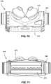
- FIG. 20is a perspective cross-sectional view along line 20 - 20 in FIG. 19 ;
- FIG. 21is a perspective view of a clip according to an embodiment of the present invention.
- FIG. 22is a reverse perspective view thereof
- FIG. 23is a front view thereof
- FIG. 24is a bottom view thereof
- FIG. 25is a rear view thereof
- FIG. 26is a side view thereof
- FIG. 27is a perspective view of a cushion subassembly according to an embodiment of the present invention.
- FIG. 28is a top view thereof
- FIG. 29is a bottom view thereof
- FIG. 30is a rear view thereof
- FIG. 31is a side view thereof
- FIG. 32is a front view thereof
- FIG. 33is a cross-sectional view along line 33 - 33 of FIG. 32 ;
- FIG. 34is a cross-sectional view along line 34 - 34 of FIG. 32 ;
- FIG. 35illustrates a vent assembly according to another embodiment of the present invention.
- FIGS. 36 and 37illustrate a vent assembly according to another embodiment of the present invention.
- FIGS. 38-44illustrate various views of a mask frame including a vent assembly according to another embodiment of the present invention.
- FIGS. 45-52illustrate various views of a mask frame including a vent assembly according to another embodiment of the present invention.
- FIGS. 53-55are various views of a cushion assembly according to another embodiment of the present invention.
- FIGS. 56A, 56B and 57are various views of a frame of the cushion assembly shown in FIGS. 53-55 ;
- FIGS. 58-59are cross-sectional views through line A-A of FIG. 57 ;
- FIGS. 60-61are cross-sectional views through line B-B of FIG. 57 ;
- FIGS. 62-64are various exploded views of the cushion assembly shown in FIGS. 53-55 ;
- FIG. 65is a side view illustrating correct orientation of the cushion assembly shown in FIGS. 53-55 on a patient;
- FIG. 66is a side view illustrating incorrect orientation of the cushion assembly shown in FIGS. 53-55 on a patient;
- FIG. 67is an exploded view of a nasal assembly according to another embodiment of the present invention.
- FIGS. 68-75are various views of a cushion assembly of the nasal assembly shown in FIG. 67 ;
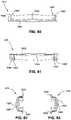
- FIGS. 76-83are various views of a clip of the nasal assembly shown in FIG. 67 ;
- FIG. 84illustrates a mask including a vent assembly according to another embodiment of the present invention.
- FIG. 85is a schematic view of the vent assembly shown in FIG. 84 ;
- FIGS. 86-87illustrate an elbow according to an embodiment of the present invention.
- FIG. 88illustrates an elbow retaining clip according to an embodiment of the present invention, the elbow retaining clip adapted for use with the elbow shown in FIGS. 86-87 .
- each illustrated embodimentincludes features that may be used with and/or in the other embodiments, or with the embodiments and/or components described in U.S. Non-Provisional application Ser. No. 10/781,929 and/or Ser. No. 11/101,657, as would be apparent to those of ordinary skill in the art.
- the general operation of the embodiments described hereinis substantially identical to the operation of the embodiments detailed in U.S. Ser. No. 10/781,929 and U.S. Ser. No. 11/101,557, and therefore will not be repeated.
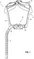
- FIG. 1illustrates a nasal assembly 5 according to an embodiment of the present invention.
- nasal assembly 5includes headgear 10 and a cushion assembly 15 .
- Headgear 10is designed to capture the crown of the patient's head. Adjustment of strap tension can be accomplished by pulling loose tabs 20 on the top of the head in opposite directions. The pulling direction is not aligned with the force the nozzle assembly applies to the patient. Therefore, the patient is more isolated from the strap adjustment forces.
- Yokes 25provide stability to the sides. Yokes 25 retain at least a partial portion of the basic shape of headgear, which facilitates donning of the headgear. Headgear need not include adjustability toward front of the face, as all adjustment of headgear can be effected at the back or top of the head.
- one end of the cushion assembly 15is provided with a plug 30 and the other end is provided with a swivel elbow 35 .
- the positions of the swivel elbow 35 and the plug 30may be interchanged, according to preference, e.g., the typical sleeping position of the patient.
- An air delivery tube 40is joined to the swivel elbow 35 .
- the air delivery tube 40may include a swivel connector and includes an end which also may be provided with a swivel connector. The end is provided with a source of pressurized gas.
- the elbow 35is angled about 120° from the cushion assembly 15 . This helps to keep the tube out of line of sight, to minimize pressure drop and to maintain the flexion point of tube as close to the face as possible.
- the elbowmay have a typical 90° bend.
- FIG. 2is an exploded view of a portion of the nasal assembly 5 shown in FIG. 1 , including the cushion assembly 15 , yoke 25 , seal portion 50 and elbow 35 (the other side of the cushion assembly is provided with a yoke, seal portion and an elbow or plug).
- the yoke 25may include a yoke ring 55 .
- the cushion assembly 15may be adjustably rotated with respect to headgear, to a position which best fits the patient.
- the ring of the yoke associated with the other side of the headgear(not shown) may include an alignment marker that can be selectively aligned with one of a plurality of alignment markers 60 provided on the cushion.
- Cushion assembly 15includes a frame 65 , a cushion 70 and a clip 75 .
- FIGS. 3-10show the frame in isolation
- FIGS. 11-20show the cushion in isolation
- FIGS. 21-26show the clip in isolation
- FIGS. 27-34show the assembly of the frame, cushion and clip.
- frame 65has a main body 80 and lateral sides. Each lateral side includes a lateral connector portion 85 .
- Frame 65is preferably made of molded plastic, e.g., polycarbonate and/or polypropylene.
- Main body 80 of frameis provided with a vent channel 90 defined by a base wall 92 and a pair of side walls 94 .
- Vent channel 90extends from an inside surface 95 of the main body toward the base wall 92 .
- An upper portion 100 of the vent channel 90is positioned in a plane just below the lowest point 110 of the inlet aperture 115 of lateral connector 85 .
- Each side wall 94converge towards one another in the direction of the base wall at a slight angle alpha ( ⁇ ), e.g., about 2-5 degrees, preferably 2 degrees.
- Each side wall 94has a lower portion 120 that is provided to the base wall 92 along a radius of curvature RL of about 0.2-0.4 mm, preferably about 0.3 mm, and the upper portion 100 that is curved, e.g., with a radius of curvature RU of between about 0.5 to 1.5 mm, preferably about 0.9 to 1.0 mm.
- the width WS between the side wallsis about 2-3 mm, preferably about 2.6 mm. The width between the side walls increases in the direction of upper portion 100 due to the angle alpha ( ⁇ ), described above.
- Channel 90is in communication with a plurality of vent holes 130 , e.g., 6-60 vent holes, and preferably about 35-45 vent holes, although there could be more than 60 holes or less than 6 holes, depending on application. In the example of FIG. 5 , there are 39 holes.
- Each vent hole 130has a generally part conic shape, including opposed walls 135 that converge from a larger diameter to a smaller diameter, as viewed in the direction of exhausted gas.
- the walls 135preferably converge at an angle beta ( ⁇ ), i.e., an included angle, of about 1-90 degrees, and preferably 2-8 degrees, and even more preferably about 5 degrees.
- Each wallpreferably has a radius of curvature HR of about 0.15-0.35 mm, preferably 0.25 mm.
- FIGS. 3, 5, 6 and 9illustrate one possible vent arrangement that includes offset rows of vent holes.
- FIG. 35illustrates a portion of a vent assembly 300 having a plurality of holes 305 , e.g., 5-10 holes or more, arranged in a pattern by three rows of holes 305 .
- the center rowincludes one or more additional holes at each end thereof.
- the positioning of the assembly 300is similar to that shown in FIG. 3 .
- FIG. 36illustrates a portion of a vent assembly 400 according to yet another embodiment of the invention.
- Vent assembly 400includes a plurality of vent holes 405 arranged in a predetermined pattern.
- FIG. 37is a plan view of the pattern which includes center rows 410 each including nine holes in side-by-side relation.
- Each center row 410is flanked by an intermediate row 415 , which in turn is flanked by outside rows 420 .
- Each intermediate row 415includes seven holes, while each outside row 420 includes three holes.
- the holes in outside rows 420are aligned with holes in the center rows 410 , while the holes in intermediate rows 415 are offset from both the center rows 410 and the outside rows 420 .
- any of the vent configurations described above, especially the embodiments described in relation to FIGS. 35-37could be incorporated into a nasal mask (e.g., ResMed's Mirage® nasal mask) or a full-face (nasal-oro) mask (e.g., ResMed's Ultra-Mirage® full face mask).
- a nasal maske.g., ResMed's Mirage® nasal mask
- a full-face (nasal-oro) maske.g., ResMed's Ultra-Mirage® full face mask
- vent holes in any of the above embodimentsmay be provided directly on the frame and/or the cushion.
- the frame, cushion and/or air delivery conduitcan be provided with an aperture into which a substrate with the holes is inserted or otherwise provided.
- the substratemay take the form of an insert, such as disclosed in U.S. Pat. No. 6,561,190, incorporated herein by reference in its entirety.
- vent holesmay be provided in headgear.
- the holes 130are preferably arranged in two rows having a predetermined pitch.
- the rowsare offset to allow more holes to be fitted into a smaller space, thereby keeping the size of the vent channel 90 to a minimum.
- the centers of holes in adjacent rowsare spaced a depth DH of about 0.75 to 1.25 mm, preferably 1.0 mm, and a width WH of about 1.1-1.3 mm, preferably about 1.175 mm.
- the center-to-center distance (“true pitch”) between the holesis about 1.5-1.6 mm, preferably about 1.54 mm.
- the length LVC of the vent channelis about 45-55 mm, preferably about 48 mm.
- Each hole 130preferably has the following dimensions: length HL: about 1.0-2.5 mm, preferably about 1.7 mm; outlet diameter HO: about 0.5-1.0 mm, preferably about 0.7 mm; radius of curvature at the upper end of the hole (HR): about 0.15-0.35 mm, preferably about 0.25 mm.
- Frame 65includes lugs 140 ( FIGS. 3, 4, 6, 8 and 10 ) to help form a longitudinal cushion channel 145 into which an edge portion 71 of the cushion 70 is fitted, to secure the cushion relative to the frame to form a frame/cushion subassembly prior to attachment of the clip.
- cushion channel 145is provided on each side of the vent channel.
- Cushion channel 145is provided with structure to enhance alignment with the cushion.
- each cushion channel 145may include one or more cut outs 150 to receive corresponding lugs 155 (e.g., FIG. 20 ) of the cushion (described below).
- Framealso includes circumferential channels 146 ( FIG. 5 ) to receive end portions 72 of the cushion 70 .
- Frameincludes cored portions 160 ( FIG. 10 ) adjacent to each lateral connector.
- Cored portions 160help facilitate manufacturing, by thinning out the plastic section.
- a thickened sectionhas a higher possibility of leaving sink marks.
- the vent channel 90 of the frame 65is structured to reduce vent noise generated by the vent holes.
- the entrance to the vent holes 130is located at the bottom of the vent channel 90 .
- turbulent inflowis entrained into or guided within the vent channel 90 which decreases the turbulence of the flow in the mask chamber before the flow passes into the vent holes 130 . Because the flow entering the vent is not highly turbulent, the noise induced by turbulent flow passing through the vent is reduced (effecting a noise reduction throughout the whole breathing cycle, not just inhalation).
- the vent channel 90also acts as a buffer between the high flow region (generally between the opposed inlet apertures 115 ) and the entrance to the vent holes 130 . This arrangement has the effect of quieting the nasal assembly during inhalation when flow through the nasal assembly is at its highest and most turbulent.
- inflow during inhalationincludes a relatively high velocity cross flow, wherein air enters the cushion assembly 15 laterally and normal to the orientation of the vent holes 130 .
- Noisemay be produced by this air flow if it encounters obstructions or irregularities, such as an array of vent holes.
- obstructions or irregularitiessuch as an array of vent holes.
- Cushion 70includes a main body 170 supporting a pair of nozzle members 175 that are designed to engage with a user's nares in use.
- cushionincludes one or more lugs 155 that are fitted snugly relative to cut 150 outs in frame 65 .
- the provision of the matching lugs and cut outshelps prevent the assembly of cushion 70 (that has no vent holes) to a frame (not shown) without a vent. Thus, the situation is avoided where the user inadvertently attempts to couple a ventless frame with a ventless cushion.
- Cushion 70has no vent holes, since the vent holes are provided in the frame 65 . However, the wall thickness of a portion 180 ( FIG. 19 ) of the cushion remains thickened to support nozzle members 175 .
- cushion 70includes corner lugs 185 to interface with cored portions 160 of frame 15 .
- Clip 75includes a main body having lateral ends, either one of which can be assembled to the cushion/frame subassembly, by sliding action to secure same.
- Clip 75includes a vent window 190 that aligns with the vent holes in vent channel upon assembly of the clip to the cushion/frame subassembly.
- Ribs 195help with strength and stiffness, as well as provide a grip surface.
- Wings 200preferably have a compound curved shape, to improve strength and stiffness.
- FIGS. 38-44illustrate an embodiment of a frame 550 for a full-face (nasal-oro) mask.
- the frame 550includes an upper support member 560 adapted to support a forehead support, lower headgear clip receptacles 570 adapted to be engaged with clips provided to straps of a headgear assembly, and a lower bore 580 adapted to engage an inlet conduit, e.g., elbow.
- the perimeter of the frameincludes a plurality of slots 590 therethrough, e.g., three slots. The slots 590 are adapted to engage a cushion clip that retains a cushion on the frame 550 .
- Such a frame arrangementis disclosed in PCT Application Nos. PCT/AU2006/000035 and PCT/AU2006/000037, each incorporated herein by reference in its entirety.
- the upper portion of the frame 550includes a vent assembly 500 similar to that shown in FIG. 35 .
- the vent assembly 500is positioned on the frame 550 below spaced-apart side walls 565 of the upper support member 560 .
- the vent assembly 500includes a plurality of holes 505 arranged in a three column pattern. As illustrated, the columns are aligned or parallel to the longitudinal axis L of the frame, e.g., the center column is aligned with the longitudinal axis and the outside columns are parallel to the longitudinal axis (see FIG. 41 ).
- the center column 510includes 10-20 holes, e.g., 15 holes, and each outside column 515 includes 8-15 holes, e.g., 12 holes.
- the holes 505 in the outside columns 515are aligned with the holes 505 in the center column 510 , with the center column 510 having one additional hole at the upper end and two additional holes at the lower end.
- each hole 505has a generally part conic shape, including opposed walls that converge from a larger (inside) diameter (e.g., about 1.28 mm) to a smaller (outside) diameter (e.g., about 0.7 mm), as viewed in the direction of exhausted gas.
- the included angle of the conemay be about 14°, the height of the cone may be about 2.38 mm, and a radius provided on the inside diameter may be about 0.75 mm.
- the frame 550may include other vent arrangements, e.g., the vent arrangement shown in FIGS. 36-37 .
- the first and second center columnsmay be parallel to and offset from the longitudinal axis of the frame.
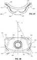
- FIGS. 45-52illustrate a vent configuration incorporated into a frame 650 for a nasal and mouth mask.
- the frame 650includes a main body 660 having a side frame portion 670 on each lateral side thereof.
- the main body 660includes an aperture 662 and a flanged collar member 664 adapted to engage an elbow.
- the frame 650includes a channel 680 for retaining a mouth cushion which supports nasal prongs.
- each side frame portion 670includes headgear attachment points, e.g., upper and lower anchors 672 , 674 , for attaching a headgear assembly.
- headgear attachment pointse.g., upper and lower anchors 672 , 674
- a vent assembly 600is provided in each side frame portion 670 of the frame 650 , adjacent the upper anchors 672 .
- Each vent assembly 600includes an array or pattern of relatively small holes 605 arranged in a plurality of columns, e.g., 3-10 columns, and in the example illustrated, 5 columns. The 5 columns are vertically staggered with respect to one another.
- the first hole in each columncooperate to form an axis A that is angled at an angle ⁇ (when viewed from the front as shown in FIG. 48 ) of about 15-35°, e.g., 25°, with respect to vertical axis V.
- each holeis provided along a plane P (approximate plane shown in FIG.
- each holehas a longitudinal axis L that is angled at an angle of about ⁇ 10° to about 45°, e.g., 0°, with respect to transverse axis T.
- Each columnincludes 2-6 holes, e.g., 4 holes.
- each hole 605has a generally part conic shape, including opposed walls that converge from a larger diameter to a smaller diameter, as viewed in the direction of exhausted gas.
- the smaller diametermay be about 0.7 mm
- the larger diametermay be about 1 mm
- the included angle of the conemay be about 10°
- the height of the conemay be about 1.7 mm.
- other vent arrangementsare possible.
- the holes 605are located away from the elbow aperture 662 to avoid air flow interference. Also, the holes 605 are located near headgear attachment points 672 where the frame 650 is relatively flat to the users face for the anchor structures. In addition, the holes 605 are positioned on relatively flat portions of the frame 650 so that air may be vented perpendicularly from the general plane of the patient's face to avoid air jetting towards a bed partner.
- this vent arrangementoptimizes mask operation and is synergistic in that it utilizes an area of the frame 650 which is relatively flat to the patient's face for two purposes, i.e., anchor structure and perpendicular venting. Aesthetics of the frame 650 are also improved significantly by reducing the number of relatively flat areas that are provided on the frame 650 .
- FIGS. 53-66illustrate a cushion assembly 715 according to another embodiment of the present invention.
- the cushion assembly 715includes a frame 765 and a cushion 770 provided to the frame 765 .
- a clipe.g., clip 75 described above, may be provided to secure the cushion 770 to the frame 765 .
- FIGS. 53-55show assembled views of the cushion 770 and frame 765
- FIGS. 56A-61show the frame 765 in isolation
- FIGS. 62-64show the assembly of the frame 765 and the cushion 770
- FIGS. 65-66illustrate orientation of the cushion assembly 715 .
- the frame 765has a main body 780 and lateral sides. Each lateral side includes a lateral connector portion 785 .
- the frame 765is preferably made of molded plastic, e.g., polycarbonate and/or polypropylene.
- the main body 780 of the frame 765is provided with a vent channel 790 defined by a base wall 792 and a pair of side walls 794 .
- the vent channel 790extends from an inside surface 795 of the main body toward the base wall 792 .
- the channel 790is in communication with a plurality of vent holes 830 , e.g., 6-60 vent holes, and preferably about 35-45 vent holes, although there could be more than 60 holes or less than 6 holes, depending on application. In the example of FIG. 57 , there are 38 holes.
- Each vent hole 830may have a similar conic shape such as vent hole 130 described above.
- the vent arrangementincludes offset rows of vent holes. However, other arrangements are possible.
- the frame 765includes lugs 840 to help form a longitudinal cushion channel 845 into which an edge portion 771 of the cushion 770 is fitted, to secure the cushion 770 relative to the frame 765 to form a frame/cushion subassembly prior to attachment of the clip.
- the cushion channel 845is provided on each side of the vent channel 790 and includes one or more cut outs 850 to receive corresponding lugs of the cushion 770 (as described above with respect to cushion 70 and frame 65 ).
- Frame 765also includes circumferential channels 846 to receive end portions of the cushion 770 .
- the side walls 794 of the frame 765are locally thickened at the cut outs 850 .
- the wall sections 51 at the cut outs 850i.e., between lugs 840
- This arrangementincreases the strength of the side wall 794 to reduce bending stress, which results in an increase in strength of the overall frame 765 .
- the wall section 51 between lugs 840 shown in FIGS. 58-59is thicker than the wall section S 2 supporting lugs 840 shown in FIGS. 60-61 .
- the wall section 51may have a thickness T of about 1.20 mm and the wall section S 2 may have a thickness t of about 1.0 mm.
- other thicknessesare possible depending on application.
- the side walls 794had a substantially constant wall thickness along its length.
- the radius R 1may be in the range of 0.1-0.95 mm, e.g., preferably 0.6 mm
- the radius R 2may be in the range of 0.1-0.95 mm, e.g., preferably 0.5 mm
- the radius R 3may be in the range of 0.1-1.2 mm, e.g., preferably 1.2 mm.
- the fillet size increaseprovides better stress distribution at the junction between the side walls 794 and the lugs 840 .
- the fillet size increase(along with the thickened side walls described above) results in overall strength improvement of the frame 765 .
- the cushion 770is substantially similar to the cushion 70 described above. As illustrated, the cushion 770 includes a main body 870 supporting a pair of nozzle members 875 that are designed to engage with a user's nares in use.
- the main body 870 of the cushion 770includes a size indicator 702 , e.g., medium (M) size, and a series of position arrows 704 to facilitate positioning between the headgear and the cushion assembly 715 .
- the cushion 770includes text and/or a logo 706 , e.g., ResMed logo. As illustrated, the logo 706 , the size indicator 702 , and the position arrows 704 protrude from the main body 870 , e.g., raised configuration, to facilitate recognition.
- the logo 706 , the size indicator 702 , and the position arrows 704are provided on one side of the main body 870 .
- This labeling arrangementprovides a visual cue to assist the patient in achieving correct alignment and orientation of the cushion 770 and frame 765 with respect to the patient.
- the labeling arrangementprevents incorrect assembly of the cushion assembly 715 (i.e., cushion 770 and frame 765 ) onto the headgear.
- the logo 706 , size indicator 702 , and position arrowsface outwards or away from the patient in use.
- the logo 706 , size indicator 702 , and position arrowsface inwards or towards the patient.
- the patientmay easily determine if the cushion assembly 715 is correctly oriented.
- the frame 765remains attached to the headgear and the cushion 770 is removed from the frame/headgear subassembly, e.g., for cleaning.
- the cushion 770is re-assembled to the frame 765 (e.g., see FIGS. 62-64 )
- the logo 706 , size indicator 702 , and position arrows 704may be used as a visual cue to assist the patient in achieving correct alignment and orientation of the cushion 770 onto the frame 765 .
- the logo 706 , the size indicator 702 , and/or the position arrows 704may be provided to facilitate orientation.
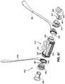
- FIGS. 67-83illustrate a nasal assembly 905 according to another embodiment of the present invention.
- the nasal assembly 905includes a cushion assembly 915 , yokes 925 to provide stability to the sides of the headgear, seal portion 950 and elbow 935 provided to one end of the cushion assembly 915 , and seal portion 950 and plug 930 provided to the other end of the cushion assembly 915 .
- the positions of the swivel elbow 935 and the plug 930may be interchanged, according to preference, e.g., the typical sleeping position of the patient.
- the yoke 925may include a yoke ring 955 .
- the cushion assembly 915may be adjustably rotated with respect to headgear, to a position which best fits the patient.
- the ring 955 of the yoke 925 associated with the other side of the headgearmay include one or more alignment markers 961 that can be selectively aligned with one of a plurality of alignment markers 960 provided on the cushion.
- the swivel elbow 935includes one end provided to the cushion assembly 915 and the opposite end provided to an air delivery tube. As illustrated, the end provided to the cushion assembly 915 includes two prongs 937 and a pair of key-shaped apertures 939 (only one aperture being visible) to reduce stress.
- Such a swivel elbowis disclosed in PCT Application No. PCT/AU2004/000207, filed Feb. 20, 2004, the entirety of which is incorporated herein by reference.
- the cushion assembly 915includes a frame 965 , a cushion 970 and a clip 975 .
- FIGS. 68-75show the assembly of the frame, cushion, and clip, and FIGS. 76-83 show the clip in isolation.
- the frame 965may be similar to one or more of the frames described above. Therefore, the frame 965 will not be described in further detail.
- the cushion 970may be similar to one or more of the cushions described above. Therefore, the cushion 970 will not be described in further detail.
- the clip 975includes a main body having lateral ends, either one of which can be assembled to the cushion/frame subassembly, by sliding action to secure the same.
- a clipis disclosed in U.S. Design application No. 29/258,084, filed Apr. 14, 2006, the entirety of which is incorporated herein by reference.
- the clip 975includes a vent window 1090 that aligns with the vent holes in vent channel upon assembly of the clip to the cushion/frame subassembly.
- the clip 975includes two ribs 1095 , 1097 provided on each lateral side thereof.
- the two ribs 1095 , 1097increases stiffness to prevent disassembly of the clip 975 , thus improving the retention and seal of the cushion 970 to the frame 965 .
- the two ribs 1095 , 1097improve usability by providing grip during assembly/disassembly.
- the clip 975includes wings 1000 on each side of the main body.
- the wings 1000extend laterally from a bottom of the clip 975 (e.g., in contrast to wings 200 that extend from a top surface of clip 75 .
- each wing 1000has a reinforced section 1002 that increases stiffness in the clamping direction to prevent disassembly of the clip 975 , thus improving the retention and seal of the cushion 970 to the frame 965 .
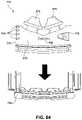
- FIG. 84illustrates a nasal and mouth mask 1115 including a frame 1150 having a vent assembly 1100 according to another embodiment of the present invention.
- the frame 1150is substantially similar to the frame 650 described above.
- the frame 1150includes a main body 1160 having a side frame portion 1170 on each lateral side thereof.
- the main body 1160includes an aperture 1162 (e.g., see FIG. 85 ) adapted to retain an elbow 1135 .
- the frame 1150is structured to retain a mouth cushion which supports nasal prongs 1175 .
- each side frame portion 1170includes headgear attachment points, e.g., upper and lower anchors 1172 , 1174 , for attaching a headgear assembly.
- the frame 1150includes a vent assembly 1100 that extends around the aperture 1162 and hence the elbow 1135 in use.
- the frame 1150includes a relatively flattened area 1151 around the aperture 1162 (also referred to as an elbow mounting hole) adapted to retain the elbow 1135 .
- the vent assembly 1100is provided to the relatively flattened area 1151 and includes an array or pattern of relatively small holes 1105 arranged in concentric circles around the aperture 1162 . This arrangement directs air directly away from all materials, e.g., pillows and bed linens, to reduce noise, and spreads the holes over a relatively wide area so that the bed partner will not be affected by a concentrated airstream.
- the holes 1105are arranged in two concentric circles C 1 , C 2 around the aperture 1162 .
- the holesmay be arranged in any number of circles around the aperture, e.g., 1-10 concentric circles.
- each circlemay include any suitable number of holes, e.g., 5-50 holes.
- the holes in adjacent circlesmay be aligned and/or offset from one another.
- the holes 1105may be arranged in other suitable arrangements around the aperture 1162 .
- the holes 1105may be non-concentrically arranged around the aperture 1162 , e.g., randomly arranged.
- each hole 1105may include a generally part conic shape as described above.
- vent assembly 1100may be incorporated into other mask arrangements, e.g., nasal mask, full-face mask, etc.
- the vent assembly 1100 described abovemay create noise when flow from the vent holes 1105 engages or blows into the back of the elbow 1135 .
- a “keyed” elbow retaining clipmay be used that is structured to mask holes when they are aligned with the elbow 1135 .
- FIGS. 86-88illustrate an elbow assembly according to an embodiment of the present invention.
- the elbow assemblyincludes an elbow 1135 ( FIGS. 86-87 ) and an elbow retaining clip 1136 ( FIG. 88 ) to retain the elbow 1135 to the frame 1150 .
- the elbow 1135includes a mating portion 1141 that is inserted into the aperture 1162 provided in the frame 1150 , and the elbow retaining clip 1136 is attached to the mating portion 1141 from an inner side of the frame 1150 so as to prevent withdrawal of the mating portion 1141 and hence the elbow 1135 from the aperture 1162 .
- the mating portion 1141includes a key or protrusion 1143 that is adapted to engage within a corresponding keyway or recess 1137 provided to the elbow retaining clip 1136 .
- the engagement between the key 1143 and keyway 1137ensures that the elbow retaining clip 1136 is correctly oriented with respect to the elbow 1135 .
- the elbow retaining clip 1136includes a wiper member or tab 1139 that is structured to block, cover, and/or mask one or more vent holes 1105 from the inner side of the frame 1150 which are aligned with the elbow 1135 .
- This arrangementblocks vent flow from blowing into the back of the elbow 1135 , which reduces noise in use. Because the elbow retaining clip 1136 is keyed with the elbow 1135 , the wiper member 1139 will rotate along the elbow 1135 to block the affected vent holes, i.e. vent holes aligned with the elbow 1135 .
- vent and elbow arrangementhas several advantages. For example, the relatively small vent holes provides lower mask noise for the patient and bed partner, and the diffuse placement of the vent holes provides a lower risk of the bed partner being affected. Because there are less complaints from the bed partner, the mask provides greater compliance as the patient may be more willing to wear the mask.
Landscapes
- Health & Medical Sciences (AREA)
- Pulmonology (AREA)
- Heart & Thoracic Surgery (AREA)
- Engineering & Computer Science (AREA)
- Anesthesiology (AREA)
- Biomedical Technology (AREA)
- Emergency Medicine (AREA)
- Hematology (AREA)
- Life Sciences & Earth Sciences (AREA)
- Animal Behavior & Ethology (AREA)
- General Health & Medical Sciences (AREA)
- Public Health (AREA)
- Veterinary Medicine (AREA)
- Otolaryngology (AREA)
- Respiratory Apparatuses And Protective Means (AREA)
Abstract
Description
Claims (29)
Priority Applications (2)
| Application Number | Priority Date | Filing Date | Title |
|---|---|---|---|
| US17/537,557US11478597B2 (en) | 2005-11-08 | 2021-11-30 | Nasal assembly |
| US17/966,569US11819619B2 (en) | 2005-11-08 | 2022-10-14 | Mask with vent columns |
Applications Claiming Priority (10)
| Application Number | Priority Date | Filing Date | Title |
|---|---|---|---|
| US73428205P | 2005-11-08 | 2005-11-08 | |
| US75820006P | 2006-01-12 | 2006-01-12 | |
| US29/258,084USD587800S1 (en) | 2006-04-14 | 2006-04-14 | Respiratory mask cushion frame |
| US79561506P | 2006-04-28 | 2006-04-28 | |
| US81962606P | 2006-07-11 | 2006-07-11 | |
| US83844206P | 2006-08-18 | 2006-08-18 | |
| PCT/AU2006/001507WO2007053878A1 (en) | 2005-11-08 | 2006-10-13 | Nasal assembly |
| US8437308A | 2008-04-30 | 2008-04-30 | |
| US15/293,694US11202877B2 (en) | 2005-11-08 | 2016-10-14 | Nasal assembly |
| US17/537,557US11478597B2 (en) | 2005-11-08 | 2021-11-30 | Nasal assembly |
Related Parent Applications (1)
| Application Number | Title | Priority Date | Filing Date |
|---|---|---|---|
| US15/293,694ContinuationUS11202877B2 (en) | 2005-11-08 | 2016-10-14 | Nasal assembly |
Related Child Applications (1)
| Application Number | Title | Priority Date | Filing Date |
|---|---|---|---|
| US17/966,569ContinuationUS11819619B2 (en) | 2005-11-08 | 2022-10-14 | Mask with vent columns |
Publications (2)
| Publication Number | Publication Date |
|---|---|
| US20220080148A1 US20220080148A1 (en) | 2022-03-17 |
| US11478597B2true US11478597B2 (en) | 2022-10-25 |
Family
ID=38022878
Family Applications (4)
| Application Number | Title | Priority Date | Filing Date |
|---|---|---|---|
| US12/084,373AbandonedUS20090151729A1 (en) | 2005-11-08 | 2006-10-13 | Nasal Assembly |
| US15/293,694Active2029-11-11US11202877B2 (en) | 2005-11-08 | 2016-10-14 | Nasal assembly |
| US17/537,557ActiveUS11478597B2 (en) | 2005-11-08 | 2021-11-30 | Nasal assembly |
| US17/966,569ActiveUS11819619B2 (en) | 2005-11-08 | 2022-10-14 | Mask with vent columns |
Family Applications Before (2)
| Application Number | Title | Priority Date | Filing Date |
|---|---|---|---|
| US12/084,373AbandonedUS20090151729A1 (en) | 2005-11-08 | 2006-10-13 | Nasal Assembly |
| US15/293,694Active2029-11-11US11202877B2 (en) | 2005-11-08 | 2016-10-14 | Nasal assembly |
Family Applications After (1)
| Application Number | Title | Priority Date | Filing Date |
|---|---|---|---|
| US17/966,569ActiveUS11819619B2 (en) | 2005-11-08 | 2022-10-14 | Mask with vent columns |
Country Status (2)
| Country | Link |
|---|---|
| US (4) | US20090151729A1 (en) |
| WO (1) | WO2007053878A1 (en) |
Cited By (1)
| Publication number | Priority date | Publication date | Assignee | Title |
|---|---|---|---|---|
| US12005189B2 (en) | 2013-10-03 | 2024-06-11 | ResMed Pty Ltd | Mask system having mask vent with recess and ribs |
Families Citing this family (121)
| Publication number | Priority date | Publication date | Assignee | Title |
|---|---|---|---|---|
| USD485905S1 (en)* | 2002-08-09 | 2004-01-27 | Resmed Limited | Nasal mask |
| JP4570966B2 (en) | 2002-09-06 | 2010-10-27 | レスメド・リミテッド | Cushion for breathing mask assembly |
| AU2003275762A1 (en) | 2002-11-06 | 2004-06-07 | Resmed Limited | Mask and components thereof |
| WO2004052438A1 (en) | 2002-12-06 | 2004-06-24 | Fisher & Paykel Healthcare Limited | Mouthpiece |
| US7588033B2 (en) | 2003-06-18 | 2009-09-15 | Breathe Technologies, Inc. | Methods, systems and devices for improving ventilation in a lung area |
| CN1905917B (en) | 2003-08-18 | 2011-08-03 | 门罗生命公司 | Method and device for non-invasive ventilation with nasal interface |
| EP2510968B1 (en) | 2003-12-31 | 2017-02-08 | ResMed Limited | Compact oronasal patient interface |
| WO2005079726A1 (en) | 2004-02-23 | 2005-09-01 | Fisher & Paykel Healthcare Limited | Breathing assistance apparatus |
| US9072852B2 (en) | 2004-04-02 | 2015-07-07 | Fisher & Paykel Healthcare Limited | Breathing assistance apparatus |
| EP3936180B1 (en) | 2004-04-02 | 2023-11-29 | Fisher & Paykel Healthcare Limited | Breathing assistance apparatus |
| USD542912S1 (en)* | 2004-05-28 | 2007-05-15 | Resmed Limited | Mask |
| US8807135B2 (en) | 2004-06-03 | 2014-08-19 | Resmed Limited | Cushion for a patient interface |
| EP2471566B1 (en) | 2005-01-12 | 2016-04-27 | ResMed Limited | Cushion for patient interface |
| JP2009508645A (en) | 2005-09-20 | 2009-03-05 | ルッツ フレイテッグ, | System, method and apparatus for assisting patient breathing |
| US8397728B2 (en) | 2005-10-14 | 2013-03-19 | Resmed Limited | Cushion to frame assembly mechanism |
| US20090126739A1 (en) | 2005-10-25 | 2009-05-21 | Resmed Limited | Interchangeable Mask Assembly |
| USD587800S1 (en)* | 2006-04-14 | 2009-03-03 | Resmed Limited | Respiratory mask cushion frame |
| WO2007053878A1 (en) | 2005-11-08 | 2007-05-18 | Resmed Ltd | Nasal assembly |
| USD597199S1 (en)* | 2006-04-28 | 2009-07-28 | Resmed Limited | Respiratory mask frame |
| USD623288S1 (en) | 2006-04-28 | 2010-09-07 | Resmed Limited | Patient interface |
| JP5191005B2 (en) | 2006-05-18 | 2013-04-24 | ブリーズ テクノロジーズ, インコーポレイテッド | Method and device for tracheostomy |
| DE202007019687U1 (en) | 2006-07-14 | 2015-07-14 | Fisher & Paykel Healthcare Ltd. | Respiratory support device |
| NZ701722A (en) | 2006-07-28 | 2016-07-29 | Resmed Ltd | Delivery of respiratory therapy |
| EP2428241B1 (en) | 2006-07-28 | 2016-07-06 | ResMed Limited | Delivery of respiratory therapy |
| EP2068992B1 (en) | 2006-08-03 | 2016-10-05 | Breathe Technologies, Inc. | Devices for minimally invasive respiratory support |
| EP2051761B1 (en)* | 2006-08-04 | 2019-08-21 | ResMed Pty Ltd | Nasal prongs for mask system |
| WO2008058330A1 (en) | 2006-11-14 | 2008-05-22 | Resmed Ltd | Frame and vent assembly for mask assembly |
| CN103418070B (en)* | 2006-12-15 | 2017-03-01 | 瑞思迈有限公司 | Delivery Systems for Respiratory Therapy |
| EP2481434B1 (en) | 2006-12-15 | 2016-04-13 | ResMed Ltd. | Delivery of respiratory therapy |
| US8517023B2 (en) | 2007-01-30 | 2013-08-27 | Resmed Limited | Mask system with interchangeable headgear connectors |
| NZ578334A (en) | 2007-04-19 | 2011-01-28 | Resmed Ltd | Mask frame connected to face cushion via intervening clip |
| WO2008144589A1 (en) | 2007-05-18 | 2008-11-27 | Breathe Technologies, Inc. | Methods and devices for sensing respiration and providing ventilation therapy |
| EP2452716B1 (en) | 2007-07-30 | 2017-06-21 | ResMed Ltd. | Patient interface |
| US8757157B2 (en) | 2007-08-02 | 2014-06-24 | Resmed Limited | Mask for delivery of respiratory therapy to a patient |
| EP2203206A4 (en) | 2007-09-26 | 2017-12-06 | Breathe Technologies, Inc. | Methods and devices for treating sleep apnea |
| EP2200686A4 (en) | 2007-09-26 | 2017-11-01 | Breathe Technologies, Inc. | Methods and devices for providing inspiratory and expiratory flow relief during ventilation therapy |
| US8573201B2 (en) | 2007-10-22 | 2013-11-05 | Resmed Limited | Patient interface systems |
| USD656231S1 (en) | 2009-04-20 | 2012-03-20 | Resmed Limited | Respiratory mask |
| WO2011014931A1 (en) | 2009-08-07 | 2011-02-10 | Resmed Ltd | Patient interface systems |
| DE112008003064T5 (en)* | 2007-11-16 | 2010-12-09 | Fisher & Paykel Healthcare Ltd., East Tamaki | Nose olive with high volume bypass flow and method of use |
| NZ783425A (en) | 2008-03-04 | 2022-12-23 | ResMed Pty Ltd | Mask system |
| NZ605600A (en) | 2008-03-04 | 2014-11-28 | Resmed Ltd | Unobtrusive interface systems |
| CN101965209A (en) | 2008-03-04 | 2011-02-02 | 雷斯梅德有限公司 | Interfaces including foam padding elements |
| US11331447B2 (en) | 2008-03-04 | 2022-05-17 | ResMed Pty Ltd | Mask system with snap-fit shroud |
| US20110000492A1 (en) | 2008-03-04 | 2011-01-06 | Resmed Ltd | Foam respiratory mask |
| WO2009129506A1 (en) | 2008-04-18 | 2009-10-22 | Breathe Technologies, Inc. | Methods and devices for sensing respiration and controlling ventilator functions |
| US8776793B2 (en) | 2008-04-18 | 2014-07-15 | Breathe Technologies, Inc. | Methods and devices for sensing respiration and controlling ventilator functions |
| US10792451B2 (en) | 2008-05-12 | 2020-10-06 | Fisher & Paykel Healthcare Limited | Patient interface and aspects thereof |
| US10258757B2 (en) | 2008-05-12 | 2019-04-16 | Fisher & Paykel Healthcare Limited | Patient interface and aspects thereof |
| US8291906B2 (en) | 2008-06-04 | 2012-10-23 | Resmed Limited | Patient interface systems |
| US8905031B2 (en) | 2008-06-04 | 2014-12-09 | Resmed Limited | Patient interface systems |
| US11660413B2 (en) | 2008-07-18 | 2023-05-30 | Fisher & Paykel Healthcare Limited | Breathing assistance apparatus |
| CN102196837B (en) | 2008-08-22 | 2015-09-09 | 呼吸科技公司 | Methods and devices for providing mechanical ventilation utilizing an open airway interface |
| EP2344224A2 (en)* | 2008-08-25 | 2011-07-20 | Koninklijke Philips Electronics N.V. | Respiratory patient interfaces |
| NZ615630A (en) | 2008-09-12 | 2015-05-29 | Resmed Ltd | A foam-based interfacing structure method and apparatus |
| US10252020B2 (en) | 2008-10-01 | 2019-04-09 | Breathe Technologies, Inc. | Ventilator with biofeedback monitoring and control for improving patient activity and health |
| EP2349428B1 (en) | 2008-10-10 | 2017-09-20 | Fisher & Paykel Healthcare Limited | Nasal pillows for a patient interface |
| US9132250B2 (en) | 2009-09-03 | 2015-09-15 | Breathe Technologies, Inc. | Methods, systems and devices for non-invasive ventilation including a non-sealing ventilation interface with an entrainment port and/or pressure feature |
| USD662200S1 (en) | 2009-01-16 | 2012-06-19 | Breathe Technologies, Inc. | Nasal interface |
| EP2213324B1 (en) | 2009-01-30 | 2016-07-27 | ResMed R&D Germany GmbH | Patient interface structure and method/tool for manufacturing same |
| US9962512B2 (en) | 2009-04-02 | 2018-05-08 | Breathe Technologies, Inc. | Methods, systems and devices for non-invasive ventilation including a non-sealing ventilation interface with a free space nozzle feature |
| CN111420208B (en) | 2009-04-02 | 2023-07-04 | 呼吸科技公司 | Methods, systems and devices for non-invasive open ventilation using a gas delivery nozzle within an outer tube |
| US9539403B2 (en) | 2009-08-26 | 2017-01-10 | Resmed Limited | Mask system |
| WO2011029074A1 (en) | 2009-09-03 | 2011-03-10 | Breathe Technologies, Inc. | Methods, systems and devices for non-invasive ventilation including a non-sealing ventilation interface with an entrainment port and/or pressure feature |
| EP2501423A4 (en) | 2009-11-18 | 2014-10-29 | Fisher & Paykel Healthcare Ltd | Nasal interface |
| CA3117178C (en) | 2009-12-23 | 2023-06-13 | Fisher & Paykel Healthcare Limited | An interface and a method of supplying breathing gas |
| CA2807416C (en) | 2010-08-16 | 2019-02-19 | Breathe Technologies, Inc. | Methods, systems and devices using lox to provide ventilatory support |
| USD691257S1 (en) | 2010-08-23 | 2013-10-08 | Fisher & Paykel Healthcare Limited | Seal for a patient interface |
| CA2811423C (en) | 2010-09-30 | 2019-03-12 | Breathe Technologies, Inc. | Methods, systems and devices for humidifying a respiratory tract |
| EP3470102B1 (en) | 2010-10-08 | 2021-05-05 | ResMed Pty Ltd | Unobstrusive nasal mask |
| EP2624903B1 (en) | 2010-10-08 | 2018-05-16 | Fisher & Paykel Healthcare Limited | Breathing assistance apparatus |
| AU2012219019B2 (en)* | 2011-02-16 | 2015-07-02 | Resmed Limited | Mask vent |
| GB2529079B (en) | 2011-04-15 | 2016-06-22 | Fisher & Paykel Healthcare Ltd | An elbow assembly for a mask |
| US10603456B2 (en) | 2011-04-15 | 2020-03-31 | Fisher & Paykel Healthcare Limited | Interface comprising a nasal sealing portion |
| USD685463S1 (en) | 2011-05-05 | 2013-07-02 | ResMed Limitd | Respiratory mask |
| TW201306886A (en)* | 2011-08-15 | 2013-02-16 | Hsiner Co Ltd | Nasal-plug type respirator |
| USD692554S1 (en) | 2011-09-08 | 2013-10-29 | Fisher & Paykel Healthcare Limited | Patient interface assembly |
| GB2553475B8 (en) | 2012-08-08 | 2019-01-02 | Fisher & Paykel Healthcare Ltd | Headgear for patient interface |
| EP4279106A3 (en) | 2012-09-04 | 2024-01-17 | Fisher & Paykel Healthcare Limited | Valsalva mask |
| US10821250B2 (en) | 2012-11-16 | 2020-11-03 | Fisher & Paykel Healthcare Limited | Nasal seal and respiratory interface |
| EP3892319B1 (en) | 2013-02-21 | 2022-12-28 | Fisher & Paykel Healthcare Limited | Patient interface with venting |
| CA153757S (en)* | 2013-05-07 | 2014-06-09 | Philips Electronics Ltd | Patient interface assembly |
| USD747794S1 (en)* | 2013-05-07 | 2016-01-19 | Koninklijke Philips N.V. | Patient interface assembly |
| JP1532417S (en)* | 2013-05-07 | 2015-08-31 | ||
| USD743535S1 (en) | 2013-07-26 | 2015-11-17 | Resmed Limited | Headgear for patient interface |
| USD737953S1 (en)* | 2013-07-26 | 2015-09-01 | Resmed Limited | Patient interface |
| CA2919449C (en) | 2013-08-05 | 2022-04-12 | Fisher & Paykel Healthcare Limited | Seal for a patient interface, interface assemblies and aspects thereof |
| WO2015020538A1 (en)* | 2013-08-06 | 2015-02-12 | Fisher & Paykel Healthcare Limited | Infant cpap device, interface and system |
| EP3057638B9 (en) | 2013-10-16 | 2021-05-26 | Fisher&Paykel Healthcare Limited | A patient interface |
| USD770608S1 (en)* | 2013-11-08 | 2016-11-01 | Silverbow Development Llc | Interface for mechanical ventilation |
| NZ720335A (en)* | 2013-11-15 | 2021-07-30 | ResMed Pty Ltd | Patient interface and method for making same |
| USD740935S1 (en) | 2013-12-12 | 2015-10-13 | Resmed Limited | Frame for patient interface |
| NZ630742A (en)* | 2014-05-01 | 2016-02-26 | Resmed Ltd | A patient interface |
| US9968753B2 (en)* | 2014-06-13 | 2018-05-15 | Linda Humphries | Nasally mounted respiratory mask |
| CN106413788B (en) | 2014-06-17 | 2019-12-20 | 费雪派克医疗保健有限公司 | Patient interface |
| NZ714595A (en)* | 2014-06-19 | 2017-06-30 | Resmed Ltd | Patient interface for respiratory therapy |
| WO2016032343A1 (en) | 2014-08-25 | 2016-03-03 | Fisher & Paykel Healthcare Limited | Respiratory mask and related portions, components or sub-assemblies |
| CN113181494B (en)* | 2014-09-19 | 2025-03-11 | 费雪派克医疗保健有限公司 | Patient Interface |
| FR3035641B1 (en)* | 2015-04-29 | 2020-07-17 | Airbus Helicopters | METHOD AND DEVICE FOR MANAGING LOSS OF POWER ON A TRIMOTIVE DRIVE |
| US10994090B2 (en) | 2015-09-04 | 2021-05-04 | Fisher & Paykel Healthcare Limited | Patient interfaces |
| CA3037853A1 (en)* | 2016-09-28 | 2018-04-05 | Fisher & Paykel Healthcare Limited | A yoke for headgear |
| JP7187450B2 (en) | 2016-10-05 | 2022-12-12 | フィッシャー アンド ペイケル ヘルスケア リミテッド | patient interface |
| USD848605S1 (en)* | 2016-12-05 | 2019-05-14 | Koninklijke Philips N.V. | Cushion |
| USD824020S1 (en) | 2017-02-23 | 2018-07-24 | Fisher & Paykel Healthcare Limited | Cushion assembly for breathing mask assembly |
| USD823455S1 (en) | 2017-02-23 | 2018-07-17 | Fisher & Paykel Healthcare Limited | Cushion assembly for breathing mask assembly |
| USD823454S1 (en) | 2017-02-23 | 2018-07-17 | Fisher & Paykel Healthcare Limited | Cushion assembly for breathing mask assembly |
| USD874646S1 (en) | 2017-03-09 | 2020-02-04 | Fisher & Paykel Healthcare Limited | Headgear component for a nasal mask assembly |
| USD901673S1 (en) | 2017-03-09 | 2020-11-10 | Fisher & Paykel Healthcare Limited | Frame and breathing tube assembly for a nasal mask |
| USD855793S1 (en) | 2017-09-20 | 2019-08-06 | Fisher & Paykel Healthcare Limited | Frame for a nasal mask |
| USD875242S1 (en) | 2017-09-20 | 2020-02-11 | Fisher & Paykel Healthcare Limited | Nasal mask and breathing tube set |
| US10792449B2 (en) | 2017-10-03 | 2020-10-06 | Breathe Technologies, Inc. | Patient interface with integrated jet pump |
| USD884153S1 (en) | 2018-04-04 | 2020-05-12 | Fisher & Paykel Healthcare Limited | Frame for a mask assembly |
| USD885556S1 (en)* | 2018-04-13 | 2020-05-26 | Fisher & Paykel Healthcare Limited | Tip, tube and clip assembly for a gas sampling apparatus |
| CN108939242B (en)* | 2018-04-17 | 2020-12-01 | 宁波贝斯美德医用器械有限公司 | Nasal catheter with slide rail mechanism |
| EP4223342B1 (en) | 2018-06-04 | 2025-08-13 | Fisher & Paykel Healthcare Limited | Interface assemblies for respiratory therapy |
| USD942614S1 (en)* | 2018-07-10 | 2022-02-01 | ResMed Pty Ltd | Combined cushion and frame module for patient interface |
| US11109999B2 (en)* | 2018-07-27 | 2021-09-07 | Cooltech, Llc | Device for removing heat, energy, and/or fluid from a living mammal |
| USD942615S1 (en)* | 2018-09-12 | 2022-02-01 | ResMed Pty Ltd | Patient interface |
| JP1712958S (en)* | 2020-06-16 | 2022-04-19 | Cushion for nose mask | |
| US11471634B1 (en) | 2021-12-14 | 2022-10-18 | ResMed Pty Ltd | Oro-pillow cushion assembly |
| WO2024229353A2 (en)* | 2023-05-03 | 2024-11-07 | Leslie Hoffman | Oronasal patient interface adapted for use in positive airway pressure delivery |
Citations (104)
| Publication number | Priority date | Publication date | Assignee | Title |
|---|---|---|---|---|
| US2603215A (en) | 1949-02-12 | 1952-07-15 | American Cyanamid Co | Drug inhalator |
| US2738788A (en) | 1952-04-08 | 1956-03-20 | Willson Products Inc | Respirator with speaking diaphragm |
| US2742821A (en) | 1945-04-17 | 1956-04-24 | Leroy R Sweetman | Vent for tapered bore gun |
| US2763263A (en) | 1953-06-30 | 1956-09-18 | Irving A Ellman | Analgesic apparatus |
| GB880824A (en) | 1959-12-10 | 1961-10-25 | Oxygenaire London Ltd | Improvements in or relating to apparatus for administering oxygen |
| US3118445A (en) | 1958-12-22 | 1964-01-21 | Forsvarets A B C Direktorat | Arrangement relating to gas masks |
| US3228610A (en) | 1963-06-21 | 1966-01-11 | Eutectic Welding Alloys | Flame-spraying torch |
| US3425600A (en) | 1966-08-11 | 1969-02-04 | Abplanalp Robert H | Pressurized powder dispensing device |
| US3513844A (en) | 1968-04-30 | 1970-05-26 | Metro Hospital Supply Co Inc | Adjustable nonrestrictive nasal cannula |
| US3633575A (en) | 1970-03-20 | 1972-01-11 | Us Army | Folded lightweight mask |
| US3850171A (en) | 1973-05-16 | 1974-11-26 | Vickers Ltd | Medical face masks |
| US4090510A (en) | 1976-02-05 | 1978-05-23 | Rebo-Produkter | Face mask with exchangeable filter |
| US4161516A (en) | 1975-07-25 | 1979-07-17 | Fisons Limited | Composition for treating airway disease |
| US4328797A (en) | 1980-07-23 | 1982-05-11 | Rollins Iii Offord L | Naso-gastric oxygen mask |
| US4347633A (en) | 1980-07-22 | 1982-09-07 | American Hospital Supply Corporation | Patient treating mattress |
| US4424106A (en) | 1981-11-27 | 1984-01-03 | Institut Elektrosvarki Imeni E.O. Patona | Electrolytic filter press cell for producing a mixture of hydrogen and oxygen |
| US4782832A (en) | 1987-07-30 | 1988-11-08 | Puritan-Bennett Corporation | Nasal puff with adjustable sealing means |
| US4856508A (en) | 1987-04-13 | 1989-08-15 | New England Thermoplastics, Inc. | Face mask |
| US4989596A (en) | 1989-02-14 | 1991-02-05 | Macris Allen G | Face chamber |
| US5042478A (en) | 1988-08-26 | 1991-08-27 | University Technologies International, Inc. | Method of ventilation using nares seal |
| US5195773A (en) | 1990-05-24 | 1993-03-23 | Takata Corporation | Cover for accommodating an air bag |
| US5324295A (en) | 1992-04-24 | 1994-06-28 | Shapiro Michael R | Drill guide for surgical pins |
| US5431158A (en) | 1993-04-20 | 1995-07-11 | Tirotta; Christopher F. | Endoscopy breathing mask |
| US5533506A (en) | 1995-01-13 | 1996-07-09 | Medlife, Inc. | Nasal tube assembly |
| US5655523A (en) | 1989-04-28 | 1997-08-12 | Minnesota Mining And Manufacturing Company | Dry powder inhalation device having deagglomeration/aerosolization structure responsive to patient inhalation |
| US5683293A (en) | 1996-09-10 | 1997-11-04 | Mohammed; Gaffar | Combined vent and glare screen unit for vehicle windows |
| US5687746A (en) | 1993-02-08 | 1997-11-18 | Advanced Therapeutic Products, Inc. | Dry powder delivery system |
| US5709204A (en) | 1996-11-04 | 1998-01-20 | Lester; Richard | Aircraft passenger oxygen, survival and escape mask |
| US5724965A (en) | 1995-06-06 | 1998-03-10 | Respironics Inc. | Nasal mask |
| US5740649A (en) | 1993-04-20 | 1998-04-21 | Fraunhofer-Gesellschaft Zur Forderung Der Angewandten Forschung E.V. | False ceiling |
| WO1998034665A1 (en) | 1997-02-10 | 1998-08-13 | Resmed Limited | A mask and a vent assembly therefor |
| US5962349A (en) | 1995-05-23 | 1999-10-05 | Kanebo, Ltd. | Double-knitted fabric and moldings and mouse pads made thereof |
| US6012455A (en) | 1996-11-14 | 2000-01-11 | Goldstein; Joseph | Nasal air delivery apparatus |
| US6017315A (en) | 1998-02-25 | 2000-01-25 | Respironics, Inc. | Patient monitor and method of using same |
| WO2000013751A1 (en) | 1998-09-03 | 2000-03-16 | Elliott Donald P | Method and device for administering gas to a patient |
| US6044844A (en) | 1996-12-02 | 2000-04-04 | Resmed Limited | Mask and harness assembly |
| US6074446A (en) | 1997-10-29 | 2000-06-13 | Fujino; Masao | Fuel charcoal |
| US6077152A (en) | 1996-08-27 | 2000-06-20 | Warehime; Kevin S. | Fluid jet cutting and shaping system |
| US6082356A (en) | 1995-09-04 | 2000-07-04 | Tebro | Device for pre-dosing of a powdery product for a product dispenser |
| US6119694A (en) | 1997-07-24 | 2000-09-19 | Respironics Georgia, Inc. | Nasal mask and headgear |
| US6210806B1 (en) | 1998-02-23 | 2001-04-03 | Sumitomo Metal Industries, Ltd. | Martensitic stainless steel having oxide scale layers |
| US6241247B1 (en) | 1998-05-28 | 2001-06-05 | Aaron Sternberg | Remote control with ventilation holes |
| WO2001062326A1 (en) | 2000-02-25 | 2001-08-30 | MAP Medizintechnik für Arzt und Patient GmbH & Co. KG | Sealing lip device for a respiratory mask, respiratory mask and a method and a mould for producing the same |
| US20010029948A1 (en) | 1999-12-17 | 2001-10-18 | Ingle Frank W. | Systems and methods for extracting powders from receptacles |
| EP1163923A2 (en) | 2000-06-14 | 2001-12-19 | FISHER & PAYKEL LIMITED | A nasal mask |
| US6336455B1 (en) | 1998-12-11 | 2002-01-08 | Bespak Plc | Relating to dispensing apparatus |
| US6378518B1 (en) | 1998-10-30 | 2002-04-30 | Richard George Miekka | Method for producing uniform small doses of finely divided substances |
| US6401716B1 (en) | 1995-08-01 | 2002-06-11 | Scott Technologies, Inc. | Quick donning goggles for use with breathing mask |
| US6418929B1 (en) | 2000-09-18 | 2002-07-16 | Suzanne H. Norfleet | Infant oxygen mask |
| US6431172B1 (en) | 2000-10-20 | 2002-08-13 | Mallinckrodt Inc. | Nasal cannula with inflatable plenum chamber |
| US20020108613A1 (en)* | 1999-02-09 | 2002-08-15 | Resmed Limited | Mask cushion and frame assembly |
| WO2002066105A1 (en) | 2001-02-16 | 2002-08-29 | Resmed Ltd. | Methods and apparatus for supplying clean breathable gas |
| US20020172566A1 (en) | 2000-11-03 | 2002-11-21 | Sotic Mecanique | Device for transferring pulverulent materials, and application to the feeding of a molten metal with pulverulent material |
| US20030005935A1 (en) | 1998-01-16 | 2003-01-09 | Kwok Philip Rodney | Forehead support for facial mask |
| US20030005931A1 (en)* | 2001-05-25 | 2003-01-09 | Respironics, Inc. | Exhaust port assembly for a pressure support system |
| US20030034034A1 (en)* | 1999-06-18 | 2003-02-20 | Resmed Limited | Forehead support for facial mask |
| US20030075180A1 (en) | 2001-09-07 | 2003-04-24 | Milind Raje | Mask assembly |
| US20030079751A1 (en) | 1997-02-10 | 2003-05-01 | Kwok Philip R. | Mask and vent assembly therefor |
| US6581594B1 (en) | 2000-05-15 | 2003-06-24 | Resmed Limited | Respiratory mask having gas washout vent and gas washout vent for respiratory mask |
| US6595215B2 (en) | 2000-03-13 | 2003-07-22 | Innomed Technologies, Inc. | Ventilation interface for sleep apnea therapy |
| US20030196655A1 (en) | 2002-04-23 | 2003-10-23 | Ging Anthony M. | Ergonomic and adjustable respiratory mask assembly with headgear assembly |
| US6638588B1 (en) | 2000-06-16 | 2003-10-28 | Pechiney Emballage Flexible Europe | Permeable membranes having high temperature capabilities |
| US20040022820A1 (en) | 2001-11-28 | 2004-02-05 | David Anderson | Reversed liquid crystalline phases with non-paraffin hydrophobes |
| US6691707B1 (en) | 1999-06-18 | 2004-02-17 | Resmed Limited | Connector for a respiratory mask and a respiratory mask |
| WO2004030736A1 (en) | 2002-10-02 | 2004-04-15 | Fisher & Paykel Healthcare Limited | Release mechanism for masks |
| US20040112385A1 (en) | 2001-09-07 | 2004-06-17 | Drew Joanne E. | Elbow for mask assembly |
| WO2004073778A1 (en) | 2003-02-21 | 2004-09-02 | Resmed Limited | Nasal assembly |
| US20040177850A1 (en) | 2003-02-26 | 2004-09-16 | Gradon Lewis George | Breathing assistance apparatus |
| US20050011524A1 (en) | 2003-07-17 | 2005-01-20 | Marguerite Thomlinson | Nasal interface apparatus |
| US20050028822A1 (en) | 2003-08-08 | 2005-02-10 | Tiara Medical Systems, Inc. | Sealing nasal cannula |
| WO2005021075A1 (en) | 2003-09-03 | 2005-03-10 | Fisher & Paykel Healthcare Limited | A mask |
| US20050076913A1 (en) | 2003-08-18 | 2005-04-14 | Peter Ho | Patient inteface assembly and system using same |
| WO2005079726A1 (en) | 2004-02-23 | 2005-09-01 | Fisher & Paykel Healthcare Limited | Breathing assistance apparatus |
| US20050241644A1 (en) | 2004-04-09 | 2005-11-03 | Resmed Limited | Nasal assembly |
| US7000614B2 (en) | 2002-01-17 | 2006-02-21 | Map Medizin-Technologie Gmbh | Breathing mask arrangement and a forehead support device for same |
| US20060042629A1 (en) | 2004-09-01 | 2006-03-02 | Vital Signs Inc. | Mask, mask shell and seal with improved mounting, mask seal, method of mask manufacture and mask with reduced exhalation noise |
| US20060118119A1 (en) | 2002-08-05 | 2006-06-08 | Michael Berthon-Jones | Inextensible headgear and cpap or ventilator mask assembly with same |
| WO2006069415A1 (en) | 2004-12-30 | 2006-07-06 | Resmed Limited | Respiratory mask having gas washout vent and gas washout vent assembly for respiratory mask |
| WO2006074516A1 (en) | 2005-01-12 | 2006-07-20 | Resmed Limited | Respiratory mask having gas washout vent and method for making the mask |
| WO2006074517A1 (en) | 2005-01-12 | 2006-07-20 | Resmed Limited | Forehead supports for facial masks |
| US20060174887A1 (en) | 2004-12-10 | 2006-08-10 | Sanjay Chandran | Ventilation interface |
| US20060201514A1 (en) | 2003-05-02 | 2006-09-14 | Jones Michael A | Mask system |
| US20060237018A1 (en)* | 2000-06-14 | 2006-10-26 | Mcauley Alastair E | Breathing assistance apparatus |
| US20060254593A1 (en) | 2005-05-13 | 2006-11-16 | Eric Chang | Full-face mask |
| US20060266361A1 (en) | 2005-05-31 | 2006-11-30 | Shara Hernandez | Ventilation interface |
| US20070044804A1 (en) | 2005-08-15 | 2007-03-01 | Ric Investments, Llc. | Patient interface with adjustable cushion |
| WO2007041751A1 (en) | 2005-10-14 | 2007-04-19 | Resmed Limited | Cushion to frame assembly mechanism |
| WO2007045008A1 (en) | 2005-10-17 | 2007-04-26 | Resmed Limited | Anti-asphyxia valve assembly for respiratory mask |
| WO2007048174A1 (en) | 2005-10-25 | 2007-05-03 | Resmed Ltd | Interchangeable mask assembly |
| US20070095350A1 (en) | 2003-11-25 | 2007-05-03 | Donald Darkin | Vent system for cpap patient interface used in treatment of sleep disordered breathing |
| WO2007053878A1 (en) | 2005-11-08 | 2007-05-18 | Resmed Ltd | Nasal assembly |
| US20070175480A1 (en) | 2003-10-08 | 2007-08-02 | Fisher & Paykel Healthcare Limited | Breathing assistance apparatus |
| US20070221226A1 (en) | 2006-03-10 | 2007-09-27 | Norman Hansen | Ventilation mask |
| USD557800S1 (en) | 2004-05-28 | 2007-12-18 | Resmed Limited | Clip |
| US20090044810A1 (en) | 2005-07-29 | 2009-02-19 | Resmed Limited | Method and Apparatus for Managing Moisture Buildup In Pressurised Breathing Systems |
| USD587800S1 (en) | 2006-04-14 | 2009-03-03 | Resmed Limited | Respiratory mask cushion frame |
| US20090277452A1 (en) | 2005-06-06 | 2009-11-12 | Steven John Lubke | Mask System |
| US20100051034A1 (en) | 2006-11-14 | 2010-03-04 | Resmed Limited | Frame and vent assembly for mask assembly |
| US7686800B2 (en) | 2000-01-07 | 2010-03-30 | Acist Medical Systems, Inc. | Anti-recoil catheter |
| US7836884B2 (en) | 2004-07-06 | 2010-11-23 | Wright Vivian A | Face and tracheostomy nebulizing mask |
| US7934501B2 (en) | 2004-07-23 | 2011-05-03 | Resmed Limited | Swivel elbow for a patient interface |
| US8042539B2 (en) | 2004-12-10 | 2011-10-25 | Respcare, Inc. | Hybrid ventilation mask with nasal interface and method for configuring such a mask |
| US8261746B2 (en) | 2005-01-12 | 2012-09-11 | Resmed Limited | Reinforcing member for a patient interface |
| US8297283B2 (en) | 2005-01-12 | 2012-10-30 | Resmed Limited | Respiratory masks with gusseted cushions |
- 2006
- 2006-10-13WOPCT/AU2006/001507patent/WO2007053878A1/enactiveApplication Filing
- 2006-10-13USUS12/084,373patent/US20090151729A1/ennot_activeAbandoned
- 2016
- 2016-10-14USUS15/293,694patent/US11202877B2/enactiveActive
- 2021
- 2021-11-30USUS17/537,557patent/US11478597B2/enactiveActive
- 2022
- 2022-10-14USUS17/966,569patent/US11819619B2/enactiveActive
Patent Citations (125)
| Publication number | Priority date | Publication date | Assignee | Title |
|---|---|---|---|---|
| US2742821A (en) | 1945-04-17 | 1956-04-24 | Leroy R Sweetman | Vent for tapered bore gun |
| US2603215A (en) | 1949-02-12 | 1952-07-15 | American Cyanamid Co | Drug inhalator |
| US2738788A (en) | 1952-04-08 | 1956-03-20 | Willson Products Inc | Respirator with speaking diaphragm |
| US2763263A (en) | 1953-06-30 | 1956-09-18 | Irving A Ellman | Analgesic apparatus |
| US3118445A (en) | 1958-12-22 | 1964-01-21 | Forsvarets A B C Direktorat | Arrangement relating to gas masks |
| GB880824A (en) | 1959-12-10 | 1961-10-25 | Oxygenaire London Ltd | Improvements in or relating to apparatus for administering oxygen |
| US3228610A (en) | 1963-06-21 | 1966-01-11 | Eutectic Welding Alloys | Flame-spraying torch |
| US3425600A (en) | 1966-08-11 | 1969-02-04 | Abplanalp Robert H | Pressurized powder dispensing device |
| US3513844A (en) | 1968-04-30 | 1970-05-26 | Metro Hospital Supply Co Inc | Adjustable nonrestrictive nasal cannula |
| US3633575A (en) | 1970-03-20 | 1972-01-11 | Us Army | Folded lightweight mask |
| US3850171A (en) | 1973-05-16 | 1974-11-26 | Vickers Ltd | Medical face masks |
| US4161516A (en) | 1975-07-25 | 1979-07-17 | Fisons Limited | Composition for treating airway disease |
| US4090510A (en) | 1976-02-05 | 1978-05-23 | Rebo-Produkter | Face mask with exchangeable filter |
| US4347633A (en) | 1980-07-22 | 1982-09-07 | American Hospital Supply Corporation | Patient treating mattress |
| US4328797A (en) | 1980-07-23 | 1982-05-11 | Rollins Iii Offord L | Naso-gastric oxygen mask |
| US4424106A (en) | 1981-11-27 | 1984-01-03 | Institut Elektrosvarki Imeni E.O. Patona | Electrolytic filter press cell for producing a mixture of hydrogen and oxygen |
| US4856508A (en) | 1987-04-13 | 1989-08-15 | New England Thermoplastics, Inc. | Face mask |
| US4782832A (en) | 1987-07-30 | 1988-11-08 | Puritan-Bennett Corporation | Nasal puff with adjustable sealing means |
| US5042478A (en) | 1988-08-26 | 1991-08-27 | University Technologies International, Inc. | Method of ventilation using nares seal |
| US4989596A (en) | 1989-02-14 | 1991-02-05 | Macris Allen G | Face chamber |
| US5655523A (en) | 1989-04-28 | 1997-08-12 | Minnesota Mining And Manufacturing Company | Dry powder inhalation device having deagglomeration/aerosolization structure responsive to patient inhalation |
| US5195773A (en) | 1990-05-24 | 1993-03-23 | Takata Corporation | Cover for accommodating an air bag |
| US5324295A (en) | 1992-04-24 | 1994-06-28 | Shapiro Michael R | Drill guide for surgical pins |
| US5687746A (en) | 1993-02-08 | 1997-11-18 | Advanced Therapeutic Products, Inc. | Dry powder delivery system |
| US5431158A (en) | 1993-04-20 | 1995-07-11 | Tirotta; Christopher F. | Endoscopy breathing mask |
| US5740649A (en) | 1993-04-20 | 1998-04-21 | Fraunhofer-Gesellschaft Zur Forderung Der Angewandten Forschung E.V. | False ceiling |
| US5533506A (en) | 1995-01-13 | 1996-07-09 | Medlife, Inc. | Nasal tube assembly |
| US5962349A (en) | 1995-05-23 | 1999-10-05 | Kanebo, Ltd. | Double-knitted fabric and moldings and mouse pads made thereof |
| US5724965A (en) | 1995-06-06 | 1998-03-10 | Respironics Inc. | Nasal mask |
| US6401716B1 (en) | 1995-08-01 | 2002-06-11 | Scott Technologies, Inc. | Quick donning goggles for use with breathing mask |
| US6082356A (en) | 1995-09-04 | 2000-07-04 | Tebro | Device for pre-dosing of a powdery product for a product dispenser |
| US6077152A (en) | 1996-08-27 | 2000-06-20 | Warehime; Kevin S. | Fluid jet cutting and shaping system |
| US5683293A (en) | 1996-09-10 | 1997-11-04 | Mohammed; Gaffar | Combined vent and glare screen unit for vehicle windows |
| US5709204A (en) | 1996-11-04 | 1998-01-20 | Lester; Richard | Aircraft passenger oxygen, survival and escape mask |
| US6012455A (en) | 1996-11-14 | 2000-01-11 | Goldstein; Joseph | Nasal air delivery apparatus |
| US6044844A (en) | 1996-12-02 | 2000-04-04 | Resmed Limited | Mask and harness assembly |
| US7207335B2 (en) | 1997-02-10 | 2007-04-24 | Resmed Limited | Mask and vent assembly therefor |
| WO1998034665A1 (en) | 1997-02-10 | 1998-08-13 | Resmed Limited | A mask and a vent assembly therefor |
| US6561191B1 (en)* | 1997-02-10 | 2003-05-13 | Resmed Limited | Mask and a vent assembly therefor |
| US6561190B1 (en) | 1997-02-10 | 2003-05-13 | Resmed Limited | Mask and a vent assembly therefor |
| US20030079751A1 (en) | 1997-02-10 | 2003-05-01 | Kwok Philip R. | Mask and vent assembly therefor |
| US7845354B2 (en) | 1997-02-10 | 2010-12-07 | Resmed Limited | Mask and vent assembly therefor |
| US20110277771A1 (en) | 1997-02-10 | 2011-11-17 | Resmed Limited | Mask and vent assembly therefor |
| US8122886B2 (en) | 1997-02-10 | 2012-02-28 | Resmed Limited | Respiratory mask assembly with vent |
| US6119694A (en) | 1997-07-24 | 2000-09-19 | Respironics Georgia, Inc. | Nasal mask and headgear |
| US6074446A (en) | 1997-10-29 | 2000-06-13 | Fujino; Masao | Fuel charcoal |
| US20030005935A1 (en) | 1998-01-16 | 2003-01-09 | Kwok Philip Rodney | Forehead support for facial mask |
| US6210806B1 (en) | 1998-02-23 | 2001-04-03 | Sumitomo Metal Industries, Ltd. | Martensitic stainless steel having oxide scale layers |
| US6017315A (en) | 1998-02-25 | 2000-01-25 | Respironics, Inc. | Patient monitor and method of using same |
| US6241247B1 (en) | 1998-05-28 | 2001-06-05 | Aaron Sternberg | Remote control with ventilation holes |
| WO2000013751A1 (en) | 1998-09-03 | 2000-03-16 | Elliott Donald P | Method and device for administering gas to a patient |
| US6378518B1 (en) | 1998-10-30 | 2002-04-30 | Richard George Miekka | Method for producing uniform small doses of finely divided substances |
| US6336455B1 (en) | 1998-12-11 | 2002-01-08 | Bespak Plc | Relating to dispensing apparatus |
| US20020108613A1 (en)* | 1999-02-09 | 2002-08-15 | Resmed Limited | Mask cushion and frame assembly |
| US6691707B1 (en) | 1999-06-18 | 2004-02-17 | Resmed Limited | Connector for a respiratory mask and a respiratory mask |
| US20030034034A1 (en)* | 1999-06-18 | 2003-02-20 | Resmed Limited | Forehead support for facial mask |
| US20010029948A1 (en) | 1999-12-17 | 2001-10-18 | Ingle Frank W. | Systems and methods for extracting powders from receptacles |
| US7686800B2 (en) | 2000-01-07 | 2010-03-30 | Acist Medical Systems, Inc. | Anti-recoil catheter |
| US20100282265A1 (en) | 2000-02-25 | 2010-11-11 | Map Medizin-Technologie Gmbh | Sealing lip device for a breathing mask, a breathing mask and a method and a mold for producing same |
| WO2001062326A1 (en) | 2000-02-25 | 2001-08-30 | MAP Medizintechnik für Arzt und Patient GmbH & Co. KG | Sealing lip device for a respiratory mask, respiratory mask and a method and a mould for producing the same |
| US7827990B1 (en) | 2000-02-25 | 2010-11-09 | Map Medizin-Technologie Gmbh | Sealing lip device for a respiratory mask, respiratory mask and a method and a mould for producing the same |
| US20090139526A1 (en) | 2000-02-25 | 2009-06-04 | Map Medizin-Technologie | Sealing lip device for a respiratory mask, respiratory mask and a method and mould for producing the same |
| US6595215B2 (en) | 2000-03-13 | 2003-07-22 | Innomed Technologies, Inc. | Ventilation interface for sleep apnea therapy |
| US6581594B1 (en) | 2000-05-15 | 2003-06-24 | Resmed Limited | Respiratory mask having gas washout vent and gas washout vent for respiratory mask |
| US20050092326A1 (en) | 2000-05-15 | 2005-05-05 | Resmed Limited | Respiratory mask having gas washout vent and gas washout vent assembly for respiratory mask |
| US20060196509A1 (en) | 2000-05-15 | 2006-09-07 | Resmed Limited | Respiratory mask having gas washout vent & gas washout vent assembly for a respiratory mask |
| EP1163923A2 (en) | 2000-06-14 | 2001-12-19 | FISHER & PAYKEL LIMITED | A nasal mask |
| US20060237018A1 (en)* | 2000-06-14 | 2006-10-26 | Mcauley Alastair E | Breathing assistance apparatus |
| US6638588B1 (en) | 2000-06-16 | 2003-10-28 | Pechiney Emballage Flexible Europe | Permeable membranes having high temperature capabilities |
| US6418929B1 (en) | 2000-09-18 | 2002-07-16 | Suzanne H. Norfleet | Infant oxygen mask |
| US6431172B1 (en) | 2000-10-20 | 2002-08-13 | Mallinckrodt Inc. | Nasal cannula with inflatable plenum chamber |
| US20020172566A1 (en) | 2000-11-03 | 2002-11-21 | Sotic Mecanique | Device for transferring pulverulent materials, and application to the feeding of a molten metal with pulverulent material |
| WO2002066105A1 (en) | 2001-02-16 | 2002-08-29 | Resmed Ltd. | Methods and apparatus for supplying clean breathable gas |
| US20050126573A1 (en) | 2001-05-25 | 2005-06-16 | Respironics, Inc. | Exhaust port assembly for a pressure support system |
| US20030005931A1 (en)* | 2001-05-25 | 2003-01-09 | Respironics, Inc. | Exhaust port assembly for a pressure support system |
| US6851425B2 (en) | 2001-05-25 | 2005-02-08 | Respironics, Inc. | Exhaust port assembly for a pressure support system |
| US20040112385A1 (en) | 2001-09-07 | 2004-06-17 | Drew Joanne E. | Elbow for mask assembly |
| US20030075180A1 (en) | 2001-09-07 | 2003-04-24 | Milind Raje | Mask assembly |
| US20040022820A1 (en) | 2001-11-28 | 2004-02-05 | David Anderson | Reversed liquid crystalline phases with non-paraffin hydrophobes |
| US7000614B2 (en) | 2002-01-17 | 2006-02-21 | Map Medizin-Technologie Gmbh | Breathing mask arrangement and a forehead support device for same |
| US20030196655A1 (en) | 2002-04-23 | 2003-10-23 | Ging Anthony M. | Ergonomic and adjustable respiratory mask assembly with headgear assembly |
| US20060118119A1 (en) | 2002-08-05 | 2006-06-08 | Michael Berthon-Jones | Inextensible headgear and cpap or ventilator mask assembly with same |
| WO2004030736A1 (en) | 2002-10-02 | 2004-04-15 | Fisher & Paykel Healthcare Limited | Release mechanism for masks |
| US20040226566A1 (en) | 2003-02-21 | 2004-11-18 | Resmed Limited | Nasal assembly |
| US7318437B2 (en) | 2003-02-21 | 2008-01-15 | Resmed Limited | Nasal assembly |
| WO2004073778A1 (en) | 2003-02-21 | 2004-09-02 | Resmed Limited | Nasal assembly |
| US20040177850A1 (en) | 2003-02-26 | 2004-09-16 | Gradon Lewis George | Breathing assistance apparatus |
| US20060201514A1 (en) | 2003-05-02 | 2006-09-14 | Jones Michael A | Mask system |
| US20050011524A1 (en) | 2003-07-17 | 2005-01-20 | Marguerite Thomlinson | Nasal interface apparatus |
| US20050028822A1 (en) | 2003-08-08 | 2005-02-10 | Tiara Medical Systems, Inc. | Sealing nasal cannula |
| US20050076913A1 (en) | 2003-08-18 | 2005-04-14 | Peter Ho | Patient inteface assembly and system using same |
| WO2005021075A1 (en) | 2003-09-03 | 2005-03-10 | Fisher & Paykel Healthcare Limited | A mask |
| US20070062536A1 (en) | 2003-09-03 | 2007-03-22 | Mcauley Alastair E | Mask |
| US20070175480A1 (en) | 2003-10-08 | 2007-08-02 | Fisher & Paykel Healthcare Limited | Breathing assistance apparatus |
| US20070095350A1 (en) | 2003-11-25 | 2007-05-03 | Donald Darkin | Vent system for cpap patient interface used in treatment of sleep disordered breathing |
| WO2005079726A1 (en) | 2004-02-23 | 2005-09-01 | Fisher & Paykel Healthcare Limited | Breathing assistance apparatus |
| US7942150B2 (en) | 2004-04-09 | 2011-05-17 | Resmed Limited | Nasal assembly |
| US20050241644A1 (en) | 2004-04-09 | 2005-11-03 | Resmed Limited | Nasal assembly |
| USD557800S1 (en) | 2004-05-28 | 2007-12-18 | Resmed Limited | Clip |
| US7836884B2 (en) | 2004-07-06 | 2010-11-23 | Wright Vivian A | Face and tracheostomy nebulizing mask |
| US7934501B2 (en) | 2004-07-23 | 2011-05-03 | Resmed Limited | Swivel elbow for a patient interface |
| US20110180071A1 (en) | 2004-07-23 | 2011-07-28 | Resmed Limited | Respiratory mask having gas washout vent and method for making the mask |
| US20060042629A1 (en) | 2004-09-01 | 2006-03-02 | Vital Signs Inc. | Mask, mask shell and seal with improved mounting, mask seal, method of mask manufacture and mask with reduced exhalation noise |
| US8042539B2 (en) | 2004-12-10 | 2011-10-25 | Respcare, Inc. | Hybrid ventilation mask with nasal interface and method for configuring such a mask |
| US20060174887A1 (en) | 2004-12-10 | 2006-08-10 | Sanjay Chandran | Ventilation interface |
| WO2006069415A1 (en) | 2004-12-30 | 2006-07-06 | Resmed Limited | Respiratory mask having gas washout vent and gas washout vent assembly for respiratory mask |
| US8297283B2 (en) | 2005-01-12 | 2012-10-30 | Resmed Limited | Respiratory masks with gusseted cushions |
| US8261746B2 (en) | 2005-01-12 | 2012-09-11 | Resmed Limited | Reinforcing member for a patient interface |
| WO2006074516A1 (en) | 2005-01-12 | 2006-07-20 | Resmed Limited | Respiratory mask having gas washout vent and method for making the mask |
| WO2006074517A1 (en) | 2005-01-12 | 2006-07-20 | Resmed Limited | Forehead supports for facial masks |
| US20060254593A1 (en) | 2005-05-13 | 2006-11-16 | Eric Chang | Full-face mask |
| US20060266361A1 (en) | 2005-05-31 | 2006-11-30 | Shara Hernandez | Ventilation interface |
| US20090277452A1 (en) | 2005-06-06 | 2009-11-12 | Steven John Lubke | Mask System |
| US20090044810A1 (en) | 2005-07-29 | 2009-02-19 | Resmed Limited | Method and Apparatus for Managing Moisture Buildup In Pressurised Breathing Systems |
| US20070044804A1 (en) | 2005-08-15 | 2007-03-01 | Ric Investments, Llc. | Patient interface with adjustable cushion |
| WO2007041751A1 (en) | 2005-10-14 | 2007-04-19 | Resmed Limited | Cushion to frame assembly mechanism |
| US8397728B2 (en) | 2005-10-14 | 2013-03-19 | Resmed Limited | Cushion to frame assembly mechanism |
| WO2007045008A1 (en) | 2005-10-17 | 2007-04-26 | Resmed Limited | Anti-asphyxia valve assembly for respiratory mask |
| WO2007048174A1 (en) | 2005-10-25 | 2007-05-03 | Resmed Ltd | Interchangeable mask assembly |
| WO2007053878A1 (en) | 2005-11-08 | 2007-05-18 | Resmed Ltd | Nasal assembly |
| US20090151729A1 (en) | 2005-11-08 | 2009-06-18 | Resmed Limited | Nasal Assembly |
| US20170028153A1 (en) | 2005-11-08 | 2017-02-02 | Resmed Limited | Nasal assembly |
| US20070221226A1 (en) | 2006-03-10 | 2007-09-27 | Norman Hansen | Ventilation mask |
| USD587800S1 (en) | 2006-04-14 | 2009-03-03 | Resmed Limited | Respiratory mask cushion frame |
| US20100051034A1 (en) | 2006-11-14 | 2010-03-04 | Resmed Limited | Frame and vent assembly for mask assembly |
Non-Patent Citations (49)
| Title |
|---|
| Apr. 24, 2015 Application under Regulation 168 for Extension of Time issued in New Zealand Application No. 611284. |
| Apr. 24, 2015 Notice of Opposition to Grant of Patent (Section 21) issued in New Zealand Application No. 611284. |
| Apr. 29, 2015 Extension of Time Granted issued in New Zealand Application No. 611284. |
| Aug. 28, 2015 Opponent's Letter to the Applicant issued in corresponding New Zealand Application No. 611284. |
| Dec. 21, 2017 Letter to IPONZ filed in New Zealand Patent Application No. 611284. |
| Feb. 2, 2015 Office Action issued in U.S. Appl. No. 12/084,373. |
| First Examination Report dated Sep. 15, 2020 in New Zealand Application No. 767816, 3 pages. |
| Further Exam Report dated Aug. 12, 2021 in New Zealand Application No. 767816, 2 pages. |
| Further Exam Report dated Jul. 20, 2021 in New Zealand Application No. 775125, 1 page. |
| Gunaratnam et al., U.S. Appl. No. 10/781,929, filed Feb. 2004. |
| Gunaratnam et al., U.S. Appl. No. 11/101,657, filed Apr. 2005. |
| Gunaratnam, U.S. Appl. No. 29/213,882, filed May 2004. |
| Jan. 10, 2008 International Search Report issued in International Application No. PCT/AU2007/001749. |
| Jan. 11, 2011 Examination Report issued in New Zealand Application No. 567374. |
| Jan. 11, 2011 Examination Report issued in New Zealand Application No. 590211. |
| Jan. 12, 2017 Letter to IPONZ and Marked-up Amended Statement of Case filed in New Zealand Patent Application No. 709729. |
| Jan. 7, 2019 Further Examination Report issued in New Zealand Patent Application No. 731139. |
| Jan. 9, 2007 International Search Report issued in International Application No. PCT/AU2006/001507. |
| Judson et al., U.S. Appl. No. 15/293,694, filed Oct. 14, 2016, for "Nasal Assembly," (parent application). |
| Judson et al., U.S. Appl. No. 29/258,083, filed Apr. 2006. |
| Judson et al., U.S. Appl. No. 29/258,084, filed Apr. 2006. |
| Judson et al., U.S. Appl. No. 29/258,085, filed Apr. 2006. |
| Judson et al., U.S. Appl. No. 60/734,282, filed Nov. 2005. |
| Judson et al., U.S. Appl. No. 60/758,200, filed Jan. 2006. |
| Judson et al., U.S. Appl. No. 60/819,626, filed Jul. 2006. |
| Judson et al., U.S. Application No. 60/83 8,442, filed Aug. 2006. |
| Jun. 20, 2014 Office Action issued in U.S. Appl. No. 12/084,373. |
| Jun. 24, 2015 Amended Notice of Opposition to Grant of Patent issued in corresponding New Zealand Patent Application No. 611284. |
| Jun. 24, 2015 Deadline for Counterstatement issued in corresponding New Zealand Patent Application No. 611284. |
| Jun. 24, 2015 Statement of Case issued in corresponding New Zealand Patent Application No. 611284. |
| Mar. 25, 2013 Amended Notice of Opposition to Grant of Patent issued in New Zealand Application No. 590211. |
| Mar. 25, 2013 Deadline for Counterstatement issued in New Zealand Application No. 590211. |
| Mar. 25, 2013 Statement of Case issued in New Zealand Application No. 590211. |
| Mar. 28, 2016 Office Action issued in U.S. Appl. No. 12/084,373. |
| May 27, 2016 Statement of Case filed in New Zealand Patent Application No. 709729 (12 pgs.). |
| Nov. 18, 2016 Amended Statement of Case filed in New Zealand Patent Application No. 709729 (28 pgs.). |
| Nov. 30, 2018 Fourth Amended Statement of Case (marked up and clean formats) filed in New Zealand Patent Application No. 709729. |
| Nov. 30, 2018 Letter to IPONZ filed in New Zealand Patent Application No. 709729. |
| Nov. 30, 2018 Third Amended Notice of Opposition (marked up and clean formats) filed in New Zealand Patent Application No. 709729. |
| Oct. 18, 2016 Amended Notice of Opposition to Grant of Patent issued in New Zealand Application No. 709729. |
| Oct. 29, 2012 Notice of Opposition issued in New Zealand Application No. 590211. |
| Oct. 29, 2012 Proceeding Correspondence issued in New Zealand Application No. 590211. |
| Request for Amendment After Acceptance dated May 29, 2020 in New Zealand Application No. 709729, 6 pages. |
| Request for Amendment After Acceptance dated Sep. 30, 2020 in New Zealand Application No. 709729, 6 pages. |
| Scheiner et al., U.S. Appl. No. 60/795,562, filed Apr. 2006. |
| Sep. 24, 2015 Office Action issued in U.S. Appl. No. 12/084,373. |
| Sep. 25, 2015 Notice of Allowance issued in U.S. Appl. No. 12/312,308. |
| Sep. 3, 2015 Decision of Assistant Commissioner issued in corresponding New Zealand Application No. 590211. |
| Smart et al., U.S. Appl. No. 60/795,615, filed Apr. 2006. |
Cited By (1)
| Publication number | Priority date | Publication date | Assignee | Title |
|---|---|---|---|---|
| US12005189B2 (en) | 2013-10-03 | 2024-06-11 | ResMed Pty Ltd | Mask system having mask vent with recess and ribs |
Also Published As
| Publication number | Publication date |
|---|---|
| US11202877B2 (en) | 2021-12-21 |
| WO2007053878A1 (en) | 2007-05-18 |
| US20170028153A1 (en) | 2017-02-02 |
| US20090151729A1 (en) | 2009-06-18 |
| US20230036185A1 (en) | 2023-02-02 |
| US11819619B2 (en) | 2023-11-21 |
| US20220080148A1 (en) | 2022-03-17 |
Similar Documents
| Publication | Publication Date | Title |
|---|---|---|
| US11478597B2 (en) | Nasal assembly | |
| NZ590211A (en) | Nasal assembly including frame with vent holes of part conic shape | |
| US10842957B2 (en) | Nasal assembly | |
| US10864340B2 (en) | Mask system | |
| US9821134B2 (en) | Elbow for mask assembly | |
| EP1945311B1 (en) | Patient interface with an integral cushion and nasal pillows | |
| CN103785090B (en) | Small Oronasal Patient Interface | |
| CN103354752B (en) | Patient Interface Device Exhaust Assembly | |
| NZ567374A (en) | Nasal assembly including frame with vent holes | |
| NZ767816A (en) | Nasal assembly | |
| NZ767816B2 (en) | Nasal Assembly |
Legal Events
| Date | Code | Title | Description |
|---|---|---|---|
| AS | Assignment | Owner name:RESMED PTY LTD, AUSTRALIA Free format text:CHANGE OF NAME;ASSIGNOR:RESMED LIMITED;REEL/FRAME:058281/0752 Effective date:20190301 Owner name:RESMED LIMITED, AUSTRALIA Free format text:ASSIGNMENT OF ASSIGNORS INTEREST;ASSIGNOR:VELISS, LEE JAMES;REEL/FRAME:058235/0183 Effective date:20140109 Owner name:RESMED LIMITED, AUSTRALIA Free format text:ASSIGNMENT OF ASSIGNORS INTEREST;ASSIGNOR:KAARS SIJPESTEIJN, DANIEL JOSEPH;REEL/FRAME:058235/0118 Effective date:20140114 Owner name:RESMED LIMITED, AUSTRALIA Free format text:ASSIGNMENT OF ASSIGNORS INTEREST;ASSIGNORS:DAVIDSON, AARON SAMUEL;JUDSON, DANIEL ROBERT;LYNCH, SUSAN ROBYN;AND OTHERS;SIGNING DATES FROM 20140115 TO 20140206;REEL/FRAME:058235/0097 Owner name:RESMED LIMITED, AUSTRALIA Free format text:ASSIGNMENT OF ASSIGNORS INTEREST;ASSIGNOR:MULLINS, ERIC AUSTIN;REEL/FRAME:058235/0674 Effective date:20140128 Owner name:RESMED LIMITED, AUSTRALIA Free format text:ASSIGNMENT OF ASSIGNORS INTEREST;ASSIGNOR:STALLARD, PHILIP THOMAS;REEL/FRAME:058235/0364 Effective date:20140515 | |
| FEPP | Fee payment procedure | Free format text:ENTITY STATUS SET TO UNDISCOUNTED (ORIGINAL EVENT CODE: BIG.); ENTITY STATUS OF PATENT OWNER: LARGE ENTITY | |
| STPP | Information on status: patent application and granting procedure in general | Free format text:SPECIAL NEW | |
| STPP | Information on status: patent application and granting procedure in general | Free format text:NON FINAL ACTION MAILED | |
| STPP | Information on status: patent application and granting procedure in general | Free format text:RESPONSE TO NON-FINAL OFFICE ACTION ENTERED AND FORWARDED TO EXAMINER | |
| STPP | Information on status: patent application and granting procedure in general | Free format text:NOTICE OF ALLOWANCE MAILED -- APPLICATION RECEIVED IN OFFICE OF PUBLICATIONS | |
| STPP | Information on status: patent application and granting procedure in general | Free format text:PUBLICATIONS -- ISSUE FEE PAYMENT VERIFIED | |
| STCF | Information on status: patent grant | Free format text:PATENTED CASE | |
| CC | Certificate of correction |