US11478589B2 - Medical device assembly - Google Patents
Medical device assemblyDownload PDFInfo
- Publication number
- US11478589B2 US11478589B2US16/587,673US201916587673AUS11478589B2US 11478589 B2US11478589 B2US 11478589B2US 201916587673 AUS201916587673 AUS 201916587673AUS 11478589 B2US11478589 B2US 11478589B2
- Authority
- US
- United States
- Prior art keywords
- indicating element
- hub
- fluid storage
- storage container
- medical device
- Prior art date
- Legal status (The legal status is an assumption and is not a legal conclusion. Google has not performed a legal analysis and makes no representation as to the accuracy of the status listed.)
- Active, expires
Links
Images


Classifications
- A—HUMAN NECESSITIES
- A61—MEDICAL OR VETERINARY SCIENCE; HYGIENE
- A61M—DEVICES FOR INTRODUCING MEDIA INTO, OR ONTO, THE BODY; DEVICES FOR TRANSDUCING BODY MEDIA OR FOR TAKING MEDIA FROM THE BODY; DEVICES FOR PRODUCING OR ENDING SLEEP OR STUPOR
- A61M5/00—Devices for bringing media into the body in a subcutaneous, intra-vascular or intramuscular way; Accessories therefor, e.g. filling or cleaning devices, arm-rests
- A61M5/178—Syringes
- A61M5/31—Details
- A61M5/32—Needles; Details of needles pertaining to their connection with syringe or hub; Accessories for bringing the needle into, or holding the needle on, the body; Devices for protection of needles
- A61M5/34—Constructions for connecting the needle, e.g. to syringe nozzle or needle hub
- A61M5/344—Constructions for connecting the needle, e.g. to syringe nozzle or needle hub using additional parts, e.g. clamping rings or collets
- A—HUMAN NECESSITIES
- A61—MEDICAL OR VETERINARY SCIENCE; HYGIENE
- A61M—DEVICES FOR INTRODUCING MEDIA INTO, OR ONTO, THE BODY; DEVICES FOR TRANSDUCING BODY MEDIA OR FOR TAKING MEDIA FROM THE BODY; DEVICES FOR PRODUCING OR ENDING SLEEP OR STUPOR
- A61M5/00—Devices for bringing media into the body in a subcutaneous, intra-vascular or intramuscular way; Accessories therefor, e.g. filling or cleaning devices, arm-rests
- A61M5/178—Syringes
- A61M5/31—Details
- A61M5/32—Needles; Details of needles pertaining to their connection with syringe or hub; Accessories for bringing the needle into, or holding the needle on, the body; Devices for protection of needles
- A—HUMAN NECESSITIES
- A61—MEDICAL OR VETERINARY SCIENCE; HYGIENE
- A61M—DEVICES FOR INTRODUCING MEDIA INTO, OR ONTO, THE BODY; DEVICES FOR TRANSDUCING BODY MEDIA OR FOR TAKING MEDIA FROM THE BODY; DEVICES FOR PRODUCING OR ENDING SLEEP OR STUPOR
- A61M5/00—Devices for bringing media into the body in a subcutaneous, intra-vascular or intramuscular way; Accessories therefor, e.g. filling or cleaning devices, arm-rests
- A61M5/50—Devices for bringing media into the body in a subcutaneous, intra-vascular or intramuscular way; Accessories therefor, e.g. filling or cleaning devices, arm-rests having means for preventing re-use, or for indicating if defective, used, tampered with or unsterile
- A61M5/5086—Devices for bringing media into the body in a subcutaneous, intra-vascular or intramuscular way; Accessories therefor, e.g. filling or cleaning devices, arm-rests having means for preventing re-use, or for indicating if defective, used, tampered with or unsterile for indicating if defective, used, tampered with or unsterile
- A—HUMAN NECESSITIES
- A61—MEDICAL OR VETERINARY SCIENCE; HYGIENE
- A61M—DEVICES FOR INTRODUCING MEDIA INTO, OR ONTO, THE BODY; DEVICES FOR TRANSDUCING BODY MEDIA OR FOR TAKING MEDIA FROM THE BODY; DEVICES FOR PRODUCING OR ENDING SLEEP OR STUPOR
- A61M2205/00—General characteristics of the apparatus
- A61M2205/58—Means for facilitating use, e.g. by people with impaired vision
- A61M2205/583—Means for facilitating use, e.g. by people with impaired vision by visual feedback
- A—HUMAN NECESSITIES
- A61—MEDICAL OR VETERINARY SCIENCE; HYGIENE
- A61M—DEVICES FOR INTRODUCING MEDIA INTO, OR ONTO, THE BODY; DEVICES FOR TRANSDUCING BODY MEDIA OR FOR TAKING MEDIA FROM THE BODY; DEVICES FOR PRODUCING OR ENDING SLEEP OR STUPOR
- A61M5/00—Devices for bringing media into the body in a subcutaneous, intra-vascular or intramuscular way; Accessories therefor, e.g. filling or cleaning devices, arm-rests
- A61M5/178—Syringes
- A61M5/31—Details
- A61M5/32—Needles; Details of needles pertaining to their connection with syringe or hub; Accessories for bringing the needle into, or holding the needle on, the body; Devices for protection of needles
- A61M5/3293—Needles; Details of needles pertaining to their connection with syringe or hub; Accessories for bringing the needle into, or holding the needle on, the body; Devices for protection of needles characterised by features of the needle hub
- Y—GENERAL TAGGING OF NEW TECHNOLOGICAL DEVELOPMENTS; GENERAL TAGGING OF CROSS-SECTIONAL TECHNOLOGIES SPANNING OVER SEVERAL SECTIONS OF THE IPC; TECHNICAL SUBJECTS COVERED BY FORMER USPC CROSS-REFERENCE ART COLLECTIONS [XRACs] AND DIGESTS
- Y10—TECHNICAL SUBJECTS COVERED BY FORMER USPC
- Y10S—TECHNICAL SUBJECTS COVERED BY FORMER USPC CROSS-REFERENCE ART COLLECTIONS [XRACs] AND DIGESTS
- Y10S604/00—Surgery
- Y10S604/905—Aseptic connectors or couplings, e.g. frangible, piercable
Definitions
- aspects of the present inventionrelate to medical devices having a luer slip mechanism for connection to a fluid storage container.
- Fluid storage containerssuch as syringes, having a luer fitting or connection are often assembled with hubs or luer fittings.
- Two common mechanisms used to connect the hubs to the syringesinclude the “luer lock” and “luer slip” mechanisms.
- the luer lock mechanismgenerally includes a fluid storage container with a male fitting in co-axial relation with an internally threaded collar.
- a cooperating hub or female luer lock fittingshave external lugs for engaging the internally threaded collar of the male conical fitting, upon application of a twisting force or torque force to the hub.
- the luer slip fittinggenerally includes a fluid storage container with a male fitting without a threaded collar.
- Cooperating hubs or female luer slip fittingstypically have an internal surface which slides over the external surface of the male fitting.
- the hubis attached to the male fitting in a friction fit or interference fit relationship.
- the userTo attach the hub to the male fitting, the user must apply enough force when sliding the hub over the male fitting to create a fluid-tight relationship between the hub and male fitting. Failure to securely connect the hub and medical device can result in “pop offs,” where the unsecured hub detaches from the male fitting during use.
- a mechanism that indicates such secure connection between a hub and fluid containerpresents a viable solution to these issues.
- a first aspect of the present inventionpertains to medical devices for use with fluid storage containers.
- Medical deviceshave structure that forms line contact interactions between a first indicating element of the hub and a second indicating element of the hub when the fluid storage container is securely connected to the hub.
- line contactshall include contact between two surfaces at two or more points, wherein one or both of the surfaces are compressible and/or non-compressible.
- surface contactor “point contact” shall include contact between two surfaces at a single point, wherein one or both of the surfaces are compressible and/or non-compressible.
- the medical deviceincludes a hub with a distal end with an opening, an open proximal end and a sidewall extending from the distal end to the proximal end forming a cavity.
- the medical devicefurther includes a first indicating element attached to the distal end of the hub extending into the cavity and a second indicating element disposed within the cavity.
- one of either the first indicating element or the second indicating elementis flexible.
- the opening of the hub at the distal endis in fluid communication with the cavity.
- the hubmay optionally include a needle cannula attached to its distal end and extending in the distal direction.
- the needle cannula used with one or more embodimentsincludes a proximal end, a distal end and a lumen therethrough in fluid communication with the cavity.
- Alternative embodiments of the hubmay include a safety cap covering the needle cannula.
- the hubmay include a coaxial wall extending from the distal end of the hub that forms a channel between the coaxial wall and the sidewall of the hub for receiving the safety cap.
- the first indicating elementincludes a distal end attached to the distal end of the hub and a proximal end that extends into the cavity of the hub. In one or more embodiments, the distal end of the first indicating element surrounds the opening in the distal end of the hub.
- the first indicating element of one or more embodimentsforms a recess with the sidewall of the hub.
- the first indicating elementmay also include an outwardly radially extending protrusion. In one or more embodiments the protrusion is disposed on the outside surface of the first indicating element and extends into the recess formed between the first indicating element and the sidewall of the hub.
- the second indicating element of one or more embodimentsincludes an open proximal end, an open distal end and a body extending from the open proximal end to the open distal end.
- the bodyincludes an inside surface that defines a hollow interior.
- the body of one or more embodiments of the second indicating elementmay be hollow and cylindrical.
- the hollow interioris sized and shaped to envelope or receive the first indicating element.
- the hollow interiorallows the body of the second indicating element to enter the recess formed between the first indicating element and the sidewall of the hub. The body of the second indicating element enters the recess upon application of a distally directed force on the second indicating element.
- the protrusion of the first indicating elementprevents the body from entering the recess until a pre-determined distally-directed force is applied to the second indicating element.
- the protrusionis shaped and/or adapted to advance proximally into the hollow interior of the second indicating element as the body of the second indicating element enters the recess.
- the inside surface of the second indicating element or the cross-sectional width formed by the inside surfaceis contoured to form a line contact interaction with the first indicating element upon application of a force on the second indicating element in the distal direction.
- the term “cross-sectional width”shall include the longest distance between two points on the circumference or edge of the cross-section of an object having a circular and non-circular cross-section. The two points may be located on the interior or exterior surface circumference or edge of the cross-section of the object. It should be recognized that “cross-sectional width” of objects having a circular cross-section may be referred to as the “diameter” of the object. The terms “cross-sectional width” and “diameter” may be used interchangeably for objects having a circular cross-section.
- the inside surfaceincludes a first diameter portion adjacent to the open distal end of the second indicating element.
- the inside surfacemay also include a second diameter portion having an axial length extending from the first diameter portion to the open proximal end.
- the diameter of the inside surfaceincreases along the second diameter portion from the first diameter portion toward the open proximal end of the second indicating element.
- the second indicating elementincludes an inside surface defining a cross-sectional width.
- the inside surfaceincludes a tapered portion adjacent to the open distal end of the body, a ramped portion distally adjacent to the tapered portion, an enlarged portion adjacent the open proximal end of the body.
- the ramped portionhas an axial length extending from the tapered diameter portion toward the enlarged portion.
- the cross-sectional width of the inside surfaceincreases along the axial length of the ramped portion from the tapered portion toward the enlarged portion.
- the ramped portion of the inside surface of the second indicating elementforms a line contact interaction with the first indicating element as the second indicating element receives the first indicating element.
- the axial length of the ramped portionmay be reduced to provide tactile feedback upon fluid-tight engagement of a fluid storage container and a hub.
- the second indicating element with a tapered portionmay be utilized with a first indicating element having a protrusion shaped and/or adapted to slide proximally past the tapered portion upon application of a pre-determined force on the second indicating element in a distal direction relative to the first indicating element.
- the protrusionmay be shaped and/or adapted to prevent the second indicating element from engaging the first indicating element or sliding distally over the first indicating element until a pre-determined force is applied to the second indicating element in a proximal direction relative to the first indicating element.
- the open distal end of one or more embodiments of the second indicating elementincludes a continuous or solid perimeter.
- the continuous or solid perimeterhas a circular form that is maintained upon application of a distally directed force on the second indicating element until the hub and the fluid container are in fluid-tight engagement.
- One or more embodiments of the medical devices described hereinmay incorporate means for indicating application of a force on the hub sufficient to result in fluid-tight engagement of the hub with a fluid storage device.
- the meansforms at least two contact points with the hub.
- the hubmay include a first indicating element at its distal end extending proximally into the cavity from the opening and the means forms at least two contact points with the second indicating element during application of the force on the hub.
- the first indicating elementmay also include a radially extending protrusion and the means for indicating comprises a hollow cylindrical body having a proximal end, a distal end and an inside surface extending from the proximal end to the distal end that has a diameter that increases from the distal end to the proximal end.
- the hollow cylindrical bodyhas a circular cross-section that maintains its circular shape during application of the required force on the hub.
- the means for indicatingproduces tactile feedback upon fluid-tight engagement of the hub and the fluid storage device.
- a second aspect of the present inventionpertains to a feature that includes a visual indicator.
- the visual indicatormay be used with one or more embodiments of the medical device described herein.
- the visual indicatoris disposed on a fluid storage device, for example, adjacent to the opening of the fluid storage device.
- the fluid storage deviceincludes a syringe barrel with a luer tip and the visual indicator is disposed on the tip.
- the fluid storage deviceincludes a male luer connector and the visual indicator is disposed on the male luer connector.
- the visual indicatoris disposed at a location on the tip such that it is fully visible prior to fluid-tight engagement of the fluid-transfer device and the medical device or hub of the medical device.
- the first predefined portion of the visual indicatoris also visible when the connection between the fluid storage device and the medical device is under tightened.
- a second predefined portion which is less than the first predefined portion of the visual indicatoris visible upon optimal tightening and/or fluid-tight engagement of the fluid storage device and the hub.
- the visual indicatoris not visible when the connection between the fluid storage device and the hub is over tightened.
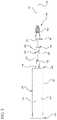
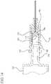
- FIG. 1illustrates a medical device assembly according to one or more embodiments of the invention shown attached to a fluid storage container;
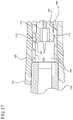
- FIG. 2shows an exploded view of the assembly of FIG. 1 ;
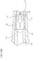
- FIG. 3is an exploded cross-sectional view of the hub, second indicating element and fluid storage container shown in FIG. 1 taken along line 3 - 3 ;
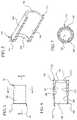
- FIG. 4is an enlarged view of the second indicating element shown in FIG. 2 ;
- FIG. 5is a perspective cross-sectional view of the second indicating element shown in FIG. 4 taken along line 5 - 5 ;
- FIG. 6is an enlarged sectional view of the second indicating element shown in FIG. 3 ;
- FIG. 7is a cross-sectional view of the second indicating element shown in FIG. 4 taken along line 7 - 7 ;
- FIG. 8is a cross-sectional view of an alternative embodiment of the second indicating element
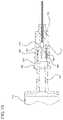
- FIG. 9Ais an enlarged sectional view of the hub shown in FIG. 3 ;
- FIG. 9Bis an enlarged sectional view of a hub according to an alternative embodiment
- FIG. 10is a cross-sectional view of the hub, second indicating element and the fluid storage container shown in FIG. 3 partially assembled;
- FIG. 11is an enlarged view of FIG. 10 ;
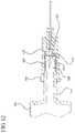
- FIG. 12illustrates FIG. 10 after application of an initial proximally directed force on the hub relative to the fluid storage container
- FIG. 13is an enlarged view of FIG. 12 ;
- FIG. 14illustrates FIG. 12 after continued application of a proximally directed force on the hub relative to the fluid storage container
- FIG. 15is an enlarged view of FIG. 14 ;
- FIG. 16illustrates FIG. 13 after the hub and the fluid storage container are in fluid-tight engagement
- FIG. 17is an enlarged view of FIG. 16 ;
- FIG. 18Ais an cross-sectional view of the second indicating element of FIG. 8 advancing distally past an alternative embodiment of the hub upon application of a proximally directed force on the hub relative to the fluid storage container;
- FIG. 18Bis a cross-sectional view of the second indicating element of FIG. 8 advancing distally past the alternative embodiment of the hub of FIG. 18A upon continued application of a proximally directed force on the hub relative to the fluid storage container;
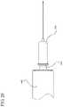
- FIG. 19illustrates a partially assembled view of a medical device according to a second embodiment of the invention.
- FIG. 20shows the medical device of FIG. 19 in an optimal assembly
- FIG. 21shows the medical device of FIG. 19 in an over-tightened assembly
- FIG. 22shows the medical device of FIG. 19 in an under-tightened assembly.
- One aspect of the present inventionprovides for a medical device assembly that may be connected or attached in fluid-tight engagement with a fluid storage container.
- the medical device assembly of one or more embodimentsmay utilize a first indicating element and/or a second indicating element as a means for indicating fluid-tight engagement with a fluid storage container.
- One or more embodiments of the medical device assemblyinclude a hub and means for indicating application of a force on the hub sufficient to result in fluid tight engagement with a fluid storage container.
- the means for indicatingmay be utilized during engagement of the medical device assembly and the fluid storage container in a luer slip configuration.
- the embodiments of the medical device assemblies described hereinmay be used with an optional needle cannula and/or an optional needle tip cap.
- FIGS. 1-21illustrate a medical device assembly according to one or more embodiments.
- medical device assemblymay be used with fluid storage containers such as syringe barrels, needleless IV sets, or other devices that can be used to store and/or transfer medication or other liquid.
- the fluid storage containerincludes an opening providing access to the contents of the container.
- the openingmay include a male luer fitting or may be otherwise configured for use with the medical device assembly.
- FIGS. 1-21illustrate a medical device assembly according to the invention, including a hub 160 having means for indicating application of a force on the hub sufficient to result in fluid tight engagement with a fluid storage container 140 .
- the means for indicating application of such a forceforms at least two contact points with the hub during application of the force.
- the means for indicating application of such a forceincludes a first indicating element 170 attached to or integrally formed with the hub and/or a second indicating element 180 disposed within the hub 160 .
- FIGS. 1-7show an embodiment of the medical device assembly that includes an optional needle cannula 132 attached to a hub 160 .
- FIG. 1-7also show an optional fluid storage container 140 in the form of a syringe barrel attached to the hub to form a fluid delivery system 100 .
- the fluid storage container 140has a sidewall 142 with an inside surface 144 that defines a chamber 146 for holding the contents of the container, which may include medication.
- the container 140includes an open proximal end 141 and a distal end 149 and a distal wall 148 .
- the distal wall 148includes a luer tip 150 having an opening 152 in fluid communication with the chamber 146 .
- the fluid storage container 140may include a plunger rod 120 inserted into the proximal end 141 of the fluid storage container 140 . It is to be understood that the configuration shown is merely exemplary, and the components can be different in shape and size than shown.
- the hub 160 shown more clearly in FIG. 9Aincludes an open proximal end 161 and a distal end 169 that includes the optional needle cannula 132 having a lumen 134 therethrough.
- the hub 160includes a sidewall 164 extending from the distal end 169 toward the open proximal end 161 and defining a cavity 166 .
- the distal end 169includes a passageway 130 therethrough in fluid communication with the lumen 134 of the optional needle cannula 132 .
- a second indicating element 180is disposed within the cavity 166 of the hub 160 .
- the distal end 169 of the hub 160further includes a first indicating element 170 having a distal end 179 attached to the distal end 169 of the hub 160 and a free proximal end 171 extending proximally into the cavity 166 .
- the first indicating element 170is permanently attached to the distal end 169 of the hub.
- the first indicating element 170is integrally formed with the hub 160 .
- the first indicating element 170is a separate component that may be attached or affixed to the distal end 169 of the hub.
- the first indicating element 170 of one or more embodimentsis substantially free of threads and forms an interference fit engagement with the second indicating element 180 , as will be more fully described below.
- the first indicating element 170forms a recess 163 with the sidewall 164 .
- the recess 163may extend from the distal end 169 of the hub to the free proximal end 171 of the first indicating element 170 .
- the first indicating elementmay be in the form of a second sidewall formed coaxially with the sidewall 164 of the hub, forming peripheral recess with the sidewall 164 of the hub.
- the coaxially formed second sidewallmay encircle or surround the passageway 130 .
- the first indicating elementmay include a cantilevered beam attached to the distal end 169 of the hub adjacent to the passageway 130 and extending into the cavity 166 .
- the recess 163is shaped to receive the second indicating element 180 when the hub is attached to a fluid storage container.
- the first indicating element 170includes at least one protrusion 175 extending radially outwardly from the outer surface of the first indicating element 170 into the recess 163 .
- the protrusion 175may be a single extending portion or may be a ridge formed concentrically around the first indicating element 170 .
- the location of the protrusionmay be modified to indicate fluid tight connection with fluid storage containers having different shapes and for use with second indicating elements 180 with different sizes and shapes.
- the medical device of the inventionmay include a hub 260 with a needle cannula 132 wherein the hub 260 is configured to incorporate one or more components to prevent contamination and accidental sticking and/or to protect the needle cannula 132 , such as a needle tip cap (not shown).
- the hub 260includes a distal end 269 with a passageway 230 therethrough, an open proximal end 261 , and a sidewall 264 extending from the distal end 269 and the proximal end 261 that defines a cavity 266 .
- the hub 260includes first indicating element 270 for indicating fluid-tight engagement between the hub 260 and a fluid storage container.
- the hub 260includes a coaxial wall 267 formed around the sidewall 264 at the distal end 269 .
- the coaxial wall 267forms a channel 268 for receiving a needle tip cap (not shown).
- the needle cannula 132may be made of various materials known in the art, including metals such as stainless steel, and may be held in the hub 160 or 260 using known manufacturing methods. For example, adhesives may be used to hold the needle.
- the hubmay be manufactured using known methods such as injection molding and may be made of injection moldable plastic such as polypropylene, polyethylene, polycarbonate and combinations thereof.
- the needle cannula and hubmay also be integrally formed of thermoplastic material.
- the sidewall 164 of the hubmay also be shaped to attach to a variety of fluid storage containers.
- the shape of the hubmay be modified to form an interference fit with a selected fluid storage container in a luer slip configuration.
- the hubmay be shaped to have a frusto-conical shape to form a luer slip configuration with the tip of a fluid storage container (as shown in FIGS. 9-17 ).
- the hubmay also be shaped to be used with standard luer slip fittings or other luer fittings known in the art.
- the sidewall 164 of the hub 160may be free of any threads for engagement with the fluid storage container in a luer lock configuration.
- the second indicating element 180is disposed within the cavity 166 of the hub 160 .
- the second indicating element 180includes an open proximal end 181 and an open distal end 189 .
- the second indicating element 180also includes a hollow body 182 having an axial length and an inside surface 184 defining a hollow interior 186 extending from the distal end 189 to the proximal end 181 .
- the second indicating element 180is shaped and positioned to ensure or to facilitate fluid-tight engagement of the hub 160 and a fluid storage container.
- the second indicating element 180is positioned within the cavity 166 of the hub 160 so that when the hub 160 is placed over the opening of a fluid storage container, for example, the tip 150 of a fluid storage container 140 , the proximal end 181 of the second indicating element 180 abuts the tip 150 , while the distal end 189 of the second indicating element 180 is adjacent to and/or contacts the proximal end 171 of the first indicating element 170 , as more clearly shown in FIGS. 10-11 .
- the tip 150is disposed adjacent to the proximal end 181 of the second indicating element 180 and does not enter the hollow interior 186 of the second indicating element 180 during assembly of the fluid storage container 140 and the hub 160 .
- the second indicating element 180is shaped and configured to require a user to apply a pre-determined force on the hub 160 in the proximal direction toward the fluid storage container 140 or a pre-determined force on the fluid storage container 140 in the distal direction toward the hub 160 to allow the second indicating element 180 to advance distally over the first indicating element 170 and the protrusion 175 disposed on the outer surface of the first indicating element 170 , as shown in FIGS. 10-17 .
- Application of this pre-determined forceresults in the displacement of the second indicating element 180 within the cavity 166 into the recess 163 , thereby indicating the point at which the hub 160 and the tip 150 form a fluid-tight engagement.
- the protrusion 175is disposed on the outer surface of the first indicating element 170 and may be modified in shape and location to adjust the pre-determined force required to form a fluid-tight engagement between the hub 160 and the tip 150 .
- the height of the protrusion 175may be increased to increase the total amount of force needed to be applied on the hub 160 and/or the fluid storage container 140 to form a fluid-tight engagement between the hub 160 and the tip 150 .
- the increased height of the protrusion 170increases resistance to advancement of the second indicating element 180 in the distal direction over the first indicating element 170 . This increased resistance indicates to the user that more force is required to form such engagement between the hub 160 and the tip 150 .
- Advancement of the second indicating element 180 into the recess 163 over the first indicating element 170indicates sufficient force has been applied to the hub 160 and/or fluid storage container 140 to create fluid-tight engagement.
- the second indicating element 180is shaped to fit over the first indicating element 170 of the hub 160 .
- the hollow body 182 of the second indicating element 180may be elongate and solid.
- the inside surface 184 of the hollow body 182 adjacent to the distal end 189 and/or the proximal end 181 of the second indicating element 180includes a solid, continuous or uninterrupted perimeter 190 that defines the open distal end 189 and/or at the open proximal end 181 .
- the inside surface 184 and/or the outside surface of body 182may be free of internal threads.
- the inside surface 184is shaped to form a hollow interior 186 that can envelope the first indicating element 170 as the second indicating element 180 advances distally over the first indicating element 170 .
- the body 182 extending between the open proximal end 181 and the open distal end 189 of the second indicating element 180need not be solid and may include openings that allow access to the hollow interior 186 from the open distal end 189 , open proximal end 181 or along the body 182 , however, the solid perimeter 190 formed by the inside surface 184 adjacent to the open distal end 189 and/or the proximal end 181 is continuous.
- the second indicating element 180is disposed within the cavity 166 of the hub as a separate piece and is not attached or connected to the hub before engagement of the hub to a fluid storage container.
- the second indicating element 180may be shaped such that it fits inside the cavity 166 of the hub 160 .
- the second indicating element 180may be shaped so it is slidable and/or moveable within the cavity 166 of the hub 160 .
- the second indicating element 180may be shaped so that it is not rotatable in any direction within the cavity 166 of the hub 160 .
- the second indicating element 180is shaped to allow rotation only around the axis extending from the open distal end 189 and the open proximal end 181 .
- the outside surface of body 182has a cross-sectional width that permits the second indicating element 180 to fit within the cavity 166 of the hub 160 and the inside surface 184 at the perimeter has a cross-sectional width that permits the second indicating element 180 to slide distally over the first indicating element 170 .
- the body 182has a thickness that allows the second indicating element 180 to advance distally within the recess 163 of the hub 160 .
- the body 182 shown more clearly in FIGS. 4-7forms a cylinder having a solid circular cross-section along its entire length and includes a continuous solid perimeter 190 at the distal end 189 and the proximal end 181 .
- first and second indicating elementsmay have cross-sections of any shape.
- the first and/or second indicating elementmay have a cross-section such that the inside surface of the first and/or second indicating element forms a non-circular shape and the outside surface of the first and/or second indicating element forms a circular shape.
- the first and/or second indicating elementmay have a cross-section such that the inside surface forms a circular shape and the outside surface forms a non-circular shape.
- the medical device assemblymay include a means to control orientation of the second indicating element with respect to the first indicating element.
- the outside surface of the body 182includes an outwardly radially extending lip 183 or projection disposed at one or more points along the length of the outside surface of the body 182 .
- the lip 183may be disposed near the distal end 181 and/or proximal end 189 of the second indicating element 180 .
- Alternative embodimentsmay include a second indicating element 180 may include a plurality of lips disposed along the outside surface of the body 182 .
- the lip 183may be a single protruding point extending outwardly radially from the outside surface of the body 182 or may be peripherally formed around the outside surface of the body 182 , as shown in FIGS. 4-7 .
- the lip 183increases the thickness of the body 182 .
- the cross-sectional width of the second indicating element 180 at lipis greater than the cross-sectional width of the second indicating element 180 at the exterior surface of the second indicating element 180 at remaining portions of the body 182 .
- the increased cross-sectional width formed by the lip 183forms a interference or friction fit interaction with the sidewall 164 of the hub 160 so that the second indicating element 180 is retained within the cavity 166 of the hub 160 before engagement of the medical device assembly and a fluid storage container, when forming a fluid delivery system 100 .
- the inside surface 184has a cross-sectional width, which is measured at the inside surface 184 , that forms an interference fit with the outside surface of the first indicating element 170 .
- the inside surface 184 of one or more embodiments of the second indicating element 180defines a gradually tapered cross-sectional width that forms a narrowed portion at one or more points along the length of the inside surface 184 .
- the inside surface 184may be shaped to include a first cross-sectional region defining the narrowest cross-sectional width.
- the inside surface 184may be shaped to include a second cross-sectional region that defines a cross-sectional width measured at the inside surface 184 that is greater than the cross-sectional width at the first cross-sectional region that extends distally and/or proximally from the first cross-sectional region.
- the second cross-sectional regionmay include a cross-sectional width that increases as it extends distally and/or proximally from the first cross-sectional region.
- the inside surface 184may be shaped to include a third cross-sectional region that has a cross-sectional width measured at the inside surface 184 that is greater than the cross-sectional width of the first and second cross-sectional regions.
- the third cross-sectional regionmay be disposed adjacent to the proximal end 181 and/or the distal end 189 of the second indicating element 180 .
- the third cross-sectional regionmay have a cross-sectional width that increases or decreases along its length.
- the third cross-sectional regionmay be disposed adjacent to the second cross-sectional region and the proximal end 181 and/or distal end 189 of the second indicating element 180 .
- the second indicating element 180includes a circular cross-section and has an inside surface 184 defining a first diameter region 185 that may have a narrowed cross-sectional width or diameter measured along the circumference of the inside surface at one or more points along the axial length of the body 182 .
- the first diameter region 185is a tapered portion that has a cross-sectional width that gradually decreases, with respect to the cross-sectional width defined by the remaining portions of the inside surface 184 of the second indicating element 180 .
- the second indicating element 180may also include a second diameter region 187 at one or more points along the axial length of the inside surface 184 that extends from the first diameter region 185 toward the distal end 189 and/or the proximal end 181 of the second indicating element 180 .
- the inside surface 184includes a first diameter region 185 adjacent the open distal end 189 of the second indicating element 180 and a second diameter region 187 having an axial length extending from the first diameter region 185 to the open proximal end 181 such that the diameter of the inside surface 184 increases along the second diameter region 187 from the first diameter region 185 toward the proximal end 181 .
- the second diameter region 180forms a ramp or ramped portion having a proximally increasing diameter measured at the inside surface 184 .
- the first diameter region 185is disposed adjacent to the proximal end 181 of the second indicating element 180 and the second diameter region 187 extends distally toward the distal end 189 of the second indicating element 180 .
- the inside surface 184 of the second indicating element 180may also include a third diameter region 188 that has a diameter greater than the diameter at the first diameter region 185 and the diameter at the second diameter region 187 .
- the third diameter region 188has a diameter that is constant along its entire length.
- the third diameter region 188has a diameter that increases along its length in the proximal or distal direction.
- the second diameter region 187has a diameter that is greater than the diameter of the first diameter region 185 and a diameter that is smaller than the diameter of the third diameter region 188 .
- the second indicating element 180includes a first diameter region 185 disposed adjacent to the distal end 189 , second diameter region 187 disposed proximally adjacent to the first diameter region 185 and a third diameter region 188 disposed proximally adjacent to the second diameter region 187 and extending toward the proximal end 181 .
- the diameter of the second diameter region 187increases as it extends from the first diameter region 185 to the third diameter region 188 .
- the third diameter region 188has a diameter that increases along its length in the distal or proximal direction.
- the third diameter region 188has a diameter measured at the inside surface 184 that is sized to prevent the tip 150 of the fluid storage container 140 from entering or being inserted into the hollow interior 186 of the second indicating element.
- the third diameter region 188is sufficiently rigid to provide support to the second indicating element 180 to prevent deformation during use or, more specifically, upon application of a force on the hub and/or fluid storage container that causes the second indicating element 180 to advance distally over the first indicating element 170 and/or the protrusion 175 .
- the third diameter region 188 of a specific embodimentmay also have a diameter equal to or larger than the diameter of the first indicating element 170 and/or the diameter formed by the protrusion 175 and the first indicating element 170 .
- the diameter of the third diameter region 188is greater than the diameter formed by the protrusion 175 such that the third diameter region 188 is permitted to advance distally past the protrusion 175 .
- advancement of the third diameter region 188 distally past the protrusion 175indicates fluid tight engagement of the medical device and the fluid storage container and that no residual or additional force should be applied to the hub 160 in the proximal direction toward the fluid storage container or to the fluid storage container 140 in the distal direction toward the hub 160 .
- the first diameter region 185forms an entrance angle 178 at the distal end 189 of the second indicating element 180 that permits the second indicating element 180 to move distally over the first indicating element 170 , while forming line contact with the first indicating element 170 and the protrusion 175 .
- line contactmay be formed between the entrance angle 178 and the first indicating element 170 .
- the entrance angle 178also forms line contact with the protrusion 175 .
- line contactmay be formed between the entrance angle 178 and the first diameter region 185 and the first indicating element 170 and the protrusion 175 .
- the second indicating element 180forms one or more line contact interactions with the first indicating element 180 and/or protrusion 175 as the second indicating element 180 enters the recess 163 and slides distally over the first indicating element 170 .
- one or more line contact interactionsare formed from the point at which the first indicating element 170 contacts the entrance angle 178 of the second indicating element 180 .
- the firsts indicating element 170bends radially inwardly and permits the second indicating element 180 to further advance distally into the recess 163 while line contact is maintained between the first indicating element 170 and the second indicating element 180 .
- the second indicating element 180continues to advance distally past the first indicating element 170 and forms one or more line contact interactions when the first indicating element 170 and/or protrusion 175 contacts the first diameter region 185 of the second indicating element 180 , as shown in FIGS. 14-15 .
- one or more line contact interactionsare formed as the first indicating element 170 and/or protrusion 175 contacts the second diameter region 187 and/or the third diameter region 188 of the second indicating element 180 , as shown in FIGS. 16-17 .
- line contactis no longer maintained.
- the protrusion 175retains the second indicating element 180 within the recess 163 by preventing 180 and, specifically the first diameter portion 185 , from moving in the proximal direction.
- the entrance angle 178 formed between first diameter region 185 at the distal end 189 of the second indicating element 180has a radius that is larger than the height of the protrusion 185 .
- the larger radius of the second indicating elementensures the second indicating element 180 advances smoothly distally past the protrusion 175
- the solid perimeter 190 formed by inside surface 184 of the second indicating element at the distal end 189 and the proximal end 181maintains its shape or resists deformation as the second indicating element 180 moves distally over the first indicating element 170 and protrusion 175 .
- the solid perimeter 190 of the second indicating element 180forms a contact area between the inside surface 184 and the outside surface of the first indicating element 170 and/or the protrusion 175 .
- the solid perimeter 190maintains a circular shape as the second indicating element 180 moves distally over the first indicating element 170 and protrusion 175 and forms a circular contact area between the inside surface 184 and the outside surface of the first indicating element 170 .
- the rigidity of the solid perimeter 190ensures that the second indicating element 180 maintains its shape and thus allows use of the medical device assembly with fluid-storage containers that require higher or increased engagement force to form a fluid-tight engagement between the medical device assembly and the fluid storage container 140 .
- Interruptions in the solid perimeter 190 formed by the inside surface 184 at the distal end 189 and/or proximal end 181 of the second indicating element 180cause the second indicating element 180 to deform as it moves distally over the first indicating element 170 and protrusion 175 , causing variability in engagement forces required to connect the hub 160 and fluid storage container 140 in fluid-tight engagement.
- the presence of interruptions in the solid perimeter 190 formed by the inside surface 184 of a second indicating element 180 having a cylindrical shapemay cause the body 182 to deform such that the cross-section of the body 182 changes from a circular shape to an ellipsoidal shape.
- interruptions in the solid perimeter 190 formed by the inside surface 184may deform the body such that the cross-section of the body 182 changes from a regular polygonal to an irregular polygonal.
- the tapered geometry of the embodiments of the second indicating element 180allows the formation of line contact interactions between the second indicating element 180 and the first indicating element 170 .
- Line contact interactionsdistribute the stress and pressure applied to both surfaces among more than one point or location. This reduces the stress applied to any single point thereby reducing likelihood that a defect in one or both of the surfaces will result in a failure of the structural integrity of either part.
- Medical device assemblieswhich do not have a tapered second indicating element are likely to form only point or surface contacts with the first indicating element.
- the inside surface 184 of the second indicating element 180is further contoured to maintain line-contact with the first indicating element 170 as the second indicating element 180 moves distally over the first indicating element 170 and the protrusion 175 .
- the second diameter region 187advances distally past the protrusion 175 , there is no contact between the protrusion 175 and second indicating element 180 .
- the entrance angle 178 , first diameter region 185 , second diameter region 187 and the third diameter region 188are shaped to create line contact between the second indicating element 180 and the first indicating element 170 and the protrusion 175 throughout the range of distal movement of the first diameter region 185 and second diameter region 187 distally past the protrusion 175 of the first indicating element
- the second indicating element 380has a body 382 extending from an open distal end 389 to an open proximal end 381 .
- the body 382includes an inside surface 384 defining a hollow interior 386 and a lip 383 outwardly radially extending from the outside surface of the body 382 .
- the inside surface 384includes a tapered portion 385 adjacent the open distal end 389 , a ramped portion 387 proximally adjacent to the tapered diameter portion 385 , an enlarged portion 388 adjacent the open proximal end 381 .
- the ramped portion 387has an axial length extending from the tapered portion 385 toward the enlarged portion 388 such that the cross-sectional width measured at the inside surface 384 increases along the ramped portion 387 from the tapered portion 385 toward the enlarged portion 388 .
- the length of the ramped portion 387is reduced in length such that the change in cross-sectional width measured at the inside surface 384 at the tapered portion 385 and the enlarged portion 388 is more abrupt or less gradual.
- fluid-tight engagement of the hub and the fluid storage deviceprovides more noticeable tactile feedback, while maintaining one or more line contact interactions between the first indicating element and the second indicating element 380 .
- the second indicating element of one or more embodiments described hereinmay be formed from a plastic material or from metal.
- the second indicating elementis injection molded using an injection moldable plastic such as polypropylene, polyethylene, polycarbonate or combinations thereof.
- the inside surface of the second indicating elementforms one or more line contact interactions as the second indicating element advances distally over the first indicating element. It is believed that line contact interactions reduce sensitivity to molding defects on the protrusion and/or the first indicating element. The line contact interactions are also believed to reduce deformation of the inside surface of embodiments of second indicating element as it passes distally over the protrusion.
- Modifying the shape of the componentsfor example, by utilizing the tapered design for the second indicating element described herein, mitigated these problems.
- the solid perimeter 190 design of the second indicating elementfurther improved manufacturability and allowed the selection and use of more elastic materials, which reduces the dependency on exact dimensions.
- the surface finishes of the outside surface of the first indicating element and the inside surface of the second indicating elementcan be modified to ensure more consistent interaction between the first and second indicating elements.
- second indicating elements 180 manufactured by injection moldingare substantially free of structural projections caused by other manufacturing methods that have limited application based on the material used.
- Such structural projectionsinclude projections that extend radially outwardly from the body at the distal end and/or proximal end, that may cause skiving of the hub or other increases in the engagement force required to form a fluid-tight engagement between the hub and tip.
- the sidewall 164 of the hub, the first indicating element 170 and/or the second indicating element 180may also be shaped and configured to reduce dead space or unoccupied space between the tip 150 and the passageway 130 .
- gapswere included in the perimeter at the openings of the second indicating element as a result of limited production means and materials. In such embodiments the open gaps resulted in increased dead space within the hub when attached to a fluid storage device.
- Embodiments of the second indicating element 180which include a solid and continuous body 182 reduce dead space within the cavity when the hub is attached to the fluid-storage device.
- the length of the first indicating element 170may be adjusted to permit the distal end of one or more embodiments of the second indicating element described herein to advance into the recess 163 formed between the first indicating element 170 and the sidewall 164 until it contacts the distal end 169 of the hub 160 .
- the length of the first indicating element 170 and the movement of the distal end of the second indicating elementprovide additional indication of fluid tight engagement between the hub 160 and the tip or fluid storage container by preventing the user from applying a force on the hub in the proximal direction or the fluid storage container in the distal direction.
- the length of the first indicating element 170may be adjusted to allow the use of second indicating elements having different lengths.
- the length of the first indicating element 170is sufficiently long to permit the second indicating element to advance distally past the protrusion 175 without interference or being blocked by the distal end 169 of the hub 160 .
- the length of the body 182 of the second indicating element 180may be reduced to reduce dead space between the tip 150 and the passageway 130
- the sidewall 164may also be adjusted or modified to reduce or increase the length and/or dimensions of the recess 163 , however, the length of the recess 163 should permit the second indicating element 180 to advance distally past the protrusion 175 .
- FIGS. 18A and 18BAn alternative embodiment of the hub 360 is shown in FIGS. 18A and 18B .
- the hub 360includes a sidewall 364 and a first indicating element 370 that is flexible and which forms a recess 363 with the sidewall 364 .
- the first indicating element 380flexes inwardly toward the passageway 330 to permit the body 382 of the second indicating element to advance distally over the first indicating element 370 and/or protrusion 375 into the recess 363 .
- the ability of the first indicating element 370 to resume its original shapecreates a tactile feedback for the user of fluid-tight engagement between the hub 360 and the fluid storage container.
- the ramped portion 387 of the second indicating element 280has a reduced length that results in a more dramatic increase in diameter or cross-sectional width measured at various points along the inside surface of the second indicating element.
- the first indicating elementis permitted to flex and relax more rapidly thereby producing enhanced tactile feedback for the user of fluid-tight engagement between the hub and the fluid storage container.
- the body of the second indicating elementmay be flexible and may flex as the second indicating element advances distally over the first indicating element and/or protrusion.
- the solid perimetermay be rigid and retains its shape as the second indicating element advances distally over the first indicating element.
- one of the first indicating element and the second indicating elementhas greater flexibility that the other of the first indicating element and the second indicating element.
- one of the first indicating element and second indicating elementis flexible while the other of the two is relatively inflexible in comparison to the flexible element.
- the first indicating element and/or the second indicating elementcan provide tactile feedback through the use of different materials with different flexibility or rigidity that permit the flexed element to resume its original shape after the second indicating element advances distally past the protrusion of the first indicating element.
- a second aspect of the present inventionpertains to an indication system for use with the medical device assemblies described herein during attachment to a fluid storage container, for example, the fluid storage container 140 shown in FIG. 1 .
- the indication systemprovides visual indication of optimal engagement or optimal degree of press-fit or interference fit has been achieved during connection of the hub, for example, the hub 160 shown in FIG. 1 , and the fluid storage container.
- the indication systemprovides visual indication of over-tightening, under-tightening and optimal tightening of the luer slip connection between hub 160 and the fluid storage container 140 . Over-tightening of the hub 160 and fluid storage container luer slip may cause excessive compressive force at the joint or mating interface between the hub 160 and fluid storage container 140 .
- the indication system of the embodiment shown in FIGS. 19-22includes a visual indicator 400 that is added to the fluid storage container 440 , for example, along the circumference of the tip or opening of the fluid storage container 440 .
- the visual indicatoris a colored region that is printed or over-molded onto the fluid storage container.
- Other means known in the artmay be utilized to apply or form the visual indicator on the fluid storage container 440 .
- a forceis applied to the hub 460 in the proximal direction relative to the fluid storage container 440 .
- the position of the hub 460 relative to the visual indicator 400indicates whether adequate force has been applied to the hub to obtain optimal tightening. As shown more clearly in FIG.
- FIG. 21illustrates overlap of the visual indicator 400 and hub 460 indicating an over-tightened connection between the hub 460 and the fluid storage container 440 .
- FIG. 22illustrates a space between the visual indicator 400 and the hub 460 , indicating an under-tightened connection between the hub 460 and the fluid storage container 440 .
- the visual indicator 400includes three separate stripes (not shown) formed at three different locations from near the opening of the fluid storage container and proximally along the length of the fluid-storage.
- the three stripesmay have different colors.
- the first stripe disposed closest to the opening of the fluid storage containeris the first stripe and may be red in color
- the second stripe disposed proximally adjacent to the first stripemay be green in color
- the third stripe disposed proximally adjacent to the second stripemay be yellow in color.
- the indication system of FIGS. 19-22may be useful in providing visual indication of fluid-tight engagement between the medical assemblies described herein that provide reduced tactile feedback of fluid-tight engagement.
- the indication system of FIGS. 19-22may also be utilized with embodiments with enhanced tactile feedback to provide an additional indication of fluid-tight engagement between the medical device assembly and the fluid storage container.
- a third aspect of the present inventionpertains to methods of using the medical devices described herein.
- the methodincludes providing a hub including a sidewall having an inside surface defining a cavity, an open proximal end, a distal end having an opening therethrough in fluid communication with the cavity and a second indicating element disposed within the cavity.
- the methodfurther includes positioning the hub such that the open proximal end is aligned with the opening of a fluid storage container and applying a proximally directed force on the hub or applying a distally directed force on the fluid storage container such that the opening of the fluid storage container is disposed within the cavity and abuts the second indicating element.
- the methodfurther includes applying a continuous force in the proximal direction on the hub and/or in the distal direction on the fluid storage container to force the second indicating element to advance distally further into the cavity and engage with the hub.
- the methodincludes applying a continuous force on the hub in the proximal direction toward the fluid storage container and/or on the fluid storage container in the distal direction toward the hub such that the second indicating element envelopes the first indicating element and enters into the recess formed between the first indicating element and the hub, until the hub and fluid storage device are in fluid-tight engagement.
Landscapes
- Health & Medical Sciences (AREA)
- Vascular Medicine (AREA)
- Engineering & Computer Science (AREA)
- Anesthesiology (AREA)
- Biomedical Technology (AREA)
- Heart & Thoracic Surgery (AREA)
- Hematology (AREA)
- Life Sciences & Earth Sciences (AREA)
- Animal Behavior & Ethology (AREA)
- General Health & Medical Sciences (AREA)
- Public Health (AREA)
- Veterinary Medicine (AREA)
- Infusion, Injection, And Reservoir Apparatuses (AREA)
- Medical Preparation Storing Or Oral Administration Devices (AREA)
Abstract
Description
Claims (8)
Priority Applications (1)
| Application Number | Priority Date | Filing Date | Title |
|---|---|---|---|
| US16/587,673US11478589B2 (en) | 2009-07-30 | 2019-09-30 | Medical device assembly |
Applications Claiming Priority (4)
| Application Number | Priority Date | Filing Date | Title |
|---|---|---|---|
| US12/512,532US8915890B2 (en) | 2009-07-30 | 2009-07-30 | Medical device assembly |
| US14/537,999US9789265B2 (en) | 2009-07-30 | 2014-11-11 | Medical device assembly |
| US15/784,896US10426899B2 (en) | 2009-07-30 | 2017-10-16 | Medical device assembly |
| US16/587,673US11478589B2 (en) | 2009-07-30 | 2019-09-30 | Medical device assembly |
Related Parent Applications (1)
| Application Number | Title | Priority Date | Filing Date |
|---|---|---|---|
| US15/784,896DivisionUS10426899B2 (en) | 2009-07-30 | 2017-10-16 | Medical device assembly |
Publications (2)
| Publication Number | Publication Date |
|---|---|
| US20200023142A1 US20200023142A1 (en) | 2020-01-23 |
| US11478589B2true US11478589B2 (en) | 2022-10-25 |
Family
ID=42735592
Family Applications (4)
| Application Number | Title | Priority Date | Filing Date |
|---|---|---|---|
| US12/512,532Active2032-10-29US8915890B2 (en) | 2009-07-30 | 2009-07-30 | Medical device assembly |
| US14/537,999Active2030-03-20US9789265B2 (en) | 2009-07-30 | 2014-11-11 | Medical device assembly |
| US15/784,896ActiveUS10426899B2 (en) | 2009-07-30 | 2017-10-16 | Medical device assembly |
| US16/587,673Active2030-05-02US11478589B2 (en) | 2009-07-30 | 2019-09-30 | Medical device assembly |
Family Applications Before (3)
| Application Number | Title | Priority Date | Filing Date |
|---|---|---|---|
| US12/512,532Active2032-10-29US8915890B2 (en) | 2009-07-30 | 2009-07-30 | Medical device assembly |
| US14/537,999Active2030-03-20US9789265B2 (en) | 2009-07-30 | 2014-11-11 | Medical device assembly |
| US15/784,896ActiveUS10426899B2 (en) | 2009-07-30 | 2017-10-16 | Medical device assembly |
Country Status (10)
| Country | Link |
|---|---|
| US (4) | US8915890B2 (en) |
| EP (1) | EP2459256B1 (en) |
| JP (1) | JP5638610B2 (en) |
| CN (1) | CN102470222B (en) |
| AU (1) | AU2010276586B2 (en) |
| CA (1) | CA2768192C (en) |
| ES (1) | ES2549772T3 (en) |
| IN (1) | IN2012DN00381A (en) |
| SG (2) | SG10201403797PA (en) |
| WO (1) | WO2011014444A1 (en) |
Families Citing this family (23)
| Publication number | Priority date | Publication date | Assignee | Title |
|---|---|---|---|---|
| US11090444B2 (en) | 2018-06-15 | 2021-08-17 | James T. Doubet | Syringe adapter for medication |
| US11097058B2 (en) | 2018-06-15 | 2021-08-24 | James T. Doubet | Syringe adapter for medication |
| US11337894B2 (en) | 2018-06-15 | 2022-05-24 | James T. Doubet | Syringe adapter for animal medication |
| US10709850B2 (en) | 2018-06-15 | 2020-07-14 | James T. Doubet | Syringe adapter for medication |
| DK2240222T3 (en) | 2008-01-11 | 2018-06-25 | Ucb Biopharma Sprl | SYSTEMS FOR THE ADMINISTRATION OF PHARMACEUTICALS FOR PATIENTS WITH RHEUMATOID ARTHRITIS |
| EP3581223B1 (en) | 2008-07-18 | 2024-07-10 | UCB Biopharma SRL | Systems for automatically administering medication |
| USD641078S1 (en) | 2008-12-29 | 2011-07-05 | Ucb Pharma, S.A. | Medical syringe with needle tip cap |
| US8915890B2 (en) | 2009-07-30 | 2014-12-23 | Becton, Dickinson And Company | Medical device assembly |
| NL2009180C2 (en)* | 2012-07-12 | 2014-01-14 | Pharma Group B V | Low residual volume syringe/conduit combination and syringe for such a syringe/conduit combination. |
| AR098613A1 (en) | 2013-12-06 | 2016-06-01 | Genentech Inc | APPLIANCES AND METHODS FOR THE ADMINISTRATION OF MEDICINES IN LOW VOLUMES |
| US10155091B2 (en)* | 2014-07-11 | 2018-12-18 | Stat Medical Devices, Inc. | Pen needle tip and method of making and using the same |
| DE102014114403A1 (en)* | 2014-10-02 | 2016-04-07 | Gerresheimer Regensburg Gmbh | Plug for placement on a connection element of a medical syringe |
| JP2016163642A (en)* | 2015-03-06 | 2016-09-08 | 大成化工株式会社 | Barrel with needle and syringe having the same |
| WO2017070959A1 (en)* | 2015-10-30 | 2017-05-04 | 项文 | Device for controlling puncture depth and hiding needle and usage method thereof |
| HUE054412T2 (en) | 2016-05-16 | 2021-09-28 | Haemonetics Corp | Sealer-less plasma bottle and top for same |
| US11648179B2 (en) | 2016-05-16 | 2023-05-16 | Haemonetics Corporation | Sealer-less plasma bottle and top for same |
| USD890925S1 (en) | 2018-06-15 | 2020-07-21 | James T. Doubet | Syringe adapter for medication |
| US20190388625A1 (en) | 2018-06-15 | 2019-12-26 | James T. Doubet | Syringe adapter for medication |
| WO2020086332A1 (en)* | 2018-10-21 | 2020-04-30 | Doubet James T | Syringe adapter for medication |
| USD958929S1 (en)* | 2018-11-21 | 2022-07-26 | Inter-Med, Inc. | Minimal waste dispensing tip |
| CA3061396A1 (en)* | 2018-11-30 | 2020-05-30 | Becton, Dickinson And Company | Tactile features to guide user interaction with fluid connector |
| EP3902569B1 (en)* | 2018-12-28 | 2025-09-24 | ASP Global Manufacturing GmbH | A treatment indicator, a method of production thereof, and a method of use thereof |
| EP3868429A1 (en)* | 2020-02-18 | 2021-08-25 | Becton Dickinson France | An adaptor for a medical container, a medical container comprising said adaptor, and a method for manufacturing said adaptor |
Citations (123)
| Publication number | Priority date | Publication date | Assignee | Title |
|---|---|---|---|---|
| US791802A (en) | 1904-05-16 | 1905-06-06 | Justin De Lisle | Hypodermic syringe. |
| US1012700A (en) | 1910-12-23 | 1911-12-26 | Joseph Payne | Syringe. |
| FR567078A (en) | 1923-06-06 | 1924-02-25 | Improvements to needles for injection or aspiration of liquids | |
| US1522198A (en) | 1922-08-09 | 1925-01-06 | Ernest H Marcy | Hypodermic unit |
| US1524242A (en) | 1924-08-26 | 1925-01-27 | George N Hein | Needle-retaining device for syringes |
| US1591762A (en) | 1926-04-03 | 1926-07-06 | Faichney Instr Corp | Fastener for needle mounts |
| US1683350A (en) | 1926-10-04 | 1928-09-04 | George N Hein | Lock for hypodermic needles and the like |
| US1683349A (en) | 1926-10-04 | 1928-09-04 | George N Hein | Hypodermic syringe and means for retaining same |
| US2020111A (en) | 1934-06-16 | 1935-11-05 | Eisele Logan | Detachable locking means for hypodermic syringe needles |
| US2034294A (en) | 1934-04-27 | 1936-03-17 | George N Hein | Needle syringe equipment |
| US2088338A (en) | 1935-03-06 | 1937-07-27 | Isidor A Popper | Hypodermic needle and novel hub for the same |
| US2577556A (en) | 1950-02-04 | 1951-12-04 | Macgregor Instr Company | Cartridge syringe, including a cannula attaching chuck |
| US2699777A (en) | 1952-05-02 | 1955-01-18 | Voorhorst Johan | Injection syringe |
| US2764978A (en) | 1953-11-13 | 1956-10-02 | S & R J Everett & Co Ltd | Locking device for hypodermic needles |
| US2806473A (en) | 1953-11-23 | 1957-09-17 | Mac Gregor Instr Company | Hypodermic and like syringes, needles for use therewith, and connections therebetween |
| US2828743A (en) | 1957-06-17 | 1958-04-01 | American Home Prod | Snap-on cartridge-needle unit |
| US2834346A (en) | 1955-06-06 | 1958-05-13 | Becton Dickinson Co | Syringe and hub locking assembly |
| US2855927A (en) | 1955-05-05 | 1958-10-14 | Henderson Edward | Hypodermic needle mount |
| US2902995A (en) | 1954-10-11 | 1959-09-08 | Abbott Lab | Hypodermic syringe and needle hub structure |
| US3043304A (en) | 1959-03-30 | 1962-07-10 | Brunswick Corp | Hypodermic needle mount |
| US3450135A (en) | 1966-10-06 | 1969-06-17 | Stanley J Sarnoff | Cartridge assembly including ribbed hub |
| US3469581A (en) | 1967-10-23 | 1969-09-30 | Burron Medical Prod Inc | Syringe and needle adapter assembly |
| US3472227A (en) | 1965-08-18 | 1969-10-14 | Burron Medical Prod Inc | Hypodermic needle |
| US3491757A (en) | 1966-12-30 | 1970-01-27 | Raul Olvera Arce | Hypodermic syringe with non-turning tip connector |
| US3527217A (en) | 1968-01-18 | 1970-09-08 | William A Gettig | Hypodermic hub |
| US3633944A (en) | 1970-11-23 | 1972-01-11 | Jacob J Hamburg | Tube coupling |
| US3736932A (en)* | 1972-02-15 | 1973-06-05 | Sherwood Medical Ind Inc | Injection apparatus with filter |
| US3977403A (en) | 1975-02-24 | 1976-08-31 | The Kendall Company | Catheter adapter |
| US3994295A (en) | 1975-08-22 | 1976-11-30 | Wulff Goldwyn L | Hypodermic syringe needle mounting |
| JPS5283294A (en) | 1975-12-30 | 1977-07-12 | Nippon Signal Co Ltd:The | Guide device for ticket examining machines |
| US4040421A (en) | 1975-04-04 | 1977-08-09 | Becton, Dickinson And Company | Hypodermic syringe and attached needle assembly |
| JPS535891A (en) | 1976-07-06 | 1978-01-19 | Becton Dickinson Co | Hypodermic injector |
| US4187848A (en) | 1977-07-18 | 1980-02-12 | The Kendall Company | Adapter assembly |
| US4281653A (en) | 1978-10-16 | 1981-08-04 | Immuno Aktiengesellschaft Fur Chemisch-Medizinische Produkte | Combined ampule-oneway injection syringe |
| US4369781A (en) | 1981-02-11 | 1983-01-25 | Sherwood Medical Industries Inc. | Luer connector |
| JPS592750B2 (en) | 1981-12-25 | 1984-01-20 | 株式会社プラズマシステム | plasma processing equipment |
| US4430080A (en) | 1982-06-09 | 1984-02-07 | Becton, Dickinson And Company | Syringe assembly with snap-fit components |
| US4457749A (en) | 1982-04-19 | 1984-07-03 | Baxter Travenol Laboratories, Inc. | Shield for connectors |
| US4490142A (en) | 1983-08-22 | 1984-12-25 | Silvern Rubin D | Carpule syringe with rapidly acting mechanism for controllably _positively retaining the hub of a hypodermic needle |
| US4547194A (en) | 1984-03-16 | 1985-10-15 | Moorehead Harvey R | Hub assemblies and extensions for indwelling catheter tubes and method |
| US4589871A (en) | 1985-03-29 | 1986-05-20 | Becton, Dickinson And Company | Syringe barrel |
| US4613329A (en) | 1983-09-30 | 1986-09-23 | Sherwood Medical Company | Catheter placement device |
| US4664656A (en) | 1984-04-26 | 1987-05-12 | Andre Taddei | Injection syringe |
| US4675020A (en) | 1985-10-09 | 1987-06-23 | Kendall Mcgaw Laboratories, Inc. | Connector |
| US4676530A (en) | 1983-04-07 | 1987-06-30 | Warner-Lambert Company | Coupling assembly for use in fluid flow systems |
| US4723945A (en) | 1984-05-03 | 1988-02-09 | Bunder Glas Gmbh | Hypodermic syringe |
| US4747839A (en) | 1986-12-17 | 1988-05-31 | Survival Technology, Inc. | Disposable hypodermic syringe with plastic snap-on needle hub and heat shrink seal therefor |
| DE8805331U1 (en) | 1988-04-22 | 1988-09-08 | Müller, Wolfgang, Dr.med., 2308 Preetz | Needle holder with clamping device for disposable syringes |
| US4781701A (en)* | 1986-07-11 | 1988-11-01 | Arzneimittel Gmbh Apotheker Vetter & Co. Ravensburg | Syringe for medical purposes |
| US4822343A (en) | 1987-09-21 | 1989-04-18 | Louise Beiser | Blood collection device with ejectable tips |
| US4842592A (en) | 1987-05-06 | 1989-06-27 | Teleflex Incorporated | Connector assembly |
| US4927417A (en) | 1988-07-07 | 1990-05-22 | Schneider Medical Technologies, Inc. | Safety sleeve adapter |
| US4929243A (en) | 1988-02-09 | 1990-05-29 | B. Braun Melsungen Ag | Catheter coupling |
| US4984580A (en) | 1986-04-21 | 1991-01-15 | Thomas Wanamaker | Blood drawing apparatus |
| WO1991003269A1 (en) | 1989-08-28 | 1991-03-21 | Townsend Controls Pty. Ltd. | Safety syringe |
| US5026355A (en) | 1990-01-23 | 1991-06-25 | Becton Dickinson And Company | Needle and hub assembly with needle contacting member |
| US5047021A (en) | 1989-08-29 | 1991-09-10 | Utterberg David S | Male luer lock medical fitting |
| US5053015A (en) | 1989-08-30 | 1991-10-01 | The Kendall Company | Locking catheter adapter |
| US5066287A (en) | 1988-07-27 | 1991-11-19 | Ryan Medical, Inc. | Safety multiple sample rear adapter assembly |
| US5069225A (en) | 1988-09-28 | 1991-12-03 | Terumo Kabushiki Kaisha | Blood collection and/or injection device and double-ended medical needle and holder therefor |
| US5135514A (en) | 1988-02-10 | 1992-08-04 | Astra Pharmaceuticals Pty Ltd | Plastic cartridge and syringe |
| US5188620A (en) | 1988-01-25 | 1993-02-23 | Baxter International Inc. | Pre-slit injection site and associated cannula |
| US5209740A (en) | 1991-11-22 | 1993-05-11 | Abbott Laboratories | Catheter adapter having retention notches |
| US5221272A (en) | 1991-12-03 | 1993-06-22 | Safegrip, Inc. | Unified medical fluid system |
| US5257832A (en) | 1992-05-07 | 1993-11-02 | The Regents Of The University Of California | Universal tube connector |
| US5280967A (en) | 1992-03-27 | 1994-01-25 | Donald Travis | Device for indicating the proper installation of fittings |
| US5312377A (en) | 1993-03-29 | 1994-05-17 | Dalton Michael J | Tapered luer connector |
| US5348544A (en) | 1993-11-24 | 1994-09-20 | Becton, Dickinson And Company | Single-handedly actuatable safety shield for needles |
| JPH0731679A (en) | 1993-07-23 | 1995-02-03 | Nissho Corp | Syringe assembly |
| US5405330A (en) | 1994-04-15 | 1995-04-11 | Zunitch; Daniel | Syringe needle holder |
| US5405340A (en) | 1992-10-07 | 1995-04-11 | Abbott Laboratories | Threaded securing apparatus for flow connectors |
| US5456675A (en) | 1993-04-08 | 1995-10-10 | Fresenius Ag | Port cannula arrangement for connection to a port |
| US5458580A (en) | 1993-03-22 | 1995-10-17 | Hajishoreh; Kaveh-Karimi | Syringe apparatus |
| US5466223A (en) | 1994-06-20 | 1995-11-14 | Becton, Dickinson And Company | Needle assembly having single-handedly activatable needle barrier |
| EP0696460A2 (en) | 1994-08-10 | 1996-02-14 | Becton, Dickinson and Company | Valved PRN adapter for medical access devices |
| JPH0857058A (en) | 1994-08-10 | 1996-03-05 | Becton Dickinson & Co | Adaptor with valve for medical apparatus |
| US5569209A (en) | 1994-12-21 | 1996-10-29 | Jemm Tran-Safe Systems, Inc. | Needleless transfer system |
| US5584817A (en) | 1994-07-15 | 1996-12-17 | A.P.I.S. Medical B.V. | Prefilled injection syringe assembly |
| US5591143A (en) | 1993-04-02 | 1997-01-07 | Medrad Inc. | Luer connector with torque indicator |
| US5611786A (en) | 1993-07-09 | 1997-03-18 | Disetronic Ag | Needle system fastening mechanism |
| US5616136A (en) | 1995-01-09 | 1997-04-01 | Med-Safe Systems, Inc. | Quick release needle removal apparatus |
| US5624405A (en)* | 1994-05-27 | 1997-04-29 | Nissho Corporation | Prefilled syringe and syringe tip assembly |
| US5681295A (en) | 1996-07-03 | 1997-10-28 | Becton, Dickinson And Company | Needle shield assembly having a single-use cannula lock |
| US5713876A (en) | 1995-06-07 | 1998-02-03 | Johnson & Johnson Medical, Inc. | Catheter release mechanism |
| US5733265A (en) | 1996-09-25 | 1998-03-31 | Becton Dickinson And Company | Shielded needle assembly |
| US5772643A (en) | 1996-02-29 | 1998-06-30 | Becton Dickinson And Company | Barbed luer adapter |
| US5810768A (en) | 1995-06-07 | 1998-09-22 | Icu Medical, Inc. | Medical connector |
| US5810782A (en) | 1993-03-12 | 1998-09-22 | Saito; Yoshikuni | Hub for syringe, connecting structure of hub, syringe, syringe assembly and method of assembling syringe assembly |
| US5830189A (en) | 1995-06-07 | 1998-11-03 | Johnson & Johnson Medical, Inc. | Catheter hub to nose engagement |
| US5836919A (en) | 1996-05-23 | 1998-11-17 | Solopak Pharmaceuticals, Inc. | Cap assembly |
| US5851201A (en) | 1996-01-19 | 1998-12-22 | Acacia Laboratories, Inc. | Luer connector |
| US5855568A (en) | 1996-11-22 | 1999-01-05 | Liebel-Flarsheim Company | Angiographic syringe and luer connector |
| US5913846A (en) | 1996-06-13 | 1999-06-22 | Becton, Dickinson And Company | Shielded needle assembly |
| US5919169A (en) | 1997-06-23 | 1999-07-06 | Grams; Guenter | Cannula lock and seal mechanism |
| US5925020A (en) | 1994-11-22 | 1999-07-20 | Becton, Dickinson And Company | Needle point barrier |
| US5968020A (en) | 1993-03-12 | 1999-10-19 | Saito; Yoshikuni | Syringe assembly |
| JP3031444B2 (en) | 1992-04-30 | 2000-04-10 | 京セラ株式会社 | Developer concentration detector |
| JP2000116781A (en) | 1998-10-20 | 2000-04-25 | Mitsubishi Pencil Co Ltd | Joining structure of syringe and injection needle |
| JP2000116796A (en) | 1998-10-16 | 2000-04-25 | Terumo Corp | Tube connecting member |
| US6063068A (en) | 1997-12-04 | 2000-05-16 | Baxter International Inc. | Vial connecting device for a sliding reconstitution device with seal |
| US6132402A (en) | 1999-02-02 | 2000-10-17 | Bioform Inc. | Storage and delivery device for a catheter or needle |
| US6135771A (en)* | 1997-12-02 | 2000-10-24 | Centrix, Inc. | Dental cartridge having an attachable delivery portion |
| US6224576B1 (en) | 1999-11-04 | 2001-05-01 | Specialized Health Products, Inc. | Safety device for a needle having two sharpened ends |
| US6338200B1 (en) | 1999-10-08 | 2002-01-15 | Baxa Corporation | Syringe dose identification system |
| JP2002515311A (en) | 1998-05-20 | 2002-05-28 | バクスター・インターナショナル・インコーポレイテッド | Needleless connector |
| US6436076B1 (en) | 2000-12-19 | 2002-08-20 | Fu-Yu Hsu | Needle holder positioning structure for a safety syringe |
| US20020138045A1 (en) | 2001-03-20 | 2002-09-26 | Moen Michael E. | Quick connect fitting |
| JP2003505158A (en) | 1999-07-27 | 2003-02-12 | アラリス メディカル システムズ インコーポレイテッド | Needleless medical connector with expandable valve mechanism |
| JP2003088587A (en) | 2001-05-04 | 2003-03-25 | Becton Dickinson & Co | Passively activated safety needle |
| US6629960B2 (en) | 2000-05-18 | 2003-10-07 | Integrated Implant Systems, Ll.C. | Needle hub for medical instrument |
| US6629774B1 (en) | 1999-08-11 | 2003-10-07 | Tah Industries, Inc. | Static mixer nozzle and attachment accessory configuration |
| US6709428B2 (en) | 2000-05-26 | 2004-03-23 | Baxter International, Inc. | Needle design and manufacturing method for medical applications |
| US20040189007A1 (en) | 2003-03-31 | 2004-09-30 | Olich Jack M. | Quick operation bottom sealing connectors for flexible tubing and flared tubing |
| US20040220533A1 (en) | 2003-05-02 | 2004-11-04 | Caizza Richard J. | Controlled release structure for attaching medical devices |
| US6971390B1 (en) | 2002-02-05 | 2005-12-06 | C. R. Bard, Inc. | Catheter connection and repair system |
| US20060082151A1 (en) | 2004-10-20 | 2006-04-20 | Persohn Matthew M | Coupling assembly with connection indicator |
| US7080672B2 (en) | 2002-08-22 | 2006-07-25 | Sherwood Services Ag | Sliding seal adapter for a feeding system |
| US7115114B2 (en) | 2003-05-02 | 2006-10-03 | Becton, Dickinson And Company | Medical device having releasable retainer |
| US20070214692A1 (en) | 2006-03-16 | 2007-09-20 | Ferrara Kenneth D | System for facilitating preparation of medication doses |
| WO2008050158A2 (en) | 2006-10-27 | 2008-05-02 | Barry Peter Liversidge | Medical needle safety devices |
| WO2009143640A1 (en) | 2008-05-24 | 2009-12-03 | Tecpharma Licensing Ag | Mixing device for a two-chamber ampoule |
| US20110028909A1 (en) | 2009-07-30 | 2011-02-03 | Becton, Dickinson And Company | Medical Device Assembly |
| US8801689B2 (en) | 2007-08-01 | 2014-08-12 | Hospira, Inc. | Medicament admixing system |
Family Cites Families (13)
| Publication number | Priority date | Publication date | Assignee | Title |
|---|---|---|---|---|
| JPS5114934A (en) | 1974-07-30 | 1976-02-05 | Saiden Kagaku Kk | EKIJOSETSU CHAKURYOKUKYOKAHIFUKU SOSEIBUTSU |
| DK415174A (en)* | 1974-08-02 | 1976-02-03 | Asican As | SPRAYER AND SPRAY CYLINDER AND CANNULLE THEREOF |
| JPS5283294U (en) | 1975-12-16 | 1977-06-21 | ||
| JPS545891A (en) | 1977-06-16 | 1979-01-17 | Mitsui Toatsu Chem Inc | Catalyst for producing phthalic anhydride |
| JPS585891Y2 (en) | 1978-09-11 | 1983-02-01 | 株式会社ノーリツ | Boiler |
| JPS585891A (en) | 1981-07-03 | 1983-01-13 | 武蔵株式会社 | Counter exclusively used for election |
| JPH08732B2 (en) | 1987-01-16 | 1996-01-10 | 三菱マテリアル株式会社 | Manufacturing method of cubic boron nitride based ultra high pressure sintered body for cutting tool |
| JPH0331444A (en) | 1989-06-29 | 1991-02-12 | Aichi Steel Works Ltd | Tough and hard non-heattreated steel for hot forging |
| JPH0731679B2 (en) | 1989-09-29 | 1995-04-10 | キヤノン株式会社 | Character processor |
| JP3031444U (en) | 1996-05-21 | 1996-11-29 | タキゲン製造株式会社 | Flat handle device |
| US20020072715A1 (en)* | 1998-08-28 | 2002-06-13 | Newby C. Mark | Needle assembly |
| US6599269B1 (en)* | 1999-12-03 | 2003-07-29 | Becton Dickinson And Company | Single-use syringe |
| FR2836832B1 (en)* | 2002-03-08 | 2005-02-04 | Optis France Sa | CONNECTION ASSEMBLY FOR MEDICAL USE FOR THE TRANSFER OF FLUIDS |
- 2009
- 2009-07-30USUS12/512,532patent/US8915890B2/enactiveActive
- 2010
- 2010-07-26ININ381DEN2012patent/IN2012DN00381A/enunknown
- 2010-07-26ESES10739773.9Tpatent/ES2549772T3/enactiveActive
- 2010-07-26SGSG10201403797PApatent/SG10201403797PA/enunknown
- 2010-07-26WOPCT/US2010/043200patent/WO2011014444A1/enactiveApplication Filing
- 2010-07-26CACA2768192Apatent/CA2768192C/enactiveActive
- 2010-07-26AUAU2010276586Apatent/AU2010276586B2/enactiveActive
- 2010-07-26EPEP10739773.9Apatent/EP2459256B1/enactiveActive
- 2010-07-26CNCN2010800336347Apatent/CN102470222B/enactiveActive
- 2010-07-26JPJP2012522928Apatent/JP5638610B2/enactiveActive
- 2010-07-26SGSG2012002424Apatent/SG177639A1/enunknown
- 2014
- 2014-11-11USUS14/537,999patent/US9789265B2/enactiveActive
- 2017
- 2017-10-16USUS15/784,896patent/US10426899B2/enactiveActive
- 2019
- 2019-09-30USUS16/587,673patent/US11478589B2/enactiveActive
Patent Citations (142)
| Publication number | Priority date | Publication date | Assignee | Title |
|---|---|---|---|---|
| US791802A (en) | 1904-05-16 | 1905-06-06 | Justin De Lisle | Hypodermic syringe. |
| US1012700A (en) | 1910-12-23 | 1911-12-26 | Joseph Payne | Syringe. |
| US1522198A (en) | 1922-08-09 | 1925-01-06 | Ernest H Marcy | Hypodermic unit |
| FR567078A (en) | 1923-06-06 | 1924-02-25 | Improvements to needles for injection or aspiration of liquids | |
| US1524242A (en) | 1924-08-26 | 1925-01-27 | George N Hein | Needle-retaining device for syringes |
| US1591762A (en) | 1926-04-03 | 1926-07-06 | Faichney Instr Corp | Fastener for needle mounts |
| US1683350A (en) | 1926-10-04 | 1928-09-04 | George N Hein | Lock for hypodermic needles and the like |
| US1683349A (en) | 1926-10-04 | 1928-09-04 | George N Hein | Hypodermic syringe and means for retaining same |
| US2034294A (en) | 1934-04-27 | 1936-03-17 | George N Hein | Needle syringe equipment |
| US2020111A (en) | 1934-06-16 | 1935-11-05 | Eisele Logan | Detachable locking means for hypodermic syringe needles |
| US2088338A (en) | 1935-03-06 | 1937-07-27 | Isidor A Popper | Hypodermic needle and novel hub for the same |
| US2577556A (en) | 1950-02-04 | 1951-12-04 | Macgregor Instr Company | Cartridge syringe, including a cannula attaching chuck |
| US2699777A (en) | 1952-05-02 | 1955-01-18 | Voorhorst Johan | Injection syringe |
| US2764978A (en) | 1953-11-13 | 1956-10-02 | S & R J Everett & Co Ltd | Locking device for hypodermic needles |
| US2806473A (en) | 1953-11-23 | 1957-09-17 | Mac Gregor Instr Company | Hypodermic and like syringes, needles for use therewith, and connections therebetween |
| US2902995A (en) | 1954-10-11 | 1959-09-08 | Abbott Lab | Hypodermic syringe and needle hub structure |
| US2855927A (en) | 1955-05-05 | 1958-10-14 | Henderson Edward | Hypodermic needle mount |
| US2834346A (en) | 1955-06-06 | 1958-05-13 | Becton Dickinson Co | Syringe and hub locking assembly |
| US2828743A (en) | 1957-06-17 | 1958-04-01 | American Home Prod | Snap-on cartridge-needle unit |
| US3043304A (en) | 1959-03-30 | 1962-07-10 | Brunswick Corp | Hypodermic needle mount |
| US3472227A (en) | 1965-08-18 | 1969-10-14 | Burron Medical Prod Inc | Hypodermic needle |
| US3450135A (en) | 1966-10-06 | 1969-06-17 | Stanley J Sarnoff | Cartridge assembly including ribbed hub |
| US3491757A (en) | 1966-12-30 | 1970-01-27 | Raul Olvera Arce | Hypodermic syringe with non-turning tip connector |
| US3469581A (en) | 1967-10-23 | 1969-09-30 | Burron Medical Prod Inc | Syringe and needle adapter assembly |
| US3527217A (en) | 1968-01-18 | 1970-09-08 | William A Gettig | Hypodermic hub |
| US3633944A (en) | 1970-11-23 | 1972-01-11 | Jacob J Hamburg | Tube coupling |
| US3736932A (en)* | 1972-02-15 | 1973-06-05 | Sherwood Medical Ind Inc | Injection apparatus with filter |
| US3977403A (en) | 1975-02-24 | 1976-08-31 | The Kendall Company | Catheter adapter |
| US4040421A (en) | 1975-04-04 | 1977-08-09 | Becton, Dickinson And Company | Hypodermic syringe and attached needle assembly |
| US3994295A (en) | 1975-08-22 | 1976-11-30 | Wulff Goldwyn L | Hypodermic syringe needle mounting |
| JPS5283294A (en) | 1975-12-30 | 1977-07-12 | Nippon Signal Co Ltd:The | Guide device for ticket examining machines |
| JPS535891A (en) | 1976-07-06 | 1978-01-19 | Becton Dickinson Co | Hypodermic injector |
| GB1574187A (en) | 1976-07-06 | 1980-09-03 | Becton Dickinson Co | Low-dose hypodermic syringe |
| US4187848A (en) | 1977-07-18 | 1980-02-12 | The Kendall Company | Adapter assembly |
| US4281653A (en) | 1978-10-16 | 1981-08-04 | Immuno Aktiengesellschaft Fur Chemisch-Medizinische Produkte | Combined ampule-oneway injection syringe |
| US4369781A (en) | 1981-02-11 | 1983-01-25 | Sherwood Medical Industries Inc. | Luer connector |
| JPS592750B2 (en) | 1981-12-25 | 1984-01-20 | 株式会社プラズマシステム | plasma processing equipment |
| US4457749A (en) | 1982-04-19 | 1984-07-03 | Baxter Travenol Laboratories, Inc. | Shield for connectors |
| US4430080A (en) | 1982-06-09 | 1984-02-07 | Becton, Dickinson And Company | Syringe assembly with snap-fit components |
| US4676530A (en) | 1983-04-07 | 1987-06-30 | Warner-Lambert Company | Coupling assembly for use in fluid flow systems |
| US4490142A (en) | 1983-08-22 | 1984-12-25 | Silvern Rubin D | Carpule syringe with rapidly acting mechanism for controllably _positively retaining the hub of a hypodermic needle |
| US4613329A (en) | 1983-09-30 | 1986-09-23 | Sherwood Medical Company | Catheter placement device |
| US4547194A (en) | 1984-03-16 | 1985-10-15 | Moorehead Harvey R | Hub assemblies and extensions for indwelling catheter tubes and method |
| US4664656A (en) | 1984-04-26 | 1987-05-12 | Andre Taddei | Injection syringe |
| US4723945A (en) | 1984-05-03 | 1988-02-09 | Bunder Glas Gmbh | Hypodermic syringe |
| US4589871A (en) | 1985-03-29 | 1986-05-20 | Becton, Dickinson And Company | Syringe barrel |
| US4675020A (en) | 1985-10-09 | 1987-06-23 | Kendall Mcgaw Laboratories, Inc. | Connector |
| US4984580A (en) | 1986-04-21 | 1991-01-15 | Thomas Wanamaker | Blood drawing apparatus |
| US4781701A (en)* | 1986-07-11 | 1988-11-01 | Arzneimittel Gmbh Apotheker Vetter & Co. Ravensburg | Syringe for medical purposes |
| US4747839A (en) | 1986-12-17 | 1988-05-31 | Survival Technology, Inc. | Disposable hypodermic syringe with plastic snap-on needle hub and heat shrink seal therefor |
| US4842592A (en) | 1987-05-06 | 1989-06-27 | Teleflex Incorporated | Connector assembly |
| US4822343A (en) | 1987-09-21 | 1989-04-18 | Louise Beiser | Blood collection device with ejectable tips |
| US5188620A (en) | 1988-01-25 | 1993-02-23 | Baxter International Inc. | Pre-slit injection site and associated cannula |
| US4929243A (en) | 1988-02-09 | 1990-05-29 | B. Braun Melsungen Ag | Catheter coupling |
| US5135514A (en) | 1988-02-10 | 1992-08-04 | Astra Pharmaceuticals Pty Ltd | Plastic cartridge and syringe |
| DE8805331U1 (en) | 1988-04-22 | 1988-09-08 | Müller, Wolfgang, Dr.med., 2308 Preetz | Needle holder with clamping device for disposable syringes |
| US4927417A (en) | 1988-07-07 | 1990-05-22 | Schneider Medical Technologies, Inc. | Safety sleeve adapter |
| US5066287A (en) | 1988-07-27 | 1991-11-19 | Ryan Medical, Inc. | Safety multiple sample rear adapter assembly |
| US5069225A (en) | 1988-09-28 | 1991-12-03 | Terumo Kabushiki Kaisha | Blood collection and/or injection device and double-ended medical needle and holder therefor |
| WO1991003269A1 (en) | 1989-08-28 | 1991-03-21 | Townsend Controls Pty. Ltd. | Safety syringe |
| US5047021A (en) | 1989-08-29 | 1991-09-10 | Utterberg David S | Male luer lock medical fitting |
| US5053015A (en) | 1989-08-30 | 1991-10-01 | The Kendall Company | Locking catheter adapter |
| US5026355A (en) | 1990-01-23 | 1991-06-25 | Becton Dickinson And Company | Needle and hub assembly with needle contacting member |
| US5209740A (en) | 1991-11-22 | 1993-05-11 | Abbott Laboratories | Catheter adapter having retention notches |
| US5221272A (en) | 1991-12-03 | 1993-06-22 | Safegrip, Inc. | Unified medical fluid system |
| US5280967A (en) | 1992-03-27 | 1994-01-25 | Donald Travis | Device for indicating the proper installation of fittings |
| JP3031444B2 (en) | 1992-04-30 | 2000-04-10 | 京セラ株式会社 | Developer concentration detector |
| US5257832A (en) | 1992-05-07 | 1993-11-02 | The Regents Of The University Of California | Universal tube connector |
| US5405340A (en) | 1992-10-07 | 1995-04-11 | Abbott Laboratories | Threaded securing apparatus for flow connectors |
| US5968020A (en) | 1993-03-12 | 1999-10-19 | Saito; Yoshikuni | Syringe assembly |
| US5810782A (en) | 1993-03-12 | 1998-09-22 | Saito; Yoshikuni | Hub for syringe, connecting structure of hub, syringe, syringe assembly and method of assembling syringe assembly |
| US5458580A (en) | 1993-03-22 | 1995-10-17 | Hajishoreh; Kaveh-Karimi | Syringe apparatus |
| US5312377A (en) | 1993-03-29 | 1994-05-17 | Dalton Michael J | Tapered luer connector |
| US5591143A (en) | 1993-04-02 | 1997-01-07 | Medrad Inc. | Luer connector with torque indicator |
| JPH07303697A (en) | 1993-04-08 | 1995-11-21 | Fresenius Ag | Port cannula device |
| US5456675A (en) | 1993-04-08 | 1995-10-10 | Fresenius Ag | Port cannula arrangement for connection to a port |
| US5611786A (en) | 1993-07-09 | 1997-03-18 | Disetronic Ag | Needle system fastening mechanism |
| US5458577A (en) | 1993-07-23 | 1995-10-17 | Nissho Corporation | Composite syringe |
| JPH0731679A (en) | 1993-07-23 | 1995-02-03 | Nissho Corp | Syringe assembly |
| US5348544A (en) | 1993-11-24 | 1994-09-20 | Becton, Dickinson And Company | Single-handedly actuatable safety shield for needles |
| US5405330A (en) | 1994-04-15 | 1995-04-11 | Zunitch; Daniel | Syringe needle holder |
| US5624405A (en)* | 1994-05-27 | 1997-04-29 | Nissho Corporation | Prefilled syringe and syringe tip assembly |
| US5466223A (en) | 1994-06-20 | 1995-11-14 | Becton, Dickinson And Company | Needle assembly having single-handedly activatable needle barrier |
| JPH08732A (en) | 1994-06-20 | 1996-01-09 | Becton Dickinson & Co | Needle assembly with needle barrier which can be operated byone hand |
| US5584817A (en) | 1994-07-15 | 1996-12-17 | A.P.I.S. Medical B.V. | Prefilled injection syringe assembly |
| US5535771A (en) | 1994-08-10 | 1996-07-16 | Becton, Dickinson And Company | Valved PRN adapter for infusion devices |
| JPH0857058A (en) | 1994-08-10 | 1996-03-05 | Becton Dickinson & Co | Adaptor with valve for medical apparatus |
| EP0696460A2 (en) | 1994-08-10 | 1996-02-14 | Becton, Dickinson and Company | Valved PRN adapter for medical access devices |
| US5925020A (en) | 1994-11-22 | 1999-07-20 | Becton, Dickinson And Company | Needle point barrier |
| US5569209A (en) | 1994-12-21 | 1996-10-29 | Jemm Tran-Safe Systems, Inc. | Needleless transfer system |
| US5616136A (en) | 1995-01-09 | 1997-04-01 | Med-Safe Systems, Inc. | Quick release needle removal apparatus |
| US5637101A (en) | 1995-01-09 | 1997-06-10 | Med-Safe Systems, Inc. | Quick release needle coupling system |
| US5693028A (en) | 1995-01-09 | 1997-12-02 | Med-Safe Systems, Inc. | One hand needle release system |
| US5713876A (en) | 1995-06-07 | 1998-02-03 | Johnson & Johnson Medical, Inc. | Catheter release mechanism |
| US5830189A (en) | 1995-06-07 | 1998-11-03 | Johnson & Johnson Medical, Inc. | Catheter hub to nose engagement |
| JPH11507275A (en) | 1995-06-07 | 1999-06-29 | アイシーユー メディカル、インコーポレイテッド | Medical connector |
| US5810768A (en) | 1995-06-07 | 1998-09-22 | Icu Medical, Inc. | Medical connector |
| US5851201A (en) | 1996-01-19 | 1998-12-22 | Acacia Laboratories, Inc. | Luer connector |
| US6217560B1 (en) | 1996-01-19 | 2001-04-17 | Philip L. Ritger | Luer connector |
| US5772643A (en) | 1996-02-29 | 1998-06-30 | Becton Dickinson And Company | Barbed luer adapter |
| US5836919A (en) | 1996-05-23 | 1998-11-17 | Solopak Pharmaceuticals, Inc. | Cap assembly |
| US5913846A (en) | 1996-06-13 | 1999-06-22 | Becton, Dickinson And Company | Shielded needle assembly |
| US5681295A (en) | 1996-07-03 | 1997-10-28 | Becton, Dickinson And Company | Needle shield assembly having a single-use cannula lock |
| JPH10113392A (en) | 1996-09-25 | 1998-05-06 | Becton Dickinson & Co | Needle assembly having shield |
| US5733265A (en) | 1996-09-25 | 1998-03-31 | Becton Dickinson And Company | Shielded needle assembly |
| US5855568A (en) | 1996-11-22 | 1999-01-05 | Liebel-Flarsheim Company | Angiographic syringe and luer connector |
| US5919169A (en) | 1997-06-23 | 1999-07-06 | Grams; Guenter | Cannula lock and seal mechanism |
| US6135771A (en)* | 1997-12-02 | 2000-10-24 | Centrix, Inc. | Dental cartridge having an attachable delivery portion |
| US6063068A (en) | 1997-12-04 | 2000-05-16 | Baxter International Inc. | Vial connecting device for a sliding reconstitution device with seal |
| JP2002515311A (en) | 1998-05-20 | 2002-05-28 | バクスター・インターナショナル・インコーポレイテッド | Needleless connector |
| JP2000116796A (en) | 1998-10-16 | 2000-04-25 | Terumo Corp | Tube connecting member |
| JP2000116781A (en) | 1998-10-20 | 2000-04-25 | Mitsubishi Pencil Co Ltd | Joining structure of syringe and injection needle |
| US6132402A (en) | 1999-02-02 | 2000-10-17 | Bioform Inc. | Storage and delivery device for a catheter or needle |
| JP2003505158A (en) | 1999-07-27 | 2003-02-12 | アラリス メディカル システムズ インコーポレイテッド | Needleless medical connector with expandable valve mechanism |
| US6706022B1 (en) | 1999-07-27 | 2004-03-16 | Alaris Medical Systems, Inc. | Needleless medical connector with expandable valve mechanism |
| US6629774B1 (en) | 1999-08-11 | 2003-10-07 | Tah Industries, Inc. | Static mixer nozzle and attachment accessory configuration |
| US6338200B1 (en) | 1999-10-08 | 2002-01-15 | Baxa Corporation | Syringe dose identification system |
| US6224576B1 (en) | 1999-11-04 | 2001-05-01 | Specialized Health Products, Inc. | Safety device for a needle having two sharpened ends |
| US6629960B2 (en) | 2000-05-18 | 2003-10-07 | Integrated Implant Systems, Ll.C. | Needle hub for medical instrument |
| US6709428B2 (en) | 2000-05-26 | 2004-03-23 | Baxter International, Inc. | Needle design and manufacturing method for medical applications |
| US6436076B1 (en) | 2000-12-19 | 2002-08-20 | Fu-Yu Hsu | Needle holder positioning structure for a safety syringe |
| US20020138045A1 (en) | 2001-03-20 | 2002-09-26 | Moen Michael E. | Quick connect fitting |
| JP2003088587A (en) | 2001-05-04 | 2003-03-25 | Becton Dickinson & Co | Passively activated safety needle |
| EP1254677B1 (en) | 2001-05-04 | 2005-12-21 | Becton, Dickinson and Company | Passively activated safety needle |
| US6971390B1 (en) | 2002-02-05 | 2005-12-06 | C. R. Bard, Inc. | Catheter connection and repair system |
| US7080672B2 (en) | 2002-08-22 | 2006-07-25 | Sherwood Services Ag | Sliding seal adapter for a feeding system |
| US20040189007A1 (en) | 2003-03-31 | 2004-09-30 | Olich Jack M. | Quick operation bottom sealing connectors for flexible tubing and flared tubing |
| US20040220533A1 (en) | 2003-05-02 | 2004-11-04 | Caizza Richard J. | Controlled release structure for attaching medical devices |
| US7115114B2 (en) | 2003-05-02 | 2006-10-03 | Becton, Dickinson And Company | Medical device having releasable retainer |
| US7217258B2 (en) | 2003-05-02 | 2007-05-15 | Becton, Dickinson And Company | Controlled release structure for attaching medical devices |
| US20070173776A1 (en) | 2003-05-02 | 2007-07-26 | Becton, Dickinson And Company | Controlled release structure for attaching medical devices |
| US20070185461A1 (en) | 2003-05-02 | 2007-08-09 | Becton, Dickinson And Company | Controlled release structure for attaching medical devices |
| US20060082151A1 (en) | 2004-10-20 | 2006-04-20 | Persohn Matthew M | Coupling assembly with connection indicator |
| US20070214692A1 (en) | 2006-03-16 | 2007-09-20 | Ferrara Kenneth D | System for facilitating preparation of medication doses |
| WO2008050158A2 (en) | 2006-10-27 | 2008-05-02 | Barry Peter Liversidge | Medical needle safety devices |
| WO2008050158A3 (en) | 2006-10-27 | 2008-07-17 | Barry Peter Liversidge | Medical needle safety devices |
| US8801689B2 (en) | 2007-08-01 | 2014-08-12 | Hospira, Inc. | Medicament admixing system |
| WO2009143640A1 (en) | 2008-05-24 | 2009-12-03 | Tecpharma Licensing Ag | Mixing device for a two-chamber ampoule |
| US20110028909A1 (en) | 2009-07-30 | 2011-02-03 | Becton, Dickinson And Company | Medical Device Assembly |
| WO2011014444A1 (en) | 2009-07-30 | 2011-02-03 | Becton, Dickinson And Company | Medical device assembly |
| EP2459256A1 (en) | 2009-07-30 | 2012-06-06 | Becton, Dickinson and Company | Medical device assembly |
| US8915890B2 (en) | 2009-07-30 | 2014-12-23 | Becton, Dickinson And Company | Medical device assembly |
Non-Patent Citations (5)
| Title |
|---|
| Final Office Action in U.S. Appl. No. 12/512,532, dated Jul. 20, 2012, 15 pages. |
| IPRP & Written Opinion in PCT/US2010/043200, dated Jan. 31, 2012, 8 pgs. |
| Non-Final Office Action in U.S. Appl. No. 11/512,532, dated Feb. 16, 2012, 18 pages. |
| Non-Final Office Action in U.S. Appl. No. 12/512,532, dated Jun. 3, 2014, 10 pages. |
| PCT International Search Report in PCT/US043200 dated Oct. 5, 2010, 3 pages. |
Also Published As
| Publication number | Publication date |
|---|---|
| US20150065957A1 (en) | 2015-03-05 |
| CN102470222A (en) | 2012-05-23 |
| CN102470222B (en) | 2013-08-14 |
| EP2459256A1 (en) | 2012-06-06 |
| JP5638610B2 (en) | 2014-12-10 |
| US20110028909A1 (en) | 2011-02-03 |
| WO2011014444A1 (en) | 2011-02-03 |
| US10426899B2 (en) | 2019-10-01 |
| AU2010276586B2 (en) | 2015-04-23 |
| US9789265B2 (en) | 2017-10-17 |
| AU2010276586A1 (en) | 2012-02-23 |
| EP2459256B1 (en) | 2015-07-08 |
| US20180036493A1 (en) | 2018-02-08 |
| SG10201403797PA (en) | 2014-10-30 |
| SG177639A1 (en) | 2012-02-28 |
| IN2012DN00381A (en) | 2015-08-21 |
| US8915890B2 (en) | 2014-12-23 |
| CA2768192C (en) | 2017-01-17 |
| ES2549772T3 (en) | 2015-11-02 |
| CA2768192A1 (en) | 2011-02-03 |
| JP2013500770A (en) | 2013-01-10 |
| US20200023142A1 (en) | 2020-01-23 |
Similar Documents
| Publication | Publication Date | Title |
|---|---|---|
| US11478589B2 (en) | Medical device assembly | |
| US20230263964A1 (en) | Detachable Needle Syringe Having Reduced Dead Space | |
| US9101720B2 (en) | Prefilled syringe | |
| US7922958B2 (en) | Method of making an elongate syringe barrel | |
| EP0974372B1 (en) | Sealing rubber closure for syringe/container | |
| EP2678057B1 (en) | Flushing medical devices | |
| US12208062B2 (en) | Pharmaceutical adaptor system and pharmaceutical kit system | |
| AU2017265125B2 (en) | Medical device assembly | |
| EP4529938A1 (en) | Syringe plunger rod with variable diameter threaded connection | |
| US20250161571A1 (en) | Syringe With Minimal Internal Dead Volume | |
| EP4628125A1 (en) | Syringe plunger stopper with guidance-enabling internal cavity | |
| EP4316550A1 (en) | Tip cap assembly for an injection system | |
| AU2007281997B2 (en) | Detachable needle syringe having reduced dead space |
Legal Events
| Date | Code | Title | Description |
|---|---|---|---|
| FEPP | Fee payment procedure | Free format text:ENTITY STATUS SET TO UNDISCOUNTED (ORIGINAL EVENT CODE: BIG.); ENTITY STATUS OF PATENT OWNER: LARGE ENTITY | |
| STPP | Information on status: patent application and granting procedure in general | Free format text:APPLICATION DISPATCHED FROM PREEXAM, NOT YET DOCKETED | |
| AS | Assignment | Owner name:BECTON, DICKINSON AND COMPANY, NEW JERSEY Free format text:ASSIGNMENT OF ASSIGNORS INTEREST;ASSIGNORS:LUM, CHEE L.;ABID, WAHEED;DOUGLAS, PETER;AND OTHERS;REEL/FRAME:052309/0149 Effective date:20090826 | |
| STPP | Information on status: patent application and granting procedure in general | Free format text:DOCKETED NEW CASE - READY FOR EXAMINATION | |
| STPP | Information on status: patent application and granting procedure in general | Free format text:NON FINAL ACTION MAILED | |
| STPP | Information on status: patent application and granting procedure in general | Free format text:RESPONSE TO NON-FINAL OFFICE ACTION ENTERED AND FORWARDED TO EXAMINER | |
| STPP | Information on status: patent application and granting procedure in general | Free format text:FINAL REJECTION MAILED | |
| STPP | Information on status: patent application and granting procedure in general | Free format text:RESPONSE AFTER FINAL ACTION FORWARDED TO EXAMINER | |
| STPP | Information on status: patent application and granting procedure in general | Free format text:ADVISORY ACTION MAILED | |
| STPP | Information on status: patent application and granting procedure in general | Free format text:DOCKETED NEW CASE - READY FOR EXAMINATION | |
| STPP | Information on status: patent application and granting procedure in general | Free format text:NOTICE OF ALLOWANCE MAILED -- APPLICATION RECEIVED IN OFFICE OF PUBLICATIONS | |
| STPP | Information on status: patent application and granting procedure in general | Free format text:PUBLICATIONS -- ISSUE FEE PAYMENT RECEIVED | |
| STPP | Information on status: patent application and granting procedure in general | Free format text:PUBLICATIONS -- ISSUE FEE PAYMENT VERIFIED | |
| STCF | Information on status: patent grant | Free format text:PATENTED CASE |