US11478111B2 - Loading and transfer system/assembly for sheet material dispensers - Google Patents
Loading and transfer system/assembly for sheet material dispensersDownload PDFInfo
- Publication number
- US11478111B2 US11478111B2US16/893,516US202016893516AUS11478111B2US 11478111 B2US11478111 B2US 11478111B2US 202016893516 AUS202016893516 AUS 202016893516AUS 11478111 B2US11478111 B2US 11478111B2
- Authority
- US
- United States
- Prior art keywords
- sheet material
- dispenser
- roller
- feed roller
- cover
- Prior art date
- Legal status (The legal status is an assumption and is not a legal conclusion. Google has not performed a legal analysis and makes no representation as to the accuracy of the status listed.)
- Active, expires
Links
Images


Classifications
- A—HUMAN NECESSITIES
- A47—FURNITURE; DOMESTIC ARTICLES OR APPLIANCES; COFFEE MILLS; SPICE MILLS; SUCTION CLEANERS IN GENERAL
- A47K—SANITARY EQUIPMENT NOT OTHERWISE PROVIDED FOR; TOILET ACCESSORIES
- A47K10/00—Body-drying implements; Toilet paper; Holders therefor
- A47K10/24—Towel dispensers, e.g. for piled-up or folded textile towels; Toilet paper dispensers; Dispensers for piled-up or folded textile towels provided or not with devices for taking-up soiled towels as far as not mechanically driven
- A47K10/32—Dispensers for paper towels or toilet paper
- A47K10/34—Dispensers for paper towels or toilet paper dispensing from a web, e.g. with mechanical dispensing means
- A47K10/36—Dispensers for paper towels or toilet paper dispensing from a web, e.g. with mechanical dispensing means with mechanical dispensing, roll switching or cutting devices
- A47K10/3687—Dispensers for paper towels or toilet paper dispensing from a web, e.g. with mechanical dispensing means with mechanical dispensing, roll switching or cutting devices with one or more reserve rolls
- A—HUMAN NECESSITIES
- A47—FURNITURE; DOMESTIC ARTICLES OR APPLIANCES; COFFEE MILLS; SPICE MILLS; SUCTION CLEANERS IN GENERAL
- A47K—SANITARY EQUIPMENT NOT OTHERWISE PROVIDED FOR; TOILET ACCESSORIES
- A47K10/00—Body-drying implements; Toilet paper; Holders therefor
- A47K10/24—Towel dispensers, e.g. for piled-up or folded textile towels; Toilet paper dispensers; Dispensers for piled-up or folded textile towels provided or not with devices for taking-up soiled towels as far as not mechanically driven
- A47K10/32—Dispensers for paper towels or toilet paper
- A47K10/34—Dispensers for paper towels or toilet paper dispensing from a web, e.g. with mechanical dispensing means
- A47K10/38—Dispensers for paper towels or toilet paper dispensing from a web, e.g. with mechanical dispensing means the web being rolled up with or without tearing edge
- A—HUMAN NECESSITIES
- A47—FURNITURE; DOMESTIC ARTICLES OR APPLIANCES; COFFEE MILLS; SPICE MILLS; SUCTION CLEANERS IN GENERAL
- A47K—SANITARY EQUIPMENT NOT OTHERWISE PROVIDED FOR; TOILET ACCESSORIES
- A47K10/00—Body-drying implements; Toilet paper; Holders therefor
- A47K10/24—Towel dispensers, e.g. for piled-up or folded textile towels; Toilet paper dispensers; Dispensers for piled-up or folded textile towels provided or not with devices for taking-up soiled towels as far as not mechanically driven
- A47K10/32—Dispensers for paper towels or toilet paper
- A47K2010/3253—Dispensers for paper towels or toilet paper with one or more reserve rolls
- A—HUMAN NECESSITIES
- A47—FURNITURE; DOMESTIC ARTICLES OR APPLIANCES; COFFEE MILLS; SPICE MILLS; SUCTION CLEANERS IN GENERAL
- A47K—SANITARY EQUIPMENT NOT OTHERWISE PROVIDED FOR; TOILET ACCESSORIES
- A47K10/00—Body-drying implements; Toilet paper; Holders therefor
- A47K10/24—Towel dispensers, e.g. for piled-up or folded textile towels; Toilet paper dispensers; Dispensers for piled-up or folded textile towels provided or not with devices for taking-up soiled towels as far as not mechanically driven
- A47K10/32—Dispensers for paper towels or toilet paper
- A47K10/34—Dispensers for paper towels or toilet paper dispensing from a web, e.g. with mechanical dispensing means
- A47K10/36—Dispensers for paper towels or toilet paper dispensing from a web, e.g. with mechanical dispensing means with mechanical dispensing, roll switching or cutting devices
- A47K2010/3681—Dispensers for paper towels or toilet paper dispensing from a web, e.g. with mechanical dispensing means with mechanical dispensing, roll switching or cutting devices characterised by the way a new paper roll is loaded in the dispenser
Definitions
- the present disclosureis directed to dispensers for flexible sheet materials, and in particular, in one aspect, dispensers with a loading and/or transfer assemblies, mechanisms, or systems. Other aspects also are described.
- Dispensers for sheet materialsare commonly used in hospitals, restrooms, and other facilities. Loading sheet materials in such dispensers often can prove to be a difficult task. For example, personnel loading the dispensers may have to navigate the sheet material through relatively close or tight clearances between the operative elements, supports and other elements within the dispensers. This can take considerable time and sometimes results in tearing or ripping of the sheet material. Improper loading of the sheet material also is common and can cause jamming of the sheet material in the dispenser, thus resulting in significant down time for the sheet material dispenser.
- some dispenserscan have more than one supply of sheet material, e.g., multiple rolls of sheet material, for dispensing/feeding from the dispensers, and when one of the supply rolls is running low or has been fully dispensed, transfer of the feeding of sheet material to a new supply generally must be manually performed.
- feeding/dispensingis modified such that sheet material from multiple supplies may be dispensed or fed at the same time, i.e., double sheets may be dispensed simultaneously—potentially leading to waste of significant amounts of sheet material.
- the present disclosureis generally directed to a dispenser or dispenser assembly for rolled sheet materials, such as paper products including paper towels, tissue paper, etc. and/or other paper products.
- the dispenser assemblycan include a dispenser housing, with one or more support assemblies for supporting one or more supplies of sheet material disposed in or along the dispenser housing.
- the one or more supplies of sheet materialcan include a first supply roll and second supply roll of sheet material.
- the first or second supply of sheet materialcan include new, undispensed rolls of sheet material, partially dispensed rolls of sheet material, and/or stub rolls of sheet material.
- a stub roll of sheet materialgenerally includes a supply roll that has been substantially dispensed, e.g., a supply roll with less than about 50% to about 30% or less of its initial amount of sheet material remaining.
- the dispenser assemblyfurther can include a feed roller assembly including one or more feed rollers configured to engage and drive the sheet materials from the one or more supplies of sheet material.
- the feed roller(s)drive the sheet material along a discharge or feed path from the supply toward and through a discharge of the dispenser housing.
- the feed roller(s)can be automatically driven, e.g., by one or more powered drive mechanisms, such as a motor or other suitable actuator, or the feed roller(s) can be manually activated, such as by a rotatable knob, handle, or other suitable engagement and/or drive mechanism that can be engaged or rotated by an operator or user.
- the dispenser assemblyfurther can include a sheet material loading mechanism/assembly.
- the sheet material loading mechanism/assemblycan include a cover assembly that is movably connected to the dispenser housing.
- the cover assemblycan include a cover body rotatably or pivotably coupled to a front portion of the dispenser housing, e.g., at a first end of the cover body, and being movable between a closed position and an open position. In the closed position, the cover body at least partially surrounds and/or enclose the feed roller. In its open position, the cover body will be substantially spaced away from the feed roller, e.g., with the cover body extending out and away from the front portion of the dispenser.
- the sheet material loading mechanism/assemblyfurther includes a plurality of locking features or locking mechanisms (e.g., biased locking switches or other suitable locking mechanism/features) configured to lock or secure the cover assembly in its closed position.
- the locking features/mechanismscan be movable or actuatable to release the cover assembly and allow for the cover assembly to be moved to the opening position.
- the cover assemblycan be biased towards its open position.
- the loading mechanism/assemblycan include one or more biasing members (e.g., one or more springs, such as torsion springs, or other suitable biasing members) in communication with the cover body and the dispenser housing to bias the cover towards its open position.
- biasing memberse.g., one or more springs, such as torsion springs, or other suitable biasing members
- the cover assemblyfurther can include a cover roller, which, in some embodiments, can be a pressing or guide roller, connected thereto/integrated therewith.
- the cover rollercan be rotatably connected to the cover body at the second end of the cover body.
- the cover rollerfurther can be biased or urged (e.g., by one or more biasing members, such as springs or other suitable biasing members) to press or engage the sheet material against the feed roller, with the cover assembly in its closed position.
- end portions of the cover rollercan be received within slots or other suitable openings defined in or otherwise along the second end of the cover body, such that the cover roller is movable therealong.
- the biasing membersfurther can be coupled to the cover body and can engage the ends or other portions of the cover roller so as to urge the cover roller toward engagement with the feed roller, e.g., the biasing member can bias the ends of the cover roller toward a first end of the slots defined in the cover body.
- the cover rolleradditionally can include one or more sheet material retention features, such as clips, or projections, etc., provided therealong.
- the sheet material retention featuresgenerally are configured to secure the sheet material to the cover roller to help facilitate loading of the sheet material.
- an operatorcan connect/engage a portion of the sheet material from the first or second supply roll of sheet material to or about the cover roller by use of the sheet material retention features.
- the operatorcan move the cover assembly to its closed position, moving the cover roller into engaging or pressing engagement with the sheet material from the first or second supply roll and against the feed roller.
- the sheet materialcan be engaged by the feed roller and urged along the discharge path and toward and through the discharge in the dispenser housing for dispensing a sheet or length of sheet material.
- the dispenser assemblycan include a supply roll transfer assembly that can facilitate transfer of feeding of sheet materials between the first and second supply rolls.
- the transfer assemblycan include a transfer arm that is movable between a plurality of positions or configurations to facilitate transfer of feeding between the first and second supply rolls.
- the transfer armcan be movable between a first position for feeding sheet material from the first supply roll, and a second supply roll position for feeding sheet material from the second supply roll.
- the sheet material from the second supply rollcan be engaged with the cover roller of the cover assembly, e.g., via retention features, and the transfer arm can engage a portion of the cover roller such that the cover roller (and the sheet material from the second supply roll engaged therewith) is spaced from the feed roller, sufficient to define a gap or separation spacing between the cover roller and the feed roller.
- the transfer armalso includes a guide roller rotatably attached to a first end thereof and configured to engage and guide the sheet material from the first supply roll, with the transfer arm in the first position (i.e., when the dispenser assembly is feeding sheet material from the first supply roll).
- the guide rollercan engage and direct the sheet material from the first supply roll so that it is engaged and urged by the feed roller along the discharge path and through the discharge in the dispenser housing with the transfer arm in its first position.
- the supply roll transfer assemblycan include a support positioned along or substantially adjacent the transfer arm and generally can be configured to engage the sheet material from the first supply roll during feeding thereof.
- the sheet material from the first supply rollcan be engaged between the guide roller and the support to hold the transfer arm in its first position.
- the transfer armmoves to its second position engaging the cover roller against the feed roller to facilitate feeding sheet material from the second supply roll. More specifically, movement of the transfer arm to the second feeding position allows the ends of the cover roller to move to the first end of the slots to facilitate engagement of the sheet material from the second supply roll received about the cover roller against the feed roller for feeding and dispensing thereof.
- the guide rollercan be configured to intermesh or interleave with the support when/after the sheet material from the first supply roll is dispensed, i.e., when there is no longer sheet material from the first supply roll to be engaged between the guide roller and the support.
- the supportcan include a plurality of spaced ribs or portions with a plurality of spaces defined therebetween and along a length of the support.
- the guide rolleralso can include a plurality of spaced portions defining spaces therebetween along a length of the guide roller.
- the spaced portions of the guide rollergenerally are configured to align with the spaces in the support, while the ribs formed in the support are configured to align with the spaces in the guide roller so as to interleave or intermesh when sheet material is absent between the guide roller and the fixed support.
- the transfer armfurther can be pivotably or rotatably attached to the dispenser housing at a second end thereof. Accordingly, when/after the sheet material from the first supply roll is dispensed, the transfer arm can rotate or pivot to the second feeding position under its own weight (such as due to gravitational forces). In some constructions, however, the transfer arm can be biased towards the second feeding position by one or more biasing members that urge the transfer arm to engage the sheet material from the first supply roll between the guide roller and support, and when the first supply roll is exhausted or otherwise substantially dispensed, will bias or urge the transfer arm to its second feeding position.
- the transfer assemblycan allow for substantially seamless transfer of feeding of sheet material between the first and second supply rolls of sheet materials, without requiring refeeding or manual manipulation of the supplies, while also preventing, reducing, or eliminating double sheet dispensing.
- a dispensercan include a dispenser housing that at least partially supports a plurality of supplies of sheet material, and has a discharge from which sheet material from the plurality of supplies of sheet material is dispensed.
- the dispenserincludes a feed roller rotatably connected to the dispenser housing.
- the feed rollerhas a feed roller body configured to engage and feed sheet material from one of the plurality of supplies of sheet material along a feed path a towards the discharge of the dispenser housing.
- the dispenseralso includes a cover assembly including a cover body connected to the dispenser housing and movable between a closed position and an open position to facilitate loading of the plurality supplies of sheet material into the dispenser housing, and a roller that is rotatably connected to the cover body and configured to engage at least a portion of sheet material from one or more of the plurality of supplies of sheet material.
- the dispenserincludes a transfer mechanism configured to transfer feeding between the plurality of supplies of sheet material and operatively connected to the roller of the cover assembly, such that when sheet material from one of the plurality of supplies of sheet material has been substantially dispensed, the transfer mechanism facilitates movement of the roller of the cover assembly toward engagement with the feed roller body to initiate dispensing of sheet material from a different one of the plurality of supplies of sheet material.
- the transfer mechanismcan have a transfer arm operatively connected to the roller and movable between a plurality of feeding positions for transfer of the feeding of sheet material between the plurality of supplies of sheet material.
- the plurality of feeding positionscan include a first feeding position in which the transfer arm holds the roller away from the feed roller body, and a second feeding position in which the transfer arm is moved to a position to enable engagement between the roller and feed roller body such that at least a portion of the sheet material from a different one of the plurality of supplies of sheet material is pressed against the feed roller body to initiate dispensing of the sheet material from the second supply.
- the transfer mechanismfurther includes at least one guide roller that is configured to engage the sheet material from a first supply of sheet material of the plurality of supplies of sheet material, and at least one fixed support positioned substantially adjacent to the transfer arm and configured to engage the sheet material from first supply such that it is engaged between the at least one guide roller and the at least one fixed support with the transfer arm in its first feeding position.
- the at least one guide roller and the at least one fixed supportmay be configured to intermesh when the sheet material from the first supply of sheet material is substantially dispensed to facilitate movement of the transfer mechanism from its first position towards its second position.
- One or more portions of the at least one guide rollercan be received within one or more spaces defined along the at least one fixed support and/or one or more portions of the at least one fixed support are positioned into one or more spaces defined along the at least one guide roller when the sheet material from the first supply is substantially dispensed and no longer present between the at least one fixed support and the at least one guide roller.
- the transfer mechanismfurther includes one or more biasing members configured to bias the transfer arm towards its second feeding position.
- the roller of the cover assemblycan include at least one bearing connected thereto or formed therewith that connects the roller to the cover body, and the transfer arm can include at least one projecting portion that engages at least a portion of the at least one bearing with the transfer arm in its first feeding position.
- the dispenseradditionally can include a cutting assembly that is integrated with the feed roller and includes one or more cutting portions that are extensible into and out from one or more openings defined in the feed roller body.
- the dispensercan include an engagement portion that is operatively connected to the feed roller and configured to be actuated by a user to drive rotation of the feed roller for manual dispensing of the sheet material from the dispenser.
- the dispensercan include a biasing assembly configured to assist rotation of the feed roller.
- the biasing assemblycan include at least one biasing member connected to the feed roller body, and at least one linkage connected to the at least one biasing member and at least one portion that does not rotate with the feed roller body.
- a sheet material dispensercan include a dispenser housing within which one or more supplies of sheet material are received, and which includes a discharge from which sheet material from the one or more supplies of sheet material is dispensed.
- the sheet material dispenseralso can include a feed roller rotatably connected to the dispenser housing and having a feed roller body configured to engage and feed the sheet material from the one or more supplies sheet material along a feed path and towards the discharge of the dispenser housing.
- the sheet material dispensercan have a sheet material loading assembly including a cover rotatably connected to at least a portion of the dispenser housing at a first end and movable between a closed position and an open position to facilitate loading of the one or more supplies of sheet material into the dispenser housing, and at least one roller that is rotatably connected to a second end of the cover.
- the at least one rollercan be configured to receive at least a portion of sheet material from at least one supply of the one or more supplies of sheet material thereabout with the cover in its open position, and to urge the portion of sheet material toward engagement with the feed roller body, with the cover in its closed position, to initiate feeding of the sheet material from the at least one supply for dispensing from the dispenser.
- the sheet material loading assemblyalso can have one or more biasing members coupled to the cover and operatively connected to the at least one roller so as to bias the roller toward engagement with the feed roller body when the cover is in its closed position.
- the sheet material loading assemblyadditionally can include one or more biasing members connected to the cover and biasing the cover toward its open position, and one or more locking features configured to secure the cover in its closed position.
- the at least one rollerfurther can include sheet material retention portions that are configured to couple the portion of the sheet material to the at least one roller.
- the one or more supplies of sheet materialinclude at least first and second supplies of sheet material, and the sheet material dispenser can have a transfer assembly configured transfer feeding between the first and second supplies of sheet material.
- the transfer assemblycan include a transfer arm operatively connected to the at least one roller of the sheet material loading assembly and movable between a plurality of feeding positions to facilitate transfer of feeding of sheet material between the first and second supplies of sheet material.
- the plurality of feeding positionscan include a first feeding position in which the transfer arm holds the at least one roller of the sheet material loading assembly away from the feed roller body, and a second feeding position in which the transfer arm enables engagement between the at least one roller of the sheet material loading assembly and the feed roller body such that the portion of sheet material from the first supply is pressed against the feed roller body to initiate dispensing of the sheet material from the first supply.
- the transfer assemblyfurther can include at least one guide roller that is configured to engage sheet material from second supply of sheet material, and at least one fixed support positioned substantially adjacent to the transfer arm and configured to engage the sheet material from the second supply of sheet material between the at least one guide roller and the at least one fixed support with the transfer arm in its first feeding position, wherein the at least one guide roller and the at least one fixed support are configured to intermesh when the sheet material from the second supply of sheet material is substantially dispensed to facilitate movement of the transfer arm from its first position towards its second position.
- the sheet material dispenseralso can have one or more pressing rollers mounted along the discharge so as to engage and direct the sheet material along the feed path as the sheet material is fed from the discharge.
- the sheet material dispenserfurther can have a cutting assembly that is integrated with the feed roller and includes one or more cutting portions that are extensible through one or more openings defined in the feed roller body.
- the sheet material dispensercan have an engagement portion that is operatively connected to the feed roller and configured to be actuated by a user to drive rotation of the feed roller and control dispensing of the sheet material from the dispenser assembly.
- the sheet material dispensercan have a biasing assembly configured to assist rotation of the feed roller.
- the biasing assemblycan include at least one biasing member connected to the feed roller body, and at least one linkage connected to the at least one biasing member and at least one portion that does not rotate with the feed roller body.
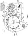
- FIG. 1is a perspective view of a dispenser assembly according to principles of the present disclosure.
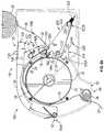
- FIGS. 2A and 2Bare perspective views of the dispenser assembly of FIG. 1 , with a cover assembly in an open position in accordance with the present disclosure.
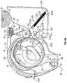
- FIGS. 3A and 3Bare perspective views of the dispenser assembly of FIG. 1 , with a cover assembly in a closed position, and showing portions of the dispenser removed for clarity of illustration in accordance with the present disclosure.
- FIGS. 4A, 4B, and 4Cshow cross-sectional, perspective, and partial views of the cover assembly for the dispenser assembly of FIG. 1 according to principles of the present disclosure.
- FIG. 5is a perspective view of an embodiment of a cover roller for the cover assembly shown in FIGS. 4A-4C .
- FIGS. 6A-Dshow a series of views illustrating an example embodiment of the loading of the dispenser assembly of FIG. 1 according to principles of the present disclosure.
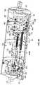
- FIGS. 7A and 7Bshow cross-sectional views of the dispenser assembly of FIG. 1 , with a stub roller transfer assembly in a first position in accordance with the present disclosure.
- FIGS. 8A and 8Bshow cross-sectional views of the dispenser assembly of FIG. 1 , with a stub roller transfer assembly in a second position in accordance with the present disclosure.
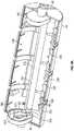
- FIGS. 9A, 9B, and 9Cshow partial views of embodiments of a feed roller for the dispenser assembly of FIG. 1 according to principles of the present disclosure.
- FIGS. 1-9Cshow a dispenser assembly or dispenser 10 for a sheet material, such as for paper towels, tissue paper, other paper products, etc. and/or other suitable sheet materials.
- the dispenser assembly 10has a sheet material loading system or assembly 100 to facilitate loading of supplies sheet material 12 therein, and a sheet material transfer system or mechanism 200 to facilitate the transfer feeding of sheet material between a plurality of supplies of sheet material received within or otherwise along the dispenser assembly 10 .
- the dispenser assembly 10can include a dispenser housing 14 having front 16 , rear 18 , side 20 / 22 , and bottom 24 sides or portions.
- the dispenser housing 14can be formed from a plastic material, though other suitable polymeric, synthetic, or composite materials can be used without departing from the scope of the present disclosure.
- the dispenser assembly 10further at least partially supports and/or includes a plurality of supplies of sheet material, for example, two or more supply rolls of sheet material, including at least a first supply roll 26 and a second supply roll 28 supported within the dispenser housing 14 .
- the supplies 26 / 28 of sheet materialcan include new, un-dispensed rolls of sheet material, or at least partially dispensed rolls of sheet material, e.g., including stub rolls.
- stub rollsmay include rolls with less sheet material than a full roll, and in one embodiment, a stub roll can include a full roll that has been substantially dispensed, e.g., a supply roll with less than about 50% to about 30% or less of its initial/starting amount of sheet material remaining. It also will be understood that, while two supply rolls 26 / 28 are shown in FIGS. 1A-2B , a greater number of supply rolls, such as 3 or more supply rolls, can be used without departing from the scope of the present disclosure.
- the supply rolls 28 and 26are rotatably coupled to the dispenser housing 14 , by opposing supports 30 / 32 ( FIGS. 1 and 3A ).
- the supports 30 / 32can include one or more arms 34 / 36 connected to the dispenser housing 14 , and which can be rotatably coupled to the ends 28 A/B and 26 A/B of the supply rolls 28 / 26 , so that the supply rolls 28 / 26 of sheet material can substantially freely rotate with respect to the arms 34 and 36 as the sheet material is pulled therefrom during dispensing.
- the supply rolls 28 / 26also may be otherwise rotatably or movably mounted to or along the dispenser housing 14 without departing from the scope of the present disclosure.
- the arms 34can be coupled to the rear portion 18 of the dispenser housing 14 ( FIG. 3A ), and the arms 36 can be connected to a backing plate 38 attached to or formed with the rear portion 18 of the dispenser housing 14 ( FIG. 1 ).
- the dispenser assembly 10also generally includes one or more feed rollers 40 rotatably mounted therein.
- the one or more feed rollers 40can be rotatably connected to the dispenser housing 14 .
- the feed roller (or rollers) 40includes a feed roller body 42 , e.g., formed from a plastic material, though other suitable polymeric, synthetic, or composite materials may be used without departing from the scope of the present disclosure.
- the feed roller body 42further can include a plurality of spaced gripping bands 44 (e.g., formed from polymeric or other suitable synthetic or composite materials) applied thereabout.
- the feed roller(s) 40is operable to rotate or pull and guide or feed the sheet material 12 along a feed or discharge path 46 towards a discharge, such as a discharge chute 48 , of the dispenser 10 for dispensing or distribution of an amount or length of the sheet material to a user.
- the discharge chute 48can comprise a discharge opening or slot 50 arranged along the bottom portion 24 of the dispenser housing 14 , as illustrated in FIGS. 3A, 7A and 8A-8B .
- a portion of the sheet material 27 or 29 from the first 26 or second 28 supply rollswill be at least partially disposed about and in engagement or contact with the feed roller 40 , such that, upon rotation of the feed roller 40 the sheet material 27 or 29 from the first 26 or second supply rolls 28 will be pulled, causing the supply rolls 26 / 28 to be rotated and an amount or length of sheet material 12 to thus be fed to and through the discharge chute 48 .
- the feed roller 40can have a diameter selected for feeding a prescribed or predetermined or known length or amount of sheet material.
- the feed roll 40can have a diameter or size selected to feed a 6′′, 8′′, 10′′, 12′′, 14′′, 16′′, etc. (or other integer or non-integer numbers therebetween and/or other suitable predetermined lengths) of sheet material for each revolution or series of revolutions of the feed roller.
- the feed roller 40can be manually driven.
- the dispenser assembly 10can include an engagement portion 52 , such as a lever, knob, or other suitable engagement portion, that is operatively connector to or otherwise in communication with the feed roller 40 , and which engagement portion 52 is configured to be actuated or turned by a user to drive movement/rotation of the feed roller 40 and thus control dispensing of the sheet material. Users further can engage and pull portions of the sheet material hanging from or in (e.g., hanging tabs) the discharge chute 48 for dispensing of sheet material.
- the feed roller 40can be automatically driven by a drive mechanism (e.g., including a motor) that activates when one or more sensors detect a predetermined condition.
- a drive mechanisme.g., including a motor
- a sensorsuch as an infrared sensor or other similar type of sensor, detects the presence of a user's hand in front of, adjacent, or below the dispenser housing 14 , or detects the presence or absence of sheet material extending from the discharge chute 44 .
- U.S. patent application Ser. Nos. 15/173,970, 15/185,776, and 15/185,937which are specifically incorporated by reference herein as if set forth in their entireties, show example arrangements of other drive mechanisms for driving the feed roller.
- any suitable driving mechanism, arrangement, or configurationcan be employed to drive rotation of the feed roller 40 for feeding or dispensing sheet material, without departing from the scope of the present disclosure.
- the drive mechanismfurther can be activated when a user activates the engagement portion or pulls a hanging tab to provide drive assisted dispensing of sheet material.
- FIGS. 1, 2B, and 3A-3Bfurther show that the dispenser assembly 10 can include one or more guide or pressing rollers 54 mounted along or substantially adjacent the discharge 48 .
- Such as guide or pressing roller (or rollers) 54located in a position so as to define a nip and that contact or otherwise engage and direct the sheet material 12 along a feed path toward the discharge chute as the sheet material is fed from the discharge 48 for dispensing from the dispenser 10 .
- the guide roller(s) 54can be biased, such as by one or more springs or other suitable biasing members to contact and engage the sheet material between the guide roller(s) and a portion of the discharge 48 .
- the guide roller(s)can be unbiased, without departing from the scope of the present disclosure.
- the dispenser assembly 10additionally includes a sheet material loading assembly or system 100 as generally shown in FIGS. 1-8B .
- the sheet material loading mechanism/assembly 100can include a cover assembly 102 that is movably connected to the dispenser housing 14 .
- the cover assembly 102includes a cover body 104 that is rotatably or pivotably coupled to the front portion 16 of the dispenser housing 14 , e.g., at a first end 104 A of the cover body 104 , such that the cover body 104 is movable between a closed position 106 and an open position 108 .
- the cover body 104In the closed position 106 , the cover body 104 will at least partially surround and/or at least partially enclose the feed roller 40 , and in the open position 108 , the cover body 104 generally will be substantially spaced away or displaced from the feed roller 40 , e.g., with the cover body extending out and away from the front portion 16 of the dispenser housing 14 .
- the cover body 104has one or more generally arcuate or curved portions or sections that generally follow or conform to the shape of the feed roller 40 , though other shapes or constructions can be employed without departing from the scope of the present disclosure.
- the cover body 104further can be formed from a plastic material, though other polymeric, synthetic, or composite materials are possible in accordance with the present disclosure.
- FIGS. 4A-4Bfurther indicate that the cover body 104 can have sheet material guide or engagement fingers 110 formed with or attached thereto.
- the guide fingers 110can have an elongated body 112 with an engagement portion 114 , such as having a spherical or other suitable shape, at one end thereof and configured to engage the sheet material against the feed roller body 42 , as generally indicated in FIGS. 4A-4B .
- the sheet material loading assembly 100includes one or more locking features or mechanisms 120 configured to lock or secure the cover assembly 102 in its closed position 106 .
- the locking features 120can include switch assemblies 122 having a bracket 124 coupled to the dispenser housing 14 and supporting a biased switch member 126 .
- the biased switch member 126can be biased by a biasing member 128 , such as a spring or other suitable biasing member, so as to be urged towards an extended position to facilitate locking or securing of the cover assembly 102 , and a retracted position that allows for release of the cover assembly 102 in its movement to the open position 108 .
- the switch members 126can engage and hold a portion of the cover body 104 to hold the cover assembly 102 in the closed position 106 , and further can include a tab or engagement portion 130 that will be engaged by an operator to move the switch members 126 along the brackets 124 to their retracted position for release of the cover assembly 102 .
- FIGS. 7A and 8Afurther show the cover assembly 102 to be biased towards its open position 108 , such as by one or more biasing members 132 .
- the biasing members 132can include one or more springs, such as torsion springs, or other suitable biasing members that engage the cover body 104 to bias the cover assembly 102 towards its open position 108 .
- the cover assembly 102With the cover assembly 102 secured in its closed position 106 , the cover assembly 102 can be urged towards its open position 106 by the biasing members 132 .
- the cover assembly 102is moved to its open position upon release or unlocking of the switch members 126 (i.e., when switch members 126 are moved to their retracted position).
- the cover assembly 102includes a cover roller 140 , which can include a guide or pressing roller, connected to the cover body 104 .
- the cover roller 140can be rotatably connected to the cover body 104 at the second end 104 B thereof, and can be biased or urged, e.g., by one or more springs or other biasing members 142 , so as to press or engage at least a portion of the sheet material against the feed roller body 42 , when the cover assembly 102 is in its closed position 106 .
- the cover roller 140can define a nip along the feed roller body 42 .
- the cover assembly 102also includes end bearings or bearing portions 144 that can be connected to or formed with the cover roller 140 , and that support or connected the cover roller 140 to the cover body 104 .
- the bearings 144are received within slots 146 or other openings defined along/in the second end 104 B of the cover body 104 .
- the cover roller 140further is movable along the slots 146 , e.g., under the control/urging of biasing member(s) 142 , which can be coupled to the cover body 104 and can engage the bearings 144 of the cover roller 140 to urge the cover roller 140 towards and into engagement with the feed roller body 42 , e.g., towards a first end 146 A of the slots 146 defined in the cover body 104 .
- the biasing member(s) 142can include a torsion spring 150 with a body 151 having a coiled loop portion 152 , as well as a first and second free ends 154 / 156 .
- the coiled loop portion 152is received about a projection 158 formed along the cover body 104 to couple the torsion spring 150 thereto.
- the first free end 154 of the torsion spring 150can engage a notch or opening 160 in the cover body 104
- the second free end 156 of the torsion spring 150can engage a projecting portion 162 formed with or otherwise connected to the bearing portions 144 of the cover roller 140 .
- the spring 150will urge the bearing portions towards the first end 146 A in the slot 146 and thereby engage the cover roller 140 against the feed roller body 40 , with the cover assembly 102 in its closed position 106 .
- FIGS. 2A-2B, 3A-3B, 4A-4C, and 5also indicate that the cover roller 140 additionally can include one or more sheet material retention portions or features 170 , such as clips, sharpened portions, gripping areas, etc., configured to substantially secure or otherwise couple the sheet material to the cover roller 140 to facilitate loading of the sheet material in the dispenser assembly 10 .
- the cover assembly 102With the cover assembly 102 in its open position 108 , an operator can connect/engage a portion of the sheet material from the first or second supply rolls 26 / 28 of sheet material with the sheet material retention features 170 to secure or otherwise couple the portion of the sheet material 12 about the cover roller 140 .
- the retention features 170can include biased clips 172 that engage the sheet material 12 against the cover roller 140 .
- the clips 172each can include a clip body 174 connected to the cover roller 140 at one end 174 A, such that the clip body 174 is pressed or engaged against an outer surface 176 of the cover roller 140 , and a projecting portion 178 can be engaged by an operator to move the clip body 174 away from the cover roller 140 as needed, such as to allow the sheet material to be inserted and/or positioned between the clip body 174 and the outer surface 176 of the cover roller 140 .
- the clip body 174presses or engages the sheet material against the outer surface 176 of the cover roller 140 to couple the sheet material thereto.
- FIGS. 6A-6Dshow schematic diagrams for loading of the dispenser assembly 10 according to principles of the present disclosure.
- FIGS. 6A-6Bshow that after one of the supply rolls, e.g., supply roll 28 , has been substantially dispensed ( FIG. 6A ), the supply roll can be removed.
- this substantially dispensed supply of sheet materialcan be moved to a stub roll position, e.g., it can be substituted for and/or it can become the first supply roll 26 .
- a stub roll positione.g., it can be substituted for and/or it can become the first supply roll 26 .
- a new, un-dispensed supply rollcan be loaded into the dispenser assembly 10 , into the position of supply roll 28 , and an end portion 180 of the sheet material 29 can be engaged with the retention features 170 to engage the sheet material 29 about/along the cover roller 140 .
- the cover assembly 102can be moved to its closed position 106 , such that the cover roller 140 engages or presses the sheet material against the feed roller body 42 .
- the sheet materialcan be engaged and urged along the discharge path 46 and toward and through the discharge 48 of the dispenser housing 14 . Accordingly, with embodiments of the present disclosure, operators generally do not have to struggle to load the sheet material through tight clearances in the dispenser assembly, as with traditional dispensers.
- FIGS. 7A-8Badditionally show that the dispenser assembly 10 also can include a supply roll transfer assembly or mechanism 200 that facilitates transfer of feeding between the first 26 and second 28 supply rolls.
- the supply roll transfer assembly 200is operatively connected to or is otherwise in operative communication with the cover roller 140 .
- the supply roll transfer assembly 200facilitates and/or allows movement of the cover roller 140 (and sheet material engaged therewith or extending thereabout) toward engagement with the feed roller body 42 to initiate dispensing of the sheet material from another supply of sheet material, e.g., enabling dispensing from the second supply roll 28 when the first supply roll has been substantially exhausted, or from the first supply roll 26 after the second supply roll has been substantially exhausted.
- the transfer assembly 200includes a transfer arm or other portion 202 that is movable between a plurality of feeding positions to facilitate transfer of feeding of sheet material between the first 26 and second 28 supply rolls—e.g., the transfer arm 202 is movable between a first feeding position 204 for feeding sheet material from one supply roll, and a second feeding position 206 for feeding sheet material from another supply roll.
- the transfer arm 202is operatively connected to or otherwise in operative communication with the cover roller 140 .
- the transfer arm 202In the first feeding position 204 , the transfer arm 202 is positioned or configured to substantially maintain the cover roller 140 (and sheet material connected thereto) in a position spaced away from the feed roller body 42 .
- the transfer arm 202In the second feeding position 206 , the transfer arm 202 is positioned or otherwise configured to allow engagement between the cover roller 140 (and sheet material connected thereto) and the feed roller body 42 , i.e., such that sheet material connected to or engaged by the cover roller 140 is pressed against the feed roller body 42 .
- sheet material 27 from the first supply roll 26will be fed with the transfer arm 202 in its first feeding position 204
- sheet material 29 from the second supply roll 28will be fed with the transfer arm 202 in its second feeding position 206 , though these positions can be reversed without departing from the scope of the present disclosure.
- sheet material from the first supply roll 26can be engaged with the feed roller 40
- sheet material from the second supply roll 28can be engaged with the cover roller 140 (e.g., via retention features 170 ).
- transfer arm 202can engage a portion of the cover roller 140 connected to the cover assembly 102 , such that the cover roller 140 (and the sheet material from the second supply roll 28 received thereabout) is positioned substantially apart or substantially spaced away from the feed roller body 42 , e.g., to define a sufficient gap or space 210 between the cover roller 140 and the feed roller body 142 .
- the transfer arm 202can include a projecting portion or flange 208 that engages or presses against the bearing portion 144 of the cover roller 140 to press the bearing portion 144 against or to urge the bearing portion 144 towards the second end 146 B of the slots 146 , with the cover roller 140 spaced away from (i.e., the gap or space 210 between) the feed roller body 42 .
- the cover roller 140can be spaced about 2.5 mm to about 3.5 mm from the feed roller body 42 , though the cover roller 140 can be spaced less than about 2.5 mm or more than about 3.5 mm from the feed roller body 42 without departing from the scope of the present disclosure.
- FIGS. 7A-8Bfurther shows the transfer arm 202 including a guide roller 212 rotatably attached to a first end 202 A of the transfer arm 202 and configured to engage and guide the sheet material 27 from the first supply roll 26 , with the transfer arm 202 in the first position 204 (i.e., when the dispenser assembly 10 is feeding sheet material from the first supply roll 26 ).
- the guide roller 212can engage and direct the sheet material 27 from the first supply roll 26 so that it is engaged and driven by the feed roller body 42 along the discharge path 46 through the discharge 48 .
- the transfer assembly 200additionally includes a fixed support or elongated body 214 positioned along or substantially adjacent to the transfer arm 202 as generally indicated in FIGS. 7A-8B .
- the fixed support 214generally is configured to engage the sheet material from 27 the first supply roll 26 during feeding thereof, such that the sheet material 27 from the first supply roll 26 is engaged between the guide roller 212 and the fixed support 214 holding the transfer arm 202 in its first feeding position 204 ( FIGS. 7A-7B ).
- the transfer arm 202will move to its second position 206 such that cover roller 140 is engaged against the feed roller body 42 to facilitate feeding of the sheet material 29 from the second supply roll 28 . More specifically, movement of the transfer arm to its second feeding position 206 allows the bearing portions 144 of the cover roller 140 to be moved to the first end 146 A of the slots 146 , e.g., under urging or force of the biasing members 142 connected to the cover roller 140 , to facilitate engagement of the sheet material 29 from the first supply roll 26 received about the cover roller 140 against the feed roller body 42 for dispensing thereof.
- the guide roller 212 and the fixed support 214are configured to interact, e.g., the guide roller 212 moves in relation to the fixed support 214 , to facilitate movement of the transfer arm 202 from its first position 204 to its second position 206 .
- the guide roller 212can be configured to intermesh or interleave with the fixed support 214 when/after the sheet material 27 from the first supply roll 26 is dispensed, i.e., there no longer is sheet material 27 engaged between the guide roller 212 and the fixed support 214 .
- the fixed support 214can include a plurality of spaced ribs or portions 214 A with a plurality of spaces 214 B defined therebetween and arranged along a length of the fixed support 214 .
- the guide roller 212also can include a plurality of spaced ribs or portions 212 A defining spaces 212 B therebetween and arranged along a length of the guide roller 212 .
- the spaced portions 212 A of the guide roller 212are configured to align with the spaces 214 B in the fixed support 214
- the spaced portions 214 A in the fixed support 214are configured to align with the spaces 212 B in the guide roller 212 . Accordingly, the spaced portions 214 A of the fixed support 214 and spaced portions 212 A of the guide roller 212 can intermesh or interleave when sheet material is not present therebetween.
- the spaced portions 214 A of the fixed support 214 and spaced portions 212 A of the guide roller 212are positioned into the corresponding spaces 214 B and 212 B of the fixed support 214 and guide roller 212 .
- FIGS. 7A-8Bfurther show that the transfer arm 202 is pivotably or rotatably attached (e.g., at pivoting or rotating connection 220 ) to the dispenser housing 14 at a second end 202 B thereof.
- the transfer arm 202can rotate or pivot to the second feeding position 206 .
- the transfer arm 202can be biased towards its second feeding position 206 , e.g., by one or more biasing members 222 , such as tension springs or other biasing member coupled to the transfer arm 202 .
- the biasing members 222can bias or urge the transfer arm 202 toward a position to engage the sheet material 27 from the first supply roll 26 between the guide roller 212 and fixed support 214 in the dispensing positon 204 , and when the first supply roll 26 is exhausted/substantially dispensed, can bias or urge the transfer arm 202 forward its second feeding position 206 .
- the transfer assembly 200can allow for substantially seamless transfer of feeding of sheet material between the first supply roll 26 and the second supply roll 28 of sheet materials, without requiring refeeding or manual manipulation of the supplies, while also avoiding double sheet dispensing.
- FIGS. 7A, 7B, and 9Ashow a cutting assembly or system 320 that is integrated with the feed roller 40 .
- the cutting assembly 320can include a cutting blade 322 and a base or support 324 connected to and at least partially supporting the cutting blade 322 .
- the base 324can be pivotably or otherwise movably mounted within a cavity or chamber 42 A defined within the feed roller body 42 , such that teeth or sharpened portions 330 of the cutting blade 322 are extensible from the feed roller body, moving between extended and retracted positions out of and back through an opening or slot 332 defined along the feed roller 40 by movement of the base 324 .
- the base 324will have a body 332 that can be formed from a plastic material or other polymeric material, though other suitable materials, such as rubber, wood, composites, etc., also can be used without departing from the scope of the present disclosure.
- the base 324generally will be coupled or connected to the cutting blade 322 along a portion 338 of the base 324 , such as by a series of fasteners, e.g. screws, bolts, rivets, etc., though the cutting blade can be otherwise fixed to or integrated with the support/base, without departing from the scope of the present disclosure.
- the base 324further will be rotatably or pivotally coupled to at least a portion of the feed roller 40 .
- the cutting assembly 320can be connected to the feed roller 40 by a pivoting or rotatable connection 346 , and can move/rotate with rotation of the feed roller 40 during dispensing of the sheet material.
- the cutting assembly 320also can include one or more biasing members, such as torsion springs, or other suitable biasing members, that provide a biasing force against the support/base 324 sufficient to urge or bias the support/base 324 , and thus the cutting blade 322 , toward a retracted position.
- FIGS. 7B and 9Afurther show that the base 324 also can have a cam follower assembly 352 arranged along the top portion 338 thereof.
- the cam follower assembly 352generally will have one or more cam followers 354 , which can include bearings, rollers, or other rotating members, and which are configured to engage and move along one or more corresponding cam surfaces or tracks 366 located within the cavity 42 A of the feed roller body 42 as the feed roller 40 is rotated. As the feed roller rotates, the body will be correspondingly pivoted/rotated to move the cutting blade 322 out from and back into the opening/slot 332 .
- the cutting assembly 320can include a cam track 370 that can be mounted in a substantially fixed or stationary position within the cavity 42 A of the feed roller body 42 , such that the feed roller body 42 and the base 324 are rotated about such cam track 370 , such as indicated in FIGS. 16A-E .
- the cam track 370further can have one or more sections 372 provided therealong that are engaged by the cam followers 350 to cause the base/support 324 to pivot, rotate, or otherwise move and thereby extend the cutting blade 322 out from the opening/slot 332 in the feed roller 40 for at least partial perforation or cutting of the sheet material.
- FIGS. 9B and 9Cfurther show that the feed roller body 42 , in some embodiments, can include a biasing assembly 450 disposed within cavity 42 A and operable to assist rotation of the feed roller body 42 and movement of the cutting assembly 320 , for example, upon manual activation of the feed roller body 42 .
- a biasing assembly 450disposed within cavity 42 A and operable to assist rotation of the feed roller body 42 and movement of the cutting assembly 320 , for example, upon manual activation of the feed roller body 42 .
- An example biasing assemblyis shown and described in U.S. Provisional Patent Application No. 62/741,350, which is specifically incorporated by reference herein as if set forth in its entirety.
- the biasing assembly 450can include one or more biasing members 452 , e.g. in the embodiment illustrated, a pair of biasing members 452 are shown extending along the interior surface 42 B of the feed roller body 42 . It will be understood that fewer or additional biasing elements also can be used, without departing from the scope of the present disclosure.
- Each biasing member 452can comprise a tension spring or other suitable tensioning or biasing member, having an elongated spring body 454 with first and second ends 454 A/B.
- the biasing members 452also generally extend in a direction that is parallel to the longitudinal (or rotational) axis LA (shown in FIG. 9B ) of the feed roller body 328 , and can be fixably attached to the interior surface 42 B of the feed roller body 42 .
- each biasing member 452can engage and couple to a connection mechanism 458 , such as flange, arm, or other connecting member attached to the feed roller body 42 by one or more fasteners, (e.g., a screw, rivet, or other fastener).
- a connection mechanism 458such as flange, arm, or other connecting member attached to the feed roller body 42 by one or more fasteners, (e.g., a screw, rivet, or other fastener).
- the first end 454 A of the spring body 454 of each biasing member 452can include a hoop, ring, hook or other suitable feature or mechanism that connects to a protruding portion 460 formed with, or connected to the connection mechanism 458 , which portion 460 has a notch or opening 460 A for receiving the hoop, ring, or hook of the spring.
- the second end 454 B of each biasing member 452can be similarly attached to a connecting linkage FIG. 9B .
- connection mechanism 458can include a body 462 that is connected to, or engages, portions or protrusions 464 and 466 fixed to, or integrally formed with, the feed roller body 42 .
- the protrusions 464 and 466can be received within openings or apertures defined along body 462 of the connection mechanism, and/or can include threaded openings defined therein to receive fasteners passed through the openings of the body 462 of the connection mechanism to secure the body 462 to the feed roller body 42 .
- the body 462can have a generally Z-shaped cross-section to facilitate connection of the body 462 to the portions 464 / 466 , though the body can have other suitable shapes and configurations, without departing from the scope of the present disclosure.
- the feed roller body 42can have a plurality of attachment points 464 / 466 about interior surface 329 thereof.
- the feed roller body 328can have multiple portions 464 / 466 formed/connected to the feed roller 40 in spaced series to allow for adjustment (e.g., tightening or loosening) of the biasing members 452 , e.g., to accommodate different sheet material sizes and/or to correct for time dependent displacement or movements of the spring due to the repeated loading.
- up to five attachment pointscan be provided, though any suitable number of attachment points, e.g., 2, 3, 4, or more than 5, can be employed without departing from the scope of the present disclosure.
- each linkage 456can include a wire, band, belt, or rod 468 , or other flexible coupling.
- the first end 456 A of each linkage 456can be formed as a looped end, and can be connected to a second end 454 B of a corresponding biasing member 454 such as by a hook, hoop, or split-ring type of connection forming the second end 454 B of the biasing member 454 .
- each linkage 456can be formed with a similar looped end and generally will be rotatably connected to a portion, such as tracks 366 , that does not rotate, e.g., is fixed in relation to, the feed roller, such as by attachment to a fastener 472 (e.g., screw, bolt, etc.) or other suitable connection mechanism.
- the fastener 472also can have one or more spacers 474 received therealong to engage and facilitate alignment of the second looped ends 456 B of the linkages 456 ( FIGS. 9B and 9C ).
- the biasing assembly 450can include one or more pulley assemblies 480 (as shown in FIGS. 9B and 9C ) that engage and facilitate a change in the direction of the linkages 456 operatively connecting the biasing members 452 to the feed roller body 42 .
- Each of the pulley assemblies 480can include a bracket 482 that is connected to the interior surface 329 of the feed roller body 328 and that at least partially supports a pulley 484 having a track or race 486 against which at least a portion of the linkage 456 is engaged and/or moves.
- the pulley brackets 482can be pivotably or rotatably mounted (e.g., by a pinned or hinged connection 488 ) to the interior surface 42 B of the feed roller body 328 .
- the pinned or hinged connection 488can help to maintain engagement between, or substantially prevent misalignment of, the linkage 456 and the pulleys 484 , e.g., as/when the feed roller body 42 is rotated and the biasing assembly 450 is rotated therewith.
- the interior surface 42 B of the feed roller body 42further can have a notch or recessed portion 489 formed/defined therein to accommodate movement/pivoting of the brackets 482 .
- the feed roller body 42rotates and carries the biasing assembly 450 therewith.
- the linkages 456are caused to be pulled or otherwise engaged about the pulleys 484 , tensioning and stretching the spring bodies of the biasing members 452 , thus creating tension in or along the biasing members 452 .
- This tensionassists in the rotation of the feed roller body 40 and helps urge the feed roller body 42 to facilitate return of the feed roller body 40 to a rest or home position.
- the rotation of the feed roller 40can be sufficient to generate a tab or portion for pulling or engagement by subsequent users for dispensing a selected portion of sheet material. Also, this tension helps facilitate rotation of the feed roller body 42 sufficient to cause activation or movement of the cutting blade 322 of the dispenser assembly 10 to cut, perforate, or otherwise cause or assist in separation of a sheet of the sheet material.
- the return movement of the feed roller body 42also can cause retraction of the cutting blade 322 (e.g., into notch, recess in the feed roller body 42 ).
Landscapes
- Health & Medical Sciences (AREA)
- Public Health (AREA)
- Sheets, Magazines, And Separation Thereof (AREA)
Abstract
Description
Claims (22)
Priority Applications (4)
| Application Number | Priority Date | Filing Date | Title |
|---|---|---|---|
| US16/893,516US11478111B2 (en) | 2019-06-14 | 2020-06-05 | Loading and transfer system/assembly for sheet material dispensers |
| US17/968,421US11864695B2 (en) | 2019-06-14 | 2022-10-18 | Loading and transfer system/assembly for sheet material dispensers |
| US18/242,721US12161269B2 (en) | 2019-06-14 | 2023-09-06 | Loading and transfer system/assembly for sheet material dispensers |
| US18/932,001US20250049270A1 (en) | 2019-06-14 | 2024-10-30 | Loading and transfer system/assembly for sheet material dispensers |
Applications Claiming Priority (2)
| Application Number | Priority Date | Filing Date | Title |
|---|---|---|---|
| US201962861425P | 2019-06-14 | 2019-06-14 | |
| US16/893,516US11478111B2 (en) | 2019-06-14 | 2020-06-05 | Loading and transfer system/assembly for sheet material dispensers |
Related Child Applications (1)
| Application Number | Title | Priority Date | Filing Date |
|---|---|---|---|
| US17/968,421ContinuationUS11864695B2 (en) | 2019-06-14 | 2022-10-18 | Loading and transfer system/assembly for sheet material dispensers |
Publications (2)
| Publication Number | Publication Date |
|---|---|
| US20200390295A1 US20200390295A1 (en) | 2020-12-17 |
| US11478111B2true US11478111B2 (en) | 2022-10-25 |
Family
ID=73745781
Family Applications (4)
| Application Number | Title | Priority Date | Filing Date |
|---|---|---|---|
| US16/893,516Active2040-10-21US11478111B2 (en) | 2019-06-14 | 2020-06-05 | Loading and transfer system/assembly for sheet material dispensers |
| US17/968,421ActiveUS11864695B2 (en) | 2019-06-14 | 2022-10-18 | Loading and transfer system/assembly for sheet material dispensers |
| US18/242,721ActiveUS12161269B2 (en) | 2019-06-14 | 2023-09-06 | Loading and transfer system/assembly for sheet material dispensers |
| US18/932,001PendingUS20250049270A1 (en) | 2019-06-14 | 2024-10-30 | Loading and transfer system/assembly for sheet material dispensers |
Family Applications After (3)
| Application Number | Title | Priority Date | Filing Date |
|---|---|---|---|
| US17/968,421ActiveUS11864695B2 (en) | 2019-06-14 | 2022-10-18 | Loading and transfer system/assembly for sheet material dispensers |
| US18/242,721ActiveUS12161269B2 (en) | 2019-06-14 | 2023-09-06 | Loading and transfer system/assembly for sheet material dispensers |
| US18/932,001PendingUS20250049270A1 (en) | 2019-06-14 | 2024-10-30 | Loading and transfer system/assembly for sheet material dispensers |
Country Status (4)
| Country | Link |
|---|---|
| US (4) | US11478111B2 (en) |
| EP (1) | EP3982803A4 (en) |
| CA (1) | CA3142926A1 (en) |
| WO (1) | WO2020251841A1 (en) |
Cited By (6)
| Publication number | Priority date | Publication date | Assignee | Title |
|---|---|---|---|---|
| US20230064043A1 (en)* | 2019-06-14 | 2023-03-02 | Valve Solutions, Inc. | Loading and transfer system/assembly for sheet material dispensers |
| US12024380B2 (en) | 2018-12-12 | 2024-07-02 | Charles Agnew Osborne, Jr. | Dispensing assembly for selectively dispensing a plurality of supplies of rolled sheet material |
| US20240292982A1 (en)* | 2021-04-27 | 2024-09-05 | Kimberly-Clark Worldwide, Inc. | Dispenser with Roll Transfer Mechanism |
| US12114812B2 (en) | 2019-01-02 | 2024-10-15 | Valve Solutions, Inc. | Dispensing and monitoring systems and methods |
| US20240415336A1 (en)* | 2022-01-14 | 2024-12-19 | Kimberly-Clark Worldwide, Inc. | A Variable Speed Dispenser |
| US12329327B2 (en) | 2022-02-08 | 2025-06-17 | Vsi Health And Hygiene Group, Llc | Sheet material dispenser assembly for selectively dispensing sheet material from a plurality of supplies of rolled sheet material |
Families Citing this family (4)
| Publication number | Priority date | Publication date | Assignee | Title |
|---|---|---|---|---|
| US11154166B2 (en) | 2018-05-24 | 2021-10-26 | Charles Agnew Osborne, Jr. | Dispenser for rolled sheet materials |
| US12268341B2 (en) | 2018-05-24 | 2025-04-08 | Charles Agnew Osborne, Jr. | Sheet material dispensing assembly with integrated gear clutch |
| EP3801164B1 (en) | 2018-05-24 | 2025-05-14 | Charles Agnew Osborne, Jr. | Dispenser for rolled sheet materials |
| US11246460B2 (en) | 2018-11-28 | 2022-02-15 | Charles Agnew Osborne, Jr. | Sheet material dispenser assembly for selectively dispensing sheet material from a plurality of supplies of rolled sheet material |
Citations (110)
| Publication number | Priority date | Publication date | Assignee | Title |
|---|---|---|---|---|
| US2930663A (en) | 1955-01-19 | 1960-03-29 | Raymond L Weiss | Towel dispenser |
| US3017131A (en) | 1958-06-23 | 1962-01-16 | Philip A Wooster | Paper towel dispenser |
| US3269592A (en) | 1963-09-26 | 1966-08-30 | Alwin Mfg Company | Universal towel dispenser |
| US3288387A (en) | 1964-12-08 | 1966-11-29 | Jr William J Craven | Paper towel dispenser |
| US3628743A (en) | 1969-11-04 | 1971-12-21 | Scott Paper Co | Dispensing cabinet for sheet material |
| US3730409A (en)* | 1970-03-28 | 1973-05-01 | Steiner Co Lausanne Sa | Dispensing apparatus |
| US3843218A (en) | 1973-03-06 | 1974-10-22 | Alwin Mfg Co Inc | Roll towel dispenser |
| US3858951A (en) | 1972-03-29 | 1975-01-07 | Georgia Pacific Corp | Towel dispenser |
| US3917191A (en) | 1972-04-12 | 1975-11-04 | Fort Howard Paper Co | Paper towel dispenser and transfer mechanism |
| US4010909A (en) | 1975-09-15 | 1977-03-08 | Scott Paper Company | Dispensing cabinet for sheet material |
| US4067509A (en) | 1973-08-27 | 1978-01-10 | Fort Howard Paper Company | Paper towel dispenser and transfer mechanism |
| US4165138A (en) | 1976-11-15 | 1979-08-21 | Mosinee Paper Company | Dispenser cabinet for sheet material and transfer mechanism |
| US4317547A (en) | 1980-07-07 | 1982-03-02 | Fleck Industries, Inc. | Transfer paper towel dispenser |
| US4358169A (en) | 1980-07-25 | 1982-11-09 | Griffith-Hope Company | Dispenser for coiled sheet material |
| US4378912A (en) | 1981-11-12 | 1983-04-05 | Crown Zellerbach Corporation | Sheet material dispenser apparatus |
| US4403748A (en) | 1981-08-27 | 1983-09-13 | Griffith-Hope Company | Dispenser for coiled material having improved transfer mechanism |
| US4712461A (en) | 1985-10-18 | 1987-12-15 | Georgia-Pacific Corporation | Rolled material dispenser with feed roller containing a sliding cutter |
| EP0317448A1 (en) | 1987-11-20 | 1989-05-24 | Maurice Granger | Control device for the cutting plate of a distribution device, and for simultaneously cutting wound strip |
| US5131302A (en) | 1989-02-23 | 1992-07-21 | Yukinobu Watanabe | Automatic toilet paper supplier |
| US5375785A (en) | 1992-12-02 | 1994-12-27 | Georgia-Pacific Corporation | Automatic web transfer mechanism for flexible sheet dispenser |
| US5400982A (en) | 1992-05-28 | 1995-03-28 | Fort Howard Corporation | Dispenser for multiple rolls of sheet material |
| US5452832A (en)* | 1993-04-06 | 1995-09-26 | Qts S.R.L. | Automatic dispenser for paper towels severable from a continuous roll |
| US5558302A (en) | 1995-02-07 | 1996-09-24 | Georgia-Pacific Corporation | Flexible sheet material dispenser with automatic roll transferring mechanism |
| US5604992A (en) | 1995-01-18 | 1997-02-25 | Robinson; Joe M. | Dual roll dispenser |
| US5620128A (en) | 1995-02-17 | 1997-04-15 | Robert K. Dingman | Dispenser for rolled sheet material |
| US5857393A (en) | 1996-06-28 | 1999-01-12 | Kohiyama; Yuko | Automatic paper feeding apparatus |
| US5924617A (en)* | 1996-08-29 | 1999-07-20 | Alwin Manufacturing Co., Inc. | Multiple roll towel dispenser |
| US6145779A (en) | 1999-09-23 | 2000-11-14 | Kimberly-Clark Worldwide, Inc. | Dual roll transfer dispenser |
| US6152397A (en) | 1998-10-30 | 2000-11-28 | Kimberly-Clark Worldwide Inc. | Spacing member for a sheet material dispenser |
| EP1097665A2 (en) | 1999-11-08 | 2001-05-09 | Georgia-Pacific Corporation | Web transfer mechanism for flexible sheet dispenser |
| US6321963B1 (en) | 1998-02-02 | 2001-11-27 | Fort James Corporation | Sheet material dispensing apparatus and method |
| WO2002000083A1 (en) | 2000-06-28 | 2002-01-03 | Georgia-Pacific Corporation | Paper towel dispenser with powered transfer mechanism |
| US6354533B1 (en) | 1999-08-25 | 2002-03-12 | Georgia-Pacific Corporation | Web transfer mechanism for flexible sheet dispenser |
| US20020073821A1 (en) | 2000-12-15 | 2002-06-20 | Broehl Joshua M. | Sheet material dispenser with transfer system and method |
| US20020109036A1 (en) | 2001-02-09 | 2002-08-15 | Denen Dennis Joseph | Minimizing paper waste carousel-style dispenser apparatus, sensor, method and system with proximity sensor |
| US6460798B1 (en) | 2000-10-10 | 2002-10-08 | Alwin Manufacturing Co., Inc. | Dispenser apparatus with transfer mechanism |
| EP1321084A1 (en) | 2001-12-20 | 2003-06-25 | Fort James Corporation | Support sled for rolls of absorbent sheet and dispenser incorporating same |
| US20030168489A1 (en) | 2002-03-07 | 2003-09-11 | Georgia-Pacific Corporation | Apparatus and methods usable in connection with dispensing flexible sheet material from a roll |
| US6648267B2 (en) | 2000-03-09 | 2003-11-18 | Bay West Paper Corporation | Double core tissue roll, dispenser and method |
| US20040004152A1 (en) | 2002-07-03 | 2004-01-08 | Kapiloff David W. | Dispenser for multiple rolls of sheet material |
| US20040004153A1 (en) | 2002-07-03 | 2004-01-08 | Kapiloff David W. | Dispenser for multiple rolls of sheet material |
| US20040134924A1 (en) | 2002-06-03 | 2004-07-15 | Alwin Manufacturing Co., Inc. | Automatic dispenser apparatus |
| US20040160234A1 (en) | 2001-02-09 | 2004-08-19 | Georgia-Pacific Corporation | Proximity detection circuit and method of detecting capacitance changes |
| US20040178297A1 (en) | 2001-02-09 | 2004-09-16 | Georgia-Pacific Corporation | Static build-up control in dispensing system |
| US6902134B2 (en)* | 2002-09-12 | 2005-06-07 | Kimberly-Clark Worldwide, Inc. | Dispenser for rolled paper |
| US20050167541A1 (en) | 2004-01-30 | 2005-08-04 | Osborne Charles A. | Intelligent dispensing system |
| EP1232715B1 (en) | 2001-02-09 | 2005-11-23 | Georgia-Pacific Corporation | Paper towel dispenser |
| US20060034649A1 (en) | 2004-08-16 | 2006-02-16 | Samsung Electronics Co., Ltd. | Paper transfer unit and image forming apparatus employing the same |
| US7083138B2 (en) | 2004-01-29 | 2006-08-01 | Bay West Paper Corporation | Two roll paper web material dispenser |
| US7185841B2 (en)* | 2001-12-07 | 2007-03-06 | Werner Kaufmann | Hygienic paper dispenser |
| US7296765B2 (en) | 2004-11-29 | 2007-11-20 | Alwin Manufacturing Co., Inc. | Automatic dispensers |
| WO2008004919A1 (en) | 2006-07-07 | 2008-01-10 | Sca Hygiene Products Ab | Dispenser for products in sheet form |
| US20080099595A1 (en) | 2006-10-30 | 2008-05-01 | Kimberly-Clark Worldwide, Inc. | System and method for dissipating static electricity in an electronic sheet material dispenser |
| US7380748B2 (en) | 2004-12-14 | 2008-06-03 | Georgia-Pacific Consumer Products Lp | Towel dispenser with improved drive roll and improved dispensing chute |
| US20080245922A1 (en) | 2007-04-09 | 2008-10-09 | Fellhoelter Scott T | Automatic multi-roll touch-less toilet paper dispenser |
| US7793882B2 (en) | 2006-02-18 | 2010-09-14 | Georgia-Pacific Consumer Products Lp | Electronic dispenser for dispensing sheet products |
| JP2010233971A (en) | 2009-03-31 | 2010-10-21 | Daio Paper Corp | Roll paper dispenser |
| CA2760805A1 (en) | 2009-05-08 | 2010-11-11 | Georgia-Pacific Consumer Products Lp | Sheet product dispenser |
| US20100286818A1 (en) | 2009-05-08 | 2010-11-11 | Georgia-Pacific Consumer Products Lp | Sheet product dispenser with sensor for sheet separation |
| US7832678B2 (en) | 2006-07-07 | 2010-11-16 | Sca Hygiene Products Ab | Dispenser for rolls |
| US7887005B2 (en)* | 2007-09-12 | 2011-02-15 | Innovia Intellectual Properties, Llc | Easy-load household automatic paper towel dispenser |
| US7963475B2 (en) | 2005-12-08 | 2011-06-21 | Alwin Manufacturing Co., Inc. | Method and apparatus for controlling a dispenser and detecting a user |
| US7967235B2 (en) | 2006-10-03 | 2011-06-28 | Sca Tissue North America Llc | Dispenser that automatically transfers rolls of absorbent material, method of reloading same, and rolls of absorbent material for use in same |
| US7987756B2 (en) | 2007-12-03 | 2011-08-02 | Kimberly-Clark Worldwide Inc. | Electro-manual dispenser |
| EP2377442A1 (en) | 2006-10-03 | 2011-10-19 | Georgia-Pacific Consumer Products LP | Automated tissue dispenser |
| US8231076B2 (en)* | 2009-06-06 | 2012-07-31 | Innovia Intellectual Properties, Llc | Dispenser with toweling received within recess of loading door |
| US20120312853A1 (en) | 2011-06-08 | 2012-12-13 | Osborne Charles A | Electronic dispenser for flexible rolled sheet material |
| US8418950B2 (en) | 2008-05-05 | 2013-04-16 | Hans Georg Hagleitner | Paper dispenser |
| US8439293B2 (en) | 2008-05-05 | 2013-05-14 | Hans Georg Hagleitner | Paper dispenser |
| US8448890B2 (en) | 2008-05-05 | 2013-05-28 | Hans Georg Hagleitner | Paper dispenser |
| US8464976B2 (en)* | 2005-12-14 | 2013-06-18 | Sca Hygiene Products Ab | Dispenser loading arrangement and method of loading a dispenser |
| US20130320130A1 (en) | 2010-12-03 | 2013-12-05 | Charles Agnew Osborne, Jr. | Carriage assembly for sequential paper products dispensers |
| US8800415B2 (en) | 2011-04-06 | 2014-08-12 | Solaris Paper, Inc. | Transfer mechanism for sheet material dispenser |
| US20140263812A1 (en) | 2013-03-15 | 2014-09-18 | Charles A. Osborne | Electronic residential tissue dispenser |
| US20140367507A1 (en) | 2013-06-13 | 2014-12-18 | Dispensing Dynamics International | Dispensing system for consecutively dispensing paper sheet material from a stub roll and a primary roll |
| US8919688B2 (en) | 2006-10-03 | 2014-12-30 | Georgia-Pacific Consumer Products Lp | Automated sheet product dispenser |
| US20150157177A1 (en) | 2013-11-04 | 2015-06-11 | Wausau Paper Towel & Tissue, Llc | Dual roll paper towel dispenser |
| US20150297043A1 (en) | 2014-04-18 | 2015-10-22 | Vsi Import Solutions, Llc | Electronic residential tissue dispenser |
| US20150327735A1 (en) | 2012-12-20 | 2015-11-19 | Sca Hygiene Products Ab | Dispenser |
| US20150342423A1 (en) | 2012-07-02 | 2015-12-03 | Sca Hygiene Products Ab | Dispenser |
| US9370283B2 (en) | 2006-02-06 | 2016-06-21 | Scott Fellhoelter | Paper product dispenser |
| WO2016100462A1 (en) | 2014-12-19 | 2016-06-23 | Georgia-Pacific Consumer Products Lp | Automatic napkin dispenser |
| US20160347567A1 (en) | 2015-05-25 | 2016-12-01 | Riso Kagaku Corporation | Paper transfer device |
| US20160353946A1 (en) | 2015-06-04 | 2016-12-08 | Charles Agnew Osborne, Jr. | Electronic dispenser for flexible rolled sheet material |
| US20160353947A1 (en) | 2015-06-04 | 2016-12-08 | Charles Agnew Osborne, Jr. | Dispenser for rolled sheet materials with motorized spindle |
| US20160353945A1 (en) | 2015-06-04 | 2016-12-08 | Charles Agnew Osborne, Jr. | Dispenser for rolled sheet materials with cutting system |
| US20170055787A1 (en) | 2015-08-31 | 2017-03-02 | Georgia-Pacific Consumer Products Lp | Sheet product dispensers with reduced sheet product accumulation and related methods |
| US20170057775A1 (en) | 2015-08-28 | 2017-03-02 | Georgia-Pacific Consumer Products Lp | Sheet Product Dispenser With Product Level Gauge System |
| US20170074388A1 (en) | 2015-09-14 | 2017-03-16 | Georgia-Pacific Consumer Products Lp | Automated product dispensers and related methods for isolating a drive assembly to inhibit vibration transmission |
| US9604811B2 (en) | 2013-10-01 | 2017-03-28 | Georgia-Pacific Consumer Products Lp | Automatic paper product dispenser with data collection and method |
| US20170112336A1 (en) | 2012-11-30 | 2017-04-27 | Georgia-Pacific Consumer Products Lp | System and method for reducing waste using a sheet product dispenser |
| US20170112335A1 (en) | 2015-10-23 | 2017-04-27 | Georgia-Pacific Consumer Products Lp | Power consumption management methods and systems for product dispensers |
| US9645561B2 (en) | 2015-01-23 | 2017-05-09 | Georgia-Pacific Consumer Products Lp | Optimizing a dispensing parameter of a product dispenser based on product usage data |
| US20170188759A1 (en) | 2015-12-30 | 2017-07-06 | Georgia-Pacific Consumer Products Lp | Hands-free sheet product dispensers and related methods |
| US20170188760A1 (en) | 2016-01-06 | 2017-07-06 | Wausau Paper Towel & Tissue, Llc | Dispenser |
| US9701508B2 (en) | 2015-02-06 | 2017-07-11 | Georgia-Pacific Consumer Products Lp | Hybrid dispenser systems |
| US20170209006A1 (en) | 2016-01-26 | 2017-07-27 | Georgia-Pacific Consumer Products Lp | Mechanical dispenser for perforated sheet products |
| US20170251884A1 (en) | 2016-03-04 | 2017-09-07 | Georgia-Pacific Consumer Products Lp | Dispenser with stroke adjustment capabilities |
| US20170290473A1 (en) | 2016-04-11 | 2017-10-12 | Georgia-Pacific Consumer Products Lp | Sheet product dispenser |
| US9918598B2 (en) | 2011-04-06 | 2018-03-20 | Solaris Paper, Inc. | Side-by-side tissue dispenser door restriction mechanism |
| US20180110380A1 (en) | 2010-11-03 | 2018-04-26 | Solaris Paper, Inc. | Adapter for recessed paper product dispensers |
| US20180170703A1 (en) | 2016-12-20 | 2018-06-21 | Charles Agnew Osborne, Jr. | Cutting system for a dispenser |
| US20180263435A1 (en) | 2017-03-17 | 2018-09-20 | Charles A. Osborne, JR. | Monitoring System for Dispenser |
| US20180263433A1 (en) | 2015-06-04 | 2018-09-20 | Charles Agnew Osborne, Jr. | Dispenser for Rolled Sheet Materials |
| US20190216270A1 (en) | 2018-01-15 | 2019-07-18 | Charles Agnew Osborne, Jr. | Dispenser for Rolled Sheet Materials with Belt Drive System |
| US20190307299A1 (en) | 2018-04-09 | 2019-10-10 | Charles A. Osborne, JR. | Sheet material transfer system/assembly for a dispenser |
| US20200029751A1 (en) | 2018-05-24 | 2020-01-30 | Charles Agnew Osborne, Jr. | Dispenser for rolled sheet materials |
| US10602887B2 (en)* | 2013-08-23 | 2020-03-31 | Gpcp Ip Holdings Llc | Towel dispensers |
| US20200163498A1 (en) | 2018-11-28 | 2020-05-28 | Charles Agnew Osborne, Jr. | Sheet material dispenser assembly for selectively dispensing sheet material from a plurality of supplies of rolled sheet material |
| US11051665B2 (en)* | 2017-10-06 | 2021-07-06 | Chin Chen Jay Co., Ltd. | Rolled sheet material dispenser |
Family Cites Families (7)
| Publication number | Priority date | Publication date | Assignee | Title |
|---|---|---|---|---|
| IT1278153B1 (en)* | 1995-01-04 | 1997-11-17 | Cristian Pattarozzi | PAPER STICK DISTRIBUTOR |
| US6581500B1 (en) | 1997-10-21 | 2003-06-24 | Englewood Ventures Inc. | Paper towel dispensing apparatus |
| EP2760773A4 (en)* | 2011-09-26 | 2015-03-04 | Cascades Canada Ulc | Rolled product dispenser with multiple cutting blades and cutter assembly for a rolled product dispenser |
| WO2020123491A1 (en) | 2018-12-12 | 2020-06-18 | Osborne Charles Agnew Jr | Dispensing assembly for selectively dispensing a plurality of supplies of rolled sheet material |
| CA3124998A1 (en) | 2019-01-02 | 2020-07-09 | Charles Agnew Osborne, Jr. | Power management system for dispensers |
| CA3142926A1 (en)* | 2019-06-14 | 2020-12-17 | Charles Agnew Osborne, Jr. | Loading and transfer system/assembly for sheet material dispensers |
| EP4476154A1 (en) | 2022-02-08 | 2024-12-18 | Valve Solutions, Inc. | A sheet material dispenser assembly for selectively dispensing sheet material from a plurality of supplies of rolled sheet material |
- 2020
- 2020-06-05CACA3142926Apatent/CA3142926A1/enactivePending
- 2020-06-05USUS16/893,516patent/US11478111B2/enactiveActive
- 2020-06-05WOPCT/US2020/036257patent/WO2020251841A1/ennot_activeCeased
- 2020-06-05EPEP20822779.3Apatent/EP3982803A4/enactivePending
- 2022
- 2022-10-18USUS17/968,421patent/US11864695B2/enactiveActive
- 2023
- 2023-09-06USUS18/242,721patent/US12161269B2/enactiveActive
- 2024
- 2024-10-30USUS18/932,001patent/US20250049270A1/enactivePending
Patent Citations (189)
| Publication number | Priority date | Publication date | Assignee | Title |
|---|---|---|---|---|
| US2930663A (en) | 1955-01-19 | 1960-03-29 | Raymond L Weiss | Towel dispenser |
| US3017131A (en) | 1958-06-23 | 1962-01-16 | Philip A Wooster | Paper towel dispenser |
| US3269592A (en) | 1963-09-26 | 1966-08-30 | Alwin Mfg Company | Universal towel dispenser |
| US3288387A (en) | 1964-12-08 | 1966-11-29 | Jr William J Craven | Paper towel dispenser |
| US3628743A (en) | 1969-11-04 | 1971-12-21 | Scott Paper Co | Dispensing cabinet for sheet material |
| US3730409A (en)* | 1970-03-28 | 1973-05-01 | Steiner Co Lausanne Sa | Dispensing apparatus |
| US3858951A (en) | 1972-03-29 | 1975-01-07 | Georgia Pacific Corp | Towel dispenser |
| US3917191A (en) | 1972-04-12 | 1975-11-04 | Fort Howard Paper Co | Paper towel dispenser and transfer mechanism |
| US3843218A (en) | 1973-03-06 | 1974-10-22 | Alwin Mfg Co Inc | Roll towel dispenser |
| US4067509A (en) | 1973-08-27 | 1978-01-10 | Fort Howard Paper Company | Paper towel dispenser and transfer mechanism |
| US4010909A (en) | 1975-09-15 | 1977-03-08 | Scott Paper Company | Dispensing cabinet for sheet material |
| US4165138A (en) | 1976-11-15 | 1979-08-21 | Mosinee Paper Company | Dispenser cabinet for sheet material and transfer mechanism |
| US4317547A (en) | 1980-07-07 | 1982-03-02 | Fleck Industries, Inc. | Transfer paper towel dispenser |
| US4358169A (en) | 1980-07-25 | 1982-11-09 | Griffith-Hope Company | Dispenser for coiled sheet material |
| US4403748A (en) | 1981-08-27 | 1983-09-13 | Griffith-Hope Company | Dispenser for coiled material having improved transfer mechanism |
| US4378912A (en) | 1981-11-12 | 1983-04-05 | Crown Zellerbach Corporation | Sheet material dispenser apparatus |
| US4712461A (en) | 1985-10-18 | 1987-12-15 | Georgia-Pacific Corporation | Rolled material dispenser with feed roller containing a sliding cutter |
| EP0317448A1 (en) | 1987-11-20 | 1989-05-24 | Maurice Granger | Control device for the cutting plate of a distribution device, and for simultaneously cutting wound strip |
| US5131302A (en) | 1989-02-23 | 1992-07-21 | Yukinobu Watanabe | Automatic toilet paper supplier |
| US5400982A (en) | 1992-05-28 | 1995-03-28 | Fort Howard Corporation | Dispenser for multiple rolls of sheet material |
| US5526973A (en) | 1992-12-02 | 1996-06-18 | Georgia-Pacific Corporation | Automatic web transfer mechanism for flexible sheet dispenser |
| US5375785A (en) | 1992-12-02 | 1994-12-27 | Georgia-Pacific Corporation | Automatic web transfer mechanism for flexible sheet dispenser |
| US5452832A (en)* | 1993-04-06 | 1995-09-26 | Qts S.R.L. | Automatic dispenser for paper towels severable from a continuous roll |
| US5604992A (en) | 1995-01-18 | 1997-02-25 | Robinson; Joe M. | Dual roll dispenser |
| US5558302A (en) | 1995-02-07 | 1996-09-24 | Georgia-Pacific Corporation | Flexible sheet material dispenser with automatic roll transferring mechanism |
| US5620128A (en) | 1995-02-17 | 1997-04-15 | Robert K. Dingman | Dispenser for rolled sheet material |
| US5857393A (en) | 1996-06-28 | 1999-01-12 | Kohiyama; Yuko | Automatic paper feeding apparatus |
| US5924617A (en)* | 1996-08-29 | 1999-07-20 | Alwin Manufacturing Co., Inc. | Multiple roll towel dispenser |
| US5979821A (en) | 1996-08-29 | 1999-11-09 | Alwin Manufacturing Co. | Multiple roll towel dispenser |
| US6412678B2 (en) | 1998-02-02 | 2002-07-02 | Fort James Corporation | Sheet material dispensing apparatus and method |
| US6321963B1 (en) | 1998-02-02 | 2001-11-27 | Fort James Corporation | Sheet material dispensing apparatus and method |
| US6685074B2 (en) | 1998-02-02 | 2004-02-03 | Fort James Corporation | Sheet material dispensing apparatus and method |
| US6152397A (en) | 1998-10-30 | 2000-11-28 | Kimberly-Clark Worldwide Inc. | Spacing member for a sheet material dispenser |
| US6354533B1 (en) | 1999-08-25 | 2002-03-12 | Georgia-Pacific Corporation | Web transfer mechanism for flexible sheet dispenser |
| US6145779A (en) | 1999-09-23 | 2000-11-14 | Kimberly-Clark Worldwide, Inc. | Dual roll transfer dispenser |
| EP1097665A3 (en) | 1999-11-08 | 2003-01-02 | Georgia-Pacific Corporation | Web transfer mechanism for flexible sheet dispenser |
| EP1097665A2 (en) | 1999-11-08 | 2001-05-09 | Georgia-Pacific Corporation | Web transfer mechanism for flexible sheet dispenser |
| US7270292B2 (en) | 1999-11-08 | 2007-09-18 | Georgia-Pacific Consumer Operations Llc | Web transfer mechanism for flexible sheet dispenser |
| US20050056721A1 (en) | 1999-11-08 | 2005-03-17 | Georgia-Pacific Corporation | Web transfer mechanism for flexible sheet dispenser |
| US6826991B1 (en) | 1999-11-08 | 2004-12-07 | Georgia-Pacific Corporation | Web transfer mechanism for flexible sheet dispenser |
| US6648267B2 (en) | 2000-03-09 | 2003-11-18 | Bay West Paper Corporation | Double core tissue roll, dispenser and method |
| WO2002000083A1 (en) | 2000-06-28 | 2002-01-03 | Georgia-Pacific Corporation | Paper towel dispenser with powered transfer mechanism |
| US6736348B1 (en) | 2000-06-28 | 2004-05-18 | Georgia-Pacific Corporation | Power transfer system apparatus |
| US6460798B1 (en) | 2000-10-10 | 2002-10-08 | Alwin Manufacturing Co., Inc. | Dispenser apparatus with transfer mechanism |
| US20020073821A1 (en) | 2000-12-15 | 2002-06-20 | Broehl Joshua M. | Sheet material dispenser with transfer system and method |
| US7168602B2 (en) | 2000-12-15 | 2007-01-30 | Georgia-Pacific Corporation | Sheet material dispenser with transfer system and method |
| US6826985B2 (en) | 2000-12-15 | 2004-12-07 | Georgia-Pacific Corporation | Method of dispensing sheet material |
| US6838887B2 (en) | 2001-02-09 | 2005-01-04 | Georgia-Pacific Corporation | Proximity detection circuit and method of detecting small capacitance changes |
| US7017856B2 (en) | 2001-02-09 | 2006-03-28 | Georgia-Pacific Corporation | Static build-up control in dispensing system |
| US20170258278A1 (en) | 2001-02-09 | 2017-09-14 | Georgia-Pacific Consumer Products Lp | Electronically controlled dispenser for dispensing flexible sheet material |
| US20020109036A1 (en) | 2001-02-09 | 2002-08-15 | Denen Dennis Joseph | Minimizing paper waste carousel-style dispenser apparatus, sensor, method and system with proximity sensor |
| US20040160234A1 (en) | 2001-02-09 | 2004-08-19 | Georgia-Pacific Corporation | Proximity detection circuit and method of detecting capacitance changes |
| US20040178297A1 (en) | 2001-02-09 | 2004-09-16 | Georgia-Pacific Corporation | Static build-up control in dispensing system |
| US6793170B2 (en) | 2001-02-09 | 2004-09-21 | Georgia-Pacific Corporation | Waste minimizing paper dispenser |
| US9661958B2 (en) | 2001-02-09 | 2017-05-30 | Georgia-Pacific Consumer Products Lp | Electronically controlled dispenser for dispensing flexible sheet material |
| US7182289B2 (en) | 2001-02-09 | 2007-02-27 | Georgia-Pacific Corporation | Static build-up control in dispensing system |
| US7182288B2 (en) | 2001-02-09 | 2007-02-27 | Georgia-Pacific Corporation | Waste minimizing carousel-style dispenser |
| EP2846466A2 (en) | 2001-02-09 | 2015-03-11 | Georgia-Pacific Consumer Products LP | Dispenser with grounding means and method therefor |
| US6592067B2 (en) | 2001-02-09 | 2003-07-15 | Georgia-Pacific Corporation | Minimizing paper waste carousel-style dispenser apparatus, sensor, method and system with proximity sensor |
| US6871815B2 (en) | 2001-02-09 | 2005-03-29 | Georgia-Pacific Corporation | Static build up control in electronic dispensing systems |
| US20050072874A1 (en) | 2001-02-09 | 2005-04-07 | Georgia-Pacific Corporation | Paper dispenser with proximity detector |
| EP1716800A2 (en) | 2001-02-09 | 2006-11-02 | Georgia-Pacific Corporation | Dispenser with grounding means and method therfor |
| US20050127232A1 (en) | 2001-02-09 | 2005-06-16 | Georgia-Pacific Corporation | Static build-up control in dispensing system |
| EP2846466A3 (en) | 2001-02-09 | 2015-06-17 | Georgia-Pacific Consumer Products LP | Dispenser with grounding means and method therefor |
| EP1232715B1 (en) | 2001-02-09 | 2005-11-23 | Georgia-Pacific Corporation | Paper towel dispenser |
| US7185841B2 (en)* | 2001-12-07 | 2007-03-06 | Werner Kaufmann | Hygienic paper dispenser |
| EP1321084A1 (en) | 2001-12-20 | 2003-06-25 | Fort James Corporation | Support sled for rolls of absorbent sheet and dispenser incorporating same |
| US7237744B2 (en) | 2002-03-07 | 2007-07-03 | Georgia-Pacific Consumer Operations Llc | Apparatus and methods usable in connection with dispensing flexible sheet material from a roll |
| US7624664B2 (en) | 2002-03-07 | 2009-12-01 | Georgia-Pacific Consumer Products Lp | Apparatus and methods usable in connection with dispensing flexible sheet material from a roll |
| US7698980B2 (en) | 2002-03-07 | 2010-04-20 | Georgia-Pacific Consumer Products Llp | Sheet material dispenser |
| US20030168489A1 (en) | 2002-03-07 | 2003-09-11 | Georgia-Pacific Corporation | Apparatus and methods usable in connection with dispensing flexible sheet material from a roll |
| US6830210B2 (en) | 2002-03-07 | 2004-12-14 | Georgia-Pacific Corporation | Apparatus and methods usable in connection with dispensing flexible sheet material from a roll |
| US20030168550A1 (en) | 2002-03-07 | 2003-09-11 | Georgia-Pacific Corporation | Apparatus and methods usable in connection with dispensing flexible sheet material from a roll |
| US20080087758A1 (en) | 2002-03-07 | 2008-04-17 | Georgia-Pacific Consumer Operations Llc | Apparatus and Methods Usable in Connection With Dispensing Flexible Sheet Material From a Roll |
| US7341170B2 (en) | 2002-03-07 | 2008-03-11 | Georgia-Pacific Consumer Operations Llc | Apparatus and methods usable in connection with dispensing flexible sheet material from a roll |
| US7845593B2 (en) | 2002-03-07 | 2010-12-07 | Georgia-Pacific Consumer Products Lp | Apparatus and methods usable in connection with dispensing flexible sheet material from a roll |
| US7114677B2 (en) | 2002-03-07 | 2006-10-03 | Georgia-Pacific Corporation | Apparatus and methods usable in connection with dispensing flexible sheet material from a roll |
| US20030169046A1 (en) | 2002-03-07 | 2003-09-11 | Georgia-Pacific Corporation | Apparatus and methods usable in connection with dispensing flexible sheet material from a roll |
| US20080011772A1 (en) | 2002-03-07 | 2008-01-17 | Georgia-Pacific Consumer Operations Llc | Apparatus and Methods Usable in Connection With Dispensing Flexible Sheet Material From a Roll |
| US20040134924A1 (en) | 2002-06-03 | 2004-07-15 | Alwin Manufacturing Co., Inc. | Automatic dispenser apparatus |
| US20040004152A1 (en) | 2002-07-03 | 2004-01-08 | Kapiloff David W. | Dispenser for multiple rolls of sheet material |
| US20040004153A1 (en) | 2002-07-03 | 2004-01-08 | Kapiloff David W. | Dispenser for multiple rolls of sheet material |
| US6902134B2 (en)* | 2002-09-12 | 2005-06-07 | Kimberly-Clark Worldwide, Inc. | Dispenser for rolled paper |
| US7841558B2 (en) | 2004-01-29 | 2010-11-30 | Wausau Paper Towel & Tissue, Llc | Two roll paper web material dispenser |
| US7083138B2 (en) | 2004-01-29 | 2006-08-01 | Bay West Paper Corporation | Two roll paper web material dispenser |
| US7422174B2 (en) | 2004-01-29 | 2008-09-09 | Wausau Paper Towel & Tissue, Llc | Two roll paper web material dispenser |
| US7370824B1 (en) | 2004-01-30 | 2008-05-13 | Charles Agnew Osborne | Intelligent electronic paper dispenser |
| US7213782B2 (en) | 2004-01-30 | 2007-05-08 | Charles Agnew Osborne | Intelligent dispensing system |
| US20050167541A1 (en) | 2004-01-30 | 2005-08-04 | Osborne Charles A. | Intelligent dispensing system |
| US20060034649A1 (en) | 2004-08-16 | 2006-02-16 | Samsung Electronics Co., Ltd. | Paper transfer unit and image forming apparatus employing the same |
| US7296765B2 (en) | 2004-11-29 | 2007-11-20 | Alwin Manufacturing Co., Inc. | Automatic dispensers |
| US7380748B2 (en) | 2004-12-14 | 2008-06-03 | Georgia-Pacific Consumer Products Lp | Towel dispenser with improved drive roll and improved dispensing chute |
| US7963475B2 (en) | 2005-12-08 | 2011-06-21 | Alwin Manufacturing Co., Inc. | Method and apparatus for controlling a dispenser and detecting a user |
| US8464976B2 (en)* | 2005-12-14 | 2013-06-18 | Sca Hygiene Products Ab | Dispenser loading arrangement and method of loading a dispenser |
| US9370283B2 (en) | 2006-02-06 | 2016-06-21 | Scott Fellhoelter | Paper product dispenser |
| US7793882B2 (en) | 2006-02-18 | 2010-09-14 | Georgia-Pacific Consumer Products Lp | Electronic dispenser for dispensing sheet products |
| WO2008004919A1 (en) | 2006-07-07 | 2008-01-10 | Sca Hygiene Products Ab | Dispenser for products in sheet form |
| EP2040594B1 (en) | 2006-07-07 | 2018-04-25 | Sca Hygiene Products AB | Dispenser for products in sheet form |
| US20090314874A1 (en) | 2006-07-07 | 2009-12-24 | Sca Hygiene Products Ab | Dispenser for products in sheet form |
| US7832678B2 (en) | 2006-07-07 | 2010-11-16 | Sca Hygiene Products Ab | Dispenser for rolls |
| US7980506B2 (en) | 2006-07-07 | 2011-07-19 | Sca Hygiene Products Ab | Dispenser for products in sheet form |
| US7967235B2 (en) | 2006-10-03 | 2011-06-28 | Sca Tissue North America Llc | Dispenser that automatically transfers rolls of absorbent material, method of reloading same, and rolls of absorbent material for use in same |
| US8496198B2 (en) | 2006-10-03 | 2013-07-30 | Georgia-Pacific Consumer Products Lp | Automated tissue dispenser |
| EP2377442A1 (en) | 2006-10-03 | 2011-10-19 | Georgia-Pacific Consumer Products LP | Automated tissue dispenser |
| US8882021B2 (en) | 2006-10-03 | 2014-11-11 | Georgia-Pacific Consumer Products Lp | Automated tissue dispenser |
| US8919688B2 (en) | 2006-10-03 | 2014-12-30 | Georgia-Pacific Consumer Products Lp | Automated sheet product dispenser |
| US8162252B2 (en) | 2006-10-03 | 2012-04-24 | Georgia-Pacific Consumer Products Lp | Automated tissue dispenser |
| US20080099595A1 (en) | 2006-10-30 | 2008-05-01 | Kimberly-Clark Worldwide, Inc. | System and method for dissipating static electricity in an electronic sheet material dispenser |
| US7946522B2 (en) | 2006-10-30 | 2011-05-24 | Kimberly-Clark Worldwide, Inc. | System and method for dissipating static electricity in an electronic sheet material dispenser |
| US20080245922A1 (en) | 2007-04-09 | 2008-10-09 | Fellhoelter Scott T | Automatic multi-roll touch-less toilet paper dispenser |
| US8083170B2 (en) | 2007-09-12 | 2011-12-27 | Innovia Intellectual Properties, Llc | Dispensing gap defined between loading door and main body of automatic towel dispenser |
| US7887005B2 (en)* | 2007-09-12 | 2011-02-15 | Innovia Intellectual Properties, Llc | Easy-load household automatic paper towel dispenser |
| US7987756B2 (en) | 2007-12-03 | 2011-08-02 | Kimberly-Clark Worldwide Inc. | Electro-manual dispenser |
| US8418950B2 (en) | 2008-05-05 | 2013-04-16 | Hans Georg Hagleitner | Paper dispenser |
| US8439293B2 (en) | 2008-05-05 | 2013-05-14 | Hans Georg Hagleitner | Paper dispenser |
| US8448890B2 (en) | 2008-05-05 | 2013-05-28 | Hans Georg Hagleitner | Paper dispenser |
| US8910898B2 (en) | 2008-05-05 | 2014-12-16 | Hans Georg Hagleitner | Paper dispenser |
| JP2010233971A (en) | 2009-03-31 | 2010-10-21 | Daio Paper Corp | Roll paper dispenser |
| WO2010129741A2 (en) | 2009-05-08 | 2010-11-11 | Georgia-Pacific Consumer Products Lp | Sheet product dispenser |
| US9681783B2 (en) | 2009-05-08 | 2017-06-20 | Georgia-Pacific Consumer Products Lp | Sheet product dispenser |
| US8777149B2 (en) | 2009-05-08 | 2014-07-15 | Georgia-Pacific Consumer Products Lp | Sheet product dispenser |
| CA2760805A1 (en) | 2009-05-08 | 2010-11-11 | Georgia-Pacific Consumer Products Lp | Sheet product dispenser |
| US20100286817A1 (en) | 2009-05-08 | 2010-11-11 | Georgia-Pacific Consumer Products Lp | Sheet product dispenser |
| US20140263811A1 (en) | 2009-05-08 | 2014-09-18 | Georgia-Pacific Consumer Products Lp | Sheet product dispenser |
| US8616489B2 (en) | 2009-05-08 | 2013-12-31 | Georgia-Pacific Consumer Products Lp | Sheet product dispenser |
| US20100286818A1 (en) | 2009-05-08 | 2010-11-11 | Georgia-Pacific Consumer Products Lp | Sheet product dispenser with sensor for sheet separation |
| US9839333B2 (en) | 2009-05-08 | 2017-12-12 | Gpcp Ip Holdings Llc | Sheet product dispenser |
| US20110253829A1 (en) | 2009-05-08 | 2011-10-20 | Georgia-Pacific Consumer Products Lp | Sheet product dispenser |
| US20130248644A1 (en) | 2009-05-08 | 2013-09-26 | Georgia-Pacific Consumer Products Lp | Sheet product dispenser with sensor for sheet separation |
| US20140110522A1 (en) | 2009-05-08 | 2014-04-24 | Georgia-Pacific Consumer Products Lp | Sheet product dispenser |
| US8231076B2 (en)* | 2009-06-06 | 2012-07-31 | Innovia Intellectual Properties, Llc | Dispenser with toweling received within recess of loading door |
| US20180110380A1 (en) | 2010-11-03 | 2018-04-26 | Solaris Paper, Inc. | Adapter for recessed paper product dispensers |
| US20130320130A1 (en) | 2010-12-03 | 2013-12-05 | Charles Agnew Osborne, Jr. | Carriage assembly for sequential paper products dispensers |
| US20180146829A1 (en) | 2011-04-06 | 2018-05-31 | Solaris Paper, Inc. | Side-to-side tissue dispenser door restriction mechanism |
| US9918598B2 (en) | 2011-04-06 | 2018-03-20 | Solaris Paper, Inc. | Side-by-side tissue dispenser door restriction mechanism |
| US8800415B2 (en) | 2011-04-06 | 2014-08-12 | Solaris Paper, Inc. | Transfer mechanism for sheet material dispenser |
| US20120312853A1 (en) | 2011-06-08 | 2012-12-13 | Osborne Charles A | Electronic dispenser for flexible rolled sheet material |
| US20190174972A1 (en) | 2011-06-08 | 2019-06-13 | Valve Solutions, Inc. | Electronic Dispenser for Flexible Rolled Sheet Material |
| US10610064B2 (en) | 2011-06-08 | 2020-04-07 | Valve Solutions, Inc. | Electronic dispenser for flexible rolled sheet material |
| US20150342423A1 (en) | 2012-07-02 | 2015-12-03 | Sca Hygiene Products Ab | Dispenser |
| US20170112336A1 (en) | 2012-11-30 | 2017-04-27 | Georgia-Pacific Consumer Products Lp | System and method for reducing waste using a sheet product dispenser |
| US20150327735A1 (en) | 2012-12-20 | 2015-11-19 | Sca Hygiene Products Ab | Dispenser |
| US9756992B2 (en) | 2013-03-15 | 2017-09-12 | Vsi Import Solutions, Llc | Electronic residential tissue dispenser |
| US20140263812A1 (en) | 2013-03-15 | 2014-09-18 | Charles A. Osborne | Electronic residential tissue dispenser |
| US10123665B2 (en) | 2013-03-15 | 2018-11-13 | Valve Solutions, Inc. | Electronic residential tissue dispenser |
| US20170367547A1 (en) | 2013-03-15 | 2017-12-28 | Vsi Import Solutions, Llc | Electronic residential tissue dispenser |
| WO2014200624A1 (en) | 2013-06-13 | 2014-12-18 | Dispensing Dynamics International | Dispensing system for consecutively dispensing paper sheet material from a stub roll and a primary roll |
| US9326648B2 (en) | 2013-06-13 | 2016-05-03 | Dispensing Dynamics International | Dispensing system for consecutively dispensing paper sheet material from a stub roll and a primary roll |
| EP3007599B1 (en) | 2013-06-13 | 2018-06-20 | Dispensing Dynamics International, LLC | Dispensing system for consecutively dispensing paper sheet material from a stub roll and a primary roll |
| US20140367507A1 (en) | 2013-06-13 | 2014-12-18 | Dispensing Dynamics International | Dispensing system for consecutively dispensing paper sheet material from a stub roll and a primary roll |
| US10602887B2 (en)* | 2013-08-23 | 2020-03-31 | Gpcp Ip Holdings Llc | Towel dispensers |
| US9604811B2 (en) | 2013-10-01 | 2017-03-28 | Georgia-Pacific Consumer Products Lp | Automatic paper product dispenser with data collection and method |
| US20170190535A1 (en) | 2013-10-01 | 2017-07-06 | Georgia-Pacific Consumer Products Lp | Automatic paper product dispenser with data collection and method |
| US20150157177A1 (en) | 2013-11-04 | 2015-06-11 | Wausau Paper Towel & Tissue, Llc | Dual roll paper towel dispenser |
| US10105020B2 (en) | 2013-11-04 | 2018-10-23 | Wausau Paper Towel & Tissue, Llc | Dual roll paper towel dispenser |
| US20180153360A1 (en) | 2014-04-18 | 2018-06-07 | Vsi Import Solutions, Llc | Electronic Residential Tissue Dispenser |
| US10136769B2 (en) | 2014-04-18 | 2018-11-27 | Valve Solutions, Inc. | Electronic residential tissue dispenser |
| US20150297043A1 (en) | 2014-04-18 | 2015-10-22 | Vsi Import Solutions, Llc | Electronic residential tissue dispenser |
| US9907441B2 (en) | 2014-04-18 | 2018-03-06 | Vsi Import Solutions, Llc | Electronic residential tissue dispenser |
| WO2016100462A1 (en) | 2014-12-19 | 2016-06-23 | Georgia-Pacific Consumer Products Lp | Automatic napkin dispenser |
| US9645561B2 (en) | 2015-01-23 | 2017-05-09 | Georgia-Pacific Consumer Products Lp | Optimizing a dispensing parameter of a product dispenser based on product usage data |
| US9701508B2 (en) | 2015-02-06 | 2017-07-11 | Georgia-Pacific Consumer Products Lp | Hybrid dispenser systems |
| US20160347567A1 (en) | 2015-05-25 | 2016-12-01 | Riso Kagaku Corporation | Paper transfer device |
| US20160353946A1 (en) | 2015-06-04 | 2016-12-08 | Charles Agnew Osborne, Jr. | Electronic dispenser for flexible rolled sheet material |
| US20160353947A1 (en) | 2015-06-04 | 2016-12-08 | Charles Agnew Osborne, Jr. | Dispenser for rolled sheet materials with motorized spindle |
| US20160353945A1 (en) | 2015-06-04 | 2016-12-08 | Charles Agnew Osborne, Jr. | Dispenser for rolled sheet materials with cutting system |
| US20180263433A1 (en) | 2015-06-04 | 2018-09-20 | Charles Agnew Osborne, Jr. | Dispenser for Rolled Sheet Materials |
| US20200054177A1 (en) | 2015-06-04 | 2020-02-20 | Valve Solutions, Inc. | Electronic dispenser for flexible rolled sheet material |
| US10441117B2 (en) | 2015-06-04 | 2019-10-15 | Valve Solutions, Inc. | Electronic dispenser for flexible rolled sheet material |
| US20170057775A1 (en) | 2015-08-28 | 2017-03-02 | Georgia-Pacific Consumer Products Lp | Sheet Product Dispenser With Product Level Gauge System |
| US20170055787A1 (en) | 2015-08-31 | 2017-03-02 | Georgia-Pacific Consumer Products Lp | Sheet product dispensers with reduced sheet product accumulation and related methods |
| US20170074388A1 (en) | 2015-09-14 | 2017-03-16 | Georgia-Pacific Consumer Products Lp | Automated product dispensers and related methods for isolating a drive assembly to inhibit vibration transmission |
| US20170112335A1 (en) | 2015-10-23 | 2017-04-27 | Georgia-Pacific Consumer Products Lp | Power consumption management methods and systems for product dispensers |
| US20170188759A1 (en) | 2015-12-30 | 2017-07-06 | Georgia-Pacific Consumer Products Lp | Hands-free sheet product dispensers and related methods |
| US20170188760A1 (en) | 2016-01-06 | 2017-07-06 | Wausau Paper Towel & Tissue, Llc | Dispenser |
| US20170209006A1 (en) | 2016-01-26 | 2017-07-27 | Georgia-Pacific Consumer Products Lp | Mechanical dispenser for perforated sheet products |
| US20170251884A1 (en) | 2016-03-04 | 2017-09-07 | Georgia-Pacific Consumer Products Lp | Dispenser with stroke adjustment capabilities |
| US9999326B2 (en) | 2016-04-11 | 2018-06-19 | Gpcp Ip Holdings Llc | Sheet product dispenser |
| US20170290472A1 (en) | 2016-04-11 | 2017-10-12 | Georgia-Pacific Consumer Products Lp | Sheet product dispenser |
| US20170290471A1 (en) | 2016-04-11 | 2017-10-12 | Georgia-Pacific Consumer Products Lp | Sheet product dispenser |
| US20170290473A1 (en) | 2016-04-11 | 2017-10-12 | Georgia-Pacific Consumer Products Lp | Sheet product dispenser |
| US20180170703A1 (en) | 2016-12-20 | 2018-06-21 | Charles Agnew Osborne, Jr. | Cutting system for a dispenser |
| US20180263435A1 (en) | 2017-03-17 | 2018-09-20 | Charles A. Osborne, JR. | Monitoring System for Dispenser |
| US10660486B2 (en) | 2017-03-17 | 2020-05-26 | Valve Solutions, Inc. | Monitoring system for dispenser |
| US11051665B2 (en)* | 2017-10-06 | 2021-07-06 | Chin Chen Jay Co., Ltd. | Rolled sheet material dispenser |
| US20190216270A1 (en) | 2018-01-15 | 2019-07-18 | Charles Agnew Osborne, Jr. | Dispenser for Rolled Sheet Materials with Belt Drive System |
| US20190307299A1 (en) | 2018-04-09 | 2019-10-10 | Charles A. Osborne, JR. | Sheet material transfer system/assembly for a dispenser |
| US20200029751A1 (en) | 2018-05-24 | 2020-01-30 | Charles Agnew Osborne, Jr. | Dispenser for rolled sheet materials |
| US20200163498A1 (en) | 2018-11-28 | 2020-05-28 | Charles Agnew Osborne, Jr. | Sheet material dispenser assembly for selectively dispensing sheet material from a plurality of supplies of rolled sheet material |
Non-Patent Citations (1)
| Title |
|---|
| International Search Report and Written Opinion for International Patent Application No. PCT/US2020/036257 dated Sep. 17, 2020. |
Cited By (9)
| Publication number | Priority date | Publication date | Assignee | Title |
|---|---|---|---|---|
| US12024380B2 (en) | 2018-12-12 | 2024-07-02 | Charles Agnew Osborne, Jr. | Dispensing assembly for selectively dispensing a plurality of supplies of rolled sheet material |
| US12114812B2 (en) | 2019-01-02 | 2024-10-15 | Valve Solutions, Inc. | Dispensing and monitoring systems and methods |
| US20230064043A1 (en)* | 2019-06-14 | 2023-03-02 | Valve Solutions, Inc. | Loading and transfer system/assembly for sheet material dispensers |
| US11864695B2 (en)* | 2019-06-14 | 2024-01-09 | Valve Solutions, Inc. | Loading and transfer system/assembly for sheet material dispensers |
| US12161269B2 (en) | 2019-06-14 | 2024-12-10 | Valve Solutions, Inc. | Loading and transfer system/assembly for sheet material dispensers |
| US20240292982A1 (en)* | 2021-04-27 | 2024-09-05 | Kimberly-Clark Worldwide, Inc. | Dispenser with Roll Transfer Mechanism |
| US12251056B2 (en)* | 2021-04-27 | 2025-03-18 | Kimberly-Clark Worldwide, Inc. | Dispenser with roll transfer mechanism |
| US20240415336A1 (en)* | 2022-01-14 | 2024-12-19 | Kimberly-Clark Worldwide, Inc. | A Variable Speed Dispenser |
| US12329327B2 (en) | 2022-02-08 | 2025-06-17 | Vsi Health And Hygiene Group, Llc | Sheet material dispenser assembly for selectively dispensing sheet material from a plurality of supplies of rolled sheet material |
Also Published As
| Publication number | Publication date |
|---|---|
| US20230404334A1 (en) | 2023-12-21 |
| US20230064043A1 (en) | 2023-03-02 |
| US11864695B2 (en) | 2024-01-09 |
| US12161269B2 (en) | 2024-12-10 |
| EP3982803A4 (en) | 2023-06-07 |
| US20200390295A1 (en) | 2020-12-17 |
| EP3982803A1 (en) | 2022-04-20 |
| US20250049270A1 (en) | 2025-02-13 |
| CA3142926A1 (en) | 2020-12-17 |
| WO2020251841A1 (en) | 2020-12-17 |
Similar Documents
| Publication | Publication Date | Title |
|---|---|---|
| US11478111B2 (en) | Loading and transfer system/assembly for sheet material dispensers | |
| US11889955B2 (en) | Dispenser for rolled sheet materials | |
| US10835086B2 (en) | Sheet material transfer system/assembly for a dispenser | |
| US6446901B1 (en) | Dispenser apparatus with positive stop mechanism | |
| US6460798B1 (en) | Dispenser apparatus with transfer mechanism | |
| US7168602B2 (en) | Sheet material dispenser with transfer system and method | |
| US6553879B2 (en) | Paper toweling dispensing system | |
| US6237871B1 (en) | Paper towel transfer apparatus | |
| US20180170703A1 (en) | Cutting system for a dispenser | |
| US12268341B2 (en) | Sheet material dispensing assembly with integrated gear clutch | |
| JPH047174B2 (en) | ||
| US20100102101A1 (en) | Paper toweling dispenser apparatus | |
| US10791885B1 (en) | Paper towel dispenser | |
| US20230406665A1 (en) | Sheet product dispenser with spring assembly | |
| US7530524B2 (en) | Articulated nip in a dispenser apparatus | |
| US6644155B2 (en) | Roll product dispenser with improved cutting mechanism | |
| EP3860940B1 (en) | Dispenser for rolled sheet materials | |
| US20250268431A1 (en) | Sheet material dispensing assembly with integrated gear clutch | |
| JP2003503131A (en) | Hand towel dispenser | |
| MXPA97009575A (en) | Unit and method of loading for conversion machine of acojinamie |
Legal Events
| Date | Code | Title | Description |
|---|---|---|---|
| FEPP | Fee payment procedure | Free format text:ENTITY STATUS SET TO UNDISCOUNTED (ORIGINAL EVENT CODE: BIG.); ENTITY STATUS OF PATENT OWNER: SMALL ENTITY | |
| FEPP | Fee payment procedure | Free format text:ENTITY STATUS SET TO SMALL (ORIGINAL EVENT CODE: SMAL); ENTITY STATUS OF PATENT OWNER: SMALL ENTITY | |
| STPP | Information on status: patent application and granting procedure in general | Free format text:APPLICATION DISPATCHED FROM PREEXAM, NOT YET DOCKETED | |
| STPP | Information on status: patent application and granting procedure in general | Free format text:DOCKETED NEW CASE - READY FOR EXAMINATION | |
| STPP | Information on status: patent application and granting procedure in general | Free format text:NON FINAL ACTION MAILED | |
| STPP | Information on status: patent application and granting procedure in general | Free format text:RESPONSE TO NON-FINAL OFFICE ACTION ENTERED AND FORWARDED TO EXAMINER | |
| STPP | Information on status: patent application and granting procedure in general | Free format text:NOTICE OF ALLOWANCE MAILED -- APPLICATION RECEIVED IN OFFICE OF PUBLICATIONS | |
| AS | Assignment | Owner name:VALVE SOLUTIONS, INC., GEORGIA Free format text:ASSIGNMENT OF ASSIGNORS INTEREST;ASSIGNOR:OSBORNE, CHARLES AGNEW, JR.;REEL/FRAME:060274/0407 Effective date:20220622 | |
| STPP | Information on status: patent application and granting procedure in general | Free format text:PUBLICATIONS -- ISSUE FEE PAYMENT VERIFIED | |
| STCF | Information on status: patent grant | Free format text:PATENTED CASE | |
| AS | Assignment | Owner name:1245 HCRD, INC., GEORGIA Free format text:CHANGE OF NAME;ASSIGNOR:VALVE SOLUTIONS, INC.;REEL/FRAME:069837/0780 Effective date:20241014 | |
| AS | Assignment | Owner name:VSI HEALTH AND HYGIENE GROUP, LLC, GEORGIA Free format text:ASSIGNMENT OF ASSIGNORS INTEREST;ASSIGNOR:1245 HCRD, INC.;REEL/FRAME:069993/0933 Effective date:20250113 |