US11476674B2 - Systems and methods to maximize power from multiple power line energy harvesting devices - Google Patents
Systems and methods to maximize power from multiple power line energy harvesting devicesDownload PDFInfo
- Publication number
- US11476674B2 US11476674B2US16/575,220US201916575220AUS11476674B2US 11476674 B2US11476674 B2US 11476674B2US 201916575220 AUS201916575220 AUS 201916575220AUS 11476674 B2US11476674 B2US 11476674B2
- Authority
- US
- United States
- Prior art keywords
- energy harvesting
- circuit
- current
- inductor
- input voltage
- Prior art date
- Legal status (The legal status is an assumption and is not a legal conclusion. Google has not performed a legal analysis and makes no representation as to the accuracy of the status listed.)
- Active
Links
Images


Classifications
- H—ELECTRICITY
- H02—GENERATION; CONVERSION OR DISTRIBUTION OF ELECTRIC POWER
- H02J—CIRCUIT ARRANGEMENTS OR SYSTEMS FOR SUPPLYING OR DISTRIBUTING ELECTRIC POWER; SYSTEMS FOR STORING ELECTRIC ENERGY
- H02J3/00—Circuit arrangements for AC mains or AC distribution networks
- H02J3/28—Arrangements for balancing of the load in a network by storage of energy
- H—ELECTRICITY
- H02—GENERATION; CONVERSION OR DISTRIBUTION OF ELECTRIC POWER
- H02J—CIRCUIT ARRANGEMENTS OR SYSTEMS FOR SUPPLYING OR DISTRIBUTING ELECTRIC POWER; SYSTEMS FOR STORING ELECTRIC ENERGY
- H02J11/00—Circuit arrangements for providing service supply to auxiliaries of stations in which electric power is generated, distributed or converted
- G—PHYSICS
- G01—MEASURING; TESTING
- G01R—MEASURING ELECTRIC VARIABLES; MEASURING MAGNETIC VARIABLES
- G01R19/00—Arrangements for measuring currents or voltages or for indicating presence or sign thereof
- G01R19/25—Arrangements for measuring currents or voltages or for indicating presence or sign thereof using digital measurement techniques
- G01R19/2513—Arrangements for monitoring electric power systems, e.g. power lines or loads; Logging
- H—ELECTRICITY
- H02—GENERATION; CONVERSION OR DISTRIBUTION OF ELECTRIC POWER
- H02J—CIRCUIT ARRANGEMENTS OR SYSTEMS FOR SUPPLYING OR DISTRIBUTING ELECTRIC POWER; SYSTEMS FOR STORING ELECTRIC ENERGY
- H02J13/00—Circuit arrangements for providing remote indication of network conditions, e.g. an instantaneous record of the open or closed condition of each circuitbreaker in the network; Circuit arrangements for providing remote control of switching means in a power distribution network, e.g. switching in and out of current consumers by using a pulse code signal carried by the network
- H02J13/00002—Circuit arrangements for providing remote indication of network conditions, e.g. an instantaneous record of the open or closed condition of each circuitbreaker in the network; Circuit arrangements for providing remote control of switching means in a power distribution network, e.g. switching in and out of current consumers by using a pulse code signal carried by the network characterised by monitoring
- Y—GENERAL TAGGING OF NEW TECHNOLOGICAL DEVELOPMENTS; GENERAL TAGGING OF CROSS-SECTIONAL TECHNOLOGIES SPANNING OVER SEVERAL SECTIONS OF THE IPC; TECHNICAL SUBJECTS COVERED BY FORMER USPC CROSS-REFERENCE ART COLLECTIONS [XRACs] AND DIGESTS
- Y02—TECHNOLOGIES OR APPLICATIONS FOR MITIGATION OR ADAPTATION AGAINST CLIMATE CHANGE
- Y02E—REDUCTION OF GREENHOUSE GAS [GHG] EMISSIONS, RELATED TO ENERGY GENERATION, TRANSMISSION OR DISTRIBUTION
- Y02E60/00—Enabling technologies; Technologies with a potential or indirect contribution to GHG emissions mitigation
- Y—GENERAL TAGGING OF NEW TECHNOLOGICAL DEVELOPMENTS; GENERAL TAGGING OF CROSS-SECTIONAL TECHNOLOGIES SPANNING OVER SEVERAL SECTIONS OF THE IPC; TECHNICAL SUBJECTS COVERED BY FORMER USPC CROSS-REFERENCE ART COLLECTIONS [XRACs] AND DIGESTS
- Y04—INFORMATION OR COMMUNICATION TECHNOLOGIES HAVING AN IMPACT ON OTHER TECHNOLOGY AREAS
- Y04S—SYSTEMS INTEGRATING TECHNOLOGIES RELATED TO POWER NETWORK OPERATION, COMMUNICATION OR INFORMATION TECHNOLOGIES FOR IMPROVING THE ELECTRICAL POWER GENERATION, TRANSMISSION, DISTRIBUTION, MANAGEMENT OR USAGE, i.e. SMART GRIDS
- Y04S10/00—Systems supporting electrical power generation, transmission or distribution
- Y04S10/30—State monitoring, e.g. fault, temperature monitoring, insulator monitoring, corona discharge
Definitions
- the present applicationrelates generally to distribution line monitoring, sensor monitoring, and power harvesting.
- Power harvesting using induction pick-up from the magnetic field surrounding a power distribution linecan be used to provide power to distribution line monitoring sensors.
- the power lineis routed through a current transformer whereby an AC signal is derived from the magnetic field induced by the AC current flow in the distribution line.
- the AC signalis converted to DC as part of the power harvesting process and used to power the monitoring sensors and associated electronics. This is typically referred to as “inductive harvesting using current transformers.”
- This disclosuregenerally provides distribution line monitoring sensors that include a number of features. Particularly, described herein are distribution line monitoring sensors with energy harvesting devices that are configured to maximize harvested power from power distribution lines. Additionally, described herein are distribution line monitoring sensors with energy harvesting devices that provide a constant current output characteristic to allow maximum utilization of power by connecting multiple devices in series or in parallel.
- this disclosureprovides for the use of multiple magnetic cores to allow for installation on differing primary conductors in a polyphase power system. This provides advantages in overall redundancy, in cases where one or more of the polyphase conductors is disconnected or has insufficient harvesting capacity. Alternately, multiple magnetic cores can be placed on the same primary conductor in order to harvest more power than fewer cores could provide.
- a method of harvesting energy from one or more conductors of a power grid distribution networkcomprising the steps of harvesting energy from the one or more conductors with a first energy harvesting device installed on the one or more conductors, presenting an input current and an input voltage from the first energy harvesting device to a first energy harvesting circuit, drawing a first ratiometric current from the first energy harvesting device with the first energy harvesting circuit such that a ratio of the input voltage to the input current equals a desired loading resistance of the first energy harvesting circuit.
- the methodcan further comprise harvesting energy from the one or more conductors with a second energy harvesting device installed on the one or more conductors, presenting an input current and an input voltage from the second energy harvesting device to a second energy harvesting circuit, drawing a second ratiometric current from the second energy harvesting device with the second energy harvesting circuit such that a ratio of the input voltage to the input current equals a desired loading resistance of the second energy harvesting circuit, summing the first ratiometric current with the second ratiometric current to form a combined harvested current, and delivering the combined harvested current to a line monitoring device.
- drawing the first ratiometric currentfurther comprises adjusting a resistance of the first energy harvesting circuit to the desired loading resistance.
- adjusting the resistance of the first energy harvesting circuitcomprises implementing a plurality of cascading op-amps to be in balance when the input voltage divided by the input current equal the desired loading resistance.
- the desired loading resistancecomprises 100 ohms.
- An energy harvesting circuitconfigured to receive an input current and an input voltage from an energy harvesting device is also provided, comprising a drive circuit configured to provide an output indicating if a load resistance of the energy harvesting circuit is above or below a desired load resistance, and a boost regulator configured to receive the output and to adjust the input voltage to match the load resistance of the energy harvesting circuit to the desired load resistance, wherein an output of the energy harvesting circuit is an output current set by the available power of the energy harvesting device when loaded with the load resistance of the energy harvesting circuit.
- the drive circuitcomprises a plurality of cascading op-amps configured to be in balance when the input voltage divided by the input current equals the desired load resistance.
- the desired load resistancecomprises 100 ohms.
- An energy harvesting systemcomprising a first energy harvesting circuit configured to receive a first input current and a first input voltage from a first energy harvesting device, the first energy harvesting circuit being configured to draw a first ratiometric current from the first energy harvesting device such that a first ratio of the first input voltage to the first input current equals a first desired loading resistance of the first energy harvesting circuit, a second energy harvesting circuit configured to receive a second input current and a second input voltage from a second energy harvesting device, the second energy harvesting circuit being configured to draw a second ratiometric current from the second energy harvesting device such that a second ratio of the second input voltage to the second input current equals a second desired loading resistance of the second energy harvesting circuit, a summation circuit configured to sum the first ratiometric current with the second ratiometric current into a combined current output, and a line monitoring device configured to receive the combined current output for operation.
- the first desired load resistancecomprises 100 ohms.
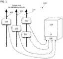
- FIG. 1illustrates an underground power distribution network with a plurality of harvesting devices located in close proximity to an underground enclosure.
- FIG. 2shows the upper half of the power harvesting current transformer positioned above the lower half in what would be the closed position for normal operation.
- the upper and lower core halvesseparate with the mechanics of the housing to facilitate mounting the core on a power line.
- FIG. 3shows an energy harvesting circuit configured to control the electrical output of an energy harvesting device and to allow for multiple instances to be paralleled.
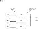
- FIG. 4is a schematic drawing showing multiple energy harvesting devices arranged in parallel to allow addition of output currents between the devices.
- FIG. 5is a flowchart describing one method of harvesting energy from a conductor of a power distribution network.
- a monitoring system 100comprises a plurality of energy harvesting devices 102 mounted to underground conductors 103 of an underground power distribution network. As shown, each of the conductors can have one or more energy harvesting device 102 mounted to the conductors. The energy harvesting devices 102 are connected to a single monitoring device 104 .
- the power distribution networkcan be a three phase AC network, or alternatively, a single-phase network, for example.
- the power distribution networkcan be any type of network, such as a 60 Hz North American network, or alternatively, a 50 Hz network such as is found in Europe and Asia, for example.
- the monitoring devicecan also be used on high voltage “transmission lines” that operate at voltages higher than 65 kV.
- the energy harvesting devicescan be mounted on each power line of a three-phase network, as shown, and can be configured to generate or harvest power from the conductors to provide power for the operation of the monitoring device 104 .
- the energy harvesting devices 102are configured to convert the changing magnetic field surrounding the distribution lines into current and/or voltage that can be rectified into DC current and used to power the monitoring devices.
- Each of the energy harvesting devicescan harvest and produce an output comprising a DC current, which can then be summed in parallel at circuit element 106 to provide a single DC current input to the monitoring device 104 for operation.
- the monitoring devicecan be configured to also measure the electric field surrounding the power lines, to record and analyze event/fault signatures, and to classify event waveforms.
- Current and electric field waveform signaturescan be monitored and catalogued by the monitoring device to build a comprehensive database of events, causes, and remedial actions.
- an application executed on a central servercan provide waveform and event signature cataloguing and profiling for access by the monitoring devices and by utility companies. This system can provide fault localization information with remedial action recommendations to utility companies, pre-emptive equipment failure alerts, and assist in power quality management of the distribution grid.
- FIG. 2illustrates one embodiment of a power harvesting system 200 , which can be included in the energy harvesting devices of FIG. 1 .
- the power harvesting systemis positioned in the energy harvesting devices so as to surround the power lines when the energy harvesting devices are installed.
- power harvesting system 200can include a split core transformer 201 having first and second core halves 204 a and 204 b .
- the split core transformercan include a primary winding (not shown) comprising the power line or conductor passing through the center of the two core halves, and a harvesting coil 202 around first core half 204 a .
- the harvesting coilcan be comprised, of any number of turns in order to establish the proper ‘turns ratio” required for the operation of the circuitry.
- the power harvesting system 200may further include a second harvesting coil around the second core half 204 b (not shown).
- the energy harvesting circuit 300can receives an input voltage 302 and an input current 304 from an energy harvesting device.
- Resistors 306represent a divider circuit configured to divide the input voltage down to a usable level for the energy harvesting circuit 300 .
- Circuit U 1is configured to measure the input current 302 and the divided input voltage via resistors 306 .
- the circuit U 1itself can comprise, for example, a plurality of cascading op-amps.
- the circuit U 1(e.g., a plurality of cascading op-amps) is designed and configured to be in balance when the input voltage 302 divided by the input current 304 is a predetermined resistance value.
- the predetermined resistanceis chosen to be 100 ohms to maximize the amount of current than can be extracted from the conductor(s) with the energy harvesting device(s).
- the output of circuit U 1goes above zero or below zero depending on if the energy harvesting circuit needs to be driven more or less to achieve balance in the circuit U 1 (i.e., to achieve the predetermined resistance value). Thus, the output of circuit U 1 determines if more or less is required to achieve the desired resistance.
- the output of circuit U 1is fed into an error amplifier 308 and pulse width modulator 310 .
- the error amplifier, pulse width modulator, boost inductor 312 , and resistor 314are configured to add or remove a load on the circuit which therefore adjusts the resistance of the circuit to the desired predetermined level.
- the pulse width modulatoroperates at a certain frequency to make load of the circuit the predetermined resistance value (e.g., 100 ohms).
- the boost inductor 312wants a constant current, so the boost inductor's output becomes the constant current.
- the amplifier US and the voltage divider formed by resistors 316put an upper limit on the output voltage, which is set to be relatively high so as to avoid entering a voltage limit state in the circuit.
- the output current through diode 318represents the maximum harvested current based on the operation of the circuit as described above.
- the energy harvesting circuit of the present disclosuretherefore is configured to sense the output voltage of the energy harvesting device and draw a ratiometric current such that the ratio of the input voltage to the input current equates to the desired loading resistance of the energy harvesting circuit.
- the energy harvesting circuitincludes a “boost” regulator and inductor which is configured to boost the input voltage to a level higher than the input.
- the schematic diagram of FIG. 3shows how U 1 , with its inputs connected to both the input voltage and input current, will be able to maintain a constant resistance loading of the harvest device, since resistance is simply voltage divided by current.
- the output of the circuitis a current whose level is set by the available power of the harvesting device, when loaded with the constant resistance.
- the output voltage of the circuitdepends on the ultimate load connected to the overall summed output. In order to limit the voltage to a practical level, U 2 will establish a certain maximum voltage.
- the present disclosurefurther provides the ability to parallel multiple devices since the output is a current source.
- the currentsdirectly add together, while the voltage of the paralleled circuit will depend upon the load placed upon the circuit. Heavy loads will keep the paralleled voltage low, while a light load will allow the paralleled voltage to rise to some practical upper limit. Once an upper voltage limit is reached, current sharing can no longer maintained. However, it is important to note that operation at the voltage limit infers that ample power is being harvested and the need for current sharing is no longer a priority.
- FIG. 4is a schematic illustration of multiple energy harvesting devices 402 arranged in parallel, as described above.
- Each energy harvesting deviceis electrically connected to an energy harvesting circuit 400 , such as the energy harvesting circuit described above.
- the output from each energy harvesting circuitcomprises a current source.
- the arrangement of FIG. 4advantageously provides an input that looks resistive but an output that looks like a current source, which allows for multiple devices to be placed in parallel to allow the currents to directly add together. The sum of all the currents can then be fed directly to a monitoring device (as described in FIG. 1 ) to provide power for the operation of the device.
- the novelty of the present disclosureis the way the energy harvesting circuit loads the harvest device (the magnetic core and coil) with a constant resistance (its most efficient load) and then creates a “current” output, so that multiple instances can be paralleled.
- This energy harvesting circuitactively performs its current summing function only at very low currents, when it matters most. As soon as enough currents are summed so that the circuit hits the upper voltage limit (and sharing stops), the monitoring device has enough power.
- the constant resistance loading mentioned hereinallows each energy harvesting core to operate at its best point of power transfer.
- FIG. 5illustrates a flowchart that describes a method for harvesting energy from one or more conductors of a power distribution network.
- energycan be harvested from one or more conductors of a power distribution network with an energy harvesting device.
- one or more energy harvesting devicescan be installed on one or more conductors of the power distribution network.
- a single harvesting deviceis installed on each conductor.
- more than one harvesting devicecan be installed on a single conductor, or on all conductors.
- the energy harvesting devicescan comprise current transformers configured to induce a current proportional to the current flowing through the main conductors.
- the methodcan further comprise inputting the voltage and current from the energy harvesting device into an energy harvesting circuit.
- each energy harvesting devicecan include its own energy harvesting circuit. This circuit may be disposed within a housing of the harvesting device, or alternatively, may be located remotely from the harvesting device but be electrically coupled to the device.
- the methodcan further comprise drawing a ratiometric current from the energy harvesting device such that a ratio of the input voltage to the input current equals a desired loading resistance of the energy harvesting circuit.
- the ratiometric currentcan be outputted to a line monitoring device.
- these devices and methodscan be scaled to include multiple energy harvesting devices and circuits.
- the methodcan include repeating these steps for additional energy harvesting devices and circuits, and summing the output currents to form a combined output current that can be used to power one or more line monitoring devices.
Landscapes
- Engineering & Computer Science (AREA)
- Power Engineering (AREA)
- Physics & Mathematics (AREA)
- General Physics & Mathematics (AREA)
- Remote Monitoring And Control Of Power-Distribution Networks (AREA)
- Control Of Voltage And Current In General (AREA)
Abstract
Description
Claims (12)
Priority Applications (1)
| Application Number | Priority Date | Filing Date | Title |
|---|---|---|---|
| US16/575,220US11476674B2 (en) | 2018-09-18 | 2019-09-18 | Systems and methods to maximize power from multiple power line energy harvesting devices |
Applications Claiming Priority (2)
| Application Number | Priority Date | Filing Date | Title |
|---|---|---|---|
| US201862732818P | 2018-09-18 | 2018-09-18 | |
| US16/575,220US11476674B2 (en) | 2018-09-18 | 2019-09-18 | Systems and methods to maximize power from multiple power line energy harvesting devices |
Publications (2)
| Publication Number | Publication Date |
|---|---|
| US20200091721A1 US20200091721A1 (en) | 2020-03-19 |
| US11476674B2true US11476674B2 (en) | 2022-10-18 |
Family
ID=69773144
Family Applications (1)
| Application Number | Title | Priority Date | Filing Date |
|---|---|---|---|
| US16/575,220ActiveUS11476674B2 (en) | 2018-09-18 | 2019-09-18 | Systems and methods to maximize power from multiple power line energy harvesting devices |
Country Status (1)
| Country | Link |
|---|---|
| US (1) | US11476674B2 (en) |
Families Citing this family (5)
| Publication number | Priority date | Publication date | Assignee | Title |
|---|---|---|---|---|
| US9229036B2 (en) | 2012-01-03 | 2016-01-05 | Sentient Energy, Inc. | Energy harvest split core design elements for ease of installation, high performance, and long term reliability |
| US11125832B2 (en) | 2018-12-13 | 2021-09-21 | Sentient Technology Holdings, LLC | Multi-phase simulation environment |
| US11609590B2 (en) | 2019-02-04 | 2023-03-21 | Sentient Technology Holdings, LLC | Power supply for electric utility underground equipment |
| WO2021229113A1 (en)* | 2020-05-15 | 2021-11-18 | Asociacion Centro Tecnologico Ceit | System for the capture and storage of electrical energy |
| GB2603448A (en)* | 2020-10-02 | 2022-08-10 | Nordic Semiconductor Asa | Energy supply circuit |
Citations (188)
| Publication number | Priority date | Publication date | Assignee | Title |
|---|---|---|---|---|
| US3075166A (en) | 1959-09-08 | 1963-01-22 | Anderson Electric Corp | Hot line clamp |
| US3558984A (en) | 1967-05-23 | 1971-01-26 | English Electric Co Ltd | A.c. system fault indicator |
| US3676740A (en) | 1971-06-01 | 1972-07-11 | Schweitzer Mfg Co E | Automatically resettable fault indicator |
| US3686531A (en) | 1971-04-08 | 1972-08-22 | Robert M Decker | Fault locating system for electrical circuits |
| US3702966A (en) | 1971-03-01 | 1972-11-14 | Schweitzer Mfg Co E | Current measuring and automatically resettable fault indicating means |
| US3708724A (en) | 1972-03-31 | 1973-01-02 | Schweitzer Mfg Co E | Signalling system responsive to fault on electric power line |
| US3715742A (en) | 1971-06-01 | 1973-02-06 | Schweiter E Mfg Co Inc | Alternating current fault indicating means |
| US3720872A (en) | 1970-09-04 | 1973-03-13 | Taft Electrosyst Inc | Power transmission fault indicator with automatic reset means |
| US3725832A (en) | 1971-10-12 | 1973-04-03 | Schwertzer E Mfg Co Inc | Magnetic core structure |
| US3755714A (en) | 1971-12-20 | 1973-08-28 | Rte Corp | Self-contained interrupting apparatus for an electric power distribution system |
| US3768011A (en) | 1970-06-09 | 1973-10-23 | W Swain | Means for measuring magnitude and direction of a direct current or permanent magnet, including clip-on direct current sensing inductor |
| US3777217A (en) | 1972-01-10 | 1973-12-04 | L Groce | Fault indicator apparatus for fault location in an electrical power distribution system |
| US3814831A (en) | 1970-11-27 | 1974-06-04 | Siemens Ag | Metal-enclosed high voltage line |
| US3816816A (en) | 1969-11-03 | 1974-06-11 | Schweitzer Mfg Co E | Indicating and automatically resettable system for detection of fault current flow in a conductor |
| US3866197A (en) | 1973-12-10 | 1975-02-11 | E O Schweitzer Manufacturing C | Means for detecting fault current in a conductor and indicating same at a remote point |
| US3876911A (en) | 1974-02-11 | 1975-04-08 | Schweitzer Mfg Co E | Fault indicator system for high voltage connectors |
| US3957329A (en) | 1974-11-01 | 1976-05-18 | I-T-E Imperial Corporation | Fault-current limiter for high power electrical transmission systems |
| US3970898A (en) | 1973-11-23 | 1976-07-20 | Zellweger Uster Ag | Method of automatically isolating a faulty section of a power line belonging to an electrical energy supply network, and arrangement for carrying out this method |
| US4063161A (en) | 1975-04-14 | 1977-12-13 | Joslyn Mfg. And Supply Co. | Buried cable fault locator with earth potential indicator and pulse generator |
| US4152643A (en) | 1978-04-10 | 1979-05-01 | E. O. Schweitzer Manufacturing Co., Inc. | Voltage indicating test point cap |
| US4161761A (en)* | 1977-09-06 | 1979-07-17 | Mcgraw-Edison Company | Proportional ground current relay |
| US4339792A (en) | 1979-04-12 | 1982-07-13 | Masayuki Yasumura | Voltage regulator using saturable transformer |
| US4378525A (en) | 1980-09-18 | 1983-03-29 | Burdick Neal M | Method and apparatus for measuring a DC current in a wire without making a direct connection to the wire |
| US4396794A (en) | 1981-03-30 | 1983-08-02 | Westinghouse Electric Corp. | Arc protection clamp and arrangement for covered overhead power distribution lines |
| US4396968A (en) | 1982-09-22 | 1983-08-02 | Westinghouse Electric Corp. | Fused distribution power system with clamp device for preventing arc damage to insulated distribution conductors |
| US4398057A (en) | 1981-03-30 | 1983-08-09 | Westinghouse Electric Corp. | Arc protection arrangement for covered overhead power distribution lines |
| US4408155A (en) | 1981-03-02 | 1983-10-04 | Bridges Electric, Inc. | Fault detector with improved response time for electrical transmission system |
| US4466071A (en) | 1981-09-28 | 1984-08-14 | Texas A&M University System | High impedance fault detection apparatus and method |
| US4559491A (en) | 1982-09-14 | 1985-12-17 | Asea Aktiebolag | Method and device for locating a fault point on a three-phase power transmission line |
| US4570231A (en) | 1984-01-27 | 1986-02-11 | Richard H. Bunch | Fault finder |
| US4584523A (en) | 1983-10-03 | 1986-04-22 | Rca Corporation | Measurement of the current flow in an electric power transmission line by detection of infrared radiation therefrom |
| US4649457A (en) | 1984-02-17 | 1987-03-10 | B. H. Tytewadd Marketing, Incorporated | Surge protection device |
| US4654573A (en) | 1985-05-17 | 1987-03-31 | Flexible Manufacturing Systems, Inc. | Power transfer device |
| US4709339A (en) | 1983-04-13 | 1987-11-24 | Fernandes Roosevelt A | Electrical power line parameter measurement apparatus and systems, including compact, line-mounted modules |
| US4714893A (en) | 1983-04-13 | 1987-12-22 | Niagara Mohawk Power Corporation | Apparatus for measuring the potential of a transmission line conductor |
| US4723220A (en) | 1983-04-13 | 1988-02-02 | Niagara Mohawk Power Corporation | Apparatus for power measuring and calculating Fourier components of power line parameters |
| US4728887A (en) | 1984-06-22 | 1988-03-01 | Davis Murray W | System for rating electric power transmission lines and equipment |
| US4746241A (en) | 1983-04-13 | 1988-05-24 | Niagara Mohawk Power Corporation | Hinge clamp for securing a sensor module on a power transmission line |
| US4766549A (en) | 1984-11-30 | 1988-08-23 | Electric Power Research Institute, Inc. | Single-ended transmission line fault locator |
| US4775839A (en) | 1985-05-21 | 1988-10-04 | Korona Messtechnik Gossau | Control apparatus for the electronic detection in a.c. power transmission lines of fault locations causing power losses |
| US4808916A (en) | 1986-11-14 | 1989-02-28 | Niagara Mohawk Power Corporation | Power supply magnetic shunt for transmission line sensor module |
| US4829298A (en) | 1983-04-13 | 1989-05-09 | Fernandes Roosevelt A | Electrical power line monitoring systems, including harmonic value measurements and relaying communications |
| US4881028A (en) | 1988-06-13 | 1989-11-14 | Bright James A | Fault detector |
| US4886980A (en) | 1985-11-05 | 1989-12-12 | Niagara Mohawk Power Corporation | Transmission line sensor apparatus operable with near zero current line conditions |
| US4904932A (en) | 1987-06-16 | 1990-02-27 | E. O. Schweitzer Manufacturing Co., Inc. | Circuit condition monitor with integrally molded test point socket and capacitive coupling |
| US4937769A (en) | 1988-06-15 | 1990-06-26 | Asea Brown Boveri Inc. | Apparatus and method for reducing transient exponential noise in a sinusoidal signal |
| US5006846A (en) | 1987-11-12 | 1991-04-09 | Granville J Michael | Power transmission line monitoring system |
| US5125738A (en) | 1988-12-13 | 1992-06-30 | Sumitomo Electric Industries, Ltd. | Apparatus and system for locating a point or a faulty point in a transmission line |
| US5138265A (en) | 1988-11-30 | 1992-08-11 | Sumitomo Electric Industries, Ltd. | Apparatus and system for locating thunderstruck point and faulty point of transmission line |
| US5159561A (en) | 1989-04-05 | 1992-10-27 | Mitsubishi Denki Kabushiki Kaisha | Zero-phase sequence current detector |
| US5181026A (en) | 1990-01-12 | 1993-01-19 | Granville Group, Inc., The | Power transmission line monitoring system |
| US5182547A (en) | 1991-01-16 | 1993-01-26 | High Voltage Maintenance | Neutral wire current monitoring for three-phase four-wire power distribution system |
| US5202812A (en) | 1988-09-21 | 1993-04-13 | Ngk Insulators, Ltd. | Apparatus for detecting faults on power transmission lines |
| US5206595A (en) | 1991-09-10 | 1993-04-27 | Electric Power Research Institute | Advanced cable fault location |
| US5220311A (en) | 1991-02-19 | 1993-06-15 | Schweitzer Edmund O Jun | Direction indicating fault indicators |
| US5428549A (en) | 1993-05-28 | 1995-06-27 | Abb Power T&D Company | Transmission line fault location system |
| US5438256A (en) | 1992-07-06 | 1995-08-01 | Gec Alsthom T & D Sa | Apparatus and method for measurement from the ground for high voltage overhead lines |
| US5473244A (en) | 1992-09-17 | 1995-12-05 | Libove; Joel M. | Apparatus for measuring voltages and currents using non-contacting sensors |
| US5495169A (en) | 1984-10-12 | 1996-02-27 | Smith; Dayle | Clamp-on current sensor |
| US5519560A (en)* | 1994-03-01 | 1996-05-21 | Eaton Corporation | Unity gain filter for current transformer |
| US5550476A (en) | 1994-09-29 | 1996-08-27 | Pacific Gas And Electric Company | Fault sensor device with radio transceiver |
| US5600248A (en) | 1995-06-21 | 1997-02-04 | Dipl.-Ing H. Horstmann Gmbh | Fault distance locator for underground cable circuits |
| US5608328A (en) | 1994-11-18 | 1997-03-04 | Radar Engineers | Method and apparatus for pin-pointing faults in electric power lines |
| US5650728A (en) | 1995-04-03 | 1997-07-22 | Hubbell Incorporated | Fault detection system including a capacitor for generating a pulse and a processor for determining admittance versus frequency of a reflected pulse |
| US5656931A (en) | 1995-01-20 | 1997-08-12 | Pacific Gas And Electric Company | Fault current sensor device with radio transceiver |
| US5682100A (en) | 1995-09-06 | 1997-10-28 | Electric Power Research Institute Inc. | System and method for locating faults in electric power cables |
| US5696788A (en) | 1995-12-26 | 1997-12-09 | Electronics And Telecommunications Research Institute | Circuit for searching fault location in a device having a plurality of application specific integrated circuits |
| US5712796A (en) | 1994-07-14 | 1998-01-27 | Hitachi Cable, Ltd. | Method for evaluating the faulted sections and states in a power transmission line |
| US5729144A (en) | 1996-12-02 | 1998-03-17 | Cummins; Kenneth L. | Systems and methods for determining location of a fault on an electric utility power distribution system |
| US5737203A (en) | 1994-10-03 | 1998-04-07 | Delco Electronics Corp. | Controlled-K resonating transformer |
| US5764065A (en) | 1996-09-20 | 1998-06-09 | Richards; Clyde N. | Remote contamination sensing device for determining contamination on insulation of power lines and substations |
| US5839093A (en) | 1996-12-31 | 1998-11-17 | Abb Transmit Oy | System for locating faults and estimating fault resistance in distribution networks with tapped loads |
| US5892430A (en) | 1994-04-25 | 1999-04-06 | Foster-Miller, Inc. | Self-powered powerline sensor |
| US5905646A (en) | 1996-12-20 | 1999-05-18 | Scanditronix Medical Ab | Power modulator |
| US5990674A (en) | 1996-07-08 | 1999-11-23 | E.O. Schweitzer Manfacturing Co., Inc. | Clamping mechanism for mounting circuit condition monitoring devices on cables of various diameters |
| US6002260A (en) | 1997-09-23 | 1999-12-14 | Pacific Gas & Electric Company | Fault sensor suitable for use in heterogenous power distribution systems |
| US6016105A (en) | 1998-04-30 | 2000-01-18 | E.O. Schweitzer Manufacturing Co., Inc. | Fault indicator providing contact closure and light indication on fault detection |
| US6043433A (en) | 1998-02-20 | 2000-03-28 | E.O. Schweitzer Manufacturing Co., Inc. | Cable clamp with universal positioning |
| US6133723A (en) | 1998-06-29 | 2000-10-17 | E. O. Schweitzer Manufacturing Co. | Fault indicator having remote light indication of fault detection |
| US6133724A (en) | 1998-06-29 | 2000-10-17 | E. O. Schweitzer Manufacturing Co. | Remote light indication fault indicator with a timed reset circuit and a manual reset circuit |
| US6288632B1 (en) | 1999-12-20 | 2001-09-11 | General Electric Company | Apparatus and method for power line communication (PLC) |
| US6292340B1 (en) | 1999-04-09 | 2001-09-18 | Electrical Materials Company | Apparatus for isolation of high impedance faults |
| US6347027B1 (en) | 1997-11-26 | 2002-02-12 | Energyline Systems, Inc. | Method and apparatus for automated reconfiguration of an electric power distribution system with enhanced protection |
| US6433698B1 (en) | 1998-04-30 | 2002-08-13 | E.O. Schweitzer Mfg. Co. | Fault indicator providing light indication on fault detection |
| US6459998B1 (en) | 1999-07-24 | 2002-10-01 | Gary R. Hoffman | Sensing downed power lines |
| US6466030B2 (en) | 2000-12-29 | 2002-10-15 | Abb Power Automation Ltd. | Systems and methods for locating faults on a transmission line with a single tapped load |
| US6466031B1 (en) | 2000-12-29 | 2002-10-15 | Abb Power Automation Ltd. | Systems and methods for locating faults on a transmission line with multiple tapped loads |
| US6477475B1 (en) | 1998-11-12 | 2002-11-05 | Nippon Kouatsu Electric Co., Ltd. | Fault point location system |
| US6483435B2 (en) | 2000-07-11 | 2002-11-19 | Abb Ab | Method and device of fault location for distribution networks |
| US6549880B1 (en) | 1999-09-15 | 2003-04-15 | Mcgraw Edison Company | Reliability of electrical distribution networks |
| US6559651B1 (en) | 2000-10-25 | 2003-05-06 | Robert G. Crick | Method for locating an open in a conductive line of an insulated conductor |
| US6566854B1 (en) | 1998-03-13 | 2003-05-20 | Florida International University | Apparatus for measuring high frequency currents |
| US6577108B2 (en) | 1999-11-24 | 2003-06-10 | American Superconductor Corporation | Voltage regulation of a utility power network |
| US6601001B1 (en) | 1999-01-13 | 2003-07-29 | Alstom Uk Ltd. | Fault-detection for power lines |
| US6622285B1 (en) | 2000-11-02 | 2003-09-16 | Hewlett-Packard Development Company, L.P. | Methods and systems for fault location |
| US6677743B1 (en) | 1999-03-05 | 2004-01-13 | Foster-Miller, Inc. | High voltage powerline sensor with a plurality of voltage sensing devices |
| US6718271B1 (en) | 1997-08-28 | 2004-04-06 | Electricity Supply Board | Fault detection apparatus and method of detecting faults in an electrical distribution network |
| US6734662B1 (en) | 2001-10-26 | 2004-05-11 | E.O. Schweitzer Manufacturing Co., Inc. | Microprocessor controlled fault indicator having led fault indication circuit with battery conservation mode |
| US20040156154A1 (en) | 2003-02-12 | 2004-08-12 | David Lazarovich | Arc fault detection for SSPC based electrical power distribution systems |
| US6798211B1 (en) | 1997-10-30 | 2004-09-28 | Remote Monitoring Systems, Inc. | Power line fault detector and analyzer |
| US6822457B2 (en) | 2003-03-27 | 2004-11-23 | Marshall B. Borchert | Method of precisely determining the location of a fault on an electrical transmission system |
| US6822576B1 (en) | 2001-10-26 | 2004-11-23 | E.O. Schweitzer Manufacturing Company, Inc. | Microprocessor controlled fault detector with circuit overload condition detection |
| EP1508146A2 (en) | 2002-05-28 | 2005-02-23 | Amperion, Inc. | Method and device for installing and removing a current transformer on and from a current-carrying power line |
| US20050073200A1 (en) | 2003-10-03 | 2005-04-07 | Divan Deepakraj M. | Distributed floating series active impedances for power transmission systems |
| US6879917B2 (en) | 2002-06-14 | 2005-04-12 | Progress Energy Carolinas Inc. | Double-ended distance-to-fault location system using time-synchronized positive-or negative-sequence quantities |
| US6894478B1 (en) | 2001-10-26 | 2005-05-17 | E.O. Schweitzer Manufacturing Company, Inc. | Fault indicator with automatically configured trip settings |
| US6914763B2 (en) | 2002-01-15 | 2005-07-05 | Wellspring Heritage, Llc | Utility control and autonomous disconnection of distributed generation from a power distribution system |
| US6917888B2 (en) | 2002-05-06 | 2005-07-12 | Arkados, Inc. | Method and system for power line network fault detection and quality monitoring |
| US6927672B2 (en) | 2001-06-12 | 2005-08-09 | Main.Net Communications Ltd. | Information transmission over power lines |
| US6949921B1 (en) | 2001-10-26 | 2005-09-27 | E.O. Schweitzer Manufacturing Co., Llc | Auto-calibration of multiple trip settings in a fault indicator |
| US6963197B1 (en) | 2002-05-31 | 2005-11-08 | E.O. Schweitzer Manufacturing Co., Llc. | Targeted timed reset fault indicator |
| US6980090B2 (en) | 2002-12-10 | 2005-12-27 | Current Technologies, Llc | Device and method for coupling with electrical distribution network infrastructure to provide communications |
| US7023691B1 (en) | 2001-10-26 | 2006-04-04 | E.O. Schweitzer Mfg. Llc | Fault Indicator with permanent and temporary fault indication |
| US7046124B2 (en) | 2003-01-21 | 2006-05-16 | Current Technologies, Llc | Power line coupling device and method of using the same |
| US7053601B1 (en) | 2001-10-26 | 2006-05-30 | E.O. Schweitzer Mfg. Co. | Microprocessor controlled fault indicator having high visibility LED fault indication |
| US7072163B2 (en) | 2004-10-19 | 2006-07-04 | Mccollough Jr Norman D | Method and apparatus for a remote electric power line conductor faulted circuit current monitoring system |
| US7076378B1 (en) | 2002-11-13 | 2006-07-11 | Current Technologies, Llc | Device and method for providing power line characteristics and diagnostics |
| US7085659B2 (en) | 2004-10-15 | 2006-08-01 | Abb Technology Ag | Dynamic energy threshold calculation for high impedance fault detection |
| US7158012B2 (en) | 1996-11-01 | 2007-01-02 | Foster-Miller, Inc. | Non-invasive powerline communications system |
| US7187275B2 (en) | 2004-10-21 | 2007-03-06 | Mccollough Jr Norman D | Method and apparatus for a remote electric power line conductor faulted circuit current, conductor temperature, conductor potential and conductor strain monitoring and alarm system |
| US7203622B2 (en) | 2002-12-23 | 2007-04-10 | Abb Research Ltd. | Value-based transmission asset maintenance management of electric power networks |
| US7272516B2 (en) | 2002-12-23 | 2007-09-18 | Abb Research | Failure rate adjustment for electric power network reliability analysis |
| US7295133B1 (en) | 2004-12-30 | 2007-11-13 | Hendrix Wire & Cable, Inc. | Electrical circuit monitoring device |
| US20080077336A1 (en) | 2006-09-25 | 2008-03-27 | Roosevelt Fernandes | Power line universal monitor |
| EP1938159A1 (en) | 2005-09-16 | 2008-07-02 | Université de Liège | Device, system and method for real-time monitoring of overhead power lines |
| US7400150B2 (en) | 2004-08-05 | 2008-07-15 | Cannon Technologies, Inc. | Remote fault monitoring in power lines |
| US7424400B2 (en) | 2004-06-04 | 2008-09-09 | Fmc Tech Limited | Method of monitoring line faults in a medium voltage network |
| US7450000B2 (en) | 2004-10-26 | 2008-11-11 | Current Technologies, Llc | Power line communications device and method |
| US7449991B2 (en) | 2002-12-10 | 2008-11-11 | Current Technologies, Llc | Power line communications device and method |
| US20090058582A1 (en) | 2007-09-04 | 2009-03-05 | Webb Thomas A | Systems and methods for extracting net-positive work from magnetic forces |
| US7508638B2 (en) | 2006-02-28 | 2009-03-24 | Siemens Energy & Automation, Inc. | Devices, systems, and methods for providing electrical power |
| US7518529B2 (en) | 2003-01-31 | 2009-04-14 | Fmc Tech Limited | Monitoring device for a medium voltage overhead line |
| US7532012B2 (en) | 2006-07-07 | 2009-05-12 | Ambient Corporation | Detection and monitoring of partial discharge of a power line |
| US7557563B2 (en) | 2005-01-19 | 2009-07-07 | Power Measurement Ltd. | Current sensor assembly |
| US7586380B1 (en)* | 2008-03-12 | 2009-09-08 | Kawasaki Microelectronics, Inc. | Bias circuit to stabilize oscillation in ring oscillator, oscillator, and method to stabilize oscillation in ring oscillator |
| US7626794B2 (en) | 2005-10-18 | 2009-12-01 | Schweitzer Engineering Laboratories, Inc. | Systems, methods, and apparatus for indicating faults within a power circuit utilizing dynamically modified inrush restraint |
| US7633262B2 (en) | 2005-03-11 | 2009-12-15 | Lindsey Manufacturing Company | Power supply for underground and pad mounted power distribution systems |
| US20090309754A1 (en) | 2008-06-16 | 2009-12-17 | Jimmy Bou | Wireless current transformer |
| US7672812B2 (en) | 2006-11-01 | 2010-03-02 | Abb Research Ltd. | Cable fault detection |
| US7683798B2 (en) | 2006-07-07 | 2010-03-23 | Ssi Power, Llc | Current monitoring device for high voltage electric power lines |
| US20100085036A1 (en) | 2007-11-02 | 2010-04-08 | Cooper Technologies Company | Overhead Communicating Device |
| US7701356B2 (en) | 2006-03-16 | 2010-04-20 | Power Monitors, Inc. | Underground monitoring system and method |
| US7714592B2 (en) | 2007-11-07 | 2010-05-11 | Current Technologies, Llc | System and method for determining the impedance of a medium voltage power line |
| US7720619B2 (en) | 2006-08-04 | 2010-05-18 | Schweitzer Engineering Laboratories, Inc. | Systems and methods for detecting high-impedance faults in a multi-grounded power distribution system |
| US7725295B2 (en) | 2006-11-01 | 2010-05-25 | Abb Research Ltd. | Cable fault detection |
| US7742393B2 (en) | 2003-07-24 | 2010-06-22 | Hunt Technologies, Inc. | Locating endpoints in a power line communication system |
| US7764943B2 (en) | 2006-03-27 | 2010-07-27 | Current Technologies, Llc | Overhead and underground power line communication system and method using a bypass |
| US7795877B2 (en) | 2006-11-02 | 2010-09-14 | Current Technologies, Llc | Power line communication and power distribution parameter measurement system and method |
| US7795994B2 (en) | 2007-06-26 | 2010-09-14 | Current Technologies, Llc | Power line coupling device and method |
| US7804280B2 (en) | 2006-11-02 | 2010-09-28 | Current Technologies, Llc | Method and system for providing power factor correction in a power distribution system |
| US20110032739A1 (en) | 2007-08-31 | 2011-02-10 | Abb Technology Ag | Method and device to compensate for an asymmetrical dc bias current in a power transformer connected to a high voltage converter |
| US7930141B2 (en) | 2007-11-02 | 2011-04-19 | Cooper Technologies Company | Communicating faulted circuit indicator apparatus and method of use thereof |
| EP2340592A1 (en) | 2008-10-08 | 2011-07-06 | Cooper Technologies Company | Overhead communicating device |
| US20120039062A1 (en) | 2010-08-10 | 2012-02-16 | Mcbee Bruce W | Apparatus for Mounting an Overhead Monitoring Device |
| US20120081824A1 (en)* | 2010-09-29 | 2012-04-05 | Krishnaswamy Gururaj Narendra | Method and apparatus for sub-harmonic protection |
| US20120236611A1 (en) | 2011-03-16 | 2012-09-20 | Marmon Utility Llc | Power line current fed power supplies producing stable load currents and related methods |
| US20130076323A1 (en)* | 2011-09-23 | 2013-03-28 | Tsung-Wei Huang | Dynamic dropout control of a power supply |
| US8421444B2 (en) | 2009-12-31 | 2013-04-16 | Schneider Electric USA, Inc. | Compact, two stage, zero flux electronically compensated current or voltage transducer employing dual magnetic cores having substantially dissimilar magnetic characteristics |
| US20130162136A1 (en) | 2011-10-18 | 2013-06-27 | David A. Baldwin | Arc devices and moving arc couples |
| US20130169361A1 (en)* | 2011-12-30 | 2013-07-04 | Dialog Semiconductor Gmbh | Multi-Stage Fully Differential Amplifier with Controlled Common Mode Voltage |
| US8497781B2 (en) | 2004-10-22 | 2013-07-30 | Underground Systems, Inc. | Power supply and communications controller |
| US20140062221A1 (en) | 2011-05-30 | 2014-03-06 | Konstantinos Papastergiou | System For Distributing Electric Power To An Electrical Grid |
| US20140145858A1 (en) | 2010-09-22 | 2014-05-29 | Gary Miller | Transmission line measuring device and method for connectivity and monitoring |
| US20140174170A1 (en) | 2012-12-21 | 2014-06-26 | Murray W. Davis | Portable self powered line mounted conductor ice thickness measuring system for overhead electric power lines |
| US20140192458A1 (en) | 2013-01-04 | 2014-07-10 | General Electric Company | Power distribution systems and methods of operating a power distribution system including arc flash detection |
| US8786292B2 (en) | 2010-12-06 | 2014-07-22 | Sentient Energy, Inc. | Power conductor monitoring device and method of calibration |
| US20140226366A1 (en) | 2011-12-05 | 2014-08-14 | Mitsubishi Electric Corporation | Signal transmission circuit |
| US20140260598A1 (en) | 2013-03-14 | 2014-09-18 | Hubbell Incorporated | Apparatuses, Systems and Methods for Determining Effective Wind Speed |
| US8847576B1 (en)* | 2012-08-30 | 2014-09-30 | Continental Control Systems, Llc | Phase compensation method and apparatus for current transformers |
| US20150002165A1 (en)* | 2013-06-28 | 2015-01-01 | Honeywell International Inc. | Power transformation system with characterization |
| US20150198667A1 (en) | 2014-01-16 | 2015-07-16 | Vanguard Instruments Company, Inc. | Dual ground breaker testing system |
| US9182429B2 (en) | 2012-01-04 | 2015-11-10 | Sentient Energy, Inc. | Distribution line clamp force using DC bias on coil |
| US20150372626A1 (en)* | 2013-01-11 | 2015-12-24 | Aktiebolaget Skf | Voltage adjustment for an energy harvester |
| US20150378379A1 (en)* | 2014-06-27 | 2015-12-31 | Dialog Semiconductor Gmbh | Voltage Regulator Output Overvoltage Compensation |
| US9229036B2 (en) | 2012-01-03 | 2016-01-05 | Sentient Energy, Inc. | Energy harvest split core design elements for ease of installation, high performance, and long term reliability |
| US20160164310A1 (en)* | 2013-06-28 | 2016-06-09 | Honeywell International Inc. | Source management for a power transformation system |
| US20160276950A1 (en)* | 2014-03-04 | 2016-09-22 | Tera Energy System Solution Co. Ltd | Unit current transformer device and magnetic induction power supplying device for linearly controlling output power by using the same |
| US9581624B2 (en) | 2014-08-19 | 2017-02-28 | Southern States, Llc | Corona avoidance electric power line monitoring, communication and response system |
| US20170199533A1 (en) | 2016-01-11 | 2017-07-13 | Electric Power Research Institute Inc. | Energy harvesting device |
| US20180003744A1 (en)* | 2013-06-28 | 2018-01-04 | Honeywell International Inc. | Power transformation self characterization mode |
| US9954354B2 (en) | 2015-01-06 | 2018-04-24 | Sentient Energy, Inc. | Methods and apparatus for mitigation of damage of power line assets from traveling electrical arcs |
| US20180143234A1 (en) | 2016-11-18 | 2018-05-24 | Dennis Allen Saxby | Overhead power line sensor |
| US9984818B2 (en) | 2015-12-04 | 2018-05-29 | Sentient Energy, Inc. | Current harvesting transformer with protection from high currents |
| US20180287370A1 (en)* | 2013-09-26 | 2018-10-04 | James J. Kinsella | Low-cost, full-range electronc overload relay device |
| US20190021154A1 (en)* | 2015-08-04 | 2019-01-17 | Innosys. Inc. | Solid State Lighting Systems |
| US10298208B1 (en)* | 2018-06-08 | 2019-05-21 | Siemens Aktiengesellschaft | Dynamic impedance system for an increased range of operation of an instrument transformer |
| US20200052488A1 (en)* | 2018-08-07 | 2020-02-13 | Aclara Technologies Llc | Device and method for harvesting energy from a power line magnetic field |
| US20200373850A1 (en)* | 2017-08-11 | 2020-11-26 | Laki Power EHF. | System for generating a power output and corresponding use |
- 2019
- 2019-09-18USUS16/575,220patent/US11476674B2/enactiveActive
Patent Citations (194)
| Publication number | Priority date | Publication date | Assignee | Title |
|---|---|---|---|---|
| US3075166A (en) | 1959-09-08 | 1963-01-22 | Anderson Electric Corp | Hot line clamp |
| US3558984A (en) | 1967-05-23 | 1971-01-26 | English Electric Co Ltd | A.c. system fault indicator |
| US3816816A (en) | 1969-11-03 | 1974-06-11 | Schweitzer Mfg Co E | Indicating and automatically resettable system for detection of fault current flow in a conductor |
| US3768011A (en) | 1970-06-09 | 1973-10-23 | W Swain | Means for measuring magnitude and direction of a direct current or permanent magnet, including clip-on direct current sensing inductor |
| US3720872A (en) | 1970-09-04 | 1973-03-13 | Taft Electrosyst Inc | Power transmission fault indicator with automatic reset means |
| US3814831A (en) | 1970-11-27 | 1974-06-04 | Siemens Ag | Metal-enclosed high voltage line |
| US3702966A (en) | 1971-03-01 | 1972-11-14 | Schweitzer Mfg Co E | Current measuring and automatically resettable fault indicating means |
| US3686531A (en) | 1971-04-08 | 1972-08-22 | Robert M Decker | Fault locating system for electrical circuits |
| US3715742A (en) | 1971-06-01 | 1973-02-06 | Schweiter E Mfg Co Inc | Alternating current fault indicating means |
| US3676740A (en) | 1971-06-01 | 1972-07-11 | Schweitzer Mfg Co E | Automatically resettable fault indicator |
| US3725832A (en) | 1971-10-12 | 1973-04-03 | Schwertzer E Mfg Co Inc | Magnetic core structure |
| US3755714A (en) | 1971-12-20 | 1973-08-28 | Rte Corp | Self-contained interrupting apparatus for an electric power distribution system |
| US3777217A (en) | 1972-01-10 | 1973-12-04 | L Groce | Fault indicator apparatus for fault location in an electrical power distribution system |
| US3708724A (en) | 1972-03-31 | 1973-01-02 | Schweitzer Mfg Co E | Signalling system responsive to fault on electric power line |
| US3970898A (en) | 1973-11-23 | 1976-07-20 | Zellweger Uster Ag | Method of automatically isolating a faulty section of a power line belonging to an electrical energy supply network, and arrangement for carrying out this method |
| US3866197A (en) | 1973-12-10 | 1975-02-11 | E O Schweitzer Manufacturing C | Means for detecting fault current in a conductor and indicating same at a remote point |
| US3876911A (en) | 1974-02-11 | 1975-04-08 | Schweitzer Mfg Co E | Fault indicator system for high voltage connectors |
| US3957329A (en) | 1974-11-01 | 1976-05-18 | I-T-E Imperial Corporation | Fault-current limiter for high power electrical transmission systems |
| US4063161A (en) | 1975-04-14 | 1977-12-13 | Joslyn Mfg. And Supply Co. | Buried cable fault locator with earth potential indicator and pulse generator |
| US4161761A (en)* | 1977-09-06 | 1979-07-17 | Mcgraw-Edison Company | Proportional ground current relay |
| US4152643A (en) | 1978-04-10 | 1979-05-01 | E. O. Schweitzer Manufacturing Co., Inc. | Voltage indicating test point cap |
| US4339792A (en) | 1979-04-12 | 1982-07-13 | Masayuki Yasumura | Voltage regulator using saturable transformer |
| US4378525A (en) | 1980-09-18 | 1983-03-29 | Burdick Neal M | Method and apparatus for measuring a DC current in a wire without making a direct connection to the wire |
| US4408155A (en) | 1981-03-02 | 1983-10-04 | Bridges Electric, Inc. | Fault detector with improved response time for electrical transmission system |
| US4396794A (en) | 1981-03-30 | 1983-08-02 | Westinghouse Electric Corp. | Arc protection clamp and arrangement for covered overhead power distribution lines |
| US4398057A (en) | 1981-03-30 | 1983-08-09 | Westinghouse Electric Corp. | Arc protection arrangement for covered overhead power distribution lines |
| US4466071A (en) | 1981-09-28 | 1984-08-14 | Texas A&M University System | High impedance fault detection apparatus and method |
| US4559491A (en) | 1982-09-14 | 1985-12-17 | Asea Aktiebolag | Method and device for locating a fault point on a three-phase power transmission line |
| US4396968A (en) | 1982-09-22 | 1983-08-02 | Westinghouse Electric Corp. | Fused distribution power system with clamp device for preventing arc damage to insulated distribution conductors |
| US4709339A (en) | 1983-04-13 | 1987-11-24 | Fernandes Roosevelt A | Electrical power line parameter measurement apparatus and systems, including compact, line-mounted modules |
| US4746241A (en) | 1983-04-13 | 1988-05-24 | Niagara Mohawk Power Corporation | Hinge clamp for securing a sensor module on a power transmission line |
| US4829298A (en) | 1983-04-13 | 1989-05-09 | Fernandes Roosevelt A | Electrical power line monitoring systems, including harmonic value measurements and relaying communications |
| US4714893A (en) | 1983-04-13 | 1987-12-22 | Niagara Mohawk Power Corporation | Apparatus for measuring the potential of a transmission line conductor |
| US4723220A (en) | 1983-04-13 | 1988-02-02 | Niagara Mohawk Power Corporation | Apparatus for power measuring and calculating Fourier components of power line parameters |
| US4584523A (en) | 1983-10-03 | 1986-04-22 | Rca Corporation | Measurement of the current flow in an electric power transmission line by detection of infrared radiation therefrom |
| US4570231A (en) | 1984-01-27 | 1986-02-11 | Richard H. Bunch | Fault finder |
| US4649457A (en) | 1984-02-17 | 1987-03-10 | B. H. Tytewadd Marketing, Incorporated | Surge protection device |
| US4728887A (en) | 1984-06-22 | 1988-03-01 | Davis Murray W | System for rating electric power transmission lines and equipment |
| US5495169A (en) | 1984-10-12 | 1996-02-27 | Smith; Dayle | Clamp-on current sensor |
| US4766549A (en) | 1984-11-30 | 1988-08-23 | Electric Power Research Institute, Inc. | Single-ended transmission line fault locator |
| US4654573A (en) | 1985-05-17 | 1987-03-31 | Flexible Manufacturing Systems, Inc. | Power transfer device |
| US4775839A (en) | 1985-05-21 | 1988-10-04 | Korona Messtechnik Gossau | Control apparatus for the electronic detection in a.c. power transmission lines of fault locations causing power losses |
| US4886980A (en) | 1985-11-05 | 1989-12-12 | Niagara Mohawk Power Corporation | Transmission line sensor apparatus operable with near zero current line conditions |
| US4808916A (en) | 1986-11-14 | 1989-02-28 | Niagara Mohawk Power Corporation | Power supply magnetic shunt for transmission line sensor module |
| US4904932A (en) | 1987-06-16 | 1990-02-27 | E. O. Schweitzer Manufacturing Co., Inc. | Circuit condition monitor with integrally molded test point socket and capacitive coupling |
| US5006846A (en) | 1987-11-12 | 1991-04-09 | Granville J Michael | Power transmission line monitoring system |
| US4881028A (en) | 1988-06-13 | 1989-11-14 | Bright James A | Fault detector |
| US4937769A (en) | 1988-06-15 | 1990-06-26 | Asea Brown Boveri Inc. | Apparatus and method for reducing transient exponential noise in a sinusoidal signal |
| US5202812A (en) | 1988-09-21 | 1993-04-13 | Ngk Insulators, Ltd. | Apparatus for detecting faults on power transmission lines |
| US5138265A (en) | 1988-11-30 | 1992-08-11 | Sumitomo Electric Industries, Ltd. | Apparatus and system for locating thunderstruck point and faulty point of transmission line |
| US5125738A (en) | 1988-12-13 | 1992-06-30 | Sumitomo Electric Industries, Ltd. | Apparatus and system for locating a point or a faulty point in a transmission line |
| US5159561A (en) | 1989-04-05 | 1992-10-27 | Mitsubishi Denki Kabushiki Kaisha | Zero-phase sequence current detector |
| US5181026A (en) | 1990-01-12 | 1993-01-19 | Granville Group, Inc., The | Power transmission line monitoring system |
| US5182547A (en) | 1991-01-16 | 1993-01-26 | High Voltage Maintenance | Neutral wire current monitoring for three-phase four-wire power distribution system |
| US5220311A (en) | 1991-02-19 | 1993-06-15 | Schweitzer Edmund O Jun | Direction indicating fault indicators |
| US5206595A (en) | 1991-09-10 | 1993-04-27 | Electric Power Research Institute | Advanced cable fault location |
| US5438256A (en) | 1992-07-06 | 1995-08-01 | Gec Alsthom T & D Sa | Apparatus and method for measurement from the ground for high voltage overhead lines |
| US5473244A (en) | 1992-09-17 | 1995-12-05 | Libove; Joel M. | Apparatus for measuring voltages and currents using non-contacting sensors |
| US5428549A (en) | 1993-05-28 | 1995-06-27 | Abb Power T&D Company | Transmission line fault location system |
| US5519560A (en)* | 1994-03-01 | 1996-05-21 | Eaton Corporation | Unity gain filter for current transformer |
| US5892430A (en) | 1994-04-25 | 1999-04-06 | Foster-Miller, Inc. | Self-powered powerline sensor |
| US5712796A (en) | 1994-07-14 | 1998-01-27 | Hitachi Cable, Ltd. | Method for evaluating the faulted sections and states in a power transmission line |
| US5550476A (en) | 1994-09-29 | 1996-08-27 | Pacific Gas And Electric Company | Fault sensor device with radio transceiver |
| US5737203A (en) | 1994-10-03 | 1998-04-07 | Delco Electronics Corp. | Controlled-K resonating transformer |
| US5608328A (en) | 1994-11-18 | 1997-03-04 | Radar Engineers | Method and apparatus for pin-pointing faults in electric power lines |
| US5656931A (en) | 1995-01-20 | 1997-08-12 | Pacific Gas And Electric Company | Fault current sensor device with radio transceiver |
| US5650728A (en) | 1995-04-03 | 1997-07-22 | Hubbell Incorporated | Fault detection system including a capacitor for generating a pulse and a processor for determining admittance versus frequency of a reflected pulse |
| US5600248A (en) | 1995-06-21 | 1997-02-04 | Dipl.-Ing H. Horstmann Gmbh | Fault distance locator for underground cable circuits |
| US5682100A (en) | 1995-09-06 | 1997-10-28 | Electric Power Research Institute Inc. | System and method for locating faults in electric power cables |
| US5696788A (en) | 1995-12-26 | 1997-12-09 | Electronics And Telecommunications Research Institute | Circuit for searching fault location in a device having a plurality of application specific integrated circuits |
| US5990674A (en) | 1996-07-08 | 1999-11-23 | E.O. Schweitzer Manfacturing Co., Inc. | Clamping mechanism for mounting circuit condition monitoring devices on cables of various diameters |
| US5764065A (en) | 1996-09-20 | 1998-06-09 | Richards; Clyde N. | Remote contamination sensing device for determining contamination on insulation of power lines and substations |
| US7158012B2 (en) | 1996-11-01 | 2007-01-02 | Foster-Miller, Inc. | Non-invasive powerline communications system |
| US5729144A (en) | 1996-12-02 | 1998-03-17 | Cummins; Kenneth L. | Systems and methods for determining location of a fault on an electric utility power distribution system |
| US5905646A (en) | 1996-12-20 | 1999-05-18 | Scanditronix Medical Ab | Power modulator |
| US5839093A (en) | 1996-12-31 | 1998-11-17 | Abb Transmit Oy | System for locating faults and estimating fault resistance in distribution networks with tapped loads |
| US6718271B1 (en) | 1997-08-28 | 2004-04-06 | Electricity Supply Board | Fault detection apparatus and method of detecting faults in an electrical distribution network |
| US6002260A (en) | 1997-09-23 | 1999-12-14 | Pacific Gas & Electric Company | Fault sensor suitable for use in heterogenous power distribution systems |
| US6798211B1 (en) | 1997-10-30 | 2004-09-28 | Remote Monitoring Systems, Inc. | Power line fault detector and analyzer |
| US6347027B1 (en) | 1997-11-26 | 2002-02-12 | Energyline Systems, Inc. | Method and apparatus for automated reconfiguration of an electric power distribution system with enhanced protection |
| US6043433A (en) | 1998-02-20 | 2000-03-28 | E.O. Schweitzer Manufacturing Co., Inc. | Cable clamp with universal positioning |
| US6566854B1 (en) | 1998-03-13 | 2003-05-20 | Florida International University | Apparatus for measuring high frequency currents |
| US6433698B1 (en) | 1998-04-30 | 2002-08-13 | E.O. Schweitzer Mfg. Co. | Fault indicator providing light indication on fault detection |
| US6016105A (en) | 1998-04-30 | 2000-01-18 | E.O. Schweitzer Manufacturing Co., Inc. | Fault indicator providing contact closure and light indication on fault detection |
| US6133724A (en) | 1998-06-29 | 2000-10-17 | E. O. Schweitzer Manufacturing Co. | Remote light indication fault indicator with a timed reset circuit and a manual reset circuit |
| US6133723A (en) | 1998-06-29 | 2000-10-17 | E. O. Schweitzer Manufacturing Co. | Fault indicator having remote light indication of fault detection |
| US6477475B1 (en) | 1998-11-12 | 2002-11-05 | Nippon Kouatsu Electric Co., Ltd. | Fault point location system |
| US6601001B1 (en) | 1999-01-13 | 2003-07-29 | Alstom Uk Ltd. | Fault-detection for power lines |
| US6677743B1 (en) | 1999-03-05 | 2004-01-13 | Foster-Miller, Inc. | High voltage powerline sensor with a plurality of voltage sensing devices |
| US6292340B1 (en) | 1999-04-09 | 2001-09-18 | Electrical Materials Company | Apparatus for isolation of high impedance faults |
| US6459998B1 (en) | 1999-07-24 | 2002-10-01 | Gary R. Hoffman | Sensing downed power lines |
| US6549880B1 (en) | 1999-09-15 | 2003-04-15 | Mcgraw Edison Company | Reliability of electrical distribution networks |
| US6577108B2 (en) | 1999-11-24 | 2003-06-10 | American Superconductor Corporation | Voltage regulation of a utility power network |
| US6288632B1 (en) | 1999-12-20 | 2001-09-11 | General Electric Company | Apparatus and method for power line communication (PLC) |
| US6483435B2 (en) | 2000-07-11 | 2002-11-19 | Abb Ab | Method and device of fault location for distribution networks |
| US6559651B1 (en) | 2000-10-25 | 2003-05-06 | Robert G. Crick | Method for locating an open in a conductive line of an insulated conductor |
| US6622285B1 (en) | 2000-11-02 | 2003-09-16 | Hewlett-Packard Development Company, L.P. | Methods and systems for fault location |
| US6466031B1 (en) | 2000-12-29 | 2002-10-15 | Abb Power Automation Ltd. | Systems and methods for locating faults on a transmission line with multiple tapped loads |
| US6466030B2 (en) | 2000-12-29 | 2002-10-15 | Abb Power Automation Ltd. | Systems and methods for locating faults on a transmission line with a single tapped load |
| US6927672B2 (en) | 2001-06-12 | 2005-08-09 | Main.Net Communications Ltd. | Information transmission over power lines |
| US7053601B1 (en) | 2001-10-26 | 2006-05-30 | E.O. Schweitzer Mfg. Co. | Microprocessor controlled fault indicator having high visibility LED fault indication |
| US6822576B1 (en) | 2001-10-26 | 2004-11-23 | E.O. Schweitzer Manufacturing Company, Inc. | Microprocessor controlled fault detector with circuit overload condition detection |
| US6734662B1 (en) | 2001-10-26 | 2004-05-11 | E.O. Schweitzer Manufacturing Co., Inc. | Microprocessor controlled fault indicator having led fault indication circuit with battery conservation mode |
| US7023691B1 (en) | 2001-10-26 | 2006-04-04 | E.O. Schweitzer Mfg. Llc | Fault Indicator with permanent and temporary fault indication |
| US6894478B1 (en) | 2001-10-26 | 2005-05-17 | E.O. Schweitzer Manufacturing Company, Inc. | Fault indicator with automatically configured trip settings |
| US7106048B1 (en) | 2001-10-26 | 2006-09-12 | Schweitzer Engineering Laboratories, Inc. | Fault indicator with auto-configuration for overhead or underground application |
| US6949921B1 (en) | 2001-10-26 | 2005-09-27 | E.O. Schweitzer Manufacturing Co., Llc | Auto-calibration of multiple trip settings in a fault indicator |
| US6914763B2 (en) | 2002-01-15 | 2005-07-05 | Wellspring Heritage, Llc | Utility control and autonomous disconnection of distributed generation from a power distribution system |
| US6917888B2 (en) | 2002-05-06 | 2005-07-12 | Arkados, Inc. | Method and system for power line network fault detection and quality monitoring |
| EP1508146A2 (en) | 2002-05-28 | 2005-02-23 | Amperion, Inc. | Method and device for installing and removing a current transformer on and from a current-carrying power line |
| US6963197B1 (en) | 2002-05-31 | 2005-11-08 | E.O. Schweitzer Manufacturing Co., Llc. | Targeted timed reset fault indicator |
| US6879917B2 (en) | 2002-06-14 | 2005-04-12 | Progress Energy Carolinas Inc. | Double-ended distance-to-fault location system using time-synchronized positive-or negative-sequence quantities |
| US7076378B1 (en) | 2002-11-13 | 2006-07-11 | Current Technologies, Llc | Device and method for providing power line characteristics and diagnostics |
| US6980090B2 (en) | 2002-12-10 | 2005-12-27 | Current Technologies, Llc | Device and method for coupling with electrical distribution network infrastructure to provide communications |
| US7449991B2 (en) | 2002-12-10 | 2008-11-11 | Current Technologies, Llc | Power line communications device and method |
| US7203622B2 (en) | 2002-12-23 | 2007-04-10 | Abb Research Ltd. | Value-based transmission asset maintenance management of electric power networks |
| US7272516B2 (en) | 2002-12-23 | 2007-09-18 | Abb Research | Failure rate adjustment for electric power network reliability analysis |
| US7046124B2 (en) | 2003-01-21 | 2006-05-16 | Current Technologies, Llc | Power line coupling device and method of using the same |
| US7518529B2 (en) | 2003-01-31 | 2009-04-14 | Fmc Tech Limited | Monitoring device for a medium voltage overhead line |
| US20040156154A1 (en) | 2003-02-12 | 2004-08-12 | David Lazarovich | Arc fault detection for SSPC based electrical power distribution systems |
| US6822457B2 (en) | 2003-03-27 | 2004-11-23 | Marshall B. Borchert | Method of precisely determining the location of a fault on an electrical transmission system |
| US7742393B2 (en) | 2003-07-24 | 2010-06-22 | Hunt Technologies, Inc. | Locating endpoints in a power line communication system |
| US20050073200A1 (en) | 2003-10-03 | 2005-04-07 | Divan Deepakraj M. | Distributed floating series active impedances for power transmission systems |
| US7424400B2 (en) | 2004-06-04 | 2008-09-09 | Fmc Tech Limited | Method of monitoring line faults in a medium voltage network |
| US7400150B2 (en) | 2004-08-05 | 2008-07-15 | Cannon Technologies, Inc. | Remote fault monitoring in power lines |
| US7085659B2 (en) | 2004-10-15 | 2006-08-01 | Abb Technology Ag | Dynamic energy threshold calculation for high impedance fault detection |
| US7072163B2 (en) | 2004-10-19 | 2006-07-04 | Mccollough Jr Norman D | Method and apparatus for a remote electric power line conductor faulted circuit current monitoring system |
| US7187275B2 (en) | 2004-10-21 | 2007-03-06 | Mccollough Jr Norman D | Method and apparatus for a remote electric power line conductor faulted circuit current, conductor temperature, conductor potential and conductor strain monitoring and alarm system |
| US8497781B2 (en) | 2004-10-22 | 2013-07-30 | Underground Systems, Inc. | Power supply and communications controller |
| US7450000B2 (en) | 2004-10-26 | 2008-11-11 | Current Technologies, Llc | Power line communications device and method |
| US7295133B1 (en) | 2004-12-30 | 2007-11-13 | Hendrix Wire & Cable, Inc. | Electrical circuit monitoring device |
| US7557563B2 (en) | 2005-01-19 | 2009-07-07 | Power Measurement Ltd. | Current sensor assembly |
| US7633262B2 (en) | 2005-03-11 | 2009-12-15 | Lindsey Manufacturing Company | Power supply for underground and pad mounted power distribution systems |
| EP1938159A1 (en) | 2005-09-16 | 2008-07-02 | Université de Liège | Device, system and method for real-time monitoring of overhead power lines |
| US7626794B2 (en) | 2005-10-18 | 2009-12-01 | Schweitzer Engineering Laboratories, Inc. | Systems, methods, and apparatus for indicating faults within a power circuit utilizing dynamically modified inrush restraint |
| US7508638B2 (en) | 2006-02-28 | 2009-03-24 | Siemens Energy & Automation, Inc. | Devices, systems, and methods for providing electrical power |
| US7701356B2 (en) | 2006-03-16 | 2010-04-20 | Power Monitors, Inc. | Underground monitoring system and method |
| US7764943B2 (en) | 2006-03-27 | 2010-07-27 | Current Technologies, Llc | Overhead and underground power line communication system and method using a bypass |
| US7683798B2 (en) | 2006-07-07 | 2010-03-23 | Ssi Power, Llc | Current monitoring device for high voltage electric power lines |
| US7532012B2 (en) | 2006-07-07 | 2009-05-12 | Ambient Corporation | Detection and monitoring of partial discharge of a power line |
| US7720619B2 (en) | 2006-08-04 | 2010-05-18 | Schweitzer Engineering Laboratories, Inc. | Systems and methods for detecting high-impedance faults in a multi-grounded power distribution system |
| US20080077336A1 (en) | 2006-09-25 | 2008-03-27 | Roosevelt Fernandes | Power line universal monitor |
| US7672812B2 (en) | 2006-11-01 | 2010-03-02 | Abb Research Ltd. | Cable fault detection |
| US7725295B2 (en) | 2006-11-01 | 2010-05-25 | Abb Research Ltd. | Cable fault detection |
| US7795877B2 (en) | 2006-11-02 | 2010-09-14 | Current Technologies, Llc | Power line communication and power distribution parameter measurement system and method |
| US7804280B2 (en) | 2006-11-02 | 2010-09-28 | Current Technologies, Llc | Method and system for providing power factor correction in a power distribution system |
| US7795994B2 (en) | 2007-06-26 | 2010-09-14 | Current Technologies, Llc | Power line coupling device and method |
| US20110032739A1 (en) | 2007-08-31 | 2011-02-10 | Abb Technology Ag | Method and device to compensate for an asymmetrical dc bias current in a power transformer connected to a high voltage converter |
| US20090058582A1 (en) | 2007-09-04 | 2009-03-05 | Webb Thomas A | Systems and methods for extracting net-positive work from magnetic forces |
| US8594956B2 (en) | 2007-11-02 | 2013-11-26 | Cooper Technologies Company | Power line energy harvesting power supply |
| US20100085036A1 (en) | 2007-11-02 | 2010-04-08 | Cooper Technologies Company | Overhead Communicating Device |
| US7930141B2 (en) | 2007-11-02 | 2011-04-19 | Cooper Technologies Company | Communicating faulted circuit indicator apparatus and method of use thereof |
| US9383394B2 (en)* | 2007-11-02 | 2016-07-05 | Cooper Technologies Company | Overhead communicating device |
| US7714592B2 (en) | 2007-11-07 | 2010-05-11 | Current Technologies, Llc | System and method for determining the impedance of a medium voltage power line |
| US7586380B1 (en)* | 2008-03-12 | 2009-09-08 | Kawasaki Microelectronics, Inc. | Bias circuit to stabilize oscillation in ring oscillator, oscillator, and method to stabilize oscillation in ring oscillator |
| US20090309754A1 (en) | 2008-06-16 | 2009-12-17 | Jimmy Bou | Wireless current transformer |
| EP2340592A1 (en) | 2008-10-08 | 2011-07-06 | Cooper Technologies Company | Overhead communicating device |
| EP2350764A1 (en) | 2008-10-08 | 2011-08-03 | Cooper Technologies Company | Power line energy harvesting power supply |
| US8421444B2 (en) | 2009-12-31 | 2013-04-16 | Schneider Electric USA, Inc. | Compact, two stage, zero flux electronically compensated current or voltage transducer employing dual magnetic cores having substantially dissimilar magnetic characteristics |
| US20120039062A1 (en) | 2010-08-10 | 2012-02-16 | Mcbee Bruce W | Apparatus for Mounting an Overhead Monitoring Device |
| US20140145858A1 (en) | 2010-09-22 | 2014-05-29 | Gary Miller | Transmission line measuring device and method for connectivity and monitoring |
| US20120081824A1 (en)* | 2010-09-29 | 2012-04-05 | Krishnaswamy Gururaj Narendra | Method and apparatus for sub-harmonic protection |
| US8786292B2 (en) | 2010-12-06 | 2014-07-22 | Sentient Energy, Inc. | Power conductor monitoring device and method of calibration |
| US20120236611A1 (en) | 2011-03-16 | 2012-09-20 | Marmon Utility Llc | Power line current fed power supplies producing stable load currents and related methods |
| US20140062221A1 (en) | 2011-05-30 | 2014-03-06 | Konstantinos Papastergiou | System For Distributing Electric Power To An Electrical Grid |
| US20130076323A1 (en)* | 2011-09-23 | 2013-03-28 | Tsung-Wei Huang | Dynamic dropout control of a power supply |
| US20130162136A1 (en) | 2011-10-18 | 2013-06-27 | David A. Baldwin | Arc devices and moving arc couples |
| US20140226366A1 (en) | 2011-12-05 | 2014-08-14 | Mitsubishi Electric Corporation | Signal transmission circuit |
| US20130169361A1 (en)* | 2011-12-30 | 2013-07-04 | Dialog Semiconductor Gmbh | Multi-Stage Fully Differential Amplifier with Controlled Common Mode Voltage |
| US9229036B2 (en) | 2012-01-03 | 2016-01-05 | Sentient Energy, Inc. | Energy harvest split core design elements for ease of installation, high performance, and long term reliability |
| US20160116505A1 (en) | 2012-01-03 | 2016-04-28 | Michael Kast | Energy harvest split core design elements for ease of installation, high performance, and long term reliability |
| US9182429B2 (en) | 2012-01-04 | 2015-11-10 | Sentient Energy, Inc. | Distribution line clamp force using DC bias on coil |
| US9448257B2 (en) | 2012-01-04 | 2016-09-20 | Sentient Energy, Inc. | Distribution line clamp force using DC bias on coil |
| US8847576B1 (en)* | 2012-08-30 | 2014-09-30 | Continental Control Systems, Llc | Phase compensation method and apparatus for current transformers |
| US20140174170A1 (en) | 2012-12-21 | 2014-06-26 | Murray W. Davis | Portable self powered line mounted conductor ice thickness measuring system for overhead electric power lines |
| US20140192458A1 (en) | 2013-01-04 | 2014-07-10 | General Electric Company | Power distribution systems and methods of operating a power distribution system including arc flash detection |
| US20150372626A1 (en)* | 2013-01-11 | 2015-12-24 | Aktiebolaget Skf | Voltage adjustment for an energy harvester |
| US20140260598A1 (en) | 2013-03-14 | 2014-09-18 | Hubbell Incorporated | Apparatuses, Systems and Methods for Determining Effective Wind Speed |
| US20160164310A1 (en)* | 2013-06-28 | 2016-06-09 | Honeywell International Inc. | Source management for a power transformation system |
| US20180003744A1 (en)* | 2013-06-28 | 2018-01-04 | Honeywell International Inc. | Power transformation self characterization mode |
| US20150002165A1 (en)* | 2013-06-28 | 2015-01-01 | Honeywell International Inc. | Power transformation system with characterization |
| US20180287370A1 (en)* | 2013-09-26 | 2018-10-04 | James J. Kinsella | Low-cost, full-range electronc overload relay device |
| US20150198667A1 (en) | 2014-01-16 | 2015-07-16 | Vanguard Instruments Company, Inc. | Dual ground breaker testing system |
| US20160276950A1 (en)* | 2014-03-04 | 2016-09-22 | Tera Energy System Solution Co. Ltd | Unit current transformer device and magnetic induction power supplying device for linearly controlling output power by using the same |
| US20150378379A1 (en)* | 2014-06-27 | 2015-12-31 | Dialog Semiconductor Gmbh | Voltage Regulator Output Overvoltage Compensation |
| US9581624B2 (en) | 2014-08-19 | 2017-02-28 | Southern States, Llc | Corona avoidance electric power line monitoring, communication and response system |
| US9954354B2 (en) | 2015-01-06 | 2018-04-24 | Sentient Energy, Inc. | Methods and apparatus for mitigation of damage of power line assets from traveling electrical arcs |
| US20190021154A1 (en)* | 2015-08-04 | 2019-01-17 | Innosys. Inc. | Solid State Lighting Systems |
| US9984818B2 (en) | 2015-12-04 | 2018-05-29 | Sentient Energy, Inc. | Current harvesting transformer with protection from high currents |
| US20170199533A1 (en) | 2016-01-11 | 2017-07-13 | Electric Power Research Institute Inc. | Energy harvesting device |
| US20180143234A1 (en) | 2016-11-18 | 2018-05-24 | Dennis Allen Saxby | Overhead power line sensor |
| US20200373850A1 (en)* | 2017-08-11 | 2020-11-26 | Laki Power EHF. | System for generating a power output and corresponding use |
| US10298208B1 (en)* | 2018-06-08 | 2019-05-21 | Siemens Aktiengesellschaft | Dynamic impedance system for an increased range of operation of an instrument transformer |
| US20200052488A1 (en)* | 2018-08-07 | 2020-02-13 | Aclara Technologies Llc | Device and method for harvesting energy from a power line magnetic field |
Non-Patent Citations (7)
| Title |
|---|
| Chen et al.; Development of arc-guided protection devices against lightning breakage of covered conductors on distribution lines; IEEE Trans. Power Deliv.; 25(1); pp. 196-205; Jan. 2010. |
| Chen Yang Technologies; Split core hall effect de current sensor CYHCT-C2TC; 4 pages; retrieved from the internet Jan. 5, 2015 (http://www.hallsensors.de/CYHCT-C2TC.pdf) (Product Information). |
| Rumrill; U.S. Appl. No. 16/574,465 entitled "Systems and methods to measure primary voltage using capacitive coupled test point and grounded sensor circuit," filed Sep. 18, 201. |
| Rumrill; U.S. Appl. No. 16/574,486 entitled "Distrubance detecting current sensor," filed Sep. 18, 2019. |
| Saha et al.; Fault Location on Power Networks (Power Systems); Springer Verlag; London, UK; 435 pgs.; 2010 (Preface: Oct. 2009). |
| Shepard et al.; An overview of rogowski coil current sensing technology; 13 pages; retrieved from the internet Jan. 5, 2016 (http://www.dynamp.net/ldadocum.nsf/c2270fbdd892ac3e86256e75000ad88a/e710af6d3e0f6255862565d7004b19db/$FILE/Report.pdf). |
| Stringfield et al.; Fault location methods for overhead lines; in Transactions of the American Institute of Electrical Engineers; Amer. Inst, of Electrical Eng.; New York, NY; Part. III; vol. 76; pp. 518-530; Aug. 1957. |
Also Published As
| Publication number | Publication date |
|---|---|
| US20200091721A1 (en) | 2020-03-19 |
Similar Documents
| Publication | Publication Date | Title |
|---|---|---|
| US11476674B2 (en) | Systems and methods to maximize power from multiple power line energy harvesting devices | |
| US9984818B2 (en) | Current harvesting transformer with protection from high currents | |
| US20230291230A1 (en) | Highly flexible, electrical distribution grid edge energy manager and router | |
| US9448257B2 (en) | Distribution line clamp force using DC bias on coil | |
| KR101986078B1 (en) | Wiring method and apparatus of magnetic field energy harvesting considering voltage drop of power cable | |
| US9209711B2 (en) | Control method, control device and mobile electric power storage apparatus | |
| US20130320940A1 (en) | Power flow control using distributed saturable reactors | |
| US10177647B2 (en) | DC current controller for continuously variable series reactor | |
| US11750026B2 (en) | System for harvesting power from a current transformer | |
| US11728678B2 (en) | Systems and methods for regulating a power draw from an induction power harvester (IPH) | |
| EP2733809B1 (en) | Power quality control | |
| KR101925182B1 (en) | Inductive Power Supply based on Current Transformer | |
| JP2016537960A (en) | Electrical equipment | |
| US9541930B2 (en) | System and method for reducing power consumption in a power supply circuit | |
| AU2024266807A1 (en) | Load Balancing | |
| US20130221748A1 (en) | Power Transmission Systems and Components For Direct Current Applications | |
| AU2012364268B2 (en) | Methods and apparatus for controlling power converters in parallel connection | |
| US20230105687A1 (en) | Current sensing in a wireless power transfer system | |
| JP2016029885A (en) | Method for dc-dc conversion using dc electric power source, and dc-dc converter and electricity distribution facility for implementing such method | |
| US11585836B2 (en) | Current sensing in a wireless power transfer system | |
| US11437857B2 (en) | Wireless power transmission apparatus and wireless power transmission system | |
| WO2023175371A1 (en) | Multi-circuit energy harvesting | |
| Alimuin et al. | Design of a Single Input Multiple Output (SIMO) Power Management System with Load Balancing and Automatic Current Regulation | |
| Ikpe et al. | A Comprehensive Study of the Principles and Trends in AC Circuits: Essential Component in Electro-mechanical Systems and Industries | |
| IL268546A (en) | Systems and methods for regulating a power draw from an induction power harvester (iph) |
Legal Events
| Date | Code | Title | Description |
|---|---|---|---|
| FEPP | Fee payment procedure | Free format text:ENTITY STATUS SET TO UNDISCOUNTED (ORIGINAL EVENT CODE: BIG.); ENTITY STATUS OF PATENT OWNER: LARGE ENTITY | |
| FEPP | Fee payment procedure | Free format text:ENTITY STATUS SET TO SMALL (ORIGINAL EVENT CODE: SMAL); ENTITY STATUS OF PATENT OWNER: LARGE ENTITY | |
| AS | Assignment | Owner name:SENTIENT ENERGY, INC., CALIFORNIA Free format text:ASSIGNMENT OF ASSIGNORS INTEREST;ASSIGNOR:RUMRILL, RONALD S.;REEL/FRAME:050718/0220 Effective date:20190918 | |
| AS | Assignment | Owner name:SENTIENT ENERGY HOLDINGS, LLC, KANSAS Free format text:ASSIGNMENT OF ASSIGNORS INTEREST;ASSIGNOR:SENTIENT ENERGY, INC.;REEL/FRAME:052805/0571 Effective date:20200330 | |
| AS | Assignment | Owner name:SENTIENT ENERGY, INC., GERMANY Free format text:ASSIGNMENT OF ASSIGNORS INTEREST;ASSIGNOR:SENTIENT ENERGY HOLDINGS, LLC;REEL/FRAME:052871/0328 Effective date:20200330 | |
| AS | Assignment | Owner name:SENTIENT TECHNOLOGY HOLDINGS, LLC., KANSAS Free format text:ASSIGNMENT OF ASSIGNORS INTEREST;ASSIGNOR:SENTIENT ENERGY, INC.;REEL/FRAME:052887/0333 Effective date:20200606 | |
| FEPP | Fee payment procedure | Free format text:ENTITY STATUS SET TO UNDISCOUNTED (ORIGINAL EVENT CODE: BIG.); ENTITY STATUS OF PATENT OWNER: LARGE ENTITY | |
| STPP | Information on status: patent application and granting procedure in general | Free format text:NON FINAL ACTION MAILED | |
| STPP | Information on status: patent application and granting procedure in general | Free format text:FINAL REJECTION MAILED | |
| STPP | Information on status: patent application and granting procedure in general | Free format text:RESPONSE AFTER FINAL ACTION FORWARDED TO EXAMINER | |
| STPP | Information on status: patent application and granting procedure in general | Free format text:ADVISORY ACTION MAILED | |
| STPP | Information on status: patent application and granting procedure in general | Free format text:RESPONSE AFTER FINAL ACTION FORWARDED TO EXAMINER | |
| STPP | Information on status: patent application and granting procedure in general | Free format text:NON FINAL ACTION MAILED | |
| STPP | Information on status: patent application and granting procedure in general | Free format text:RESPONSE TO NON-FINAL OFFICE ACTION ENTERED AND FORWARDED TO EXAMINER | |
| STPP | Information on status: patent application and granting procedure in general | Free format text:NOTICE OF ALLOWANCE MAILED -- APPLICATION RECEIVED IN OFFICE OF PUBLICATIONS | |
| STPP | Information on status: patent application and granting procedure in general | Free format text:PUBLICATIONS -- ISSUE FEE PAYMENT RECEIVED | |
| STPP | Information on status: patent application and granting procedure in general | Free format text:PUBLICATIONS -- ISSUE FEE PAYMENT VERIFIED | |
| STCF | Information on status: patent grant | Free format text:PATENTED CASE |